geotechnical investigations for tunneling · pdf fileborings reduce cost uncertainty....
TRANSCRIPT

Site Investigations and Geotechnical Risk For
Underground ConstructionGreg Raines, PE
August 14, 2017

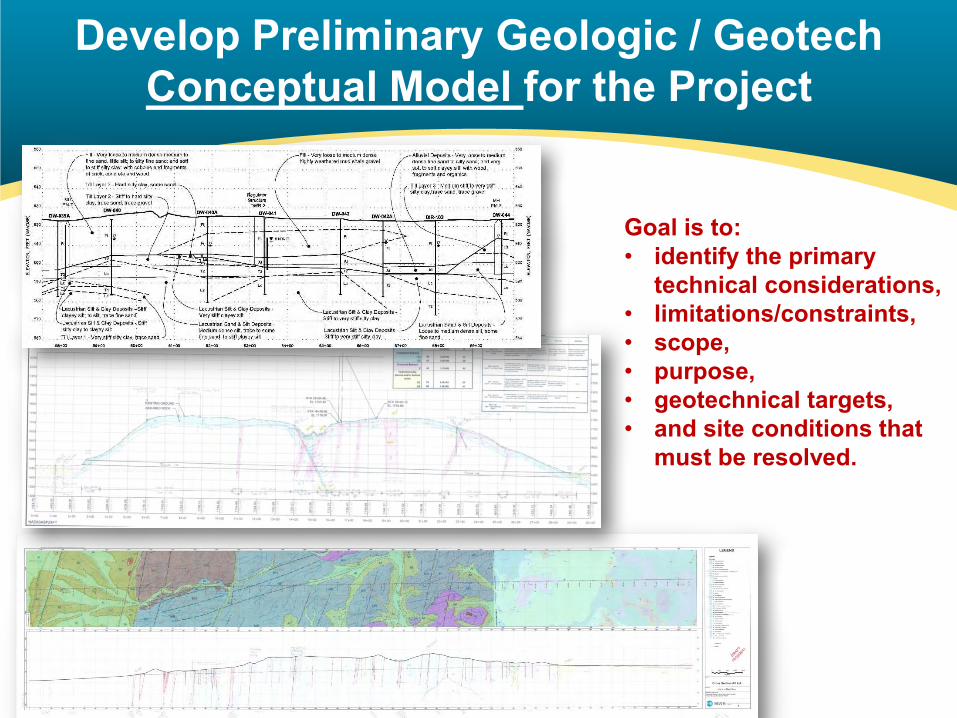
Develop Preliminary Geologic / Geotech Conceptual Model for the Project
Goal is to: • identify the primary
technical considerations, • limitations/constraints, • scope, • purpose, • geotechnical targets, • and site conditions that
must be resolved.
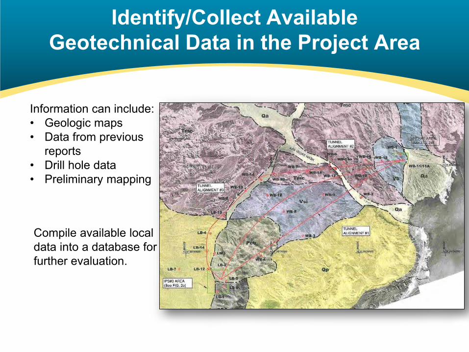
Identify/Collect AvailableGeotechnical Data in the Project Area
Residential Area
Bridge or control structure
Roads or Canals
Information can include:• Geologic maps• Data from previous
reports• Drill hole data• Preliminary mapping
Compile available local data into a database for further evaluation.

Field Geologic Mapping

Typical Drill Hole Logs
Soil:• Lithology• Soil type (USCS)• Color• Consistency /
density• Grain size
distribution• Moisture• Cementation• Plasticity (clays)• Roundness
Rocks:• Rock Type• Recovery, RQD,
GSI• Color• Texture• Degree of
weathering• Strength• Hardness• Structure• Discontinuities:
o Typeo Widtho Infilling Amount
& Typeo Surface Shapeo Roughnesso Spacing (Joint
Sets)
General:• Drill rate• Rig Behavior• Circulation return• Depth to water• Instrumentation• Drill difficulties• Shift changes• Testing intervals and
results
Roughness Code
SlickensidedPolished
Smooth
RoughVery Rough

Types of Samples –Drive Samplers (SPT, MC, LPT)
SPT Energy Calibration
MC Liners
Can be performed in most soil types, difficult in gravel-cobbles. Provides information relating to relative density, strength, and applicability of some ground improvement methods (e.g., soil mixing, jet grouting, chemical grouting)
Mod Cal

Types of Samples –“Undisturbed” Samples
Pitcher Sampler
Piston Sampler
Shelby Tube
Typically applied to soft-medium, stiff cohesive soils in order to test strength, stiffness, consolidation, etc…

Types of Rigs –
Solid Stem
Hollow Stem
• Auger• Mud/Air Rotary• Mud/Air Rotary with Casing Advance• Reverse Circulation• Sonic• Becker Penetration • Large Diameter• Cone Penetration Tests (CPT)• Rock Core
Some typical methods to drill the subsurface include:
Each of these methods have pros and cons and are well suited for specific exploration programs, depending on both the subsurface conditions as well as the data needs for the program.

Typical Drill Hole LogsRock Log Soil Log
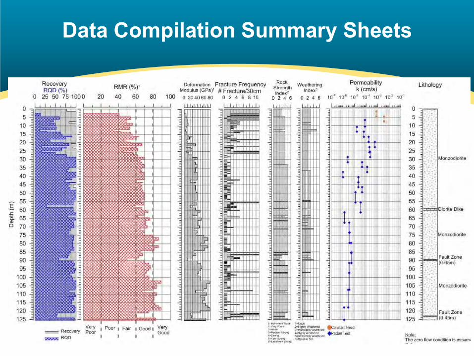
Data Compilation Summary Sheets

Cone Penetration Test (CPT)
Pros:• Widely available• Efficient• No water, mud or air• Advance many holes in comparison
Cons:• No samples• Push depth limitations

Borings Reduce Cost Uncertainty

Geophysics
• Down hole geophysics• Seismic reflection• Seismic refraction• Resistivity• Ground penetrating radar• Seismic tomography• Bathymetry• Magnetics

Reflection Profile

Marine Geophysics

Marine Seismic Refraction

Typical Lab Testing
• Soil– USCS classification– Strength & Modulus– Moisture/density– Plasticity– Gradation
• Rock– Rock classification– Compressive/shear strength – Tensile strength– Moisture/density– Durability, abrasivity, slake, toughness

Geologic Profiles –Understand Geologic Setting

• Settlement• Flowing Ground• Soft Soil Settlement• Faults and Joints • Heavy Ground• Squeezing Ground• Rock Burst• Mixed Face • Mixed Ground• Obstructions• Water bearing features
& Water Table• Groundwater Control• Natural Gas
Risk Topics
• Friction• Stickiness• Sensitive Soils• Impacts of fines on
slurry separation• Soil Conditioning• Abrasion• Invert Degradation

Settlement
0.05 SMAX
Average Slope = Smax / W
W2.5i
SMAX
Ground Surface
Z Settlement Influence Line
D = 2R
i
-Y2/(2 i 2)S = VS
i 2P
YVS Adjacent Structure

Settlement Mechanisms
• Tunneling operations have inherent risks of settlement from:– Excessive overcut– Excessive or uncontrolled spoil
removal– Driving of temporary soil
supports– Inflow of water in granular soils
Mechanisms for Tunnel Settlements

Settlement Monitoring
• Settlement should be controlled by:– Designing construction methods to
prevent settlement– Continued monitoring of surface and
subsurface conditions for settlement or indicators
– Extensometers:

Flowing Ground
wet sand
Sinkhole
Flowing, running ground
wet fine sand
clay
silt Flowing Ground in TBM

Flowing Ground - Tunnelman’s Ground Classification

Soft Soil and Ground Consolidation
• Normally Consolidated Clay: The present overburden pressure is the most the soil has ever seen.
• Overconsolidated Clay:The present overburden pressure is less than the soil has experienced in the past.

Soft Soil Settlement
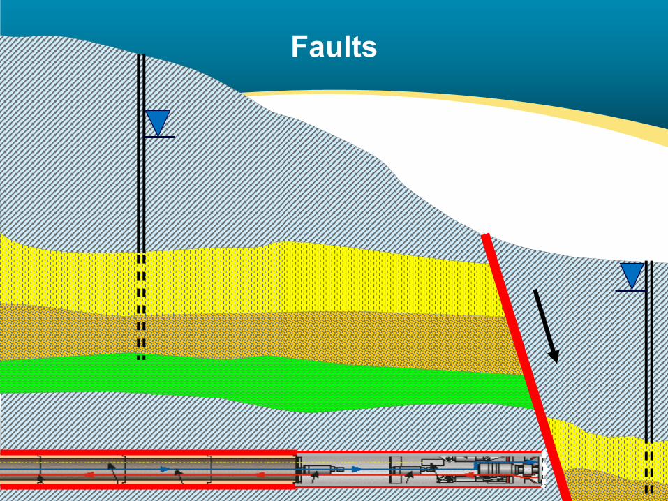
Faults

Fault Inflow in to Tunnel
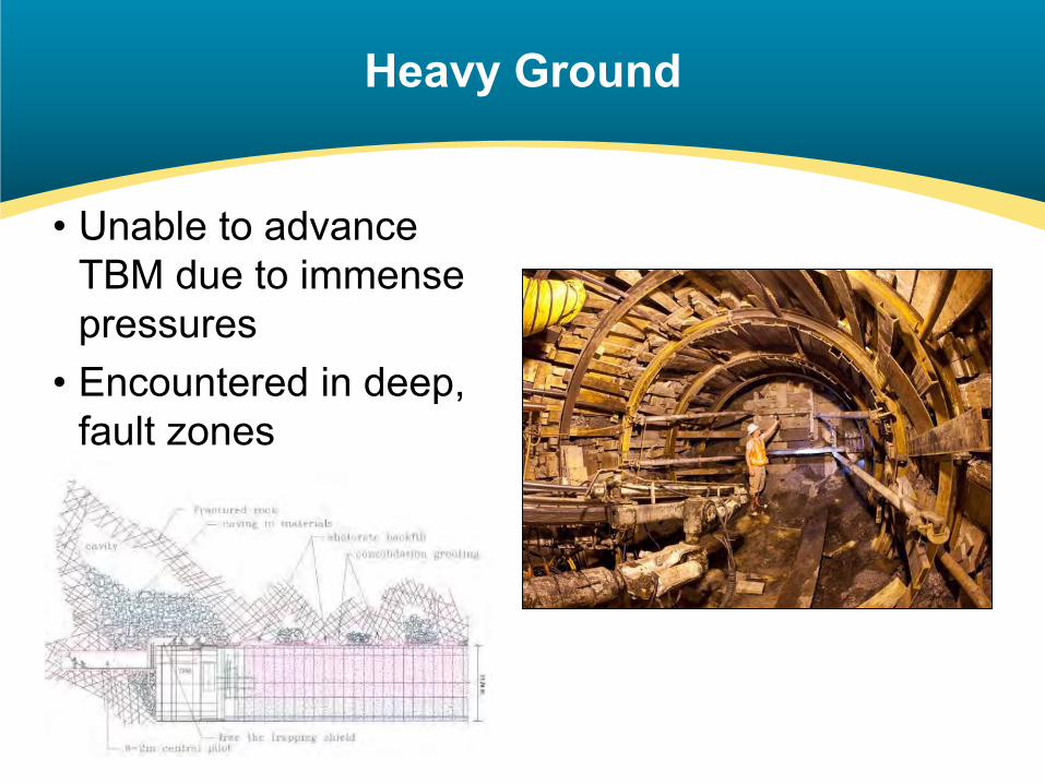
Heavy Ground
• Unable to advance TBM due to immense pressures
• Encountered in deep, fault zones

Terzaghi’s Rock Load Classification

Faults and Joints - Outcrop Mapping

Faults and Joints - Cross Hole Geophysics / Tomography

Squeezing Ground

Rock Burst Potential
- In-situ Stress- Brittleness- Stored Energy- Released
Energy

Typical Lab Testing
• Rock– Rock classification– Compressive/shear strength – Tensile strength (Brazilian)– Moisture/density– Durability, abrasivity, slake, toughness

Mixed Face / Line and Grade

Mixed Face - Seismic Refraction

Mixed Ground Conditions

Obstructions
Abandoned Ground Support Systems
Old Foundation Block
BouldersWells and Casings
Piles and Building Foundations

Obstructions - Geology, GPR, Well Records, Utilities
Geologic Environment / Prior Experience
Ground Penetrating Radar (GPR)
Well Records Pothole Utilities

Obstructions - Test Pits and Large Diameter Borings
Test Pits: Used for soil logging, sample collection and lab testing materials anticipated to be encountered.
Large Diameter Borings

Water Bearing Features & Water Table Location
TunnelAlignment
Shaft
Scre
en
Scre
enScre
en
FracturedRock
Highly permeable sand-gravel
Clay

Groundwater Characterization
• Characterization– Water wells– Packer testing

Multi-level Single
Locate Water - Piezometers
Typical stand-pipe piezometerMulti-level vibrating
wire piezometer
Fully Grouted Multi-level vibrating wire piezometer

Packer Testing
Inflation Tube
Perforated Screen
Inflatable Packer
Test Zone
End Cap
End Plug

Groundwater Control
• Grouting inside of tunnel

Hazardous Gases & Contaminants Underground
• Methane (CH4)• Hydrogen Sulfide (H2S)• Carbon Dioxide (CO2)• Gasoline Vapors / Hydrocarbons• Chlorinated Solvents (PCE, DCE, & TCE)

Gas - Sampling Methods

Friction
General Description Grain Shape Loose, φ (deg) Dense, φ (deg)
Ottawa Standard Sand Well Rounded 28 35Eroded Sandstone Rounded 31 37Fluvial Silty Sand Subrounded 33 37Glacial Silty Sand Subangular to
subrounded36 40
Great Salt Lake Sand Angular 38 47Well-graded, compacted crushed rock
Angular - 60
Holtz & Kovacs, 1981

Large Diameter Pipe Jacking Application
Earth Pressure BalanceSlurryCutter Boom Shield
BackacterShield
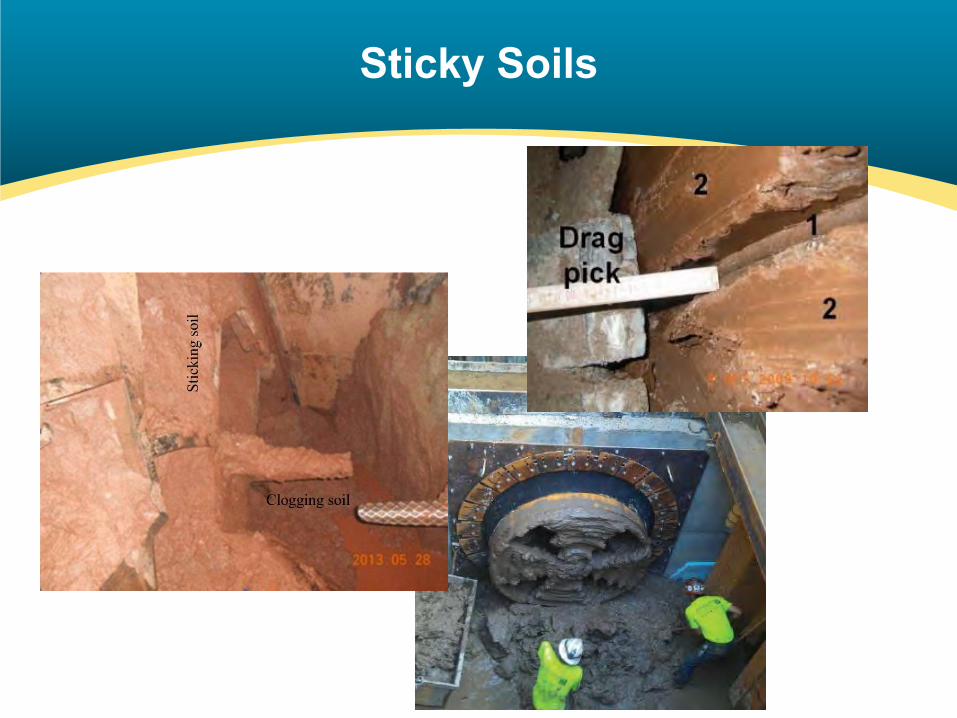
Sticky Soils

Stickiness – Clogging Potential(Thewes, 2005)
Low
Medium
High
EPBM Clogging Potential

Plasticity Testing

Sensitive Soils / Collapsible Soils

Abrasivity - High Wear from Abrasion

Abrasivity - Cerchar Tests & Thin Section Analysis
Granitic Porphyry Thin Section

Abrasivity - Soil Laboratory Testing
Millers Drilling Index (ASTM G75-01)
RAR - Relative Abrasion Resistance

Fines in Slurry - Slurry Separation Plant

Fines in Slurry
1” ½” #4 #10 #40 #200
Hydrometer Test
Grain Size Analysis

Invert Degradation

Interventions

Risk Can be Managed but Not Eliminated
“Surprises Are Inevitable - There will
always be unexpected ground conditions
and neither the owner nor the design
team can completely eliminate surprises
from complex underground projects.”
Gould, 1995