general description important data for the vru...
TRANSCRIPT

Document : SERV01/3000-Commercial/Standard Documents/NT-01-01-06 E Page 1 of 13
38 rue de Paris tel: +33 1 45 98 00 17 94470 Boissy Saint Leger fax: +33 1 43 82 68 84 France
Vapour Recovery Systems
General Description Important data for the VRU sizing
(see the questionnaire)
CarboVac Ref. No.: NT-01-01-06-E

Document : SERV01/3000-Commercial/Standard Documents/NT-01-01-06 E Page 2 of 13
Contents
1 Process description ............................................................................................................. 3
2 Process Control .................................................................................................................. 4
3 design Requirements .......................................................................................................... 5
3.1 Instantaneous Flow Rate Q(i) ......................................................................................... 5 3.2 Volume loaded per Cycle Q(c) ....................................................................................... 6 3.3 Volume loaded in a period of 4 hours Q(4) ................................................................... 7 3.4 Volume loaded per day Q(d). ......................................................................................... 7 3.5 Hydrocarbon concentration ............................................................................................ 7 3.6 Vapour holder effect ....................................................................................................... 7
4 Recovered Product ............................................................................................................. 8
5 Materials used .................................................................................................................... 9
5.1 Activated Carbon ............................................................................................................ 9 5.2 The Vacuum System .................................................................................................... 10 5.3 Sequential Valves ......................................................................................................... 11 5.4 Absorbent Circulation Pumps ...................................................................................... 11
6 Safety Systems ................................................................................................................. 11
Document : SERV01/3000-Commercial/Standard Documents/NT-01-01-06 E Page 3 of 13
1 PROCESS DESCRIPTION
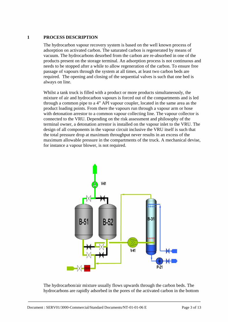
The hydrocarbon vapour recovery system is based on the well known process of adsorption on activated carbon. The saturated carbon is regenerated by means of vacuum. The hydrocarbons desorbed from the carbon are re-absorbed in one of the products present on the storage terminal. An adsorption process is not continuous and needs to be stopped after a while to allow regeneration of the carbon. To ensure free passage of vapours through the system at all times, at least two carbon beds are required. The opening and closing of the sequential valves is such that one bed is always on line. Whilst a tank truck is filled with a product or more products simultaneously, the mixture of air and hydrocarbon vapours is forced out of the compartments and is led through a common pipe to a 4” API vapour coupler, located in the same area as the product loading points. From there the vapours run through a vapour arm or hose with detonation arrestor to a common vapour collecting line. The vapour collector is connected to the VRU. Depending on the risk assessment and philosophy of the terminal owner, a detonation arrestor is installed on the vapour inlet to the VRU. The design of all components in the vapour circuit inclusive the VRU itself is such that the total pressure drop at maximum throughput never results in an excess of the maximum allowable pressure in the compartments of the truck. A mechanical devise, for instance a vapour blower, is not required.
The hydrocarbon/air mixture usually flows upwards through the carbon beds. The hydrocarbons are rapidly adsorbed in the pores of the activated carbon in the bottom
Document : SERV01/3000-Commercial/Standard Documents/NT-01-01-06 E Page 4 of 13
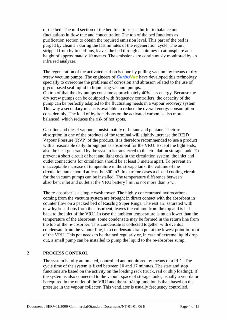
of the bed. The mid section of the bed functions as a buffer to balance out fluctuations in flow rate and concentration The top of the bed functions as purification section to obtain the required emission level. This part of the bed is purged by clean air during the last minutes of the regeneration cycle. The air, stripped from hydrocarbons, leaves the bed through a chimney to atmosphere at a height of approximately 10 meters. The emissions are continuously monitored by an infra red analyzer. The regeneration of the activated carbon is done by pulling vacuum by means of dry screw vacuum pumps. The engineers of CarboVac have developed this technology specially to overcome the problems of corrosion and abrasion related to the use of glycol based seal liquid in liquid ring vacuum pumps. On top of that the dry pumps consume approximately 40% less energy. Because the dry screw pumps can be equipped with frequency controllers, the capacity of the pump can be perfectly adapted to the fluctuating needs in a vapour recovery system. This way a secondary means is available to reduce the overall energy consumption considerably. The load of hydrocarbons on the activated carbon is also more balanced, which reduces the risk of hot spots. Gasoline and diesel vapours consist mainly of butane and pentane. Their re-absorption in one of the products of the terminal will slightly increase the REID Vapour Pressure (RVP) of the product. It is therefore recommended to use a product with a reasonable daily throughput as absorbent for the VRU. Except the light ends, also the heat generated by the system is transferred to the circulation storage tank. To prevent a short circuit of heat and light ends in the circulation system, the inlet and outlet connections for circulation should be at least 3 meters apart. To prevent an unacceptable increase of temperature in the storage tank, the volume of the circulation tank should at least be 300 m3. In extreme cases a closed cooling circuit for the vacuum pumps can be installed. The temperature difference between absorbent inlet and outlet at the VRU battery limit is not more than 5 ºC. The re-absorber is a simple wash tower. The highly concentrated hydrocarbons coming from the vacuum system are brought in direct contact with the absorbent in counter flow on a packed bed of Raschig Super Rings. The rest air, saturated with new hydrocarbons from the absorbent, leaves the column from the top and is led back to the inlet of the VRU. In case the ambient temperature is much lower than the temperature of the absorbent, some condensate may be formed in the return line from the top of the re-absorber. This condensate is collected together with eventual condensate from the vapour line, in a condensate drain pot at the lowest point in front of the VRU. This pot needs to be drained regularly or, in case of extreme liquid drop out, a small pump can be installed to pump the liquid to the re-absorber sump.
2 PROCESS CONTROL
The system is fully automated, controlled and monitored by means of a PLC. The cycle time of the system is fixed between 10 and 17 minutes. The start and stop functions are based on the activity on the loading rack (truck, rail or ship loading). If the system is also connected to the vapour space of storage tanks, usually a ventilator is required in the outlet of the VRU and the start/stop function is than based on the pressure in the vapour collector. This ventilator is usually frequency controlled.

Document : SERV01/3000-Commercial/Standard Documents/NT-01-01-06 E Page 5 of 13
Systems directly connected to a truck or rail loading rack are designed with an extra volume of activated carbon to balance the variations in flow rate and concentration. Since the unit is designed for a maximum daily vapour profile, it is not necessary to start the regeneration cycle every time a truck enters into the loading rack. The PLC counts the number of trucks and allows the system to start only if it is sure that at least one full regeneration cycle can be run. An activated carbon bed is considered to be sufficiently regenerated as soon as a preset vacuum level is reached. If this level is reached too soon, the vacuum pump speed will be reduced to a minimum to save energy and to prevent over-regeneration of the carbon. If the level is not yet reached after the preset time, the cycle may be prolonged, if the other bed is still not sufficiently saturated. If the other bed is sufficiently saturated, the system will switch at its preset cycle time and come back to the first bed afterwards, etc. If the desired vacuum level is reached and the other bed is still not sufficiently saturated, the system switches to “stand-by”. In “stand-by” position one bed is left on line, but all pumps are stopped. As soon as the preset number of trucks ( or part of) loaded on one bed is reached, the system re-starts. To prevent that the sump of the re-absorber column can be fully emptied and the return pump runs dry, a level control system is installed, controlling the speed of the return pump. All process control parameters are freely adjustable via the PC screen and by modem. More than 500 process parameters can be accessed and make it possible to optimize the system fully for the specific loading profile of the terminal at any time. See also the “flow diagram” of the process.
3 DESIGN REQUIREMENTS
The VRU is usually designed for a maximum daily loading profile, in order to assure compliance with the emission laws under all circumstances. The loading profile forms the basis for the selection of the most efficient combination of activated carbon volume and capacity of the vacuum system. This maximum profile usually occurs only sporadically. The capacity of a VRU based on activated carbon cannot easily be enhanced in a later stage, unless precautions have been taken in the design. The terminal owner should include his enlargement assumptions for the near future in the design basis of the VRU (for instance an additional loading bay). The daily loading profile is characterized by following periodical loading volumes. Each of these values determines a specific part of the VRU.
3.1 Instantaneous Flow Rate Q(i) The developed volume of vapour shall pass through the VRU under all loading circumstances, without opening of any over pressure safety device wherever in the system. This parameter is used to calculate the pressure drop of all components in line of the vapour flow (truck coupler, vapour arm/hose, flame arrestor on the loading spot, common vapour collecting line to the VRU and the VRU itself). According to the EU Directive, the truck coupler should be designed to accept a minimum pressure 55 mbarg at maximum loading speed. The VRU itself is usually designed for a pressure drop of 25 to 30 mbar. This means that 25 to 30 mbar is available for the pressure drop of the collecting system. The pressure drop of the

Document : SERV01/3000-Commercial/Standard Documents/NT-01-01-06 E Page 6 of 13
VRU is determined by the diameter/height ratio of the carbon beds, the diameter of the vapour lines and the inlet flame arrestor. The flow rate per loading spot is determined by the number of loading arms that can be in operation simultaneously and the capacity of the loading arms. For truck loading most commonly used are 4”API loading arms. For reasons of static electrical charge, the flow rate is limited to 144 m3/h for gasoline and 108 m3/h for diesel loading. A modern truck loading spot is usually equipped with 4 to 6 loading arms. The truck driver connects one or two arms and starts loading, than he connects one or two more. Not more than 4 arms are usually in operation at the same time. The larger the terminal the lower the average number of loading arms simultaneously in operation. A useful estimate is given by the following formulas:
Na = (Ns x 2) + 2 And
Q(i) = Na x Ca Na = number of arms connected simultaneously Ns = the number of spots Ca = average arm capacity in m3/h For two spots we usually take 8 loading arms connected and for very large terminals (Ns>10) the average number may be even less than 2 per spot. For the determination of Q(i) we take an average arm capacity of 135 m3/h. The flow rate may also be limited by the maximum simultaneous pumping rates of the loading pumps. Rail car filling stations can be either “on-spot” or “in-line”. The flow rates depend on the capacity of the loading lance, respectively the pumping flow rate.
3.2 Volume loaded per Cycle Q(c) The time required to load a truck or a rail car is 5 to 7 minutes. The time required to move in the next truck or rail car (on-spot) is also 5 to 7 minutes. The total truck or rail car “turn-around” time is usually taken at an average of 15 minutes (c=15). The usual net product volume of a truck is 35 m3 and that of a rail car 60 or 80 m3. Also larger or smaller capacities are possible. The total volume loaded in a 15 minute period is calculated as follows:
Q(c) = Ns x Vt Vt = net volume of the tanker Q(c) predominantly determines the volume of activated carbon per bed. The cycle time of a vapour recovery system is best chosen equal to the truck turn around time. Short cycling would reduce the volume of carbon per bed, but increases the risk of imbalance of hydrocarbon loads on the activated carbon with periodical emission peaks.

Document : SERV01/3000-Commercial/Standard Documents/NT-01-01-06 E Page 7 of 13
For purely continuous loading systems, like in-line loading of rail cars and ship loading, the cycle time of the VRU can be reduced to minimum 10 minutes. Q(c) would than be calculated as the loading rate Ql divided by 60/c (60/c = 4 to 5).
3.3 Volume loaded in a period of 4 hours Q(4) As a result of the distribution network, social and demographical circumstances, the activity on truck loading terminals show specific peaks. The largest peak occurs in the early morning and one or two lesser peaks in the afternoon and towards the evening. The largest peaks occur immediately after opening on terminals that are closed during the night. The 4 hour loading volumes are very specific for each terminal. Maximum 16 trucks could be loaded theoretically per spot in a 4 hour period, but practically only 10 to 12 trucks. For larger terminals the number drops to average 8 to 10 trucks per spot. On the average rail loading spot a complete train (1000 m3) can be loaded in 2,5 to 3 hours. The time lost between two trains is usually around 1 hour. Q(4) predominantly determines the required capacity of the vacuum system.
3.4 Volume loaded per day Q(d). This figure is specific for the terminal. It is important to know weather the terminal is open all day or only part of the day. Depending on the ratio between the volume loaded per cycle, in 4 hours and the daily volume, the capacity of the vacuum system can be reduced. Within limits the vacuum system can regenerate extra loads of hydrocarbons on the activated carbon during low activity periods on the loading rack.
3.5 Hydrocarbon concentration With the coming into effect of stage 1 of the European Directive 94/63 EC, the relatively saturated vapours of the ground tanks of the service stations is balanced back to the truck during truck unloading. The concentration of gasoline vapours is around 40% (1200 g/m3), whilst that of diesel vapours is almost 0 (1 g/m3). In most countries the trucks used for distribution are multi-compartment trucks for gasoline, diesel, jet-A1 and heating oils. The recovered vapours will therefore be a mixture of concentrations in the range of 20 to 25%. This vapour concentration constitutes for 80% the concentration of the vapours going to the VRU. Only 20% of the composition of the vapours is originates directly from the product loaded into the compartment. The recovery of vapours from the ground tanks of the service stations is therefore very cost effective and improves the overall return of investment drastically. The concentration predominantly influences the required capacity of the vacuum system and has almost no influence on the required volume of activated carbon.
3.6 Vapour holder effect The CarboVac VRU does not need a gasholder to balance out the variations in flow rate and concentration. In fact the activated carbon itself is a far more effective buffer for hydrocarbons than a mechanical vapour holder.

Document : SERV01/3000-Commercial/Standard Documents/NT-01-01-06 E Page 8 of 13
In a gasholder a gaseous mixture of hydrocarbons and air is stored. Activated carbon stores only the hydrocarbons and on top of that, in liquid form. This makes 1m3 of activated carbon equivalent to around 250m3 of gasholder capacity. The mid section of the carbon bed is used as buffer zone for hydrocarbons. The regeneration method used by CarboVac, based on a stable vacuum end pressure, ensures the availability of this buffer at all times. VRU start/stop control systems based on emission monitoring value push the saturated zone of the activated carbon high up in the bed and sometimes even past the buffer zone into the purification zone. The result is that the buffer zone may not be available at the time it is needed and on top of that elevated adsorption temperatures may occur in the top of the bed, with risk of a carbon bed heat-up. The starting method has an almost negligible influence on the energy consumption of the system and is therefore not recommended.
4 RECOVERED PRODUCT
The number of components present in gasoline and diesel vapours is numerous. The major part, however, consists of butane and pentane. The average molar mass of the pure vapour is around 65 g/mole. The average concentration of pure gasoline vapours is 40% by volume. The mass of recovered product can be calculated as follows. 1 Nm3 of inlet vapour contains 400 litres of hydrocarbons. This is 400/22,5 x 65 grams of HC, or 1161 g HC/m3. In the outlet of the VRU we find less than 5 g/m3. The recovered mass of hydrocarbons is therefore more than 1158 g/m3. The liquefied butane/pentane mixture has a density of approximately 600 kg/m3. The volume of product recovered per m3 gasoline vapour treated is at least 1,9 litres. This volume goes back to the storage tank. Increasingly the taxes on gasoline sales are based on volume entering into the terminal. The calculation below is hypothetical but illustrative for the potential benefits of the installation of a gasoline vapour recovery system. Basic assumptions: Sales price of 1 litre gasoline at the service station = 1 € per litre Tax at the inlet of the terminal = 0,60 € per litre Cost price of the product = 0,20 € per litre Product sold = 1000 litres Product recovered = 1,5 litres per m3 vapour treated. before VRU after VRU Product sold in litres 1000,00 1000,00 Product bought in litres 1000,00 998,50 Product sold in € 1000,00 1000,00 Tax paid in € 600,00 599,10 Cost of the product bought in € 200,00 199,70 Gross margin in € 200,00 201,20

Document : SERV01/3000-Commercial/Standard Documents/NT-01-01-06 E Page 9 of 13
The increase in gross margin is in the order of 1,20 € par m3 product sold at the service station. In some European countries a tax exemption of 1,15 litres per 1000 litres leaving the terminal is granted The calculation is than as follows: before VRU after VRU Product sold in litres 1000,00 1000,00 Product bought in litres 1000,00 998,50 Tax basis 1000,00 998,85 Product sold in € 1000,00 1000,00 Tax paid in € 600,00 599,31 Cost of the product bought in € 200,00 199,70 Gross margin in € 200,00 200,99 The increase in gross margin is in the order of 1 € par m3 product sold at the service station.
5 MATERIALS USED
Quality and reliability are the prevailing factors for the choice of materials and equipment used in a CarboVac VRU and insures the satisfaction of end user with his equipment on the long term. On top of that, equipment, spare parts and services must be quickly and universally available. CarboVac wants to be an anticipating and reactive VRU supplier and not a reactionary one. To support these goals we form partnerships with our principal sub-suppliers.
5.1 Activated Carbon Activated carbon can be manufactured from wood, bitumen or charcoal. Wood based carbon has the lowest density and the most open pore structure. The important specifications for the selection of activated carbon for VRU applications are: resistance against aging, sensitivity for the development of hot spots and the pressure drop. The pore structure of wood based carbon is most suitable for application in vapour recovery systems. The mini, meso and macro pores are evenly distributed. The activation was done by phosphoric acid, which makes it necessary to rinse the carbon thoroughly with water afterwards to obtain a pH-neutral product. Because of it high reactivity, the carbon is also more sensitive for the formation of hot spots during the first period of operation. Coal based carbons have a much larger percentage of mini pores at the expense of the meso pores. This makes this type of carbon more sensitive for aging. Aging is caused by the formation of an oily heel, built up from high boiling hydrocarbons (e.g. isobutanol) from the gasoline vapour. Due to the narrow pore structure the heel is slowly restrained from participation in the cyclic adsorption/regeneration process. The carbon looses a considerable part of it adsorption capacity in 5 to 10 year of operation. The sensitivity for hot spots is less than that of wood based carbon.

Document : SERV01/3000-Commercial/Standard Documents/NT-01-01-06 E Page 10 of 13
The extreme internal active surface of the carbon (1200 to 1800 m2/gram) offers much opportunity for the hydrocarbons to come in contact with oxygen from the air and start an oxidation reaction at relatively low temperature. Once such a reaction has started, it will develop some heat and this heat will accelerate the reaction. At temperatures above 100°C the reaction becomes automatic. This means that the temperature increases constantly as long as oxygen is present. In the course of one or more days a real carbon bed heat-up can develop with temperatures up to 200°C. A carbon bed fire has not been experience until today in vacuum regenerated vapour recovery systems. The raison for this may be found in the fact that the cycle time is relatively short and the oxidation reaction is interrupted by pulling vacuum (lack of oxygen). The hot spot will be fully desorbed during the vacuum phase so that also no fuel is present anymore. During the new adsorption cycle new hydrocarbons will arrive in the virgin and still hot spot and the temperature will rise again. The carbon beds are equipped with temperature sensors, which will shut the system down and close all valves. The oxidation reaction is deemed to stop due to lack of oxygen. Two types of activated carbon are used in the CarboVac VRU. The CECA ACX carbon is wood based, but the reactivity is tempered by using a binder of a special raisin, which is not carbonized in the production process. The binder gives a slight hygroscopic property to the carbon, which reduces the heat of adsorption by substitution. The Carbochem carbon type VS50 is a coal based carbon in which part of the mini pores are super activated to for meso pores. The expected life time of both carbons is estimated at more than 15 years in combination with the dry vacuum system and control of the desorption-end-pressure as described before.
5.2 The Vacuum System The required vacuum level for the vacuum regeneration process lies between 25 and 100 mbar absolute. The lower vacuum levels are required for pure high boiling products like benzene and alcohols. The pump capacities required for this kind of systems is relatively large. Important features of the vacuum pump system are explosion proof design, no metallic contact of internal parts, relatively low process temperature, capability to transfer slugs of liquid (part of the desorbed products at high concentration condensate inside the pump at near ambient temperatures), low power consumption, low maintenance requirements, high reliability and a life expectancy of at least 15 years. The first generation of vapour recovery systems used liquid ring vacuum pumps, using a glycol-water mixture as seal liquid. The continuous and turbulent contact of the glycol with air causes oxidation of the glycol and formation of acids. Although this process can be slowed down by introducing anti- oxidation dopes, it is usually necessary to change the fluid once per year. The formation of acids causes excessive corrosion and abrasion inside the system and the pumps with loss of capacity and increase of power consumption. An other type of pump applied in vapour recovery systems is the oil lubricated rotary vane pump. This pump is however not explosion proof and cannot handle liquid slugs without damaging the oil film that lubricates the metal to metal contact between vanes and the inside of the pump housing. The loss of oil to the re-absorber

Document : SERV01/3000-Commercial/Standard Documents/NT-01-01-06 E Page 11 of 13
is not a problem for gasoline applications, but cannot be accepted for applications in pure products, like benzene. The maintenance requirements are elevated. CarboVac uses dry screw vacuum pumps type Cobra, manufactured by BUSCH Company in Switzerland. This pump complies with all requirement mentioned above, whilst CarboVac and Busch engineers in close co-operation have enhanced the pump to adapt perfectly to the VRU application. A secondary advantage is that the pumps can be fully speed controlled to adapt the capacity to the variable requirements. The pumps are completely manufactured from nodular cast iron type GGG40. The inner parts are PTFE coated. The bearing on both end are oil lubricated. Intermediate chambers between pump section and the bearings prevent any contact of the lubricant with the process fluids. BUSCH Company is a worldwide recognized vacuum pump supplier with entities in almost all countries of the world. BUSCH and CarboVac entered into an after sales service settlement in which the preventive maintenance and emergency call outs are agreed. The overall responsibility for an eventual maintenance agreement between CarboVac and the end user remains with CarboVac Company. The local Busch service engineers are fully trained to provide the end user with any operational assistance.
5.3 Sequential Valves Most of the historical system failures are related to malfunctioning of the electrically operated sequential valves and limit switches. CarboVac therefore strongly recommends the use of pneumatically operated valves. In case no air is available on the terminal a small standard off the shelf ATLAS COPCO twin piston compressor with air buffer is supplied with the unit. The sequential valves used in the VRU are of the double eccentric butterfly type with stainless steel disk. The seal rings are PTFE. Approved valve suppliers are Neles, Sodeco and Flowseal.
5.4 Absorbent Circulation Pumps The absorbent circulation pumps are of the centrifugal type according ISO2858 with single mechanical seal. If the clients budget allows we prefer to use KSB type canned motor pumps. These pumps have an outstanding record of application in vapour recovery systems. By using this hermetically closed pump, also the last possible source of leakage of absorbent inside the VRU battery limit is eliminated. This type of pump is also a good alternative for cases where API 610 type pumps are specified by the customer. API pumps are hardly available on the market for the small capacity range required for standard VRU’s.
6 SAFETY SYSTEMS
CarboVac supplies an ATEX Explosion Protection Document with the VRU, as per the European Directive 94/9EU. The VRU is considered to be a unit as per §3.7.1 of the directive. The basic safety feature of the unit is its entire explosion proof design. The unit resists the pressure of an eventual internal explosion. The direct

Document : SERV01/3000-Commercial/Standard Documents/NT-01-01-06 E Page 12 of 13
surroundings of the VRU, limited by the edge of its foundation can therefore be considered zone 2 according the CENELEC Rules. The vapour inlet line and the carbon beds can contain a vapour in the explosive range. A potential hot spot in a carbon bed can be seen as a source of ignition. Independent secondary measures are taken to limit the occurrence of the ignition source by installing temperature sensors at strategic points in the carbon beds. If the temperature in the beds exceeds 60°C the unit shuts down and the valves around the carbon beds are closed. The atmosphere inside the re-absorber column and the vacuum system is normally always above the higher explosion limit (HEL). A secondary measure here is formed by monitored injection of absorbent (in the top of the column and directly in to the screw compartment of the vacuum pump. Other tertiary safety measures taken are: - Monitoring of the discharge temperature of the vacuum pumps. - Monitoring of the operational parameters of each vacuum pump (VSC). - Monitoring of the sequential valve positions. - Independent high and low level switches on the re-absorber column. - Double fail closing valves on each absorbent line. - Level switch on the condensate drain point at the inlet of the VRU. Temperature sensors and level switches are included in a hard wired safety loop.
Vapour Recovery System installed on the Shell Truck Terminal of Arnhem, Holland. Capacity 1000 m3/h with an emission limit of < 10 g/m3.

Document : SERV01/3000-Commercial/Standard Documents/NT-01-01-06 E Page 13 of 13
Typical implementation diagram for a Marine application
Tanker
VRU
Naphta circulation (Absorbents liquid)
(Naphtha or gasoline) Tanker loading operation
Vapour from tanker
Naphta tank
Vapour from other
sources
Ventilator

Client:
E‐mail:
Ph:
Terminal name:
General Information : Ambient Temperature
Available Inlet Press. at VRU mbarg Summer max ° C
Height above Sea Level m Winter max ° C
Hght St. Tks above VRU m Winter min ° C
Distance St. Tks to VRU mDistance VRU to Loading Rack m Design Temperature
y/n ° C
temperature
V Hz
Electrical Data
Please provide us with a Plot plan (with scale) and when possible with the following information: location of electrical room / operator room / pump station / PLC room / Circulation tank / location available for VRU / pipe tracks…
When fullfil of the questionnaire please precise when necessary the terminal future expansion or rewamping so that we can
already calculate the design/cost impact of those changes on the VRU
Cooling water

TRUCK Truck average capacity m3
Truck average loading
time minute
Do they recover vapour
from Service stationYes / No
Do they can loaded diesel
after gasoline or they are
dedicated to one product
Explain
Pressure available at
vapour arm (if known) mbar
PRODUCT Product loaded:
Vapour pressure or
True vapor
pressure (mbar)
Temperature (°C) Ratio loaded (%)Quantity loaded per day
(m3)
Quantity loaded per year
(m3)
SOMME = 100%
TOP LOADING BAYS
PLEASE DESCRIBE THE TERMINAL AS IT WILL BE IN THE FUTURE (for instance some Top loading bays may be transform into Bottom)

LOADING
BAYSTop Loading bays Mono or bi side ?
N° of top loading arms
Products to be loaded Flow m3/hMax. nber of arms
connercted simultaneouslyMax instantaneous flow
generated by the bay
Max number of trucks to be loaded in 4 hours per
loading bays
Max trucks in loading operation at the same time
in the loading bays
Max instantaneous flow generated
by the whole loading installation
1 Arm 2 Arms3 Arms4 Arms5 Arms 6 Arms1 Arm 2 Arms3 Arms4 Arms5 Arms 6 Arms1 Arm 2 Arms3 Arms4 Arms5 Arms 6 Arms1 Arm 2 Arms3 Arms4 Arms5 Arms 6 Arms1 Arm 2 Arms3 Arms4 Arms5 Arms 6 Arms1 Arm 2 Arms3 Arms4 Arms5 Arms 6 Arms1 Arm 2 Arms3 Arms4 Arms5 Arms 6 Arms
n°7
n°5
n°6
n°3
n°4
n°1
n°2

TRUCK Truck average capacity m3
Truck average loading
time minute
Do they recover vapour
from Service stationYes / No
Do they can loaded diesel
after gasoline or they are
dedicated to one product
Explain
Pressure available at
vapour arm (if known) mbar
PRODUCT Product loaded:
Vapour pressure or
True vapor
pressure (mbar)
Temperature (°C) Ratio loaded (%)Quantity loaded per day
(m3)
Quantity loaded per year
(m3)
SOMME = 100%
BOTTOM LOADING BAYS

LOADING
BAYSbottom Loading bays Mono or bi side ?
N° of bottom loading arms
Products to be loaded Flow m3/hMax. nber of arms
connercted simultaneouslyMax instantaneous flow
generated by the bay
Max number of trucks to be loaded in 4 hours per
loading bays
Max trucks in loading operation at the same time
in the loading bays
Max instantaneous flow generated
by the whole loading installation
1 Arm 2 Arms3 Arms4 Arms5 Arms 6 Arms1 Arm 2 Arms3 Arms4 Arms5 Arms 6 Arms1 Arm 2 Arms3 Arms4 Arms5 Arms 6 Arms1 Arm 2 Arms3 Arms4 Arms5 Arms 6 Arms1 Arm 2 Arms3 Arms4 Arms5 Arms 6 Arms1 Arm 2 Arms3 Arms4 Arms5 Arms 6 Arms1 Arm 2 Arms3 Arms4 Arms5 Arms 6 Arms
n°1
n°2
n°3
n°4
n°6
n°7
n°5

VESSEL Vessel average capacity
vessel average loading
time hour
Are they inerted ? Which
gas ?
Do they can loaded diesel
after gasoline or they are
dedicated to one product
Explain
Pressure available at
vapour connection (if
known)mbar
PRODUCT Product loaded:
Vapour pressure or
True vapor
pressure (mbar)
Temperature (°C) Ratio loaded (%)Quantity loaded per day
(m3)
Quantity loaded per year
(m3)
SOMME = 100%
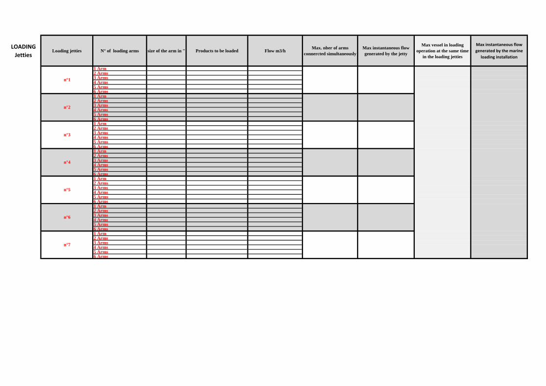
MARINE LOADING JETTIES
In the case of marine loading it is important to proceed a study to know distance from jetties to tank farm and to VRU. A plot plan will be helpful…
LOADING
JettiesLoading jetties N° of loading arms size of the arm in " Products to be loaded Flow m3/h
Max. nber of arms connercted simultaneously
Max instantaneous flow generated by the jetty
Max vessel in loading operation at the same time
in the loading jetties
Max instantaneous flow
generated by the marine
loading installation
1 Arm 2 Arms3 Arms4 Arms5 Arms 6 Arms1 Arm 2 Arms3 Arms4 Arms5 Arms 6 Arms1 Arm 2 Arms3 Arms4 Arms5 Arms 6 Arms1 Arm 2 Arms3 Arms4 Arms5 Arms 6 Arms1 Arm 2 Arms3 Arms4 Arms5 Arms 6 Arms1 Arm 2 Arms3 Arms4 Arms5 Arms 6 Arms1 Arm 2 Arms3 Arms4 Arms5 Arms 6 Arms
n°4
n°5
n°6
n°1
n°7
n°2
n°3
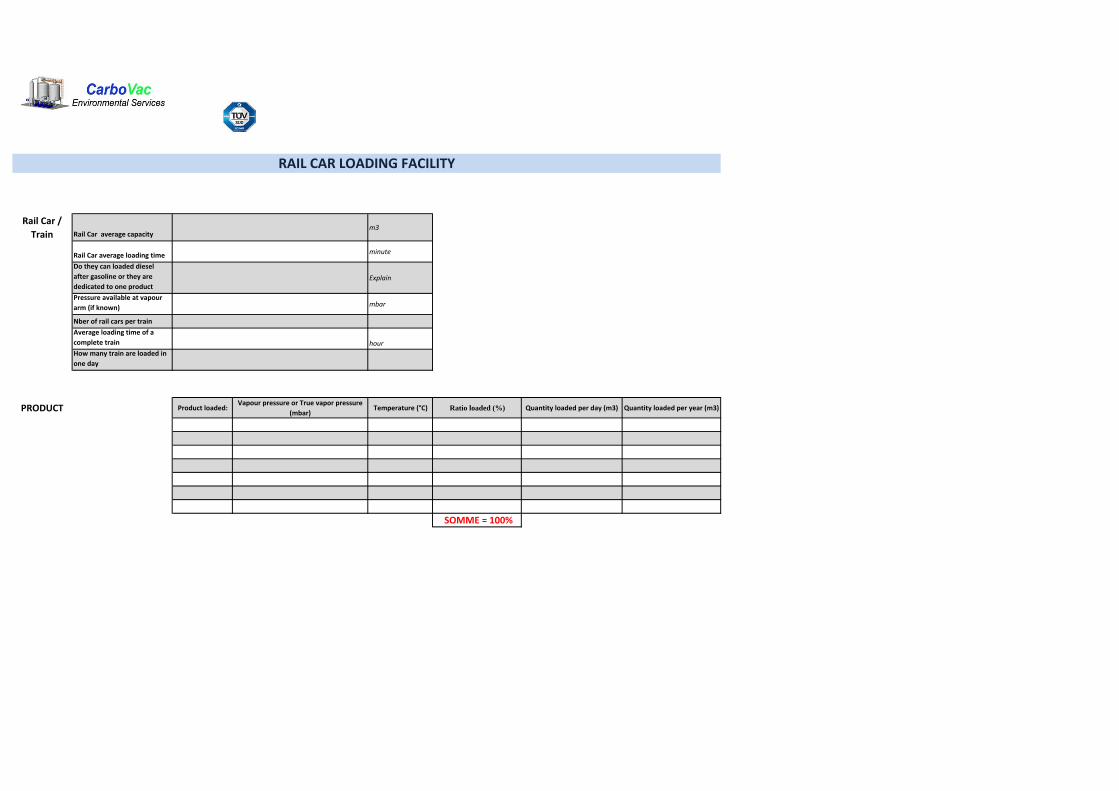
Rail Car /
Train Rail Car average capacitym3
Rail Car average loading time minute
Do they can loaded diesel
after gasoline or they are
dedicated to one productExplain
Pressure available at vapour
arm (if known) mbar
Nber of rail cars per train
Average loading time of a
complete train hour
How many train are loaded in
one day
PRODUCT Product loaded:Vapour pressure or True vapor pressure
(mbar)Temperature (°C) Ratio loaded (%) Quantity loaded per day (m3) Quantity loaded per year (m3)
SOMME = 100%
RAIL CAR LOADING FACILITY

LOADING
TRACKSLoading Track
Loading is: On Spot or In line
N° of loading point Arms per point Products to be loadedFlow m3/h per product if
different
Max. nber of arms connercted simultaneously
per rail car
Max instantaneous flow generated by rail car
Max number of rail car to be loaded in 4 hours in this
track
Max rail car in loading operation at the same time
in all the tracks
Max
instantaneous
flow generated by
the whole loading
installation
n°1
n°4
n°2
n°3
n°7
n°6
n°5

PRODUCT Product stored:
Vapour pressure or
True vapor
pressure (mbar)
Temperature (°C) Ratio loaded (%)Quantity loaded per day
(m3)
Quantity loaded per year
(m3)
SOMME = 100%
Filling Flow m3/h Unfilling Flow m3/h
TANKS by pipe/rail/truck/vessel… by pipe/rail/truck/vessel…
TANK FARM
TANKSFixed roof or Floating
roof tanks?Size (meter) Volume (m3) Products stored
Which tanks can be filled simultaneously
Max instantaneous filling flow generated by tank
farms (m3/h)
n°1
n°4
n°2
n°3
n°5
n°6
n°7
Pumping max capacity (m3/h)
Transfer tank to tank are possible ? (please precise
if necessary 1 to tank2,3,4…)
Flow Rate of those transfer
TO BE FILLED IF CLIENT WANTS TO CONNECT THE VRU TO ITS STORAGE TANKS, IF THE CLIENT DOESN'T WANT PLEASE FILL ONLY THE INFORMATION CONCERNING THE
ABSORBENT TANK
How long can be the filling at max flow rate ? (hour)