for combustion air
TRANSCRIPT

Variable Speed
Operation, Maintenance, and Parts
750-19810/2011
Drivefor Combustion Air

ii
TO: Owners, Operators and/or Maintenance Personnel
This operating manual presents information that will help to properly operate and care for the equipment. Study its con-tents carefully. The unit will provide good service and continued operation if proper operating and maintenance instruc-tions are followed. No attempt should be made to operate the unit until the principles of operation and all of thecomponents are thoroughly understood. Failure to follow all applicable instructions and warnings may result in severepersonal injury or death.
It is the responsibility of the owner to train and advise not only his or her personnel, but the contractors' personnel whoare servicing, repairing or operating the equipment, in all safety aspects.
Cleaver-Brooks equipment is designed and engineered to give long life and excellent service on the job. The electricaland mechanical devices supplied as part of the unit were chosen because of their known ability to perform; however,proper operating techniques and maintenance procedures must be followed at all times. Although these components af-ford a high degree of protection and safety, operation of equipment is not to be considered free from all dangers andhazards inherent in handling and firing of fuel.
Any "automatic" features included in the design do not relieve the attendant of any responsibility. Such features merelyfree him of certain repetitive chores and give him more time to devote to the proper upkeep of equipment.
It is solely the operator’s responsibility to properly operate and maintain the equipment. No amount of written instructionscan replace intelligent thinking and reasoning and this manual is not intended to relieve the operating personnel of theresponsibility for proper operation. On the other hand, a thorough understanding of this manual is required before at-tempting to operate, maintain, service, or repair this equipment.
Because of state, local, or other applicable codes, there are a variety of electric controls and safety devices which varyconsiderably from one boiler to another. This manual contains information designed to show how a basic burner operates.
Operating controls will normally function for long periods of time and we have found that some operators become lax intheir daily or monthly testing, assuming that normal operation will continue indefinitely. Malfunctions of controls leadto uneconomical operation and damage and, in most cases, these conditions can be traced directly to carelessness anddeficiencies in testing and maintenance.
It is recommended that a boiler room log or record be maintained. Recording of daily, weekly, monthly and yearly main-tenance activities and recording of any unusual operation will serve as a valuable guide to any necessary investigation.Most instances of major boiler damage are the result of operation with low water. We cannot emphasize too strongly theneed for the operator to periodically check his low water controls and to follow good maintenance and testing practices.Cross-connecting piping to low water devices must be internally inspected periodically to guard against any stoppageswhich could obstruct the free flow of water to the low water devices. Float bowls of these controls must be inspectedfrequently to check for the presence of foreign substances that would impede float ball movement.
The waterside condition of the pressure vessel is of extreme importance. Waterside surfaces should be inspected fre-quently to check for the presence of any mud, sludge, scale or corrosion.
It is essential to obtain the services of a qualified water treating company or a water consultant to recommend the properboiler water treating practices.
The operation of this equipment by the owner and his or her operating personnel must comply with all requirements orregulations of his insurance company and/or other authority having jurisdiction. In the event of any conflict or inconsis-tency between such requirements and the warnings or instructions contained herein, please contact Cleaver-Brooks be-fore proceeding.
DO NOT OPERATE, SERVICE, OR REPAIR THIS EQUIPMENT UNLESS YOU FULLY UNDERSTAND ALL APPLICABLE SECTIONS OF THIS MANUAL.
DO NOT ALLOW OTHERS TO OPERATE, SERVICE, OR REPAIR THIS EQUIPMENT UNLESS THEY FUL-LY UNDERSTAND ALL APPLICABLE SECTIONS OF THIS MANUAL.
FAILURE TO FOLLOW ALL APPLICABLE WARNINGS AND INSTRUCTIONS MAY RESULT IN SEVEREPERSONAL INJURY OR DEATH.
! DANGERWARNING

iii
Please direct purchase orders for replacement manuals to your local Cleaver-Brooks authorized representative
Manual Part No. 750-198
10/2011 Printed in U.S.A.
Cleaver-Brooks 2011
CLEAVER-BROOKSVariable Speed Drive
for Combustion AirOperation, Service, and Parts Manual

Notes

TABLE OF CONTENTS
Chapter 1Introduction
Introduction . . . . . . . . . . . . . . . . . . . . . . . . . . . . . . . . . 1-2Features . . . . . . . . . . . . . . . . . . . . . . . . . . . . . . . . . . . 1-3Specifications . . . . . . . . . . . . . . . . . . . . . . . . . . . . . . . 1-4
Chapter 2Installation
Mounting the Drive . . . . . . . . . . . . . . . . . . . . . . . . . . . . 2-2Wiring the Components . . . . . . . . . . . . . . . . . . . . . . . . . 2-4
Power Wiring . . . . . . . . . . . . . . . . . . . . . . . . . . . . . . 2-4Common Control Wiring . . . . . . . . . . . . . . . . . . . . . . . 2-6VSD Wiring. . . . . . . . . . . . . . . . . . . . . . . . . . . . . . . . 2-7
Configuring the Drive . . . . . . . . . . . . . . . . . . . . . . . . . 2-11PF400 DIP Switch Settings . . . . . . . . . . . . . . . . . . . 2-11DeviceNet Communications . . . . . . . . . . . . . . . . . . . 2-11Modbus Communications . . . . . . . . . . . . . . . . . . . . 2-13
Chapter 3Commissioning
Initial Startup . . . . . . . . . . . . . . . . . . . . . . . . . . . . . . . 3-2Drive Parameter Settings . . . . . . . . . . . . . . . . . . . . . . . . 3-2
PF70 and PF700 Parameters . . . . . . . . . . . . . . . . . . 3-3PF400 Drive Parameters . . . . . . . . . . . . . . . . . . . . . . 3-6
Combustion (Low) & High Air Pressure Switch Settings . . 3-7Display . . . . . . . . . . . . . . . . . . . . . . . . . . . . . . . . . . . . 3-7Drive "Autotune" . . . . . . . . . . . . . . . . . . . . . . . . . . . . . . 3-9Verifying Drive Operation . . . . . . . . . . . . . . . . . . . . . . . . 3-9
Chapter 4Normal Operation
Operation . . . . . . . . . . . . . . . . . . . . . . . . . . . . . . . . . . 4-2
Chapter 5Parts List / Drive Set Points
PF70 Drive and Recommended Line Reactor . . . . . . . . . 5-2PF700 Drive and Recommended Line Reactor . . . . . . . . 5-2PF400 Drive and Recommended Line Reactor . . . . . . . . 5-3Drive Set Points and CAPS & HAPS Ranges CB Boilers . . . 5-4Drive Set Points and CAPS & HAPS Ranges CBLE Boilers . 5-4Drive Set Points and CAPS & HAPS Ranges CBW Boilers . 5-5Drive Set Points and CAPS & HAPS Range 4WI Boilers . . 5-5
v

vi

www.cleaverbrooks.com
Chapter 1Introduction
Introduction . . . . . . . . . . . . . . . . . . . . . . . . . . . . . . . . . 1-2Features . . . . . . . . . . . . . . . . . . . . . . . . . . . . . . . . . . . . 1-3Specifications . . . . . . . . . . . . . . . . . . . . . . . . . . . . . . . . 1-4

Chapter 1 — Introduction
1.1 - IntroductionThe Cleaver-Brooks Variable Speed Drive (VSD) utilizes the Hawkcontrol system to supply a signal (Modbus or 4-20mA) to the VSD.The VSD will adjust the motor speed accordingly as the firing rate ofthe boiler changes.
This feature allows the blower motor to run at reduced speeds atlower firing rates, thereby providing electrical energy savings. Forthis variable torque application, the torque required varies with thesquare of the speed, and the horsepower required varies with thecube of the speed, resulting in a significant reduction of horsepowerfor a relatively small reduction in speed. The motor will consumeapproximately 42% as much energy at 75% speed than it will at100% speed.
The VSD also provides a "soft start" for the motor resulting in addi-tional electrical energy savings. Single-speed methods start motorsabruptly, subjecting the motor to a high starting torque and to cur-rent surges that are up to 10 times the full-load current. TheCleaver-Brooks VSD, on the other hand, gradually ramps the motorup to operating speed to lessen mechanical and electrical stress,reducing maintenance and repair costs, and extending the life of themotor and the driven equipment.
An additional advantage is lower fan and motor sound levels atreduced firing rates.
The VSD incorporates a graphical Human Interface Module (HIM)which displays drive parameters, fault annunciation and alarm con-ditions, as well as providing access to drive configuration and controlfunctions.
The Cleaver-Brooks drive is based on Allen-Bradley's PowerFlex driveseries. Depending on the motor size and supply voltage the drive willbe a PowerFlex 70 (PF70), PowerFlex 700 (PF700) or PowerFlex400 (PF400). The drive needs to be programmed with specificparameters depending on the application. Included in this manualare those parameters that need to be changed from the factorydefault settings. These parameters are specific to our design boilers/burners and should not be used for other applications.
The drive may be provided with a DeviceNet or Modbus adapterenabling communication to the Cleaver-Brooks Hawk boiler control-ler. Using either the DeviceNet or Modbus protocol, drive data, faultmessages, and fault clearing can be transmitted between the VSDand the Hawk controller.
Figure 1-1. VSD Mounted
Figure 1-2. Motor
1-2 Part No. 750-198

Chapter 1 — Introduction
P
This manual is provided as an application specific manual. Pleaserefer to the manual and supplements supplied with the VSD foradditional drive information.
1.2 - FeaturesStandard VSD Features:
• Factory configured parameters for optimum performance and Hawk ICS communications
• 7 Line Graphical Human Interface Module (HIM) (PF70 & 700)
• 2 Line 16 Character LCD Display (HIM built-in) (PF400)
• Alarm/Fault Indication
• On Screen (HIM) Fault Diagnostics
• Clearly marked wiring compartment
• Multi-Color LED's provide clear indication of drive status
• Integral I/O
• Flying Start - Provides smooth connection into rotating loads (boiler re-start)
• NEMA 1 Type Enclosure
Auxiliary Components: • Interposing Relays (for VSD enable and interlock)
Optional Features: • Connection to Cleaver-Brooks Hawk controls
• External Push Button for drive reset
• NEMA 4 or 12 installations
• Modbus/DeviceNet Communication Adapter
art No. 750-198 1-3

Chapter 1 — Introduction
1.3 - Specifications
Protection• Heat Sink Thermistor: Monitored by microprocessor overtemp trip
• Drive Overcurrent Trip
• Software Overcurrent Trip:
• Hardware Overcurrent Trip:
• 200% of rated current (typical)
• 220-300% of rated current (dependent on drive rating)
• Line transients: up to 6000 volts peak per IEEE C62.41-1991
• Control Logic Noise Immunity: Showering arc transients up to 1500V peak
• Power Ride-Thru: 15 milliseconds at full load
• Logic Control Ride-Thru: 0.5 seconds minimum, 2 seconds typical
• Ground Fault Trip: Phase-to-ground on drive output
• Short Circuit Trip: Phase-to-phase on drive output
Environment • Altitude: 1000 m (3300 ft.) max. without derating
• Maximum Surrounding Air
• Temperature without Derating:
• 0 to 50 degrees C (32 to 122 degrees F)
• Storage Temperature (all const.): -40 to 70 degrees C (-40 to 158 degrees F)
Protection 200V-240V 380V-480V 575V-600V (PF70/700 Only)
AC In Overvoltage Trip 285VAC 570VAC 690VAC AC In Undervoltage Trip 120VAC 233VAC 345VAC Bus Overvoltage Trip 405VDC 810VDC 1013VDC Bus Undervoltage Shutoff/Fault 153VDC 305VDC 381VDC
1-4 Part No. 750-198

Chapter 1 — Introduction
Atmosphere • Relative Humidity: 5 to 95% non-condensing
• Shock: 15G peak for 11ms duration (1.0 ms)
• Vibration: 0.152 mm (0.006 in.) displacement, 1G peak
Agency Certification • The drive is designed to meet the following specifications: NFPA
70 - US National Electrical Code.
• NEMA ICS 3.1 - Safety standards for Construction and Guide for Selection, Installation and Operation of Adjustable Speed Drive Systems.
• NEMA 250 - Enclosures for Electrical Equipment.
• IEC 146 - International Electrical Code.
• UL and cUL Listed to UL508C and CAN/CSA-C2.2 No. 14-M91.
Electrical • Electronic Motor Overload Protection:
• Class 10 protection with speed sensitive response. Investigated by U.L. to comply with N.E.C. Article 430. U.L. File E59272, volume 12.
! WarningDrive must not be installed in an area where the ambientatmosphere contains volatile or corrosive gas, vapors or dust,without a specially designed panel appropriate for the application.If the drive will remain uninstalled for a period of time, it must bestored in an area where it will not be exposed to a corrosiveatmosphere.
Voltage Tolerance: 10% of minimum, +10% of maximum.Frequency Tolerance: 47-63 Hz.Input Phases: Three-phase input provides full rating for all drives.
Single-phase operation provides 50% of rated current.
Displacement Power Factor: 0.98 across speed range.Efficiency: 97.5% at rated amps, nominal line volts.Maximum Short Circuit Rating: 200,000 Amps symmetrical. Actual Short Circuit Rating: Determined by AIC rating of installed fuse/circuit
breaker.
Part No. 750-198 1-5


www.cleaverbrooks.com
Chapter 2Installation
Mounting the Drive . . . . . . . . . . . . . . . . . . . . . . . . . .2-2Wiring the Components . . . . . . . . . . . . . . . . . . . . . . .2-4
Power Wiring . . . . . . . . . . . . . . . . . . . . . . . . . . . . .2-4Common Control Wiring . . . . . . . . . . . . . . . . . . . . .2-6VSD Wiring . . . . . . . . . . . . . . . . . . . . . . . . . . . . . .2-7
Configuring the Drive . . . . . . . . . . . . . . . . . . . . . . . .2-11PF400 DIP Switch Settings . . . . . . . . . . . . . . . . .2-11DeviceNet Communications . . . . . . . . . . . . . . . . .2-11Modbus Communications . . . . . . . . . . . . . . . . . . .2-13

Chapter 2 — Installation
The major installation tasks for the Cleaver-Brooks VSD are:
• MOUNTING the drive (see Figure 2-1 & 2-2)
• WIRING the components (Figures 2-4 to 2-9)
• CONFIGURING the drive
2.1 - Mounting the DriveCleaver-Brooks Variable Speed Drives are designed to operate in a0 to 50°C (32 to 122°F) environment. Consideration should begiven to mount the VSD in a location that will not subject it toexcessive heat or moisture from the boiler. Mounting the drive ona plate with standoffs will aid in keeping the drive cool (see Figure2-1).
If (optional) stand assembly P/N 880-1803 was ordered/purchased, refer to Figure 2-2.
Mount VSD away from devices that could potentially leak, such aswater columns, pressure controls, blowdown separators, etc.
Keep motor lead lengths as short as possible. Lengths greater than100 ft require special consideration. Please consult Cleaver-Brooks sales department for these applications
Allow a minimum of 6 inches clearance above the drive.
Figure 2-1. Typical drive mounting (drive mounted on plate & standoffs - not furnished by C.B.)
ENTRANCE
TRANSMITTEROLC/HLC
WATER TEMPTHERMOCOUPLE
BOX
VARIABLE SPEEDDRIVE
STEAM PRESSURE
SHIELDED CABLELOW VOLTAGE AND
WIRINGPOWER
Legacy CB boilers Current design
2-2 Part No. 750-198

Chapter 2 — Installation
Figure 2-2. Stand Assembly (optional) P/N 880-1803 for Variable Speed Drives PF70, 400, & 700 with wall or floor mounted line reactors
16"1"
18"
16"
1"
18"
5/8" DIA. (6) HOLESFOR ANCHOR BOLTSFURNISHED BY OTHERTHAN CB.
TOP VIEW
66"
ADJUSTMENTBRACKET
3/8"-16 UNCNUTS, BOLTS, &WASHERSFURNISHED WITHSTAND ASSEMBLY
FRONT VIEW SIDE VIEW
LINE REACTOR(WALL MOUNTED TYPE)
LINE REACTOR(FLOOR MOUNTED TYPE)
VARIABLE SPEED DRIVE(PF 400 SHOWN)
STAND ASSEMBLY(OPTIONAL)P/N 880-1803
NOTE: LOCATE & MOUNT VARIABLE SPEEDDRIVE & LINE REACTOR TO SUIT.MOUNTING HARDWARE FURNISHEDBY OTHER THAN CB.
ADJUSTMENTSLOT
Important!
An incorrectly applied or installed VSD can result in componentdamage or a reduction in product life. Wiring or applicationerrors, such as under sizing the motor, incorrect or inadequateAC supply, or excessive ambient temperatures may result inmalfunction of the drive.
Part No. 750-198 2-3

Chapter 2 — Installation
2
High Air Pressure Switch
An additional air pressure switch (HAPS) is recommended tomonitor high air pressure. The HAPS is typically set 20% abovethe high air requirements. Please refer to the appendix for specificsetting recommendations. The HAPS can be mounted with a teefrom the same tapping as the standard combustion air provingswitch (CAPS)
2.2 - Wiring the Components
2.2.1 - Power WiringIn general, Variable Speed Drives are designed to work on manydifferent power distribution systems. However, a system can have"dirty" power, which is usually impossible to detect until after aVSD has failed. Cleaver-Brooks suggests using a line reactorupstream of the VSD to help reduce the risk of damaging the drive.Please refer to the table in Chapter 5 for line reactor part numbers.
The VSD is suitable for use on a circuit capable of delivering up toa maximum of 200,000 rms symmetrical amperes, and amaximum of 600 volts.
If a system ground fault monitor (RCD) is to be used, only Type B(adjustable) devices should be used to avoid nuisance tripping.
Figure 2-3. High Air Pressure Switch and Combustion Air Proving Switch
-4 Part No. 750-198

Chapter 2 — Installation
Motor lead lengths should not exceed 100 ft. If the drive must bemounted beyond this distance from the motor please consultCleaver-Brooks engineering for wiring considerations.
Typical main power wiring is shown below.
Important!To guard against personal injury and/or equipment damagecaused by improper fusing or circuit breaker selection, use onlythe recommended line fuses/circuit breakers specified in thedocumentation supplied with the drive.
Figure 2-4. Main Power Wiring
BMF
(L1)
(T1)
(LPJ- )
(L3)(L2) VSD
(T2) (T3)
HP BM
MAIN
SUPPLY
POWER LL2
LL3
LL1
FUSED DISC
(PE)
(PE)
LINE(A1)
(A2) (B2) (C2)
(B1) (C1)REACTOR
Part No. 750-198 2-5

Chapter 2 — Installation
2.2.2 - Common control wiring
Figure 2-5. Common control wiring for the drive. (CB780 FSG Shown)
* - SHOWN FOR REFERENCE
LIMIT LINE
BOX TERMINALDENOTES CONTROLPANEL TERMINAL
DENOTES TERMINAL
DENOTES ENTRANCE
DESIGNATION ON DEVICEDENOTES PROGRAMRELAY TERMINAL
( )
VSR - VARIABLE SPEED RELAY
LIMITS
HAPS - HIGH AIR PRESSURE SWITCH
VSD - VARIABLE SPEED DRIVELOPS - LOW OIL PRESSURE SWITCH
GOS - GAS-OIL SWITCHDER - DRIVE ENERGIZE RELAYCAPS - COMBUSTION AIR PRESSURE SWITCHAAPS - ATOMIZING AIR PRESSURE SWITCH
LOPS*
SCHEMATIC SYMBOLS
BLOWERMOTOR 5 2 2
6
AAPS*(50) 33 34
OIL
GASGOS*
76HAPS
DER(A1) (A2)
(14)130
CAPS* (11)VSR
COMMON WIRING
6 RECYCLE
LOCKOUTINTERLOCKS
32
7
2-6 Part No. 750-198

Chapter 2 — Installation
2.2.3 - VSD WiringThe VSD wiring will differ depending on the application and recommended drive type. Typical examplesare given below.
Figure 2-6. VSD wiring with pulse actuators
PF70PF400
PF700
Part No. 750-198 2-7

Chapter 2 — Installation
Figure 2-7. VSD wiring with Modbus actuators
PF70
PF400
PF700
2-8 Part No. 750-198

Chapter 2 — Installation
Figure 2-8. VSD wiring with pulse actuators and bypass
PF70 PF400
PF700
Part No. 750-198 2-9

Chapter 2 — Installation
Figure 2-9. VSD wiring with Modbus actuators and bypass
PF70 PF400
PF700
2-10 Part No. 750-198

Chapter 2 — Installation
2.3 - Configuring the Drive
2.3.1 - PF400 DIP Switch SettingsUnder the cover of the PF400 just above the control wiringterminal block are DIP switches that need to be set prior tooperation.
2.3.2 - DeviceNet CommunicationsIf the drive has a DeviceNet adapter for communicating with theCleaver-Brooks Hawk ICS, please check the following:
PF70 or PF700 - Remove the VSD front faceplate to access the20-COMM-D DeviceNet Communications Adapter.
• Set the node address to 04 (left dial set to “0”, right dial set to “4”).
• Set the data rate to 125k.
The small arrows - not the slot - should point to the appropriatesetting
Figure 2-10. PF400 DIP Switches
Set Switches as Follows SNK/SRC Switch
AO1 - 10V AO2 - 10V AI1 - 20mA AI2 - 20mA SRC
Part No. 750-198 2-11

Chapter 2 — Installation
.
PF400 - The 22-COMM-D module is mounted in the cover(special) of the PF400.
Eight DIP switches on the card set the node address and baudrate. The node address should be set to 04 (DIP switch 3 UP) andthe baud rate set to 125k (DIP switch 7&8 DOWN). All other DIPswitches should be down. The picture below shows the proper DIPswitch setting.
Figure 2-11. DeviceNet Adapter 20-COMM-D
Figure 2-12. DeviceNet Card (22-COMM-D)
2-12 Part No. 750-198

Chapter 2 — Installation
2.3.3 - Modbus CommunicationsIf the drive has a Modbus adapter for communicating with theCleaver-Brooks Hawk controls, please check the following:
PF70 or PF700 - Remove the VSD front faceplate to access the20-COMM-H Communications Adapter.
• Set the node address to 04.
• Set Protocol Select to RTU
The small arrows - not the slot - should point to the appropriatesetting.
Note: Drive firmware must be version 2.008 or greater.
PF400 - The PF400 has built-in Modbus capability and does notrequire a separate communications adapter. Refer to the driveparameter settings in the following chapter for configurationsettings.
Figure 2-13. Modbus Adapter 20-COMM-H
2-13 Part No. 750-198

Chapter 2 — Installation
2-14 Part No. 750-198

www.cleaverbrooks.com
Chapter 3Commissioning
Initial Startup . . . . . . . . . . . . . . . . . . . . . . . . . . . . . . . . . 3-2Drive Parameter Settings . . . . . . . . . . . . . . . . . . . . . . . . . 3-2
PF70 and PF700 Parameters . . . . . . . . . . . . . . . . . . . . 3-3PF400 Drive Parameters . . . . . . . . . . . . . . . . . . . . . . . 3-6
Combustion (Low) & High Air Pressure Switch Settings . . . . 3-7Display . . . . . . . . . . . . . . . . . . . . . . . . . . . . . . . . . . . . . 3-7Drive "Autotune" . . . . . . . . . . . . . . . . . . . . . . . . . . . . . . . 3-9Verifying Drive Operation . . . . . . . . . . . . . . . . . . . . . . . . . 3-9

Chapter 3 — Commissioning
3.1 - Initial StartupBefore initial start-up please confirm the following:
• Verify input supply voltage agrees with the VSD nameplate.• Check output wiring to the motor.• Check control wiring.
Apply power to the boiler. The PF70 & PF700 have a statusindicator labeled STS. The following table describes the variousstatus indications.
The STS indicator should be flashing green. If not, please takecorrective action to resolve the problem. Refer to the manual thatcame with the drive for details.
The PF400 drive fault light should not be illuminated.
3.2 - Drive Parameter SettingsBelow is a listing of the parameters that must be changed from thedefault settings. The parameters can be loaded in several differentways:
1. Through the drive HIM, either manually or via upload/download.2. Via Drive Explorer (AB software). Special cable required; Drive
Explorer file not provided by CB.3. Using DeviceNet via RSNetWorx (AB Software). Special cable
required.
Important!Make sure that the main fuel shut-off valves are closed.
Table 3-1. STS Indicator
COLOR STATE DESCRIPTION
Green Flashing Drive ready, but not running and no faults are present.Steady Drive running, no faults are present.
Yellow Flashing, Drive Stopped
A type 2 alarm condition exists. The drive cannot be started. Check parameter 212.
Flashing, Drive Running
An intermittent type 1 alarm condition is occurring. Check parameter 211.
Steady, Drive Running
A continuous type 1 alarm condition exists. Check param-eter 211
Red Flashing A fault has occurredSteady A non-resettable fault has occurred
Before proceeding, write down the information on the blower motor nameplate (rated Volts, FLA, Hertz, RPM, & HP).
3-2 Part No. 750-198

Chapter 3 — Commissioning
P
3.2.1 - PF70 and PF700 ParametersThis information can be entered using the VSD Human InterfaceModu l e (H IM) . On t h e H IM h i t <ESC> and go t o<PARAMETER> <ENTER>.
Note: If the parameters are not listed numerically (IE - FGP: File appears with Monitor highlighted) hit <ESC> so that PARAMETER is highlighted. Press <ALT> and then VIEW (SEL button). Select "Numbered List" using the <DOWN> arrow key and press <ENTER>. Hit <ENTER> again to access numerically ordered parameters.
Using the up arrow key, scroll to parameter 41 (Motor NP Volts)<ENTER>. Using the up or down arrow keys, change or verifythe motor nameplate volts and press <ENTER>. Repeat thesame for the parameters in the table below.
The following is a listing of parameters that need to be enteredor verified before the drive can be started for PF70 and PF700drive.
In order to set some parameters the drive parameter 196 needsto be set to advanced.
All other parameters not listed below should be set to factorydefault. Refer to the manual that came with the drive for thesevalues.
Table 3-2. PF70 and PF700
Par. # Parameter Name Default Hawk ICS Hawk 3000/4000
41 Motor NP Volts Motor Nameplate Motor Nameplate42 Motor NP FLA Motor Nameplate Motor Nameplate43 Motor NP Hertz Motor Nameplate Motor Nameplate44 Motor NP RPM Motor Nameplate Motor Nameplate45 Motor NP Power Motor Nameplate Motor Nameplate46 Motor NP Pwr Units 0 [Horsepower] 0 [Horsepower]49 Motor Poles 4 2
55 Maximum Freq 110 or 130 Hz
660 [66.0 Hz]* 660 [66.0 Hz]*
*May need to set Par. 82, 83 first
82 Maximum Speed 50 or 60 Hz
660 [66.0 Hz] 660 [66.0 Hz]
83 Overspeed Limit 10 Hz 0.0 Hz 0.0 Hz90 Speed Ref A Sel 2 2 [Analog In 2] 22 [DPI Port 5]91 Speed Ref A Hi 66.0 Hz 660 [66.0 Hz] 660 [66.0 Hz]101 Preset Speed 1 5.0 Hz 585 [58.5 Hz] 500 [5.0 Hz]
140 Accel Time 1 10.0 Secs 50 [5.0 Secs] 50 [5.0 Secs]142 Decel Time 1 10.0 Secs 450 [45.0 Secs] 450 [45.0 Secs]169 Flying Start En 0 1 [Enabled] 1 [Enabled]
art No. 750-198 3-3

Chapter 3 — Commissioning
174 Auto Restrt Tries 0 2175 Auto Restrt Delay 1.0 Secs 30 [3.0 Secs]190 Direction Mode 0 2 [Reverse Dis] 2 [Reverse Dis]
196 Param Access Lvl 0 1 [Advanced] 1 [Advanced]
279 Direction Mask XXXXXXXX XX000000 XXXXXXXX XX000000
320 Anlg In Config XXXXXXXX XXXXXX11
Use defaults
322 Analog In 1 Hi 10 V 20000 [20.000 mA]323 Analog In 1 Lo 0 4000 [4.000 mA]325 Analog In 2 Hi 10 V 20000 [20.000 mA]326 Analog In 2 Lo 0 4000 [4.000 mA]327 Analog In 2 Loss 0 5 [Goto Preset1]
343 Analog Out1 Hi 10000 10.000 10.000344 Analog Out1 Lo 0 0 0
361 Digital In1 Sel 4 2 [Clear Faults] 2 [Clear Faults]362 Digital In2 Sel 5 7 [Run] 7 [Run]363 Digital In3 Sel 18 0 [Not Used] 0 [Not Used]364 Digital In4 Sel 15 0 [Not Used] 0 [Not Used]365 Digital In5 Sel 16 0 [Not Used] 0 [Not Used]366 Digital In6 Sel 17 0 [Not Used] 0 [Not Used]
380 Digital Out1 Sel 1 1 [Fault] 1 [Fault]384 Digital Out2 Sel 4 2 [Alarm] 2 [Alarm]386 Dig Out2 OnTime 0 5 [0.50 Secs] 5 [0.50 Secs]389 Digital Out3 Sel 2 [Alarm]390 Digital Out3 OnTime 5 [0.50 Secs]
Table 3-2. PF70 and PF700 (Continued)
Par. # Parameter Name Default Hawk ICS Hawk 3000/4000
Table 3-3. PowerFlex 700 only
Par. # Parameter Name Raw Value Hawk ICS Hawk 3000/4000
151 PWM Frequency 4 kHz 2 kHz 4 kHz340 Anlg Out Config 0 Voltage Mode
3-4 Part No. 750-198

Chapter 3 — Commissioning
DeviceNet Parameters (20-COMM-D) - PF70 & PF700
The following parameters are for the optional DeviceNet adapterfor the PF70 or PF700 VSD. To enter these parameters use theDEVICE SELECT entry from the main menu. Press <ENTER> thenhighlight the 20-COMM-D using the arrow key and press<ENTER>. The line above main menu should read "Port 5 Device""20-COMM-D". Highlight PARAMETER and press <ENTER>.Change or verify the following parameters.
Table 3-4. DeviceNet Adapter Parameters
IMPORTANT - After entering the DeviceNet parameters you mustreturn to parameter 9 (396) and reset the module; changeparameter 9 (396) to “1” (Reset Module) and press <ENTER>.
When finished configuring the DeviceNet parameters hit <ESC>to return to the Main Menu and select "DEVICE SELECT"; highlightthe POWERFLEX Drive and hit <ENTER>. Hit <ESC> twice toreturn to normal screen.
Modbus Parameters (20-COMM-H) - PF70 & PF700
The following settings apply when using the 20-COMM-H ModbusCommunications Adapter. Use "DEVICE SELECT" to switchbetween the DRIVE and 20-COMM-H parameters.
DnetPar #
DrivePar #
Parameter Name Hawk ICS
3 390 DN Addr Cfg 45 392 DN Rate Cfg 0 [125kbps]10 397 Comm Flt
Action3 [Hold Last]
11 398 Idle Flt Action 3 [Hold Last]13 400 DPI I/O Config XXX0 111125 412 M-S Input XXX0 111126 413 M-S Output XXX0 1111
Table 3-5. 20-COMM-H Parameters
Par # Parameter Name Hawk ICS Hawk 30003 DN Addr Cfg 4 45 DN Rate Cfg 9600 Baud 19200 Baud14 Reset Module 0 [Ready] 0 [Ready]15 Comm Flt Action 3 [Hold Last] 3 [Hold Last]30 Stop Bits Cfg 1 Bit 1 Bit
Part No. 750-198 3-5

Chapter 3 — Commissioning
IMPORTANT - After making any changes to the 20-COMM-Hparameters, you must set parameter 14 (Reset Module) to “1” toreset the module.
3.2.2 - PF400 Parameters
Table 3-6. PF400 Drive Parameter
Table 3-7. PF400 DeviceNet Parameters
Table 3-8. PF400 Modbus Comm. Parameters*
*Power must be cycled on drive when any Comm parameters are changed
Par # Parameter Name Default Hawk ICS Hawk 3000/4000P31 Motor NP Volts Rated Volts Motor NPL Volts Motor NPL VoltsP32 Motor NP Hertz 60 Hz Motor NPL Hertz Motor NPL HertzP33 Motor OL Current Rated Amps Motor NPL F.L. Amps x 1.15 Motor NPL F.L. Amps x 1.15P35 Maximum Freq 60 Hz 66 Hz 66 HzP36 Start Source 2-W Lvl Sens 002 [2 Wire] 002 [2 Wire]P38 Speed Reference Analog In1 003 [Analog In 2] 005 [CommPort]P39 Accel Time 1 20.00 Secs 5 Secs 5 SecsP40 Decel Time 1 20.00 Secs 45 Secs 45 SecsP42 Auto Mode Hnd-Off-Auto 000 [No Function] 000 [No Function]
T60 Relay Out 2 Sel MotorRunning 011 [Anlg In Loss]
Use defaultsT63 Relay 2 On Time 0.0 Secs 0.5 SecsT69 Analog In 1 Sel 2 001 [4-20 mA]T73 Analog In 2 Sel 2 001 [4-20 mA]
A163 Auto Restart Tries 0 1 2A164 Auto Restart Delay 1.0 secs 5 2A167 Flying Start Enable Disabled 001 [Enabled] Enabled - 001A194 Compensation Electrical 000 [Disable] Disable - 000A199 Motor NP Poles 4 2 2A200 Motor NP Amps Drive Rated Amps Per Motor NPL Same as P-33
2 DN Roor CFG 4 4
NA4 DN Rate CFG 0 07 Comm FLT Action 3 Hold Last8 Idel FLT Action 3 Hold Last
C103 Comm Data Rate 9600 9600 19200C104 Comm Node Addr 100 4 4C105 Comm Loss Action Fault Continue Last - 003 Continue Last - 003
3-6 Part No. 750-198

Chapter 3 — Commissioning
3.3 - Combustion (Low) & High Air Pressure Switch Settings
The HAPS switch set points should be set 20% above the high firepressure value. When retrofitting a VSD to a boiler, the existingCAPS can be utilized.
Example: High Fire Air Pressure Set Point = 13.3" WC
HAPS = 13.3+ (13.3*0.20) = 16.0" WC
Note: The HAPS can be mounted in a tee with the CAPS
Tables in Chapter 5 list set points and switch ranges based onboiler model and size. The values in these tables are for referenceonly. The actual set point should be determined at the job site.
3.4 - DisplayThe HIM display on the PF70 and PF700 drives shows three linesof drive information when not in configuration mode. The bottomtwo lines are user configurable.
Standard display lines: Output Frequency (Hz)
Output Current (Amps)
DC Bus Voltage (Bus VDC)
To change the displayed lines press <ESC> to enter the MainMenu. Use the arrow key to highlight "Preferences". Press<ENTER>. Arrow down to "User Dspy Lines" and press<ENTER>. To change line 2, arrow down once so that number "2"is highlighted and press <ENTER>. The parameter that iscurrently selected will be shown. Use the arrow key to change thenumber to "17". (Analog In 2 Value). Press <Enter>. The scaleshould be set at +1.00. Press <ENTER>. The text should read"Analog I". Change to "Input mA". To change, use the arrow key tohighlight the desired letter and press <SEL>. The cursor willautomatically move to the next letter. Continue the process untilcomplete. When finished press <ENTER>, this will take you backto the "Prefs: Dspy Ln". Hit <ESC> three times to return to normaldisplay.
Table 3-9. Pressure Switch part numbers
3-21" WC 12-60" WCCAPS 817-2424 817-3371HAPS 817-3446 817-3448
Part No. 750-198 3-7

Chapter 3 — Commissioning
Below are suggested display layouts.
PF70 or PF700:
Hz (Output Frequency)
Mtr Amps (Output Current #3, Scale=+1.00)
Input mA (Analog In 2 Value #17, Scale=+1.00)
PF400:
The HIM on the PF400 can display one parameter on the screenwhen in normal operation. The displayed value is selected fromthe "b" group of parameters. The following is showing b003 OutputCurrent in the display
Figure 3-1. PF70 or PF700 Display
3-8 Part No. 750-198

Chapter 3 — Commissioning
3.5 - Drive "Autotune" (PF 70 and PF700 only)The purpose of the Autotune procedure is to identify the motor fluxcurrent and stator resistance for use in Sensorless Vector Control.
Put burner control in "test" or "check" mode.
On the VSD display, hit <ESC> and select <PARAMETER><ENTER>. Using the up arrow key, scroll to parameter 61(Autotune) and press <ENTER>. Using the up arrow key, select 2(Rotate Tune) and press <ENTER>. Make sure 61 is highlighted.
Turn the burner switch "On" (Some controls in the Recycle Limitcircuit might also have to be temporarily jumpered). Wait for theHz reading to increase and verify rotation. If rotation is wrong,turn the burner switch off immediately. Disconnect the 3-phasepower, change polarity, reconnect power and clear faults (messageon HIM, "Autotune aborted"). To clear faults on the display, press<SEL> button, select <Diagnostics> <Enter>, <Faults><Enter>, <Clear Faults> <Enter> or press the drive reset button(if supplied). The fault should now be cleared.
Repeat Autotune (drive speed will go to 45 Hz and then return to0). A message should display, "Autotune successful". Turn theburner switch "Off".
Important!After completing Autotune, remove any jumpers that were installed during the procedure.
3.6 - Verifying Drive OperationStart the burner. At low fire the Blower motor speed should bereduced. If YES, the VSD configuration is complete. If NO, re-check drive parameters and wiring.
Figure 3-2. PF400 Display
Part No. 750-198 3-9

Chapter 3 — Commissioning
The drive speed is provided by the Hawk control system.Configuration screens in the Hawk determine the minimum andmaximum speed the drive will run. Typically the drive will run at40-45Hz at low fire and increase linearly to 60Hz at high fire.
3-10 Part No. 750-198

www.cleaverbrooks.com
Chapter 4Normal Operation
Operation . . . . . . . . . . . . . . . . . . . . . . . . . . . . . . . . . . . . 4-2

Chapter 4 — Normal Operation
4-2 Part No. 750-198
4.1 - Operation
The condition of the drive is constantly monitored by the drive’sinternal circuitry. Any changes will be indicated through the frontpanel LED's and/or the alphanumeric display mounted on the frontof the drive. In addition, the display provides visual notification ofa fault or alarm condition.
When the display is indicating a fault the word ‘Faulted’ appearsin the top line of the display. The drive will also display the faultnumber. Press the "ESC" button to regain use of the display.
When a fault occurs, the fault must be cleared and the drive resetin the following manner: Press <ESC> to clear the fault from thedisplay. Address the condition that caused the fault. The drive willnot reset until the fault condition is cleared. After corrective actionhas been taken, clear the fault by pressing the VSD reset button(If supplied). The drive can also be reset by cycling power to thedrive or by setting parameter 240 (PF70 or PF700) or parameterA197 (PF400) to "1" [Fault Clear]. The drive may also be resetusing the Hawk touchscreen.
Please consult the drive-specific manual from the manufacturer fordetai led and speci f ic dr ive fault information as wel l ast roubleshoot ing symptoms and cor rect ive act ions. Themanufacturer manual also contains a listing of all drive parameterswith the factory default settings.

www.cleaverbrooks.com
Chapter 5Parts List / Drive Set Points
PF70 Drive and Recommended Line Reactor . . . . . . . . . . . . . . 5-2PF700 Drive and Recommended Line Reactor . . . . . . . . . . . . . 5-2PF400 Drive and Recommended Line Reactor . . . . . . . . . . . . . 5-3Drive Set Points & HAPS Range - CB Boilers . . . . . . . . . . . . . . 5-4Drive Set Points & HAPS Range - CBLE Boilers . . . . . . . . . . . . 5-4Drive Set Points & HAPS Range - CBW Boilers . . . . . . . . . . . . 5-5Drive Set Points & HAPS Range - 4WI Boilers . . . . . . . . . . . . . 5-5
Chapter 5 — Parts List / Drive Set Points
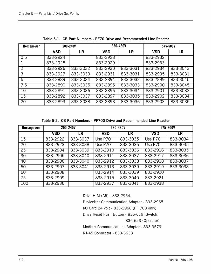
Drive HIM (A5) - 833-2964.
DeviceNet Communication Adapter - 833-2965.
I/O Card 24 volt - 833-2966 (PF 700 only)
Drive Reset Push Button - 836-619 (Switch)
836-623 (Operator)
Modbus Communications Adapter - 833-3579
RJ-45 Connector - 833-3638
Table 5-1. CB Part Numbers - PF70 Drive and Recommended Line Reactor
Horsepower 200-240V 380-480V 575-600V
VSD LR VSD LR VSD LR0.5 833-2924 833-2928 833-29321 833-2925 833-2929 833-29332 833-2926 833-3032 833-2930 833-3031 833-2934 833-30433 833-2927 833-3033 833-2931 833-3031 833-2935 833-30315 833-2889 833-3034 833-2894 833-3032 833-2899 833-30457.5 833-2890 833-3035 833-2895 833-3033 833-2900 833-304510 833-2891 833-3036 833-2896 833-3034 833-2901 833-303315 833-2892 833-3037 833-2897 833-3035 833-2902 833-303420 833-2893 833-3038 833-2898 833-3036 833-2903 833-3035
Table 5-2. CB Part Numbers - PF700 Drive and Recommended Line Reactor
Horsepower 200-240V 380-480V 575-600VVSD LR VSD LR VSD LR
15 833-2922 833-3037 Use P70 833-3035 Use P70 833-303420 833-2923 833-3038 Use P70 833-3036 Use P70 833-303525 833-2904 833-3039 833-2910 833-3036 833-2916 833-303530 833-2905 833-3040 833-2911 833-3037 833-2917 833-303640 833-2906 833-3040 833-2912 833-3038 833-2918 833-303750 833-2907 833-3041 833-2913 833-3039 833-2919 833-303860 833-2908 833-2914 833-3039 833-292075 833-2909 833-2915 833-3040 833-2921100 833-2936 833-2937 833-3041 833-2938
5-2 Part No. 750-198

Chapter 5 — Parts List / Drive Set Points
Table 5-3. PF400 Drive and Recommended Line Reactor
* Need conduit kit for NEMA 1 enclosure rating
833-3094 Conduit Kit, no DeviceNet
833-3095 Conduit Kit, w/DeviceNet
PF400 DeviceNet Communication Adapter - 833-3096**
PF400 DeviceNet Comm. Adapter Cover - 833-3097**
** Modbus communication standard on PF400
Horsepower 200-240V 380-480VVSD LR VSD LR
7.5 833-3075* 833-3035 833-3083* 833-303310 833-3076* 833-3036 833-3084* 833-303415 833-3077 833-3037 833-3085* 833-303520 833-3078 833-3038 833-3086* 833-303625 833-3079 833-3039 833-3087 833-303630 833-3080 833-3040 833-3088 833-303740 833-3081 833-3040 833-3089 833-303850 833-3082 833-3041 833-3090 833-303960 PF700 833-3091 833-303975 PF700 833-3092 833-3040100 PF700 833-3093 833-3041
Part No. 750-198 5-3

Chapter 5 — Parts List / Drive Set Points
Table 5-4. Drive Set Points and HAPS Range (all values in inches W.C.) CB Boilers
Table 5-5. Drive Set Points and HAPS Range (all values in inches W.C.) CBLE Boilers
Horsepower High Fire Windbox Pressure HAPS Range50 8.7 3-2160 9.5 3-2170 10.5 3-2180 11.2 3-21
100 8.5 3-21125 11.1 3-21150 13.8 3-21200 20.5 12-60250 8.5 3-21300 12 3-21350 15.5 12-60400 7 3-21500 11 3-21600 14.2 3-21700 18.5 12-60800 25 12-60
60ppm 30 ppm 25 ppm
Boiler HP HF WB Press.
HAPS Range
HF WB Press.
HAPS Range
HF WB Press.
HAPS Range
125 8.8 3-21 16 3-21 7.1 3-21150 11.8 3-21 12.2 3-21 12.5 3-21200 19.4 12-60 19.8 12-60 20.9 12-60250 TBD 3-21 14 3-21 15.6 3-21300 TBD 3-21 18.6 12-60 23.7 12-60350 17.3 12-60 22.2 12-60 25.4 12-60400 TBD 3-21 7.7 3-21 7.3 3-21500 9.4 3-21 11.6 3-21 12.8 3-21600 12.1 3-21 16.2 12-60 TBD 12-60700 16 12-60 19.6 12-60 TBD 12-60800 23 12-60 27.7 12-60 TBD 12-60
5-4 Part No. 750-198

Chapter 5 — Parts List / Drive Set Points
Table 5-7. Drive Set Points and HAPS Range (all values in inches W.C.) 4WI Boilers
Table 5-6. Drive Set Points and HAPS Range(all values in inches W.C.) CBW Boilers
Boiler Horsepower High Fire Windbox Pressure HAPS Range100 7.3 3-21125 8.2 3-21150 11 3-21200 16.5 3-21250 7.5 3-21300 11 3-21350 14 3-21400 17.5 12-60500 10 3-21600 13 3-21700 16.5 12-60800 21 12-60
60ppm 30 ppmBoiler HP HF WB Press. HAPS Range HF WB Press. HAPS Range
100 6.2 3-21 7.1 3-21125 8.6 3-21 13.8 3-21150 6.8 3-21 9.6 3-21200 14 3-21 18.6 12-60250 13.7 3-21 14.2 3-21300 18.5 12-60 18.8 12-60350 13.8 3-21 16.3 12-60400 17.5 12-60 22.2 12-60500 12.4 3-21 14.5 3-21600 16 12-60 20.3 12-60700 16.3 12-60 22 12-60800 23.5 12-60 28 12-60
Part No. 750-198 5-5

e-mail: [email protected] Address: http://www.cleaverbrooks.com