air-cooling methods for gas-turbine combustion systems
TRANSCRIPT

R O Y A L " '~" " ' ~ ~' ~:'7- " ~ ' - , , *~ ' " - ~ - ~ ' - " - ' - ~ ' ~
B EL ~-ORD.
MINISTRY OF SUPPLY
R. & M. No. 3110 (I¢,~)
A.R.O. T~hnleal l~)Imrt
• A E R O N A U T I C A L R E S E A R C H C O U N C I L
R E P O R T S A N D M E M O R A N D A
Air-Cooling Methods for Gas-Turbine Combustion Systems
F . J . BAYLEY, M.Sc.
© Crown copyrigAt z959
LONDON : H E R MAJESTY'S STATIONERY OFFICE
I959
TW'ELVE SHILLINGS NET

Air-Cooling Methods Combustion
for Gas-Turbine Systems
F. J. BAYLEY, M.Sc.
COMMUNICATED BY THE DIRECTOR-GENERAL OF SCIENTIFIC RESEARCH (AIR), MINISTRY OF SUPPLY
Reports Memor nd No. 31 I O*
dugust, 19 51
Summary. Thi s paper presents an account of the whole of the work which has been done at the National Gas Turbine Establishment on the problem of air cooling gas-turbine combustion systems. Each of the different methods, of wall cooling is discussed separately and the theory and mechanism of the cooling process is developed from first principles. Certain of the methods have been the subjects of experimental investigations and in such cases a brief description of the test arrangements is given and the results are analysed arid discussed. Sufficient information is given to enable any of the various methods to be applied to practical wall-cooling problems and, in a conclusion to the report, their relative advantages and disadvantages for different gas-turbine applications are considered. I t is shown that ' swea t ', or effusion:cooling, is by far the most effective and efficient method, while the use of ' louvred ' surfaces represents the nearest practical approach to this ideal which is possible while suitable porous materials remain unavailable. The remaining methods (convective cooling by external airflow, localised air injection to form a protective blanket of coolant, and a combination of these two), are all less effective, but provide means whereby conventional combustion systems may be conveniently cooled without the need for porous materials or the weight increases associated with louvred walls.
1. Introduct ion.--The advantages to be gained by the use of higher gas temperatures in internal-combustion turbines are now well established and have been comprehensively dealt with in the literature. Equally well established, however, are the difficulties associated with the use of these higher temperatures, and considerable research effort is going into attempts to solve them. The turbine, especially the highly stressed rotor blades, has naturally been the object of most of this effort, but a component which has hitherto received much less attention has been shown by recent experience to present difficulties almost as critical as those of the turbine. This component is the combustion system.
I t follows from the arrangement of a typical gas-turbine combustion system tha t the flame tube will be subjected to temperatures considerably h ighe r than prevail at the turbine inlet, and although not highly stressed, experience has shown that severe distortion and even complete tailure of flame tubes can be expected in periods of less than one thousand hours. While this is of less importance in aircraft-engine practice, where frequent complete overhauls and renewal of major Components are usual, it makes some form of cooling essential for the combustion systems of industrial gas-turbine plant required to operate continuously and reliably for 10ng periods.
Air appears as the logical coolant for gas-turbine combustion systems, and its use is assumed in each of the wall-cooling methods which are discussed in this paper. There is always an excess available over the amount of air required to burn efficiently the fuel in the primary zone of a combustion chamber, and a proportion of this may be used most conveniently for cooling purposes. The main advantage to be gained by so doing is that no heat is lost from the main working cycle
* Previously published as C.P. 133.

of the engine, as is necessarily the case with, for instance, water-cooling. The gas temperatures associated with the air-cooling system may be so arranged that after the last of the coolant has mixed with the main stream, the resultant temperature corresponds with the maximum acceptable to the turbine.
The several alternative methods of achieving wall cooling are considered separately in the text which follows. I t is assumed in all cases that the necessary airflow is independently metered, and this will have to be arranged by the designer of a particular system, who must ensure tha t the fluid static-pressure drops in the coolant and the main stream, from the initial point of separation to where they finally merge again, are equal.
2. Convective Cooling by External A ir f low. - -This method of cooling is the most simple and convenient to arrange and is commonly used. I t is especially suitable for 's traight-through' combustion-chamber flame tubes, in which the dilution air is made to flow in an annular passage, one bounding wall of which is the surface to be cooled. There is a convective heat-transfer process between the air and the hot wall and the latter attains an equilibrium temperature which is dependent upon tile ratio of the heat-transfer rates upon its two sides. The cooling-air passage need not necessarily be annular and, in fact, is only so in the case of the cylindrical combustion chamber, but it is very conveniently formed between the flame tube or a similar liner and an outer pressure casing, the gap being dimensioned by pressure-drop considerations as shown later.
2.1. Theory of Operation.--The temperature of the wall at any point in the cooling system, assuming infinite radial conduction and none in a longitudinal direction, is given by the equation •
h4F4( O~, - - 04) : h~F~( T~ " 0~) . . . . . . . . . . . (1)
If the heat-transfer coefficients are referred to the base surface, then F~ - - F g : F , say, in which case we may write •
h4(0 - o2 = . . . . . . . . . . . . . (la)
The temperature of the cooling air, 0~, is a variable which depends upon the thermal capacity of the airflow and the heat-transfer rate. Consider a short length of tile system, ~x, distant x from the origin where 04 : T~. The heat balance may be written down as
C~W4 ~ 0o = h4 ~F (0o -- 04) . . . . . . . . . . (2)
In most cases F is a linear function of x, the constant being the perimeter, which for the cylindrical surface is nd. Thus in the limit, for the cylindrical surface, equation (2) becomes •
d O 4 - - K ~ ( O ~ - 04) . . . . . . . . . . (2a) dx
where
Substituting for 0~ from equation
where
Therefore
h4~d K1 -- CpW4"
(1 a) gives •
dO ~ K1 K1 dx -- 04 + T~ ' (2b)
K ~ : I + h4
K 1 ~d h flg KE - - ho +
h '~d - - CpW4'
2

where h' is the overall heat-transfer coefficient between the hot gas and the cooling air and is given by :
1 1 1
Integrating equation (2b) with the aid of the factor exp (xK1/K2), and applying the end condition that 04= T, when x = 0, gives the solution :
T , - 04 (3) = " e x K 1 / K 2 . . . . . . . . . . . . .
Thus, the wall temperature at any point in a system may be evaluated by first calculating the air temperature according to equation (3) and then substituting the result into equation (la).
2.2. Estimation of the Heat-Transfer Coefficients in the System.--If a calculation is to be made according to the theory set out above, then a knowledge is required of the heat-transfer coefficients on tlhe two sides of the wall to be cooled.
Unless experimental results are available from tests made with exactly similar conditions of flow, it is impossible to make other than an approximate estimate of the heat-transfer coefficient between the hot gas and the wall. This is especially the case with combustion-chamber flame tubes in which there are the complicating effects of flame radiation and often violent swirl, and a note about heat-transfer conditions in these is given in Appendix I. However, where developed turbulent flow may be expected as in long uninterrupted lengths of ducting, the well-known standard formula, which is reproduced here may be used to predict the heat-transfer coefficient •
h < _ 0.02 (<C] °'~ . . . . . . . (4) \ #g/ . . . . .
This equation assumes that the Prandtl number, g~tCp/~, is constant at 0.71, the value for air.
The problem of estimating the heat-transfer coefficient on the air side is usually less severe. If the equivalent diameter, de, defined as
de : 4 × Area available for flow Wetted perimeter
is used, and the passage length is large compared with the value of this parameter, then equation (4) may be applied to conditions of turbulent flow. There is some difference of opinion as to whether the total wetted perimeter or the heated perimeter alone should be used to define the equivalent diameter in the case of the annulus having one wall only heated, but the little experimental evidence that is available indicates that the former procedure is correct. In any event, the form of equation (4) is such that the difference between the heat-transfer coefficients predicted by the two definitions of the equivalent diameter is only about 15 per cent.
Equation (4) may be used with reasonable accuracy down to values of the Reynolds number, d,G/izg, of about 2,000, but as this lower limit is approached the estimated values of the heat- transfer coefficient become increasingly liable to error. Under such conditions the Nusselt number hde/2 becomes a function of the length/diameter ratio and other variables, but if the theoretically calculated values of this for truly laminar flow, as given in Ref. 3, are used when the Reynolds number is less than 2,000, and equation (4) used above this value, then the estimated heat-transfer rate will be on the conservative side, since it is likely to be increased unpredictably by natural convection and entry-length effects.
2.3. The Use of Fins or Secondary Surfaces.--To increase the rate of heat transfer on the cooling- air side of the system, use may be made of fins, or secondary surfaces, which increase the effective area for heat exchange. Secondary surfaces are not one hundred per cent efficient, that is to say, the addition of a fin area equal to the base area does not double the rate of heat transfer,
3 (74s14)

because the temperature drop that must occur along the fin if heat is to be conducted away from its base, reduces the potential available to produce heat transfer. To allow for this effect, use is made of a factor ~, which is defined by :
Average temperature difference over the extended surface
Thus, if to a base surface F, fins of area F / a r e added, then equation (1) may be written as :
h~(F + SF/)(O~ -- o4) = h , f ( T , - 0~) . . . . . . . . . . . . . (lb)
I t is often more convenient to consider that an apparent air-side heat-transfer coefficient, hi', is applying over the base area F, in which case the apparent coefficient is given by :
h/' F + 4 F s - - F h . . . . . . . . . . . . . . . (S )
- - P / + 2¢Yl h~. . . . . . . . . . . . . . (ha) P I
The value of ~b depends upon the coefficient of thermal conductivity of the fin material, its dimensions and the heat-transfer coefficient between it and the air. Gardner, in Ref. 4, has calculated values of ~ for various shapes and sizes of fin, and Fig. 1, which is taken from this Reference, shows the variation of ~ with, a parameter which includes all the relevant variables for the usual case of a fin of constant cross-sectional area.
2.4. The Pressure Drop through the System and its Effects.--A limit to the extent to which an external flow of air may be effective for cooling is usually set by the pressure drop allowed in the main combustion system, remembering that the static-pressure loss in the coolant must always be accompanied b y an equivalent loss in the main gas stream.
The frictional pressure drop occurring along the cooling-air passages under conditions of turbulent flow is given by the formula, at tr ibuted to Blazius :
0"316 1 ~V ~ L A P - - ReO.2~ 2 g do" . . . . . . . . . . . . (6)
This is additional to the acceleration pressure loss which varies with the square of the air velocity. Thus, it follows that the pressure loss associated with the cooling system is approximately proportional to the mean air velocity raised to some power between 1.75 and 2. Since, from equation (4), the heat-transfer coefficient varies with the 0.8 power of the velocity, any a t tempt to improve the cooling effect by an increase in velocity leads to a disproportionate increase in pressure loss*. This implies tha t in certain cases, especially in high-temperature combustion systems where large cooling effects are necessary, the pressure drop associated with the required cooling effect is likely to exceed that allowed by engine performance considerations.
3. The Use of 'Louvred' Surfaces for CooZingt.--In the previous Section it was shown how, by the use of secondary surfaces to obtain a greater effective area for heat transfer on the air side Of a cooled wall, the cooling effect could be increased. The ' louvred' wall works on an extension of this principle, since the method of construction is such that the area for heat extraction is much larger than that available for heat input from the hot gases. The surface to be cooled is so made tha t there are many small independent passages along which the cooling air may flow
* Should the flow be laminar, that is, the Reynolds number less than about 2,000, the term (0.316~Re °'~) in equation (6) should be replaced by C/Re, C being a constant. This implies that the pressure drop varies linearly with the velocity, but since the heat-transfer coefficient theoretically would remain constant, the conclusions of the argument which follows remain unaffected. Values of C are given in ReI. 3 for differently shaped passages, and for the annulus and narrow gap it is 96.
This method of construction for cooled flame-tube walls is the subject of British Patent 642,257, held by the ' Shell ' Refining and Marketing Co., Ltd.
4

radially, finally emerging to mix with the main gas stream. This may be achieved by constructing a circular flame tube, for instance, from a series of annular discs, clamped so that there is a gap between each pair to form the air passages. The inner circumferences form the bounding wall of the main gas stream. A detailed description of a combustion chamber with the flame tube so constructed is given in Ref. 5, although in this case, to reduce the number of rings required to make up the flame-tube length, they are stamped to form conical frustra, and hence the passages are inclined to the true radial direction.
3.1. T h e o r y o f O p e r a t i o n . - - T o determine the temperatures in such a system, in which tempera- ture variations through the fin thickness are neglected, consider an elementary length of fin which is distant x from the point of entry of the cooling air to the passages. There is a balance between the heat convected to the air over the length being considered and that conducted into and out of it, which may be written as :
-
d~.O~ = ~,C~ ~ ax . . . . . . . . . . . . . (7)
If f is the heat-transfer area pe r unit length of fin, it may b e regarded in most cases as independent of x without serious error.
Thus rewriting equation (7) we get :
d~O~ . . . . . . . (7a) h o f ( - oo) = -dx . . . . . . .
Now consider the heat balance of the air in passing the length 0x
CpW~ OOa = h J ( O ~ - - 0~) Ox . . . . . . . . . . . . . (8)
W~ is, in this case, the flow of air per passage. In the limit, equation (8) becomes :
C , W o doo . . . . . . (8a) 0 ~ = 0 ~ + h J d x . . . . . . .
Substi tuting in equation (7a) for 0~ from equation (8a) and writing/£3 for @ W J h f and K~ for c,wJ we get
d~O d~O ~ dO ~ K3 ~ + dx--~ - - K4 ~ - = 0 . . . . . . . . . . . . . . . . . ( 9 )
The solution of this differential equation has the form
0~ = A + A1 e~l" + A~ e"~ ~ , . . . . . . . . . . (10)
where a = a~, as are the roots of the auxiliary equation
K . a ~ + a -- K 4 = 0 . . . . . . . . . . . . . (11)
and A, A1, As, are constants of integration. Substituting in equation (8a) for 0~ from equation (10) gives the complete solution for tile wall temperature at any point x as :
0~ = A + A~(1 + a~K3) e~ ~ + A~(1 + a~K~) e~ ~ . . . . . (12)
5

To apply this equation" to a given design we need three separate end conditions with which to evaluate the constants of integration, A, A1, As. The three most convenient conditions are :
(a) At the hot end of the fin, at x ---- L, all the heat passes by coriduction through the surface, i.e.,
a ° ° l - (12a) H~
-d-#j ~=L ~f,,, . . . . . . . . . . . . . . . . .
H~ is the heat input to the inner surface of each fin from the hot gases.
(b) At en t ry to the passages, x ---- 0, the cooling air temperature is known, i.e.,
T~ = A + A~ + A s . . . . . : . . . . . . . (12b)
(c) If heat losses from the cold side of the system are neglected, then the air receives H~ heat units per second in its passage through the wall, and knowing its mass-flow rate and specific heat, the exit temperature is known, i.e.,
H~ A + A1 e ~IL + As e ~L (12c) T~ + W~Cp - - " . . . . . . . . . .
In using this method of calculation it will b e found most convenient t o obtain the values of A, A1, As, in terms of the unknown He. Then since it is the value of 0, at the hot end of the fin, at x - ~ L, say, T~, which is usually required, a final equation can be obtained which has only T, as an unknown since we have :
H , - ~ h~F~(Tg- T,) . . . . . . . . . . . . . (t3)
F~ in this equation is, of course, the effective area available for heat transfer from the hot gases to each fin.
3.2. Estimation of the Heat-Transfer Coefficients in the Sys tem. - -The evaluation of the heat- transfer coefficient on the gas side presents difficulties similar to those described in the previous Section, With the additional complication of the unknown effect upon the convective heat-transfer process of the discontinuous nature of the wall and of the injection of the cooling air. With the lack of more precise experimental evidence, all that can be done to allow for the effects of these factors, is to assume that they cancel each other out.
In the air passages, with the necessarily small gaps, the air flow is likely to be laminar in which case the Nusselt number should be taken as 8.2, which is the theoretical value given by Smith in Ref. 3. Should the Reynolds number exceed 2,000, as previously described, equation (4) may be used, with the equivalent diameter d,, taken as twice the passage height.
3.3. Some Calculated Results.--Fig. 2 shows the results of some calculations made according to the theory described in this Section, for a typical hot-gas duct similar in construction to tha t described in Ref. 5. The effect of a varying air flow upon the maximum temperatures reached by the wall when constructed from either stainless steel or copper is shown by Fig. 2a, while the effect of the different thermal conductivities of these two metalsupon thetemperature distribution in the system is shown by Fig. 2b. Although the maximum temperature reached by the copper wall (coefficient of conductivity = 216 C.H.U./hr.ft. C), is less than that obtained withstainless- steel fins (coefficient of conductivity ---- 11 C.H.U./hr.ft.°C), the metal temperature for 80 per cent of the fin length is actually higher.
3.4. The Pressure Dro15 through the Sys tem.- -To estimate the pressure drop associated with the flow of air through the passages in a louvred wall, equation (6) may be used with the factor C/Re replacing 0" 316~Re °'~ if the Reynolds number is less than 2,000, as explained in the footnote to Section 2.4. Unlike the difficulty met with in the method of cooling discussed in the previous Section with regard to pressure drop, the problem with the louvred wall is usually to make the pressure drop sufficiently large for there to be any control of the distribution of the air over the surface to be cooled. If the gaps between each element of the wall are too big, and the throughway ratio excessive, the pressure drop across the wall is so low as to be of the order of that in the main
6

gas stream resulting from its viscid flow down the duct. In such a case, most of the air will flow through the wall at t h e downstream end of the duct, While the upstream surface will receive an inadequate supply of coolant. I t is usually necessary with practical louvred walls to use far more air than would really be necessary for cooling, were it possible to distribute a lesser amount uniformly over the surface.
4. The Use of Porous Watls.--'Sweat' Cooling.--With the louvre method of construction for a cooled wall, as discussed in the last Section, a surface was obtained which contained a number of passages for cooling-air flow, in which a convective heat-transfer process removed the heat that was conducted back through the metal of the wall from its hot inner surface. The porous wall may be considered as working on the same principle carried to its ultimate extreme, i.e., the pores in the wall provide the many small passages, and hence a very large area over which heat transfer between the wall and the cooling air may take place. In addition, since there are so many small passages scattered uniformly over the surface of the wall, the air jets emerging from each immediately coalesce to form a continuous cool boundary layer which, under certain conditions, drastically reduces the rate of heat transfer from the hot gas, and so adds to the cooling effect.
The earliest experimental evidence of the effectiveness of 'sweat ' cooling, as cooling by means of porous walls is commonly called, was published by Duwez and Wheeler in Ref. 6. Their porous test section was, however/only I. 5 in. long by 1 in. diameter and the need was therefore felt for some additional experimental data obtained from tests on a porous-walled duct comparable in size to the gas-turbine components to which it was hoped eventually to apply the technique of sweat cooling. A brief description O f these tests and the apparatus used for them is given below.
4.1. Test Arrangements a~d Results.--The arrangement of the porous-walled test section is shown by Fig. 3. I t was supplied with hot gas at varying temperatures from a combustion chamber some 8 ft upstream, while t h e cooling air supply was led to the airtight box which surrounded it, and which served to damp out pressure fluctuations transmit ted from the blower. The airflow rate was measured by all independent standard orifice plate, and the gas mass flow was obtained by difference between the air mass flow and the total value as given by a measuring section in the main supply line from the blower. The gas temperature was measured by means of a single shielded chromel-alumel thermo-couple just upstream of the test section, while the two used for measuring the air temperatmes are shown in the sketch.
The porous duct itself, which was 6.4 in. in diameter and 21 in. long, was rolled from two sheets of a porous bronze, which was originally developed as a filtering medium, and which
therefore left much to be desired in the w a y of strength and resistance to high temperature. The necessary joints in the duct were made by brazing, a method which was not very satisfactory in that it led to appreciable areas of the surface becoming blocked ,near the joints, and the inevitable overheating caused embrittlement of the m e t a l . The line of eleven thermocouples used to measure wall temperatures, and which were plugged into the wall in the manner shown in the small sketch in Fig. 3, was placed diagonally opposite the longitudinal brazed joint, so tha t the non-porous, and hence uncooled, areas should have as little effect as possible upon the .observations of wall temperature.
In the course of the experiments, readings of wall temperature were taken for various gas stream temperatures and gas and air mass flows. The results are shown plotted in Fig. 4 as cooling efficiency vs. the ratio, cooling-air mass flow per unit surface area/gas flow per unit duct crosssectional area, a correlation suggested by Duwez and Wheeler in Ref. 6. The cooling efficiency, ~, is defined by
~ = r g - - r ~ '
0,' being the mean of the observed wall-temperature readings, those at each end of the duct being neglected, however, because of the large effect Upon them of the uncooled areas under the flanges.
7

The gas temperatures used in the tests ranged between 300 and 700 deg C, while the main-gas- stream Reynolds numbers were between 110,000 and 220,000. Over this ~-ange the correlation suggested by the authors of Ref. 6 is quite successful, as is shown by Fig. 4, from which it is apparent how easily cooling efficiencies of the order of 90 per cent are obtainable under the conditions of the tests, with quite small air mass flows.
4.2. Analys is and Discussion of the Test Resul t s . - -S ince there is a very large area for heat transfer within the wall of a porous duct, and since the airflows are quite small, it is justifiable to assume tha t in passing through the pores, the cooling-air temperature is raised to that of the inner surface of the wall. By making this assumption and knowing the rate of cooling-air flow, it is possible to calculate the heat-transfer coefficient between the gas stream and the porous duct, but any errors that are incurred by so doing will be such as to make the coefficients obtained higher than those actually prevailing.
The results obtained with the porous-bronze duct in the test rig which has been described, were analysed in this way, and they showed that the Nusselt number, based on the mean of the wall and gas temperatures, was independent of the rate of cooling-air flow, and for a given main- stream Reynolds number, sensibly constant at a value considerably less than tha t which would be predicted for similar conditions of developed turbulent flow.. Analysis of the tests of Ref. 6 yielded a similar result, as is shown by Fig. 5, but the reduction in Nusselt number is not so marked, and in fact, a t the higher Reynolds numbers is negative due probably to the extension of entry-length flow conditions to include that part of the walt in which was inserted the single thermo-couple used to measure the cooled surface temperature.
Now with the assumption that the cooling-air flow of Q lb/sec ft ~ is raised to the inner wall temperature we have tha t the heat input to the wall is •
I-Z,' = QC/o ' - T . ) ,
where H / i s the heat flow per unit inner-wall surface area. But also we have tha t •
H , ' = h,(Tg-
From these two equations we get :
-
O~'-- To-- hg
= K 5
But by definition the cooling efficiency, ,/, is
Zg -- Tg
Thus the cooling effect in a porous wall is an are neglected.
(say).
given by
- - T ~ J
K5 - K5 + 1 . . . . . . . . . . . . . ( 1 3 )
explicit function of Q/hg, if variations in specific heat
Now suppose it is assumed that the rate of heat transfer to a porous wall is defined by an equation of the form •
N u = B Re" . . . . . . . . . . . . . (-14)
8

which implies tha t the rate of airflow has no effect upon the Nusselt number, as is suggested by the experimental results. Then we have that :
K5 = CpQ h~
_ CpQd N u 1L
_ CpQd B Re" ~L
_ c ,qa Re1_ , , B Re ~L
CpQd#gg Re~_,, - - BdGaL
_ CpgQ #g Re~_,, (15) BG ~L . . . . . . . . . . .
This means tha t the cooling effect in a porous wall is an explicit function of the parameter :
Q ~g Re1-,,. G 2L
A plot of the calculated Nusselt numbers against the corresponding Reynolds numbers from the tests of Duwez and Wheeler yields, on logarithmic co-ordinates, a straight line with a slope of unity, showing • to be one, but the author 's (N.G.T.E.) results, while less conclusive because of the smaller range of Reynolds numbers covered, indicate the value of n in these tests to have been about two. Thus from these results and equation (15) it would be expected that the cooling effect should correlate against :
Q #g Re -~ (N.G.T.E. tests), G ,~L
Q ~g (Duwez and Wheeler's tests). G 2L
In actual fact the value of 2 for the index n in the N.G.T.E. tests proved to be too high and 1.8 was taken as the more exact value ; thus the parameter becomes in this case :
Q/~g Rei l .8 . G ;*L
The curves obtained by plotting the observed cooling effects in the respective test series against the appropriate parameters are shown by Fig. 6, where it will be observed that the degree of correlation is remarkably good in both cases. This appears to confirm that an equation of the form of equation (14) completely defines the rate of heat flow to a cooled porous wall, at least for air injection quantities of the order of those used in both test series which were sufficient to maintain the boundary layers at the maximum thickness corresponding to the flow conditions, as explained below.
Now it has been shown that the cooling efficiency, ~, is given by •
K5 ~ / - - K s + 1 ' " . . . . .
and
K5 = C~g Q #g Re1_,, " B G2L
(13)
(is)

Thus from the curves of Fig. 6 it is possible to calculate the values of B in equation.(15). The values of this constant to which the lines drawn through the results of the two series of tests correspond are 4.72 × 10 .8 for the N.G.T.E. tests and 3.58 × 10 .3 for those of Duwez and Wheeler. In other words the rate of heat transfer between the hot gases and the porous duct in the two cases can be represented b y "
N.G.T.E. tests • N u = 4.72 10 .8 Re 18,
Re Duwez's and Wheeler 's tests • N u = 3.58 100~" ""
.(16)
(17)
The discrepancy between the rates of heat transfer and the variation of these with Reynolds number in the two test series is believed due to the difference in sizes of the respective porous ducts. Now it is shown in Appendix II that if h e is the heat-transfer coefficient between a moving gas stream and a surface, between which there is a laminar boundary layer of thickness ~ and conductivity 2L, through which heat transfer can take place by conduction alone, then h~ i s given by
1 1 + h c ' • . . . . . . . . . (a.6)
where hc is the true convective heat-transfer coefficient as is used in Reynolds analogy. This heat-transfer coefficient, h~, is approximately a linear function of Reynolds number and it is probable that in Duwez's and Wheeler 's short test section there was no effective boundary layer due to the effects of both the thermal and fluid entry length, and therefore the overall coefficient, hg, was virtually equal to he. In the long porous duct used by the author, however, in which developed tmbulent-flow conditions prevailed, it is believed tha t the injection of the cooling air led to the formation of a relatively thick boundary layer, the equilibrium thickness of which was a function of the gas-stream Reynolds number alone, and it is the nature of this function tha t determines the manner of variation of hg, and therefore of the Nusselt number, with the Reynolds number. Although no quantitative values of he and ~ are available, if the term ~hJ,~L is large compared with unity, for the observed variation of Nusselt number with Reynolds number as given by equation (16) to be correct, Would require that the boundary-layer thickness in a sweat~cooled duct is inversely proportional to the 1.8 power of the Reynolds number under conditions of developed turbulent flow.
The foregoing analysis of the sweat-cooling process has, of necessity, been somewhat empirical because of the complexities of the transfer processes involved. There have been, however, several theories of sweat cooling published, all of which involved certain simplifying assumptions. Rannie, in Ref. 7, for'example, has developed a theory of porous-wall cooling which assumes tha t the laminar boundary-layer thickness is the same over a sweat-cooled wall as for flow through an ordinary pipe. The results of this theory are shown on Fig. 4, in which the predicted cooling effects are considerably less than those observed in the tests made by the author a n d described in this paper, and this discrepancy appears to confirm tha t the injection of the air through the wall under developed turbulent-flow conditions does result m an appreciable thickening of the laminar boundary layer.
Grootenhuis and Moore, in Ref. 8, give a theory which they have developed by solving, by an approximate method, the fundamental equations of fluid motion with the boundary conditions appropriate to flow over a porous fiat plate thrcugh which air is injected. I t will be noted that these authors use the parameter (V~/Vg) ~ Re to correlate their calculated cooling effects, which is equivalent to (V~/V~)v'Re. This parameter is equal to the parameter given by equation (15) with n = 0" 5 for the isothermal case and the value of one-half for n corresponds to the theoretical figure for laminar flow over a plate, which is the condition assumed by the authors. In Ref. 9 Grootenhuis and Moore have compared the values of sweat-cooling effects which their theory predicts, with the experimental observations of Duwez and Wheeler, and the author, and although their calculated curve makes a fair mean through both sets of results (between which, upon the
10

correlation of this report, there is a large discrepancy) the scatter of the points abou t t he curve, especially in the horizontal direction, is so large as to make inconclusive any comparison made between the theoretical and experimental values.
4.3. Sweat Cooling in Practice.--While the results with the test rig previously described may be considered as applicable to sweat-cooled walls under conditions of developed turbulent flow, and in which radiation is negligible, these conditions rarely occur in gas-turbine combustion systems. They may, however, be assumed, in certain cases, in turbine inlet sections where there is likely to be a stable boundary layer such as is associated with accelerating flow.
In general, however, the ideal conditions that prevailed in the test rig do not apply in prac[ical problems. In combustion-chamber flame tubes in which the highest cooling effects are needed, there is usually the violent swirl used to stabilise the flame, and often the effects of radiation from the burning fuel to be taken into consideration. After the completion of the tests upon the porous-bronze duct which have been discussed, this was operated as a combustion chamber by inserting a flame stabilising baffle at its upstream end through which fuel was injected and burnt within the duct. I t was not possible to obtain exact results of quantitative value from the rig under these conditions, but the measurements that were made indicated that about two and a half times as much air was required for equal cooling effects as compared with the original tests. This increase may be regarded as resulting from a larger convective rate of heat transfer, since the flame within the duct was not very luminous, being of the type usually associated with distillate fuels, and radiation could therefore be neglected. Where radiation is likely to be appreciable, its effect may be taken into account by adding, the rate of radiant heat transfer to that given by equation (15), or a modification of it to allow for the effect of swirl, and equating the heat input to that picked up by the air in its passage through the wall, assuming that its temperature is raised to that of the inner surface, i.e.,
N u = 4 . 7 2 10 -8 Re 1"8 . . . . . . . . . . (16)
for developed turbulent flow. If the factor of 2.5 is accepted to allow for the effect of swirl as Observed in the reported tests on the porous-bronze duct when operating as a flame tube, then equation (15) can be modified to :
N u = 1.2 10 -7 Re 1"s . . . . . . . . . . . . (16a) Thus
h g = 1.2 10 -7 Re181i, d"
The heat input b y convection, He, is thus
Hc = h g ( T ~ - T~)Fg.
By radiation, the heat input H , is given by
H, = h , ( T g - T~)Fg
as explained in Appendix I. Therefore the heat balance to be solved for T~, or Q, whichever is required is :
H~ + H, = FgCpQ(Tw- T~) . . . . . . . . . . . (18)
This method of calculation is, of necessity, only empirical and liable to considerable errors from inexact estimate of the requisite heat-transfer coefficients, but it may be used to assess approxi- mately the cooling effects likely to be experienced with porous walls working under conditions similar to those described.
The greatest single difficulty in the way of the universal application of sweat cooling is the lack of a suitable porous metal having the necessary properties of tensile and fatigue strength, ductility, resistance to moderate temperatures and controllable permeability. These requirements
11

are of course formidable, but considerable progress has been made towards overcoming them, and the rewards to be gained from so doing will warrant the effort required. However, the metallurgical problems associated with the technique of sweat cooling are outside the scope of this report.
4.4. The Pressure Dr@ i~ Porous Walls .--The pressure drop for conditions of laminar flow through a porous material is given by D 'Arcy's equation which is given in Ref. 10 as •
QL . . . . . . . . (19) P1 ~ - Po ~ - 144 2P0/* . . . . .
P1 and P0 are the air pressures in lb/ft 2 on either side of the porous wall and ~ is the coefficient of permeability and has tile dimensions of an area, usually square inches. Where turbulent flow occurs (no exact criterion for the point of transition appears to have been decided), a more complicated and general equation by Rose in Ref. 11 should strictly be used, but it will be found tha t for most gas-turbine applications of sweat cooling D 'Arcy ' s equation applies with sufficient accuracy. F o r small pressure differences this equation may be simplified to :
Q L ~ ~0 . . . . . . . . (19a) AP -- 144# ' " . . . . .
from which it is apparent that the flow rate is proportional to the pressure drop.
I t has been suggested that over long periods of operation in industrial atmospheres, the permeability of a porous metal used for sweat cooling will decrease due to the deposition in the pores of solid matter previously suspended in the air. If this were to prove the case, and no successful antidote were found, it would provide a serious objection to the use of sweat cooling for many gas-turbine applications.
Tests made to determine the susceptibility of porous metals to blockage by atmospheric deposits have shown conflicting results. Observations of permeability made upon the porous- bronze duct used for the original sweat-coMing tests described in this paper, showed it to drop off rapidly during the first few hours of operation, after which it became steady at about 40 per cent of the original value. Later pressure-drop tests upon various small porous specimens in, however, a v e r y oily atmosphere, showed the permeability to drop off more and more rapidly until, finally, complete blockage occurred. These and other observations showed that the rate of blockage of a porous wall depended very much upon the nature of the particles suspended in the cooling air, and oiliness in particular was a thing to be avoided. From all the observations, also, two other important, and general, observations could be drawn. Firstly, that desposits in a porous material can, in most cases, be removed by an air blast from the downstream side, and secondly, tha t a comparatively crude filter (a thickness of rag was very effective in the case of tile oily atmosphere) is sufficient to remove tile offending particles from the air stream and to prevent any decrease in permeability over long operating periods.
5. Cooling by Localised Air [email protected] object of this method of cooling is to reduce tile rate of heat transfer to a surface by creating over it a layer of comparatively cool fluid. The ideal of the laminar boundary layer through which heat transfer can take place by conduction, or radiation, only, as was achieved with a porous wall, cannot be attained by injection through orifices of a practical size in an ordinary metal wall. However, by careful choice of injection velocities and arrangements of the inlet ports, it is possible to form a protective blanket of a mixture of cooling air and hot gas which, although moving with the main stream, does restrict tile convective rate of heat transfer to the surface over which it is formed.
The most effective way of creating this 'boundary layer ' , as it is called, although the term does not apply in its strict aerodynamic sense, is to inject the cooling air ehrough rows of suitable ports, arranged around the perimeter of the surface to be cooled. The layer thus formed moves down- stream over the wall of the duct, 'decaying', i.e., increasing in temperature, as it does so, as a result of a process of both mass and heat transfer from the main hot gas stream.
12

5.1. Theory. of Operatior~.--A theory of the operation of the ideal boundary layer formed by localised injection of air tMough rows of ports is given in Appendix hi, but a less rigorous alternative, which involves a major simplifying assumption, is better suited to explain the mechanism of the cooling process and to analyse observed experimental results.
Consider an elementary length of the wall to be cooled, distant x from the point of injection, and the heat balance between the heat transferred to that part of the wall and that conducted along it becomes :
dOg,x) dolt hr f Ox(OL-- 0~) = - - t ~ t f t d ( o ~ -¢- - ~ - - - ~ t . . . . . . . (20)
f is, in this case, the perimeter of the surface. Rearranging this equation gives :
OL - - O~ - - - - K 6 d20~ . . . . (20a) d x 2 . . . . . . . . .
where ~wt
K 6 - hL"
This is similar to equation (7) of Section 3, but in th is instance, to solve equation (20a), an assumption must be made as to the form of the function that 0L is of x. Now, if the mass flow of cooling air is small compared with that of the main stream, it may be assumed that, after being initially formed at some temperature, say T g - A 0, which is between the air and gas temperatures, the boundary layer will move in the direction of increasing x with its temperature approaching that of the main gas stream. It is suggested by the form of the general solution of the ideal boundary layer given in Appendix I I I that the temperature distribution along the duet follows an exponential law, and the simplest possible equation of this form satisfies the conditions assumed above, i.e.,
oL = T g - AO e . . . . . . . . . . . (21)
The use of this equation in which oc is assumed constant, to solve equation (20a), represents the major simplifying assumption that was mentioned previously, but which, however, appears to be justified by the experimental results as shown later.
The value of the boundary=layer temperature at any point, 0L, as given by equation (21), may now be substituted into equation (20a) to give :
• d20~ T ~ - A O e - ° : ' - O~ KG dx ~ . . . . . . . . . . . . . . (22)
which may be integrated to :
A O e- °:,. Tg -- O~ = A3 e'/<~G + A4 e-'/V~6 + 1 -- K---~ ~" .. .. (23)
A3 and A~ are the constants of integration to be calculated from the end conditions.
5.2. A n Experimental Investigation.--The method of wall cooling under discussion in this Section was the subject of an experimental investigation undertaken by the author. The test rig shown in Fig. 3 and described in the previous Section was used. The porous duct was replaced by one rolled from 22 S.W.G. stainless steel sheet in which were formed the differentinjection-port arrangements to be tested. Wall-temperature measurements for various conditions of air and gas flow were made with thermo-couples which were welded to the test section, beneath the lagging with which it was surrounded to reduce external heat losses from the wall to the incoming cooling air.
13
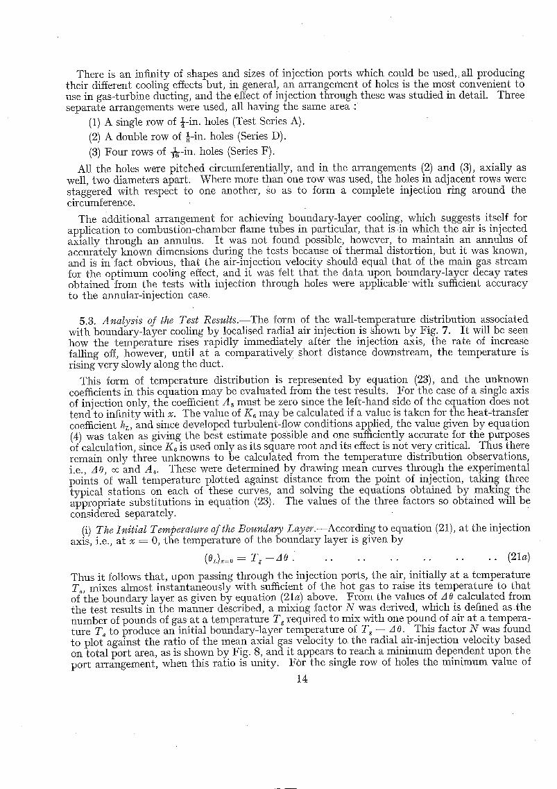
There is an infinity of shapes and sizes of iniection ports which could be used, tall producing their different cooling effects but, in general, an arrangement of holes is the most convenient to use in gas-turbine ducting, and the effect of injection through these was studied in detail. Three separate arrangements were used, all having the same area :
(1) A single row of k-in. holes (Test Series A).
(2) A double row of ½-in. holes (Series D).
(3) Four rows of n- in . holes (Series F).
All the holes were pitched circumferentially, and in the arrangements (2) and (3), axially as well, two diameters apart. Where more than one row was used, the holes in adjacent rows were staggered with respect to one another, go as to form a complete injection ring around the circumference.
The additional arrangement for achieving boundary-layer cooling, which suggests itself for application to combustion-chamber flame tubes in particular, that is i n which the air is iniected axially through an annulus. I t was not found possible, however, to maintain an annulus of accurately known dimensions during the tests because of thermal distortion, but it was known, and is in fact obvious, that the air-injection velocity should equal tha t of the main gas stream for the optimum cooling effect, and it was felt that the data upon boundary-layer decay rates obtained from the tests with injection through holes were applicable with sufficient accuracy to the annular-injection case.
5.3. Analysis of the Test Results.--The form of the wall-temperature distribution associated with boundary-layer cooling by localised radial air injection is shown by. Fig. 7. I t will be seen how the temperature rises rapidly immediately after the iniection axis, the rate of increase falling off, however, until at a comparatively short distance downstream, the temperature is rising very slowly along the duct.
This form of temperature distribution is represented by equation (23), and the unknown coefficients in this equation may be evaluated from the test results. For the case of a single axis of iniection only, the coefficient A3 must be zero since the left-hand side of the equation does not tend to infinity with x. The value of K6 may be calculated if a value is taken for the heat-transfer coefficient hL, and since developed tm-bulent-flow conditions applied, the value given by equation (4) was taken as giving the best estimate possible and one sufficiently accurate for tile purposes of calculation, since K6 is used only as its square root and its effect is not very critical. Thus there remain only three unknowns to be calculated from the temperature distribution observations, i.e., d 0, oc and A~. These were determined by drawing mean curves through the experimental points of wall temperature plotted against distance from the point of injection, taking three typical stations on each of these curves, and solving the equations obtained by making the appropriate substitutions in equation (23). The values of the three factors so obtained will be considered separately.
(i) The Initial Tempe~'ature of the Boundary Layer.--According to equation (21), at the inj ection axis, i.e., at x = 0, the temperature of tile boundary layer is given by
(0L),=0 = T~--AO . . . . . . . . . . . . . (21a)
Thus it follows that, upon passing through the injection ports, the air, initially at a temperature T~, mixes almost instantaneously with sufficient of the hot gas to raise its temperature to that of tile boundary layer as given by equation (21a) above. From tile values of A 0 calculated from the test results in the manner described, a mixing factor N was derived, which is defined as the number of pounds of gas at a temperature Tg required to mix with one pound of air at a tempera- ture T~ to produce an initial boundary-layer temperature of Tg -- A O. This factor N was found to plot against the ratio of the mean axial gas velocity to the radial air-in iection velocity based on total port area, as is shown by Fig. 8, and it appears to reach a minimum dependent upon the port arrangement, when this ratio is unity. For the single row of holes the minimum value of
14

t hemix ing factor is two, for the double row, one, and for the quadruple row, a half. The relation between these minima is qui te logical, for, if the minimum value for N of 2 is accepted for the single row of injection ports pitches at two diameters, which occupy half the circumference, then a minimum value of 1 would be expected for the double row which takes up the whole circumfer- ence, a n d a value of a half follows for the quadruple row which is equal to two complete circumferences Occupied by .injection ports.
(it) The Rate of Decay of the Boundary Layer.--After the period of mixing between the injected cooling air and the hot gas near the surface is completed, the boundary layer moves down the duct wail, increasing in temperature as it does so, according to equation (21) :
T~ --OL ---- AO e - ~ . . . . . . . . . . . . . (21)
The increase in temperature is due to heat exchange between the maingas stream and the cooler boundary layer, par t ly through further mixing and part ly as a result of the usual processes of convection and conduction. The rate of heat exchange would therefore be expected to depend primarily upon the degree of turbulence in the gas stream, and hence, for developed flow, upon the Reynolds number, and the associated rise in temperature within the boundary layer, upon tile inverse of its mass.
These expectations are to some extent confirmed by the experimental results. F ig . 9 shows - the variation of the exponential index oc, which is a measure of the rate of decay, with the mass of the boundary layer at a substantially constant Reynolds number. I n spite of the scatter, it is found that the mean line through the points is a reciprocal curve, being a straight line with a slope of minus uni ty when plotted on logarithmic co-ordinates.
The results of the laborious calculations necessary to analyse the experimental observations were very sensitive to inaccm'acies in wall temperature measurement, and this condition was greatly magnified in the case of the index oc, because of the narrow range of .values of this factor which were covered during the tests, due to the limitations in the airflow available to the test rig. However, an at tempt has been made to correlate the observed values of this decay factor with a parameter Re ~d/(N + 1)W~, and the result of so doing is shown by Fig. 10. In spite of the scatter of the points about the mean line, a distinct trend in the results is apparent. The use of this parameter involves the assumption about the linear effect of the Reynolds number upon the rate of heat transfer from the gas stream to the boundary layer, an effect which was observed in the last Section in connection With the sweat-cooling results. There is, however, no experi- mental justification for the inclusion 0f the duct diameter to allow for the effect of surface area upon the rate of decay of the boundary layer which covers it. I t appears, however, reasonable to assume as a first approximation a linear variation between the surface area and the mass of the boundary layer required to cover it to produce a given cooling effect. It will be found that the range oI the parameter Re ed/(N + 1)W~ covered by the experiments reported here includes most gas-turbine duct applications, and tha t the curve of Fig. 10 gives an indication of the values of the decay factor to be expected under similar conditions of developed turbulent flow. The general prediction of these decay factors is subject to the same limitations and difficulties as those met with when attempts are made. to estimate heat-transfer coefficients under conditions of undeveloped flow.
(iii) The Additional Cooling Effect at the Injection Axis.--Fig. 7 shows the wall temperature distribution associated with localised air injection, and upon the same Figure has been drawn the curve of boundary-layer temperature calculated from tile appropriate values of A 0 and the decay index oc. I t will be seen that, in addition to the difference marked A, between the gas- stream temperature and that of the boundary layer at the injection axis, there is a further reduction in wall temperature, B. Now at this point, i.e., at x = 0, the wall temperature is given by equation (23) a s :
AO T , - - 0 w = A ~ + A 4 + 1 - - K , oc 2 . . . . . . . . . ( 2 3 a )
15
Thus, since in most practical cases K~ oc ~ can be neglected compared with unity without incurring an error of more then 2 per cent, A3 + A4, or A4 when there is a single axis of injection only, represents the additional degree of cooling produced by t h e h e a t extract ion of the air in flowing through the injection ports. As Fig. 7 shows, the effect is a rapidly disappearing one, and except when the injection axes are very close together, since the maximum temperature reached by the wall is the value of most importance, it is sufficient for the calculation of cooling effects to estimate the boundary-layer temperature distribution from the terms A O, i.e., N, and the decay index oc. The cooling effect at the axis remains of importance, though, since by it the structure is kept coolest at the point where it is weakened by the drilling of the injection ports.
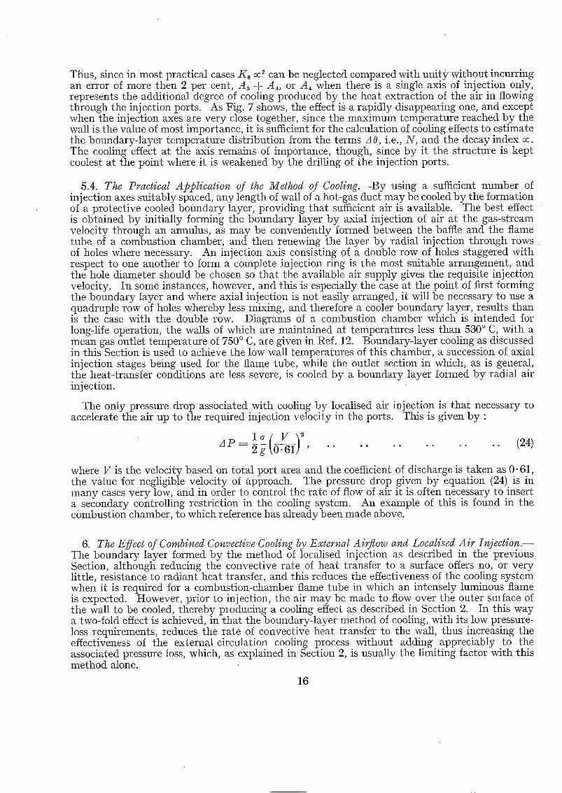
5.4. The Practical Application of the Method of Cooli~g.--By using a sufficient number of injection axes suitably spaced, any length of wall of a hot-gas duct may be cooled by the formation of a protective cooled boundary layer, providing that sufficient air is available. Tile best effect is obtained by initially forming the boundary layer by axial injection of air at the gas-stream velocity through an annulus, as may be conveniently formed between the baffle and the flame tube of a combustion chamber, and then renewing the layer by radial injection through rows of holes where necessary. An injection axis consisting of a double row of holes staggered with respect to one another to form a complete injection ring is the most suitable arrangement, and the hole diameter should be chosen so that the available air supply gives the requisite injection velocity. In some instances, however, and this is especially the case at the point of first forming the boundary layer and where axial injection is not easily arranged, it will be necessary to use a quadruple row of holes whereby less mixing, and therefore a cooler boundary layer, results than is the case with the double row. Diagrams of a combustion chamber which is intended for long-life operation, the walls of which are maintained at temperatures less than 530 ° C, with a mean gas outlet temperature of 750 ° C, are given in Ref. 12. Boundary-layer cooling as discussed in this Section is used to achieve the low wall temperatures of this chamber, a succession of axial injection stages being used for the flame tube, while the outlet section in which, as is general, the heat-transfer conditions are less severe, is cooled by a boundary layer formed by radial air injection.
The only pressure drop associated with cooling by localised air injection is tha t necessary to accelerate the air up to the required injection velocity in the ports. This is given by :
z l P _ 2 g ~ ' " . . . . . . . . . . . (24)
where V is the velocity based on total port area and the coefficient of discharge is taken as 0.61, the value for negligible velocity of approach. The pressure drop given by equation (24) is in many cases very low, and in order to control the rate of flow of air it is often necessary to insert a secondary controlling restriction in the cooling system. An example of this is found in the combustion chamber, to which reference has already been made above.
6. The Effect of Combined Convective Cooling by External Airflow and Loealised Air [email protected] The boundary layer formed by the method of localised injection as described in the previous Section, although reducing the convective rate of heat transfer to a surface offers no, or very little, resistance to radiant heat transfer, and this reduces the effectiveness of the cooling system when it is required for a combustion-chamber flame tube in which an intensely luminous flame is expected. However, prior to injection, the air may be made to flow over the outer smface of the wall to be cooled, thereby producing a cooling effect as described in Section 2. In this way a two-fold effect is achieved, in that the boundary-layer method of cooling, with its low pressure- loss requirements, reduces the rate of convective heat transfer to the wall, thus increasing the effectiveness of the external circulation cooling process without adding appreciably to the associated pressure loss, which, as explained in Section 2, is usually the limiting factor with this method alone.
16

6.1. Theory of Opera t ion . - -To examine mathematical ly the method of cooling, consider the rate of heat transfer to and from the wall to be cooled. When equilibrium conditions have been attained we have •
ho(0~ - - 04) = h ~ ( 0 ~ - 0~) + h , ( T . - 0 5 . . . . .
But according to equation (21), in the previous Section, 0L is given by •
T~-- 0L = A0 e-~L . . . . . . . . . .
. . . . . . (25)
. . . . . . (21)
where x is measured from the point of injection. If, in the arrangement under discussion, the air in the cooling passages and the boundary layer over the hot surface of the wall, flow in opposite directions, as is necessary for the best cooling effect, and x is measured from the point of entry of the air to the cooling passages, which are of length L, equation (21) becomes :
Tg - - OL = AO e ~I~-LI . . . . . . . . . . . . . . . . . (21b)
Substituting for 0r in equation (25) gives :
h4(O~ - - 0~) = h L ( T g - AO e °~(~-L' - 0~) + h~(T~ - - 0~) . . . . . . . (25a)
From this point the theory of the cooling process follows closely tha t developed for external convective cooling alone in Section 2. Substitution for 0~ in equation (25a) is made from equation (2a), i.e.,
d o ~ _ K ~ ( o ~ - - oo) . . . (2a) d X - - " " " " " ' " " ' " " "
The substitution gives
h4 dO~ _ Tg(hL + h,) - - hL A 0 e I'-LI~ hL dos h, dO4 Kl~ dx K I dx hL04 h,O~. K~ dx
Rearrangement of this
where
equation gives •
dO 4. -dx + K70~ = KTTg - - Ks AO e (~-LI*,
h, + hL K7 = h4 + h, + hLKI '
ha Ks = h4 + h, + hL K1.
. . (25b)
. . . . . . . . (25c)
Integrating this equation with the aid of the factor eK7" and inserting the end condition that 04 = T~ when x = 0, gives •
- ( K d°eF i A 0 K8 el~_L/~ + T~ - - T ~ e - K 7 * . . . . Tg--04 K T + o c KT+OC ] . (26)
A similar process with the case in which there is no radiant heat transfer, or in which it can be
AO K , ) K , + oc e-°~L e-Kg~' (27)
neglected, i.e., h, ----- 0, gives •
A 0 K, + (T~ -- T4 -- - - T g - - 0 4 = K , + oc e(x--L) o~
where K . - - K1/K~, i.e.,
h '~d - C ~ W ~ "
17 ( 7 4 6 1 4 ) B

Neither equation (26) nor (27) can be solved explicitly since it is necessary to know the air tempeiature at the point of injection, i.e., at x = L, in order to calculate the initial b o u n d a r y - layer temperature from the appropriate mixing factor N. But a value may be assumed to start with, and the coiresponding value of ~0 substituted into either equation (26) or (27). If the calculated value of the air temperature at x = L does not then agree with the assumed value the process must be repeated until agreement is obtained. Having thus derived the final equation needed to evaluate the air 'temperature, 0a, at any point in the cooling system, values of this may be substituted into equation (25a) and the wall temperature distribution calculated.
As is apparent from the foregoing theory of the cooling process, the method is very similar to tha t involving external airflow alone (as described in detail in Section 2). To estimate the associated pressure drop, the value given by equation (6) should be added to that given by equation (24), while if necessary to increase the rate of heat extraction from the air side of the system, secondary surfaces may be used in the manner described in Section 2.3. The only difference between the method of cooling described in this Section and that of Section 2 is tha t in this case the gas side of the wall is swept by the comparatively cool boundary layer instead of by the hot gases, an effect which is simply achieved by dividing the air passage into lengths to correspond with the injection axes, and drilling injection ports of the requisite area in the wall at the end of each section.
7. Conclusion.--A Comparison belween the Different Methods of Wall Cooling.--In this report several methods of cooling surfaces which are swept by hot gases have been considered, in all of which, since the principal application of the methods is to gas-tin-blue combustion systems, air is used as the coolant. Each of the methods has certain advantages and disadvantages which are of varying relative importance, depending upon the duties of the gas turbine for which the cooled combustion system is intended.
A comparison between the different methods o_f cooling which have been discussed is made in Fig. 11, which shows the results of some calculations undertaken to assess the cooling effects possible in a typical, but hypothetical, hot-gas duct, the walls of which were cooled by varying airflows used in each of the methods described.
I t is apparent from Fig. 11 tha t by far the most efficient and effective of these methods is sweat cooling, which uses the porous wall with its large area for heat extraction and which produces, in certain instances, the additional effect of a reduction in heat transfer to the cooled surface by virtue of a thickening of the laminar boundary layer, through which heat can pass by conduction alone. The uniform distiibution of coolant and cooling effect associated with sweat cooling make it, thermodynamically, the ideal method, since no cooling effect is wasted by maintaining one point of the surface at some excessively low temperature in order tha t a second shall not exceed its allowable maximum. This factor, coupled with the effect of the large internal surface area which makes resistance to heat flow on the air side negligible, maintains sweat cooling as still the most effective method even when the hot-gas flow conditions, as in the entry lengths associated with abrupt discontinuities in fow, are such that no appreciable reduction in the rate of heat transfer to the wall is caused by the injection of the cooling air.
Unfortunately full advantage of the merits of sweat cooling cannot yet be taken, because the porous metals commercially available all need cooling to temperatures which are, in engines • which include a high-efficiency heat exchanger, lower than those prevailing at entry to the
c o m b u s t i o n system. As was pointed out in Section 4, however, t h e advantages to be gained from the availability of a porous material having properties suitable for gas-turbine dncting warrant any metallurgical effort required in its development; because the need for such an effective and efficient means of wall cooling will become increasingly urgent as combustion- chamber outlet temperatures increase, and thus make less air available for wall coding.
Foi reasons similar to those given in explaining the effectiveness of sweat cooling, the louvred wall supplies the second most efficient method of those considered. It falls short of sweat cooling with no 'blanketing' effect only because it is not practicable to construct a louvred surface
18

containing as many air passages, and hence as large an internal surface, as is found in the t ruly po rous wall. The louvred combustion-chamber flame tube, as described by Lubbock in Ref. 5, is in effect the result of an at tempt to create artificially a porous wall.
The calculations on which Fig. 11 is based assumed that the mode of heat transfer from the hot gas to the surface to be cooled was by convection alone, and the performance curve of the louvred Wall given in this Figure is, a pa r t from tha t of the external airflow method alone, as described in Section 2, the only one which is not lowered by replacing part of the couvective by radiant heat transfer. This is because the louvred wall depends for no part of its calculated cooling effect upon a reduction in heat transfer by blanketing, and the effectiveness of the cooling method which still results makes the louwed wall particularly suitable for the flame tubes of
• large low-velocity combustion chambers in which the intensely luminous flames associated with the combustion of heavy fuel oils or coal are expected, and whelein radiant heat transfer far outweighs that resulting from convection. The main disadvantage associated with the louvred form of construction (its relatively great weight and bulk), may only be of secondary importance in suchcases, which are likely to be either marine or power-station gas-turbine applications, in which savings in weight and space can be sacrificed in the interests of reliabihty.
Each of the remaining three methods of wall cooling, results in non-uniform surface temperature distributions and therefore, since it is the highest temperature reached in a system which must be used to assess the cooling effect, they are necessarily less efficient than those which use either the porous or the louvred wall. Of the three methods, as would be expected, that described in Section 6, which is a combination of the other two, is the most effective and should be used whenever it is necessary to obtain the highest degree of cooling with a givenairflow and allowable pressure drop without resorting to either porous materials or the louvred form of construction. The remaining two means of wall cooling, those which involve either a controlled external flow of air, or localised boundary-layer injection, produce roughly equal cooling effects, the actual relative values depending upon the allowable pressure drops in the system. Both require the minimum of comphcation in constructional arrangements and are especially suited for moderate outlet temperature combustion systems in which there is a large mass flow of air in excess of that required to obtain efficient primary zone combustion.
Briefly, reviewing the available methods of wall coohng for gas-turbine combustion systems as described in this report, we have, firstly, sweat coohng, which with the development of a suitable porous material would become Lhe universal method. Secondly, there is the heavy and expensive louvred wall which should only be used as a last resort fo~ flame tubes subjected to the most ardous heat-transfer conditions in which reliability and length of life are of supreme importance. Thirdly, there is the less efficient but still effective cooling method which involves both external airflow and localised injection, which can be used to increase the working life of ordinary types of combustion system, while either of the remaining two methods, although not capable of high coohng effects, each possess the virtue of extreme simplicity. Finally, however, from a study of all or any of the cooling systems which have been described, one conclusion emerges which is almost obvious ; tha t is, tha t in any cooling problem, the associated difficulties, like the quant i ty of coolant required, increase with the size of the surface exposed to the hot gases, and therefore it should be the aim of the designer of any combustion system to keep the area of the walls to an absolute minimum.
8. Acknowledgments.--The author is indebted to Mr. W. A. Pennington who was responsible for some of the tests upon which Section 5 isbased, and to Mr. P. S. Lamb for assistance with the laborious calculations necessary for the analysis of the results of these tests.
19 74614) C

A, A1, A2, etc.
al, a2, hi, b~
B
c,,,
Cp
d
de
E
F
f G
g
H
h
h,
K1, Ks, etc.
L
Nu
A P
p, Q
Re
T
t
V
w~ X
YJ oc
NOTATION
,Constants of integration used in various equations, and defined appropriately in the text
Exponential indices obtained in the solution of various equations, and defined in the text
A constant
Area available for the conduction of heat in the metal of a wall
Specific heat at constant pressure
Diameter of a duct
Equivalent diameter as defined in the text
Emissivity
Surface area for heat transfer
Heat-transfer area per unit length
Mass velocity
Acceleration due to gravity (32.2)
Rate of heat flow
Coefficient of heat transfer
Equivalent coefficient of heat transfer due to radiation (see App. I)
Coefficients used to facilitate the solution of various equations and defined appropriately
Length of a flow passage
Nusselt number (hde/Z)
Pressure drop
Fin pitching
Cooling-air mass flow per unit cooled-surface area
Reynolds number (deG/tzg)
A known and constant temperature
Metal thickness
Velocity
Cooling-air mass flow
Distance from an arbitrary origin
Fin height
Exponential index used as a measure of the rate of decay of a boundary layer
20
(dimensionless)
(It ~)
(C.H.U./ lb °C) (It) (It) ~dimensionless)
(re) (fP/ft) (lb/sec I t ~)
(ff/sec ')
(C.H.U./sec)
(C.H.U./ft ~ sec °C)
(C.H.U./ft ~ sec °C)
(It) (dimensionless)
(lb/fP)
(It)
(ib/sec ft ~)
(dimensionless) (oc)
(It) (if/see)
(lb/sec)
(it) (it) ( i t-,)

Suffix
~1~ ~2
Y
.0
0
AO
t7
# .
N O T A T I O N - - c o n t l n u e d
Constants of integration used in the solution of equation (A.9a)
Coefficient of permeability of a porous wall
Boundary-layer thickness
A temperature at any point in a system
The temperature difference between tile boundary as formed initially by localised air injection, and the main gas stream
Specific weight
Coefficient of viscosity
Coefficient of thermal c0nducfivity
A parameter used to define the efficiency of secondary surfaces, and defined in the text
Cooling efficiency, defined in the text
g
vd
L
Refers to the hot gas stream
Refers to the cooling air
Refers to the wall-being cooled
Refers to the boundary layer certain of the cooling methods
associated with
(in?)
(ft) (oc) (oc)
(lb/ft ~)
(lb-sec/ft 2)
(C.H.U./ft see °C)
(dimensionless)
(dimensionless)
(74614) C2

No. Author
1. F . J . Bayley . .
9.. F . J . Bayley . . . .
3. A .G . Smith . . . . . .
4. K . A . Gardner . . . .
5. I . Lubbock . . . . . .
6. P. Duwez and H. R. Wheeler
7. D . W . Rannie . . . .
8. P. Grootenhuis and N. P. W. Moore
9. P. Grootenhuis and N. P. W. Moore
10. M. Muskat . . . . . .
11. H . B . Rose . . . . . .
12. H. Constant, P. Lloyd and R. P. Probert
REFERENCES
Title, etc.
The cooling of a hot-gas duct by injection of air at the wall. N.G.T.E. Report R.62. A.R.C. 13,339. January, 1950.
Notes on wall cooling. N.G.T.E. Memo. M.90. A.R.C. 13,340. July, 1950.
Heat flow in the gas turbine. Proc. Inst.Mech. Eng. Vo1.159. W.E.P.41. 1948.
The efficiency of extended surfaces. Trans. A.S.M.E. p.621. November, 1945.
Combustion problems in the gas turbine. Trans. N.E.C.I.E.S. Vol. 67. p. 131. 1951.
Experimental s tudy of cooling by injection of a fluid through a porous material. J.Ae.Sci. Vol. 15. No. 9. 1948.
A simplified theory of porous wall cooling. Paper presented at Los Angeles Fluid Mech. Inst. June, 1948. (Quoted in Ref. 8.)
Some observations on the mechanism of sweat cooling. Proc. VII th Inter- national Congress of Applied Mechanics. 1948.
Sweat cooling. The Engineer. p. 230. February, 1950.
The Flow of Homogeneous Fluids Through Porous Media. McGraw-Hill Book Co. 1937.
Fluid flow through beds of granular materials. Proc: Inst. Mech. Eng. Vol. 153. p. 141. 1945.
Two papers in a symposium on internal combustion turbines. Proc. Inst. Mech. Eng. Vol. 163. ,W.E.P. 60. 1950.
22

APPENDIX I
A Note upon Heat Transfer in Combustion-Chamber Flame Tubes
I t is rarely the case that the ideal conditions of developed flow to which the standard convection heat-transfer equations strictly apply are found in practice, although often such equations, of which equation (4) (Section 2.2), is the most commonly used, may be applied without serious error. But in combustion chambers the conditions are normally so far removed from the ideal that large inaccuracies in the estimates of heat-transfer rates will be incurred unless corrections are applied to the standard formulae.
The corrections must, of necessity, be empirical and the only really accurate way of obtaining values for these is to make heat-transfer tests under conditions of flow exactly similar to those which will prevail in practice. This is, in fact, the method of obtaining heat-transfer coefficients in flame tubes which is adopted by manufacturers who make many combustion chambers of similar design, but it is not practicable when one or two units only of each type are to be made, as for large industrial gas-turbine sets or for experimental purposes, and in suctl cases it is necessary to assess the required correction from previous experience obtained under as near similar conditions as is possible.
For most combustion-chamber flame tubes it has been found that multiplying the heat-transfer coefficient given by equation (4) by a factor of from 2.0 to 2.5 gives a value for the convection heat-transfer coefficient between the hot gases and the wall which is sufficiently accurate for most wail-cooling calculations. This tactor may be compared with the value measured when the N.G.T.E. porous duct was used as a flame tube. The baffle used to stabilise the flame in this experiment was of typical design, and provided a degree of swirl which is usual for most flame stabilising purposes. Lubbock in Ref. 5 recommends that equation (4) be used, basing the Reynolds number on the swirl velocity instead of upon the mean axial velocity as is usual. This gives a more general correction, provided tha t the swirl velocity is known.
In addition to heat transfer between the hot gases and the flame-tube wail by convection, there is often the effect o f radiation to be taken into account. In most combustion chambers burning a distillate fuel such as kerosene, radiant heat transfer is less than that taking place by convection, and can often be neglected, but when the heaviest of residual fuels is being burned the reverse is often true.
Now the net radiant-heat exchange between two black bodies at temperatures respectively Tg and T~ is given by
H = Fg 2"8 × 10-12(Tg 4 - - T~ 4) . . . . . . . . . . . (A.1)
Now if the two radiating media are respectively a gas and the walls which bound it, the equation becomes :
H = F~ 2 ' . 8 × 10 -I~ Ew'(E, Tg~-- AeT~4), . . . . . . . . (A.2)
where A s is the absorptivity of the gas for radiation from a surface at temperature T~, and E~' is a corrected emissivity for the surface, usually taken as half-way between its true value and unity, which allows for the additional opportunity for absorption by the gas of the radiation reflected from the walls. Although there are many data available about the emissivity and absorptivity of gases, both luminous and non-luminous, at pressures substantially atmospheric, there is little information available about the Values at higher pressures such as are found in gas-turbine combustion chambers, although it is known that radiant-heat interchange increases with pressure. In view, therefore, of the uncertainty of the values of the gas emissivity and
23

absorptivity under operating conditions, coupled with the difficulty of accurately assessing the gas (or flame) temperatures, it is not believed tha t the use of the complicated equation (1.2) is warranted, and a simpler a!ternative can be used with equal confidence •
H = Fg 2.8 × 10 -12 EM(T~ ~ - T~ ~) . . . . . . . . . (1.3)
in which E M is an equivalent emissivity for the gases and walls. Values of this are not known with any accuracy, but it is recommended that to estimate the order of the rate of radiant heat transfer, EM is taken as 0 - i for distillate fuels, such as gas oil, burning under luminous flame conditions and radiating to normal oxydised metal surfaces having an emissivity of about 0" 8, as 0-2 for the heavier industrial fuel oils such as are burned under boilers, and as 0.3 for the heaviest residual oils and pulverised coal, which are, however, not yet commercially used in gas turbines.
In order to convert equation (A.2)•into a more convenient form, use may be made of an equivalent heat-transfer coefficient, h,, which is based upon the temperature difference between the wall and the gas (or flame), and which is given by
h, = 2"8 × 10 -~2 EM [ T~ -- T~4) (A.4) \ T~-- ~-~ . . . . . . . . . . .
The use of this equation requires a knowledge of T~, but since the effect of this is much less critical in practical cases than that of Tg, an initial estimate of the wall temperature which is not too greatly in error will enable hr-to be calculated, and it m a y then be combined with h v the overall convective heat-transfer coefficient, unless the cooling system which is being used for the wall in question involves the use of a blanketing laye r of air, which offers no resistance to radiaii: t heat flow.
r
24

APPENDIX II
T h e Relation between the Overall Heat-Transfer Coefficient between a Gas and a Wall and the Reynolds-Analogy Convection Coefficient
Suppose hc is the coefficient of heat transfer which takes place by convection alone, with no laminar conduction effect, between a turbulent gas stream at temperature T v and a heat sink, as is assumed in the Reynolds analogy between heat transfer and fluid friction. Suppose that t h e turbulent gas stream in question is separated from a surface at a temperature 0~, by a laminae boundary layer of thickness 8, which is of temperature 0L at the surface furthest from the wall. Then the heat flow by conduction through the boundary layer is equal to that transferred to it by turbulent convection from the gas stream, i.e.,
aL 0L - % _ h ~ ( T , - - 0 J
Therefore O k - 2LO, + Oh, Tg (A.5) -- ~L + 0h~ . . . . . . . . . . . . .
Also the overall rate of heat transfer between the gas stream and the wall, H', is given by •
H ' = h e ( T e - - 0~) .
Therefore, since this heat flow is equal to t h a t b y convection to the boundary layer, we have •
h ~ ( T g - o j = h e ( T e - - 0 5 . :
'Substitute for 0k from equation (A.5) and we get
hcTg ~hcT-~ h~ = h e ( T , - - O~)-
h~T,~L -- ,~LO~oho ---- he(T e " O~)(,~L + ~h,) , whence
o r
Thus if (8 hc)/2 < 1, we have
andi f (Oh~)/2 ~/. 1, we have
hg-- h6
l q - ~
h , - ' - h o , . . . .
. . (A.6)
. . ( A . 6 a )
. . A.6b)
25

A P P E N D I X I I I
A General Solution for the Temperature Distribution in the Ideal Boundary Layer formed by Localised Air Injection (see Section 6)
Consider the boundary layer as a complete and separate annulus of gas moving uniformly downstream from the point of injectionl The balance of heat transferred to and from an elementary length of it under steady conditions is thus :
dOt C~W~ - d - ~ x = h~rHd~ ~x(T, -- T~) -- h y d ~x(OL -- 0~) . . . . . (A.7)
hg~ is the equivalent heat-transfer coefficient between the gas stream and the boundary layer, and dL is the internal diameter of the lat ter , the case of the cylindrical duct being considered.
Consider now the balance between the heat conducted axially into and out of the wall covered by the elementary length ot the boundary layer, and that convected to i t :
dOg,x) doll We have, therefore,
OL = 0~, - - ~,t d20~ hL dx ~ " . . . . . . . . . . . . ~ (A.8)
Substitution in equation (A.7) for 0L from equation (A.8) and rearrangement of the terms gives :
CpW f i J d~O. FhgL d20w d2°~°l + CpW,~ dO,, hgzHdL(Tg- 0~,) : 0 (A.9) hL dx 8 17~t khL dL d-Z + d dx2j dx
For convenience, we make the following substitutions •
a~t hL -- K~ (as in Section 5.3 (iii))
hgLIIdz ---- Klo
Then "
- - CpW~K6 d%~ dx ~
hLIId : K n .
- - - - K s ( K 1 0 ~- Kn) -d~ + d20w CpW~-~ dOw - - - - K ~ 0 ( T g - 0~) = 0 . . . (A.9a)
The solution of this equation, which gives the wall temperature at any point x ill the system is :
0w = Tg + / h e b- + / 3 ~ e~2. + f13 e ~3, . . . . . . . . . . . • (A. 10)
where ~1, /~, /~3, are constants of integration and b ----- bl, b2, b3 are the roots of the auxiliary equation,
-- CpWoK~b 3 -- K6(Klo -/K~1)b ~ + CpW, b + K~o = 0 . . . . . (A.11)
Thisequat ion (A.11) is a cubic in b and therefore is not capable of direct and general solution. If K0, KI0 and/£11 could be calculated, a graphical solution or some method of successive approxi- mations might be used to obtain b~, b~ and b3, but the complexities Of the heat-transfer processes
26

involved make it impossible to estimate the rate of j heat exchange between the main gas stream and the boundary layer, and hence K10. Thus to solve completely the equation associated with boundary4ayer cooling, it is necessary to make an assumption such as that made in the less rigorous theory of Section 6. The solution given by equation (23) and obtained by assuming that the boundary-layer temperature distribution follows the simple exponential equation (equation (21)), comp.ares with the general solution given by equation (A.10), and is identical if:
bl = 1 / v ' K ~ [~1 = - - A 3
- - b2 = - - 1 / V K 6 #~ - - - - - A ~
A O
b3 ---- - - oc fi3 - - 1 - - K 6 o c 2"
27

GO
I.D
0.~
O-C
0-4
0,2
X X
\
(~ : TANH LLF
0 Io0 2"0 3.O ,~'0
w b
¢ = AVERAGE TEMPERATURE DIFFERENCE OVER FIN
6O
= COEFFICIENT OF HEAT TRANSFER
/~.~-~ = THERMAL CONDUCTIVITY OF FIN
1o.
5,0
AVERAP~E TEMPERATURE OWFERENEE AT BASE
= FIN HEIGHT " .,,-.., FT.
,,~ C,H,U, / FT.~SEr_°C
,-, E.H,U,/FT. SEC,°C
= HALF BASE THICKNESS OF FIN ~ . FT.
FIG. 1. E f f i c i ency of s e c o n d a r y sur faces .
8AS TEMPERATURE =750~C; COOLING AIR TEMPERATURE * 3SO ~C.
F i N DIMENSIONS:- LENGTH 10 -1 FT.~ THsCKNESS Io-2F'T.~ GAP 4-X l0 -~IFT,
a(J I
:E ,.i I- J /
:E
x < 2
SE~
50O
450
FIG. 2 0 .
" EFFECT OF A
DTAiNLESB " - - ~ L VARYING AiR FLOW
a 4 Q b "~
AIR FLOW PER GAP~ L B / S E C .
470
440
4 3 0
o,J (
w ~ 4f0
~go
W A L ~ / t
370 / / / /
350 ~ / / ~- B 8 " 10 -#
DISTANCE ALONG FIN-FT
"" " F|8. ~ b
'~t'~ ,HE. TEMPERATURE
oVP ~' SYSTEM WITH A
, / / CONSTANT AIR FLOW
FIGS. 2 a a n d 2 b . T h e cooling effect i n a l o u v r e d wall .

f . . AiR INLET
5HIELBED THERMOCOt]PLES
5"rkTIC PRESSURE POINT
" SECt'ION "
\, G~,~ FLOW FROM
T/C JOINT
METHO~ OF INSTALL|NG T H E R M 0 C 0 U P L E S •
L A G G t N ~ _
HkCK CHAMBER 'B I UPS"I'RF..P~M
_ _ ~ I K ~ \\ \\
-'-----P/kCKED EXPANSION GLAND
FIG. 3. Test rig for porous-walled duct.

, SYMSOL, ~AS TEMP, (9 300 °~ • 350 °k [] 400 °
I'0 - - m 4.50 °C + SO0 °~ a 900 °~ v . 700 °[:
0'4
" ' 0.~
® , - "
o I ~ 3 4 5 MASS FLOW ~ATI0 ~/~
7 8
lq'I~. 4. Observed cooling effect compared With the theory given by Rannie (Ref. 7).
30

02 ILl tO
Z
ILl
Z
400
300
~00
100
0
¢00 +
30C
iOC
I00
FIG. 5.
R E K G RESLIL'I"S.
Re. = 9 . 6 x I0 4"
~'~ x I0 4
5.5 x 16 +
~ '5 x I0 ¢ 4 ~ ,4,,
_..." ,o,
--o 1.6 x tO s
¢
N.q.T.E. R~SUUT£ i
4- 8 8 ..t:OOLING I AIR FLOW/.StJ~FAo,,E AI~A ~AS FI..OW/~.KOSS - SECTIONAL. A~'EA.
I.?. x 1o 5 I
I0
Effect of cooling-air flow on the rate of heat transfer to a porous wall.
1.0
>. t . )
Ld ¢ J
tL .6 h . t , i
1,9 Z .4 . . I 0 o o
-p.
G
E Lt.I
8
/
/ /
I 2 3 + 5
F IG .60
N.6.T.E. RESULT5
'YMSOL. T$ Re i O 3 0 0 BxlO' • 3 5 0 2"2 + 4,00 1"7 B 4 5 0 J'6
5OO 1-3 600 1.2
v 700 I- I
6 7 / xl &so"
I.O
IDuwEz ~ WHE~ER'~ULTS
~' 4 6 8 IO [~ 14 | 6 . xlO "+"
FIGS. 6a and 6b. An improved correlation for the cooling effects in porous-walled ducts.

30Q
I•'?.OC m, "- ' l
I-
B_
h i
100
I . Z
9 P
I I t OUNDAI~Y LAYEI~ TEMPEI~ATUI~E
/
EMPEI~ATU~E
<
CIAS .'rE: MPEI~ATIJ R E ~
- - 12
(~ POIN"r.~ CHOSEN TO CALCULATE TNE' C..OEFF~
B ¢
INCHES FROM INJECTION AXIS
FIG. 7. Calculated wall and boundary-layer temperature-distribution curves.
82

e.¢
Z !
Z
o L .
IJ ILl
Li
I
0
I
0
3
0
FIG. 8.
J
. . . . . . ~ ;"
r
0
f
®
o j /
/ / / / / . ~ ~ 0
°-'oER IC5 F
, / 0
. . / ®
J il
~FI~IES b
.MCAN AXIAL, VCI~oO.rrY OF C~A% IRADIAL INJ~CTION VCLOC-ITY 0r'AIR
,~CRiC -°- A_
5 G
The effect of injection velocity ratio on the initial degree of mixing in the boundary layer.
T i:-. !
~f X lai
X
hi
' i I,,-- li.
X o
0.1
( N + ' ) W !
o-P.
" ~ ' L B / $ E C .
O ~ O-dl.
o<, o o /
/
0 O'P. 0"4- 0 .6 0 . 8 I.O ,X lO 6
~ FT. SEC
(N,,- I~ Wa., L~.
FIGS. 9 and 10. The effect of gas-stream Reynolds number and mass of the boundary layer upon its
rate of decay.

80
(; so >. (.J 7 hi CJ b- b e Z .-I g i.j
2C
J f
I
E
;3
+
I'0 2.0 AIR FLOW/UNIT COOLED SURFACE
CIAS FLOW/UNIT X-SECTIONAL AREA -
ct G
LOrALISED INJECTION
EXTERNAL AIR CIRCULATION
COMBINATION OF I AND 2
(~P- 3.6 LB/FT. ~)
(~p, G.o LE/FT. ~)
(,,,~ ~- ~.o L~/r , i 2)
LOUVRED CONSTRUCTION
S POROUS WALL
3,OXlO -~
COOLIN6 EFFICIENCY -- T~" BwMA x
T 9 -To.
FIG. 11. A comparison between the different methods of wall cooling.
34 (74614) Wt. 53]2293 K.7 7/59 Hw. PRINTED IN GREAT BRITAIN

R. & M. No. 31
Publications of the Aeronautical Research Council
A N N U A L T E C H N I C A L REPORTS OF THE AERONAUTICA L RESEARCH COUNCIL (BOUND VOLUMES)
1939 Vol. I. Aerodynamics General, Performance, Airscrews, Engines. 5os. (52s.). Vol. II. Stability and Control, Flutter and Vibration, Instruments, Structures, Seaplanes, etc.
63s. (65s.)
194o Aero and Hydrodynamics, Aerofoils, Airserews, Engines, Flutter, Icing, Stability and Control, Structures, and a miscellaneous section. 5os. (52s.)
I941 Aero and Hydrodynamics, Aerofoils, Airscrews, Engines, Flutter, Stability and Control, Structures. 63s. (65s.)
1942 Vol. I. Aero and Hydrodynamics, Aerofoils, Airserews, Engines. 75s. (77s.) Vol. Ii. Noise, Parachutes, Stability and Control, Structures, Vibration, Wind Tunnels.
47s. 6d. (49 s. 6d.)
I943 Vol. I. Aerodynamics, Aerofoils, Airserews. 8os. (82s.) Vol. II. Engines, Flutter, Materials, Parachutes, Performance, Stability and Control, Structures.
9os. (92s, 9d.) 1944 Vol. I. Aero and Hydrodynamics, Aerofoils, Aircraft, Airscrews, Controls. 84 s. (86s. 6d.)
Vol. II. Flutter and Vibration, Materials, Miscellaneous, Navigation, Parachutes, Performance, Plates and Panels, Stability, Structures, Test Equipment, Wind Tunnels. 84s. (86s. 6d.)
t945 Vol. I. Aero and Hydrodynamics, Aerofoils. I3OS. (132s. 9d.) Vol. II. Aircraft, Airserews, Controls. 13os. (i3zs. 9d.) Vol. III. Flutter and Vibration, Instruments, Miscellaneous, Parachutes, Plates and Panels,
Propulsion. 13os. (*32s. 6d.) Vol. IV. Stability, Structures, Wind Tunnels, Wind Tunnel Technique. 13os. (132s. 6d.)
Annual Reports of the Aeronautical Research Council-- I937 2s. (2s. 2d.) x938 IS. 6d. (IS. 8d.) I939-48 3s. (3s. 5d.)
Index to all Reports and Memoranda published in the Annual Technical Reports, and separately--
April, 195o - R. & M. 2600 2s. 6d. (2s. Iod.)
Author lndex to all Reports and Memoranda of the Aeronautical Research Council--
I9O9--January, 1954 R. & M. No. 2570 ISS. (ISS. 8d.)
Indexes to the Technical Reports of the Aeronautical Research Council--
December I, I936--June 3o, 1939 R. & M. No. I85O IS. 3d. (is. 5d.) July 1, I939--June 3 o, 1945 R. & M. No. 195o IS. (is. 2d.) July 1, I945--June 3o, 1946 R. & M. No. 2o5o IS. (IS. 2d.) July I, I9¢6--December 3I, I946 R. & M. No. 215o IS. 3d. (IS. 5d.) January I, I947--June 30, 1947 R. & M. No. 225o is. 3d. (is. 5d.)
Published Reports and Memoranda of the Aeronautical Research Council--
Between Nos. 2251-2349 R. & M. No. 235o IX. 9 d. (IS. IId.) Between Nos. 2351-2449 R. & M. No. 245 ° 2s. (2s. 2d.) Between Nos. 2451-2549 R. & M. No. 255 ° 2s. 6d. (2s. Iod.) Between Nos. 2551-2649 R. & M. No. 2650 2s. 6d. (2s. rod.) Between Nos. 2651-2749 R. & M. No. 2750 2s. 6d. (2s. Iod.)
Prices in ~rackets include postage
H E R MAJESTY'S S T A T I O N E R Y OFFICE York House, Kingsway, London W.C.z ; 423 Oxford Street, London W.I ~ r3a Castle Street, Edinburgh 2; 39 King Street, Manchester z ~ 2 Edmund Street, Birmingham 3 ; 1°9 St. Mary Street, Cardiffl Tower Lane, Bristol t
80 Chichester Street, Belfast, or tl2rough any bookseller.
S.C. Code No. 23-311o
R. & M. No. 31