final report - robovette - machine intelligence lab robovette eel 5666 – intelligent machines...
TRANSCRIPT
University of Florida December 8, 2009 A. Antonio Arroyo, PhD Department of ECE EEL 5666-Intelligent Machines Design Lab Eric M. Schwartz, PhD
RoboVette
Christian Davis
TAs: Mike Pridgen Thomas Vermeer
2
RoboVette
EEL 5666 – Intelligent Machines Design Lab Christian Davis, Electrical Engineering, University of Florida
Abstract – The robot, RoboVette, is an autonomous police car that enforces the speed limit by pulling over vehicles that have been caught speeding. RoboVette accomplishes this by waiting on the side of “the road” and continuously clocking the speed of oncoming vehicles. When a speeder is detected, RoboVette pulls out from its hiding spot and commences to pursue the speed offender until the vehicle is pulled over. The brain of the robot is an ATxmega128A1 microcontroller used to control a pair of motors and to communicate with a variety of sensors necessary for speed detection and pursuit. Infrared (IR) range-finders are used to detect speed while remote control IR transmitters and receivers are used to track the speeding vehicle once it has been detected. Ultrasonic range-finders are also used to avoid certain obstacles while moving as well as to determine the distance to the speeding vehicle that is being chased. Using the data acquired from all these sensors, RoboVette is able to detect and pursue traffic offenders who do not obey the speed limit.
TABLE OF CONTENTS
I. INTRODUCTION………………………………...…………………………....2 II. INTEGRATED SYSTEM…………..………………………………………….2
III. MOBILE PLATFORM.……………....………………………………………..3 IV. ACTUATION………………..………………………………………………….4 V. SENSORS……....………………………………………………………….…....4
VI. BEHAVIORS…………………………………………………………………...6 VII. EXPERIMENTAL RESULTS AND CONLUSION……….………………...7
VIII. REFERENCES………………………………………………………....………7 IX. APPENDIX A (SOFTWARE)..………………………………………………..8
I. INTRODUCTION
oboVette is an autonomous robot design for the Intelligent Machines Design Laboratory (IMDL) at the University of Florida. The robot’s objective is to
detect the speed of a passing vehicle and chase it if it has exceeded a predetermined speed limit. Robovette will be able to track and follow the vehicle and continue to follow it until the vehicle has been stopped and pulled over. To accomplish this, RoboVette will have to use a variety of 4 different sensors as required by IMDL, with one sensor being a special sensor. The sensors used along with other components utilized will be explained further in the Integrated System and the Sensors sections of this report.
The robot performs its tasks with the use of an Atmel ATxmega128A1 microcontroller, DC motor, motor controller, servo, and a combination of several sensors. The two major tasks of the design are speed detection and vehicle tracking. Vehicle tracking is the most important task of the two since
the main purpose of the robot design revolves around being able to follow the speeding car. Tracking is also the most intricate part of the design since it uses a custom-made array of remote IR receivers and is considered the special sensor of the design. These receivers are placed in a certain configuration to allow the speeding car to be kept straight ahead and to determine which direction the robot should turn in order to keep the speeding car straight ahead. Apart from the IR range-finders used for speed detection, a third set of sensors, ultrasonic range-finders, are used mostly to keep RoboVette from colliding into the speeding vehicle and to determine if the speeding vehicle has stopped.
This report begins by giving a brief organizational description of the system and follows with a description of the robot’s mobile platform and actuation. An overview of the sensors used and the behaviors of the design will also be given.
II. INTEGRATED SYSTEM
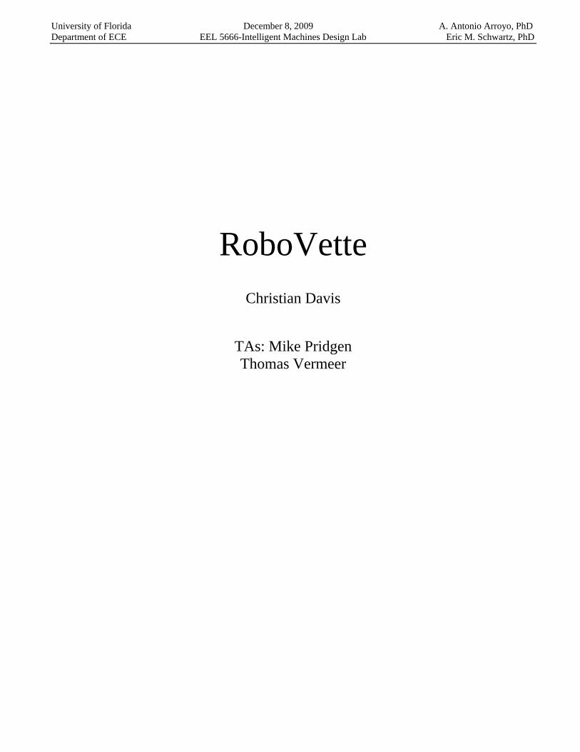
The structure of RoboVette’s integrated system is made up of the components shown in Fig. 1. The structure includes the required 3 sensors and the other components required and employed in the design. A short description and purpose of each component is listed below:
ATxmega128A1 PVR board– The brains of the robot.
This is the central processing unit where all code
R
Fig. 1. This is the integrated system layout for RoboVette.
3
executes and peripherals are interfaced. The board includes connections for A/D ports, PWM ports, power, I/O ports, and other peripherals.
LCD – Used as a debug screen as well as a status indicator for several robot activities.
Ultrasonic range-finders – Allow the robot to detect all obstacles in front of it and avoid colliding with the chase vehicle as well as help detect when the vehicle has stopped.
Infrared range-finders – Placed as a pair and used to measure the speed of a passing vehicle. Time is measured from the moment the first one detects an object to the moment the second one detects an object. This time is then used to calculate the speed.
Remote control infrared emitter – The emitter is placed in the rear of the chase vehicle and is used to track it while in pursuit. All cars in the RoboVette world emit remote IR light from the rear.
Remote control infrared receiver array – An array of remote control IR receivers is placed in the front of the robot and used to determine where the chase vehicle is at during pursuit. Three are positioned at different angles and have a certain degree of vision in front of them. The direction of the robot’s steering depends on which of the receivers see the IR light. This array of sensors counts as the special sensor requirement for the robot.
Servo – A servo is used to control the robot’s front steering.
Motor – The DC motor is used to spin the rear wheels forward and backwards for motion.
Motor controller – A motor controller is necessary to be able to power and control the speed and direction of the motor. It allows the processor to change the polarity of the power applied to the motor and use a PWM signal to control the speed.
Push button (not shown in diagram) – The push button will be used to signal the robot to begin its operation after it has been powered on. This will help avoid any false starts while powering on the robot.
III. MOBILE PLATFORM
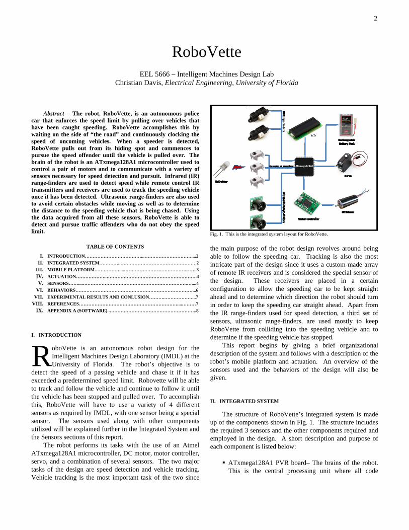
The robot’s mobile platform is basically that of a plastic 4-wheeled car chassis and body with rear-wheel drive and front-wheel steering. The platform for this design is a modified and gutted-out Jada brand 1/10th scale radio controlled Corvette car shown in Fig. 2. Several parts from the car were removed including the original control circuit board and the forward motor used for steering control. The only original components of the toy that have been recycled are the vehicle chassis/body including wheels and suspension/steering assembly, the battery harness, and most importantly the rear wheel motor. A PVR development board with an ATxmega128A1 was installed to replace the original
control circuit board and the front steering motor was replaced by a servo. The vehicle sensors and LCD screen are installed throughout the chassis and body. The mobile platform or car transports and operates all sensors
The front steering is based on the Ackerman Steering concept to prevent slippage while turning. The forward and backward motion comes from the rear-wheel drive powered through a small differential to turn both wheels. To mount the parts and sensors, many holes had to be cut into the car’s body. This required many hours of drilling, cutting, and measuring. To install the steering servo, a piece of the car chassis was cut out to allow the servo to be tied down and use the original steering linkage of the RC car. The rest of the mobile platform was basically already made since an actual RC car was chosen as a platform.
In order to easily work on the robot and debug any problems, certain features were added to the design. The first addition deals with the JTAG programming of the microprocessor on the robot’s development board. In order to avoid removing the body of the mobile platform from the chassis every time the microprocessor is programmed, the JTAG was duplicated and extended to a header port on the underside of the chassis. The wiring harnesses for the attached sensors on the body were also carefully passed through and affixed so that when the body does need to be removed, it can do so without much effort and without disrupting the sensor attachments.
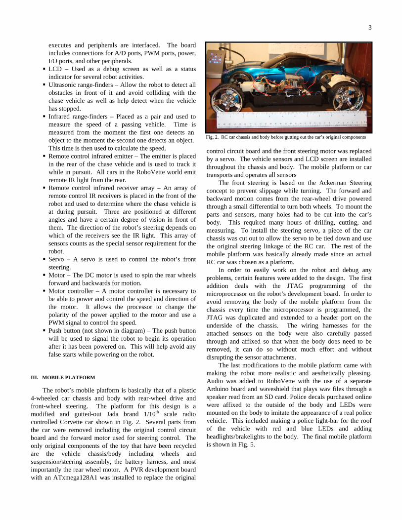
The last modifications to the mobile platform came with making the robot more realistic and aesthetically pleasing. Audio was added to RoboVette with the use of a separate Arduino board and waveshield that plays wav files through a speaker read from an SD card. Police decals purchased online were affixed to the outside of the body and LEDs were mounted on the body to imitate the appearance of a real police vehicle. This included making a police light-bar for the roof of the vehicle with red and blue LEDs and adding headlights/brakelights to the body. The final mobile platform is shown in Fig. 5.
Fig. 2. RC car chassis and body before gutting out the car’s original components
4
Fig. 4. Shown is the contr-oller used for actuation.
Fig. 3. Shown is the servo used for steering.
IV. ACTUATION
The actuation for RoboVette consists solely of a servo for front-wheel steering and a DC motor for rear-wheel drive to move the robot forward and backwards. A motor controller is used to power the DC motor and allow the microcontroller to control the speed and direction of the motor more accurately and efficiently with a PWM signal. A
PWM signal is also used by the servo. Varying the duty cycle of the PWM signals allows the microcontroller to vary both the speed of the motor and the position of the servo for steering while still providing a full voltage to either component. This is important in controlling the speed of the robot and the degree to which it turns.
The servo and DC motor in this design were chosen based on cost, application, and ease of use. The servo selected for front-wheel steering is the HS-322HD from Hitec (shown in Fig. 3). This servo provides a maximum torque of 51 oz-in with a full 90° range at a relatively low price. Its size was also desirable and came with an assortment of different gears and plastic arms. Like most servos, the position of the gear depends on the PWM signal sent from the microprocessor. After installing the HS-322HS in the robot, much time was spent figuring out which PWM value corresponded to full right, full left, center, and other variations in the wheels of the front steering assembly.
The DC motor used was not purchased but recycled from the RC car that was purchased. The motor meets the speed requirements of the design and using the original motor is also more cost-efficient than
purchasing a different one. The motor is nameless and provides no specifications; however, it has been measured to consume a peak current of about 1.8A when powered at full speed. The dual channel 1A motor controller with the Pololu TB6612FNG motor driver (shown in Fig. 4) was purchased from Sparkfun.com to regulate the speed and direction of the motor during operation. This component allows the use of two microcontroller I/O pins to change the polarity of the voltage applied to the motor (to go forwards or reverse) and a PWM signal to regulate the speed of the motor. By combining the two 1A channels of the controller in parallel, a single 2A channel was created to control the motor. During its operation, the robot predominantly uses the DC motor at full speed except in the situation where it is still chasing the vehicle and senses that the vehicle is very close in front of it. At this point it reduces the speed of the motor by changing the value of the PWM signal at the controller. All actuation provided by the DC motor, motor controller, and servo is crucial in successfully performing the robot’s functions.
V. SENSORS
Robovette uses 4 different sensors to perform its functions; Ultrasonic range-finders, remote IR receivers/emitter, IR range-finders, and a push button. These sensors are described further in this section.
A. Ultrasonic Range-Finders
Ultrasonic range-finders are used in RoboVette to detect
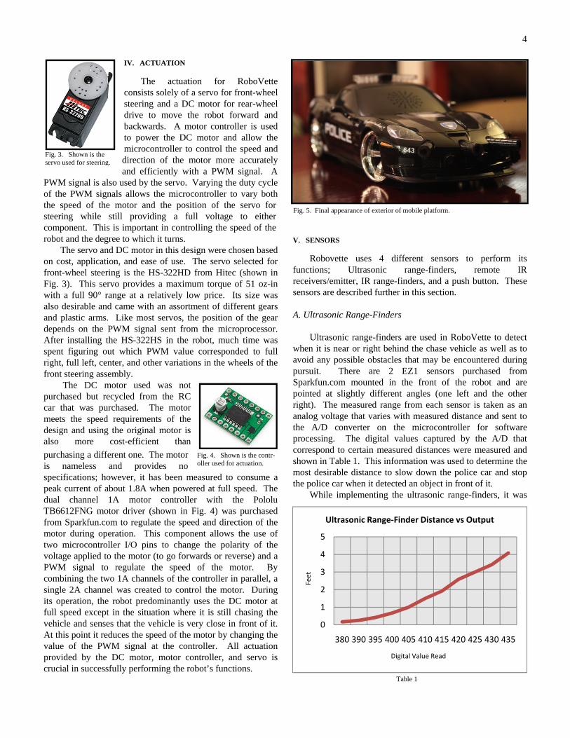
when it is near or right behind the chase vehicle as well as to avoid any possible obstacles that may be encountered during pursuit. There are 2 EZ1 sensors purchased from Sparkfun.com mounted in the front of the robot and are pointed at slightly different angles (one left and the other right). The measured range from each sensor is taken as an analog voltage that varies with measured distance and sent to the A/D converter on the microcontroller for software processing. The digital values captured by the A/D that correspond to certain measured distances were measured and shown in Table 1. This information was used to determine the most desirable distance to slow down the police car and stop the police car when it detected an object in front of it.
While implementing the ultrasonic range-finders, it was
Table 1
Fig. 5. Final appearance of exterior of mobile platform.
0
1
2
3
4
5
380 390 395 400 405 410 415 420 425 430 435
Feet
Digital Value Read
Ultrasonic Range‐Finder Distance vs Output
5
noticed that sensor outputs often contained a good amount of noise. This was most apparent when the sensors measured no obstacles in their way. To fix this problem, 22uF capacitors were placed at the output of each to filter out the noise observed. The response time of each sensor is now slower but the noise issue was mostly resolved. B. Infrared Range-Finders
The portion of the robot design dealing with measuring
the speed of the passing vehicle is solely based on the pair of IR range-finders mounted on the robot body. There are 2 Sharp 2Y0A21 IR range-finders purchased from Digi-Key.com. One is placed on the front left fender and the other is placed on the rear left quarter panel of the robot body. When set to detect speed, both sensors continuously measure the distance of any obstacles directly in front of them. When an object (in this case the speeding vehicle) crosses in front of the first sensor (the rear one) within a certain distance, a flag
Power On
Speed Detection
Detect Speed?
Y
N
IR Sensor 1 Detected Object?
N
IR Sensor 2 Detected Object?
Y
N
Y
Timer + 1
N Exceeded Speed Limit?
Pursuit-IDLE-
Y
Remote IR Detected?
N
Obstacle/Car Detected?
N
Move ForwardRemote IR Detected?
Y
Search
Remote IR Detected?
N
N
Y
StopY
Y
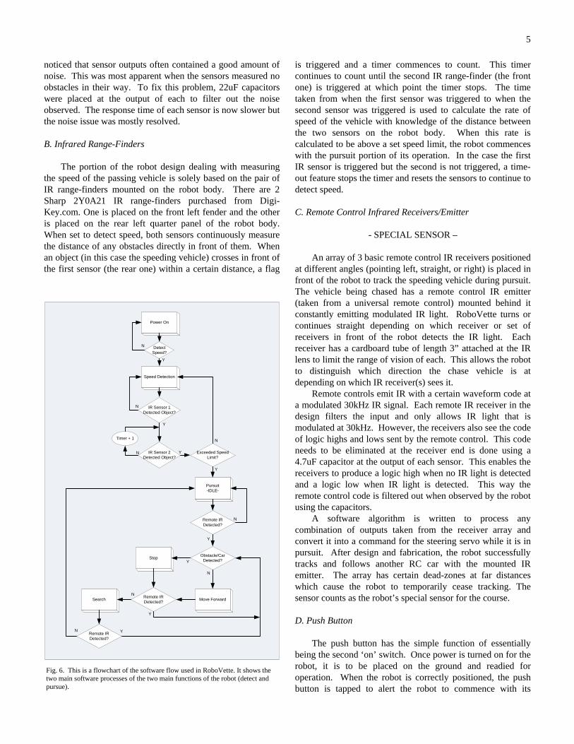
is triggered and a timer commences to count. This timer continues to count until the second IR range-finder (the front one) is triggered at which point the timer stops. The time taken from when the first sensor was triggered to when the second sensor was triggered is used to calculate the rate of speed of the vehicle with knowledge of the distance between the two sensors on the robot body. When this rate is calculated to be above a set speed limit, the robot commences with the pursuit portion of its operation. In the case the first IR sensor is triggered but the second is not triggered, a time-out feature stops the timer and resets the sensors to continue to detect speed.
C. Remote Control Infrared Receivers/Emitter
- SPECIAL SENSOR –
An array of 3 basic remote control IR receivers positioned at different angles (pointing left, straight, or right) is placed in front of the robot to track the speeding vehicle during pursuit. The vehicle being chased has a remote control IR emitter (taken from a universal remote control) mounted behind it constantly emitting modulated IR light. RoboVette turns or continues straight depending on which receiver or set of receivers in front of the robot detects the IR light. Each receiver has a cardboard tube of length 3” attached at the IR lens to limit the range of vision of each. This allows the robot to distinguish which direction the chase vehicle is at depending on which IR receiver(s) sees it.
Remote controls emit IR with a certain waveform code at a modulated 30kHz IR signal. Each remote IR receiver in the design filters the input and only allows IR light that is modulated at 30kHz. However, the receivers also see the code of logic highs and lows sent by the remote control. This code needs to be eliminated at the receiver end is done using a 4.7uF capacitor at the output of each sensor. This enables the receivers to produce a logic high when no IR light is detected and a logic low when IR light is detected. This way the remote control code is filtered out when observed by the robot using the capacitors.
A software algorithm is written to process any combination of outputs taken from the receiver array and convert it into a command for the steering servo while it is in pursuit. After design and fabrication, the robot successfully tracks and follows another RC car with the mounted IR emitter. The array has certain dead-zones at far distances which cause the robot to temporarily cease tracking. The sensor counts as the robot’s special sensor for the course. D. Push Button
The push button has the simple function of essentially being the second ‘on’ switch. Once power is turned on for the robot, it is to be placed on the ground and readied for operation. When the robot is correctly positioned, the push button is tapped to alert the robot to commence with its
Fig. 6. This is a flowchart of the software flow used in RoboVette. It shows the two main software processes of the two main functions of the robot (detect and pursue).
6
operation. The button is implemented to avoid false readings or false starts while powering on the robot. VI. BEHAVIORS
As mentioned in the introduction of this report, RoboVette has 2 main behaviors; speed monitoring/detection and vehicle tracking. The complete software algorithm flow is illustrated in the flowchart in Fig. 6. The individual functional behaviors associated with the robot are detailed in the subsections that follow.
A. Speed Monitoring and Detection
RoboVette’s first behavior deals with measuring the
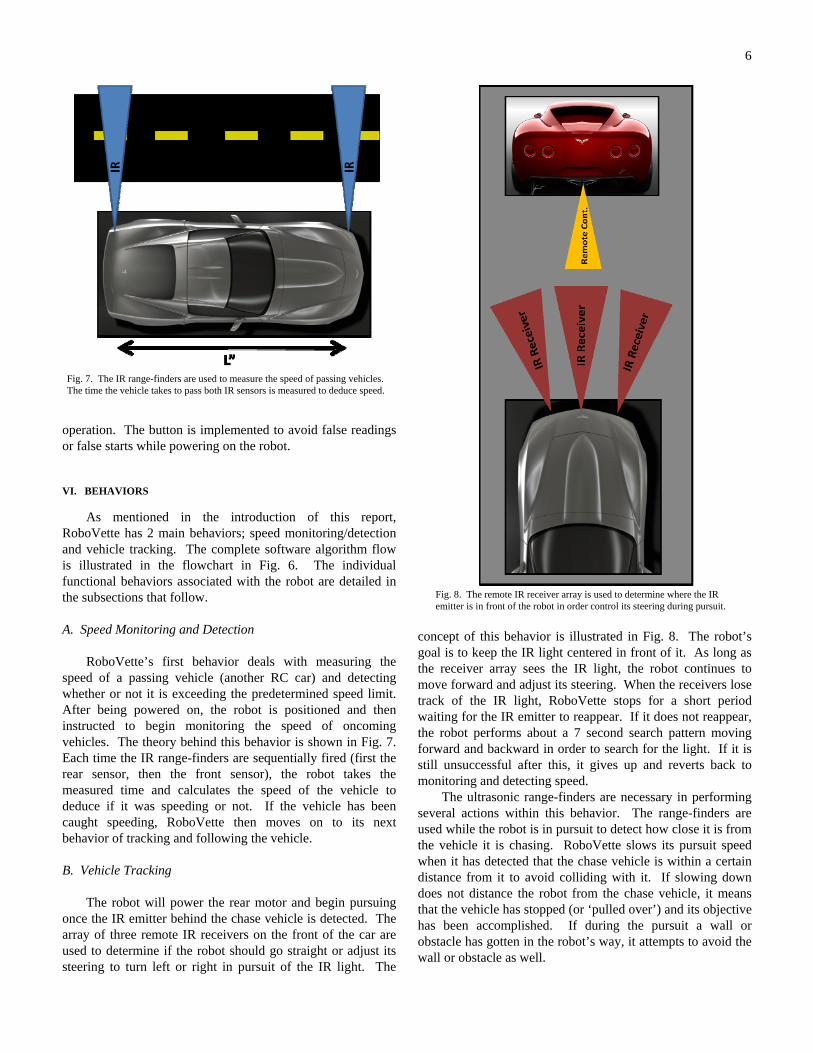
speed of a passing vehicle (another RC car) and detecting whether or not it is exceeding the predetermined speed limit. After being powered on, the robot is positioned and then instructed to begin monitoring the speed of oncoming vehicles. The theory behind this behavior is shown in Fig. 7. Each time the IR range-finders are sequentially fired (first the rear sensor, then the front sensor), the robot takes the measured time and calculates the speed of the vehicle to deduce if it was speeding or not. If the vehicle has been caught speeding, RoboVette then moves on to its next behavior of tracking and following the vehicle. B. Vehicle Tracking
The robot will power the rear motor and begin pursuing
once the IR emitter behind the chase vehicle is detected. The array of three remote IR receivers on the front of the car are used to determine if the robot should go straight or adjust its steering to turn left or right in pursuit of the IR light. The
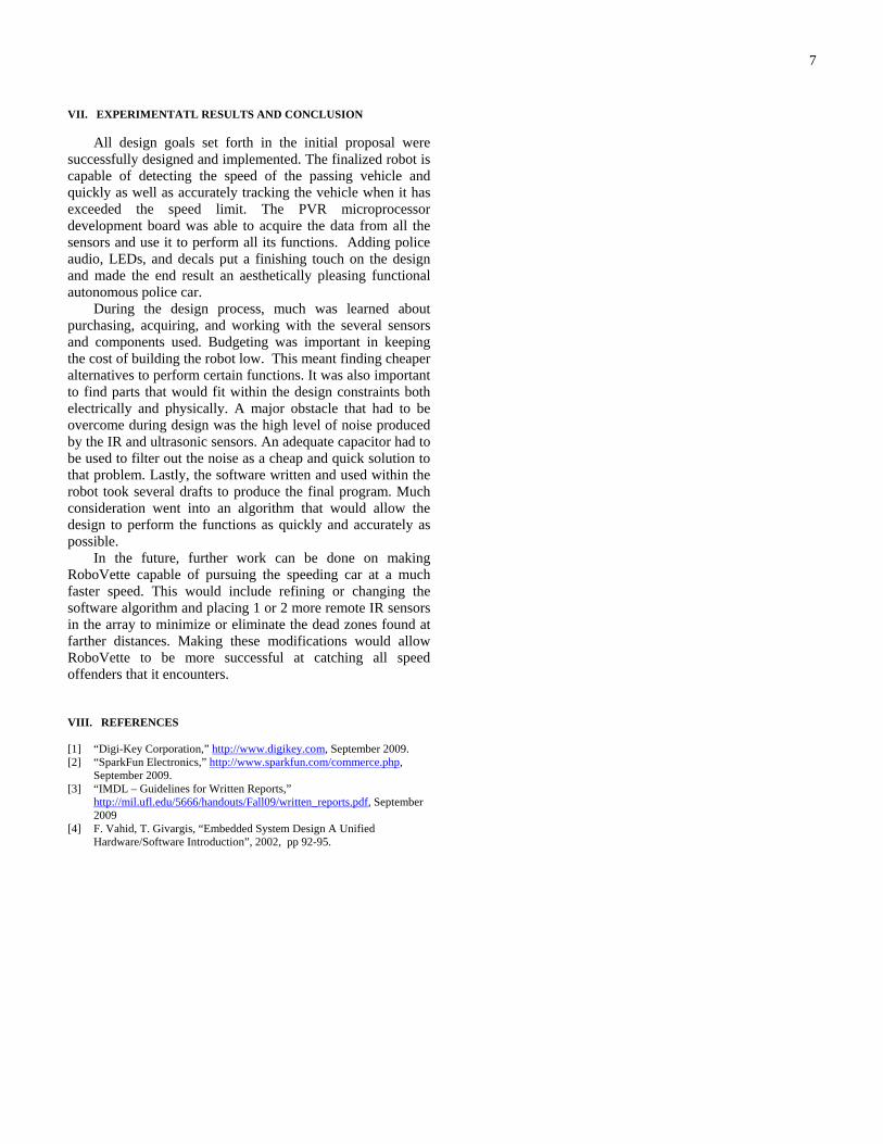
concept of this behavior is illustrated in Fig. 8. The robot’s goal is to keep the IR light centered in front of it. As long as the receiver array sees the IR light, the robot continues to move forward and adjust its steering. When the receivers lose track of the IR light, RoboVette stops for a short period waiting for the IR emitter to reappear. If it does not reappear, the robot performs about a 7 second search pattern moving forward and backward in order to search for the light. If it is still unsuccessful after this, it gives up and reverts back to monitoring and detecting speed.
The ultrasonic range-finders are necessary in performing several actions within this behavior. The range-finders are used while the robot is in pursuit to detect how close it is from the vehicle it is chasing. RoboVette slows its pursuit speed when it has detected that the chase vehicle is within a certain distance from it to avoid colliding with it. If slowing down does not distance the robot from the chase vehicle, it means that the vehicle has stopped (or ‘pulled over’) and its objective has been accomplished. If during the pursuit a wall or obstacle has gotten in the robot’s way, it attempts to avoid the wall or obstacle as well.
Fig. 8. The remote IR receiver array is used to determine where the IR emitter is in front of the robot in order control its steering during pursuit.
Fig. 7. The IR range-finders are used to measure the speed of passing vehicles. The time the vehicle takes to pass both IR sensors is measured to deduce speed.
7
VII. EXPERIMENTATL RESULTS AND CONCLUSION
All design goals set forth in the initial proposal were successfully designed and implemented. The finalized robot is capable of detecting the speed of the passing vehicle and quickly as well as accurately tracking the vehicle when it has exceeded the speed limit. The PVR microprocessor development board was able to acquire the data from all the sensors and use it to perform all its functions. Adding police audio, LEDs, and decals put a finishing touch on the design and made the end result an aesthetically pleasing functional autonomous police car.
During the design process, much was learned about purchasing, acquiring, and working with the several sensors and components used. Budgeting was important in keeping the cost of building the robot low. This meant finding cheaper alternatives to perform certain functions. It was also important to find parts that would fit within the design constraints both electrically and physically. A major obstacle that had to be overcome during design was the high level of noise produced by the IR and ultrasonic sensors. An adequate capacitor had to be used to filter out the noise as a cheap and quick solution to that problem. Lastly, the software written and used within the robot took several drafts to produce the final program. Much consideration went into an algorithm that would allow the design to perform the functions as quickly and accurately as possible.
In the future, further work can be done on making RoboVette capable of pursuing the speeding car at a much faster speed. This would include refining or changing the software algorithm and placing 1 or 2 more remote IR sensors in the array to minimize or eliminate the dead zones found at farther distances. Making these modifications would allow RoboVette to be more successful at catching all speed offenders that it encounters. VIII. REFERENCES
[1] “Digi-Key Corporation,” http://www.digikey.com, September 2009. [2] “SparkFun Electronics,” http://www.sparkfun.com/commerce.php,
September 2009. [3] “IMDL – Guidelines for Written Reports,”
http://mil.ufl.edu/5666/handouts/Fall09/written_reports.pdf, September 2009
[4] F. Vahid, T. Givargis, “Embedded System Design A Unified Hardware/Software Introduction”, 2002, pp 92-95.
8
IX. APPENDIX A
//***********************************************************************************************************/ /* --------------- */ /* >> RoboVette << */ /* --------------- */ /* */ /* Christian Davis */ /* EEL5666 - Intelligent Machines Design Lab */ /* Fall 2009 */ /* */ /* - Header file <PVR.h> and source file <PVR.c> were included with PVR board and modified for this project */ /***********************************************************************************************************/ #include <avr/io.h> #include <avr/interrupt.h> #include <stdlib.h> #include "PVR.h" void main(void) { /**************************/ // INITIALIZE BOARD // /**************************/ xmegaInit(); //Setup XMega delayInit(); //Setup delay functions ServoCInit(); //Setup PORTC Servos ServoDInit(); //Setup PORTD Servos ADCAInit(); //Setup PORTA analong readings lcdInit(); //Setup LCD on PORTK PORTF_DIR |= 0x07; //Set F0,1,2 (Motor Controller) as outputs PORTB_DIR |= 0x03; //Set B0,1 (Sonar Enable) as outputs PORTQ_DIR |= 0x0F; //Set Q0,1,2,3 (WaveShield signals) as outputs PORTH_DIR |= 0xFF; //Set H0 (Police LEDs) as outputs PORTF_PIN3CTRL &= 0xD7; //Set F3 to pull-down PORTF_PIN3CTRL |= 0x10; double speed; char c_time[16]; char portf; int SSpd = 1050; int IR1 = 0; int IR2 = 0; int pull = 0; int x; //Steering PWM Values// int C = 6; //Center int R = -28; //Right int L = 39; //Left int CR = -10; //Center-Right int CL = 23; //Center-Left //------------------// ServoC0(C); //Center wheels SBrake(); //Motor neutral Standby(); //Motor standby PORTB_OUT &= 0xFC; //Set PortB, pin 0,1 low (Turn off Sonar) S = 0; //////////////////////////// /**************************/ // POWER-ON // /**************************/ lcdString(" RoboVette"); //Display "RoboVette" on top line (Line 0) of LCD delay_ms(1500); play_start(); //Play start audio
9
lcdGoto(1,0); //Move LCD cursor to the second line (Line 1) of LCD lcdString("Powering On"); //Display "Power On" on second line x = 0; while (x < 5) { //Add dots (wait a little more to place robot down) delay_ms(1100); lcdString("."); x++; } x = 0; delay_ms(150); lcdData(0x01); //Clear screen lcdGoto(0,0); lcdString(" Ready"); delay_ms(1300); PORTH_OUT |= 0xC0; delay_ms(13000); lcdData(0x01); lcdGoto(0,0); lcdString(" Loitering "); portf = PORTF_IN; portf &= 0x08; while(portf == 0x00) { portf = PORTF_IN; portf &= 0x08; } //////////////////////////// /**************************/ // SPEED DETECTION // /**************************/ lcdData(0x01); lcdGoto(0,0); lcdString("Observing Speed"); play_chatter(); //Play chatter audio while(1) { IR1 = ADCA7(); delay_ms(30); IR1 = ADCA7(); if (IR1 >= 3000) { IR2 = 0; beginTimer(); while (IR2 < 3000) { IR2 = ADCA0(); delay_ms(5); IR2 = ADCA0(); if (time >= 3202) { break; } } stopTimer(); lcdData(0x01); lcdGoto(0,0); lcdString(" Detecting... "); if (time < 130) { lcdData(0x01); lcdGoto(0,0); lcdString("-PURSUE VEHICLE-"); time = time - 3; speed = 3500.0/time; itoa(speed, c_time, 10); lcdGoto(1,0); lcdString("Speed: "); lcdString(c_time); lcdString("cm/s"); break; } else { time = time - 3; speed = 3500.0/time;
10
itoa(speed, c_time, 10); lcdGoto(1,0); lcdString("Speed: "); lcdString(c_time); lcdString("cm/s"); delay_ms(1050); lcdData(0x01); lcdGoto(0,0); lcdString(" Do Not Pursue"); delay_ms(1000); lcdData(0x01); lcdGoto(0,0); lcdString("Observing Speed"); } } } //////////////////////////// /**************************/ // PURSUIT // /**************************/ ServoC0(C); PORTH_OUT |= 0x3F; play_siren(); //Play siren audio while(PORTJ_IN == 7); while(1) { pursuit: Run(); if (PORTJ_IN == 6) { //Center ServoC0(C); Sonar1(); Sonar2(); } else if (PORTJ_IN == 5) { //Left ServoC0(L); Sonar1(); Sonar2(); } else if (PORTJ_IN == 3) { //Right ServoC0(R); Sonar1(); Sonar2(); } else if (PORTJ_IN == 4) { //Center-Left ServoC0(CL); Sonar1(); Sonar2(); } else if (PORTJ_IN == 2) { //Center-Right ServoC0(CR); Sonar1(); Sonar2(); } else if (PORTJ_IN == 0) { //Left-Center-Right ServoC0(C); Sonar1(); Sonar2(); } if (PORTJ_IN == 7) { //No IR signal ServoC0(C); Standby(); y = 0; //Begin Search Maneuver while (y < 15000) { NOISonar1(); NOISonar2(); if (PORTJ_IN != 7) { goto pursuit; } y++;
11
} ServoC0(R); MotorD0(SSpd); Run(); MForward(); y = 0; NOISonar2(); while (y < 31600) { NOISonar2(); if (PORTJ_IN != 7) { goto pursuit; } y++; } SBrake(); y = 0; while (y < 540000) { if (PORTJ_IN != 7) { goto pursuit; } y++; } MReverse(); y = 0; while (y < 1281000) { if (PORTJ_IN != 7) { goto pursuit; } y++; } SBrake(); y = 0; while (y < 400000) { if (PORTJ_IN != 7) { goto pursuit; } y++; } ServoC0(L); MForward(); y = 0; NOISonar1(); while (y < 31600) { NOISonar1(); if (PORTJ_IN != 7) { goto pursuit; } y++; } SBrake(); y = 0; while (y < 540000) { if (PORTJ_IN != 7) { goto pursuit; } y++; } MReverse(); y = 0; while (y < 1281000) { if (PORTJ_IN != 7) { goto pursuit; } y++; } play_chatter(); play_chatter(); play_chatter(); play_chatter(); while (PORTJ_IN == 7) { ServoC0(C); Standby(); }
12
play_siren(); } else if ((S == 3) | (S == 4)) { pull++; if (pull > 1475) { play_pull(); pull = 0; x = 1; delay_ms(10040); play_bad(); while (PORTJ_IN != 7); } } else { pull = 0; } } //////////////////////////// } //**** FUNCTIONS ****// #include <avr/io.h> #include <avr/interrupt.h> #include "PVR.h" /********* * Xmega * *********/ void xmegaInit(void) { CCP = 0xD8; CLK_PSCTRL = 0x00; PORTQ_DIR = 0x01; //setup oscilllator OSC_CTRL = 0x02; //enable 32MHz internal clock while ((OSC_STATUS & 0x02) == 0); //wait for oscillator to be ready CCP = 0xD8; //write signature to CCP CLK_CTRL = 0x01; //select internal 32MHz RC oscillator } /********* * Timer * *********/ void beginTimer(void) { time = 0; //clear timer TCF1_CCB = 32000; //set COMB to be 1ms delay TCF1_CNT = 0; //reset counter TCF1_INTCTRLB = TCF1_INTCTRLB | 0x04; //enable low priority interrupt for delay } void stopTimer(void) { TCF1_INTCTRLB = TCF1_INTCTRLB & 0xFB; //disable interrupts } /********* * Delay * *********/ void delayInit(void) {
13
TCF1_CTRLA = 0x01; //set clock/1 TCF1_CTRLB = 0x31; //enable COMA and COMB, set to FRQ TCF1_INTCTRLB = 0x00; //turn off interrupts for COMA and COMB SREG |= CPU_I_bm; //enable all interrupts PMIC_CTRL |= 0x01; //enable all low priority interrupts } void delay_ms(int cnt) { delaycnt = 0; //set count value TCF1_CCA = 32000; //set COMA to be 1ms delay TCF1_CNT = 0; //reset counter TCF1_INTCTRLB = TCF1_INTCTRLB | 0x01; //enable low priority interrupt for delay while (cnt != delaycnt); //delay TCF1_INTCTRLB = TCF1_INTCTRLB & 0xFE; //disable interrupts } void delay_us(int cnt) { delaycnt = 0; //set counter TCF1_CCA = 32; //set COMA to be 1us delay TCF1_CNT = 0; //reset counter TCF1_INTCTRLB = 0x01; //enable low priority interrupt for delay while (cnt != delaycnt); //delay TCF1_INTCTRLB = 0x00; //disable interrupts } SIGNAL(TCF1_CCA_vect) { delaycnt++; } SIGNAL(TCF1_CCB_vect) { time++; } /******* * LCD * *******/ #define LCD PORTK_OUT #define LCDDDR PORTK_DIR void lcdDataWork(unsigned char c) { c &= 0xF0; //keep data bits, clear the rest c |= 0x08; //set E high LCD = c; //write to LCD delay_ms(2); //delay c ^= 0x08; //set E low LCD = c; //write to LCD delay_ms(2); //delay c |= 0x08; //set E high LCD = c; //write to LCD delay_ms(2); //delay } void lcdData(unsigned char c) { unsigned char cHi = c & 0xF0; //give cHi the high 4 bits of c unsigned char cLo = c & 0x0F; //give cLo the low 4 bits of c cLo = cLo * 0x10; //shift cLo left 4 bits lcdDataWork(cHi); lcdDataWork(cLo); } void lcdCharWork(unsigned char c) { c &= 0xF0; //keep data bits, clear the rest c |= 0x0A; //set E and RS high LCD = c; //write to LCD delay_ms(2); //delay
14
c ^= 0x08; //set E low LCD = c; //write to LCD delay_ms(2); //delay c |= 0x08; //set E high LCD = c; //write to LCD delay_ms(2); //delay } void lcdChar(unsigned char c) { unsigned char cHi = c & 0xF0; //give cHi the high 4 bits of c unsigned char cLo = c & 0x0F; //give cLo the low 4 bits of c cLo = cLo * 0x10; //shift cLo left 4 bits lcdCharWork(cHi); lcdCharWork(cLo); } void lcdString(unsigned char ca[]) { int i = 0; while (ca[i] != '\0') { lcdChar(ca[i++]); } } void lcdInt(int value) { int temp_val; int x = 10000; int leftZeros=5; if (value<0) { lcdChar('-'); value *= -1; } while (value / x == 0) { x/=10; leftZeros--; } while ((value > 0) || (leftZeros>0)) { temp_val = value / x; value -= temp_val * x; lcdChar(temp_val+ 0x30); x /= 10; leftZeros--; } while (leftZeros>0) { lcdChar(0+ 0x30); leftZeros--; } return; } void lcdGoto(int row, int col) { unsigned char pos; if ((col >= 0 && col <= 19) && (row >= 0 && row <= 3)) { pos = col; if (row == 1) pos += 0x40; else if (row == 2)
15
pos += 0x14; else if (row == 3) pos += 0x54; lcdData(0x80 + pos); } } void lcdInit(void) { delayInit(); //set up the delay functions LCDDDR = 0xFF; //set LCD port to outputs. delay_ms(20); //wait to ensure LCD powered up lcdDataWork(0x30); //put in 4 bit mode, part 1 delay_ms(10); //wait for lcd to finish lcdDataWork(0x30); //put in 4 bit mode, part 2 delay_ms(2); //wait for lcd to finish lcdData(0x32); //put in 4 bit mode, part 3 lcdData(0x2C); //enable 2 line mode lcdData(0x0C); //turn everything on lcdData(0x01); //clear LCD } /********* * Servo * *********/ void ServoCInit(void) { TCC0_CTRLA = 0x05; //set TCC0_CLK to CLK/64 TCC0_CTRLB = 0xF3; //Enable OC A, B, C, and D. Set to Single Slope PWM //OCnX = 1 from Bottom to CCx and 0 from CCx to Top TCC0_PER = 10000; //20ms / (1/(32MHz/64)) = 10000. PER = Top TCC1_CTRLA = 0x05; //set TCC1_CLK to CLK/64 TCC1_CTRLB = 0x33; //Enable OC A and B. Set to Single Slope PWM //OCnX = 1 from Bottom to CCx and 0 from CCx to Top TCC1_PER = 10000; //20ms / (1/(32MHz/64)) = 10000. PER = Top PORTC_DIR = 0x3F; //set PORTC5:0 to output TCC0_CCA = 0; //PWMC0 off TCC0_CCB = 0; //PWMC1 off TCC0_CCC = 0; //PWMC2 off TCC0_CCD = 0; //PWMC3 off TCC1_CCA = 0; //PWMC4 off TCC1_CCB = 0; //PWMC5 off } void ServoDInit(void) { TCD0_CTRLA = 0x05; //set TCC0_CLK to CLK/64 TCD0_CTRLB = 0xF3; //Enable OC A, B, C, and D. Set to Single Slope PWM //OCnX = 1 from Bottom to CCx and 0 from CCx to Top TCD0_PER = 10000; //20ms / (1/(32MHz/64)) = 10000. PER = Top TCD1_CTRLA = 0x05; //set TCC1_CLK to CLK/64 TCD1_CTRLB = 0x33; //Enable OC A and B. Set to Single Slope PWM //OCnX = 1 from Bottom to CCx and 0 from CCx to Top TCD1_PER = 10000; //20ms / (1/(32MHz/64)) = 10000. PER = Top PORTD_DIR = 0x3F; //set PORTC5:0 to output TCD0_CCA = 0; //PWMC0 off TCD0_CCB = 0; //PWMC1 off TCD0_CCC = 0; //PWMC2 off TCD0_CCD = 0; //PWMC3 off TCD1_CCA = 0; //PWMC4 off TCD1_CCB = 0; //PWMC5 off } void ServoC0(int value) { if (value > 100) //cap at +/- 100 value = 100; // -100 => 1ms else if (value < -100) // 0 => 1.5ms value = -100; // 100 => 2ms value *= 5; //multiply value by 2.5 value /= 2; // new range +/- 250 TCC0_CCA = (750 + value); //Generate PWM.
16
} void MotorD0(int value) { value *= 5; //multiply value by 2.5 value /= 2; // new range +/- 250 TCD0_CCA = (750 + value); //Generate PWM. } /******************* * Motor Operation * *******************/ //{IN1=L,IN2=H}-Forward {IN1=H,IN2=L}-Reverse// void Run(void) //Motor On { PORTF_OUT |= 0x04; //Set PortF, pin 2 high (Run) } void Standby(void) //Motor Off { PORTF_OUT &= 0xFB; //Set PortF, pin 2 low (Standby) } void MForward(void) //Forward Direction { PORTF_OUT &= 0xFE; //Set PortF, pin0 LOW (IN1 = 0) PORTF_OUT |= 0x02; //Set PortF, pin1 HIGH (IN2 = 1) } void MReverse(void) //Reverse Direction { PORTF_OUT |= 0x01; //Set PortF, pin0 HIGH (IN1 = 1) PORTF_OUT &= 0xFD; //Set PortF, pin1 LOW (IN2 = 0) } void SBrake(void) //Short Brake { PORTF_OUT |= 0x01; //Set PortF, pin0 HIGH (IN1 = 1) PORTF_OUT |= 0x02; //Set PortF, pin1 HIGH (IN2 = 1) } void Stop(void) //Stop Motor { PORTF_OUT &= 0xFE; //Set PortF, pin0 LOW (IN1 = 0) PORTF_OUT &= 0xFD; //Set PortF, pin1 LOW (IN2 = 0) } /******** * ADCA * ********/ void ADCAInit(void) { ADCA_CTRLB = 0x00; //12bit, right adjusted ADCA_REFCTRL = 0x10; //set to Vref = Vcc/1.6 = 2.0V (approx) ADCA_CH0_CTRL = 0x01; //set to single-ended ADCA_CH0_INTCTRL = 0x00; //set flag at conversion complete. Disable interrupt ADCA_CH0_MUXCTRL = 0x08; //set to Channel 1 ADCA_CTRLA |= 0x01; //Enable ADCA } int ADCA0(void) { ADCA_CH0_MUXCTRL = 0x00; //Set to Pin 0 ADCA_CTRLA |= 0x04; //Start Conversion on ADCA Channel 0 while ((ADCA_CH0_INTFLAGS & 0x01) != 0x01); //wait for conversion to complete int value = ADCA_CH0_RES; //grab result return value; //return result } int ADCA1(void)
17
{ ADCA_CH0_MUXCTRL = 0x08; //Set to Pin 1 ADCA_CTRLA |= 0x04; //Start Conversion on ADCA Channel 0 while ((ADCA_CH0_INTFLAGS & 0x01) != 0x01); //wait for conversion to complete int value = ADCA_CH0_RES; //grab result return value; //return result } int ADCA2(void) { ADCA_CH0_MUXCTRL = 0x10; //Set to Pin 2 ADCA_CTRLA |= 0x04; //Start Conversion on ADCA Channel 0 while ((ADCA_CH0_INTFLAGS & 0x01) != 0x01); //wait for conversion to complete int value = ADCA_CH0_RES; //grab result return value; //return result } int ADCA3(void) { ADCA_CH0_MUXCTRL = 0x18; //Set to Pin 3 ADCA_CTRLA |= 0x04; //Start Conversion on ADCA Channel 0 while ((ADCA_CH0_INTFLAGS & 0x01) != 0x01); //wait for conversion to complete int value = ADCA_CH0_RES; //grab result return value; //return result } /********* * Sonar * *********/ void Sonar1(void) { int US = 0; long US_T = 0; int N = 5; int i; int HSpd = 1350; int FSpd = 2475; if (S != 4) { //*Eliminate IF statement if steering becomes lazy and add to ELSE IFs PORTB_OUT |= 0x02; //Set PortB, pin1 HIGH (Left Sonar (1) On) delay_us(20); //Startup delay US = ADCA1(); //Read in intial value for (i=0;i<N;i++) { //Simple running average filter for sonar US = ADCA1(); US_T = US_T + US; } US = US_T/N; delay_ms(3); //*Adjust if car freezes after detecting obstacle if (US < 400) { //Car/obstacle directly in front. STOP SBrake(); if (S == 1) { //Soft brake (short reverse) MReverse(); delay_ms(60); SBrake(); S = 3; } else if (S == 2) { //Hard brake (long reverse) MReverse(); delay_ms(125); SBrake(); S = 3; } } else if ((US >= 400) & (US < 406)) { //Do nothing at this distance SBrake(); } else if ((US >= 406) & (US < 426)) { //Slow down if car/obstacle near MotorD0(HSpd); MForward(); delay_ms(20); S = 1; }
18
else { //Full speed if nothing near MotorD0(FSpd); MForward(); S = 2; } PORTB_OUT &= 0xFD; //Set PortB, pin1 LOW (Left Sonar (1) Off) } } void Sonar2(void) { int US = 0; long US_T = 0; int N = 5; int i; int HSpd = 1350; int FSpd = 2475; if (S != 3) { //*Eliminate IF statement if steering becomes lazy and add to ELSE IFs PORTB_OUT |= 0x01; //Set PortB, pin0 HIGH (Right Sonar (2) On) delay_us(20); //Startup delay US = ADCA2(); //Read in initial value for (i=0;i<N;i++) { //Simple running average filter for sonar US = ADCA2(); US_T = US_T + US; } US = US_T/N; delay_ms(3); //*Adjust if car freezes after detecting obstacle if (US < 400) { //Car/obstacle directly in front. SIOP SBrake(); if (S == 1) { //Soft brake (short reverse) MReverse(); delay_ms(60); SBrake(); S = 4; } else if (S == 2) { //Hard brake (long reverse) MReverse(); delay_ms(125); SBrake(); S = 4; } } else if ((US >= 400) & (US < 406)) { //Do nothing at this distance SBrake(); } else if ((US >= 406) & (US < 426)) { //Slow down if car/obstacle near MotorD0(HSpd); MForward(); delay_ms(20); S = 1; } else { //Full speed if nothing near MotorD0(FSpd); MForward(); S = 2; } PORTB_OUT &= 0xFE; //Set PortB, pin0 LOW (Right Sonar (2) Off) } } void NOISonar1(void) { int US = 0; long US_T = 0; int N, i; PORTB_OUT |= 0x02; //Set PortB, pin1 HIGH (Left Sonar (1) On) delay_us(20); //Startup delay US = ADCA1(); //Read in intial value N = 5; for (i=0;i<N;i++) { //Simple running average filter for sonar US = ADCA1();
19
US_T = US_T + US; } US = US_T/N; if (US < 400) { //Brake if obstacle directly ahead (reverse) SBrake(); delay_ms(10); MReverse(); Run(); delay_ms(85); SBrake(); y = 2000000; //Exit current search maneuver function } PORTB_OUT &= 0xFD; //Set PortB, pin1 LOW (Left Sonar (1) Off) } void NOISonar2(void) { int US = 0; long US_T = 0; int N, i; PORTB_OUT |= 0x01; //Set PortB, pin0 HIGH (Right Sonar (2) On) delay_us(20); //Startup delay US = ADCA2(); //Read in initial value N = 5; for (i=0;i<N;i++) { //Simple running average filter for sonar US = ADCA2(); US_T = US_T + US; } US = US_T/N; if (US < 400) { //Brake if obstacle directly ahead (reverse) SBrake(); delay_ms(10); MReverse(); Run(); delay_ms(85); SBrake(); y = 2000000; //Exit current search maneuver function } PORTB_OUT &= 0xFE; //Set PortB, pin0 LOW (Right Sonar (2) Off) } /********* * Audio * *********/ void play_start(void) { PORTQ_OUT &= 0xF8; //Set PortQ, pin2,1,0 LOW (WS Pin9,8,7) PORTQ_OUT |= 0x08; //Set PortQ, pin3 HIGH (WS Pin 6) PORTQ_OUT |= 0x01; //Set PortQ, pin0 HIGH (WS Pin 9) //Send command delay_ms(5); PORTQ_OUT &= 0xFE; //Set PortQ, pin0 LOW (WS Pin 9) //Finish send } void play_chatter(void) { PORTQ_OUT &= 0xF4; //Set PortQ, pin3,1,0 LOW (WS Pin9,8,6) PORTQ_OUT |= 0x04; //Set PortQ, pin3 HIGH (WS Pin 7) PORTQ_OUT |= 0x01; //Set PortQ, pin0 HIGH (WS Pin 9) //Send command delay_ms(5); PORTQ_OUT &= 0xFE; //Set PortQ, pin0 LOW (WS Pin 9) //Finish send } void play_siren(void) { PORTQ_OUT &= 0xFC; //Set PortQ, pin1,0 LOW (WS Pin9,8) PORTQ_OUT |= 0x0C; //Set PortQ, pin3,2 HIGH (WS Pin7,6) PORTQ_OUT |= 0x01; //Set PortQ, pin0 HIGH (WS Pin 9) //Send command
20
delay_ms(5); PORTQ_OUT &= 0xFE; //Set PortQ, pin0 LOW (WS Pin 9) //Finish send } void play_pull(void) { PORTQ_OUT &= 0xF2; //Set PortQ, pin3,2,0 LOW (WS Pin9,7,6) PORTQ_OUT |= 0x02; //Set PortQ, pin1 HIGH (WS Pin 8) PORTQ_OUT |= 0x01; //Set PortQ, pin0 HIGH (WS Pin 9) //Send command delay_ms(5); PORTQ_OUT &= 0xFE; //Set PortQ, pin0 LOW (WS Pin 9) //Finish send } void play_bad(void) { PORTQ_OUT &= 0xFA; //Set PortQ, pin3,1,0 LOW (WS Pin9,8,6) PORTQ_OUT |= 0x0A; //Set PortQ, pin3 HIGH (WS Pin 7) PORTQ_OUT |= 0x01; //Set PortQ, pin0 HIGH (WS Pin 9) //Send command delay_ms(5); PORTQ_OUT &= 0xFE; //Set PortQ, pin0 LOW (WS Pin 9) //Finish send }