jonathan gamoneda eel 5666 – intelligent machines design ...€¦ · jonathan gamoneda eel 5666...
TRANSCRIPT
Jonathan Gamoneda EEL 5666 – Intelligent Machines Design Lab
Fall 2001 December 4, 2001
Table of Contents TABLE OF CONTENTS…………………………………………………………2 ABSTRACT……………………………………………………………………….3 EXECUTIVE SUMMARY……………………………………………………….4 INTRODUCTION………………………………………………………………..5 INTEGRATED SYSTEM………………………………………………………..5 MOBILE PLATFORM…………………………………………………………..6 ACTUATION ……………………………………………………………………7 SENSORS…………………………………………………………………………8 BEHAVIORS ……………………………………………………………………15 EXPERIMENTAL LAYOUT and RESULTS…………………………………16 CONCLUSION …………………………………………………………………..17 DOCUMENTATION…………………………………………………………….19 APPENDIX……………………………………………………………………….20 PICTURES………………………………………………………………………..28
ABSTRACT
The purpose of the lil golfing buddy©™ is to construct an intelligent mobile
robot to place a golf ball on a tee. The robot will go around a small area of artificial
grass looking for a tee on the ground. The robot will also be able to avoid larger
obstacles. After it has found the tee it will approach it and then position the robot so
an arm can be deployed to place the ball on the tee. Then the robot will back up and
wait for the sound of a golf ball being hit. After it hears the sound it will try to place
another ball on the tee.
EXECUTIVE SUMMARY
The lil Golfing buddy was to design to help any golfer practice on artificial
grass at any driving range across the United States of America. The lil Golfing
Buddy was aimed at helping the golfers focus on driving the golf ball with out having
to worrying about bending down and keep putting another golf ball on the tee.
The lil Golfing Buddy was built to work in a small area about 6 feet by 6 feet.
With in a minute the lil Golfing buddy will locate the tee and then attempt to place a
golf on top of the tee. The Golfing Buddy will then back up and wait to hear the
sound of a golf ball being hit. (Please reload the Golfing Buddy manually before
hitting the teed ball) Upon hearing the sound it will repeat the process.
The lil Golfing Buddy is powered with eight 1.2V NICD batteries and motion
is obtained with two partially modified servos and a caster wheel in the rear to
maintain balance. The lil Golfing Buddy is controlled with an 68HC11 based board,
the Mekatronix MRC11, and the MRSX01, its accompanying expansion board.
The lil Golfing Buddy uses 5 different sensors to complete its task. The IR
Sharp Range IR’s are used to located the tee. The Sharp Can IR detectors will be
used for obstacle avoidance. The cds cells will be used in conjunction with the laser
beams to make a break beam sensor. The break beam sensor will be placed in an X-Y
coordinate system to find the exact location of the tee. I simple sound circuit using a
LM386 Op-amp is used to detect when the golf ball is being hit. A thermo resistor is
used to determine the temperature and if the golfer needs to take a break.
INTRODUCTION
Have you even been in this scenario? You have not golfed in a while and want to
get some practice. You head on over to the local driving r ange for some swings and of
course to see if you can hit the golf ball ranger, which is collecting the balls. At the
driving range you earnestly purchase the Jumbo bucket of golf balls not thinking of how
out of shape you are or how awful your driving is. By the time you are half way through
with the jumbo bucket of golf balls you are tired of constantly re-teeing your golf ball.
This is where the lil Golfing Buddy©™ can be used. While you are busy watching your
balls hooking or slicing, the lil Golfing buddy©™ will be placing another golf ball on
your tee.
INTEGRATED SYSTEMS
The micro controller of the lil Golfing Buddy©™ is a Motorola 68HC11 based
board from Mekatronix, part number MRC11. Also used on the lil Golfing Buddy is the
MSRX01 a sensory board from Mekatronix’s that connects to the MRC11 board. The
MSRX01 or expansion board will be used to gather information from the sensory devices
(IR, sound, light beam, and bump) as well as control 4 servos and various LEDs.
There will be at least 2 light beam sensors (placed in an x-y coordinate system)
used to find the location of the tee. The system will consist of cds cells to determine if
either beam has been broken. I am going to use 2 different laser-pointing pens for the
light beams. They will be turn on prior to starting the robot using a DPDT switch.
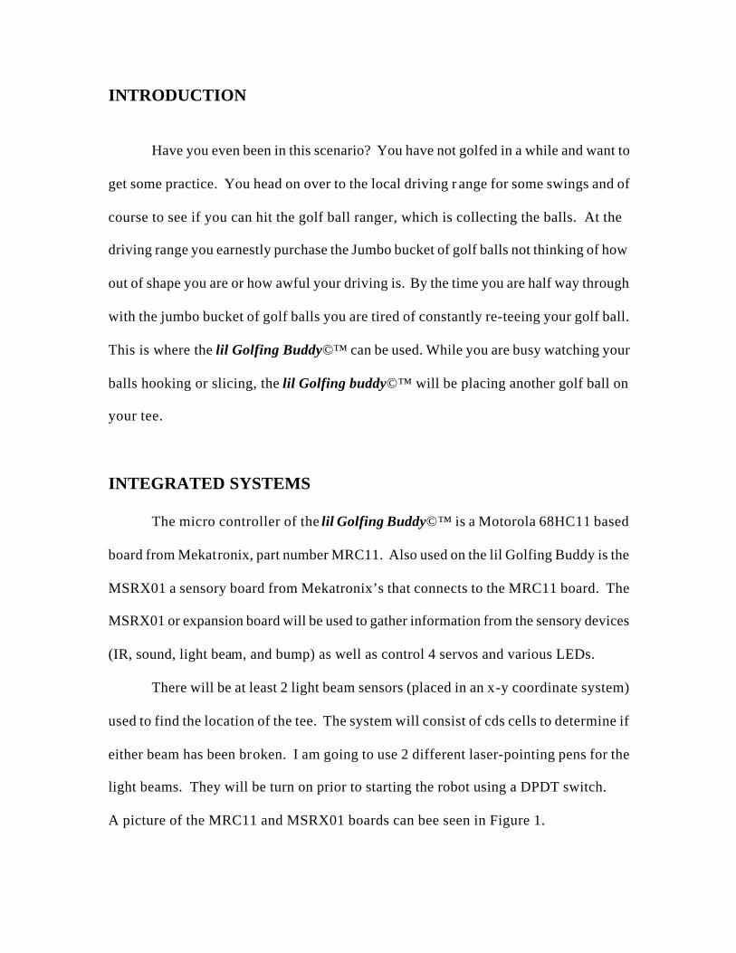
A picture of the MRC11 and MSRX01 boards can bee seen in Figure 1.
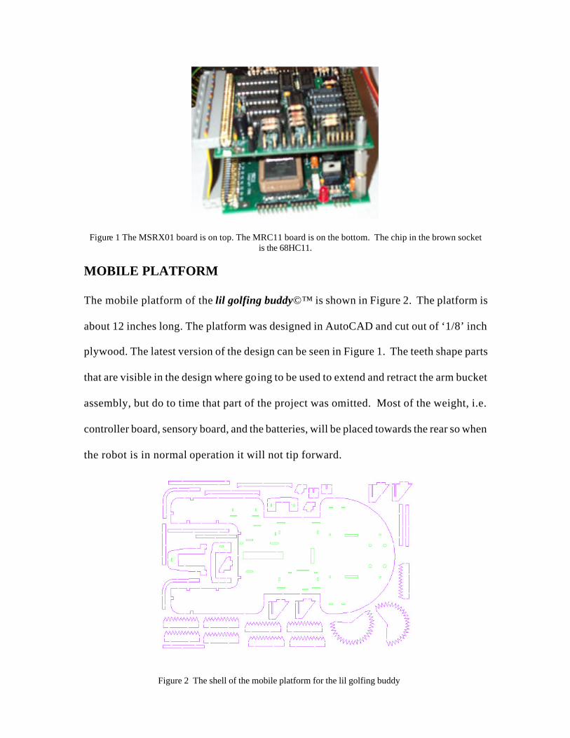
Figure 1 The MSRX01 board is on top. The MRC11 board is on the bottom. The chip in the brown socket is the 68HC11.
MOBILE PLATFORM
The mobile platform of the lil golfing buddy©™ is shown in Figure 2. The platform is
about 12 inches long. The platform was designed in AutoCAD and cut out of ‘1/8’ inch
plywood. The latest version of the design can be seen in Figure 1. The teeth shape parts
that are visible in the design where going to be used to extend and retract the arm bucket
assembly, but do to time that part of the project was omitted. Most of the weight, i.e.
controller board, sensory board, and the batteries, will be placed towards the rear so when
the robot is in normal operation it will not tip forward.
Figure 2 The shell of the mobile platform for the lil golfing buddy
ACTUATION
The body of the robot will be moved by using two diamond servos (bought from
mekatronix see documentation) mounted on the platform in Figure 2. The two servos
were partially modified to allow them to turn a complete 360 degrees. The two drive
servos had a rated torque of 43oz/in. A caster wheel is going to be in placed in the rear of
the robot to complete the suspension and balance out the design.
Programming the robot to move was a snap after I made some simple functions in
C. I made a function forward() that allowed the robot to move forward. Please view
Appendix for the other functions that were used to move and control the lil Golfing
Buddy’s Systems.
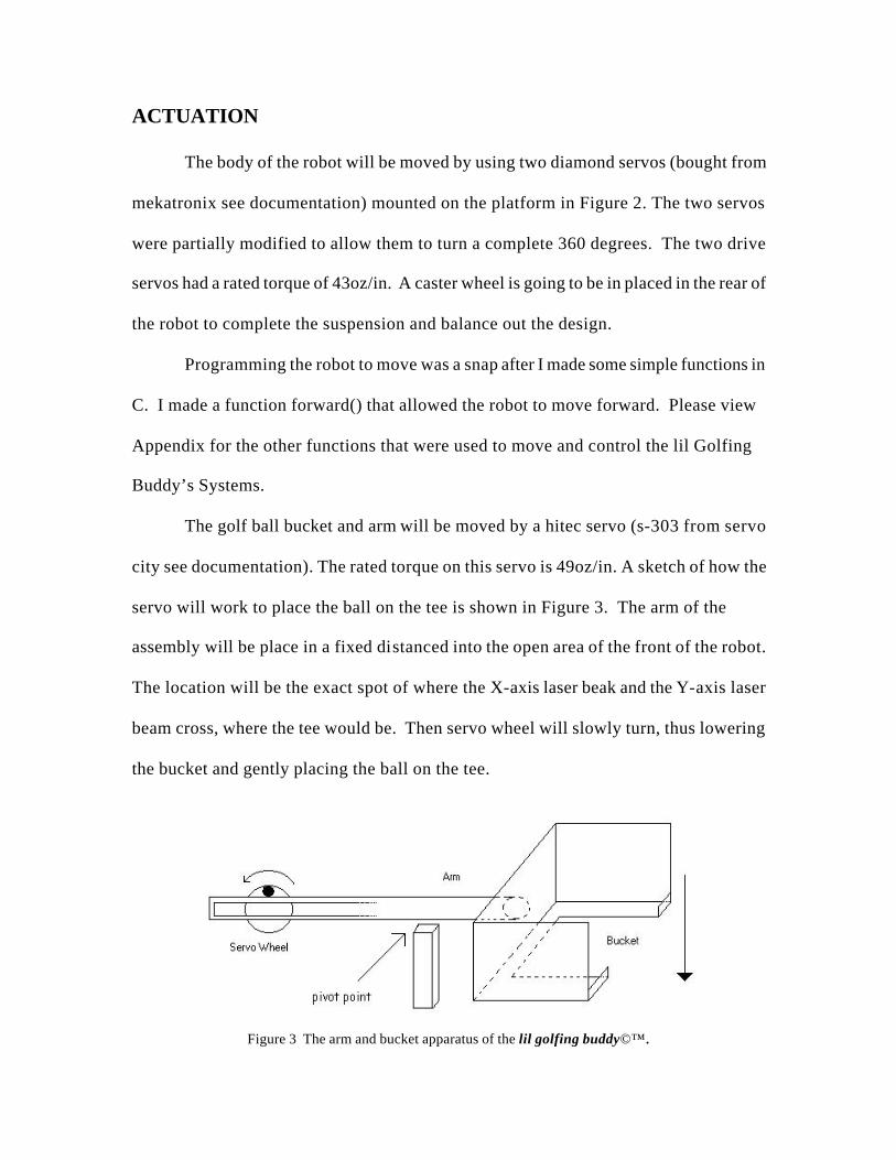
The golf ball bucket and arm will be moved by a hitec servo (s-303 from servo
city see documentation). The rated torque on this servo is 49oz/in. A sketch of how the
servo will work to place the ball on the tee is shown in Figure 3. The arm of the
assembly will be place in a fixed distanced into the open area of the front of the robot.
The location will be the exact spot of where the X-axis laser beak and the Y-axis laser
beam cross, where the tee would be. Then servo wheel will slowly turn, thus lowering
the bucket and gently placing the ball on the tee.
Figure 3 The arm and bucket apparatus of the lil golfing buddy©™.
A final servo was used to place the Y-axis’s cds cell into position when ready.
This was a small mini servo, a hitec HS-55 Feather Servo from servo city. The rated
torque on the servo is 18.05oz in.
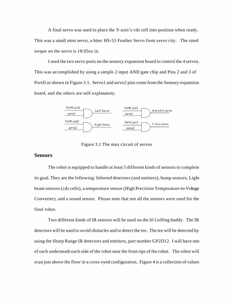
I used the two servo ports on the sensory expansion board to control the 4 servos.
This was accomplished by using a simple 2 input AND gate chip and Pins 2 and 3 of
PortD as shown in Figure 3.1. Servo1 and servo2 pins come from the Sensory expansion
board, and the others are self-explanatory.
Figure 3.1 The mux circuit of servos
Sensors
The robot is equipped to handle at least 5 different kinds of sensors to complete
its goal. They are the following: Inferred detectors (and emitters), bump sensors, Light
beam sensors (cds cells), a temperature sensor (High Precision Temperature-to-Voltage
Converter), and a sound sensor. Please note that not all the sensors were used for the
final robot.
Two different kinds of IR sensors will be used on the lil Golfing buddy. The IR
detectors will be used to avoid obstacles and to detect the tee. The tee will be detected by
using the Sharp Range IR detectors and emitters, part number GP2D12. I will have one
of each underneath each side of the robot near the front tips of the robot. The robot will
scan just above the floor in a cross-eyed configuration. Figure 4 is a collection of values
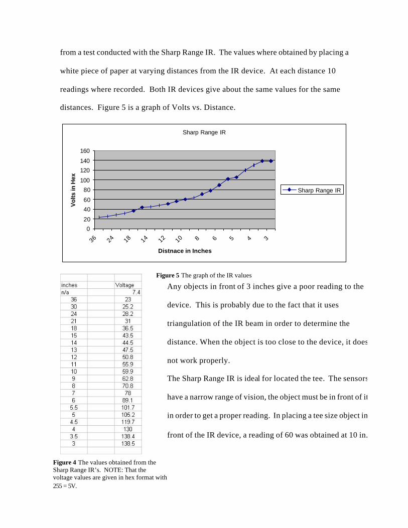
from a test conducted with the Sharp Range IR. The values where obtained by placing a
white piece of paper at varying distances from the IR device. At each distance 10
readings where recorded. Both IR devices give about the same values for the same
distances. Figure 5 is a graph of Volts vs. Distance.
Sharp Range IR
0
20
40
60
80
100
120
140
160
36 24 18 14 12 10 8 6 5 4 3
Distnace in Inches
Vol
ts in
Hex
Sharp Range IR
Figure 5 The graph of the IR values
Any objects in front of 3 inches give a poor reading to the
device. This is probably due to the fact that it uses
triangulation of the IR beam in order to determine the
distance. When the object is too close to the device, it does
not work properly.
The Sharp Range IR is ideal for located the tee. The sensors
have a narrow range of vision, the object must be in front of it
in order to get a proper reading. In placing a tee size object in
front of the IR device, a reading of 60 was obtained at 10 in.
Figure 4 The values obtained from the Sharp Range IR’s. NOTE: That the voltage values are given in hex format with 255 = 5V.
That is about the same reading as with the white piece of paper, which was 59.9.
A moving tee sized object test was also conducted (at about the speed that the robot will
drive around and look for the tee) over the area the IR detector vision. It was able to
distinguish the tee, the following readings are: 11, 8 , 10 ,18 ,45 ,58 ,4 ,4 10, 13.
Two more IR detectors will be used to avoid obstacles. While the more accurate
sharp Rangers scan the floor, the older sharp cans, part number GP1U5, will be used to
collision avoidance. The sharp can’s will be placed on the topside of the front tips of the
robot to determine if the robot is going towards a tee or a larger object. And as a bonus,
the Sharp Range IR’s and the sharp cans run on different frequencies, so each set of IR
detectors should not interfere with the other.
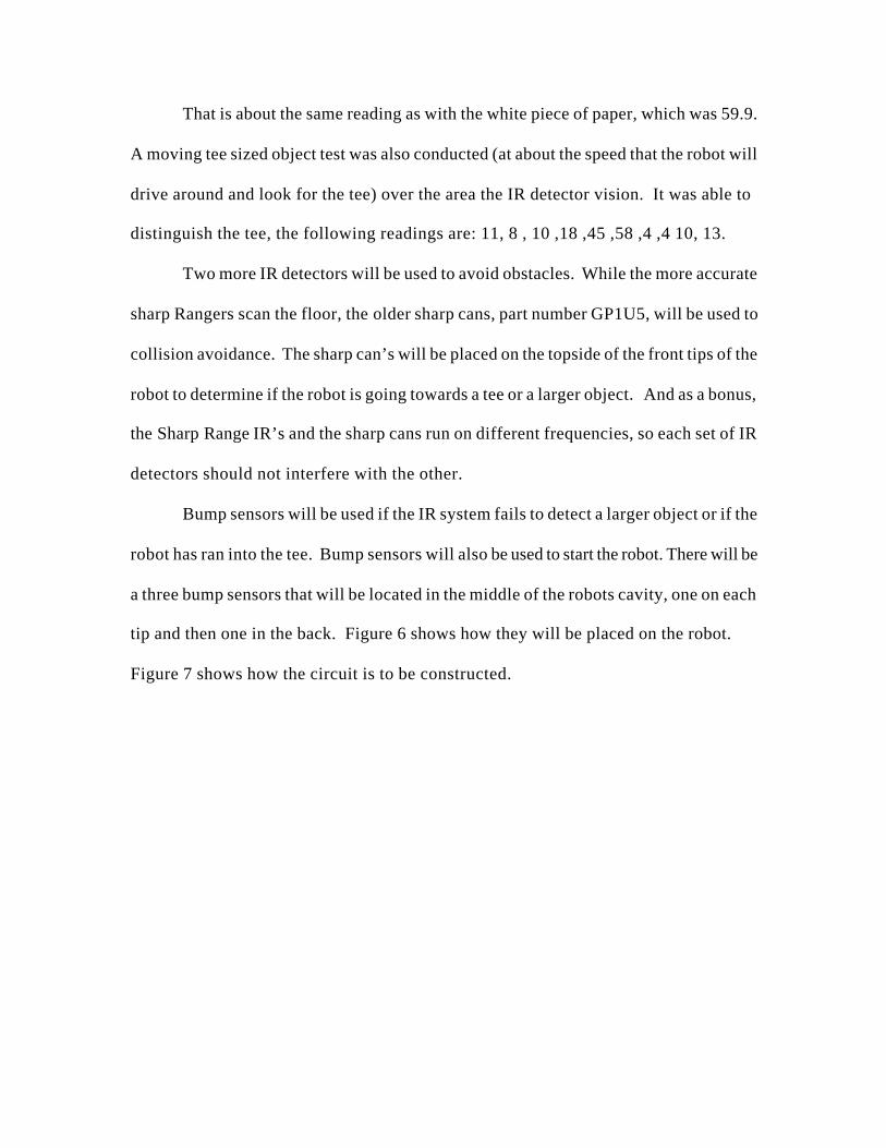
Bump sensors will be used if the IR system fails to detect a larger object or if the
robot has ran into the tee. Bump sensors will also be used to start the robot. There will be
a three bump sensors that will be located in the middle of the robots cavity, one on each
tip and then one in the back. Figure 6 shows how they will be placed on the robot.
Figure 7 shows how the circuit is to be constructed.
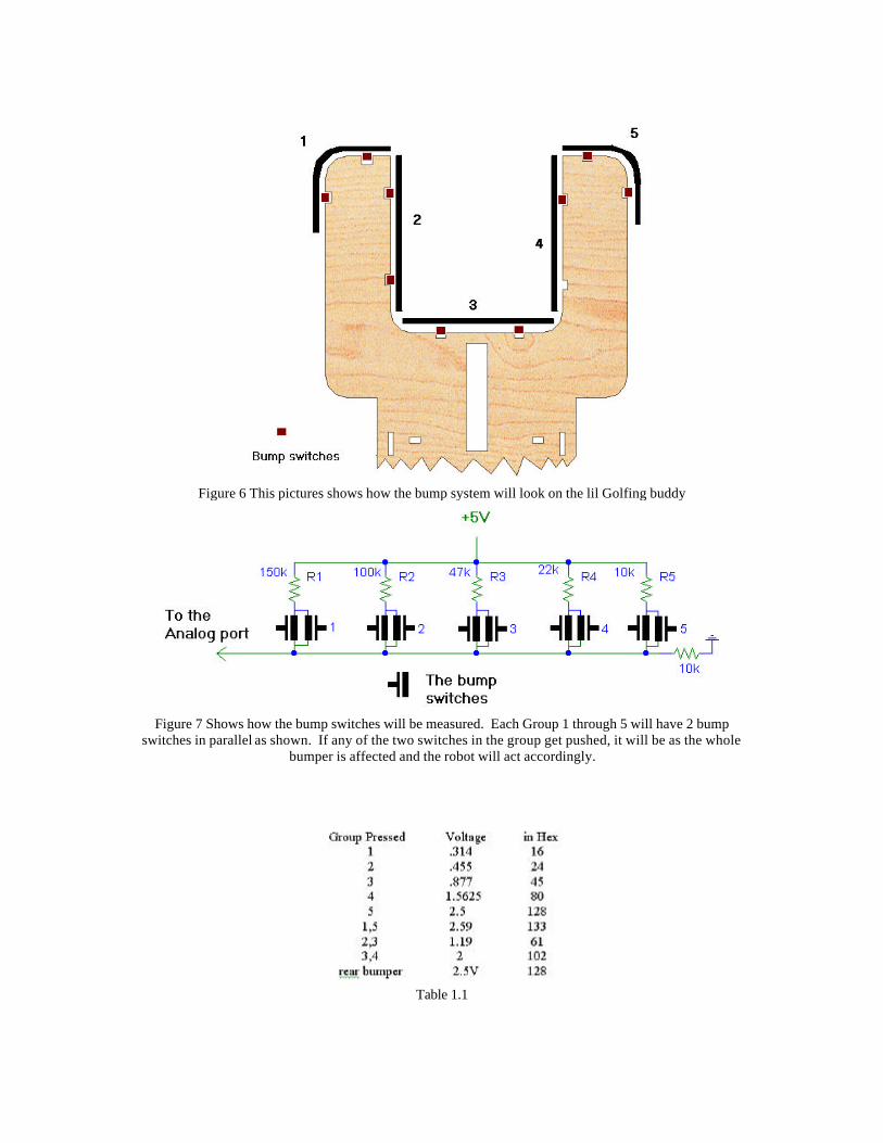
Figure 6 This pictures shows how the bump system will look on the lil Golfing buddy
Figure 7 Shows how the bump switches will be measured. Each Group 1 through 5 will have 2 bump
switches in parallel as shown. If any of the two switches in the group get pushed, it will be as the whole bumper is affected and the robot will act accordingly.
Table 1.1
The Table 1.1 is all the expected combinations that the bump switches may be
pressed during normal operation. R1 is actually 149.3kΩ, R2 is 98.3kΩ, R3 is 47.2kΩ,
R4 is 21.8kΩ and R5 is 9.9kΩ. The common resistor is 10kΩ. The values in the table
reflect the actual resistor values.
The back bumper is a simple voltage divider circuit. It is the last resistor R5 and
the 10k resistor that is tied to ground in Figure 7 with two bump switches in parallel.
When none of the switches are press, the voltage read 0V, when it is pressed it read 2.5V
or 128hex.
The light beam sensors will be made from 2 laser pointing pens, 2 cds cells, and 2
resistors that help make up a voltage divider circuit with the cds cells. This is new and
unique because no one has used two laser break beams as an x-y coordinate system. The
break beam sensor will be constructed by aiming the laser into the cds cell. This will
allow the robot to determine the exact location of the tee. Figure 8 shows how the Laser
pens and the cds cells will be placed on the robot.
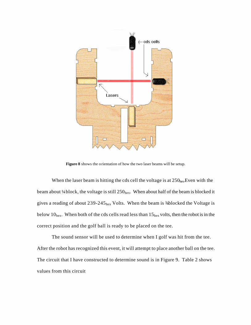
Figure 8 shows the orientation of how the two laser beams will be setup.
When the laser beam is hitting the cds cell the voltage is at 250hex.Even with the
beam about ¼ block, the voltage is still 250hex. When about half of the beam is blocked it
gives a reading of about 239-245hex Volts. When the beam is ¾ blocked the Voltage is
below 10hex. When both of the cds cells read less than 15hex volts, then the robot is in the
correct position and the golf ball is ready to be placed on the tee.
The sound sensor will be used to determine when I golf was hit from the tee.
After the robot has recognized this event, it will attempt to place another ball on the tee.
The circuit that I have constructed to determine sound is in Figure 9. Table 2 shows
values from this circuit
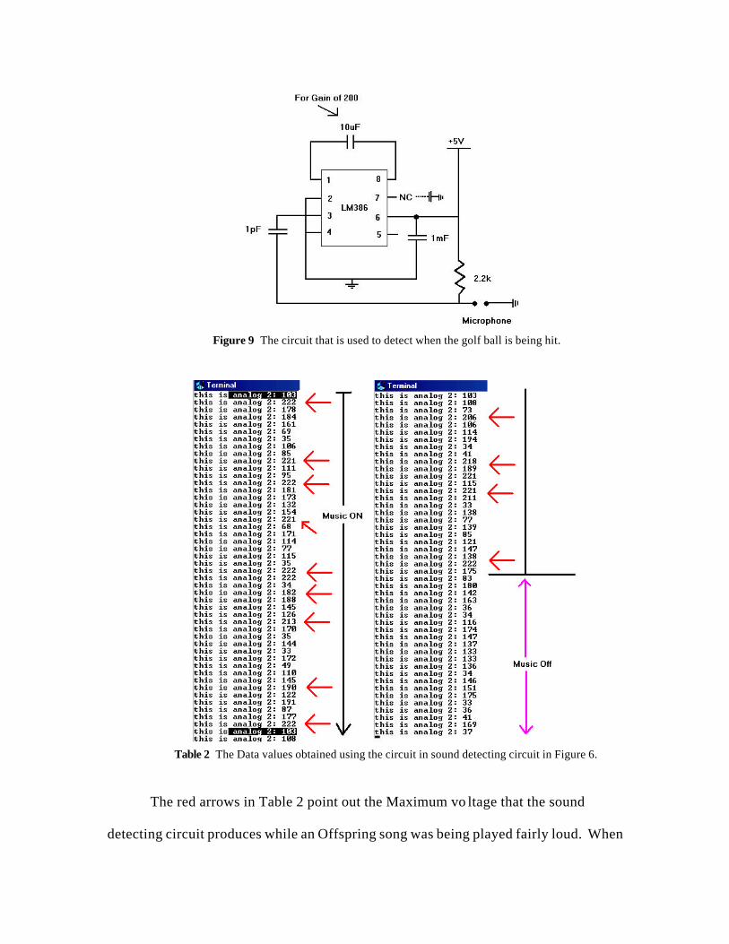
Figure 9 The circuit that is used to detect when the golf ball is being hit.
Table 2 The Data values obtained using the circuit in sound detecting circuit in Figure 6.
The red arrows in Table 2 point out the Maximum vo ltage that the sound
detecting circuit produces while an Offspring song was being played fairly loud. When
the music is off, the voltage stays around 130-175hex with ambiance noise. Sometimes
the voltage goes down to about 30-45hex. When music is being played, or a loud clap (
like a golf ball being hit), the max goes above 190hex, and in most cases easily above
200hex. The microphone will go in the front of the robot and it will indicate that a sound
was detected when the voltage goes above 195hex.
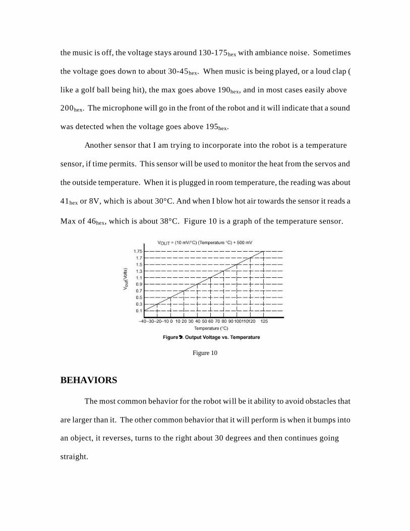
Another sensor that I am trying to incorporate into the robot is a temperature
sensor, if time permits. This sensor will be used to monitor the heat from the servos and
the outside temperature. When it is plugged in room temperature, the reading was about
41hex or 8V, which is about 30°C. And when I blow hot air towards the sensor it reads a
Max of 46hex, which is about 38°C. Figure 10 is a graph of the temperature sensor.
Figure 10
BEHAVIORS
The most common behavior for the robot will be it ability to avoid obstacles that
are larger than it. The other common behavior that it will perform is when it bumps into
an object, it reverses, turns to the right about 30 degrees and then continues going
straight.
The specialized behavior of t he robot will be it ability to find a tee, get close to it
and then place the robot in a precise location so that the arm can be lowered to place a
golf ball atop of the tee. The robot will then back up about 1 foot from the tee. The robot
will then listen for a sound. Before hitting the golf ball the user should place another golf
ball in the bucket again. After hearing what it thinks is a golf ball being hit, the lil
golfing buddy will drive back to the tee to repeat the operation.
EXPERIMENTAL LAYOUT and RESULT
The robot took about 3 months to complete. The code to operate call still be
tweak and improved but the lil Golfing Buddy can avoid obstacles, find a tee, and place a
golf ball on top of the tee.
The lil Golfing Buddy is designed to work in a relative small area with boarders
(for now). In a space about 6 feet by 6 feet and one tee, with walls about half of his
height.
The first behavior that was implemented and works with out any problems is
obstacle avoidance. Using the sharp cans and IR emitting diodes, the lil Golfing Buddy
easily avoids obstacles bigger than a tee and taller than him. I do have video of this,
please see Appendix for more information.
The next thing to be programmed into the obstacle avoidance was the tee finding
behavior. After many version of this code I was finally happy with what is in the
Appendix. I can almost guarantee that the lil Golfing buddy can find the tee within one
minute of the start of the search.
The last part that was programmed was the Y-axis and pitch control. When the
X-axis’s laser beam was broken, the robot would then move the Y-axis’s cds cell down to
create the Y-axis break beam. When that was broken too, the robot would then lift it
back to up to prepare for the lowing of the golf ball. The golf ball is then lowered and
the robot backs up.
This was all accomplished and can be seen on video that I have saved, see
documentation .
CONCULSION
My goal at the start of this project was to create a autonomous intelligent robot
that could place a golf ball on top a tee and I have successfully accomplish it. I have
successfully record on video my robot performing obstacle avoidance and tee finding as
well as a video of placing a golf ball on a tee. When you put the two programs together it
is a little buggy and doesn’t work all the time but it does work. I did not have enough
time to implement the sound part of the design, but that circuit was test and is shown
working in the sensory part of the report.
I am really happy that the lil Golfing Buddy can find the tee under a minute
almost every time. The tee finding code and the obstacle avoidance code works great and
beyond my expectations.
Some things that I would do differently if I was able to start the project over
again. I would use real motors to drive the robot, not the partially modified servos. It
was to hard to make the robot go in a straight path, and it would be easier to control the
lil Golfing Buddy if stepper motors were used instead.

The other major thing I would do is construct a automatic ball re-loader that
would reload the lil Golfing Buddy automatically. The re-loader would either be on the
lil Golfing Buddy itself or a docking station that the lil Golfing Buddy would go in to in
order to get another ball.
And lastly I would build the lil Golfing buddy to stay within a boundary. Instead
of using walls to keep the lil Golfing Buddy in a small area, I would make a boundary
from a wire so that the lil Golfing Buddy would search in a small area enclosed by the
wire.
Many things were learned while building this robot. It takes a lot of hard work
and details to build something like the lil Golfing buddy. This robot made me use things
that I have learned in my first 3 years of college. I really enjoyed this experience and
hope to apply things that I have learned to other classes and my future jobs.
DOCUMENTATION Thanks to IMDL class: Instruction from Dr. Arroyo, Aamir Qaiyumi, Scott Nortman, and Dr. Schwartz. Keith L. Doty.MRC11 Assembly Manual; Mekatronix 1999. Keith L. Doty.MRSX01 Assembly Manual; Mekatronix 1999. Keith L. Doty.Talrik Assembly Manual; Mekatronix 1999. Visit www.mekatronix.com to get the latest version of the Assembly Manuals. Servo City, www.servocity.com. www.onsemi.com for free samples, the 2 input AND chip. Special Thanks to David Offner for his tools, supplies, and help. Also to my parents for funding this adventure. For the latest information please email me at [email protected] or [email protected] . You can also visit the lil Golfing Buddy website at http://members.aol.com/homerj31/lgb/home.html
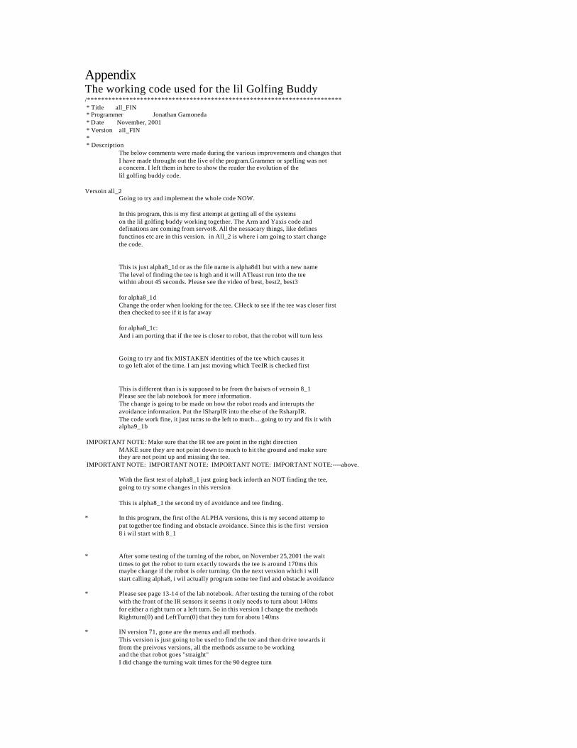
Appendix The working code used for the lil Golfing Buddy /************************************************************************ * Title all_FIN * Programmer Jonathan Gamoneda * Date November, 2001 * Version all_FIN * * Description The below comments were made during the various improvements and changes that I have made throught out the live of the program.Grammer or spelling was not a concern. I left them in here to show the reader the evolution of the lil golfing buddy code. Versoin all_2 Going to try and implement the whole code NOW. In this program, this is my first attempt at getting all of the systems on the lil golfing buddy working together. The Arm and Yaxis code and definations are coming from servot8. All the nessacary things, like defines functinos etc are in this version. in All_2 is where i am going to start change the code. This is just alpha8_1d or as the file name is alpha8d1 but with a new name The level of finding the tee is high and it will ATleast run into the tee within about 45 seconds. Please see the video of best, best2, best3 for alpha8_1d Change the order when looking for the tee. CHeck to see if the tee was closer first then checked to see if it is far away for alpha8_1c: And i am porting that if the tee is closer to robot, that the robot will turn less Going to try and fix MISTAKEN identities of the tee which causes it to go left alot of the time. I am just moving which TeeIR is checked first This is different than is is supposed to be from the baises of versoin 8_1 Please see the lab notebook for more i nformation. The change is going to be made on how the robot reads and interupts the avoidance information. Put the lSharpIR into the else of the RsharpIR. The code work fine, it just turns to the left to much....going to try and fix it with alpha9_1b IMPORTANT NOTE: Make sure that the IR tee are point in the right direction MAKE sure they are not point down to much to hit the ground and make sure they are not point up and missing the tee. IMPORTANT NOTE: IMPORTANT NOTE: IMPORTANT NOTE: IMPORTANT NOTE:----above. With the first test of alpha8_1 just going back inforth an NOT finding the tee, going to try some changes in this version This is alpha8_1 the second try of avoidance and tee finding. * In this program, the first of the ALPHA versions, this is my second attemp to put together tee finding and obstacle avoidance. Since this is the first version 8 i wil start with 8_1 * After some testing of the turning of the robot, on November 25,2001 the wait times to get the robot to turn exactly towards the tee is around 170ms this maybe change if the robot is ofer turning. On the next version which i will start calling alpha8, i wil actually program some tee find and obstacle avoidance * Please see page 13-14 of the lab notebook. After testing the turning of the robot with the front of the IR sensors it seems it only needs to turn about 140ms for either a right turn or a left turn. So in this version I change the methods Rightturn(0) and LeftTurn(0) that they turn for abotu 140ms * IN version 71, gone are the menus and all methods. This version is just going to be used to find the tee and then drive towards it from the preivous versions, all the methods assume to be working and the that robot goes "straight" I did change the turning wait times for the 90 degree turn
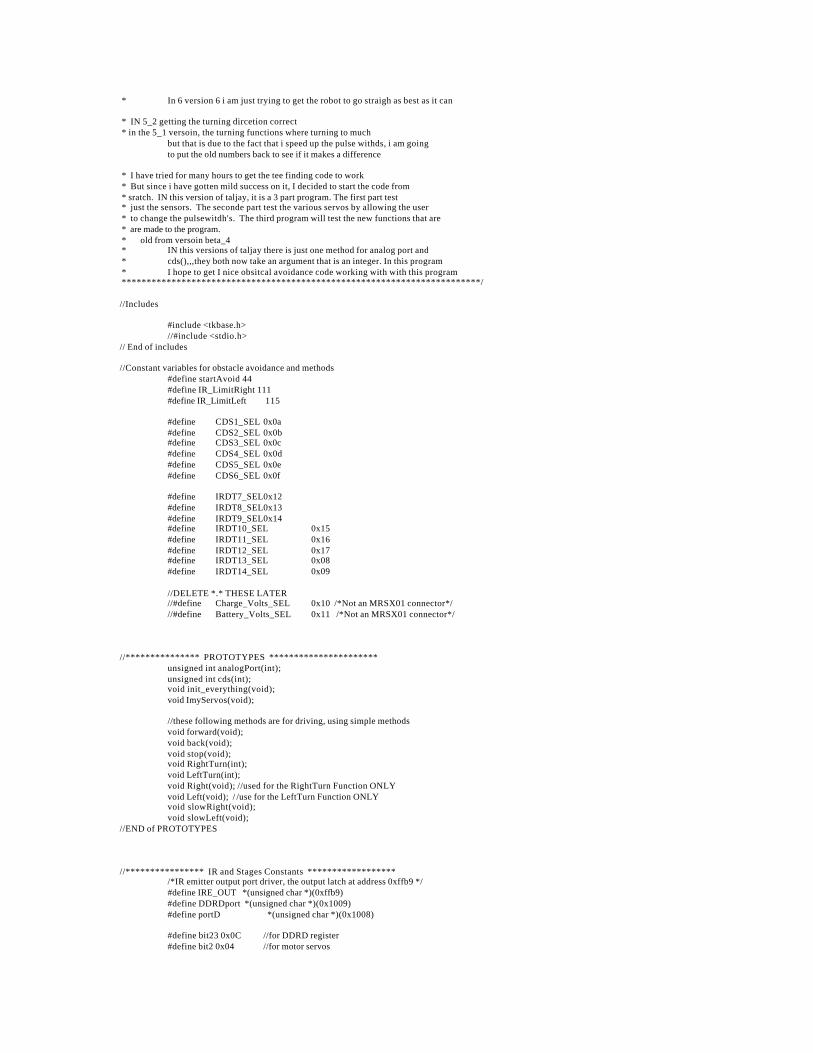
* In 6 version 6 i am just trying to get the robot to go straigh as best as it can * IN 5_2 getting the turning dircetion correct * in the 5_1 versoin, the turning functions where turning to much but that is due to the fact that i speed up the pulse withds, i am going to put the old numbers back to see if it makes a difference * I have tried for many hours to get the tee finding code to work * But since i have gotten mild success on it, I decided to start the code from * sratch. IN this version of taljay, it is a 3 part program. The first part test * just the sensors. The seconde part test the various servos by allowing the user * to change the pulsewitdh's. The third program will test the new functions that are * are made to the program. * old from versoin beta_4 * IN this versions of taljay there is just one method for analog port and * cds(),,,they both now take an argument that is an integer. In this program * I hope to get I nice obsitcal avoidance code working with with this program ************************************************************************/ //Includes #include <tkbase.h> //#include <stdio.h> // End of includes //Constant variables for obstacle avoidance and methods #define startAvoid 44 #define IR_LimitRight 111 #define IR_LimitLeft 115 #define CDS1_SEL 0x0a #define CDS2_SEL 0x0b #define CDS3_SEL 0x0c #define CDS4_SEL 0x0d #define CDS5_SEL 0x0e #define CDS6_SEL 0x0f #define IRDT7_SEL0x12 #define IRDT8_SEL0x13 #define IRDT9_SEL0x14 #define IRDT10_SEL 0x15 #define IRDT11_SEL 0x16 #define IRDT12_SEL 0x17 #define IRDT13_SEL 0x08 #define IRDT14_SEL 0x09 //DELETE *.* THESE LATER //#define Charge_Volts_SEL 0x10 /*Not an MRSX01 connector*/ //#define Battery_Volts_SEL 0x11 /*Not an MRSX01 connector*/ //*************** PROTOTYPES ********************** unsigned int analogPort(int); unsigned int cds(int); void init_everything(void); void ImyServos(void); //these following methods are for driving, using simple methods void forward(void); void back(void); void stop(void); void RightTurn(int); void LeftTurn(int); void Right(void); //used for the RightTurn Function ONLY void Left(void); / /use for the LeftTurn Function ONLY void slowRight(void); void slowLeft(void); //END of PROTOTYPES //**************** IR and Stages Constants ****************** /*IR emitter output port driver, the output latch at address 0xffb9 */ #define IRE_OUT *(unsigned char *)(0xffb9) #define DDRDport *(unsigned char *)(0x1009) #define portD *(unsigned char *)(0x1008) #define bit23 0x0C //for DDRD register #define bit2 0x04 //for motor servos
#define bit3 0x08 //for the positional servos /*Constant for driving all the 40KHz modulated IR emitters on when loaded into IRE_OUT */ #define IRE_ALL_ON 0x0f #define STAGE1_ON 0x2f #define STAGE2_ON 0x4f #define STAGE12_ON 0xCf #define STAGE3_ON 0x8f #define STAGE123_ON 0xEF /*Constant fo r turning all the 40KHz modulated IR emitters off when loaded into IRE_OUT */ #define IRE_ALL_OFF 0x00 #define STAGE1_OFF 0x20 #define STAGE2_OFF 0x40 #define yFirst 0x09F6 // 2520 this is guess as to where the Yaxis' cds cell should go. #define yMax 0x09BA //2490 THIS IS THE ABSOULTE MAX the servo can spin to #define yMin 0x0A3C //2620 the servo should never be near this pulse width //the yAtRest is going to be change to 3500 from 3350 #define yAtRest 0x0DAC //3350 this is where the servo is place when looking for the tee. #define resetArm 0x0AF0 //0x0BB8 //3000 #define finalPitch 0x1068 //0x1004 #define smallStep 0x0A //these last to where changed from varibles to #define step 0x64 //defined // End of Constants // Globals Varibles unsigned int crap, fBumper, lSharpCan, rSharpCan, RteeIR, LteeIR, Xaxis, Yaxis; unsigned int extraIR, extraIR1, extraIR2, extraIR3; int i; /*$$$$$$$$$$$$$$$$$$$$$$$$$$$$$$$$$$$$$$$$$$$$$$$$$$$$$$$$$$$$$$$$$$$$$$$$$ $$$$$$$$$$$$$$ This is the MAIN of the program. $$$$$$$$$$$$$$$ $$$$$$$$$$$$$$$$$$$$$$$$$$$$$$$$$$$$$$$$$$$$$$$$$$$$$$$$$$$$$$$$$$$$$$$$$*/ void main(void) int i, j; //initilize everything init_everything(); //set the positional servos up to get ready to work ImyServos(); /*DO NOT start until the inner Horizontal bumper is pressed*/ while(front_bumper() != startAvoid); IRE_OUT = STAGE1_ON; /* Turns on all the 40KHz modulated IR emitters */ //Get the sensor values rSharpCan = analogPort(2); lSharpCan = analogPort(4); RteeIR = analogPort(12); LteeIR = analogPort(14); fBumper = front_bumper(); Xaxis = cds(5); while(RteeIR < 55 && LteeIR < 50 ) /*If there is no tee, just go foward*/ AGAIN: forward(); rSharpCan = analogPort(2); lSharpCan = analogPort(4); /*check to see if an obstacle is in the way*/ if(lSharpCan > IR_LimitLeft || rSharpCan > IR_LimitRight) //if so then there is something in the way stop(); wait(300); //wait a lil bit before do something /*Now check to see if it was the right or left sharp can*/ if(lSharpCan > IR_LimitLeft) RightTurn(3); RightTurn(2); //this equals about 180 degrees of a turn else if(rSharpCan > IR_LimitRight) //then turn to the left LeftTurn(3);
LeftTurn(2); // LeftTurn(0); //then total turn is about 180 give or take 20 degrees else forward(); else forward(); IRE_OUT = STAGE1_ON; //make sure that STAGE1 LED is on /*Now refresh the values of the teeIR's so the robot continues looking for the lil tee*/ RteeIR = analogPort(12); LteeIR = analogPort(14); /*Now if the robot has found the tee, or it thinks that it has found the tee Then it starts to exacute this part of the program. First it checks to see if the Right teeIR caused the break of the while loop, then the Left tee IR*/ IRE_OUT = STAGE2_ON; //TURN on stage2 LED stop(); RteeIR = analogPort(12); LteeIR = analogPort(14); if(LteeIR > 78)//81 used to be 96 wait(200); Right(); wait(80); stop(); wait(200); forward(); else if(LteeIR >= 44 && LteeIR <= 79)//78 used to be 95 wait(200); RightTurn(0); wait(200); forward(); else if(LteeIR > 78)//81 used to be 96 wait(200); Right(); wait(80); stop(); wait(200); forward(); else if(RteeIR >= 55 && RteeIR <= 79)//used to be 95 //then turn to the left wait(200); LeftTurn(0); wait(200); forward(); else wait(1); goto AGAIN; /*Now that the robot has hopefully turned the right way watch the port that the break beam is on to detect when the robot has located it, but also keep looking for bigger walls*/ while(cds(5) > 200) rSharpCan = analogPort(2); lSharpCan = analogPort(4); /*check to see if an obstacle is in the way*/ if(lSharpCan > IR_LimitLeft || rSharpCan > IR_LimitRight) goto AGAIN;
/*Now if is gets here, then that means that the tee should have broken the Axis Break beam and that the is ready for the next stages of the project To located the exact location of the tee and to place the golfball on the tee*/ stop(); IRE_OUT = STAGE12_ON; //TURN on stage12 LED wait(1000); portD = bit3; //now slowly turn the servo closer to the AT rest point for(i=yAtRest; i > yFirst; i -=smallStep) servo(0, i); wait(25); stop(); wait(200); portD = bit2; //turn on the motor servos //this is new and not tested before using the EXTRA IR extraIR1 = analogPort(3); extraIR2 = analogPort(3); extraIR = (extraIR2 + extraIR1)/2; //if extraIR is great than 77 then the tee is on the right side of the Yaxis and //the robot should turn to the right crap = 0; if(extraIR > 108) if(cds(4) > 180) while(cds(4) > 180 && crap != 3) crap +=1; RightTurn(5); else if(extraIR < 108) if(cds(4) > 180) while(cds(4) > 180 && crap !=3) crap +=1; LeftTurn(5); wait(1000); //I HOPE THE ABOVE CODE WORKS if(cds(5) < 200 && cds(4) < 180) IRE_OUT = IRE_ALL_OFF; else IRE_OUT = STAGE123_ON; ImyServos();//to make sure if the ball does not get on the Tee, it won't break my yaxis wait(1000); stop(); portD = bit3; //make sure Arm sevor is selected //this slowly lowers the arm to place the golfball on the tee for(j=resetArm; j < finalPitch; j +=step) servo(1, j); wait(300); stop(); wait(300); portD = bit2; //select the motor servos.
back(); wait(1000); ImyServos(); //this is where the sound detecting code will go. //End of Main ******************************/ /************************************************************************ ************************************************************************* ************ THE START OF MY METHODS ************************* ************************************************************************* ************************************************************************/ /* The analogport() is a methods that the end user can call from the main program that will allow the end user to obtained the analog value from any Analog port on the MSRX11 board It takes the place of read_IR. You can pass numbers from 1 -14 in it*/ unsigned int analogPort(int get) if(get<=6) //NOTE: this method does not check for bad inputs return analog(get + 1); if(get==7)mux_sensor(IRDT7_SEL); return analog(0); if(get==8)mux_sensor(IRDT8_SEL); return analog(0); if(get==9)mux_sensor(IRDT9_SEL); return analog(0); if(get==10)mux_sensor(IRDT10_SEL); return analog(0); if(get==11)mux_sensor(IRDT11_SEL); return analog(0); if(get==12)mux_sensor(IRDT12_SEL); return analog(0); if(get==13)mux_sensor(IRDT13_SEL); return analog(0); if(get==14)mux_sensor(IRDT14_SEL); return analog(0); else return 0; //This mehtod takes an integer from 1 to 6 to select the correct //port of the cds to be read, and then returns the analog value of //the voltage divider circuit of a cds and 1 resistor (either 1k or 10k) unsigned int cds(int num) if(num==1)mux_sensor(CDS1_SEL); return analog(0); if(num==2)mux_sensor(CDS2_SEL); return analog(0); if(num==3)mux_sensor(CDS3_SEL); return analog(0); if(num==4)mux_sensor(CDS4_SEL); return analog(0); if(num==5)mux_sensor(CDS5_SEL); return analog(0); if(num==6)mux_sensor(CDS6_SEL); return analog(0); else return 0; //end of cds method /*Use this function to turn right. It takes an arugment that is an int If degree = 0 , tfor tee turn If degree = 1 , then the turn is about 20-30 If degree = 2 , then the turn is about 45 If degree = 3 , then the turn is about 90*/ void RightTurn(int degree) //for a 10-20 degree turn if(degree == 0) Right(); wait(145);//this number used to be 170 stop(); wait(1); //for a 20-30 degree turn if(degree == 1) Right(); wait(185); stop(); wait(1); //for a 45degree turn if(degree == 2)
Right(); wait(370); stop(); wait(1); //for a 90 degree turn if(degree == 3) Right(); wait(720); stop(); wait(1); //for a 180 degree turn if(degree == 4) Right(); wait(1460); stop(); wait(1); if(degree == 5) Right(); wait(80); stop(); wait(1000); /*Use this function to turn Left. It takes an arugment that is an int If degree = 0 , for Tee turn If degree = 1 , then the turn is about 20-30 If degree = 2 , then the turn is about 45 If degree = 3 , then the turn is about 90*/ void LeftTurn(int degree) //for a 10-20 degree turn if(degree == 0) Left(); wait(145); //this number used to be 170 stop(); wait(1); //for a 20-30 degree turn if(degree == 1) Left(); wait(185); stop(); wait(1); //for a 45degree turn if(degree == 2) Left(); wait(370); stop(); wait(1); //for a 90 degree turn if(degree == 3) Left(); wait(690); stop(); wait(1); //for a 180 degree turn if(degree == 4) Left(); wait(1460); stop(); wait(1); if(degree == 5) Left();
wait(80); stop(); wait(1000); //this is the right turn function that makes the robot motors go // in opposite directions turning the robot t o the left void Left(void) servo(0, 4430); //left motor servo(1, 4430); //right motor //This function makes the motors turn oppsite directions making the //robot turn to the right void Right(void) servo(0, 1530); //left motor servo(1, 1530); //right motor //Use this function to make the robot go forward void forward(void) servo(0, 2400); //left motor,,,used to be 1650 servo(1, 4900); //right motor //Use this function to make the robot go back void back(void) servo(0, 1200); //left motor servo(1, 4800); //right motor //When this function is called, the both servos on the lil golfing //buddy will stop void stop(void) servo(0, 0); //left motor servo(1, 0); //right motor //This fucntiong initinlizes everything. Please see contents of the function void init_everything() //initilize everything init_analog(); init_motortk(); init_clocktk(); init_serial(); init_servos(); IRE_OUT = STAGE1_OFF; void ImyServos(void) DDRDport = bit23; portD = bit3; //for yaxis use left servo control servo(0, yAtRest);//yAtRest //for arm pitch use right servo control servo(1, resetArm);//resetArm wait(1000); stop(); //just added in all_2 portD = bit2; //these last to functions are used to located the EXACT locations of the TEE void slowLeft(void) servo(0, 3100); //left motor servo(1, 3100); //right motor //This function makes the motors turn oppsite directions making the //robot turn to the right void slowRight(void) servo(0, 2850); //left motor servo(1, 2850); //right motor
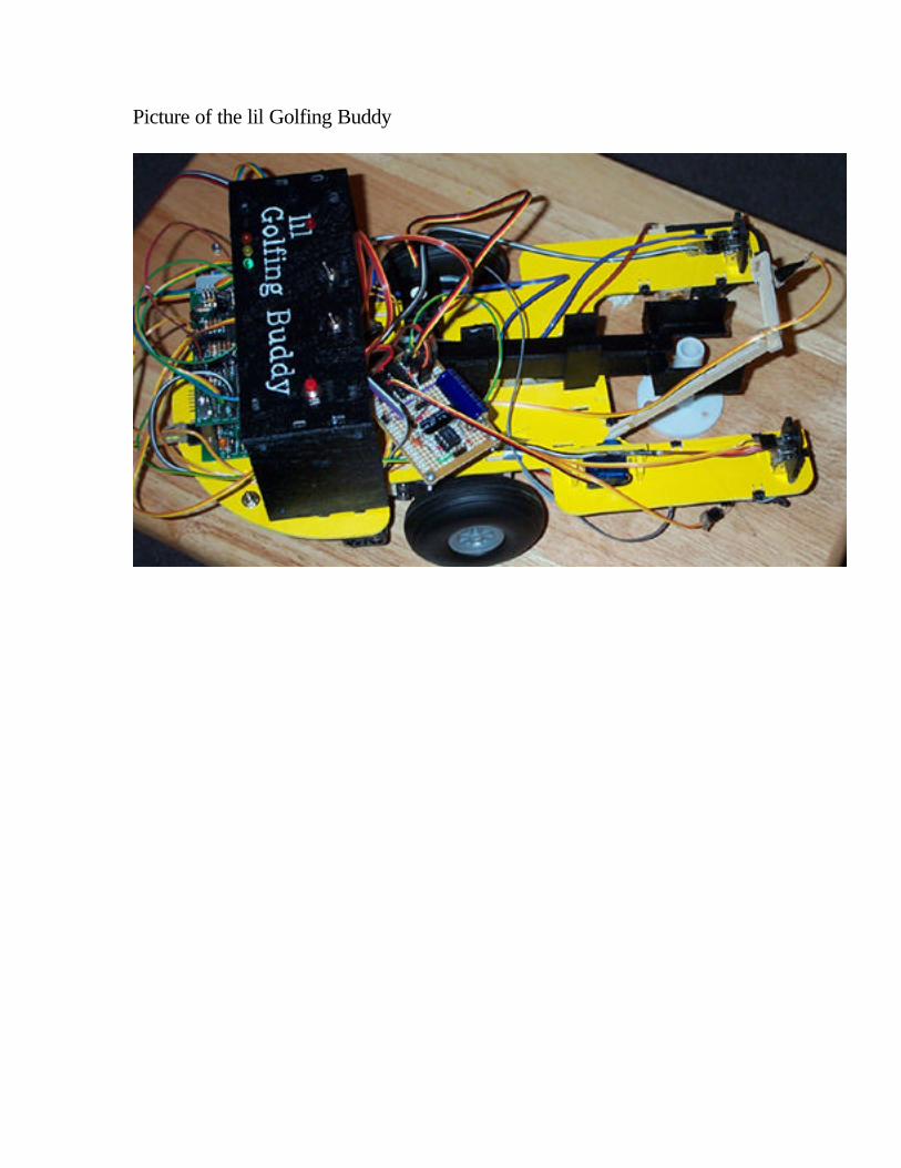
Picture of the lil Golfing Buddy