1 - machine intelligence lab€¦ · web view2006-04-24 · university of florida. department of...
TRANSCRIPT

Ferrarobot
University of FloridaDepartment of Electrical and Computer Engineering
EEL 5666Intelligent Machines Design Laboratory
Kyle L. Carithers4/25/06
TAs: Adam Barnett
Sara Keen
Instructors:Dr. SchwartzDr. Arroyo

Table of Contents
Title Page…………………………………………... 1
Table of Contents………………………….............. 2
Executive Summary………………………………. 3
Abstract……………………………………………..4
Introduction…………………………………………5
Mobile Platform…………………………………….5
Actuation……………………………………………6
Sensors……………………………………………... 7
Mechanical devices……………………………….. 8
Conclusion…………………………………………. 13
2

Abstract
Ferrarobot is a high speed line, following robot with a car-like design that simulates drag racing. This robot is fairly simple from an electrical standpoint. The electronics consist mainly of obstacle avoidance and line following sensors and a mavric IIb board. Ferrarobot features car like mechanical systems that improve performance. These include a rack and pinion steering column and a rear differential that allows a single motor to drive both rear wheels.
3

Executive Summary
Ferrarobot was constructed over the spring 2006 for IMDL. The original intent of
my efforts was to build a car like vehicle that could demonstrate object following to
simulate driving typical of law enforcement. When it became apparent that incorporating
a vision system into the design would not be possible, primarily due to time constraints,
the robot evolved. The compact, car like platform was quick. Drag racing would be an
ideal task for the robot and the name Ferrarobot was coined.
Ferrarobot is a relatively simple robot that incorporates complex mechanical
components into a compact design. The robot is programmed to follow a straight line
with its speed based on patterns detected by the line tracking sensor. The robot responds
to one of the patterns by accelerating to top speed until the end of the track. The other
patterns cause the robot to change speeds throughout the race.
4

Introduction
Ferrarobot will use its car-like platform to follow a straight line at high speeds. This
robot is fast, well, fast compared to a typical robot driven by hacked servos. The robot
uses a line tracking sensor from Lynxmotion to follow the straightaway. The robot uses
IR proximity detecting sensors also by Lynxmotion, along with simple bump switches for
obstacle avoidance.
Mobile Platform
The robot mechanics consists of three main components: the frame, the steering system,
and the drive train. The frame consists of two platforms, separated by two inch long
standoffs. These platforms were machined from a quarter inch thick polycarbonate
material.
The lower platform houses the mechanical components of the robot. The steering
system and the drive system will bolt directly onto the platform. The motor, battery,
servo and various other electronics will also be located on this platform.
The steering system consists of a Lego rack and pinion gearing that attaches
directly to the wheels. A servo will control the angle of rotation. The gearing system
will bolt directly onto the lower platform. The drive train will consist of a Lego rear axle
powered by a single motor. The motor and axle will be supported by a piece that will
connect it to the frame. The rear axle features a Lego differential that allows the tires to
rotate in opposite directions while the gear connected to the motor remains fixed. The
frame will bridge together the steering and drive train components while also acting as a
platform for the circuitry and sensors. Lego wheels and tires will be used on the robot.
5

The microcontroller, motor driver, etc. will attach to the upper platform.
Actuation
The robot will use one servo and one motor. The servo is a Hitec model chosen because
an expensive servo was not required. The servo will attach to a Lego axle using a shaft
adaptor. The axle will attach to the pinion.
The motor is a Jameco gear head model with a 10 to 1 ratio, max torque of 350 g-cm, and
a speed of 600 rpm.
6

Sensors
The robot I have constructed uses the following sensors and mechanical components:
IR Proximity Detector Sensor and Tracker Sensor by Lynxmotion
Click Action Basic Precision Switch from Jameco
Rack and Pinion steering column by Lego
7

Differential gear by Lego
Mechanical devices
The typical setup used in constructing most robots in this class includes two
wheels with a motor attached to each. The two wheels both power and steer. The robot
of course turns by applying a greater voltage to one motor or the other. This system does
have some drawbacks. The main drawback to this system is that two motors will likely
8
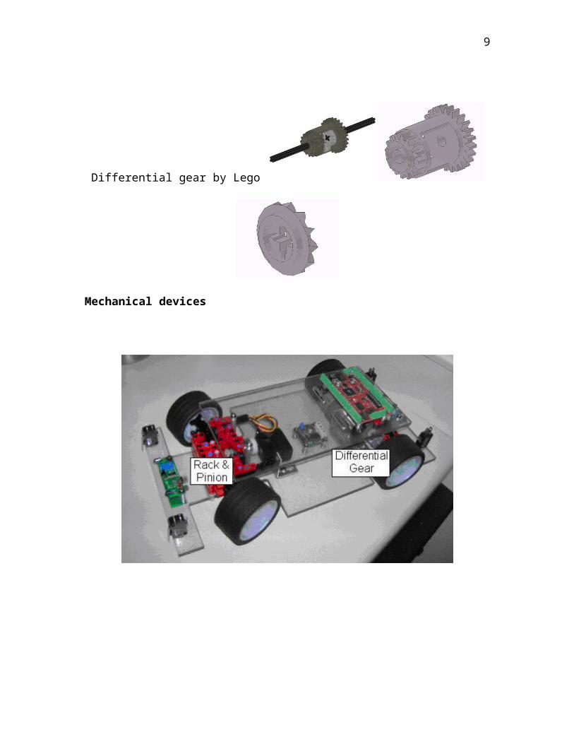
supply at least slightly different voltages. A robot in this setup will experience difficulty
driving straight. In most cases, the robot will have to use a third roller or swivel wheel.
The size of the robot is limited in this setup because of the torque required to overcome
the friction involved.
For the robot I constructed, I chose to build the robot to simulate car-like driving.
This involves rack and pinion steering and rear wheel drive powered by a single motor.
The benefit of this setup is that the robot should have little problem traveling straight.
There is a single motor that applies an even amount of torque to each wheel. A larger
robot can be constructed that does not require a high friction third wheel. The rear
wheels can focus on driving while the front wheels can focus on steering.
One of the major disadvantages of this system is that steering becomes much
more complicated. The front steering wheels now have to rotate together. The
complicated nature of this type of steering is a major reason for why I chose to
incorporate Lego products into my design. Another disadvantage is that with this setup,
the robot has a turning radius. In the two wheel setup, if the robot must go to a specific
object forward and to the left, the robot can stop, turn towards the point, and then move in
a generally straight direction. In the front wheel drive setup, it must go forward and left
at the same time. Programming the robot becomes more difficult as it must account for
this turning radius.
9

Steering Column
I built the rack and pinion steering system from Lego pieces in such a way that it
could be bolted directly to the polycarbonate platform eliminating the need for any type
of connecting piece. A Lego shaft connects the servo to the pinion gear. The pinion gear
meshes with the rack gear. When the servo rotates, the pinion rotates and the rotation is
converted into translation of the rack. The rack is connected to each wheel hub by a rod.
Each hub is mounted by a ball and socket joint and rotates with translation of the rack.
Pinion Gear Rack Gear
10

Differential Gear
Using a single motor has clear benefits. In most cases though, using one motor
requires using a single, connected axle. A problem arises when wheels must rotate at
different speeds, which would occur any time the robot is turning. A single axle of
course does not allow for wheels at each end to rotate at different speeds. If a turn is
attempted, then slip must occur, meaning a tire would slide against the road or other
surface. When dealing with larger robots or vehicles, more weight and friction is
involved. This makes slipping harder because it requires a greater force and makes
turning much more difficult because turning in this case requires slipping in the rear
wheels.
To allow each wheel to rotate at a different spend, avoid slipping, and improving
the ease of turning a differential is used. The differential applies an equal amount of
torque to each wheel but allows for the wheels to rotate at different speeds. The best way
to explain how this is done is by showing the system under various conditions.
11

In the above picture, from Wikipedia, both wheels would be turning. Assuming that a
motor applies torque to the blue gear and that the red and yellow gears rotate at the same
velocity, the green gear would apply an equal torque to both the red and yellow gears.
This could occur when the robot is traveling either forwards or backwards.
In the above picture, also from Wikipedia, the wheel attached to the yellow gear would
be turning. Assuming that a motor applies torque to the blue gear and that the red and
yellow gears rotate at the same velocity, the green gear would apply an equal torque to
both the red and yellow gears. This could occur when the robot is turning, although there
would likely be some rotation of the red gear.
12

Conclusion
In summary, Ferrarobot demonstrates obstacle avoidance and staight line tracking
at relatively high speeds. Ferrarobot simulates car like behavior in the form of a drag
racing robot.
The speed, though relatively quick, could be greatly improved by decreasing
weight. I was not as focused on weight as I was on building a functioning robot. My
robot was designed to eliminate risk and improve efficiency. In this case I mean
efficiency in terms of my time. This class is incredibly demanding, and is a high risk
class, particularly if you are not a computer or electrical engineer. What I mean is that if
you take this class, you could spend all of your time on this class, fail your other classes,
and still not have a functioning robot. That may be extreme but it is possible. I spent a
lot of time on the robot and still didn’t have a functioning robot until the end.
I recommend that you consider time in your planning. I also recommend
choosing a design that is small and compact. If you have an idea for a robot that includes
a massive design, make a smaller robot and apply the concepts to the larger design later.
In most cases, a small robot can demonstrate most of what a larger robot can.
Going back to weight, I machined a piece of polycarbonate (MSCDirect.com) to
form the robots platform. I would highly recommend polycarbonate. Have a piece
cutout to your specifications from a company that can cut it. I would recommend
avoiding spending time in the machine shops unless completely necessary. A company
can cut for less than what you could earn at a part time job. If that’s not an option,
polycarbonate is still a great choice as it can be drilled using tools designed for wood. I
13

could have cutout areas in the polycarbonate to decrease the weight but I didn’t know for
sure that the areas would be unused.
I also didn’t use my power supply as effectively as I could. I originally planned
to use two 7.2 V supplies, one for the mavric and one for motor/servo power. I had
planned on using the Vcc out from the motor controller to power the servo but it didn’t
supply enough amps. Instead of building a power board and incorporating a regulator, I
just bought some AAs and used them to power the servo. This added weight.
If you haven’t considered using Lego components, I recommend considering it.
Building a steering column and differential from scratch would have been close to
impossible. Avoid the brick type Legos though, and recognize that Legos are meant to be
taken apart and don’t provide much support.
I would like to incorporate a vision system into this robot. I plan on doing so
with this or a similar robot and developing code so that it can follow another vehicle or
object.
14

Appendix
Appendix A
New to robotics? Read this.
I spent way too much time trying to figure out where to even begin. I will attempt
to summarize what you need to do to get started.
1. Figure out what board you will use. Actually, if you are reading this, go buy a mavric
IIb from www.bdmicro.com without the screw terminals. It’s a great board and most of
the people in this class will use it. You will need a power supply for the board to do
anything with it. Just grab an old wall wart that supplies at least 5Vs and cutoff and split
the end.
2. Next, you need a compiler that can compile for an atmega128. Programmers notepad
from Winavr is great (and free), search avrfreaks.net. Then download Ponyprog, (also
free) a program that can send code to you board.
3. You also need to order a programming cable. Its actually more of a converter than a
cable. There is ISP and Jtag, most of us use ISP. You can order one from Sparkfun. I
believe they have serial and parallel, either way, order a serial or parallel cable along with
it. The dumbest thing I did all semester was order a serial cable thinking I could plug it
into the vga output on my laptop, so don’t do that.
This should all be done ASAP, if you haven’t done this by the second week you
are behind. To compile something, you need a makefile in the same folder as the code.
When compiled, a hex file is created. Use the hex file in ponyprog to send the code to
your board. Bdmicro has a nice blinking light program to get you started.
Finally, learn to love the atmega128 datasheet, all 300 pages of it.
15

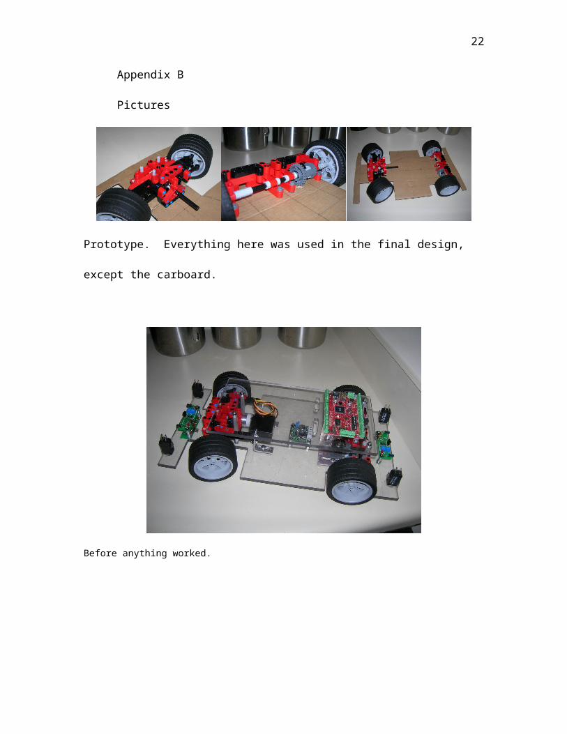
Appendix B
Pictures
Prototype. Everything here was used in the final design, except the carboard.
Before anything worked.
Final design. Notice the aluminum front and rear bumper, the doors, and the heavy unplanned battery pack
on top.
16

Appendix C
Code
#include <avr/io.h>#include <avr/pgmspace.h>#include <stdio.h>#include <avr/interrupt.h>
#define SERVO1 OCR3A#define SERVO3 OCR3C
#define SERVO_MIN 2000#define SERVO_MID 2975#define SERVO_MAX 4000
#define speed_dif 25 //75 for fast acc//50 for highspeed, 25 for HIWAA//
#define magnitude_increase 5
volatile uint16_t ms_count;
volatile brake_dif;
/*Count is added to each time timer2 triggers the interrupts, when count = 100, functions are called that check the sensors.Front_obstacle and rear_obstacle signal whether or not there is an obstacle.L, C, and R report whether or not the line tracking sensors detects anything on the left, center and right sensors. Timer2 */
int count;int front_obstacle;int rear_obstacle;
int L;int C;int R;
int line; //line=1 when atleast 1 sensor detects the line//
int L_counter; int L_magnitude;int C_counter;int R_counter; int R_magnitude;
int mode; // 1 for dragracing(000, all black), 2 for
//operational_status is set to current operation. 0=searching for a line, 1=searching for drag strip, 2=racing drag strip//int operational_status;
void ms_sleep(uint16_t ms){
TCNT0 = 0;ms_count = 0;
17

while (ms_count != ms);}
SIGNAL(SIG_OUTPUT_COMPARE0){ ms_count++;}
void init_timer(void){ TIFR |= _BV(OCIE0); TCCR0 = _BV(WGM01)|_BV(CS02)|_BV(CS00); TCNT0 = 0; TIMSK |= _BV(OCIE0); OCR0 = 125;
}
SIGNAL(SIG_OVERFLOW3){ TCNT3 = 0; TCCR3A |= _BV(COM3A1)|_BV(COM3A0)|_BV(COM3B1)|_BV(COM3B0)|_BV(COM3C1)|_BV(COM3C0); TCCR3C |= _BV(FOC3A)|_BV(FOC3B)|_BV(FOC3C); TCCR3A &= ~(_BV(COM3A0)|_BV(COM3B0)|_BV(COM3C0));
}
void init_timer2(void){
count=0;TIFR |= _BV(OCIE2);TCCR2 |= _BV(CS21);TCNT2=0;OCR2=200;TIMSK |=_BV(OCIE2);}
SIGNAL(SIG_OUTPUT_COMPARE2){
count=count+1;
if (count==20){
check_for_obstacle();}
if (count==40){
status_right ();}
if (count==60){
status_center ();}
if (count==80){
18

status_left ();if((L==1) || (C==1) || (R==1)) {line=1;}
}
if (count==100){
//set servo3//if((operational_status==2) && (line)){
if((L==0)) //robot is left of the line//correct/{ //SERVO3=3350-L_magnitude;
if((SERVO1>3050) & (SERVO1<=3250)){SERVO3=3450-L_magnitude;}
if((SERVO1>3250) & (SERVO1<=3500)){SERVO3=3350-L_magnitude;}
if((SERVO1>3500)){SERVO3=3250-L_magnitude;}//SERVO3=(2850+(SERVO1-2975);
}if((R==0)) //robot is right of the line//
{//SERVO3=2350+R_magnitude;if((SERVO1>3050) & (SERVO1<=3250))
{SERVO3=2250+R_magnitude;}if((SERVO1>3250) & (SERVO1<=3500))
{SERVO3=2350+R_magnitude;}if((SERVO1>3500))
{SERVO3=2450+R_magnitude;}}
}count=0;
}
TCNT2 = 0;}
void init_servos(void){
DDRE |= _BV(PORTE3) | _BV(PORTE4) | _BV(PORTE5); TCCR3A &= ~(_BV(WGM31) | _BV(WGM30) | _BV(COM3A1) | _BV(COM3B1) | _BV(COM3C1)); TCCR3A |= _BV(COM3A0) | _BV(COM3B0) | _BV(COM3C0); TCCR3B &= ~(_BV(WGM33) | _BV(WGM32) | _BV(CS32) | _BV(CS30)); TCCR3B |= _BV(CS31); TCNT3 = 0; TCCR3C |= _BV(FOC3A) | _BV(FOC3B) | _BV(FOC3C); ETIMSK |= _BV(TOIE3);
SERVO1 = SERVO_MID;SERVO3 = SERVO_MID;
}
//velocity functions will be used to change from current speed to desired speed.//Int speed represents the current speed in the main function.//Neutral between 2950 and 3000, moves forward at 3050.
void increase_velocity (int speed_i, int speed_f){
19

int n=speed_i;while(n<speed_f && !front_obstacle){
n=n+speed_dif;SERVO1=n;PORTB = 0x01; ms_sleep(50); PORTB = 0x00; ms_sleep(50);
}}
void decrease_velocity (int speed_i, int speed_f){
int n=speed_i;while(n>speed_f && !rear_obstacle){
n=n-speed_dif;SERVO1=n;PORTB = 0x01; ms_sleep(50); PORTB = 0x00; ms_sleep(50);
}}
int BRAKE (int speed_i){
int n=speed_i;int brake_dif=5;
if (speed_i>SERVO_MID){
if(speed_i>3250) brake_dif=5;if(speed_i>3500) brake_dif=10;if(speed_i>3750) brake_dif=25;if(speed_i>4000) brake_dif=45;
while(!(n>SERVO_MID-75 && n<SERVO_MID+25)){
n=n-speed_dif;SERVO1=n;PORTB = 0x01; ms_sleep(1); PORTB = 0x00; ms_sleep(2);
}}
if (speed_i<SERVO_MID){
if(speed_i<2500) brake_dif=100;if(speed_i>2000) brake_dif=200;
while(!(n>SERVO_MID-25 && n<SERVO_MID+75)){
n=n+speed_dif;SERVO1=n;PORTB = 0x01; ms_sleep(1); PORTB = 0x00; ms_sleep(19);
}}
SERVO1=SERVO_MID;}
20

void move(int desired_speed){
while ((!front_obstacle) && (!rear_obstacle)){if (desired_speed>SERVO1) increase_velocity(SERVO1,desired_speed); if (desired_speed<SERVO1) decrease_velocity(SERVO1,desired_speed);}
}
////////////////////////////////////////////////////////////////////////////////////////////////////////////////////////////////////////////////////////////
int status_left (void){
int i=0;int n=0;L=0;
{while(i<=10){
i=i+1;if (!(PING & 0b000000001))
{ n=n+1;}}if (n>=5) {
L=1; //L_counter=L_counter+1; L_magnitude=0;}
if (n<5){
L=0; //L_counter=0;if(L_magnitude<=500)
{L_magnitude=L_magnitude+magnitude_increase;}}
}
//L_magnitude=multiply(L_counter, 20);return (L);
}
int status_center (void){
int i=0;int n=0;C=0;
{
21
while(i<=10){
i=i+1;if (!(PING & 0b00000010))
{ n=n+1;}}if (n>=5) {C=1; C_counter=C_counter+1;}if (n<5) {C=0; C_counter=0;}
}
return (C);}
int status_right (void){
int i=0;int n=0;R=0;
{while(i<=10){
i=i+1;if (!(PING & 0b00000100))
{ n=n+1;}}if (n>=5) {
R=1; //R_counter=R_counter+1;} R_magnitude=0;
}
if (n<5) {
R=0; //R_counter=0;if(R_magnitude<500)
{R_magnitude=R_magnitude+magnitude_increase;}}
}//R_magnitude=multiply(R_counter, 20);return (R);
}
int check_for_obstacle (void){int i=0;int n=0;front_obstacle=0;rear_obstacle=0;
if(SERVO1>=3025){
while(i<=10){
22

i=i+1;if (!(PINC & 0b00000001) || (PINC & 0b00000100) || (PINC & 0b00001000))
n=n+1;}if (n>=5) {front_obstacle=1;} if (n<5) {front_obstacle=0;}
}if(SERVO1<=2925){
while(i<=10){
i=i+1;if (!(PINC & 0b00000010) || (PINC & 0b000010000) || (PINC & 0b000100000))
n=n+1;}if (n>=5) {rear_obstacle=1;} if (n<5) {rear_obstacle=0;}
}if ((SERVO1<3025) && (SERVO1>2925)) { front_obstacle=0; rear_obstacle=0;}
return ((front_obstacle) || (rear_obstacle));}/////////////////////////////////////////////////////////////////////////////////////////////////////////////////////////////////////////////////////////
int multiply(int number, int mult_by){int i=0;
while(i<mult_by){number=number+number; i=i+1;}
return(number);}
void obstacle_avoidance (void){
move(3750);BRAKE(SERVO1);SERVO3=2250;move(2500);BRAKE(SERVO1);SERVO3=3750;move(3500);SERVO3=2850;BRAKE(SERVO1);
}
void coast(int time){
int i=0;while((!front_obstacle) && (!rear_obstacle) && (i<time))
{ms_sleep(50); i=i+50;}}
int main(void){ init_timer(); init_servos();
23

init_timer2(); sei(); DDRB = 0x01; DDRG = 0x00; DDRC = 0x00; DDRA = 0xFF; PORTA = 0xFF; DDRF = 0xFF; PORTF = 0xFF;
ms_sleep(512);PORTB = 0x01; ms_sleep(512); PORTB = 0x00; ms_sleep(512);
operational_status=0;
while(1){
while ((PINC & 0b000010000) || (PINC & 0b000100000)){//check pattern//status_left(); status_center(); status_right(); if((L==0) && (R==0) && (R==0)){mode=1;}//000 for drag raceif((L==1) && (C==0) && (R==1)){mode=2;}//101if((L==0) && (C==1) && (R==0)){mode=3;}//010if((L==1) && (C==1) && (R==1)){mode=4;}//111 for HIWAA
ms_sleep(512);PORTB = 0x01; ms_sleep(512); PORTB = 0x00; ms_sleep(512);
L_magnitude=0;R_magnitude=0;
move(3200);operational_status=2;
if(mode==1){move(4200);}
if(mode==2){
while((!front_obstacle) && (!rear_obstacle)){
move(3600); coast(3000) ;move(3300); coast(3000);move(4200); coast(3000);move(3500); coast(3000);
}}
if(mode==3){
while((!front_obstacle) && (!rear_obstacle)){
move(3300); coast(3000) ;move(3700); coast(3000);move(3200); coast(3000);
24

move(4200); coast(3000);}
}
if(mode==4){move(3400);}
}
}}
25