fault ride through during loss of converter in a 4-vsc ... ride through during loss of converter in...
TRANSCRIPT

Fault Ride Through during loss of converter in a 4-VSC based HVDC transmission
Olusegun Olowookere, Spyros Skarvelis-Kazakos, Yehdego Habtay and Steve Woodhead Faculty of Engineering and Science
University of Greenwich Medway,UK
Abstract— VSC based Multi-terminal HVDC transmission is employed for the integration of offshore wind and wave farms. Flexibility, reliability and reduced transmission losses are the main/primary reasons for preference of MTDC networks. The transmission layout still suffers from some drawbacks, of which the most prominent is fault ride through capability in terms of its response to either a temporal or permanent loss of converter station(s). This paper presents the simulation analysis of hysteresis based and PI- based DC grid voltage control techniques for fault ride through capability of a 4 terminal HVDC network (MTDC), which consisted of a wind farm, wave farm and two onshore converters. The analysis showed that the PI method resulted in a faster response time as well as smaller overshoots and dips when a three phase to ground fault occurs. A detailed electromagnetic transient (EMT) study was performed using MATLAB/Simulink.
Index Terms-- Fault ride through (FRT), Hysteresis controller, PI controller, VSC HVDC, MTDC.
I. INTRODUCTION Large offshore wind farms have been developed to
actualize the UK’s target of developing 25GW installed generation capacity in accordance with Round 3 programme. For large offshore farms, there is a need for effective and efficient integration due to the fact that most of the farms are located in remote areas with long distances between one another. Integration issues will involve onshore connection in terms of economic, technical and environmental consideration by operators [1].
Wind turbine based technologies employed for grid integration include the use of: squirrel cage induction generators (for fixed speed applications) [2], [3], doubly fed induction generators (for variable speed and partially rated power electronic converters) [4], [5], and synchronous generators (for variable speed and fully rated power electronics converters) [6]. The generator technologies of wind turbines are also applied to wave converter technologies.
HVDC transmission has been accepted as the preferred technology for connecting wind farms in large remote areas [7]. The HVDC technology types include: line commutated converters (LCC), voltage source converters (VSC), and
hybrid [8]. VSCs have been normally considered for the integration of wind farms due to their superiority to the LCCs in terms of: independent four quadrant power control, black start capability, excellent AC fault response, lack of commutation, asynchronous systems connection and lack of reactive power compensation [9], [10].
The need for satisfactory fault ride through capability of HVDC connected wind/wave farms cannot be overemphasized and this has been studied mainly for back to back HVDC linking of wind farms. However, due to large combined offshore transmission layout in which many wind farms and wave farms are incorporated, the multi-terminal HVDC network has become the preferred choice, especially, for power transmission between generator- based wind and wave farms and AC networks [11].
There is a DC fault in a multi-terminal HVDC network when there is a loss of a converter station, and this can also lead to transient DC overvoltage due to system response delay [12]. For a simple 4-terminal HVDC network, there are different control strategies employed to maintain DC voltage and active power balance within acceptable ranges [13]:
a) Master -Slave- where one converter station serves as the slack bus for the control of the DC voltage and other converter stations control the active power.
b) Coordinated droop control- where two or more converter stations control DC voltage in droop terms and the other stations control the active power.
c) Master- Slave with droop control- where one station controls the DC control in constant term and other stations control DC voltage in droop terms.
Therefore, not only are fault-ride through strategies necessary, so also, are the employed FRT controllers. Overall, the DC voltage variations issue is the major concern for MTDC network design and operation. The major contribution of this paper is a comparison of two controllers: PI based and hysteresis voltage modulation based schemes for DC resistor dumping action for AC fault ride through capability of four terminal HVDC systems.
The remainder of the paper is organized as follows: Section II covers combined offshore wind and wave farm
1
978-1-4799-7720-8/14/$31.00 ©2014 IEEE
2014 5th IEEE PES Innovative Smart Grid Technologies Europe (ISGT Europe), October 12-15, Istanbul
VSC-HVDC system configuration. Section III discusses active power and DC voltage control. Section IV discusses AC fault ride through methodology. Section V deals with analysis of FRT controllers. Section VI discusses past work on PI and Hysteresis controllers. Section VII discusses the simulation parameters selection, assumptions and simulated results. Finally, section VIII presents some conclusions.
II. COMBINED OFFSHORE WIND AND WAVE FARM VSC- HVDC SYSTEM CONFIGURATION
The location of independent offshore wind farms has a major part to play in the actualization of a reliable and optimum MTDC system. Most offshore wind farms are interconnected through undersea cables (submarine) to the AC connection points at the onshore sides. In [15], a 4- terminal arrangement was employed for the interconnection of two wind farms to the onshore AC grid. This arrangement has been utilized for the interconnection of combined offshore wind and wave farms. Other DC configurations exists which will require different control means.
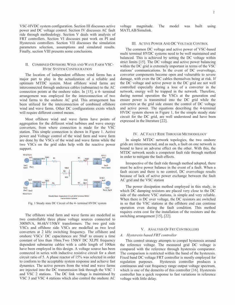
Most offshore wind and wave farms have points of aggregation for the different wind turbines and wave energy converters, from where connection is made for the VSC station. This simple connection is shown in Figure 1. Active power and Voltage control of the wind farm and wave farm are done by the VSCs of the wind and wave farms while the two VSCs on the grid sides help with the reactive power support.
Fig. 1 Steady state DC Circuit of the 4- terminal HVDC system
The offshore wind farm and wave farms are modelled as two controllable three phase voltage sources connected to 300MVA, 86.6kV/150kV transformers. The two gird side VSCs and offshore side VSCs are modelled as two level converters at 2 kHz switching frequency. The offshore and onshore VSCs’ DC capacitances are 50uF to ensure a time constant of less than 10ms.Two 150kV DC XLPE frequency dependent submarine cables with a cable length of 100km have been employed in this design. A voltage source has been connected in series with inductive resistive circuit for a short circuit ratio of 5. A phase reactor of 15% was selected in order to conform to the acceptable system response and achieve fast dynamics. The active powers from the wind and wave farms are injected into the DC transmission link through the VSC 1 and VSC 2 stations. The DC link voltage is maintained by VSC 3 and VSC 4 stations which also control the onshore AC
voltage magnitude. The model was built using MATLAB/Simulink.
III. ACTIVE POWER AND DC VOLTAGE CONTROL The common DC voltage and active power of VSC-based
multi terminal HVDC systems need to be well maintained and balanced. This is achieved by setting the DC voltage within strict limits [15]. The DC voltage and active power balancing within the DC grid is extremely important in terms of the VSC stations’ communications. In the event of DC overvoltage, converter components become open and vulnerable to severe damage, with even the DC cables themselves being at risk. If the DC voltage and active power in the DC grid are not well controlled especially during a loss of a converter in the network, energy will be trapped in the network. Therefore, during normal operation the VSCs at the generation end ensure power is transmitted into the DC grid while the converters at the grid side ensure the control of DC voltage and active power. The equations describing the 4-terminal HVDC system shown in Figure 1, for the simple steady state circuit for the DC grid, are well understood and have been expressed in the literature [22].
IV. AC FAULT RIDE THROUGH METHODOLOGY In simple MTDC network topologies, the two onshore
grids are interconnected, and as such, a fault on one network is bound to have an adverse effect on the other. With this, the MTDC network needs a competent fault ride through method in order to mitigate the fault effects.
Irrespective of the fault ride through method adopted, there must be active power balance in the event of a fault. When a fault occurs and there is no control, DC overvoltage results because of lack of active power exchange between the fault AC grid and the VSC station
The power dissipation method employed in this study, in which DC damping resistors are placed very close to the DC side of the onshore VSC stations, is simple and very reliable. When there is DC over voltage, the DC resistors are switched in so that the VSC stations at the offshore end can continue operation even during the fault condition. This method requires extra cost for the installation of the resistors and the switching arrangement [15], [22].
V. ANALYSIS OF FRT CONTROLLERS A. Hysteresis based FRT controller
This control strategy attempts to compel hysteresis around the reference voltage. The measured grid DC voltage is compared with the reference through hysteresis comparator. The comparison is restricted within the band of the hysteresis. Fixed band DC voltage FRT controller is mostly employed for regulation purposes. Hysteresis controller produces a continuous and vast frequency range output voltage spectrum, which is one of the demerits of this controller [16]. Hysteresis controller has a quick response to fast variations in reference voltage with little delay.
2
The voltage error is applied to the controller. The controller’s characteristic is expressed as [17]:
(1)
where h is known as height of the hysteresis loop while ɑ is a variable for the controller. In this controller, the switching frequency responds in accordance with the DC grid voltage and the conditions of operation. The resultant effect of the variable switching frequency has the tendency to create harmonics which renders its application restricted to low power applications. A hysteresis controller configuration has a logic to either switch on or off completely.
B. PI- based FRT controller A PI controller is a feedback control device generally
employed in electrical control systems which attempts to maintain control parameters about the set point. PI controllers are not suitable for applications with variations and disturbances. Set point regulation is normally achieved through the use of PI control. The PI control effectively combines the regulation of proportional and integral control to instantaneously keep system changes within specified limits. A PI or two-mode controller is a powerful but complex controller. The analytical expression is given below as:
(2)
Where P is the controller output, ep is the error of the controlled variable from the set point, Kp is the proportional gain, Ki is the integral gain and Px (0) is the controller’s output at the start of the operation. The combined effect of the proportional and integral values is very critical to the response speed and the steady state error. The tuning or adjustments of the proportional and integral values are carefully undertaken in order to obtain the required control. The difference between set point and measured point is the error that drives the controller, which serves as the feedback signal.
PI controller processes the error between the reference and DC grid voltages. The controller has the capability to present a zero error at steady state if the reference is a continuous signal [16]. In this study the PI controller is tuned via the pole –zero placement method. PI controller parameters must be optimally selected in order to ensure that closed loop voltage overshoot was attenuated [18].
VI. PI VERSUS HYSTERESIS CONTROLLERS Power consumption of hysteresis controllers are not
optimized as discussed in [19]. The PI control effectively combines the regulation of proportional and integral control to instantaneously keep system changes within specified limits. In [19], there was a smoother response of PI control when compared to the hysteresis control, because the application required parameters to be varied around set points. In [20], a
comparison of a hysteresis based torque controller and a proportional integral based torque controller was performed. In the comparison, the hysteresis controller suffered from varying switching frequency and high ripple torque, while with the PI based controller, a fixed switching frequency is obtained with reduced torque ripples.
DC voltage was controlled through a hysteresis function based topology for DC power dumping action, as in [21], upon which the control was implemented in [22]. The measured DC voltages at the grid side VSC terminals were fed into the hysteresis controller and from the simulation studies, transients and overshoots were observed. The need was shown to employ a fast controller which can act as a set point DC voltage regulation instead of the hysteresis controller.
VII. SIMULATION STUDIES In the work represented in this paper, simulation studies
for the integration of wind and wave farms have been performed using MATLAB/Simulink. The nominal DC link voltage was 300kV and the DC cable parameters have been defined on a 300kV/1kA (300MW) base. A coordinated droop control strategy has been adopted for maintaining DC voltage and active power balance. In this paper, DC damping resistors of 300Ω (300MW at 300kV) were connected to the two grid side VSC DC terminals through controllable power switches (IGBTs). The DC voltages at the receiving ends were maintained at 1.05pu.The hysteresis band of 1.06pu to 1.08pu was applied for the hysteresis controller while the set point of 1.06pu was employed for the PI controller. A three phase to ground fault was applied to the onshore AC network at 1s, which lasted for 150ms.
By using the reference voltage for the fault ride through action where a PI controller and hysteresis controller have been separately employed, a range of simulations have been executed. The ultimate gain of the PI controller (Ku) and the oscillation period (Tu) were 0.00333 and 0.667 respectively. The values of the PI controller gains used were Kp = 0.0015(0.45* Ku) and Ki = 0.006(1.2* Ku/Tu) while the hysteresis limits were ± 0.01pu. The simulations were performed using a switching frequency of 2 kHz. Figure 2 shows the performance comparison between the PI and a hysteresis controller for the fault ride through action.
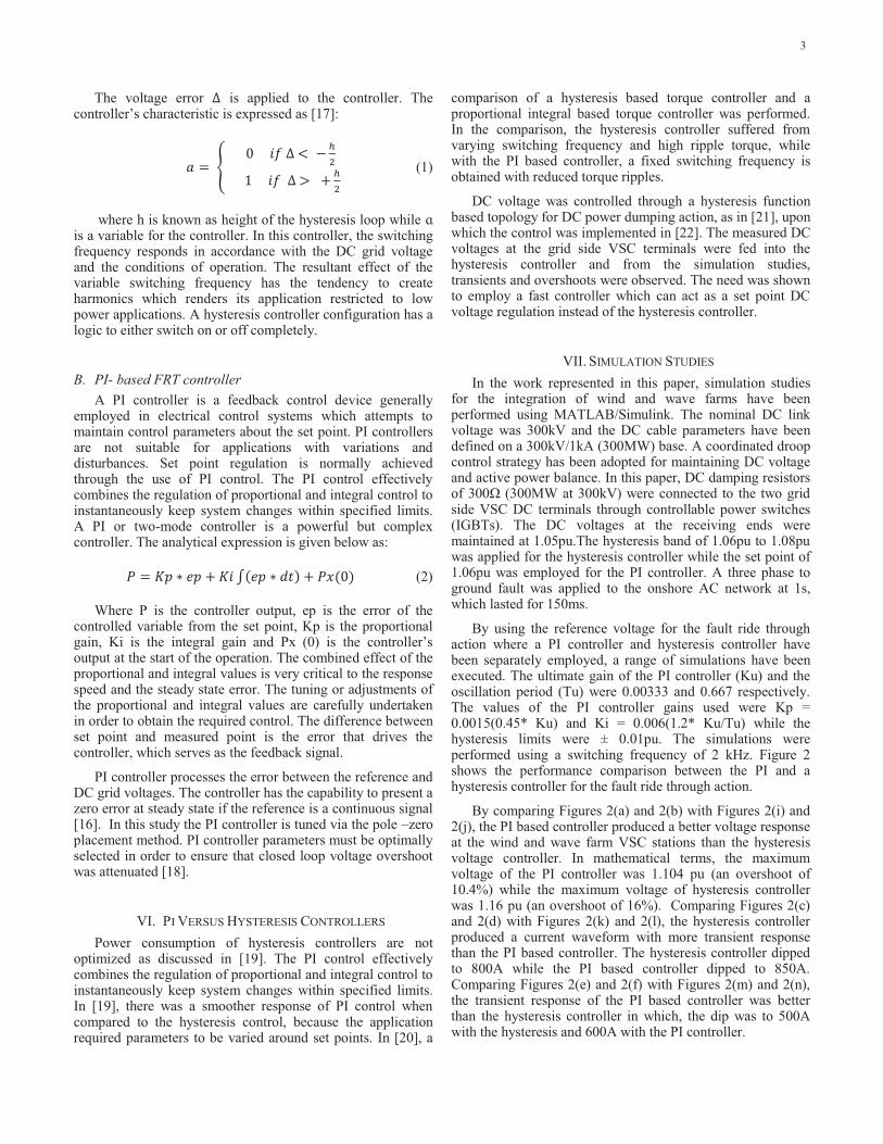
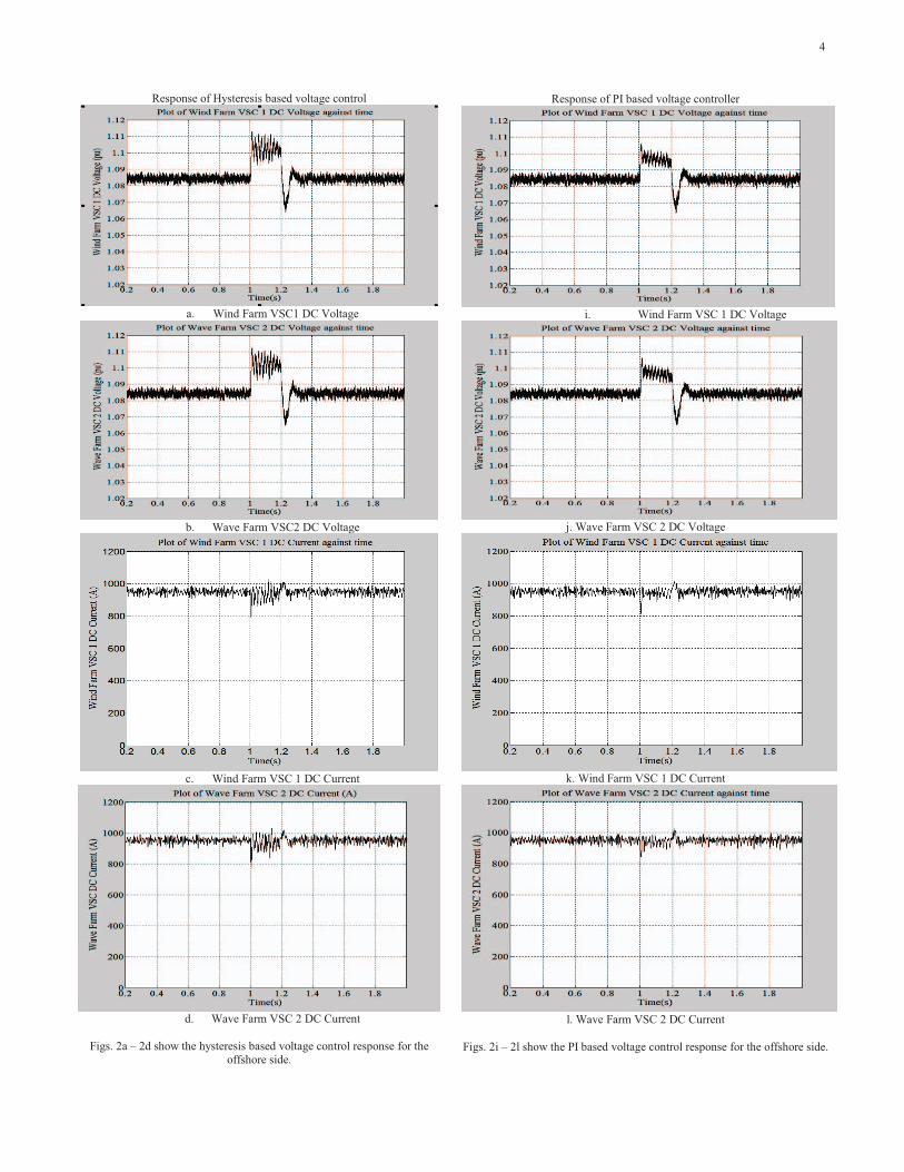
By comparing Figures 2(a) and 2(b) with Figures 2(i) and 2(j), the PI based controller produced a better voltage response at the wind and wave farm VSC stations than the hysteresis voltage controller. In mathematical terms, the maximum voltage of the PI controller was 1.104 pu (an overshoot of 10.4%) while the maximum voltage of hysteresis controller was 1.16 pu (an overshoot of 16%). Comparing Figures 2(c) and 2(d) with Figures 2(k) and 2(l), the hysteresis controller produced a current waveform with more transient response than the PI based controller. The hysteresis controller dipped to 800A while the PI based controller dipped to 850A. Comparing Figures 2(e) and 2(f) with Figures 2(m) and 2(n), the transient response of the PI based controller was better than the hysteresis controller in which, the dip was to 500A with the hysteresis and 600A with the PI controller.
3
Response of Hysteresis based voltage control
a. Wind Farm VSC1 DC Voltage
b. Wave Farm VSC2 DC Voltage
c. Wind Farm VSC 1 DC Current
d. Wave Farm VSC 2 DC Current
Figs. 2a – 2d show the hysteresis based voltage control response for the
offshore side.
Response of PI based voltage controller
i. Wind Farm VSC 1 DC Voltage
j. Wave Farm VSC 2 DC Voltage
k. Wind Farm VSC 1 DC Current
l. Wave Farm VSC 2 DC Current
Figs. 2i – 2l show the PI based voltage control response for the offshore side.
4
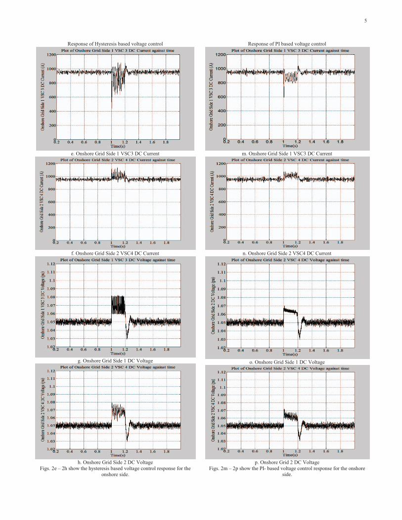
Response of Hysteresis based voltage control
e. Onshore Grid Side 1 VSC3 DC Current
f. Onshore Grid Side 2 VSC4 DC Current
g. Onshore Grid Side 1 DC Voltage
h. Onshore Grid Side 2 DC Voltage
Figs. 2e – 2h show the hysteresis based voltage control response for the onshore side.
Response of PI based voltage control
m. Onshore Grid Side 1 VSC3 DC Current
n. Onshore Grid Side 2 VSC4 DC Current
o. Onshore Grid Side 1 DC Voltage
p. Onshore Grid 2 DC Voltage
Figs. 2m – 2p show the PI- based voltage control response for the onshore side.
5
Comparing Figures 2(g) and 2(h) with Figures 2(o) and 2(p), the PI based controller gave a better DC voltage response than the hysteresis voltage controller. In summary, the DC voltage was regulated better with the PI than the hysteresis controller as the hysteresis controller maintained within the hysteresis band but the PI controller regulated and ensured 0.01 overshoot.
VIII. CONCLUSION This paper has examined the DC voltage and active power
balancing of a four VSC-based MTDC system employed for the integration of large offshore wind and wave farms. The use of DC damping resistors as employed in this study suggests this as the most convenient method for achieving onshore AC fault ride through. Two controller designs have been discussed: PI controller and hysteresis controller. The comparative study shows the PI is suitable for cases where a fixed varying switching is required for the control parameter. However, the PI control requires effort for tuning and there can be some overshoot above the set point. Overall, for the fault ride through application, the PI controller responses were superior to that of the hysteresis controller.
REFERENCES [1] E. Eriksson, P. Halvarsson, D. Wensky, and M. Hausler, ‘‘System
approach on designing an offshore windpower grid connection,’’ Proc. Fourth Int. Workshop on Large-Scale Integration of Wind Power and Transmission Networks for Offshore Wind Farms, Sweden, October 2003.
[2] N. Kirby, L. Xu, M. Lucket, and W. Siepmann, ‘‘HVDC transmission for large offshore windfarms, ’’ IEE Power Engineering Journal, vol. 3, pp. 135–141, Jun. 2002.
[3] D. Xiang, L. Ran, J.R. Bumby, P. Tavner, and S. Yang, ‘‘Coordinated control of an HVDC link and doubly fed induction generators in a large offshore wind farm,’’ IEEE Trans. Power Delivery, vol. 21, pp. 463–471, Jan. 2006.
[4] S. Foster, L. Xu, and B. Fox, ‘‘ Control of an LCC HVDC system for connecting large offshore wind farms with special consideration of grid fault,’’ in Proc. 2008 IEEE Power Engineering Society Conf., pp. 1-8.
[5] L. Xu, L.Z. Yao, and C. Sasse, ‘‘Grid integration of large DFIG based wind farms using vsc transmission,’’ IEEE Trans. Power System, vol. 22, pp. 976–984, Aug. 2007.
[6] G. Ramtharan, A. Arulampalam, J.B. Ekanayake, F.M. Hughes, and N. Jenkins, ‘‘Fault ride through of fully rated converter wind turbines with AC and DC transmission systems,’’ IET Renew. Power Gener., vol. 3, pp. 426 –428, December 2009.
[7] T. Ackermann, ‘‘Transmission systems for offshore wind farms,’’ IEEE Power Eng. Rev., vol. 22, pp. 23– 27, Dec. 2002.
[8] L. Xu, and B.R. Andersen, ‘‘Grid connection of large offshore wind farms using HVDC,’’ in Wind Energy, vol. 9, pp. 371– 382.
[9] C. Feltes, and I. Erlich, ‘‘Variable frequency operation of DFIG based wind farms connected to the grid through VSC-HVDC link,’’ in 2007 IEEE Power Engineering Society conf., pp. 1-7.
[10] P.A.Grain, O.Anaya-Lara, G.Burt, and J.McDonald, ‘‘Five-level VSC HVDC Transmission Systems Based on Modular Multilevel Converter,’’ Unpublished, presented at the 2nd EPE wind chapter semenar, Stockholm, Sweden, 2009.
[11] L. Jiao, G. Joos, C. Abbey, F. Zhou, and B.T. Ooi, ‘‘Multi-terminal DC (MTDC) systems for wind farms powered by doubly-fed induction generators (DFIGs),’’ in Proc. 2004 IEEE Power Electronics Society Conf., pp. 1413-1418.
[12] L. Tang, and B.T. Ooi, ‘‘Locating and isolating DC faults in multi- terminal DC systems,’’ IEEE Trans. Power Delivery, vol. 22, pp.1877- 1884, Jul. 2007.
[13] W. Yao, M.Chen, J. Matas, J.M. Guerrero, and Z.-M. Qian, “Design and analysis of the droop control method for parallel inverters considering the impact of the complex impedance on the power sharing,’’ IEEE Trans. Indus. Elect., vol.58, pp. 576-588, Feb. 2011 Trans. Power Delivery, vol. 3, pp. 549-557, Apr. 1988.
[14] R.S, Geetha, R. Deekshit, and G. Lal, ‘‘Performance analysis of a Voltage Source Converter HVDC system conncected to an independent Power Generating station,’’ in 2012 IEEE Power Electronics Drives and Energy Systems Conf., pp. 1-7.
[15] L. Xu, L. Yao, and M. Bazargan, ‘‘DC grid management of a multi-terminal HVDC transmission system for large offshore wind farms,’’ in Proc. 2009 First SUPERGEN Conf., pp. 1-7.
[16] A. Nachiappan, K, Sundararajan, and V. Malarselvam, ‘‘Current controlled voltage source inverter using Hysteresis controller and PI controller’’, EPSCICON International Conf., pp. 1-6, January 2012.
[17] M. Lafoz, I. Iglesias, C. Veganzones, and M. Visiers, ‘‘A novel double hysteresis-band current control for a three- level voltage source inverter’’, IEEE Trans. On Power Electronics Specialists, vol. 1, 2000, pp. 21-26.
[18] A.J. Mahdi, W.H.Tang, L. Jiang, and Q.H. Wu, ‘‘A Comparative study on variable – speed operations of a wind generation system using vector control,’’ EA4EPQ International Conf. on renewable energies and power quality, March 2010.
[19] A.S. Soumya, and G.K. Purushothama, ‘‘Case study of Hysteresis and PI control as applied to Engine Coolant Temperature Control and Proposal of a combination Control logic,’’ in Computing, Electronics and Electrical Technologies Conf., pp. 489-494, March 2012.
[20] T. Ramesh, and A.K. Panda, ‘‘Direct flux and torque control of three Phase induction motor drive using PI and fuzzy logic controllers for speed regulator and low torque ripple,’’ in Engineering and Systems Students Conf., pp. 1-6.
[21] I. Erlich, H. Wrede, and C. Feltes, ‘‘Dynamic Behaviour of DFIG- Based Wind Turbines during Grid Faults,’’ in Power Conversion Conference, pp. 1195-1200, April 2007.
[22] L. X, and, L. Yao, ‘‘DC voltage control and power dispatch of a multi- terminal HVDC system for integrating large offshore wind farms,’’ IET Renewable Power Generation Journal, vol. 5, pp. 223-233, May 2011.
6