impact of voltage source converter (vsc) based hvdc ... c20_impact of vsc hvdc... · it also offers...
TRANSCRIPT

1
Impact of Voltage Source Converter (VSC) Based HVDC Transmission on AC System
Protection
A technical report to the System Protection Subcommittee of the Power System Relaying and Control Committee
Assignment: Develop a report to the PSRCC describing Voltage Source Converter (VSC) HVdc systems and the impact on local AC system protection.
Chairperson: Joe Mooney Vice Chairperson: Ian Tualla Working Group Members: P. Beaumont, W. Brown, S. Chan, A. Deronja, N. Fischer, R. Hedding, M. Hilaly, K. Houser, B. Johnson, H. Kirkham, T. Manna, P. McLaren, R. Midence, S. Samineni, S. Subramanian, C. Vo, S. Ward, J. Wilson, A. Zamani, P. Zinck

2 TABLE OF CONTENTS I. INTRODUCTION ........................................................................................................................................................................ 3 II. REASONS FOR USING HVDC TECHNOLOGY AND COMPARISON OF AC AND DC SYSTEMS ................................ 3 III. VSC DESCRIPTION & TECHNOLOGY ................................................................................................................................. 4
A. VSC Converter Technology .................................................................................................................................................... 4 1) Introduction.......................................................................................................................................................................... 4 2) DC Current Flow ................................................................................................................................................................. 7 3) AC Current Flow ................................................................................................................................................................. 8 4) AC Real and Reactive Power Flow ..................................................................................................................................... 9 5) Reactive Power Control ..................................................................................................................................................... 10
B. Harmonics and Filtering ........................................................................................................................................................ 11 C. Control System, Start-up, Shut-down, DC Protection ........................................................................................................... 12
1) Converter Control Systems ................................................................................................................................................ 12 2) Start-up Procedures ............................................................................................................................................................ 12 3) Shut-down Procedures ....................................................................................................................................................... 12 4) Converter Valve Protection ............................................................................................................................................... 12 5) DC Protection .................................................................................................................................................................... 12
D. HVDC Response to Faults on the AC Power System ........................................................................................................... 13 E. AC Response to DC Faults .................................................................................................................................................... 14
IV. AC SYSTEM PROTECTION ................................................................................................................................................. 15 A. Converter Terminal AC Protection ....................................................................................................................................... 15 B. AC Line Protection ................................................................................................................................................................ 16
V. COMMUNICATIONS BETWEEN HVDC AND AC SYSTEMS ........................................................................................... 17 A. DC Circuit breaker ................................................................................................................................................................ 17 B. Multi-terminal Systems ......................................................................................................................................................... 18
VI. CONCLUSIONS ..................................................................................................................................................................... 18 VII. REFERENCES ....................................................................................................................................................................... 19 APPENDIX I. VSC Converter Effect on Power Line Carrier Equipment Performance ................................................................ 20
1) Incident Analysis ............................................................................................................................................................... 20 2) Power Line Carrier Measurements .................................................................................................................................... 20 3) Solution .............................................................................................................................................................................. 21
I. REFERENCES ........................................................................................................................................................................... 23

3 I. INTRODUCTION High-voltage direct current (HVDC) transmission has been in commercial operation since the 1950’s. The dominating technology used for HVDC has been line current commutated (LCC) systems utilizing thyristor-based technology. At present, there are LCC systems with operating voltage of up to ±800 kV and power transfer levels of more than 8000 MW, with larger systems under study. LCC systems require significant reactive support at the rectifier and inverter terminals as well as harmonic filtering. The benefit of LCC HVDC systems is their high capacity in terms of voltage levels and power flows. The impact of LCC systems on ac system protection is well established and described in CIGRE TB 484 “Impact of HVDC Stations on Protection of AC Systems”. In the 1990’s the voltage source converter (VSC) topology that had been used for decades in variable-speed motor drives began being used in HVDC applications. At about the same time, insulated-gate bipolar transistors (IGBT) were developed that had ratings and capabilities needed for HVDC applications. The first of these systems was put into service in 1997. HVDC schemes utilizing this technology are referred to as Voltage Source Converters (VSC) HVDC. The rapid proliferation, increasing size, and technical advances of VSC HVDC technology in recent years had been a revolutionary impact on large-scale electrical power transmission in some parts of the world. The VSC HVDC has several key control options such as independent active power and reactive power control, islanded network operation (black start capability), and static synchronous compensator (STATCOM) mode operation. In recent years, VSC systems increased in power rating, came down in cost and improved in efficiency to the point where they are becoming the application of choice in many instances. In the future, they could become the standard for new installations. As compared to LCC HVDC systems, VSC systems respond to ac and dc system conditions differently. In contrast to LCC, the polarity of the dc voltage in a VSC HVDC system is constant and the direction of power the transfer is changed by changing the polarity of the dc current. In fact, it is simpler to control and protect multi-terminal systems using VSC technology. This is due both to fundamental differences in converter topologies and the higher degree of control that is available in a VSC system. The rectifiers and inverters can respond very quickly and appear as “ideal sources” in nearly any fashion desired by control engineers. That means the response of VSC HVDC systems to ac system faults and dynamic conditions is much different than conventional ac system sources, such as ac generators. This report provides background material on the fundamental operating characteristics of VSC systems and investigates their impact on the ac system protection used near the converters.
II. REASONS FOR USING HVDC TECHNOLOGY AND COMPARISON OF AC AND DC SYSTEMS The classical application of HVDC systems is in the transmission of bulk power over great distances because of operational efficiencies (minimized losses) as well as an advantage in overall system cost when compared to the ac power system equivalent. A rather significant advantage of a HVDC interconnection is that there is no stability limit related to either the amount of power moved or the distance of transmission. Common ac power transmission limitations include: acceptable voltage variation over the transmission distance and expected load levels, maintaining synchronous operation across the transmission line after a disturbance, and the economic impacts of mitigating these common limitations. Consider the interconnection of two independent power systems to be interconnected by a synchronous ac link or links. Common rules concerning technical considerations such as voltage control, frequency control, reliability, security, control of reserve capacity and so on will need to be respected. Studies of the new combined system will be needed considering the structure of the systems, the relative strength of the systems, and the number of interconnecting lines to assess whether or not stability problems may occur. In a number of cases a second ac link will be necessitated for reasons of reliability. By contrast, interconnecting the systems with HVDC technology removes any constraints concerning both stability problems and control problems. The common rules listed previously concerning security and so on can primarily be left within the respective jurisdictions of the two independent ac systems. An HVDC link provides a cost-effective power transmission solution for transferring bulk power over long overhead or underground transmission system. It also offers decreased congestion or reduced footprint (i.e., the use of a transmission line corridor of a land or water route) compared to a conventional three-phase ac transmission of similar power transfer capability. A HVDC monopole transmission line requires as few as two conductors (only one for submarine with seawater return) as compared to an ac transmission line utilizing three conductors. With respect to submarine or underground interconnections, as distance increases, ac cables experience an increasingly wide variation of voltage with power flow until the current rating of the cable is fully taken up by its charging current. Considering this type of application, reactive compensation units really cannot be installed, especially in submarine applications. Even with the use of XLPE (cross-linked polyethylene) cable, the maximum practical distance for submarine ac cables is approximately 100 km (62.14 miles). Beyond this distance, HVDC remains the only technically viable solution. An HVDC connection requires

4 only positive and negative (pole and return) conductors, or in some cases a single conductor with sea return. In general, there is essentially no practical technical limitation to the circuit length except, of course, for cost. VSC HVDC with an extruded polyethylene or mass impregnated dc cable link makes it possible for HVDC transmission to become economic at lower power levels (up to approximately 200 MW) and over a transmission distance of as little as roughly 40 km (24 miles). In applications where the electric power is to be transmitted from a remote generation location across different jurisdictional boundaries, countries or areas within a country and it is of economic or political importance to offer a connection to potential partners in the areas that the proposed line traverses, a multi-terminal HVDC system is a possibility. HVDC multi-terminal systems allow more participants to be interconnected. Multi-terminal HVDC systems have been proven to be feasible. For example, Nan’ao three-terminal ± 160kV/200MW-100MW-50 MW VSC-HVDC in Shantou, China is the world’s first multi-terminal VSC-HVDC link, in operation since December 2013 [1]. AC load flow depends on the angular difference between voltage vectors in various segments of the electrical power system. These angles are dependent on the balance of power and cannot be directly adjusted. Also, changes in power generation or load demand will cause a change in system frequency that has to be restored by altering the generation as a whole. Since this has to be accomplished by generator speed controllers, the frequency restoration tends to be a slow action or reaction. System stability also relies on the flexibility of the system to allow automatic adjustment of the voltage vectors. If stability becomes a problem that requires fast frequency control, then HVDC systems can meet this challenge by drawing energy from the remote network to support the ac system. Because of the ability to change the operating point virtually instantaneously, HVDC can increase (or reduce) active power flow into the disturbed system to control the frequency much faster than a normally controlled generator. An ac system event such as a fault causes depression of the voltage during power swings. With an HVDC link between independent ac systems, the voltage depression does not transmit across the dc barrier. These swing-related voltage depressions may emerge on the other side of the dc link as a reduction of the power; however, voltage will substantially remain unaffected. When ac network systems are expanded, generally leading to increased interconnectivity of the system components, the short circuit level of the system increases. Switchgear will often need to be upgraded or replaced as a result of this increased fault duty (often at high expense). An HVDC link, by design, does not significantly increase the short circuit current as do conventional generation sources. On the other hand, a VSC system can also be used to provide reactive power support to the ac system much like a STATCOM. The reactive power support can be utilized even when the HVDC link is not transmitting real power. This is one of the primary advantages of VSC systems over LCC systems where the LCC system only consumes reactive power and additional reactive resources must be provided to balance the ac system.
III. VSC DESCRIPTION & TECHNOLOGY
A. VSC Converter Technology
1) Introduction The development in power electronics leading to the introduction of insulated gate bipolar transistor (IGBT) based switching valves in the 1980s made a new HVDC technology economically feasible. Voltage sourced converters (VSC) are also referred to as self-commutated converters. The major difference between voltage sourced converter technology and conventional line commutated technology is that VSC HVDC systems use switching devices such as IGBTs, which are able to switch off current. Hence there is no demand for a synchronous ac voltage source for the commutation process [2]. On the other hand, LCC technology has a number of operational constraints, which limits its use for some applications. Major restrictions include:
• The need for a relatively strong ac system on both sides of the HVDC link with an effective short circuit ratio of > 2.5 for reliable operation
• Requirements for ac harmonic filtering equipment to be provided at each converter station • Limited control of the reactive power interchanges with the ac system.
The advent of VSC HVDC technology removes many of these limitations. VSC HVDC is based on self-commutated power electronics and hence it can operate into very weak ac systems, indeed it can operate into a passive system, that is, one with no source of power generation. This makes it ideal for connecting island loads or “black starting” ac systems. As the VSC converter generates an output voltage waveform of controlled magnitude and phase angle, it can control real power flow between the two stations and also independently control reactive power flow into the ac systems. Thus, it has built-in STATCOM functionality.

5 VSC technology allows for immediate bi-directional power flow made possible through use of IGBT gate switching controls to switch the current. LCC technology can achieve bi-directional flow however requires change to the dc voltage polarity which requires switching of converter station dc yard equipment VSC technology was first tested for HVDC transmission in 1997 [3] and since this time it has gone through several iterations of technology. Early schemes used a simple 2-level converter utilizing Pulse Width Modulation (PWM) technology to synthesize the ac waveform. However, such converters suffered from relatively high losses (3-4% of power transfer per converter) and the converter topology was changed to a 3-level converter, again using PWM. Later designs then went back to a 2-level converter design but using a modified PWM control scheme known as optimal PWM (OPWM) or selective harmonic elimination (SHE). Using OPWM reduced the switching frequency of the converter and hence the losses, albeit at the cost of increasing selected ac harmonics; as such, the design required some sort of passive filtering.
Figure 1: A typical multi-module converter arrangement and output ac waveform
Today, the state of the art technology in VSC HVDC is known as the modular multi-level converter (MMC), shown in Figure 1. Unlike the earlier topologies of VSC, the voltage used to synthesize the ac voltage in MMC topology does not experience large, rapid voltage steps equal to the dc link voltage; instead the secondary voltage waveform contains only small steps in voltage. These small steps are created by the individual switching of elements within the converter connected together in series in an arrangement known as a “chain-link” [4]. A single HVDC converter may consist of several hundred elements connected together on each ac phase leg. The ac voltage step size decreases with the number of modules connected in series. More importantly, the converter switching losses decrease with the size of the voltage step, decreasing the switching losses for MMC systems to approximately 0.5-1% per converter. The generic circuit arrangement of a modular multi-level converter is shown in Figure 2. The major components are (i) the interconnection (converter) transformer, (ii) the valve reactors and (iii) the converter valves. The interconnection transformer may or may not include an on-load tap changer depending on the weighted importance of reduced losses versus reduced maintenance. The valve reactors are typically air-cored air-insulated reactors and are needed to limit the rate of rise of the current in each phase during switching of the semi-conductor devices, and also act to limit fault current amplitudes for faults inside the power electronic converters or on the dc system. On the ac side of the converter bridge there is a “soft start” resistor, which is used during the initial start-up sequence, and a disconnect switch to short out the resistors after start-up.
+ V
- V
+ V
- V
= “Chain-Link” ModuleC
urre
nt (k
A)
Volta
ge (k
V)
Time (ms)
AC Supply VoltageConverter VoltageAC Phase Current
Cur
rent
(kA
)
Volta
ge (k
V)
Time (ms)
AC Supply VoltageConverter VoltageAC Phase Current

6
ConverterTransformer
ConverterValves
ConverterValves
LimbReactors
LimbReactors
Soft StartResistors
Figure 2: VSC Modular Multi-level Converter topology
The submodules within the converter circuit can be either ‘full-bridge’ or ‘half-bridge’ circuits. The ‘full-bridge’ circuit is able to reverse the dc voltage as indicated in Figure 3(a). The submodules consist of four IGBTs, each with an anti-parallel connected free-wheeling diode. The full-bridge submodule has the ability to interrupt the supply of dc fault current from the ac system since any path from ac to dc has a controlled switch. The full-bridge submodule MMC may eventually be the system of choice for VSC HVDC systems utilizing overhead lines due to the ability to interrupt fault current. In addition, a MMC based on full-bridge submodules has the ability to reverse the polarity of the dc voltage, raising the possibility of hybrid HVDC systems with both VSC and LCC converters. . The half-bridge circuit is comprised of two fewer IGBTs per sub-module, as shown in Figure 3(b). The reduction in devices decreases the converter losses by approximately 50% over the full bridge design in addition to decreasing converter construction costs. As a result of this, all operating systems at the time this report was written use half-bridge submodules. The first system using full-bridge modules under construction in Germany in an application using overhead lines with a higher likelihood of dc faults. However, the half-bridge submodule topology has the drawback that it provides an uncontrolled path for the ac system to feed dc faults, as is the case with two-level and three-level VSC as well. As a result, current VSC HVDC installations require additional circuit elements to protect the circuit in the event of a dc side fault, typically relying on ac side breakers to interrupt dc faults. Due to this limitation, the majority of VSC HVDC systems use underground or submarine cables to reduce exposure to dc faults, where a dc side fault will almost certainly be permanent and will necessitate tripping the dc connection. The sub-modules in Figures 3(a) and 3(b) also include thyristors that can be gated to bypass individual modules in the event of a module failure. VSC HVDC systems are typically connected in a symmetric monopole configuration as shown in Figure 2. Unlike a LCC bipole configuration, there is a single converter controlling both poles. This lowers the system level reliability for n-1 contingencies.

7 As a result, several utilities have specified new VSC HVDC systems with two parallel VSC systems so a dc line fault or converter failure only results in a 50% decrease in power capability.
Full-BridgeCircuit
ConverterTransformer
Chain LinkSub-Module
ConverterTransformer
Half-BridgeCircuit
Chain LinkSub-Modules
(a) MMC VSC with Full-Bridge Sub-Modules (b) MMC VSC with Half-Bridge Sub-Modules
Figure 3: HVDC MMC VSC Sub-module alternatives
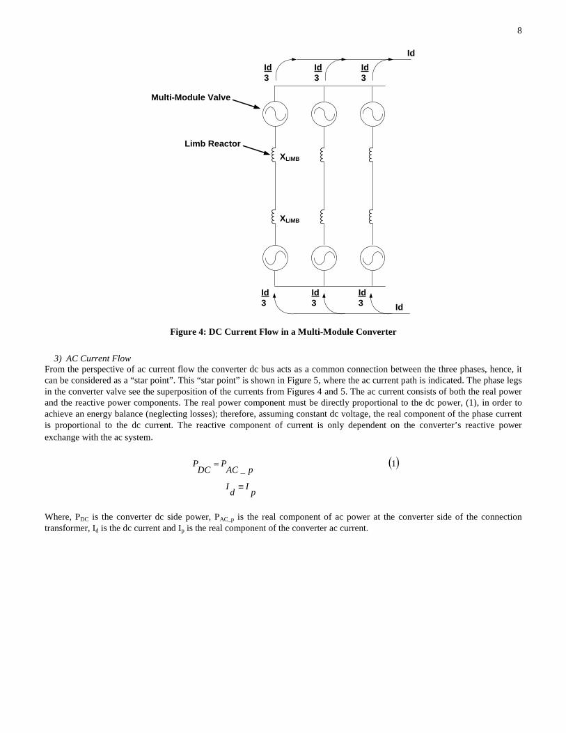
2) DC Current Flow The three converter phases can be considered as parallel branches when viewed from the dc side, as shown in Figure 4. Energy flows from the ac system to the dc system through the MMC. While the total number of un-bypassed sub-modules within each phase will be the same, the number of un-bypassed sub-modules in the top valve compared to that number in the bottom valve will vary depending on the instantaneous ac phase voltage. These three parallel converter valve limbs will act as a controlled current transferring power to or from the dc circuit. As the three converter valve limbs are in parallel and have an equal number of un-bypassed sub-modules each limb will continuously conduct 1/3 of the total dc current as shown in Figure 4 which only shows the dc current behaviour.
8
Figure 4: DC Current Flow in a Multi-Module Converter
3) AC Current Flow From the perspective of ac current flow the converter dc bus acts as a common connection between the three phases, hence, it can be considered as a “star point”. This “star point” is shown in Figure 5, where the ac current path is indicated. The phase legs in the converter valve see the superposition of the currents from Figures 4 and 5. The ac current consists of both the real power and the reactive power components. The real power component must be directly proportional to the dc power, (1), in order to achieve an energy balance (neglecting losses); therefore, assuming constant dc voltage, the real component of the phase current is proportional to the dc current. The reactive component of current is only dependent on the converter’s reactive power exchange with the ac system.
( )1_
pIdI
pACP
DCP
≡
=
Where, PDC is the converter dc side power, PAC_p is the real component of ac power at the converter side of the connection transformer, Id is the dc current and Ip is the real component of the converter ac current.
XLIMB
Limb Reactor
XLIMB
Multi-Module Valve
IdId3
Id3
Id3
IdId3
Id3
Id3

9
Figure 5: AC Current Flow in a Multi-Module Converter
4) AC Real and Reactive Power Flow Let us now consider the simplified representation of the multi-module VSC circuit shown in Figure 6. From the phasor diagram shown in Figure 6(b) it can be seen that the real power (PAC) and reactive power (QAC) exchange with the ac system can be defined by (2) and (3) respectively, neglecting the small resistance in the limb reactors and the converter transformer.
( )2)(
2
δSinLIMBX
TX
convVACVACP ⋅
+
⋅=
( )3
2
)(cosACV
LIMBXTX
ACVconvVACQ ⋅
+
−⋅=
δ
Where, VAC is the ac system voltage, Vconv is the synthesized ac converter voltage, XT is the converter transformer impedance, XLIMB is the reactance of the limb reactors and δ is the angle between the ac system voltage and the synthesized ac converter voltage.
XLIMB
XT
Limb Reactor
ConnectionTransformer XLIMB
Multi-Module Valve
Iac2
Iac2
Iac2
Iac2
Iac2
Iac2
DC BusAC “Star” point

10
Figure 6: AC Current Flow in a Multi-Module Converter (a) Equivalent Circuit (b) Phasor Diagram
5) Reactive Power Control The MMC operates as a four-quadrant device, i.e., it is able to import/export real power and import/export reactive power to the ac systems at both ends of the transmission link. The reactive power can be controlled independently at each converter station. If no power flow is required or possible, e.g. due to a cable fault, each converter station is able to operate as a STATCOM, providing reactive power support to the local ac system. As indicated in Figure 7, there are limitations to the reactive support capability from a VSC converter. The multi-module converter current limit capability contour is shown in Figure 7. It can be seen in this figure that the constant MVA contour of the complete system is dependent on the amplitude of the steady-state ac system voltage. Further, in the capacitive reactive power sector, the output is constrained by the valve voltage limit, which varies with the ac system steady state voltage. More capacitive reactive power output is available for minimum system voltage, when it is needed, than for maximum system voltage. The design of the converter must also respect the dc current limit imposed by the dc circuit (for example the cable). The multi-level converter design can be adjusted to match customer requirements for real power and reactive power demand at the terminals of the converter station, or Grid Code requirements on operating power factor range. The full-bridge circuit, shown in Figure 3, is less constrained in terms of capacitive reactive power output than the half-bridge circuit, and is able to deliver full capacitive reactive power output.
Vvsc
Vac
VRe
Im
δ
XTXLIMB
2
VAC VVSC
ICONV
ΔV
(a)
(b)
I

11
Figure 7: Real/reactive power capability diagram When connected to existing ac systems employing conventional Reactive Power Compensation equipment such as shunt reactors, the designers need to ensure that the converter station and existing ac station reactive power controls are coordinated. The is critical to the reliability and longevity of the existing ac system reactive power switching devices (breakers, etc.); if the controls are not coordinated the result would likely be “hunting” by the ac system reactive power controls and associated excessive operation of ac breakers.
B. Harmonics and Filtering The primary harmonic production from voltage source converters is in the form of voltage harmonics. The distortion in voltage leads to distortion of the current waveform, resulting in current harmonics. The primary filter mechanism for reducing voltage harmonics is adding series reactance on the ac side of the converter or a tuned series LCL filter, also on the ac side of the converter. This reactance serves to protect the IGBTs by limiting the rate-of-rise of the current. Tuned shunt filters are added to sink current harmonics when necessary. It should be noted that the harmonic content of the output waveform of a VSC HVDC converter depends on the converter topology. Schemes using PWM switching based on two-level or three-level converters produce harmonics near the effective switching frequency and multiples of the switching frequency. The switching frequency is often an integer multiple of the fundamental ac frequency. If different converter terminals on the dc system connect to systems at different frequencies there can be interharmonics between the two switching frequencies. PWM based schemes require shunt harmonic filters, generally high pass filters with a tuning frequency at the switching frequency or at the lowest interharmonic. Typical schemes have a series reactor in addition to the transformer reactance. It is worth noting that advanced switching techniques such as space vector modulation (SVM) and selective harmonic elimination (SHE) can also improve the harmonic profile of the output voltage of the VSC HVDC as noted in Appendix 1 of report. Schemes using MMC topologies produce minimal harmonics due to combination of the number of switching levels and the small voltage step associated with each level. They only require series limb reactors, as shown in Figure 4, for the purpose of limiting currents. Additional shunt harmonic filters are added in some instances based on project requirements for filter performance, for example on ac voltage distortion levels at the point of interconnection [5]. DC filter requirements depend both on the converter topology and the nature of the dc system. The dc capacitors, which are an essential part of the VSC design, can provide a significant degree of voltage harmonic filtering. Two-level and three-level converters require shunt harmonic current filters on the dc side. MMC-based systems required less dc side filtering. If the converter is connected directly to an underground or underwater dc cable, no additional dc filtering is needed in many cases.
Minimum Steady-State Voltage
Maximum Steady-State Voltage
Nominal Steady-State Voltage
DC Current Limit
Valve Voltage Limit
Minimum Steady-State Voltage
Maximum Steady-State Voltage
Nominal Steady-State Voltage
Real Power
Reactive Power

12 However, in cases where dc overhead lines are coupled to the converter it will be necessary to perform studies to determine dc filtering needs. But, as a general rule, dc-side harmonic current filters are usually required [6]. The high rate-of-change of voltage (dv/dt) associated with the switching of the IGBT in the valves results in high frequency (HF) noise. To limit radiation of HF noise, the converter valves and housing are shielded. Radio interference filters are normally installed to further limit radiated interference. Filters have also been added to some systems to block interference with power line carrier (PLC) systems.
C. Control System, Start-up, Shut-down, DC Protection
1) Converter Control Systems The converter controls normally have two or possibly three cascaded levels. In the case of a two level control scheme, the outermost level receives set point commands from a system operator. In a two terminal point-to-point system one converter normally regulates the dc line voltage and the other converter receives a power set point. In most systems the inner controllers are fast current regulators that decouple the real and reactive components through application of the Park’s transformation to the synchronous reference frame.
Newer control systems may have both positive and negative sequence control loops. The negative sequence control loops are often set to regulate negative sequence currents to zero.
2) Start-up Procedures The ac side of the converter bridge includes a “soft start” resistor which is used during the initial start-up sequence to charge the dc capacitors from the ac system. When the dc capacitors are fully charged, operation of the converters is initiated and the soft-start resistor is shorted out by a disconnect switch. Once the dc voltage is up to a set level, the system start up can proceed, with subsequent steps dependent on the application and requirements of the system owner.
3) Shut-down Procedures Standard shut down procedures are vendor specific and also vary by application.
4) Converter Valve Protection Converter valve protection will vary with manufacturer, but the following lists typical functions:
• Asymmetry protection is used to detect the presence of persistent fundamental voltage caused by severe unbalance conditions, for example, single-phase-to-ground faults in the ungrounded ac connection between the transformer and the converter. This protection will initiate a block of the IGBTs and trip of the ac side breaker.
• Valve reactor overcurrent protection is used to detect overcurrent in any of the six converter limbs and block the firing
of the IGBTs in response and trip the ac breaker. The protection will also fire the bypass module thyristors in MMCs.
• Valve current differential protection is used to detect faults between the converter transformer and the limb reactors (including the valve reactors). This protection will initiate a block of IGBT gating and trip ac breakers.
5) DC Protection Some of the protection schemes associated with an HVDC converter take measurements from the dc circuit and, thus, they cannot make use of “off-the-shelf” ac protection relays. These protections are therefore provided by the converter manufacturer as part of the total equipment supply. Such protections typically sit within hardware specific to the converter manufacturer. In order to provide redundancy these non-conventional protections are typically duplicated within the converter station (see the dc side of Figure 8).
• DC overcurrent protection is used to detect overcurrent in the dc link in order to (i) block gating of the IGBTs, (ii) trip the ac breaker, (iii) fire the bypass thyristors in the case of MMCs.
• DC current differential protection is used to detect ground faults on the dc side of the converter or within the converter circuit up to
the converter transformer to initiate a block and trip the corresponding ac circuit breaker(s).
• DC line voltage unbalance Protection is used to detect deviations between positive and negative poles of the dc line voltage to ground and to block IGBT firing and trip the system.
• DC line overvoltage protection is used to detect overvoltage in either the positive and negative pole of the dc line voltage to ground
and to block IGBT firing and trip the system.

13
• DC undervoltage protection is used to detect undervoltage in either the positive and negative poles of the dc line voltage to ground and to block IGBT firing and trip the system.
D. HVDC Response to Faults on the AC Power System During ac system faults and post-fault recovery, overvoltage, undervoltage and/or phase-angle swing conditions appear [8]. In this case, the converter is able to limit the increase of the current flowing through the valve and the phase/valve reactor without any stress on components. For asymmetric faults, a negative-sequence voltage arises of up to 30% to 50% of the normal voltage, which may result in valve blocking and the surge arresters will most likely activate to protect the valves from overvoltage. Surge arresters are applied to protect the converter from lightning overvoltage, switching overvoltage following fault clearing and/or resonant overvoltages which are transmitted to valves and phase/valve reactors via the incoming ac bus. As mentioned in Section III, the VSC converters control real and reactive power independently. Depending on the requirements of the system owner, the reactive power set point could be zero, or it could be specified by the system operator, or it could vary to regulate voltage magnitude at the system bus. In addition, the VSC controls have a fast current regulation control loop to protect the IGBTs from currents beyond the device ratings, typically 1.1-1.5 times the rated converter current, typically responding within a quarter to a half cycle to lower the steady-state fault current based on the maximum current limit set in the controls. The momentary peak current for some installations can be as high as 2-3 per unit. The control schemes are also often controlled to regulate negative sequence current from the converter to zero. Finally, the converters' transformers are three-wire systems on the Converter-side so the converter itself does not supply zero-sequence current.
To a limited extent, the behavior of the fault currents provided by the converter to supply an ac fault can be specified by the owner of the VSC based on the system requirements listed in the initial bid. Some system owners have specified that converters supply higher fault current levels, which has resulted in modifications to the devices in the VSC as well as increasing cost of the installation.
The converter manufacturers have default response behaviors in the controls. In some cases, this can include continuing to supply current at the pre-fault power factor, or varying the power factor to supply reactive power to boost local voltage. The converter has limited overvoltage tolerance. If a fault raises the terminal voltage above a set threshold, in some cases 1.05 times the pre-fault terminal voltage, the converter will reduce its output current or change the current angle to bring the voltage back down to the pre-fault level.
Some jurisdictions have specific guidelines for fault current response for VSC HVDC converter. Some vendors also provide system owners with ability to program the response to faults in the converter controller.
Once the initial transient peak has passed, the current magnitude and angle are then functions of the voltage magnitude on the network side of the transformer. The current injected by the VSC converter lags the VSC converter’s terminal voltage when voltage drops during a fault. In contrast, the current injected by conventional synchronous machines during a fault is depended on the impedance of the generator and the power system equipment elements between the generator and the fault. Since the impedance of the generator is mostly inductive, for faults close to the terminal of the generator, the current injected by the generator will lag the terminal voltage by close to 90 degrees; regardless of the magnitude of the generator's terminal voltage. The following describes the response of one specific VSC converter:
• When voltage drops during a fault, the angle of positive sequence current (out of the converter) relative to positive-
sequence voltage goes from near zero when the positive-sequence voltage is near 1.0 pu, to minus 90 degrees when the positive-sequence voltage is near zero. The converter automatically limits its current output to 1.1 times full load current.
• When the voltage magnitude drops below 0.5 per-unit, the converter’s current magnitude is reduced to 0.5 full load current. The amount of current reduction can be programmed in the controls by the user.
The converter controls are designed to prevent the converter from tripping off line for ac faults unless the fault persists. As a result, the converter will not shut down for faults on the network side of the transformer. The converter will shut down only when a fault reduces any of the phase voltages to zero or nearly zero at the converter terminal for a sustained period.
In summary, because of differences in control settings from different manufacturers, and the ability of system owners to specify and in some cases program the response of the converters to ac faults, there isn’t a single set of responses that can be predicted.

14 E. AC Response to DC Faults During internal faults in a VSC substation the VSC valve is exposed to greater overvoltage and overcurrent than those experienced during ac system faults [8]. The type and location of the fault, transformer winding configuration and grounding arrangement of the VSC substation determine the fault severity and characteristic. Among the component failure faults, the valve short-circuit failure mode and the valve open mode failure are the worst cases. The valve short circuit failure results in overcurrent due to discharge of the VSC dc capacitors, while a valve open mode failure will lead to overvoltage of the faulted IGBT by superimposing the whole dc voltage on them. In symmetric monopole systems, the healthy pole voltage increases in the event of ground fault of the other pole. The filter bus arrester and the dc bus arrester can limit this overvoltage. However, when it comes to a bipolar short circuit fault, the freewheeling diodes in the converter valve are subject to high currents derived from ac system before the tripping the ac breakers, even if the converter is blocked. In an asymmetric monopolar system, the pole to earth fault is similar to that in a symmetric monopole system [7]. For lightning strikes, there is no obvious overvoltage on the VSC valve due to the protection provided by the arrester. The anti-parallel diodes inherent in the VSC topology provide an uncontrolled path through the converter allowing the ac system to feed dc pole-to-pole faults if the converters are two-level or three-level type, or are based on half-bridge MMCs. However, a dc system using MMCs based on full bridge modules as shown in Figure 3(a) is able to interrupt dc fault currents by blocking the IGBTs. In order to reduce exposure to dc faults, nearly all VSC HVDC systems at the time this document was written were either back-to-back converters or were based on underground or underwater cables. The first full-bridge module based MMC system was also under construction in Europe using full-bridge modules in part due to the use of overhead line construction. Since the VSC is unable to block dc fault current, all VSC HVDC schemes presently trip ac circuit breakers to clear dc-side faults. The specifics of the dc fault detection scheme, trip logic and trip command vary with the equipment vendor. But in most cases, when the converter protection detects a dc fault based on the high current, it sends a trip command either to a relay controlling the ac breakers or directly to the ac breaker(s) [5]. There is generally no transfer trip command to open the ac breakers at the other converters in the system. Instead each converter relies on local measurements and protection action. Additional impedance, normally in the form of inductance, is added on the ac and dc sides of the converter to limit the rate of rise of the dc fault current as well as the total fault current to within the power semiconductor device limitations. Some vendors specify IGBT packages with diodes that have current ratings two to three times higher than the IGBT current ratings to help withstand dc fault currents. VSC HVDC transmission systems using full-bridge MMCs are able to use converter control action in order to block fault current in the event of dc faults. Blocking the IGBTs will bring the converter current to zero and block discharge of the submodule capacitors into the fault. Present VSC HVDC systems do not use HVDC breakers for protection against dc faults. The HVDC breakers employed as earth return path breakers in LCC HVDC systems have response time on the order of 400 ms and are too slow for protection in VSC systems. One manufacturer has developed a hybrid HVDC breaker capable of interrupting dc faults in approximately 2 ms, but with limited interrupting capability. The major HVDC converter manufacturers each have programs for developing HVDC circuit breakers capable of similar response times. The majority of VSC HVDC systems are point-to-point configurations with a converter terminal at each end. At present there are several multi-terminal HVDC (MTDC) systems in operation, two as demonstration projects in China. VSC based MTDC systems have the converters connected in parallel (pole-to-pole) with the potential for parallel transmission paths. The systems currently in operation utilize ac breakers as the primary fault interruption technology for dc side faults, with the entire dc grid being de-energized in response to a dc fault. The objective of the vendor programs developing fast HVDC circuit breakers is to develop the capability to interrupt only a faulted dc line within 2-5 ms rather than tripping the entire dc grid. The fast response time is necessary to protect both the IGBTs in the VSC and the dc system integrity.

15 IV. AC SYSTEM PROTECTION
A. Converter Terminal AC Protection The basic functionality of the protection scheme associated with a VSC system is the same as that associated with any electrical plant, that is:
• Limit damage to faulted equipment • Isolate faulted equipment • Minimize fire risk • Minimize hazards to personnel; and • Protect ac system from control mal-operation due to HVDC controllability
The principal stresses on the converter station equipment can be categorized as:
• Overvoltage o Surge Arresters for transient and temporary overvoltage o AC fault clearance o Over excitation o Control action
• Overcurrent o Main circuit design o Short circuit, pole to ground o Short circuit across a valve
Much of the protection needs and philosophy developed for the Line Commutated Converter (LCC) technology is directly applicable to VSC-based HVDC systems. The protections associated with a HVDC converter station can be broken down into two groups, “Conventional protection” and “non-conventional” protection. “Conventional” protections are those that could be found in an ac substation and not directly associated with the converter, whereas “non-conventional” protections are those that are applied specifically for the HVDC converter. Figure 8 shows a typical break-down of all of the protections associated with a single end of a VSC station.
Figure 8: Typical HVDC VSC transmission scheme protection arrangement

16 Conventional protection is typically associated with the passive equipment directly connected to the ac system. This includes the interconnection transformer, the busbar scheme and any ac harmonic filters (if required). In addition, the protection inside the point of common coupling is typically supplied by the VSC supplier. Typical protection schemes for the interconnection transformer and an ac harmonic filter are shown in Figures 9 and 10 respectively.
Figure 9: A typical converter transformer protection scheme Figure 10: A typical HVDC filter protection scheme Other protections associated with the converter, while being specific to the application, can still make use of “off-the-shelf” ac protection relays. AC undervoltage protection detects undervoltages on the ac side of the converter and will initiate a block and trip ac breakers(s) if the fault persists. Over-dissipation protection detects high energy dissipation through the soft-start resistor during converter start-up mode and to will initiate a block and trip when the limit is exceeded.
B. AC Line Protection HVDC systems do not contribute a significant amount of current to faults on the ac system and, thus, will not cause a significant increase in the total fault duty. This can be a benefit of integrating HVDC into ac systems with high fault current capabilities. The response of a VSC system is customized based upon the power systems need and the current rating of the IGBTs. Typically, a VSC system is limited to 1.2 to 1.5 pu current output for short circuit conditions. The control loops for the converters have the ability to regulate the ac current within a fraction of a cycle to protect the IGBTs from destructive current levels. In addition, the VSC control logic is typically designed so that the converter will only output balanced or positive-sequence current for all fault types. The converter transformers are typically wye-delta or wye-wye-delta with wye-grounded primary winding connection. The converter side of the transformer is connected wye-ungrounded or delta depending upon the transformer configuration. With this type of connection, the converter transformers can supply zero-sequence current for faults on ac systems The strength of the ac system in and around the VSC terminal is one of the determining factors in the evaluation of the ac system protection. If the converter is radially connected to the ac system (i.e., fed through a single transmission line) then the

17 protection system must be able to operate reliably under weak or zero source conditions that would be present at the converter terminal. If the converter station is connected to a tightly networked substation, the addition of the converter station will have little or no impact to the ac system or system protection. Selection of proper ground directional polarization for protecting a line terminating in a VSC system can be critical. Since the majority of VSC systems are designed to output no negative-sequence current for fault conditions, then negative-sequence polarization is a poor choice. Zero-sequence is a much better choice because the converter transformers are connected to provide a path for zero-sequence current given that the converter transformer is connected to the ac system. Some relay designs include negative-sequence supervision of phase distance elements. These elements may not operate correctly for a line that is terminated into a VSC system. This may require the use of a weak-infeed scheme to trip the VSC terminal for internal line faults. Typically, converter stations are located within or in immediate vicinity of the ac station to which they are connected. This poses difficulties in using distance or directional-based schemes and a line current differential scheme may be the best solutions for lines connecting directly to a VSC converter station. The line current differential relay operates on the total current to the fault which means that the relay will operate reliably for faults over the entire line without concern for the contribution from the VSC terminal. It is important for the protection engineer to understand how the VSC HVDC terminal responds to ac faults. Although some general information on VSC performance is given in this report obtaining a detailed description of how the VSC control system operates for balanced and unbalanced ac faults is important for developing correct relay settings.
V. COMMUNICATIONS BETWEEN HVDC AND AC SYSTEMS Protection of typical ac systems has been well researched and well documented; however, protection of HVDC systems is still relatively new to the protection engineer. This section will explain some of the additional communication requirements for HVDC systems. The primary focus will be on point-to-point HVDC systems; however, multi-terminal systems are being planned and technology is advancing as this report is being written. Additionally, there have been some recent developments of HVDC breakers; although with limited commercial availability and application to date. Having a dc breaker may lessen the communication requirements between the ac and dc systems, but may never fully eliminate it. Today, most VSC systems are point-to-point transmission lines or back-to-back systems using an ac breaker to trip for faults on the HVDC system. Thus, they require some form of interaction and communication between the controls and the relaying. For faults on the HVDC system it may actually be best to trip the ac system. Reliance on ac/dc coordination requires that the communications be treated as part of the overall system when it comes to reliability. It is common practice to utilize redundant communications to account for loss of communication between the controls and relaying. The topology of the system will play a large part in the type of communication required. Additionally, the controls of the HVDC system can act quickly during post fault conditions. This feature of the controls may be advantageous for power quality and riding through disturbances. A. DC Circuit breaker Let us consider faults on the ac system in Figure 11 at either F1 or F3. The relaying for the local ac breaker should detect the fault and issue a trip; however, it may be impossible or difficult for the HVDC system or the remote ac system to see the fault. This lack of fault detection is really due to the fact that the HVDC system is managed by a fast-acting control system where the converters quickly adjust to the fault making the post fault conditions less predictable. Therefore, for ac system faults it may be desirable to transfer trip breakers that may not see the fault and send a signal to “block” controls that will not automatically shut down. This concept of communication between controls and relaying may not be familiar to the protection engineer, but it is a typical requirement of HVDC systems. Now, let us assume a fault on the HVDC system F2 in Figure 11. The converter controls will see the increase in fault current and take action to shut the system down. The primary action is to trip the ac circuit breakers thus isolating the ac system from the dc system. Separately, the dc controls will initiate a shutdown sequence. In some cases it may be advantageous, and necessary, to send transfer trip signals between the two terminals to accelerate tripping of the dc system. It is also important to note that even if the bridges are blocked there may still be an uncontrolled fault path, depending on the converter topology. Half-bridge MMC modules are commonly used and there is a path through the diodes that will feed the fault. Additionally, since the IGBTs are so sensitive to overcurrent it is a good idea to isolate the fault as quickly as possible to avoid damage to the IGBTs.

18
AC Breaker
TRF F1TRF AC
BreakerCONVERTER
AC/DCCONVERTER
DC/AC
F2 F3REACTOR
FILTERS
DC LINE
Figure 11: Simplified HVDC one line with only AC Breakers
Figure 12 is the same system as Figure 11 except with dc breakers added. Reconsider the faults on the ac system either F1 or F3 in Figure 12. In this case, the dc breaker could be tripped as well as the ac breaker. Therefore, a signal to “block” the controls may no longer be necessary since tripping the dc and ac breakers could fully isolate the fault. Again, the response time for the ac and dc breakers needs to be quick enough to avoid damage to the converter valves. Now reconsider a fault on the dc system, F2 in Figure 12. For the fault at Location F2 on the dc line the dc breakers should be called upon to isolate the fault. In order to decrease the trip time, it may be necessary to execute controls at the terminal that sees the increase in the current and sends a signal to trip the dc breaker at the remote terminal. The benefit of the dc breakers is that the converters are not shut down for faults on the dc system like they would be if the ac breakers were tripped. This opens the possibility of reclosing the dc line and decreasing the line outage time. However, the dc breakers alone do not remove the need for communications between the ac and dc systems as well as between the dc system and the controls.
AC
Breaker TRF F1TRF AC
BreakerCONVERTER
AC/DCCONVERTER
DC/AC
F2 F3REACTOR
FILTERS
DC LINE
DC Breaker
DC Breaker
Figure 12: Simplified HVDC one line with AC and DC Breakers
B. Multi-terminal Systems The necessity for a dc breaker becomes apparent for multi-terminal HVDC networks. With a networked HVDC system the ac system can still continue to operate even if a fault occurs on the dc system. For point-to-point HVDC topology the only advantage is that there is no longer need to shut down the controls for a fault on the dc line. Communication is still required between the ac and dc system as well as between the relaying and controls. Even though the technology for HVDC systems is quickly advancing it does not appear that the communication requirements between the ac and dc systems are going away any time soon.
VI. CONCLUSIONS This report discusses the fundamental operating characteristics of a VSC HVDC system, and also investigates its impact to the ac system protection used near the converter terminal. VSC HVDC offers numerous control benefits compared with LCC technology. The key VSC control options include independent active power and reactive power control, islanded network operation (black start capability), and STATCOM mode operation. Because of the increasing application of VSCs, the converter topology, VSC system control and protection philosophy, and operating practices need to be understood by a wider user community. This report intends to provide an overview of VSC topology and its control options and also addresses HVDC response to ac system faults and ac response to dc faults. This report also discusses the protection schemes associated with a typical VSC HVDC terminal. Additionally, some field experience at Mackinac 200-MW back-to-back VSC terminal has been discussed. It is expected that this report will help the reader to understand basic VSC topology including its key control and operational aspects and its impact on the ac system protection used near the converter terminal.
19 VII. REFERENCES [1] G. Bathurst and P. Bordignan, “Delivery of the Nan’ao Mutli-terminal VSC-HVDC System,” 11th IET International
Conference on AC and DC Power Transmission in Birmingham, UK, February 10-12, 2015. [2] CIGRE Technical Brochure 492, “Voltage Source Converter (VSC) HVDC for Power Transmission – Economic
Aspects and Comparison with other AC and DC Technologies”, April 2012 [3] CIGRE Technical Brochure 269, “VSC Transmission”, April 2005 [4] J. D. Ainsworth, M Davies, P. J. Fitz, K.E. Owen and D. R. Trainer, “A static var compensator (STATCOM) based on
single phase chain circuit converters”, IEEE Proceedings on Generation, Transmission and Distribution, Vol. 145, No 4, July 1998, p381.
[5] HVDC Light, It’s Time to Connect. ABB,
https://library.e.abb.com/public/2742b98db321b5bfc1257b26003e7835/Pow0038%20R7%20LR.pdf , Accessed May 8, 2017
[6] D. Jovcic and K. Ahmed, High Voltage Direct Current Transmission: Converters, Systems and DC Grids. Wiley 2015 [7] CIGRE Technical Brochure 447, “Components Testing of VSC System for HVDC Applications”, February 2011

20 APPENDIX I. VSC CONVERTER EFFECT ON POWER LINE CARRIER EQUIPMENT PERFORMANCE During commissioning tests of the Mackinac 200-MW back-to-back VSC HVDC station which uses a two level PWM VSC conversion scheme [I1], a large frequency distortion with the magnitude of 13.4 kHz was measured in the power line carrier equipment of a line’s communication channel at the adjacent substation. This distortion caused damage to the local power line carrier equipment. This failure was traced to the high voltage in a high frequency resonant circuit in the power line carrier equipment. Although no failures occurred at other power line carrier locations, higher than acceptable voltages were found at the remote PLC equipment. The Mackinac VSC HVDC station was determined to be the source of a relatively wide band of high frequency signals perhaps similar to white noise, which caused the local PLC failure and high voltages at the remote PLC equipment.
The high frequency signals that caused the PLC failure had smaller magnitudes and higher frequencies (above the 50th harmonic, 3 kHz) than those that would normally be a concern on the power system. High frequency signals of this magnitude are usually blocked or attenuated to an acceptable level by transformers or by traveling a significant distance on a transmission line. Other than the resonant circuit in a PLC, there is little, if any, equipment located at transmission voltage levels that will resonate at these frequencies.
1) Incident Analysis There was a resonance detected between the VSC converter (as seen from the secondary of the converter) through the PLC line trap, PLC capacitor voltage transformer (CVT) capacitance, and into the PLC amplifier/transformer. The troublesome resonant path involved the following components (from the source to the sink): • The VSC converter was a source of broad-spectrum high frequency noise. This was a starting assumption based on the
step response generated by IGBT switching, causing square-wave voltages on the transformer secondary, due to pulse width modulation (PWM).
• The high frequency noise traveled through the transformer onto the substation’s bus, mainly through the stray
capacitances. Studies indicated that there was a parallel resonance of the transformer around 6 kHz, i.e. anything higher than 6 kHz would propagate through the capacitances.
• From the bus, the high frequency noise propagated through the line trap. The line trap, in this particular application, was
tuned to approximately 120 kHz so it looked like a large inductance at 13.4 kHz. This inductance was added to the PLC tuned path and changed the tuned series resonance from 120 kHz to 13.4 kHz.
• From the line side of the line trap, the high frequency noise then traveled through the CVT capacitances (C1 and C2
internally) to the bottom of the CVT. • From the bottom of the CVT, the high frequency noise then traveled through drain coils. A high voltage appeared at the
top of the drain coils (and ultimately on the PLC output). The drain coil inductances, like the line trap inductance, had a direct influence on the frequency of resonance.
• Finally, the high frequency noise traveled through the PLC coupling transformer where it was measured. In the study,
this equipment was open-circuited so it mimicked the voltage seen at the drain coil.
2) Power Line Carrier Measurements The PLC operated on the line of the adjacent substation at approximately 120 kHz and was used by the line protection package and for direct transfer trip functions. The HVDC higher frequency signature interaction with the PLC equipment on the line created a series resonant condition, resulting in operational issues for the carrier transmitter/receiver as well as several damaged radio frequency interface cards. Baseline test results without the HVDC operation were compared with the same tests conducted with the HVDC in operation. The test results were presented as frequency domain graphs of the signal amplitude at various frequencies. A frequency selective voltmeter, Power Communication unit, was connected to various signal points associated with the PLC equipment to record the data. A 38dBm signal was recorded on the PLC lead between the line tuner located in the yard and the skewed hybrid at the relay panel.

21 Measurements taken by the Power Communication instrument showed a significant frequency signature, +38dBm, on the carrier lead. A general consensus was that the series inductance and capacitance associated with the PLC installation were being driven into a series resonance by the frequency signature generated by the HVDC converter operation.
3) Solution As was stated previously, the source of distortion is from PWM IGBT switching transients, which appear as step waveforms on the VSC transformer secondary, and the noise is of a wide-spectrum variety; therefore, re-tuning of the line’s PLC equipment was unlikely to be a robust solution (the distortion would likely just appear at a different frequency). A broad-band solution was needed. Filtering of the noise at a location closest to the source (i.e. at the VSC transformer secondary) is also a good principle, as it would avoid the transference of the high frequency noise through system components. The HVDC station was designed with a doubly tuned filter, tuned to the 5th and 30th harmonics. Although the filter was not sharply tuned, it did not sufficiently filter out the high frequency at which the PLC equipment resonated and plans were made to add a high pass filter. Although cost was an issue, the time to implement the additional filter solution was a greater concern. The PLC equipment was part of a main protection scheme, and its long term outage was not acceptable. Filtering the high frequency signal was determined to be a better solution because it would eliminate the remote overvoltages and allow other components with potentially high frequency resonances to be connected to the system in the future. After a thorough investigation, the project contractor determined that the existing doubly tuned filter depicted in Figure I1(a) could be modified, as shown in Figure I1(b), to change the filter’s 30th harmonic component into a high pass filter. The modification included removing or bypassing one filter inductor and changing the connection of one capacitor from mid-filter to the transmission system’s bus. While it was determined that the filter’s 10th and some other harmonic components became a little elevated, the modified filter still met project distortion limits and its components were not overly stressed. Since this solution did not require significant additional equipment, it was implemented quickly and at a minimal cost.
R3C2 L2
C1
L1
C1
C2 L2 R3
(a) (b)
Figure I1: HVDC filters (a) original 5th and 30th harmonic and (b) modified 5th and high pass
Additionally, two filters were installed in the PLC at both terminals of the affected line as follows.
• A series narrow band resonant LC filter was installed just ahead of the skewed hybrid in the PLC circuit in an effort to pass the desired carrier frequencies and attenuate the unwanted frequencies. The new series filter was tuned to 119 kHz.
• Another parallel high pass LC filter was installed just before the blocking capacitor in the line tuner in an effort to
attenuate unwanted frequencies. The additional new parallel filter was tuned to approximately 16 kHz. A few examples of the line’s PLC frequency spectrum measurement before and after the installation of the series narrow- band LC filter are presented in Figures I2 through I5.

22
Figure I2: Initial measurement at line’s local terminal with HVDC de-energized and off-line
Figure I3: Measurement at line’s local terminal with HVDC energized and blocked (not switching) and series LC filter
installed
Figure I4: Initial measurement at line’s remote terminal with HVDC energized and de-blocked (switching)

23
Figure I5: Measurement at line’s remote terminal with HVDC energized and de-blocked (switching) and series LC filter
installed
I. REFERENCES [I1] Mackinac HVDC Construction and Testing by Michael B. Marz presented at 2014 Minnesota Power Systems
conference.