dual-mode control of ac/vsc -hvdc hybrid transmission ... · source converter (vsc)-hvdc hybrid...
TRANSCRIPT
October 2016, Volume 3, Issue 10 JETIR (ISSN-2349-5162)
JETIR1610004 Journal of Emerging Technologies and Innovative Research (JETIR) www.jetir.org 29
Dual-Mode Control of AC/VSC -HVDC Hybrid
Transmission Systems with Wind Power
Integrated
1N.Samatha,
2M.Satyanarayana
1Pursuing M.Tech, PSCA Branch, Dept of EEE, Jayamukhi Institute of Technological
Sciences,Narsampet,Warangal 2Asst.Prof,EEE, Dept , Jayamukhi Institute of Technological Sciences,Narsampet,Warangal.
Abstract— This paper proposes a novel dual-mode con-trol scheme for the control of an ac/voltage-source converter (VSC)-HVDC hybrid transmission system with the wind farm connected. First, a novel ac
voltage and phase -angle control scheme is designed for the active power control of the wind farm side
voltage-source converter (WFVSC) such that the switching of control schemes of WFVSC is no longer required when the ac lines are switched on or off the transmission system. This results in the proposed dual-
mode control scheme being able to accommodate different operation modes of the ac/dc hybrid
transmission systems. Second, an improved direct-current vector control scheme has been designed for the control of grid- side VSC (GVSC) to provide better control of the dc voltage of the GVSC. Moreover,
simulation studies have been undertaken on a two-terminal VSC -HVDC and an ac hybrid transmission
system under a variety of operating conditions, which have validated the feasibility performance of the
proposed control scheme.
Index Terms—AC/DC hybrid transmission, voltage-source con-verter-high-voltage dc transmission (VSC-
HVDC) control, wind power transmission.
I. INTRODUCTION
Conventional energy sources, such as fossil fuels, are nonrenewable and air polluted. Power generation
depending on the renewable energy is developing rapidly these days, among which wind power is the
leading one. The application of wind energy, especially offshore wind energy, is a keystone policy of many
countries for their re-newable energy development goals [1]. Construction of the large-scale wind farm has becomes a trend and the capacity of the single wind farm has exceeded hundreds of megawatts. These
large-scale wind farms are connected to the main power grid via high-voltage (HV) transmission systems
[2], [3]. There are three options for the connection of large-scale wind farms: 1) the high-voltage ac (HVAC) transmission; 2) high-voltage dc (HVDC) transmission; and 3) HVAC and HVDC hybrid
transmission. Among the HVDC techniques, the voltage-source-converter (VSC)-based HVDC (VSC-
HVDC) technology using the insulated-gate bipolar transistor (IGBT)is especially promising for connecting large wind farms to the ac grids [4], which can be attributed to its advantages, such as the independent
control of the active power and the reactive power, low requirements for inverter-side power sources, and
relatively low costs [5]–[8]. The first VSC-HVDC transmission project for wind farm connection called
BorWin 1 was com-missioned in 2010 in Germany. The first commercial project of the VSC-HVDC connected wind farm in China was com-missioned in 2011. In December 2013, the first multiterminal VSC-
HVDC transmission demonstration project in China was put into operation through which two wind farms
on Nanao Island of the Guangdong province were connected to the main grid. In this project, an 110-kV ac line connecting the ac net-works of the island and the main land already existed. Thus, it forms an ac/VSC-
HVDC hybrid transmission system. Due to the development of the VSC-HVDC techniques in coastal cities,
the ac/VSC-HVDC hybrid transmission systems will be increasingly popular in the future, especially in case of connecting the isolated small grid implemented with large wind plants and small capacity local
loads to the main grid.
October 2016, Volume 3, Issue 10 JETIR (ISSN-2349-5162)
JETIR1610004 Journal of Emerging Technologies and Innovative Research (JETIR) www.jetir.org 30
Traditionally, the nested-loop d-q vector PI control scheme is employed for the control of VSC-
HVDC system to achieve constant active power, constant direct voltage, constant reactive power or
constant ac voltage [9], [10].
However, the above control scheme is no longer feasible for the ac/VSC-HVDC hybrid
transmission system connected to wind farm, because there are two totally different operation modes involved in such a system. The first mode is the par-allel operation mode known as synchronous mode as
well, in which the ac transmission lines run in parallel with the HVDC transmission lines. Concerning the
control of the VSC-HVDC operating in this mode, the constant active power, constant di-rect voltage, constant reactive power, or constant voltage-con-trol schemes are usually adopted. Besides, the converter
and in-verter can sense and follow the ac power system frequency in this operation mode. But in case of ac
line fault or maintenance, a different operation mode, a simplex mode that is also known as asynchronous
mode, may emerge. In this mode, the ac grids located at two terminals of the VSC-HVDC transmission system operate in an asynchronous manner. Meanwhile, if the wind farms and the synchronous generators
in the sending end of the transmission system exist, the VSC-HVDC converter should be controlled such
that its frequency follows the ac system and its active power follows the wind power variation. Nevertheless, if there are only doubly-fed induction wind generators (DFIG) or direct-drive wind generators
in the power sending grid, the VSC-HVDC converter has to set the reference frequency by it-self and
follows the active power variation of the wind farms.
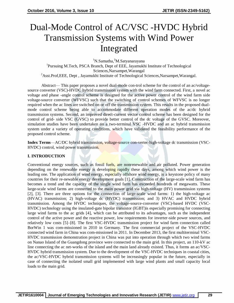
Fig. 1.Configuration of the wind farm grid connection via VSC-HVDC and ac hybrid transmission.
However, as far as the existing research is concerned, there is no VSC-HVDC control scheme that can adapt to the afore-mentioned two operation modes without switching control strategies.
Concerning the case of asynchronous connection with syn-chronous generators implemented in the sending-end of VSC-HVDC system, the active power-frequency adjusting scheme has been studied in [11]
where the VSC-HVDC active power is adjusted based on the frequency deviation of the sending-end bus.
Apparently, this control scheme cannot work in the situa-tion in that only DFIGs are installed in the sending end of the transmission system [12]. Another control scheme employed in this situation is realized through
setting the voltage amplitude and frequency of the ac bus of WFVSC to be constant. Con-sequently, the
WFVSC ac bus is controlled to simulate an in-finite bus, such that the active power transmitted by WFVSC
is controlled to follow the wind power variations. But this con-trol scheme can neither deal with the case of parallel operation nor the simplex operation mode of the ac/VSC-HVDC hybrid transmission system with
synchronous generators existing in the sending end of the transmission system.
Therefore, in the ac/VSC-HVDC hybrid transmission system, switching of the VSC-HVDC control schemes according to the operation mode of the ac/VSC-HVDC hybrid transmission system has to be
designed and this may greatly deteriorate the system reliability.
October 2016, Volume 3, Issue 10 JETIR (ISSN-2349-5162)
JETIR1610004 Journal of Emerging Technologies and Innovative Research (JETIR) www.jetir.org 31
In this paper, a more flexible VSC-HVDC control scheme called dual-mode control is proposed. A
new ac voltage and phase-angle control scheme is designed for the control of WFVSC and an improved
direct-current vector control scheme is proposed for the control of GVSC. More important, it re-quires no control scheme switching of WFVSC for the wind farm-grid connection via the ac/dc hybrid transmission
system. The proposed control scheme is tested in an ac/dc hybrid transmission simulation system under
various operation condi-tions. Simulation results are presented to show the validity and advantage of the control scheme.
This paper is organized as follows. Section II gives a brief introduction of the VSC-HVDC models. In Section III, the pro-posed control scheme for WFVSC is introduced in detail and analyzed. In Section IV,
the controller design for GVSC is in-troduced. Section V presented the simulation studies and con-clusions
are given in Section VI.
II. INTRODUCTION OF THE VSC-HVDC MODEL
A simplified system, where a wind farm is connected to the main grid through a VSC-HVDC transmission system and an ac transmission line that runs in parallel, is presented in Fig. 1. The
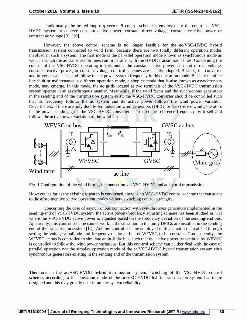
Fig. 2. WFVSC wind farm connection.
wind farm is composed of DFIGs. The WFVSC and the GVSC are connected to their ac buses via link
transformers. And the dc cable is adopted as the dc line.
The models of the DFIG and its control system have been in-troduced in detail in [13]–[16] and will
not be discussed here. The models of VSC-HVDC converters, that is, the WFVSC and the GVSC, are identical and are presented under the – refer-ence frame as follows:
where and are the equivalent resistance and inductance of the link transformer, respectively.
represents the capacitor installed on the VSC dc buses and is the direct voltage. , , , and are the -
axis and -axis voltage components of the station ac bus and of the VSC ac side, respectively. andrepresent the -axis and -axis components of the bridge switch variables. and are the -axis and -axis
current components which flow into the VSC. is the dc.
Concerning the control of GVSC, the constant dc voltage-control scheme is commonly adopted to
maintain the active power transmission balance. Meanwhile, constant power factor or constant ac voltage
control can be selected according to the requirement of the system reactive power balance.
October 2016, Volume 3, Issue 10 JETIR (ISSN-2349-5162)
JETIR1610004 Journal of Emerging Technologies and Innovative Research (JETIR) www.jetir.org 32
However, the control of WFVSC is quite different from the control of GVSC. If there is an ac
connection between the GVSC and the WFVSC, then the WFVSC usually selects con-stant ac voltage
magnitude and constant active power control. However, this conventional scheme cannot accommodate the asynchronous transmission mode.
A novel dual-mode control scheme is therefore proposed. The design of the control strategies for the WFVSC and GVSC is presented in detail in Sections III and IV.
III. DUAL-MODE CONTROL FOR THE WFVSC
A. Phase-Angle-Based Active Power Control
Concerning the WFVSC, a simplified structure is shown in Fig. 2, where and indicate the voltage
amplitude of the WFVSC ac bus and that of the VSC ac side, respectively.
Traditionally, the nested-loop – vector control is adopted where the axis is aligned with the VSC
ac bus voltage . The phase relationship between and is shown in Fig. 3.
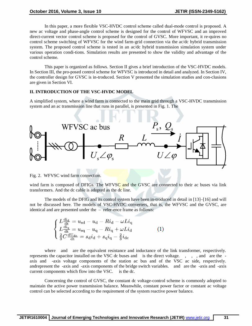
With the axis aligned with , the active power and reactive power represented in the synchronously rotating – frame are given by (2) with the power loss of the VSC neglected
Fig. 3. Voltage and phase relationship.Fig. 4. Illustration of the phase-angle adjustment.
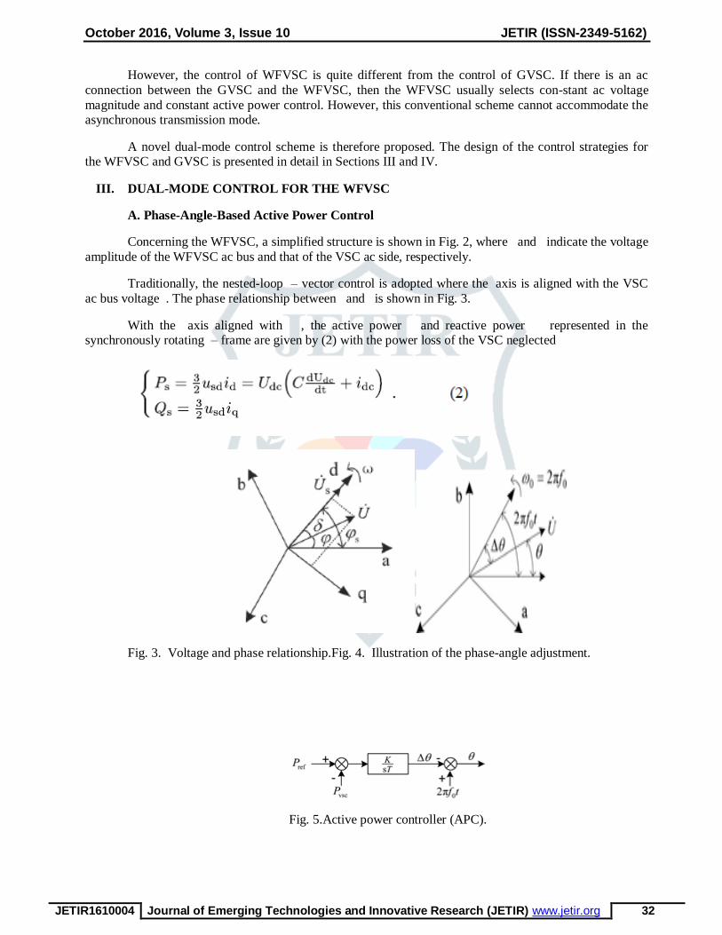
Fig. 5.Active power controller (APC).
October 2016, Volume 3, Issue 10 JETIR (ISSN-2349-5162)
JETIR1610004 Journal of Emerging Technologies and Innovative Research (JETIR) www.jetir.org 33
According to (2), if is constant, the control of Ps and Qscan be achieved by controlling id and
iqindependently, thatis, the d -axis current id and the q -axis current can be controllediqaccording to the error
of active power and reactive powertransferred to the dc system. Then, and are transformed tovoltage and according to (1).In the proposed dual-mode control scheme, direct control ofthe VSC ac-side voltage is
designed for the WFVSC. First, asynchronously rotating vector with frequency is generatedby the
controller's inner clock. This vector is taken as the rotatingreference vector. Define a static reference vector and thephase angle between the rotating reference vector and the staticreference vector is equal to . Then,
the active power transmittedvia WFVSC can be controlled by adjusting the phaseangle between and the
static reference vector as presentedin Fig. 4. Meanwhile, the adjustment angle between andthe rotating reference vector meets.
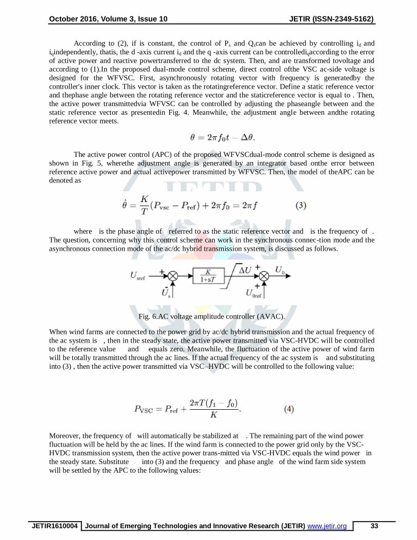
The active power control (APC) of the proposed WFVSCdual-mode control scheme is designed as
shown in Fig. 5, wherethe adjustment angle is generated by an integrator based onthe error between
reference active power and actual activepower transmitted by WFVSC. Then, the model of theAPC can be denoted as
where is the phase angle of referred to as the static reference vector and is the frequency of .
The question, concerning why this control scheme can work in the synchronous connec-tion mode and the
asynchronous connection mode of the ac/dc hybrid transmission system, is discussed as follows.
Fig. 6.AC voltage amplitude controller (AVAC).
When wind farms are connected to the power grid by ac/dc hybrid transmission and the actual frequency of
the ac system is , then in the steady state, the active power transmitted via VSC-HVDC will be controlled to the reference value and equals zero. Meanwhile, the fluctuation of the active power of wind farm
will be totally transmitted through the ac lines. If the actual frequency of the ac system is and substituting
into (3) , then the active power transmitted via VSC–HVDC will be controlled to the following value:
Moreover, the frequency of will automatically be stabilized at . The remaining part of the wind power
fluctuation will be held by the ac lines. If the wind farm is connected to the power grid only by the VSC-HVDC transmission system, then the active power trans-mitted via VSC-HVDC equals the wind power in
the steady state. Substitute into (3) and the frequency and phase angle of the wind farm side system
will be settled by the APC to the following values:

October 2016, Volume 3, Issue 10 JETIR (ISSN-2349-5162)
JETIR1610004 Journal of Emerging Technologies and Innovative Research (JETIR) www.jetir.org 34
From (5), when the wind power is greater than the reference value, the frequency of the sending-end system
will increase. Otherwise, the frequency of the sending-end system will de-crease. We could properly choose the value to restrain the operation frequency bias into an allowable range.According to the
aforementioned analysis, the proposed dual-mode control scheme can adapt to different operation modes of
the ac/VSC-HVDC transmission system without switching between different control strategies.
B. Voltage Amplitude Control of the WFVSC
Besides the active power control, the control of reactive power is another key issue. The voltage amplitude of the WFVSC ac bus should be controlled to an allowable level. In order to achieve this goal, the
amplitude of is controlled according to Fig. 6, where is the given reference value of , and is the
given reference value of .In the simulation tests of the VSC-HVDC system equipped with the WFVSC controller, we have observed postfault small active power oscillations at the wind farm side of the system
that lacks damping. The following small-signal analysis of the transfer function between and explains
the cause.In the system with wind farm connecting to the WFVSC shown in Fig. 2, denotes the phase
angle between and . In the synchronously rotating – frame with the axis being aligned with voltage , the instantaneous active power deviation is given by
Neglecting the variance of the voltage amplitude, then we have

October 2016, Volume 3, Issue 10 JETIR (ISSN-2349-5162)
JETIR1610004 Journal of Emerging Technologies and Innovative Research (JETIR) www.jetir.org 35
Substituting (8), (9), (10), and (13) into (7), the transfer func-tion between the active power and power angle is obtained
The dashed lines in Fig. 7(a) and (b) show the Bode diagrams of the transfer function (14). There is a
resonances point with frequency near 0.1 Hz which may be the cause of the active power oscillation
observed in the simulation tests.
In order to improve the performance of the control system, a negative current feedback link is
added to the voltage amplitude control loop which plays the damping function. This feedback block changes the voltage amplitude of the VSC side by the following equation:
where is a high-pass filter and its parameters are sett as K=0.5, = 50.
October 2016, Volume 3, Issue 10 JETIR (ISSN-2349-5162)
JETIR1610004 Journal of Emerging Technologies and Innovative Research (JETIR) www.jetir.org 36
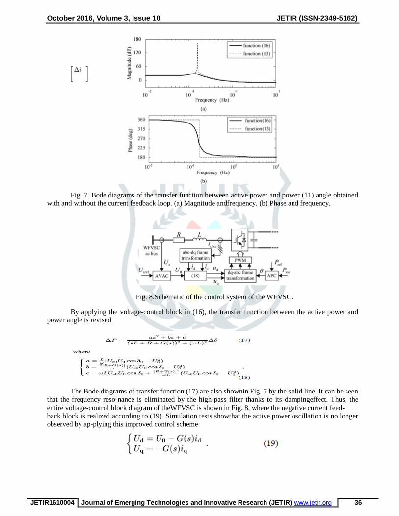
Fig. 7. Bode diagrams of the transfer function between active power and power (11) angle obtained
with and without the current feedback loop. (a) Magnitude andfrequency. (b) Phase and frequency.
Fig. 8.Schematic of the control system of the WFVSC.
By applying the voltage-control block in (16), the transfer function between the active power and
power angle is revised
The Bode diagrams of transfer function (17) are also shownin Fig. 7 by the solid line. It can be seen
that the frequency reso-nance is eliminated by the high-pass filter thanks to its dampingeffect. Thus, the
entire voltage-control block diagram of theWFVSC is shown in Fig. 8, where the negative current feed- back block is realized according to (19). Simulation tests showthat the active power oscillation is no longer
observed by ap-plying this improved control scheme
October 2016, Volume 3, Issue 10 JETIR (ISSN-2349-5162)
JETIR1610004 Journal of Emerging Technologies and Innovative Research (JETIR) www.jetir.org 37
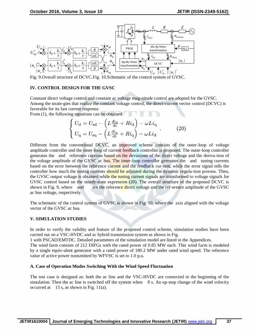
Fig. 9.Overall structure of DCVC.Fig. 10.Schematic of the control system of GVSC.
IV. CONTROL DESIGN FOR THE GVSC
Constant direct voltage control and constant ac voltage mag-nitude control are adopted for the GVSC.
Among the strate-gies that realize the constant voltage control, the direct-current vector control (DCVC) is
favorable for its fast current response. From (1), the following equations can be obtained:
Different from the conventional DCVC, an improved scheme consists of the outer-loop of voltage
amplitude controller and the inner-loop of current feedback controller is proposed. The outer-loop controller
generates the and reference currents based on the deviations of the direct voltage and the deriva-tion of the voltage amplitude of the GVSC ac bus. The inner-loop controller generates the and tuning currents
based on the error between the reference current and the feedback cur-rent, while the error signal tells the
controller how much the tuning currents should be adjusted during the dynamic regula-tion process. Then, the GVSC output voltage is obtained while the tuning current signals are transformed to voltage signals for
GVSC control based on the steady-state expression (20). The overall structure of the proposed DCVC is
shown in Fig. 9, where and are the reference direct voltage and the ref-erence amplitude of the GVSC
ac bus voltage, respectively.
The schematic of the control system of GVSC is shown in Fig. 10, where the axis aligned with the voltage
vector of the GVSC ac bus.
V. SIMULATION STUDIES
In order to verify the validity and feature of the proposed control scheme, simulation studies have been carried out on a VSC-HVDC and ac hybrid transmission system as shown in Fig.
1 with PSCAD/EMTDC. Detailed parameters of the simulation model are listed in the Appendices.
The wind farm consists of 212 DIFGs with the rated power of 0.85 MW each. This wind farm is modeled by a single equiv-alent generator with a rated power of 180.2 MW under rated wind speed. The reference
value of active power transmitted by WFVSC is set to 1.0 p.u.
A. Case of Operation Modes Switching With the Wind Speed Fluctuation
The test case is designed as: both the ac line and the VSC-HVDC are connected in the beginning of the
simulation. Then the ac line is switched off the system when 8 s. An up-step change of the wind velocity occurred at 13 s, as shown in Fig. 11(a).

October 2016, Volume 3, Issue 10 JETIR (ISSN-2349-5162)
JETIR1610004 Journal of Emerging Technologies and Innovative Research (JETIR) www.jetir.org 38
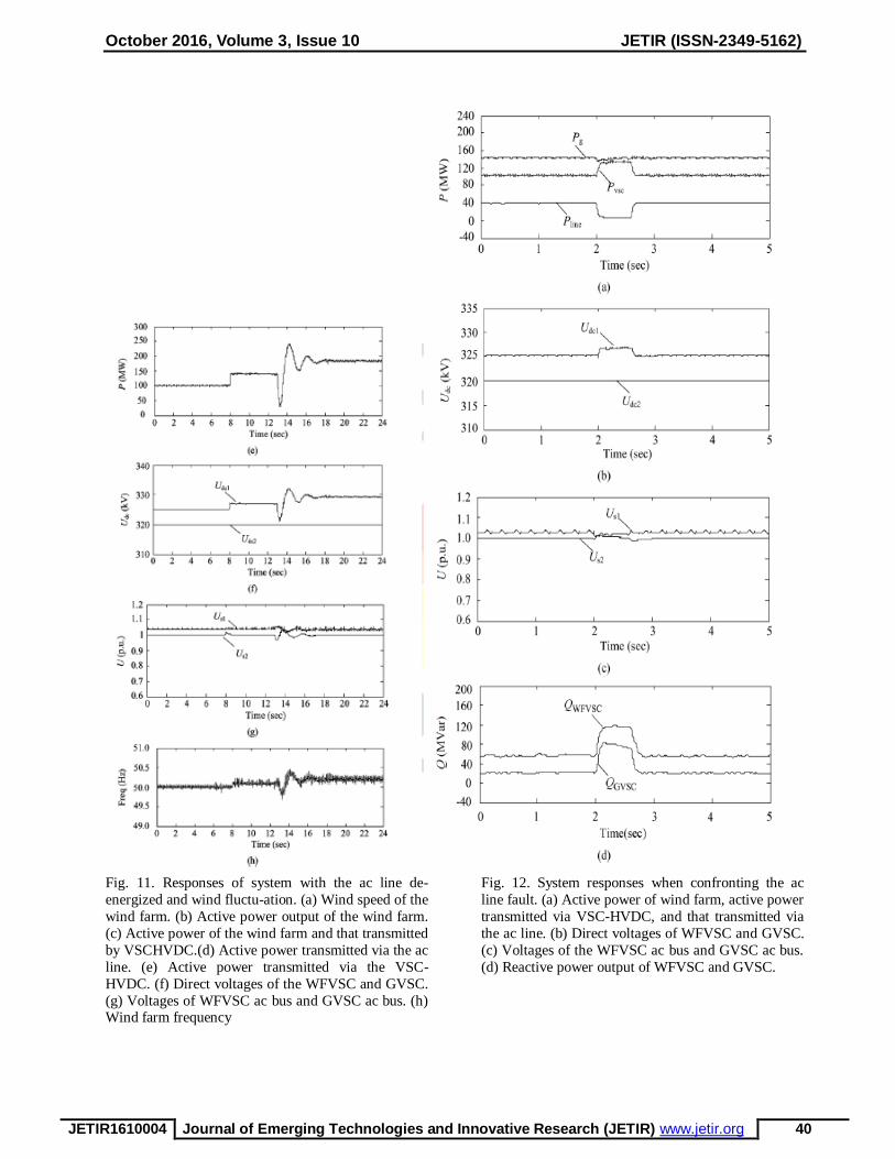
Fig. 11(b) – (h) shows the simulation results of different variables, where denotes the active power output
of the wind farm; represents the active power transmitted via the VSC-HVDC; and are the dc
voltage of the WFVSC and GVSC, respectively; and and denote the voltageof the WFVSC ac bus and GVSC ac bus, respectively.
At the normal ac/HVDC parallel operation mode, the refer-ence active power of the VSC-HVDC is set to be 100 MW. There are about 40 MW wind power transmitted through the ac line. When the ac line is
switched off at the time of 8 s, there is only the VSC-HVDC connection between the wind farm and the rest
of the system. From Fig. 11(c) and (h), one can find that the active power of the VSC-HVDC automatically increases to the value of wind plant output within 0.1 s when the VSC-HVDC is controlled with the
proposed control scheme. Meanwhile, the frequency of the WFVSC ac side increases a little. This matches
the analysis in (4) to (5) well.
When13 s, the wind speed steps up. From Fig. 11(b), adecrease of the wind farm active power can be
observed at the beginning of the disturbance. The active power of VSC-HVDC is just controlled to track the
active power of the wind farm such that the decrease of the active power of VSC-HVDC results in as depicted in Fig. 11(c) and (e). Essentially, the negative reaction of active power is caused by the MTP
control scheme of DFIG. When the wind speed steps up, the control system of DFIG increases the rotor
speed reference fast and leads to a short decreasing the active power output of the DFIG, which can be explained as follows. The dynamics of the rotor speedof the DFIG can be denoted as output of the wind
turbine after the wind speed steps. Therefore, if the active power decrease of wind farm is not allowed, the
maximum variation ratio of rotor speed .
. However, if the variation ratio of speed reference is larger than this value, the rotor speed will be regulated
to track the reference value and it results in the decrease of active power output of the DFIG. Thus, the
decreased active power after the wind speed increase is devoted to the acceleration of the rotor of DFIG.

October 2016, Volume 3, Issue 10 JETIR (ISSN-2349-5162)
JETIR1610004 Journal of Emerging Technologies and Innovative Research (JETIR) www.jetir.org 39
October 2016, Volume 3, Issue 10 JETIR (ISSN-2349-5162)
JETIR1610004 Journal of Emerging Technologies and Innovative Research (JETIR) www.jetir.org 40
Fig. 11. Responses of system with the ac line de-
energized and wind fluctu-ation. (a) Wind speed of the
wind farm. (b) Active power output of the wind farm.
(c) Active power of the wind farm and that transmitted
by VSCHVDC.(d) Active power transmitted via the ac
line. (e) Active power transmitted via the VSC-
HVDC. (f) Direct voltages of the WFVSC and GVSC.
(g) Voltages of WFVSC ac bus and GVSC ac bus. (h) Wind farm frequency
Fig. 12. System responses when confronting the ac
line fault. (a) Active power of wind farm, active power
transmitted via VSC-HVDC, and that transmitted via
the ac line. (b) Direct voltages of WFVSC and GVSC.
(c) Voltages of the WFVSC ac bus and GVSC ac bus.
(d) Reactive power output of WFVSC and GVSC.
October 2016, Volume 3, Issue 10 JETIR (ISSN-2349-5162)
JETIR1610004 Journal of Emerging Technologies and Innovative Research (JETIR) www.jetir.org 41
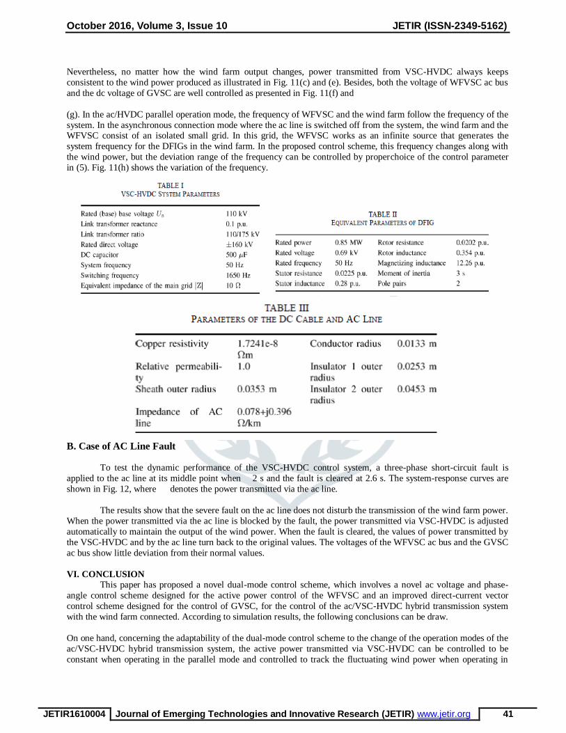
Nevertheless, no matter how the wind farm output changes, power transmitted from VSC-HVDC always keeps
consistent to the wind power produced as illustrated in Fig. 11(c) and (e). Besides, both the voltage of WFVSC ac bus
and the dc voltage of GVSC are well controlled as presented in Fig. 11(f) and
(g). In the ac/HVDC parallel operation mode, the frequency of WFVSC and the wind farm follow the frequency of the
system. In the asynchronous connection mode where the ac line is switched off from the system, the wind farm and the WFVSC consist of an isolated small grid. In this grid, the WFVSC works as an infinite source that generates the
system frequency for the DFIGs in the wind farm. In the proposed control scheme, this frequency changes along with
the wind power, but the deviation range of the frequency can be controlled by properchoice of the control parameter
in (5). Fig. 11(h) shows the variation of the frequency.
B. Case of AC Line Fault
To test the dynamic performance of the VSC-HVDC control system, a three-phase short-circuit fault is
applied to the ac line at its middle point when 2 s and the fault is cleared at 2.6 s. The system-response curves are
shown in Fig. 12, where denotes the power transmitted via the ac line.
The results show that the severe fault on the ac line does not disturb the transmission of the wind farm power.
When the power transmitted via the ac line is blocked by the fault, the power transmitted via VSC-HVDC is adjusted
automatically to maintain the output of the wind power. When the fault is cleared, the values of power transmitted by
the VSC-HVDC and by the ac line turn back to the original values. The voltages of the WFVSC ac bus and the GVSC
ac bus show little deviation from their normal values.
VI. CONCLUSION
This paper has proposed a novel dual-mode control scheme, which involves a novel ac voltage and phase-
angle control scheme designed for the active power control of the WFVSC and an improved direct-current vector
control scheme designed for the control of GVSC, for the control of the ac/VSC-HVDC hybrid transmission system
with the wind farm connected. According to simulation results, the following conclusions can be draw.
On one hand, concerning the adaptability of the dual-mode control scheme to the change of the operation modes of the
ac/VSC-HVDC hybrid transmission system, the active power transmitted via VSC-HVDC can be controlled to be
constant when operating in the parallel mode and controlled to track the fluctuating wind power when operating in

October 2016, Volume 3, Issue 10 JETIR (ISSN-2349-5162)
JETIR1610004 Journal of Emerging Technologies and Innovative Research (JETIR) www.jetir.org 42
asynchronous mode. Meanwhile, the frequency of the WFVSC shows precise tracking of the grid frequency.
Moreover, the dc voltage of the GVSC and WFVSC and the voltage of WFVSC and GVSC ac bus have presented
little oscillation during the operation mode switching. Specially, when two asynchronous systems are con-nected by
the VSC-HVDC, the WFVSC can be automatically controlled to resemble an ac voltage source and settle the fre-
quency and amplitude of its ac bus voltage, which can provide a voltage reference for the wind farm.
On the other hand, the dual-mode control scheme has pre-sented strong robustness to the system fault. Therefore, only
slight fluctuation can be observed from the active power of the wind farm, active power transmitted by VSC-HVDC,
directvoltage of WFVSC and GVSC, and the voltage of the WFVSC and GVSC ac bus despite the three-phase short-
circuit fault occurring on the ac transmission line.
APPENDIX
Parameters of the VSC-HVDC System: For system param-eters, see Table I.Parameters of the Wind Farms
Equipped With DFIG: The wind farm is modeled with an equivalent DFIG of 180.2 MW. The wind farm is connected
to the WFVSC ac bus by two-stage transformers called T1-1 and T1-2, respectively. The transfor-mation ratio of T1-1
is 0.69 kV/35 kV and the one of T1-2 is 35 kV/110 kV. Table II lists the equivalent parameters of the DFIG.
Parameters of the DC Cable and AC Line: The dc cable and ac line are 100 km long. Table III lists the dc cable param-
eters and ac line parameters.
REFERENCES
[1]A. Purvins, A. Zubaryeva, M. Llorente, E. Tzimas, and A. Mercier, ―Challenges and options for a large wind power
uptake by the european electricity system,‖ Appl. Energy, vol. 88, no. 5, pp. 1461–1469, 2011.
[2]L. Y. Zhang, T. L. Ye, Y. Z. Xin, and G. F. Fan, ―Problems and mea-sures of power grid accommodating large scale wind power,‖ in Proc. Chinese Soc. Elect.Eng., Sep. 2010, vol. 30, pp. 1–9, 25.
[3]Z. X. Wang, C. Jiang, Q. Ai, and C. Wang, ―The key technology of off-shore wind farm and its new development in
China,‖ Renew. Sustain. Energy Rev., vol. 13, no. 1, pp. 216–222, 2009.
[4]P. Bresesti, W. L. Kling, R. L. Hendriks, and R. Vailati, ―HVDC connection of offshore wind farms to the
transmission system,‖ IEEE Trans. Energy Convers., vol. 22, no. 1, pp. 37–43, Mar. 2007.
[5]N. Flourentzou, V. G. Agelidis, and G. D. Demetriades, ―VSC-based HVDC power transmission systems: An
overview,‖ IEEE Trans. Power Electron., vol. 24, no. 3, pp. 592–602, Mar. 2009.
[6]S. J. Shao and V. G. Agelidis, ―Review of DC system technologies for large scale integration of wind energy
systems with electricity grids,‖ Energies, vol. 3, no. 6, pp. 1303–1319, 2010.
[7]B. Van Eeckhout, D. Van Hertem, M. Reza, K. Srivastava, and R. Bel-mans, ―Economic comparison of VSC
HVDC and HVAC as transmis-sion system for a 300 MW offshore wind farm,‖ Eur. Trans. Elect. Power, vol. 20, no.
5, pp. 661–671, 2010.
[8]O. Gomis-Bellmunt, J. Liang, J. Ekanayake, and N. Jenkins, ―Voltage-current characteristics of multiterminal
HVDC-VSC for offshore wind farms,‖ Elect. Power Syst. Res., vol. 81, no. 2, pp. 440–450, 2011.
[9]S. Li, T. A. Haskew, and L. Xu, ―Control of HVDC light system using conventional and direct current vector
control approaches,‖ IEEE Trans. Power Electron., vol. 25, no. 12, pp. 3106–3118, Dec. 2010.
[10]. L. Z. W. G. Wang, ―Improved predictive direct-power-control of offshore VSC-HVDC converter without PLL scheme,‖ Int. Rev. Elect. Eng., vol. 7, no. 2, pp. 3709–3716, 2012.
[11]H. F. Latorre, M. Ghandhari, and L. Söder, ―Active and reactive power control of a VSC-HVDC,‖ Elect. Power
Syst. Res., vol. 78, no. 10, pp. 1756–1763, 2008.
[12]M. Liserre, R. Crdenas, and M. Molinas, ―Overview of multi-MW wind turbines and wind parks,‖ IEEE Trans.
Ind. Electron., vol. 58, no. 4, pp. 1081–1092, Apr. 2011.

October 2016, Volume 3, Issue 10 JETIR (ISSN-2349-5162)
JETIR1610004 Journal of Emerging Technologies and Innovative Research (JETIR) www.jetir.org 43
[13]H. Li, C. Yang, B. Zhao, H. Wang, and Z. Chen, ―Aggregated models and transient performances of a mixed wind
farm with different wind turbine generator systems,‖ Elect. Power Syst. Res., vol. 92, pp. 1–10, 2012.
[14]M. Tazil, V. Kumar, R. Bansal, S. Kong, Z. Dong, W. Freitas, and H. Mathur, ―Three-phase doubly fed induction
generators: An overview,‖ IET Elect. Power Appl., vol. 4, no. 2, pp. 75–89, 2010.
[15]J. b. Hu, Y. k.He, and H. Nian, ―Enhanced control of DFIG-used back-to-back PWM VSC under unbalanced grid
voltage conditions,‖ J. Zhejiang Univ. Sci.A, vol. 8, no. 8, pp. 1330–1339, 2007.
[16]A. M. Kassem, K. M. Hasaneen, and A. M. Yousef, ―Dynamic mod-eling and robust power control of DFIG
driven by wind turbine at infi-nite grid,‖ Int. J. Elect.Power Energy Syst., vol. 44, no. 1, pp. 375–382, 2013.