fabrication erection and installation procedure for piping
DESCRIPTION
This document covers the sequence of activities for Fabrication, Erection and Installation procedure for Metallic Piping (Carbon Steels, Alloy Steels, Stainless Steels, Nickel Alloys) systems and to ensure the compliance to the above activities with the contractual applications and HSE requirementsTRANSCRIPT
Document No. Doc. Type Discipline System JOB No.
SA-JER-XXXXXX-XXXX-XXXXXX
PRC CNS3000235453
FABRICATION, ERECTION AND INSTALLATION
PROCEDURE FOR PIPING
Revision No.
Remarks Issued Date Return Date
00 ISSUED FOR REVIEW 20-APR-2010 20-MAY-201001 ISSUED FOR ACCEPTANCE 13-JUN-2010 21-JUN-201002 ISSUED FOR CONSTRUCTION 28-JUN-2010
Prepared By Checked By Approved By Issued By
PORT TANK FARM PACKAGE 9
IMPORTANT:
No part of this publication may be reproduced, stored in a retrieval system, or transmitted in any form, or by means of electronic, mechanical, photocopying, recording, or otherwise, without the written permission of Rotary Engineering Limited.
Revision History
Revision Revision date Page Scope of Revision
00 20-APR-2010 ALL ISSUED FOR REVIEW01 25-MAY-2010 3 REVISED THE INDEX
01 25-MAY-2010 4 SPECIFIED THE SCOPE
01 25-MAY-2010 9ADDED MATERIAL TRACABILITY & ISOMETRIC MARK- UP
01 25-MAY-2010 20 ADDED IDENTIFICATION AND MARKING
01 25-MAY-2010 23 ADDED FLUSHING, REINSTATEMENT
01 25-MAY-2010 24 AADDED EQUIPMENT AND RESOURCES
01 25-MAY-2010 28 NOTE ON JSA 2.3- MATERIAL TRANSPORTATION
01 25-MAY-2010 35 ATTACHED ALL INSPECTION FORMS
01 13-JUN-2010 35 ISSUED FOR ACCEPTANCE
02 21-JUN-2010 35 ISSUED FOR CONSTRUCTION
Doc No: Title: Page 2 of 38SA-JER-XXXXXX-XXXX-XXXXXX FABRICATION, ERECTION AND INSTALLATION
PROCEDURE FOR PIPING
PORT TANK FARM PACKAGE 9
TABLE OF CONTENT
1 SCOPE………………………………………………………………………………… 4
2 DEFINITION…………………………………………………………………………… 4
3 REFERENCE………………………………………………………………………….. 4
4 RESPONSIBILITY……………………………………………………………………. 6
5 PROCEDURE………………………………………………………………………….. 7
6 PRODUCTS AND MATERIALS…………………………………………………….. 7
7 PRE-FABRICATION………………………………………………………………….. 9
8 PIPING ERECTION…………………………………………………………………… 13
9 INSTALLATION OF UNDERGROUND PIPING…………………………………... 15
10 DIMESIONAL CHECKING…………………………………………………………… 16
11 WELDING………………………………………………………………………………. 16
12 GALVANIZING PAINTING AND COATING……………………………………….. 19
13 IDENTIFICATION AND MARKING ………………………………………………… 20
14 QUALITY ASSURANCE AND QUALITY CONTROL…………………………… 20
15 PRESSURE TESTING………………………………………………………………... 22
16 FLUSHING……….………………………………………………………..…………... 23
17 REINSTATEMENT ….………………………………………………………………... 23
18 EQUIPMENT AND RESOURCES…………………………………………………... 24
19 HEALTH SAFETY AND ENVIRONMENT………………………………………….. 24
20 ATTACHMENT 1 (JOB SAFETY ANALYSIS)…………………………………….. 26
21 ATTACHMENT 2 (WORK FLOW- PIPING PRE- FABRICATION)……………… 32
22 ATTACHMENT 3 (WORK FLOW- PIPING ERECTION)…………………………. 33
23 ATTACHMENT 4 (TYPICAL LIFTING INSTALLATION PLAN)………………… 34
24 ATTACHMENT 5 (INSPECTION FORMS)…………………………………………. 35
Doc No: Title: Page 3 of 38SA-JER-XXXXXX-XXXX-XXXXXX FABRICATION, ERECTION AND INSTALLATION
PROCEDURE FOR PIPING
PORT TANK FARM PACKAGE 9
1. SCOPE
This document covers the sequence of activities for Fabrication, Erection and Installation
procedure for Metallic Piping (Carbon Steels, Alloy Steels, Stainless Steels, Nickel Alloys)
systems and to ensure the compliance to the above activities with the contractual applications
and HSE requirements in PORT TANK FARM PACKAGE 9 Project.
2. DEFINITIONS
2.1 COMPANY –
2.2 CONTRACTOR –
2.3 DDDD
2.4 DDDD
2.5 D
2.6 D
2.7 D
2.8 D
2.9 D
2.10 D
2.11 DD
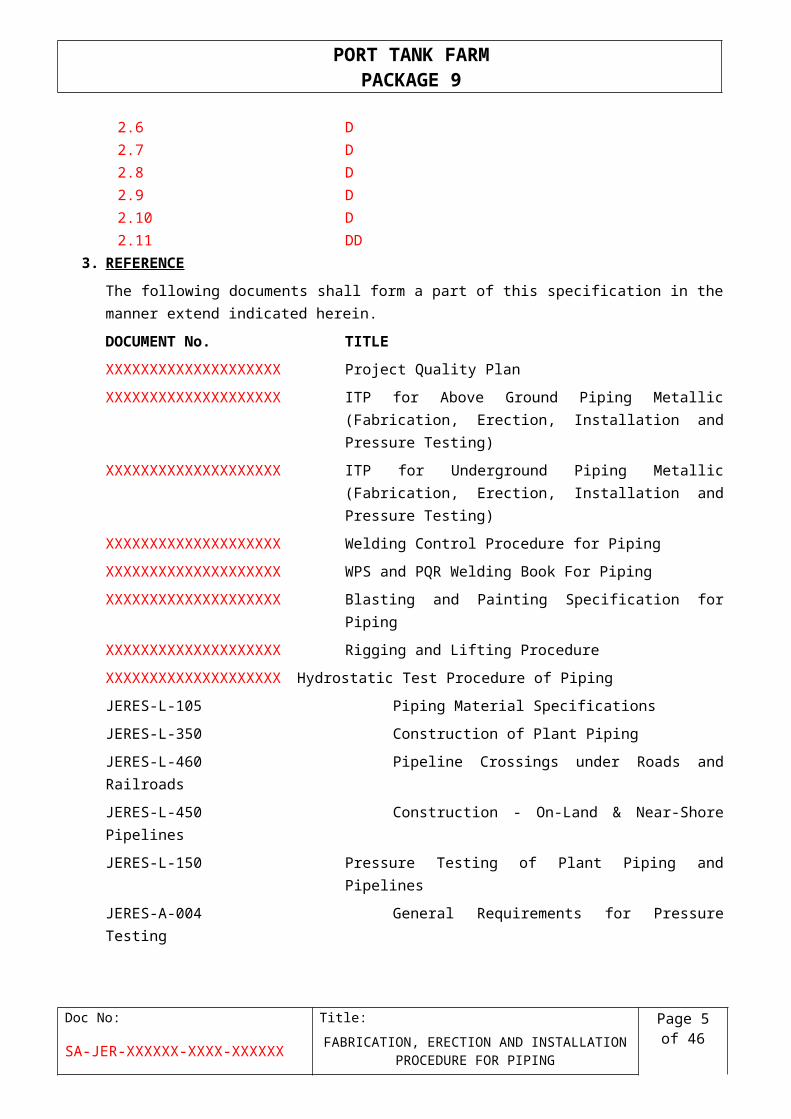
3. REFERENCE
The following documents shall form a part of this specification in the manner extend indicated
herein.
DOCUMENT No. TITLE
XXXXXXXXXXXXXXXXXXXX Project Quality Plan
XXXXXXXXXXXXXXXXXXXX ITP for Above Ground Piping Metallic (Fabrication,
Erection, Installation and Pressure Testing)
XXXXXXXXXXXXXXXXXXXX ITP for Underground Piping Metallic (Fabrication, Erection,
Installation and Pressure Testing)
XXXXXXXXXXXXXXXXXXXX Welding Control Procedure for Piping
XXXXXXXXXXXXXXXXXXXX WPS and PQR Welding Book For Piping
XXXXXXXXXXXXXXXXXXXX Blasting and Painting Specification for Piping
XXXXXXXXXXXXXXXXXXXX Rigging and Lifting Procedure
XXXXXXXXXXXXXXXXXXXX Hydrostatic Test Procedure of Piping
JERES-L-105 Piping Material Specifications
JERES-L-350 Construction of Plant Piping
JERES-L-460 Pipeline Crossings under Roads and Railroads
JERES-L-450 Construction - On-Land & Near-Shore Pipelines
JERES-L-150 Pressure Testing of Plant Piping and Pipelines
Doc No: Title: Page 4 of 38SA-JER-XXXXXX-XXXX-XXXXXX FABRICATION, ERECTION AND INSTALLATION
PROCEDURE FOR PIPING
PORT TANK FARM PACKAGE 9
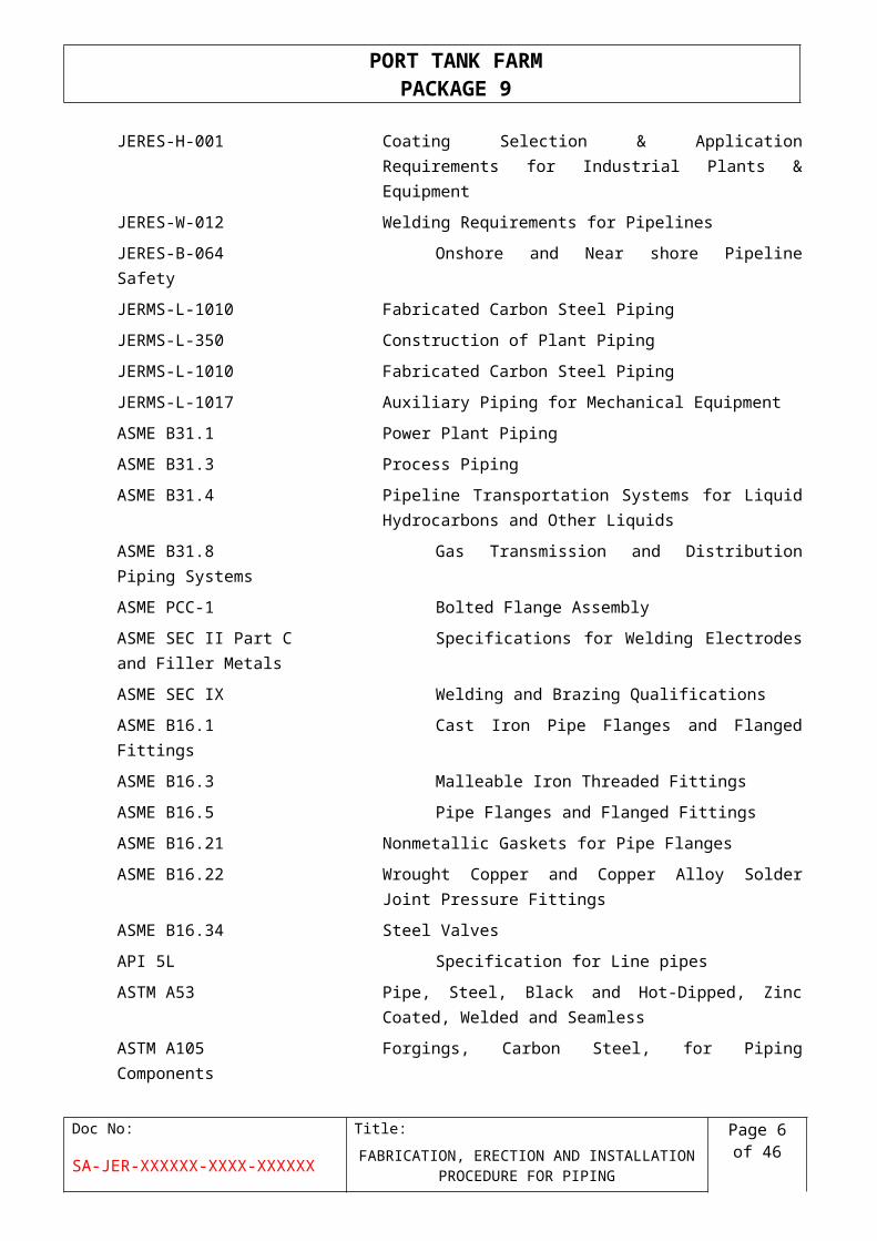
JERES-A-004 General Requirements for Pressure Testing
JERES-H-001 Coating Selection & Application Requirements for
Industrial Plants & Equipment
JERES-W-012 Welding Requirements for Pipelines
JERES-B-064 Onshore and Near shore Pipeline Safety
JERMS-L-1010 Fabricated Carbon Steel Piping
JERMS-L-350 Construction of Plant Piping
JERMS-L-1010 Fabricated Carbon Steel Piping
JERMS-L-1017 Auxiliary Piping for Mechanical Equipment
ASME B31.1 Power Plant Piping
ASME B31.3 Process Piping
ASME B31.4 Pipeline Transportation Systems for Liquid Hydrocarbons
and Other Liquids
ASME B31.8 Gas Transmission and Distribution Piping Systems
ASME PCC-1 Bolted Flange Assembly
ASME SEC II Part C Specifications for Welding Electrodes and Filler Metals
ASME SEC IX Welding and Brazing Qualifications
ASME B16.1 Cast Iron Pipe Flanges and Flanged Fittings
ASME B16.3 Malleable Iron Threaded Fittings
ASME B16.5 Pipe Flanges and Flanged Fittings
ASME B16.21 Nonmetallic Gaskets for Pipe Flanges
ASME B16.22 Wrought Copper and Copper Alloy Solder Joint Pressure
Fittings
ASME B16.34 Steel Valves
API 5L Specification for Line pipes
ASTM A53 Pipe, Steel, Black and Hot-Dipped, Zinc Coated, Welded
and Seamless
ASTM A105 Forgings, Carbon Steel, for Piping Components
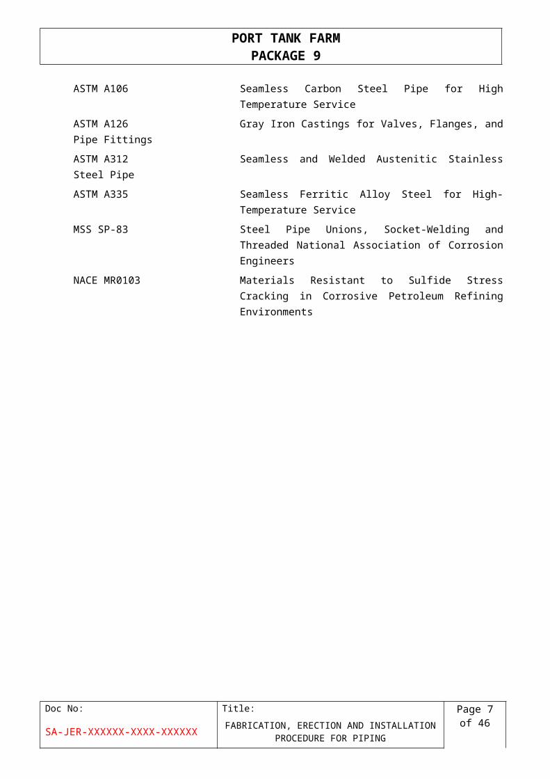
ASTM A106 Seamless Carbon Steel Pipe for High Temperature
Service
ASTM A126 Gray Iron Castings for Valves, Flanges, and Pipe Fittings
ASTM A312 Seamless and Welded Austenitic Stainless Steel Pipe
ASTM A335 Seamless Ferritic Alloy Steel for High-Temperature
Service
Doc No: Title: Page 5 of 38SA-JER-XXXXXX-XXXX-XXXXXX FABRICATION, ERECTION AND INSTALLATION
PROCEDURE FOR PIPING
PORT TANK FARM PACKAGE 9
MSS SP-83 Steel Pipe Unions, Socket-Welding and Threaded
National Association of Corrosion Engineers
NACE MR0103 Materials Resistant to Sulfide Stress Cracking in Corrosive
Petroleum Refining Environments
Doc No: Title: Page 6 of 38SA-JER-XXXXXX-XXXX-XXXXXX FABRICATION, ERECTION AND INSTALLATION
PROCEDURE FOR PIPING
PORT TANK FARM PACKAGE 9
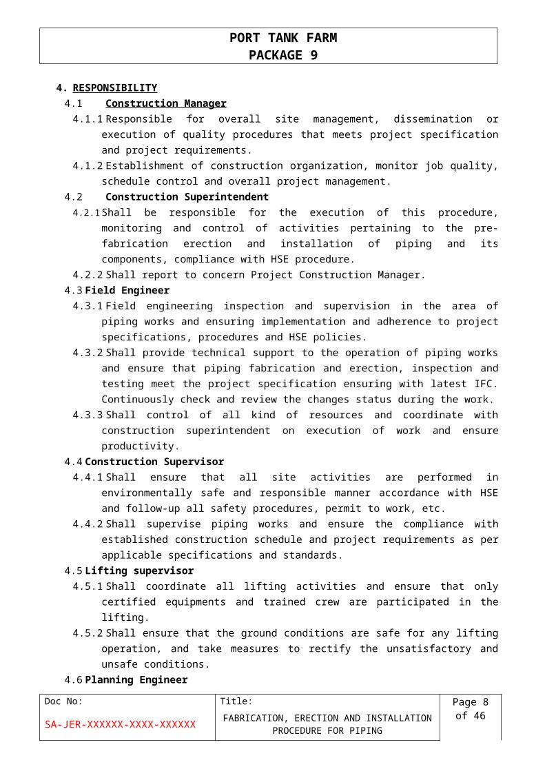
4. RESPONSIBILITY
4.1 Construction Manager
4.1.1 Responsible for overall site management, dissemination or execution of quality
procedures that meets project specification and project requirements.
4.1.2 Establishment of construction organization, monitor job quality, schedule control and
overall project management.
4.2 Construction Superintendent
4.2.1 Shall be responsible for the execution of this procedure, monitoring and control of
activities pertaining to the pre-fabrication erection and installation of piping and its
components, compliance with HSE procedure.
4.2.2 Shall report to concern Project Construction Manager.
4.3 Field Engineer
4.3.1 Field engineering inspection and supervision in the area of piping works and ensuring
implementation and adherence to project specifications, procedures and HSE policies.
4.3.2 Shall provide technical support to the operation of piping works and ensure that piping
fabrication and erection, inspection and testing meet the project specification ensuring
with latest IFC. Continuously check and review the changes status during the work.
4.3.3 Shall control of all kind of resources and coordinate with construction superintendent on
execution of work and ensure productivity.
4.4 Construction Supervisor
4.4.1 Shall ensure that all site activities are performed in environmentally safe and responsible
manner accordance with HSE and follow-up all safety procedures, permit to work, etc.
4.4.2 Shall supervise piping works and ensure the compliance with established construction
schedule and project requirements as per applicable specifications and standards.
4.5 Lifting supervisor
4.5.1 Shall coordinate all lifting activities and ensure that only certified equipments and trained
crew are participated in the lifting.
4.5.2 Shall ensure that the ground conditions are safe for any lifting operation, and take
measures to rectify the unsatisfactory and unsafe conditions.
4.6 Planning Engineer
4.6.1 Shall be responsible for monitoring progress throughout the construction process and
comparing this with the projected schedule of work with introducing appropriate logistics
solutions and resources.
4.6.2 Shall be responsible for day to day micro planning in coordination with field engineer and
construction superintendent and report activities to Project Control Manger.
4.7 QA/QC Inspector
4.7.1 Shall be responsible for inspection on production of pipes ,fittings and spools to ensure
the procedures are being followed in order to ensure that quality standards being
achieved as per Project procedures, requirements and specifications.
4.7.2 Shall be responsible for maintenance of NDT records & Project documentation.
Doc No: Title: Page 7 of 38SA-JER-XXXXXX-XXXX-XXXXXX FABRICATION, ERECTION AND INSTALLATION
PROCEDURE FOR PIPING
PORT TANK FARM PACKAGE 9
4.8 HSE Team
4.8.1 Shall be responsible for the implementation of the HSE procedures before and during the
execution of Piping fabrication and erection.
4.8.2 Shall be responsible for check for any unsafe conditions on the working areas and liaise
with field Supervisor ensuring that the work is carried out as per approved Project safety
plan and procedure.
5. PROCEDURE
5.1 Ensure that the document received bear the stamp “Issued for Construction” and are of
latest revision.
5.2 The documents submitted/referred with this method statement shall be considered as an
integral part of this method statement and shall be read in conjunction with the same.
5.3 The engineering drawings and documents received shall be clearly understood to find out
the service, material specification, size, thickness, QA/QC requirements, pipe routing
quantity etc. line wise and area wise.
5.4 Make sure that all the Quality control and Pre-Construction formalities, approvals, and
preparations are done sufficiently in advance to start the construction activity as per the
schedule.
5.5 A checklist of all requirements shall be made internally to avoid any omission of them.
6. PRODUCTS AND MATERIALS
6.1 General Requirements
6.1.1 Proper HSE material handling procedure must be followed during material receiving,
storing and delivery.
6.1.2 All materials shall be conformed to the IFC drawing with relevant material specifications
before receiving/ordering.
6.1.3 Separate area shall be assigned for the storage of different piping materials. Pipes shall
be stored in open area resting on wooden sleepers, fittings, bolts, nuts, and gaskets shall
be stored in shelved containers. Storage and issue procedure of piping materials shall be
in time with the requirements.
6.1.4 Handling and transportation of piping materials shall be done with utmost care to avoid
any damage.
6.1.5 QC inspector shall conduct visual inspections, check color code, material certificates or
manufacturer’s test reports (including size, wall thickness, rating, material code, heat no,
quantity). (Ref: Procedure for Material Quality Control and Material Traceability- SA-JER-
XXXXXX-XXXX-XXXXXX).
6.2 Material Receiving, Storing and Delivery
The following procedure shall be followed for receiving, storing and delivery of all the materials,
Doc No: Title: Page 8 of 38SA-JER-XXXXXX-XXXX-XXXXXX FABRICATION, ERECTION AND INSTALLATION
PROCEDURE FOR PIPING

PORT TANK FARM PACKAGE 9
6.2.1 Warehouse superintendent shall be responsible for delivering all materials and
documentation to the job site in good condition. All materials and documentation will be
inspected immediately upon receipt by CONTRACTOR QC Inspector to determine that
all items included in the Bill of Materials have been supplied, to assure that all
documentation has been received and to check for any damage.
6.2.2 All materials shall be requested or received as per pre-fabrication or erection sequence
or site requirements as per the CONTRACTOR Master Schedule which is agreed &
approved by the COMPANY
6.2.3 The receiving materials or equipment found defective or presenting non-conformance
that shall be clearly marked out and shall be returned to corresponding authority.
6.2.4 Material shall be stored at defined locations based on material classification. Carbon
Steels, Alloyed Steels, Stainless Steels, non-ferrous material etc...
6.2.5 Large-sized fittings, flanges and valves shall be stored on wooden pallets and no
material is allowed to rest or store directly on ground at all time.
6.2.6 All small-sized fittings, flanges and valves, and all of gaskets shall be stored on
racks/shelves.
6.2.7 All bolts, washers and nuts shall be packaged and delivered in rigid, weatherproof
containers.
6.2.8 Flanged openings shall be fitted with plywood covers or fitted PVC flange covers,
threaded openings are to be closed with plugs or similar, pipe openings shall be cover
with end cap or plastic cover to prevent accumulation of dust or foreign materials.
6.2.9 Ensure the material is secured properly so that it does not fall, roll or move from its
storage position. Pipes will be supported at bottom with kegs/ wooden blocks at least at
three points and choked with wedges.
6.2.10Materials stored in open areas will be barricaded and indicate the type of material and
the hazard it poses, if any.
6.2.11Coated pipe shall be handled at all times in a manner that prevents damage to the pipe
walls (shall not be rolled or dragged on the ground), beveled ends and to the coating and
open end should be covered with polyethylene sheeting.
6.2.12Sling shall be nylon or equivalent; steel cables shall not be used.
6.2.13Each length of pipe shall be examined to make sure it is free from internal obstructions
and shall be air blown to remove dust and sand immediately prior to erection or welding.
6.2.14Materials released for the specific ISO shall be used for the specific ISO and can not be
used wherever.
6.2.15Scrap materials shall send back to LOD with punched line number, heat no and material
code
6.2.16Material shall be received, stored, and delivered under code Material Receiving,
Handling, Storing and Deliver (Ref. SA-JER-XXXXXX-XXXX-XXXXXX), Field Material
Control Plan (Ref. SA-JER-XXXXXX-XXXX-XXXXXX).
6.3 Material Traceability
Doc No: Title: Page 9 of 38SA-JER-XXXXXX-XXXX-XXXXXX FABRICATION, ERECTION AND INSTALLATION
PROCEDURE FOR PIPING
PORT TANK FARM PACKAGE 9
6.3.1 Identification code or File number shall be clearly marked on each plate, pipe and nozzle
item by the Material Controller / Storekeeper.
6.3.2 QC personnel shall monitor the transferring of heat number for Stainless Steel material.
6.3.3 To prevent loss of traceability during paint / coating process, QC personnel shall make
sure that the identification number is transferred to the QC record prior to blasting.
6.3.4 Piece marks and weld identification number shall be marked on each pipe / plate by
suitable paint which shall be compatible with the base material to be marked and
recorded on the relevant documents.
6.3.5 The heat number shall be transferred before the plate or pipe is cut.
6.3.6 Color-coding shall be applied for easy identification to permit quick material handling /
segregation and visual check / monitoring during construction phrases.
6.3.7 Material Quality Control Material Traceability shall be reference with SA-JER-XXXXXX-
XXXX-XXXXXX.
7. PRE-FABRICATION
7.1 Checklist for Pre-Fabrication of Piping
7.1.1 Approval of Method Statement, Quality Plan and ITP
7.1.2 Approval of WPS covering all the material specifications.
7.1.3 Welder qualification list review and approval.
7.1.4 All the required Engineering drawings and documents are received in time.
7.1.5 All personnel and procedures for NDT, PWHT are approved.
7.1.6 Spool drawings marking field and shop weld joints shall be prepared, numbered and
reviewed.
7.1.7 All tools, equipment and temporary items like pipe stands; pipe clamps etc. are ready in
sufficient quantities.
7.1.8 Consumables shall arrange in sufficient quantities as per the WPS.
7.1.9 Welding data base set up prior start of welding activities.
7.1.10Procedure for handling and storage of consumables shall be issued.
7.2 Isometric Mark-Up
7.2.1 All lines shall be clearly marked to easily identify the flow direction, service, line
designation number, size, class and specification.
7.2.2 The isometric drawing shall be used as a weld mark-up format.
7.2.3 The weld map shall be unique and separate for each line, system, component or
assembly number.
7.2.4 The line diagram shall include weld location, weld numbers, tie point location, piece
numbers and weld type, including: Field weld, shop Weld, tie point, butt joint, socket
joint, fillet weld.
Doc No: Title: Page 10 of 38
SA-JER-XXXXXX-XXXX-XXXXXX FABRICATION, ERECTION AND INSTALLATION PROCEDURE FOR PIPING

PORT TANK FARM PACKAGE 9
7.2.5 Straight run of pipe shall contain the minimum number of welds. The use of off-cuts in
straight run shall be avoided.
7.2.6 Joints before connection to the rotating equipment nozzles and its break up point shall
be field measured and welded to avoid external loading on the equipment connection
7.2.7 Piping butt welds shall be spaced a minimum of 50 mm or four times the thinnest wall
thickness measuring between the heat affected zones, whichever is greatest.
7.2.8 Care shall be taken to ensure that the longitudinal welds clear branch connections.
7.2.9 Weld numbering methodology shall contain: a sequential number, a repair sequence
number when applicable.
7.2.10Length, height and width of the spools shall be within the limits of road transport and
erection possibility, unless specifically requested.
7.2.11Modification of pipe joint shall be done at site if necessary to avoid interference in
accordance with the engineering clarification.
7.3 Cutting and Beveling
7.3.1 All pipes and fittings shall be cleaned before prefabrication by air blowing. In addition, for
large diameters pipe rag cleaning should be conducted if found practical.
7.3.2 Proper Safety procedure shall follow before starting the job.
7.3.3 Pre-fabrication of Stainless Steel and alloy piping shall be done in separate fabrication
bays.
7.3.4 Marking should be done as per Isometric spool number measurement.
7.3.5 Cutting of pipes, fittings and edge preparation as per the drawing and WPS.
7.3.6 Based on spool breakdown of piping isometrics, pipe length shall be cut. Extra length for
pipe shall be provided in spools for field adjustment.
7.3.7 Pipes shall cut using Oxy-acetylene cutting or plasma as per project requirement. Flame
cutting of Stainless Steel is not allowed. Stainless steel shall be cut with Stainless Steel
cutting disc. The edge cleaning and beveling shall be done using abrasive grinding disc.
7.3.8 The edges to be welded shall be prepared to meet the joint design requirements by any
of the following method recommended:
Carbon Steel (C.S)
Gas cutting, Machining or grinding methods shall be used. After gas cutting, oxides shall
be smoothened / removed by chipping and grinding.
Alloy Steel
Gas cutting, Machining or grinding methods shall be used. After gas cutting, machining
or grinding shall be carried out on the cut surface.
Stainless Steels (S.S), Nickel Alloys
Doc No: Title: Page 11 of 38
SA-JER-XXXXXX-XXXX-XXXXXX FABRICATION, ERECTION AND INSTALLATION PROCEDURE FOR PIPING
PORT TANK FARM PACKAGE 9
Machining or grinding methods shall be used. After cutting, cut surface shall be
machined or ground smooth.
7.3.9 Where, spectacle plate is required by the ISO drawing, the fabricator shall drill a tap and
install jack screw for flanges.
7.3.10Heat numbers has to be transferred to pipes after cutting; remaining material must keep
allocated locations with all marked specifications.
7.3.11Electrical power source should be used for hand machine during fabrication.
7.4 Fit- Up and Track Welding
7.4.1 Fit-up assembly and joint alignment shall be carried out, by using couplers or clamps. All
the required pipe holding work benches, assembling brackets, ‘U’ bolts etc. would be
made to suit the pipe sizes.
7.4.2 For butt welds a uniform root gap shall be maintained as per WPS.
7.4.3 For all socket weld joints the pipe end shall be free from cutting burrs, the axial gap
between male and female component shall be maximum of 3 mm and minimum of 1.5
mm.
7.4.4 All welding ends shall be beveled with and angle of 35 degree, ±5 degrees, and a root
face of 1.6 mm.
7.4.5 Welding end plane shall be normal to pipe axis as defined in the piping drawing, within
0.25 degree.
7.4.6 The inside misalignment shall not exceed 1.5 mm (1/16”).
7.4.7 The maximum tolerance for axial dimensions, face-to-face, center-to-face and locations
of attachment shall be ±3mm.
7.4.8 Lateral transition of branches and connections from centerline of the run shall not exceed
±1.6mm
7.4.9 Internal misalignment shall be limited to 1.6mm for pipe up to 24”, 3.2 mm for pipe
diameter 26” and above.
7.4.10Seam orientation of welded straight pipe and pipe to fittings shall be in such a way that,
circumferential angle between seam is at an angle of 30°.
7.4.11Branches joint, connecting to the header line including reinforcement pad shall be pre-
fabricated in the shop to avoid difficulties in site.
7.4.12The pipes shall be tack-welded in equidistant positions to avoid cracking and bending or
joint during welding. Tack weld shall be done by a qualified welder as per approved
WPS.
7.4.13In case of pipes with different thickness, the larger thickness shall be tapered in
compliance with standard to match smaller thickness.
Doc No: Title: Page 12 of 38
SA-JER-XXXXXX-XXXX-XXXXXX FABRICATION, ERECTION AND INSTALLATION PROCEDURE FOR PIPING
PORT TANK FARM PACKAGE 9
7.4.14Line numbers, Sheet numbers, Spool numbers, material code and Joint numbers are to
be clearly marked on the spools with the welder identification for each joint.
7.5 Branch Connections
7.5.1 Branch connection requirements shall be in accordance with Project Specifications.
7.5.2 The lateral offset of branches and connections from the centerline of run shall not
exceed ± 1.6mm.
7.5.3 All welded branch connection and other joints shall be full strength reinforced as
indicated on the drawings. Reinforcement material shall be made from the same pipe
material as specified by the relevant piping class and subject to the same specification
requirements as the piping to which it is attached.
7.5.4 All cuts shall be carefully beveled and accurately matched to form a suitable preparation
for welding and to permit full penetration of welds between the branch and the run pipe
at all points.
7.5.5 All reinforcing pads shall have a minimum outer radius of 51 mm, a three to six mm weep
hole shall be provided for each reinforcing pad.
7.5.6 Branch connections, vent nozzles, trunnions and other attachments including reinforcing
pads shall not be welded over or near longitudinal or circumferential welds in the piping.
The minimum distance from a
7.5.7 Longitudinal or circumferential weld to the next weld shall be 50mm measured between
the heat affected zones.
7.5.8 For reinforcing pads, the minimum distance measured between the Heat Affected Zones
of the weld in the pipe and fillet weld of the pad shall be 25mm.
7.6 Flange Connections
7.6.1 Unless otherwise indicated on the drawings, the bolt holes of all flanges shall be offset to
vertical and horizontal centre lines. The maximum angular deviation of bolt holes shall
not exceed 1.5mm measured across the bolt pitch circle.
7.6.2 The flange faces shall be square to the pipeline in which they are fitted.
7.6.3 Shop fabrication of flanged spool pieces for connection to existing pipe work or
equipment, shall have the mating flange tack welded to the spool and an additional
allowance of 100mm of pipe shall also be provided for the correct field fitment.
7.6.4 The fit up of pipe ends and weld neck flanges shall be done to obtain uniform root
opening. The criteria given in related WPS shall be followed.
7.7 Cleaning of Spools
7.7.1 All pipes shall be internally cleaned by air blowing. In addition, for large diameters pipes
rag cleaning should be conducted if found practical.
Doc No: Title: Page 13 of 38
SA-JER-XXXXXX-XXXX-XXXXXX FABRICATION, ERECTION AND INSTALLATION PROCEDURE FOR PIPING
PORT TANK FARM PACKAGE 9
7.7.2 All prefabricated pipe spools shall be visually inspected for cleanliness, and shall have
foreign material removed from the inside.
7.7.3 The piping ends shall be covered after inspection to prevent unauthorized removal of the
end cover prior to making the joint to the succeeding section of piping.
7.7.4 During assembly and erection, the construction agency shall ensure that no foreign
materials (such as welding consumables, lumbers, gloves, etc.) are left inside the piping
system.
7.7.5 After assembly and installation, the piping shall be cleaned inside to remove all loose
material. The cleanliness shall be verified visually and/or by video inspection techniques.
8. PIPING ERECTION
8.1 General
8.1.1 All lifting tools, equipments and ropes used for erection shall be inspected and certified
by HSE regulations. Activities shall be done according to the proper method statement
for lifting and handling.
8.1.2 Pre-fabricated spools shall be shifted to site carefully; care shall be taken while handling
and stacking of spools to prevent any possible damage.
8.1.3 The Pre-Fabricated spools shall be identified by spool and line numbers before erection.
8.1.4 Before erection of spools ensure for inside cleaning of the spools and their items.
8.1.5 The pre-fabricated supports shall be installed as per drawings, the pipe supports details
shall be followed in the piping layout drawings and Isometric drawing for location and
supports detail drawing.
8.1.6 All pipe openings shall be sealed before, during and after erection to prevent the ingress
of moisture and foreign matter. Threaded ends shall be plugged and sealed by
waterproof grease tape or purpose made plastic caps or plugs. End cap or cover shall
be placed on the open valve ends.
8.1.7 Erection of spools shall be carried out area by area as per piping layout drawings and
Isometric drawings.
8.1.8 Approved and safe scaffolding and temporary platforms shall be arranged to carry out
erection, fit up and welding of field joints at elevated positions.
8.1.9 Erect the spools in position using crane or other lifting devices as per the drawings.
8.1.10 Shifting of pipe spool on pipe racks should be done on the roller support if required.
8.1.11 Piping installation on pipe rack shall be from lower level to higher level.
8.1.12 Large bore random length shall be installed, which is followed by small bore field run
pipe. The sequence of composite spool will be same as of random length.
8.1.13 Joints shall be aligned and complete the fit-up / welding as per applicable WPS,
Isometric drawing and Project specificationsDoc No: Title: Page 14 of
38SA-JER-XXXXXX-XXXX-XXXXXX FABRICATION, ERECTION AND INSTALLATION
PROCEDURE FOR PIPING
PORT TANK FARM PACKAGE 9
8.1.14 NDT and other inspection shall be completed for the field joints and recorded properly.
8.1.15 The final correction and modifications made to fabricate spool in order to allow for stress
free installation, which should include; adjustment to pipe support, adjustment of flanges
where free spaces are available in bolt holes, cutting and re- welding or introduction of
additional field joints or fit-up pieces.
8.2 Pipe Supports
8.2.1 Fabrication and installation of all pipe supports, hangers, guides and other support
attachments shall be done in accordance with the details in the IFC drawings.
8.2.2 Welding preparations for the pipe to pipe supports and structural steel welding for pipe
supports shall be in accordance with corresponding WPS
8.2.3 All pipe support shall be individually indentified by number and this number shall be
marked on the piping layout plans.
8.2.4 A 6 mm weep hole shall be drilled for dummy supports and shall be located near the
base plate for all vertical dummy supports, and near the run pipe at 6 o’clock position for
all horizontal dummy supports.
8.3 Flange Connections
8.3.1 All flanged connections shall be made using fully threaded stud bolts and nuts. A
minimum of one complete thread shall protrude from the nut after completion of
tightening.
8.3.2 The alignment of flanges to rotating and static equipments, the requirement shall be in
accordance to JERES-L-350 and JERES-L-351.
8.3.3 All temporary gaskets shall be identified by color coding on their handles exposed.
8.3.4 All bolt heads shall be assembled from the same side. A logical sequence of Bolt
tightening shall be followed.
8.3.5 Special attention shall be given to ensure that in line items such as orifice flanges,
spectacle blinds, valves, strainers etc. are installed and oriented correctly as indicated
on isometrics and drawings.
8.3.6 Flange bolt holes shall be oriented as follows, unless otherwise indicated on the
construction drawings:
Flange face vertical- Bolt holes to straddle vertical centerlines
Flange face horizontal- Bolt holes to straddle horizontal centerlines
Rotation of flanges- Offset between elevations of bolt holes on opposite sides of a
flange centerline shall not exceed ± 2.4 mm.
The tilt of a flange- Periphery across any diameter shall not exceed 1.6 mm from the
square position.
Doc No: Title: Page 15 of 38
SA-JER-XXXXXX-XXXX-XXXXXX FABRICATION, ERECTION AND INSTALLATION PROCEDURE FOR PIPING

PORT TANK FARM PACKAGE 9
8.3.7 For piping over 3-inch NPS and connected to machinery/equipment, flange alignment
shall be within the following limits or within the manufacturer's limits for the
machinery/equipment nozzle:
Vertical bolt hole offset ± 2.4 mm
Horizontal bolt hole offset ± 2.4 mm
Rotational offset ± 2.4 mm
Flange face separation, gasket thickness ± 1.6 mm
Combination of vertical, horizontal and rotational offset ± 3.2 mm
9. INSTALLATION OF UNDERGROUND PIPES
9.1 Before starting the works, it must be sure that there are no buried pipelines or cables which
are not included in the drawings.
9.2 Prior to lowering the pipe line, supervisor and surveyor shall ensure the trench excavation is
as per approved drawing, trench bottom shall be firm and give inform support for the pipe
and that all foreign material, debris sharp object that will be harmful to pipeline coating shall
be removed.
9.3 In case of needed tie in activity, it shall be done at highest ambient temperature.
9.4 During the execution of excavation works it is necessary to minimize the time between
cutting and filling of trenches, in order to avoid disintegration of the boundary wall surfaces
and their slow widening.
9.5 The piping arrangement, fit-up, welding shall be done in accordance with the relevant
drawings and specifications.
9.6 During the execution of excavation works it is necessary to minimize the time between
cutting and filling of trenches, in order to avoid disintegration of the boundary wall surfaces
and their slow widening.
9.7 During excavation, should any cables, wires or other installations not belonging to the works
covered by this specification appear, shall report them to the Project Engineer.
9.8 Internal pressure tests as specified for each type of installation, in the respective standards
and specifications, are required and the installations shall not be accepted without them.
9.9 All tests shall be made in the presence of the Project Engineer/ QA/QC Inspector and
before any painting, covering or protection of joints and fittings.
9.10 After the execution of tests, cleaning, protection, inspection and eventual repairs, the piping
network shall be covered up.
9.11 Excavation shall be backfilled only after the permanent works therein have been approved,
with a suitable material in layers, each layer being thoroughly watered and compacted in
accordance with the specification.
Doc No: Title: Page 16 of 38
SA-JER-XXXXXX-XXXX-XXXXXX FABRICATION, ERECTION AND INSTALLATION PROCEDURE FOR PIPING
PORT TANK FARM PACKAGE 9
9.12 Final measurements and survey data that are required for the completion of as- built
drawing shall be recommended prior to back filling
9.13 No mechanical rammer shall be used within 30 cm of the top of any pipe or surround and
material shall not be dropped from a height.
10. DIMENSIONAL CHECK
The fabricated piping shall be checked with IFC Drawing and Standard specifications for
the following parameters
10.1 Fit-up tolerances for length, depth, orientation and straightness of piping members.
10.2 Limits for spacing between pipe and supports.
10.3 Support base plate elevation and degree of levelness.
10.4 Piping elevation and degree of levelness or slope.
Doc No: Title: Page 17 of 38
SA-JER-XXXXXX-XXXX-XXXXXX FABRICATION, ERECTION AND INSTALLATION PROCEDURE FOR PIPING
PORT TANK FARM PACKAGE 9
10.5 Alignment of piping weld edges conforms to the WPS and Specifications.
11. WELDING
11.1 General Requirements
11.1.1 Scope
It specifies the welding, heat treatment, Nondestructive Testing (NDT), and hardness
testing requirements for welding pipelined and related equipments to ASME 31.4 and
ASME 31.8, API STD 1104 and ASME SEC IX
11.1.2 Codes and Standards
Specific ASME, AWS, ASTM, API Standards
Doc No: Title: Page 18 of 38
SA-JER-XXXXXX-XXXX-XXXXXX FABRICATION, ERECTION AND INSTALLATION PROCEDURE FOR PIPING
PORT TANK FARM PACKAGE 9
WPS and PQR welding book for piping (SA-JER-XXXXXX-XXXX-XXXXXX)
Welding Requirements for Pipelines (JERES-W-012)
11.2 Procedure
11.2.1 Before starting welding, the assigned people must wear proper PPE and adequate
safety procedure must be implemented.
11.2.2 All welding electrodes shall be kept in required condition in both storage and welding.
11.2.3 The ends to be welded shall be properly cleaned to remove paint, oil, grease, rust,
oxides, sand, earth and other foreign matter. The ends shall be completely dry
before the welding.
11.2.4 On completion of each run, craters, welding irregularities, slag etc., shall be
removed by the grinding and chiseling. Separate grinding wheels and wire brushes
should be used for Carbon steels & stainless Steel.
11.2.5 The welding work piece shall be shielded against high winds and rain.
11.2.6 The welding face shall be prepared in such a way that, the face must be cut and
grind smoothly and the imperfections (Slots, spatters, surface oxide due to cutting
and rusting) shall be removed from the welding area
11.2.7 For the fabrication & welding of Stainless Steel pipes, only Stainless Steel tools &
consumables (Wire Brush Chipping, Hammer, and Abrasive disc) shall be used.
11.2.8 The pipe line joints shall be aligned as accurately as possible and the pipe must be
supported properly to avoid bending and displacement during welding.
11.2.9 The fit up joint shall be welded after checked by the QC inspector for acceptance
and registered.
11.2.10 All branch connections shall be joined to headers with full penetration welding. The
bore side shall be ground smooth, free from cracks.
11.2.11 Welding shall be done as per approved WPS for the particular piping. Pre heating
and welding consumable shall be checked before starting of welding.
11.2.12 Each weld layer shall be cleaned before starting to weld next layer. The cleaned
area shall be free from slag. Any visual defects like cracks, pores, spatters weld
shall be removed by grinding before the next layer is applied. The ends of weld
layer shall be removed by grinding at take-up points of each weld.
11.2.13 Appearance of finished weld shall be as even as possible and free from spatter,
under cut, cracks, excess reinforcement etc. with reference to ASME B31.3 and
relevant WPS.
11.2.14 All parts that may be affected by the welding operations, such as accessories,
insulation joints and such, shall be adequately protected.
Doc No: Title: Page 19 of 38
SA-JER-XXXXXX-XXXX-XXXXXX FABRICATION, ERECTION AND INSTALLATION PROCEDURE FOR PIPING
PORT TANK FARM PACKAGE 9
11.2.15 For flange to pipe connections if welding shrinkage can lead misalignment, two
similar flanges shall be joined by inserting a temporary gasket and then welded.
11.2.16 Where internal misalignment exceeds 1.6mm, internal trimming after approval from
the Company shall be done in accordance with ASME B31.3.
11.2.17 In case of threaded pipes, screw threads shall be concentric with axis pipe with no
blur or stripping. The threading dies shall be sharp and properly designed for the
piping material. Proper tape/ sealant for threaded joint shall be used as per project
specification.
11.3 Pre-Heating
11.3.1 Preheat for the various grades of materials shall be in accordance with the
specified Welding Procedures and Specifications
11.3.2 Wet joints shall be dried by burner heating for a distance of 100 mm from the weld
joint and shall be warm to the hand before welding unless a greater pre-heat
temperature is required.
11.3.3 Temperature-indicating crayons, thermocouples, or calibrated contact pyrometers
shall be used to measure preheat and interpass temperatures.
11.3.4 The preheat temperature shall be established over a minimum distance of 75 mm
on each side of the weld.
11.4 Post Weld Heat Treatment
11.4.1 If PWHT is applicable for any piping system, PWHT procedure will be applicable
strictly.
11.4.2 The PWHT table shall include the following information for each joint or component:
location, drawing number, diameter, wall thickness, material, heating rate, and
cooling rate, soak temperature, and soak time.
11.4.3 It shall be the responsibility of the employed PWHT operator to ensure personal
safety & to ensure whether the facilities with respect to scaffolding, lighting are fully
sufficient, before commencement of any job. All cables shall be tied up properly &
neatly to avoid damages to cables & personnel injuries to operators.
11.4.4 Before starting the Heat Treatment, the contractor assigned for the Heat Treatment
shall submit the documents about heating and cooling methods, temperature
measuring and recording methods; for the approval of QA/QC department.
11.4.5 All thermocouples and temperature recorders shall be calibrated and checked
periodically.
11.4.6 All machined surfaces shall be protected from oxidation during the heat treatment
by insulated by suitable coating material.
11.5 Production Weld Hardness Testing
Doc No: Title: Page 20 of 38
SA-JER-XXXXXX-XXXX-XXXXXX FABRICATION, ERECTION AND INSTALLATION PROCEDURE FOR PIPING
PORT TANK FARM PACKAGE 9
11.5.1 Hardness testing of production welds is only required if specified.
11.5.2 The hardness indentations shall be made at or near the middle of the deposited
weld bead and HAZ if specified.
11.5.3 If any reading exceeds the specified limit by no more than 10 BHN, then minimum
of three additional indentations shall be made near the original high reading.
12. GALVANIZING, PAINTING AND COATING
12.1 General
12.1.1 Painting shall not start before the acceptance of testing. It must be in accordance with
relevant specification for painting of piping lines JERES-H-001 and SA-JER-
xxxxxxxxxxxxxxxxxx(Blasting and Painting Procedure for Piping).
12.1.2 Appropriate personal protection and protective equipment is required in certain
areas and when performing particular task.
12.1.3 All mechanical operations, such as welding and drilling, shall be done before painting
and galvanizing.
12.1.4 All paints, coatings and thinners shall be stored in enclosed storage areas that are
well ventilated and protected from temperature exceeding manufacture’s
recommendations, open flames, electrical discharge and direct sunlight.
12.1.5 All electrical, Blast cleaning and spray painting guns shall be earthed (spark proofing)
to prevent up of an electrostatic charges, especially when the application is in
confined work places.
12.1.6 All welded areas shall be insulated before application of paint/coating for the field joint
inspection during hydrostatic testing.
12.1.7 All procedure must covers the requirements governing the selection and application
of the coating system to be applied on Painting of, Piping, Pipe support, Structural
steel Electrical and Instrumentation Items as per the project specification.
12.1.8 All material identification tags/ markings shall maintain correctly during the all procedure
to eliminate the misplacing of material during storage and construction.
12.1.9 Recorded approval of all items at each stage of surface preparation and coating
application.
12.2 Abrasive Blast Cleaning
12.2.1 Suitable cleaning methods can be adopted for removing mill scale, rust and other
surface contaminations to achieve specified prescribed surface quality as per Project
Specification.
12.2.2 Blast cleaning shall not commence unless a protective coating can be applied before
contamination or flash rusting occur and the temperature are 30C above ambient air
dew point.
Doc No: Title: Page 21 of 38
SA-JER-XXXXXX-XXXX-XXXXXX FABRICATION, ERECTION AND INSTALLATION PROCEDURE FOR PIPING
PORT TANK FARM PACKAGE 9
12.2.3 Stainless steel surface shall be blast cleaned by using suitable non metallic abrasive
such as aluminum oxide or stainless steel tools all free from halides, sulfur and low
melting point metals.
12.2.4 Before application of coatings the surface shall be cleaned to remove dust and
abrasives by suitable method.
12.3 Galvanizing
12.3.1 Galvanized piping, structural steel components shall confirm to the project requirement.
12.3.2 Repair of damages shall be according to the applicable industry standards and codes.
12.4 Painting and Coating
12.4.1 The material used for coating and painting shall be specified for the specified service in
the project specification.
12.4.2 Coating/Painting components shall be power stirred well before application.
12.4.3 The coating thickness shall be uniform all over the area of application as per
requirement.
12.4.4 Priming coating shall be applied as soon as possible after the surface preparation has
been carried out.
12.4.5 Specified subsequent coat shall be applied after the primer coat has cured and correct
application has been confirmed and surface been cleaned if necessary.
12.4.6 Each coat shall be allowed to cure thoroughly as per the coating requirements.
12.4.7 Coating shall only be applied when suitable weather conditions prevail (shall not apply-
temperature below 100C, relative humidity exceeds 85%, steel temperature less than
30C above the dew point, foggy/rainy/dusty conditions)
12.4.8 Coated items shall not be handled or moved until all coating have been properly dried or
cured.
12.4.9 The coated items shall be loaded, padded, and secured for transport in such a manner
that the coating will not be damaged.
13. IDENTIFICATION AND MARKING
13.1 All pipes and fabricated fittings shall be marked on their outside with letters and numbers
defining their respective location and duties.
13.2 Marking shall be stamped, stenciled, tagged or otherwise clearly marked with permanent
marking method.
13.3 During Sand blasting, painting and galvanizing, the marking shall be masked and secured.
13.4 Material identification shall be maintained throughout the fabrication, installation and up to
final inspection.
14. QUALITY ASSURANCE AND QUALITY CONTROL
Doc No: Title: Page 22 of 38
SA-JER-XXXXXX-XXXX-XXXXXX FABRICATION, ERECTION AND INSTALLATION PROCEDURE FOR PIPING
PORT TANK FARM PACKAGE 9
14.1General
14.1.1 The criteria of Quality Inspection will be in accordance with Project General
Specification for different piping systems,
14.1.2 Inspection records shall be properly recorded and maintained with proper
identification for each welded joint.
14.1.3 Inspection shall be carried out as per approved procedure and the results shall be
recorded properly.
14.1.4 Safety procedures shall be strictly followed in each Inspection procedure, in handling
the Inspection equipments and work environment.
14.2Check list for Spool Release
14.2.1 Conformance with construction and installation specifications.
14.2.2 Identification and control of material.
14.2.3 Personnel are adequately qualified by certification, experience or training.
14.2.4 Conformance with inspection (QC) and work performance procedures.
14.2.5 Conformance with record keeping requirements.
14.2.6 Control of nonconforming items.
14.3Non Destructive Testing (NDT)
14.3.1 The criteria of NDT will be in accordance with Project General Specification for
different piping systems. The acceptance criteria shall be in accordance with ASME
B31.4, ASME B31.8, and ASME SEC V.
14.3.2 Welding and NDT records shall be properly recorded and maintained with proper
identification for each welded joint.
14.3.3 NDT shall be carried out as per approved procedure and the results shall be recorded
properly.
14.3.4 Surface irregularities including weld reinforcement, inhibiting accurate interpretation of
specified method of NDT shall be ground smooth.
14.3.5 Safety procedures shall be strictly followed in each NDT procedure, in handling the
NDT equipments and work environment.
Doc No: Title: Page 23 of 38
SA-JER-XXXXXX-XXXX-XXXXXX FABRICATION, ERECTION AND INSTALLATION PROCEDURE FOR PIPING
PORT TANK FARM PACKAGE 9
14.3.6 NDT procedures shall follow under codes: SA-JER-XXXXXX-XXXX-XXXXXX
(Welding Control Procedure for Piping), WPS and PQR welding book for piping (SA-
JER-XXXXXX-XXXX-XXXXXX),Non destructive test procedures for radiography of
weld joint (SA-JER-XXXXXX-XXXX-XXXXXX), Non destructive test procedures for
MPT (SA-JER-XXXXXX-XXXX-XXXXXX), Non destructive test procedures for liquid
reentrant examination (SA-JER-XXXXXX-XXXX-XXXXXX), SFT (Solution Film Test -
Vacuum Box Pressure Test) (SA-JER-XXXXXX-XXXX-XXXXXX), Pneumatic testing
procedure(SA-JER-XXXXXX-XXXX-XXXXXX), PMI (Positive Material Identification)
(SA-JER-XXXXXX-XXXX-XXXXXX).
15. PRESSURE TESTING
15.1 Identify the test loops for the completed line system wise.
15.2 Test packages shall be prepared with all welding / NDT summary, P & ID marked with
Test limits, Isometric drawings, support details etc. for the completed lines of the system
and submitted for client’s approval.
15.3 The Test Pack documentation shall contain isometrics or relevant pack of pipe work
related to package of piping system that is bearing tested and shall include following
information:
Limit of test as illustrated on the P& ID’s
Location and thickness of test spades
Test medium, Test pressure, location of vent and drains
Requirements for isolation or removal of in-line equipment and instruments.
15.4 Inside of all pipes, valves, fittings and other associated equipment are clean and free from
loose foreign matter prior to commencement of the pressure test.
15.5 Upon obtaining mechanical clearance and test packages approval, Hydrostatic test shall
be carried out as per project specification.
15.6 Test package shall be prepared as per method statement and procedures.
15.7 Reinforcing pads shall be tested with clean and dry oil free air for the weld surfaces on the
inside and outside shall be swabbed with a leak testing solution.
15.8 In-line instruments, control valves, manual block valves, special items, etc that may
interfere with a proper pressure test or might be damaged during test, shall be not be
installed before pressure test for fit-up and , or shall be removed for the test and
substituted with temporary spools.
15.9 Temporary test gaskets shall be installed for the test on location with temporary blinds or
spools. However permanent gaskets may be used for the flanged joints which will remain
unopened during and after pressure test. Screwed tapping, for example in orifice flange
sets, shall be plugged.
Doc No: Title: Page 24 of 38
SA-JER-XXXXXX-XXXX-XXXXXX FABRICATION, ERECTION AND INSTALLATION PROCEDURE FOR PIPING

PORT TANK FARM PACKAGE 9
15.10 Non-return valves, if installed, will require that the piping network be pressurized from the
upstream side.
15.11 High point vents to release air from the system whilst filling with the test medium and low
point drains, either valved or plugged.
15.12 Two pressure gauges (minimum) shall be used for the test. The gauges shall be
calibrated and certificate attached to test package before pressure test. The maximum
range of gauge will be 1.5 to 4 times of the test pressure.
15.13 Once the pressure of the line is stable, inspection of the line shall commence. The test
pressure for process or power pipe work shall be for a minimum of 30 minutes or as
required to inspect the line.
15.14 In case of leakage, the line shall be retested after repair according to the related
procedure.
15.15 When the test has been successfully completed, lines are de-pressurized by operating
vent valves gradually. Then the complete discharging of the system through the drain
valves is taken up, keeping the vent valves always open. The line shall be de-pressurized
and drained completely.
15.16 All test blinds shall be removed and the line shall be reinstated with permanent gaskets.
15.17 Hydrostatic test shall be followed under code: Hydrostatic test procedure of piping (SA-
JER-XXXXXX-XXXX-XXXXXX)
16. FLUSHING
16.1 After completion and approval of hydrostatic testing of the system, all lines and
equipments shall be drained and flushed.
16.2 Special attention shall be given to points where water and sediments may be trapped,
such as valve bodies or low points.
16.3 A circulation loop may be established and the system flushed until circulating water is
clear.
16.4 All pneumatic lines shall not be flushed.
16.5 Piping completed the Pressure Testing shall be internally cleaned to remove all remaining
foreign matter by water flushing or blowing with air.
16.6 Flushing shall be done with water and oil free air. Water used for flushing and cleaning
austenitic stainless steel shall contain less than 1ppm chlorides.
16.7 Instruments shall not be flushed through.
16.8 Piping and equipment shall be dried and all traces shall be removed as per project
specifications.
16.9 Where special condition exist such as cleaning compressor section and oil lube piping,
separate cleaning method shall be adopted as per the Vendor’s or Owner’s specifications.
17. RE-INSTATEMENT
Doc No: Title: Page 25 of 38
SA-JER-XXXXXX-XXXX-XXXXXX FABRICATION, ERECTION AND INSTALLATION PROCEDURE FOR PIPING
PORT TANK FARM PACKAGE 9
17.1 After successful completion of pressure testing, flushing and draining, the system shall be
returned to a state of commissioning readiness as per drawing specifications and Project
requirement.
17.2 All temporary materials such as spades, blinds, gaskets and temporary supports should be
removed from the system.
17.3 All spectacle blinds should be repositioned to the correct position as per the P&ID.
17.4 All accessible points of the system shall be inspect to ensure that it is free of scale, rust,
loose paint and film and is of correct surface appearance.
17.5 Nitrogen blanket shall be re-established for specified critical components or systems in
accordance with manufacturer's instructions and project procedures.
17.6 All items those were removed from the system before hydrotest such as control valves,
inline instruments etc. should be re installed after hydrotest and flushing.
17.7 All punch items should be removed and all test vents should be seal welded.
17.8 All completed system should be inspected for the correct flow direction in piping and
instruments.
18. EQUIPMENT AND RESOURCES
18.1 Equipments
18.1.1 Crane and other lifting equipments
18.1.2 Transportation Trucks
18.1.3 Personal Protective Equipments
18.1.4 Fire Extinguishers and Fire Blankets
18.1.5 Cutting Equipments- Plasma Cutting Machine/ Oxy Acetylene Cutting Machine
/Abrasive or Disc cutting Machine
18.1.6 Welding Machines
18.1.7 Electrical Generators
18.1.8 Compressors
18.1.9 Heating Oven
18.2 Tools
18.2.1 Measuring and Leveling Tools
18.2.2 Clamping Tools
18.2.3 Hand Fitter Tools- Spanner, screw driver, file, plumb etc.
18.2.4 Lifting Tools- Belts, Chain, Chain Block, Hoist, Shackle, Spread bar, hydraulic jack,
Pipe Rollers, Ropes etc.
18.2.5 Power Tools like Grinding machine, Drilling Machine etc, Buffing Machine, etc.
Doc No: Title: Page 26 of 38
SA-JER-XXXXXX-XXXX-XXXXXX FABRICATION, ERECTION AND INSTALLATION PROCEDURE FOR PIPING
PORT TANK FARM PACKAGE 9
18.2.6 Pipe Stand
18.3 Scaffolding Materials
18.4 Skilled Man Power
19. HEALTH, SAFETY AND ENVIRONMENT
19.1 In Workshop
19.1.1 The CONTRACTOR Workshop Safety Procedures shall be strictly followed by all
CONTRACTOR personnel’s.
19.1.2 Safety Plan at the XXXX Workshop will be covered by the Petrol Steel Company
Ltd. Health, Safety and Environmental Management System (XXXX-HSEMS).
19.2 At Site
19.2.1 CONTRACTOR HSE Manager shall ensure that the work is performed accordance
to the approved Construction Safety Manual and precautions specified in the work
permit. He shall ensure that barricades, warning tapes, warning signs, firefighting
equipments and first aid kits are readily available at the working area.
19.2.2 Tool box talk shall be conducted on a daily basis to inform the workers of the recent
safety issues and incidents and to get feedback of any unreported unsafe acts.
Feedback will then be processed and resolved.
19.3 Accident Prevention Safety Procedures
19.3.1 Area shall be barricaded adequately with warning barriers prior to any lift.
19.3.2 All Equipment shall be checked for good conditions before commencing the work.
19.3.3 Unauthorized persons shall be excluded from the area.
19.3.4 Lifting equipment capacity and correct load slinging will be verified.
19.3.5 When lifting, the personnel shall not remain in the lifting equipment work area.
19.3.6 Adequate standards shall be adopted for the construction of stages, planks,
scaffolds, etc.
19.3.7 Adequate caution boards and warning signs shall be provided.
19.3.8 All lifting equipment shall have valid certificates.
19.3.9 Only trained and authorized personnel shall operate the hydraulic lift.
19.3.10 All lifting gears and shackles used shall be approved type with valid load test
certificates.
19.3.11 Electrical installations and equipment shall conform to standards.
19.3.12 Trained fire watchers shall be appointed as per requirement.
19.3.13 Sufficient fire extinguishers shall be provided close to the welding, cutting and other
hot works.
Doc No: Title: Page 27 of 38
SA-JER-XXXXXX-XXXX-XXXXXX FABRICATION, ERECTION AND INSTALLATION PROCEDURE FOR PIPING
PORT TANK FARM PACKAGE 9
19.3.14 Welding areas shall be covered with fire blankets.
19.3.15 Consumable materials within 15 meters of welding operation shall be cleared.
19.3.16 Application, maintenance, storage of electric, and oxygen cutting welding units shall
conform to applicable standards.
19.3.17 Do not stand under suspended loads.
19.3.18 On completion of job, the area shall be cleared of any materials and keep clean and
tidy.
19.3.19 Hazard analysis for hazardous operation shall be carried out prior to commencing
the works.
Doc No: Title: Page 28 of 38
SA-JER-XXXXXX-XXXX-XXXXXX FABRICATION, ERECTION AND INSTALLATION PROCEDURE FOR PIPING

PORT TANK FARM PACKAGE 9
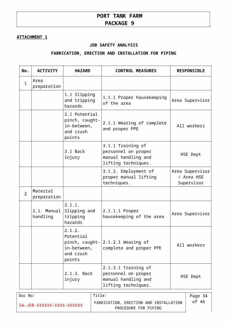
ATTACHMENT 1
JOB SAFETY ANALYSIS
FABRICATION, ERECTION AND INSTALLATION FOR PIPING
No. ACTIVITY HAZARD CONTROL MEASURES RESPONSIBLE
1Area preparation
1.1 Slipping and tripping hazards
1.1.1 Proper housekeeping of the area
Area Supervisor
2.1 Potential pinch, caught-in-between, and crush points
2.1.1 Wearing of complete and proper PPE
All workers
3.1 Back injury3.1.1 Training of personnel on proper manual handling and lifting techniques.
HSE Dept
3.1.2. Employment of proper manual lifting techniques.
Area Supervisor / Area HSE Supervisor
2Material preparation
2.1. Manual handling
2.1.1. Slipping and tripping hazards
2.1.1.1 Proper housekeeping of the area
Area Supervisor
2.1.2. Potential pinch, caught-in-between, and crush points
2.1.2.1 Wearing of complete and proper PPE
All workers
2.1.3. Back injury2.1.3.1 Training of personnel on proper manual handling and lifting techniques.
HSE Dept
2.1.3.2 Employment of proper manual lifting techniques.
Area Supervisor / Area HSE Supervisor
2.2. Using crane
2.2.1. Defective crane
2.2.1.1 Crane must have valid 3rd party inspection sticker and must have passed with Client inspection.
Area Supervisor / Area HSE Supervisor
2.2.2. Improper rigging technique
2.2.2.1 Crane must have a documented regular (i.e. monthly) maintenance inspection.
Crane Operator / Maintenance Dept
2.2.3. Defective rigging equipment
2.2.3.1 Crane must have a documented daily inspection before being used.
Crane Operator
Doc No: Title: Page 29 of 38
SA-JER-XXXXXX-XXXX-XXXXXX FABRICATION, ERECTION AND INSTALLATION PROCEDURE FOR PIPING
PORT TANK FARM PACKAGE 9
2.2.4. Incorrect identification of weight of load
2.2.4.1 An approved lifting permit must be available before any lifting activity is done.
Rigging Supervisor
2.2.5. Incorrect identification of crane lifting capacity
2.2.5.1 Weight of load must be accurately taken and should be reflected in the lifting permit. Data on the weight of the load can be taken from shipping documents or any technical specification documents.
Rigging Supervisor
2.2.6. Incompetent/non-qualified operator
2.2.6.1 A test lift should be conducted before proceeding with the actual lift to identify accurately the weight of the load and to determine the correctness of the rigging of the load (i.e. the correct center of gravity)
Crane Operator/ Rigging Supervisor
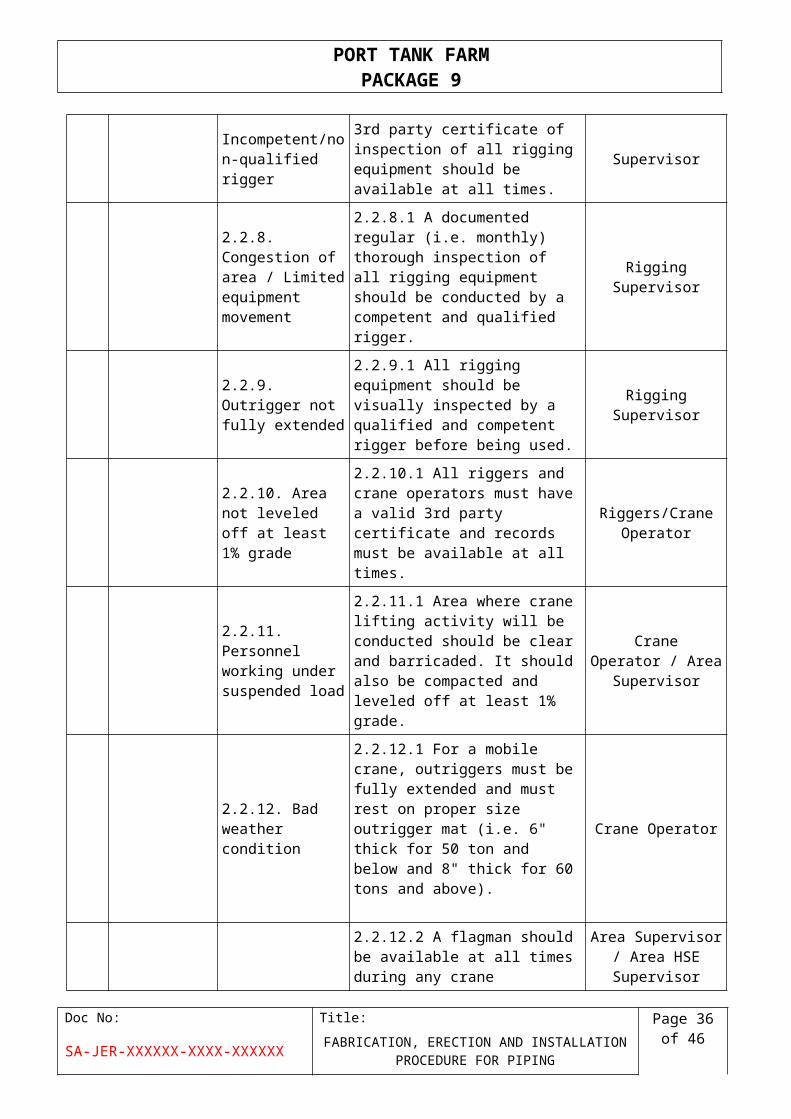
2.2.7. Incompetent/non-qualified rigger
2.2.7.1 A valid record of 3rd party certificate of inspection of all rigging equipment should be available at all times.
Rigging Supervisor
2.2.8. Congestion of area / Limited equipment movement
2.2.8.1 A documented regular (i.e. monthly) thorough inspection of all rigging equipment should be conducted by a competent and qualified rigger.
Rigging Supervisor
2.2.9. Outrigger not fully extended
2.2.9.1 All rigging equipment should be visually inspected by a qualified and competent rigger before being used.
Rigging Supervisor
2.2.10. Area not leveled off at least 1% grade
2.2.10.1 All riggers and crane operators must have a valid 3rd party certificate and records must be available at all times.
Riggers/Crane Operator
2.2.11. Personnel working under suspended load
2.2.11.1 Area where crane lifting activity will be conducted should be clear and barricaded. It should also be compacted and leveled off at least 1% grade.
Crane Operator / Area Supervisor
2.2.12. Bad weather condition
2.2.12.1 For a mobile crane, outriggers must be fully extended and must rest on proper size outrigger mat (i.e. 6" thick for 50 ton and below and 8" thick for 60 tons and above).
Crane Operator
2.2.12.2 A flagman should be available at all times during any crane movement.
Area Supervisor / Area HSE Supervisor
Doc No: Title: Page 30 of 38
SA-JER-XXXXXX-XXXX-XXXXXX FABRICATION, ERECTION AND INSTALLATION PROCEDURE FOR PIPING
PORT TANK FARM PACKAGE 9
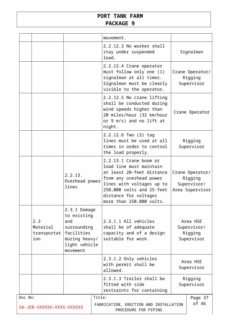
2.2.12.3 No worker shall stay under suspended load.
Signalman
2.2.12.4 Crane operator must follow only one (1) signalman at all times. Signalman must be clearly visible to the operator.
Crane Operator/ Rigging Supervisor
2.2.12.5 No crane lifting shall be conducted during wind speeds higher than 20 miles/hour (32 km/hour or 9 m/s) and no lift at night.
Crane Operator
2.2.12.6 Two (2) tag lines must be used at all times in order to control the load properly.
Rigging Supervisor
2.2.13. Overhead power lines
2.2.13.1 Crane boom or load line must maintain at least 20-feet distance from any overhead power lines with voltages up to 250,000 volts and 25-feet distance for voltages more than 250,000 volts.
Crane Operator/ Rigging Supervisor/
Area Supervisor
2.3 Material transportation
2.3.1 Damage to existing and surrounding facilities during heavy/ light vehicle movement
2.3.1.1 All vehicles shall be of adequate capacity and of a design suitable for work.
Area HSE Supervisor/ Rigging
Supervisor
2.3.1.2 Only vehicles with permit shall be allowed.
Area HSE Supervisor
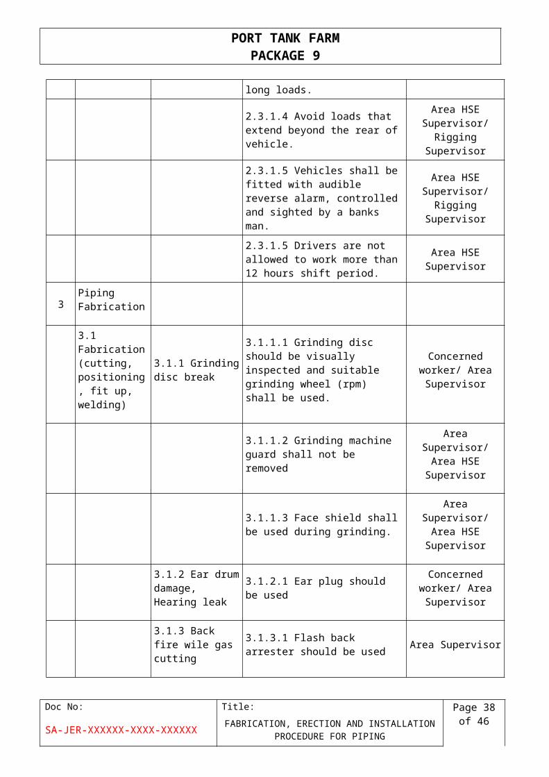
2.3.1.3 Trailer shall be fitted with side restraints for containing long loads.
Rigging Supervisor
2.3.1.4 Avoid loads that extend beyond the rear of vehicle.
Area HSE Supervisor/ Rigging
Supervisor
2.3.1.5 Vehicles shall be fitted with audible reverse alarm, controlled and sighted by a banks man.
Area HSE Supervisor/ Rigging
Supervisor
2.3.1.5 Drivers are not allowed to work more than 12 hours shift period.
Area HSE Supervisor
3Piping Fabrication
3.1 Fabrication (cutting, positioning, fit up, welding)
3.1.1 Grinding disc break
3.1.1.1 Grinding disc should be visually inspected and suitable grinding wheel (rpm) shall be used.
Concerned worker/ Area Supervisor
Doc No: Title: Page 31 of 38
SA-JER-XXXXXX-XXXX-XXXXXX FABRICATION, ERECTION AND INSTALLATION PROCEDURE FOR PIPING
PORT TANK FARM PACKAGE 9
3.1.1.2 Grinding machine guard shall not be removed
Area Supervisor/ Area HSE Supervisor
3.1.1.3 Face shield shall be used during grinding.
Area Supervisor/ Area HSE Supervisor
3.1.2 Ear drum damage, Hearing leak
3.1.2.1 Ear plug should be usedConcerned worker/
Area Supervisor
3.1.3 Back fire wile gas cutting
3.1.3.1 Flash back arrester should be used
Area Supervisor
3.1.4 Accident with Hoist hook
3.1.4.1 Visually inspect the hooks Grounding
Area Supervisor
3.1.5Object falling from stand
3.1.5.1 Object should be properly secured using slings or vise
Area Supervisor
3.1.6 Electric Shock
3.1.6.1Electric equipments and cables must be inspected and color coded
Area Supervisor /Area HSE Supervisor
3.1.6.2 ELCB (Earth leakage circuit breaker) must connected to all equipments
Area Electrical Supervisor /Area HSE Supervisor
3.1.7 Material fall in Eyes
3.1.7.1Face shield and proper safety goggles shall be used
Area Supervisor/ All workers
3.1.8 Welding spatters
3.1.8.1 Fire blanket should be used
Area Supervisor
3.2 NDT (Non Destructive Testing)
3.2.1Exposure of radiation
3.2.1.1Radiation monitoring devices, barricading, signboards
NDT Supervisor
3.2.1.2Use real-time radiation meter to monitor activity level
NDT Supervisor
3.3 Heat Treatment
3.3.1Burns3.3.1.1 Proper PPE, and safe work area preparation
PWHT Supervisor
3.3.2 Electric shock
3.3.2.1All equipments grounded, and insulated
PWHT Supervisor
Doc No: Title: Page 32 of 38
SA-JER-XXXXXX-XXXX-XXXXXX FABRICATION, ERECTION AND INSTALLATION PROCEDURE FOR PIPING
PORT TANK FARM PACKAGE 9
4 Field Erection
4.1Erection 4.1.1Crane toggle4.1.1.1 Steel plate should be used for outrigger pads
Rigging Supervisor
4.1.2 Struck by equipment
4.1.2.1Barricade the area and pictogram /signboard where necessary around the area covered with the activity.
Rigging Supervisor/ Area HSE Supervisor
4.1.2.2 Minimize people entering the area.
Rigging Supervisor
4.1.3 Scaffolding collapse
4.1.3.1 Proper base plate and every surface at ground
Scaffolding Supervisor/ Area HSE Supervisor
4.1.3.2 Wear recommended PPE and Safety harness all time.
All
4.1.3.3 Proper work platform and access means are to be secured
Scaffolding Supervisor/ Inspector
4.1.3.4 All scaffolding material should be confirmed to standard.
Scaffolding Supervisor/ Inspector
4.1.3.5 All scaffolding should have proper scaff-tag and periodic checks to be performed
Scaffolding Supervisor/ Inspector
4.1.3.6 Suitable methods for scaffolding erection shall be done
Scaffolding Supervisor/ Inspector
4.1.4 Objects /Personnel falling from temporary platform
4.1.4.1 Close supervision at all time
Scaffolding Supervisor/ Area
Supervisor
4.1.4.2 Scaffolding have Toe-board
Scaffolding Supervisor/ Area
Supervisor
4.1.4.3 Scaffolding not to be used as support for heavy loads
Scaffolding Supervisor/ Area
Supervisor
Doc No: Title: Page 33 of 38
SA-JER-XXXXXX-XXXX-XXXXXX FABRICATION, ERECTION AND INSTALLATION PROCEDURE FOR PIPING
PORT TANK FARM PACKAGE 9
4.1.4.4 Qualified and certified scaffolders to erect and dismantle scaffolding.
Scaffolding Supervisor/ Inspector
4.1.4.5 No any loose objects laying around
Scaffolding Supervisor/ Inspector
4.1.5 Chain block brake
4.1.5.1 Check safe work load of chain block, inspected and color coded
Rigging Supervisor /Area HSE Supervisor
4.1.6 Belt sling break
4.1.6.1 Check the slings for damage
Rigging Supervisor/ Area Supervisor
4.1.7 Fall or slip of men
4.1.7.1 Full body harness, proper scaffolding and lifting technique
Area Supervisor/ Rigging supervisor
5Pressure Testing
5.1 Spade breakage
5.1.1 Check spade break Area Supervisor
5.2Valve, Cap, Pipe, Failure
5.2.1 Proper inspection of the valve, pipe, etc.
Area Supervisor
5.3 Hose Failure 5.4.1 Proper inspection of hose Area Supervisor
6Flushing /Drying
6.1Hose breakage, inhalation of dust particle of exhaust.
6.1.1 Recheck all hose connection are clipped
Area Supervisor
Doc No: Title: Page 34 of 38
SA-JER-XXXXXX-XXXX-XXXXXX FABRICATION, ERECTION AND INSTALLATION PROCEDURE FOR PIPING
PORT TANK FARM PACKAGE 9
ATTACHMENT 2
WORK FLOW
PIPING PRE- FABRICATION
Doc No: Title: Page 35 of 38
SA-JER-XXXXXX-XXXX-XXXXXX FABRICATION, ERECTION AND INSTALLATION PROCEDURE FOR PIPING
PORT TANK FARM PACKAGE 9
ATTACHMENT 3
WORK FLOW
PIPING ERECTION
Doc No: Title: Page 36 of 38
SA-JER-XXXXXX-XXXX-XXXXXX FABRICATION, ERECTION AND INSTALLATION PROCEDURE FOR PIPING
PORT TANK FARM PACKAGE 9
ATTACHMENT 4
TYPICAL LIFTING INSTALLATION PLAN- PIPING
Doc No: Title: Page 37 of 38
SA-JER-XXXXXX-XXXX-XXXXXX FABRICATION, ERECTION AND INSTALLATION PROCEDURE FOR PIPING
PORT TANK FARM PACKAGE 9
ATTACHMENT 5
LIST OF INSPECTION FORMS ATTACHED
Doc No: Title: Page 38 of 38
SA-JER-XXXXXX-XXXX-XXXXXX FABRICATION, ERECTION AND INSTALLATION PROCEDURE FOR PIPING