external assessment · design, draw and dimension a fully mechanical drawing device (called a...
TRANSCRIPT

Questions: 13Pages: 13©Copyright for part(s) of this examination may be held by individuals and/or organisations otherthan the Tasmanian Secondary Assessment Board.
Tasmanian Secondary Assessment Board
DESIGN GRAPHICSSenior Secondary 5C
Subject Code: TE836
External Assessment
2003
Time: Three Hours
On the basis of your performance in this examination, the examiners will provideresults on each of the following criteria taken from the syllabus statement:
Criterion 4 Develop skills in interpreting and transferring drawings.
Criterion 5 Solve problems.

Design Graphics
Page 2
CANDIDATE INSTRUCTIONS
Candidates MUST ensure that they have addressed ALL of the externally assessed criteria on thisexamination paper.
You must answer SEVEN questions in total:
ALL FOUR questions from Section A
ONE question from each of Sections B, C and D
You should spend approximately 60 minutes on Section A and approximately 40 minutes on eachof the other three questions.
You are required to use correct linework and presentation and are encouraged to include freehandsketches, where necessary, to show the development of ideas in the solution of problems.

Design Graphics
Page 3
SECTION A
Answer ALL questions in this section.
Question 1 – This question assesses Criterion 4.
Graphically determine the true angle A between the centreline and the arrowhead on the cabinetoblique view (two-thirds depth) of the road sign shown in Figure 1.
Figure 1

Design Graphics
Page 4
Question 2 – This question assesses Criterion 5.
Figure 2 is the involute of a hexagon. Construct the generating hexagon and reproduce the involute.
Figure 2
Design Graphics
Page 5
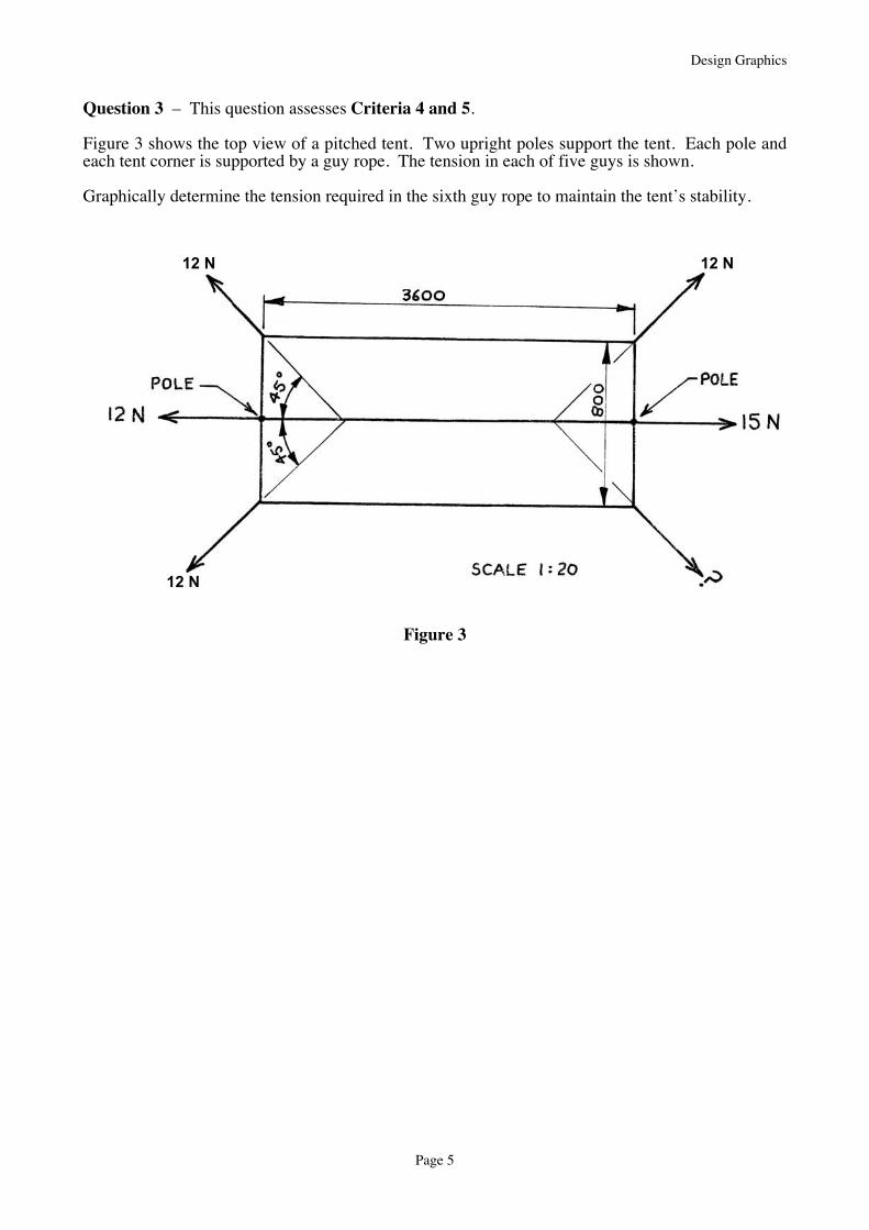
Question 3 – This question assesses Criteria 4 and 5.
Figure 3 shows the top view of a pitched tent. Two upright poles support the tent. Each pole andeach tent corner is supported by a guy rope. The tension in each of five guys is shown.
Graphically determine the tension required in the sixth guy rope to maintain the tent’s stability.
Figure 3
12 N
12 N12 N
Design Graphics
Page 6
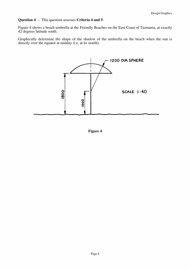
Question 4 – This question assesses Criteria 4 and 5.
Figure 4 shows a beach umbrella at the Friendly Beaches on the East Coast of Tasmania, at exactly42 degrees latitude south.
Graphically determine the shape of the shadow of the umbrella on the beach when the sun isdirectly over the equator at midday (i.e. at its zenith).
Figure 4
Design Graphics
Page 7
SECTION B
Answer one question from this section.
This section assesses Criteria 4 and 5 weighted 1:4 respectively.
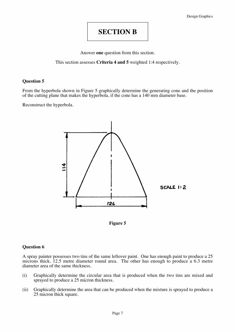
Question 5
From the hyperbola shown in Figure 5 graphically determine the generating cone and the positionof the cutting plane that makes the hyperbola, if the cone has a 140 mm diameter base.
Reconstruct the hyperbola.
Figure 5
Question 6
A spray painter possesses two tins of the same leftover paint. One has enough paint to produce a 25microns thick, 12.5 metre diameter round area. The other has enough to produce a 6.3 metrediameter area of the same thickness.
(i) Graphically determine the circular area that is produced when the two tins are mixed andsprayed to produce a 25 micron thickness.
(ii) Graphically determine the area that can be produced when the mixture is sprayed to produce a25 micron thick square.

Design Graphics
Page 8
Question 7
A spring made from 15 mm x 3 mm flat spring steel has the following dimensions:
Outside dia. 70 mmInside dia. 40 mmPitch 30 mmWinding Clockwise
Draw 60 mm of the spring.
Design Graphics
Page 9
SECTION C
Answer one question from this section.
This section assesses Criteria 4 and 5 weighted 4:1 respectively.
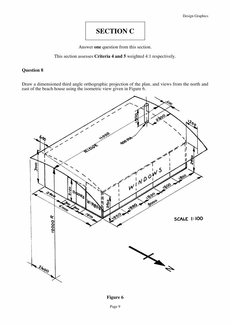
Question 8
Draw a dimensioned third angle orthographic projection of the plan, and views from the north andeast of the beach house using the isometric view given in Figure 6.
Figure 6

Design Graphics
Page 10
Question 9
Develop the bucket of the wheelbarrow shown in Figure 7.
Figure 7
Design Graphics
Page 11
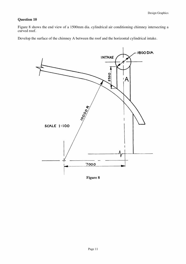
Question 10
Figure 8 shows the end view of a 1500mm dia. cylindrical air conditioning chimney intersecting acurved roof.
Develop the surface of the chimney A between the roof and the horizontal cylindrical intake.
Figure 8

Design Graphics
Page 12
SECTION D
Answer one question from this section.
This section assesses Criteria 4 and 5 weighted equally.
Question 11
In old gold mines the rock brought up from underground was usually crushed in a ‘stamp battery’,which consisted of large hammers driven by cam mechanisms, as shown in Figure 9.Design and draw a similar cam and hammer mechanism that will lift the hammer 250 mm then dropit vertically downwards in a crushing blow, then lift it, … and so on, as the cam rotates.Describe the motion as a performance graph.Once drawn, name the form of motion that the cam imparts to the hammer.
Figure 9
Question 12
Design, draw and dimension a fully mechanical drawing device (called a pantograph) that willallow the operator to trace around a diagram or figure using a sensor pen and reproduce the samediagram or figure in ink at twice the size on an adjacent sheet.
Use additional freehand sketches to show how the pantograph will operate.
Design Graphics
Page 13
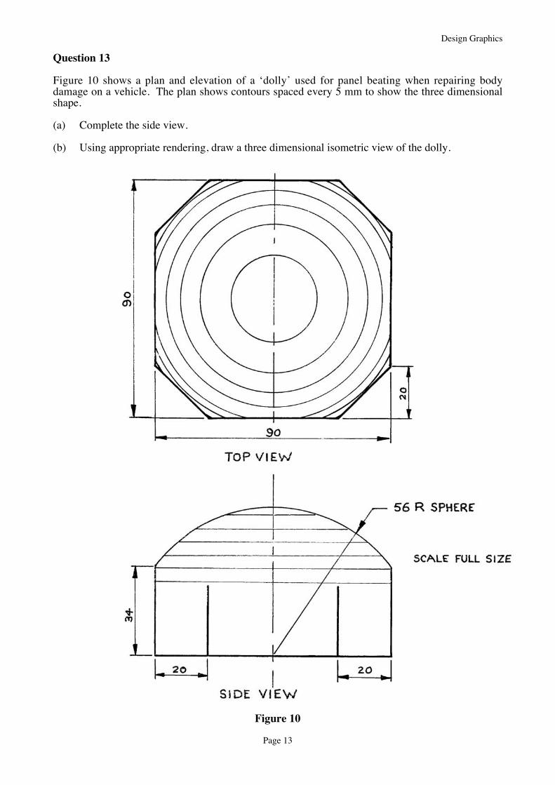
Question 13
Figure 10 shows a plan and elevation of a ‘dolly’ used for panel beating when repairing bodydamage on a vehicle. The plan shows contours spaced every 5 mm to show the three dimensionalshape.
(a) Complete the side view.
(b) Using appropriate rendering, draw a three dimensional isometric view of the dolly.
Figure 10