kinematics of pantograph
TRANSCRIPT

KSME Joumal, Vol. 2, No. 1, pp. 69~78, 1988. 69
THE MECHANICAL EFFICIENCY AND KINEMATICS OF P A N T O G R A P H - T Y P E MANIPULATORS
Shin-Min Song* and Jong-Kil Lee*
(Received May, 7, 1988)
Pantograph mechanism has been well known for its motion feature of decoupled kinematics. Planar pantograph mechanism has been extensively used in machinery since the seventeenth century. Recently, three dimensional pantographs have been used in walking machine leg and manipulator designs. This is because, the pantograph mechanism possesses the following advantages decoupled kinematics, higher energy efficiency, good rigidity, less link inertia and compact drive systems. In this paper, the mechanical efficiency of the kinematics of pantograph type manipulators are studied. The mechanical efficiency of pantograph mechanisms and conventional open-chain and closed-chain type manipulators are studied and evaluated using the concept of modified geometric work. The kinematics of six-d.o.f., pantograph type manipulators are studied and special :mechanisms which simplify the kinematics are introduced. The computational complexity of both Cartesian and cylindrical type pantograph manipulators are evaluated and compared with a PUMA type manipulator.
Key Words : Pantograph Mechanism, Mechanical Efficiency, Inverse Position Analysis
1. INTRODUCTION
In a strict sense, the term pantograph mechanism is reserved for a special type of five-link mechanism (see Fig. 1) which possesses a decoupled kinematic relationship between the output motion of the reference point F and the two input degrees of motion. The closed-chain structure is a parallelo- gram and points A, B and F are maintained collinear at all times. The driving points of the two input degrees of freedom can be respectively assigned to points A and B, or they can be both assigned to either one of these two points. If the two input degrees of motion are driven separately by two linear actuators which are parallel with the two axes of the refer- ence coordinate system, the kinematic relationship between input and output motion becomes decoupled. This type of pantograph mechanism, which was called simple pantogrpah in (Song, Lee and Waldrom, 1987) has been extensively used in embroidering machines, copying machines and magnifying mechanisms since the seventeenth century. Later, in the nineteenth century, a more general form of pantograph, the skew pantograph or the plagiograph, as it was called by its inventor, was introduced by Sylvester (Hobson, et al., 1953). Referring to Figure 2, the skew pantograph is obtained by attaching two similar triangulated rigid links to the parallelo- gram ACDE. If one carefully arranges the orientation of the two input linear axes with respect to the reference coordinate system, a decoupled kinematic relationship which is similar to that of the simple pantographs can be obtained. The way to define the orientation of the input linear axes was shown in (Song, Lee and Waldron, 1987) and will be reviewed in a
*Department of Mechanical Engineering, University of lllinois at Chicago, Chicago, Illinois 60680, U.S.A.
later section.
Although both the simple and skew pantographs are planar mechanisms, they can be extended to a three-dimensional mechanism by the following two methods : The first method is to mount the frame on the base via a revolute joint (see Fig.
A k;
D
t? 0 ~
Fig. 1 Simple pantographs
B
Fig. 2 A skew pantograph

70 S h i n - M i n Song and J o n g - K i l Lee
n~r I1alnt.~ Z (J D
I I I
U I �9 "a~t uat' ,,r a• f r a m e a x i s I
I
y I
/ / I
~ X
Fig. 3 A cylindrical type pantograph manipulator
3). If the axis of the revolute joint is in the plane which contains the planar pantograph, the mechanism has decou- pled kinematics in a cylindrical coordinate system. This type of pantograph is called a cylindrical pantograph. The second method is to mount the two, input points A and B on a pair of revolute joints which have their axes parallel to one another (see Fig. 4). Thus, a lateral movement of one input point will cause the pantograph to stretch and rotate simultaneously, and the motion of the output point becomes three dimen- sional. Although a skew pantograph can generate three- dimensional motion, it was shown in (Song, Lee and Waldron, 1987) that only the simple pantographs have decoupled kinematics in Cartesian coordinate system. This type of three-dimensional pantograph is called Cartesian type panto- graph and was first introduced by Hirose and Umetani in (Hirose and Umetani, 1980). They designed a quadrupedal walking machine with four Cartesian type pantograph legs.
In recent years, pantograph mechanisms have been fre- quently used in the robotics area, such as in the design of walking machine legs (Hirose and Umetani, 1980; Hirose, 1984; Kesseis, Rambaut and Penne, 1981; Song, Waldron and Kinzel, 1985) and manipulators (GAC Corp., 1982 ; Song
(
F
and Lin, 1987; Yang and Lin, 1985). This is because, in addition to decoupled kinematics, this ancient mechanism possesses many other important advantages. These advan- tages include a high mechanical efficiency, high payload/ weight ratio, low link inertia and compact drive systems. The high mechanical energy efficiency is because no geometric work is consumed during operation. This will be explained in detail in a later section. The high payload/weight ratio is due to the closed-chain structure of a pantograph. The low link inertia is because the actuators are mounted low on the rotating base. The compact size of the drive systems are due to the magnification motion feature of pantographs. Because of these advantages, pantograph mechanisms are especially suitable for the applications of walking machines, where computational efficiency of inverse kinematics and dynamics (Song, lee and Waldron, 1987), energy efficiency and mechani- cal strength are important. Since the demands on computational and mechanical efficiencies of manipulators are becoming more strict, pantograph mechanisms will be more attractive in future manipulator design.
Although some of the advantages of pantograph mecha- nisms have been scatteredly mentioned in literature (Hirose and Umetani, 1980; Hirose, 1984;Hobson, et. al., 1953; Song, Waldron and Kinzel, 1985 ; Song and Lin, 1987 ; Yang and Lin, 1985), the advantages of high mechanical efficiency and decoupled kinematics were not fully investigated. Hence, it is the goal of this paper to present to the readers a complete study of these two aspects. In the following, the basic kinematics of Cartesian and cylindrical pantographs is revi- ewed first. The mechanical efficiency of the pantograph is then studied and compared with other types of manipulators. The kinematics of a six-d.o.f, pantograph type manipulators are is then studied in detail. Two wrist mechanisms which can simplify the kinematic relationships are also discussed.
2. BASIC KINEMATIC F E A T U R E S OF P A N T O G R A P H S
The basic kinematic features of pantographs are reviewed in this section. Figure 2 shows a skew pantograph mecha- nism. The angle 0 is called the skew angle. ACDE is a parallelogram and BCD and DEF are two similar triangulat- ed links. It has been proven that 2 A B F is similar to either 2 BCD or AIDEF as long as ACDE is kept a parallelogram (Hobson, et. al., 1953). Thus, the motion of a pantograph can be fully represented by the imaginary, dashed triangle ABF, which was called equivalent triangle in (Song, Waldron and Kinzel, 1985). That is, given the positions of points A and B, the position of point F can be obtained by constructing the equivalent triangle.
The fundamental motion feature of a skew pantograph is stated as: If point A is fixed and point B traces a given curve, then point F traces a similar curve. The magnitude of the curve is magnified by a ratio R and the orientation is rotated through the skew angle 0 with respect to the given curve. Similarly, if point B is fixed and point A traces a given curve, then point F traces a given curve, The magnitude of the curve is magnified by a ratio R" and the orientation is rotated through an angle r with respect to the given curve, where
Fig. 4 Schematic diagram of a three-d.o.f. Cartesian type panto- A F , B F 2 1 graph R = A B ' R = A B - = ( I + R -2R .cos0 )5 (1)
THE MECHANICAL EFFICIENCY AND KINEMATICS OF PANTOGRAPH-TYPE MANIPULATORS 71
/ V
Fig. 5
[' V
'2 "I �9 [~ 0
'~' <,~ '] \
\ \ \ \ \ \ \
\. \ \ \ \ x \ ~
: ~ x " k v J" \ ~ 'Nb,
( :~{, I Ca>e"
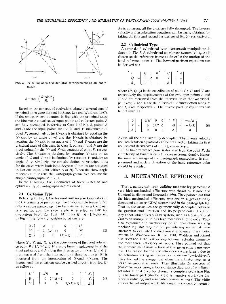
Principal axes and actuator arrangements of 2D panto- graph
= tan ~{ R.sinfl__] (2) r \ R~ ]
Based on the concept: of equivalent triangle, several sets of principal axes were defined in (Song, Lee and Waldron, 1987). If the actuators are mounted in line with the principal axes, the kinematic equations of input points and reference point F are fully decoupled. Referring to Case 1 of Fig. 5, points A and B are the input points for the X-and Y-movements of
point F, respectively. The U-axis is obtained by rotating the X-ax is by an angle of - r and the V-axis is obtained by rotating the Y-axis by an angle of 0 V-and V-axes are the principal axes of this case. In Case 2, points A and B are the input points for the Y-and X-movements of point F, respec- tively. The U-axis is obtained by rotating X-ax is by an angle of -0 and V-axis is obtained by rotating Y-axis by an angle of -r Similarly, one can also define the principal axes for the cases where both input degrees of motion are assigned to just one input point (either A or B). When the skew angle 0 becomes 0 ~ or 180 ~ the pantograph geometries become the simple pantographs in Fig. 1.
In the following, the kinematics of both Cartesian and cylindrical type pantographs are reviewed :
2.1 Cartesian Type Referring to Fig. 4, the forward and inverse kinematics of
the Cartesian type pantograph have very simple forms. Since only a simple pantograph can be constructed as a Cartesian type pantograph, the skew angle is selected as 180 ~ for discussions. From Eq. I1), 0 = 180 ~ gives R' = R + 1. Referring to Fig. 4, the forward position equations are :
[x.] 1.0 0jill Y~ = 0 ( R + I ) 0 (3)
Zj 0 0 ( R + I )
where Xf, I/i and ZI are the coordinates of the hand referen- ce point F ; U, W and V are the linear displacements of the input points A and B along the three actuator axes�9 U and V are measured from the intersection of these two axes. W is measured from the intersection of U-and W-axes. The inverse position equations can be derived directly from Eq. (3) as follows :
= 0 I/(R+ I) Y, (4)
0 0 t / ( R + I ) Z,
As is apparent, all the d.o.f, are fully decoupled. The inverse velocity and acceleration equations can be easily obtained by taking the first and second derivatives of Eq. (4), respectively.
2.2 Cylindrical Type A three-d.o.f, cylindrical type pantograph manipulator is
shown in Fig. 3. A cylindrical coordinate system (P, Q, r is chosen as the reference frame to describe the motion of the hand reference point F. The forward position equations can be derived as:
I:l [ "~ ~ [!1 [!1 -- 0 R 0 +
o o 1 (5)
where (P, Q, r is the coordinates of point F ; U and V are respectively the displacements of the two input points A and B and are measured from the intersection of the two princi- pal axes ; e and h are the offsets of the intersection along P and Q axes, respectively. The inverse position equations can be obtained as:
~ ~ ,,. 0 0 [il [ j + < (6)
Again, all the d.o.f, are fully decoupled. The inverse velocity and acceleration equations can be obtained by taking the first and second derivatives of Eq. (6), respectively.
If the hand reference point is deviated from the point F, the complexity of kinematics will increase tremendously. Hence, the main advantage of the pantograph manipulator is com- promised and such a deviation of the hand reference point should be avoided.
3. M E C H A N I C A L E F F I C I E N C Y
That a pantograph type walking machine leg possesses a very high mechanical efficiency was shown by Hirose and Umetani in Hirose and Umetani, (1980). They pointed out that the high mechanical efficiency was due to a gravitationlly decoupled actuator (GDA) system used in the pantograph leg. That is, the actuators are geometrically decoupled between tim gravitational direction and its perpendicular direction�9 Any robot which uses a GDA system, such as a conventional Cartesian manipulator, has high mechanical efficiency�9 They also explained the inefficiency of an open-chain walking machine leg. But they did not provide any numerical mea- surement to evaluate the mechanical efficiency of a robotic system. In (Waldrom and Kinzel, 1981) Waldron and Kinzel discussed about the relationship between actuator geometry and mechanical efficiency in robots. They pointed out that the efficiencies of most robots of this generation were very low. The reason for the low efficiencies were largely due to the actuators' acting as brakes ; i.e., they are "back-driven". They termed the energy lost when the actuator acts as a brake as geometric work. They illustrate the concept of geometric work using a force-distance diagram of one linear actuator after it executes through a complete cycle (see Fig. 6). The lower part (shaded area) is negative work (the dis- tance is reducing) and was called geometric work. The white area is the net output work. Although the concept of geomet-
72 Shin-Min Song and Jong Kil Lee
Fig. 6
~'= w , , W
I ) i s p ] a c e m e n t ( l 1!
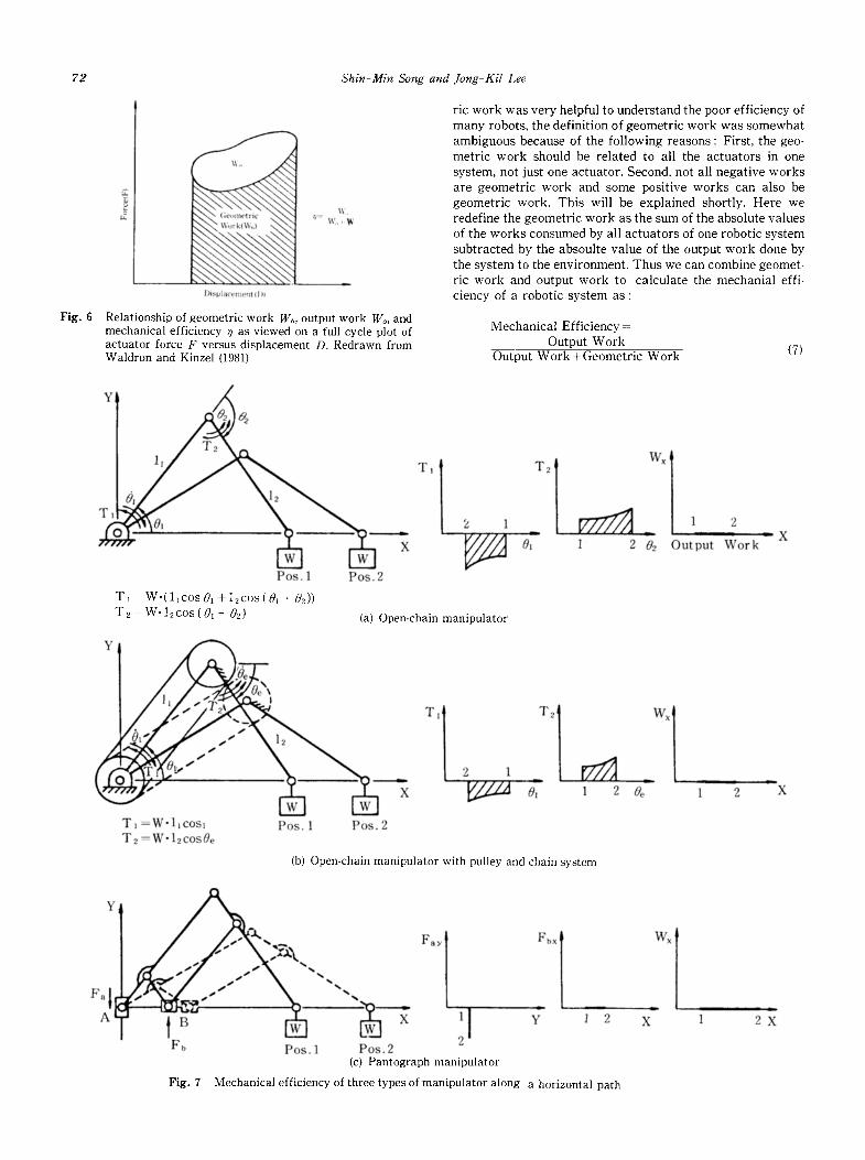
Relationship of geometric work Wb, output work Wo, and mechanical efficiency ~ as viewed on a full cycle plot of actuator force F versus displacement D. Redrawn from Waldron and Kinzel (1981)
Y
T
6 l l J
T2=W-12cos(01+02)
ric work was very helpful to understand the poor efficiency of many robots, the definition of geometric work was somewhat ambiguous because of the following reasons : First, the geo- metric work should be related to all the actuators in one system, not just one actuator. Second, not all negative works are geometric work and some positive works can also be geometric work. This will be explained shortly. Here we redefine the geometric work as the sum of the absolute values of the works consumed by all actuators of one robotic system subtracted by the absoulte value of the output work done by the system to the environment. Thus we can combine geomet- ric work and output work to calculate the mechanial effi- ciency of a robotic system as :
Mechanical Efficiency= Output Work
Output Work +Geometric Work (7)
11 T l
2 1 m
Pos. 1 Pos. 2
T, = W - ( l l c o s 01 +12cos(0l + O~))
(a) Open-chain manipulator
Y
T2
o7
w~
1 2 92 Output Work " X
T1 W-l~COSl Pos. 1 Pos.2 T2 =Wo 12cos0e
(b) Open-chain manipulator with pulley and chain system
~ a , . , ~, Fay hx
Fb Pos. 1 Pos. 2 ~ d ]
Y 1
(c) Pantograph manipulator
Fig. 7
1 2
Mechanical efficiency of three types of manipulator along a horizontal path
w~
1_
X 1
|
1 2 X
2 X

72 Shin-Min Song and Jong Kil Lee
Fig. 6
~'= w , , W
I ) i s p ] a c e m e n t ( l 1!
Relationship of geometric work Wb, output work Wo, and mechanical efficiency ~ as viewed on a full cycle plot of actuator force F versus displacement D. Redrawn from Waldron and Kinzel (1981)
Y
T
6 l l J
T2=W-12cos(01+02)
ric work was very helpful to understand the poor efficiency of many robots, the definition of geometric work was somewhat ambiguous because of the following reasons : First, the geo- metric work should be related to all the actuators in one system, not just one actuator. Second, not all negative works are geometric work and some positive works can also be geometric work. This will be explained shortly. Here we redefine the geometric work as the sum of the absolute values of the works consumed by all actuators of one robotic system subtracted by the absoulte value of the output work done by the system to the environment. Thus we can combine geomet- ric work and output work to calculate the mechanial effi- ciency of a robotic system as :
Mechanical Efficiency= Output Work
Output Work +Geometric Work (7)
11 T l
2 1 m
Pos. 1 Pos. 2
T, = W - ( l l c o s 01 +12cos(0l + O~))
(a) Open-chain manipulator
Y
T2
o7
w~
1 2 92 Output Work " X
T1 W-l~COSl Pos. 1 Pos.2 T2 =Wo 12cos0e
(b) Open-chain manipulator with pulley and chain system
~ a , . , ~, Fay hx
Fb Pos. 1 Pos. 2 ~ d ]
Y 1
(c) Pantograph manipulator
Fig. 7
1 2
Mechanical efficiency of three types of manipulator along a horizontal path
w~
1_
X 1
|
1 2 X
2 X

74 Shin-Min Song and .long Ki l Lee
path with a constant speed. We assume that the system is frictionless ; the two links are weightless and only the object carried by the end-effector has significant weight. Since there is no change in the energy state of the object, the output work done by the maniPulator to the object is zero. The motor at the base joint is acting as a brake and doing negative work because the output torque is in the opposite direction of the motor motion. The motor at the elbow joint is doing positive work. The overall works done by these two motors are shown in Fig. 7 (a). The area under T1 should be equal to the area under 7"2 since the sum of them is equal to the output work which is zero. This also means that all the positive work done by the elbow motor is entirely consumed by the base motor as negative work. Both the positive and negative works contrib- ute no output work and are related to the geometry of the manipulator. Hence, the sum of the absolute values of these two works js the geometric work of the system. Now, refer- ring to Fig. 7 (b), if we mount a pulley and chain system on the two joints and move the elbow motor to the base to be co-axial with the base motor, the geometric work of the system is reduced. This is because the torque at joint 2 is transmitted to the elbow motor through the chain system and the torque at the base motor becomes W-11cos01. The angu- lar displacement of the elbow motor is also changed. Hence, we can improve the mechanical efficiency of the two-link system by adding such a chain and pulley system. The improvement will be even greater if we consider the weight of the elbow motor in the calculation. Now, if we replace the chain and pulley system with a parallelogram as it is shown in Fig. 8, the geometric work remains unchanged. The func- tion of the parallelogram is kinematically equivalent to the pully and chain system. Now, let us consider the case of a pantograph manipulator. Referring to Fig. 7 (c), the vertical actuator is fixed and doing no work. The horizontal actuator is moving frictionlessly and also doing no work. Thus, geo- metric work is zero.
Let us consider the case that the end-effector is moving downward along a vertical path. For the open-chain manipu- lator, referring to Fig. 9 (a), the base motor is doing negative work and the elbow motor is doing positive work. The output work is negative since the potential energy of the object is reduced. Since the sum of the negative and positive works of the two motors should be equal to the negative output work, the geometric work is equal to twice the positive work of the elbow motor. For the open-chain manipulator with pulley and chain system, the geometric work is reduced due to the above-mentioned reason [see Fig. 9 (b)]. The same situation is found in the closed-chain parallelogram manipulator. As for a pantograph manipulator, referring to Fig. 9 (c), the horizontal actuator is fixed and doing no work and the veritical actuator is doing negative work. Since the amount of the negative work is equal to the negative output work, the geometric work is zero. Hence, we may conclude that a closed-chain manipulator (or an open-chain manipulator with pulley and chain system) has better mechanical efficiency than an open-chain manipulator and a pantograph type manipulator has the best mechanical efficiency of all type 1 actuators.
4. KINEMATICS OF SIX-D.O.F. P A N T O G R A P H M A N I P U L A - TORS
We have seen the kinematics of three-dimensional panto-
graphs in a previous section. In this section, we will discuss about the kinematics of six-d.o.f, pantograph type manipula- tors. A six-d.o.f, pantograph type manipulator can be obtained by attaching a three-roll wrist at the end link of a three-dimensional pantograph. The wrist center should be coincident with the point F in order to have a simpler kinematic relationship. For a six-d.o.f., Cartesian type panto- graph manipulator (referring to Fig. 4), the inverse position, velocity and acceleration analyses of the first three axes (U, V and W) are very simple since these three degrees of
freedom are fully decoupled. The analyses 9f the last three axes (04, 3s and 06), however, are not that simple due to the following reasons : The wrist experiences a pitching motion when either one or both of the first two axes (U and V) move. That is, the angle a2 changes. Also, the wrist experi- ences both a pitching and yawing when the third axis W moves. This is, both ~z2 and r change. Since these pitching and yawing motions as well as the last three joint axes affect the orientation of the wrist, the inverse position analysis of the last three axes is more complicated. The inverse velocity and acceleration analyses become very complicated because the first and second derivatives of the angle a2 have very compli- cated forms [refer to Eq. (51) in Appendix). Thus, the advan- tage of simple kinematics diminishes. Hirose and Umetani introduced a pair of differential mechanisms which can elimi- nate the unwanted pitching and yawing motions of the wrist due to the motions of the first three axes (Hirose and Umetani, 1980). After some modification this pair of differen- tial mechanisms is drawn in Fig. 10. During motion, the bottom bevel gear at joint U does not rotate and, if both motors 4 and 5 are stationary, the yawing motion of the wrist is eliminated by the motion of the differential mechanism. Moreover, the pitching motion is eliminated by the parallelo- gram motion performed through the pulley and chain system. Hence, the kinematics of the last three d.o.f, is fully decou- pled from the first three d.o.f.. The derivation of the kinematic of equations is straightforward and is not present- ed here. The other advantage of this mechanism is that Motors 4 and 5, which control the pitching and yawing motion of the wrist through the differential mechanism, are mounted low so that the wrist inertia is reduced.
/,' / " , ' , , I X , "\ / / / i , / ',. \ ,, ,,
I / / i \ r \ - ~ \ \ I I ~ /.~r'~..~ " / ~ \ ~ \ \ \ \ i h " ~ 1 - ~ / I ' , \ \ \ \
�9 ' \ \ \ \ / ; ,, .,.',,,,f / "., ,, \ . , ,.
% M,,~.r6
Fig. 10 A six-d.o.f. Cartesian type pantograph manipulator with a pair of differential mechanisms
THE MECHANICAL EFFICIENCY AND KINEMATICS OF P A N T O G R A P H - T Y P E MANIPULATORS 75
Z,,, Z,, Z:
[ h
Y, X~ Y' Y
X. X, U,
X,X,.
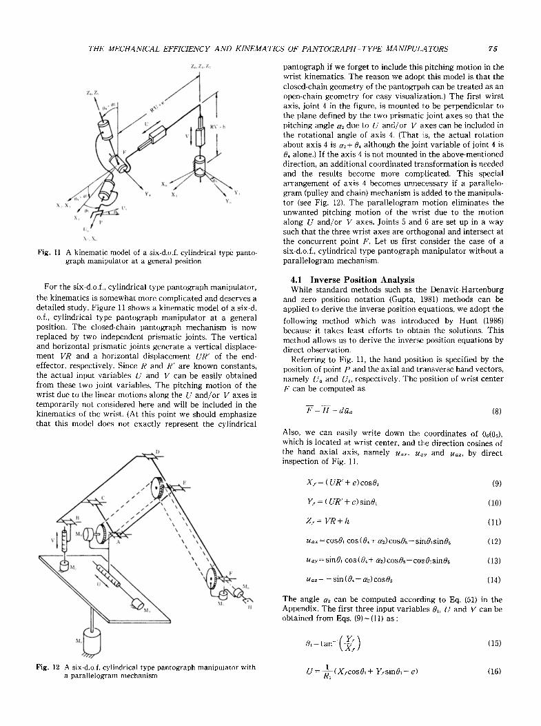
Fig. 11 A kinematic model of a six-d.o.f, cylindrical type panto- graph manipulator at a general position
pantograph if we forget to include this pitching motion in the wrist kinematics. The reason we adopt this model is that the closed-chain geometry of the pantogrpah can be treated as an open-chain geometry for easy visualization.) The first wirst axis, joint 4 in the figure, is mounted to be perpendicular to the plane defined by the two prismatic joint axes so that the pitching angle a2 due to U and/or V axes can be included in the rotational angle of axis 4. (That is, the actual rotation about axis 4 is az+ 04 although the joint variable of joint 4 is 0, alone.) If the axis 4 is not mounted in the above-mentioned direction, an additional coordinated transformation is needed and the results become more complicated. This special arrangement of axis 4 becomes unnecessary if a parallelo- gram (pulley and chain) mechanism is added to the manipula- tor (see Fig. t2). The parallelogram motion eliminates the unwanted pitching motion of the wrist due to the motion along U and/or V axes. Joints 5 and 6 are set up in a way such that the three wrist axes are orthogonal and intersect at the concurrent point F. Let us first consider the case of a six-d.o.f., cylindrical type pantograph manipulator without a parallelogram mechanism.
For the six-d.o.f., cylindrical type pantograph manipulator,
the kinematics is somewhat more complicated and deserves a detailed study. Figure 11 shows a kinematic model of a six-& o.f., cylindrical type pantograph manipulator at a general position. The closed-chain pantograph mechanism is now replaced by two independent prismatic joints. The vertical and horizontal prismatic joints generate a vertical displace- ment VR and a horizontal displacement UR" of the end- effector, respectively. Since R and R' are known constants, the actual input variables U and V can be easily obtained from these two joint variables. The pitching motion of the wrist due to the linear motions along the U and/or V axes is temporarily not considered here and will be included in the kinematics of the wrist. (At this point we should emphasize that this model does not exactly represent the cylindrical
4.1 Inverse Posit ion Analysis While standard methods such as the Denavit-Hartenburg
and zero position notation (Gupta, 1981) methods can be applied to derive the inverse position equations, we adopt the
following method which was introduced by Hunt (1986) because it takes least efforts to obtain the solutions. This method allows us to derive the inverse position equations by direct observation.
Referring to Fig. 11, the hand position is specified by the position of point P and the axial and transverse hand vectors, namely Ua and Ut, respectively. The position of wrist center F can be computed as
F = H - d~a (8)
Also, we can easily write down the coordinates of 0d0s), which is located at wrist center, and the direction cosines of the hand axial axis, namely uax, ua.y and ua~, by direct inspection of Fig. 11.
V I
/ /
(' / /
c~ 1 /
\ / . / \ \ \
k \ \ \ \
\
% \ \ \ F
M, II
X f = ( UR' + e)cosO~
Y j = ( UR" + e) sinO1
Z j = V R + h
u ~ =cosO~ cos (04 + a2) cosOs- sinO~sin05
u~y = sin0~ cos (0, + a2) cosOs + cos0~sin0s
ua, = - sin (0, + a2) cos0s
(9)
(10)
(11)
(12)
(13)
(14)
The angle a2 can be computed according to Eq. (51) in the Appendix. The first three input variables 0,, U and V can be obtained from Eqs. (9)-(11) as:
M~ 0~ = tan-~(~(~ - ) (15) f
Fig. 12 A six-d.o.f, cylindrical type pantograph manipulator with ~_ a parallelogram mechanism U = (X/c0s0~+ Y/sin0~-e) (16)

76 Shin-Min Song and Jong-Kil Lee
V = I ( z ~ - h ) (17) = tan_~( sin& ~ (28) 0~ \ cos0~ /
El iminat ing the terms which contain 0 , + a~ in Eqs. (12), (13) leads to the following solution of joint angle 0 s :
0 s= s in- ' (u=~cos0~- u ~ s i n 0 , ) (18) Hence, we have two solutions of 0s. Now, el iminating the terms which contain 0s in Eqs. (12)~(14) gives the solutions of c o s ( ~ + a~) and sin(04+a~) as :
u~cos0~ + u~us in0 , cos (04 + a~) = cos0s (19)
s in(04+ a~) - u~, cos0s (20)
This gives
0, = - a~ + tan%( sin (0~+ ff~)
(21) cos (04 + a~) / \
4 . 2 I n v e r s e V e l o c i t y A n a l y s i s In a six degrees-of-freedom manipulator, the six joint rates
( 4 1 - 46) of a manipulator are related to the anglar veloci ty (con) and linear velocity (~7~) of the hand by a 6 • Jacobian mat r ix [J] (Whitney, 1972). The Jacobian mat r ix can be formed according to the following equat ion :
i ~ col. jt~ col. (prismatic) (revolute)
where u, is the unit vector along joint i ; Pj is a point at joint j and H is a point at the hand. Vector PjH is a vector from P~ to point H. The i t~ column is applied to a revolute joint. In order to obtain a simple form of the Jacobian matr ix, we will formulate the Jacobian mat r ix according to an imagi- nary point F which is at tached at the hand and is coincident with the wrist center. The linear veloci ty of point F can be calculated from the known linear veloci ty at the tip of the hand as :
The t ransverse vector ut is used to calculated 06. Vector ut can be related to the unit vector j by the fol lowing corrdinat- ed t ransformat ions :
~, = R,R2R3R4RsR8 ] (22)
where f = (0,1,0) t and R / s are the rota t ion matr ices which can be constructed according to the coordinate systems. It should be noticed that the coordinate systems are not set up accord- ing to the Denavi t -Har tenburg notation.
[R,] = sin01 cos0~ , [R2]=[Ra] = 0 1 , 0 0 0 0
cosc~ 0 sing o ]
[k4]: o 1 c 'osJ - sinc~ 0
[Rs] = sin0s cos0s , [R~]= 0 cos06 - s in06 0 0 0 sin06 cos06
where 8=04+a2. Multiplying both sides of Eq. (22) by (R~R2R3) '~ and expanding both sides gives three equat ions :
ut~cos0~ + utysin0~ = -cos3sinOscosO6+sinSsin06 (23)
ut~sin0, + ut~cos0~ = cos0scos0~ (24)
ut , = sinc~ sin05cos06 + cos8 sin08 (25)
El iminat ing the terms which contain 0s from Eqs. (23) and (25) gives the solution for sin0~, and cos0~ from Eq. (24) as :
cos06 - u,xsin0~ + m~cos0, cos05 (26)
sin06 = ( ut,cos0~ + utysinO,) sin3 + ut~cos3 (27)
~ / = g h - Nh • d (30)
Where d is the distance from wrist center to the hand point H. The angular velocity is the same for all points on the same rigid body. Hence,
c5/ chh (31)
Since the end-effector reference point is now selected at the wrist center where three axes are co-intersecting, the Jacobian mat r ix according to Eq, (29) becomes :
[J] [ a, o o a4 z~s a0] zL• r~ uz u3 0 0 0
(32)
where r, is the position vector of wrist point F in the fixed coordinate. Then by observat ion of Fig. 11 we can easily obtain the elements of Jacobian matr ix as :
0 0 0 - sin0, cos0,sin3
0 0 0
g/ - (R 'U+e)s inO~ 0 R'cos0~
(R'U+e)cosO~ 0 R'sin0~
0 R cos0~cosc~cos 0 s - sin0,sin05]
sin 0,cosc~ cos 0s + cos 0, sin0~]
/ 0 J
cos0~ sin0~cos3
0 cosa
0 0
0 0
0 0
04 (33)
It should be noticed that columns 2 and 3, respectively, are multiplied by constants R and R'. This is because the joint variables of these two joints were selected R V and R'U, respectively, and only l)" and 0 should remain in the 6 x 1 column vector. Now, we have to include the joint rate change
THE MECHANICAL EFFICIENCY AND KINEMATICS OF PANTO G R A P H - T Y P E MANIPULATORS 77
a~ into the top three elements of columns 2 and 3 (Remember that the model in Fig. 11 does not exactly represent the
motion of a pantograph.) In order to do this we have to differentiate a2 [refer to Eq. (51) in Appendix]. The resultant equation is quite complicated and the terms of U and II are coupled together. We can set one of Ll and l? to zero to obtain the relationship of d,2 and the other. Thus, we can obtain the following equation :
a 2 = A . I J + B . 9 (34)
joint rates are solved from Eq. (36) through (38) as:
0s = (W/xcosOl+wsysinO1)sin~4+ (wfz-- 01)C0S04 (45)
�9 1 06 = f { (O)fxCOS 01 + O.)fy S in 01 ) COS 04
- (cos.- 01)sin0,} (46)
t)~ = - w/~sin01 + w/ycos 01 - O~sin 05 (47)
where A and B are very lengthy coefficients. Finally, the Jacobian matrix of the six-d.o.f., cylindrical type manipulator is obtained by replacing the upper left 3 • 3 matrix of Eq. (33) with the following: matrix :
0 -B-s in0~ ] - A" sin01] l
0 B'cos01 A- 1 0 :os01
(35)
Since the computation of coefficients A and B are computa- tionally inefficient, the simple kinematics of the three- dimensional cylindrical pantograph is no more maintained. Thus, from the point of view of computational efficiency, it is more advantageous to include a parallelogram mechanism into the system Isee Fig. 12). The parallelogram motion through the pulley and chain system eliminates the unwanted pitching motion of the wrist. With such an inclusion, the Jacobian matrix of the six-d.o.f., cylindrical type pantagraph manipulator is exactly the same as in Eq. (33), except that the angle 3 should be replaced with 0~ since the angle a2 is no more in existence. The inverse velocity analysis is obtained by multiplying Eq. (33) out :
W/x = -- O, sin 01 + 05C0 S 01sin 4 + 08 (COS 01 CO S4COS Os - sinOlsinOs) (36)
co/y = + O,sin01 + OssinO~sim + O~ (sinOlcos.cos05 - cosO~s:inOs) (37)
w/z = 0l + 05cos4- t~6sin0,cos0s (38)
vsx = - t~l (R' U + e) sin01 +/_) R'cos01 (39)
v/~ = t~l (R' U + e)cos01 + U R'sin01 (40)
4.3 C O M P U T A T I O N A L C O M P L E X I T Y In order to get a feeling of the computational complexity of
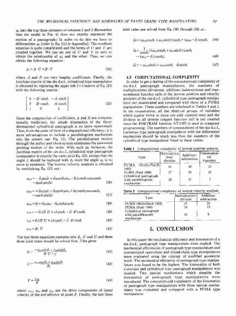
six-d.o.f, pantograph manipulators, the numbers of multiplications (divisions), additions (subtractions) and tran- scendental function calls of the inw~rse position and velocity analyses of the six-d.o.f., cylindrical type pantograph manipu- lator are mumerated and compared with those of a PUMA manipulator. These numbers are tabulated in Tables 1 and 2. In the enumeration, all the identical groups of variables which appear twice or more are only counted once and the division in all inverse tangent function call is not counted since the FOR'FRAM function ATAM2 is used in computer programming. The numbers of computations of the six-d.o.f., Cartesian type pantograph manipulator with the differential mechanism should be much less than the numbers of the cylindrical type manipulator listed in these tables.
T a b l e 1 Computational complexity of inverse position analysis
Mult ipl ica- Addition/ ['ranscenden- tal Type tion/ subtraction
division Function PUMA (Hollerbach 1983) PUMA (Paul 1986) Cylindrical pantograph with parallelogram mechanism
64
37
20
38
26
10
10
7 11
T a b l e 2 Computational complexity of inverse velocity analysis Multiplicaton/ Addition/
Type division subtraction PUMA (Hollerbach 1983) 37 25 PUMA (Pual 1986) 24 19 Cylindrical pantograph with parallelogram 18 9 mechanism
v/x = R. l)" (41)
The last three equations contains only t~l, I2 and O and these three joint rates should be solved first. This gives
O~ = - vsxsinO~ + vs~cosO~ (42) R ' U + e
0 : v/xcos01 + V/ysin01 (43) RI
I2= vs~ (44) R
where V/x, v/y and vs, are the three components of linear velocity of the end effector at point F. Finally, the last three
5. CONCLUSION
In this paper the mechanical efficiency and kinematics of a six-d.o.f., pantograph type manipulators were studied. The mechanical efficiencies of pantograph type manipulators and conventional open-chain and closed-chain type manipulators were evaluated using the concept of modified geometric work. The mechanical efficiency of pantograph type manipu- lators was found to be the highest. The kinematics of both Cartesian and cylindrical type pantograph manipulators was studied. Two special mechanisms which simplify the kinematics of pantograph type manipula tors were introduced. The computational complexity of the kinematics of pantograph type manipulators with these special mecha- nisms was evaluated and compared with a PUMA type manipulator.
78 Shin-Min Song and Jong-Kil Lee
ACKNOWLEDGEMENT
The financial support of the national Science Foundation through the Presidential Young Investigator Award Grant No. DMC 8657920 and the Office of Advanced Engineering Study of the University of Illinois at Chicogo is gratefully acknowledged.
REFERENCES
Control of Prosthetic Arms and Manipulators", Journal of Dynamic Systems, Measurement, and Control, pp. 303-309.
Yang, D.C.H. and Lin, Y.Y., 1985, "Pantograph Mechanism as a Non-Traditional Manipulator Structure", Mechanism and Machine Theory, Vol. 20, No. 2, pp. 115-122.
Appendix
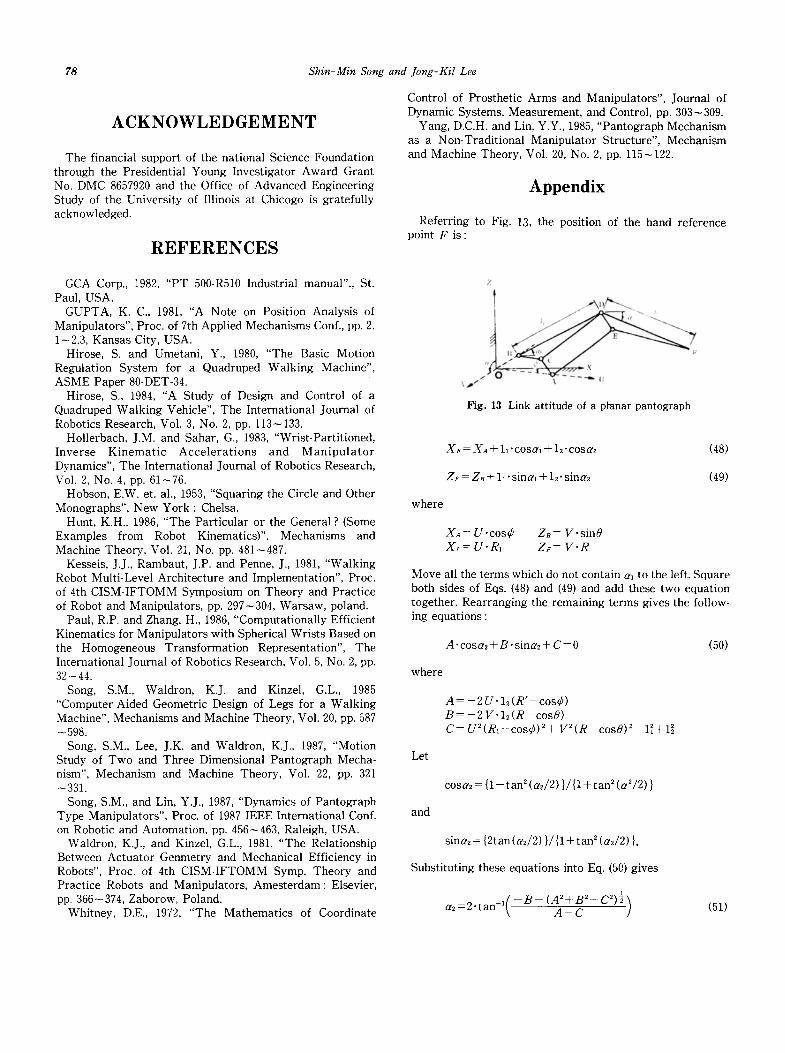
Referring to Fig. 13, the position of the hand reference point F is:
GCA Corp., 1982, "PT 500-R510 Industrial manual"., St. Paul, USA.
GUPTA, K. C., 1981, "A Note on Position Analysis of Manipulators", Proc. of 7th Applied Mechanisms Conf., pp. 2. 1-2.3, Kansas City, USA.
Hirose, S. and Umetani, Y., 1980, "The Basic Motion Regulation System for a Quadruped Walking Machine", ASME Paper 80-DET-34.
Hirose, S., 1984, "A Study of Design and Control of a Quadruped Walking Vehicle", The International Journal of Robotics Research, Vol. 3, No. 2, pp. 113-133.
Hollerbach, J.M. and Sahar, G., 1983, "Wrist-Partit ioned, Inverse Kinemat ic Acce le ra t ions and M a n i p u l a t o r Dynamics", The International Journal of Robotics Research, Vol. 2, No. 4, pp. 61-76.
Hobson, E.W. et. al., 1953, "Squaring the Circle and Other Monographs", New York : Chelsa.
Hunt, K.H., 1986, "The Part icular or the General ? (Some Examples from Robot Kinematics)". Mechanisms and Machine Theory, Vol. 21, No. pp. 481-487.
Kesseis, J.J., Rambaut, J.P. and Penne, J., 1981, "Walking Robot Multi-Level Architecture and Implementation", Proc. of 4th CISM-IFTOMM Symposium on Theory and Practice of Robot and Manipulators, pp. 297--304, Warsaw, poland.
Paul, R.P. and Zhang, H., 1986, "Computationally Efficient Kinematics for Manipulators with Spherical Wrists Based on the Homogeneous Transformation Representation", The International Journal of Robotics Research, Vol. 5, No. 2, pp. 32--44.
Song, S.M., Waldron, K.J. and Kinzel, G.L., 1985 "Computer-Aided Geometric Design of Legs for a Walking Machine", Mechanisms and Machine Theory, Vol. 20, pp. 587 -598.
Song, S.M., Lee, J.K. and Waldron, K.J., 1987, "Motion Study of Two and Three Dimensional Pantograph Mecha- nism", Mechanism and Machine Theory, Vol. 22, pp. 321 -331.
Song, S.M., and Lin, Y.J., 1987, "Dynamics of Pantograph Type Manipulators", Proc. of 1987 IEEE International Conf. on Robotic and Automation, pp. 456-463, Raleigh, USA.
Waldron, K.J., and Kinzel, G.L., 1981, "The Relationship Between Actuator Genmetry and Mechanical Efficiency in Robots", Proc. of 4th CISM-IFTOMM Symp. Theory and Practice Robots and Manipulators, Amesterdam: Elsevier, pp. 366-374, Zaborow, Poland.
Whitney, D.E., 1972, "The Mathematics of Coordinate
Z
l . .~ i~t . . .~ ~
/ r
Fig. 13 Link attitude of a planar pantograph
XF = Xa + 11"cosal + 15.cosa2 (48)
ZF = ZB + 11" sinai + 12" sina2 (49)
where
XA-- U .cos r ZB = V.s in0 Xr = U. R1 ZF = V" R
Move all the terms which do not contain a, to the left. Square both sides of Eqs. (48) and (49) and add these two equation together. Rearranging the remaining terms gives the follow- ing equations :
A" cosa2 + B" sina2 + C = 0 (50)
where
A = - 2 U . 1 2 ( R ' - c o s r B = - 2 V . 1 2 ( R - c o s O ) C = U2(R~-cos r V 2 ( R - c o s O ) 2 - 1 ~ + l ~
Let
and
cosa2 = {1- tan 2 ( a J2 ) }/{1 + tan s (a2/2) }
sine2 = {2tan (a2/2) }/{1 + t a n 2 (a2/2)}.
Substituting these equations into Eq. (50) gives
a2=2 . t a n 1( - B - (A2+B2-C2) �89 A - C ] (51)