experience of incinerator development in japan · data for 1975-1995 are for 5 year intervals. 4...
TRANSCRIPT

Experience of Incinerator Development in Japan
Katsuya KawamotoResearch center for Material Cycles and Waste ManagementNational Institute for Environmental Studies, Tsukuba, JapanVisiting Professor of Yokohama National University
Contents
IntroductionIncineration as a disposal method of municipal solid wastes (MSW) in Japan –Changes in the last two decadesInfluence of dioxin issues on the disposal of MSWGasification-melting process as a new incineration disposal of MSWFuture development
1
Introduction and overview -1
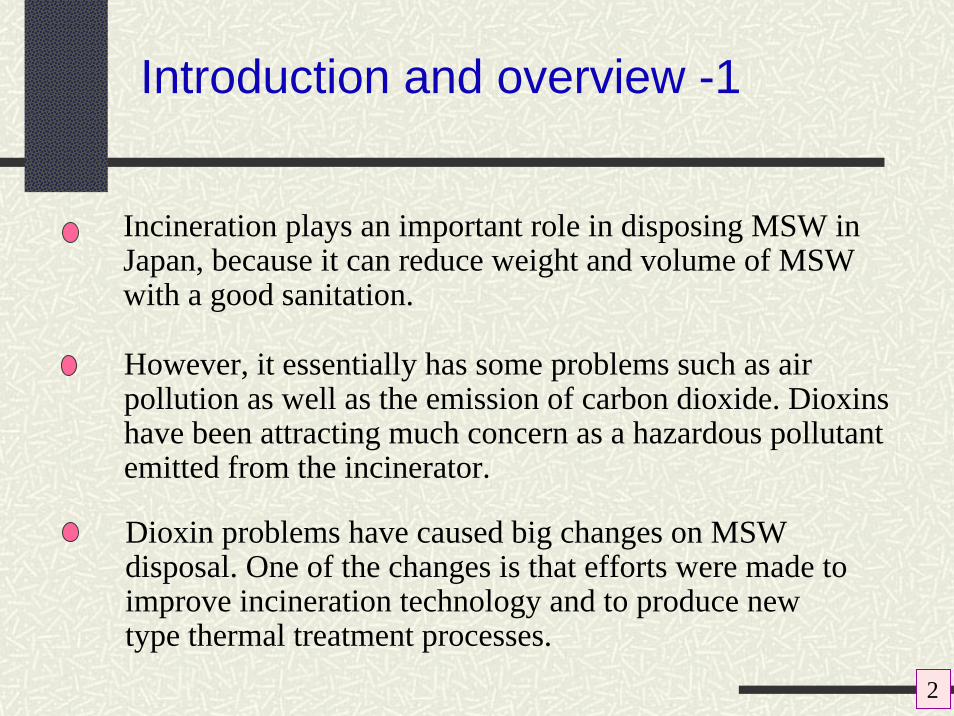
Incineration plays an important role in disposing MSW in Japan, because it can reduce weight and volume of MSW with a good sanitation.
However, it essentially has some problems such as air pollution as well as the emission of carbon dioxide. Dioxins have been attracting much concern as a hazardous pollutant emitted from the incinerator.
Dioxin problems have caused big changes on MSW disposal. One of the changes is that efforts were made to improve incineration technology and to produce new type thermal treatment processes.
2

Introduction and overview -2
Brand new incineration systems of pyrolysis/ gasification/melting processes have been introduced into Japan.
They have some distinctive features that suite for sustainable society, which are reduction of environmental pollutant loads and recovery of material resources from wastes.
There are a variety of movements for establishing a sound material-cycle society by many constituents.
3

3000
3500
4000
4500
5000
5500
1975
1980
1985
1990
1995
1996
1997
1998
1999
2000
2001
2002
2003
2004
Fiscal year
MSW
dis
char
ges
(104
tons
/yea
r)
30000
35000
40000
45000
Indu
stria
l was
te d
isch
arge
s (1
04to
ns/y
ear)
Municipal solid waste (MSW)
Industrial waste
3000
3500
4000
4500
5000
5500
1975
1980
1985
1990
1995
1996
1997
1998
1999
2000
2001
2002
2003
2004
Fiscal year
MSW
dis
char
ges
(104
tons
/yea
r)
30000
35000
40000
45000
Indu
stria
l was
te d
isch
arge
s (1
04to
ns/y
ear)
Municipal solid waste (MSW)
Industrial waste
Change over time in amounts of MSW and industrial waste
Data for 1975-1995 are for 5 year intervals. 4
1,000g/person·d
1,100g/person·d

Change of MSW in Japan
This figure also gives the breakdown of the treatment method of MSW.
0
1000
2000
3000
4000
5000
6000
Am
ount
(104 t)
1994 1995 1996 1997 1998 1999 2000 2001 2002 2003
Year
Incineration Resource recovery via treatmentImmediate resource recovery Immediate land disposal
5

0
2000
4000
6000
8000
10000
12000
1950 1970 1990 2010
Fiscal year
Hea
ting
valu
e(k
J/kg
)
Osaka Tokyo (wards) Yokohama
Change over time in heating value of waste (lower heating value)
6
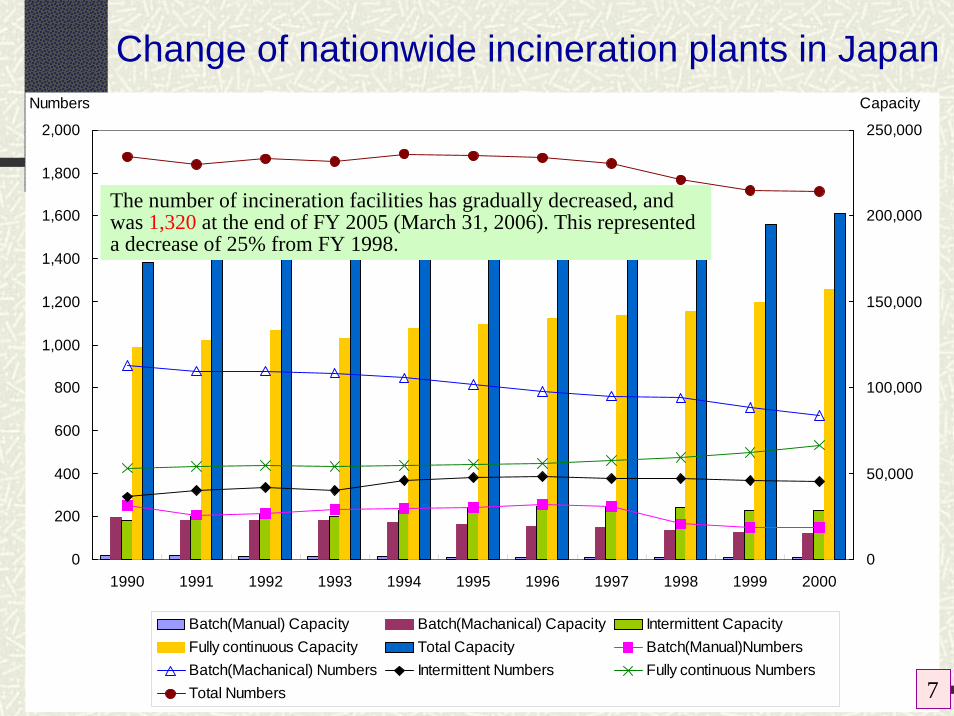
Change of nationwide incineration plants in Japan
0
200
400
600
800
1,000
1,200
1,400
1,600
1,800
2,000
1990 1991 1992 1993 1994 1995 1996 1997 1998 1999 20000
50,000
100,000
150,000
200,000
250,000
Batch(Manual) Capacity Batch(Machanical) Capacity Intermittent CapacityFully continuous Capacity Total Capacity Batch(Manual)NumbersBatch(Machanical) Numbers Intermittent Numbers Fully continuous NumbersTotal Numbers
CapacityNumbers
The number of incineration facilities has gradually decreased, and was 1,320 at the end of FY 2005 (March 31, 2006). This represented a decrease of 25% from FY 1998.
7

Regulations on air pollutants in Japan
PollutantSulfur oxides (SOx)DustHydrochloric acid (HCl)
Flue gas components
Nitrogen oxides (NOx)BenzeneTrichloroethyleneTetrachloroethylene
Hazardous air pollutants
Dioxins
Capacity of furnace
Criteria for newly constructed incinerator b)
(ng-TEQ/m3N)
Criteria for existing incinerator (ng-TEQ/m3
N)
> 4 t/h (96 t/d) 0.1 1
2-4 t/h 1 5
< 2 t/h 5 10
Regulation on dioxins (PCDDs, PCDFsand DL-PCBs) for incinerator of wastes a)Air pollutants from incineration a)
a) Based on “Law Concerning Special Measures against Dioxins”b) Facilities constructed after 16 Jan. 2000
a) Flue gas criteria are mainly determined based on “Air Pollution Control Law” 8
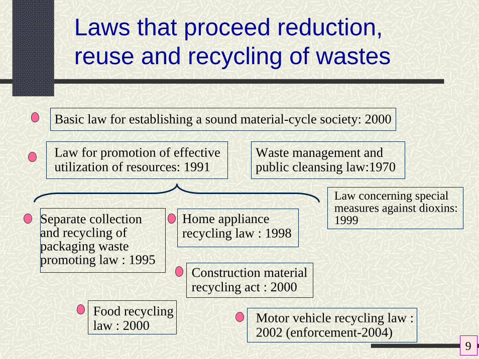
Laws that proceed reduction, reuse and recycling of wastes
Separate collection and recycling of packaging waste promoting law : 1995
Law for promotion of effective utilization of resources: 1991
Basic law for establishing a sound material-cycle society: 2000
Waste management and public cleansing law:1970
Home appliance recycling law : 1998
Food recycling law : 2000
Construction material recycling act : 2000
Motor vehicle recycling law : 2002 (enforcement-2004)
Law concerning special measures against dioxins: 1999
9

Transition of incineration treatment for MSW
In recent years, the dioxin problem brought about a particularly large change. In line with the movement toward a sound material-cycle society, heightened expectations were placed on resource recycling through the introduction of new methods such as the gasification and melting furnace and other technologies.
Functions and roles widely required in incineration treatment (have changed in response to the needs of the times…)
Appropriate treatment for sanitation
Weight/volume reduction
Reduction of environment impacts
Recycling and resource recovery
10

Incineration and incinerator
Drying/Pyrolysis
Gaseous combustion
Bottom ash
Complete combustion
Secondary air
Air for drying
Primary combustion air
Post combustion air
Flue gas + Fly ash
Ash melting furnace
Slag
Example of stoker type Incinerator
C + O2 = CO2H + 1/4O2 = 1/2H2O S + O2 = SO2NOx, CO, DXNs
to burn something until it is completely destroyed incinerate :
11

⑬
⑳
⑲22
23
⑱
21
⑯
⑰
⑮
Plant wastewater
Surplus heat use
⑭
⑫
⑧⑥
②⑩
⑪
⑨
⑤
④
③
⑦
Air flowWastewater flowGas flowCondensate flow
Steam flow
◆ ◆
Ash flow
Waste flow
Symbols
⑱Induced draft fan⑫Cooling tower⑥Ash pit
Chimney⑰Condensate tank⑪Boiler⑤Secondary forced draft fan
Steam condenser⑯Turbine-generator⑩Ash pusher④Primary forced draft fan
Wastewater treatment equipment⑮Steam receiver⑨Incinerator③Waste crane
⑳Catalytic reactor⑭Filter-type dust collector⑧Treated ash pit②Waste pit
⑲Steam-type gas reheater⑬Fly ash treatment equipment⑦Ash crane①Platform
21
22
23
①
Example of configuration of typical fully-continuous stoker-type incinerator
12

Important technical factors in incineration
Drying/Pyrolysis
Gaseous combustion
Bottom ash
Complete combustion
Secondary air
Air for drying
Primary combustion air
Post combustion air
Flue gas + Fly ash
Ash melting furnace
Slag
TemperatureTime (residence time)Turbulence (adequate mixing and stirring)
3 Ts :
Technical innovations, including improvement of the secondary combustion air injection method, advanced control using artificial intelligence, etc.
Large-scale fully-continuous facilities account for 40% of the total number of incineration facilities and more than 80% of treatment capacity.
Stoker type incinerator : 70 %
Fluidized bed type incinerator and gasification-melting furnace etc.: 30%
Number of incineration facilities
13
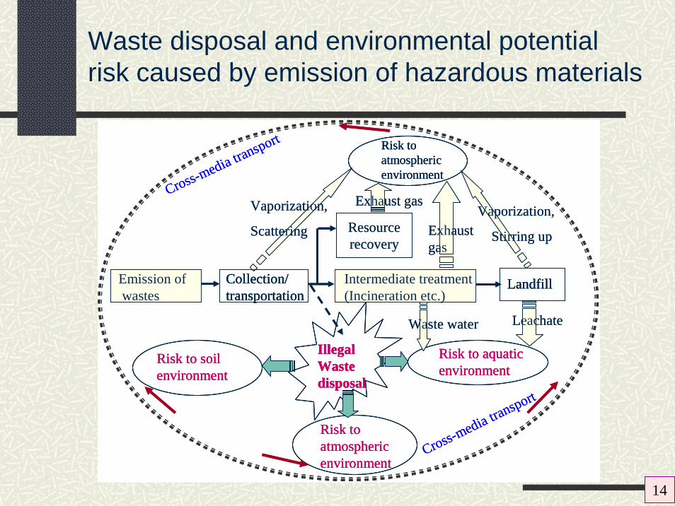
Waste disposal and environmental potential risk caused by emission of hazardous materials
Emission ofwastes
Collection/transportation
Intermediate treatment(Incineration etc.)
Landfill
Resourcerecovery
Risk to atmospheric environment
Risk to aquatic environment
Leachate
Exhaust gas
Illegal Waste disposal
Risk to soil environment
Cross-media transport
Cross-media transport
Vaporization,
Stirring up
Exhaust gas
Waste water
Risk to atmosphericenvironment
Vaporization,
Scattering
Emission ofwastesEmission ofwastes
Collection/transportationCollection/transportation
Intermediate treatment(Incineration etc.)Intermediate treatment(Incineration etc.)
LandfillLandfill
Resourcerecovery
Risk to atmospheric environment
Risk to atmospheric environment
Risk to aquatic environmentRisk to aquatic environment
Leachate
Exhaust gas
Illegal Waste disposal
Illegal Waste disposal
Risk to soil environment Risk to soil environment
Cross-media transport
Cross-media transport
Vaporization,
Stirring up
Exhaust gas
Waste water
Risk to atmosphericenvironment
Risk to atmosphericenvironment
Vaporization,
Scattering
14

Influence of the dioxin problem
The dioxins became an extremely large problem in Japan from around the mid-1990s and this had a direct effect on improvement of the element technologies of incineration treatment processes.
Regional MSW collection and treatment in areas spanning several municipal units (cities, towns, and villages
Encouraged efforts to create a recycling society
Improvement of combustibility : 3Ts
Power generation equipments w/higher efficiency
Improvement in flue gas treatment technologies such as changing dust collecting equipment to the bag filter
Total amount(g-TEQ/year)
Total Emissions of dioxins in Japan
15

Basic concepts of gasification and melting system
Low emission of dioxins because of high temperature combustionLow air ratio combustion and simplification of flue gas treatment systemMelting only by own possessing energy (It does not need to put energy from outside.)Recycling of valuable materials (Fe and Al) in high quality because of reductive atmosphereMinimization of the quantity and volume of residues that are transferred to landfill site
ガス化-溶融方式
Fe and Al can be recovered in the state not to be oxidized.
Ash is highly reduced and can be changed to resources.
Dioxins can be highly reduced because of high temperature.
Low air ratio combustion→ Simplification and minimization of flue gas treatment
Pyrolysis gasifier
Melting furnace
Dust separator
De-NOxequipment
SlagIron, Aluminium
MSW
Gas
Steam turbine
Power generator
Stack
Fly ash
Boiler
16

Classification of incineration and gasification/melting system
Gasification type Melting furnace type Manufacturer in Japan
Shaft furnace (Melting is done in the same furnace.)
· Nippon Steel Engineering Co., Ltd.· JFE Engineering Corporation
Kiln type Circular flow melting · Mitsui Engineering & Shipbuilding Co., Ltd.· Takuma Co., Ltd.
Fluidized bed Circular flow melting· Ebara Corporation· Kobelco Eco-Solutions Co., Ltd.· Hitachi Zosen Corporation· Others
Stoker typeFluidized bed type
Rotary typeGasification melting facility Shaft furnace type
Gasification reform type Shaft furnace type
Kiln type
Fluidized bed type
Kiln typeFluidized bed type
Integrated type
Separate type
Integrated type
Separate type
Incineration plant
17

Change of the number of gasification/ melting plant in operation
0
20
40
60
80
100
1998
1999
2000
2001
2002
2003
2004
2005
2006
Year
Num
ber o
f pla
nt
Gasification/gasreforming systemKiln gasification
Fluidized bedgasificationShaft furnace
18

Shaft furnace type gasification/ melting system
Water crusher
To melting furnace
Precrusher
Platform
Waste craneCokeLimestone
Collected dust detoxifying system
Induced draft fan
Steam turbine generator
Waste pit スラグ
メタル
Flow of solid wasteFlow of airFlow of exhaust gas
Flow of molten materialsFlow of ashesFlow of steam
Melting furnace
Combustion chamber
Boiler
Exhaust gas temperature adjuster
Bag filter
Catalytic reactor
Stack
Molten materials
Magnetic separator
SlagMetal
19

Kiln type gasification/melting system
Exhaust gas
Pyrolysis residue sorter
G
Alkali agent
Mixer
Mixture
MSW
SlagAluminumIron
Reactant
Drum hot gas precipitator
Drum heating gas circulating blower
Waste crusher
Heavy metal
fixativeSlag conveyor
Carbon & molten fly ash silo
To high-temperature combustion melting
Primary bag filter
Steam gas reheater
Catalytic de-Noxreactor
Induced draft fan
Stack
Exhaust gas recirculation blower
Steam turbine
Boiler
Pyrolysis gas incinerator
Air preheaterForced draf t fan
Suction blower
High-temperature combustion melting furnace
Pyrolysis drum
Secondary bag filter
Gas cooler
20
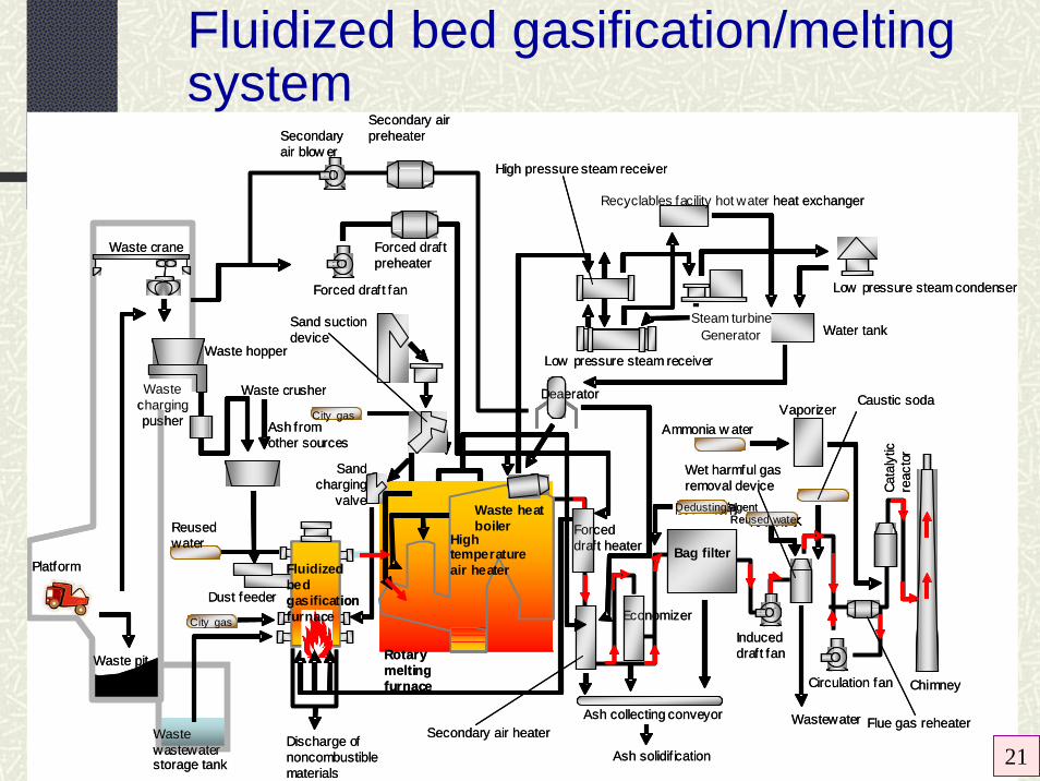
Platform
Waste crane
Waste pit
Waste wastewater storage tank
City gas
Reused water
Fluidized bed gasification furnace
City gas
Waste heat boiler
High temperature air heater
Rotary melting furnace
Deaerator
Secondary air heater
Bag filter
Water tank
Low pressure steam condenser
Steam turbineGenerator
Recyclables facility hot water heat exchanger
High pressure steam receiver
Low pressure steam receiver
Economizer
VaporizerCaustic soda
脱じん助剤Dedusting agent再利用水Reused water
Chimney
Ammonia w ater
Flue gas reheater
Circulation fan
Induced draft fan
Ash collecting conveyor
Discharge of noncombustible materials
Wastewater
Ash solidif ication
Secondary air blow er
Secondary air preheater
Forced draft preheater
Forced draft fan
Sand charging
valve
Waste hopper
Waste charging pusher
Waste crusher
Ash from other sources
Dust feeder
Wet harmful gas removal device
Sand suction device
Forced draft heater
Cata
lytic
re
acto
r
Fluidized bed gasification/melting system
21

Performance of gasification/melting furnace system : Relationship between amount of waste processed and slag production
A~G shows each plant surveyed. 22

Next-generation stoker furnace
~1000 oC
Purification of exhaust gas and ash, and recycling
High-efficiency exhaust gas treatment
Improvement of heat recovery rate
Increased boiler temperature and pressure
Waste
Air/exhaustgas
Combustion chamber
Boiler
To exhaust gas treatment system
Fly ash
Heating by steam
Downsized exhaust gas treatment system Air
Incinerator bottom ash
Integration of systems (ash melting, etc.)
Improvement of combustionperformances
Lower air ratio/increased oxygen concentration in combustion air
Blowing heated air
Circulation (recirculation) of exhaust gas
Advanced grate cooling
Application of advanced control technology
- Concept and characteristics of the next-generation stoker furnace
23

Power generation by incineration“Refuse (Waste) to energy”
Use of residual heat in waste incineration plantsX
Boiler
Exhaust gas treatment system
Stack
Combustor
Waste feed
G
Fuel
Air
G
Condenser
Feed water
Steam
Steam turbine
Gas turbine generator
: Steam flow
: Exhaust gas flow
: Generator G
Superheater
Incinerator
Use of residual heatU s e o fresidual heat Total Hot
water Steam Power generation Other
Residual heat is not used.
Number of plants
995*
(1,035)923
(966)244
(244)271
(263)79
(85)401
(455)
Combined and repowered system for power generation in incineration facility
*Value of 2003.The numbers may be counted repeatedly
and the ones in the parentheses indicate data for 2002.
24

Relationship between amount of waste processed and power generation
0
1,000
2,000
3,000
4,000
0 5,000 10,000 15,000
ごみ処理量(t/月)
発電
電力
量(M
Wh/月
)
ABCDEFG
Amount of waste processed (t/month)Gen
erat
ed p
ower
(MW
/H/m
onth
) Current status on power generation in gasification/melting plant
Based on a detailed investigation conducted for 7 facilities
250 kWh/t-MSW
25

Exhaust gas treatment technologyTypical recent exhaust gas treatment systems
(a)
(b)
(c)
Incinerator Boiler Gas cooler
Lime and activated carbon or auxiliary agent
Bag filter Stack
Incinerator Boiler Gas cooler
Melting furnace
Gas cooler Dust collector
Ammonia
Re-heater
Catalytic NOx removal tower
Bag filter
Gasification melting furnace
Gas cooler
Re-heater
Bag filter (1)
Ammonia Activated carbon or auxiliary agent
Bag filter (2)
Fly ash
Alkaline agent
Lime and activated carbon or auxiliary agent
Stack
Boiler Catalytic NOx removal tower
Stack
26
High efficiency dust removal
Low temperature (150-200ºC)

Gasification and gas reforming technology
Gasification/melting system succeeds in the utilization of potential energy of MSW. However, chemical species such as C and H are not utilized as materials.
Gas reforming process converts pyrolysis gas to H2, CO, CO2and CH4 etc.. Especially, H2 can be utilized in a fuel cell.
Hydrogen energy attracts a great concern because it can be applied to fuel cell and may produce a new energy system in a future society.
27

Thermoselect systemTM (JFE Engineering)
Pit
Wastes
(6)High-speed gas cooling device
(5)Gas reformer
Hightemperature
reactor
1200oC
Press
(1)Waste compressor
Oxygen
PSA (3)Gasifier/Melting chamber
Drying/Degassing
Homogenization camber
(4)Slag/Metal homogenization chamber
Compositionexample (Vol%)H2 : 35%CO : 25%CO2 : 35%
(7)Gas purifier Washing DesulfurizationDehumidifition
(2)Dryer and pyrolyzer
SlagMetal pit
Salt mixing device
Mixed saltMetallichydrates
(8)Water treatmentdivice
Reusable water
SulfurPurified
synthesized gas
Process watertreatment device
NaOH
28
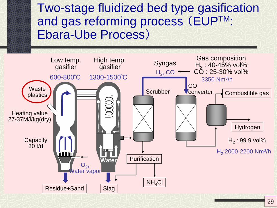
Two-stage fluidized bed type gasification and gas reforming process (EUPTM: Ebara-Ube Process)
Wasteplastics
Heating value27-37MJ/kg(dry)
Capacity30 t/d
Low temp.gasifier
600-800ºC
Combustible gas
Hydrogen
H2 : 99.9 vol%
H2:2000-2200 Nm3/h
High temp.gasifier
1300-1500ºC
SyngasH2, CO
Gas compositionH2 : 40-45% vol%CO : 25-30% vol%
3350 Nm3/h
Purification
NH4ClSlagResidue+Sand
O2,Water vapor
Water
ScrubberCOconverter
29

Gasification/gas reforming plant installed in a plant of Showa Denko K.K.
Height : 70 m (!)
Stock tower of raw material
Gasification furnace/gas reforming furnace
Raw material:Waste plastics
Amount treated:195 t/d
in plan (64,000 t/y)
Major gas components:H2, CO,CO2Gas formation amount:200,000m3
N/d
Operated from April, 2003
Type:EUP
Use of gas:H2 is used as a raw material of ammonia synthesis. CO2 is supplied to another manufacturer. 30

Development concept of gasification and reforming system
Basic concept of R & D on gasification/reforming technology conducted in National Institute for Environmental Studies Japan
Molten Carbonate Fuel Cell (MCFC)
Refiner
Point 2 : Configuration of suitable gasification operating conditions
Point 3 : Confirm the catalytic performance on hydrogen conversion, furthermore on reducing emissions of by-products.
Pyrolysis gas
H2
COCO2H2,CO
Point 1 : To verify the feasibility of the disposal of various kinds of solid waste by gasification
MSW WastePlastics
Aims of this study• To establish an efficient hydrogen production process.• To reduce emissions of pollutants and by-products.
OxygenSteam
Applica-tion ofCatalystsBiomass
Steam Oxygen
orSolid Oxide Fuel Cell (SOFC)
Reformed gas
31

Recent trial in Japan
What is attracting most attention recently in waste treatment is the use of methane fermentation. It is being studied to produce methane (biogas) by taking advantage of the presence of food waste with a high water content, and to use it directly as an energy source or reform it into hydrogen.
Biogas + incineration Energy efficiency* = 25%
Waste Garbage Methane fermentation Biogas Gas engine
84MWh Power
466MWhTotal generated
power
382MWh PowerIncineration
Residue
Combustible materialResidue
Incineration Energy efficiency* = 21.7%
Waste Incineration 403MWh
Total generated power
** Energy efficiency = (Generated power x 3,600) / (Heating value of waste)
1,000ton6.7MJ/kgMoisture 50%
360ton1.9MJ/kgMoisture 80%
49ton3.3MJ/kg
1,000ton6.7MJ/kgMoisture 50%
640ton9.4MJ/kg
689ton9.0MJ/kgMoisture 36%
Example of trial calculation of energy recovery effect by methane fermentation process
A combination of incineration with methane fermentation technology is expected to be used in future waste treatment.
An increase in generated power is expected based on estimates for the case in which all of the waste produced is incinerated and for the case in which some food waste is used for methane fermentation.
32
Conclusions and future direction
In this context, gasification and melting furnace system will be a promising way for the disposal of MSW and resource recovery.
Further, gasification and reforming technology may be an expected technology as a material and energy recovery system from solid wastes including biomass.
Incineration has been a core technology for MSW treatment in Japan. The performance of rapidly reducing the amount of MSW is reliable.
However, it needs effective flue gas treatment and further it becomes important to meet the needs of the times, such as recovery of energy and recycling of resources, and to make good use of incineration.
33