chapter xiii. incineration and thermal conversion · chapter xiii. incineration and thermal...
TRANSCRIPT
CHAPTER XIII. INCINERATION AND THERMAL CONVERSION
This chapter describes thermal conversion systems used for solid waste management. For the purpose of the discussion, the chapter has been divided into two major sections – Incineration and Pyrolysis.
A. Incineration
A1. INTRODUCTION
The first attempts to dispose of urban refuse through combustion in a furnace are reported to have taken place in the north of England in the 1870s [1]. By the turn of the century, emphasis was placed on the development of furnaces capable of burning solid wastes. During this time, a number of communities found incineration to be a satisfactory and sanitary method of waste disposal. The reason for the satisfaction lay in the fact that the main objective was to achieve maximum volume or weight reduction. Little or no concern was had for energy recovery or for control of air pollution from incinerators. The situation changed completely in the 1960s in that the majority of incinerators in the United States were closed down, primarily because of excessive particulate emissions. However, the popularity of incineration continued undiminished in Western Europe and often was made to include energy recovery.
Throughout this chapter, the terms “incinerator” and “incinerator system” are used to describe equipment and systems that combust solid waste or fuels derived from solid wastes. Thus, as used herein, the above terms are synonymous with “combustor” or “combustion systems”. While, in earlier times, the term “incinerator” connoted uncontrolled combustion, the incinerators of today have a much higher degree of process control.
A2. PRINCIPLES
Incinerators may be classified in a variety of fashions: by type and form of the waste input; by the throughput capacity (with or without heat recovery); by the rate of heat production (for systems with energy recovery); by the state in which the residue emerges from the combustion chamber (e.g., slagging); and by the shape and number of furnaces (e.g., rectangular, multiple). The key system elements involved in the incineration of urban wastes are: 1) tipping area, 2) storage pit, 3) equipment for charging the incinerator, 4) combustion chamber, 5) bottom ash removal system, and 6) gas cleaning equipment (i.e., air pollution control system). If energy is to be recovered, a boiler is included.
Combustion air may be classified either as “underfire” or as “overfire” air. Underfire air is that which is forced into the furnace through and around the grates. Overfire air is forced into the furnace through the sides or the ceiling. Overfire air typically is introduced through jets located at specific points in the furnace. It is used to regulate and complete the combustion of combustible gases evolved by the thermal reactions that are occurring in the lower part of the furnace. The flow of air and combustion gases through the furnace can be controlled by means of forced draft and induced draft fans. The forced draft fan, as its name implies, forces air into the furnace, while the induced draft fan draws the air. Both types are used in modern combustion units. Forced draft fans provide for the central overfire and underfire air, and induced draft fans for the exhausting of the flue gases.
The furnace (i.e., combustion chamber) is the essential element of an incineration system. Types of furnaces include rectangular, cylindrical, and multi-chamber. The size and shape of a furnace
303

usually are determined by the manufacturer, and are based upon a number of parameters, including: solids and gas flow rates, residence time, combustion temperature, and depth of ash bed. In some cases, secondary combustion chambers are included as part of the design. They are connected to the primary chamber, and their main function is to provide the proper conditions needed to complete the combustion process.
Generally speaking, two types of solid residues are generated from incineration: 1) bottom ash, and 2) fly ash. The two residues collectively are known as “ash” and, in the case of industrialised nations, typically are equal to approximately 20% to 40% (by wt) of the incoming solid waste (besides the inherent ash content of MSW, fly ash can also contain additional mass by virtue of chemical reagents used to treat the inherent fly ash). Systems must be included in the facility design to handle and treat the two ash streams. Depending on conditions, the bottom ash and fly ash may be processed separately or in combination. The ash that is produced from incineration is hot and must be cooled prior to disposal. The normal method of cooling is quenching in water. After quenching, the ash is dewatered to facilitate storage or landfilling on the incinerator site or transport to a remote disposal site. Both the quench water and the ash must be treated and disposed properly.
Taken in combination, the grate system, bottom ash removal, and quenching and dewatering system compose the material handling system for the bottom ash. Historically, the bottom ash handling system has been one of the systems in an incineration facility that has experienced, and is particularly susceptible to, extraordinary wear and tear and frequent breakdowns.
Years ago, incinerators were designed to burn waste that had a low heating value. The reason was primarily to accommodate wastes with a high moisture content. Consequently, features were incorporated that were designed to: 1) dry and ignite the refuse, and 2) deodorise the off gases. Little or no waste heat was available for energy export. As the composition of municipal waste in industrially developed countries changed (i.e., substantial paper and plastic content, small putrescible fraction), the heating value of the solid waste increased. To accommodate the increase, the designers of modern incinerators include in their designs provision for the utilisation of excess energy. This is done by introducing a waste heat boiler for steam generation.
In industrialised nations, incineration systems must have complex air pollution control (APC) systems in order to meet the required limits for protecting the quality of the ambient air and human health. The complexity is a result of the fact that modern APC systems include provisions for controlling a number of pollutants to very low concentrations (e.g., parts per million or per billion). The provisions include control and manipulation of the combustion process itself within the combustion chamber and the use of post-combustion techniques, including the use of chemical reagents and of special mechanical and electrical systems to process the combustion gases [10]. The principal pollutants that are controlled in industrial countries are listed in Table XIII-1, along with the typical methods of control and levels of pollutant reduction. Because of their complexity, modern APC systems can account for up to 30% of the capital cost of incineration systems.
In the last 10 to 15 years, considerable research and development effort has been expended on “trace” air pollutants formed as byproducts of solid waste combustion, the relevant chemistry, and methods of control [14]. Examples of these trace pollutants are mercury, and dioxins and furans.
A3. TYPES of incinerators
Three types of incinerators, modular (small capacity, less than about 300 Mg/day), large-capacity stoker, and fluidised bed, are discussed in this chapter. (As will be described subsequently, a
304

stoker is a system of grates.) These three types of incinerators will satisfy the majority of applications of incineration (with or without heat recovery) that will exist in many of the developing nations for the next several years. Additionally, large-capacity stoker systems have been subdivided into two subtypes due to the different forms of solid waste that are combusted: 1) municipal solid waste, and 2) refuse-derived fuel.
Table XIII-1. Air pollutants from solid waste incineration and methods of control
Pollutant Control Methods Typical Reduction (%)Oxides of nitrogen (NO2) • Selective catalytic reduction
• Selective non-catalytic reduction
• Flue gas recirculation • Combustion control
10 to 60
Acid gases (SO2 and HCl) • Wet scrubber • Dry scrubber • Fabric filter • Electrostatic precipitator
50 to 85 SO2 75 to 90 HCl
Carbon monoxide (CO) • Combustion control 50 to 90 Heavy metals • Dry scrubber
• Fabric filter • Electrostatic precipitator
70 to 95
Particulates • Electrostatic precipitator • Fabric filter
95 to 99.9
Toxic organics (including dioxins and furans)
• Combustion control • Combination of dry scrubber
and fabric filter
50 to 99.9
Source: Reference 10.
A3.1. Modular (small-capacity) incinerators
Modular combustion systems are so named because each combustion unit is of relatively low throughput capacity in comparison to the typical capacity of a massburn or RDF incinerator. As used here, a unit, or module, consists of one primary combustion chamber (i.e., a chamber in which the solid waste is converted to gaseous compounds). To achieve an equivalent processing capacity of a typical large-capacity, stoker-type massburn or RDF incinerator, multiple modules would be required; thus, the derivation of the term “modular” for this type and capacity of combustion technology.
The charging chamber of a modular incinerator is typically loaded by a front-end loader. Wastes are fed into the primary combustion chamber by a hydraulic ram. Wastes are moved through the primary combustion chamber of large-capacity modular incinerators by moving grates, usually reciprocating grates. A modular incinerator (with or without an energy recovery system) also has a separate, secondary combustion chamber dedicated to completing the combustion of the partially oxidised gases produced in the primary combustion chamber.
An illustration of a modular incinerator is shown in, and its key components are presented in, Figure XIII-1. A photograph of a modular incineration facility is shown in Figure XIII-2.
305

Modular units typically are designed to process up to about 300 Mg of waste per day. As mentioned earlier, the design of most modular incinerators includes a primary and a secondary combustion chamber and provides for the introduction of the air needed to attain complete combustion. Thus, sometimes they are termed “controlled air modular incinerators”.
Loading Hopper
PrimaryCombustion Chamber
SecondaryCombustion Chamber
Dump Stack
Energy Stack
Hot Gas Manifold
Boiler
Ash Discharge
Figure XIII-1. Illustration of modular combustion unit used for residential and commercial MSW and for selected industrial wastes
Some designs also incorporate energy recovery equipment. The majority of modular incinerators usually can function quite well when burning commercial and industrial wastes. However, some designs and facilities have encountered an assortment of difficulties in processing unsorted municipal solid wastes. The difficulties usually presented themselves in the form of unreliable operation of the ash handling system and of unacceptably high wear-and-tear on the equipment. Small-capacity modular incinerators are commonly used to combust solid wastes from a single generator, e.g., a hospital (medical wastes) or manufacturing facility. Small modular incinerators that process a few Mg per day commonly are supplied as batch systems without provisions for automatic feeding of wastes or for ash removal.
A modular incinerator/steam production facility of moderate capacity for MSW can cost from US$75,000 to US$100,000 per Mg of daily capacity.
A3.2. Large-capacity stoker systems
A stoker is a system of grates that moves the solid fuel through the combustion chamber. A variety of types of stokers are available. Typically, the grates in large-capacity massburn incinerators are movable (vibrating, rocking, reciprocating, or rotating) to provide agitation to the wastes, thereby promoting combustion. The movement also serves to remove the residue from the furnace. The stoker commonly employed in large incinerators designed to combust RDF is a
306

“travelling” grate; a travelling grate consists of a set of hinged grate sections that are configured as a conveyor belt.
Two examples of stokers used in massburn incinerators are shown in Figure XIII-3. In the case of massburn systems, the primary combustion of the waste occurs on the grate.
Courtesy: CalRecovery, Inc.
Figure XIII-2. Modular combustion facility
307

Gas
Waste FeedHopper
WasteFeeder
Moving BarsFixed Bars
Combustion GrateExtractor
Air
Ash
SolidWaste
Gas
RollerGrates
Air
Ash
Figure XIII-3. Grate systems used in massburn MSW combustors
An example of a grate system for an incinerator designed to burn RDF is shown in Figure XIII-4. In the case of an RDF incinerator, a substantial portion of the combustion of the RDF occurs while the fuel is in suspension or falling toward the grate. Thus, only a portion of the combustion of the fuel occurs on the grate itself. In the case of all grate systems, air is introduced below the grate in order to: 1) cool the grate and, therefore, maintain the temperature of the grate below its maximum design temperature; and 2) provide a supply of combustion air to the waste burning on the grate (i.e., underfire air).
Ash Bed
Figure XIII-4. Travelling grate system used in RDF-fired incinerators
Large-capacity stoker systems that combust raw MSW are commonly referred to as “massburn” incinerators. On the other hand, as the name implies, RDF combustion systems are designed to burn a combustible mixture of materials that is recovered from MSW. Another name commonly used to describe RDF is “prepared fuel”. The definition of two subtypes in the case of large-capacity stoker combustors is appropriate due to some important differences between the two types of feedstocks (i.e., raw MSW and RDF) with respect to combustion system design. Among
308

the more important distinctions, MSW has a lower heating value and higher ash content than would be exhibited by an RDF recovered from the same MSW. Other distinctions between MSW and RDF and between different qualities of RDF are discussed in Chapter XII, Production of Refuse-Derived Fuel.
A3.2.1. Massburn incinerators
In a typical massburn incinerator operation, the MSW to be burned is unloaded from the collection vehicles onto the tipping floor or directly into a storage pit. A pit is included so that sufficient solid waste can be stored to permit a continuous operation of the incinerator (i.e., 24 hr/day, 7 day/wk). The pit also serves as an area in which large non-combustible materials can be removed, and the wastes can be blended to achieve a fairly uniform and constant charge. From the pit, the waste is transported to a charging hopper. Charging hoppers are used for maintaining a continuous feeding of waste into the furnace. Massburn incinerators do not use pneumatic or mechanical systems for injecting or charging the waste into the combustion chamber. (Mechanical and pneumatic injection systems are typically used when RDF is the feedstock.) Wastes fall from the hopper onto the stoker (i.e., grate system) where the combustion takes place [2].
An illustration of a large-capacity massburn incinerator and its key components is shown in Figure XIII-5. A photograph of a massburn incinerator facility is shown in Figure XIII-6.
A modern massburn/electricity production facility having a capacity in the range of 800 to 2,500 Mg/day may cost approximately US$90,000 to US$135,000 per Mg of daily capacity.
Crane
ChargingChute
WasteStorage
Pit
WaterwallBoiler
Grates
QuenchTank
Ash
DryScrubber
Baghouse
Fly AshInduced
DraftFan
Stack
Figure XIII-5. Key Components of a massburn incinerator system with energy recovery
309

Courtesy: CalRecovery, Inc.
Figure XIII-6. Massburn combustion facility
A3.2.2. RDF-fired incinerators
Large RDF-fired incinerators are similar in overall design to massburn units. However, key distinctions exist between the designs. As mentioned previously, RDF incinerators usually have a travelling grate at the bottom of the furnace, as opposed to the agitating form of grates used in most massburn incinerators. Secondly, since RDF has a finer size distribution than raw MSW, the charging system is different. RDF combustion systems commonly employ a ballistic type of feeding system, i.e., the fuel is injected into the combustion chamber above the grate at a relatively high velocity using mechanical or pneumatic injection, or a combination of the two injection methods. On the other hand, as noted above, massburn incinerators are fed by gravity through a charging chute. An illustration of an RDF incinerator and its key equipment is presented in Figure XIII-7. A photograph of an RDF combustion facility is shown in Figure XIII-8.
310

WaterwallBoiler
Ash
DryScrubber
Baghouse
Fly AshInduced
DraftFan
Stack
TravellingGrate
RDFStorage
OverfireAir
Ash Quench
Figure XIII-7. Key features of a dedicated RDF incineration system with energy recovery
Courtesy: CalRecovery, Inc.
Figure XIII-8. RDF combustion facility
A modern RDF/electricity production facility, including pre-processing and combustion systems, with a capacity in the range of 1,000 to 2,000 Mg/day, can cost in the neighbourhood of US$100,000 to US$150,000/Mg/day.
311

A3.3. Fluidised Bed Incinerators
While fluidised beds can be used in pyrolysis (or thermal gasification) systems, which operate in oxygen-deficient conditions, their use in incineration systems under oxidising conditions only is discussed in this book. In a fluidised bed incinerator, the fuel, e.g., solid waste, is combusted within a chamber that contains a high temperature zone (i.e., bed) of a fluidised, granular, non-combustible medium, such as sand. The particles of the medium are suspended (fluidised) within the combustion zone through the nullification of the downward acting gravitational force by the upward acting aerodynamic lifting force that is imparted by the combustion air stream that is made to permeate the bed. The concept of the design is that complete or near complete combustion (i.e., no or little unburned carbon in the ash residue) of the solid fuel particles is facilitated by their intimate contact with many sites (i.e., grains of the medium) of high temperature and by the high surface-to-volume ratio. Also, because of this design concept, a particulate form of solid waste is the optimum. Thus, RDF is the usual form of solid waste that would be supplied to fluidise bed combustion units. For reasons of cost and for appropriate thermal characteristics, the optimum choice of medium is usually sand.
Fluidised bed (FB) combustion technology is appropriate for the efficient thermal conversion of a number of solid fuels, including coal. Consequently, the technology is suited for combustion of RDF, or for co-firing of RDF and coal. The experience with combustion of municipal solid waste in FB reactors is currently limited primarily to research and development; although, there is some limited commercial history as discussed below. As of this writing, most commercial fluidised bed conversion systems operate at approximately atmospheric pressure and combust coal or wood. Certain potential advantages have been offered for the operation of fluidised bed systems at elevated pressure (i.e., pressurised fluidised bed) as opposed to atmospheric pressure, such as higher thermal efficiency. However, commercial application of pressurised FB technology to combustion of solid waste is some years into the future. One reason is the problems attending the feeding of a solid waste feedstock into a system at elevated pressure [11].
Two basic types of fluidised bed designs are commercially available: bubbling bed and circulating bed. The main difference in the designs is the higher air supply velocity used in the circulating bed technology. As the name implies, in a circulating bed unit, the bed medium is captured from the high-velocity combustion gas stream exiting the combustion chamber and subsequently cleaned of ash particulates and recycled into the bottom of the bed zone. In a bubbling bed system, the gas velocities are maintained at a low level so that the bed medium is maintained in the combustion chamber. Circulating bed designs have an economic advantage over bubbling bed designs when the energy output requirements are greater than 45,000 kg steam/hr [12]. The majority of commercial fluidised bed systems combusting low-grade fuels are of the circulating bed design [13]. An illustration of a circulating fluidised bed system is shown is Figure XIII-9.
The interest in the use of FB technology for the combustion of solid waste stems from several factors: 1) the performance of the combustion process is relatively insensitive to the flow rate of the feedstock (i.e., it has a high turndown ratio); 2) compared to standard incinerators, the combustion temperatures are relatively low and, therefore, emissions of nitrogen oxides are subjected to inherent control during the combustion reaction; and 3) reagents in solid form can be incorporated among the inert bed particles and used to control acid gas emissions. These methods of control ease, but do not necessarily eliminate, the need for exhaust gas treatment in cases where low concentrations of pollutants are desired or required by regulation.
312

Ash
DryScrubber
Baghouse
Fly AshInduced
DraftFan
Stack
CycloneSeparator
Air
RDF
FluidisedBed
Figure XIII-9. Key features of an RDF-fired circulating fluidised bed combustion system with energy recovery
As mentioned earlier, the use of fluidised combustion for thermal conversion of solid waste has seen limited application in the past. The limited commercial applications have primarily combusted RDF and a supplemental fuel, e.g., sludge, coal, or wood. A limited resurgence of interest and application of combustion of RDF in dedicated fluidised bed combustors occurred in the United States in the mid 1990s.
For fluidised bed systems to be effective, the combustion conditions within the fluidised bed must be carefully controlled. As is the case with any type of combustion system, control is easiest to maintain continuously and effectively at the set point if the solid fuel is a homogeneous mixture (i.e., possesses uniform characteristics, e.g., composition, bulk density, and particle size). Homogeneity is especially important in the case of fluidised bed technology due to its particular sensitivity to fuel characteristics. In the case of this technology, RDF is not the optimum feedstock given its heterogeneity (i.e., non-uniformity of characteristics). On the other hand, one of the potential benefits of the fluidised bed is its ability to accommodate variations in fuel flow rate while maintaining a specified level of performance.
A modern RDF-fired fluidised bed/electricity production facility (pre-processing and combustion systems), with a capacity in the range of 800 to 1,000 Mg/day, can cost in the range of US$135,000 to US$190,000/Mg/day.
B. Pyrolysis
Pyrolysis is a process in which organic matter is broken down at high temperatures in the absence or near absence of oxygen into products that may be gaseous, liquid, or solid in form, or as a collection of all three forms. The system pressure influences the reaction and, therefore, the characteristics of the products of the reaction. Most of the products are organic and, therefore, combustible and are potential energy sources.
Strictly speaking, pyrolysis is the high-temperature thermal conversion of organic material in an environment devoid of oxygen. Two other thermal conversion processes are similar but not identical to pyrolysis: thermal gasification and liquefaction. Thermal gasification is a thermal conversion process that occurs in a high-temperature, sub-stoichiometric environment, i.e., insufficient oxygen is present in the reaction to convert all organic carbon to carbon dioxide.
313
Liquefaction is similar to thermal gasification. However, in the case of liquefaction, the reactions are shifted in favour of a high yield of liquid byproducts. Since the three processes have many similar characteristics, for the purpose of this discussion, they are lumped together under the term “pyrolysis”.
Pyrolysis differs from incineration in that it is an endothermic reaction and takes place in an oxygen-free or low-oxygen atmosphere. Because it is endothermic, a considerable amount of energy input is required to attain the high temperatures required to volatilise the organic compounds.
An interest in the pyrolysis of municipal solid waste began in the late 1960s. The interest was based on the reasoning that since municipal solid waste is typically at least 60% organic in nature, it should be a raw material well suited for pyrolysis. During the mid-1970s, the interest and the potential of pyrolysis as a method of producing energy reached their peak. As a consequence, a number of studies were conducted in the United States and in Europe, and a few were expanded to encompass the construction and operation of commercial-size demonstration plants. In the middle to late 1970s, a combination of technical problems and unfavourable economics associated with MSW pyrolysis resulted in a drastic lowering of the interest and expectations for the technology. The lack of interest persists as of this writing.
Certainly, the combination of technological difficulties and poor economics would make pyrolysis a dubious undertaking by a developing nation. Nevertheless, pyrolysis is described herein in order to provide the decision-maker with the background information required to arrive at a rational decision as to the advisability of using pyrolysis as a method of resource recovery. The most likely recoverable resource would be energy, at the time of this writing, but the potential of synthesis of chemical feedstocks, e.g., methanol, is not ruled out. Chemical feedstock recovery, although economically unfeasible at this time, is technically achievable.
B1. PRODUCTS
The gases produced are principally CO, CO2, H2, and water vapour. The liquids consist of pyrolytic oil, highly viscous tars, and oxygenated organics in water. The solids are collectively designated as “char”.
The quantity and composition of the products of pyrolysis are functions of the composition of the raw material (“input”, “charge”), and of the temperature and pressure applied in the process. The higher the temperature, the greater is the yield of gas, whereas that of the liquids and char is correspondingly less.
The relative concentrations of the three groups can also be altered by: 1) reforming through the use of oxidising reactants (e.g., air, water), or partial oxidation through the use of reducing agents (hydrogen, carbon monoxide) with a catalyst; 2) hydrogenation through the application of high pressures and supplying of H2; and 3) altering the residence time.
The products of systems that depend upon reforming and partial oxidation are mostly gaseous in nature [3,4]. Hydrogenation reactions favour the production of either oil or methane. Oil is the predominant product if the process temperature is from 285° to 340°C; and the pressure is from 20,000 to 30,400 kN/m2. Methane becomes the principal product if the temperature is held at 650°C and the pressure at 7,580 to 20,000 kN/m2.
314
B2. TECHNOLOGY
In modern practice, the process typically is carried out in three principal stages -- namely, combustion, pyrolysis, and drying. The three stages usually take place simultaneously in the reactor. Thus, a part of the heat liberated in the combustion zone is used to “drive” the pyrolysis reaction and to dry the incoming material. Carbon dioxide given off during combustion is converted into CO in the zone of pyrolysis.
Currently, commercial MSW pyrolysis technology is not available in the marketplace. The closest available technology is that serving the coal and wood gasification industry. While large-scale coal and wood gasification systems are commercial, currently no pyrolysis systems are processing large quantities of municipal solid waste. In the 1970s, the technology of pyrolysis was typified by three proprietary systems -- namely, Andco-Torrax, Monsanto “Landgard”, and Union Carbide “Purox”. These three systems are described below.
B2.1. Andco-Torrax
The Andco-Torrax pyrolysis system was designed to convert the organic fraction of municipal solid waste primarily into a combustible gas, which, in turn, was to be burned to generate steam. The system consists of five major components: 1) air pre-heater, 2) gasifier, 3) secondary combustion chamber, 4) waste heat boiler, and 5) gas cleaning equipment [5].
In operation, raw solid waste is introduced at the top of the reactor (gasifier) by means of a reciprocating ram or a vibratory feeder. Essentially, the gasifier is a cylindrical column 12 to 15 m high and 1.8 to 2.7 m in diameter. As the waste descends from the top to the bottom of the reactor, it passes successively through drying, pyrolysis, and combustion zones. In the pyrolysis zone, the solid waste is heated from 278° to 1100°C, and converted, mostly into a combustible gas. The hot gases are discharged through the top of the gasifier, countercurrent to the incoming waste. Consequently, some of the energy in the gas is used to dry the incoming waste.
The energy required to dry and pyrolyze the waste is obtained from the combustion of the char in the combustion zone. The process results in the generation of high temperatures (up to 1590°C), as well as the transformation of the non-combustible matter into a molten slag. The slag is continuously removed through a slag tap and is discharged into a quenching pit.
The pyrolysis gases leave the reactor at about 400° to 500°C. The gaseous mixture has a heating value typically in the range of 3,730 to 6,340 J/L. From the gasifier, the gases are transported to the secondary combustion chamber where they are mixed with air and burned. The off gases from the secondary combustion chamber are directed to the waste heat boiler for the production of steam. The steam can be used for process heating or for generating electricity. Waste gas is transported to the gas cleaning system, which typically consists of a hot gas electrostatic precipitator.
The processing capacity of the Andco-Torrax units is about 300 Mg/hr.
Technical difficulties were encountered in the operation of five plants in Europe and the United States. Among the difficulties were “channelling” of the gas in the reactor, large slag flow rates, and excessive noise levels [6]. The process is reported to have achieved a weight reduction of 80% to 85% at an efficiency of 62% to 68% [5].
315

B2.2. Monsanto “Landgard”
The development of the “Landgard” system began in 1969 in the United States with the testing and evaluation of a 272 kg/day pilot plant in Dayton, Ohio. The plant was followed by the construction of a 32 Mg/day prototype plant in St. Louis County, Missouri [7]. Results from the tests and evaluations served as a basis for the design of a 907 Mg/day full-scale plant, which was erected in Baltimore, Maryland.
The Landgard process involves low-temperature pyrolysis of municipal organic solid wastes through partial oxidation with air.
Preparation of the raw waste involves shredding it to a nominal 10- to 12.5-cm particle size by using two 45 Mg/hr shredders. (No separation of inorganics from organics is attempted prior to introduction into the reactor.) The reactor is a horizontal rotary kiln lined with refractory material.
The thermal energy necessary to carry out the pyrolysis process is obtained by burning a portion of the solid waste along with No. 2 fuel oil. The temperatures within the reactor may rise as high as 535°C. As the pyrolysis off-gases are generated, they move countercurrent to the flow of solid waste and, thereby, in effect, dry the incoming waste before leaving the kiln. At the point of discharge, the temperature of the gas is about 630°C. The heating value of the gaseous mixture is about 2,800 to 3,700 J/L.
From the kiln, the gases are transported to an afterburner in which they are mixed with air and burned. The hot combustion products are introduced into waste heat boilers to generate steam, which is produced at a rate of about 90,700 kg/hr. The waste gases are passed through wet scrubbers, a mist eliminator, and a reheater prior to being exhausted into the atmosphere.
The inorganic matter is discharged from the kiln into a quenching tank, and then to a flotation unit, where it is separated into a light fraction and a heavy fraction. The light fraction, primarily carbon char, is thickened and filtered. The heavy fraction is conveyed past a magnet for the recovery of magnetic metals. The non-magnetic balance consists of a glass aggregate, intended to be used as an ingredient in paving mixes.
The Landgard system was plagued by a number of difficulties in the Baltimore operation, all of which led to the eventual closure of the plant. Among the problems were the failure of the refractory liner, an excessive concentration of particulate matter in the exhaust gas, and a constant plugging of the slagging opening in the afterburner.
B2.3. Union Carbide “Purox”
The Purox system was developed in the United States by the Linde Division of the Union Carbide Corporation in 1970 in Tarrytown, New York. The system was centred around a reactor having a capacity of about 4.5 Mg/day. After the evaluation of the pilot plant, a 180 Mg/day facility was designed and built in South Charleston, West Virginia. Construction was completed in 1974. The facility was intended to demonstrate the operation of a full-scale module.
The principal component of the Purox system is a vertical shaft reactor. Solid waste, either raw or processed, is introduced into the top of the furnace and via an airlock feeder. Simultaneously, pure oxygen is forced into the base of the column at the rate of about 0.2 Mg per Mg of solid waste. Char formed from the solid waste reacts with the incoming oxygen, generating temperatures on the order of 1370° to 1660°C. Gases formed in the reaction between the oxygen and the char ascend to the top of the retort, counter currently to the incoming waste. In the
316
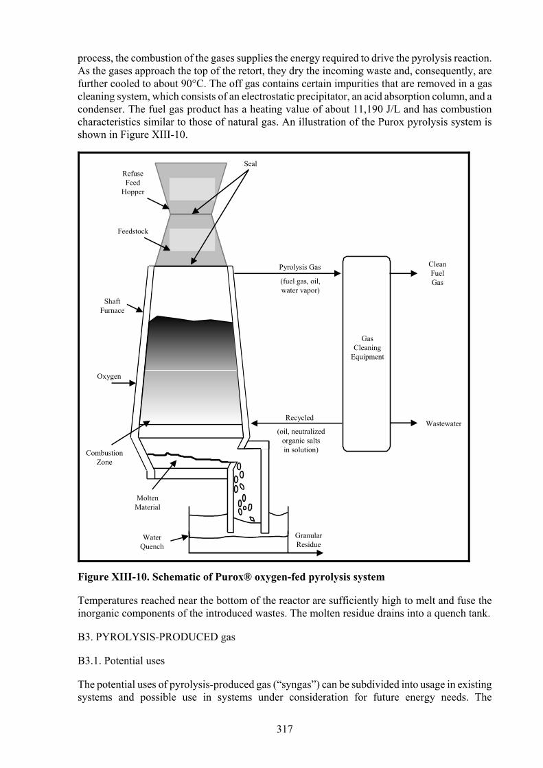
process, the combustion of the gases supplies the energy required to drive the pyrolysis reaction. As the gases approach the top of the retort, they dry the incoming waste and, consequently, are further cooled to about 90°C. The off gas contains certain impurities that are removed in a gas cleaning system, which consists of an electrostatic precipitator, an acid absorption column, and a condenser. The fuel gas product has a heating value of about 11,190 J/L and has combustion characteristics similar to those of natural gas. An illustration of the Purox pyrolysis system is shown in Figure XIII-10.
GasCleaning
Equipment
Wastewater
CleanFuelGas
Pyrolysis Gas
(fuel gas, oil,water vapor)
Recycled
(oil, neutralizedorganic saltsin solution)
GranularResidue
WaterQuench
MoltenMaterial
SealRefuseFeed
Hopper
Feedstock
ShaftFurnace
Oxygen
CombustionZone
Figure XIII-10. Schematic of Purox® oxygen-fed pyrolysis system
Temperatures reached near the bottom of the reactor are sufficiently high to melt and fuse the inorganic components of the introduced wastes. The molten residue drains into a quench tank.
B3. PYROLYSIS-PRODUCED gas
B3.1. Potential uses
The potential uses of pyrolysis-produced gas (“syngas”) can be subdivided into usage in existing systems and possible use in systems under consideration for future energy needs. The
317

consideration of these two potentials has a significant bearing on the required composition, heating value, and purity of the gas.
Pyrolysis gas could be used by utilities and by large industrial energy users if the heating value and composition of the gas are compatible with existing combustion equipment. Ideally, compatibility would require that the gas have a heating value as close as possible to 37,000 J/L and have low concentrations of carbon monoxide (CO), hydrogen sulphide (H2S), and hydrogen (H2). Burning fuel gas that has a low heating value and high concentrations of CO, H2S, and H2 can lead to the development of a number of problems requiring equipment modifications and alternate distribution arrangements.
B3.2. Composition and heating value
In this section is discussed the compatibility and, hence, marketability of syngas with existing natural gas-fired burners. At the same time, other factors concerning gas composition, such as CO, H2S, and N2 content, have a bearing on the marketing aspects of a syngas. It should be noted that all questions of marketability in this discussion deal with technical considerations. Questions concerning the safe transmission and use of a syngas that contains a large amount of CO add a socio-political feature to the overall acceptance of syngas use.
From the standpoint of maximum heating value, syngas should contain as few non-combustible constituents as possible. Non-combustible components of typical syngas are N2, O2, and CO2. The presence of these components dilutes the heating value of the gas and, consequently, reduces its marketability, other factors remaining equal. As shown by the data in Table XIII-2, systems that involve the use of air (i.e., of a combustion step) in the generation of energy to sustain the pyrolysis reaction (Andco-Torrax and Monsanto systems) produce a gas that contains a large percentage of N2. (The gas from the Andco-Torrax system is 55% N; and that from the Monsanto, 69.3%.) Consequently, the heating values of these two syngases are low -- namely, 5,716 and 3,688 J/L, respectively.
Table XIII-2. Syngas composition from pyrolytic conversion of solid wastes
Gas Composition of Major Constituents (% dry basis)
System
H2 CO CO2 CH4 C2H2 C2H4 C2H6 C6H6 N2 O2
Organic Vapour
s
% of
Total a
Average Heating Value (J/L)
Andco-Torrax 15.0 14.0 10.0 3.0 NRb NR 1.0 NR 55.0 2 NAc 100.0 5,716
Monsanto Landgard
6.6 6.6 11.4 2.8 NR 1.7 NR NR 69.3 1.6 NA 100.0 3,688
Union Carbide Purox
24.0 40.0 25.0 5.6 0.7 2.1 0.3 0.3 0 0 0.15 98.15d 11,370
a Percent of major constituents in total syngas composition. b NR = non-reported. c NA = not available. d C3H6 (0.3), C3H8 (0.2), C4 (0.5), C5 (0.4), C7H8 (0.1), C6+ (0.2), H2S (0.05), and CH3OH
(0.1) are the remaining 1.85 of the Purox pyrolysis gas.
On the other hand, the fuel gas produced by the Union Carbide (Purox) process has a heating value of 11,370 J/L. Air is not introduced into the pyrolytic reactor vessel in the Purox system. Consequently, the heating value of its gas product is substantially higher than that of the others.
From an operational point of view, the use of gaseous fuels having a heating value less than 7,460 J/L is attended by technical problems. The problems result from using a burner, or boiler, or both,
318

designed and optimised specifically to burn 39,000 J/L natural gas, 44,200 J/L fuel oil, or 28,000 J/g coal and trying to substitute a gaseous fuel of lower heating value. If syngas of less than 7,460 J/L is substituted into an existing fossil fuel system, the overall operation of the burner/boiler heat recovery system is reduced to undesirable levels [8,9]. The use of low heat-value syngas would have to be limited to burners and boilers specifically designed to burn it. Systems providing less than 7,460 J/L gas would involve a capital investment lower than that required for producing gases that have heating values in the 10,000 to 19,000 J/L range. The capital cost for the latter is higher by reason of the additional equipment or processes involved in providing pure oxygen for the pyrolysis reaction (e.g., Union Carbide system).
B3.3. Process yield
The net yield (kJ/Mg of solid waste) determines the plant size required for meeting a given energy demand. Here, net yield is taken as the useful energy net output from the pyrolysis plant (i.e., after the extraction of energy for in-plant use and for process losses) divided by the quantity of solid waste received at the plant gate. The net yields expressed in MkJ/Mg of solid waste for the three pyrolysis systems discussed here are estimated as follows: Andco-Torrax 9.63; Monsanto, 9.24; and Union Carbide, 7.56. The system with the highest net yield will produce the greatest amount of useful energy from a given quantity of solid waste. The average yield of the three systems is 8.47 MkJ/Mg of waste.
B3.4. Upgrading syngas quality
Upgrading syngas involves one of two approaches: The first approach is to convert the syngas to pipeline quality gas, i.e., approximately 33,600 J/L. A number of different conversion processes are available through which a syngas can be converted to pipeline quality. The second approach is to increase the gas heating value, but not to pipeline quality. The second alternative results in a gas that has heating values in the range of 5,600 to 21,300 J/L. The relative merits of either approach depend upon certain technical and economic considerations. The added cost for syngas improvement must be weighed against the additional revenue gained by improving the gas quality. Since improved syngas quality will usually increase the marketability of the product, the degree of cleanup is germane to economic feasibility.
From an operating and safety standpoint, converting syngas to pipeline quality gas, i.e., synthetic natural gas (SNG), is preferable since to do so would result in minimising the CO and H2S problems. The objective would be to produce a synthetic natural gas (34,500 J/L) from solid waste that could be injected into the natural gas network of a utility. In certain areas, however, the operation and interconnections of the transmission and distribution systems may be so complex that the injection of SNG would result in a reduction in heating value in excess of allowable variations.
Another approach to syngas quality improvement could involve the removal of CO2, N2, and even of H2 should cleanup prove to be technologically and economically feasible. CO2 and N2 may be removed to improve the overall heating value of the syngas. On the other hand, H2 may be removed to improve burner performance or to produce H2 gas for sale.
C. Precautions
Some important lessons have been learned with regard to thermal conversion systems in general that combust processed or unprocessed municipal solid waste. These lessons and their ramifications should be considered when designing, evaluating, or implementing solid waste-fired thermal conversion processes. Experience has shown the following, listed in no particular order of priority.
319

• If air pollutant emissions must be controlled to very low levels, such as those established in Europe, Japan, and the United States, then process control must be exercised from the point of fuel delivery to the points of discharge of ash, wastewater, and combustion gases. The upshot is that costly and complex pollution control systems will be required and the system will have to be operated and maintained continuously.
• Inattention to the characteristics, quantities, and material handling of ash will probably result in low availability of the ash handling system. The design of ash handling systems must include an analysis of the fuel characteristics, of the effect of the combustion process on ash formation, and of the proper types of equipment for ash treatment and handling.
• The composition and quantities of the waste must be adequately estimated over the lifetime of the thermal conversion project. If recycling of materials is planned, the design of the thermal system must take the changes in composition and availability of the fuel into account.
• Material handling of unprocessed MSW and of prepared fuels (i.e., RDF) is an area that has proven to be highly susceptible to oversights during design and operation. Instances that require special attention include replacement, conversion, or adaptation of existing coal-fired material handling systems to accommodate RDF if co-firing of coal and RDF is planned for an existing coal-fired combustion system. Such modifications obviously must be accounted for in the determination of the overall cost of the energy production system.
D. References
1. Goodrich, W.F., The Economic Disposal of Towns Refuse, P.S. King and Son, London, England, 1901.
2. Weinstein, N.J., “Municipal-Scale Thermal Processing of Solid Wastes”, EPA/530/SW-1330, prepared for U.S. Environmental Protection Agency, 1977.
3. Shuster, W.W., Partial Oxidation of Solid Organic Wastes, Final Report, Bureau of Solid Waste Management SW-7RG, 1970.
4. Groner, R.R., et al., “The Chemical Transformation of Solid Wastes”, AICHE Symposium Series 68(122):28-39, 1972.
5. Davidson, P.E. and T.W. Lucas, “The Andco-Torrax High-Temperature Slagging Pyrolysis System”, Solid Wastes and Residues - Conversion by Advanced Thermal Processes, ACS Symposium Series 76, 1978.
6. Mark, S.D., D. Bohn, and C. Melan, “Recent Developments in a Slagging Process for Conversion of Refuse to Energy”, Proceedings from the International Recycling Congress, Berlin, West Germany, 1979.
7. Levy, S.J., “Pyrolysis of Municipal Solid Waste”, Waste Age, 5(4):14-20, October 1974.
8. Murray, R.H., “Low Btu Gas for Industrial Fuels Market”, presented at Symposium on Commercialization of Synthetic Fuels, American Chemical Society, Colorado Springs, Colorado, USA, February 1976.
9. Frendberg, A.M., “Performance Characteristics of Existing Utility Boilers When Fired with Low Btu Gas”, EPRI Symposium, “Power Generation Clean Fuels Today”, Monterey, California, USA, April 1974.
320

10. Savage, G.M., D.L. Bordson, and L.F. Diaz, “Important Issues Related to Air Pollution at Municipal Solid Waste Facilities”, presented at 25th Annual Governmental Refuse Collection and Disposal Association (GRCDA) Conference in St. Paul, Minnesota, USA, August 1987, Environmental Progress, 7(2):123-130, May 1988.
11. Bonk, D.L., H.M. McDaniel, M.R. De Lallo, Jr., and R. Zaharchuk, “Performance Analysis of Co-Firing Waste Materials in an Advanced Pressurized Fluidized-Bed Combustor”, Solid Waste Management: Thermal Treatment & Waste-to-Energy Technologies, VIP-53, proceedings of International Technologies Conference, Washington, DC, USA, April 1995, Air & Waste Management Association, 1996.
12. Murphy, M.L., “Using Fluidized Bed Boilers for Burning Refuse-Derived Fuel”, Solid Waste Technologies, VIII(5):34, September/October 1994.
13. Chang, Y., J. Kang, and C. Ho, “Circulating Fluidized Bed Incineration of Industrial Solid Wastes”, Waste Management & Research, 10:357-369, 1992.
14. Niessen, Walter R., Combustion and Incineration Processes, Third Edition, Marcel Dekker, New York, New York, 2002.
321
