european copper institute
TRANSCRIPT
European Copper Institute
APPLICATION NOTE HARMONICS: CAUSES AND EFFECTS
David Chapman
November 2011
ECI Publication No Cu0119
Available from www.leonardo-energy.org /node/1283
Publication No Cu0119
Issue Date: November 2011
Page i
Document Issue Control Sheet
Document Title: Application Note – Harmonics: Causes and Effects
Publication No: Cu0119
Issue: 02
Release: November 2011
Author(s): David Chapman
Reviewer(s): /
Document History
Issue Date Purpose
1 March
2001
Initial publication
2 November
2011
Reworked by the author for adoption into the Good Practice Guide
3
Disclaimer
While this publication has been prepared with care, European Copper Institute and other contributors provide
no warranty with regards to the content and shall not be liable for any direct, incidental or consequential
damages that may result from the use of the information or the data contained.
Copyright© European Copper Institute.
Reproduction is authorised providing the material is unabridged and the source is acknowledged.
Publication No Cu0119
Issue Date: November 2011
Page ii
CONTENTS
Summary ........................................................................................................................................................ 1
Causes and Effects .......................................................................................................................................... 2
Introduction ............................................................................................................................................................ 2
What are Harmonics? ............................................................................................................................................. 2
Types of equipment that generate harmonics ....................................................................................................... 3
Single phase loads .................................................................................................................................... 3
Three phase loads .................................................................................................................................... 5
Theoretical background – how harmonics are generated ....................................................................... 7
Problems caused by harmonics .............................................................................................................................. 9
Harmonic problems within the installation .............................................................................................. 9
Harmonic problems affecting the supply ............................................................................................... 14
Harmonic mitigation measures ............................................................................................................................ 15
Passive Shunt Filters ............................................................................................................................... 15
Passive Series Filters ............................................................................................................................... 16
Isolation Transformers ........................................................................................................................... 16
Active Harmonic Conditioners ................................................................................................................ 17
Conclusion .................................................................................................................................................... 18
Publication No Cu0119
Issue Date: November 2011
Page 1
SUMMARY Today, nearly every piece of electrical equipment generates harmonic currents and voltages. This Application
Note gives a comprehensive and up-to-date overview of the subject. It explains why harmonic problems have
been increasing over recent years, how they are generated, and by which type of equipment. It presents an
overview of the various problems harmonic currents can create. Most of them are either related to different
kinds of overloading – leading to problems of efficiency loss and overheating – or to disturbances of control
and safety devices.
This Application Note also presents a brief overview of the available solutions. The four main mitigation
solutions are passive shunt filters, passive series filters, isolation transformers, and active harmonic
conditioners. The Application Note concludes that good design practice, the right electrical equipment, and
good maintenance are the keys to preventing future problems.
Publication No Cu0119
Issue Date: November 2011
Page 2
CAUSES AND EFFECTS
INTRODUCTION
Harmonic currents and voltages cause many problems in electrical installations, including overheating of
equipment and cabling, reduced energy efficiency, and reduced functionality due to loss of electromagnetic
compatibility. Harmonic currents from installations flow back into the network and propagate as voltage
harmonics, distorting the supply waveform, increasing network losses, and reducing the reliability of
equipment.
Harmonic currents have been present in the electricity supply system for many years. Initially they were
produced only by the mercury arc rectifiers used to convert AC to DC current for railway electrification and
industrial DC variable speed drives, and by direct half-wave rectification used in radio and television sets. More
recently, the range of types and the number of units of equipment causing harmonics have risen sharply, and
will continue to rise. Designers and specifiers must now consider harmonics and their side effects very
carefully to ensure the safety and resilience of installations and to meet harmonic emission limits.
WHAT ARE HARMONICS?
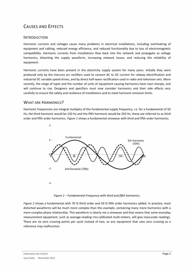
Harmonic frequencies are integral multiples of the fundamental supply frequency, i.e. for a fundamental of 50
Hz, the third harmonic would be 150 Hz and the fifth harmonic would be 250 Hz; these are referred to as third
order and fifth order harmonics. Figure 1 shows a fundamental sinewave with third and fifth order harmonics.
Figure 1 – Fundamental Frequency with third and fifth harmonics.
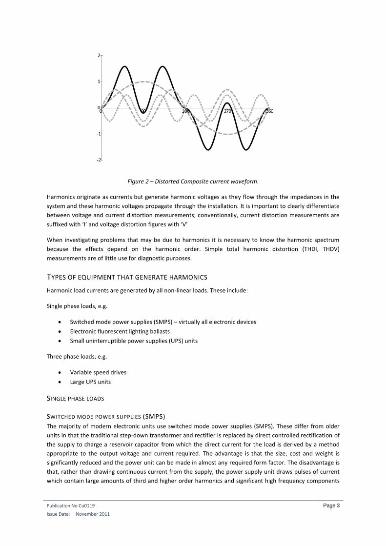
Figure 2 shows a fundamental with 70 % third order and 50 % fifth order harmonics added. In practice, most
distorted waveforms will be much more complex than this example, containing many more harmonics with a
more complex phase relationship. This waveform is clearly not a sinewave and that means that some everyday
measurement equipment, such as average-reading rms-calibrated multi-meters, will give inaccurate readings.
There are six zero crossing points per cycle instead of two, so any equipment that uses zero crossing as a
reference may malfunction.
Publication No Cu0119
Issue Date: November 2011
Page 3
Figure 2 – Distorted Composite current waveform.
Harmonics originate as currents but generate harmonic voltages as they flow through the impedances in the
system and these harmonic voltages propagate through the installation. It is important to clearly differentiate
between voltage and current distortion measurements; conventionally, current distortion measurements are
suffixed with ‘I’ and voltage distortion figures with ‘V’
When investigating problems that may be due to harmonics it is necessary to know the harmonic spectrum
because the effects depend on the harmonic order. Simple total harmonic distortion (THDI, THDV)
measurements are of little use for diagnostic purposes.
TYPES OF EQUIPMENT THAT GENERATE HARMONICS
Harmonic load currents are generated by all non-linear loads. These include:
Single phase loads, e.g.
Switched mode power supplies (SMPS) – virtually all electronic devices
Electronic fluorescent lighting ballasts
Small uninterruptible power supplies (UPS) units
Three phase loads, e.g.
Variable speed drives
Large UPS units
SINGLE PHASE LOADS
SWITCHED MODE POWER SUPPLIES (SMPS)
The majority of modern electronic units use switched mode power supplies (SMPS). These differ from older
units in that the traditional step-down transformer and rectifier is replaced by direct controlled rectification of
the supply to charge a reservoir capacitor from which the direct current for the load is derived by a method
appropriate to the output voltage and current required. The advantage is that the size, cost and weight is
significantly reduced and the power unit can be made in almost any required form factor. The disadvantage is
that, rather than drawing continuous current from the supply, the power supply unit draws pulses of current
which contain large amounts of third and higher order harmonics and significant high frequency components
Publication No Cu0119
Issue Date: November 2011
Page 4
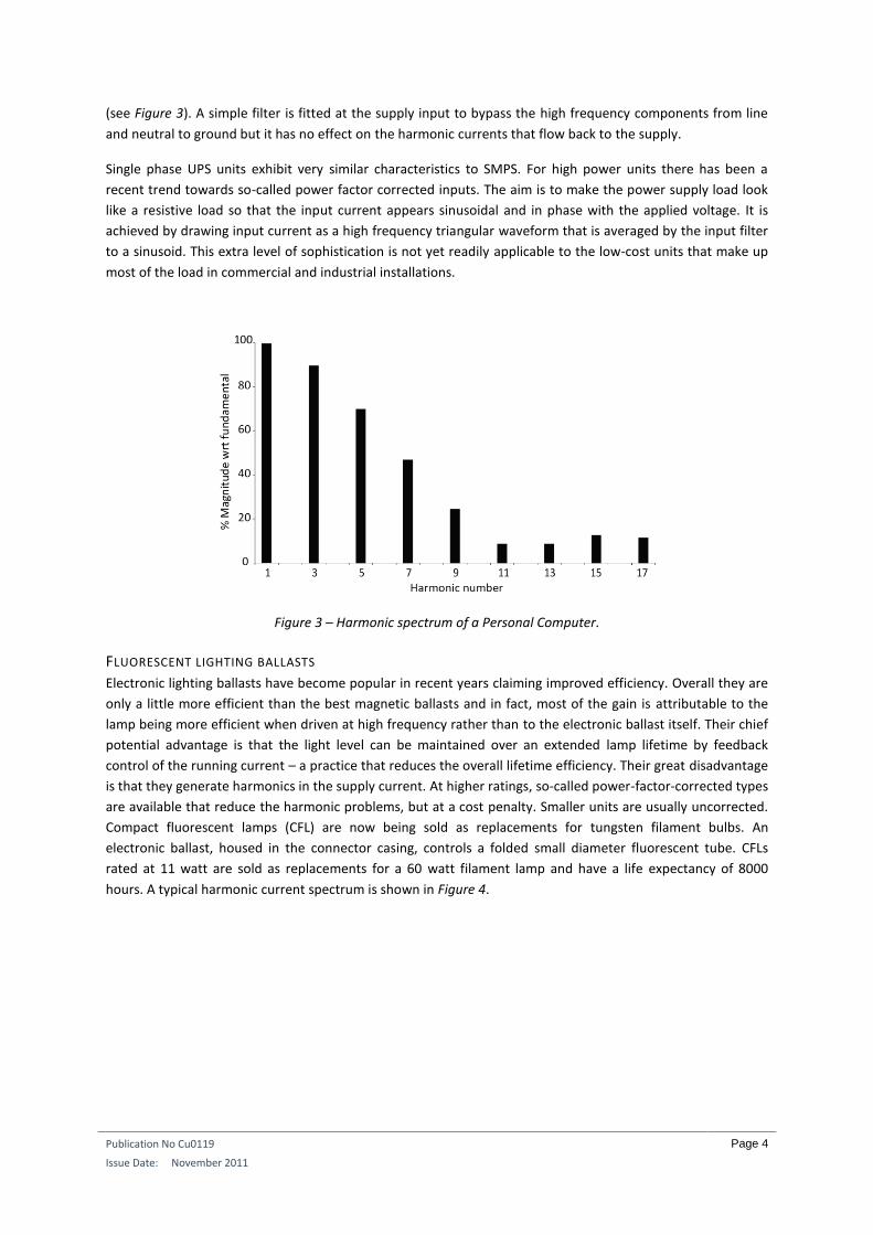
(see Figure 3). A simple filter is fitted at the supply input to bypass the high frequency components from line
and neutral to ground but it has no effect on the harmonic currents that flow back to the supply.
Single phase UPS units exhibit very similar characteristics to SMPS. For high power units there has been a
recent trend towards so-called power factor corrected inputs. The aim is to make the power supply load look
like a resistive load so that the input current appears sinusoidal and in phase with the applied voltage. It is
achieved by drawing input current as a high frequency triangular waveform that is averaged by the input filter
to a sinusoid. This extra level of sophistication is not yet readily applicable to the low-cost units that make up
most of the load in commercial and industrial installations.
Figure 3 – Harmonic spectrum of a Personal Computer.
FLUORESCENT LIGHTING BALLASTS
Electronic lighting ballasts have become popular in recent years claiming improved efficiency. Overall they are
only a little more efficient than the best magnetic ballasts and in fact, most of the gain is attributable to the
lamp being more efficient when driven at high frequency rather than to the electronic ballast itself. Their chief
potential advantage is that the light level can be maintained over an extended lamp lifetime by feedback
control of the running current – a practice that reduces the overall lifetime efficiency. Their great disadvantage
is that they generate harmonics in the supply current. At higher ratings, so-called power-factor-corrected types
are available that reduce the harmonic problems, but at a cost penalty. Smaller units are usually uncorrected.
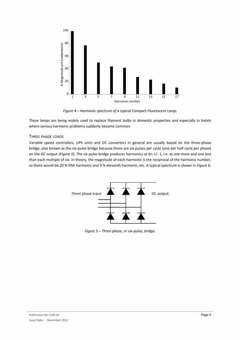
Compact fluorescent lamps (CFL) are now being sold as replacements for tungsten filament bulbs. An
electronic ballast, housed in the connector casing, controls a folded small diameter fluorescent tube. CFLs
rated at 11 watt are sold as replacements for a 60 watt filament lamp and have a life expectancy of 8000
hours. A typical harmonic current spectrum is shown in Figure 4.
Publication No Cu0119
Issue Date: November 2011
Page 5
Figure 4 – Harmonic spectrum of a typical Compact Fluorescent Lamp.
These lamps are being widely used to replace filament bulbs in domestic properties and especially in hotels
where serious harmonic problems suddenly became common.
THREE PHASE LOADS Variable speed controllers, UPS units and DC converters in general are usually based on the three-phase
bridge, also known as the six-pulse bridge because there are six pulses per cycle (one per half cycle per phase)
on the DC output (Figure 5). The six pulse bridge produces harmonics at 6n +/- 1, i.e. at one more and one less
than each multiple of six. In theory, the magnitude of each harmonic is the reciprocal of the harmonic number,
so there would be 20 % fifth harmonic and 9 % eleventh harmonic, etc. A typical spectrum is shown in Figure 6.
Figure 5 – Three-phase, or six-pulse, bridge.
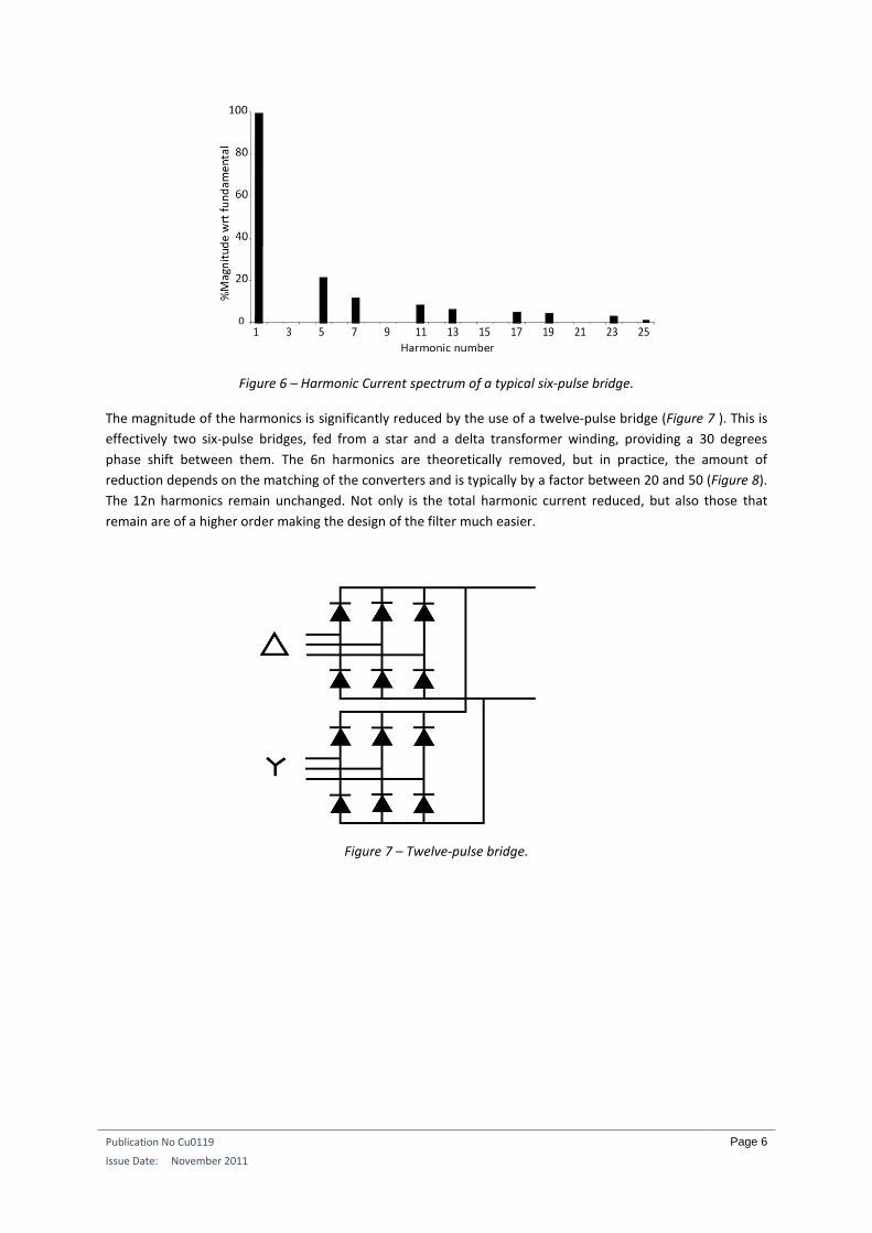
Publication No Cu0119
Issue Date: November 2011
Page 6
Figure 6 – Harmonic Current spectrum of a typical six-pulse bridge.
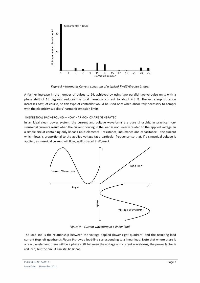
The magnitude of the harmonics is significantly reduced by the use of a twelve-pulse bridge (Figure 7 ). This is
effectively two six-pulse bridges, fed from a star and a delta transformer winding, providing a 30 degrees
phase shift between them. The 6n harmonics are theoretically removed, but in practice, the amount of
reduction depends on the matching of the converters and is typically by a factor between 20 and 50 (Figure 8).
The 12n harmonics remain unchanged. Not only is the total harmonic current reduced, but also those that
remain are of a higher order making the design of the filter much easier.
Figure 7 – Twelve-pulse bridge.
Publication No Cu0119
Issue Date: November 2011
Page 7
Figure 8 – Harmonic Current spectrum of a typical TWELVE-pulse bridge.
A further increase in the number of pulses to 24, achieved by using two parallel twelve-pulse units with a
phase shift of 15 degrees, reduces the total harmonic current to about 4.5 %. The extra sophistication
increases cost, of course, so this type of controller would be used only when absolutely necessary to comply
with the electricity suppliers’ harmonic emission limits.
THEORETICAL BACKGROUND – HOW HARMONICS ARE GENERATED In an ideal clean power system, the current and voltage waveforms are pure sinusoids. In practice, non-
sinusoidal currents result when the current flowing in the load is not linearly related to the applied voltage. In
a simple circuit containing only linear circuit elements – resistance, inductance and capacitance – the current
which flows is proportional to the applied voltage (at a particular frequency) so that, if a sinusoidal voltage is
applied, a sinusoidal current will flow, as illustrated in Figure 9.
Figure 9 – Current waveform in a linear load.
The load-line is the relationship between the voltage applied (lower right quadrant) and the resulting load
current (top left quadrant); Figure 9 shows a load-line corresponding to a linear load. Note that where there is
a reactive element there will be a phase shift between the voltage and current waveforms; the power factor is
reduced, but the circuit can still be linear.
Publication No Cu0119
Issue Date: November 2011
Page 8
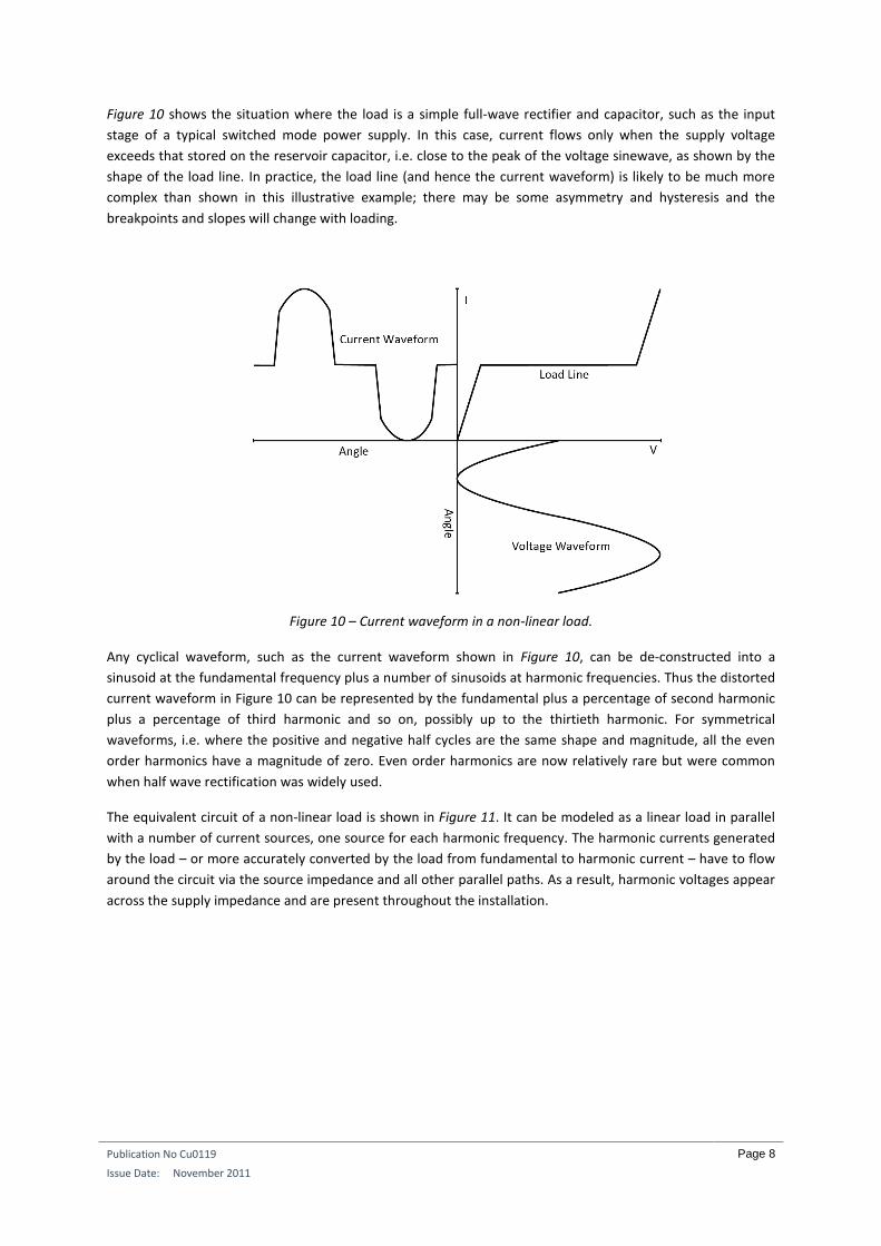
Figure 10 shows the situation where the load is a simple full-wave rectifier and capacitor, such as the input
stage of a typical switched mode power supply. In this case, current flows only when the supply voltage
exceeds that stored on the reservoir capacitor, i.e. close to the peak of the voltage sinewave, as shown by the
shape of the load line. In practice, the load line (and hence the current waveform) is likely to be much more
complex than shown in this illustrative example; there may be some asymmetry and hysteresis and the
breakpoints and slopes will change with loading.
Figure 10 – Current waveform in a non-linear load.
Any cyclical waveform, such as the current waveform shown in Figure 10, can be de-constructed into a
sinusoid at the fundamental frequency plus a number of sinusoids at harmonic frequencies. Thus the distorted
current waveform in Figure 10 can be represented by the fundamental plus a percentage of second harmonic
plus a percentage of third harmonic and so on, possibly up to the thirtieth harmonic. For symmetrical
waveforms, i.e. where the positive and negative half cycles are the same shape and magnitude, all the even
order harmonics have a magnitude of zero. Even order harmonics are now relatively rare but were common
when half wave rectification was widely used.
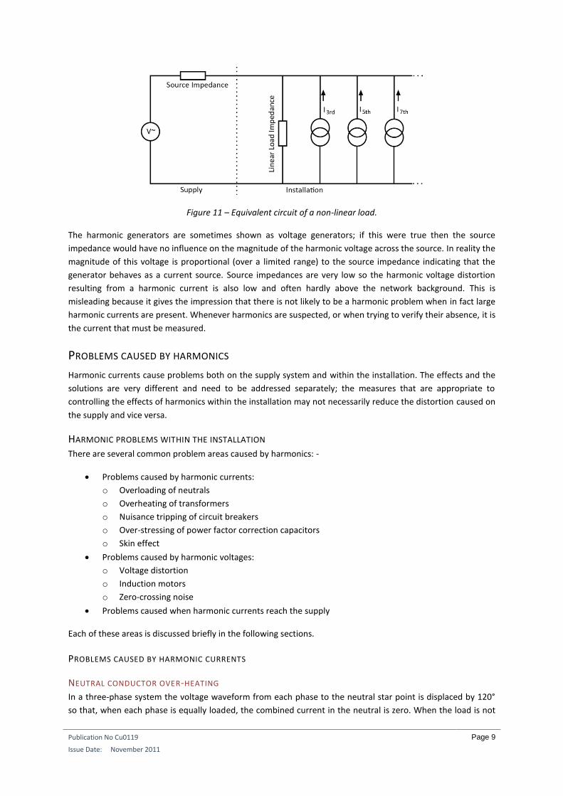
The equivalent circuit of a non-linear load is shown in Figure 11. It can be modeled as a linear load in parallel
with a number of current sources, one source for each harmonic frequency. The harmonic currents generated
by the load – or more accurately converted by the load from fundamental to harmonic current – have to flow
around the circuit via the source impedance and all other parallel paths. As a result, harmonic voltages appear
across the supply impedance and are present throughout the installation.
Publication No Cu0119
Issue Date: November 2011
Page 9
Figure 11 – Equivalent circuit of a non-linear load.
The harmonic generators are sometimes shown as voltage generators; if this were true then the source
impedance would have no influence on the magnitude of the harmonic voltage across the source. In reality the
magnitude of this voltage is proportional (over a limited range) to the source impedance indicating that the
generator behaves as a current source. Source impedances are very low so the harmonic voltage distortion
resulting from a harmonic current is also low and often hardly above the network background. This is
misleading because it gives the impression that there is not likely to be a harmonic problem when in fact large
harmonic currents are present. Whenever harmonics are suspected, or when trying to verify their absence, it is
the current that must be measured.
PROBLEMS CAUSED BY HARMONICS
Harmonic currents cause problems both on the supply system and within the installation. The effects and the
solutions are very different and need to be addressed separately; the measures that are appropriate to
controlling the effects of harmonics within the installation may not necessarily reduce the distortion caused on
the supply and vice versa.
HARMONIC PROBLEMS WITHIN THE INSTALLATION There are several common problem areas caused by harmonics: -
Problems caused by harmonic currents:
o Overloading of neutrals
o Overheating of transformers
o Nuisance tripping of circuit breakers
o Over-stressing of power factor correction capacitors
o Skin effect
Problems caused by harmonic voltages:
o Voltage distortion
o Induction motors
o Zero-crossing noise
Problems caused when harmonic currents reach the supply
Each of these areas is discussed briefly in the following sections.
PROBLEMS CAUSED BY HARMONIC CURRENTS
NEUTRAL CONDUCTOR OVER-HEATING
In a three-phase system the voltage waveform from each phase to the neutral star point is displaced by 120°
so that, when each phase is equally loaded, the combined current in the neutral is zero. When the load is not
Publication No Cu0119
Issue Date: November 2011
Page 10
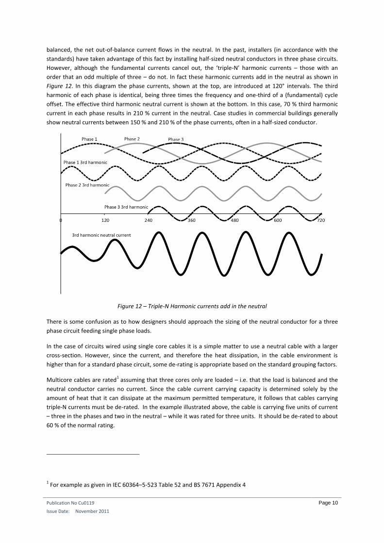
balanced, the net out-of-balance current flows in the neutral. In the past, installers (in accordance with the
standards) have taken advantage of this fact by installing half-sized neutral conductors in three phase circuits.
However, although the fundamental currents cancel out, the ‘triple-N’ harmonic currents – those with an
order that an odd multiple of three – do not. In fact these harmonic currents add in the neutral as shown in
Figure 12. In this diagram the phase currents, shown at the top, are introduced at 120° intervals. The third
harmonic of each phase is identical, being three times the frequency and one-third of a (fundamental) cycle
offset. The effective third harmonic neutral current is shown at the bottom. In this case, 70 % third harmonic
current in each phase results in 210 % current in the neutral. Case studies in commercial buildings generally
show neutral currents between 150 % and 210 % of the phase currents, often in a half-sized conductor.
Figure 12 – Triple-N Harmonic currents add in the neutral
There is some confusion as to how designers should approach the sizing of the neutral conductor for a three
phase circuit feeding single phase loads.
In the case of circuits wired using single core cables it is a simple matter to use a neutral cable with a larger
cross-section. However, since the current, and therefore the heat dissipation, in the cable environment is
higher than for a standard phase circuit, some de-rating is appropriate based on the standard grouping factors.
Multicore cables are rated1 assuming that three cores only are loaded – i.e. that the load is balanced and the
neutral conductor carries no current. Since the cable current carrying capacity is determined solely by the
amount of heat that it can dissipate at the maximum permitted temperature, it follows that cables carrying
triple-N currents must be de-rated. In the example illustrated above, the cable is carrying five units of current
– three in the phases and two in the neutral – while it was rated for three units. It should be de-rated to about
60 % of the normal rating.
1 For example as given in IEC 60364–5-523 Table 52 and BS 7671 Appendix 4
Publication No Cu0119
Issue Date: November 2011
Page 11
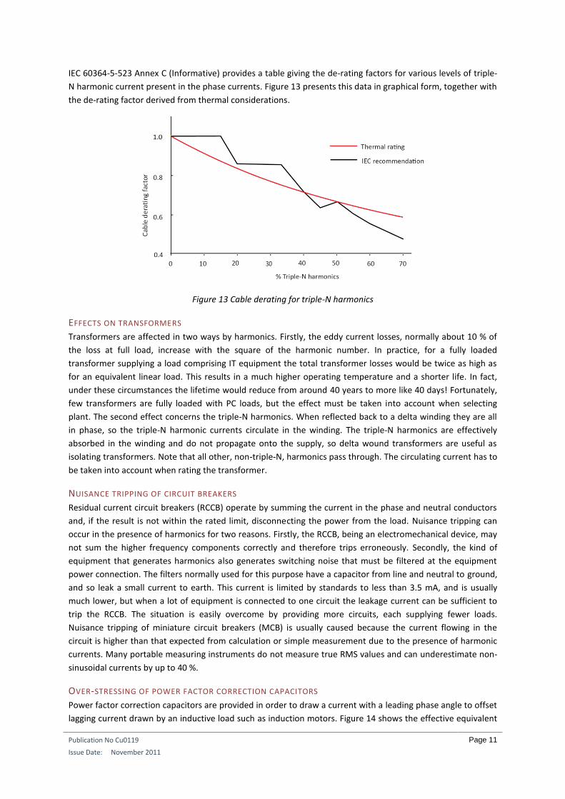
IEC 60364-5-523 Annex C (Informative) provides a table giving the de-rating factors for various levels of triple-
N harmonic current present in the phase currents. Figure 13 presents this data in graphical form, together with
the de-rating factor derived from thermal considerations.
Figure 13 Cable derating for triple-N harmonics
EFFECTS ON TRANSFORMERS
Transformers are affected in two ways by harmonics. Firstly, the eddy current losses, normally about 10 % of
the loss at full load, increase with the square of the harmonic number. In practice, for a fully loaded
transformer supplying a load comprising IT equipment the total transformer losses would be twice as high as
for an equivalent linear load. This results in a much higher operating temperature and a shorter life. In fact,
under these circumstances the lifetime would reduce from around 40 years to more like 40 days! Fortunately,
few transformers are fully loaded with PC loads, but the effect must be taken into account when selecting
plant. The second effect concerns the triple-N harmonics. When reflected back to a delta winding they are all
in phase, so the triple-N harmonic currents circulate in the winding. The triple-N harmonics are effectively
absorbed in the winding and do not propagate onto the supply, so delta wound transformers are useful as
isolating transformers. Note that all other, non-triple-N, harmonics pass through. The circulating current has to
be taken into account when rating the transformer.
NUISANCE TRIPPING OF CIRCUIT BREAKERS
Residual current circuit breakers (RCCB) operate by summing the current in the phase and neutral conductors
and, if the result is not within the rated limit, disconnecting the power from the load. Nuisance tripping can
occur in the presence of harmonics for two reasons. Firstly, the RCCB, being an electromechanical device, may
not sum the higher frequency components correctly and therefore trips erroneously. Secondly, the kind of
equipment that generates harmonics also generates switching noise that must be filtered at the equipment
power connection. The filters normally used for this purpose have a capacitor from line and neutral to ground,
and so leak a small current to earth. This current is limited by standards to less than 3.5 mA, and is usually
much lower, but when a lot of equipment is connected to one circuit the leakage current can be sufficient to
trip the RCCB. The situation is easily overcome by providing more circuits, each supplying fewer loads.
Nuisance tripping of miniature circuit breakers (MCB) is usually caused because the current flowing in the
circuit is higher than that expected from calculation or simple measurement due to the presence of harmonic
currents. Many portable measuring instruments do not measure true RMS values and can underestimate non-
sinusoidal currents by up to 40 %.
OVER-STRESSING OF POWER FACTOR CORRECTION CAPACITORS
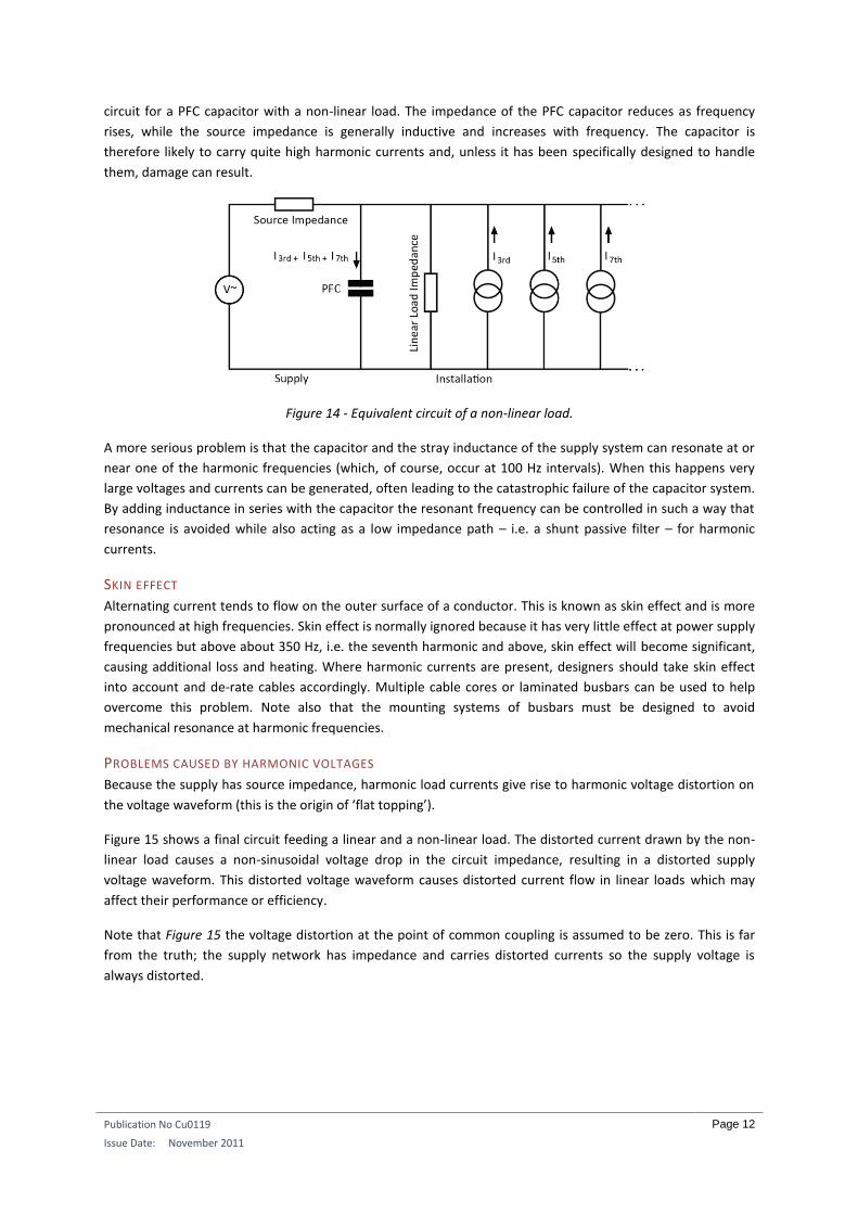
Power factor correction capacitors are provided in order to draw a current with a leading phase angle to offset
lagging current drawn by an inductive load such as induction motors. Figure 14 shows the effective equivalent
Publication No Cu0119
Issue Date: November 2011
Page 12
circuit for a PFC capacitor with a non-linear load. The impedance of the PFC capacitor reduces as frequency
rises, while the source impedance is generally inductive and increases with frequency. The capacitor is
therefore likely to carry quite high harmonic currents and, unless it has been specifically designed to handle
them, damage can result.
Figure 14 - Equivalent circuit of a non-linear load.
A more serious problem is that the capacitor and the stray inductance of the supply system can resonate at or
near one of the harmonic frequencies (which, of course, occur at 100 Hz intervals). When this happens very
large voltages and currents can be generated, often leading to the catastrophic failure of the capacitor system.
By adding inductance in series with the capacitor the resonant frequency can be controlled in such a way that
resonance is avoided while also acting as a low impedance path – i.e. a shunt passive filter – for harmonic
currents.
SKIN EFFECT
Alternating current tends to flow on the outer surface of a conductor. This is known as skin effect and is more
pronounced at high frequencies. Skin effect is normally ignored because it has very little effect at power supply
frequencies but above about 350 Hz, i.e. the seventh harmonic and above, skin effect will become significant,
causing additional loss and heating. Where harmonic currents are present, designers should take skin effect
into account and de-rate cables accordingly. Multiple cable cores or laminated busbars can be used to help
overcome this problem. Note also that the mounting systems of busbars must be designed to avoid
mechanical resonance at harmonic frequencies.
PROBLEMS CAUSED BY HARMONIC VOLTAGES
Because the supply has source impedance, harmonic load currents give rise to harmonic voltage distortion on
the voltage waveform (this is the origin of ‘flat topping’).
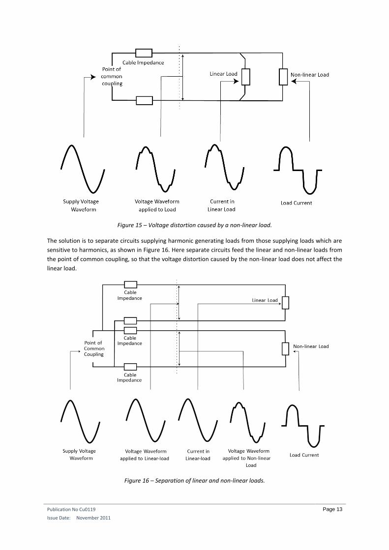
Figure 15 shows a final circuit feeding a linear and a non-linear load. The distorted current drawn by the non-
linear load causes a non-sinusoidal voltage drop in the circuit impedance, resulting in a distorted supply
voltage waveform. This distorted voltage waveform causes distorted current flow in linear loads which may
affect their performance or efficiency.
Note that Figure 15 the voltage distortion at the point of common coupling is assumed to be zero. This is far
from the truth; the supply network has impedance and carries distorted currents so the supply voltage is
always distorted.
Publication No Cu0119
Issue Date: November 2011
Page 13
Figure 15 – Voltage distortion caused by a non-linear load.
The solution is to separate circuits supplying harmonic generating loads from those supplying loads which are
sensitive to harmonics, as shown in Figure 16. Here separate circuits feed the linear and non-linear loads from
the point of common coupling, so that the voltage distortion caused by the non-linear load does not affect the
linear load.
Figure 16 – Separation of linear and non-linear loads.
Publication No Cu0119
Issue Date: November 2011
Page 14
Note that the voltage distortion at the point of common coupling is assumed to be zero in these figures. This is
far from the truth; the supply network has impedance and carries distorted currents so the supply voltage is
always distorted. In reality, the voltage distortion seen in the installation will be the complex sum of the
distortion on the supply and that generated in the installation. The source impedance of the supply network is
very low so distortion levels are also relatively low. However, if the load is transferred to a UPS or standby
generator during a power failure, the source impedance and the resulting voltage distortion in the installation
will be much higher.
Where local transformers are installed, they should be selected to have sufficiently low output impedance and
to have sufficient capacity to withstand the additional heating, in other words, by selecting an appropriately
oversized transformer. Note that it is not appropriate to select a transformer design in which the increase in
capacity is achieved simply by forced cooling – such a unit will run at higher internal temperatures and have a
reduced service life. Forced cooling should be reserved for emergency use only and never relied upon for
normal running.
INDUCTION MOTORS
Harmonic voltage distortion causes increased eddy current losses in motors in the same way as in
transformers. However, additional losses arise due to the generation of harmonic fields in the stator, each of
which is trying to rotate the motor at a different speed either forwards or backwards. High frequency currents
induced in the rotor further increase losses. Where harmonic voltage distortion is present motors should be
de-rated to take account of the additional losses.
ZERO-CROSSING NOISE
Many electronic controllers detect the point at which the supply voltage crosses zero volts to determine when
loads should be turned on. This is done because switching reactive loads at zero voltage does not generate
transients, so reducing electromagnetic interference (EMI) and stress on the semiconductor switching devices.
When harmonics or transients are present on the supply the rate of change of voltage at the crossing becomes
faster and more difficult to identify, leading to erratic operation. There may in fact be several zero-crossings
per half cycle.
HARMONIC PROBLEMS AFFECTING THE SUPPLY When a harmonic current is drawn from the supply it gives rise to a harmonic voltage drop proportional to the
source impedance at the point of common coupling (PCC) and the current. Since the supply network is
generally inductive, the source impedance is higher at higher frequencies. The voltage at the PCC is already
distorted by the harmonic currents drawn by other consumers and by the distortion inherent in transformers,
and each consumer makes an additional contribution.
Clearly, customers cannot be allowed to add pollution to the system to the detriment of other users, so in
most countries the electrical supply industry has established regulations limiting the magnitude of harmonic
current that can be drawn. Many of these codes are based on the UK Electricity Association’s G5/4 (2001), the
first version of which was developed in the 1950s. Limits are placed on that absolute current that can be
drawn for each harmonic order as well as the contribution the site will make to voltage distortion on the
supply.
Meeting the requirements usually requires the application of one or more mitigation measures.
Publication No Cu0119
Issue Date: November 2011
Page 15
HARMONIC MITIGATION MEASURES
Harmonic mitigation measures are required to:
Meet local harmonic emission limits
Reduce overloading of, e.g., cables and transformers
Improve resilience of equipment by reducing voltage waveform distortion
Some mitigation measures have already been mentioned; correct sizing of neutral conductors and
transformers will eliminate the risk of overheating while careful circuit separation will help to minimize voltage
distortion. These are wise and necessary steps to take to protect the installation but they do not help to meet
the local emission limits for which further steps are necessary.
For large infrastructure items, for example, a large variable speed ventilation fan, it could be advantageous to
select a unit with built in harmonic reduction in the form of a filter or an ‘active front end’. Since this particular
load is now electrically nearly linear, it causes no problems in the installation and has no effect on the supply.
This is also a practical approach if the installation sis made up of large numbers of similar items, such as a data
centre, where there is now a wide choice of equipment with low distortion power supplies and carefully
controlled maintenance and purchasing policies are in place. However, generally, it is not practical to rely
solely on equipment selection because purchasing and replacement cannot be sufficiently controlled so other
mitigation measures are needed.
Mitigation methods fall broadly into three groups; passive filters, isolation and harmonic reduction
transformers and active solutions. Each approach has advantages and disadvantages, so there is no single best
solution.
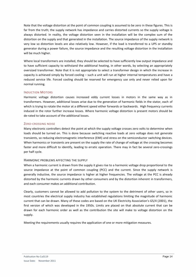
PASSIVE SHUNT FILTERS Passive filters are used to provide a low impedance path for harmonic currents so that they flow in the filter
and not the supply (Figure 17). The filter may be designed for a single harmonic or for a broad band depending
on requirements.
Figure 17 - Passive harmonic shunt filter
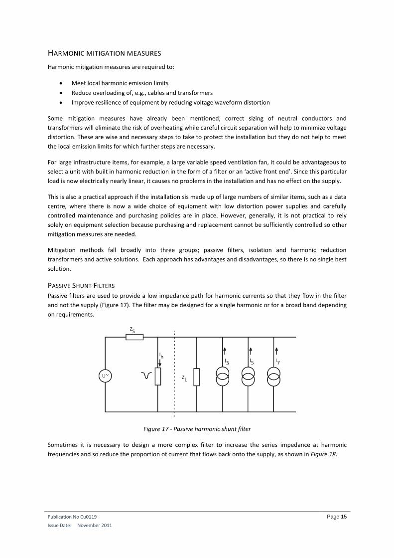
Sometimes it is necessary to design a more complex filter to increase the series impedance at harmonic
frequencies and so reduce the proportion of current that flows back onto the supply, as shown in Figure 18.
Publication No Cu0119
Issue Date: November 2011
Page 16
Figure 18- Passive series and shunt filters
Shunt filters reduce the harmonic current flowing back on to the supply, but do not reduce (and may increase)
the effect of harmonic current in neutrals or the effect on transformers. Usually, shunt filters are designed to
control a few lower order harmonics and are integrated with the power factor correction equipment.
The use of multiple shunt filters in a single installation can be problematic and is usually avoided.
PASSIVE SERIES FILTERS Simple series band stop filters are sometimes proposed, either in the phase or in the neutral. A series filter is
intended to block harmonic currents rather than provide a controlled path for them so there is a large
harmonic voltage drop across it. This harmonic voltage appears across the supply on the load side. Since the
supply voltage is heavily distorted it is no longer within the standards for which equipment was designed and
warranted. Some items of equipment are relatively insensitive to this distortion, but others are very sensitive.
Series filters can be useful in certain circumstances, but should be carefully applied; they cannot be
recommended as a general purpose solution.
ISOLATION TRANSFORMERS As mentioned previously, triple-N currents circulate in the delta windings of transformers. Although this is a
problem for transformer manufacturers and specifiers - the extra load has to be taken into account – it is
beneficial to systems designers because it isolates triple-N harmonics from the supply.
Figure 19 - Delta star isolation transformer
The same effect can be obtained by using a ‘zig-zag’ wound transformer. Zig-zag transformers are star
configuration auto transformers with a particular phase relationship between the windings that are connected
in shunt with the supply.
Delta and zig-zag transformers reduce only triple-N harmonics.
Publication No Cu0119
Issue Date: November 2011
Page 17
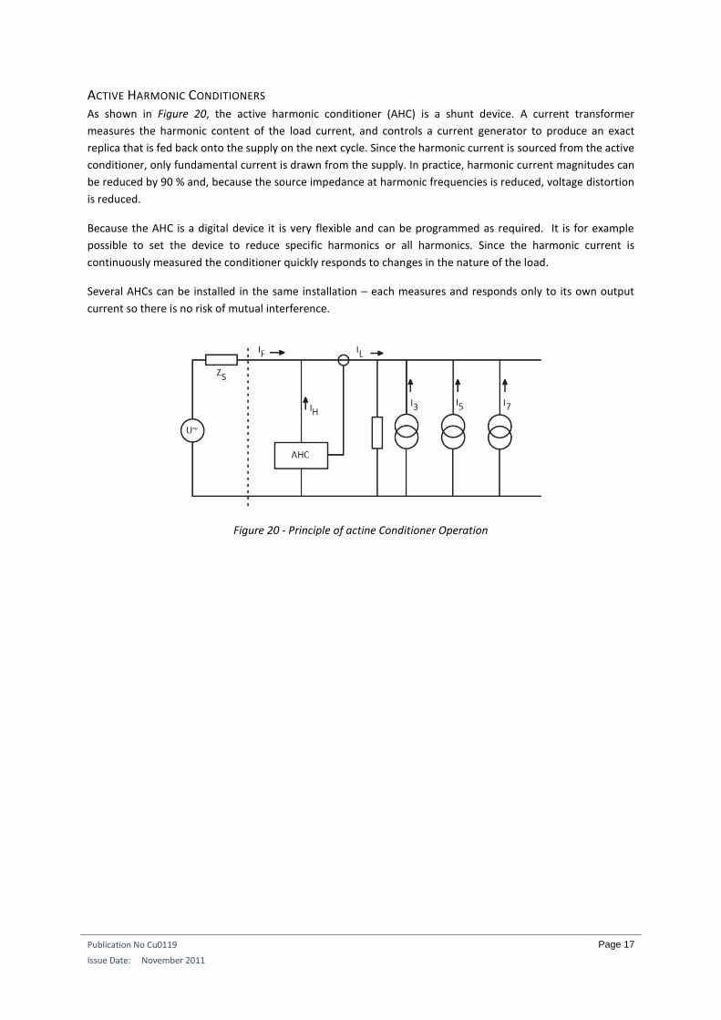
ACTIVE HARMONIC CONDITIONERS As shown in Figure 20, the active harmonic conditioner (AHC) is a shunt device. A current transformer
measures the harmonic content of the load current, and controls a current generator to produce an exact
replica that is fed back onto the supply on the next cycle. Since the harmonic current is sourced from the active
conditioner, only fundamental current is drawn from the supply. In practice, harmonic current magnitudes can
be reduced by 90 % and, because the source impedance at harmonic frequencies is reduced, voltage distortion
is reduced.
Because the AHC is a digital device it is very flexible and can be programmed as required. It is for example
possible to set the device to reduce specific harmonics or all harmonics. Since the harmonic current is
continuously measured the conditioner quickly responds to changes in the nature of the load.
Several AHCs can be installed in the same installation – each measures and responds only to its own output
current so there is no risk of mutual interference.
Figure 20 - Principle of actine Conditioner Operation
Publication No Cu0119
Issue Date: November 2011
Page 18
CONCLUSION Virtually all modern electrical and electronic equipment involves some form of power control and so is a non-
linear load. Linear loads are comparatively rare – undimmed filament bulbs and uncontrolled heaters being the
only common examples.
A range of design strategies and mitigation techniques are available to mitigate the effects of harmonics in
installations and to comply with any harmonic pollution regulations. Each successful strategy to prevent future
problems will be a combination of good design practice, the right electrical equipment, and good maintenance.