ethernet/ip configuration robot as adapter supplement · iv 181389-1cd 181389-1cd ethernet/ip...
TRANSCRIPT
Part Number: 181389-1CDRevision: 0
ETHERNET/IP CONFIGURATIONROBOT AS ADAPTERSUPPLEMENTFOR CONTROLLOGIX/COMPACTLOGIC PLC, YRC1000
Upon receipt of the product and prior to initial operation, read these instructions thoroughly, and retain for future reference.
MOTOMAN INSTRUCTIONS
YRC1000 READ FIRST SAFETY REQUIREMENTS AND INSTRUCTIONSYRC1000 OPERATOR’S MANUAL (for each purpose)YRC1000 MAINTENANCE MANUAL YRC1000 ETHERNET/IP COMMUNICATION, STD LAN PORT MANUAL
The YRC1000 operator’s manual above corresponds to specific usage. Make sure to use the appropriate manual.
1 of 30
181389-1CD
Ethernet/IP Configuration Robot As Adapter
Copyright © 2017 YASKAWA America, Inc.
Terms of Use and Copyright Notice
All rights reserved. This manual is freely available as a service to YASKAWA customers to assist in the operation of Motoman robots, related equipment and software This manual is copyrighted property of Yaskawa and may not be sold or redistributed in any way. You are welcome to copy this document to your computer or mobile device for easy access but you may not copy the PDF files to another website, blog, cloud storage site or any other means of storing or distributing online content.
Printed in the United States of America
First Printing, 2017
YASKAWA America, Inc.Motoman Robotics Division100 Automation WayMiamisburg, OH 45342Phone: 937-847-6200
www.motoman.com
ii 181389-1CD 2 of 30
181389-1CD
Ethernet/IP Configuration Robot As Adapter
DANGER
• This instruction manual is intended to explain mainly the Ethernet/IP Configuration Robot As Adapter for the application to the actual operation. Be sure to read and understand this instruction manual thoroughly before installing and operating the manipulator.
• General items related to safety are listed in Chapter 1: Safety of the YRC1000 Instructions. To ensure correct and safe operation, carefully read the YRC1000 Instructions before reading this manual.
CAUTION
• The photos in this manual are representative examples and differences may exist between them and the delivered product.
• YASKAWA may modify this model without notice when necessary due to product improvements, modifications, or changes in specifications.
• If such modification is made, the manual number will also be revised.
• If your copy of the supplement is damaged or lost, contact a YASKAWA representative to order a new copy. The representatives are listed on the back cover. Be sure to tell the representative the part number listed on the front cover.
• YASKAWA is not responsible for incidents arising from unauthorized modification of its products. Unauthorized modification voids your product's warranty.
DANGER
• Maintenance and inspection must be performed by specified personnel.
Failure to observe this caution may result in electric shock or injury.
• For disassembly or repair, contact your YASKAWA representative.
• Do not remove the motor, and do not release the brake.
Failure to observe these safety precautions may result in death or serious injury from unexpected turning of the manipulator's arm.
iii 181389-1CD 3 of 30
181389-1CD
Definition of Terms Used Often in This SupplementEthernet/IP Configuration Robot As Adapter
Definition of Terms Used Often in This SupplementThe MOTOMAN is the YASKAWA industrial robot product.
The MOTOMAN usually consists of the manipulator, the controller, the programming pendant, and supply cables.
In this supplement, the equipment is designated as follows:
Descriptions of the programming pendant keys, buttons, and displays are shown as follows:
Equipment Manual Designation
YRC1000 controller YRC1000
YRC1000 programming pendant Programming pendant
Cable between the manipulator and the controller
Manipulator cable
Equipment Manual Designation
Programming Pendant
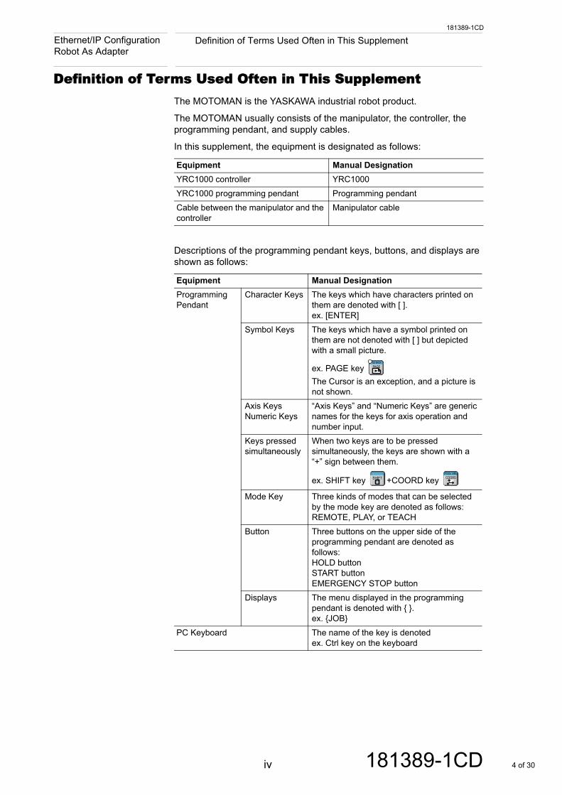
Character Keys The keys which have characters printed on them are denoted with [ ]. ex. [ENTER]
Symbol Keys The keys which have a symbol printed on them are not denoted with [ ] but depicted with a small picture.
ex. PAGE key The Cursor is an exception, and a picture is not shown.
Axis Keys Numeric Keys
“Axis Keys” and “Numeric Keys” are generic names for the keys for axis operation and number input.
Keys pressed simultaneously
When two keys are to be pressed simultaneously, the keys are shown with a “+” sign between them.
ex. SHIFT key +COORD key
Mode Key Three kinds of modes that can be selected by the mode key are denoted as follows:REMOTE, PLAY, or TEACH
Button Three buttons on the upper side of the programming pendant are denoted as follows:HOLD buttonSTART buttonEMERGENCY STOP button
Displays The menu displayed in the programming pendant is denoted with { }.ex. {JOB}
PC Keyboard The name of the key is denotedex. Ctrl key on the keyboard
GO BACK
PAGE
SHIFTTOOL SEL
COORD
iv 181389-1CD 4 of 30
181389-1CD
Registered TrademarkEthernet/IP Configuration Robot As Adapter
Registered TrademarkIn this supplement names of companies, corporations, or products are trademarks, registered trademarks, or bland names for each company or corporation. The indications of ® and TM are omitted.
Customer Support InformationIf assistance is needed with any aspect of this supplement, please contact YASKAWA Customer Support at the following 24-hour telephone number:
YASKAWA Customer Support also has an e-mail address for routine technical inquiries, to contact YASKAWA Customer Support through e-mail use the following address:
When using e-mail to contact YASKAWA Customer Support, please provide a detailed description of the issue, along with complete contact information. Please allow approximately 24 to 36 hours for a response to the inquiry.
DANGER
• Maintenance and inspection must be performed by specified personnel.
Failure to observe this caution may result in electric shock or injury.
• For disassembly or repair, contact your YASKAWA representative.
• Do not remove the motor, and do not release the brake.
Failure to observe these safety precautions may result in death or serious injury from unexpected turning of the manipulator's arm.
NOTICE
Use e-mail for routine inquiries only. If there is an urgent or emergency need for service, replacement parts, or information, contact YASKAWA Customer Support at the telephone number shown above.
(937) 847-3200
v 181389-1CD 5 of 30
vi
181389-1CD
181389-1CD
Table of ContentsEthernet/IP Configuration Robot As Adapter
Table of Contents
1 Introduction .....................................................................................................................................1-1
1.1 How to Enable EtherNet/IP?.............................................................................................. 1-1
1.2 YRC1000 Controller Software............................................................................................1-1
1.3 Manual References............................................................................................................1-1
2 Configure YRC1000 in Maintenance Mode..................................................................................... 2-1
2.1 How to Place Controller in Maintenance Mode..................................................................2-1
2.2 Logging into Management Mode while in Maintenance Mode........................................... 2-1
2.3 How to View LAN Interface Settings ..................................................................................2-2
2.4 How to View EtherNet/IP (CPU Board) Settings................................................................ 2-5
2.4.1 How to Modify EtherNet/IP (CPU Board) Settings................................................ 2-9
2.5 Restarting Controller in Normal Operation Mode.............................................................2-11
2.5.1 Power Reset .......................................................................................................2-11
2.5.2 CPU Reset..........................................................................................................2-11
3 Configuring PLC with RSLogix 5000 or Studio 5000 ......................................................................3-1
4 Configuration Testing......................................................................................................................4-1
4.1 Checking PLC Software Functional Communication .........................................................4-1
4.2 Checking Robot Controller for Status Byte Communication Errors ................................... 4-2
4.3 EtherNet/IP Only Communication Standard Addresses .................................................... 4-3
4.4 Verifying Robot Controller Outputs with PLC Inputs .......................................................... 4-4
4.5 Verifying PLC Outputs with Robot Controller Inputs .........................................................4-5
Appendix A ........................................................................................................................................A-1
A.1 Notes on Configurations....................................................................................................A-1
6 of 30
1-1
181389-1CD
181389-1CD
1 Introduction1.1 How to Enable EtherNet/IP?
Ethernet/IP Configuration Robot As Adapter
1 Introduction
This supplement guides the user on how to establish EtherNet/IP communication between the robot controller and a Rockwell PLC. The robot controller is the adapter in this EtherNet/IP network. The CompactLogix or ControlLogix PLC will be the scanner in the network configuration. The robot controller and PLC software screen captures provide a guide to the user for a successful configuration. This guide does not address other PLC manufacturers though applying their concepts are similar.
1.1 How to Enable EtherNet/IP?
There are no special hardware requirements when using EtherNet/IP software. One of the following YASKAWA Motoman part numbers need purchased before being able to use the EtherNet/IP software:.
1.2 YRC1000 Controller Software
Any software version of YRC1000 firmware supports the EtherNet/IP communication option after purchasing and having the option enabled.
1.3 Manual References
The following table provides a list of manuals that may be required for reference when configuring the EntherNet/IP communication option.
Part Number Description
179298-1 ACCESSORY, ETHERNET/IP, STANDARD LAN PORT, MASTER/SLAVE, YRC1000
181173-1 ACCESSORY, ETHERNET/IP SAFE, STANDARD LAN PORT, ADAPTER ONLY, ALSO INCLUDES STANDARD ETHERNET/IP LICENSE, YRC1000
Varies by package This option may be included by default with other integrated solutions such as EtherNet/IP enabled welders.
NOTICE
YASKAWA must enable the accessory. After having the accessory enabled the user is free to do any configuration in this supplement.
Part Number Description
179531-1CD YRC1000 Read First and Controller Instructions
Varies depending on operations
YRC1000 Operators Manual
178643-1CD YRC1000 Maintenance Manual
178651-1CD YRC1000 EtherNet/IP Communication for a Standard LAN Port.
7 of 30
181389-1CD
2 Configure YRC1000 in Maintenance Mode2.1 How to Place Controller in Maintenance Mode
Ethernet/IP Configuration Robot As Adapter
2 Configure YRC1000 in Maintenance Mode
2.1 How to Place Controller in Maintenance Mode
1. Turn the power switch on the controller to [OFF] and wait five seconds.
2. Press and hold the [MAIN MENU] button on the pendant while switching the controller Main Power switch to [ON].
a) Release the [MAIN MENU] button once the pendant beeps, which occurs after the controller boot screen displays a robot picture. (Approximately five seconds)
b) Wait for the controller to boot up and the pendant to display the “Main Menu”.
2.2 Logging into Management Mode while in Maintenance
Mode
1. Complete section 2.1 “How to Place Controller in Maintenance Mode”
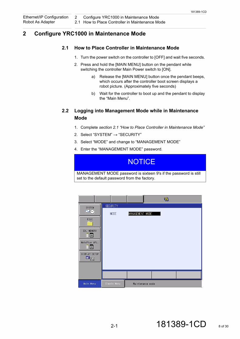
2. Select “SYSTEM” → “SECURITY”
3. Select “MODE” and change to “MANAGEMENT MODE”
4. Enter the “MANAGEMENT MODE” password.
NOTICE
MANAGEMENT MODE password is sixteen 9's if the password is still set to the default password from the factory.
2-1 181389-1CD 8 of 30
181389-1CD
2 Configure YRC1000 in Maintenance Mode2.3 How to View LAN Interface Settings
Ethernet/IP Configuration Robot As Adapter
2.3 How to View LAN Interface Settings
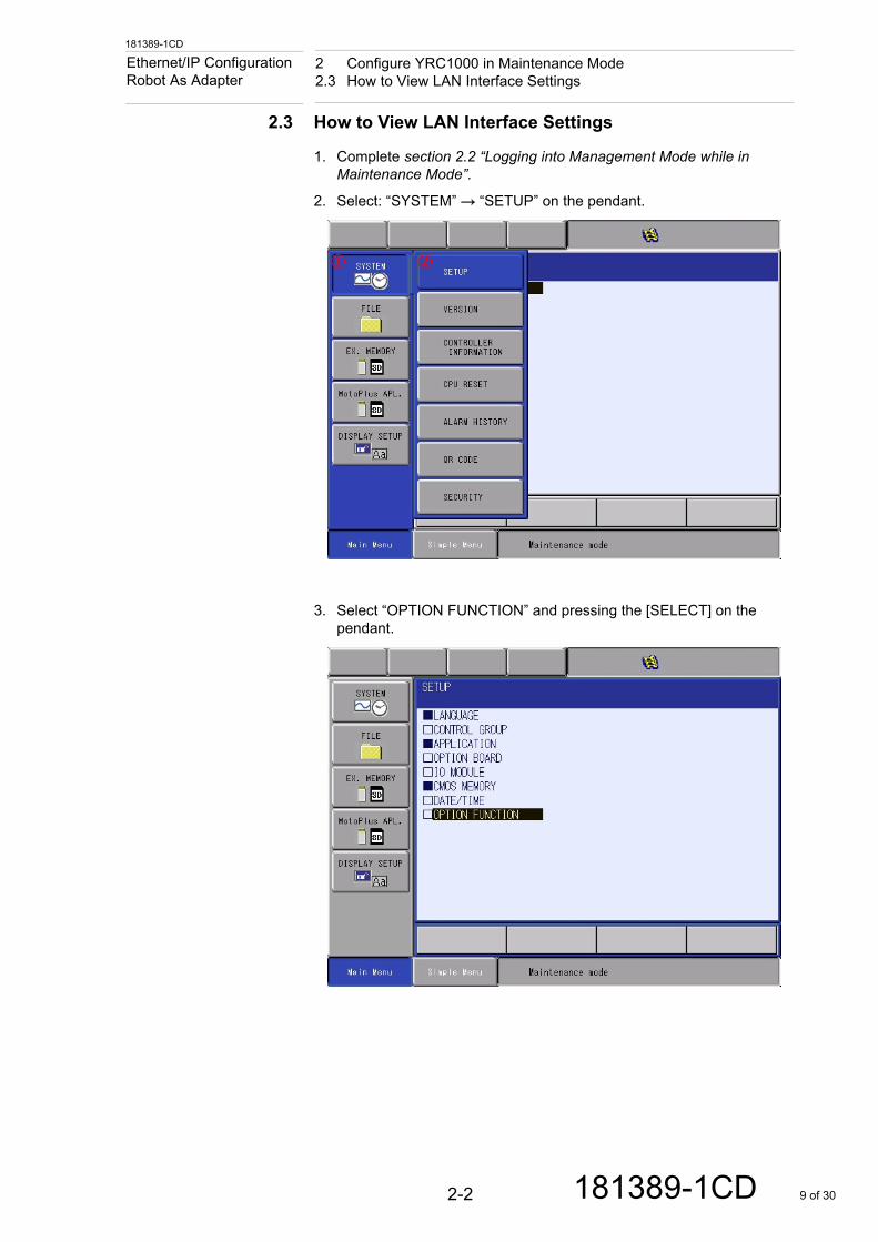
1. Complete section 2.2 “Logging into Management Mode while in Maintenance Mode”.
2. Select: “SYSTEM” → “SETUP” on the pendant.
3. Select “OPTION FUNCTION” and pressing the [SELECT] on the pendant.
2-2 181389-1CD 9 of 30

181389-1CD
2 Configure YRC1000 in Maintenance Mode2.3 How to View LAN Interface Settings
Ethernet/IP Configuration Robot As Adapter
4. Highlight “DETAIL” for “LAN INTERFACE SETTING” and press [SELECT] on the pendant.
5. Review the following information on the “LAN INTERFACE SETTING” screen:
• Host Settings • IP Address Settings
• Domain Settings • Default Gateway Settings
2-3 181389-1CD 10 of 30
181389-1CD
2 Configure YRC1000 in Maintenance Mode2.3 How to View LAN Interface Settings
Ethernet/IP Configuration Robot As Adapter
NOTICE
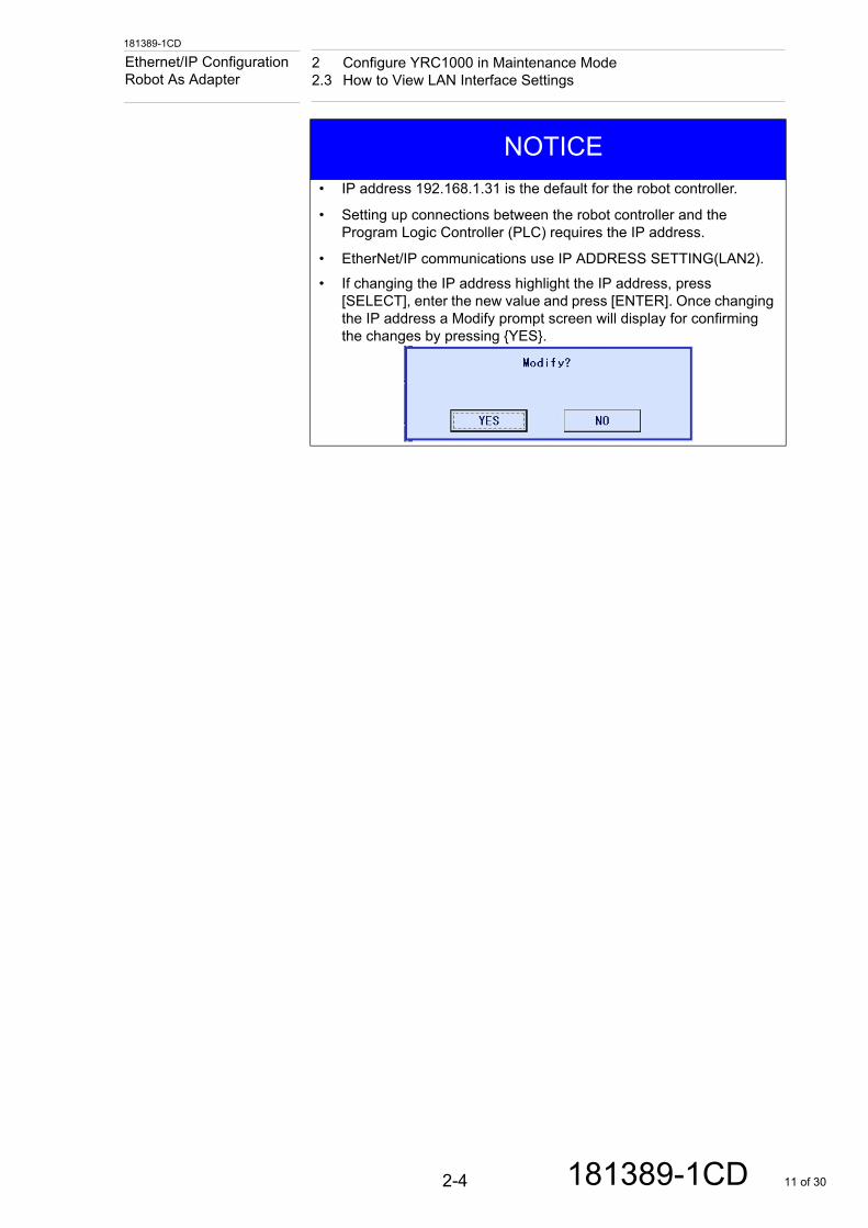
• IP address 192.168.1.31 is the default for the robot controller.
• Setting up connections between the robot controller and the Program Logic Controller (PLC) requires the IP address.
• EtherNet/IP communications use IP ADDRESS SETTING(LAN2).
• If changing the IP address highlight the IP address, press [SELECT], enter the new value and press [ENTER]. Once changing the IP address a Modify prompt screen will display for confirming the changes by pressing {YES}.
2-4 181389-1CD 11 of 30
181389-1CD
2 Configure YRC1000 in Maintenance Mode2.4 How to View EtherNet/IP (CPU Board) Settings
Ethernet/IP Configuration Robot As Adapter
2.4 How to View EtherNet/IP (CPU Board) Settings
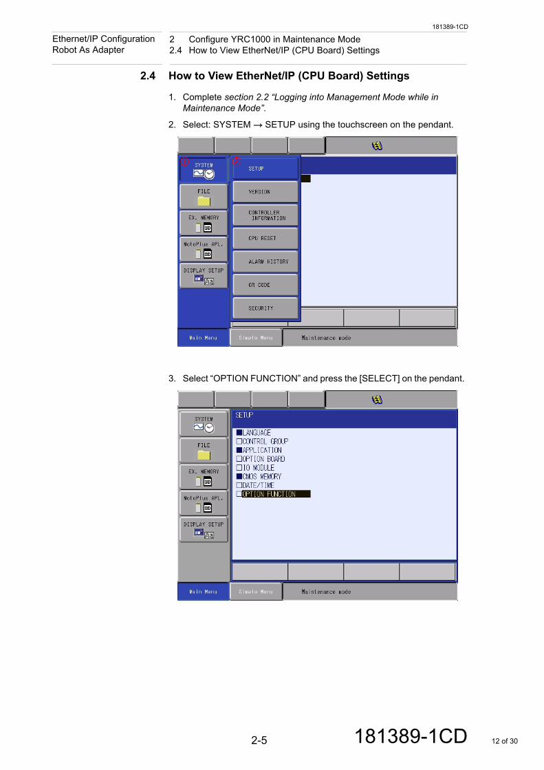
1. Complete section 2.2 “Logging into Management Mode while in Maintenance Mode”.
2. Select: SYSTEM → SETUP using the touchscreen on the pendant.
3. Select “OPTION FUNCTION” and press the [SELECT] on the pendant.
2-5 181389-1CD 12 of 30
181389-1CD
2 Configure YRC1000 in Maintenance Mode2.4 How to View EtherNet/IP (CPU Board) Settings
Ethernet/IP Configuration Robot As Adapter
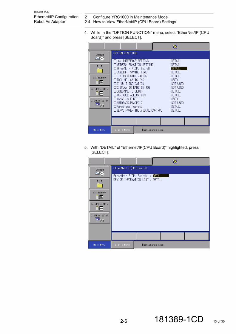
4. While In the “OPTION FUNCTION” menu, select “EtherNet/IP (CPU Board)” and press [SELECT].
5. With “DETAIL” of “Ethernet/IP(CPU Board)” highlighted, press [SELECT].
2-6 181389-1CD 13 of 30
181389-1CD
2 Configure YRC1000 in Maintenance Mode2.4 How to View EtherNet/IP (CPU Board) Settings
Ethernet/IP Configuration Robot As Adapter
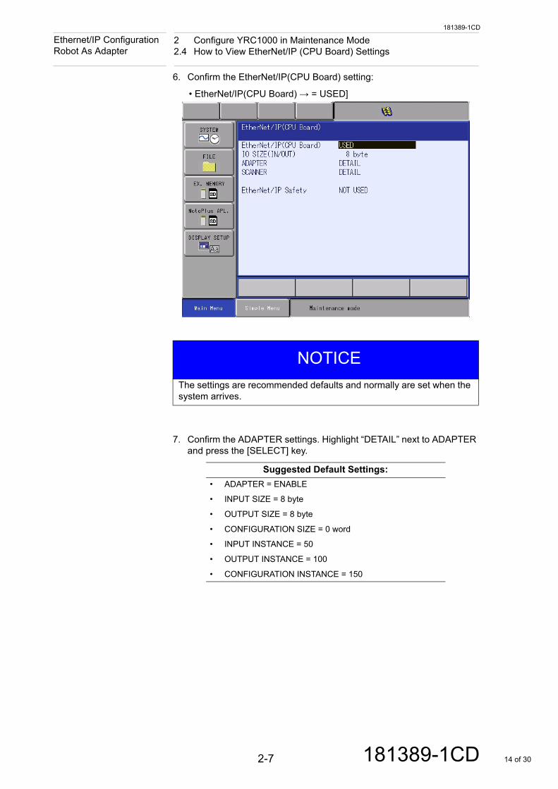
6. Confirm the EtherNet/IP(CPU Board) setting:
• EtherNet/IP(CPU Board) → = USED]
7. Confirm the ADAPTER settings. Highlight “DETAIL” next to ADAPTER and press the [SELECT] key.
NOTICE
The settings are recommended defaults and normally are set when the system arrives.
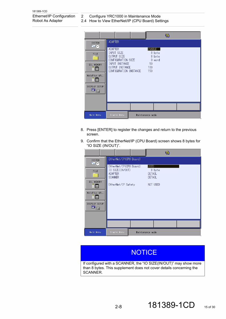
Suggested Default Settings:
• ADAPTER = ENABLE
• INPUT SIZE = 8 byte
• OUTPUT SIZE = 8 byte
• CONFIGURATION SIZE = 0 word
• INPUT INSTANCE = 50
• OUTPUT INSTANCE = 100
• CONFIGURATION INSTANCE = 150
2-7 181389-1CD 14 of 30
181389-1CD
2 Configure YRC1000 in Maintenance Mode2.4 How to View EtherNet/IP (CPU Board) Settings
Ethernet/IP Configuration Robot As Adapter
8. Press [ENTER] to register the changes and return to the previous screen.
9. Confirm that the EtherNet/IP (CPU Board) screen shows 8 bytes for “IO SIZE (IN/OUT)”.
NOTICE
If configured with a SCANNER, the “IO SIZE(IN/OUT)” may show more than 8 bytes. This supplement does not cover details concerning the SCANNER.
2-8 181389-1CD 15 of 30
181389-1CD
2 Configure YRC1000 in Maintenance Mode2.4 How to View EtherNet/IP (CPU Board) Settings
Ethernet/IP Configuration Robot As Adapter
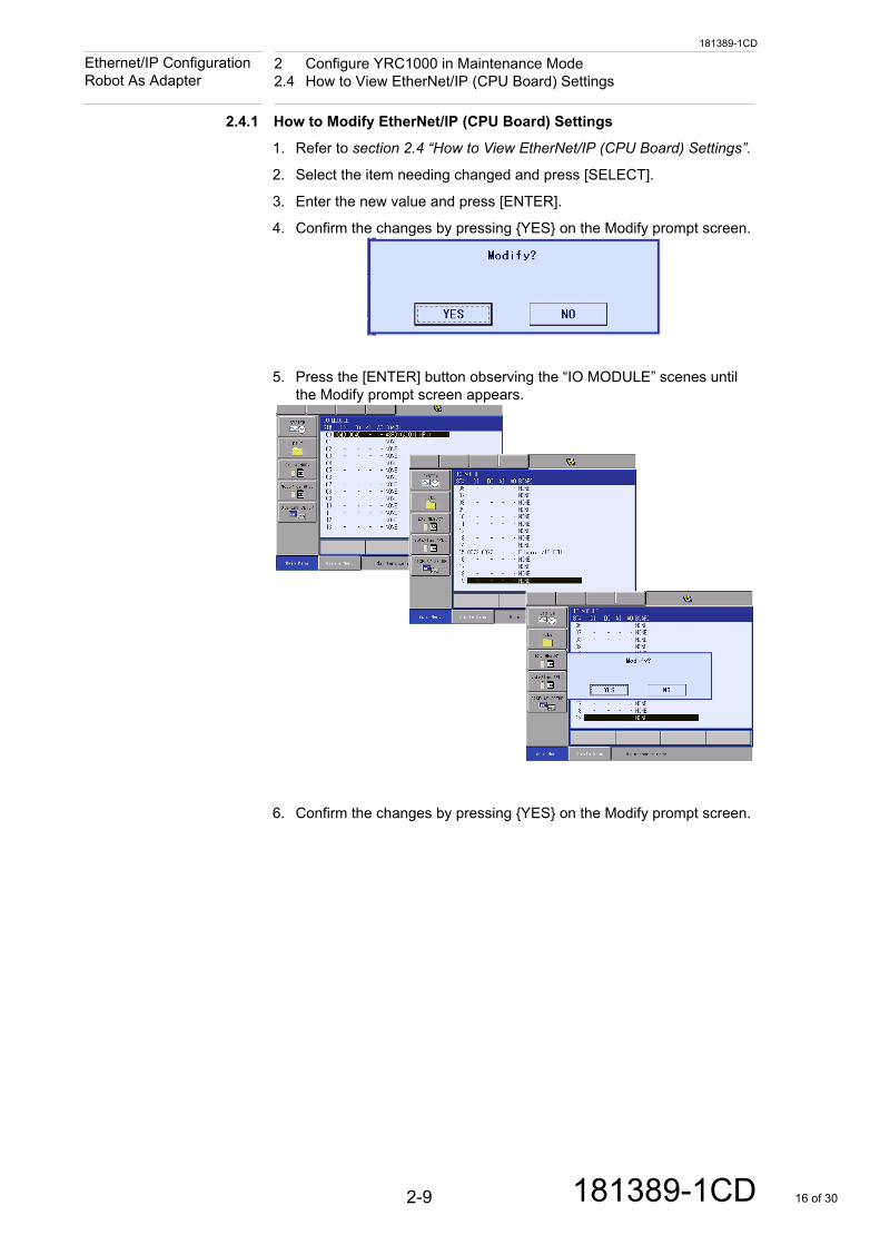
2.4.1 How to Modify EtherNet/IP (CPU Board) Settings
1. Refer to section 2.4 “How to View EtherNet/IP (CPU Board) Settings”.
2. Select the item needing changed and press [SELECT].
3. Enter the new value and press [ENTER].
4. Confirm the changes by pressing {YES} on the Modify prompt screen.
5. Press the [ENTER] button observing the “IO MODULE” scenes until the Modify prompt screen appears.
6. Confirm the changes by pressing {YES} on the Modify prompt screen.
2-9 181389-1CD 16 of 30
181389-1CD
2 Configure YRC1000 in Maintenance Mode2.4 How to View EtherNet/IP (CPU Board) Settings
Ethernet/IP Configuration Robot As Adapter
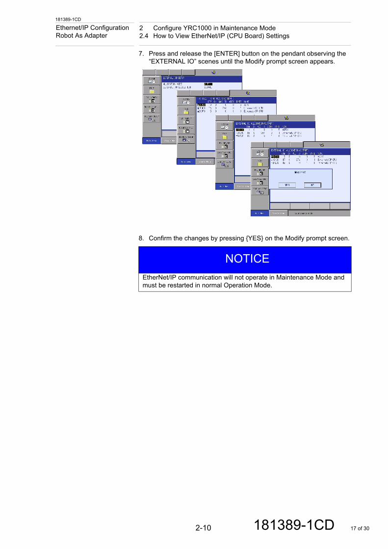
7. Press and release the [ENTER] button on the pendant observing the “EXTERNAL IO” scenes until the Modify prompt screen appears.
8. Confirm the changes by pressing {YES} on the Modify prompt screen.
NOTICE
EtherNet/IP communication will not operate in Maintenance Mode and must be restarted in normal Operation Mode.
2-10 181389-1CD 17 of 30
181389-1CD
2 Configure YRC1000 in Maintenance Mode2.5 Restarting Controller in Normal Operation Mode
Ethernet/IP Configuration Robot As Adapter
2.5 Restarting Controller in Normal Operation Mode
There are two ways to restart the robot controller in Normal Operation Mode. The two ways to restart the controller in Normal Operation Mode are through a power reset or a CPU reset.
2.5.1 Power Reset
1. Cycle the Main Disconnect from Off to back On
2.5.2 CPU Reset
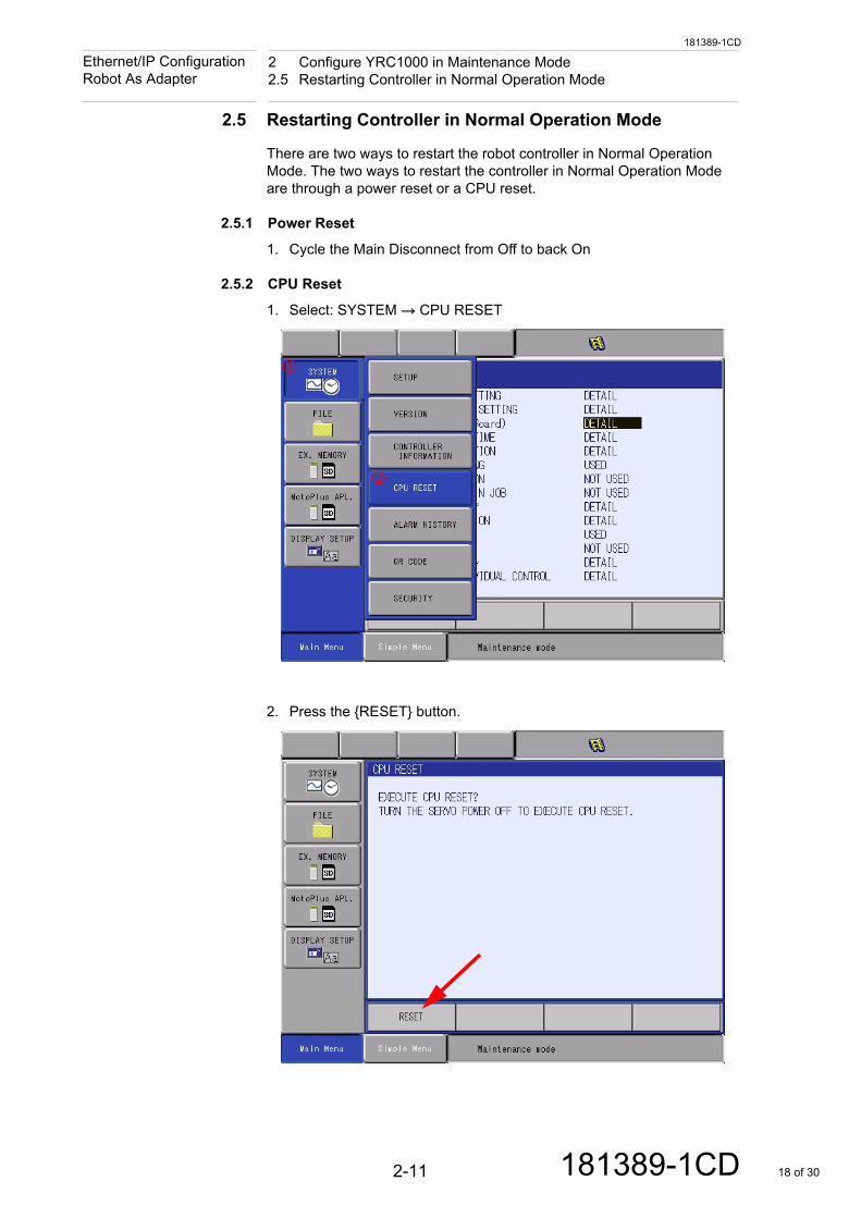
1. Select: SYSTEM → CPU RESET
2. Press the {RESET} button.
2-11 181389-1CD 18 of 30
181389-1CD
2 Configure YRC1000 in Maintenance Mode2.5 Restarting Controller in Normal Operation Mode
Ethernet/IP Configuration Robot As Adapter
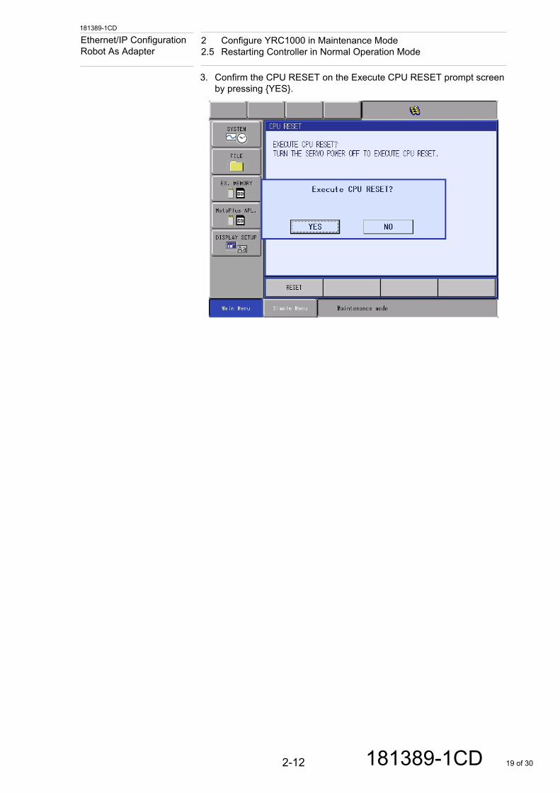
3. Confirm the CPU RESET on the Execute CPU RESET prompt screen by pressing {YES}.
2-12 181389-1CD 19 of 30
181389-1CD
3 Configuring PLC with RSLogix 5000 or Studio 5000Ethernet/IP Configuration Robot As Adapter
3 Configuring PLC with RSLogix 5000 or Studio 5000
Before beginning to configure the PLC complete Chapter 2 “Configure YRC1000 in Maintenance Mode”
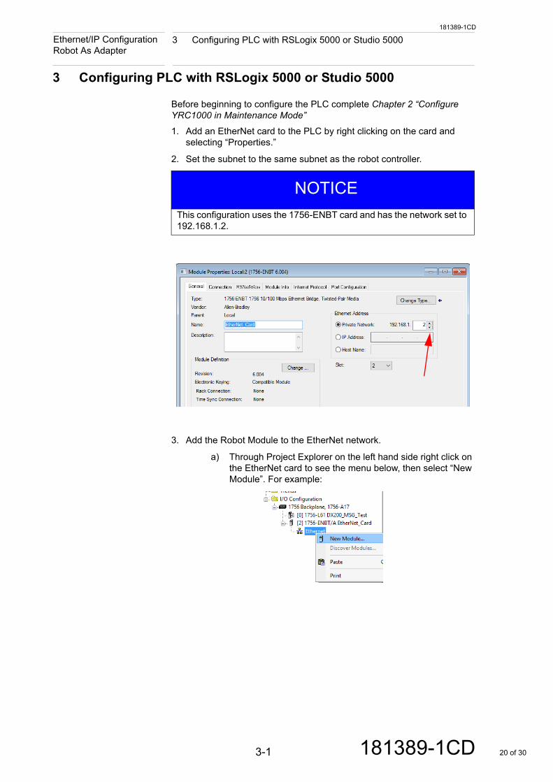
1. Add an EtherNet card to the PLC by right clicking on the card and selecting “Properties.”
2. Set the subnet to the same subnet as the robot controller.
3. Add the Robot Module to the EtherNet network.
a) Through Project Explorer on the left hand side right click on the EtherNet card to see the menu below, then select “New Module”. For example:
NOTICE
This configuration uses the 1756-ENBT card and has the network set to 192.168.1.2.
3-1 181389-1CD 20 of 30
181389-1CD
3 Configuring PLC with RSLogix 5000 or Studio 5000Ethernet/IP Configuration Robot As Adapter
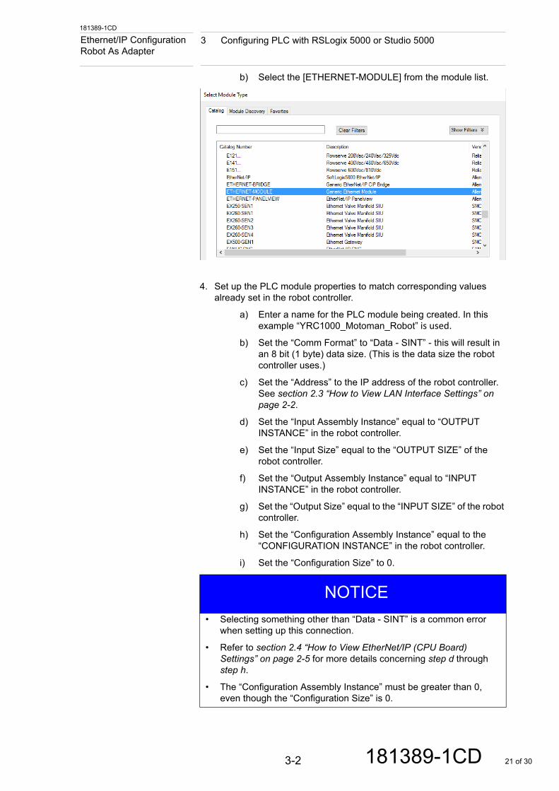
b) Select the [ETHERNET-MODULE] from the module list.
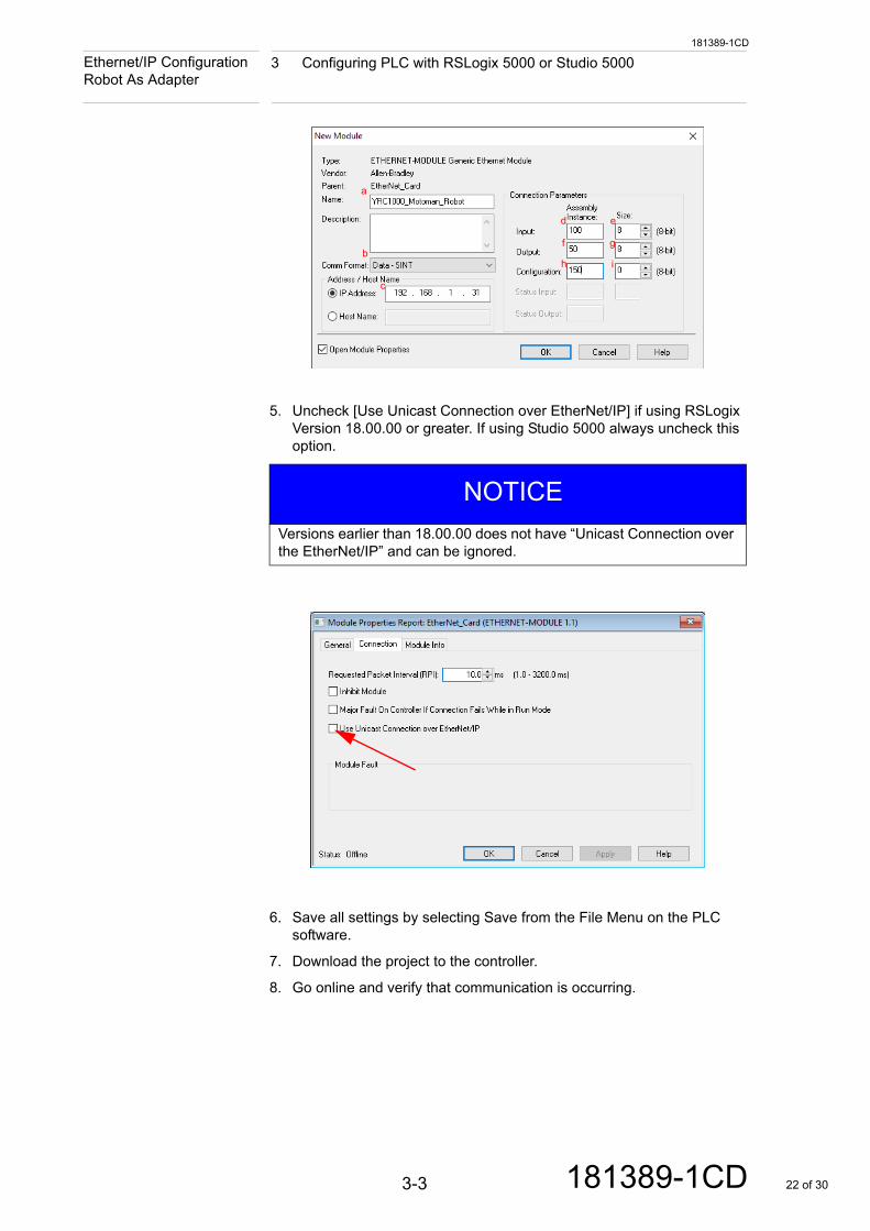
4. Set up the PLC module properties to match corresponding values already set in the robot controller.
a) Enter a name for the PLC module being created. In this example “YRC1000_Motoman_Robot” is used.
b) Set the “Comm Format” to “Data - SINT” - this will result in an 8 bit (1 byte) data size. (This is the data size the robot controller uses.)
c) Set the “Address” to the IP address of the robot controller. See section 2.3 “How to View LAN Interface Settings” on page 2-2.
d) Set the “Input Assembly Instance” equal to “OUTPUT INSTANCE” in the robot controller.
e) Set the “Input Size” equal to the “OUTPUT SIZE” of the robot controller.
f) Set the “Output Assembly Instance” equal to “INPUT INSTANCE” in the robot controller.
g) Set the “Output Size” equal to the “INPUT SIZE” of the robot controller.
h) Set the “Configuration Assembly Instance” equal to the “CONFIGURATION INSTANCE” in the robot controller.
i) Set the “Configuration Size” to 0.
NOTICE
• Selecting something other than “Data - SINT” is a common error when setting up this connection.
• Refer to section 2.4 “How to View EtherNet/IP (CPU Board) Settings” on page 2-5 for more details concerning step d through step h.
• The “Configuration Assembly Instance” must be greater than 0, even though the “Configuration Size” is 0.
3-2 181389-1CD 21 of 30
181389-1CD
3 Configuring PLC with RSLogix 5000 or Studio 5000Ethernet/IP Configuration Robot As Adapter
5. Uncheck [Use Unicast Connection over EtherNet/IP] if using RSLogix Version 18.00.00 or greater. If using Studio 5000 always uncheck this option.
6. Save all settings by selecting Save from the File Menu on the PLC software.
7. Download the project to the controller.
8. Go online and verify that communication is occurring.
NOTICE
Versions earlier than 18.00.00 does not have “Unicast Connection over the EtherNet/IP” and can be ignored.
a
b
c
d e
f g
h i
3-3 181389-1CD 22 of 30
181389-1CD
3 Configuring PLC with RSLogix 5000 or Studio 5000Ethernet/IP Configuration Robot As Adapter
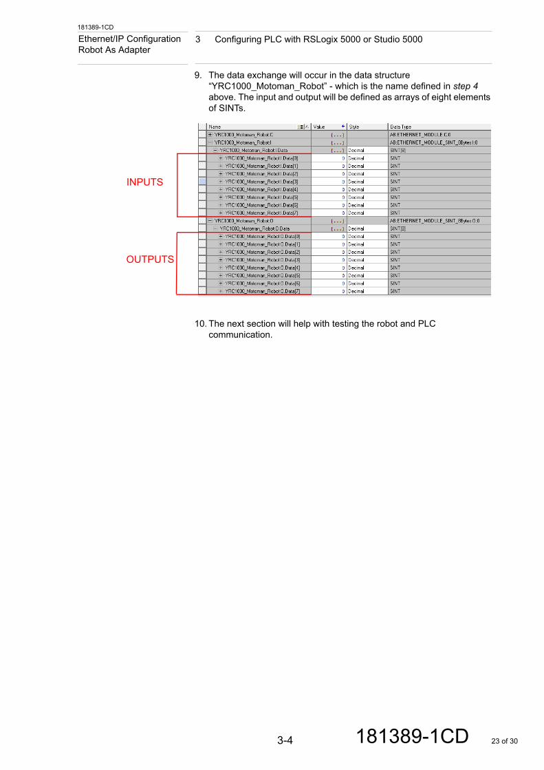
9. The data exchange will occur in the data structure “YRC1000_Motoman_Robot” - which is the name defined in step 4 above. The input and output will be defined as arrays of eight elements of SINTs.
10. The next section will help with testing the robot and PLC communication.
INPUTS
OUTPUTS
3-4 181389-1CD 23 of 30
181389-1CD
4 Configuration Testing4.1 Checking PLC Software Functional Communication
Ethernet/IP Configuration Robot As Adapter
4 Configuration Testing
Before beginning to testing the configurations make sure to complete Chapter 3 “Configuring PLC with RSLogix 5000 or Studio 5000”.
4.1 Checking PLC Software Functional Communication
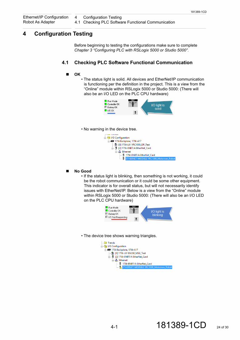
OK• The status light is solid. All devices and EtherNet/IP communication
is functioning per the definition in the project. This is a view from the “Online” module within RSLogix 5000 or Studio 5000: (There will also be an I/O LED on the PLC CPU hardware)
• No warning in the device tree.
No Good• If the status light is blinking, then something is not working, it could
be the robot communication or it could be some other equipment. This indicator is for overall status, but will not necessarily identify issues with EtherNet/IP. Below is a view from the “Online” module within RSLogix 5000 or Studio 5000: (There will also be an I/O LED on the PLC CPU hardware)
• The device tree shows warning triangles.
4-1 181389-1CD 24 of 30
181389-1CD
4 Configuration Testing4.2 Checking Robot Controller for Status Byte Communication Errors
Ethernet/IP Configuration Robot As Adapter
4.2 Checking Robot Controller for Status Byte
Communication Errors
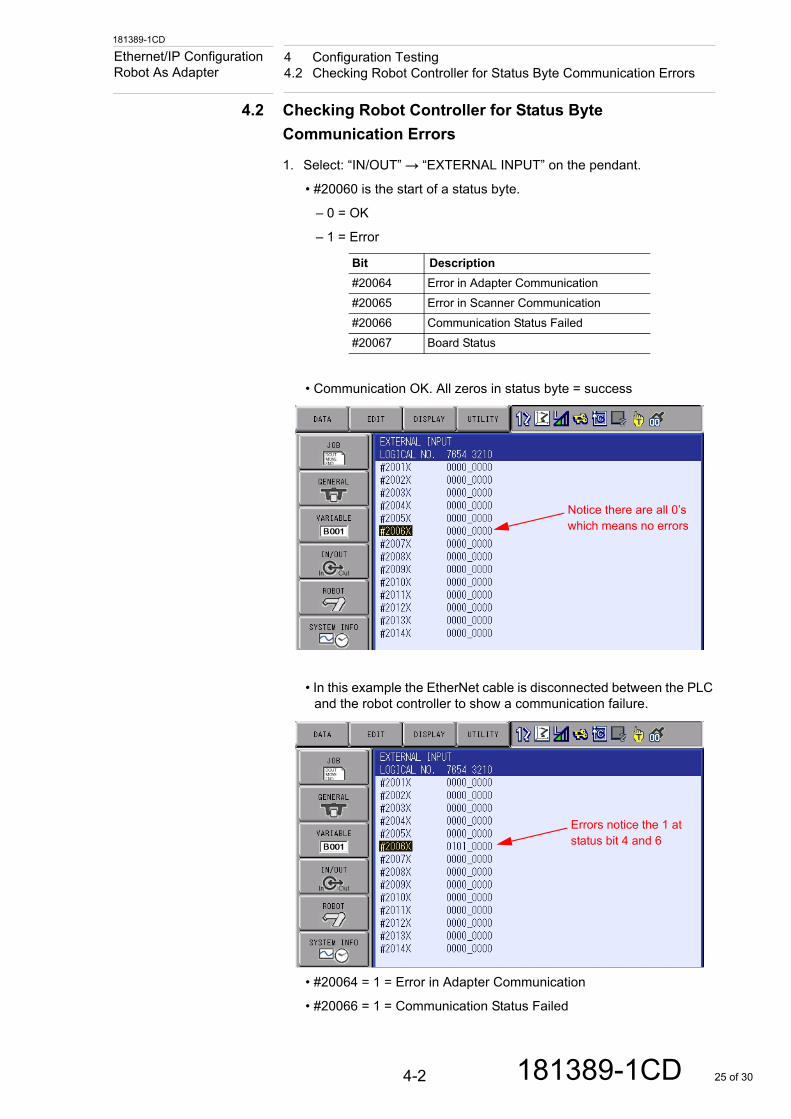
1. Select: “IN/OUT” → “EXTERNAL INPUT” on the pendant.
• #20060 is the start of a status byte.
– 0 = OK
– 1 = Error
• Communication OK. All zeros in status byte = success
• In this example the EtherNet cable is disconnected between the PLC and the robot controller to show a communication failure.
• #20064 = 1 = Error in Adapter Communication
• #20066 = 1 = Communication Status Failed
Bit Description
#20064 Error in Adapter Communication
#20065 Error in Scanner Communication
#20066 Communication Status Failed
#20067 Board Status
Notice there are all 0’s which means no errors
Errors notice the 1 at status bit 4 and 6
4-2 181389-1CD 25 of 30
181389-1CD
4 Configuration Testing4.3 EtherNet/IP Only Communication Standard Addresses
Ethernet/IP Configuration Robot As Adapter
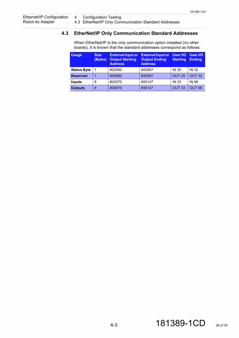
4.3 EtherNet/IP Only Communication Standard Addresses
When EtherNet/IP is the only communication option installed (no other boards), it is known that the standard addresses correspond as follows:
Usage Size (Bytes)
External Input or Output Starting Address
External Input or Output Ending Address
User I/O Starting
User I/O Ending
Status Byte 1 #20060 #20067 IN 25 IN 32
Reserved 1 #30060 #30067 OUT 25 OUT 32
Inputs 8 #20070 #20147 IN 33 IN 96
Outputs 8 #30070 #30147 OUT 33 OUT 96
4-3 181389-1CD 26 of 30
181389-1CD
4 Configuration Testing4.4 Verifying Robot Controller Outputs with PLC Inputs
Ethernet/IP Configuration Robot As Adapter
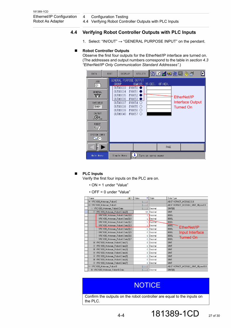
4.4 Verifying Robot Controller Outputs with PLC Inputs
1. Select: “IN/OUT” → “GENERAL PURPOSE INPUT” on the pendant.
Robot Controller OutputsObserve the first four outputs for the EtherNet/IP interface are turned on. (The addresses and output numbers correspond to the table in section 4.3 “EtherNet/IP Only Communication Standard Addresses”.)
PLC InputsVerify the first four inputs on the PLC are on.
• ON = 1 under “Value”
• OFF = 0 under “Value”
EtherNet/IP Interface Output Turned On
NOTICE
Confirm the outputs on the robot controller are equal to the inputs on the PLC.
EtherNet/IP Input Interface Turned On
4-4 181389-1CD 27 of 30
181389-1CD
4 Configuration Testing4.5 Verifying PLC Outputs with Robot Controller Inputs
Ethernet/IP Configuration Robot As Adapter
4.5 Verifying PLC Outputs with Robot Controller Inputs
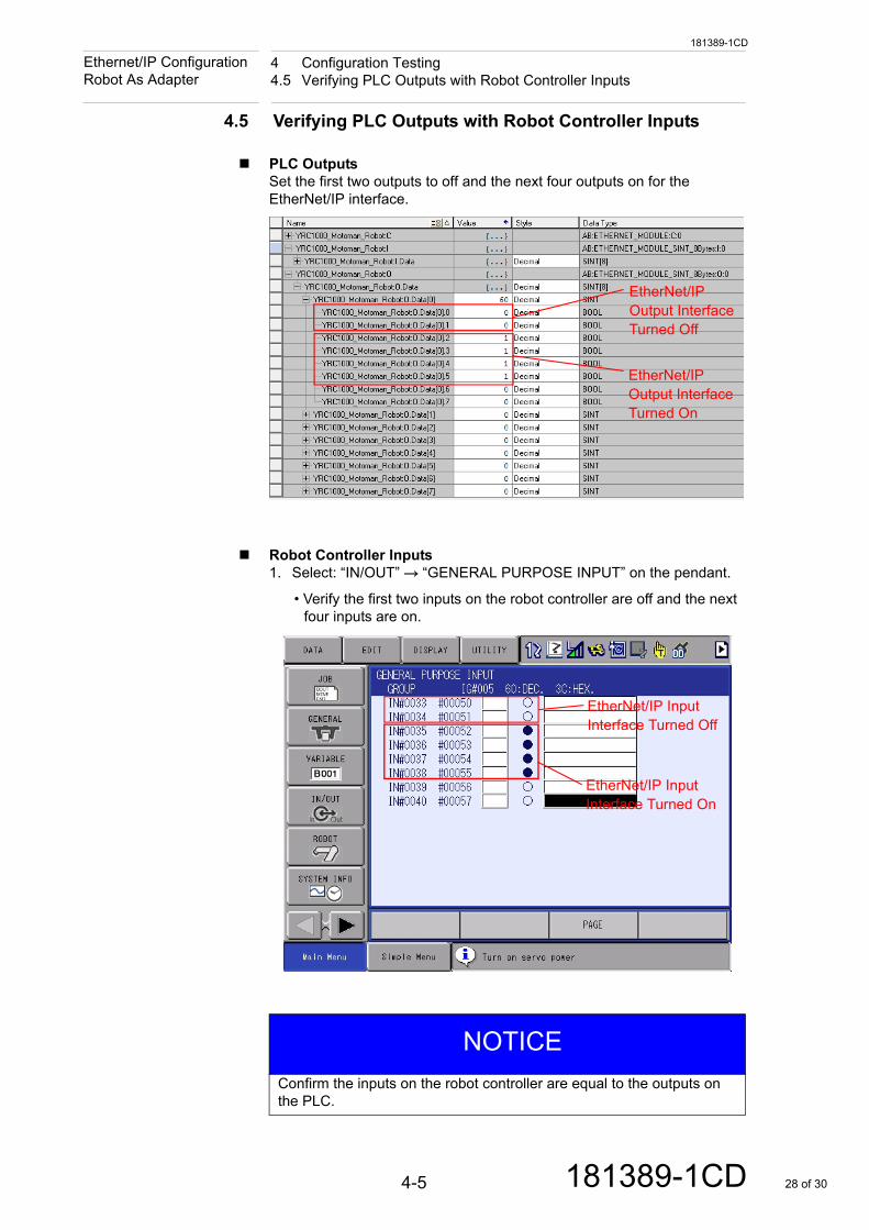
PLC OutputsSet the first two outputs to off and the next four outputs on for the EtherNet/IP interface.
Robot Controller Inputs1. Select: “IN/OUT” → “GENERAL PURPOSE INPUT” on the pendant.
• Verify the first two inputs on the robot controller are off and the next four inputs are on.
EtherNet/IP Output Interface Turned Off
EtherNet/IP Output Interface Turned On
NOTICE
Confirm the inputs on the robot controller are equal to the outputs on the PLC.
EtherNet/IP Input Interface Turned Off
EtherNet/IP Input Interface Turned On
4-5 181389-1CD 28 of 30
A-1
181389-1CD
181389-1CD
Appendix AA.1 Notes on Configurations
Ethernet/IP Configuration Robot As Adapter
Appendix A
A.1 Notes on Configurations
(1) The steps and parameters in this supplement are for a successful EtherNet/IP integration and communication solution.
(2) This guide shows 8 bytes of input data and 8 bytes of output as a starting point for data exchange. Some configurations require smaller or larger quantities of input and output data. For those circumstances make the appropriate adjustments to both the PLC and Robot controller steps.
(3) When requiring an IP address outside the subnet 192.168.1.*** make the appropriate changes on the PLC, robot, or other networking equipment.
(4) In addition to the status byte on the robot controller, it is typical to add a “heart beat” between the robot and PLC to detect when communication has failed. This logic is left to the end user.
(5) After establishing communication, it is often desirable to “map” some specific input and output signals from the robot’s Concurrent I/O (ladder) to the PLC. This guide does not cover these operations, but various support groups at YASKAWA can assist.
29 of 30
ETHERNET/IP CONFIGURATIONROBOT AS ADAPTERSUPPLEMENT
HEAD OFFICE2-1 Kurosakishiroishi, Yahatanishi-ku, Kitakyushu 806-0004, JapanPhone +81-93-645-7703 Fax +81-93-645-7802
100 Automation Way, Miamisburg, OH 45342, U.S.A. Phone +1-937-847-6200 Fax +1-937-847-6277
YASKAWA America Inc. (Motoman Robotics Division)
Yaskawastrasse 1, 85391 Allershausen, GermanyPhone +49-8166-90-100 Fax +49-8166-90-103
YASKAWA Europe GmbH Robotics Divsion )
Phone +82-2-784-7844 Fax +82-2-784-8495
151 Lorong Chuan, #04-02A, New Tech Park, Singapore 556741Phone +65-6282-3003 Fax +65-6289-3003
YASKAWA Electric (Singapore) PTE Ltd.
No7 Yongchang North Road, Beijing E&T Development Area China 100176Phone +86-10-6788-2858 Fax +86-10-6788-2878
YASKAWA SHOUGANG ROBOT Co. Ltd.
#426, Udyog Vihar, Phase- IV, Gurgaon, Haryana, IndiaFax +91-124-475-8542Phone +91-124-475-8500
YASKAWA India Private Ltd. (Robotics Division)
YASKAWA Electric (China) Co., Ltd.22F, One Corporate Avenue, No.222, Hubin Road, Huangpu District, Shanghai 200021, ChinaPhone +86-21-5385-2200 Fax 86-21-5385-3299
YASKAWA Electric (Thailand) Co., Ltd.59,1st-5th Floor, Flourish Building, Soi Ratchadapisek 18,Ratchadapisek Road, Huaykwang, Bangkok 10310, THAILANDPhone +66-2-017-0099 Fax +66-2-017-0199
12F, No.207, Sec. 3, Beishin Rd., Shindian District, New Taipei City 23143, TaiwanFax +886-2-8913-1513Phone +886-2-8913-1333
YASKAWA Electric Taiwan Corporation
Secure Building-Gedung B Lantai Dasar & Lantai 1 JI. Raya Protokol Halim Perdanakusuma, Jakarta 13610, Indonesia
Fax +62-21-2982-6741Phone +62-21-2982-6470
PT. YASKAWA Electric Indonesia
Phone +46-480-417-800 Fax +46-486-414-10
YASKAWA Nordic ABVerkstadsgatan 2, Box 504 ,SE-385 25 Torsas, Sweden
35F, Three IFC, 10 Gukjegeumyung-ro, Yeongdeungpo-gu, Seoul, Korea 07326YASKAWA Electric Korea Corporation
181389-1CD
Specifications are subject to change without noticefor ongoing product modifications and improvements.
MANUAL NO.
30 of 30