ergonomic assessment of mammography units
TRANSCRIPT

ERGONOMIC ASSESSMENT OF MAMMOGRAPHY UNITS
NHSBSP Equipment Report 0708October 2007
AG Gale, N Hunter, C Lawton and K PurdyApplied Vision Research Centre, Loughborough University

EnquiriesEnquiries about this report should be addressed to:Professor Alastair Gale Applied Vision Research Centre Loughborough University Loughborough Leicestershire LE11 3UZ
Tel: 01509 63 5703Fax: 01509 63 5709Email: [email protected]
Published byNHS Cancer Screening ProgrammesFulwood HouseOld Fulwood RoadSheffieldS10 3TH
Tel:0114 271 1060Fax: 0114 271 1089Email: [email protected]: www.cancerscreening.nhs.uk
© NHS Cancer Screening Programmes 2007
The contents of this document may be copied for use by staff working in the public sector but may not be copied for any other purpose without prior permission from the NHS Cancer Screening Programmes.The report is available in PDF format on the NHS Cancer Screening Programmes’ website.
Further copiesRequests for further copies should be made to the Department of Health Publications Orderline, quoting NHSBSP Equipment Report 0708.Tel: 08701 555 455Fax: 01623 724 524Email: [email protected]
Typeset by Prepress Projects Ltd, Perth (www.prepress-projects.co.uk) Printed by Charlesworth

NHSBSP October 2007 iii
Ergonomic Assessment of Mammography Units
CONTENTS
Page No
ExECUTiVE SUmmARy 1
1. iNTRODUCTiON 3
1.1 Background 31.2 Scope 41.3 Changes since the previous report 4
2. ASSESSmENT OF mAmmOGRAPHy UNiTS iN CURRENT USE 7
2.1 Comparison of current units with previous recommendations 72.2 Additional observations 35
3. ANALySiS OF THE CURRENT BREAST SCREENiNG TASK 41
3.1 Current Study 413.2 Background information 423.3 Postural assessment 453.4 Task analysis 52
4. SUmmARy AND CONCLUSiONS 55
4.1 Assessment and comparison of current units with 1997 report 554.2 Analysis of the current breast screening task 574.3 Potential future work 59
APPENDix 1: DETAiLED TASK ELEmENTS FOR POSTURAL ANALySiS 61
APPENDix 2: TASK ANALySiS CHARTS 73

Ergonomic Assessment of Mammography Units
NHSBSP October 2007 iv

NHSBSP October 2007 �
Ergonomic Assessment of Mammography Units
ExECUTIVE SUMMARY
An ergonomic assessment of mammography machines was previously carried out for the NHS Breast Screen-ing Programme in 1997.* Since 1997, some basic changes have occurred to many mammography machines and their associated hardware (referred to in this report as ‘units’) that have reduced the frequency with which harmful tasks are carried out. These include developments such as the introduction of motorised units, lightweight units with isocentric rotation and the provision of more accessible controls. When implemented properly, all of these developments can serve to make the mammography task less physically demanding for the mammography practitioner.
Some recommendations in the 1997 report have not been taken up by manufacturers, eg non-reflective glare on compression paddles or motorised tube heads. it is likely that a number of factors have contributed to this, such as cost, feasibility and development time. Overall, mammography units are more ergonomic, but there are variations in design between different manufacturers and some issues still need to be addressed.Consultation with the NHS Breast Screening Programme (NHSBSP) and discussion with both individual mammography practitioners and regional training centres revealed that many mammography practitioners still experience musculoskeletal problems. Wrist, thumb and finger problems emerged as being most trouble-some in the groups studied. However, although such wrist/thumb problems were noted in 1997, they were not at that time considered to be as extensive as issues such as back problems. in combining injury reports with those received by the NHSBSP, it would appear that back, shoulder, elbow and knee problems are now less prevalent than wrist/thumb problems.
The remit of the current ergonomic assessment was to establish the present situation, identifying areas where improvement is needed and making recommendations for alteration to the 1997 report in order to achieve improvement. Consequently, this work concentrates more on current and future aspects than on specifying the exact degree or cause of improvement over past years. The 1997 set of recommendations was made to address the ergonomic challenges in a number of different ways, and so it is likely that a number of factors are responsible for the improvements seen since then.
As problems with areas of the lower limbs remain prevalent, and as some recommendations from the 1997 report have not been implemented, further measures may be required. in addition, although the levels of back and shoulder pain have reduced, it is still necessary to prevent a return to the previous situation and, ideally, to reduce levels further. Other factors such as the change in the mean age of the radiographer population and different work patterns may well be relevant too, and changes in the immediate future, such as the move towards digital capture, should be anticipated as far as is reasonably feasible.
The factors identified as causing wrist and hand pain are inserting and ejecting films from the bucky, control locations on handles, mounting film onto the viewer and changing the exposure chamber settings. Currently, digital technology is mostly used for symptomatic work, but it is expected to become widespread in the screen-ing programme. Digital mammography units reduce many of the factors thought to be causing wrist and hand pain, and so will in theory be beneficial in reducing this in the long term. However, some problematic aspects are being carried over from analogue to digital capture designs without notable improvement. The task of positioning the breast on the breast support table and exposing it still remains. it is these tasks which result in the most extreme and awkward postures and therefore where the highest risk of injury may occur.
* Gale AG, may J. An Evaluation of Musculoskeletal Discomfort Experienced by Radiographers Performing Mammography. NHS Breast Screening Programme 1997 (NHSBSP Publication No 36).

Ergonomic Assessment of Mammography Units
NHSBSP October 2007 2
There are also some new ergonomic issues related to digital technology that are potentially of concern. A small number of mammography practitioners have observed that when conducting the mediolateral view there may well be more excessive reaching and twisting with a digital unit than with an analogue unit; however, this has not been quantified. It has been suggested that this is due to the lower height and larger size of the head of the unit arm, which acts as a larger obstacle to mammography practitioners than the head of the analogue unit when viewing the breast.
There is a risk that the removal of some tasks will result in more frequent repetition of the remaining higher risk task elements. The removal of certain tasks will mean that the body is given fewer and/or shorter rest breaks from adopting awkward postures and between repeating the same actions. Currently, the task element of processing x-ray films provides a built in break, during which awkward postures are not adopted. With the removal of these physically less demanding tasks which encourage neutral postures, consideration needs to be given to how naturally occurring micro-pauses can be built into, and become part of, the digital task.

NHSBSP October 2007 �
Ergonomic Assessment of Mammography Units
�. INTROdUCTION
�.� Background
in 1997, the Applied Vision Research institute, University of Derby (now the Applied Vision Research Centre, Loughborough University)* examined whether radiographers performing mammography were experiencing musculoskeletal discomfort or injury and to what extent the design or layout of the equipment were potentially contributing factors.
The work involved a national questionnaire survey of radiographers to determine the extent of self-perceived musculoskeletal injury, a body map discomfort survey to examine the local areas of pain experienced by radio-graphers, taking physical measurements of mammography units and comparing these with the anthropometric measurements of radiographers, and finally conducting a task analysis of the mammography screening process to understand how the equipment was operated and to observe exactly where in the sequence of operation problems were occurring.
These approaches enabled researchers to understand the extent of musculoskeletal injury and to determine whether any association existed between the injuries and any areas of the equipment design or features of the task of performing mammography. in particular, these approaches allowed researchers to investigate the precise aspects of mammography that were subjecting radiographers to the four basic factors that harm the musculoskeletal system, ie excessive bending and twisting, static working postures, forceful movements and repetitive work.
As a result of these observations, a series of recommendations was proposed to improve the design of the mammography units. These recommendations aimed to reduce the frequency with which radiographers needed to adopt harmful postures. Additionally, a video tape was made to encourage radiographers to be aware of the potential for injury and to adopt appropriate postures.
Since then, there have been changes to many aspects of mammography and breast screening. manufacturers now stress what they consider to be the ergonomic features of their systems. As systems have become more ergonomic and less tiring to use, the situation as addressed by the 1997 report has changed. Although most of these changes are expected to be beneficial to both users and productivity levels, it should be recognised that such advantages may also introduce new issues to address, such as the need to account for the latest hardware configurations and the changing demands on users that could be associated with the increased speed and repetition that physical improvements may allow.
Additionally, several innovations have taken place, such as the introduction of digital acquisition technol-ogy, breast biopsy facilities and manufacturers’ bespoke systems that enable imaging of more breast tissue. Consequently, it has been suggested that it may be time to update the previous work, as these mammography imaging units have changed and may require somewhat different operating postures and related tasks.
This report details work that has been carried out since 1997 in order to address the new situation. For con-sistency and brevity, this report refers to mammography machines and any tools or hardware integral to them as ‘mammography units’.
* Gale AG, may J. An Evaluation of Musculoskeletal Discomfort Experienced by Radiographers Performing Mammography. NHS Breast Screening Programme 1997 (NHSBSP Publication No 36).

Ergonomic Assessment of Mammography Units
NHSBSP October 2007 �
�.2 Scope
As it is some time since the 1997 report was published, an updated version is required; however, only a certain degree of change was anticipated and hence this work essentially comprises an update and modernisation of the previous work rather than a full repeat of it. in particular, it was not thought necessary to carry out another national survey of mammography practitioners with regard to potential musculoskeletal injuries because the practitioners’ working situations have remained similar. Any amendments by manufacturers since the first survey should have been to improve the ergonomics of the equipment following the previous recommenda-tions. Therefore, smaller scale investigation, consultation and information from the NHSBSP have been used to direct attention to specific areas of concern. As a result, the current work comprised the following:
the previously published report was reviewed in light of developments in mammographic technologythe mammography units that are currently in use were identified along with which breast screening services are using themthese mammography units were compared with both the advice in the previously published report and the manufacturers’ ergonomic claims in their literature; this would quantify how well the unit meets the advice and how well the manufacturers comply with ittask analyses were carried out for a sample of mammography practitioners, representing upper and lower anthropometric percentiles, operating these mammography units; this identified any possible changes in the overall task since the previous report and also allowed evaluation of the current potential for musculoskeletal harm (eg repetitive strain injury (RSi) or work related upper limb disorder (WRULD)). The types of postures involved and the frequency of adopting such postures were determined.
�.� Changes since the previous report
1.3.1 Musculoskeletal problems
The 1997 report highlighted that musculoskeletal injuries were particularly affecting body areas such as the shoulders, back, elbows and knees. A series of recommendations were proposed regarding the technique that mammography practitioners should adopt when using the equipment. This may have contributed to the reduc-tion in reports of this type of musculoskeletal complaint by making mammography practitioners more aware of the risks posed by mammography and how best to ameliorate them.
However, correspondence with the NHSBSP and individual breast screening units has revealed that musculo-skeletal injury and, in particular, RSi affecting the thumbs and wrists remains a particular problem for mam-mography practitioners. The fact that musculoskeletal pain (particularly in the thumbs and wrists) remains a problem rightly concerns the NHSBSP and, consequently, this report examines those mammography machines currently in use.
••
•
•

NHSBSP October 2007 �
Ergonomic Assessment of Mammography Units
1.3.2 Past and current mammography units
The mammography units examined by the 1997 report are listed below:
GE Senographe 600T
Lorad mark iii
GE Senographe DmR
Siemens mammomat 2
mamex DCS
Picker Sureview
Philips mammoDiagnost UC
Philips mammoDiagnost Um
As can be seen from the following list, very few of the mammography units in use in 1997 are still currently used in the NHSBSP:
Number of units in useSiemens mammomat 3000 211
Lorad mark iV 81
GE 800T 66
GE DmR+ 65
instrumentarium Alpha RT 17
Siemens mammomat 300 8
instrumentarium Diamond 6
Siemens mammomat 1000 5
instrumentarium Performa 4
Siemens mammomat 2/2S 4
Planmed Sophie 4
Philips mammoDiagnost S 1
Siemens mammomat 3 1
This information was compiled in July 2004 (source: NHSBSP Equipment Fault Report: December 2003 to May 2004).
it is clear that the 1997 report is now outmoded with respect to the majority of equipment currently used in the NHSBSP. Therefore, it is important to examine what design changes have been made to mammography equipment since the previous report was published in 1997.

Ergonomic Assessment of Mammography Units
NHSBSP October 2007 �

NHSBSP October 2007 7
Ergonomic Assessment of Mammography Units
2. ASSESSMENT OF MAMMOGRAPHY UNITS IN CURRENT USE
2.� Comparison of current units with previous recommendations
The purpose of this section is to compare the recommendations made in the 1997 NHSBSP report with the current ergonomic situation, including assessment both of the units themselves and of their manufacturers’ literature. This will indicate areas of the 1997 report that have been acted upon successfully in the design of new units, and also where there are still issues to be addressed.
For the purposes of this work, the following mammographic units have been examined: Alpha RT, GE 800T, GE DmR+, instrumentarium Diamond, Lorad mark iV and the Siemens mammomat 3000. These units include the four most popular models in the NHSBSP (by quite some margin), and together they account for over 95% of the units used in the programme (source: NHSBSP Equipment Fault Report December 2003 to May 2004; information taken in July 2004).
The units listed above have all been investigated using the same set of criteria. The recommendations made in the 1997 report highlighted areas where the design of the units could have been improved. Because these recommendations were listed as a means to inform future equipment design, they are being used here as a broad set of criteria to evaluate the current equipment. The design recommendations made in the 1997 report have been included (in italics) as a reference for comparison with current equipment.
2.1.1 Tube head placement
When the tube head is rotated (particularly when taking the medio-lateral view), the radiographer has to bend underneath it to view and position the breast. Investigations should be conducted to try to identify different positions of the tube head relative to the breast support table. Possible solution is to have a tube head that ‘rotates’ away from the C-arm to provide the space for the radiographer to position the breast.
The Instrumentarium diamond has a ‘park away’ tube head feature (Figures 1–3). This enables the mam-mography practitioner to retract the tube head (away from the woman being imaged) to provide extra space for the mammography practitioner to operate. The feature is motorised and operates at the press of a button. This appears to have been intended to be used primarily for stereotactic examinations as it affords both the mammography practitioner and the woman being imaged more space during these examinations (which can be time consuming to prepare). However, the facility could also potentially be used when performing the mediolateral (mLO) view. Therefore, when the unit is rotated to 45° the mammography practitioner has more space around the tube head; however, she would still have to crouch below the tube head when positioning the breast, but this may offer slightly more space.
Although this can be ergonomically useful in some cases, it is not thought to be an ideal solution as the tube head does not retract fully away from the woman, which forces some mammography practitioners to continue to bend beneath the tube head during positioning. This feature could be developed further, however, such that the tube head fully retracts and completely removes the need for mammography practitioners to bend under the tube head.

Ergonomic Assessment of Mammography Units
NHSBSP October 2007 8
‘Parked back’
tube head
Side location of
‘park back’
control (another
is located on the
top of the tube
head)Tube head
Tube head rotation
controls (close up
view)
Tube head ‘park back’
control
Figure � instrumentarium Diamond showing head parking controls.
Figure 2 instrumentarium Diamond showing ‘parked’ head.

NHSBSP October 2007 �
Ergonomic Assessment of Mammography Units
The 1997 report highlighted this aspect of mammography as being one of the most harmful, particularly for the back and upper limbs. Any feature which reduces the need for mammography practitioners to bend should be welcomed.
None of the other units currently in use incorporates such a facility. All have similar structural features as those units examined in 1997. Although the effects can be minimised by awareness and postural training, this remains an area where mammography equipment design can be radically improved.
2.1.2 Unit controls
Controls should be located in positions where they cannot be accidentally operated, but are within easy reach of the operator such that she does not need to twist to locate and operate these.
A better design was highlighted where controls were located at both the top and bottom of the C-arm (enabling easy operation by all sizes of radiographer). Controls should also be placed on the top of the tube head for easier operation when the lateral view is taken.
Controls should be located towards the front of the tube head to limit the extent of reaching, bending and twisting the radiographer must perform when adjusting the height of the breast support table.
Controls placed on handles should be within easy reach of the position where the radiographer would usually grip the handle. This means that they do not have to stretch and position the hand and wrist awkwardly when gripping the C-arm and operating controls.
Controls should be easily located and be different in position, texture, shape and colour to aid easy identification, preferably without having to be visually detected.
Additional ‘park
back’ and tube head
rotation controls
Figure � instrumentarium Diamond showing parked and rotated head.

Ergonomic Assessment of Mammography Units
NHSBSP October 2007 �0
Since the 1997 report, it appears that manufacturers have recognised the need to locate controls within easy reach on the units, thus enabling mammography practitioners of differing sizes to operate them without having to reach or stretch excessively. This is good practice when done effectively, and has been achieved mostly through introducing multiple sets of controls on the units.
Units requiring the mammography practitioner to manually rotate the tube head to the desired angle have the rotation release buttons positioned on the handles. The mammography practitioner depresses the rotation release button and rotates the unit into position with the same hand. The GE 800T and the GE dMR+ both have two sets of controls on the handles, one at the bottom of the handle and one at the top (this allows tall and short mammography practitioners to operate the unit) (Figures 4 and 5). These are positioned towards the ends of the handles, thus giving maximum leverage around the point of rotation of the unit. A concern over locating controls on the handles is that mammography practitioners are forced to deviate the wrists when moving the unit into position. Generally, the handle is gripped and the thumb is used to operate the rotation lock control. When the unit is moved towards the endpoint of the rotation, this involves the wrist being deviated (either ulnar or radial deviation, depending on whether the bottom or top set of controls is used). Excessive and/or repetitive deviation of the wrist, especially when under load, can result in repetitive strain injury (RSi) and work related upper limb disorders (WRULDs).
Close up of unit
controls
Figure � GE DmR+ showing handle controls.
NHSBSP October 2007 ��
Ergonomic Assessment of Mammography Units
Height adjustment
controls and rotation
unlock buttons
(press then manually
rotate unit)
Additional
vertical height
adjustment
button
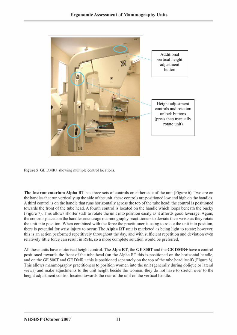
Figure � GE DmR+ showing multiple control locations.
The Instrumentarium Alpha RT has three sets of controls on either side of the unit (Figure 6). Two are on the handles that run vertically up the side of the unit; these controls are positioned low and high on the handles. A third control is on the handle that runs horizontally across the top of the tube head; the control is positioned towards the front of the tube head. A fourth control is located on the handle which loops beneath the bucky (Figure 7). This allows shorter staff to rotate the unit into position easily as it affords good leverage. Again, the controls placed on the handles encourage mammography practitioners to deviate their wrists as they rotate the unit into position. When combined with the force the practitioner is using to rotate the unit into position, there is potential for wrist injury to occur. The Alpha RT unit is marketed as being light to rotate; however, this is an action performed repetitively throughout the day, and with sufficient repetition and deviation even relatively little force can result in RSis, so a more complete solution would be preferred.
All these units have motorised height control. The Alpa RT, the GE 800T and the GE dMR+ have a control positioned towards the front of the tube head (on the Alpha RT this is positioned on the horizontal handle, and on the GE 800T and GE DmR+ this is positioned separately on the top of the tube head itself) (Figure 8). This allows mammography practitioners to position women into the unit (generally during oblique or lateral views) and make adjustments to the unit height beside the women; they do not have to stretch over to the height adjustment control located towards the rear of the unit on the vertical handle.

Ergonomic Assessment of Mammography Units
NHSBSP October 2007 �2
Multiple control
locations. There are
three on either side
and one looping
beneath the bucky
Extended handle
looping under the
bucky provides
additional leverage for
smaller practitioners
Figure � instrumentarium Alpha RT showing three sets of controls on either side.
Figure 7 instrumentarium Alpha RT showing the fourth control beneath the bucky.

NHSBSP October 2007 ��
Ergonomic Assessment of Mammography Units
The Lorad Mark IV, the Siemens Mammomat �000 and the Instrumentarium diamond have fully motor-ised controls. However, the Lorad mark iV has only one set of controls either side of the unit and these are positioned towards the top of the tube head. When shorter mammography practitioners screen taller women, they have difficulty stretching to operate the controls. The unit offers other controls towards the back of the C-arm, but these do not control rotation. The extra set of rotation controls is located behind the C-arm, which is not convenient; for some, it is hard to see which button is being pressed and practitioners have to reach behind the C-arm to operate it (Figures 9–11).
Vertical height
adjustment controls on
top of tube head
Figure 8 GE DmR+ showing height adjustment controls.
Rotation
controls
C-arm height
and
compression
paddle
controls
Second rotation
controls located
behind the C-
arm
Figure � Lorad mark iV showing controls towards the top of the head and behind the C-arm.

Ergonomic Assessment of Mammography Units
NHSBSP October 2007 ��
Figure �0 Lorad mark iV showing additional controls towards the rear of the C-arm.
Additional controls
towards the rear of
the C-arm (C-arm
height and
compression paddle)
Second set of rotation
controls located
behind the tube C-arm
Figure �� Lorad mark iV showing the second set of rotation controls.
Although the Siemens and the Lorad rotation is motorised, the mammography practitioner still has to hold the rotation button down while it moves into position, possibly for safety reasons. Therefore, the mammography practitioner is still holding the arm in a static posture (often above shoulder height) for the duration of the rota-tion and, likewise, when adjusting the height of the tube head. motorisation can usefully reduce the force that must be exerted by the practitioner, but the act of frequently raising and/or holding the arms in a static posture can also cause WRULDs if the posture adopted itself places sufficient stress upon joints and muscles.

NHSBSP October 2007 ��
Ergonomic Assessment of Mammography Units
The Siemens Mammomat �000 unit has two sets of controls, one on either side of the unit (Figure 12). One is placed towards the rear of the unit and is set low; the other is positioned on top of the tube head at the front. This allows various sizes of mammography practitioner to operate the controls easily and limits any excessive stretching that may be required to operate the unit. The unit ‘halts’ as it reaches a rotation of 45°; this indi-cates to the practitioner that the common mLO angle has been reached and takes some emphasis away from the practitioner having to position the unit exactly at this angle. The Lorad Mark IV has a similar feature; it also has a ‘memory’ function whereby the unit automatically halts at the angle just imaged for the second view of the opposite breast.
Two control locations
allow convenient
operation by
practitioners of all
heights
Figure �2 Siemens mammomat 3000 showing two sets of controls, one on either side.
The Instrumentarium diamond has one primary set of controls on a ‘panel’ located just behind the com-pression paddle (Figure 13).The controls here operate vertical height adjustments, the light beam and the automatic exposure controls (AEC). Placed midway up either side of the unit (towards the rear of the unit) are the oblique and lateral control buttons (Figures 1 and 14). The mammography practitioner selects the position she wants the unit to move to for the following image and the unit moves automatically to the pre-set angle which is stored in memory. Once the button has been selected, the practitioner taps a control on the foot pedal and the unit moves into position (Figure 15). The advantage this has over the Siemens and Lorad units is that the practitioner does not need to hold the control down during the movement of the unit between angles; she simply selects it and the unit moves into position. This limits the need for static postures and the extent of elevated arm postures adopted by shorter practitioners. Units with the motorised rotation facility vastly reduce the extent of forceful upper limb movements when mammography practitioners manoeuvre the unit into position between the views.

Ergonomic Assessment of Mammography Units
NHSBSP October 2007 ��
C-arm height
adjustment controls.
Easily accessible
behind the bucky –
reduces stretching to
access controls
Rotation angle
control buttons
(preset angles stored
in memory)
C-arm vertical
height adjustment
controls
Figure �� instrumentarium Diamond showing controls behind the paddle.
Figure �� instrumentarium Diamond showing controls.

NHSBSP October 2007 �7
Ergonomic Assessment of Mammography Units
ECS control – raises the bucky
to meet the paddle during the
final moments of compression
(allows for easier compression)
C-arm vertical height
adjustment
Rotation pedal – used in
conjunction with the rotation
control buttons to move the C-arm
to preset rotation angles stored in
the memory
Figure �� instrumentarium Diamond showing the foot panel.
Accidental operation of the controls has been reported on the Lorad Mark IV when taking the lateral oblique views. The control is not recessed into the unit and when the mammography practitioner is bending beneath the tube head, positioning the breast, it is possible that she could touch the controls. All other units have controls either recessed or in positions not directly likely to be touched by the practitioner during positioning. The units with controls on the handles will be accidentally operated only if the woman being screened inadvertently holds on to them. mammography practitioners give very clear instructions to the women that they should hold the handles away from the controls at all times; however, this can be quite a stressful situation for the client and it can reasonably be expected that there will be varying degrees of compliance and understanding in a group as wide ranging as the screening programme client base.
2.1.3 Light beam switch
This should be located on both sides of the tube head rather than underneath it; this allows it to be easily located by either hand from both sides of the unit.
It should be an option that this can be operated by a control on the foot pedal.
The length of time the light remains illuminated should be at variable settings to suit each individual radiographer.
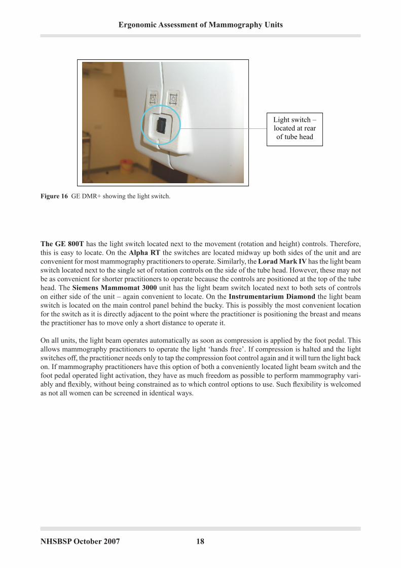
There are clear design differences with regards to the location of the switch across the units examined. On the GE dMR+ the switch is located at the rear of the tube head, making it awkward for mammography practition-ers to locate and use when positioning the woman (Figure 16).‘Cone’ buttons are located at the sides of the unit; these are used to vary the area over which the radiation falls on the bucky. The ‘cone’ buttons are used infrequently, however, and it would seem more appropriate to locate the more frequently used light beam switch in this more accessible location.
Ergonomic Assessment of Mammography Units
NHSBSP October 2007 �8
1
Figure 16. GE DMR + light switch
Light switch –
located at rear
of tube head
Figure �� GE DmR+ showing the light switch.
The GE 800T has the light switch located next to the movement (rotation and height) controls. Therefore, this is easy to locate. On the Alpha RT the switches are located midway up both sides of the unit and are convenient for most mammography practitioners to operate. Similarly, the Lorad Mark IV has the light beam switch located next to the single set of rotation controls on the side of the tube head. However, these may not be as convenient for shorter practitioners to operate because the controls are positioned at the top of the tube head. The Siemens Mammomat �000 unit has the light beam switch located next to both sets of controls on either side of the unit – again convenient to locate. On the Instrumentarium diamond the light beam switch is located on the main control panel behind the bucky. This is possibly the most convenient location for the switch as it is directly adjacent to the point where the practitioner is positioning the breast and means the practitioner has to move only a short distance to operate it.
On all units, the light beam operates automatically as soon as compression is applied by the foot pedal. This allows mammography practitioners to operate the light ‘hands free’. if compression is halted and the light switches off, the practitioner needs only to tap the compression foot control again and it will turn the light back on. if mammography practitioners have this option of both a conveniently located light beam switch and the foot pedal operated light activation, they have as much freedom as possible to perform mammography vari-ably and flexibly, without being constrained as to which control options to use. Such flexibility is welcomed as not all women can be screened in identical ways.

NHSBSP October 2007 ��
Ergonomic Assessment of Mammography Units
2.1.4 Exposure button
If a push button is used to operate the exposure it should be located centrally so either hand can operate it. This is a repetitively performed operation, a better design would possibly be a control which could be operated by the whole palm – thus distributing the force more widely and making it less focused on particular fingers.
The Lorad Mark IV and the Siemens Mammomat �000 have two exposure buttons that must be pressed in unison for the unit to take an image (Figure 17 and 18). The buttons are positioned on either side of the control panel (which is situated to encourage mammography practitioners to stand directly behind the protective lead glass screen) and are, therefore, operated with both hands. The design of the buttons is such that practitioners generally use their fingers to operate them because the buttons do not really protrude far enough from the panel to allow them to be pressed by the palms, which would distribute the pressure more widely.
Two exposure control
buttons. Requires two
handed operation and
can be operated
naturally with any
finger, not necessarily
thumbs
Exposure control
buttons – both must be
pressed in unison
Figure �7 Siemens mammomat 3000 showing synchronous exposure buttons.
Figure �8 Lorad mark iV showing synchronous exposure buttons.

Ergonomic Assessment of Mammography Units
NHSBSP October 2007 20
The GE dMR+ and the GE 800T also have two button operation; however, these buttons are placed directly beside one another. mammography practitioners can use either two hands to operate these or just one (Figure 19 and 20). Figures 19 and 20 actually demonstrate a unit which has had a secondary exposure control that has been retro-fitted.
Exposure button
on handle
Operation by two
finger exposure
button
Optional exposure
button control has
been retro-fitted but
offers flexible
exposure button
operation if
interchanged with
the two finger
exposure button
Figure �� GE DmR+ showing the dual buttons in close proximity.
Figure 20 GE DMR+ showing the optional exposure button fitted.

NHSBSP October 2007 2�
Ergonomic Assessment of Mammography Units
This is much like the Alpha RT exposure control. The design requires that the fingers are used to depress the controls. The Alpha RT has a thumb operated, grip hold exposure control (Figure 21). The mammography practitioner has to hold the control and extend the thumb over the top to depress the button – much like a computer joystick. if this control is located conveniently, practitioners do not have to lift the stalk; instead, they simply press the exposure button on the top. This allows variable use by any finger and takes the emphasis away from operation by the thumb.
The Instrumentarium diamond has a single exposure button (the one viewed was wall mounted); the fingers are used to operate this (Figures 22 and 23).
Exposure control
button – principally
operated by
depressing with the
thumb
Exposure control
button (wall
mounted control
unit)
Figure 2� Alpha RT showing the exposure control button.
Figure 22 instrumentarium Diamond showing the single exposure button.

Ergonomic Assessment of Mammography Units
NHSBSP October 2007 22
None of the units observed had a palm operated exposure button. The Siemens Mammomat �000 and the Lorad Mark IV give the greatest potential for mammography practitioners to operate the exposure control variably by changing the finger they use to operate the exposure. This limits the repetition with which a single finger operates the control.
2.1.5 Application of final compression
The compression plate must be power driven in both directions of travel over the complete range of movement.
All units have power driven compression, controlled by foot pedals. The units also have a dial which can be manually rotated to apply slight increments to compression/final compression. Mammography practitioners have complained that the Instrumentarium Alpha RT and the GE 800T do not have entirely smooth or responsive compression. The Alpha RT was described as having ‘jerky’ compression. Practitioners found it difficult to make slight adjustments. It is important that compression is responsive when making these fine adjustments because it allows the practitioner to meet the final compression ‘target’ quickly and easily. Non-responsive compression requires the practitioner to make subsequent readjustments; this potentially places strain on the feet and ankles when using the compression foot pedal and also slows down the screening proc-ess. On the GE 800T, the non-responsive compression is believed to be caused by a poor fitting compression paddle, which was not stable during the application of final compression.
The use of the manual dial should be limited as this requires the practitioner to pronate–supinate the wrist when twisting; this places more strain on the musculoskeletal structures of the wrist.
Several of the units feature an automatic compression release system in which the unit immediately releases compression after the image has been taken. This reduces the need for the mammography practitioner to worry about releasing compression after the exposure and is also more comfortable for the woman being imaged as compression ceases as soon as possible.
Operating the wall
mounted exposure
control button –
extended thumb and
deviated wrist
Figure 2� instrumentarium Diamond showing the extended thumb and wrist.

NHSBSP October 2007 2�
Ergonomic Assessment of Mammography Units
The Instrumentarium diamond also incorporates an ECS (Easy Compression System) facility (Figure 15). The mammography practitioner presses the ECS pedal on the foot controls and this moves the bucky upwards slightly to meet the compression paddle as it lowers. This serves to bring the breast over the bucky more effectively, positioning it more positively and reducing the extent of hand and wrist activity required during positioning. A similar feature, the EPS (Ekland Positioning Systen) pedal, is present on the Alpha RT (Figure 24).
The paddle depth on the GE 800T is considered to be too shallow. This protrudes into the chest wall of the woman during compression, making the experience far more painful. mammography practitioners have also described situations in which the breast that is not being imaged (the non-compressed breast) encroaches over the shallow lip of the paddle, obscuring the image which is being taken of the other, compressed breast.
Compact foot pedals;
however, they
incorporate only
vertical lowering of
the C-arm, not raising
it
Figure 2� Alpha RT showing the EPS pedal.
2.1.6 Pedals
These should be as low as possible and angled slightly to prevent over-flexion and extension of the ankle during operation. The pedal surface should be large enough to ensure that the foot can apply force effectively, but not so large that the pedal becomes a tripping hazard. It should have an area where the radiographer can rest her foot without having to remove her foot from the pedal. Pedals should not be too heavy or cumbersome so they can be easily repositioned by foot around the mammography unit. The lead connecting the pedals to the unit should be of an appropriate length that allows the radiographer to position them to suit her body size and eliminates excessive stretching to operate.
The design of the foot pedals differs radically from one unit to the next. The GE 800T has a small set of pedals. These are low set, lightweight and small, which limits ankle flexion during operation and makes them easy to reposition around the unit. These pedals control only compression, not vertical movement of the tube head. There is a raised lip separating the compression application and release pedals that can act as a foot rest.

Ergonomic Assessment of Mammography Units
NHSBSP October 2007 2�
Newer models of the GE dMR+ have more cumbersome foot pedals (Figure 25). However, these pedals also control vertical height adjustment of the tube head. This extra set of controls on the foot pedals often requires mammography practitioners to visually locate the exact pedal function they require. Not all practitioners appreciate or utilise the vertical control adjustment pedals. However, this does reduce the need to continually use the hand controls to adjust vertical column height. The fact that mammography practitioners are given the option of hand and foot controls means that they can choose and, more importantly, vary how they use the machine, and they can use this flexibility to suit the individual they are screening. Any design feature which encourages different methods of operation, and therefore allows the user to limit the extent of repetitive control actions, should be encouraged.
Foot pedals – control
compression and
vertical height
adjustment of the tube
head
Foot pedals
controlling
compression and C-
arm vertical height
adjustment
Figure 2� GE DmR+ showing the foot pedals.
The Lorad Mark IV has compression and vertical tube head height controls. The pedals are not considered cumbersome and are set low to the floor; there is also a rest area for the foot (Figure 26).
Figure 2� Lorad mark iV showing the foot pedals.

NHSBSP October 2007 2�
Ergonomic Assessment of Mammography Units
The Siemens Mammomat �000 has no vertical height adjustment control. The pedals are raised from the floor so that the mammography practitioner has to flex the foot slightly to operate them (Figure 27). There is a raised flat platform which separates the pedals and acts as a rest point for the foot.
Small size of
foot pedal
Figure 27 Siemens mammomat 3000 showing the foot pedals.
The Instrumentarium Alpha RT also has compact foot pedals (Figure 24). There are four controls: com-pression application and release, EPS and vertical tube head lowering (not raising). All controls are close to one another, which means the mammography practitioner does not have to deviate the ankle far to the side in order to operate a particular control. However, there is no rest area, and when practitioners wish to operate the pedal on the far side of the pedal unit they have to raise their ankle from the floor and extend their foot over the control.
The Instrumentarium diamond has a very flat set of foot controls that require minimum flexion of the ankle to operate (Figure 15). The pedal control itself is large, housing six functions (compression application and release, vertical lowering and raising, ECS and the automatic rotation control). These are spaced such that the mammography practitioner must actively move the foot between the controls, essentially deviating the foot, as the controls are spread over a large area. There are adequate rest areas on the foot control, and as such the potential for accidental operation of neighbouring foot pedals is limited. As may be expected, however, this is one of the most cumbersome controls to reposition around the unit.
One mammography practitioner suggested that if the controls were laid out in a mirror image they may be simpler to use. For example, the top grid (see below) shows a mirror image arrangement of the two sets of pedals positioned on either side of the unit (the black box in the centre represents the mammography unit); pedals closest to the unit are identical in function and this pattern continues across the four different controls on either side of the mammography unit. The possible argument is that practitioners can orient themselves better with this arrangement when they transfer around the woman being imaged and around the unit itself. The second grid shows how pedals are arranged at present across all equipment reviewed. NOTE that this is not a recommendation – simply a report of one individual’s opinion.
Compression
on
Compression
offRaise Lower Lower Raise
Compression
off
Compression
on
Compression
on
Compression
off Raise Lower
Compression
on
Compression
off Raise Lower
Suggested layout (top) and current layout (bottom).

Ergonomic Assessment of Mammography Units
NHSBSP October 2007 2�
2.1.7 Unit handles
Handles should be rounded so the corners do not ‘dig’ into the hands when gripped. They should be textured with material that does not feel cold to the touch (ie non-metallic) and is not slippery when gripped. The location of the handles should not restrict the radiographer’s access to the woman during positioning and they should run the length of the C-arm (past the pivot point). This enables all sizes of radiographer to easily reach them above or below the pivot such that they gain a mechanical advantage when rotating the C-arm. Handles should be colour coded to distinguish the handles to be held by the radiographer from those to be held by the woman. This makes it easier for the radiographer to instruct the woman to hold a certain handle.
All units that are manually rotated into position have adequate handles which run the entire length (vertically) of the mammography unit. This provides both tall and short mammography practitioners with adequate lever-age when rotating the unit. The motorised units, ie the Siemens Mammomat �000, Lorad Mark IV and the Instrumentarium diamond, do not require handles like this as they move into position without any force-ful exertion by the practitioner. All handles are smooth and non-metallic and are coated in non-slip material.
On the Instrumentarium Alpha RT there is a second handle running horizontally across the top of the tube head (Figure 28). Although this provides mammography practitioners with a further point of leverage when moving the unit into position, the handle protrudes several inches on either side of the tube head. When taking the oblique views, this reduces even further the space around the tube head (ie when the practitioner has to position the breast by bending under the tube head, which is rotated 45°). if the handle running vertically along the rear of the unit (Figure 6) was extended further (to the top of the tube head), it would provide similar leverage to the horizontal handle. This would enable the horizontal handle to be removed and would provide more space around the unit. mammography practitioners would then simply use the sole vertical handle, as they are required to do on the other units which are rotated manually.
Close up of
lateral handle
Figure 28 instrumentarium Alpha RT showing the lateral handle.

NHSBSP October 2007 27
Ergonomic Assessment of Mammography Units
2.1.8 Inserting and removing the film cassette from the breast support table
When inserting and removing the film cassette to/from the breast support table the radiographers often extended their thumbs or fingers while applying pressure to the cassette or button to release it. Force was also applied and the wrist was deviated. This problem could possibly be alleviated by rollers which feed the cassette in and out of the breast support table. However, this may take longer to perform.
All units feature two handed cassette release with a slide mechanism at the side of the bucky. To release the cassette, mammography practitioners have to slide the catch at the side of the bucky (this is generally done with the thumbs extended; Figure 29); they then have to reach over the bucky with the other hand and flex their fingers into the cassette loading recess to push out the cassette. Next, they pinch grip the cassette to remove it from the bucky. The Lorad Mark IV and some models of the Siemens Mammomat �000 automatically ‘eject’ the cassette once the slide catch at the side has been released, thus eliminating the need to push out the cassette manually.
This sliding release mechanism increases the strain on the thumbs and fingers during the screening process. The same release mechanism has been in use since the 1997 report, and it was highlighted then how potentially harmful this design was. Thumb pain is one area highlighted by mammography practitioners, and equipment needs to be designed that reduces forceful use of the thumb during the screening process.
The Instrumentarium diamond has an automatic loading facility, in which the loaded cassette is drawn into its final position mechanically. However, the cassette must still be removed as explained above. There needs to be more ergonomic design incorporated into the development of the loading–unloading systems.
1.1.1
Cassette
release
mechanism
Figure 2� instrumentarium Diamond cassette showing the release mechanism.

Ergonomic Assessment of Mammography Units
NHSBSP October 2007 28
2.1.9 Rotation guideline and compression displays
The rotation guideline should be located so that the radiographer does not have to twist to visualise it. The guideline should always be visible from the position the radiographer adopts during positioning of the woman. It should not be obscured by any parts of the unit.
All digital displays should be easily visible in the lighting conditions of the room.
When performing the medio-lateral view the angle of 45° forms the basis from which all minor adjustments are made. This angle should be clearly distinguishable from all other markings on the scale.
The layout and location of these displays vary greatly across all units. Not all are in positions that are easy to visualise, and it appears that not all manufacturers have accepted the need to design displays that can be viewed easily by all sizes of mammography practitioner, no matter their orientation around the mammography unit.
The Lorad Mark IV has a compression display which is located several inches above the height of the bucky (attached to the compression paddle) and is angled upwards (Figure 30). This makes it difficult for shorter mammography practitioners to visualise the display when preparing for the craniocaudal (CC) view (par-ticularly when the woman being imaged is tall). There are two rotation guideline displays that are positioned behind the C-arm (one on either side of the tube head). However, these can be obscured by the C-arm when the unit is rotated to certain angles. it is unacceptable that mammography practitioners have to bend and twist around the C-arm to view the angle of rotation when it is this information that they require to rotate the arm to its endpoint.
Compression force
and breast thickness
display
Figure �0 Lorad mark iV showing the compression display.
NHSBSP October 2007 2�
Ergonomic Assessment of Mammography Units
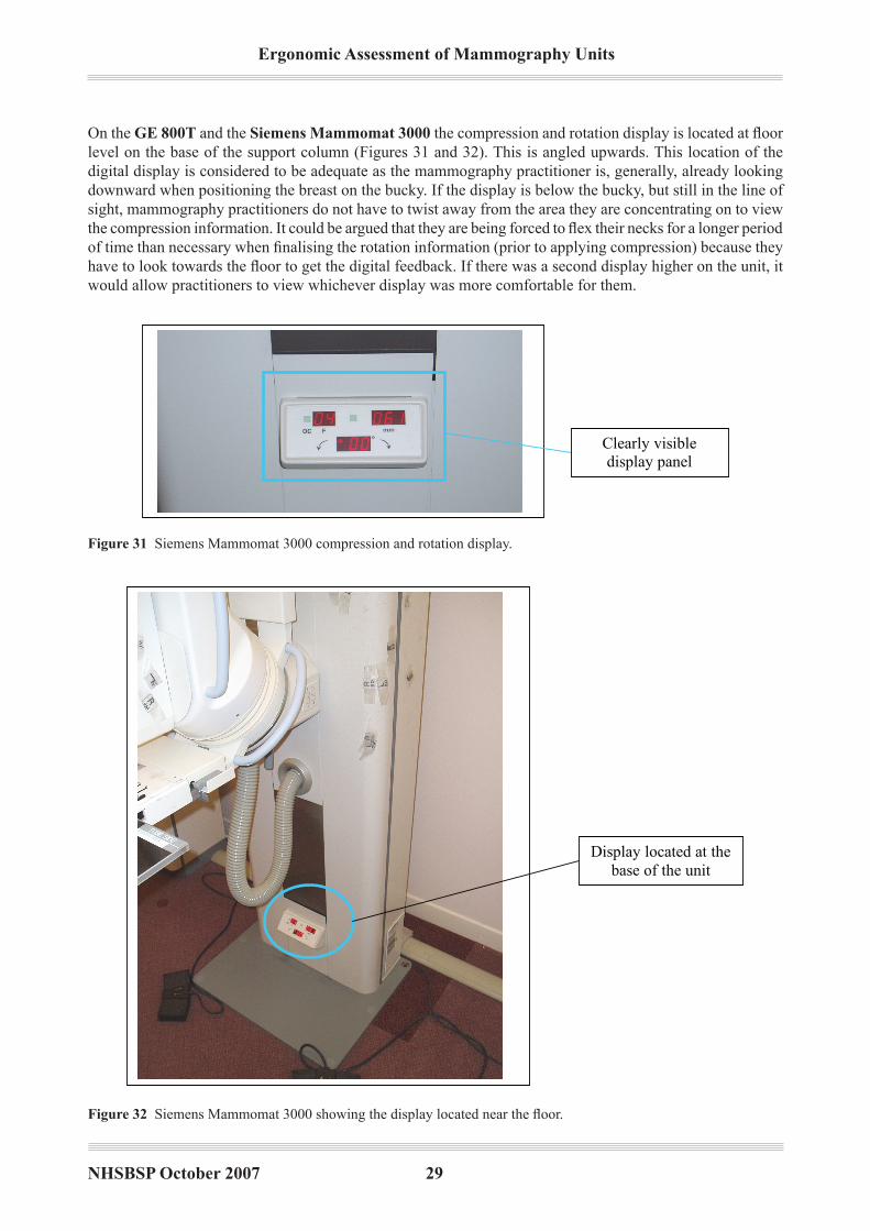
On the GE 800T and the Siemens Mammomat �000 the compression and rotation display is located at floor level on the base of the support column (Figures 31 and 32). This is angled upwards. This location of the digital display is considered to be adequate as the mammography practitioner is, generally, already looking downward when positioning the breast on the bucky. if the display is below the bucky, but still in the line of sight, mammography practitioners do not have to twist away from the area they are concentrating on to view the compression information. It could be argued that they are being forced to flex their necks for a longer period of time than necessary when finalising the rotation information (prior to applying compression) because they have to look towards the floor to get the digital feedback. If there was a second display higher on the unit, it would allow practitioners to view whichever display was more comfortable for them.
Clearly visible
display panel
readout
Display located at the
base of the unit
Figure �� Siemens mammomat 3000 compression and rotation display.
Figure �2 Siemens Mammomat 3000 showing the display located near the floor.

Ergonomic Assessment of Mammography Units
NHSBSP October 2007 �0
The GE dMR+ has the display mounted on the support column behind the tube head (Figures 33 and 34). mammography practitioners have to look away from the bucky to read the compression and rotation informa-tion. As this display is directly behind the tube head, it can be obscured when the unit is rotated to the oblique angles. However, the display is set back from the C-arm and is large and thus can be easily located. One criti-cism of this display is that it does not continually show the compression force information. moments after compression is halted, the data are cleared from the screen; practitioners must acknowledge the compression force immediately as they are unable to refer back to it. Feedback from the rotation display is not instantane-ous, and there is a momentary delay between movement of the C-arm and a readout appearing. This makes it difficult for practitioners to settle the unit instantly at the desired angle and they often have to make slight adjustments to move the unit appropriately. The rotation information is also ‘wiped’ from the screen upon initiation of compression in order to make way for the compression information (as shown in Figures 33 and 34). The dot-matrix display is also considered cluttered and difficult to read.
Display showing
compression
information. The
display is located
on the support
column behind
the C-arm
During rotation, the
display shows only
rotation angle
information. This
information disappears
once rotation is halted,
making way for the
compression
information that is
shown on the same
display
Figure �� GE DmR+ display showing the compression readout.
Figure �� GE DmR+ display showing the rotation angle.

NHSBSP October 2007 ��
Ergonomic Assessment of Mammography Units
The display location on the Instrumentarium Alpha RT is poor (Figure 35). it is positioned above the compression paddle under the tube head. When performing the CC views, taller mammography practitioners often have to bend and twist to see the display as it is occluded by the tube head. When performing the mLO views, both tall and short mammography practitioners must bend and twist to see the display as it is angled away from the direct line of sight. in many instances, the practitioner is actually bending below the tube head with her head level with, or even below, the display. The location of the display makes it difficult to see from this position. However, once visible, the display is clear to read and not cluttered.
Display view when
unit rotated to 45
degrees. This
location has been
reported as being
difficult to view by
many radiographers
Clearly visible
display positioned
behind the
compression paddle
Figure �� instrumentarium Alpha RT showing the display view when at 45°.
On the Instrumentarium diamond the compression and rotation display is located on the control panel (behind the bucky). This is directly next to the area where the mammography practitioner is positioning the breast. it therefore requires no bending and twisting away from the area where the mammography practitioner is positioning in order to obtain any readout information (Figures 36 and 37). The display is also angled upwards very slightly, in such a way that it is easy to visualise from all orientations around the unit.
Figure �� instrumentarium Diamond compression and rotation display.

Ergonomic Assessment of Mammography Units
NHSBSP October 2007 �2
2.1.10 Film marker location
The most frequently used film markers should be stored in a position where they can be located rapidly and within easy reach.
The Siemens Mammomat �000, the Instrumentarium Alpha RT and the Instrumentarium diamond all feature ‘slide down’ markers (Figures 38–40). These are a set of strips that are stored behind the bucky and slide over the face of the bucky when appropriate. They do not detach from the unit.
Display when unit
is rotated to 45
degrees
Figure �7 instrumentarium Diamond display view when at 45º.
Slide down
markers
Figure �8 Siemens mammomat 3000 showing ‘slide down’ markers.

NHSBSP October 2007 ��
Ergonomic Assessment of Mammography Units
The GE dMR+ has a cumbersome set of magnetic markers which are fixed to the rear of the bucky and twist down over the bucky (Figure 41). The markers are awkward to move and are frequently pulled off when twisted into position. Some versions of the GE 800T and the Lorad Mark IV have ‘rubber suction’ markers. Their holder is not attached to the unit and they are generally stored away from the bucky. These frequently fall off the bucky when it is rotated as the suction is not adequate. mammography practitioners have been observed to adapt the markers by attaching tape to them to stick to the bucky. As they are not conveniently located near the bucky, practitioners frequently carry their own markers in their pockets as this is more convenient and faster for them to use.
Slide down
film markers
Figure 40
Slide down
markers. Can be
removed if
extreme
compression is
necessary
Figure �� Alpha RT showing ‘slide down’ film markers.
Figure �0 Instrumentarium Diamond showing ‘slide down’ film markers.

Ergonomic Assessment of Mammography Units
NHSBSP October 2007 ��
2.1.11 Compression paddle
The surface of the compression paddle should be coated with a non-reflective surface to reduce the likelihood of glare which interferes with the radiographer’s vision when positioning the breast.
The range of movement of the compression plate must be from 1 cm from the breast support table to not less than 18 cm from the table. This allows the radiographer better access to the breast.
Mammography practitioners still complain of glare; however, manufacturing a non-glare surface is difficult as the paddle must be transparent to enable radiographers to perceive the breast. All units exhibited glare from the paddle to some extent.
2.1.12 Weight of the tube head
The tube head should be as light as possible and the possibility of providing a motor or power driven C-arm should be investigated. The force used to rotate the C-arm should not exceed 30 N.
The non-motorised mammography units were the Instrumentarium Alpha RT, the GE dMR+ and the GE 800T. The Alpha RT is considered to be light to move and the handles are adequate to provide leverage to move the unit into position. The GE 800T is considered to be cumbersome and heavy to move.
Figure �� GE DmR+ showing magnetic markers.
Twist down
magnetic
markers

NHSBSP October 2007 ��
Ergonomic Assessment of Mammography Units
2.2 Additional observations
2.2.1 Isocentric movement
The Siemens Mammomat �000 and the Lorad Mark IV feature isocentric rotation. When the unit is rotated, the bucky does not rise or drop, but remains at the same height as the previous projection. This feature means that mammography practitioners are not required to readjust the bucky height between projections. in some instances, this will be unavoidable if it is difficult to position the woman; however, isocentric rotation means that any height readjustments are minimal.
2.2.2 Changing the bucky
The Siemens Mammomat �000 has a ‘fly wing’ swivelling bucky feature (Figure 42). Mammography practi-tioners do not need to physically remove one size of bucky from the unit to fit the other. Instead, they operate a lever and the alternative bucky swivels round from behind the C-arm into position, whereas the bucky that was being used swings back behind the C-arm. All other units require the practitioner to remove one bucky from the unit and attach the other. This can be awkward, requiring force to pull the bucky free from the unit and push the other one into place.
Flywheel bucky simply
twists round to allow
mammography
practitioner to shift
between 18 × 24 and
24 × 30 bucky (this unit
does not feature the
24 × 30 bucky – but it
would be fitted here)
Figure �2 Siemens mammomat 3000 swivelling bucky.

Ergonomic Assessment of Mammography Units
NHSBSP October 2007 ��
2.2.3 AEC chamber selection
The AEC chamber selection control varies across the units. The Lorad Mark IV and the Instrumentarium Alpha RT have a rod which protrudes from beneath the bucky (Figures 43 and 44). This is gripped with a fist grip and neutral wrist posture. The fingers and thumbs are not used and the force is spread over this larger muscle group. However, because they are positioned beneath the bucky, the alternative chambers are not easy to see, and mammography practitioners rely on tactile feedback as the selector passes through each chamber making a noticeable ‘judder’ or ‘click’. A beneficial feature of the Lorad Mark IV is that the selected chamber is clearly displayed next to the compression display (Figure 45) The Alpha RT is described as ‘jerky’ to move into position; however, it does offer the option of lateral chambers which allow mammography practitioners to take better quality images.
AEC selector handle
beneath the bucky
AEC selector handle.
It is positioned under
the bucky and
operated by pushing
away and pulling
towards the body
Selector
Figure �� Lorad mark iV showing the rod type chamber selector.
Figure �� instrumentarium Alpha RT showing the rod type chamber selector.

NHSBSP October 2007 �7
Ergonomic Assessment of Mammography Units
The GE 800T, GE dMR+ and the GE dMR incorporate a recessed slide selector at the side of the bucky (Figure 46). This is generally operated with the thumbs or a pinch grip. The chambers are clearly marked and there is adequate tactile feedback to indicate that a chamber has been selected. However, relying on the fingers to operate this selector is likely to put further strain on this weaker muscle group as the selector can be stiff to operate.
AEC display, clearly
showing which
chamber has been
selected
Figure �� Lorad mark iV showing the chamber selection indicator.
AEC selector
switch
Figure �� GE DmR+ showing the recessed slide selector.

Ergonomic Assessment of Mammography Units
NHSBSP October 2007 �8
The Siemens Mammomat �000 selector is a lever which is positioned to the side underneath the bucky (Figure 47). it must be slid into place by either the thumb or a pinch grip. The selector is stiff to move and offers little tactile feedback to indicate which chamber has been selected. As a result, mammography practitioners often have to bend to the height of the selector to determine its actual position.
AEC selector
positioned at the side
of the bucky –
requires forceful
thumb/pinch grip
operation
Forward/backward slider
Eight AEC
selector buttons
where manual
selection of the
chamber is
necessary
Figure �7 Siemens mammomat 3000 showing the AEC lever selector.
The Instrumentarium diamond offers automatic exposure control, relieving mammography practitioners of this task. However, in some instances, this must be done manually. The appropriate chamber is selected by choosing one of the options on the control panel, which consists of eight buttons representing different areas of the bucky (the panel is located behind the bucky) (Figure 48). The membrane pad buttons are easy to operate and clear to use.
Figure �8 instrumentarium Diamond showing the chamber selection panel.

NHSBSP October 2007 ��
Ergonomic Assessment of Mammography Units
2.2.4 Vertical height adjustment
The GE dMR+ does not drop to a low enough height to accommodate wheelchair users. The Lorad Mark IV offers limited legroom beneath the bucky for wheelchair users.
2.2.5 Bucky design
The depth of the bucky has been reported as a problem. it has been reported that units with a deep bucky make it more difficult to position larger women as the bucky has to fit between the breast and the abdomen. Both the GE 800T and the GE dMR+ have been described as having a deeper bucky, which causes problems for mammography practitioners when screening larger women (Figure 49). The Siemens Mammomat �000 has a narrow bucky depth in comparison (Figure 50).
DMR bucky – side
view
Narrow bucky
depth
Figure �� GE DmR+ showing the bucky.
Figure �0 Siemens mammomat 3000 showing the bucky.

Ergonomic Assessment of Mammography Units
NHSBSP October 2007 �0

NHSBSP October 2007 ��
Ergonomic Assessment of Mammography Units
�. ANALYSIS OF THE CURRENT BREAST SCREENING TASK
�.� Current study
The previous chapter described the assessment of mammography units in current use against the recommen-dations of the 1997 report. However, there are a range of aspects of breast screening that have changed since 1997, particularly in reference to modern mammography units and their compliance with the recommenda-tions of the 1997 report.
To understand the current situation and to put the 1997 report in its proper, modern context, it is necessary to investigate the wider situation within which mammography units are now operated and to note any key changes which have occurred that are associated with the mammographic tasks themselves. in particular, this study aims to combat work related injury; hence, particular emphasis has been placed on the investigation of the physical demands of conducting mammography and the potential risk for musculoskeletal disorders.
The work was carried out on a small sample of equipment and mammography practitioners, and aimed to update the knowledge contained in the previous report based on current practices rather than to recreate it from first principles. With the expectation that digital mammography will increasingly be used for mammographic screening, and the subsequent importance of understanding the ergonomic implications of this equipment, two digital units were included in the study. it should be noted, however, that owing to their current scarcity within the screening programme it was not possible to observe these digital units within a screening environment.
3.1.1 Data collection
Two mammography centres were visited. in total, eight mammography practitioners performing mammograms were interviewed and observed during their working day. At each centre, observations were also made of the way that x-ray films were mounted onto multiviewers. Table 1 details the units that were observed in opera-tion; these were felt to cover a range of features typically experienced with such units.
Table � Units observed
Analogue units digital units
Lorad mark iV (three units) Fischer imaging SenoScan (one unit)
Siemens mammomat 3000 Nova (one unit) GE Senographe 2000DS (one unit)
3.1.2 Potential limitations to the study
it should be noted that the conclusions of this assessment are based on observation of a small sample of mam-mography practitioners. Only stressors related directly to conducting mammography were examined, but there may be other broader contributing factors outside the work situation that may also play an important role in terms of psychosocial issues and stress.
For ethical reasons, it was not possible to take photographs or video recordings of the tasks when they were being conducted with women attending for screening. instead, the photographs used in this report feature mammography practitioners demonstrating the task, with other work colleagues taking the position of the woman being radiographed.

Ergonomic Assessment of Mammography Units
NHSBSP October 2007 �2
�.2 Background information
3.2.1 Mammography units
Digital units are currently under evaluation for routine use in the NHSBSP; therefore, their use is somewhat limited. Care must be exercised when attempting to compare certain aspects, such as repetitive musculoskeletal effects, with analogue units reviewed in a more hectic screening situation.
Analogue units are used widely as part of the NHSBSP. These units can be permanently located within a centre or situated in a mobile unit that can be transported to different regions. mobile units present a slightly differ-ent situation as they are used in more confined spaces and at a higher rate with shorter cycle times. However, mobile units are not considered in this report. The focus of this study is on units used in permanent locations within screening centres.
Some 4–5 years ago, lottery funding was available to buy new units, and most hospitals trusts bought the analogue units current at this time. These units will be replaced in the next couple of years and replacement units are likely to be digital. it is anticipated that the use of digital systems will increase and become more widely introduced into the NHSBSP.
3.2.2 Work routines of mammographers
Typically in mammography screening centres, each mammography practitioner will see and x-ray 20 clients each day, with five minutes being allotted to each client. After each x-ray session with a client, it takes approxi-mately 4–5 minutes to process and label each client’s set of radiograph films.
Symptomatic clinics work at a slower pace than breast screening clinics.
3.2.3 X-ray film cassettes
There are two sizes of x-ray film taken (resulting in two sizes of film cassettes for analogue machines): 18 × 24 cm and 24 × 30 cm. The different sizes relate to the size of breast being imaged:
80% of clients have small breasts (use of 18 × 24 cm cassettes)20% of clients have large breasts (use of 24 × 30 cm cassettes)
Some centres use only the smaller size of film cassette (18 × 24 cm). In these centres, when a client has large breasts, two x-ray films from the same view will be exposed to provide two separate partial images of the breast. These are taken with sufficient overlap such that no areas of the breast are omitted. The two x-ray films will then be mounted next to each other to present one complete image of the breast. This results in a client with large breasts potentially having eight x-ray films in one session, which increases workload. Limiting a unit to one size of film cassette also has an impact on the workload for the mammography practitioner taking the mammograms and for the person mounting the films.
••

NHSBSP October 2007 ��
Ergonomic Assessment of Mammography Units
3.2.4 Breast weight
Large breasts are heavy and difficult to position. The number of women with large and heavy breasts is increasing, particularly with increasing use of hormone replacement therapy (HRT). HRT can have the effect of maintaining heavier material in the breast later into life. Additionally, the average age of the population (and therefore of screening clients) is also increasing, and older women often have larger breasts.
3.2.5 Reported problems
Mammography practitioners reported that it is difficult to think about the postures that they adopt while working because their priority is the client and getting the job done. Furthermore, it was reported that it is difficult for mammography practitioners to visualise what postures they are adopting. mammographers commented that, as they are mainly working on their own, they do not often observe other mammographers and certainly never observe themselves. This makes it difficult to see the types of postures that are adopted while conducting the task. Consequently, it was stated by several mammography practitioners that it is very easy to get stuck in a particular routine or method of working, which may work well in carrying out the task but which may not be the most effective in terms of controlling the risk of poor posture.
For instance, one short stature mammography practitioner reported experiencing elbow pain. She stated that it was work related but she was unsure as to the exact cause. Several taller mammography practitioners reported experiencing knee pain, which they attributed to awkward bending to view the breast and reaching foot controls when conducting radiographs, particularly of the mediolateral view.
All mammography practitioners reported that large breasts are heavy and difficult to position and often resulted in thumb and wrist discomfort due to the additional effort required.
Locking and unlocking doors to and from the radiography room was reported as necessitating additional hand and wrist effort because of the twisting action, which was described as being tiring. Also, it may be that doors need to be heavy and secure, but where they are a regular obstacle to the task it is clear that there is scope for improvement.
3.2.6 Overview of the mammography task
Four distinct tasks have been identified as being integral to mammography. These are:
Task 1 – taking the mammogramsTask 2 – processing the x-ray filmsTask 3 – mounting the processed filmsTask 4 – reading the mammograms.
This report focuses on the first three tasks, as task 4 is outside the remit of the work. Tables 2–5 present an overview of the tasks and the subtasks that occur within each of these processes, for each type of unit (ana-logue and digital).

Ergonomic Assessment of Mammography Units
NHSBSP October 2007 ��
Table 2 Task elements of taking mammograms
Task element Analogue digital
Collect notes and film cassettes ✓ ✗
Show client into the x-ray room ✓ ✓
Check client’s details; complete form/data entry via computer
✓ ✓
Client undresses ✓ ✓
Take mammograms ✓ ✓
Craniocaudal view (right breast)Craniocaudal view (left breast)mediolateral view (left breast)mediolateral view (right breast)
Assess whether support table is correct size ✓ ✗
Label support table ✓ ✗
Adjust breast support table position ✓ ✓
Place breast on support table ✓ ✓
Position breast and apply compression ✓ ✓
Take mammogram (activate radiation) ✓ ✓
Release compression ✓ ✓
Check image of sufficient quality and full image, no artefacts
✗ ✓
Remove cassette ✓ ✗
Name cassette ✓ ✗
Check all digitised images and send ✗ ✓
Client gets dressed ✓ ✓
Return client to waiting room ✓ ✓
Clean unit ✓ ✓
Carry completed cassettes out for processing
✓ ✗
Table � Task elements of processing x-ray films
Task element Analogue digital
Process x-ray film Load completed film cassette into processor ✓ ✗
Retrieve empty film cassette from processor ✓ ✗
Place empty cassette onto empty cassette pile ✓ ✗
Retrieve processed films from the processor
✓ ✗
Mount films on viewer and check for full image, artefacts, etc.
✓ ✗
Stick appropriate identity label onto each film
✓ ✗
File films ✓ ✗

NHSBSP October 2007 ��
Ergonomic Assessment of Mammography Units
�.� Postural assessment
The operations conducted by the mammography practitioner on analogue and digital units were examined in relation to the key risks of work related limb disorders: force, posture, repetition and duration. The assessment of mammography practitioners conducting mammography was based on:
observations of each mammography practitioner adopting typical working postures on analogue units and digital unitsfrequency and duration of task cycle times.
The assessment procedure was conducted based on static and limited dynamic observation made during each visit. it therefore provides only an indication of the type of problems caused by poor and awkward postures that are likely to increase the risk of musculoskeletal disorders.
For the purposes of postural assessment of the tasks involved, a detailed breakdown of the mammography task into its subtask elements was first conducted. Physical actions required in each task element were then assessed. This highly detailed part of the work was carried out primarily for analogue mammography because this also covers the main posture related tasks involved in digital mammography. Digital mammography involves fewer task elements, and its associated procedures are not as well established nationally as they are for analogue mammography. Any postural implications found to be specific to digital mammography or the digital units investigated are detailed separately later.
The tables in Appendix 1 present in detail a full breakdown of the tasks associated with using mammographic units into their subelements and the physical actions required. The next section of this report discusses spe-cific elements of the mammography task that were identified as presenting medium to high levels of risk for musculoskeletal injury.
The task analysis charts in Appendix 2 may be used as a ‘map’ for placing the detailed task elements given in Appendix 1 within the wider mammographic process. The charts in Appendix 2 cover a wider breadth than the detailed tables in Appendix 1, including for comparison task analysis for analogue (charts 1 and 2), digital (charts 3 and 4) and ‘fully’ digital (chart 5) mammography. Additionally, these go beyond the tasks involved with the mammography unit and subsequent film processing to include tasks associated with mounting the processed films and/or images in preparation for screening. Appendix 2 and its task analyses are discussed in more detail in section 3.4.
•
•
Table � Task elements of mounting processed films onto a multiviewer
Task element Analogue digital
Sort out files for a client ✓ ✗
Retrieve the current file of x-ray films ✓ ✗
Retrieve previous file ✓ ✗
Mount each film onto the multiviewer
✓ ✗
Place the empty file in the appropriate empty file box
✓ ✗

Ergonomic Assessment of Mammography Units
NHSBSP October 2007 ��
3.3.1 Task elements of medium and high risk
The adoption of awkward postures, particularly at extreme ranges of motion, increases the risk of musculoskel-etal disorders. Awkward postures include any fixed or constrained position or any postures which overload muscles or tendons, load joints in an uneven or asymmetrical manner or involve static loading. Assuming and sustaining awkward postures can induce significant biomechanical stress on the musculoskeletal system. Prolonged postures or repetitive motions should be kept close to the body segment’s neutral position and preferably should be broken up with significant rest breaks or alternative positioning.
The tasks of positioning the breast, applying compression when taking the mediolateral view, manipulat-ing and orientating film cassettes and mounting radiographs onto the multiviewer through a combination of applied force and poor or awkward posture in association with the frequency with which these postures are adopted result in medium to high risk. Sections 3.3.2 to 3.3.5 discuss each of these task elements in detail. Furthermore, aspects in which significant differences were observed between postures adopted in the use of digital and analogue units are also discussed.
3.3.2 Positioning the breast
Level of risk: medium/high (particularly when taking the mediolateral view)High risk to: elbows, wrists and thumbs
Task descriptionThe mammography practitioner needs to view the breast to position it correctly on the support table and to ensure that the nipple is appropriately positioned and that there are no artefacts or skin folds. The practitioner applies force to hold the breast. This application of force is sustained until the breast is correctly positioned and slight compression is applied. This task can be repeated in succession four times in a single five minute session (this can increase to eight times depending on the size of breast and the availability of different sized cassettes; see section 3.2.3). This equates to conducting this task element approximately 80–160 times per day.
Physical actionsTo maintain a view of the breast, it is necessary for the mammography practitioner to frequently twist and extend her neck and also to bend at the trunk. Both of the mammography practitioner’s legs are bent and posi-tioned apart to lower her overall body position and to enable her to view the breast, which otherwise would be obscured by the head of the machine. This posture is more pronounced when taking images of the mediolateral view, and is even more pronounced for digital units than for analogue units (Figures 51 and 52).
For both the craniocaudal and mediolateral views (on both types of unit), the mammography practitioner often achieves the correct position of the breast through excessive extension of her arm at its maximum range of motion across the support table (see Figures 51 and 52). For the craniocaudal view, the mammography prac-titioner lifts up the breast in the palm of her hand in order to form a right angle with the woman’s body. This requires supination of the mammography practitioner’s forearm combined with radial deviation and extension of the wrist and also forces the thumb into hyperextension. For the mediolateral view, there are two different positioning techniques used.
Technique 1 The right hand thumb is fully extended and is used to support the weight of breast and to push the breast up to the correct position on the support table. Use of the thumb allows the forearm and wrist to stay in line. However, the thumb is used in a weak position (fully extended) to take the full weight of the breast. The use of the thumb in this posture with such a load places the thumb and wrist at risk of injury, particularly with the rate of repetition and duration that this posture is adopted.
••
•

NHSBSP October 2007 �7
Ergonomic Assessment of Mammography Units
Technique 2 The fingers are used to support and push the breast into position. This requires the elbow to be held outwards to rotate the forearm so that the palm of the hand is able to push up against the breast. This will lead to awkward rotation of the shoulder and elbow joints. The other hand (not holding the breast in position) is used to keep the shoulder, stomach and other breast from protruding into the field of view for imaging.
•
Figure �� Taking the mediolateral view using an analogue unit.
Figure �2 Taking the mediolateral view using a digital unit.

Ergonomic Assessment of Mammography Units
NHSBSP October 2007 �8
RisksViewing the breast Neck stress is often experienced with hand–eye coordinated tasks. The mammography practitioner’s view of the breast may be obscured by features of the mammography unit, and this may result in awkward extension and twisting of the mammography practitioner’s neck. in addition, maintaining a clear view of the breast causes the mammography practitioner to adopt an overall awkward posture, which is sus-tained throughout the task. When adopted frequently, there is risk to the neck, back and knees.
Supporting and positioning the breast The two techniques for holding the breast in position present risk either to the thumb and wrist or to the elbow. There is a risk of injury when the wrist is rotated into pronation or supination combined with ulnar or radial deviation while extended. This risk is significantly increased when combined with the application of force, eg supporting the weight of the breast. The larger and heavier the breast, the greater the risk. This risk is significantly greater when conducting the mediolateral view, as the application of force is sustained for a much longer duration. The mediolateral view requires the support table to be at an angle, which can cause the breast to slip and fall out of position; therefore, the mammography practitioner has to push and hold the breast in position for a longer duration, until some compression is applied.
in addition, positioning the breast requires the mammography practitioner to work with her arms above or just below shoulder height and with her arms outstretched. A simple reach triggers a complex action of the arm and hand. Muscles that originate in the forearm control the wrist and finger motions. Therefore, awkward wrist positions and forearm motions can cause pain at the elbow.
SummaryThis task action occurs interspersed with other significantly different tasks (in which the mammography prac-titioner uses other body parts in a significantly different way and with less force). Therefore, in the analogue process at the current rate of working, and with the built in less intense tasks such as film processing, the risk associated with this task element is currently rated as medium. However, if this task element were sustained for a prolonged period of time and/or repeated at a higher rate, it would result in high risk.
3.3.3 Applying compression: mediolateral view
Level of risk: medium/highHigh risk to: neck, back and knees
Task descriptionThe mammography practitioner uses her left or right foot to depress a foot pedal to activate compression. This is conducted while supporting and smoothing the breast to maintain its correct position on the support table. Once some compression has been applied (sufficient to hold the breast in place), the practitioner removes her hand and applies full compression. This requires the practitioner to maintain a view of the breast and to read the compression level display. The overall posture is sustained until the breast is correctly positioned and full compression is applied. This task can be repeated in succession 2–4 times (depending on the size of breast and the availability of different sized cassettes; see section 3.2.3) in a single five minute session.
Physical actionsCombined use of the foot pedal while keeping one hand on the breast (to maintain its correct position) often results in an asymmetrical posture for the mammography practitioner. When a mammography practitioner uses the foot pedal, it destabilises her posture; therefore, additional effort is required from the trunk and opposite leg to maintain an upright stance. in addition, the supporting leg remains bent with the trunk slightly stooped and the neck is kept extended and twisted to maintain a view of the breast and the compression display during
••

NHSBSP October 2007 ��
Ergonomic Assessment of Mammography Units
the application of final compression. This further increases the unequal distribution of weight placed on the supporting leg and twisted trunk.
Some mammography practitioners are starting to conduct this part of the task while seated. Once the breast has been positioned and some slight compression has been applied, the practitioner will pull the chair behind her to sit. She then proceeds to apply full compression. From limited observation, this appeared to reduce the degree of neck extension and to reduce the demands placed on the supporting leg. in addition, a slightly better, more upright, trunk posture could be maintained while applying full compression (Figures 53 and 54).
Figure �� Taking the mediolateral view using an analogue unit while seated.
Figure �� mammography practitioners taking the mediolateral view using a digital unit while seated.

Ergonomic Assessment of Mammography Units
NHSBSP October 2007 �0
However, issues of locating the seat and being able to sit down on it without it scooting off require considera-tion. The mammography practitioner typically sits down on the seat without turning round to check its exact location. Furthermore, practitioners were limited to one hand to hold the chair while they lowered themselves into it. The design of the seat used needs careful consideration because it is important that it provides good stability. it was observed that practitioners typically perch on the edge of the seat; this may increase the like-lihood of the seat moving out from under them. The presence of arm rests on the seat provides an important tactile cue to its position.
A saddle seat was present in one centre; however, this was of incorrect size for the majority of the mam-mography practitioners (it was too big) and it was also difficult to mount and dismount and was reported as causing more problems than it solved.
SummaryThis task action occurs interspersed with other significantly different tasks (in which the mammography practitioner uses other body parts in more neutral positions and in a significantly different way). Therefore, in the analogue process with the current format of working, the risk associated with this task element is rated as medium. However, if the actions of this task element were sustained for a prolonged period of time and/or repeated at a higher rate it would result in the task being high risk.
3.3.4 Inserting, removing and manipulating film cassettes
Level of risk: mediummedium risk to: wrists and thumbs
Task descriptionThe mammography practitioner picks up a new cassette and flips it so that the correct surface is facing upwards (labels facing downwards). Next, the mammography practitioner moves the switch to the side using either her thumb or the palm of her hand (Figure 55). The mammography practitioner then inserts the cassette into the slot. Once the exposure has been made, the practitioner removes the cassette from the support table by moving the switch with her thumb or palm and then reaching with her other arm round to push the cassette up and out from the bottom. The practitioner then flips the cassette over so that the labels face upwards (Figure 56) and places the cassette into the naming machine. This cycle is repeated after each view of the breast. This action is conducted 12 times in each five minute session.
Physical actionsThe mammography practitioner twists her wrist from supine to prone, and applies force with her thumb to move the switch when inputting or removing each cassette. This places some localised pressure and stress on the thumb.
••

NHSBSP October 2007 ��
Ergonomic Assessment of Mammography Units
Figure �� Switch to insert and remove film cassettes.
3.3.5 Mounting processed films on to the multiviewer
Level of risk: medium/highmedium risk to: shoulders and wrists
Task descriptionEach morning for approximately one hour, staff mount the previous day’s mammograms for each client onto multiviewers for readers to view and assess (Figure 57). This requires picking up files, separating each x-ray film and pushing these onto the light box of the multiviewer. The mulitviewer is positioned vertically in front of the mammography practitioner. If a client has been screened previously, her films from three years ago will also be mounted along with the new films for comparisons to be made. Therefore, each practitioner will mount approximately 80 sets of films. Typically, each set will comprise four films. In the course of one hour, an individual practitioner will mount approximately 320 films. This equates to one film mounted every 11.25 seconds. This task is conducted only for mammograms produced from an analogue machine.
Physical actionThe mammography practitioner must perform fine dexterous hand and finger movements with the wrists often in extension.
••
Figure �� Mammography practitioner removing film cassette from the breast support table.

Ergonomic Assessment of Mammography Units
NHSBSP October 2007 �2
RiskThe main risks associated with this task are the high rate of repetition and working with the arms held out unsupported for a prolonged period of time. As this task is conducted for an hour in the morning, the degree of risk depends on the other tasks that a practitioner performs after this task and whether they are similarly hand intensive. it was also noted that the workstations offered restricted leg room, which further constrained the practitioner’s posture.
�.� Task analysis
A task analysis was constructed for conducting the mammography task. This included: taking the mammo-grams, processing the images and mounting the processed films. The task analyses are shown in Appendix 2. Task analysis charts 1 and 2 present the task procedures when an analogue unit is used. Task analysis charts 3 and 4 present the task procedure for a digital unit after immediate introduction, and task analysis chart 5 presents the task procedure of processing film and mounting film when all previous cases are also digital images. On task analysis charts 3, 4 and 5, the task modules shaded in grey are previous tasks required in the use of analogue machines but which have been eliminated in the digital process, and task modules shaded in yellow are new tasks that occur only in the digital process.
Overall, the operation of a digital unit reduces the number of task elements conducted as part of the mam-mography task compared with an analogue unit (see Tables 2–5). in summary, the digital process eliminates the following task elements:
carrying and orientating film cassettesloading and unloading cassettes into the support tableloading and unloading cassettes into the naming machinethe need to change the support table and compression paddlethe need to adjust the position of the exposure chamberfilm processing – loading and unloading cassettes into the processorthe need to recall a client following an incomplete or blurred imagethe mounting of processed films.
The removal of these tasks will reduce the physical effort required per client, and could potentially reduce the overall risk presented by the whole task.
••••••••
Figure �7 X-ray films being mounted onto a multiviewer.

NHSBSP October 2007 ��
Ergonomic Assessment of Mammography Units
The digital units introduce a few new task components. These include:
inputting client details into the computer systemchecking that each image is of sufficient quality after each image exposurechecking (on screen) that all four complete images are taken and then sent or stored.
These new tasks are not physically demanding and present no additional risk.
However, the tasks of positioning the breast and taking radiographs in craniocaudal and mediolateral views remain primarily the same in the digital as in the analogue process, and it is these tasks which are classed as presenting the highest risk of musculoskeletal disorder. Furthermore, in some instances, it was apparent that the use of digital units resulted in more excessive reaching and twisting than the analogue machines when conducting the mediolateral view. It is suggested that this is due to the lower height and larger size of the head of the unit arm, which acted as a larger obstacle to mammography practitioners when viewing the breast.
Although the use of digital units would reduce the overall risk of musculoskeletal disorder, there is a con-cern that if digital systems are not properly introduced, problems may increase rather than be reduced. The removal of task elements required for analogue mammography will result in a shorter time to see and x-ray a client. This will increase the rate of repetition at which the higher risk task elements such as positioning the breast and conducting the mediolateral view are conducted. it will also mean that the body is given fewer rest breaks from adopting awkward postures and between repeating the same actions. Currently, the task element of processing x-ray films provides a built in break, during which awkward postures are not adopted. With the removal of these low physically demanding tasks which encourage neutral postures, thought needs to be given to how naturally occurring micropauses can be built into and become part of the digital task.
•••

Ergonomic Assessment of Mammography Units
NHSBSP October 2007 ��

NHSBSP October 2007 ��
Ergonomic Assessment of Mammography Units
�. SUMMARY ANd CONCLUSIONS
�.� Assessment and comparison of current units with ���7 report
it is clear that the situation in mammographic screening has changed since the 1997 report. in particular, very few of the units investigated previously are currently now in use; more modern units have been introduced in their place. it is evident also that, in general, manufacturers have begun to respond by introducing more ergonomically designed aspects of their units, and this appears to have resulted in a reduction in serious work related stresses and injuries. However, it is also evident that there is still scope for improvement across a number of aspects, particularly (but not exclusively) those related to the use of the wrist and thumb.
As was indicated earlier, there are four broad features of a physical task which place strain on the musculo-skeletal system. These are:
excessive bending and twistingstatic working posturesforceful movementsrepetitive working cycles.
The 1997 report highlighted many aspects of the screening process that involved the performance of harmful tasks by mammography practitioners. The eventual aim of equipment design is to limit the frequency with which these occur. Since 1997, some basic changes have occurred to many mammography units that have reduced the frequency with which harmful tasks are carried out, eg motorised units, lightweight units with isocentric rotation and the provision of more accessible controls. All of these developments serve to make the mammography task less physically demanding.
many units (Siemens mammomat 3000 Nova, Lorad mark iV, instrumentarium Diamond, instrumentarium Performa, Philips mammoDiagnost) are now motorised, meaning that the C-arm is power driven. This reduces the amount of force required when positioning the unit. Other units which are not motorised are lightweight or are isocentrically weighted for easy rotation, although the GE 800T is still considered to be relatively cumber-some by its users. However, fully motorised movement is the desirable endpoint, and should be accompanied by suitably placed controls that do not require uncomfortable postures in order to be operated effectively. The need to assume a largely static posture through holding motor controls while movement is carried out should also be avoided where practicable, particularly in situations where the necessary posture is tiring. The instrumentarium Diamond, for example, uses pre-set memory positions that allows automatic positioning in some situations.
All of the units reviewed showed improvements to the location of primary controls. This is important in accommodating users of different stature, who work in different orientations, by allowing them to introduce variation into the way in which they control the units (thereby reducing repetition of identical actions). The Lorad mark iV was possibly slightly less successful than the other units in this respect, however, with the high position and/or inconvenient location of its rotation controls. Additionally, there were some reports of accidental operation of this unit’s controls, whereas other models had recessed controls which seem to prevent this.
The light beam switch position varied across the units. The GE DmR+ was found to be in a less favourable position than the other units that were reviewed but, otherwise, the units generally positioned these well, with the instrumentarium Diamond being particularly good in this respect. in most cases, the light beam was also linked automatically to the compression controls, which was particularly convenient for the operator.
••••

Ergonomic Assessment of Mammography Units
NHSBSP October 2007 ��
Exposure buttons are generally finger operated, some units having two buttons and some having a separate con-trol that could be hand held or positioned flexibly. The units that allowed flexibility in the method of exposure operation were favoured. it was felt that the more substantial controls would be better suited to being operated by the palm (rather than a digit), and would reduce fatigue in the fingers and thumbs. Usually, operators are female with relatively small fingers and thumbs; hence, this is a factor worthy of consideration. In particular, the instrumentarium Diamond had a single button that appeared to encourage operators to extend their thumb and wrist quite notably when operating it.
Final compression was found to be power driven in all units, and is controlled by foot pedals. This is accord-ing to recommendations given in the 1997 report; however, it appears that in some cases the motion is not sufficiently smooth or responsive to allow easy fine-positioning, which can increase the time and physical demands needed on the task. The instrumentarium Diamond and Alpha RT both have systems which provide useful help with the task by moving the bucky upwards slightly as the compression lowers. Additionally, most units automatically removed compression after exposure, meaning that the practitioner was not required to carry out this task. There was concern that the paddle depth was too shallow on the GE 800T, causing difficulty with the compression task and greater discomfort for some clients.
Foot pedals were found to vary substantially across the units reviewed. Some required more ankle deviation than others to accommodate the foot, which put more strain on the lower leg. Some foot pedals were easier to move about and reposition than others, although sometimes at the cost of the functions they provided. Func-tions that duplicated the actions of switches and buttons were felt to offer more opportunity for varying posture and methods of operation, although with complicated pedals users sometimes found it difficult to locate the correct pedal without bending to look at it. Therefore, foot pedals need to allow easy repositioning and pedal selection in a low height design, ideally with foot support, that also offers a number of other functions. Some units managed better results than others.
Handles were not necessary with motorised units, and were provided on all manual units. These were generally good, although the position of the second handle could have been better on the instrumentarium Alpha RT.
The insertion and removal of the film cassette was an area where little improvement was evident since the 1997 report. This was noted as causing particular strain on thumbs and wrists, which coincides with one of the more reported areas for work related injury in mammographic screening. The Lorad mark iV and the Siemens mammomat 3000 had made some attempt to address cassette removal, although this did not extend to the release mechanism. The Instrumentarium Diamond had addressed one aspect of film loading by mechanically drawing the cassette in; however, a more complete solution that addresses all ergonomic aspects of cassette loading, locking, release and unloading would have been preferable.
Displays for rotation and compression information were quite varied in both their design and their location; they also varied in their degree of ergonomic success. Some displays were positioned a little too high for shorter operators, whereas others were in positions where they were obscured in certain configurations of the unit. Generally speaking, it appears that displays positioned lower down but so as not to be obscured by the C-arm or to require only limited deviation of the neck to view them were more successful. it was suggested that, as with the controls, repeating the display in more than one location could offer better results. The clar-ity of the information within the displays also varied, and this was not restricted to size and visibility. In the case of the GE DmR+, for example, temporal delays in readout response made quick, accurate positioning difficult, and compression data did not remain on the screen after compression had halted, making subsequent checking and referral difficult. On the same machine, rotation information was not shown concurrently with compression data, again making checking difficult. These seem to be relatively simple disparities between what the display provides and what the user needs from it in typical use.
Different types of film marker were used on the units. Some used slide down non-detachable markers that appeared to work relatively well. The magnetic markers on the GE DmR+ were found to be more cumbersome

NHSBSP October 2007 �7
Ergonomic Assessment of Mammography Units
and could be pulled off by accident. Rubber suction markers on some other units suffered from similar prob-lems because of failing or inadequate suction. Some detachable markers were also said to be inconveniently located, encouraging users to carry them in pockets rather than keeping them in the intended location. Such unofficial adaptations are unpredictable in their effect and are believed to be unnecessary.
Glare on compression paddles was still found to be an issue with users, and all units exhibited it to some degree. it is appreciated that the creation of a transparent matt paddle may be challenging to manufacturers, yet it would be an improvement if they were able to provide such a solution.
It is difficult for manufacturers to change the placement of the tube head. However, the ‘park back’ head feature on the Instrumentarium Diamond may be the first step to giving users greater room for manoeuvre.
in some cases, changing the bucky can be an awkward operation. The Siemens mammomat 3000 has an innovation that involves the bucky swivelling to offer one of two sizes as required, rather than exchanging them manually.
There was some variation in the ease with which the chamber can be selected. including a chamber readout on the display was noted as being a particularly useful feature compared with using touch and/or lever position. Slide selection commonly involves the use, sometimes under force, of the fingers and thumbs. Given that this is currently an area of the body where injury is occurring, it should, ideally, be improved.
There were variations in the thickness of the bucky. The Siemens mammomat 3000 had a slim design; however, the GE 800T and GE DMR+ had much thicker buckys. These thicker designs were said to cause difficulties in positioning larger women.
The GE DMR+ and the Lorad Mark IV were noted as having insufficient height adjustment and limited under-side clearance, respectively, to accommodate wheelchair users. The population of screening clients includes wheelchair users, and hence this is a problem that should be addressed.
�.2 Analysis of the current breast screening task
4.2.1 Posture
The use of digital units eliminates eight subtask elements that occur in the analogue process. However, it does not eliminate all high risk tasks. Efforts to reduce the risks of the remaining high risk tasks of positioning the breast and applying compression are therefore required. This may include looking at the design of the C-arm and face shield to reduce the visual obstacle they currently pose to mammography practitioners and providing some device which will remove the requirement for the mammography practitioners to lift and support the breast. in addition, the introduction of effective micropause and rest breaks is very important.
4.2.2 Cycle time
As it was possible to observe the use of digital units only in symptomatic clinics, it is unclear what the exact reduction in cycle times would be when digital units are used in the breast screening programme. However, the use of digital units will significantly reduce the time taken to conduct a session. This may increase the risk of injury because other high risk tasks are still present. A reduction in cycle time will mean that these higher risk tasks are conducted more frequently and at higher rates of repetition, thereby significantly increasing the risk of injury that they currently present in the analogue process. Although the overall time spent screening each woman may not be shortened through the introduction of digital image acquisition (most breast screening units allow six minute appointments for two view screening), the various individual tasks may be performed faster than with an analogue set up.

Ergonomic Assessment of Mammography Units
NHSBSP October 2007 �8
4.2.3 Need for micropauses
The absence of the film processing task (conducted in the analogue process) removes a large time span in which a natural rest break usually occurs. Although some time is spent viewing the digital image on the VDU screen, this is very short compared with the break previously provided by the film processing. An alternative work flow incorporating an opportunity for rest in the digital process should be considered and investigated. Mammography practitioners would benefit from actively taking micropauses, which could be built into the overall task. micropauses range from a few seconds to a minute, and should enable rest and the adoption of alternative postures to provide recovery and rest to structures.
4.2.4 Use of seating
The use of a seat during mammography needs further investigation, and the design of the seat used requires careful consideration. it is important that, if a seat is to be used, it provides good stability. it was observed that mammography practitioners typically perch on the edge of the seat; this may increase the likelihood of the seat moving out from under them. in addition, the seat would need some form of arm rests so that it could be easily located and positioned correctly.
4.2.5 Interim period between film and digital images
As digital systems become more widely introduced into the breast screening programme, there will be a period of time during which the current screening process will use digital imaging and any prior screening of the women concerned will have used analogue film. This means that reporting cases will, for some time, involve the comparison of digital with analogue cases. Given that the two image types appear visually different and require different viewing equipment (ie multiviewer versus VDU screen), comparisons between images may be problematic and could lead to errors of omission. Comfort of the reader may also be compromised.
There are three options for comparing analogue and digital cases:
1 Previous analogue cases could be digitised to enable direct comparison using like for like media. However, problems may arise as this will rely on the quality of the image acquisition system and digitiser used. This process would result in the removal of the mounting task but could place different physical demands on the readers as they may need to maintain a fairly static position and view a VDU screen for prolonged periods of time. Correct VDU workstation design is therefore very important. Additionally, the digitisation of prior films is a new task which would need to be introduced if this option is followed.
2 Digital images can be printed off onto film and mounted side by side with the previous films. However, this is reliant on the quality of the printing of the digital images. This would not alter the current task other than to introduce the need for the mammography practitioner to print out each digital image after each client’s examination.
3 The previous films could remain analogue and the current digital images could be mounted in close proximity to the digital images on the VDU. This would require an appropriate ergonomic layout of the multiviewer and the digital workstation. in one centre, this method of comparison was being used. How-ever, the workstation layout was poor and resulted in excessive and frequent twisting of the neck to view the multiviewer and the VDU screen, which were set up at a right angle to one another.

NHSBSP October 2007 ��
Ergonomic Assessment of Mammography Units
�.� Potential future work
There is much potential for further work, both through resolving the current problems detailed above and through the introduction of new aspects to the screening process, such as digital mammography.
Digital mammography would be expected to bring its own design related innovations and challenges as well as to change the breast screening process itself in potentially important ways. This report has attempted to gauge its effect where possible, but being a relatively new and important development it has not yet been possible to gain a fully rounded picture of the ergonomic implications of digital mammography in breast screening. it is expected that further work would be appropriate in this area when digital units are being used by the breast screening programme on a greater scale nationally.
There are additional specific issues that would warrant further work; these include:
investigating whether a mechanism can be developed to aid or eliminate the need for mammography practitioners to apply force with the thumb or palm to support the breast while the support table is angled when taking the mediolateral viewreviewing mammography units in the light of the specific design recommendations mentioned above, with particular emphasis on those related to posture and to the hand/wrist/thumbs; this may involve (patents permitting) combining the best design principles from each unit in each section detailed. There is still room for design improvements on each mammography unit observedconsidering the effect of conducting the task while seated and the requirements for an appropriate seat design, taking into account the features noted on digital unitsinvestigating how to build micropauses and significant rest breaks into the digital process and what form these should takeproviding an appropriate workstation design for comparing film with digital images; this is currently under wayconducting research into the effectiveness of comparing images presented on two different media (film and digital); this is also currently under way.
•
•
•
•
•
•

Ergonomic Assessment of Mammography Units
NHSBSP October 2007 �0

NHSBSP October 2007 ��
Ergonomic Assessment of Mammography Units
APPENdIx �: dETAILEd TASK ELEMENTS FOR POSTURAL ANALYSIS

Tab
le �
Tas
k el
emen
ts a
nd a
ctio
ns in
volv
ed w
ith a
n an
alog
ue m
amm
ogra
phy
unit
TA
tas
k nu
mbe
rT
ask
elem
ent
Con
trol
/equ
ipm
ent
acti
onP
hysi
cal a
ctio
n
�.0
x-r
ay
1.1
Bri
ng in
fou
r ne
w c
asse
ttes
Plac
e ca
sset
tes
on th
e si
de
1.2.
1O
pen
the
door
and
ask
the
clie
nt
to c
ome
into
the
room
1.2.
2C
onfir
m th
e cl
ient
’s d
etai
ls
1.2.
3L
ock
the
door
Loc
king
mec
hani
sm –
rot
atin
g lo
ckR
equi
res
rota
tion
of th
e w
rist
sup
inat
ion
1.2.
4E
xpla
in th
e pr
oces
s
�.�
Cra
nioc
auda
l vie
w:
righ
t br
east
1.4.
1C
heck
the
supp
ort t
able
is th
e co
rrec
t siz
e fo
r th
e cl
ient
1.4.
1.1
if th
e su
ppor
t tab
le is
the
corr
ect
size
, loa
d th
e ca
sset
te in
to th
e su
ppor
t tab
le
Flip
the
cass
ette
so
that
the
corr
ect
surf
ace
is f
acin
g up
war
ds (
labe
ls f
acin
g do
wnw
ards
)m
ove
the
switc
h to
the
side
, eith
er u
sing
th
e ri
ght t
hum
b or
with
the
palm
for
the
mic
key
mou
se s
witc
hSl
ide
the
cass
ette
into
the
slot
usi
ng th
e le
ft h
and
Twis
ting
of th
e w
rist
fro
m s
upin
e to
pro
neSl
ight
ben
ding
to v
isua
lly lo
cate
the
fron
t of
the
film
cas
sette
in th
e fil
m
supp
ort t
able
The
lock
ing
mec
hani
sm s
witc
h re
quir
es e
xces
sive
for
ce, w
hich
is a
pplie
d by
the
thum
b; th
is c
ause
s lo
cal i
mpi
ngem
ent o
n th
e th
umb
The
re is
hyp
erex
tens
ion
of th
e th
umb
whe
n pu
shin
g th
e fil
m c
asse
tte in
to
the
film
sup
port
tabl
e; th
is f
orce
is a
pplie
d by
the
thum
b w
hile
the
wri
st is
de
viat
ed
1.4.
4.2
if n
ot, c
hang
e th
e su
ppor
t tab
le
1.4.
1.3
if n
ot, c
hang
e th
e co
mpr
essi
on
padd
le
1.4.
1.4
Get
the
righ
t siz
e ca
sset
tes
1.4.
2St
ick
the
appr
opri
ate
view
ing
num
bers
ont
o th
e su
ppor
t tab
le
1.4.
3.2
Adj
ust t
he h
eigh
t of
the
supp
ort
tabl
eO
bser
ve th
e he
ight
of
the
brea
st s
uppo
rt
tabl
e in
rel
atio
n to
the
clie
nt’s
bre
asts
; al
ter
the
heig
ht a
ccor
ding
ly to
ens
ure
that
th
e fil
m s
uppo
rt w
ill m
ake
cont
act w
ith
the
brea
st a
t the
infr
amam
mar
y cr
ease
and
ch
est w
all
Use
the
foot
ped
al o
r sw
itch
on th
e m
achi
ne
Lef
t foo
tL
eft o
r ri
ght h
and
to o
pera
te th
e he
ight
The
vie
w o
f th
e br
east
may
be
obst
ruct
ed b
y fe
atur
es o
f th
e m
amm
ogra
phy
unit
whe
n th
e m
amm
ogra
phy
prac
titio
ner
is a
djus
ting
the
heig
ht o
f th
e br
east
sup
port
tabl
e; th
is w
as o
ften
obs
erve
d to
res
ult i
n a
slig
htly
sto
oped
pos
ture
1.4.
4.1
Posi
tion
the
clie
nt in
fro
nt o
f th
e su
ppor
t tab
lePo
sitio
n th
e cl
ient
as
clos
e to
the
fron
t of
the
brea
st s
uppo
rt ta
ble
as p
ossi
ble,
ro
tatin
g he
r sl
ight
ly s
o th
at th
e si
de
unde
r ex
amin
atio
n is
bro
ught
into
clo
se
prox
imity
with
the
brea
st s
uppo
rt ta
ble
Posi
tion
the
clie
nt’s
tors
o, f
eet a
nd h
ead
The
mam
mog
raph
y pr
actit
ione
r pl
aces
an
arm
aro
und
the
clie
nt’s
sh
ould
er; e
xces
sive
rea
chin
g of
ten
resu
lts w
hen
a sm
all m
amm
ogra
phy
prac
titio
ner
is s
cree
ning
a ta
ll cl
ient
or
if th
e m
amm
ogra
phy
prac
titio
ner
is
stan
ding
at a
slig
ht d
ista
nce
from
the
clie
nt
1.4.
4.2
1.4.
5.1
1.4.
5.2
1.4.
5.3
1.4.
5.4
1.4.
5.5
Posi
tion
the
brea
stL
ift a
nd tu
g th
e br
east
ont
o th
e su
ppor
t tab
le (
two
hand
ed).
Pin
ch g
rip,
w
ith th
e fin
gers
pos
ition
ed u
nder
the
brea
st w
ith th
e th
umb
on to
pSt
andi
ng o
n th
e le
ft, s
moo
th th
e br
east
dow
n w
ith th
e fin
gers
on
the
righ
t ha
nd w
hile
app
lyin
g so
me
com
pres
sion
(de
pres
s co
mpr
essi
on f
oot p
edal
w
ith le
ft f
oot)
1.4.
5.6
1.4.
5.7
App
ly c
ompr
essi
onU
se th
e fo
ot p
edal
Rig
ht a
rm a
roun
d th
e cl
ient
’s s
houl
der
Use
the
left
foo
t to
depr
ess
the
foot
ped
al to
act
ivat
e fin
al c
ompr
essi
onV
iew
and
rea
d th
e co
mpr
essi
on le
vel d
ispl
ay. T
his
is p
ositi
oned
at t
he
top
of th
e su
ppor
t tab
le ju
st b
elow
the
com
pres
sion
ped
al o
utlin
ed in
re
d. O
win
g to
its
posi
tion
on th
is m
odel
of
the
LO
RA
D m
achi
ne, t
he
disp
lay
is v
ery
diffi
cult
for
shor
t mam
mog
raph
y pr
actit
ione
rs to
see
. Sho
rt
mam
mog
raph
y pr
actit
ione
rs h
ave
to s
tret
ch to
incr
ease
thei
r he
ight
to
view
the
disp
lay
1.4.
6.1
mov
e be
hind
the
prot
ectiv
e sc
reen
1.4.
6.2
Act
ivat
e th
e ra
diat
ion
Use
a fi
nger
to d
epre
ss th
e bu
tton.
For
earm
at r
ight
ang
les
to th
e up
per
arm
. Upr
ight
trun
k po
stur
e
1.4.
7C
ompr
essi
on r
elea
sed
Aut
omat
ic p
roce
ss
1.4.
8m
ove
back
to th
e cl
ient
; rem
ove
the
cass
ette
fro
m th
e su
ppor
t ta
ble
mov
e th
e sw
itch
to th
e si
dePu
sh th
e ca
sset
te o
ut o
f th
e sl
otPu
ll th
e ca
sset
te o
ut o
f th
e su
ppor
t tab
le
slot
mov
e th
e sw
itch
to th
e si
de e
ither
usi
ng th
e le
ft th
umb
or, w
ith th
e m
icke
y m
ouse
sw
itch,
usi
ng th
e le
ft p
alm
Use
the
finge
rs o
n th
e ri
ght h
and
to p
ush
the
cass
ette
fro
m th
e bo
ttom
out
of
the
slot
. Gri
p th
e ex
iting
cas
sette
fro
m th
e to
p w
ith th
e le
ft h
and.
Bri
ng
the
righ
t han
d ro
und
to g
rasp
the
cass
ette
and
pul
l out
of
the
supp
ort t
able
sl
ot
1.4.
9.1
inse
rt th
e ca
sset
te in
to th
e co
mpu
ter
for
nam
ing
Flip
the
cass
ette
so
that
the
corr
ect s
urfa
ce
is f
acin
g up
war
ds (
so th
at la
bels
now
fac
e up
war
ds)
Slid
e th
e ca
sset
te in
to th
e sl
ot
1.4.
9.2
Rem
ove
the
cass
ette
fro
m th
e sl
otR
emov
e th
e ca
sset
te a
nd p
lace
on
top
of
the
nam
ing
mac
hine
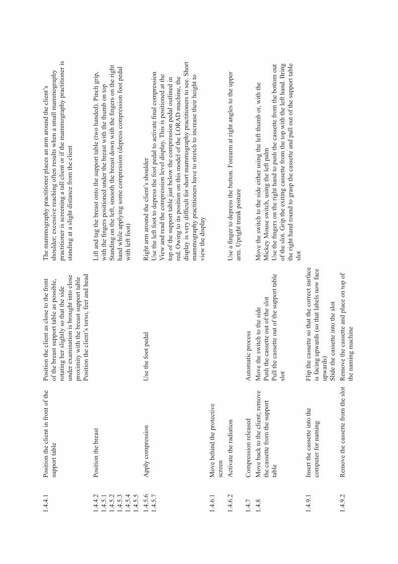

TA
tas
k nu
mbe
rT
ask
elem
ent
Con
trol
/equ
ipm
ent
acti
onP
hysi
cal a
ctio
n
�.�
Cra
nioc
auda
l vie
w:
left
bre
ast
1.4.
1.1
inse
rt a
new
cas
sette
into
the
supp
ort t
able
Pick
up
the
new
cas
sette
. Flip
the
cass
ette
so
that
the
corr
ect s
urfa
ce is
fa
cing
upw
ards
(w
ith th
e la
bels
fac
ing
dow
nwar
ds)
mov
e th
e sw
itch
to th
e si
de, e
ither
usi
ng
righ
t thu
mb
or w
ith t
he p
alm
for
the
mic
key
mou
se s
witc
hSl
ide
the
cass
ette
into
the
slot
usi
ng th
e le
ft h
and
Twis
ting
of th
e w
rist
fro
m s
upin
e to
pro
neSl
ight
ben
ding
to v
isua
lly lo
cate
the
fron
t of
the
film
cas
sette
in th
e fil
m
supp
ort t
able
The
lock
ing
mec
hani
sm s
witc
h re
quir
es e
xces
sive
for
ce, w
hich
is a
pplie
d by
the
thum
b; th
is c
ause
s lo
cal i
mpi
ngem
ent o
n th
e th
umb
The
re is
hyp
erex
tens
ion
of th
e th
umb
whe
n pu
shin
g th
e fil
m c
asse
tte in
to
the
film
sup
port
tabl
e; th
is f
orce
is a
pplie
d by
the
thum
b w
hile
the
wri
st is
de
viat
ed
1.4.
2St
ick
the
appr
opri
ate
view
ing
num
bers
ont
o th
e su
ppor
t tab
le
1.4.
3.2
Adj
ust t
he h
eigh
t of
the
supp
ort
tabl
eU
se th
e fo
ot p
edal
or
switc
h on
the
mac
hine
Rig
ht f
oot.
Lef
t or
righ
t han
d
1.4.
4.1
Posi
tion
the
clie
ntPo
sitio
n th
e cl
ient
clo
se to
the
fron
t of
the
brea
st s
uppo
rt ta
ble,
rot
atin
g he
r sl
ight
ly
so th
at th
e si
de u
nder
exa
min
atio
n is
br
ough
t int
o cl
ose
prox
imity
with
the
brea
st s
uppo
rt ta
ble
Posi
tion
the
clie
nt’s
tors
o, f
eet a
nd h
ead
The
mam
mog
raph
y pr
actit
ione
r pl
aces
an
arm
aro
und
the
clie
nt’s
sh
ould
er; e
xces
sive
rea
chin
g of
ten
resu
lts w
hen
a sm
all m
amm
ogra
phy
prac
titio
ner
is s
cree
ning
a ta
ll cl
ient
or
if th
e m
amm
ogra
phy
prac
titio
ner
is
stan
ding
at a
slig
ht d
ista
nce
from
the
clie
nt
1.4.
4.2
1.4.
5.1
1.4.
5.2
1.4.
5.3
1.4.
5.4
1.4.
5.5
Posi
tion
the
brea
stL
ift a
nd tu
g th
e br
east
ont
o th
e su
ppor
t tab
le (
two
hand
ed).
Pin
ch g
rip,
w
ith th
e fin
gers
pos
ition
ed u
nder
bre
ast w
ith th
e th
umb
on to
pSt
andi
ng o
n th
e ri
ght,
smoo
th th
e br
east
dow
n w
ith th
e fin
gers
on
the
righ
t ha
nd w
hile
app
lyin
g so
me
com
pres
sion
(de
pres
s co
mpr
essi
on f
oot p
edal
w
ith th
e le
ft f
oot)
1.4.
5.6
1.4.
5.7
App
ly c
ompr
essi
onU
se th
e fo
ot p
edal
Lef
t arm
aro
und
the
clie
nt’s
sho
ulde
rU
se th
e ri
ght f
oot t
o de
pres
s th
e fo
ot p
edal
to a
ctiv
ate
final
com
pres
sion
Vie
w a
nd r
ead
the
com
pres
sion
leve
l dis
play
. Thi
s is
pos
ition
ed a
t the
to
p of
the
supp
ort t
able
just
bel
ow th
e co
mpr
essi
on p
edal
out
lined
in
red.
Ow
ing
to it
s po
sitio
n on
this
mod
el o
f th
e L
OR
AD
mac
hine
, the
di
spla
y is
ver
y di
fficu
lt fo
r sh
ort m
amm
ogra
phy
prac
titio
ners
to s
ee. S
hort
m
amm
ogra
phy
prac
titio
ners
hav
e to
str
etch
to in
crea
se th
eir
heig
ht to
vi
ew th
e di
spla
y
1.4.
6.1
mov
e be
hind
the
prot
ectiv
e sc
reen
1.4.
6.2
Act
ivat
e th
e ra
diat
ion
Use
a fi
nger
to d
epre
ss th
e bu
tton.
For
earm
at r
ight
ang
les
to th
e up
per
arm
. Upr
ight
trun
k po
stur
e
1.4.
8R
emov
e th
e ca
sset
te f
rom
the
supp
ort t
able
mov
e ba
ck to
the
clie
ntm
ove
the
switc
h to
the
side
Push
the
cass
ette
out
of
the
slot
Pull
the
cass
ette
out
of
the
supp
ort t
able
sl
ot
mov
e th
e sw
itch
to th
e si
de e
ither
usi
ng th
e th
umb
or, w
ith th
e m
icke
y m
ouse
sw
itch,
usi
ng th
e le
ft p
alm
Use
the
finge
rs o
n th
e ri
ght h
and
to p
ush
the
cass
ette
out
of
the
slot
. Gri
p th
e ex
iting
cas
sette
with
the
left
han
d. B
ring
the
righ
t han
d ro
und
to g
rasp
th
e ca
sset
te a
nd p
ull i
t out
of
the
supp
ort t
able
slo
t
1.4.
9.1
inse
rt th
e ca
sset
te in
to th
e na
min
g m
achi
neFl
ip th
e ca
sset
te s
o th
at th
e co
rrec
t sur
face
is
fac
ing
upw
ards
(so
that
the
labe
ls n
ow
face
upw
ards
)Sl
ide
the
cass
ette
into
the
slot
1.4.
9.2
Rem
ove
the
cass
ette
fro
m th
e na
min
g m
achi
ne a
nd s
tack
on
top
of th
e na
min
g m
achi
ne
Pull
the
cass
ette
out
of
the
slot
Stac
k on
the
mac
hine
with
the
labe
ls
faci
ng u
p
If th
e ce
ntre
has
onl
y on
e si
ze
of c
asse
tte (
the
smal
ler
size
),
RE
PEA
T f
or la
rger
bre
asts
(if
the
tota
l bre
ast i
s no
t cap
ture
d on
one
ca
sset
te)
Tab
le �
Con
tinue
d

TA
tas
k nu
mbe
rT
ask
elem
ent
Con
trol
/equ
ipm
ent
acti
onP
hysi
cal a
ctio
n
�.�
Cra
nioc
auda
l vie
w:
left
bre
ast
1.4.
1.1
inse
rt a
new
cas
sette
into
the
supp
ort t
able
Pick
up
the
new
cas
sette
. Flip
the
cass
ette
so
that
the
corr
ect s
urfa
ce is
fa
cing
upw
ards
(w
ith th
e la
bels
fac
ing
dow
nwar
ds)
mov
e th
e sw
itch
to th
e si
de, e
ither
usi
ng
righ
t thu
mb
or w
ith t
he p
alm
for
the
mic
key
mou
se s
witc
hSl
ide
the
cass
ette
into
the
slot
usi
ng th
e le
ft h
and
Twis
ting
of th
e w
rist
fro
m s
upin
e to
pro
neSl
ight
ben
ding
to v
isua
lly lo
cate
the
fron
t of
the
film
cas
sette
in th
e fil
m
supp
ort t
able
The
lock
ing
mec
hani
sm s
witc
h re
quir
es e
xces
sive
for
ce, w
hich
is a
pplie
d by
the
thum
b; th
is c
ause
s lo
cal i
mpi
ngem
ent o
n th
e th
umb
The
re is
hyp
erex
tens
ion
of th
e th
umb
whe
n pu
shin
g th
e fil
m c
asse
tte in
to
the
film
sup
port
tabl
e; th
is f
orce
is a
pplie
d by
the
thum
b w
hile
the
wri
st is
de
viat
ed
1.4.
2St
ick
the
appr
opri
ate
view
ing
num
bers
ont
o th
e su
ppor
t tab
le
1.4.
3.2
Adj
ust t
he h
eigh
t of
the
supp
ort
tabl
eU
se th
e fo
ot p
edal
or
switc
h on
the
mac
hine
Rig
ht f
oot.
Lef
t or
righ
t han
d
1.4.
4.1
Posi
tion
the
clie
ntPo
sitio
n th
e cl
ient
clo
se to
the
fron
t of
the
brea
st s
uppo
rt ta
ble,
rot
atin
g he
r sl
ight
ly
so th
at th
e si
de u
nder
exa
min
atio
n is
br
ough
t int
o cl
ose
prox
imity
with
the
brea
st s
uppo
rt ta
ble
Posi
tion
the
clie
nt’s
tors
o, f
eet a
nd h
ead
The
mam
mog
raph
y pr
actit
ione
r pl
aces
an
arm
aro
und
the
clie
nt’s
sh
ould
er; e
xces
sive
rea
chin
g of
ten
resu
lts w
hen
a sm
all m
amm
ogra
phy
prac
titio
ner
is s
cree
ning
a ta
ll cl
ient
or
if th
e m
amm
ogra
phy
prac
titio
ner
is
stan
ding
at a
slig
ht d
ista
nce
from
the
clie
nt
1.4.
4.2
1.4.
5.1
1.4.
5.2
1.4.
5.3
1.4.
5.4
1.4.
5.5
Posi
tion
the
brea
stL
ift a
nd tu
g th
e br
east
ont
o th
e su
ppor
t tab
le (
two
hand
ed).
Pin
ch g
rip,
w
ith th
e fin
gers
pos
ition
ed u
nder
bre
ast w
ith th
e th
umb
on to
pSt
andi
ng o
n th
e ri
ght,
smoo
th th
e br
east
dow
n w
ith th
e fin
gers
on
the
righ
t ha
nd w
hile
app
lyin
g so
me
com
pres
sion
(de
pres
s co
mpr
essi
on f
oot p
edal
w
ith th
e le
ft f
oot)
1.4.
5.6
1.4.
5.7
App
ly c
ompr
essi
onU
se th
e fo
ot p
edal
Lef
t arm
aro
und
the
clie
nt’s
sho
ulde
rU
se th
e ri
ght f
oot t
o de
pres
s th
e fo
ot p
edal
to a
ctiv
ate
final
com
pres
sion
Vie
w a
nd r
ead
the
com
pres
sion
leve
l dis
play
. Thi
s is
pos
ition
ed a
t the
to
p of
the
supp
ort t
able
just
bel
ow th
e co
mpr
essi
on p
edal
out
lined
in
red.
Ow
ing
to it
s po
sitio
n on
this
mod
el o
f th
e L
OR
AD
mac
hine
, the
di
spla
y is
ver
y di
fficu
lt fo
r sh
ort m
amm
ogra
phy
prac
titio
ners
to s
ee. S
hort
m
amm
ogra
phy
prac
titio
ners
hav
e to
str
etch
to in
crea
se th
eir
heig
ht to
vi
ew th
e di
spla
y
1.4.
6.1
mov
e be
hind
the
prot
ectiv
e sc
reen
1.4.
6.2
Act
ivat
e th
e ra
diat
ion
Use
a fi
nger
to d
epre
ss th
e bu
tton.
For
earm
at r
ight
ang
les
to th
e up
per
arm
. Upr
ight
trun
k po
stur
e
1.4.
8R
emov
e th
e ca
sset
te f
rom
the
supp
ort t
able
mov
e ba
ck to
the
clie
ntm
ove
the
switc
h to
the
side
Push
the
cass
ette
out
of
the
slot
Pull
the
cass
ette
out
of
the
supp
ort t
able
sl
ot
mov
e th
e sw
itch
to th
e si
de e
ither
usi
ng th
e th
umb
or, w
ith th
e m
icke
y m
ouse
sw
itch,
usi
ng th
e le
ft p
alm
Use
the
finge
rs o
n th
e ri
ght h
and
to p
ush
the
cass
ette
out
of
the
slot
. Gri
p th
e ex
iting
cas
sette
with
the
left
han
d. B
ring
the
righ
t han
d ro
und
to g
rasp
th
e ca
sset
te a
nd p
ull i
t out
of
the
supp
ort t
able
slo
t
1.4.
9.1
inse
rt th
e ca
sset
te in
to th
e na
min
g m
achi
neFl
ip th
e ca
sset
te s
o th
at th
e co
rrec
t sur
face
is
fac
ing
upw
ards
(so
that
the
labe
ls n
ow
face
upw
ards
)Sl
ide
the
cass
ette
into
the
slot
1.4.
9.2
Rem
ove
the
cass
ette
fro
m th
e na
min
g m
achi
ne a
nd s
tack
on
top
of th
e na
min
g m
achi
ne
Pull
the
cass
ette
out
of
the
slot
Stac
k on
the
mac
hine
with
the
labe
ls
faci
ng u
p
If th
e ce
ntre
has
onl
y on
e si
ze
of c
asse
tte (
the
smal
ler
size
),
RE
PEA
T f
or la
rger
bre
asts
(if
the
tota
l bre
ast i
s no
t cap
ture
d on
one
ca
sset
te)

TA
tas
k nu
mbe
rT
ask
elem
ent
Con
trol
/equ
ipm
ent
acti
onP
hysi
cal a
ctio
n
�.�
Med
iola
tera
l vie
w:
left
bre
ast
1.4.
1.1
inse
rt a
new
cas
sette
Pick
up
the
new
cas
sette
Flip
the
cass
ette
so
that
the
corr
ect
surf
ace
is f
acin
g up
war
ds (
labe
ls f
acin
g do
wnw
ards
)m
ove
the
switc
h to
the
side
eith
er u
sing
th
e ri
ght t
hum
b or
the
palm
for
the
mic
key
mou
se s
witc
hSl
ide
the
cass
ette
into
the
slot
usi
ng th
e le
ft h
and
Twis
ting
of th
e w
rist
fro
m s
upin
atio
n to
pro
natio
nFo
rces
app
lied
by th
e th
umb.
Som
e im
ping
emen
t on
the
thum
b
1.4.
2L
abel
the
supp
ort t
able
with
the
corr
ect v
iew
ing
angl
e la
bel
1.4.
3.1
Adj
ust t
he r
otat
ion
The
sw
itch
is lo
cate
d on
the
rear
of
the
mac
hine
arm
/hea
d or
at t
he to
p of
the
arm
/hea
d
Lef
t or
righ
t han
d
1.4.
3.2
Rea
djus
t the
hei
ght i
f re
quir
edSw
itch
on th
e m
achi
neL
eft o
r ri
ght h
and
1.4.
4.1
Posi
tion
the
clie
nt a
nd m
ove
her
arm
; ens
ure
her
stom
ach
and
othe
r br
east
are
not
pro
trud
ing
into
vie
w
Posi
tion
the
clie
nt’s
left
arm
to h
old
the
left
han
dle
on th
e m
achi
nem
amm
ogra
phy
prac
titio
ners
use
thei
r ar
ms
and
body
to tw
ist a
nd b
end
the
clie
nt to
lean
sid
eway
s ov
er to
the
left
to a
ssis
t in
posi
tioni
ng o
f th
e br
east
1.4.
4.2
1.4.
5.1
1.4.
5.2
1.4.
5.3
1.4.
5.4
1.4.
5.5
Posi
tion
the
brea
stL
ifts
and
cup
s th
e br
east
. if
the
clie
nt is
sm
all,
then
the
mam
mog
raph
y pr
actit
ione
r m
ay h
ave
to s
toop
to a
dequ
atel
y gr
asp
the
brea
stif
sta
ndin
g be
hind
the
clie
nt, t
he m
amm
ogra
phy
prac
titio
ner
may
not
be
able
to o
btai
n a
good
vie
w o
f th
e br
east
ove
r th
e cl
ient
’s s
houl
der
and
so
will
hav
e to
twis
t or
bend
acc
ordi
ngly
Whe
n th
e br
east
is c
uppe
d, th
e th
umb
is o
ften
hyp
erex
tend
ed a
nd th
e w
rist
is in
ext
rem
e ul
nar
devi
atio
n (i
f th
e pa
lm is
use
d)Po
sitio
ns th
e br
east
on
the
brea
st s
uppo
rt ta
ble
to e
nsur
e th
at th
e ni
pple
is
app
ropr
iate
ly p
ositi
oned
and
the
oute
r qu
adra
nt o
f th
e br
east
is b
roug
ht
into
con
tact
with
the
brea
st s
uppo
rt ta
ble.
Ens
ures
that
ther
e ar
e no
ar
tefa
cts
or s
kin
fold
sm
ay h
ave
to b
end
to o
bser
ve th
e br
east
, dep
endi
ng o
n th
e he
ight
of
both
th
e m
amm
ogra
phy
prac
titio
ner
and
the
clie
ntSt
retc
hing
of
the
arm
at t
he m
axim
um r
ange
of
mot
ion
acro
ss th
e br
east
su
ppor
t tab
le in
ord
er to
rea
ch th
e po
sitio
n of
the
brea
stB
oth
legs
ben
t and
pos
ition
ed a
part
to lo
wer
ove
rall
body
pos
ition
. Thi
s po
stur
e en
able
s th
e m
amm
ogra
phy
prac
titio
ner
to v
iew
the
brea
st, w
hich
ot
herw
ise
wou
ld b
e ob
scur
ed b
y th
e he
ad o
f th
e m
achi
neT
he n
eck
is e
xten
ded
to v
iew
the
brea
st. B
oth
arm
s ar
e ou
tstr
etch
ed w
ith
the
uppe
r ar
m a
t 90
degr
ees
to th
e to
rso
One
han
d is
use
d to
lift
the
brea
stT
he r
ight
han
d th
umb
is f
ully
ext
ende
d an
d is
use
d to
sup
port
the
wei
ght
of b
reas
t and
to p
ush
the
brea
st u
p to
the
corr
ect p
ositi
on o
n th
e su
ppor
t ta
ble.
Use
of
the
thum
b al
low
s th
e fo
rear
m a
nd w
rist
to s
tay
in li
ne.
How
ever
, the
thum
b is
use
d in
a w
eak
posi
tion
(ful
ly e
xten
ded)
to ta
ke th
e fu
ll w
eigh
t of
the
brea
st. T
he u
se o
f th
e th
umb
in th
is p
ostu
re w
ith s
uch
a lo
ad p
lace
s th
e th
umb
and
wri
st a
t ris
k of
inju
ry, p
artic
ular
ly w
ith th
e ra
te
of r
epet
ition
and
dur
atio
n of
this
pos
ture
An
alte
rnat
ive
tech
niqu
e is
to u
se th
e fin
gers
to s
uppo
rt a
nd p
ush
the
brea
st in
to p
ositi
on. T
his
requ
ires
the
elbo
w to
be
held
out
war
ds to
rot
ate
the
fore
arm
so
that
the
palm
of
the
righ
t han
d is
abl
e to
pus
h up
aga
inst
th
e br
east
. Thi
s w
ill le
ad to
aw
kwar
d ro
tatio
n of
the
shou
lder
and
elb
ow
join
tsT
he o
ther
han
d is
use
d to
kee
p th
e sh
ould
er, s
tom
ach
and
othe
r br
east
fr
om p
rotr
udin
g in
to th
e fie
ld o
f vi
ew f
or im
agin
gSo
me
mam
mog
raph
y pr
actit
ione
rs a
re s
tart
ing
to c
ondu
ct th
is p
art o
f th
e ta
sk w
hile
sea
ted
Tab
le �
Con
tinue
d

TA
tas
k nu
mbe
rT
ask
elem
ent
Con
trol
/equ
ipm
ent
acti
onP
hysi
cal a
ctio
n
�.�
Med
iola
tera
l vie
w:
left
bre
ast
1.4.
1.1
inse
rt a
new
cas
sette
Pick
up
the
new
cas
sette
Flip
the
cass
ette
so
that
the
corr
ect
surf
ace
is f
acin
g up
war
ds (
labe
ls f
acin
g do
wnw
ards
)m
ove
the
switc
h to
the
side
eith
er u
sing
th
e ri
ght t
hum
b or
the
palm
for
the
mic
key
mou
se s
witc
hSl
ide
the
cass
ette
into
the
slot
usi
ng th
e le
ft h
and
Twis
ting
of th
e w
rist
fro
m s
upin
atio
n to
pro
natio
nFo
rces
app
lied
by th
e th
umb.
Som
e im
ping
emen
t on
the
thum
b
1.4.
2L
abel
the
supp
ort t
able
with
the
corr
ect v
iew
ing
angl
e la
bel
1.4.
3.1
Adj
ust t
he r
otat
ion
The
sw
itch
is lo
cate
d on
the
rear
of
the
mac
hine
arm
/hea
d or
at t
he to
p of
the
arm
/hea
d
Lef
t or
righ
t han
d
1.4.
3.2
Rea
djus
t the
hei
ght i
f re
quir
edSw
itch
on th
e m
achi
neL
eft o
r ri
ght h
and
1.4.
4.1
Posi
tion
the
clie
nt a
nd m
ove
her
arm
; ens
ure
her
stom
ach
and
othe
r br
east
are
not
pro
trud
ing
into
vie
w
Posi
tion
the
clie
nt’s
left
arm
to h
old
the
left
han
dle
on th
e m
achi
nem
amm
ogra
phy
prac
titio
ners
use
thei
r ar
ms
and
body
to tw
ist a
nd b
end
the
clie
nt to
lean
sid
eway
s ov
er to
the
left
to a
ssis
t in
posi
tioni
ng o
f th
e br
east
1.4.
4.2
1.4.
5.1
1.4.
5.2
1.4.
5.3
1.4.
5.4
1.4.
5.5
Posi
tion
the
brea
stL
ifts
and
cup
s th
e br
east
. if
the
clie
nt is
sm
all,
then
the
mam
mog
raph
y pr
actit
ione
r m
ay h
ave
to s
toop
to a
dequ
atel
y gr
asp
the
brea
stif
sta
ndin
g be
hind
the
clie
nt, t
he m
amm
ogra
phy
prac
titio
ner
may
not
be
able
to o
btai
n a
good
vie
w o
f th
e br
east
ove
r th
e cl
ient
’s s
houl
der
and
so
will
hav
e to
twis
t or
bend
acc
ordi
ngly
Whe
n th
e br
east
is c
uppe
d, th
e th
umb
is o
ften
hyp
erex
tend
ed a
nd th
e w
rist
is in
ext
rem
e ul
nar
devi
atio
n (i
f th
e pa
lm is
use
d)Po
sitio
ns th
e br
east
on
the
brea
st s
uppo
rt ta
ble
to e
nsur
e th
at th
e ni
pple
is
app
ropr
iate
ly p
ositi
oned
and
the
oute
r qu
adra
nt o
f th
e br
east
is b
roug
ht
into
con
tact
with
the
brea
st s
uppo
rt ta
ble.
Ens
ures
that
ther
e ar
e no
ar
tefa
cts
or s
kin
fold
sm
ay h
ave
to b
end
to o
bser
ve th
e br
east
, dep
endi
ng o
n th
e he
ight
of
both
th
e m
amm
ogra
phy
prac
titio
ner
and
the
clie
ntSt
retc
hing
of
the
arm
at t
he m
axim
um r
ange
of
mot
ion
acro
ss th
e br
east
su
ppor
t tab
le in
ord
er to
rea
ch th
e po
sitio
n of
the
brea
stB
oth
legs
ben
t and
pos
ition
ed a
part
to lo
wer
ove
rall
body
pos
ition
. Thi
s po
stur
e en
able
s th
e m
amm
ogra
phy
prac
titio
ner
to v
iew
the
brea
st, w
hich
ot
herw
ise
wou
ld b
e ob
scur
ed b
y th
e he
ad o
f th
e m
achi
neT
he n
eck
is e
xten
ded
to v
iew
the
brea
st. B
oth
arm
s ar
e ou
tstr
etch
ed w
ith
the
uppe
r ar
m a
t 90
degr
ees
to th
e to
rso
One
han
d is
use
d to
lift
the
brea
stT
he r
ight
han
d th
umb
is f
ully
ext
ende
d an
d is
use
d to
sup
port
the
wei
ght
of b
reas
t and
to p
ush
the
brea
st u
p to
the
corr
ect p
ositi
on o
n th
e su
ppor
t ta
ble.
Use
of
the
thum
b al
low
s th
e fo
rear
m a
nd w
rist
to s
tay
in li
ne.
How
ever
, the
thum
b is
use
d in
a w
eak
posi
tion
(ful
ly e
xten
ded)
to ta
ke th
e fu
ll w
eigh
t of
the
brea
st. T
he u
se o
f th
e th
umb
in th
is p
ostu
re w
ith s
uch
a lo
ad p
lace
s th
e th
umb
and
wri
st a
t ris
k of
inju
ry, p
artic
ular
ly w
ith th
e ra
te
of r
epet
ition
and
dur
atio
n of
this
pos
ture
An
alte
rnat
ive
tech
niqu
e is
to u
se th
e fin
gers
to s
uppo
rt a
nd p
ush
the
brea
st in
to p
ositi
on. T
his
requ
ires
the
elbo
w to
be
held
out
war
ds to
rot
ate
the
fore
arm
so
that
the
palm
of
the
righ
t han
d is
abl
e to
pus
h up
aga
inst
th
e br
east
. Thi
s w
ill le
ad to
aw
kwar
d ro
tatio
n of
the
shou
lder
and
elb
ow
join
tsT
he o
ther
han
d is
use
d to
kee
p th
e sh
ould
er, s
tom
ach
and
othe
r br
east
fr
om p
rotr
udin
g in
to th
e fie
ld o
f vi
ew f
or im
agin
gSo
me
mam
mog
raph
y pr
actit
ione
rs a
re s
tart
ing
to c
ondu
ct th
is p
art o
f th
e ta
sk w
hile
sea
ted

TA
tas
k nu
mbe
rT
ask
elem
ent
Con
trol
/equ
ipm
ent
acti
onP
hysi
cal a
ctio
n
1.4.
5.6
1.4.
5.7
App
ly c
ompr
essi
onV
isua
lly lo
cate
the
peda
l; m
ay n
eed
to tw
ist t
o ob
serv
e th
e pe
dal
Use
the
righ
t foo
t to
depr
ess
the
foot
ped
al to
act
ivat
e co
mpr
essi
on. T
his
is c
ondu
cted
whi
le s
uppo
rtin
g an
d sm
ooth
ing
the
left
bre
ast t
o m
aint
ain
its c
orre
ct p
ositi
on o
n th
e su
ppor
t tab
le. O
nce
som
e co
mpr
essi
on h
as
been
app
lied
(suf
ficie
nt to
hol
d th
e br
east
in p
lace
), th
e m
amm
ogra
phy
prac
titio
ner
rem
oves
her
han
d an
d ap
plie
s fu
ll co
mpr
essi
onV
iew
and
rea
d th
e co
mpr
essi
on le
vel d
ispl
ay. T
his
is m
ade
slig
htly
eas
ier
than
in th
e ca
udal
vie
w a
s th
e di
spla
y is
rot
ated
; the
refo
re th
e an
gles
use
d pr
ovid
e a
bette
r vi
ew o
f th
e di
spla
y fo
r al
l sta
ture
s of
mam
mog
raph
y pr
actit
ione
rC
ombi
ned
use
of th
e fo
ot p
edal
and
the
hand
to m
aint
ain
the
posi
tion
of th
e br
east
oft
en r
esul
ts in
asy
mm
etri
cal p
ostu
re a
s th
e bo
dy w
eigh
t is
carr
ied
by th
e ot
her
foot
(no
n-op
erat
ing
foot
). i
n ad
ditio
n, th
is le
g re
mai
ns
bent
with
the
trun
k sl
ight
ly s
toop
ed a
nd th
e ne
ck is
kep
t ext
ende
d to
m
aint
ain
a vi
ew o
f th
e br
east
dur
ing
the
final
com
pres
sion
Act
ivat
ion
of th
e pe
dal p
lace
s un
equa
l dis
trib
utio
n of
the
wei
ght o
n on
e le
g, c
ausi
ng s
tatic
load
ing
of th
at le
g an
d an
uns
tabl
e sl
ight
ly
asym
met
rica
l pos
ture
1.4.
6.1
mov
e be
hind
the
prot
ectiv
e sc
reen
1.4.
6.2
Act
ivat
e th
e ra
diat
ion
Use
the
finge
r to
dep
ress
the
butto
n. F
orea
rm a
t rig
ht a
ngle
s to
the
uppe
r ar
m. U
prig
ht tr
unk
post
ure
1.4.
8R
emov
e th
e ca
sset
te f
rom
the
supp
ort t
able
mov
e th
e sw
itch
to th
e si
dePu
sh th
e ca
sset
te o
ut o
f th
e sl
otPu
ll th
e ca
sset
te o
ut o
f th
e su
ppor
t tab
le
slot
mov
e th
e sw
itch
to th
e si
de e
ither
usi
ng th
e th
umb
or, w
ith th
e m
icke
y m
ouse
sw
itch,
usi
ng th
e le
ft p
alm
Use
fing
ers
on th
e ri
ght h
and
to p
ush
the
cass
ette
out
of
the
slot
. Gri
p th
e ex
iting
cas
sette
with
the
left
han
d. B
ring
the
righ
t han
d ro
und
to g
rasp
the
cass
ette
and
pul
l it o
ut o
f th
e su
ppor
t tab
le s
lot
1.4.
9.1
inse
rt th
e ca
sset
te in
to th
e na
min
g m
achi
neFl
ip th
e ca
sset
te s
o th
at th
e co
rrec
t sur
face
is
fac
ing
upw
ards
(so
that
labe
ls n
ow f
ace
upw
ards
)Sl
ide
the
cass
ette
into
the
slot
1.4.
9.2
Rem
ove
the
cass
ette
fro
m th
e na
min
g m
achi
ne a
nd s
tack
on
top
of th
e na
min
g m
achi
ne
Pull
the
cass
ette
out
of
the
slot
Stac
k on
the
mac
hine
with
the
labe
ls
faci
ng u
p
If th
e ce
ntre
has
onl
y on
e si
ze
of c
asse
tte (
the
smal
ler
size
),
RE
PEA
T f
or la
rger
bre
asts
(if
to
tal b
reas
t is
not c
aptu
red
on o
ne
cass
ette
)
�.�
Med
iola
tera
l vie
w:
righ
t br
east
1.4.
1.1
inse
rt a
new
cas
sette
Pick
up
the
new
cas
sette
Flip
the
cass
ette
so
that
the
corr
ect
surf
ace
is f
acin
g up
war
ds (
labe
ls f
acin
g do
wnw
ards
)m
ove
the
switc
h to
the
side
eith
er u
sing
th
e ri
ght t
hum
b or
the
palm
for
the
mic
key
mou
se s
witc
hSl
ide
the
cass
ette
into
the
slot
usi
ng th
e le
ft h
and
Twis
ting
of th
e w
rist
fro
m s
upin
atio
n to
pro
natio
nFo
rces
app
lied
by th
e th
umb.
Som
e im
ping
emen
t on
the
thum
b
1.4.
2L
abel
the
supp
ort t
able
with
the
corr
ect v
iew
ing
angl
e la
bel
1.4.
3.1
Rot
ate
the
arm
The
sw
itch
is lo
cate
d on
the
rear
of
the
mac
hine
hea
d/ar
m o
r at
the
top
of h
ead/
arm
Lef
t or
righ
t han
d
1.4.
3.2
Adj
ust t
he h
eigh
tU
se th
e fo
ot p
edal
or
switc
h on
the
mac
hine
Lef
t foo
tL
eft o
r ri
ght h
and
1.4.
4.1
Posi
tion
the
clie
ntPo
sitio
n th
e cl
ient
’s r
ight
arm
to h
old
the
left
han
dle
on th
e m
achi
ne.
Usi
ng a
rms
and
body
, the
mam
mog
raph
y pr
actit
ione
r tw
ists
and
ben
ds
the
clie
nt to
lean
sid
eway
s ov
er to
the
righ
t to
assi
st in
pos
ition
ing
of th
e br
east
1.4.
3.1
Rea
djus
t the
hei
ght i
f re
quir
edU
se th
e fo
ot p
edal
or
switc
h on
the
mac
hine
Lef
t foo
tL
eft o
r ri
ght h
and
1.4.
3.2
Rea
djus
t the
rot
atio
n if
req
uire
dT
he s
witc
h is
loca
ted
on th
e re
ar o
f th
e m
achi
ne h
ead/
arm
or
at th
e to
p of
hea
d/ar
m
Lef
t or
righ
t han
d
1.4.
4.1
Posi
tion
the
clie
nt a
nd m
ove
her
arm
; ens
ure
her
stom
ach
and
othe
r br
east
are
not
pro
trud
ing
into
vie
w
Ask
the
clie
nt to
pla
ce h
er r
ight
han
d on
her
hea
d an
d th
en p
ositi
on th
e cl
ient
’s r
ight
arm
to h
old
the
hand
le o
n th
e m
achi
ne. m
amm
ogra
phy
prac
titio
ners
use
thei
r ar
ms
and
body
to tw
ist a
nd b
end
the
clie
nt o
ver
to
the
righ
t sid
e to
ass
ist i
n po
sitio
ning
of
the
brea
st
Tab
le �
Con
tinue
d

TA
tas
k nu
mbe
rT
ask
elem
ent
Con
trol
/equ
ipm
ent
acti
onP
hysi
cal a
ctio
n
1.4.
5.6
1.4.
5.7
App
ly c
ompr
essi
onV
isua
lly lo
cate
the
peda
l; m
ay n
eed
to tw
ist t
o ob
serv
e th
e pe
dal
Use
the
righ
t foo
t to
depr
ess
the
foot
ped
al to
act
ivat
e co
mpr
essi
on. T
his
is c
ondu
cted
whi
le s
uppo
rtin
g an
d sm
ooth
ing
the
left
bre
ast t
o m
aint
ain
its c
orre
ct p
ositi
on o
n th
e su
ppor
t tab
le. O
nce
som
e co
mpr
essi
on h
as
been
app
lied
(suf
ficie
nt to
hol
d th
e br
east
in p
lace
), th
e m
amm
ogra
phy
prac
titio
ner
rem
oves
her
han
d an
d ap
plie
s fu
ll co
mpr
essi
onV
iew
and
rea
d th
e co
mpr
essi
on le
vel d
ispl
ay. T
his
is m
ade
slig
htly
eas
ier
than
in th
e ca
udal
vie
w a
s th
e di
spla
y is
rot
ated
; the
refo
re th
e an
gles
use
d pr
ovid
e a
bette
r vi
ew o
f th
e di
spla
y fo
r al
l sta
ture
s of
mam
mog
raph
y pr
actit
ione
rC
ombi
ned
use
of th
e fo
ot p
edal
and
the
hand
to m
aint
ain
the
posi
tion
of th
e br
east
oft
en r
esul
ts in
asy
mm
etri
cal p
ostu
re a
s th
e bo
dy w
eigh
t is
carr
ied
by th
e ot
her
foot
(no
n-op
erat
ing
foot
). i
n ad
ditio
n, th
is le
g re
mai
ns
bent
with
the
trun
k sl
ight
ly s
toop
ed a
nd th
e ne
ck is
kep
t ext
ende
d to
m
aint
ain
a vi
ew o
f th
e br
east
dur
ing
the
final
com
pres
sion
Act
ivat
ion
of th
e pe
dal p
lace
s un
equa
l dis
trib
utio
n of
the
wei
ght o
n on
e le
g, c
ausi
ng s
tatic
load
ing
of th
at le
g an
d an
uns
tabl
e sl
ight
ly
asym
met
rica
l pos
ture
1.4.
6.1
mov
e be
hind
the
prot
ectiv
e sc
reen
1.4.
6.2
Act
ivat
e th
e ra
diat
ion
Use
the
finge
r to
dep
ress
the
butto
n. F
orea
rm a
t rig
ht a
ngle
s to
the
uppe
r ar
m. U
prig
ht tr
unk
post
ure
1.4.
8R
emov
e th
e ca
sset
te f
rom
the
supp
ort t
able
mov
e th
e sw
itch
to th
e si
dePu
sh th
e ca
sset
te o
ut o
f th
e sl
otPu
ll th
e ca
sset
te o
ut o
f th
e su
ppor
t tab
le
slot
mov
e th
e sw
itch
to th
e si
de e
ither
usi
ng th
e th
umb
or, w
ith th
e m
icke
y m
ouse
sw
itch,
usi
ng th
e le
ft p
alm
Use
fing
ers
on th
e ri
ght h
and
to p
ush
the
cass
ette
out
of
the
slot
. Gri
p th
e ex
iting
cas
sette
with
the
left
han
d. B
ring
the
righ
t han
d ro
und
to g
rasp
the
cass
ette
and
pul
l it o
ut o
f th
e su
ppor
t tab
le s
lot
1.4.
9.1
inse
rt th
e ca
sset
te in
to th
e na
min
g m
achi
neFl
ip th
e ca
sset
te s
o th
at th
e co
rrec
t sur
face
is
fac
ing
upw
ards
(so
that
labe
ls n
ow f
ace
upw
ards
)Sl
ide
the
cass
ette
into
the
slot
1.4.
9.2
Rem
ove
the
cass
ette
fro
m th
e na
min
g m
achi
ne a
nd s
tack
on
top
of th
e na
min
g m
achi
ne
Pull
the
cass
ette
out
of
the
slot
Stac
k on
the
mac
hine
with
the
labe
ls
faci
ng u
p
If th
e ce
ntre
has
onl
y on
e si
ze
of c
asse
tte (
the
smal
ler
size
),
RE
PEA
T f
or la
rger
bre
asts
(if
to
tal b
reas
t is
not c
aptu
red
on o
ne
cass
ette
)
�.�
Med
iola
tera
l vie
w:
righ
t br
east
1.4.
1.1
inse
rt a
new
cas
sette
Pick
up
the
new
cas
sette
Flip
the
cass
ette
so
that
the
corr
ect
surf
ace
is f
acin
g up
war
ds (
labe
ls f
acin
g do
wnw
ards
)m
ove
the
switc
h to
the
side
eith
er u
sing
th
e ri
ght t
hum
b or
the
palm
for
the
mic
key
mou
se s
witc
hSl
ide
the
cass
ette
into
the
slot
usi
ng th
e le
ft h
and
Twis
ting
of th
e w
rist
fro
m s
upin
atio
n to
pro
natio
nFo
rces
app
lied
by th
e th
umb.
Som
e im
ping
emen
t on
the
thum
b
1.4.
2L
abel
the
supp
ort t
able
with
the
corr
ect v
iew
ing
angl
e la
bel
1.4.
3.1
Rot
ate
the
arm
The
sw
itch
is lo
cate
d on
the
rear
of
the
mac
hine
hea
d/ar
m o
r at
the
top
of h
ead/
arm
Lef
t or
righ
t han
d
1.4.
3.2
Adj
ust t
he h
eigh
tU
se th
e fo
ot p
edal
or
switc
h on
the
mac
hine
Lef
t foo
tL
eft o
r ri
ght h
and
1.4.
4.1
Posi
tion
the
clie
ntPo
sitio
n th
e cl
ient
’s r
ight
arm
to h
old
the
left
han
dle
on th
e m
achi
ne.
Usi
ng a
rms
and
body
, the
mam
mog
raph
y pr
actit
ione
r tw
ists
and
ben
ds
the
clie
nt to
lean
sid
eway
s ov
er to
the
righ
t to
assi
st in
pos
ition
ing
of th
e br
east
1.4.
3.1
Rea
djus
t the
hei
ght i
f re
quir
edU
se th
e fo
ot p
edal
or
switc
h on
the
mac
hine
Lef
t foo
tL
eft o
r ri
ght h
and
1.4.
3.2
Rea
djus
t the
rot
atio
n if
req
uire
dT
he s
witc
h is
loca
ted
on th
e re
ar o
f th
e m
achi
ne h
ead/
arm
or
at th
e to
p of
hea
d/ar
m
Lef
t or
righ
t han
d
1.4.
4.1
Posi
tion
the
clie
nt a
nd m
ove
her
arm
; ens
ure
her
stom
ach
and
othe
r br
east
are
not
pro
trud
ing
into
vie
w
Ask
the
clie
nt to
pla
ce h
er r
ight
han
d on
her
hea
d an
d th
en p
ositi
on th
e cl
ient
’s r
ight
arm
to h
old
the
hand
le o
n th
e m
achi
ne. m
amm
ogra
phy
prac
titio
ners
use
thei
r ar
ms
and
body
to tw
ist a
nd b
end
the
clie
nt o
ver
to
the
righ
t sid
e to
ass
ist i
n po
sitio
ning
of
the
brea
st

TA
tas
k nu
mbe
rT
ask
elem
ent
Con
trol
/equ
ipm
ent
acti
onP
hysi
cal a
ctio
n
1.4.
5.1
1.4.
5.2
1.4.
5.3
1.4.
5.4
1.4.
5.5
Posi
tion
the
brea
stL
ifts
and
cup
s th
e br
east
. if
the
clie
nt is
sm
all,
the
mam
mog
raph
y pr
actit
ione
r m
ay h
ave
to s
toop
to a
dequ
atel
y gr
asp
the
brea
stif
sta
ndin
g be
hind
the
clie
nt, t
he m
amm
ogra
phy
prac
titio
ner
may
not
be
able
to o
btai
n a
good
vie
w o
f th
e br
east
ove
r th
e cl
ient
’s s
houl
der
and
so
will
hav
e to
twis
t or
bend
acc
ordi
ngly
Whe
n th
e br
east
is c
uppe
d, th
e th
umb
is o
ften
hyp
erex
tend
ed a
nd th
e w
rist
is in
ext
rem
e ul
nar
devi
atio
n (i
f th
e pa
lm is
use
d)Po
sitio
ns th
e br
east
on
the
brea
st s
uppo
rt ta
ble
to e
nsur
e th
at th
e ni
pple
is
app
ropr
iate
ly p
ositi
oned
and
the
oute
r qu
adra
nt o
f th
e br
east
is b
roug
ht
into
con
tact
with
the
brea
st s
uppo
rt ta
ble.
Ens
ures
that
ther
e ar
e no
ar
tefa
cts
or s
kin
fold
sm
ay h
ave
to b
end
to o
bser
ve th
e br
east
, dep
endi
ng o
n th
e he
ight
of
both
th
e m
amm
ogra
phy
prac
titio
ner
and
the
clie
ntSt
retc
hing
of
the
arm
at t
he m
axim
um r
ange
of
mot
ion
acro
ss th
e br
east
su
ppor
t tab
le in
ord
er to
rea
ch th
e po
sitio
n of
the
brea
stB
oth
legs
ben
t and
pos
ition
ed a
part
to lo
wer
ove
rall
body
pos
ition
. Thi
s po
stur
e en
able
s th
e m
amm
ogra
phy
prac
titio
ner
to v
iew
the
brea
st, w
hich
ot
herw
ise
wou
ld b
e ob
scur
ed b
y th
e he
ad o
f th
e m
achi
neT
he n
eck
is e
xten
ded
to v
iew
the
brea
st. B
oth
arm
s ar
e ou
tstr
etch
ed w
ith
the
uppe
r ar
m a
t 90
degr
ees
to th
e to
rso
One
han
d is
use
d to
lift
the
brea
stT
he le
ft h
and
thum
b is
ful
ly e
xten
ded
and
is u
sed
to s
uppo
rt th
e w
eigh
t of
bre
ast a
nd to
pus
h th
e br
east
up
to th
e co
rrec
t pos
ition
on
the
supp
ort
tabl
e. U
se o
f th
e th
umb
allo
ws
the
fore
arm
and
wri
st to
sta
y in
line
. H
owev
er, t
he th
umb
is u
sed
in a
wea
k po
sitio
n (f
ully
ext
ende
d) to
take
the
full
wei
ght o
f th
e br
east
. The
use
of
the
thum
b in
this
pos
ture
with
suc
h a
load
pla
ces
the
thum
b an
d w
rist
at r
isk
of in
jury
, par
ticul
arly
with
the
rate
of
rep
etiti
on a
nd d
urat
ion
of th
is p
ostu
reA
n al
tern
ativ
e te
chni
que
is to
use
the
finge
rs to
sup
port
and
pus
h th
e br
east
into
pos
ition
. Thi
s re
quir
es th
e el
bow
to b
e he
ld o
utw
ards
to r
otat
e th
e fo
rear
m s
o th
at th
e pa
lm o
f th
e ri
ght h
and
is a
ble
to p
ush
up a
gain
st
the
brea
st. T
his
will
lead
to a
wkw
ard
rota
tion
of th
e sh
ould
er a
nd e
lbow
jo
ints
The
oth
er h
and
is u
sed
to k
eep
the
shou
lder
, sto
mac
h an
d ot
her
brea
st
from
pro
trud
ing
into
the
field
of
view
for
imag
ing
1.4.
5.6
1.4.
5.7
App
ly c
ompr
essi
onU
se th
e le
ft f
oot t
o de
pres
s th
e fo
ot p
edal
to a
ctiv
ate
com
pres
sion
. Thi
s is
con
duct
ed w
hile
sup
port
ing
and
smoo
thin
g th
e ri
ght b
reas
t to
mai
ntai
n its
cor
rect
pos
ition
on
the
supp
ort t
able
. Onc
e so
me
com
pres
sion
has
be
en a
pplie
d (s
uffic
ient
to h
old
the
brea
st in
pla
ce),
the
mam
mog
raph
y pr
actit
ione
r re
mov
es h
er h
and
and
appl
ies
full
com
pres
sion
usi
ng th
e fo
ot
peda
lV
iew
and
rea
d th
e co
mpr
essi
on le
vel d
ispl
ay. T
his
is m
ade
slig
htly
eas
ier
than
in th
e ca
udal
vie
w a
s th
e di
spla
y is
rot
ated
; the
refo
re th
e an
gles
use
d pr
ovid
e a
bette
r vi
ew o
f th
e di
spla
y fo
r al
l sta
ture
s of
mam
mog
raph
y pr
actit
ione
rC
ombi
ned
use
of th
e fo
ot p
edal
and
the
hand
s to
mai
ntai
n th
e po
sitio
n of
the
brea
st o
ften
res
ults
in a
sym
met
rica
l pos
ture
as
the
mam
mog
raph
y pr
actit
ione
r’s
wei
ght i
s ca
rrie
d by
the
othe
r fo
ot (
non-
oper
atin
g fo
ot);
this
is
nea
rly
a on
e fo
oted
sta
nce
as th
e ot
her
foot
is u
sed
to d
elic
atel
y ac
tivat
e an
d co
ntro
l the
com
pres
sion
ped
al. i
n ad
ditio
n, th
is le
g re
mai
ns b
ent w
ith
the
trun
k sl
ight
ly s
toop
ed a
nd th
e ne
ck is
kep
t ext
ende
d to
mai
ntai
n a
view
of
the
brea
st d
urin
g th
e fin
al c
ompr
essi
onA
ctiv
atio
n of
the
peda
l pla
ces
an u
nequ
al d
istr
ibut
ion
of w
eigh
t on
one
leg,
cau
sing
sta
tic lo
adin
g of
that
leg
and
an u
nsta
ble
slig
htly
as
ymm
etri
cal p
ostu
re
1.4.
6.1
mov
e be
hind
the
prot
ectiv
e sc
reen
1.4.
6.2
Act
ivat
e th
e ra
diat
ion
Use
a fi
nger
to d
epre
ss th
e bu
tton.
For
earm
at r
ight
ang
les
to th
e up
per
arm
. Upr
ight
trun
k po
stur
e
1.4.
8R
emov
e th
e ca
sset
te f
rom
the
supp
ort t
able
mov
e th
e sw
itch
to th
e si
dePu
sh th
e ca
sset
te o
ut o
f th
e sl
otPu
ll th
e ca
sset
te o
ut o
f th
e su
ppor
t tab
le
slot
mov
e th
e sw
itch
to s
ide
eith
er u
sing
one
thum
b or
, with
the
mic
key
mou
se s
witc
h, u
sing
the
left
pal
mU
se th
e fin
gers
on
the
righ
t han
d to
pus
h th
e ca
sset
te o
ut o
f th
e sl
ot. G
rip
the
exiti
ng c
asse
tte w
ith th
e le
ft h
and.
Bri
ng th
e ri
ght h
and
roun
d to
gra
sp
the
cass
ette
and
pul
l out
of
the
supp
ort t
able
slo
tPr
essu
re a
pplie
d to
rel
ease
the
cass
ette
, oft
en w
ith th
e fin
ger
or th
umb
exte
nded
1.4.
9.1
inse
rt th
e ca
sset
te in
to th
e na
min
g m
achi
neFl
ip th
e ca
sset
te s
o th
at th
e co
rrec
t sur
face
is
fac
ing
upw
ards
(so
that
the
labe
ls n
ow
face
upw
ards
)Sl
ide
the
cass
ette
into
the
slot
1.4.
9.2
Rem
ove
the
cass
ette
fro
m th
e na
min
g m
achi
ne a
nd s
tack
on
top
of th
e na
min
g m
achi
ne
Pull
out o
f th
e sl
otSt
ack
on th
e m
achi
ne w
ith la
bels
fac
ing
up
Tab
le �
Con
tinue
d

TA
tas
k nu
mbe
rT
ask
elem
ent
Con
trol
/equ
ipm
ent
acti
onP
hysi
cal a
ctio
n
1.4.
5.1
1.4.
5.2
1.4.
5.3
1.4.
5.4
1.4.
5.5
Posi
tion
the
brea
stL
ifts
and
cup
s th
e br
east
. if
the
clie
nt is
sm
all,
the
mam
mog
raph
y pr
actit
ione
r m
ay h
ave
to s
toop
to a
dequ
atel
y gr
asp
the
brea
stif
sta
ndin
g be
hind
the
clie
nt, t
he m
amm
ogra
phy
prac
titio
ner
may
not
be
able
to o
btai
n a
good
vie
w o
f th
e br
east
ove
r th
e cl
ient
’s s
houl
der
and
so
will
hav
e to
twis
t or
bend
acc
ordi
ngly
Whe
n th
e br
east
is c
uppe
d, th
e th
umb
is o
ften
hyp
erex
tend
ed a
nd th
e w
rist
is in
ext
rem
e ul
nar
devi
atio
n (i
f th
e pa
lm is
use
d)Po
sitio
ns th
e br
east
on
the
brea
st s
uppo
rt ta
ble
to e
nsur
e th
at th
e ni
pple
is
app
ropr
iate
ly p
ositi
oned
and
the
oute
r qu
adra
nt o
f th
e br
east
is b
roug
ht
into
con
tact
with
the
brea
st s
uppo
rt ta
ble.
Ens
ures
that
ther
e ar
e no
ar
tefa
cts
or s
kin
fold
sm
ay h
ave
to b
end
to o
bser
ve th
e br
east
, dep
endi
ng o
n th
e he
ight
of
both
th
e m
amm
ogra
phy
prac
titio
ner
and
the
clie
ntSt
retc
hing
of
the
arm
at t
he m
axim
um r
ange
of
mot
ion
acro
ss th
e br
east
su
ppor
t tab
le in
ord
er to
rea
ch th
e po
sitio
n of
the
brea
stB
oth
legs
ben
t and
pos
ition
ed a
part
to lo
wer
ove
rall
body
pos
ition
. Thi
s po
stur
e en
able
s th
e m
amm
ogra
phy
prac
titio
ner
to v
iew
the
brea
st, w
hich
ot
herw
ise
wou
ld b
e ob
scur
ed b
y th
e he
ad o
f th
e m
achi
neT
he n
eck
is e
xten
ded
to v
iew
the
brea
st. B
oth
arm
s ar
e ou
tstr
etch
ed w
ith
the
uppe
r ar
m a
t 90
degr
ees
to th
e to
rso
One
han
d is
use
d to
lift
the
brea
stT
he le
ft h
and
thum
b is
ful
ly e
xten
ded
and
is u
sed
to s
uppo
rt th
e w
eigh
t of
bre
ast a
nd to
pus
h th
e br
east
up
to th
e co
rrec
t pos
ition
on
the
supp
ort
tabl
e. U
se o
f th
e th
umb
allo
ws
the
fore
arm
and
wri
st to
sta
y in
line
. H
owev
er, t
he th
umb
is u
sed
in a
wea
k po
sitio
n (f
ully
ext
ende
d) to
take
the
full
wei
ght o
f th
e br
east
. The
use
of
the
thum
b in
this
pos
ture
with
suc
h a
load
pla
ces
the
thum
b an
d w
rist
at r
isk
of in
jury
, par
ticul
arly
with
the
rate
of
rep
etiti
on a
nd d
urat
ion
of th
is p
ostu
reA
n al
tern
ativ
e te
chni
que
is to
use
the
finge
rs to
sup
port
and
pus
h th
e br
east
into
pos
ition
. Thi
s re
quir
es th
e el
bow
to b
e he
ld o
utw
ards
to r
otat
e th
e fo
rear
m s
o th
at th
e pa
lm o
f th
e ri
ght h
and
is a
ble
to p
ush
up a
gain
st
the
brea
st. T
his
will
lead
to a
wkw
ard
rota
tion
of th
e sh
ould
er a
nd e
lbow
jo
ints
The
oth
er h
and
is u
sed
to k
eep
the
shou
lder
, sto
mac
h an
d ot
her
brea
st
from
pro
trud
ing
into
the
field
of
view
for
imag
ing
1.4.
5.6
1.4.
5.7
App
ly c
ompr
essi
onU
se th
e le
ft f
oot t
o de
pres
s th
e fo
ot p
edal
to a
ctiv
ate
com
pres
sion
. Thi
s is
con
duct
ed w
hile
sup
port
ing
and
smoo
thin
g th
e ri
ght b
reas
t to
mai
ntai
n its
cor
rect
pos
ition
on
the
supp
ort t
able
. Onc
e so
me
com
pres
sion
has
be
en a
pplie
d (s
uffic
ient
to h
old
the
brea
st in
pla
ce),
the
mam
mog
raph
y pr
actit
ione
r re
mov
es h
er h
and
and
appl
ies
full
com
pres
sion
usi
ng th
e fo
ot
peda
lV
iew
and
rea
d th
e co
mpr
essi
on le
vel d
ispl
ay. T
his
is m
ade
slig
htly
eas
ier
than
in th
e ca
udal
vie
w a
s th
e di
spla
y is
rot
ated
; the
refo
re th
e an
gles
use
d pr
ovid
e a
bette
r vi
ew o
f th
e di
spla
y fo
r al
l sta
ture
s of
mam
mog
raph
y pr
actit
ione
rC
ombi
ned
use
of th
e fo
ot p
edal
and
the
hand
s to
mai
ntai
n th
e po
sitio
n of
the
brea
st o
ften
res
ults
in a
sym
met
rica
l pos
ture
as
the
mam
mog
raph
y pr
actit
ione
r’s
wei
ght i
s ca
rrie
d by
the
othe
r fo
ot (
non-
oper
atin
g fo
ot);
this
is
nea
rly
a on
e fo
oted
sta
nce
as th
e ot
her
foot
is u
sed
to d
elic
atel
y ac
tivat
e an
d co
ntro
l the
com
pres
sion
ped
al. i
n ad
ditio
n, th
is le
g re
mai
ns b
ent w
ith
the
trun
k sl
ight
ly s
toop
ed a
nd th
e ne
ck is
kep
t ext
ende
d to
mai
ntai
n a
view
of
the
brea
st d
urin
g th
e fin
al c
ompr
essi
onA
ctiv
atio
n of
the
peda
l pla
ces
an u
nequ
al d
istr
ibut
ion
of w
eigh
t on
one
leg,
cau
sing
sta
tic lo
adin
g of
that
leg
and
an u
nsta
ble
slig
htly
as
ymm
etri
cal p
ostu
re
1.4.
6.1
mov
e be
hind
the
prot
ectiv
e sc
reen
1.4.
6.2
Act
ivat
e th
e ra
diat
ion
Use
a fi
nger
to d
epre
ss th
e bu
tton.
For
earm
at r
ight
ang
les
to th
e up
per
arm
. Upr
ight
trun
k po
stur
e
1.4.
8R
emov
e th
e ca
sset
te f
rom
the
supp
ort t
able
mov
e th
e sw
itch
to th
e si
dePu
sh th
e ca
sset
te o
ut o
f th
e sl
otPu
ll th
e ca
sset
te o
ut o
f th
e su
ppor
t tab
le
slot
mov
e th
e sw
itch
to s
ide
eith
er u
sing
one
thum
b or
, with
the
mic
key
mou
se s
witc
h, u
sing
the
left
pal
mU
se th
e fin
gers
on
the
righ
t han
d to
pus
h th
e ca
sset
te o
ut o
f th
e sl
ot. G
rip
the
exiti
ng c
asse
tte w
ith th
e le
ft h
and.
Bri
ng th
e ri
ght h
and
roun
d to
gra
sp
the
cass
ette
and
pul
l out
of
the
supp
ort t
able
slo
tPr
essu
re a
pplie
d to
rel
ease
the
cass
ette
, oft
en w
ith th
e fin
ger
or th
umb
exte
nded
1.4.
9.1
inse
rt th
e ca
sset
te in
to th
e na
min
g m
achi
neFl
ip th
e ca
sset
te s
o th
at th
e co
rrec
t sur
face
is
fac
ing
upw
ards
(so
that
the
labe
ls n
ow
face
upw
ards
)Sl
ide
the
cass
ette
into
the
slot
1.4.
9.2
Rem
ove
the
cass
ette
fro
m th
e na
min
g m
achi
ne a
nd s
tack
on
top
of th
e na
min
g m
achi
ne
Pull
out o
f th
e sl
otSt
ack
on th
e m
achi
ne w
ith la
bels
fac
ing
up

TA
tas
k nu
mbe
rT
ask
elem
ent
Con
trol
/equ
ipm
ent
acti
onP
hysi
cal a
ctio
n
If th
e ce
ntre
has
onl
y on
e si
ze
of c
asse
tte (
the
smal
ler
cass
ette
si
ze),
RE
PEA
T f
or la
rger
bre
asts
(i
f th
e to
tal b
reas
t can
not b
e ca
ptur
ed o
n on
e ca
sset
te)
1.6.
1E
nsur
e th
e pa
tient
ret
urns
to th
e ch
angi
ng r
oom
1.6.
2L
ock
the
door
1.7
Cle
an th
e m
achi
neR
etur
n to
the
mac
hine
1.8
Car
ry c
ompl
eted
cas
sette
s ou
t for
pr
oces
sing
Tab
le �
Tas
k el
emen
ts a
nd a
ctio
ns in
volv
ed in
film
pro
cess
ing
TA
tas
k nu
mbe
rT
ask
elem
ent
Con
trol
/equ
ipm
ent
acti
onP
hysi
cal a
ctio
n
Loa
d co
mpl
eted
cas
sette
s in
to
the
proc
esso
rR
otat
e th
e ca
sset
te s
o th
at la
bels
are
fac
ing
dow
nwar
dsin
sert
into
the
proc
esso
rW
hen
it be
eps,
rem
ove
the
empt
y ca
sset
te a
nd a
dd to
the
stac
k of
em
pty
cass
ette
sR
epea
t for
all
com
plet
ed c
asse
ttes
Ret
riev
e th
e de
velo
ped
film
s fr
om th
e ot
her
end
of th
e pr
oces
sor
Mou
nt th
e fil
ms
for
chec
king
if th
e im
ages
are
poo
r, re
take
x-
ray
film
sR
epea
t all
Stic
k on
bar
code
labe
ls
Plac
e in
to th
e fil
e fo
r m
ount
ing
Tab
le �
Con
tinue
d

NHSBSP October 2007 7�
Ergonomic Assessment of Mammography Units
APPENdIx 2: TASK ANALYSIS CHARTS
Chart 1 Analogue breast screening system (1) 74
Chart 2 Analogue breast screening system (2) 76
Chart 3 Digital breast screening system (1) 78
Chart 4 Digital breast screening system (2) 80
Chart 5 Digital breast screening (when all previous images are digital) 82

1x-ray
2Process film
3Mount x-rays
4Read x-ray
0.Breast screening mammography
1.1CollectnotesObtain new film cassettes
1Pick up four cassettes
2Carry cassettes into x-ray room, place on side
3Fill in client details form
1.2Invite client in
1Unlock door
2Ask client in and confirm date of birth and previous visits
4Brief client on procedure
1Assess if BST and cassettes appropriate size
1Load film cassette(ensure cassettelabel facing downwards)
Plan 1.4.1If yes DO 1 then EXITIf no DO 2 to 4 then 1 then EXIT
2Change BST
3Change compression paddle
4Get new larger cassettes
2Label BST with correct view
3Adjust BST position
4Placebreast on BST
5Position breast and apply compression
6Take mammogram
7Releasecompression
8Remove cassette
9Namecassette
1.6Return client to waitingroom
1.7Clean unit
3Lock door
1.8Carry four completed cassettes out for processing
2Adjust C-arm height
1Adjust C-arm rotation
Plan 1.4.3
If craniocaudal viewDO 2 REPEATuntil correct position then EXIT
If medio-lateral viewDO 1 to 2 repeat until position correct then EXIT
2Lift breast onto BST
1Position client arms and torso into correct position relative to the BST
1Holdbreast in position
2Apply slight compression
3Observe breast position. Release compression and reposition if required.
5When enough compression to hold breast in position remove hand hold on breast
6View compression level display
7Apply required full compression level
4If required reposition exposure chamber
Automatic machine action
1Mammo-graphermove to position behind screen
2Mammo-grapheractivateradiation
1Insert cassette into naming machine(ensure cassettelabel facing upwards)
2Remove cassettefrom naming machine and stack
1.5Client gets dressed
1.3Clientundresses
2Unlock door and show client out
1Inform client to return and wait in waitingroom
Plan 1.0
DO 1 to 11
Then EXIT
Plan 1.1
DO 1 to 3
Then EXIT
Plan 1.2
DO 1 to 4
Then EXIT
Plan 1.6
DO 1 to 2
Then EXIT
Plan 1.4.4
DO 1 to 2
IF BST not at correct height and rotation then REPEAT 1.4.3
IF BST correct height and rotation then EXIT
Plan 1.4.5
DO 1 to 3 repeated as necessary.
DO 4 to 7
Then EXIT
Plan 1.4.6
DO 1 to 2
Then EXIT
Plan 1.4.9
DO 1 to 2
Then EXIT
Chart 2 Chart 2
IF poor image REPEATappropriate image (1.4,.1.5,1.6,or 1.7)
1.4Take x-rays
Chart 1 Analogue breast screening system (1)
Plan 1. 4
DO 1 to 9 for cranio-caudal view of right breast
REPEAT for cranio-caudal view of left breast
REPEAT for medio-lateral view of left breast
REPEAT for medio-lateral view of right breast
Then EXIT
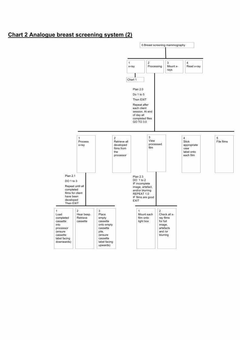
1x-ray
2Processing
3Mount x-rays
4Read x-ray
0.Breast screening mammography
Chart 1
1Process x-ray
2Retrieve all developed films from the processor
3Viewprocessed film
5File films
4Stickappropriateviewlabel onto each film
1Load completed cassette intoprocessor(ensure cassette label facing downwards)
2Hear beep.Retrievecassette
3Placeempty cassette onto empty cassette pile.(ensure cassette label facing upwards)
Plan 2.1
DO 1 to 3
Repeat until all completed films for client have been developed Then EXIT
1Mount each film onto light box
2Check all x-ray films for full image, artefacts and /or blurring
Plan 2.3DO 1 to 2IF incomplete image, artefact, and/or blurring REPEAT 1.0IF films are good EXIT
Plan 2.0
Do 1 to 5
Then EXIT
Repeat after each client session. At end of day all completed files GO TO 3.0
Chart 2 Analogue breast screening system (2)

1x-ray
2Processing
3Mount x-rays
4Read x-ray
0.Breast screening mammography
Chart 1
1Sort out files of a client
2Mount each x-ray film on viewing light box/screen
3Placeempty files inappropriate empty file box
1Retrievecurrent file of x-ray films
2Retrieveprevious file (3 year ago)
Plan 3.1
DO 1 to 3
Repeat until all completed films for client have been developed Then EXIT
1Pick out a x-ray film from file
2Scroll light box to gain a clear space for mounting
Plan 3.2DO 1 to 4Repeat for each film (typically 8 films per client) then EXIT
3Place film into correct position
4Insert x-ray film under wire of in appropriate slot
Plan 3.0
Do 1 to 3
Repeat for each client

1X-ray
2Process film
3Mount x-rays
4Read x-ray
0.Breast screening mammography
1.1CollectnotesObtain new film cassettes
1Pick up four cassettes
2Carry cassettes into x-ray room, place on side
3Fill in client details form
1.2Invite client in
1Unlock door
2Ask client in and confirm date of birth and previous visits
4Brief client on procedure
1Assess if BST and cassettes appropriate size
1Load film cassette(ensure cassettelabel facing downwards)
Plan 1.4.1.1, 1.4.2.1 1.4.3.1, 1.4.4.1
If yes DO 1 then EXIT
If no DO 2 to 4 then 1 then EXIT
2Change BST
3Change compression paddle
4Get new larger cassettes
2Label BST with correct view
3Adjust BST position
4Placebreast on BST
5Position breast and apply compression
6Take mammogram
7Releasecompression
8Remove cassette
9Checkdigitised image
1.6Return client to waitingroom
1.7Clean unit
3Lock door
1.8Carry four completed cassettes out for processing
2Adjust C-arm height
1Adjust C-arm rotation
Plan 1.4.3
If craniocaudal viewDO 2 REPEATuntil correct position then EXIT
If medio-lateral viewDO 1 to 2 repeat until position correct then EXIT
2Lift breast onto BST
1Position client arms and torso into correct position relative to the BST
1Holdbreast in position
2Apply slight compression
3Observe breast position. Release compression and reposition if required
5When enough compression to hold breast in position remove hand hold on breast
6View compression level display
7Apply required full compression level
4If required reposition exposure chamber
Automatic machine action
1Mammo-graphermove to position behind screen
2Mammo-grapheractivateradiation
1Check for full image, artefacts and /or blurring.ADUnumber between 800-1500
2Reset for next image
1.5Client gets dressed
1.3Clientundresses
2Unlock door and show client out
1Inform client when results will be posted through
Plan 1.0
DO 1 to 11
Then EXIT
Plan 1.1
DO 1 to 3
Then EXIT
Plan 1.2
DO 1 to 4
Then EXIT
Plan 1.6
DO 1 to 2
Then EXIT
Plan 1.4.4
DO 1 to 2
IF BST not at correct height and rotation then REPEAT 1.4.3
IF BST correct height and rotation then EXIT
Plan 1.4.5
DO 1 to 3 repeated as necessary
DO 4 to 7
Then EXIT
Plan 1.4.6
DO 1 to 2
Then EXIT
Plan 1.4.9
DO 1 to 2
Then EXIT
Chart 4 Chart 4
IF poor image REPEATappropriate image (1.4,.1.5,1.6,or 1.7)
Yellow indicates new or altered task
Grey indicates a task that no longer occurs
1. Input clientdetailsintocomputer
1.4Take x-rays
Chart 3 Digital breast screening system (1)
Plan 1. 4
DO 1 to 9 for cranio-caudal view of right breast
REPEAT for cranio-caudal view of left breast
REPEAT for medio-lateral view of left breast
REPEAT for medio-lateral view of right breast
Then EXIT
Check that there are four good images, press save and send

1x-ray
2Processing
3Mount x-rays
4Read x-ray
0.Breast screening mammography
Chart 3
1Process x-ray
2Retrieve all developed films from the processor
3Viewprocessed film
5File films
4Stickappropriate viewlabel onto each film
1Load completed cassette intoprocessor(ensure cassette label facing downwards)
2Hear beep.Retrievecassette
3Placeempty cassette onto empty cassette pile.(ensure cassette label facing upwards)
Plan 2.1
DO 1 to 3
Repeat until all completed films for client have been developed. Then EXIT
1Mount each film onto light box
2Check all x-ray films for full image, artefacts and /or blurring
Plan 2.3DO 1 to 2IF incomplete image, artefact, and/or blurring REPEAT 1.0IF films are good EXIT
Plan 2.0
Do 1 to 5
Then EXIT
Repeat after each client session. At end of day all completed files GO TO 3.0
Chart 4 Digital breast screening system (2)
Yellow indicates new or altered task
Grey indicates a task that no longer occurs

1x-ray
2Processing
3Mount x-rays
4Read x-ray
0.Breast screening mammography
Chart 3
1Sort out files of a client
2Mount each x-ray film on viewing light box/screen
3Placeempty files inappropriate empty file box
1Retrievecurrent file of x-ray films
2Retrieveprevious file (3 year ago)
Plan 3.1
DO 1 to 3
Repeat until all completed films for client have been developed. Then EXIT
1Pick out a x-ray film from file
2Scroll light box to gain a clear space for mounting
Plan 3.2DO 1 to 4Repeat for each film (typically 4 x-ray films per client) then EXIT
3Place film into correct position
4Insert x-ray film under wire of in appropriate slot.
Plan 3.0
Do 1 to 3
Repeat for each client

1x-ray
2Processing
3Mount x-rays
4Read x-ray
0.Breast screening mammography
Chart 3
1Process x-ray
2Retrieve all developed films from the processor
3Viewprocessed film
5File films
4Stickappropriateviewlabel onto each film
1Load completed cassette intoprocessor(ensure cassette label facing downwards)
2Hear beep.Retrievecassette
3Placeempty cassette onto empty cassette pile.(ensure cassette label facing upwards)
Plan 2.1
DO 1 to 3
Repeat until all completed films for client have been developed. Then EXIT
1Mount each film onto light box
2Check all x-ray films for full image, artefacts and /or blurring
Plan 2.3DO 1 to 2IF incomplete image, artefact, and/or blurring REPEAT 1.0IF films are good EXIT
Plan 2.0
Do 1 to 5
Then EXIT
Repeat after each client session. At end of day all completed files GO TO 3.0
Chart 5 Digital breast screening system
(when all previous images are digital)
Use computer to retrieve relevant file and view digital image
Yellow indicates new or altered task
Grey indicates a task that no longer occurs

1x-ray
2Processing
3Mount x-rays
4Read x-ray
0.Breast screening mammography
Chart 3
1Sort out files of a client
2Mount each x-ray film on viewing light box/screen
3Placeempty files inappropriate empty file box
1Retrievecurrent file of x-ray films
2Retrieveprevious file (3 year ago)
Plan 3.1
DO 1 to 3
Repeat until all completed films for client have been developed. Then EXIT
1Pick out a x-ray film from file
2Scroll light box to gain a clear space for mounting
Plan 3.2DO 1 to 4Repeat for each film (typically 4 x-ray films per client) then EXIT
3Place film into correct position
4Insert x-ray film under wire of in appropriate slot.
Plan 3.0
Do 1 to 3
Repeat for each client
Use computer to retrieve relevant file and view digital image
