entrevistes als països baixos
TRANSCRIPT

Annex A: Entrevistes als Països Baixos Pàg.1/25
Annex A
Entrevistes als Països Baixos

Pàg.2/25 Annex A: Entrevistes als Països Baixos

Annex A: Entrevistes als Països Baixos Pàg.3/25
INTERVIEWS
This report is the result of my work during the week of 18-24 of April 2005 in the Netherlands. With Peter van Oirsouw, we made some visits to some Dutch electricity companies, such as NUON, ESSENT and ENECO, as well as the well known TU Eindhoven. There I had some interviews with professors, students and engineers about the harmonic load flow problem. This report contains the ideas of those interviews. Those interviews made us (Peter and I) know more about the reality of the probem and, therefore, it has been of a great use in order to direct my final project. As acknowledgement to all those people who helped us in our goals, a copy of this report has been sent to them. Thanks a lot. Yours faithfully, Xavier Perelló Cerdà Student at UPC (Politechnical University of Catalunya)

Pàg.4/25 Annex A: Entrevistes als Països Baixos
TUESDAY 19- APRIL 2005 EINDHOVEN
Frans Provoost (engineer worker from NUON) One of the most interesting things is knowing which is the frequency scan at certain point of the network, so if I connect some load, filter or whatever, which behaviour of the whole system can be expected. Does it have more importance in HV, LV or MV? In HV it has problems in an specific part of the Netherlands, specially where solar panels are installed. Not because of the solar panels themselves, but because of the inverters, that depending on the control algorithm they use, can become a source of problems. However, most of the harmonic sources are to be found in the LV system, specially with power electronics and electronic equipment. Those harmonics are then transferred to the MV and HV networks. In the Netherlands, though, most problems with harmonics have to do with resonance, and not to the harmonic themselves. Those resonance appears due to unknown capacitors that all machines and devices have, capacitors that may be invisible at 50 Hz but may cause major problems at higher frequencies. The frequency where resonance appears the most, is between the 7th and the 11th harmonic. As lots of rectifiers are 12 pulse rectifiers, it is logical that it may happen at those frequencies. How can you expect to solve this problem? Do you have filters? Are they useful? Do they cause resonance problems? Yes, in the Netherlands filters are put in the HV network. This way, you need less filters, so the total investment is not as high as it would be if you had to put filters in the LV network. It is just a matter of money. Originally, only capacitor banks were installed, but they caused lots of resonance problems. For example, typical capacitor banks of 100 Mvars were usually giving problems at the 5th – 7th harmonic. So we began adding coals in series with the capacitor banks, and the whole acted as a 5th harmonic filter. That is what is used today. No

Annex A: Entrevistes als Països Baixos Pàg.5/25
capacitor banks alone anymore, because they may cause resonance problems, but in series with coals. We try to put filters to prevent resonance, not to give more. Typical problem in electrical engineering: where do you get the data from? Some assumptions must be made of course, otherwise you should get into everyone’s house. That is the greatest problem of them all. One assumption that can be made, for instance, is that the current of all the non-linear loads can be summed all together. This already introduces an error of about 5%, but you know it, and you take it into account when getting any result. In theory you could not do it, since mot power electronics give its major current at maximum voltage, and some phase shifts are to be expected between any device. You may omit them, but then you already know that you will be introducing some error. How much do you rely on the theoretical models that some universities propose? Do you believe / rely on the results that software using those models give? This is what I call “rubbish in rubbish out”, so if the calculation method is good, I only have to rely on my inputs, the more I can trust my inputs, the more I will trust the results. Of course in harmonics this will be very difficult to assume, because there may be capacitors unknown that may cause great and major problems elsewhere, and you can’t have them all under control. But we need to have something and more research must be done about it. Having a software program using nowadays models may not give you the exact results of what happens in reality, if typical load flow is only 90% correct, we can expect it in this case to be still less correct. But it may give you an inside of the system, never the full reality. Most parameters of the network can not be easily known, for example, cable manufactures give sometimes different values for their cables, depending on the brochure you are looking at, and I know that those values are some times not very seriously calculated. With harmonics we will have to assume even more things.

Pàg.6/25 Annex A: Entrevistes als Països Baixos
However, a software like this can also be used to predict things, or even to explain and investigate some things that we can measure. In the outside world we can do lots of measurements, we can try to adjust our model to the results that reality give. Other: sequences or phase analysis? With sequence analysis you can only calculate multiples of the fundamental frequency. The problem is that in the Netherlands we sometimes use other frequencies, this is the case of the “ripple control”. This control is used to switch on and off transformers from power plants. From one part of the network, we send a signal at 210 Hz, this signal is about 2% of the nominal voltage and is sent through the HV network. When the power plant receives the signal, it makes what is supposed to do. This signal is sent in a direct or indirect sequence. We also have to know how the system is going to behave in such a frequency. We can not have a resonance there, because it may enhance or reduce the signal, which may cause communication problems between the sender and the receiver. That is one of the reasons why a frequency scan at certain point is so important. I need to know how is the equivalent of my network at a certain frequency at a certain point.
Marcel Hooijmans (Student) Marcel Hooijmans is a student at TU/e. He is doing his master thesis about harmonics, and his speciality are cables. He has done some research and measurements on it, and he was really polite to show us his results / conclusions of the work done so far. One of the things that we did not exactly know how to model is the skin effect that may increase the resistance in cables at higher frequencies. In some articles and books about this topic, we found that the relationship between the resistance and the number of harmonic was the square root. However, that relationship was never justified nor deduced anywhere, and we were a bit sceptical about it. Marcel, however, found that this relationship was linear (Rh =R*h) at MV. He could also deduce it theorically by means of the so-called Bessel equations.

Annex A: Entrevistes als Països Baixos Pàg.7/25
For LV, however, the experimental results showed that this relationship was not so linear and took after a square root function. However, the relationship seemed more linear than nothing else, you could simplify it as linear. Marcel, also had a three-wire cable with a shield, which leads to a 4 by 4 matrix of the system. However, he could numerically reduce the matrix to a 3 by 3. The model of the transformer they use, is quite different from the one in Barcelona was proposed. We can have more information about it in the following IEEE article.
Practical distribution transformer Models for Harmonic Studies
IEEE Transactions on Power Delivery Vol. 10 No 2. April 1995
Washington L.A. Neves, Hermann W.Vommel, Wilson Xu
Johanna Myrzik (professor) Unluckily the topic of harmonics is not the topic Johanna is more used to work with, so we could not discuss with her any details in the models we would have been so pleased to discuss. However, she was really pleasant and tried to help us as much as possible. She gave us some advices for looking for that information. First of all she strongly recommended the IEEE library for our technical and theorical doubts. Besides, she gave us some books, one in German and one in English about this topic. The one in English is an old book from the so-called Arillaga, we already have some books written by him. She also proposed that a Harmonics day could be organized in TU/e, so the cable laboratory could be available for us to make measurements and test if the model we finally chose for our cable is suitable or not. In that laboratory they have 100 meters of buried cable. This day could be organized around summer, when the facilities are more free, and people also.

Pàg.8/25 Annex A: Entrevistes als Països Baixos
WEDNESDAY 20- APRIL 2005 GRONINGEN
Luttjehuizen (engineer worker from ESSENT) Have harmonics caused more problems lately? Is their importance growing year after year? Can you give some anecdotes / major problems that occurred? Yes, I guess that year after year the problem of harmonics will be growing and growing, but so far we have not had any major problems with it. That Vision may calculate the harmonic load flow may be a good tool, but I don’t think it is essential. In the North of the Netherlands we have not had so many problems with it after all. In this part of the country we have no big loads connected to HV grid that cause harmonic distortion so far. And in LV I think that there is no need to calculate it, because there is no major problem with it, only isolated problems with some green houses, but, as I said, just isolated problems. There is only one facility, a compressor plant for gas (Gas union), which as a big load that it is, may cause problems. But the constructor (Siemens), already made their own calculations and put their own filters inside the factory. So Essent has nothing to do with this matter. No, I can say that in the North of the Netherlands we have not had problems with harmonics so far, and the use we would make of such a software would not be very extended. How can you expect to solve this problem? Do you have filters? Are they useful? Do they cause resonance problems? No, we don’t have filters in our grid because, as I said, there are no major problems with harmonics. The only big facility is the compressor power plant, and they have already their own filters. Does not the feeding of electrical trains affect the power quality in the whole grid? In this part of the Netherlands we don’t have much electrical train connections. Only from Zwolle to Groningen, and from Zwolle to Leeuwarden there are electrical train connections. Other train connections that exist, are diesel train connections.

Annex A: Entrevistes als Països Baixos Pàg.9/25
I guess we don’t have this kind of problems here, but in other areas, as Utrecht, for instance, with much more railway tracks, this problem is enhanced. In order to control the harmonic injection with train rectifiers, the Dutch government has established some rules; the Dutch Grid Codes. In them, it is specified the number of pulses that a train rectifier must have depending on their power. So, the more power a rectifier can give, the more pulses it must have. In the Netherlands then we have 6, 12 and 24 pulse rectifiers. Here in the north of the country we have 6 pulse rectifiers, so you can see that not many power is being used. Have you not had any problems with resonance so far? Not that I know. Of course you always get some kind of distortion, but you never know whether it was caused by some kind of resonance problem or just for an operation on the grid. So, as far as I know, no major problems with resonance have been detected in our grid. For a new software, what would you ask for? Firstly modelling a ripple control receiver. Sorry, I don’t know what ripple control is, could you explain it a bit? Yes, you send a signal through the grid, at a certain frequency. Usually this frequency does not correspond to any multiple of 50 Hz, but other frequencies, such as 210, 190 or others. With this signal being transmitted through the grid, you can control several things. Ripple control may be used in our network for the following purposes:
• Switch on / off the kWh meters when it’s time to change turns • Switch on / off the street lights • Switch on / off coach generator units when there is a great demand of electricity or
when there is no demand any more. • Switch the operation mode of the traffic lights, because depending on the hour of
the day they may have more or less time the green / red lights on. • Switch hot water boilers on / off at the change of the tariff
Those applications are all in LV.

Pàg.10/25 Annex A: Entrevistes als Països Baixos
When it’s time to change the tariff, lots of gadgets have to be switch on / off at the same time. In order to avoid such an instantaneous change in the demand, we switch them on in a steadily way, what is to say, some are switched 1 minute after the change of the tariff, some 2 and others 3. The first ripple control receivers that existed, consisted only of a series inductor and capacitance, which had a resonance at a certain frequency, the frequency we wanted it to operate. When that receiver detected a signal of that frequency, the current grew higher and it was detected that the gadget had to be switched on / off. This was an easy and clever way of doing it. Nowadays everything is electronic. Conclusions and summary then? The implementation in Vision for harmonic calculations is not really important so far to us. It is more a wish than a need. However, if it were to be implemented, it should be easy to use, as the Vision program is now, so that everyone that needed to make such calculations could easily make them. So, the main things that could be expected from this new module, would be:
• Ripple control calculations • Frequency scan for harmonics at a certain point of the network • Good model for the loads
Also, the Dutch Norm and Code should be incorporated. I insist that a frequency scan is very important, so I can know at which frequency do I can expect to have problems. For the loads it would be interesting to make it easy. For instance, for a whole plant it should be interesting to have some representative load of it, and not having to go inside and analyse each single gadget they have. By the way, it could also be interesting having the possibility to substitute one load for an spectrum measured in reality, so I think this could be the best way to make things as real as possible. I say this, because in some occasions none of the theorical models for loads that we have is representative of a certain load. Being able to introduce the spectrum could make things much more real.

Annex A: Entrevistes als Països Baixos Pàg.11/25
Other When you have asked a customer to fulfil some requirements, you can’t ask him for more. This is agains the law. So, if some time ago, the harmonic disturbance levels that a company was injecting to the grid were not a thing to consider, you can’t make them be responsible for that now. They fulfil the requirements they were asked to fulfil, and if there are now other problems with other issues, it’s our problem so solve it, not theirs. This is the law. THURSDAY 21- APRIL 2005 UTRECHT Bart Wolfers and Classon (engineer workers from ENECO) Classon was not able to make an appointment, because he was really busy at that moment. Nevertheless, we could have a nice interview with Bart Wolfers, a former technical worker of ENECO, but now one of its managers. Bart Wolfers was very friendly in showing us some problems he had with harmonics during the time we worked as a technician, and the solutions that they finally could manage to make up in order to solve them. There is a problem in LV with some solar panel inverters, a problem in MV with the train railroad syste (pretty busy at the area of Utrecht) and a problem in HV, with some capacitor banks. 1st problem: the railroad system (MV problem) In the area of Utrecht, there is a pretty high density of railroad tracks (see the map), as the station of Utrecht CS works as the central point of the whole network in the Netherlands. Then, there was such a configuration of the grid:

Pàg.12/25 Annex A: Entrevistes als Països Baixos
Where, from the same MV level of a bus, there were two very different loads connected. One were 6 and 12 pulse rectifiers for the train system, and the other was a hospital. One could appreciate, that the hospital had too much voltage harmonic levels;
• 5th harmonic was upper 6% when lots of trains were running at the same time • 35th harmonic was upper 2% when not so many trains were running
The 5th harmonic problem is therefore caused by the 6 pulse converters and the 35th harmonic problem by the 12 pulse converter. A hospital has very sensitive equipment, as the X-ray machines, so those levels were unacceptable. Eneco asked the train company to solve this problem, because it created great disturbances in other parts of the grid. As the train company did not actually know how to solve the problem, asked eneco for some advise. Eneco made some calculations for the whole grid using a simple single-phase model. This model was good enough for that case because it deals with perfectly balanced loads, as a rectifier is. A frequency scan at steps of 10 Hz was made with that model.
50 kV
10 kV
20 MVA
630 kVAHospital
6-12 pulse rectifier10 MW

Annex A: Entrevistes als Països Baixos Pàg.13/25
After the calculations were made, they decided that the rectifiers should not be 6 pulse rectifiers any more, but 12 pulse or higher. With these new rectifiers the calculations were repeated. A new problem with the 11th harmonic appeared in Leusden, really far away from the rectifier! So the problem was more complex and seemed to involve the whole grid. After that, then, it was decided that all rectifiers that were to be used, should be at least 24 pulse rectifiers, so the current injections would be at really high frequencies. It was also decided that the train station had its own transformer, separate from the other consumers, so that the transformer only fed the train substation. So, with the 24 pulse rectifier the problem was not solved, because harmonic currents were still being introduced in the network, but it was decreased to acceptable levels. Also the fact of feeding the hospital from an other transformer helped. No filter was put by the railroad company, because it was very expensive and, as the problem was for the time being under control, it was not thought to be necessary. Also, when calculating this problem, it was used what is to be called “transfer impedance”, as the relationship between the injection current at some point in the grid and the increase in the voltage level in an other different point. 2nd problem: the solar panels in Amersfoort (LV problem) There is a huge solar panel project in Amersfoort. There is a total installed power of 1MW and, as also Frans Provoost in his interview said, there can be problems when lots of inverters are put all together in the same place, especially if they imitate the wave they see in the network. There are pictures of it at: http://www.oja-services.nl/iea-pvps/photos/index.htm The problem with that kind of inverters, is that they try to imitate the voltage wave they see in the network. If the signal they receive is a sine, then everything will rule as expected, but if the signal they receive has some harmonic distortion, they will try to imitate it and

Pàg.14/25 Annex A: Entrevistes als Països Baixos
they will introduce still more harmonic distortion to the network. When lots of such inverters are put together, their effect can be appreciable. Bart Wolfers was very kind to give us some pages, where a detailed information with nice pictures of this problem was explained. That occurred only in the last inverters, the ones that were more far away from the transformer. This is due to the long distance, that, combined with the harmonic current, made some harmonic voltage to appear where these inverters were. Of course, as they tried to imitate the signal and problem was enhanced. Their final signal had some disturbances near the zero point (look at the picture below) which made the relays disconnect them. So, with that configuration of relays, they could not be connected to the grid. Investigations and some measurements were made to find an explanation and possible solution to the problem. Measurements were made in two different years, and the increase, by the same amount of insulation, of the harmonic distortion, was very significant. This could only be explained

Annex A: Entrevistes als Països Baixos Pàg.15/25
by the additional converters in the second year that were not still connected in the first year. You can see all this in the information report that Bart Wolfers gave us. This problem is not yet solved. In order to make it possible for all the panels to operate, they changed their relay conditions, so they could allow those kind of disturbances. 3rd problem: the capacitor banks in Soest (HV problem) There was a plan to install a capacitor bank of 100 Mvar in the Soest substation at the 150 kV grid. In that area, there is a great interconnection between the ENECO and NUON grids. Of course, some changes in one grid could affect the other grid, and vice versa. So, the question that arose was, what would happen if that capacitor bank were connected? How would it affect the behaviour of the whole grid? As Frans Provoost told us in our first interview, NUON had put 5th harmonic filters around the HV grid, and that did not only affect the amount of harmonics in the NUON grid, but also in the ENECO grid. So it worked as a short circuit of the 5th harmonic in the whole area. A simple model of the problem is shown below, that picture was taken from a report that Bart Wolfers gave kindly to us. In that model, the capacitance and the inductance of the cable appear, as well as the 5th harmonic filter that, when connected, is seen as a shortcircuit.
C kabelnetC kabelnet
I harm.I harm.
L totaal

Pàg.16/25 Annex A: Entrevistes als Països Baixos
Due to connecting the filter, it was seen that in several points, the 5th harmonic voltage level was increased, and when it was desconnected, the 5th harmonic voltage level was decreased. That happened because the ressonance frequency could be, at certain points, around 250 Hz. The impact of the filter connection was different at different voltages. Where the impact was higher is at 150 kV. Below is a graph that shows how it affected the 5th harmonic level at the point where the capacitor bank was connected (Soest). That graph was made with real measurements. Even though this problem arose, the harmonic levels were always within the permitted limits, so nothing additional was planned. So, after all this amount of problems you have recently had, maybe it would be a nice idea if Vision could calculate also the harmonic load flow? Well, this could be a nice tool to use if we had it. But it is more a wish than a need, because it is not really necessary so far. Of course we have had some problems with harmonics, but so far they could be solved. So, calculations with harmonics are not really made until some problem arises, then is when you think that a new software could be use, but you always can calculate it in other ways.
01-12-2001/zaterdag
4,8 %
01-12-2001/zaterdag
4,8 %

Annex A: Entrevistes als Països Baixos Pàg.17/25
FRIDAY 22- APRIL 2005 ARNHEM
Sjef Cobben (engineer worker from CONTINUON) Sjef Cobben did not tell us much about the NUON grid, because Frans Provoost had already explained it to us, but he showed us the part of his Phd studies that concern with the harmonic problem. Modelling from his Phd studies Lots of different models have been proposed for modelling the non linear loads. However, in many occasions those models are so complicated that they can not be easily used in normal day life, so their addition to the load flow seems very difficult. A new model is being proposed. The main quality of this model is that it is simple, and may be easily introduced in a harmonic load flow. However, it has its disadvantages. This model will be summarized as follows, giving the main features. However, Sjef Cobben was very kind to give us a copy of its report on it. There is much more information given in it, and also more details than the ones simply exposed in this report. The model that is proposed follows as:

Pàg.18/25 Annex A: Entrevistes als Països Baixos
The load is modelled as a complex conductance 1 1 1Y G j Cω= + . Both 1G and 1C may vary
with the frequency. The inverter is modelled with:
• A harmonic current source, modelling the harmonic currents of the inverter without the effect on the background voltage distortion from the grid.
• The capacitance of the inverter, which can be calculated by measuring the imaginary part of the power on the connection point of the inverter
• The conductance of the inverter, which can be calculated by measuring the real part of the power on the connection point of the inverter.
This model can be simplified if the conductance and capacitance of the inverter and of the load are put together. Thus, results: So, this proposes to model the non linear load by means of its spectrum injection without any kind of voltage harmonic disturbance. Then, as voltage harmonic disturbance may affect the current injections, G and C are calculated and adjusted so that the external current is modified according to the new voltage source. This allows the harmonic current injections be recalculated according to the disturbance you have in your network. This is a step further in calculating the harmonic load flow, because non linear loads are really sensitive to the quality of the voltage that feeds them, and of course, real voltage are not perfect sinus, but have some harmonic disturbances.

Annex A: Entrevistes als Països Baixos Pàg.19/25
That model, though, makes every harmonic independent from each other, so that if a 5th harmonic voltage is to be found, only the 5th harmonic current will be modified. This may not be realistic. The way to calculate all this parameters is explained in detail in the information that Sjef has given to us, and with some practical examples. This was just an overview of the foundations of the model. How much do you rely on the theoretical models that some universities propose? Do you believe / rely on the results that software using those models give? The PV problem is a real problem. Although in this kind of studies there are lots of unknown parameters, you should know beforehand what you can expect. Rather than getting a perfectly numerical solution, the main goal of the software developed with those kind of models would be to give a rather good idea of what is going on. By the way, some capacitors will always be unknown, but you may get its value by means of measurements. Would it be useful to use this kind of calculations in the GAIA program? Well, the GAIA program is used for designing new LV grids. That has nothing to do with harmonics, because the main thing is that it can perform the 50 Hz load flow properly. I am not saying that such a calculation module could not be useful, but the amount of people that would use it, would be very few. For example, if now there are about 40 people employed in designing new LV networks, only a couple of them would be using the new harmonic module. Nowadays, if we need some of these calculations, we make them by means of other resources. At the end, though, it could be really interesting to have a software able to handle not only with this, but with all the problems that may come up in a LV network. Have harmonics caused more problems lately? Is their importance growing year after year? Can you give some anecdotes / major problems that occurred? In preview interviews, we have been told that no increase in the THD during the last years has been noticed. What do you think?

Pàg.20/25 Annex A: Entrevistes als Països Baixos
Yes, I am for sure that with power electronics it is going to grow. It is also sure that for the last 5 years, the THD has been stable in our grids, you could think it is not going to grow anymore. But those statistics are taken considering the grid as a whole, on average. When a big group of PV are connected, for instance, we really have an increase in its THD, and lots of problems can occur. This are, though, isolated cases, that is why on average there is no major increase in THD. Local problems, though, can cause lots of troubles. Why does the problem with inverters only happen in solar panels and not with other sources of green energy that also use inverters, such as wind power? The main goal of inverter manufactures for solar panels is that they must be cheap. Otherwise it is not worth doing. They need to be cheap so that people get interested in solar panel systems. That is one reason for their poor quality, and, therefore, their much harmonic injection. The difference between the solar panels system and the wind mill systems is its quality, and two main reasons could explain such difference:
• Inverters are much better designed in wind mill parks, because they are not intended for the LV, but only for big parks and great investments
• Wind mill parks are usually connected to MV grid, which has a much higher short-circuit power than LV grid, so the final voltage is not that much affected for their possible harmonic injection.
Apart from that, we also have to consider the fact that wind mills are not usually working together, but some of them tend to be stopped. Have you noticed any problems with transformer saturation so far? That can be a source of harmonic injection. Not that I know. In this country transformers are working far from their saturation point. I can see no problems related to that.

Annex A: Entrevistes als Països Baixos Pàg.21/25
What can you tell me about the use that NUON makes of the ripple control that Frans Provoost has not already told me? What uses do you make of it? Does it have so far problems with resonances at the frequencies you use it? Not so far. At the moment our ripple control works correctly. Sometimes, though, we find that when there are lots of public lights connected, combined with small agricultural generators, the signal level becomes very low. The generator “eats” the signal. In our grid we have three points of injection, at the former three independent grids. In the Gelderland this injection is being made at Nijmegen. The main uses of it is for switching on / off the meters, and the public lightning in the street.

Pàg.22/25 Annex A: Entrevistes als Països Baixos
MAP OF THE RAILROAD NETWORK IN THE NETHERLANDS

Annex A: Entrevistes als Països Baixos Pàg.23/25
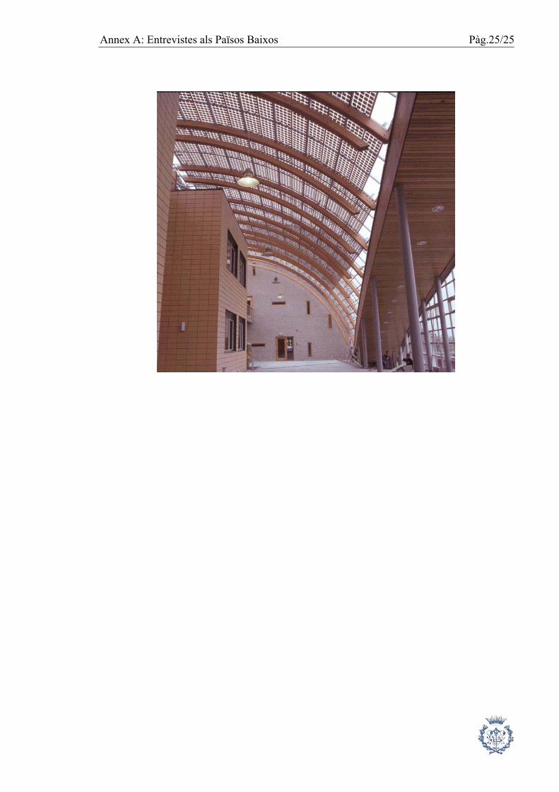
PICTURES OF THE 1 MW SOLAR PANEL PROJECT IN AMERSFOORT. Pictures taken from the web: http://www.oja-services.nl/iea-pvps/photos/index.htm

Pàg.24/25 Annex A: Entrevistes als Països Baixos
Annex A: Entrevistes als Països Baixos Pàg.25/25