enerdel presentation lmo/lto - us department of energy · enerdel presentation lmo/lto naoki ota...
TRANSCRIPT

Copyright © 2006 EnerDel, Inc., All Rights Reserved
EnerDel PresentationLMO/LTO
Naoki Ota
February 25, 2008
2
OutlineEnerDel Information and Resources
USABC Program SummaryHEV ProgramPHEV Program
Cell and System DesignCell test dataSystem architecture
Progress Highlight

EnerDel Mission & GoalMission
To be a leader in the development of renewable clean energy systems To ensure the reduction of oil consumption and green house gases for the benefit of our planetTo be the primary source of U.S. domestic supply of batteries for key strategic U.S. industries
Main GoalTo be the first lithium ion battery system manufacturer in the U.S. for automobile applications: Hybrid Electric Vehicles (HEV), Plug-In Hybrid Electric Vehicles (PHEV), and Electric Vehicles (EV). The core strategy to achieve this goal is the merger of our revolutionary lithium ion cell technology and automobile electronics technology through our own development effort and key strategic partnerships. 3
4
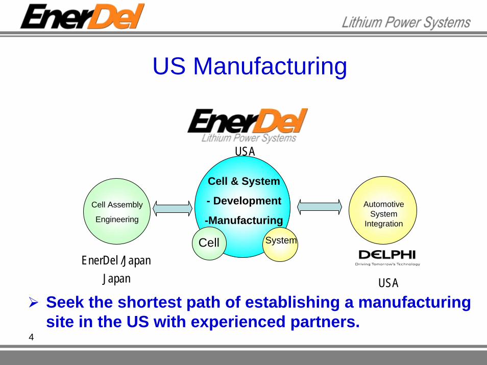
Cell Assembly
Engineering
Cell & System
- Development
-Manufacturing
Cell System
Automotive System
Integration
EnerDel /Japan
USA
USA
Japan
US Manufacturing
Seek the shortest path of establishing a manufacturing site in the US with experienced partners.

5
EnerDel Information Location
Indianapolis, IN
Full utility and infrastructure support for site
Facility built for the purpose of battery cell and pack manufacturing
Existing SpaceGeneral purpose plant area (~68,000 ft2)
Dry room facility (~6,000 ft2)Office area (~24,000 ft2)

6
Assembly and testing of packs
Full systems integration
EnerDel Resources
Manufacturing and testing cells

USABC Programs Summary
HEV ProgramPhase1 ( May/2006 to June/ 2007)
LMO / LTO Chemistry Performance StudyPhase2 ( October/2007 to March/ 2009)
LMO / LTO Full Size Cell Study (3 to 5Ah)Pack design study
PHEV ProgramPhase1 (February/2008 to August/2009)
High Voltage Cathode and ElectrolyteMake the best use of LTO anode.
7

8
Characteristics of LTO ChemistryAdvantages
High PowerLess impedance than graphite
Outstanding SafetyNo SEI layer
Remote risk of thermal runawayNo lithium dendritesStable active materials
Long LifeZero strain material
LTO ~ 0.2 % volume changeGraphite ~ 9% volume change
No lithium dendrites

9
Characteristics of LTO Chemistry, cont’dAdvantages, cont’d
Low temperature performanceLess impedance than graphiteMore electrolyte choices because of LTONo lithium dendrites
DisadvantagesLower Energy DensityLower Cell Voltage. (1.5V on negative)
Compared cells with graphite anode.….Much higher available energy and voltage than Ni-MH

10
High VoltageHigh voltage profile to couple with lithium titanate
Low Cost Low Cost Manganese Spinel powder cost is 3/4 of lithium iron phosphate, 1/2 of Lithium Nickel Cobalt Oxide, 1/3 of Lithium Cobalt OxideLarge worldwide reserves of Manganese
Power Capability Will allow for designing a small battery that can meet all the power requirements for HEV applications
Outstanding SafetyManganese Spinel release very small amount of oxygen under high temperature.
Manganese Spinel (Mn-Spinel/LMO) Advantages

11
EnerDel’s Chemistry for HEV ApplicationPositive Active Material: LiMn2O4- spinel (LMO)
LiMn2O4 ↔ Li1-xMn2O4 + xLi+ + xe-
Negative Active Material: Li4Ti5O12 (LTO)Li4Ti5O12 + xLi+ + xe- ↔ Li4+xTi5O12
1.5
1.8
2.1
2.4
2.7
3.0
0 20 40 60 80 100% of 1C Capacity (%)
Volta
ge (V
) 1C discharge30oC

12
Cell Design
PrismaticCase NeutralGood heat dissipationFlexible form-factor
CD Size A5 Size
Nominal Capacity 1.8 Ah 5 Ah
Nominal Voltage 2.5V 2.5 VDimensions(connections included) 145mm W, 130mm L, 5mm T 200mm W, 111mm L, 5.8mm T
Packaging Metal or Laminate Metal or Laminate

13
Rate Capability of 1.8 Ah Cells
High discharge efficiency for rates up to 50C.
1.4
1.6
1.8
2.0
2.2
2.4
2.6
2.8
3.0
0 10 20 30 40 50 60 70 80 90 100 110
% of 1C Capacity
Volta
ge(V
)
2C5C10C20C30C40C50C30oC
1C chargeVarying discharge rates
14
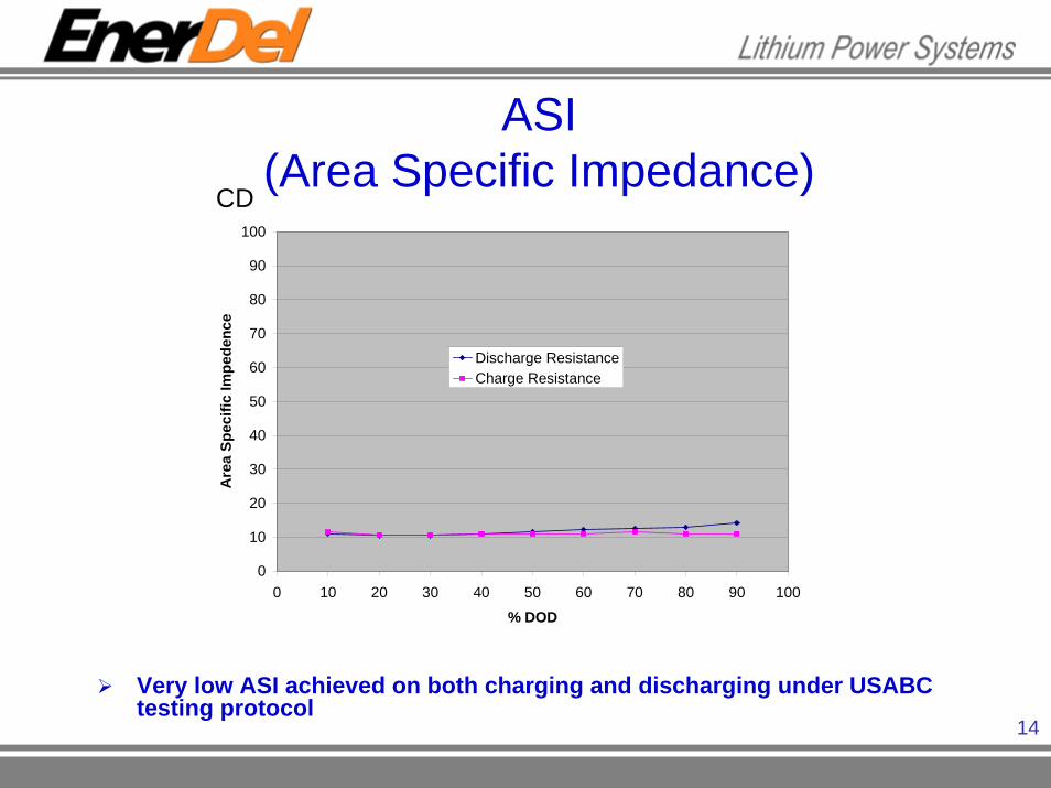
ASI(Area Specific Impedance)
Very low ASI achieved on both charging and discharging under USABC testing protocol
0
10
20
30
40
50
60
70
80
90
100
0 10 20 30 40 50 60 70 80 90 100
% DOD
Are
a Sp
ecifi
c Im
pede
nce
Discharge ResistanceCharge Resistance
CD

15
Power Capability
Gen2.0 cells show more power when comparing with the same BSF value.Gen2.0 has ~20% more power capability
0
10
20
30
40
50
60
0 20 40 60 80 100
Depth of Discharge (%)
Dis
char
ge P
ower
(kW
)
0
8
16
24
32
40
48
Reg
en P
ower
(kW
)
Discharge Gen1 BSF 127
Discharge Gen2 BSF 112
Regen Gen1 BSF 127
Regen Gen2 BSF 112
0
10
20
30
40
50
60
0 20 40 60 80 100
Depth of Discharge (%)
Dis
char
ge P
ower
(kW
)0
8
16
24
32
40
48
Reg
en P
ower
(kW
)
Discharge Gen1 BSF 127
Discharge Gen2 BSF 127
Regen Gen1 BSF 127
Regen Gen2 BSF 127
Gen1 BSF 127Gen2.0 BSF 112
Gen1 BSF 127Gen2.0 BSF 127

16
Low Temperature Performance
0.000.200.400.600.801.001.201.401.601.802.002.202.402.602.80
0 10 20 30 40 50 60 70 80Time (s)
Vol
tage
(V)
75% DOD50% DOD25% DOD
-30oC
Cold CrankingEquivalent to 5kW of power 1C Discharge
High power and full discharge capability at low temperatures.
0
20
40
60
80
100
-30°C 0°C 30°C 55°CTest Temperature
% o
f 30o C
Cap
acity

17
Energy Efficiency30oC, 30,000 cycles> 97% efficiency
0%
10%
20%
30%
40%
50%
60%
70%
80%
90%
100%
0 5000 10000 15000 20000 25000 30000
Cycle Number
Effic
ienc
y
No degradation in power capability after 30,000 energy efficiency cycles.

18
Safety: Nail penetration video
-1.0
0.0
1.0
2.0
3.0
4.0
5.0
6.0
0 2 4 6 8 10 12 14 16 18
Time (min)
Volta
ge (V
)
0
30
60
90
120
150
180
210
Tem
pera
ture
(C)
Cell Voltage
Cell Temperature
Room Temperature
Nail penetrates
10% Overcharged Cell

19
System Design Features
SafetySystem control redundancyUltra - low voltage assembly (non-lethal, easy maintenance)
Packaging EfficiencyStacking efficiency of prismatic cellsElimination of discrete wires for voltage / temperature sensing
Architectural FlexibilityModular design offers multiple arrangement configurations
Mechanical RobustnessDesigned for ease of assembly / error proofing features
Thermal managementDesign allows for air or liquid cooling
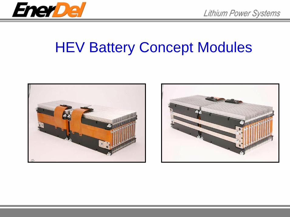
HEV Battery Concept Modules

Integration of EnerDelbattery system into an HEV (Prius)
21
Chemistry Energy Available Energy Maximum Power
Current Ni-MH 1.2kWh 0.3 kWh 40kWEnerDel LTO/LMO 1.0kWh 0.8 kWh 90kW

22
HEV Phase 1 Progress HighlightsEnerDel demonstrated the very high power capability of the LMO/LTO system in a scalable cell format (1.8 Ah).
The LMO/LTO system is able to provide high power across a broad range of usable energy and showed a good safety performance under preliminary test.
Achieved low temperature performance USABC requirements.

23
AcknowledgementsDOE/USABC team.
Argonne National Laboratory
Idaho National Laboratory