electrical service guidelines - mtemc.com service... · 6. a grounding electrode conductor (ground...
TRANSCRIPT
Electrical
Service
Guidelines
Middle Tennessee Electric Membership Corporation
Revised: Dec 31, 2018
Middle Tennessee Electric Membership Corporation

MTEMC's Electrical Service Guidelines
TABLE OF CONTENTS Changes in this Edition 3
Right-of-Way Clearance Guide 4
MTEMC Requirements 5
General Metering Requirements 6
Metering Visual Screening 7
ESG-400: 400 Amp Residential Metering 8
LBL-MDMB: Labeling for Multi-Metered Installations 9
ESG-1: Overhead Residential Service 10
ESG-2: Underground Residential Service 11
ESG-3: Underground Residential Service, Pad-Mount Transformer 12
ESG-4: Additional Meter on House 13
ESG-5: Member Pole Service, Standard Underground 14
ESG-6: Overhead Temporary Service 15
ESG-7: Underground Temporary Service 16
FSMC-2: Free Standing Meter Center 17
FSMC-3: Meter Pedestal 18
COM-6: Non Residential Metering with Multiple Customers and Service
Laterals from a Single Transformer 19
1S: Secondary Ditch Detail 20
2S: Secondary Ditch Detail 21
CTE-1: Current Transformer Enclosure Specifications 22
ESG-8: Security Lighting 23
ESG-9: Double Throw Switch Configuration of MTEMC Service and
Standby Generator 24
ESG-10: Generlink Meter Collar 25
ESG-11 Access Drive 26
MTEMC Offices Listed 27

MTEMC's Electrical Service Guidelines
Changes in this Edition 12/31/2018
General Specifications – Added note specifying point of demarcation requirements
General Metering – Revised language on labeling process for ganged meters
ESG-1– Added note to attach mast to structurally sound portion of building
ESG-2 – Added bedding and expansion coupling requirements at meter base
ESG-3 – Added bedding and expansion coupling requirements at meter base
ESG-8 – Updated LED description to reflect current offerings
ESG-11 – Added note to require driveway cuts where necessary
FSMC-2 – Added spacing note and guidelines on connections in a subdivision
FSMC-3 – Added spacing note and guidelines on connections in a subdivision

Right-of-Way Clearance Guide
12/31/2018
----40'--•
( ) ( 20' 20' 0 ---• MIN.- -MIN.------• ~
)
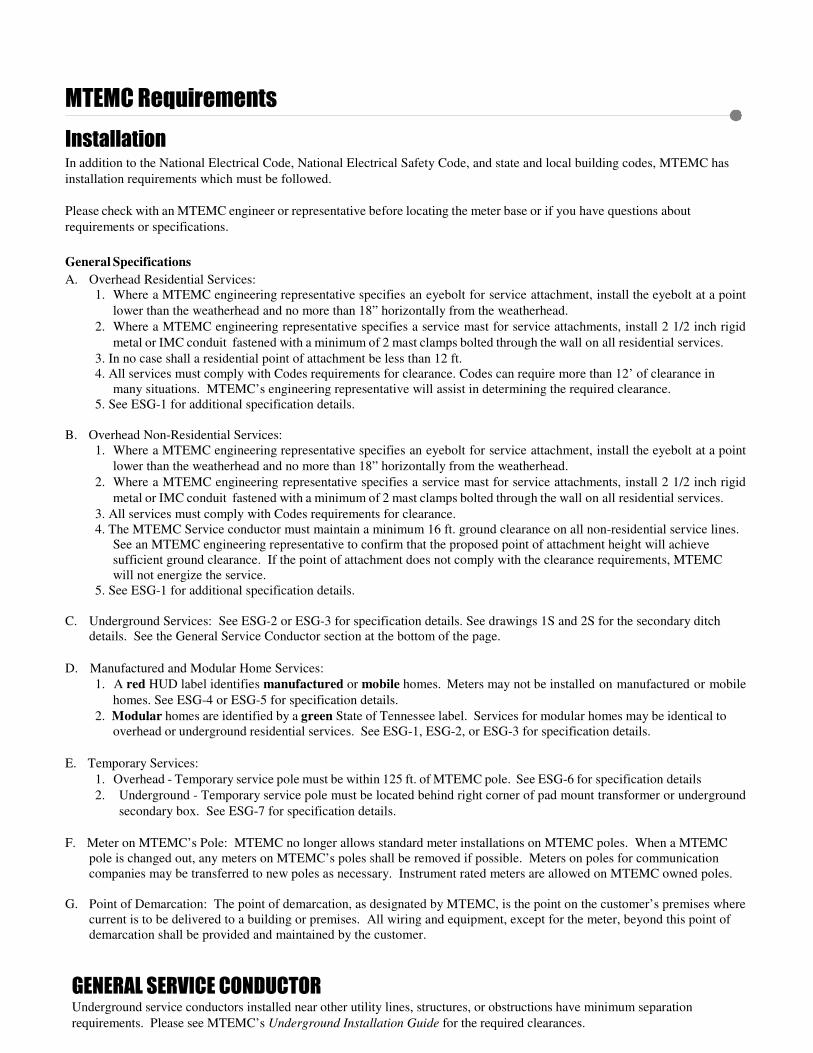
MTEMC Requirements
Installation In addition to the National Electrical Code, National Electrical Safety Code, and state and local building codes, MTEMC has
installation requirements which must be followed.
Please check with an MTEMC engineer or representative before locating the meter base or if you have questions about
requirements or specifications.
General Specifications
A. Overhead Residential Services:
1. Where a MTEMC engineering representative specifies an eyebolt for service attachment, install the eyebolt at a point
lower than the weatherhead and no more than 18” horizontally from the weatherhead.
2. Where a MTEMC engineering representative specifies a service mast for service attachments, install 2 1/2 inch rigid
metal or IMC conduit fastened with a minimum of 2 mast clamps bolted through the wall on all residential services.
3. In no case shall a residential point of attachment be less than 12 ft.
4. All services must comply with Codes requirements for clearance. Codes can require more than 12’ of clearance in
many situations. MTEMC’s engineering representative will assist in determining the required clearance.
5. See ESG-1 for additional specification details.
B. Overhead Non-Residential Services:
1. Where a MTEMC engineering representative specifies an eyebolt for service attachment, install the eyebolt at a point
lower than the weatherhead and no more than 18” horizontally from the weatherhead.
2. Where a MTEMC engineering representative specifies a service mast for service attachments, install 2 1/2 inch rigid
metal or IMC conduit fastened with a minimum of 2 mast clamps bolted through the wall on all residential services.
3. All services must comply with Codes requirements for clearance.
4. The MTEMC Service conductor must maintain a minimum 16 ft. ground clearance on all non-residential service lines.
See an MTEMC engineering representative to confirm that the proposed point of attachment height will achieve
sufficient ground clearance. If the point of attachment does not comply with the clearance requirements, MTEMC
will not energize the service.
5. See ESG-1 for additional specification details.
C. Underground Services: See ESG-2 or ESG-3 for specification details. See drawings 1S and 2S for the secondary ditch
details. See the General Service Conductor section at the bottom of the page.
D. Manufactured and Modular Home Services:
1. A red HUD label identifies manufactured or mobile homes. Meters may not be installed on manufactured or mobile
homes. See ESG-4 or ESG-5 for specification details.
2. Modular homes are identified by a green State of Tennessee label. Services for modular homes may be identical to
overhead or underground residential services. See ESG-1, ESG-2, or ESG-3 for specification details.
E. Temporary Services:
1. Overhead - Temporary service pole must be within 125 ft. of MTEMC pole. See ESG-6 for specification details
2. Underground - Temporary service pole must be located behind right corner of pad mount transformer or underground
secondary box. See ESG-7 for specification details.
F. Meter on MTEMC’s Pole: MTEMC no longer allows standard meter installations on MTEMC poles. When a MTEMC
pole is changed out, any meters on MTEMC’s poles shall be removed if possible. Meters on poles for communication
companies may be transferred to new poles as necessary. Instrument rated meters are allowed on MTEMC owned poles.
G. Point of Demarcation: The point of demarcation, as designated by MTEMC, is the point on the customer’s premises where
current is to be delivered to a building or premises. All wiring and equipment, except for the meter, beyond this point of
demarcation shall be provided and maintained by the customer.
GENERAL SERVICE CONDUCTOR Underground service conductors installed near other utility lines, structures, or obstructions have minimum separation
requirements. Please see MTEMC’s Underground Installation Guide for the required clearances.

GENERAL METERING REQUIREMENTS
Non Residential- anything other than a single family dwelling
1. All meter sockets used in MTEMC’s service area must be one of the MTEMC approved meter sockets (bases). All
sockets and hubs shall be furnished and installed by the member.
2. All meter sockets must be mounted between 4 and 6 feet above final grade.
3. All meter sockets shall be mounted outdoors in a location that is easily accessible for MTEMC personnel. Any
variation must be approved in writing by a MTEMC engineering representative.
4. The maximum allowable service wire to connect to MTEMC padmount transformer is 750MCM. The maximum
allowable service wire to connect in UG pull box is 500 MCM. For single phase services of 800 amps or less,
MTEMC will pull the service wire from the transformer/pull box to the metering point.
5. For multiple services feeding from the same transformer a non-fused safety switch with provisions for an MTEMC
padlock shall be installed on the source side each 277/480V self contained (400 Amps and smaller) meter and each
instrument metering installation (larger than 400 Amps). 120/208V and 120/240V self contained (400 Amps and
smaller) metering shall require a disconnect adjacent to the meter on the exterior of the building.
6. If more than one metering installation is fed from the same transformer, a disconnect shall be installed on the source
side of all troughs and ganged metering installations.
7. If a service conductor feeds several meters (gang meter socket, metering trough, etc.), each meter, disconnect, and
main electrical panel inside each unit shall be labeled with identification numbers (address). These numbers shall be on
a stamped or engraved brass or stainless steel label and attached with 2 or more rivets. They should be in a readily
visible location on both the meter and disconnect. Labels shall be furnished and installed by the customer.
Residential- single family dwelling
1. All meter sockets used in MTEMC’s service area must be one of the MTEMC approved meter sockets (bases). All
sockets and hubs shall be furnished and installed by the member.
2. All meter sockets must be mounted between 4 and 6 feet above final grade.
3. All meter sockets shall be mounted outdoors in a location that is easily accessible for MTEMC personnel. Any
variation must be approved in writing by a MTEMC engineering representative.
4. The maximum allowable service wire to connect to MTEMC padmount transformer is 750MCM. The maximum
allowable service wire to connect in UG pull box is 500 MCM. For single phase services of 800 amps or less,
MTEMC will pull the service wire from the transformer/pull box to the metering point.
5. Meter base will not be located on or under porches, decks or carports. The meter base shall be located as close to
MTEMC’s transformer/pull box as possible. If the distribution panel is not located in immediate vicinity of meter, a
weatherproof disconnect may be required; refer to National Electric Code.
6. A grounding electrode conductor (ground wire) of a minimum of No. 4 copper or larger shall be run unspliced from
a lug in the meter base to a driven grounding electrode (ground rod).
An 8 ft. driven grounding electrode (ground rod) bonded to grounding electrode conductor (ground wire) with
clamp suitable for direct soil burial will be installed below final grade.
12/31/2018

METERING VISUAL SCREENING
ELECTRICAL METER ROOMs WILL NOT BE ALLOWED
SHIELDING THE VIEW OF METERS
Shielding the view of meters with walls is allowed with written approval of MTEMC. This must be obtained PRIOR TO CONSTRUCTION.
A drawing showing the physical arrangement of all meters must be provided to MTEMC prior to obtaining approval.
If physical space available requires that meter bases be installed in a vertical arrangement, the highest meter shall be not more than six (6) feet above the floor to the center of the glass cover, and the lowest meter shall not be less than three (3) feet from the floor to the center of the glass cover.
The meters shall be located where they will be readily accessible at ALL times for emergencies, meter reading, testing and other maintenance purposes. All meter locations shall meet all NEC requirements regarding but not limited to access, egress and clear space around the meter. There shall be a minimum of three and one half (3.5) feet working space between the front of the meter socket and any walls or other obstructions. The meters shall be located on an exterior wall of the building.
There shall be no roof covering the meter space. There shall be no door, gate, etc. at the entry of the space.
Access is a critical issue for MTEMC related to its facilities. If access to the meter space is not possible due to some obstruction, MTEMC reserves the right to remove the obstruction and is not responsible for any damages to those or for reinstalling them in the future.
Meter spaces shall not be used for other purposes such as storage closets, maintenance areas, etc.
Meter bases shall be surface mounted. Flush mounted or recessed meter installations are not acceptable.
If the acceptance of a meter space by MTEMC requires additional communication infrastructure related to the reading of the meters by the MTEMC AMI system, the additional costs will be the responsibility of the customer.
12/31/2018

12/31/2018
0 400(320) Amp Self Contained
Customer Disconnect
Meter Socket 1-----------------1
\ MTEMC PREFERRED METHOD
3" sch 80 conduit by customer
Customer Disconnect
Alternate Location
0 400(320) Amp Self Contained
1-------1 Meter Socket 1-------1
I I
I I I I I
''/ 3" sch 80 conduit by customer
MTEMC ALTERNATE METHOD NOTE:
Customer Disconnect
Customer Disconnect
SEE MTEMC ENGINEERING REPRESENTATIVE FOR APPROVAL
MIDDLE
TENNESSEE
ELECTRIC
MEMBERSHIP
CoRPORATION
400 AMP RESIDENTIAL
METERING When Disconnects are Required
REVISED: 10-05-16
DES.: ~ APPR.: __ DRAWN: RDR
ESG-400

12/31/2018
Fig. (GANG METER) DISCONNECT
8 8
Fig. 2 (TROUGH METER)
0 D 0 D /',- I A1 I I A1 I /',- I A2 I I A2 I
_)) MIDDLE TENNESSEE ELECTRIC MEMBERSHIP CORPORATION REQUIRES ALL LABELING ON METER SOCKETS TO MEET THE FOLLOWING SPECIFICATIONS:
1. LABELS SHALL BE BRASS OR STAINLESS STEEL. 2. IDENTIFICATION NUMBERS AND LETTERS SHALL BE STAMPED OR ENGRAVED. 3. LABELS SHALL BE FASTENED WITH RIVETS. 4. FOR GANG METER SOCKETS, LABEL SHALL BE PLACED ON ALL OF THE DISCONNECT PORTIONS OF THE METER BASE
(SEE FIG. 1 ). GRAYBAR NOTE: ANY OTHER ASSOCIATED DISCONNECTS ON THE LOAD SIDE OF THE METER BASE SHALL ALSO BE LABELED.
5. FOR TROUGH APPLICATIONS, LABEL SHALL BE PLACED IN A READILY VISIBLE LOCATION FOR BOTH THE DISCONNECT AND THE METER COVER (SEE FIG. 2).
6. THE MAIN ELECTRICAL PANEL INSIDE EACH UNIT SHALL BE MARKED WITH THE CORRESPONDING UNIT NUMBER. THE MARKING SHALL BE PERMANENT IN NATURE, WITH THE IDENTIFYING LABEL AFFIXED INSIDE THE PANEL.
7. THE MAIN ENTIRY DOOR TO THE UNIT SHALL BE MARKED WITH IDENTIFYING LABEL AFFIXED TO THE DOOR OR AREA ADJACENT TO THE ENTIRANCE IN PLAIN VIEW.
8. METERS WILL NOT BE SET AND ENERGIZED UNTIL ALL LABELING IS COMPLETED FOR THE CORRESPONDING SERVICE PULL.
9. REFER TO DRAWING COM-6 FOR ADDITIONAL SERVICE REQUIREMENTS. THESE LABELS CAN BE PURCHASED FROM TROPHY SHOPS OR ANY BUSINESS WHICH SUPPLIES ENGRAVED DOG TAGS.
MIDDLE
TENNESSEE
ELECTRIC MEMBERSHIP
CoRPORATION
LABELING FOR MULTI- METERED INSTALLATIONS
REVISED: Dec. 27, 201a
DES.: ~ APPR.: __ DRAWN: RDR
LBL-MDMB

12/31/2018
225 amp or less
I I I
Service entrance conductors see note 3.
"'--- Raceway see note 4.
Conduit straps see note 4.
I Un spliced 1-------- ground wire I General Metering I I I
'I '- Ground rod ~ and clamp
General Metering
Additional Stud
Exterior Wall
Service entrance conductors ~ see note 3. '\_
Mast clamps see note 7.
I I I
Service mast / see note 7.
I Un spliced 1-------- ground wire
inished Interior Wall
Stud
I see General Metering I I I
'I '- Ground rod ~ and clamp
see General Metering
Additional Stud
Exterior Wall
1.
2.
3.
Weatherhead must be above point of service drop attachment.
An eyebolt (5/8" minimum) and related hardware will be furnished and installed by the member. The eyebolt must pass through a plate consisting of two 2"x6"s doubled together similar to a window header spanning two or more wall studs and secured to the studs with a minimum of two four-inch lag screws in each end of the 2"x6" assembly. If the eyebolt is installed outside a finished wall, such that the nut and washer protruding past the doubled 2"x6"s into the interior of the structure will hinder finishing of the interior wall, the alternate method may be used. This consists of a single 2"x6" equal in length to a wall stud, turned 90 degrees, nailed to a wall stud along its entire length, and backed by an additional stud situated normally and nailed to the 90 degree 2"x6". The 2"x6" shall be nailed in with a minimum of 5 nails per side, with no more than 14" between nails along its length. This assembly will provide a cavity for the nut and washer assembly to clear the stud side of the interior wall wallboard. See "Alternate Eyebolt Detail". The eyebolt must be below, and within 18 inches of weatherhead and minimum of 12 feet above final grade. Point of service drop attachment will be of sufficient height to provide minimum clearances as specified by the National Electrical Code (NEC) and the National Electric Safety Code (NESC).
Service entrance conductor must extend 36" out of the weatherhead.
4. Rigid conduit, IMC, EMT, or SC. 40 electrical PVC with rain-tight couplings and connectors may be used as service entrance conductor raceway. Service entrance raceways will be secured with a minimum of 2 conduit straps, the lower being within 3 ft. of top of meter base.
5. Where a mast riser is used, weatherhead will be a minimum of 36 in. above roof. If weatherhead is more than 42 in. above roof, a guy wire with eyebolt through rafter is required.
6. Service clevis assembly will be furnished and installed by MTEMC.
7. Service mast will be a minimum of 2 ½" rigid metal conduit secured with a mInImum of 2 mast clamps fastened to a structural part of the building (sheathing on a vinyl sided
house is not sufficient) with ½" clamp bolts; the lower being within 3 feet of top of the meter base and the upper being within 3 feet of where the mast passes through the roof. Sections of conduit must be connected using threaded couplings, and the threaded coupling must be located between the clamps.
8. See General Metering Requirements for additional metering information
2-2"x6"
Stud Overhead Residential Service
DATE (Rotated 90°)
ALTERNATE EYEBOLT DETAIL PREFERRED EYEBOLT DETAIL SCALE:_--=N.,_,. T=.S=·---1
STAKED BY: __ __,
DRAWN BY: RDR
CHECKED BY: ILG
Dec. 27, 2018
ESG-1 SHEET--~1~_ ....
OF_l_ SHEETS

12/31/2018
225 amp or less
Materials furnished by
MTEMC see note 1.
/
For all connections use long coupling, integral belled end conduit.
Ditch see note 2.
Raceway see note 3.
Where service rating exceeds 225 amp member
must furnish and install this type (or similar U.L. listed) connector on line and load sides of meter base.
Meter base Un spliced
see note 4 ~ and General
Metering /
ground wire see General Metering
'1 I
2 Conduit
Service conductors see MTEMC Requirements
General Service conductor
I I I I I I I I I
Ground rod and clamp see
General Metering
*Be sure to call Tennessee One Call before digging or opening ditches: 1-800-351-1111 or 811
1. MTEMC will furnish and install the following materials at the service pole:
A. Conduit, to include all related hardware
B. Service conductor from transformer to meter base
C. Where junction box (not shown) is present at service pole, see a MTEMC engineering representative for specifications.
2. Member will open ditch from service pole or junction box to meter location with the following specifications:
A. Where ditch length will exceed 250 ft. see MTEMC engineering representative prior to opening ditch.
B. Depth sufficient to bed conduit with service conductors 24 in. below final grade.
C. Where impractical to obtain 24 in. depth, see a MTEMC engineering representative.
D. Member will backfill ditch after inspection by MTEMC - 24 hr. notice required (call 877-886-8362 or visit www.MTEMC.com to fill out an online request)
3. Continuous raceway from service pole base to meter base will be furnished and installed by member to the following specifications:
4.
A. Conduit size is to be 3 inch with appropriate fittings and/or bushings as required. For all conduit connections use long, integral belled end conduit.
B. Raceway between elbows is to be schedule 40 electrical PVC or schedule 80 electrical PVC.
C. Elbows are to be schedule 80 electrical PVC with a minimum sweeping radius of 24 inches.
D. Conduit extending from meter base to one foot below grade is to be schedule 80 electrical PVC.
E. A polyvinyl, non rot or mildew proof, pull string with a minimum breaking strength of 200 pounds is to be installed inside the raceway.
F. Under certain loading and/or density conditions, an alternate sized conduit may be used with the approval of MTEMC district office engineering representative.
G. 2 Conduit Straps: Place one conduit strap 12" below meter base and place second conduit strap 12" above ground.
H. Conduit shall be placed on firm soil throughout the entire run. The bedding below the conduit near the meter base shall be sufficient to prevent settling. Should MTEMC deem bedding to be insufficient, a 3" PVC expansion coupling shall be required at the meter base. The expansion sleeve shall be located between the two conduit straps as referenced in Note 3G.
A MTEMC approved meter base of proper size and type shall be furnished and installed by the member. See General Metering Requirements for additional metering information.
POLE~ CONDUIT
"" Underground Residential
Service
'-._TELEPHONE OR CABLES
TOP VIEW
CATV SCALE:_~N=·~T=.S=·---1
STAKED BY=-----t
DRAWN BY: RDR
CHECKED BY: ILG
DATE
Dec. 27, 2018
ESG-2 SHEET--~1--~
OF_l_ SHEETS

12/31/2018
Caution!
Before digging, Call TN-1-CALL (1-800-351-1111 or
811) to determine location of underground facilities. Hand-dig
ditch within 5 feet of transformer.
Materials furnished by
MTEMC see note 1.
I I I 1 Ditch I see note 2. I L---
Raceway see note 3.
Where service rating exceeds 225 amp member
must furnish and install this type (or similar U.L. listed) connector on line and load sides of meter base.
Meter base ~ see note 4 and '
General Metering
2 Conduit straps see note 3.G.
/
Unspliced ground wire see General
Metering. -~ I
I Ground rod and I clamp see I General Metering I I I
Service conductors
For all connections use long coupling, intergral belled end conduit
see MTEMC requirements. -General Service Conductor
*Be sure to call Tennessee One Call before digging or opening ditches: 1-800-351-1111 or 811
1. MTEMC will furnish and install the following materials:
2.
A. Service conductor from transformer to meter base
B. Where junction box (not shown) is present, see a MTEMC engineering representative for specifications.
Member will open ditch from transformer to meter location with the following specifications:
A. Where ditch length will exceed 250 ft. see a MTEMC engineering representative prior to opening ditch.
B. Hand-dig ditch when within 5 ft. of transformer.
C. Depth sufficient to bed conduit with service conductors 24 in. below final grade.
D. Where impractical to obtain 24 in. depth, see a MTEMC engineering representative.
E. Member will backfill ditch after inspection by MTEMC - 24 hr. notice required (call 877-886-8362 or visit www.MTEMC.com to fill out an online request)
F. Before working with the transformer, notify MTEMC so that MTEMC representation can be present.
Continuous raceway from transformer to meter base will be furnished and installed by member to the following specifications:
A. Conduit size is to be 3 inch as specified below with appropriate fittings and/or bushings as required. For all conduit connections use long, integral belled end conduit.
B. Raceway between elbows is to be either schedule 40 electrical PVC or schedule 80 electrical PVC conduit.
C. Elbows are to be schedule 80 electrical PVC with a minimum sweeping radius of 24 inches.
D. Conduit extending from meter base to one foot below grade is to be schedule 80 electrical PVC.
E. A polyvinyl, non rot or mildew proof, pull string with a minimum breaking strength of 200 pounds is to be installed inside the raceway.
F. Under certain loading and/or density conditions, an alternate sized conduit may be used with the approval of MTEMC district office engineering representative.
G. 2 Conduit straps: Place one conduit strap 12" below meter base and place second strap 12" above ground.
H. Conduit shall be placed on firm soil throughout the entire run. The bedding below the conduit near the meter base shall be sufficient to prevent settling. Should MTEMC deem bedding to be insufficient, a 3"PVC expansion coupling shall be required at the meter base. The expansion sleeve shall be located between the two conduit straps as referenced in Note 3G.
Underground Residential Service
4. A MTEMC approved meter base of proper size and type shall be furnished and installed by the member. See General Metering Requirements for additional metering information.
Pad-mount transformer
SCALE:_~N~. T=.S=·~---i
STAKED BY: -------1
DRA WN BY: RDR
CHECKED BY: ILG
ESG-3 DATE
Dec. 27, 2018
SHEET--~l~----11
OF_l_ SHEETS

12/31/2018
Raceway and
Conduit Straps
see note 1.
Meter base see 1 note 2 and General Metering
Raceway (below meter)
see note 4.
Points of attachment
Service entrance conductors see note 4
and MTEMC Requirements, General service conductor
Tennessee Wiring Inspection Decal
Required
Raceway (below structure)
see note 4.
Notes:
An external building can sometimes be served efficiently by installing the new meter beside an existing meter on a house or building. While this usually results in lower construction costs, members are subject to additional charges if existing service drop conductor size or transformer size must be increased.
1 .
2.
3.
4.
5.
Maximum separation between weatherheads shall be no more than 2 ft. Additional specifications for weatherheads, points of attachment, clearances, service entrance conductors, conduit, etc., are identical to Overhead Residential Service.
A MTEMC approved meter base and hub of proper size and type shall be furnished and installed by the member. See General Metering Requirements for additional metering information.
If connecting to a manufactured home a weatherproof, UL listed, multi-circuit disconnect is to be located within 30 feet of the manufactured home. Whether located below meter base on member's pole or on stub, in no case will disconnect be less than 2 feet above grade.
For information about conductors, conduit and grounding, refer to National Electrical Code
2 Conduit Straps: Place one conduit strap 12" below disconnect and place second strap 12" above ground.
Additional meter on house
DATE SCALE:_~N=·=T-=S•~--,
STAKED BY=-------t
DRAWN BY: RDR
CHECKED BY: ILG
May 23, 2013
ESG-4 SHEET 1
OF_l_ SHEETS

12/31/2018
Weatherhead see note 3.
Materials furnished
by MTEMC see note 1.
Unspliced ground wire see General
Metering
L_
Ground rod and l clamp see
General Metering
Service entrance conductors see note 4.
Conduit straps see note 5.
Service raceway see note 5.
Meter base see note 6 and General
Metering
Raceway (below meter)
see note 8.
straps see note 10.
Underground service entrance conductors
see note 8 and MTEMC Requirements-General
Service Conductor
Metering location to be confirmed
by MTEMC engineering prior to installation.
Tennessee Wiring Inspection Decal
Required
Raceway (below structure)
see note 8.
Notes:
1. Member poles allowed for municipal purposes only. ( eg. TDOT traffic cameras, city traffic signalization, school crossing signalization, or similar uses as approved by MTEMC engineering).
2. For residential purposes, the member shall install an underground service to a free standing meter center, either a uni-strut (MTEMC drawing FSMC-2) or a cabinet type (MTEMC drawing FSMC-3).
3. Where meter service will be located on Member's pole, MTEMC will furnish and install: A. service drop conductor from service pole to member's pole B. guy wires and anchors as required (minimum 10 ft. separation between pole and anchor).
4. Location and height of member pole to be determined by a MTEMC engineering representative. Member's pole will be a treated utility pole set a minimum of 5 feet in the ground.
5. The service drop must be between 6" and 12" from the top of the pole. The weatherhead must be within 12" from the service drop, and it can be above or below the service drop.
6. Service entrance conductor must extend 36" out of the weatherhead. 7. Rigid conduit, IMC, EMT, or SC. 80 electrical PVC with rain-tight couplings and
connectors may be used as service entrance conductor raceway. Service entrance raceways will be secured with a minimum of 2 conduit straps, the lower being within 3 ft. of top of meter base.
8. A MTEMC approved meter base and hub of proper size and type shall be furnished and installed by the member.
9. Whether located below meter base on member's pole or on stub, in no case will disconnect be less than 2 feet above grade. If spacer block in necessary behind meter base or disconnect, use metal brackets.
10. For information about conductors, conduit and grounding, refer to National Electrical Code.
11. See General Metering Requirements for additional metering information. 12. 2 Conduit Straps: Place one conduit strap 12" below disconnect and place second
strap 12" above ground. 13. In the case of an existing member pole replacement, if the old member pole is
used for non-municipal purposes, the re-build shall incorporate a freestanding meter center or cabinet type base as shown in MTEMC drawing FSMC-2 or FSMC-3.
Member Pole Service For Municipal Purposes Only
SCALE:_--=N,_,. T=.S=·---1
STAKED BY: __ ___,
DRAWN BY: RDR
CHECKED BY: ILG
ESG-5 REVISED:
Jan. 8, 2018
SHEET __ ~l~---1
OF_l_ SHEETS

12/31/2018
Receptacles See note 11.
I 50 AMP I
240V 100 amps single phase or less. For temporary services larger than 100 amps, see your local MTEMC Engineering Department.
TRIP
OFF
Push to test
Un spliced Ground wire See General Metering
Ground rod and clamp ~ See General Metering. ""
.,,, I .,,, I I
I I I I I I I I I I I I I I I I u
Weatherhead See note 5.
Service entrance conductors
See note 8.
Clearances See note 7.
Eyebolt, deadend, insulator, pigtail
See note 6.
Meter base See General Metering
'-.. Temporary ~ service pole
See notes 1 & 2.
Service panel See General
Metering.
Note: All materials furnished and installed by contractor.
Notes:
MTEMC will provide service to temporaries that have passed state wiring inspection at present site and meet the following wiring and construction standards:
1. Service equipment and meter base securely fastened to a 2 in. metal pipe, 4x4 post, or 2x8 board, and set in the ground at a minimum depth of 2 ft.
2. Temporaries will not be attached to trees or to MTEMC poles.
3.
4.
5.
6.
7.
Each temporary will have a minimum of 4 braces; 2 of which will brace against pull of service drop. Braces will be attached at least 9 ft high on pole and extend at least 6 ft from pole to base.
Temporary service will not be located more than 125 ft. from existing MTEMC service pole. Consult with a MTEMC engineering representative for specific location, if necessary.
Weatherhead must be above point of service drop attachment.
The contractor will furnish and install a 5/8" eyebolt, preformed dead end, insulator, and Minimum No. 4 aluminum triplex pigtail.
Point of service drop attachment will be of sufficient height to provide a minimum clearance of 12 ft.
8. Service entrance conductors should extend from weatherhead to grade after connecting to pigtail and attaching pre-formed dead end to 5/8" eyebolt.
9. Service entrance raceway may be rigid conduit, EMT, IMC, or schedule 40 electrical PVC with rain-tight couplings and connectors. Service entrance cable with weatherhead may also be used.
10. A weatherproof, UL listed temporary service panel will be located below MTEMC approved meter base. In no case will the bottom of the panel be less than 2 feet above grade.
11. All receptacles will have ground fault protection for personnel unless otherwise exempted by the NEC.
12. If a temporary service has been left in place for 3 years it must be removed and a permanent service must be installed.
13. See General Metering Requirements for additional metering information.
Overhead Temporary Service
SCALE:_-=N.,_,. T=.S=·---1
STAKED BY:------<
DRAWN BY: RDR
CHECKED BY: ILG
ESG-6 DATE
May 15, 2013
SHEET--~1~--
OF_l_ SHEETS
12/31/2018
Temporary service post 7 see note 1.
Top View
Location ~~ see note 2. ~ r' (\
24~0~!ep ~ 2 t ft. /}
i ha~le 1rr==== see note 4
Lot A Lot B
Lot B
G ........,~-...,.........~ Meter base
see General Metering.
~ Service panel see note 5.
I r Unspliced Ground Wire ,-, to Ground Rod I " see General Metering I I I I I
I I I I
Road
Lot A TRIP
240V 100 Amps Single Phase or less
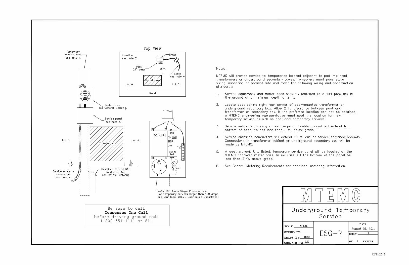
Notes:
MTEMC will provide service to temporaries located adjacent to pad-mounted transformers or underground secondary boxes. Temporary must pass state wiring inspection at present site and meet the following wiring and construction standards:
1.
2.
Service equipment and meter base securely fastened to a 4x4 post set in the ground at a minimum depth of 2 ft .
Locate post behind right rear corner of pad-mounted transformer or underground secondary box. Allow 2 ft. clearance between post and transformer or secondary box. If the preferred location can not be obtained, a MTEMC engineering representative must spot the location for new temporary service as well as additional temporary services.
3. Service entrance raceway of weatherproof flexible conduit will extend from bottom of panel to not less than 1 ft. below grade.
4. Service entrance conductors will extend 10 ft. out of service entrance raceway. Connections in transformer cabinet or underground secondary box will be made by MTEMC.
5. A weatherproof, U.L. listed, temporary service panel will be located at the MTEMC approved meter base. In no case will the bottom of the panel be less than 2 ft. above grade.
6. See General Metering Requirements for additional metering information.
I I _____ I For temporary services larger than 100 amps see your local MTEMC Engineering Department.
Be sure to call Tennessee One Call
before driving ground rods 1-800-351-1111 or 811
Underground Temporary Service
SCALE:_~N~. T=.S=·~__.
STAKED BY: ------t
DRA WN BY: RDR
CHECKED BY: ILG
ESG-7
DATE
August 26, 2011
SHEET 1
0F_l_ SHEETS
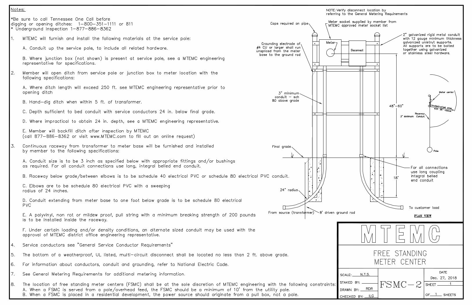
Notes:
*Be sure to call Tennessee One Call before digging or opening ditches: 1-800-351-1111 or 811 * Underground Inspection 1-877-886-8362
1. MTEMC will furnish and install the following materials at the service pole:
A. Conduit up the service pole, to include all related hardware.
B. Where junction box (not shown) is present at service pole, see a MTEMC engineering representative for specifications.
2. Member will open ditch from service pole or junction box to meter location with the following specifications:
3.
A. Where ditch length will exceed 250 ft. see MTEMC engineering representative prior to opening ditch
B. Hand-dig ditch when within 5 ft. of transformer.
C. Depth sufficient to bed conduit with service conductors 24 in. below final grade.
D. Where impractical to obtain 24 in. depth, see a MTEMC engineering representative.
E. Member will backfill ditch after inspection by MTEMC ( call 877-886-8362 or visit www.MTEMC.com to fill out an on line request)
Continuous raceway from transformer to meter base will be furnished and installed by member to the following specifications:
A. Conduit size is to be 3 inch as specified below with appropriate fittings and/or bushings as required. For all conduit connections use long, integral belled end conduit.
Caps required on
Grounding electrode of #4 CU or larger shall run unspliced from the meter
base to the ground rod
3" minimum conduit - sch
80 above grade
Final grade
B. Raceway below grade/between elbows is to be schedule 40 electrical PVC or schedule 80 electrical PVC conduit.
C. Elbows are to be schedule 80 electrical PVC with a sweeping radius of 24 inches.
. . 4,
NOTE: Verify disconnect location by referring to the General Metering Requirements
Meter socket supplied by member from MTEMC approved meter socket list
1/ 2" galvanized rigid metal conduit with 12 gauge minimum thickness
1--_,------,._-1..._--1 galvanized unistrut supports. f-----.---i All supports are to be bolted
Disconnect together using galvanized or stainless steel hardware.
48"-60"
18"
Pole
For all connections use long coupling integral belled end conduit
D. Conduit extending from meter base to one foot below grade is to be schedule 80 electrical PVC
E. A polyvinyl, non rot or mildew proof, pull string with a minimum breaking strength of 200 pounds is to be installed inside the raceway.
From source (transfo ~8' driven ground rod
To customer load
4.
5.
6.
7.
8.
PLAN VIEW
F. Under certain loading and/or density conditions, an alternate sized conduit may be used with the approval of MTEMC district office engineering representative.
Service conductors see "General Service Conductor Requirements"
The bottom of a weatherproof, UL listed, multi-circuit disconnect shall be located no less than 2 ft. above grade.
For information about conductors, conduit and grounding, refer to National Electric Code.
See General Metering Requirements for additional metering information.
FREE STANDING METER CENTER
SCALE: -~N~.T~.S=·----1 DATE
Dec. 27, 2018
The location of free standing meter centers (FSMC) shall be at the sole discretion of MTEMC engineering with the following constraints: STAKED BY: __ ____, F SMC - 2 SHEET--~-----
A. When a FSMC is served from a pole/overhead feed, the FSMC should be a minimum of 1 O' from the utility pole. DRAWN BY: RDR
B. When a FSMC is placed in a residential development, the power source should originate from a pull box, not a pole. CHECKED BY: ILG OF_,___ SHEETS

Notes:
*Be sure to call Tennessee One Call before digging or opening ditches: 1-800-351-1111 or 811 * Underground Inspection 1-877-886-8362
1.
2.
3.
MTEMC will furnish and install the following materials at the service pole:
A. Conduit up the service pole, to include all related hardware.
B. Service conductor from transformer to meter pedestal.
C. Where junction box (not shown) is present at service pole, see a MTEMC engineering representative for specifications.
Member will open ditch from service pole or junction box to meter pedestal with the following specifications:
A. Where ditch length will exceed 250 ft. see MTEMC engineering representative prior to opening ditch
B. Hand-dig ditch when within 5 ft. of transformer.
C. Depth sufficient to bed conduit with service conductors 24 in. below final grade.
D. Where impractical to obtain 24 in. depth, see a MTEMC engineering representative.
E. Member will backfill ditch after inspection by MTEMC (call 877-886-8362 or visit www.MTEMC.com to fill out an online request)
Continuous raceway from transformer to meter pedestal will be furnished and installed by member to the following specifications:
A. Conduit size is to be 3 inch as specified below with appropriate fittings and/or bushings as required. For all conduit connections use long, integral belled end conduit.
NOTE: Verify disconnect requirements by referring to
General Metering Requirements
Final grade
B. Raceway below grade/between elbows is to be schedule 40 electrical PVC or schedule 80 electrical PVC conduit.
C. Elbows are to be either schedule 80 electrical PVC with a sweeping radius of 24 inches.
D. Raceway above grade to one foot below grade is to be schedule 80 electrical PVC.
E. A polyvinyl, non rot or mildew proof, pull string with a minimum breaking strength of 200 pounds is to be installed inside the raceway.
F. Under certain loading and/or density conditions, an alternate sized conduit may be used with the approval of MTEMC district office engineering representative.
From source (transformer)
Concrete base to be 19" H minimum, extend a minimum of 6" beyond the enclosure, and 4" - 6" above final grade.
Foundation shall be fiber reinforced concrete. Edge shall be a 1'' chamfer.
Service conductors see "General Service Conductor Requirements"
For information about conductors, conduit and grounding, refer to National Electric Code.
See General Metering Requirements for additional metering information.
. ... . . ·'·.
4.
5.
6.
7.
8.
9. The location of free standing meter centers (FSMC) shall be at the sole discretion of MTEMC engineering with the following constraints: A. When a FSMC is served from a pole/overhead feed, the FSMC should be a minimum of 1 O' from the utility pole. B. When a FSMC is placed in a residential development, the power source should originate from a pull box, not a pole.
Disconnect
, ... •, ·.: : ···.:.,: · .. -~ .. -:•
. :, .... · · .. :·. ·.· ·:_. .. •,,
·.·. ..... ·.:. :· ...... z •
.. .. ·' ... \.,:. ··.:··
·: .. •, ':" . ,\ .· ;-
. ·:
: ......
Meter socket supplied by member from MTEMC approved meter socket list
NOTE: 3' radius unobstructed area required around meter pedestal
Grounding electrode of #4 CU or larger shall run unspliced from the meter
base to the ground rod
4" -6" above final grade
~-- For all connections use long coupling integral belled end conduit
To customer load
8' driven ground rod PLAN VIEW
SCALE: N.T.S.
METER PEDESTAL
DATE
DEC. 27, 2018
STAKED BY: ----I F s MC - 3 SHEET -~----
DRAWN BY: AHS
CHECKED BY: AHS OF _ _,___ SHEETS

12/31/2018
n ~ = ~ -:::l c-+--= ~
(SEE NOTE 8) ~~L_ Showa foe o,ert,eod sec,ke / ........
NOTES:
SERVICE ENTRANCE #1
Q
CURRENT TRANSFORtAER CABINET FURNISHED AND INSTAU.ED BY THE \
CUSTOME~:.n! ~:f~SION FOR TO CUSTOMER LOAD
CURRENT TRANSFORMER RATED \ METER SOCKET FURNISHED AND ~-L->--~
INSTALLED BY CUSTOMER C.T.
CABINET
0 [IQ]]
1" CONDUIT FURNISHED AND INSTALLED BY CUSTOMER J J (SEE NOTE 7)
CUSTOMER TO FURNISH AND INSTALL __/ CONDUIT AND SERVICE LATERALS
I I I I I I I I I I I I I I I I I I
/ ' / '
/ ' / ~
/ ~
/ \ --- \
INSTALL MTEMC SAFETY SWITCH ON SOURCE SIDE OF INSTRUMENT METERING OR 277 /480V SELF CONTAINED METERING. SAFETY SWITCH IS NOT REQUIRED FOR 120/20BV OR 120/240V SELF CONTAINED METERING IF CUSTOMER SERVICE DISCONNECT IS LOCATED ON OUTSIDE OF BUILDING ADJACENT TO METER.
(SEE NOTES 6 & 9)
2'-0" MIN
MTEMC TRANSFORMER
SERVICE ENTRANCE #2
(SEE NOTE 8) l___
--. - - ~TT~ ---- I I
I I
SELF-CONTAINED METER SOCKETS (lWO SHOWN)
FURNISHED AND INSTAU.ED
CURRENT TRANSFORMER RA TED METER SOCKET
FURNISHED AND INSTAU.ED BY CUSTOMER
CUSTOMER SERVICE
EQUIPMENT REQUIRED
(SEE NOTE 6 & 9)
BY CUSTOMER 277 / 480V Self
Contained Metering 120/20BV, 120/240V Required for Services
Self Contained Metering 400 Amps and Smaller Required for Services MTEMC Safety Switch 400 Amps and Smaller (SEE NOTE 6)
(SEE NOTE 6)
1" CONDUIT FURNISHED AND INSTALLED BY CUSTOMER
CURRENT TRANSFORMER CABINET FURNISHED AND INSTALLED BY CUSTOMER
WITH PROVISION FOR M. T.E.M.C. SEALS
Instrument Metering Required for Services Larger than 400 Amps MTEMC Safety Switch
(SEE NOTE 6)
BRASS OR STAINLESS STEEL LABEL (SEE NOTE 6)
-CUSTOMER TO FURNISH AND INSTAU. CONDUIT AND SERVICE LATERALS
8-30-16 REVISED NOTES A. SEABORN Shown for underground service
10-1-14 REVISED METER MOUNTING HEIGHT K. OGLES
1. M.T.E.M.C. TO MAKE ALL METERING CONTROL CABLE CONNECTIONS IN METER SOCKET AND C.T. CABINET. CUSTOMER TO MAKE ALL CONNECTIONS IN WIRE TROUGH AND SELF-CONTAINED METER SOCKETS.
2. CONDUCTORS CARRYING METERED AND UN-METERED ENERGY SHALL NOT BE ALLOWED IN SAME WIRING TROUGH OR CONDUIT.
3. ALL WIRING, EQUIPMENT RATINGS, NUMBER OF SERVICES, ETC. SHALL BE IN COMPLIANCE WITH THE NATIONAL ELECTRIC CODE.
4. C.T.'S FURNISHED BY M.T.E.M.C. AND INSTALLED BY CUSTOMER IN THE PRESENCE OF M.T.E.M.C. PERSONNEL.
5. FOR SINGLE PHASE LOADS FROM A THREE PHASE TRANSFORMER, USE A 5 TERMINAL NETWORK METER SOCKET.
6. REFER TO GENERAL METERING REQUIRMENTS FOR ADDITIONAL METERING INFORMATION.
7. GROUND CUSTOMER SERVICE EQUIPMENT IF PRESENT.
8. FOR OVERHEAD SERVICES, CUSTOMER SHALL FURNISH AND INSTALL CONDUIT AND SERVICE LATERALS. INSTALLATIONS TO BE INSPECTED BY STATE ELECTRICAL INSPECTOR.
9. FOR SERVICE ISOLATION, MAIN DISCONNECT REQUIRED FOR: • MULTIPLE TROUGHS FED FROM THE SAME TRANSFORMER • MORE THAN SIX METERS ON A SINGLE TROUGH • MULTIPLE GANGED METER BASES • MULTIPLE BUILDING FEEDS FROM THE SAME TRANSFORMER
10. THIS DRAWING'S SCOPE IS MULTIPLE SERVICE ENTRANCES FROM THE SAME TRANSFORMER. FOR ONE SERVICE ENTRANCE, SEE DRAWING COM-8.
5-16-12 REVISED TROUGH DRAWING AND NOTE 10 K. OGLES
2-22-12 NOTE REGARDING SCH 80 PVC ELBOliS WAGONER
8-18-11 REVISED NOTES AND DRAWING D. Long
5-11-09 REVISED NOTES AND DRAWING R. Ridner
11-30-07 REVISED NOTE 7; ADDED NOTE 10 R. Ridner
5-25-05 REVISED REFERENCE NOTES K.KESLER
4-28-05 REVISED REFERENCE NOTES K.KESLER
DATE REVISION BY
NON RESIDENTIAL METERING WITH MULTIPLE CUSTOMERS AND
SERVICE LATERALS FROM A SINGLE TRANSFORMER
SCALE:_~N~O~N~E~---, APPROVED
PREPARED BY: SKT DRAWING NO.
DRAWN BY:K.Kesle
CHECKED BY: SKT COM-6
DATE
AUG. 1, 2001
SHEET--~1--~
OF __ l_ SHEETS

12/31/2018
\I/
24" MINIMUM
r FINISHED GRADE
/ \i/
V SELEClED EARll-1 BACKFILL. NO LARGE ROCKS, AND/OR 011-IER SHARP, HEAVY
/ OBJECTS ALLOWED.
~+---- SCH 40 ELEClRICAL
~ () _::.#jj
I- VARIES ---I (NOT CRITICAL)
GRADE PVC CONDUIT Will-I LONG COUPLING, INlEGRAL BELLS.
NOTES:
MIDDLE
TENNESSEE
ELECTRIC
MEMBERSHIP
Co RPO RATION
1. CONDUITS RUN HORIZONTAL TO WATER OR GAS LINES MUST HAVE A MINIMUM 36" HORIZONTAL SEPARATION.
2. TELEPHONE OR CABLE UTILITY MINIMUM SEPARATION FROM MTEMC DUCTS SHALL BE EITHER:
a.) 36" PARALLEL b.) 12" VERTICAL
3. ALL FOREIGN UTILITY PERPENDICULAR CROSSINGS MUST HA VE 12" MINIMUM SEPARATION FROM MTEMC DUCTS.
4. CONDUIT SHALL BE PVC SCHEDULE 40, SIZE AND NO. AS SPECIFIED ON PLANS, WITH LONG COUPLING INTERGAL BELLS.
5. NO SHARP BENDS WILL BE ALLOWED. HORIZONTAL BENDS MUST BE GREATER THAN 6' RADIUS. CONTRACTOR SHOULD PLAN RUNS TO BUILDING SITES SUCH THAT NO SHARP BENDS WILL BE NECESSARY TO SERVE THE BUILDING.
6. IF ABOVE NOT PRACTICAL, THEN OPTIONS SHOWN ON SECONDARY DITCH DETAIL 2S MAY BE USED.
SCALE: 3/4"=1'-0"
REVISED: 1-9-12
SECONDARY DITCH DETAIL
DES.: ..l.!£._ APPR.: _ DRAWN: RDR
1S

12/31/2018
FOLLOWING OPTIONS ALLOWED AT DISCRETION OF MTEMC ENGINEERING WHERE ROCK WIIJ. NOT ALLOW DWG 1S TO WORK.
NOTES:
SEL.EClED EARTH BACKFILL NO LARGE ROCKS, AND/OR OTHER SHARP, HEAVY OBJECTS ALLOWED.
MIN. 18" COVER
\~
~- SCH 80 El.EClRICAL GRADE PVC CONDUIT WITH LONG COUPLING, INlEGRAL BELLS.
I- VARIES~ (NOT CRITICAL)
SECONDARY DITCH DETAIL OPTION NO. 1
SEL.EClED EARTH BACKFILL NO LARGE ROCKS, AND/OR OTHER SHARP, HEAVY OBJECTS ALLOWED.
MIN. 12" TOTAL COVER
CONCRElE
4" MIN CONCRElE COVER
SECONDARY DITCH DETAIL OPTION NO. 2
FINISHED GRADE
FINISHED GRADE
1. CONDUITS RUN HORIZONTAL TO WATER OR GAS LINES MUST HAVE A MINIMUM 36" HORIZONTAL SEPARATION.
2. TELEPHONE OR CABLE UTILITY MINIMUM SEPARATION FROM MTEMC DUCTS SHAIJ. BE EITHER: a.) 36" PARALLEL b.) 12" VERTICAL
3. AIJ. FOREIGN UTILITY PERPENDICULAR CROSSINGS MUST HAVE 12" MINIMUM SEPARATION FROM MTEMC DUCTS. 4. USE SECONDARY DITCH DETAIL 1S WHERE PRACTIC~ USE ONE OF THE ABOVE OPTIONS ONLY IF DETAIL 1S IS NOT PRACTICAL.
5. NO SHARP BENDS WIIJ. BE ALLOWED. HORIZONTAL BENDS MUST BE GREATER THAN 6' RADIUS. CONTRACTOR SHOULD PLAN RUNS TO BUILDING SITES SUCH THAT NO SHARP BENDS WIIJ. BE NECESSARY TO SERVE THE BUILDING.
MIDDLE
TENNESSEE
ELECTRIC
MEMBERSHIP
CoRPORATION
SECONDARY DITCH DETAIL
SCALE: 3/4"=1'-0"
REVISED: 1-9-12
DES.: -1.!,,Q_ APPR.: _ DRAWN: RDR
2S

12/31/2018
DIMENSIONS FOR CURRENT TRANSFORMER ENCLOSURES
SCOPE: The customer shall be responsible for supplying and installing a NEMA 3R enclosure that adheres to the following specifications along with a 1" rigid metal or intermediate conduit connecting the current transformer enclosure with the transformer rated meter socket. Meter socket will be furnished and installed by the customer. Top of meter base will be located between 4 and 6 ft. above final grade. Bottom of the CT cabinet shall be a minimum of 18" above grade.
MATERIAL: The enclosure shall be constructed of aluminum. The aluminum shall be a minimum thickness of nine hundredth (0.090) inches. All bolts, nuts, and washers shall be stainless steel, or aluminum. The backboard shall be 3/4 inches treated, exterior, BB grade plywood. A galvanized steel cabinet with ANSI G1 light duty gray re-coatable powdercoat ( electrostatically applied and oven cured) may be substituted for the aluminum box.
DESIGN: All joining edges shall have a minimum of one (1) inch overlap. The front of the enclosure shall have a minimum of one (1) inch flange on all sides. The door panel shall be removable with a minimum of one (1) inch flanges on the sides and bottom. The door shall be fastened with two (2) locking hasps. The plywood backboard shall be mounted on the inside back of the unit with four stainless steel bolts, nuts, and washers and maintain a minimum of 1/4 inch spacing between the board and cabinet. The enclosure shall be provided with one (1) ground lug.
SIZE: The minimum dimensional requirements for the enclosure are given in the following table.
TABLE 1 SERVICE LENGTH WIDTH DEPTH OPTION #
3 PHASE 36 INCHES 36 INCHES 12 INCHES
3 PHASE 32 INCHES 32 INCHES 15 INCHES
1 PHASE 24 INCHES 24 INCHES 10 INCHES
If these measurements can not be met, the length and width may be altered provided the volume of the enclosure is maintained. In no way is the depth of the enclosure to be less than twelve (12) inches for three phase and ten (10) inches for single phase.
2
CURRENT TRANSFORMER l\ RATED METER SOCKET
FURNISHED AND INSTALLED BY CUSTOMER
4'-o" min. 6'-o" max.
CENTER OF METER
0
36"-3¢ (OPTION 1) i-32"-3¢ (OPTION 2)-j
I 24"-1¢ I
7 36"-3¢
(OPTION 1) 32"-3¢
(OPTION 2) 24"-1 ¢
_l !., .. RIGID METAL OR INTERMEDIATE METAL
CONDUIT FURNISHED AND INSTALLED BY THE CUSTOMER
I 12"-3¢ I -j(OPTION 1)f-
15"-3¢ (OPTION 2)
10"-1¢
~ 2 LOCKING HASPS
1-9-12 REVISED DIMENSIONS ON METER TO GRADE B.WAGONER
9-20-11 REVISED NOTES AND DIMENSIONS R.RIDNER
4-20-09 REVISED NOTES R.RIDNER
5-23-05 REVISED NOTES K.KESLER
8-30-01 ADDED NOTES PER SKT WHD
DATE REVISION BY
~ lf ~ ~ © CURRENT
ENCLOSURE TRANSFORMER SPECIFICATIONS
SCALE: _ ____,N'-'-T=S"-------1 APPROVED
PREPARED BY: SKT DRAWING NO.
DRAWN BY: K. KESLER
CHECKED BY: SKT CTE-1
DATE
May 10, 2013
SHEET--~1~-~
OF_1_ SHEETS

I I
I I
I I
I I
I I
I I
I I
I I
I I
I I
I I
I I
I I
I L
MIDDLE
TENNESSEE
ELECTRIC
MEMBERSHIP
CoRPORATION
I I
I I
I I
---- ----.,,,,,. ...... ---- - ....... --:, 11--------{ ~ ~' .._
/// ,,, _,, / I \' ',
,,,,,, // I \ ', ' / I \ '
/ I \ ' / I \ '
/ I \ ' I \
I \ I \
I \ I \
I \ I \
I \ I \
I \ I \
I \ I \
I ' I
• LED security lighting may be installed on MTEMC poles or member's poles.
• LED directional lighting 1s also available.
• See a MTEMC engineering representative for details.
\ \ \ \ \ \ \ \ \ \ \ \ \ \ \ \ \
Security Lighting
\ \ \ \
REVISED: 12-27-18
DES.: ILG APPR.: _ DRAWN: RDR
ESG-8

12/31/2018
Ji MTEMC 'f ) Meter L-l__, ~
Double-Throw I Disconnect
Switch r,r,1111
~ = □ D==::::::::Ol ~ ( II
D
~ Backup'-,.. Power
Service Panel
Grounded j Conduit Generator Unit
~Automatic Sensing & Transfer Conduit
J:::=
I 11111111111111111111111
SERVICE TRANSFORMER \....A..A...A..
r-v- v ,
M METER
DOUBLE THROW DISCONNECT SWITCH
L MAIN DISCONNECT
n :):):):):) ® GENERATOR
SERVICE PANEL BREAKERS
I
Preface
At Middle Tennessee Electric, the safety of our Members and Employees is of highest importance. In keeping with this philosophy, the following is a guideline for our members who wish to use power generators both at the residential and commercial level.
For Green Power Partners (solar, wind, etc.) contact a MTEMC engineering representative.
Definition
Article 702 of the National Electric Code states that "Optional standby systems are intended to protect private business or property where life safety does not depend on the performance of the system. Optional standby systems are intended to supply on-site generated power to selected loads either automatically or manually."
Any standby generators connected to MTEMC service locations will be considered "Optional standby systems." All specifications to follow will be regarding said systems.
Requirements
It is required that a "double throw switch" be present when a generator is connected to an MTEMC service point. The purpose of a double throw switch is to isolate an installed generator from the MTEMC system. A double throw switch will ensure that the generator is not interconnected with MTEMC distribution lines. In the event of a power outage, the absence of such a switch could endanger MTEMC employees conducting repairs on the lines. Be aware that during an outage, a generator interconnected with the MTEMC system can result in serious injury including the death of any MTEMC employees working to restore power. A double throw switch will insure interconnection does not exist. The distribution panel circuit breaker is not a sufficient method of system isolation. Installed switches must be approved by a state of Tennessee Licensed Electrical Inspector.
Required Switch Configuration
The diagrams shown describe how the double throw switch should be configured with your connection.
Throw Switch Double Configuration
Service and Stand by
SCALE: _ ____,N'""'".,_,T'""'".=S'-. ----1
STAKED BY: ------1
DRAWN BY: __ R_D_R------.
CHECKED BY: ILG
of MTEMC
ESG-9
Generator DATE
August 26, 2011
SHEET 1
OF_=1_SHEETS

12/31/2018
200A METER CAN
<-------'
LOCKING RING
Physical Dimensions:
Diameter: Depth: Weight w/o surge: Weight w/ surge:
6½" 5¼," 5½ lbs 5¾ lbs
Preface
At Middle Tennessee Electric, the safety of our Members and Employees is of highest importance. In keeping with this philosophy, the following is a guideline for our members who wish to use Generlink brand meter collars for quick connection/disconnection for portable generators both at the residential and commercial level.
For Green Power Partners (solar, wind, etc.) contact a MTEMC engineering representative.
Definition:
Article 702 of the National Electric Code states that "Optional standby systems are intended to protect private business or property where life safety does not depend on the performance of the system. Optional standby systems are intended to supply on-site generated power to selected loads either automatically or manually."
Any standby generators connected to MTEMC service locations will be considered "Optional standby systems." All specifications to follow will be regarding said systems.
Requirements:
1. Main distribution panel must be 200 amps or less. Panels greater than 200 amps will be required to install the normal transfer switch arrangement as shown in drawing ESG-9.
2. Member must purchase the Generlink device.
3. MTEMC will install the Generlink device.
4. Only the Generlink MA23/24-N/S device will be allowed.
The diagrams shown describe how the Generlink device should be configured with your connection.
Gener link Meter Collar
Portable Genera tor Connector
SCALE: __ N_. T_.S_._---<
STAKED BY: -----1
DRAWN BY: CBW
CHECKED BY: CBW
ESG-10 DATE
January 31, 2012 SHEET ___ l __ __
OF 1 SHEETS
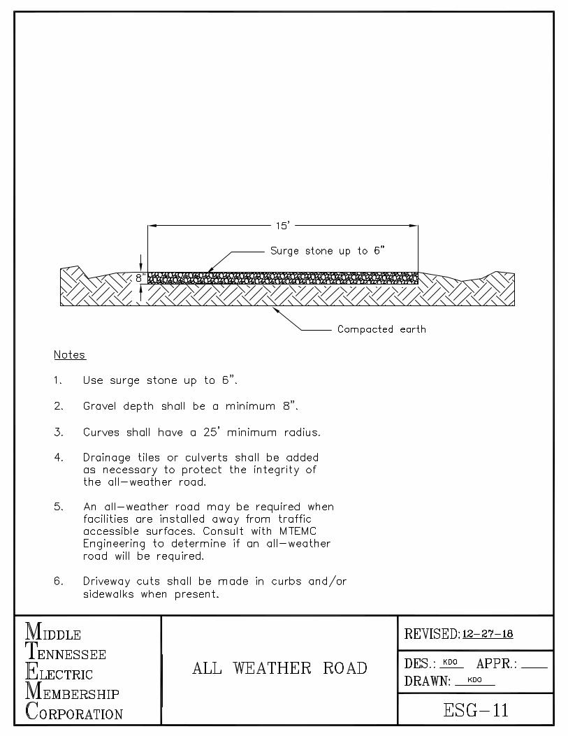
---------- 15' --------
--- Surge stone up to 6"
Notes
1. Use surge stone up to 6".
2. Gravel depth shall be a minimum 8 11•
3. Curves shall have a 25' minimum radius.
4. Drainage tiles or culverts shall be added as necessary to protect the integrity of the all-weather road.
5. An all-weather road may be required when facilities are installed away from traffic accessible surfaces. Consult with MTEMC Engineering to determine if an all-weather road will be required.
6. Driveway cuts shall be made in curbs and/or sidewalks when present.
MIDDLE
TENNESSEE
ELECTRIC
MEMBERSHIP
CoRPORATION
ALL WEATHER ROAD
REVISED: 12-27-18
DES.:~ APPR.: __ DRAWN: KDO
ESG-11

MTEMC Office Locations
FRANKLIN 2156 Curd Lane Franklin, Tennessee 37067
LEBANON 201 Maddox-Simpson Parkway Lebanon, Tennessee 37087
Mt JULIET 1475 North Mt. Juliet Road Mt. Juliet, Tennessee 37122
WOODBURY 911 West Main Woodbury, Tennessee 37190
SMYRNA 505 Nolan Drive Smyrna, Tennessee 37167
MURFREESBORO 326 St. Andrews Drive Murfreesboro, Tennessee 37128
CORPORATE 555 New Salem Highway Murfreesboro, Tennessee 37129
Customer Service: 1-877-777-9020
12/31/2018