electrical installation - schneider electric
TRANSCRIPT

ElectricalInstallation
Symmetra® PX-XRBattery Enclosures
50-80 kW200/208/400 V

About This Manual
Audience
This manual is intended for APC-trained or APC-authorized electricians who will be installing the APC Symmetra® PX-XR (50-80 kW) battery enclosures. This manual provides detailed electrical and physical specifications and battery diagrams. It also provides instructions on how to make electrical connections between the batteries, and how to make electrical connections between the battery enclosures and other components in your system.Read all sections of this document before installing or operating any of this equipment, then keep the manual nearby for reference. Proper installation, operation, and maintenance are needed to ensure continued satisfactory performance from your equipment.
For your informationThe battery enclosures included in this manual are referred to by their APC product numbers: SLB80XRL, SLB80XR, and SLB80XR-E. These products were manufactured and tested in accordance with current industry standards. The assemblies meet UL 1778, cUL, and CE requirements, and are UBC Seismic Zone 4 Certified. Compliance with all applicable codes and regulations is the responsibility of installation personnel. Know these codes and follow them!
Symmetra PX-XR 50-80 kW Battery Enclosures i


Contents
Safety ..................................................................... 1
Symbols and Instructions . . . . . . . . . . . . . . . . . . . . . . . . . . . . . . 1Save these instructions . . . . . . . . . . . . . . . . . . . . . . . . . . . . . . . 1
Safety symbols used in this manual . . . . . . . . . . . . . . . . . . . . . . 1
Cross-reference symbols used in this manual . . . . . . . . . . . . . . . 1
Warnings . . . . . . . . . . . . . . . . . . . . . . . . . . . . . . . . . . . . . . . . . 2Safety warnings . . . . . . . . . . . . . . . . . . . . . . . . . . . . . . . . . . . . 2
Safety practices . . . . . . . . . . . . . . . . . . . . . . . . . . . . . . . . . . . . . 3
Battery Enclosures .................................................. 5
Mechanical Specifications . . . . . . . . . . . . . . . . . . . . . . . . . . . . . 5Enclosures . . . . . . . . . . . . . . . . . . . . . . . . . . . . . . . . . . . . . . . . . 5
Cable access . . . . . . . . . . . . . . . . . . . . . . . . . . . . . . . . . . . . . . . 5
SLB80XRL mechanical . . . . . . . . . . . . . . . . . . . . . . . . . . . . . . . . 6
SLB80XR and SLB80XR-E mechanical . . . . . . . . . . . . . . . . . . . . . 6
Shipping Specifications . . . . . . . . . . . . . . . . . . . . . . . . . . . . . . . 7Receiving the enclosure and batteries . . . . . . . . . . . . . . . . . . . . 7
Handling the enclosure and batteries . . . . . . . . . . . . . . . . . . . . 8
Storing the enclosure and batteries . . . . . . . . . . . . . . . . . . . . . . 8
Installation Specifications . . . . . . . . . . . . . . . . . . . . . . . . . . . . . 9Site requirements . . . . . . . . . . . . . . . . . . . . . . . . . . . . . . . . . . . 9
Site restrictions . . . . . . . . . . . . . . . . . . . . . . . . . . . . . . . . . . . . 10
Tools for installation . . . . . . . . . . . . . . . . . . . . . . . . . . . . . . . . 10
Torque values . . . . . . . . . . . . . . . . . . . . . . . . . . . . . . . . . . . . . 10
Placement of Enclosures . . . . . . . . . . . . . . . . . . . . . . . . . . . . . 11Step-by-step instructions . . . . . . . . . . . . . . . . . . . . . . . . . . . . . 11
Optional seismic mounting . . . . . . . . . . . . . . . . . . . . . . . . . . . 12
Symmetra PX-XR 50-80 kW Battery Enclosures iii

Installation ........................................................... 13
Overview . . . . . . . . . . . . . . . . . . . . . . . . . . . . . . . . . . . . . . . . 13Grounding the enclosures . . . . . . . . . . . . . . . . . . . . . . . . . . . . 13
Mechanical Installation . . . . . . . . . . . . . . . . . . . . . . . . . . . . . . 14SLB80XR and SLB80XR-E enclosures . . . . . . . . . . . . . . . . . . . . . 14
Loading Batteries . . . . . . . . . . . . . . . . . . . . . . . . . . . . . . . . . . 15
Wiring Batteries . . . . . . . . . . . . . . . . . . . . . . . . . . . . . . . . . . . 17SLB80XRL enclosures . . . . . . . . . . . . . . . . . . . . . . . . . . . . . . . . 17
SLB80XR and SLB80XR-E enclosures . . . . . . . . . . . . . . . . . . . . . 19
Connecting to the UPS . . . . . . . . . . . . . . . . . . . . . . . . . . . . . . 21Step-by-step procedure . . . . . . . . . . . . . . . . . . . . . . . . . . . . . . 21
Paralleling Battery Enclosures . . . . . . . . . . . . . . . . . . . . . . . . . 23Step-by-step procedure . . . . . . . . . . . . . . . . . . . . . . . . . . . . . . 23
Installing the Battery Charger . . . . . . . . . . . . . . . . . . . . . . . . . 25Mechanical installation of charger in SLB80XRL enclosures . . . 25
Mechanical installation of charger in SLB80XR or SLB80XR-E enclosures . . . . . . . . . . . . . . . . . . . . . . . . . . . . . . . 25
Electrical installation of charger . . . . . . . . . . . . . . . . . . . . . . . . 26
System Startup ..................................................... 29
Start-up Procedure . . . . . . . . . . . . . . . . . . . . . . . . . . . . . . . . . 29
Specifications ....................................................... 31
System Specifications . . . . . . . . . . . . . . . . . . . . . . . . . . . . . . . 31Power specifications . . . . . . . . . . . . . . . . . . . . . . . . . . . . . . . . 31
SLBC1000 charger specifications . . . . . . . . . . . . . . . . . . . . . . . 32
Battery run times . . . . . . . . . . . . . . . . . . . . . . . . . . . . . . . . . . . 33
iv Symmetra PX-XR 50-80 kW Battery Enclosures
Appendix A: SLB80XRL Electrical ...........................35
Wiring Diagram . . . . . . . . . . . . . . . . . . . . . . . . . . . . . . . . . . . 35
Cabling . . . . . . . . . . . . . . . . . . . . . . . . . . . . . . . . . . . . . . . . . 36Battery terminals . . . . . . . . . . . . . . . . . . . . . . . . . . . . . . . . . . . 36
Cable connections . . . . . . . . . . . . . . . . . . . . . . . . . . . . . . . . . . 36
Appendix B: SLB80XR/SLB80XR-E Electrical ............37
Wiring Diagram . . . . . . . . . . . . . . . . . . . . . . . . . . . . . . . . . . . 37
Cabling . . . . . . . . . . . . . . . . . . . . . . . . . . . . . . . . . . . . . . . . . 38Battery Terminals . . . . . . . . . . . . . . . . . . . . . . . . . . . . . . . . . . 38
Cable connections . . . . . . . . . . . . . . . . . . . . . . . . . . . . . . . . . . 38
Symmetra PX-XR 50-80 kW Battery Enclosures v


Safety
Symbols and Instructions
Save these instructions
This manual contains important instructions that must be followed during installation, operation, and maintenance of the Symmetra® PX-XR 50-80 kW battery enclosures and their contained batteries.
Safety symbols used in this manual
Cross-reference symbols used in this manual
ElectricalHazard
Indicates an electrical hazard which, if not avoided, could result in injury or death!
Warning
Indicates a hazard which, if not avoided, could result in severe personal injury or substantial damage to product or other property!
Heavy
Indicates a heavy load that should not be lifted without assistance.
Note
Indicates important information.
Indicates that more information is available on the same subject in a different section of this manual.
See also
Indicates that more information is available on the same subject in a different manual.
Symmetra PX-XR 50-80 kW Battery Enclosures 1

Warnings
Safety warnings
Warning
WARNING!All electrical power must be installed by a qualified electrician and must comply with local and national codes. Never work inside the battery enclosures alone!
Warning
WARNING!All batteries must be installed and connected by APC-trained or APC-authorized personnel. Never work on the batteries alone!
Warning
WARNING!Battery servicing should be performed or supervised by personnel knowledgeable of batteries and battery precautions. Keep unauthorized personnel away from batteries!
Warning
WARNING!Disconnect charging sources before connecting or disconnecting battery terminals! Be aware that lethal voltages may still be present even when the enclosure is non-operational, or when its switches are in the OFF position!
Warning
WARNING!Contact with any part of a grounded battery can result in electrical shock! Such grounds should be removed prior to installation or servicing!
Warning
WARNING!A battery presents the risk of producing high short-circuit current!
Warning
WARNING!Do not lay tools or metal objects on top of batteries!
Warning
WARNING!Batteries should only be replaced with the same number and type as previously used. These are valve-regulated, lead-acid type batteries!
Warning
WARNING!Do not dispose of a battery in a fire. The battery may explode! Do not open or mutilate batteries. Released electrolyte is harmful to the skin and eyes, and may be toxic!
See also
For configurations that include customer-supplied external batteries, refer to the manufacturer’s battery installation and maintenance instructions.
2 Symmetra PX-XR 50-80 kW Battery Enclosures

Warnings
Safety practices
Always wear:
• Goggles or face shields• Acid-resistant, insulated rubber gloves• Protective overshoes or rubber boots• Protective aprons
Always use:
• Double-insulated tools• Rubber mats to cover batteries during servicing• Rubber mats or rubber stands on the floor• Adequate lifting devices
Remove from your body:
• Watches• Rings• Other metal objects
Symmetra PX-XR 50-80 kW Battery Enclosures 3


Battery Enclosures
Mechanical Specifications
Enclosures
The SLB80XRL, SLB80XR, and SLB80XR-E battery enclosures were designed for installation with the Symmetra PX 80 kW UPS. These enclosures offer long run-time capability, front and rear removable panels, 10-year design life VRLA batteries, and an optional battery charger.
The SLB80XRL fits into the standard NetShelter dimensions and uses front-access batteries, while the SLB80XR and SLB80XR-E use top-terminal batteries. Each of these enclosures houses one full string of 32 batteries. The enclosures have the following physical specifications:
Cable access
The enclosures were designed for hard-wiring a.) from the utility supply (if the charger is used); b.) to the Symmetra PX 80 kW UPS; and c.) between parallel battery enclosures.
There are two conduit landing areas on both sides of the SLB80XRL enclosure (refer to the step 2 graphic on page 15). Conduit fittings are supplied in these areas. The XRL also has a removable plate at the bottom-rear section of the unit. This opening can be used to run cables under a raised floor. The SLB80XR and SLB80XR-E are equipped with several knockouts on all sides.
SKU
Dimensions WeightsWidth Depth Height Unloaded Loaded
mm in mm in mm in kg lb kg lb
SLB80XRL 584 23 897 35.5” 2070 81.5” 372 820 1488 3280
SLB80XR 864 34 897 35.5” 2070 81.5” 315 695 1404 3095
SLB80XR-E 864 34 897 35.5” 2070 81.5” 315 695 1404 3095
Symmetra PX-XR 50-80 kW Battery Enclosures 5

Mechanical Specifications
SLB80XRL mechanical
SLB80XR and SLB80XR-E mechanical
Charger Indicator Lamp
DC Circuit Breaker
2070 [81.5]
2146 [84.5]
Output Terminal Block
Input Terminal Block
REARFRONT
TOP
Removable Lifting Hook (optional)
584 [23]
897 [35.5]
MEASUREMENTS IN MM [IN]
DC Circuit Breaker
Output Terminal Block
FRONT REAR
2070 [82.5]
897 [35.5]
864 [34]
TOP
MEASUREMENTS IN MM [IN]
Input Terminal Block
6 Symmetra PX-XR 50-80 kW Battery Enclosures

Shipping Specifications
The enclosure is wrapped in packaging material and bolted to its pallet for shipment. The pallet is slotted at both ends to allow pallet-jack access. The enclosure can also be moved with a pallet-jack.
Batteries are shipped on a separate pallet and must be installed on-site. The optional battery charger is also shipped separately and must be installed on-site.
Receiving the enclosure and batteries
1. Upon receipt, examine the packaging for signs of rough handling or external damage.– DO NOT remove the enclosure’s protective packaging until the unit is off its pallet and ready
for installation.– DO NOT remove the enclosure from its shipping pallet until all transporting is completed.– A thorough internal inspection should only be made after the enclosure has been positioned
for installation, and before making electrical connections.– DO NOT unpack the batteries until the enclosure has been set in place for installation.– Batteries must be inspected individually for damage (cracks, etc.). DO NOT install damaged
batteries!
2. Record any external or internal damage observed and call the carrier immediately to allow their personnel to conduct an equipment inspection.– DO NOT contact APC first—notify the carrier instead. Otherwise, APC may be unable to
assist in recovering the amount of the claim.– All damage claims should be as specific as possible. Information about the shipment should
appear on the shipping label and related paperwork.– BE SURE to request a copy of the carrier’s inspection report.
3. Make certain the entire shipment has arrived. Compare information from the shipping label against what has been received. If anything is missing, contact APC immediately
Refer to the contact list on the back cover of this manual.
Symmetra PX-XR 50-80 kW Battery Enclosures 7

Shipping Specifications
Handling the enclosure and batteries
Storing the enclosure and batteries
The enclosure and batteries should never be stored outdoors. If they do require storage:• They should be stored indoors, on pallets and still wrapped in their packaging material.• Their pallets should be set on a firm and level surface.• They should be kept in a climate-controlled environment with a temperature range of 17° to
27°C (62° to 80°F) to maximize the life and performance of the batteries.• They must be protected at all times from conductive contaminants, moisture, flammable liquids,
gasses, or corrosive substances.• Be aware that prolonged storage of batteries without recharge could affect battery operation.
The manufacturer recommends recharging batteries every 180 days, at a minimum.
Heavy
Use a properly rated forklift or pallet-jack to transport the enclosure and batteries (still on pallets) to the installation site or to a storage location. The enclosures can weigh up to 364 kg (800 lbs) and the batteries up to 1116 kg (2460 lbs).
Note
Consider the weight restrictions of any floors or elevators that might be used during transportation of these components. Be aware of low doorways and ceilings that might hinder movement of the enclosure. The enclosure is 2070 mm (81.5 in) high.
8 Symmetra PX-XR 50-80 kW Battery Enclosures
Installation Specifications
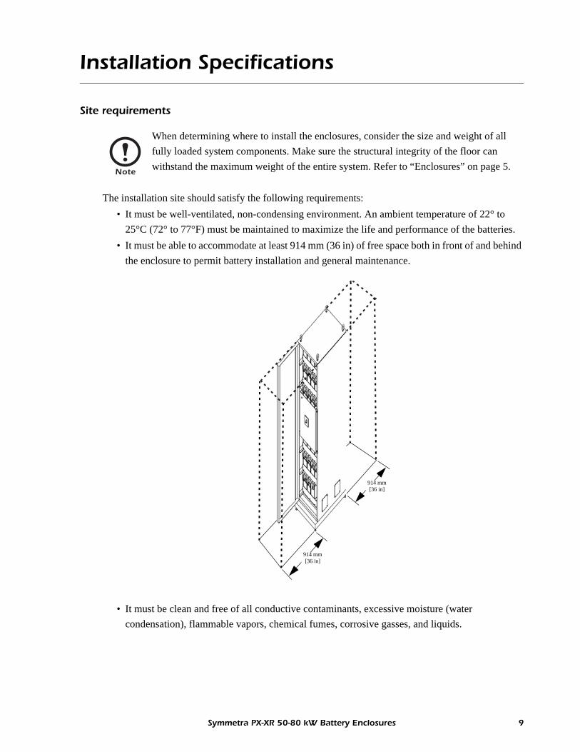
Site requirements
The installation site should satisfy the following requirements:• It must be well-ventilated, non-condensing environment. An ambient temperature of 22° to
25°C (72° to 77°F) must be maintained to maximize the life and performance of the batteries.• It must be able to accommodate at least 914 mm (36 in) of free space both in front of and behind
the enclosure to permit battery installation and general maintenance.
• It must be clean and free of all conductive contaminants, excessive moisture (water condensation), flammable vapors, chemical fumes, corrosive gasses, and liquids.
Note
When determining where to install the enclosures, consider the size and weight of all fully loaded system components. Make sure the structural integrity of the floor can withstand the maximum weight of the entire system. Refer to “Enclosures” on page 5.
914 mm [36 in]
914 mm [36 in]
Symmetra PX-XR 50-80 kW Battery Enclosures 9

Installation Specifications
Site restrictions
The installation site should have the following restrictions:• Prohibit smoking and open flame, and avoid arcing in the immediate vicinity of the batteries.• Ensure there is plenty of light for servicing the batteries and other internal components.• Keep all vents free of dust accumulation that could restrict airflow.• Never block or insert any object into ventilation holes or other openings.• Make sure there is always an unobstructed path from the battery area to an exit.
Tools for installation
The following tools are needed to properly install the SLB80XRL, SLB80XR, and SLB80XR-E battery enclosures:
• Pallet-jack• Torque wrench• Sockets (various sizes) with ratchet or wrench• Voltmeter• Rated lifting devices for installing batteries and enclosures• Strapping kit for the SLB80XR and SLB80XR-E
Torque values
Connection Torque
Grounding: 7.9 Nm (70 lb-in)
Battery terminal: 13.5 Nm (120 lb-in)
DC circuit breaker: 8.1 Nm (72 lb-in)
DC terminal block: 25.7 Nm (228 lb-in)
Charger terminal block: 0.8 Nm (7.1 lb-in)
10 Symmetra PX-XR 50-80 kW Battery Enclosures

Placement of Enclosures
Step-by-step instructions
1. Remove the protective packaging material from the enclosure.
2. Using a 14 mm (9/16 in) socket with ratchet or wrench, remove the four lag screws securing the enclosure to the pallet.
3. These pallets and battery enclosures were designed to use the same ramp that comes with the Symmetra PX80 UPS. Set the ramp into position against the pallet, and then carefully roll the enclosure down the ramp.
4. Roll the enclosure to its final installation position, then adjust (lower) all four stabilizing feet until the pads make solid contact with the floor. Tighten the lock nuts located above the pads at the bottom of the stabilizing feet.
Note
Battery enclosures should be unloaded from their pallets at the installation site.
Heavy
At least two people should be present when unloading an enclosure.
Caution
The enclosure is on casters and may begin to roll once the lag screws have been removed. Take steps to prevent the enclosure from rolling off the edge of the pallet.
Symmetra PX-XR 50-80 kW Battery Enclosures 11

Placement of Enclosures
Optional seismic mounting
Any or all of the battery enclosures can optionally be bolted to a concrete floor to satisfy the requirements of a certified seismic installation, or just to gain additional stability. Refer to the system drawing provided with your enclosure(s).
The following table shows the minimum anchoring and torque requirements for each seismic zone.
Note
Seismic mounting requires removal of the casters from the enclosure.
Seismic Zones Anchor Torque
I, IIA, IIB, III 3/8 in Redhead Wedge anchor x 3 3/4 in 30.4 Nm (300 lb-in)
IV 1/2 in Redhead Wedge anchor x 4 1/4 in 74.5 Nm (600 lb-in)
12 Symmetra PX-XR 50-80 kW Battery Enclosures

Installation
Overview
The system’s main mechanical and electrical drawings and wiring diagrams are shipped with the battery enclosure. Wiring information for the SLB80XRL is also provided in “Appendix A: SLB80XRL Electrical” on page 35. Wiring information for the SLB80XR and SLB80XR-E is provided in “Appendix B: SLB80XR/SLB80XR-E Electrical” on page 37.
All of this information has been made available as reference material. During installation, use the system drawings and wiring diagrams as your primary guides.
Grounding the enclosures
Each enclosure contains one or more 6.5 mm (1/4 in)-20 ground studs and connecting hardware. To properly ground the battery enclosure, connect the supplied (green and yellow) grounding cables to the appropriate stud(s) as specified in Appendices A or B. Secure ground cables with 7.9 Nm (70 lb-in) of torque. See the below graphic for ground connection options to the Symmetra PX80 UPS. Secure this connection with 7.9 Nm (70 lb-in) of torque.
Symmetra PX80 UPS
GroundGround
Symmetra PX-XR 50-80 kW Battery Enclosures 13
Mechanical Installation
SLB80XR and SLB80XR-E enclosures
Two or more SLB80XR or SLB80XR-E battery enclosures can optionally be bolted together in a side-by-side configuration at the final installation location. It is recommended that mechanical connection takes place before making any electrical connections inside or to the enclosure.
1. Open each enclosure’s front door and remove its back panel to gain full internal access to both enclosures. The front door has a keyed lock identical to the lock on the UPS.
2. Remove the “facing” side panels on each of the enclosures being joined. This will expose the four matching holes needed for mechanical connection.
3. Use a rated lifting device to position the enclosures adjacent to one another with the four matching holes aligned. Adjust the height of either or both enclosures by raising or lowering their leveling feet to achieve alignment.
4. Use 13 mm (1/2 in) hardware (bolt head/washer on one side, washer/lockwasher/nut on the other side) to join the enclosures. Hardware is not supplied. Bind enclosures until rigid.
Note
SLB80XRL enclosures DO NOT have provisions for mechanical installation. Its side panels are part of the enclosure structure and cannot be removed.
14 Symmetra PX-XR 50-80 kW Battery Enclosures
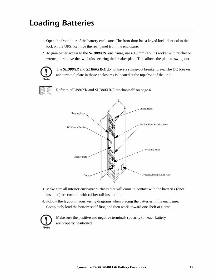
Loading Batteries
1. Open the front door of the battery enclosure. The front door has a keyed lock identical to the lock on the UPS. Remove the rear panel from the enclosure.
2. To gain better access to the SLB80XRL enclosure, use a 13 mm (1/2 in) socket with ratchet or wrench to remove the two bolts securing the breaker plate. This allows the plate to swing out.
3. Make sure all interior enclosure surfaces that will come in contact with the batteries (once installed) are covered with rubber rail insulation.
4. Follow the layout in your wiring diagrams when placing the batteries in the enclosure. Completely load the bottom shelf first, and then work upward one shelf at a time.
Note
The SLB80XR and SLB80XR-E do not have a swing-out breaker plate. The DC breaker and terminal plate in those enclosures is located at the top-front of the unit.
Refer to “SLB80XR and SLB80XR-E mechanical” on page 6.
Note
Make sure the positive and negative terminals (polarity) on each battery are properly positioned.
Breaker Plate Securing Bolts
Retaining Plate
Conduit Landing Cover PlateBattery
DC Circuit Breaker
Charging Light
Breaker Plate
Lifting Hook
Symmetra PX-XR 50-80 kW Battery Enclosures 15

Loading Batteries
5. Using a voltmeter, measure the voltage of all batteries to ensure they contain an acceptable charge. Each 12 V battery should measure 12.6 V or greater.
6. After all of the batteries have been loaded into the enclosure, secure them in place:
Note
DO NOT install any batteries that fail to contain an acceptable charge!
Note
For the SLB80XRL, use additional adhesive-backed rubber rail insulation on the inside of the front retaining plates. Install these plates using the supplied attachment bolts. If installed correctly, the batteries should not move at all.
Note
For the SLB80XR and SLB80XR-E, use a strapping kit to secure each row of batteries to its assigned shelf.
16 Symmetra PX-XR 50-80 kW Battery Enclosures

Wiring Batteries
SLB80XRL enclosures“Appendix A: SLB80XRL Electrical” on page 35Complete the inter-battery connections:
1. Complete the inter-battery connections:– Make the 25 battery-to-battery connections. Start with the batteries at the top of the enclosure
and work down.– Make the six shelf-to-shelf connections. Start with the top shelf and work down.
2. After all of the inter-battery connections have been made, use a voltmeter to measure the voltage of the entire string.
Note
The following instructions apply only to the SLB80XRL battery enclosures.
ElectricalHazard
Refer to “Safety” on page 1, and pay strict attention to all safety warnings and other relevant safety instructions before making connections. Failure to follow the recommended safety measures could result in serious injury or death!
Refer to “Appendix A: SLB80XRL Electrical” on page 35 and your wiring diagrams before making connections.
Note
• Pay special attention to battery polarities before making contact with cable lugs.• Apply No-Ox grease (supplied) to each battery terminal before and after connection.• Torque connections to the first setting displayed on the battery (13.5 Nm/120 lb-in).
Note
BEFORE making the final shelf-to-shelf connection, use a voltmeter to measure the voltage between the battery terminals that will be interconnected. If there is more than a one- to two-volt difference, recheck the battery connection sequence to ensure correct polarities. DO NOT MAKE THE FINAL SHELF-TO-SHELF CONNECTION UNTIL CORRECT POLARITES FOR ALL INTERCONNECTS ARE VERIFIED.
Note
This reading should be +/- 216 to +/- 220.8 VDC (432 to 441.6 V). If your reading is not within this range, check the connections and take another reading. If the reading is still outside this range, recheck the individual battery voltages.
Symmetra PX-XR 50-80 kW Battery Enclosures 17

Wiring Batteries
3. Complete the connections between the batteries and the DC circuit breaker:– Make the negative connection between the last battery (- terminal) in the bottom row of the
enclosure and the negative (-) terminal at the top of the circuit breaker.– Make the midpoint connection between the fourth battery (c/t terminal) in the fourth row of
the enclosure and the midpoint (C/T) terminal at the top of the circuit breaker.– Make the positive connection between the first battery (+ terminal) in the top row of the
enclosure and the positive (+) terminal at the top of the circuit breaker.
4. To ensure there are no inadvertent grounds, use a voltmeter to measure voltage between the positive (+) terminal on the breaker and the enclosure ground. Do the same between the negative (-) terminal on the breaker and the enclosure ground.
5. The DC circuit breaker has been prewired to the output terminal block per the above graphic.
Note
• Apply No-Ox grease (supplied) to each battery terminal before and after connection.• Torque the battery terminal connections and the DC circuit breaker connections to
13.5 Nm (120 lb-in).
Note
Each of these readings should be less than 0.5 V.
+- C/TFrom last battery in bottom row
From first battery in top row
From fourth battery in fourth row
Preconnected cables to output terminal block
DC Circuit Breaker
18 Symmetra PX-XR 50-80 kW Battery Enclosures

Wiring Batteries
SLB80XR and SLB80XR-E enclosures
1. Complete the inter-battery connections:– Make the 24 battery-to-battery connections. Start with the batteries at the top of the enclosure
and work down.– Make the four row-to-row connections. Start with the top shelf and work down.– Make the three shelf-to-shelf connections. Start with the top shelf and work down.
2. After all of the inter-battery connections have been made, use a voltmeter to measure the voltage of the entire string.
Note
The following instructions apply only to SLB80XR and SLB80XR-E battery enclosures.
ElectricalHazard
Refer to “Safety” on page 1, and pay strict attention to all safety warnings and relevant safety instructions before making connections. Failure to follow the recommended safety measures could result in serious injury or death!
Refer to “Appendix B: SLB80XR/SLB80XR-E Electrical” on page 37 and your wiring diagrams before making connections.
Note
• Pay special attention to battery polarities before making contact with cable lugs.• Apply No-Ox grease (supplied) to each battery terminal before and after connection.• Torque connections to the first setting displayed on the battery (13.5 Nm/120 lb-in).
Note
BEFORE making the final shelf-to-shelf connection, use a voltmeter to measure the voltage between the battery terminals that will be interconnected. If there is more than a one- to two-volt difference, recheck the battery connection sequence to ensure correct polarities. DO NOT MAKE THE FINAL SHELF-TO-SHELF CONNECTION UNTIL CORRECT POLARITES FOR ALL INTERCONNECTS ARE VERIFIED.
Note
This reading should be +/- 216 to +/- 220.8 VDC (432 to 441.6 V). If your reading is not within this range, check the connections and take another reading. If the reading is still outside this range, recheck the individual battery voltages.
Symmetra PX-XR 50-80 kW Battery Enclosures 19

Wiring Batteries
3. Complete the connections between the batteries and the DC circuit breaker:– Make the negative connection between the last battery (- terminal) in the bottom row of the
enclosure and the negative (-) terminal on the right side of the circuit breaker.– Make the midpoint connection between the first battery (+ terminal) in the third row of the
enclosure and the midpoint (C/T) terminal on the right side of the circuit breaker.– Make the positive connection between the first battery (+ terminal) in the top row of the
enclosure and the positive (+) terminal on the right side of the circuit breaker.
4. To ensure there are no inadvertent grounds, use a voltmeter to measure voltage between the positive (+) terminal on the breaker and the enclosure ground. Do the same between the negative (-) terminal on the breaker and the enclosure ground.
5. The DC circuit breaker has been prewired to the output terminal block per the above graphic.
Note
The DC circuit breaker in the SLB80XR has been rotated 90 degrees clockwise. The inputs are on the right and the outputs are on the left.
Note
• Apply No-Ox grease (supplied) to each battery terminal before and after connection.• Torque the battery terminal connections and the DC circuit breaker connections to
13.5 Nm (120 lb-in).
Note
Each of these readings should be less than 0.5 V.
+
-
C/T
From last battery in bottom row
From first battery in top row
From first battery in third row
DC Circuit Breaker
Pre-
conn
ecte
d ca
bles
to
outp
ut te
rmin
al b
lock
20 Symmetra PX-XR 50-80 kW Battery Enclosures

Connecting to the UPS
Step-by-step procedure
70mm2 (2/0) cables are supplied for connection between the output terminal block and the UPS. If the cable length is not sufficient, use alternative cables with equivalent ratings that meet all applicable codes. Consider also any special compensation needed for long cable runs.
1. Switch the DC circuit breaker ON (closed).
2. Use a voltmeter to measure the voltage between the outer terminals on the terminal block.
ElectricalHazard
Refer to “Safety” on page 1, and pay strict attention to all safety warnings and relevant safety instructions before making connections. Failure to follow the recommended safety measures could result in serious injury or death!
ElectricalHazard
Refer to the documentation provided with your UPS for recommended UPS safety instructions before making these connections. Failure to follow these safety measures could result in serious injury or death!
ElectricalHazard
Pay particular attention to the polarity of the terminals used during measurement. Damage or explosion could occur if incorrect polarities are connected.
Note
This reading should be +/- 198.4 to +/- 206.4 VDC (396.8 to 412.8 V). If your reading is not within this range, check the battery connections and take another reading. If the reading is still outside this range, recheck the individual battery voltages.
SLB80XRL (REAR) SLB80XR/XR-E (FRONT)
Output Terminal Block
Output Terminal Block
Symmetra PX-XR 50-80 kW Battery Enclosures 21

Connecting to the UPS
3. Use a voltmeter to measure the voltage between the outer terminals and the center terminal.
7. Re-attach the protective cover to the output terminal block.
ElectricalHazard
Pay particular attention to the polarity of the terminals used during measurement. Damage or explosion could occur if incorrect polarities are connected.
Note
These readings should be about half the total system voltage, and nearly equal to one another. If more than a two-volt difference, check the battery connections and take additional readings. If readings are still bad, recheck the individual battery voltages.
4. Switch the circuit breaker OFF (open).
5. Remove the protective cover from the output terminal block.
6. Connect six 70 mm2 (2/0) cables from the output terminal block to the UPS (below graphic). Two 2/0 cables are required at each connection point (right graphic shows proper positioning of cable lugs).
Note
Make certain each cable from the output terminal block connects to the proper polarity on the UPS. Torque to 31.0 Nm (275 lb-in).
Two cables perconnection
Battery Enclosure’s Output Terminal Block Symmetra
PX80 UPS
22 Symmetra PX-XR 50-80 kW Battery Enclosures
Paralleling Battery Enclosures
Step-by-step procedure
Up to six battery enclosures can be paralleled to the UPS. If your installation involves multiple battery enclosures, start the process by installing and wiring all batteries in each enclosure.
1. Before paralleling battery enclosures, switch their DC circuit breakers ON (closed) and use a voltmeter to measure the voltage at each terminal block involved in the connection:
– Measure the voltage between the outer terminals on each terminal block.
– Measure the voltage between the outer terminals and the center terminal.
ElectricalHazard
Refer to “Safety” on page 1, and pay strict attention to all safety warnings and relevant safety instructions before making connections. Failure to follow the recommended safety measures could result in serious injury or death!
Refer to “Mechanical Installation” on page 14 through “Wiring Batteries” on page 17.
Note
When making connections between battery enclosures, use the same cable type (70 mm2 or 2/0) that was used to connect the first enclosure to the UPS.
ElectricalHazard
Pay particular attention to the polarity of the terminals during measurement. Damage or explosion could occur if incorrect polarities are connected.
Note
This reading should be +/- 198.4 to +/- 206.4 VDC (396.8 to 412.8 V). If your reading is not within this range, check the battery connections and take another reading. If the reading is still outside this range, recheck the individual battery voltages.
Note
These readings should be about half the total system voltage, and nearly equal to one another. If more than a two-volt difference, check the battery connections and take additional readings. If readings are still bad, recheck the individual battery voltages.
Symmetra PX-XR 50-80 kW Battery Enclosures 23

Paralleling Battery Enclosures
2. Once the voltage readings are satisfactory, switch OFF (open) ALL DC circuit breakers.
3. Remove the protective covers from both terminal blocks, and proceed as follows:– Connect two cables to each terminal (-, C/T and +) in the output terminal block of the second
battery enclosure and torque to 31.0 Nm (275 lb-in). Re-attach the protective cover.– Connect these same cables to identical terminals (-, C/T and +) in the input terminal block of
the first battery enclosure and torque to 31.0 Nm (275 lb-in). Re-attach the protective cover.
4. If more than two battery enclosures are being paralleled, follow the same test procedures outlined in step 1 on page 23. Once the voltage readings are satisfactory, switch OFF (open) ALL DC circuit breakers.
5. Remove the protective covers from both terminal blocks, and proceed: – Connect two cables to each terminal (-, C/T and +) in the output terminal block of the third
battery enclosure and torque to 31.0 Nm (275 lb-in). Re-attach the protective cover.– Connect the same cables to identical terminals (-, C/T and +) in the input terminal block of the
second battery enclosure and torque to 31.0 Nm (275 lb-in). Re-attach the protective cover.– Repeat this process when paralleling additional battery enclosures (maximum of six).
Refer to the appropriate drawing on page 35 or page 37.
Refer to the appropriate drawing on page 35 or page 37.
Second Battery Enclosure First Battery Enclosure
Input Output Input Output
To UPS
Third Battery Enclosure Second Battery Enclosure
Input Output Input Output
To FirstBatteryEnclosure
24 Symmetra PX-XR 50-80 kW Battery Enclosures

Installing the Battery Charger
The battery enclosures are designed to include the optional SLBC1000 (384 VDC, 5 Amp) charger. This charger is used to reduce the recharge time when employing multiple (3+) enclosures.
Mechanical installation of charger in SLB80XRL enclosures
The SLBC1000 is mechanically connected at the rear of the SLB80XRL battery enclosure, where six holes have been provided above the power distribution block.
1. Insert two supplied 8 mm (5/16 in)-18 thread-forming screws into the uppermost holes at the rear of the enclosure. DO NOT tighten the screws at this time.
2. With two people lifting, hang the charger from these screws using the keyholes at the top of the charger plate.
3. Insert the other four supplied 8 mm (5/16 in)-18 thread-forming screws through the plate and into the remaining holes provided for attachment of this assembly.
4. Tighten all six screws.
Mechanical installation of charger in SLB80XR or SLB80XR-E enclosures
The SLBC1000 is mechanically connected at the top of both the SLB80XR and SLB80XR-E battery enclosures, where two mounting rails are provided behind the circuit breaker plate. The SLBC1000 must be installed from the rear of these enclosures.
1. Open the circuit breaker plate at the top of the enclosure to gain access to the mounting rails.
2. With two people lifting, lay the charger flat onto the rails in such a way that its transformer is facing up.
3. Slide the charger along the rails until the four holes in its plate line up with the four holes on the mounting rails.
4. Insert the four supplied 8 mm (5/16 in)-18 thread-forming screws through the matching holes and tighten.
ElectricalHazard
Refer to “Safety” on page 1, and pay strict attention to all safety warnings and relevant safety instructions before installing the charger. Failure to follow the recommended safety measures could result in serious injury or death!
Refer to “SLBC1000 charger specifications” on page 32.
Note
The charger DOES NOT support 200 V installations.
Symmetra PX-XR 50-80 kW Battery Enclosures 25

Installing the Battery Charger
Electrical installation of charger
The SLBC1000 charger is electrically connected in exactly the same way in all of these battery enclosure models. After the batteries have been installed and wired inside the enclosure, the charger must be electrically connected to the utility supply and the battery string.
1. Ensure the AC input voltage is properly configured.
The SLBC1000 can be powered by 208, 220, 230, or 240 VAC (50 or 60 Hz). Jumper settings for each of these four voltages are provided. Check the charger terminal block to make sure the jumper is configured for the proper voltage. If not, connect the jumper to its proper voltage setting and torque to 0.8 Nm (7.1 lb-in).
2. Switch the battery breaker OFF.
If the battery enclosure was already connected to the UPS, switch OFF (open) the circuit breaker in the enclosure.
Note
The charger DOES NOT support 200 V installations.
Note
Plan for the fact that the UPS will no longer have the same run-time capability due to its broken connection with the battery enclosure.
GR
OU
ND
FUSE
GR
OU
ND
AC
INPU
T
AC
INPU
T
INTE
RN
AL
USE
INTE
RN
AL
USE
SELE
CT
INPU
T 24
0V
SELE
CT
INPU
T 23
0V
SELE
CT
INPU
T 22
0V
SELE
CT
INPU
T 20
8V
OU
TPU
T -
OU
TPU
T +
STO
PPER
Voltage Selection Jumper
26 Symmetra PX-XR 50-80 kW Battery Enclosures

Installing the Battery Charger
3. Connect the “50 A connectors with cables” to the batteries.
The charger is supplied with two grey-colored “50 A connectors with cables” for connecting the battery string to the charger. Connect the positive cable to the “+” terminal on battery #1, and then connect the negative cable to the “-” terminal on battery #32.
4. Measure the voltage on the 50 A connectors.
Use a voltmeter to measure the voltage on the cables that were just connected to the battery terminals. Pay particular attention to the polarity of the reading.
5. Connect the 50 A connectors to the charger.
Connect the 50 A “female” connectors to their matching “male” connectors on the charger.
6. Install the indicator lamp on the enclosure.
The indicator lamp can be found at the end of two long cables extending from the charger circuit board. The cables are attached to the lamp with fast-on tab connectors. – Pull the tab connectors off the lamp to free it from the cable ends.– Insert the lamp through the 13 mm (1/2 in) diameter hole on the breaker plate, with its lens
facing toward the front of the cabinet. Snap into position.– Route the previously disconnected cables back to the lamp and reconnect.
Note
When connecting the cables to the battery terminals, make sure you also re-attach the cables that were previously connected to these terminals. Torque the battery terminal connections to 13.5 Nm (120 lb-in).
Note
This reading should be +/- 198.4 to +/- 206.4 VDC (396.8 to 412.8 V), provided the string is off-line and the voltages have stabilized. The voltage may be slightly higher if the batteries were only recently taken off-line from the UPS.
If your reading is not within this range, check the battery connections and take another reading. If the reading is still outside this range, check the individual voltages.
Symmetra PX-XR 50-80 kW Battery Enclosures 27

Installing the Battery Charger
7. Connect AC power cables to the charger.
Check to make sure the AC input circuit uses the same voltage as selected in step 1 on page 26. Also make sure the circuit is able to meet the necessary current rating.
– Run the input cables into the battery enclosure using the most convenient access points. Refer to “Cable access” on page 5.
– Connect these cables to the two terminals marked “AC INPUT” on the charger terminal block. Refer to the step 1 graphic on page 26 for proper termination points. Torque both connections to 0.8 Nm (7.1 lb-in).
8. Verify the electrical connections.
Once all connections have been made, re-energize the AC input circuit to the charger. – The indicator lamp should light within a few seconds after power up.– Use a voltmeter to measure battery voltage. The reading should be higher than the open
circuit value measured in Step 4 on page 27, and should continue to rise. It will stop rising when it reaches the float voltage setting provided on page 32.
9. Switch the battery breaker ON.
To place the battery enclosure in service, switch ON (close) the DC circuit breaker.
See also
Refer to the specifications provided with the charger.
ElectricalHazard
De-energize the AC circuit before making any power connections to the charger.
Note
The actual value may vary slightly due to the temperature compensation of the charger. If the voltage varies greatly from the setting provided in the charger specifications, contact APC for assistance.
Refer to the contact list on the back cover of this manual.
28 Symmetra PX-XR 50-80 kW Battery Enclosures

System Startup
Start-up Procedure
1. Make certain the DC circuit breaker in all battery enclosures is OFF (open).
2. Using a voltmeter, measure the voltage at the terminal blocks of each battery enclosure in accordance with steps 2 and 3 starting on page 21.
3. Once the voltages are satisfactory, switch the DC circuit breaker(s) ON (closed).
4. If the optional SLBC1000 charger is used in one or more battery enclosures, follow all start-up procedures relating to the charger. If not, proceed to step 5.
5. Start the UPS.
6. After completing startup, close all the battery enclosures:– Re-attach the rear panel and secure it with previously removed bolts. – Close and bolt in place the breaker plate on the XRL enclosure(s).– Close and lock the front door.
Note
If using multiple battery enclosures with optional SLBC1000 chargers, the “charging” light on one or more of these enclosures may go out when the batteries are fully charged. This should NOT be considered a problem, unless all charging lights go out or a light fails to turn on after the batteries have been discharged.
See also
Refer to the instructions provided with the charger.
Note
Startup of the charger(s) must take place before start-up of the Symmetra PX80 UPS.
See also
Refer to the start-up instructions provided with the UPS. Refer specifically to start-up instructions in instances when the UPS is using external batteries.
Symmetra PX-XR 50-80 kW Battery Enclosures 29

Specifications
System Specifications
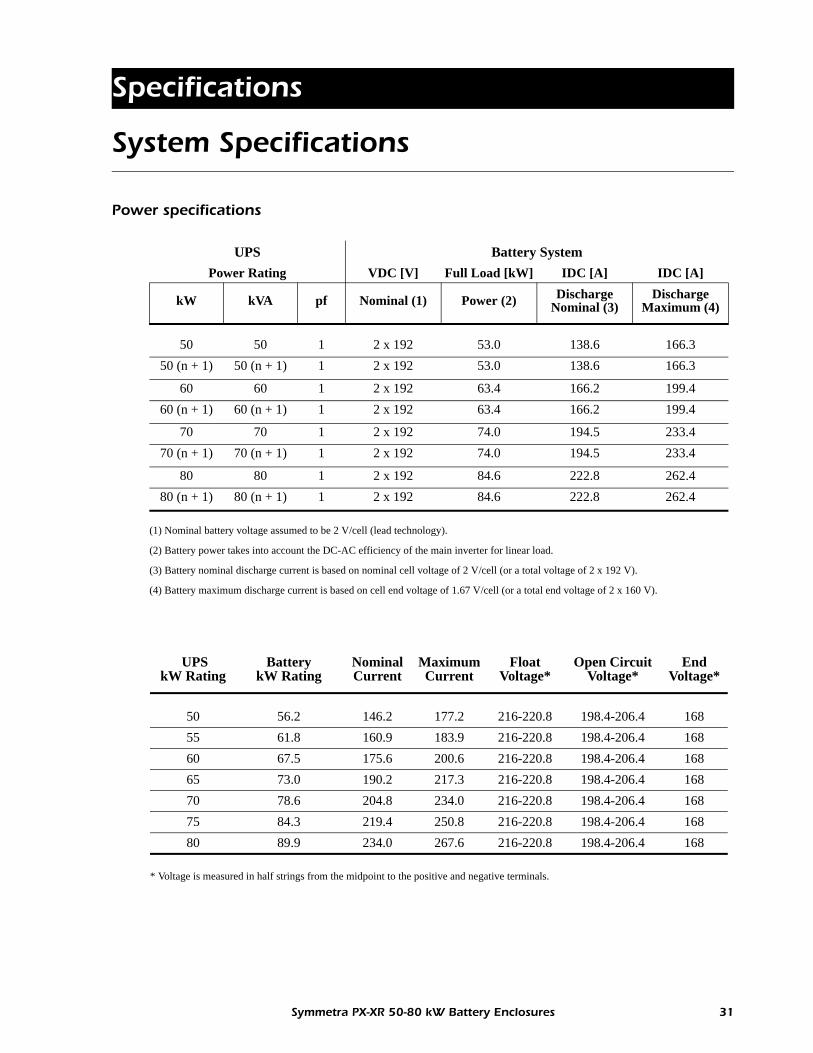
Power specifications
UPS Battery SystemPower Rating VDC [V] Full Load [kW] IDC [A] IDC [A]
kW kVA pf Nominal (1) Power (2) Discharge Nominal (3)
Discharge Maximum (4)
50 50 1 2 x 192 53.0 138.6 166.350 (n + 1) 50 (n + 1) 1 2 x 192 53.0 138.6 166.3
60 60 1 2 x 192 63.4 166.2 199.460 (n + 1) 60 (n + 1) 1 2 x 192 63.4 166.2 199.4
70 70 1 2 x 192 74.0 194.5 233.470 (n + 1) 70 (n + 1) 1 2 x 192 74.0 194.5 233.4
80 80 1 2 x 192 84.6 222.8 262.480 (n + 1) 80 (n + 1) 1 2 x 192 84.6 222.8 262.4
(1) Nominal battery voltage assumed to be 2 V/cell (lead technology).
(2) Battery power takes into account the DC-AC efficiency of the main inverter for linear load.
(3) Battery nominal discharge current is based on nominal cell voltage of 2 V/cell (or a total voltage of 2 x 192 V).
(4) Battery maximum discharge current is based on cell end voltage of 1.67 V/cell (or a total end voltage of 2 x 160 V).
UPS kW Rating
BatterykW Rating
Nominal Current
Maximum Current
Float Voltage*
Open Circuit Voltage*
End Voltage*
50 56.2 146.2 177.2 216-220.8 198.4-206.4 16855 61.8 160.9 183.9 216-220.8 198.4-206.4 16860 67.5 175.6 200.6 216-220.8 198.4-206.4 16865 73.0 190.2 217.3 216-220.8 198.4-206.4 16870 78.6 204.8 234.0 216-220.8 198.4-206.4 16875 84.3 219.4 250.8 216-220.8 198.4-206.4 16880 89.9 234.0 267.6 216-220.8 198.4-206.4 168
* Voltage is measured in half strings from the midpoint to the positive and negative terminals.
Symmetra PX-XR 50-80 kW Battery Enclosures 31

System Specifications
SLBC1000 charger specifications
UPS
Input Voltage: 200 V/208 V/400 V
Battery
Nominal Voltage: +/- 192 VDCFloat Voltage: +/- 219 VDCBoost Charge Voltage: n/aEnd of Discharge Voltage (1): +/- 160 VDCTemperature Compensation: -320 mV per degrees C for T > 25° C
OmV per degrees C for T < 25° C
Battery Charging (2): 8 kWBattery Charging (3): 9 kW
(1) May be higher or less than full load.
(2) N system = 8 power modules. May drop to lower values at low AC Mains.
(3) N + 1 system = 9 power modules. May drop to lower values at low AC Mains.
SLBC1000 Charger
Weight: 68.2 Kg [150 lbs]
Height*: 178 mm [7 in]
Width*: 730 mm [28.75 in]
Depth*: 444 mm [17.5 in]
Float Voltage: 441.6 VDC
Max DC Current: 5 Amps
Max AC Current (208 VAC): 18.7 Amps
Max AC Current (220 VAC): 16.8 Amps
Max AC Current (230 VAC): 16.6 Amps
Max AC Current (240 VAC): 16.3 Amps
Heat Output (at max current): 900 BTU
Heat Output (at float current): 40 BTU
* Dimensions are based on charger laying flat on its back.
32 Symmetra PX-XR 50-80 kW Battery Enclosures

System Specifications
Battery run times
The chart below contains general approximations (in minutes) of battery run times* for the SLB80XRL, SLB80XR, and SLB80XR-E battery enclosures. These approximations are based on using from one to six enclosures containing the specified batteries.
Refer to “Enclosures” on page 5.
Note
Be aware that battery run time can be affected by environmental conditions and the age of the batteries.
Number of XRL, XR, or XR-E Battery Enclosures
UPS kW Rating
BatterykW Rating
1 2 3 4 5 6
50 56.2 15 42 72 107 145 18055 61.8 13 37 64 93 129 16260 67.5 11 33 57 83 114 15065 73.0 10 30 51 74 100 13570 78.6 8 27 46 67 91 12075 84.3 7 24 42 62 83 10580 89.9 6 22 39 57 76 95
* Run times do not include any existing battery modules in the UPS.
Symmetra PX-XR 50-80 kW Battery Enclosures 33


Appendix A: SLB80XRL Electrical
Wiring Diagram
Battery-to-battery (25)
Shelf-to-shelf (6)
Battery midpoint-to-breaker (1)
Battery positive-to-breaker (1)
Battery negative-to-breaker (1)
Inputs from parallel enclosure (6)
Outputs to UPS or parallel enclosure (6)
Ground from parallel enclosure (1)
Ground to UPS or parallel enclosure (1)
TERMINAL BLOCK (see Detail A below)
DC BREAKER
INPUT TERMINAL BLOCK
OUTPUT TERMINAL BLOCK
GROUNDING STUD(see Detail B below)
DETAIL A - TERMINAL BLOCK DETAIL B - GROUNDING HARDWARE
1/4”-20 StudHex Nut
Lockwasher
Stud
Washer
Serrated Washer
Cable Lug
Cable Lug
1 2 3 4 5 6
NC NOCOM
AUXCONTACTS
SHUNTTRIP
C1C2121114
FROM BREAKER
Symmetra PX-XR 50-80 kW Battery Enclosures 35
Cabling
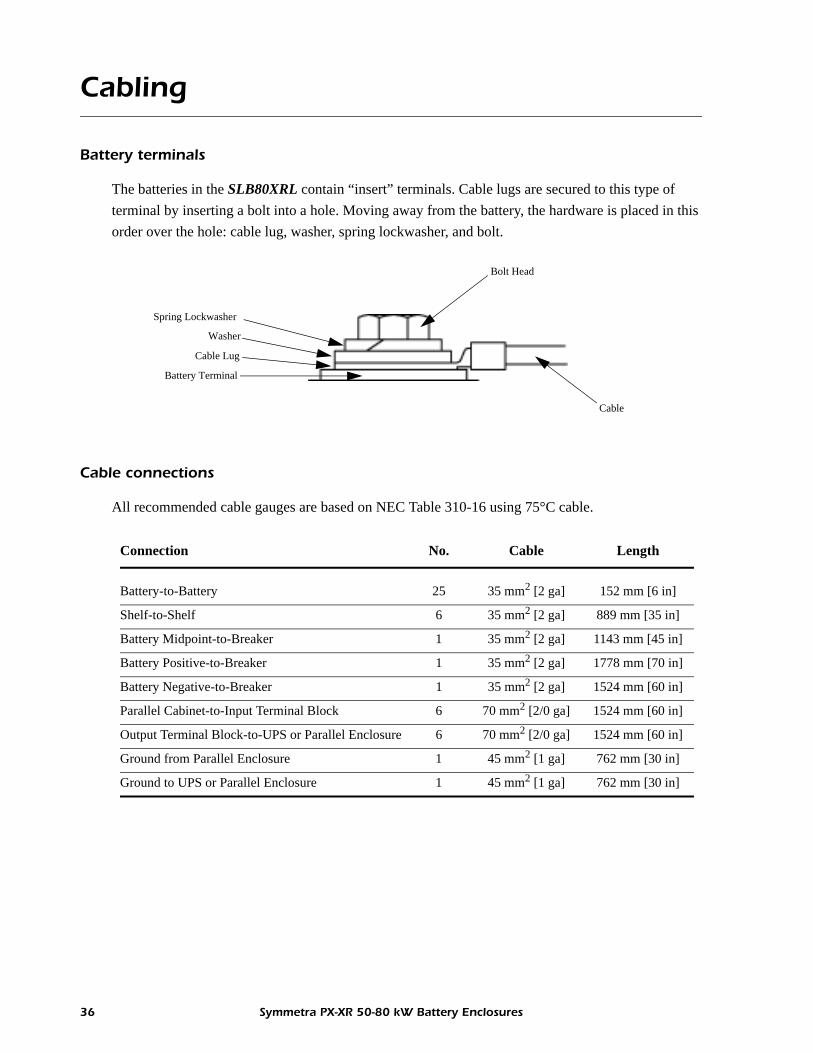
Battery terminals
The batteries in the SLB80XRL contain “insert” terminals. Cable lugs are secured to this type of terminal by inserting a bolt into a hole. Moving away from the battery, the hardware is placed in this order over the hole: cable lug, washer, spring lockwasher, and bolt.
Cable connections
All recommended cable gauges are based on NEC Table 310-16 using 75°C cable.
Battery Terminal
Cable
Cable Lug
Washer
Spring Lockwasher
Bolt Head
Connection No. Cable Length
Battery-to-Battery 25 35 mm2 [2 ga] 152 mm [6 in]
Shelf-to-Shelf 6 35 mm2 [2 ga] 889 mm [35 in]
Battery Midpoint-to-Breaker 1 35 mm2 [2 ga] 1143 mm [45 in]
Battery Positive-to-Breaker 1 35 mm2 [2 ga] 1778 mm [70 in]
Battery Negative-to-Breaker 1 35 mm2 [2 ga] 1524 mm [60 in]
Parallel Cabinet-to-Input Terminal Block 6 70 mm2 [2/0 ga] 1524 mm [60 in]
Output Terminal Block-to-UPS or Parallel Enclosure 6 70 mm2 [2/0 ga] 1524 mm [60 in]
Ground from Parallel Enclosure 1 45 mm2 [1 ga] 762 mm [30 in]
Ground to UPS or Parallel Enclosure 1 45 mm2 [1 ga] 762 mm [30 in]
36 Symmetra PX-XR 50-80 kW Battery Enclosures

Appendix B: SLB80XR/SLB80XR-E Electrical
Wiring Diagram
Battery-to-battery (24)
Row-to-row (4)
Shelf-to-shelf (3)
Battery midpoint-to-breaker (1)
Battery positive-to-breaker (1)
Battery positive-to-breaker (1)
INPUT TERMINAL BLOCK
OUTPUT TERMINAL BLOCK
DC BREAKER
TERMINAL BLOCK (see Detail A below)
(see Detail B below)
Outputs to UPS or parallel enclosure (6)
Inputs from parallel enclosure (6)
GROUND to UPS or parallel enclosure (1)Ground from parallel enclosure (1)
Ground to door (1)
DETAIL A - TERMINAL BLOCK DETAIL B - GROUNDING HARDWARE
1/4”-20 StudHex Nut
LockwasherWasher
Serrated Washer
Cable Lug
Cable Lug
Symmetra PX-XR 50-80 kW Battery Enclosures 37
Cabling
Battery Terminals
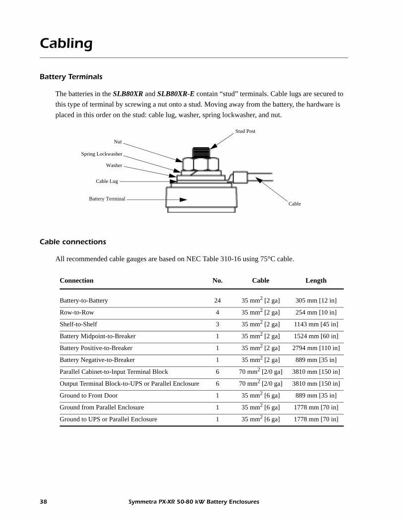
The batteries in the SLB80XR and SLB80XR-E contain “stud” terminals. Cable lugs are secured to this type of terminal by screwing a nut onto a stud. Moving away from the battery, the hardware is placed in this order on the stud: cable lug, washer, spring lockwasher, and nut.
Cable connections
All recommended cable gauges are based on NEC Table 310-16 using 75°C cable.
Battery TerminalCable
Cable Lug
Washer
Spring Lockwasher
Nut
Stud Post
Connection No. Cable Length
Battery-to-Battery 24 35 mm2 [2 ga] 305 mm [12 in]
Row-to-Row 4 35 mm2 [2 ga] 254 mm [10 in]
Shelf-to-Shelf 3 35 mm2 [2 ga] 1143 mm [45 in]
Battery Midpoint-to-Breaker 1 35 mm2 [2 ga] 1524 mm [60 in]
Battery Positive-to-Breaker 1 35 mm2 [2 ga] 2794 mm [110 in]
Battery Negative-to-Breaker 1 35 mm2 [2 ga] 889 mm [35 in]
Parallel Cabinet-to-Input Terminal Block 6 70 mm2 [2/0 ga] 3810 mm [150 in]
Output Terminal Block-to-UPS or Parallel Enclosure 6 70 mm2 [2/0 ga] 3810 mm [150 in]
Ground to Front Door 1 35 mm2 [6 ga] 889 mm [35 in]
Ground from Parallel Enclosure 1 35 mm2 [6 ga] 1778 mm [70 in]
Ground to UPS or Parallel Enclosure 1 35 mm2 [6 ga] 1778 mm [70 in]
38 Symmetra PX-XR 50-80 kW Battery Enclosures


02/2008990-4196A*990-4196A*
APC Worldwide Customer Support
Customer support for this or any other APC product is available at no charge in any of the following ways:• Visit the APC Web site to access documents in the APC Knowledge Base and to submit customer
support requests.– www.apc.com (Corporate Headquarters)
Connect to localized APC Web sites for specific countries, each of which provides customer support information.
– www.apc.com/support/Global support searching APC Knowledge Base and using e-support.
• Contact an APC Customer Support center by telephone or e-mail.
Regional centers
– Local, country-specific centers: go to www.apc.com/support/contact for contact information.
Contact the APC representative or other distributor from whom you purchased your APC product for information on how to obtain local customer support.
Direct InfraStruXure Customer Support Line (1)(877)537-0607 (toll free)
APC headquarters U.S., Canada (1)(800)800-4272 (toll free)
Latin America (1)(401)789-5735 (USA)
Europe, Middle East, Africa (353)(91)702000 (Ireland)
Western Europe (inc. Scandinavia) +800 0272 0272
Japan (0) 36402-2001
Australia, New Zealand, South Pacific area (61) (2) 9955 9366 (Australia)
Entire contents copyright 2008 American Power Conversion Corporation. All rights reserved. Reproduction in whole or in part without permission is prohibited. APC, the APC logo, and Symmetra are
trademarks of American Power Conversion Corporation. All other trademarks, product names, and corporate names are the property of their respective owners and are used for informational purposes only.