e-10 project report.docx
TRANSCRIPT

Identify & Solve the Underground faults occurring in cable
CHAPTER 01:- INTRODUCTION
ELECTRICAL ENGG. DEPT. Page 1 of 52

Identify & Solve the Underground faults occurring in cable
1.1 INTRODUCTION ABOUT PROJECT
As we all know that cables are use to transmit the electric power from substation to the receiving station for overhead system & for underground system. But our project on faults occurring in underground cables. There are losses like heat loss, I2R loss, losses in dielectric strength, etc. From these losses I2R losses the main weak point in the cables while transmitting power. In this project there is problem related to this:-
There is bagging system is connected with electric power through underground cables. Due to I2R loss, heat loss, there is chances of breakage or damage the cables. Due to this the cable get damage or break. Due to this problem the bagging process is stopped and the whole process is running slowly. We cannot solve this problem directly/easily, because the cables are under the ground. To locate the fault, there are different instruments & methods for this. By using below four steps we can locate the fault in a particular manner. It is listed below:-
By using megger. By using arc reflection method. By using pin pointing method. By using twist method. Etc.
There are many types of cables are used in underground connections Power supply networks are growing continuously and their reliability is getting more important than ever. The complexity of the whole network comprises numerous components that can fail and interrupt the power supply for the end user. Cables have been in use for over 80years.
The number of different designs as well as the variety of cable types and accessories used in a cable network is large. The ability to determine all kind of different faults with widely different fault characteristics is turning on the suitable measuring equipment as well as on the operator’s skills. The right combination enables to reduce the expensive time that is running during a cable outage to a minimum.
Cable types and their characteristics:
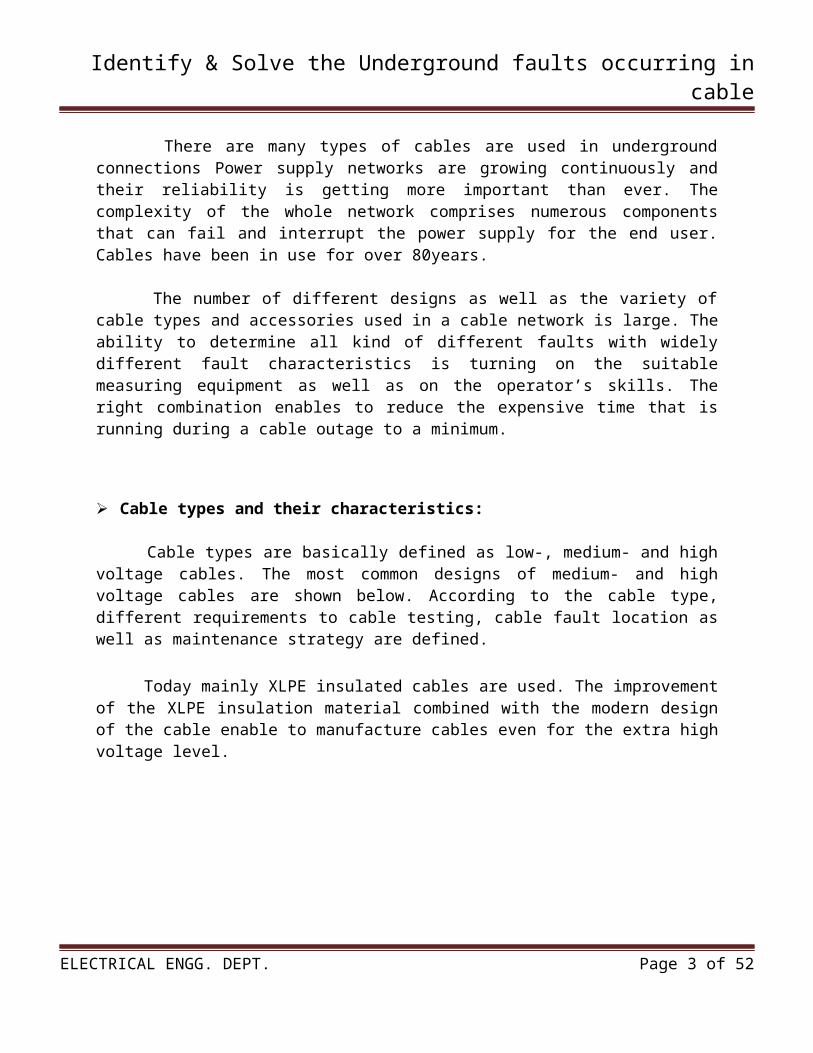
Cable types are basically defined as low-, medium- and high voltage cables. The most common designs of medium- and high voltage cables are shown below. According to the cable type, different requirements to cable testing, cable fault location as well as maintenance strategy are defined.
Today mainly XLPE insulated cables are used. The improvement of the XLPE insulation material combined with the modern design of the cable enable to manufacture cables even for the extra high voltage level.
ELECTRICAL ENGG. DEPT. Page 2 of 52
Identify & Solve the Underground faults occurring in cable
1.1.1 Single core, XLPE insulated medium voltage cables 6kV up to 36kV
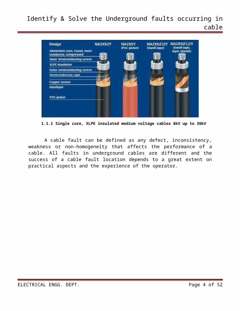
A cable fault can be defined as any defect, inconsistency, weakness or non-homogeneity that affects the performance of a cable. All faults in underground cables are different and the success of a cable fault location depends to a great extent on practical aspects and the experience of the operator.
1.1.21-core XLPE, 15kV 1.1.31-core XLPE 115Kv
To accomplish this, it is necessary to have personnel trained to test the cables successfully and to reduce their malfunctions. The development of refined techniques in the field of high voltage testing and diagnosis, in addition to the variety of methods for locating power cable faults, makes it imperative that qualified and experienced engineers and service operators be employee.
ELECTRICAL ENGG. DEPT. Page 3 of 52
Identify & Solve the Underground faults occurring in cable
1.2 INTRODUCTION ABOUT COMPANY
KrishakBharati Cooperative Limited’ (KRIBHCO) is an Indian cooperative society , that manufactures fertilizer, mainly urea. It registered under the Multi-State Cooperative Societies Act in 1985, and was promoted by the Government of India, and some agricultural co-operative societies spread all over the country. It main plant is located in Surat, Gujarat.
Oil & gas findings in Bombay High and South Basin triggered the birth of eight new generation fertilizer plants to fulfill the ever-growing food needs of the country. KRIBHCO was among the first two projects in the first pase.
KRIBHCO manufactures urea, ammonia Argon, bio-fertilizers, hybrid seeds & heavy water at Hazira in the State of Gujarat, on the bank of the Tapti River near Kawas village, 15 km from Surat and 20 km from the Surat Railway Station, on the Surat-Hazira State Highway.
HaziraFertilizer Complex has 2 Streams of Ammonia Plant and 4 Streams of Urea Plant. Annual re-assessed capacity for Urea and Ammonia is 1.729 million MT and 1.003 million MT respectively.
Production of Biofertilizerplant [1] commenced plant of 100 MT per year capacity was commissioned at Hazira in 1995. An additional capacity of 150 MT was added to that plant in 1998. Subsequently, two more Bio-fertilizer plants, each of 100 MT capacities, were installed at Varanasi, Uttar Pradesh and Lanja, Maharashtra in 2003 and 2004 respectively.
Dr. Chandrapal Singh Yadav has been chairman of KRIBHCO since 1996 under his leadership KRIBHCO achieved the turnover of Rs. 2400 crore in the financial year 2007-08. Sh. VaghjibhaiRugnathbhai Patel took charge as Chairman of KRIBHCO and Dr. Chandrapal Singh Yadav is acting as Vice-Chairman at present.
KRIBHCO had also entered into Logistics Business, Oman India Fertilizer Complex (OMIFCO), Diversification into Power Sector, Insurance Sector etc. OMIFCO is the first overseas JV project of the company in which KRIBHCO holds 25 % equity. Besides, KRIBHCO has also made realignment in its corporate strategy and internal operations revamping to meet the challenges in the liberalized/globalized economy. Illustration for this is turn-around of loss makingKrishakBharatiSeva Kendra (KBSKs) and Seed Processing Units (SPUs) into profit centers.
ELECTRICAL ENGG. DEPT. Page 4 of 52
Identify & Solve the Underground faults occurring in cable
Marketing Division of the society, besides marketing about 18.00 Lakhs MT of urea produced annually at our plant in HAZIRA since commencement of production in 1986, is also handling and marketing about 10.00 Lakhs MT of Urea produced by OMIFCO ( KRIBHCO is one of the promoter of the company) annually since 2005-06.
In 2006, KRIBHCO also acquired SahajanpurFertilizer Complex through its joint venture company KSFL (KRIBHCO holds 85% of the share in the JV), and about 10.00 Lakhs MT of urea produced annually by this plant is being marketed by KRIBHCO since 2006. At present KRIBHCO is marketing about 38.00 Lakhs MT of urea annually which is about 14% of the total urea consumption of the country. The marketing division of the society is fully geared up to market the likely additional quantities of about 5.00 Lakhs MT of urea from next year after revamp of our plant at HAZIRA.
The operation of fertilizer industry particularly indigenous manufacturers changed significantly on implementation of NPS-stage –III policy and implementation of NBS (from 01-04-2010). In Light of conducive and stable policy frame work, KRIBHCO is perusing import and marketing of other fertilizer material like DAP and MOP. The Society plans to import and market about 4.00 Lakhs MT of DAP during 2010-11. Society is planning to increase import of DAP and MOP to about 9.00 Lakhs MT annually in next 3 years.
To promote the organic agriculture in the country, Government has initiated several initiatives like promotion of use of bio-fertilizers, bio-compost etc. KRIBHCO has been promoting the use of bio-fertilisers since many years.
The society has three units to manufacture bio-fertilisers at Hazira (Gujarat), Varanasi (Uttar Pradesh) and Lanjha (Maharashtra). All four popular bio-fertilisersi.e. Rhizobium, Azotobactor, Azossprillium and Phosphate Soluble are produced and marketed by KRIBHCO. The Society has plans to sell around 1000 MT of bio-fertilisers during 2010-2011, which is likely to increase to about 1200 MT in next 3-5 years.
Organic Agriculture has emerged as a feasible option to concern relating to land degradations. As per the GOI directives, all fertilizer suppliers are expected topromote the use of Bio-Compost by involving actively in the marketing of the product. KRIBHCO has sufficient human resources and credible brand image to market Bio-compost. This will also help the society to generate additional margins. During the year 2010-2011 we plans to market about 19,000 MT of bio-compost which is expected to increase to about 50,000 MT in next 3 years.
In a nut shell KRIBHCO, world’s premier fertilizer producing cooperative has an outstanding track record to its credit in all spheres of its activities. KRIBHCO has fully imbibed the cooperative philosophy and has made sustained efforts towards promoting the cause of modern agriculture and cooperatives in the country. Kribhco stands for commitment sincerity and high standards ofexcellence.
In our endeavor towards achieving our goals we are impelled by the ideals set by our predecessors and the devotion and dedication of our employees.
ELECTRICAL ENGG. DEPT. Page 5 of 52
Identify & Solve the Underground faults occurring in cable
Salient Features of Kribhco:
17 th April, 1980 : kribhco was incorporated 5 th February, 1982 : Foundation stone laid at Hazira(Gujarat) November, 1985 : Urea production started May, 1991 : Seed production started August, 1995 : Bio-Fertilizers production started July, 2005 : OMIFCO started commercial production And 50% marketing of produced urea in India by KRIBHCO.
Product :
Urea Ammonia Bio-fertilizer Argon Seeds
Services:
Farmer’s Services KBSK KrishiPramarsh Kendra Kisan Helpline KrishiKarya Soil Testing Report
1.2.1 Layout of company
ELECTRICAL ENGG. DEPT. Page 6 of 52
Identify & Solve the Underground faults occurring in cable
Vision: To become a world class organization that represents the farmer community and maximizes their returns through specialization in agricultural inputs, rural need based products and other diversified businesses that maximize stakeholders value.
Mission: To act as a catalyst to agricultural and rural development by selecting,financingand managing projects that are bothsocially desirable and commercially profitable.
Objectives:
To strengthen cooperative system To enhance the urea installed capacity and increasing its market share To ensure optimum utilization of existing plant and machinery To diversify into other core sectors like Power, Port, Infrastructure, Rural Retail, etc Transfer of technology for modern farming and improving farmers'livelihood To educate and train farmers, provide free testing facilities for soil nutrients and irrigation
water
1.2.2 Growth of the company
ELECTRICAL ENGG. DEPT. Page 7 of 52

Identify & Solve the Underground faults occurring in cable
CHAPTER 02:- FLOW DIAGRAM OF
COMPANY AND PROJECT
2.1 FLOW DIAGRAM OF COMPANY
ELECTRICAL ENGG. DEPT. Page 8 of 52

Identify & Solve the Underground faults occurring in cable
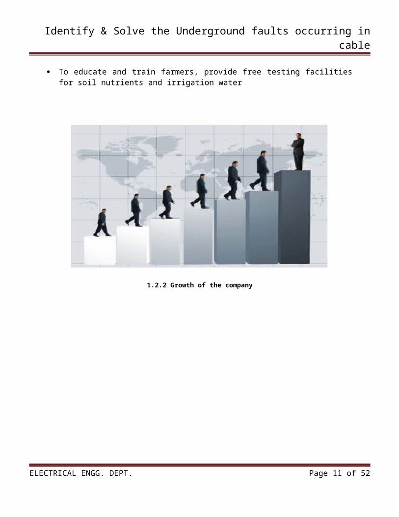
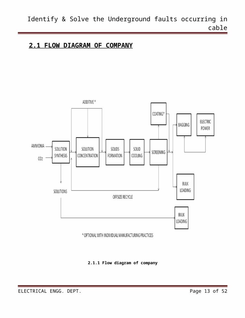
2.1.1 Flow diagram of company
2.2 DETAIL DESCRIPTION OF EACH BLOCK
ELECTRICAL ENGG. DEPT. Page 9 of 52
Identify & Solve the Underground faults occurring in cable
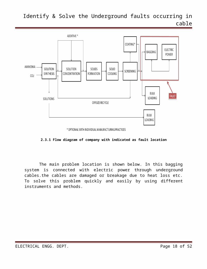
The process for manufacturing urea involves a combination of up to 7 major unit operations. These operations, illustrated by the flow diagram in Figure, are solution synthesis, solution concentration, solids formation, solids cooling, solids screening, solids coating and bagging, and/or bulk shipping.
The combination of processing steps is determined by the desired end products. For example,plants producing urea solution use only the solution formulation and bulk shipping operations. Facilities producing solid urea employ these 2 operations and various combinations of the remaining 5 operations, depending upon the specific end product being produced.
SOLUTION SYNTHESIS:
In the solution synthesis operation, ammonia (NH3) and carbon dioxide (CO2) are reacted to form ammonium carbamate (NH2CO2NH4). Typical operating conditions include temperatures from 180 to 200°C (356 to 392°F), pressures from 140 to 250 atmospheres (14,185 to 25,331 kilopascals) NH3:CO2 molar ratios from 3:1 to 4:1, and a retention time of 20 to 30 minutes. The carbamate is then dehydrated to yield 70 to 77 percent aqueous urea solution. These reactions are as follows:
2NH3 + CO2 NH2CO2NH4
NH2CO2NH4 NH2CONH2 + H2O
The urea solution can be used as an ingredient of nitrogen solution fertilizers, or it can be concentrated further to produce solid urea.
SOLUTION CONCENTRATION:
The 3 methods of concentrating the urea solution are vacuum concentration, crystallization, and atmospheric evaporation. The method chosen depends upon the level of biuret (NH2CONHCONH2) impurity allowable in the end product. Aqueous urea solution begins to decompose at 60°C (140°F) to biuret and ammonia. The most common method of solution concentration is evaporation.The concentration process furnishes urea "melt" for solids formation. Urea solids are produced from the urea melt by 2 basic methods: prilling and granulation.
SOLIDS FORMATION:
Prilling is a process by which solid particles are produced from molten urea. Molten urea is sprayed from the top of a prill tower. As the droplets fall through a countercurrent air flow, they cool and solidify into nearly spherical particles. There are 2 types of prill towers: fluidized bed and nonfluidized bed. The major difference is that a separate solids cooling operation may be required to produce agricultural grade prills in a nonfluidized bed prill tower.
ELECTRICAL ENGG. DEPT. Page 10 of 52
Identify & Solve the Underground faults occurring in cable
Granulation is used more frequently than prilling in producing solid urea for fertilizer. Granular urea is generally stronger than prilled urea, both in crushing strength and abrasion resistance.There are 2 solids are built up in layers on seed granules placed in a rotating drum granulator/cooler approximately 4.3 meters (14 feet) in diameter. Pan granulators also form the product in a layering process, but different equipment is used and pan granulators are not commonly used in the U. S.
SOLID COOLING:
The solids cooling operation is generally accomplished during solids formation, but for pan auxiliary rotary drums.
SCREENING:
The solids screening operation removes offsize product from solid urea. The offsize material may be returned to the process in the solid phase or be redissolved in water and returned to the solution concentration process.
COATING:
Clay coatings are used in the urea industry to reduce product caking and urea dust formation. The coating also reduces the nitrogen content of the product. The use of clay coating has diminished considerably, being replaced by injection of formaldehyde additives into the liquid or molten urea before solids formation. Formaldehyde reacts with urea to from methylenediurea, which is the conditioning agent. Additives reduce solids caking during storage and urea dust formation during transport and handling.
BAGGING & ELECTRIC POWER:
In bagging system the product is packed in a proper manner..Theelectric power system is connected with bagging stage of the process through underground cables. Bagging system is taken suuply from electric power to run the process continuosly.
BULK LOADING:
The majority of solid urea product is bulk shipped in trucks, enclosed railroad cars, or barges, but approximately 10 percent is bagged.
2.3DETAIL DESCRIPTION OF PROBLEM
ELECTRICAL ENGG. DEPT. Page 11 of 52

Identify & Solve the Underground faults occurring in cable
In this project there is problem related to this:-
There is bagging stage is connected with electric power through underground cables. Due to I2R loss, heat loss, there is chances of breakage or damage the cables. Due to this the cable get damage or break. Due to this problem the bagging process is stopped and the whole process is running slowely. We cannot solve this problem directly/easily, because the cables are under the ground. The main problem in this process is indicated as red mark.
2.3.1 Flow diagram of company with indicated as fault location
The main problem location is shown below. In this bagging system is connected with electric power through underground cables.the cables are damaged or breakage due to heat loss etc. To solve this problem quickly and easily by using different instruments and methods.
ELECTRICAL ENGG. DEPT. Page 12 of 52
Identify & Solve the Underground faults occurring in cable
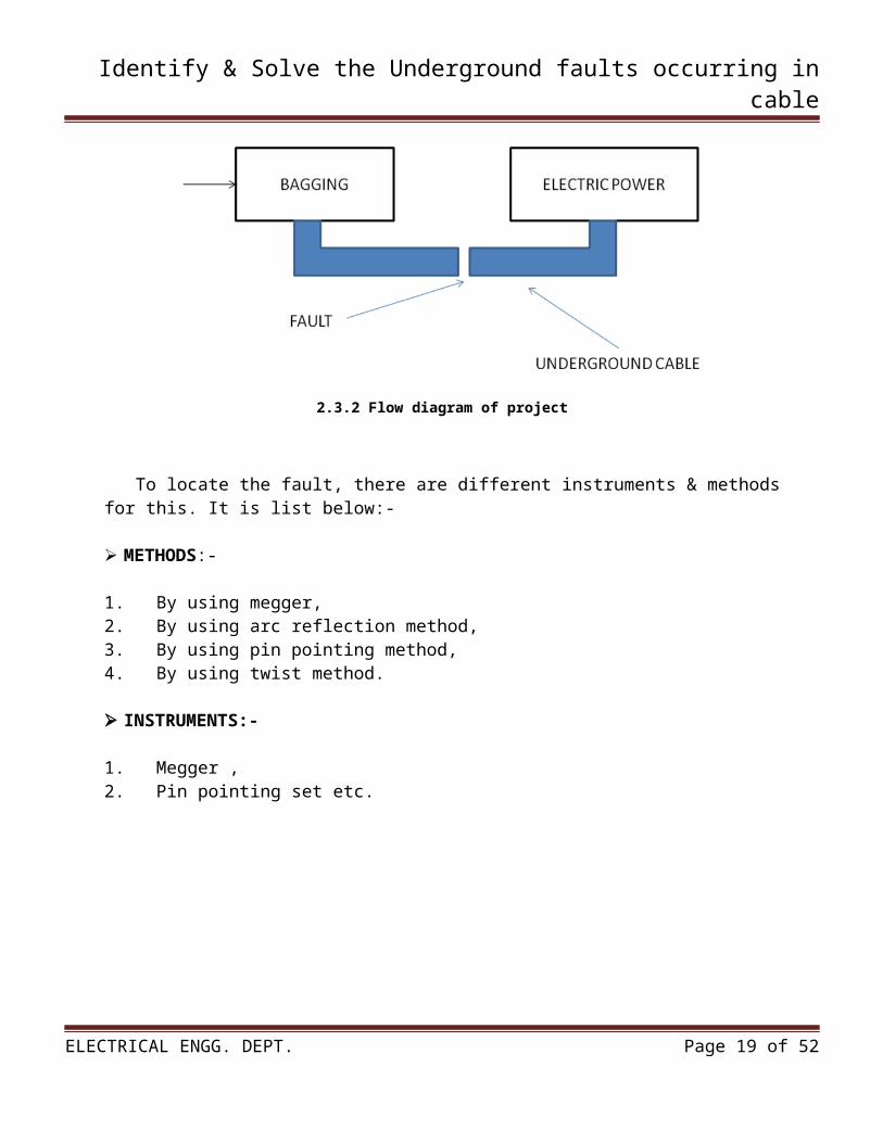
2.3.2 Flow diagram of project
To locate the fault, there are different instruments & methods for this. It is list below:-
METHODS:-
1. By using megger,2. By using arc reflection method,3. By using pin pointing method,4. By using twist method.
INSTRUMENTS:-
1. Megger ,2. Pin pointing set etc.
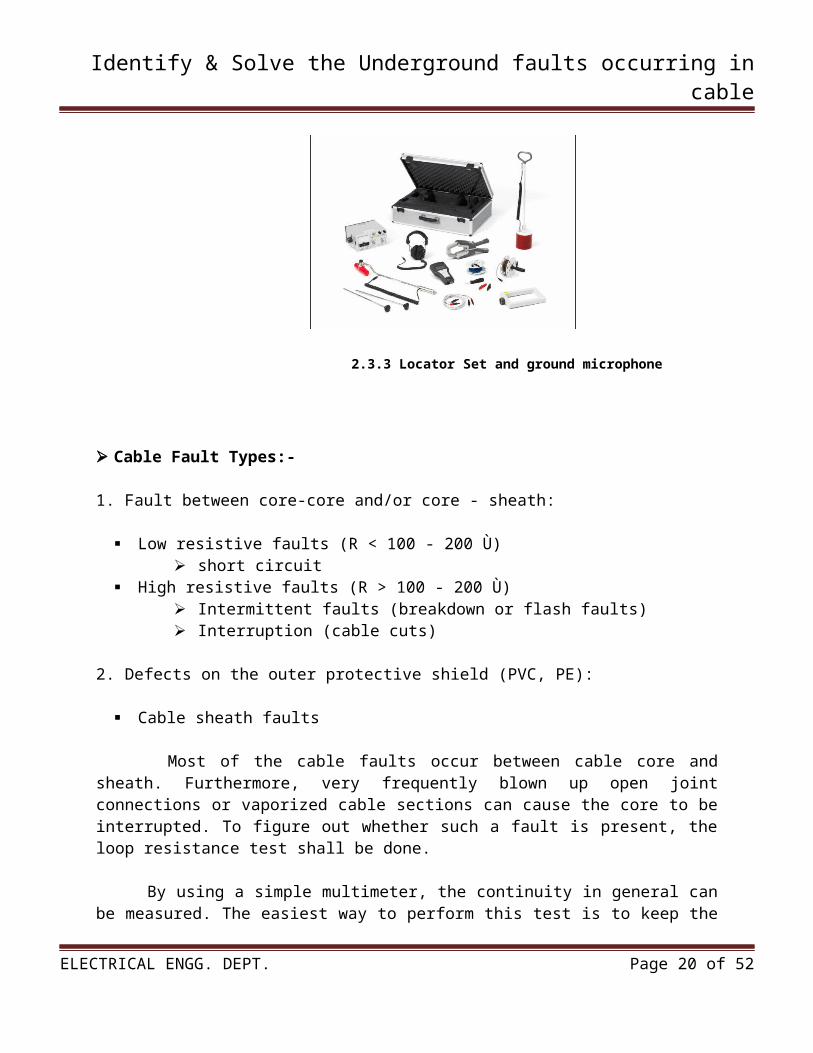
2.3.3 Locator Set and ground microphone
ELECTRICAL ENGG. DEPT. Page 13 of 52
Identify & Solve the Underground faults occurring in cable
Cable Fault Types:-
1. Fault between core-core and/or core - sheath:
Low resistive faults (R < 100 - 200 Ù) short circuit
High resistive faults (R > 100 - 200 Ù) Intermittent faults (breakdown or flash faults) Interruption (cable cuts)
2. Defects on the outer protective shield (PVC, PE):
Cable sheath faults
Most of the cable faults occur between cable core and sheath. Furthermore, very frequently blown up open joint connections or vaporized cable sections can cause the core to be interrupted. To figure out whether such a fault is present, the loop resistance test shall be done.
By using a simple multimeter, the continuity in general can be measured. The easiest way to perform this test is to keep the circuit breaker at the far end grounded. Corrosion of the cable sheath may increase the line resistance.
This is already an indication for possible part reflections in the TDR (TIME DOMAIN REFLECTOR) result. As a rough guidance, a line resistance of 0.7 Ohm/km can be considered as normal condition.
In dependence of the fault characteristic, the suitable cable fault prelocation and pinpointing methods need to be selected by the operator.
Probable faults in underground cables due to poor maintenance:
1. Temperature may increase due to over loading which affects the conducter and the insulation. This may result in earth fault or short circuit.
2. The cable may be damaged mechanically if care is not taken. This is converted in to the electrical fault.
3. Rain water if enters the cable at the weak point affects the insulating property and the armouring gets rusted.
4. The insulating property is reduced if oil leaks from the oil filled cables.
5. Moisture enters the cable through cable joint and affects insulating property when the cable joint is not properly maintained.
ELECTRICAL ENGG. DEPT. Page 14 of 52
Identify & Solve the Underground faults occurring in cable
CHAPTER 03:-DETAIL DESCRIPTION OF SOLUTION AND METHODS TO
INDICATE THE FAULT
ELECTRICAL ENGG. DEPT. Page 15 of 52
Identify & Solve the Underground faults occurring in cable
3.1 DETAIL DESCRIPTION OF SOLUTION
By using different instruments & methods we can locate the underground faults in cables. There is some procedure to locate the fault in cable.
Cable Fault Location Procedure:
Cable fault location as such has to be considered as a procedure covering the following steps and not being only one single step.
Fault Indication Disconnecting and Earthing Fault Analyses and Insulation Test Cable Fault Prelocation Cable Route Tracing Precise Cable Fault Location (Pinpointing) Cable Identification Fault Marking and Repair Cable Testing and Diagnosis Switch on Power
There are many methods to locate the fault, but we choose the four methods to locate the underground fault in cable. They are listed below:-
1. By using megger,2. By using arc reflection method,3. By using pin pointing method,4. By using twist method.
All the methods are briefly explained below:
3.2 BY USING MEGGER
PRINCIPLE OF MEGGER:
Megger works on the principle of ohm’s law. First of all its generates high voltage through its generator or D.C. /A.C. converter and voltage multiplier.
More the voltage generated by generator more accurate the results. It calculates the insulation resistance of the circuit under test by supplying high voltage of the ends.
When the circuit has high internal resistance more voltage drop and less current flows and vice versa. It supplies the voltage at the ratings of 1KV, 2KV, 5KV, 10KV, 20KV & so on.
ELECTRICAL ENGG. DEPT. Page 16 of 52
Identify & Solve the Underground faults occurring in cable
More the voltage rating megger will be able to measure millions of ohm’s and up to infinity level.
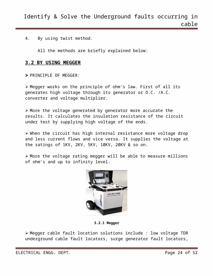
3.2.1 Megger
Megger cable fault location solutions include : low voltage TDR underground cable fault locators, surge generator fault locators, cable fault pinpointing, high voltage DC test sets and high voltage (11kV-33kV-66kV-132kV) underground cable fault locators.
By using megger we can locate the underground faults in cable. As shown in figure two leads of megger are connected to cable. If the cable is faulty it’s indicated on megger display.
There are different types of megger used to locate the faults. We used the Megger-PPL20-1500 series to locate the fault. It is very simple & easy method to locate the fault.
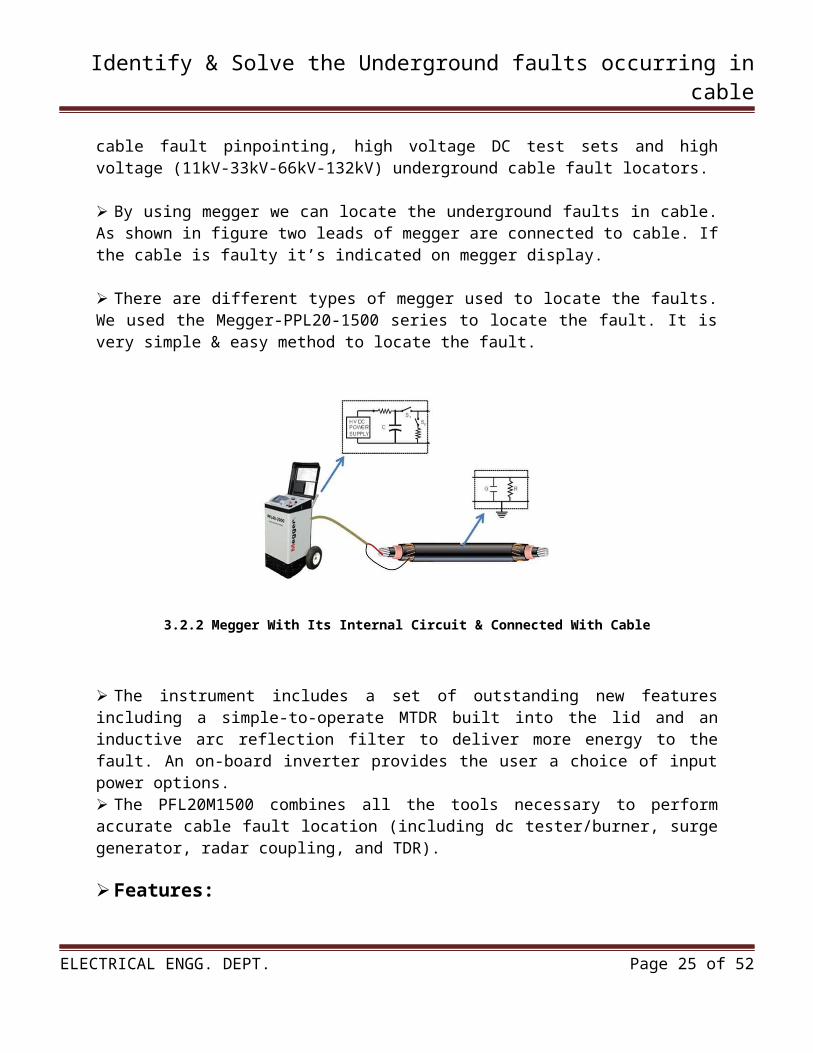
3.2.2 Megger With Its Internal Circuit & Connected With Cable
The instrument includes a set of outstanding new features including a simple-to-operate MTDR built into the lid and an inductive arc reflection filter to deliver more energy to the fault. An on-board inverter provides the user a choice of input power options. The PFL20M1500 combines all the tools necessary to perform accurate cable fault location (including dc tester/burner, surge generator, radar coupling, and TDR).
ELECTRICAL ENGG. DEPT. Page 17 of 52
Identify & Solve the Underground faults occurring in cable
Features:
New style MTDR is mounted in the lid for easier viewing with a large, bright screen Inductive arc reflection filter delivers more energy where it's needed On-board inverter provides a choice of power options Multiple fault locating techniques:
a. Arc Reflection Method b. Time Domain Reflectometry (Pulse Echo) c. Impulse Current d. High Voltage Surge e. Proof and Burn
3.3 BY USING ARC REFLECTION METHOD
Use of the arc reflection method combined with a high capacitance surge generator and state-of-the-art pinpointing devices for underground cable fault locating will find faults in less time and with less risk of damaging good cable than classical techniques.
The combination of these components is referred to as the characteristic impedance (Z0) of the cable. If every increment of cable is perfect and exactly the same, all components of the equivalent circuit of every foot are also exactly the same.
This perfect run of cable will produce no reflections until the end of the cable appears.
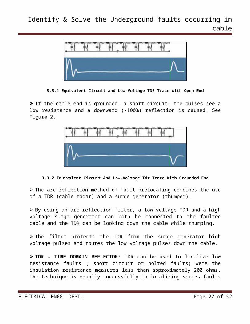
At the end of the cable the pulses see a high impedance, an open circuit, causing an upward (+100%) reflection. See Figure 1.
3.3.1 Equivalent Circuit and Low-Voltage TDR Trace with Open End
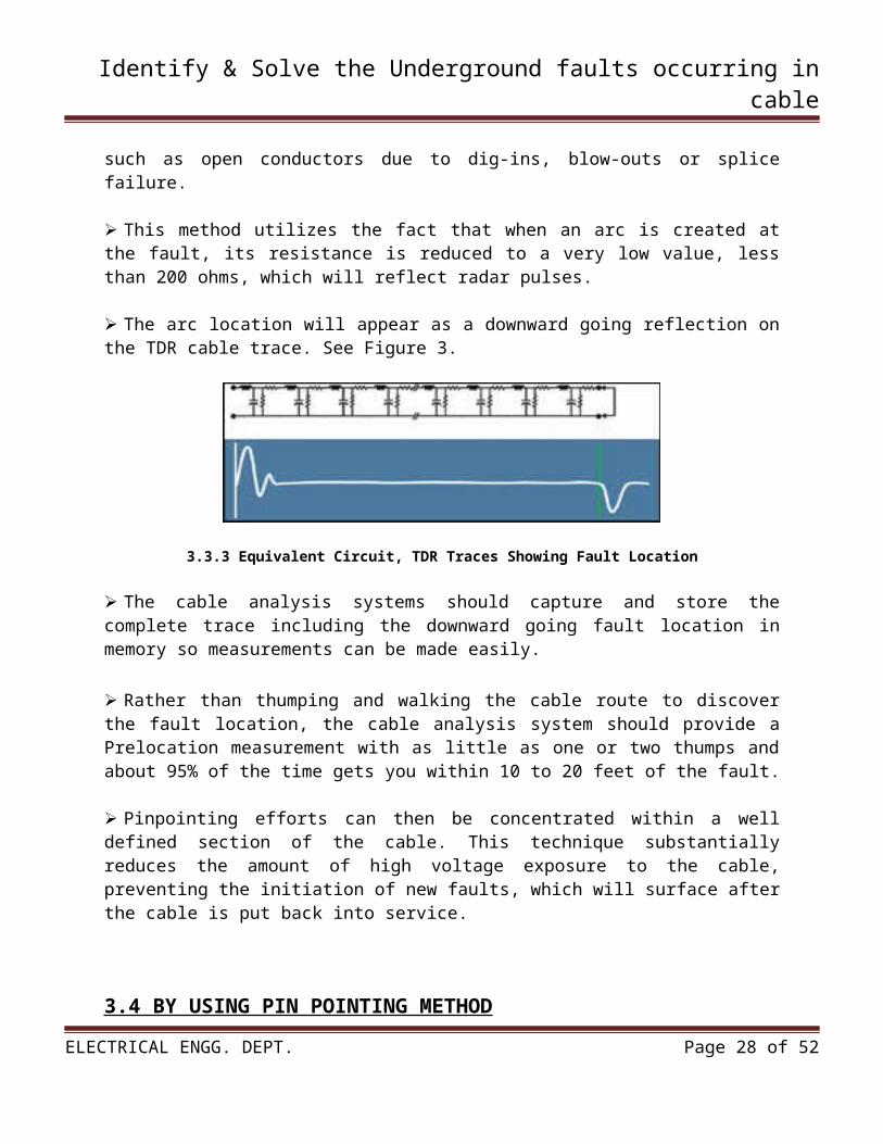
If the cable end is grounded, a short circuit, the pulses see a low resistance and a downward (-100%) reflection is caused. See Figure 2.
ELECTRICAL ENGG. DEPT. Page 18 of 52
Identify & Solve the Underground faults occurring in cable
3.3.2 Equivalent Circuit And Low-Voltage Tdr Trace With Grounded End
The arc reflection method of fault prelocating combines the use of a TDR (cable radar) and a surge generator (thumper).
By using an arc reflection filter, a low voltage TDR and a high voltage surge generator can both be connected to the faulted cable and the TDR can be looking down the cable while thumping.
The filter protects the TDR from the surge generator high voltage pulses and routes the low voltage pulses down the cable.
TDR - TIME DOMAIN REFLECTOR: TDR can be used to localize low resistance faults ( short circuit or bolted faults) were the insulation resistance measures less than approximately 200 ohms. The technique is equally successfully in localizing series faults such as open conductors due to dig-ins, blow-outs or splice failure.
This method utilizes the fact that when an arc is created at the fault, its resistance is reduced to a very low value, less than 200 ohms, which will reflect radar pulses.
The arc location will appear as a downward going reflection on the TDR cable trace. See Figure 3.
3.3.3 Equivalent Circuit, TDR Traces Showing Fault Location
The cable analysis systems should capture and store the complete trace including the downward going fault location in memory so measurements can be made easily.
ELECTRICAL ENGG. DEPT. Page 19 of 52
Identify & Solve the Underground faults occurring in cable
Rather than thumping and walking the cable route to discover the fault location, the cable analysis system should provide a Prelocation measurement with as little as one or two thumps and about 95% of the time gets you within 10 to 20 feet of the fault.
Pinpointing efforts can then be concentrated within a well defined section of the cable. This technique substantially reduces the amount of high voltage exposure to the cable, preventing the initiation of new faults, which will surface after the cable is put back into service.
3.4 BY USING PIN POINTING METHOD
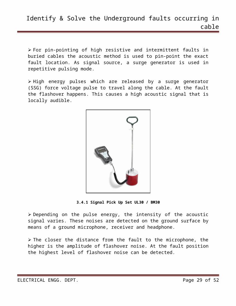
For pin-pointing of high resistive and intermittent faults in buried cables the acoustic method is used to pin-point the exact fault location. As signal source, a surge generator is used in repetitive pulsing mode.
High energy pulses which are released by a surge generator (SSG) force voltage pulse to travel along the cable. At the fault the flashover happens. This causes a high acoustic signal that is locally audible.
3.4.1 Signal Pick Up Set UL30 / BM30
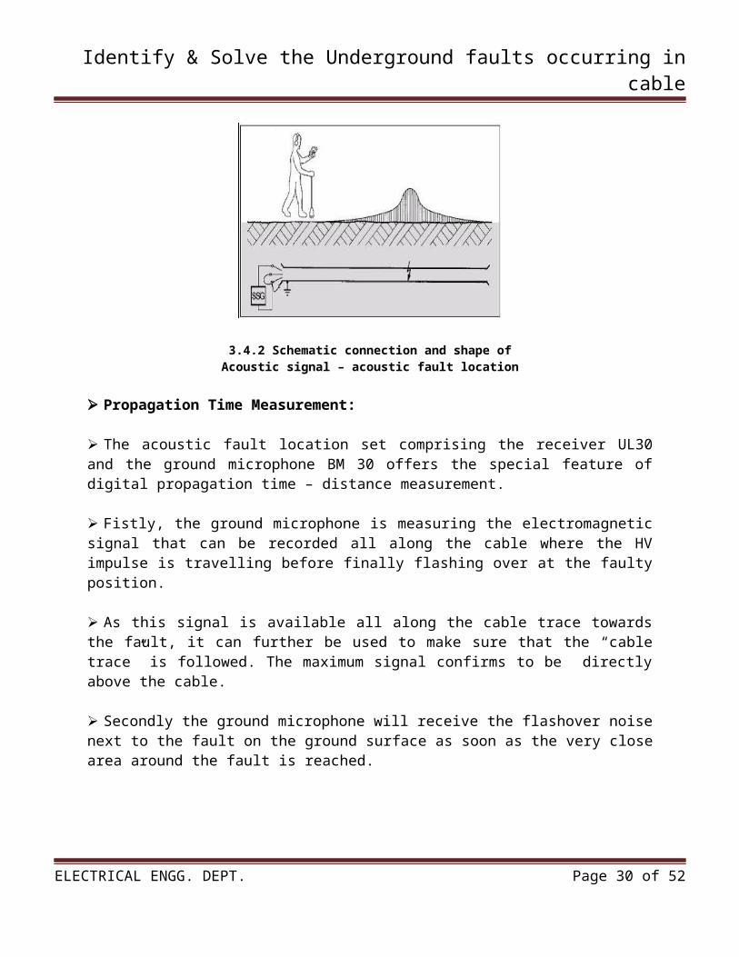
Depending on the pulse energy, the intensity of the acoustic signal varies. These noises are detected on the ground surface by means of a ground microphone, receiver and headphone.
The closer the distance from the fault to the microphone, the higher is the amplitude of flashover noise. At the fault position the highest level of flashover noise can be detected.
ELECTRICAL ENGG. DEPT. Page 20 of 52
Identify & Solve the Underground faults occurring in cable
3.4.2 Schematic connection and shape ofAcoustic signal – acoustic fault location
Propagation Time Measurement:
The acoustic fault location set comprising the receiver UL30 and the ground microphone BM 30 offers the special feature of digital propagation time – distance measurement.
Fistly, the ground microphone is measuring the electromagnetic signal that can be recorded all along the cable where the HV impulse is travelling before finally flashing over at the faulty position.
As this signal is available all along the cable trace towards the fault, it can further be used to make sure that the “cable trace” is followed. The maximum signal confirms to be directly above the cable.
Secondly the ground microphone will receive the flashover noise next to the fault on the ground surface as soon as the very close area around the fault is reached.
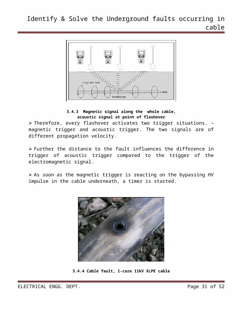
3.4.3 Magnetic signal along the whole cable,acoustic signal at point of flashover
ELECTRICAL ENGG. DEPT. Page 21 of 52
Identify & Solve the Underground faults occurring in cable
Therefore, every flashover activates two trigger situations. – magnetic trigger and acoustic trigger. The two signals are of different propagation velocity.
Further the distance to the fault influences the difference in trigger of acoustic trigger compared to the trigger of the electromagnetic signal.
As soon as the magnetic trigger is reacting on the bypassing HV impulse in the cable underneath, a timer is started.
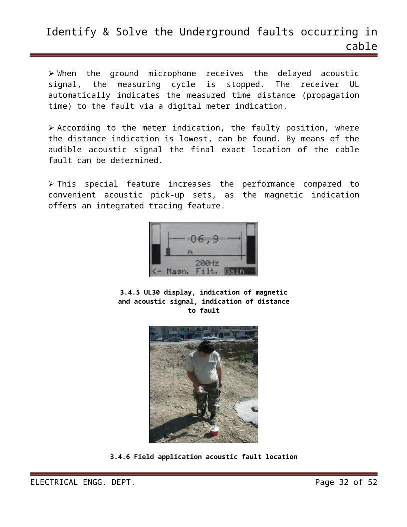
3.4.4 Cable fault, 1-core 11kV XLPE cable
When the ground microphone receives the delayed acoustic signal, the measuring cycle is stopped. The receiver UL automatically indicates the measured time distance (propagation time) to the fault via a digital meter indication.
According to the meter indication, the faulty position, where the distance indication is lowest, can be found. By means of the audible acoustic signal the final exact location of the cable fault can be determined.
This special feature increases the performance compared to convenient acoustic pick-up sets, as the magnetic indication offers an integrated tracing feature.
3.4.5 UL30 display, indication of magneticand acoustic signal, indication of distance
to fault
ELECTRICAL ENGG. DEPT. Page 22 of 52
Identify & Solve the Underground faults occurring in cable
3.4.6 Field application acoustic fault location
3.5 BY USING TWIST METHOD
The twist method can be applied for pin-pointing of low resistive faults in twisted cables. In this method, the effect that the cores are longitudinally turned-in is used.
The basic signal used is a high frequency audio signal causing equivalent signals like used for cable route tracing. Differing to route tracing, where the signal is sent through a healthy core, for this method the signal is forced over the fault.
Therefore the application is depending on the fault resistance. Higher resistive faults request a very powerful audio frequency generator.
The audio frequency signal is passing back and forth in the same cable up to the fault where the signal faces the return point.
Due to the twist, what means the steadily change of geometrical position of the cores in the cable, the maxima and minima of signal resulting can be followed on the surface.
The twist length in the cable is depending on the type of cable but is roughly 1meter. According to this, the point where the signal ends can be determined as the cable fault.
An audio frequency signal (2 kHz) with high current (10 to 30 A) is supplied into the faulty pair of cores. Despite reverse current directions, a resulting magnetic field can be measured above ground surface.
Powerful audio frequency generators (600 VA) with incorporated reactive current compensation are needed for successful use in practical application.
ELECTRICAL ENGG. DEPT. Page 23 of 52
Identify & Solve the Underground faults occurring in cable
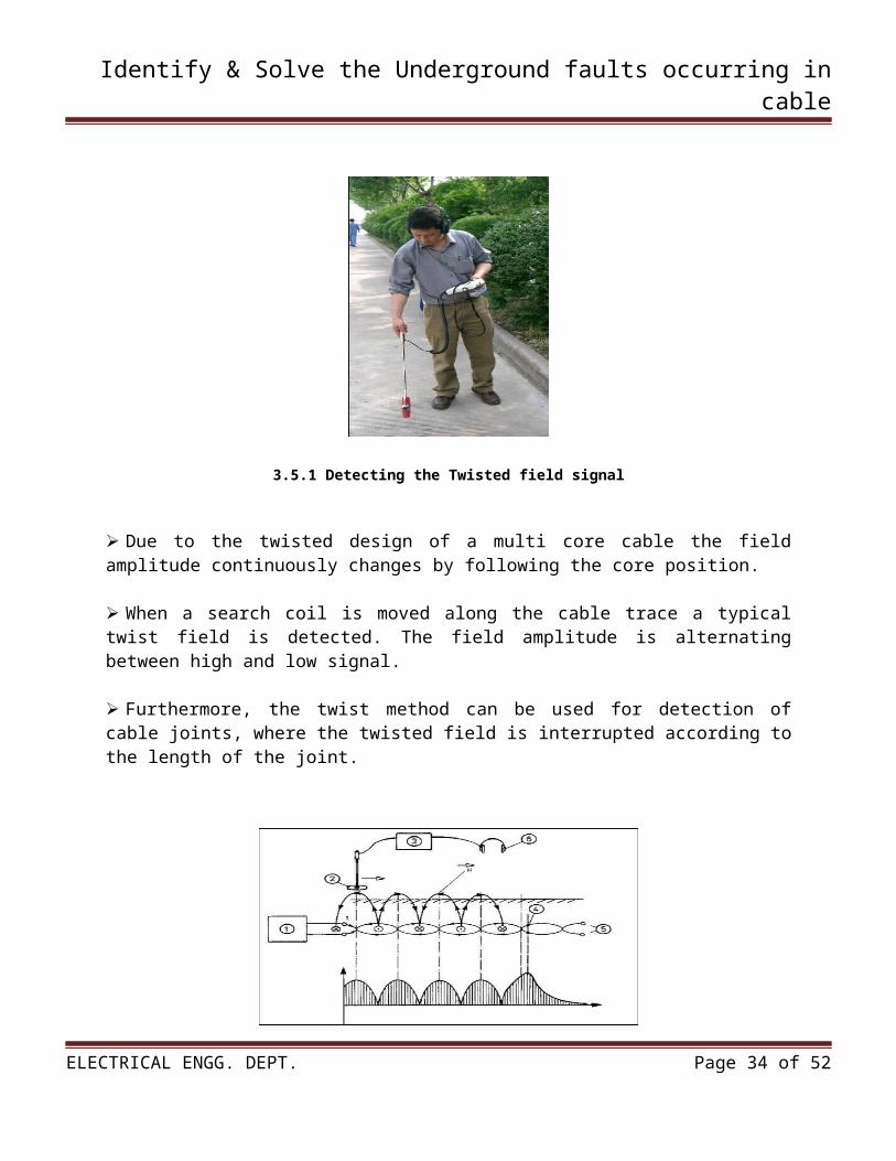
3.5.1 Detecting the Twisted field signal
Due to the twisted design of a multi core cable the field amplitude continuously changes by following the core position.
When a search coil is moved along the cable trace a typical twist field is detected. The field amplitude is alternating between high and low signal.
Furthermore, the twist method can be used for detection of cable joints, where the twisted field is interrupted according to the length of the joint.
3.5.2 Signal sequence Twist Method
1. Audio frequency generator2. surge coil3. receiver4. low resistive fault5. open cable end6. head phone
ELECTRICAL ENGG. DEPT. Page 24 of 52
Identify & Solve the Underground faults occurring in cable
The twist method offers a major advantage in T-branched networks as the twist signal is always in direction to the fault.
All healthy cable branches give a continuous low signal. The twist signal disappears as soon as the fault has been passed.
The twist method is most successful if the fault between the two cores is low resistance (< 2 Ù).
If the fault is conductive to the metal screen of the cable, the fault finding becomes more complicated. If then the metal screen is separated from ground, the twist method can be applied as well.
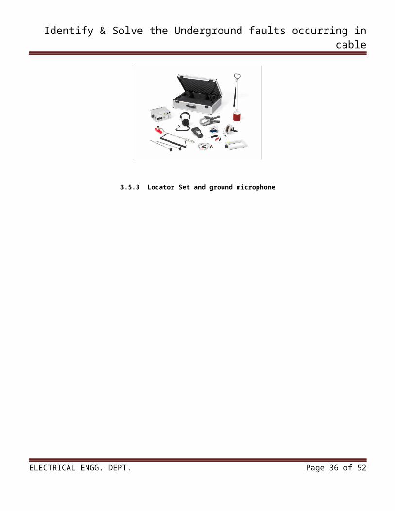
Locator set: Based on the multi receiver UL – the universal fault and cable locating set can be used for:
Cable route tracing. Twist method in combination with600VA audio frequency generator. Step voltage method with sheath faultlocation accessories. Acoustic fault location in combinationwith the ground microphone BM.
3.5.3 Locator Set and ground microphone
ELECTRICAL ENGG. DEPT. Page 25 of 52

Identify & Solve the Underground faults occurring in cable
CHAPTER 04:- TYPES AND CAUSES OF FAULT IN UNDERGROUND
CABLES
4.1 TYPES OF FAULTS IN UNDERGROUND CABLES
ELECTRICAL ENGG. DEPT. Page 26 of 52
Identify & Solve the Underground faults occurring in cable
Cables are generally laid directly in the ground or in ducts in the underground distribution system. For this reason, there are little chances of faults in underground cables. However, if a fault does occur, it is difficult to locate and repair the fault because conductors are not visible. Nevertheless, the following are the faults most likely to occur in underground cables:
1. Open-circuit fault2. Short-circuit fault3. Earth fault.
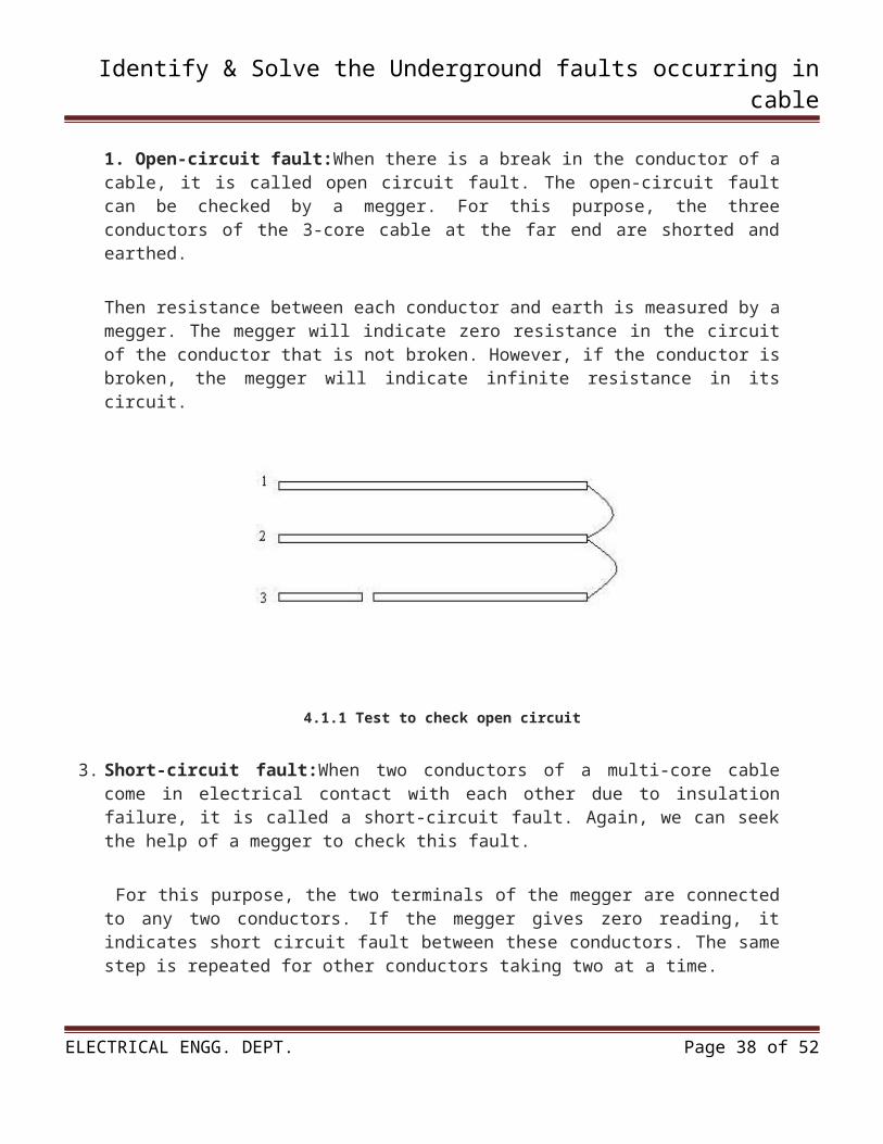
1. Open-circuit fault:When there is a break in the conductor of a cable, it is called open circuit fault. The open-circuit fault can be checked by a megger. For this purpose, the three conductors of the 3-core cable at the far end are shorted and earthed.
Then resistance between each conductor and earth is measured by a megger. The megger will indicate zero resistance in the circuit of the conductor that is not broken. However, if the conductor is broken, the megger will indicate infinite resistance in its circuit.
4.1.1 Test to check open circuit
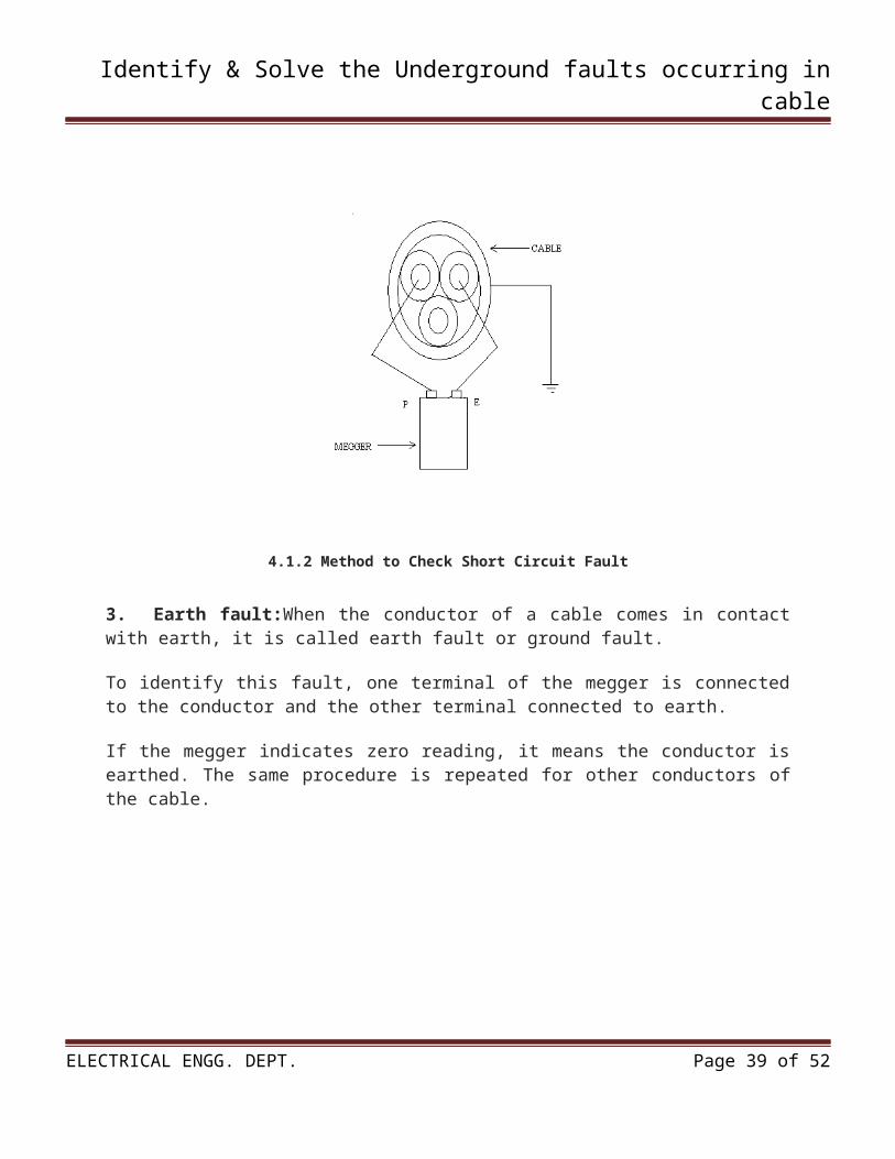
3. Short-circuit fault:When two conductors of a multi-core cable come in electrical contact with each other due to insulation failure, it is called a short-circuit fault. Again, we can seek the help of a megger to check this fault.
For this purpose, the two terminals of the megger are connected to any two conductors. If the megger gives zero reading, it indicates short circuit fault between these conductors. The same step is repeated for other conductors taking two at a time.
ELECTRICAL ENGG. DEPT. Page 27 of 52
Identify & Solve the Underground faults occurring in cable
4.1.2 Method to Check Short Circuit Fault
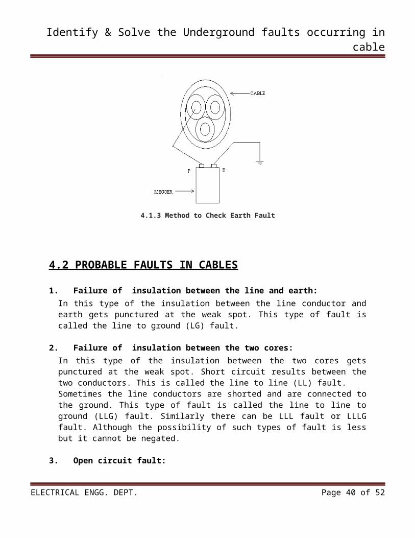
3. Earth fault:When the conductor of a cable comes in contact with earth, it is called earth fault or ground fault.
To identify this fault, one terminal of the megger is connected to the conductor and the other terminal connected to earth.
If the megger indicates zero reading, it means the conductor is earthed. The same procedure is repeated for other conductors of the cable.
4.1.3 Method to Check Earth Fault
ELECTRICAL ENGG. DEPT. Page 28 of 52
Identify & Solve the Underground faults occurring in cable
4.2 PROBABLE FAULTS IN CABLES
1. Failure of insulation between the line and earth: In this type of the insulation between the line conductor and earth gets punctured at the weak spot. This type of fault is called the line to ground (LG) fault.
2. Failure of insulation between the two cores:In this type of the insulation between the two cores gets punctured at the weak spot. Short circuit results between the two conductors. This is called the line to line (LL) fault.Sometimes the line conductors are shorted and are connected to the ground. This type of fault is called the line to line to ground (LLG) fault. Similarly there can be LLL fault or LLLG fault. Although the possibility of such types of fault is less but it cannot be negated.
3. Open circuit fault:Sometimes one or more cores of the cable break. This type of fault is called the open circuit fault.
4.3 CAUSES OF FAULTS IN CABLES
Fault in underground cable can occur due to the following reasons:
1. Sheath can break when one digs the ground without knowing that there is cable beneath the ground. The moisture can enter the insulation and it results in line to ground fault or line to line fault.
2. When the cable is laid near the railway line, cracks may develop in the sheath due to continuous vibrations. Insulation gets punctured due to the entry of moisture and it results in line to ground or line to line fault.
3. When the soil near the cable is of chemical salt it damages the exterior of the cable and after sometimes the sheath is damaged and the faults discussed above may result.
4. Fault can occur in cable due to excessive die electric stress on insulation continuous overload, prolonged short circuit, poor heat dissipation etc.
ELECTRICAL ENGG. DEPT. Page 29 of 52
Identify & Solve the Underground faults occurring in cable
CHAPTER 05:- METHODS TO CHECK THE FAULTS IN UNDERGROUND AND PROJECT CIRCUIT DETAILS
ELECTRICAL ENGG. DEPT. Page 30 of 52
Identify & Solve the Underground faults occurring in cable
5.1 LOCALIZATION CABLE FAULT TEST
Murray loop test, Varley loop test and Pulse Echo test are simple and basic method to localize cable fault testing. This method usedbasic equipment that obtained easily.
These tests are performed for the location of either an earth fault orshort circuit fault in underground cable.
In these tests theresistance of fault does not affect the results obtained except when the resistance of fault is very high.
There are two loop tests usually used and are known as MurrayLoop and Varley Loop Test.
Murray Loop Test:
The connection diagrams to locate earth fault and short circuit faultby Murray loop test method are shown in Figure 8.1 respectively.
Asalready said Wheatstone bridge principle is used in these tests. Pand Q are two ratio arms consisting of step resistors or slide wire, G is a galvanometer, E is a battery and S1 is a battery key.
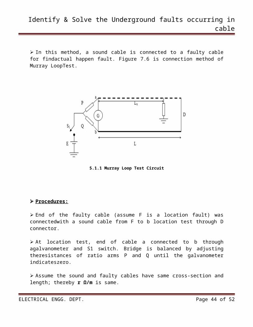
In this method, a sound cable is connected to a faulty cable for findactual happen fault. Figure 7.6 is connection method of Murray LoopTest.
5.1.1 Murray Loop Test Circuit
ELECTRICAL ENGG. DEPT. Page 31 of 52
Identify & Solve the Underground faults occurring in cable
Procedures:
End of the faulty cable (assume F is a location fault) was connectedwith a sound cable from F to b location test through D connector.
At location test, end of cable a connected to b through agalvanometer and S1 switch. Bridge is balanced by adjusting theresistances of ratio arms P and Q until the galvanometer indicateszero.
Assume the sound and faulty cables have same cross-section and length; thereby r Ω/m is same.
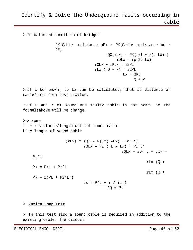
In balanced condition of bridge:
QX(Cable resistance aF) = PX(Cable resistance bd + DF) QX(rLx) = PX[ rl + r(L-Lx) ] rQLx = rp(2L-Lx) rQLx + rPLx = r2PL rLx ( Q + P) = r2PL Lx = 2PL Q + P
If L be known, so Lx can be calculated, that is distance of cablefault from test station.
If L and r of sound and faulty cable is not same, so the formulaabove will be change.
Assumer’ = resistance/length unit of sound cableL’ = length of sound cable
(rLx) * (Q) = P[ r(L-Lx) + r’L’] rQLx = Pr ( L – Lx) + Pr’L’
rQLx – rp( L – Lx) = Pr’L’ rLx (Q + P) = PrL + Pr’L’ rLx (Q + P) = r(PL + Pr’L’)
Lx = P(L + r’/ rl’) (Q + P)
Varley Loop Test
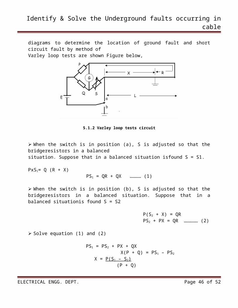
In this test also a sound cable is required in addition to the existing cable. The circuit diagrams to determine the location of ground fault and short circuit fault by method of Varley loop tests are shown Figure below,
ELECTRICAL ENGG. DEPT. Page 32 of 52
Identify & Solve the Underground faults occurring in cable
5.1.2 Varley loop tests circuit
When the switch is in position (a), S is adjusted so that the bridgeresistors in a balanced situation. Suppose that in a balanced situation isfound S = S1.
PxS1= Q (R + X)PS1 = QR + QX ………… (1)
When the switch is in position (b), S is adjusted so that the bridgeresistors in a balanced situation. Suppose that in a balanced situationis found S = S2
P(S2 + X) = QR PS2 + PX = QR …………… (2)
Solve equation (1) and (2)
PS1 = PS2 + PX + QX X(P + Q) = PS1 – PS2
X = P(S1 – S2) (P + Q)
ELECTRICAL ENGG. DEPT. Page 33 of 52
Identify & Solve the Underground faults occurring in cable
5.2 PROJECT CIRCUITS DETAILS
5.2.1 INVISIBLE BROKEN WIRE DETECTOR
Portable loads such as video cameras, halogen flood lights, electrical irons, hand drillers, grinders, cutters and in underground cables are powered by connecting long 2- or 3-core cables to the mains plug.
Due to prolonged usage, the power cord wires are subjected to mechanical strain and stress, which can lead to internal snapping of wires at any point.
In such a case most people go for replacing the core/cable, as finding the exact location of a broken wire is difficult.
In 3-core cables, it appears almost impossible to detect a broken wire and the point of break without physically disturbing all the three wires that are concealed in a PVC jacket.
The circuit presented here can easily and quickly detect a broken/faulty wire and its breakage point in 1-core, 2-core, and 3-core cables without physically disturbing wires.
It is built using hex inverter CMOS CD4069. Gates N3 and N4 are used as a pulse generator that oscillates at around 1000 Hz in audio range.
The frequency is determined by timing components comprising resistors R3 and R4, and capacitor C1. Gates N1 and N2 are used to sense the presence of 230V AC field around the live wire and buffer weak AC voltage picked from the test probe.
The voltage at output pin 10 of gate N2 can enable or inhibit the oscillator circuit. When the test probe is away from any high-voltage AC field, output pin 10 of gate N2 remains low.
As a result, diode D3 conducts and inhibits the oscillator circuit from oscillating. Simultaneously, the output of gate N3 at pin 6 goes ‘low’ to cut off transistor T1.
As a result, LED1 goes off. When the test probe is moved closer to 230V AC, 50Hz mains live wire, during every positive half cycle, output pin 10 of gate N2 goes high.
Thus during every positive half-cycle of the mains frequency, the oscillator circuit is allowed to oscillate at around 1 kHz, making red LED (LED1) to blink. (Due to the persistence of vision, the LED appears to be glowing continuously.)
This type of blinking reduces consumption of the current from button cells used for power supply. A 3V DC supply is sufficient for powering the whole circuit.
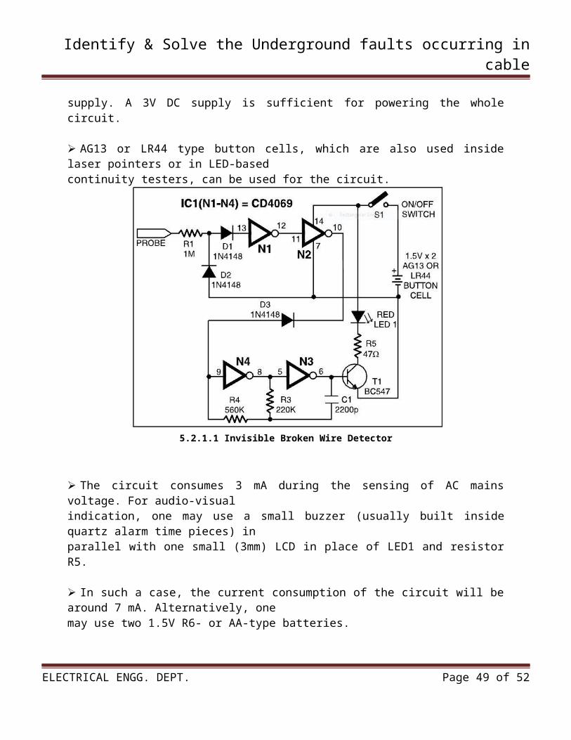
AG13 or LR44 type button cells, which are also used inside laser pointers or in LED-based continuity testers, can be used for the circuit.
ELECTRICAL ENGG. DEPT. Page 34 of 52
Identify & Solve the Underground faults occurring in cable
5.2.1.1 Invisible Broken Wire Detector
The circuit consumes 3 mA during the sensing of AC mains voltage. For audio-visual indication, one may use a small buzzer (usually built inside quartz alarm time pieces) in parallel with one small (3mm) LCD in place of LED1 and resistor R5.
In such a case, the current consumption of the circuit will be around 7 mA. Alternatively, one may use two 1.5V R6- or AA-type batteries.
Using this gadget, one can also quickly detect fused small filament bulbs in serial loops powered by 230V AC mains. The whole circuit can be accommodated in a small PVC pipe and used as a handy broken-wire detector.
Before detecting broken faulty wires, take out any connected load and find out the faulty wire first by continuity method using any multimeter or continuity tester.
Then connect 230V AC mains live wire at one end of the faulty wire, leaving the other end free. Connect neutral terminal of the mains AC to the remaining wires at one end.
However, if any of the remaining wires is also found to be faulty, then both ends of these wires are connected to neutral.
For single-wire testing, connecting neutral only to the live wire at one end is sufficient to detect the breakage point. In this circuit, a 5cm (2-inch) long, thick, single-strand wire is used as the test probe.
ELECTRICAL ENGG. DEPT. Page 35 of 52
Identify & Solve the Underground faults occurring in cable
To detect the breakage point, turn on switch S1 and slowly move the test probe closer to the faulty wire, beginning with the input point of the live wire and proceeding towards its other end.
LED1 starts glowing during the presence of AC voltage in faulty wire. When the breakage point is reached, LED1 immediately extinguishes due to the non-availability of mains AC voltage.
The point where LED1 is turned off is the exact broken-wire point. While testing a broken 3-core rounded cable wire, bend the probe’s edge in the form of ‘J’ to increase its sensitivity and move the bent edge of the test probe closer over the cable.
During testing avoid any strong electric field close to the circuit to avoid false detection.
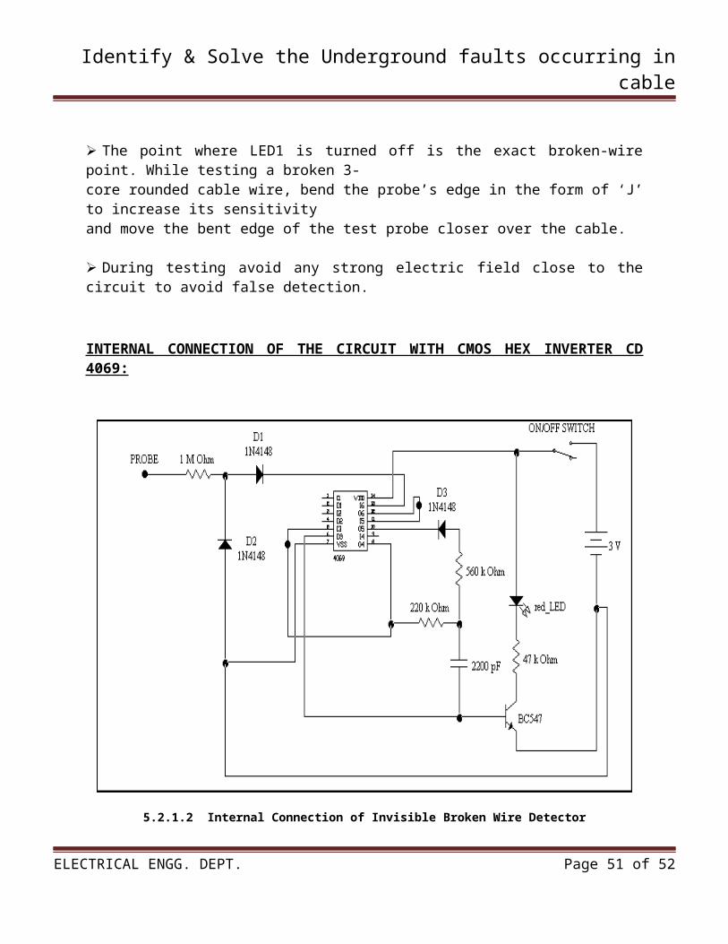
INTERNAL CONNECTION OF THE CIRCUIT WITH CMOS HEX INVERTER CD 4069:
5.2.1.2 Internal Connection of Invisible Broken Wire Detector
ELECTRICAL ENGG. DEPT. Page 36 of 52
Identify & Solve the Underground faults occurring in cable
5.2.2 COMPONENTS USED IN CIRCUIT
1. CMOS HEX INVERTER CD 4069:
The CD4069UB consists of six inverter circuits and is manufacturedusing complementary MOS (CMOS) to achievewide power supply operating range, low power consumption,high noise immunity, and symmetric controlled riseand fall times.
This device is intended for all general purpose inverterapplications where the special characteristics of theMM74C901, MM74C907, and CD4049A Hex Inverter/Buffersare not required.
In those applications requiring largernoise immunity the MM74C14 or MM74C914 Hex SchmittTrigger is suggested.
All inputs are protected from damage due to static dischargeby diode clamps to VDD and VSS.
Contains 6 inverter Circuits made using complimentary MOS Wide supply Voltage range :3 V – 15V High Noise Immunity: 45VDD type Low power TTL compatibility: Fan out of driving 74L Operating Temperature Range(TA): -55C to +125C
5.2.2.1 CMOS HEX INVERTER CD 4069 5.2.2.2 Schematic Diagram CMOS HEX INVERTER CD4069
ELECTRICAL ENGG. DEPT. Page 37 of 52
Identify & Solve the Underground faults occurring in cable
Features:
Wide supply voltage range: 3.0V to 15V High noise immunity: 0.45 VDD typ. Low power TTL compatibility: Fan out of 2 driving 74Lor 1 driving 74LS Equivalent to MM74C04
1. IN4148 High speed switching diodes:
High switching speed: max. 4 ns General application Continuous reverse voltage: max. 100V Repetitive peak reverse voltage: max.100V Repetitive peak forward current: Max. 450 mA
2. BC547 Transistor :
A component with three terminals B (Base), C (collector),E (Emitter). A Drawing of a BC547C transistor
5.2.2.3 BC547 Transistor
3. Resistors Used In the Circuit:
47 Ohm Resistor 1M Ohm Resistor 560 Ohm Resistor 220 Ohm Resistor
5.2.2.4 5- Band and 4- Band resistors
ELECTRICAL ENGG. DEPT. Page 38 of 52
Identify & Solve the Underground faults occurring in cable
5.2.2.1 Colour coding table of resistor
5.2.2.2 Resistor Tolerance
4. LED:
LEDs are semiconductor devices. Like transistors, and other diodes, LEDs are made out of silicon. What makes an LED give off light are the small amounts of chemical impurities that are added to the silicon, such as gallium, arsenide, indium, and nitride.
ELECTRICAL ENGG. DEPT. Page 39 of 52
Identify & Solve the Underground faults occurring in cable
When current passes through the LED, it emits photons as a byproduct. Normal light bulbs produce light by heating a metal filament until it is white hot. LEDs produce photons directly and not via heat, they are far more efficient than incandescent bulbs.
5.2.2.5 Typical LED 5.2.2.6 circuit symbol
Not long ago LEDs were only bright enough to be used as indicators on dashboards or electronic equipment. But recent advances have made LEDs bright enough to rival traditional lighting technologies. Modern LEDs can replace incandescent bulbs in almost any application.
Types of LED’S
LEDs are produced in an array of shapes and sizes. The 5 mm cylindrical package is the most common, estimated at 80% of world production. The color of the plastic lens is often the same as the actual color of light emitted, but not always. For instance, purple plastic is often used for infrared LEDs, and most blue devices have clear housings. There are also LEDs in extremely tiny packages, such as those found on blinkers and on cell phone keypads. The main types of LEDs are miniature, high power devices and custom designs such as alphanumeric or multi-color.
5.2.3 HOW TO USE IT THE CIRCUIT
To detect the breakage point, turn on switch S1 and slowly move the test probe closer to faultywire, beginning with the input point of live wire and proceeding towards other endLED1 starts glowing during presence of af ac voltage in faulty wire, when the breakage point is reached LED1 stops due to non availability of AC field. That point is the location of breakage.
5.2.4 RESULTS
Thus the circuit was made successfully which can easily detect broken point in the wire inside the PVC cover without disturbing it.
The whole circuit can be accommodated in a small PVC pipe and used as a handy broken wiredetector. This will make the circuit more compact and easy to handle. The handy broken wire detector can be taken anywhere and everywhere and becomes less prone to damage.
ELECTRICAL ENGG. DEPT. Page 40 of 52
Identify & Solve the Underground faults occurring in cable
5.2.5 2.5KHZ HIGH FREQUENCY GENERATOR
In this circuit the 230v, 50 Hz a.c. supply is used. This voltage is step down to 15v a.c. supply with the help of 100kΩ resistance and 225k -400v picofarade capacitor. This capacitor and resistor is connected in parallel.
This line is given to the bridge diode circuit of rating 4007 through on/off switch. And other line is direct given to the bridge diode circuit. In this circuit, due to rectification a.c. supply is converted in to d.c. supply. For the rectification the four diode of rating 4007 is connected in bridge. To make pure d.c. 250µf 50v capacitor is used.
After that, the line of negative of d.c. supply is connected to collector of transistor of rating C-2073. The variable resistor is used to control the variation in frequency.
5.2.5.1 2.5khz Frequency Generator
There is 7-pin of high frequency generator of rating 016. The 1st pin is connected to the supply.2,3&4th pin is for oscillation.5&6th pin is not in used, & 7th pin is connected to ground.
The base of transistor C-2073 is connected to the pin-1 of the high frequency generator of rating 016. The pin-2 of the high frequency generator of rating 016 is connected to the positive terminal ofd.c. supply.
ELECTRICAL ENGG. DEPT. Page 41 of 52
Identify & Solve the Underground faults occurring in cable
The pin-3&4of the high frequency generator of rating 016 is connected tothe 1kΩ resistor, 47kΩ resistor, 10kΩ resistor, 30kΩ variable resistor,&330 picofarade capacitor to oscillation the frequency.
As the circuit is complete approximately 2.5 kHz frequency is generated by of the high frequency generator of rating 016 as the circuit is close.
5.2.6 COMPONENTS USED IN THIS CIRCUIT
High frequency generator: no. 016 -7pin
4 diode-4007
RESISTORS
Resistor: 1kΩ Resistor: 1kΩ Resistor: 1kΩ Resistor: 47kΩ Resistor: 4k7Ω Resistor: 100kΩ, Resistor: 47kΩ, Variable resistor: 30kΩ
CAPACITORS
Green pf Capacitor: 330f-250v Green pf Capacitor: 330f-250v Green pf Capacitor:10kf-100v Capacitor: 220µf-50v Capacitor: 33µf-25v Capacitor: 225J-490V
SWITCHES
Red on/off switch: 230v Green on/off switch: 230v
ELECTRICAL ENGG. DEPT. Page 42 of 52

Identify & Solve the Underground faults occurring in cable
RESISTORS
1Kohm and 0.067Kohm resistor are used in this circuit. To find value of resistor color coding method is use. Resistor are used for oppose the current so to decrease the current value required value of resistors are use. In figure how to find value of resistor is displayed.
A resistor is a two-terminal electronic component designed to oppose an electric current by producing a voltage drop between its terminals in proportion to the current, that is, in accordance with Ohm's law:
V = IR Resistors are used as part of electrical networks and electronic circuits. They are extremely commonplace in most electronic equipment. Practical resistors can be made of various compounds and films, as well as resistance wire (wire made of a high-resistivity alloy, such as nickel/chrome).
5.2.6.1 Mica resistor
The primary characteristics of resistors are their resistance and the power they can dissipate. Other characteristics include temperature coefficient, noise, and inductance. Less well-known is critical resistance, the value below which power dissipation limits the maximum permitted current flow, and above which the limit is applied voltage. Critical resistance depends upon the materials constituting the resistor as well as its physical dimensions; it's determined by design.
Resistors can be integrated into hybrid and printed circuits, as well as integrated circuits. Size, and position of leads (or terminals) are relevant to equipment designers; resistors must be physically large enough not to overheat when dissipating their power.
A resistor is a two-terminal passive electronic component which implements electrical resistance as a circuit element. When a voltage V is applied across the terminals of a resistor, a current I will flow through the resistor in direct proportion to that voltage. The reciprocal of the constant of proportionality is known as the resistance R, since, with a given voltage V, a larger value of R further "resists" the flow of current I as given by Ohm's law:
ELECTRICAL ENGG. DEPT. Page 43 of 52
Identify & Solve the Underground faults occurring in cable
5.2.6.2 How to find value of resistor
Resistors are common elements of electrical networks and electronic circuits and are ubiquitous in most electronic equipment. Practical resistors can be made of various compounds and films, as well as resistance wire (wire made of a high-resistivity alloy, such as nickel-chrome). Resistors are also implemented within integrated circuits, particularly analog devices, and can also be integrated into hybrid and printed circuits.
The electrical functionality of a resistor is specified by its resistance: common commercial resistors are manufactured over a range of more than 9 orders of magnitude. When specifying that resistance in an electronic design, the required precision of the resistance may require attention to the manufacturing tolerance of the chosen resistor, according to its specific application. The temperature coefficient of the resistance may also be of concern in some precision applications. Practical resistors are also specified as having a maximum power rating which must exceed the anticipated power dissipation of that resistor in a particular circuit: this is mainly of concern in power electronics applications. Resistors with higher power ratings are
ELECTRICAL ENGG. DEPT. Page 44 of 52
Identify & Solve the Underground faults occurring in cable
physically larger and may require heat sinking. In a high voltage circuit, attention must sometimes be paid to the rated maximum working voltage of the resistor. The series inductance of a practical resistor causes its behavior to depart from ohms law; this specification can be important in some high-frequency applications for smaller values of resistance. In a low-noise amplifier or pre-amp the noise characteristics of a resistor may be an issue. The unwanted inductance, excess noise, and temperature coefficient are mainly dependent on the technology used in manufacturing the resistor. They are not normally specified individually for a particular family of resistors manufactured using a particular technology. [1] A family of discrete resistors is also characterized according to its form factor, that is, the size of the device and position of its leads (or terminals) which is relevant in the practical manufacturing of circuits using them.
Units
The ohm (symbol: Ω) is the SI unit of electrical resistance, named after Georg Simon Ohm. An ohm is equivalent to a volt per ampere. Since resistors are specified and manufactured over a very large range of values, the derived units of milliohm (1mΩ = 10−3 Ω), kilo ohm (1kΩ = 103
Ω), and mega ohm (1 MΩ = 106 Ω) are also in common usage.
The reciprocal of resistance R is called conductance G = 1/R and is measured in Siemens (SI unit), sometimes referred to as a mho. Thus a Siemens is the reciprocal of an ohm: S = Ω − 1. Although the concept of conductance is often used in circuit analysis, practical resistors are always specified in terms of their resistance (ohms) rather than conductance.
CAPACITORS
A capacitor or condenser is a passive electronic component consisting of a pair of conductors separated by a dielectric. When a voltage potential difference exists between the conductors, an electric field is present in the dielectric. This field stores energy and produces a mechanical force between the plates. The effect is greatest between wide, flat, parallel, narrowly separated conductors.
An ideal capacitor is characterized by a single constant value, capacitance, which is measured in farads. This is the ratio of the electric charge on each conductor to the potential difference between them. In practice, the dielectric between the plates passes a small amount of leakage current. The conductors and leads introduce an equivalent series resistance and the dielectric has an electric field strength limit resulting in a breakdown voltage.
The properties of capacitors in a circuit may determine the resonant frequency and quality factor of a resonant circuit, power dissipation and operating frequency in a digital logic circuit, energy capacity in a high-power system, and many other important aspects.
A capacitor (formerly known as condenser) is a device for storing electric charge. The forms of practical capacitors vary widely, but all contain at least two conductors separated by a non-conductor. Capacitors used as parts of electrical systems, for example, consist of metal foils separated by a layer of insulating film.
ELECTRICAL ENGG. DEPT. Page 45 of 52
Identify & Solve the Underground faults occurring in cable
5.2.6.3 Figure of capacitor
Capacitors are widely used in electronic circuits for blocking direct current while allowing alternating current to pass, in filter networks, for smoothing the output of power supplies, in the resonant circuits that tune radios to particular frequencies and for many other purposes.
A capacitor is a passive electronic component consisting of a pair of conductors separated by a dielectric (insulator). When there is a potential difference (voltage) across the conductors, a static electric field develops in the dielectric that stores energy and produces a mechanical force between the conductors. An ideal capacitor is characterized by a single constant value, capacitance, measured in farads. This is the ratio of the electric charge on each conductor to the potential difference between them.
The capacitance is greatest when there is a narrow separation between large areas of conductor, hence capacitor conductors are often called "plates", referring to an early means of construction. In practice the dielectric between the plates passes a small amount of leakage current and also has an electric field strength limit, resulting in a breakdown voltage, while the conductors and leads introduce an undesired inductance and resistance.
ELECTRICAL ENGG. DEPT. Page 46 of 52
Identify & Solve the Underground faults occurring in cable
CHAPTER 06:- ADVANTAGES, DISADVANTAGES &APPLICATIONS
ELECTRICAL ENGG. DEPT. Page 47 of 52
Identify & Solve the Underground faults occurring in cable
6.1ADVANTAGES
1. By using this types of methods/instruments fault can be located easily & quickly.
2. By using this type of advanced instruments we can locate the fault in process system, industries, transmission lines etc. where the underground cables are buried.
3. We can also locate the fault in twist cables buried under the ground.
4. By using circuit named “invisible broken wire detector” and “2.5khz high frequency generator” we find exact location of fault occurred in cable.
5. Initial cost of the project is very less.
6.2 DISADVANTAGES
1. When the distance of the cable is more from the ground level, then this circuit is required frequency generator, to generate high magnitude of signal.
2. By using modern instruments like megger, signal pickup set and if they damaged maintenance cost is high.
3. If the megger, signal pickup set are damaged or display of the instruments are break readings cannot be taken.
6.3 APPLICATIONS
1. This types of methods is used in industries/company where the underground cables are located.
2. In transmission system, up to 66kv capacity cables are buried in ground.
3. Used where the underground cables are located to find the faults when occurring.
4. In process system to eliminate the fault quickly and start the process immediately.
5. This types of advanced methods & instruments are very useful nowadays to locate the fault easily & quickly.
6. It is also used at airport, to find the fault in underground lighting system.
ELECTRICAL ENGG. DEPT. Page 48 of 52
Identify & Solve the Underground faults occurring in cable
CHAPTER 07:- CONCLUSION
ELECTRICAL ENGG. DEPT. Page 49 of 52
Identify & Solve the Underground faults occurring in cable
7.1 CONCLUSION
Using the combination of a cable analysis, a frequency generator and a invisible broken wire detector, the process of underground fault locating becomes more efficient gets service restored quicker and minimizes the possibility of programming the cable for additional faults while finding the present fault.
The circuit made is cheap and best. It would not only be able to reduce wastage of time but also resources. Thus using just a hex inverter and few resistors we are able to construct a device which can easily detect a faulty broken wire and thus save the extra cost of user which is incurred on replacing the faulty wire and not repairing it which is difficult.
ELECTRICAL ENGG. DEPT. Page 50 of 52
Identify & Solve the Underground faults occurring in cable
CHAPTER 08:- REFERENCES &BIBLIOGRAPHY
ELECTRICAL ENGG. DEPT. Page 51 of 52

Identify & Solve the Underground faults occurring in cable
8.1 REFERENCES & BIBLIOGRAPHY
8.1.1Table for Website taken as a references are as below:-
Sr. No Websites
1 www.wikipedia.com
2 www.indiamart.com
3 www.scsmptc.com
4 www.electricityforum.com
5 www.windows2universe.com
6 www.capcabindia.com
8.1.2Table for Books used as a references are as below:-
Sr.No Book Name Author Name Publicatio
n name
1A .C. Distribution & Utilization
V.K.Mehta S. Chand
2
Modern Electronic Instrumentation And Measurement Techniques
William d. Cooper PHI Publication
ELECTRICAL ENGG. DEPT. Page 52 of 52