dynamic stability of composite cylindrical subjected
TRANSCRIPT
1722
Dynamic Stability of a CompositeCircular Cylindrical Shell Subjected toCombined Axial and Torsional Loading
A. ARGENTO
Department of Mechanical EngineeringUniversity of Michigan-Dearborn
4901 Evergreen RoadDearborn, MI48128-1491
(Received Apnl 6, 1992)(Revised June 2, 1993)
ABSTRACT: The dynamic stability of thin, clamped, composite circular cylindricalshells is studied for combined axial and torsional loading. Each load is taken to be har-monically varying; the frequencies of the two loads differ, in general. For the case inwhich the frequencies are commensurate, the applied load function is periodic. The equa-tions of motion for the shell are reduced to a system of Hill equations by means of Fourierseries expansions. Instability regions of principal and combination parametric resonanceare determined by use of the monodromy matrix. Numerical results are generated forboron-epoxy layered shells for various cases of pure axial, pure torsional, and combinedloading. The width of the principal instability region is presented as a function of fiber ori-entation for a laminate case. Stability diagrams are presented covering about 6 times thelowest natural frequency for various ratios of the applied axial and torsional frequencies.
KEY WORDS: dynamic stability, shell, composite, parametric resonance.
1. INTRODUCTION
STRUCTURAL COMPONENT subjected to loads periodic in time may undergoAan unstable dynamic response termed parametric resonance. This instabilityis considered dangerous because for a given load state it occurs over a range orranges of forcing frequencies. In this article, the parametric resonance problemis studied for a layered composite circular cylindrical thin shell having clampedends. The shell is subjected to a combination of harmonic axial and torsionalloads having different frequencies.A number of recent studies of the dynamic stability of composite plates are
available; composite shells, however, have received less attention. Among theworks on composite plates, References [1]-[5] are given, in which additional ref-erences are contained. Plates having general layering and subjected to harmonic
Journal of COMPOSITE MATERIALS, Yol. 27, No. 18/1993
0021-9983/93/18 1722-17 $6.00/0@ 1993 Technomic Publishing Co., Inc.
1723
undirectional loading are studied in Reference [1]. A nonlinear study, includingdamping, of antisymmetric cross-ply plates is given in Reference [2]. Studies ofthe effects of shear deformation are given in References [3]-[5]. In References [3]and [4], combinations of harmonic loads having the same frequency are con-sidered. The dynamic stability of composite shells has been studied in References[6]-[9] for harmonic axial loading, and in References [10] and [11] for harmonicpressure loading. Parametric resonance induced by torsional loading alone hasbeen studied for isotropic beam-type structures in Reference [12]. A study is
given in Reference [13] of a general system of time dependent nonlinear equationscontaining simultaneous parametric and forcing (i.e., nonhomogeneous) excita-tions. Resonances involving combinations of the parametric and forcing excita-tions are considered.
Although work on parametric resonance of composite plates due to certaintypes of in-plane combined loading is available [3,4], to the author’s knowledgeno analogous work exists for composite shells subjected simultaneously to axialand torsional loading. The previous work on shells [6]-[11] outlined above alltreat various non-combined loading cases. In previous work by the author
[7]-[9], pure axial loading is considered and the first order principal regions ofparametric resonance are studied. In the present article, the load case treated inReferences [7]-[9] is extended to combined axial and torsional loading. Theloads are permitted to have frequencies different from one another and the focusof the work is on the effects of combined loading and on several cases of distinctcommensurate frequencies. Both principal and combination instability regionsare studied.The equations of motion are derived using linear Donnell type shell theory.
Spatial dependence is satisfied by means of Fourier series expansions in the axialcoordinate and a complex periodic function in the circumferential coordinate. Ifthe load frequencies are commensurate, as assumed, this leads to a set of coupledHill equations. For the case in which the two loads have common frequency, theHill equations reduce to Mathieu equations. Numerical results are presented forthe dynamic stability of boron-epoxy shells having various cases of antisymmet-ric layering and symmetric cross-ply layering.
2. EQUATIONS OF MOTION
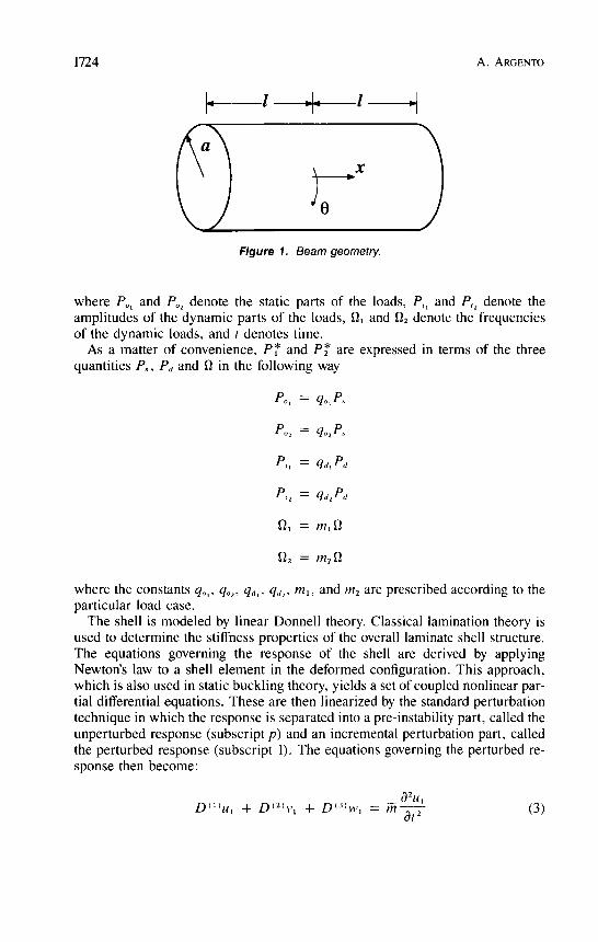
The shell is taken to have length 2l, radius a and is comprised of an arbitrarynumber of orthotropic layers. Displacement components of the shell’s middle sur-face in the axial, circumferential, and radial directions are denoted by u, v, and
w, respectively (see Figure 1). The shell is loaded by harmonic axial and torsionalloads (per unit length), respectively given by
1724
Figure 1. Beam geometry.
where POt and P02 denote the static parts of the loads, P,, and P,, denote theamplitudes of the dynamic parts of the loads, Qi and O2 denote the frequenciesof the dynamic loads, and t denotes time.As a matter of convenience, P* and P2* are expressed in terms of the three
quantities P~, Pd and Q in the following way
where the constants q~, , q02’ qd,, qd2, mi, and m2 are prescribed according to theparticular load case.The shell is modeled by linear Donnell theory. Classical lamination theory is
used to determine the stiffness properties of the overall laminate shell structure.The equations governing the response of the shell are derived by applyingNewton’s law to a shell element in the deformed configuration. This approach,which is also used in static buckling theory, yields a set of coupled nonlinear par-tial differential equations. These are then linearized by the standard perturbationtechnique in which the response is separated into a pre-instability part, called theunperturbed response (subscript p) and an incremental perturbation part, calledthe perturbed response (subscript 1). The equations governing the perturbed re-sponse then become:
1725
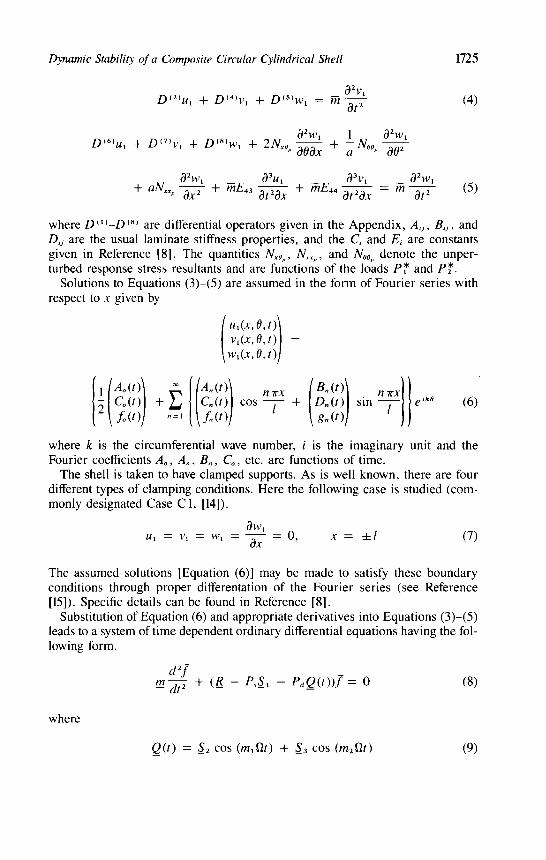
where D(l)-D(8) are differential operators given in the Appendix, A,, , B,, , andD,~ are the usual laminate stiffness properties, and the C, and E, are constantsgiven in Reference [8]. The quantities Nxop’ Nxxp’ and Noop denote the unper-turbed response stress resultants and are functions of the loads P* and P2*-
Solutions to Equations (3)-(5) are assumed in the form of Fourier series withrespect to x given by
where k is the circumferential wave number, i is the imaginary unit and theFourier coefficients Ao , An’ Bn , Co , etc. are functions of time.The shell is taken to have clamped supports. As is well known, there are four
different types of clamping conditions. Here the following case is studied (com-monly designated Case C 1, [14]).
The assumed solutions [Equation (6)] may be made to satisfy these boundaryconditions through proper differentation of the Fourier series (see Reference[15]). Specific details can be found in Reference [8].
Substitution of Equation (6) and appropriate derivatives into Equations (3)-(5)leads to a system of time dependent ordinary differential equations having the fol-lowing form.
where
1726
The quantities m, R, S,, ~2, and S, are constant matrices containing materialand geometric properties, and f is the vector of unknowns. Note that equationsreflecting the boundary conditions are also contained in Equations (8), see Refer-ence [8].For the case in which m1 and m2 are integers, the frequencies S21 and O2 are
commensurate and so then the function _Q(t) is periodic. The Equations (8) arethen a system of Hill equations. If m, = m2, _Q(t) is harmonic and Equations (8)then form a system of Mathieu equations, which is a special case of Hill equa-tions.
3. STABILITY
In this section, methods for determining the shell’s dynamic stability will be re-viewed.
In the case m, = m2 = 1, Q(t) is given by
The Equations (8) are then a system of Mathieu equations. For each circumferen-tial wave number, k, the principal regions of parametric resonance emanate inload-frequency space from the values 0 = 2~,//, where w, denote the naturalfrequencies for the particular k value and j is a positive nonzero integer. The re-gions associated with j = 1 are termed the first order regions and are ordinarilythe most significant of the principal regions. In addition, sum and differencecombination resonances may occur. These emanate from the values So =
(W, + Wl)lj and S2 = (W, - w,)/j, respectively.The principal regions of parametric resonance are most readily extracted from
the system (8) (for m, = m2) by methods set forth in the text by Bolotin [16].Specifically, the bounding branches of the instability regions are given by
In addition, the natural frequencies of the statically loaded shell, are given by
Here, the calculations (11) and (12) are made by conversion to the respectiveeigenvalue problems. Routines in the Eispack software library are used to per-form the eigenvalue calculations.The calculation (11) gives the principal regions of parametric resonance and
only applies for m, = m2. In general, stability diagrams containing all possibleregions of instability are determined using the monodromy matrix technique (see,for example, Reference [17]). To use this method, it is first assumed that m, and
1727
m2 are integers so that the function Q(t) in Equation (9) is periodic. The n x nsystem (8) is then cast as the N x N (N = 2n) first order equations:
where Z is a vector containing f and dlldt, and A_(t) is an N X N periodicmatrix having period T.
Stability of the system (13) is determined by the eigenvalues of the so-calledmonodromy matrix, M. This matrix may be obtained from the fundamentalmatrix of the system (13), ~, in the following way. Suppose that the i th columnof ~(t) is generated by the special initial conditions
for each column i = 1,2,...,N. Then, it can be shown that M and ~ arerelated by
According to Floquet’s theorem, the system (13) is then stable so long as theeigenvalues of M have magnitude less than or equal to 1.The method is quite numerically intensive since the N X N system (13) must
be numerically integrated N times over interval T. Here a single pass scheme isadopted [18,19] which results in reduced, although still high, computation time.
4. NUMERICAL RESULTS
Numerical results describing the stability of boron epoxy shells having fiber re-inforced layers are presented in this section. The properties of the material areQ = 2048 kg/m3, E, /Et = 11.11, G,,IE, = .24, vi, = .28, where Q denotesdensity, E denotes Young’s modulus, G denotes shear modulus, v denotesPoisson’s ratio, and subscripts l and t denote the directions parallel and transverseto the fiber directions, respectively.
Figures 2-6 are for a shell consisting of three equal thickness layers and fiberorientations -0/0/0. The shell’s geometry is 211a = 4 and a/h = 400 where his the total thickness of the shell.To ensure that the shell is statically stable, the applied dynamic loads, P * and
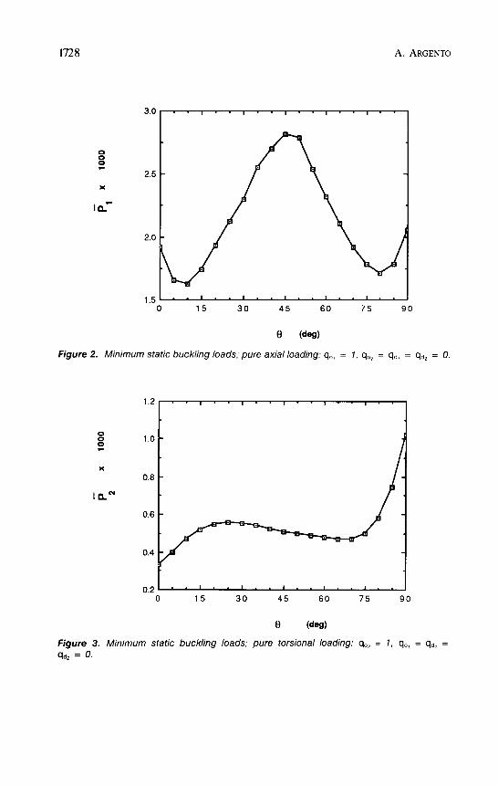
P2*, are chosen as fractions of the minimum static buckling loads. The normal-ized static buckling loads as a function of 0 are given in Figures 2-4 for pure axialloading, pure torsional loading, and combined loading, respectively. In Figures2 and 3, the minimum critical buckling loads are normalized as
1728
Figure 2. Minimum static buckling loads, pure axial loading- qo, = 1, q02 = qd, = qd2 = 0.
Figure 3. Minimum static buckling loads; pure torsional loading: q02 = 1, qo, = qd, =qd2 = 0.
1729
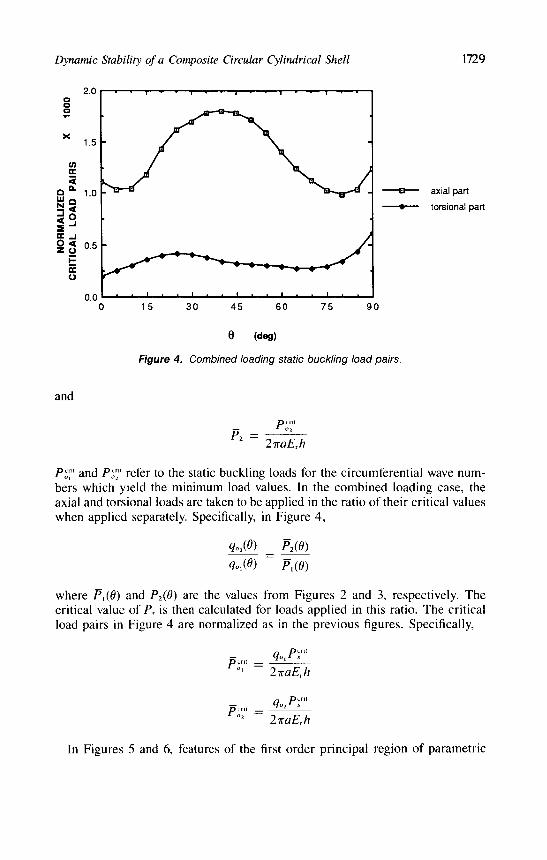
Figure 4. Combined loading static buckling load pairs
and
Po;‘ and Po2‘ refer to the static buckling loads for the circumferential wave num-bers which yield the minimum load values. In the combined loading case, theaxial and torsional loads are taken to be applied in the ratio of their critical valueswhen applied separately. Specifically, in Figure 4,
where Pi(0) and PZ(9) are the values from Figures 2 and 3, respectively. Thecritical value of P, is then calculated for loads applied in this ratio. The criticalload pairs in Figure 4 are normalized as in the previous figures. Specifically,
In Figures 5 and 6, features of the first order principal region of parametric
1730
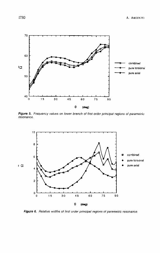
Figure 5. Frequency values on lower branch of first order principal regions of parametricresonance
Figure 6. Relative widths of first order principal regions of parametric resonance
1731
resonance are presented as a function of 0 for the common frequency case,m1 = m2 = l. For the three load cases, Figure 5 gives the normalized lowerbranch parametric resonance frequency corresponding to w, and Figure 6 givesthe corresponding normalized width of the region. The calculations are made byuse of Equation (11). For each load case the shell is taken to be subjected to staticand dynamic load magnitudes equal to .3 times the critical values given in
Figures 2-4. Thus, the shell is subjected to constant static loading and superim-posed harmonic loading. The frequency values in Figure 5 are non-dimension-alized as in [6]:
In Figure 6, S2 denotes the normalized relative widths of the instability regions.Denoting 0’ as the lower branch value and S2&dquo; as the corresponding upper branchvalue, So is defined as:
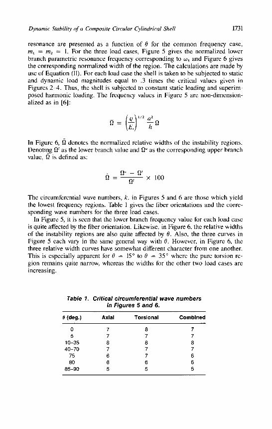
The circumferential wave numbers, k, in Figures 5 and 6 are those which yieldthe lowest frequency regions. Table 1 gives the fiber orientations and the corre-sponding wave numbers for the three load cases.
In Figure 5, it is seen that the lower branch frequency value for each load caseis quite affected by the fiber orientation. Likewise, in Figure 6, the relative widthsof the instability regions are also quite affected by 0. Also, the three curves inFigure 5 each vary in the same general way with 0. However, in Figure 6, thethree relative width curves have somewhat different character from one another.This is especially apparent for 0 = 15 ° to 9 = 35 where the pure torsion re-gion remains quite narrow, whereas the widths for the other two load cases areincreasing.
Table 1. Critical circumferential wave numbersin Figures 5 and 6.

1732
It should also be observed that although 0 > 60 is a good choice of orientationif one wishes the instability frequencies to be relatively high, the widths of thepure torsion and combined load regions achieve their largest values in this range.Also, the pure axial buckling loads are relatively low for 0 > 60. In general,overall analysis of the shell would be based on a number of factors including theexpected forcing frequency range, the expected load magnitudes and whether tor-sion, axial and/or combined loading is expected.
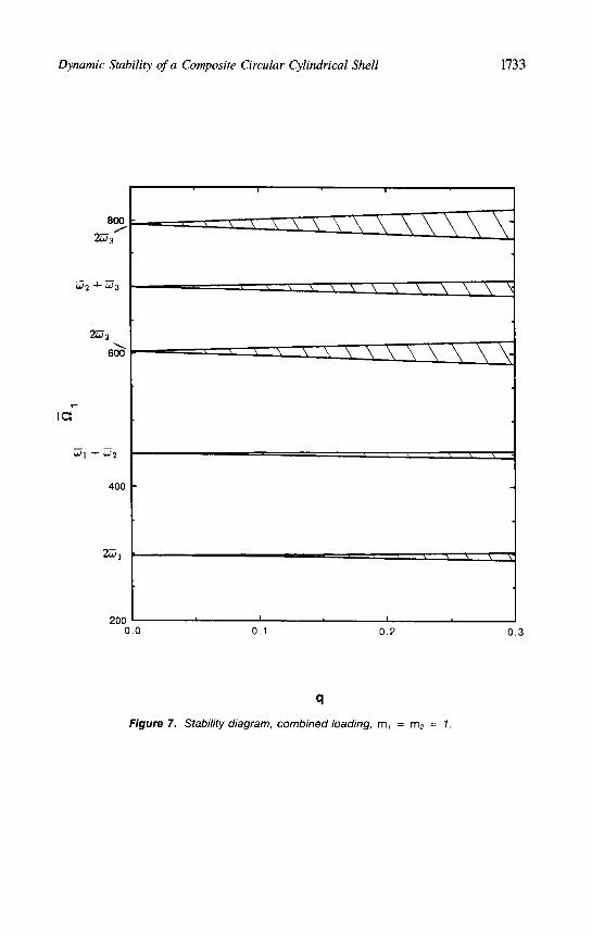
In Figures 7-10, stability diagrams are presented for a 90/0/90 shell having211a = .5 and alh = 333.3. The case of combined axial and torsional dynamicloading is studied. (The static parts of the loads are zero.). For this shell, the nor-malized minimum static buckling load pairs (combined load case) have been cal-culated to be Po;&dquo; = 1.3356 x 10⁻³, P~’ = .9616 X 10-3 when the axial alltorsional loads are applied in the ratio of their critical values when appliedseparately. In this case the ratio is given by qoB = 1, q02 = .72. The quantity qin the figures defines the applied dynamic load magnitude and is given by theratio P,,/P~&dquo; or P~/P~’. The minimum natural frequency was found usingEquation (12) to occur at k = 9. The first three normalized natural frequenciesfor k = 9 are WI = 147.9, w2 = 301.6 and W3 = 396.9. The instability of theshell, for k = 9, in the frequency range covering approximately 6 times its lowestnatural frequency is studied in the figures for the following frequency cases:MI = m2 = I; MI = 1, m2 = 2; m, = 2, M2 = 3; m, = 3, m2 = 2. Theresults in these figures were generated using the monodromy matrix techniquedescribed in the previous section. Load-frequency space was swept using a fre-quency iteration value of OSl = .45. More exact location of the instability re-gions was determined by refinement in the vicinity of the branches. Very narrowinstability regions having widths less than about .45 are not shown since dampingin the system would most likely prevent them from being physically realized. Theprincipal regions of parametric resonance can also be determined by Equation(11) for the m1 = m2 = 1 case and so was used as a check. It was found that
Equation (11) gave principal regions nearly identical to those shown in Figure 7.In all four figures it can be seen that only principal and sum combination reso-nances occur for this shell; difference combination resonances did not occur.Also, only sum combination resonances corresponding to odd-even frequencymode pairs occurred. In all cases, the instability regions were bounded by almostexactly straight lines.
In Figure 7 the common frequency case is studied. There it is seen that thewidest regions are those of principal parametric resonance corresponding to thesecond and third natural frequencies. The first (lowest frequency) combinationresonance is very narrow but the second combination resonance is about twice aswide as the lowest principal region. The normalized frequency range from 600to 800 is more dangerous from the standpoint of parametric resonance than thelower frequency range.
In Figure 8, a case in which the torsional loading is applied at twice the fre-quency of the axial loading is given. The left vertical scale gives the frequencyof the axial loading, and the right vertical scale gives the frequency of the tor-sional loading. It is seen that principal parametric resonance occurs when the
1733
Figure 7. Stability diagram, combined loadmg, m, = m2 = 1

1734
Figure 8. Stability diagram, combined loading, m, = 1, m2 = 2.
1735
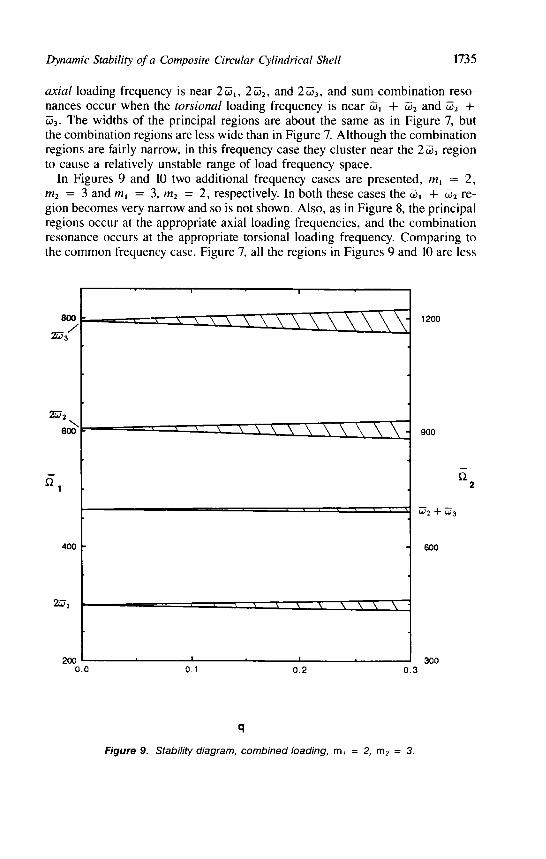
axial loading frequency is near 2-W,, 2 (ð2, and 2 W3, and sum combination reso-nances occur when the torsional loading frequency is near &1 + (ð2 andw2 +(ð3’ The widths of the principal regions are about the same as in Figure 7, butthe combination regions are less wide than in Figure 7. Although the combinationregions are fairly narrow, in this frequency case they cluster near the 2-W, regionto cause a relatively unstable range of load frequency space.
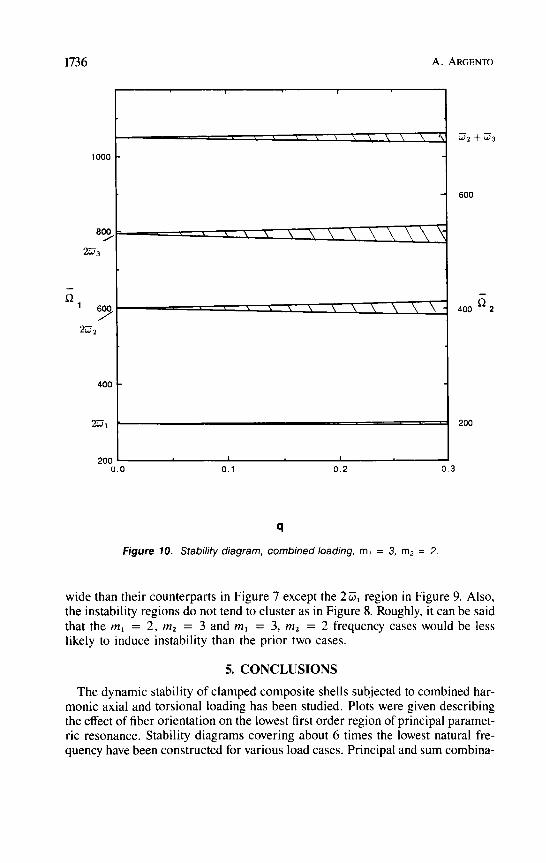
In Figures 9 and 10 two additional frequency cases are presented, m, = 2,m2 = 3 and mi = 3, m2 = 2, respectively. In both these cases the 0)1 + w2 re-gion becomes very narrow and so is not shown. Also, as in Figure 8, the principalregions occur at the appropriate axial loading frequencies, and the combinationresonance occurs at the appropriate torsional loading frequency. Comparing tothe common frequency case, Figure 7, all the regions in Figures 9 and 10 are less
Figure 9. Stabihty diagram, combined loadmg, m, = 2, m2 = 3.
1736
Figure 10. Stability diagram, combmed loading, m¡ = 3, m2 = 2
wide than their counterparts in Figure 7 except the 2-W, region in Figure 9. Also,the instability regions do not tend to cluster as in Figure 8. Roughly, it can be saidthat the m, = 2, M2 = 3 and m, = 3, M2 = 2 frequency cases would be lesslikely to induce instability than the prior two cases.
5. CONCLUSIONS
The dynamic stability of clamped composite shells subjected to combined har-monic axial and torsional loading has been studied. Plots were given describingthe effect of fiber orientation on the lowest first order region of principal paramet-ric resonance. Stability diagrams covering about 6 times the lowest natural fre-quency have been constructed for various load cases. Principal and sum combina-
1737
tion resonances have been found to occur for the cases studied here. It has beenshown that the widths of the instability regions and the relative location of the re-gions in load frequency space is affected by the ratio of the frequencies of the ap-plied loads.
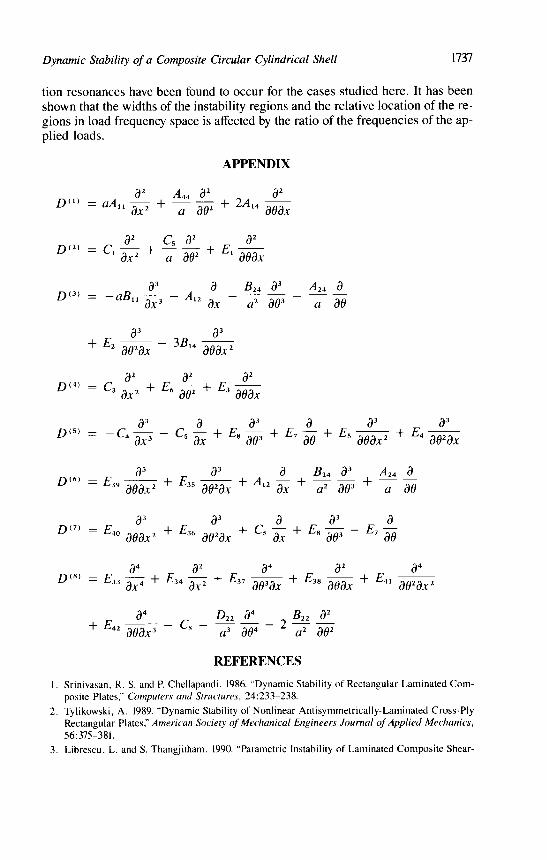
APPENDIX
REFERENCES
1 Srinivasan, R S and P Chellapandi 1986 "Dynamic Stability of Rectangular Laminated Com-posite Plates," Computers and Structures, 24 233-238
2 Tylikowski, A 1989 "Dynamic Stability of Nonlinear Antisymmetrically-Laminated Cross-PlyRectangular Plates," American Society of Mechanical Engineers Journal of Applied Mechanics,56 375-381
3 Librescu, L and S Thangjitham 1990 "Parametric Instability of Laminated Composite Shear-
1738
Deformable Flat Panels Subjected to In-Plane Edge Loads," Int. J Non-Linear Mechanics,25:263-273
4. Bert, C. W. and V. Birman. 1987. "Dynamic Instability of Shear Deformable AntisymmetricAngle-Ply Plates," Int. J. Solids Structures, 23:1053-1061
5. Moorthy, J., J. N. Reddy and R. H. Plaut. 1990. "Parametric Instability of Laminated CompositePlates with Transverse Shear Deformation," Int. J. Solids Structures, 26.801-811.
6. Bert, C. W. and V. Birman. 1988. "Parametric Instability of Thick Orthotropic, Circular Cylin-drical Shells," Acta Mechanica, 71:61-76.
7. Argento, A. and R. A. Scott. 1989. "Parametric Resonance of Arbitrarily Layered Fiber Rein-forced Composite Circular Cylindrical Shells," Proceedings of the 4th Technical Conference ofthe American Society of Composites, pp 649-656.
8. Argento, A. and R. A Scott. 1993. "Dynamic Instability of Layered Anisotropic Circular Cylin-drical Shells, Part I: Theoretical Development," Journal of Sound and Vibration, 162:311-322.
9. Argento, A. and R. A Scott 1993. "Dynamic Instability of Layered Anisotropic Circular Cylin-drical Shells, Part 2: Numerical Results," Journal of Sound and Vibration, 162.323-332
10. Goroshko, O. A and V V. Emel’yanenko. 1975. "Dynamic Stability of Layered AnisotropicShells," Soviet Applied Mechanics. UDC539.3:534.1, pp. 720-725.
11. Stuart, R. J., S. Dharmarajan and L. E. Penzes. 1980. "Dynamic Stability of Fibrous CompositeCylinders," in Fibrous Composites in Structural Design. New York: Plenum Press, pp. 329-340
12. Aida, T 1989 "Dynamic Stability of Thin-Walled Structural Members under Periodic AxialTorque," ASCE Journal of Engineering Mechanics, 115:71-88
13 Plaut, R. H , J J Gentry and D T Mook. 1990. "Non-Linear Structural Vibrations under Com-bined Multi-Frequency Parametric and External Excitations," Journal of Sound and Vibration,140.381-390.
14. Brush, D. O and B. O Almroth 1975. Buckling of Bars, Plates, and Shells. New York McGraw-Hill.
15. Whitney, J M and C. T. Sun 1975. "Buckling of Composite Cylindrical Characterization Speci-mens," J Composite Materials, 9 138-148
16. Bolotin, V. V. 1964 The Dynamic Stability of Elastic Systems San Francisco: Holden-Day17. Meirovitch, L. 1970. Methods of Analytical Dynamics. New York McGraw-Hill.
18. von Kerczek, C and S. H. Davis. 1975. "Calculation of Transition Matrices," AIAA Journal,13:1400-1403.
19 Gaonkar, G. H., D S. Simha Prasad and D Sastry 1981. "On Computing Floquet TransitionMatrices of Rotorcraft," Journal of the American Helicopter Society, 26 56-61.