instability of imperfect composite cylindrical · pdf fileinstability of imperfect composite...
TRANSCRIPT
Tafreshi, A. & Bailey, Colin G., Sep. 2007 In : Composite Structures. 80, 1, p. 49-64 16 p.
1
INSTABILITY OF IMPERFECT COMPOSITE CYLINDRICAL SHELLS UNDER
COMBINED LOADING
Azam Tafreshi* and Colin G Bailey
School of Mechanical, Aerospace and Civil Engineering, MACE
The University of Manchester, P.O.Box 88, Sackville Street
Manchester M60 1QD, United Kingdom
*Corresponding author ([email protected])
ABSTRACT
A numerical study using the non-linear finite element analysis has been carried out to
investigate the response of composite cylindrical shells subject to combined loading. The
interaction buckling curves of perfect composite cylinders subject to different combinations
of axial compression, torsion, bending and lateral pressure are obtained. The postbuckling
analysis of composite cylinders with geometric imperfections of eigenmode-shape is
carried out to study the effect of imperfection amplitude on the critical buckling load. The
initial buckling load of composite shells is substantially reduced by the existence of
imperfections. Here it is shown that the effects of imperfections are more apparent when
the composite cylindrical shells are subject to combined loadings. The results show that
the buckling and non-linear response of geometrically imperfect shell structures subjected
to complex loading conditions may not be characterized correctly by an elastic linear
bifurcation buckling analysis.
Keywords: Composites, finite element method, buckling and postbuckling, laminated
cylindrical shells, external pressure, axial compression, torsion, bending, combined loading
NOMENCLATURE
E11, E22, G12, 12 material constants
L, r, t mength, radius and thickness of the overall cylindrical shell,
respectively
M bending moment

Tafreshi, A. & Bailey, Colin G., Sep. 2007 In : Composite Structures. 80, 1, p. 49-64 16 p.
2
Mc critical bending moment of a perfect cylinder under bending
alone
P pressure
Pc critical buckling pressure of a perfect cylinder under external
pressure alone
R compressive axial load
Rc critical buckling load of a perfect cylinder under axial
compression alone
T torque
Tc critical buckling load of a perfect cylinder under torsion
alone
U (or ux),v (or uy),w (or uz) axial, circumferential and radial displacements, respectively
x, y, z axial, circumferential and radial coordinates, respectively
x, y,z rotation about the y, x, and z axes, respectively
1. INTRODUCTION
Laminated composite materials are increasingly being used in the aerospace, civil, marine,
automobile, and other engineering industries. This is due to their high strength and
stiffness-to-weight ratios. The phenomenon of progressive failure in laminated composite
structures is yet to be understood, and as a result, reliable strategies for designing optimal
composite structures for desired life and strength are in demand [1-3].
In previous studies carried out by the first author [4-6], the effects of delamination on the
buckling and postbuckling behaviour of composite cylindrical shells subject to axial
compression and lateral pressure were investigated. The loads were either applied
individually [1-2] or were combined [3]. Despite the relatively widespread attention given
to the problem of delamination in laminated composites, there is hardly any information
available on the effect of delamination in a composite cylindrical shell under combined
loading. However, this study could not be performed without deep insight into the
behaviour of a typical intact composite cylinder, with or without geometric imperfections,
subject to complex loading conditions.
Tafreshi, A. & Bailey, Colin G., Sep. 2007 In : Composite Structures. 80, 1, p. 49-64 16 p.
3
Thin-walled circular cylindrical shells are very often loaded in a way that the three
buckling membrane forces; axial compression, circumferential compression and shear, are
not applied individually but in combination. Therefore, a designer not only has to consider
the buckling characteristics of a cylindrical shell under fundamental stress states, but also
the interactive buckling.
There is a reasonable amount of work on the instability response of laminated cylindrical
shells under axial compression, pressure, external pressure, bending and torsion [7-17]
applied individually. Ref. [18] consists of a comprehensive study on the stability of
cylindrical steel shells under combined loading. Thus, very limited information on the
instability response of composite shells under combined loading is available [19-30] and
most of it does not consider the postbuckling response which, if considered, will result in
significant cost savings. Most of the published data deals with the buckling response of
compression-loaded composite shells. The early work of Manuel Stein [31] on the effects
of geometrical imperfections on the stability of isotropic plates and shells must also be
cited.
The traditional method for designing thin-walled shell structures to resist buckling failure is
to predict the buckling load of the shell using the analytical or numerical methods. This
buckling load will then be reduced with an empirical reduction factor accounting for the
imperfections of the structure. The other most realistic, but costly, approach is to analyse
the actual imperfect shell structure as generated from measurements after fabrication and
erection[11,12, 18, 28, 29, 32-34]. This imperfection data can be directly implemented into
Finite Element (FE) models and then analysed. The other most recent and feasible
approach is to introduce a simple equivalent geometric imperfection which properly
simulates the physical characteristics of the shell structure subject to buckling. This
equivalent geometric imperfection can be either of the eigenmode shape [23,26] or can be
defined analytically [16, 21, 27]. However, the amplitude of the imperfection shape has a
great influence on the non-linear response of the shell structure. Therefore, imperfection
Tafreshi, A. & Bailey, Colin G., Sep. 2007 In : Composite Structures. 80, 1, p. 49-64 16 p.
4
amplitude usually has to be calibrated against existing experimental databases for known
shell buckling cases.
This paper deals with the buckling and postbuckling analysis of perfect and imperfect
composite cylindrical shells subject to combined loading. The loading cases considered are
axial compression, lateral pressure, torsion and bending, either applied individually and in
combination. At most, the combination of three different types of loadings are considered.
First, the interactive buckling curves of a typical cylindrical shell subject to different
combinations of the preceding mentioned load cases are obtained. Whenever possible, the
results are compared with corresponding numerical or analytical studies presented by other
authors. The postbuckling response of composite cylinders with geometric imperfections
of eigenmode-shape is carried out to study the effect of imperfection amplitude on the
critical buckling load, when the loads are applied either individually or in combination.
The analysis has been carried out using ABAQUS 6.4 [35], which is available on the
mainframe computer, Bezier, at the Manchester Computing Centre.
2. BUCKLING AND POSTBUCKLING ANALYSIS USING THE FINITE
ELEMENT METHOD
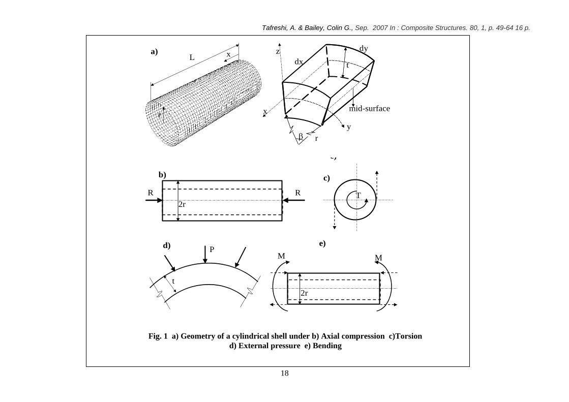
Fig. 1 shows a typical cylindrical shell subjected to simultaneous loading of axial
compression, R, torque, T, bending moment, M, and lateral pressure, P. Throughout this
study the external pressure is assumed to be positive and the internal pressure is assumed
to be negative. Fig. 1a shows a differential element of a perfect cylindrical shell segment
with the coordinate axes. The axial coordinate is x, the circumferential coordinate is y,
and the thickness coordinate normal to the shell surface is z. The circumferential
coordinate can be replaced by y=r. The axial load(R) is a uniform compressive force
applied at the ends of the shell. The internal or external pressure is also uniformly
distributed on the inner or outer surface of the shell, respectively. To apply pure bending
or torsional moments, using the coupling technique in ABAQUS, all the nodes on each
end cross-section were kept on the same respective plane. Then two concentrated loads
in opposite directions were applied in the x direction or z direction to simulate bending or
Tafreshi, A. & Bailey, Colin G., Sep. 2007 In : Composite Structures. 80, 1, p. 49-64 16 p.
5
torsion, respectively. See Figs.1c and 1e. This method of loading will ensure that the
shell is subject to pure bending or torsion and the end cross-sections remain on the same
planes after deformation, which properly models the actual experimental conditions.
Also, the two concentrated loads applied would not create a very high local stress
concentration.
For the finite element analysis of a typical cylindrical shell, a single layer of shell elements,
designated S8R in ABAQUS, can be employed and the corresponding buckling and
postbuckling analysis can be performed. S8R is an eight noded shear deformable shell
element with reduced integration, which allows large rotations and small strains. The
number of shell elements which were used for the modelling of the cylindrical shells
throughout this study was 2500.
The first stage in the simulation is a linear eigenvalue buckling analysis. In simple cases,
linear eigenvalue analysis may be sufficient for design evaluation; but geometrically
nonlinear static problems sometimes involve buckling or collapse behaviour, where the
load-displacement response shows a negative stiffness and the structure must release
strain energy to remain in equilibrium. Several methods [35-39] are available for
modelling such behaviour. One method is to treat the buckling response dynamically,
therefore, modelling the response, with inertia effects included, as the structure snaps.
This approach can be carried out by restarting the terminated static procedure and
switching to a dynamic procedure when the static solution becomes unstable. Another
approach for finding static equilibrium states, during the unstable phase of the response,
is the modified RIKS method available in ABAQUS. The Riks method is based on
moving with fixed increments along the static equilibrium path in a space defined by the
displacements and a proportional loading parameter. This method is used for cases where
the loading is proportional, therefore, the load magnitudes are governed by a single scalar
parameter. Arc length methods such as the Riks method are global load-control methods
that are suitable for global buckling and postbuckling analyses; they do not function well
when buckling is localized. Another method is to use dashpots to stabilize the structure
during a static analysis. ABAQUS offers an automated version of this stabilization
Tafreshi, A. & Bailey, Colin G., Sep. 2007 In : Composite Structures. 80, 1, p. 49-64 16 p.
6
approach for the static analysis procedures. This method has been successfully used in the
earlier studies of the first author [4-5] for the analysis of delaminated composite shells
where buckling is mostly localized.
In the current study the Riks method has been employed. It should be noted that the
initial small deflection that is necessary to make the structure buckle was established by
imposing an imperfection based on the first buckling mode. The imperfection amplitude
varied from 0.01t to t, where t is the thickness of the shell.
Fig. 2 shows the first buckling mode of a graphite-epoxy cylindrical shell subject to axial
compression, torsion, bending and external pressure, applied individually. The
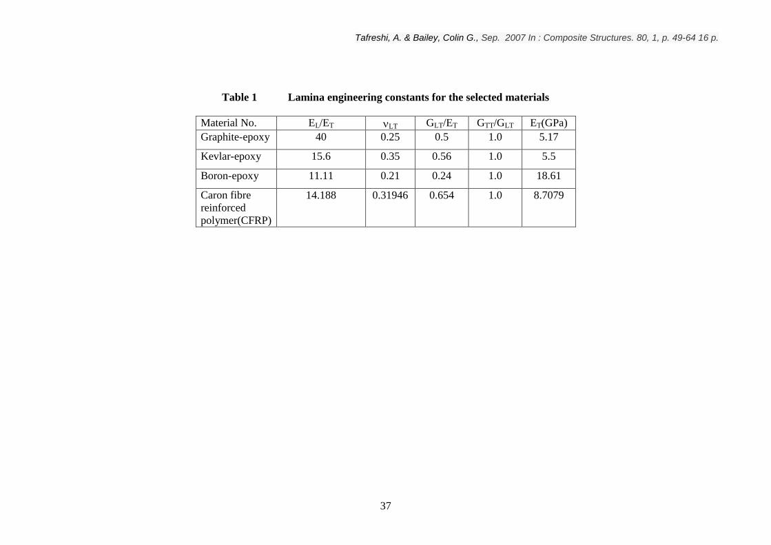
dimensions of the clamped shell are L/r=5 and r/t=30. For the lamina engineering
constants of the selected materials throughout this study refer to Table 1.
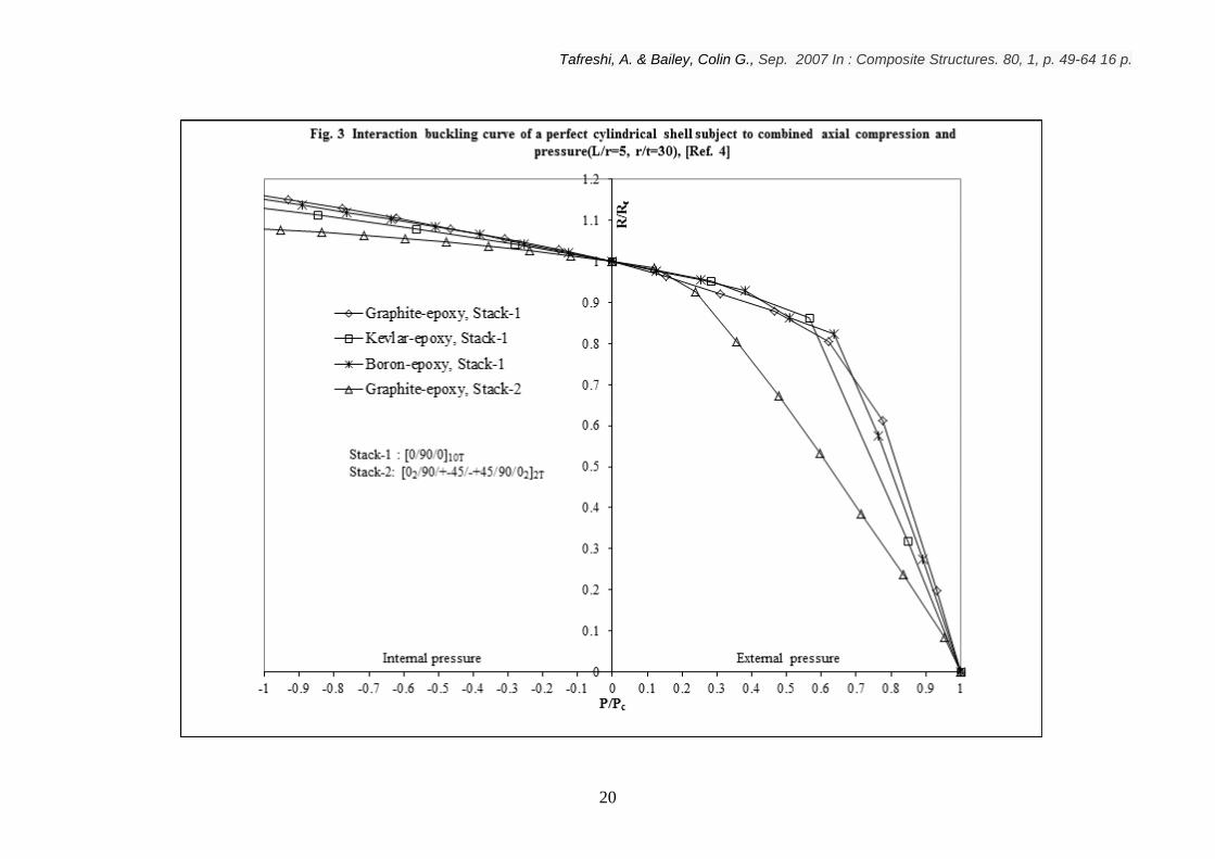
In a recent study [4], the interaction buckling curve of the preceding laminated cylindrical
shell with clamped ends subjected to simultaneous axial compression and external pressure,
was obtained. The loading case of axial compression combined with internal pressure was
also considered. In order to examine the effect of the stacking sequence on the buckling of
delaminated cylinders, two different stacking sequences T100/90/0 ,
T222 0/90/45/45/90/0 , respectively, were chosen for the analysis. For the stacking
sequence of [0/90/0]10T, three different materials; graphite-epoxy, kevlar-epoxy and boron-
epoxy were considered. Fig. 3 shows the interaction buckling curves, relating pressure
(P/Pc) and axial compressive load(R/Rc), through a range of values of P, from buckling
under external pressure(P=Pc) to internal pressure (P=-Pc), for the selected materials. Rc
and Pc are the critical axial compressive load and critical external pressure of a perfect
cylinder under axial compressive load alone and external pressure alone, respectively. The
results show that for the selected materials, of the stacking sequence 1, the trends of the
variation of the interaction curves are similar. Therefore, it can be concluded that the
material properties do not have a significant influence on the variation of the interaction
buckling curve. Next, the effect of the stacking sequence of the laminate on the shape of
the interaction buckling curve was investigated. Fig.3 also shows the interaction buckling
Tafreshi, A. & Bailey, Colin G., Sep. 2007 In : Composite Structures. 80, 1, p. 49-64 16 p.
7
curve for the stacking sequence of T222 0/90/45/45/90/0 with the graphite-epoxy
material properties. For the sake of brevity, and clarity of presentation, the results for the
kevlar-epoxy and boron epoxy cylinders with the aforementioned stacking sequence were
obtained but were not presented. However, they had similar trends as the interaction curve
of the graphite-epoxy. By comparing the interaction buckling curves of the graphite-epoxy
cylinder with the two different stacking sequences, it can be observed that the shape of the
interaction buckling curve is mainly influenced by the stacking sequence. The difference
between the interaction curves is less evident when the cylinder is subject to internal
pressure and more apparent when the cylinder is subject to high level of external pressure.
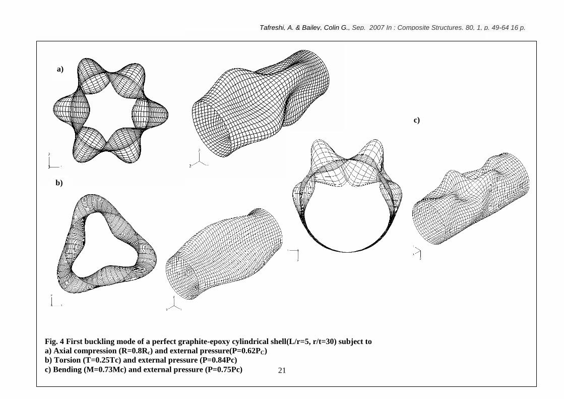
Fig. 4a shows the first buckling mode of the cylinder subject to combined axial
compression and external pressure.
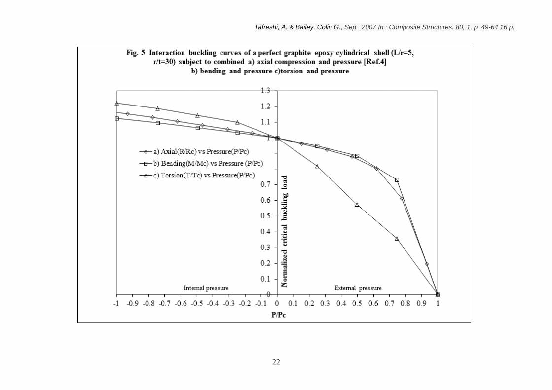
In this study the interaction buckling curves of the preceding cylinder with graphite-epoxy
material properties and stacking sequence of T100/90/0 , for bending moment(M/Mc)
against pressure (P/Pc) and torsion(T/Tc) against pressure (P/Pc), are obtained (Fig. 5). The
interaction buckling curve of the same cylinder, for axial compression (R/Rc) against
pressure (P/Pc), is also shown in Fig. 5. Mc and Tc are the critical buckling loads when the
cylinder is subject to pure bending or pure torsion, respectively. It can be observed that the
buckling curves of the bending vs pressure and axial compression vs pressure have similar
trend of variation. However, the buckling curve for the torsion shows that the external
pressure greatly reduces the critical torsional moment. Generally speaking, for the three
buckling curves, the critical buckling load increases when the cylinder is subjected to
internal pressure and the critical load has almost a linear variation with respect to the
increase of the internal pressure. Figs. 4b and 4c show the first buckling mode of the
cylinder subject to combined bending-external pressure and torsion-external pressure,
respectively.
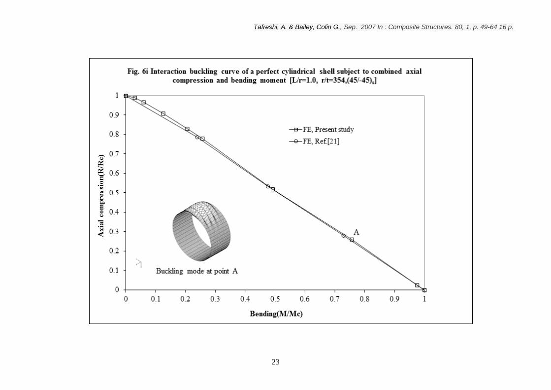
In a study by Simitses el al [21], the nonlinear analysis of imperfect metallic and laminated
cylinders under bending and axial compression, using the finite element analysis, was
carried out. In their paper they have presented interactive buckling curves, axial
compression vs bending, of a boron-epoxy cylindrical shell (L/r=1.0 and r/t=354) with the
Tafreshi, A. & Bailey, Colin G., Sep. 2007 In : Composite Structures. 80, 1, p. 49-64 16 p.
8
stacking sequence of [45/-45]s. Fig. 6-i shows the buckling curve produced by Simiteses et
al in reference [21] which has a linear variation. Fig. 6-i also shows the buckling curve,
axial compression vs bending, of the same cylinder obtained in this study. It can be
observed that the relationship between critical loads of cylinders under compression and
bending is almost linear except those of the laminated cylinder under a very high
compression load.
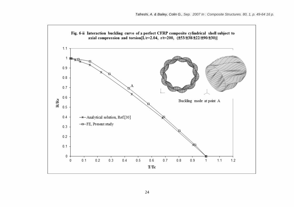
Meyer-Piening et al [30] presented the buckling loads of Carbon Fibre Reinforced
Polymer[CFRP] composite cylinders under combined axial and torsion loadings. In their
work they have compared their experimental results with the corresponding analytical
results. Here the FE results of the current study have been compared with the
corresponding analytical solution. Fig. 6-ii shows the interactive buckling curves for a
CFRP composite cylindrical shell (L/r=2.04 and r/t=200) with the stacking sequence of
[53/38/22/90/30] used by Meyer-Piening et al and also the buckling curve obtained
in this study. It can be observed that the trends of variation of both results are similar.
However, the FE results show slightly higher buckling loads than the analytical solution.
Next, the linear buckling analysis was performed on a graphite epoxy cylindrical shell
[L/r=5, r/t=30 and (0/90/0)10T] subject to axial compression, bending and external pressure.
Each analysis was performed in three different steps. For each combined loading case,
initially a live pressure load was applied to the shell, then a bending moment was applied to
the pressurized shell in the second step and in the final step the critical axial compressive
load was determined. Using ABAQUS it is also possible to apply the bending moment in
the first step and the pressure in the second step and finally determine the critical axial
compressive load.
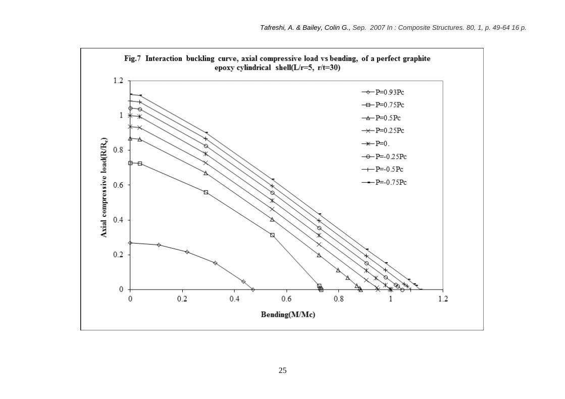
Fig. 7 shows the interaction buckling curves, axial compression(R/Rc) vs bending(M/Mc),
at different pressure levels. The pressure level varies from cP75.0 to cP93.0 . It can be
seen that the internal pressure increases the critical buckling load and onset of the buckling
mode. However, for high values of the external pressure the critical buckling load
decreases dramatically. The buckling curves for the pressure level of P<0.5Pc are almost

Tafreshi, A. & Bailey, Colin G., Sep. 2007 In : Composite Structures. 80, 1, p. 49-64 16 p.
9
linear except those of the laminated cylinder under very high compression load. The
buckling curves for the pressure levels of P>0.5Pc have a parabolic shape.
A similar set of results has also been obtained for the combined loadings of axial
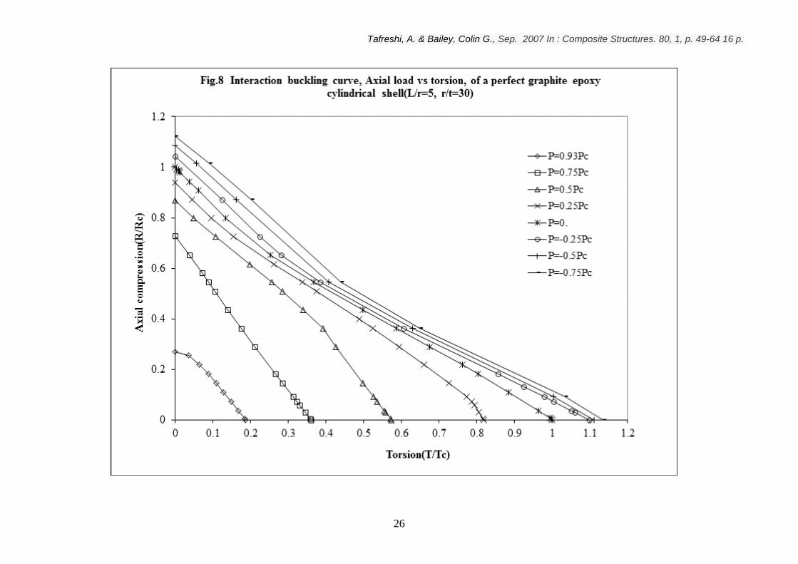
compression, torsion and lateral pressure. Fig. 8 shows the interaction buckling curves,
axial compression(R/Rc) vs torsion (T/Tc), at pressure levels varying from cP75.0 to
cP93.0 . It can be seen that the internal pressure increases the critical buckling load and
onset of the buckling mode. However, for high values of the external pressure the critical
buckling load decreases drastically. It can be observed that for the pressure level of P>0.
each buckling curve consists of two lines intersecting at T/Tc 0.4. For T/Tc >0.4 the rise
of the internal pressure slightly increases the critical axial load. This rate of increase is
relatively higher for T/Tc <0.4.
Fig. 9a shows the first buckling mode of a graphite epoxy cylinder subject to axial
compression, bending and external pressure. Fig. 9b shows the first buckling mode of the
same cylinder subject to axial compression, torsion and external pressure.
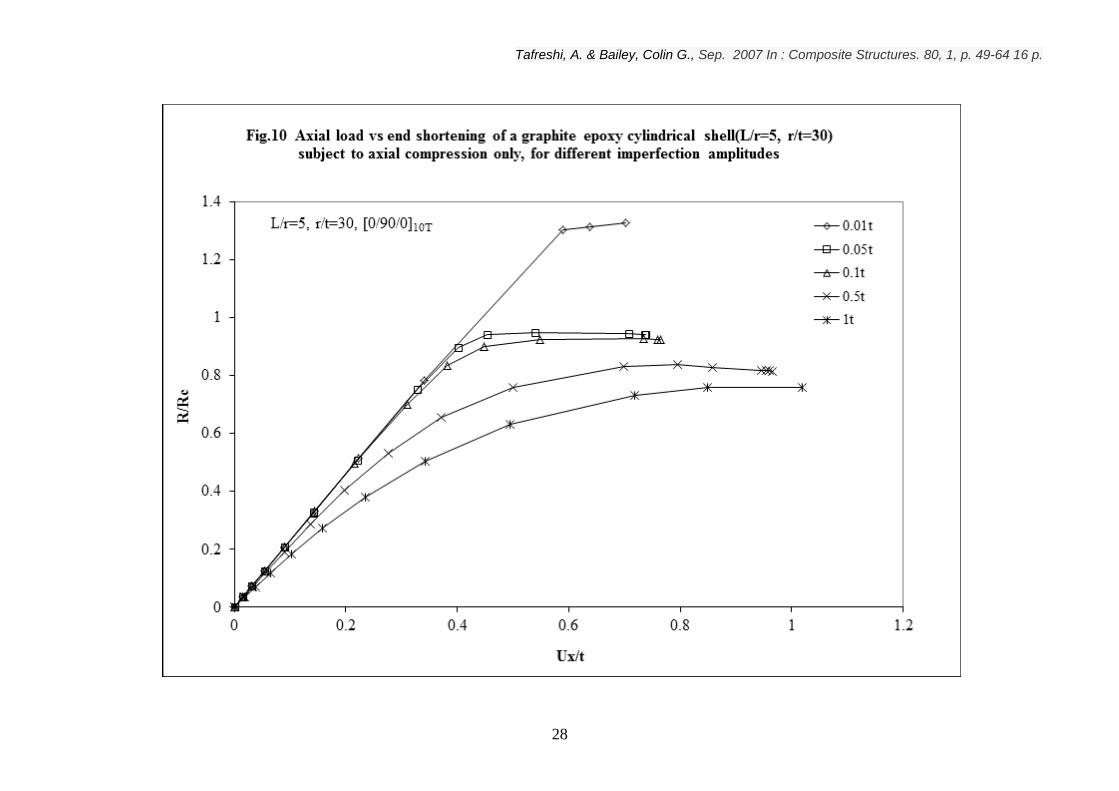
Next, the postbuckling analysis was performed. The imperfection amplitude varied from
0.01t to 1t. Fig. 10 shows the load-shortening response (R/Rc vs Ux/t) of the preceding
cylinder when it is subject to axial compression alone. The effect of geometric
imperfection is clearly evident. It can be observed that for a small imperfection amplitude,
the critical load can be significantly greater than the critical buckling load of the perfect
cylinder subject to the same loading conditions. For larger imperfection amplitudes,
initially the evolution of the displacements produced by the applied load is very smooth but
as soon as the global instability develops the displacements dramatically increase with the
increase applied axial compressive load, indicating the complete loss of load-carrying
capacity of the structure.
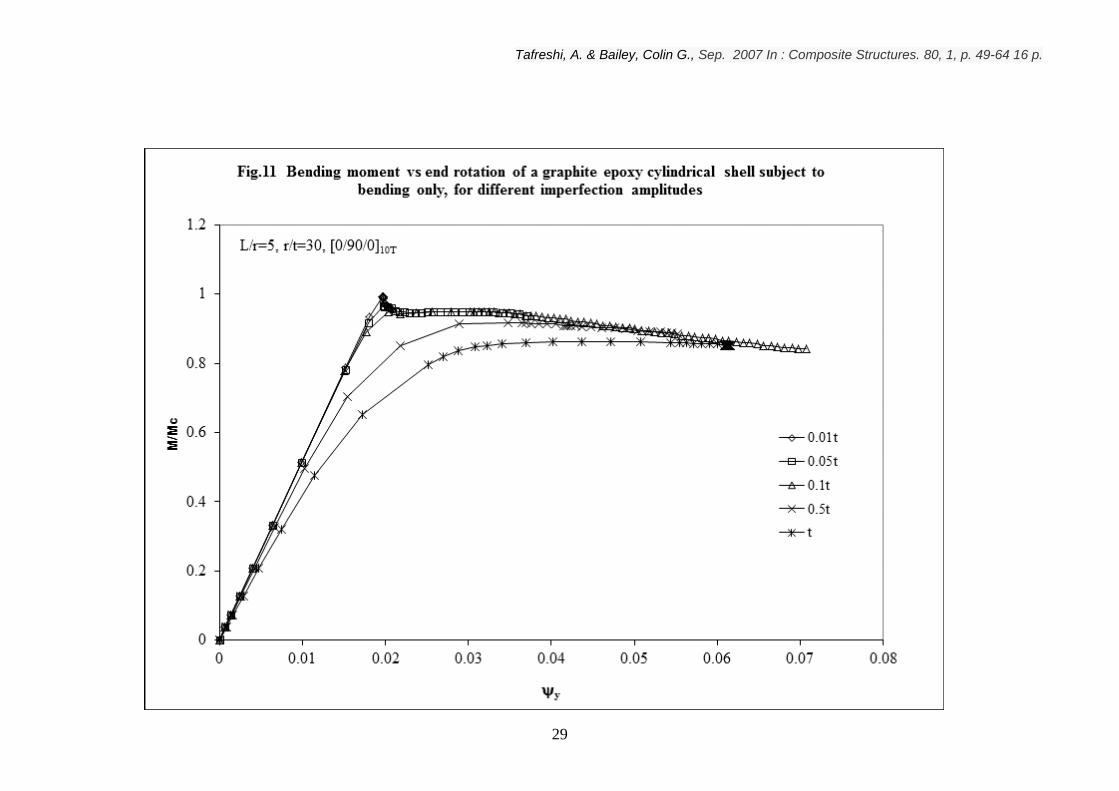
Fig. 11 shows the bending moment (M/Mc) vs end rotation(y) of the preceding cylinder
when it is subject to the bending moment alone. The results show that for a small
imperfection amplitude, the critical buckling load is almost the same as the critical
Tafreshi, A. & Bailey, Colin G., Sep. 2007 In : Composite Structures. 80, 1, p. 49-64 16 p.
10
buckling load of a perfect cylinder. Obviously for larger imperfection amplitudes the
critical buckling load drops sharply, however, in comparison with the axial loading case the
cylinder subject to bending is less imperfection sensitive.
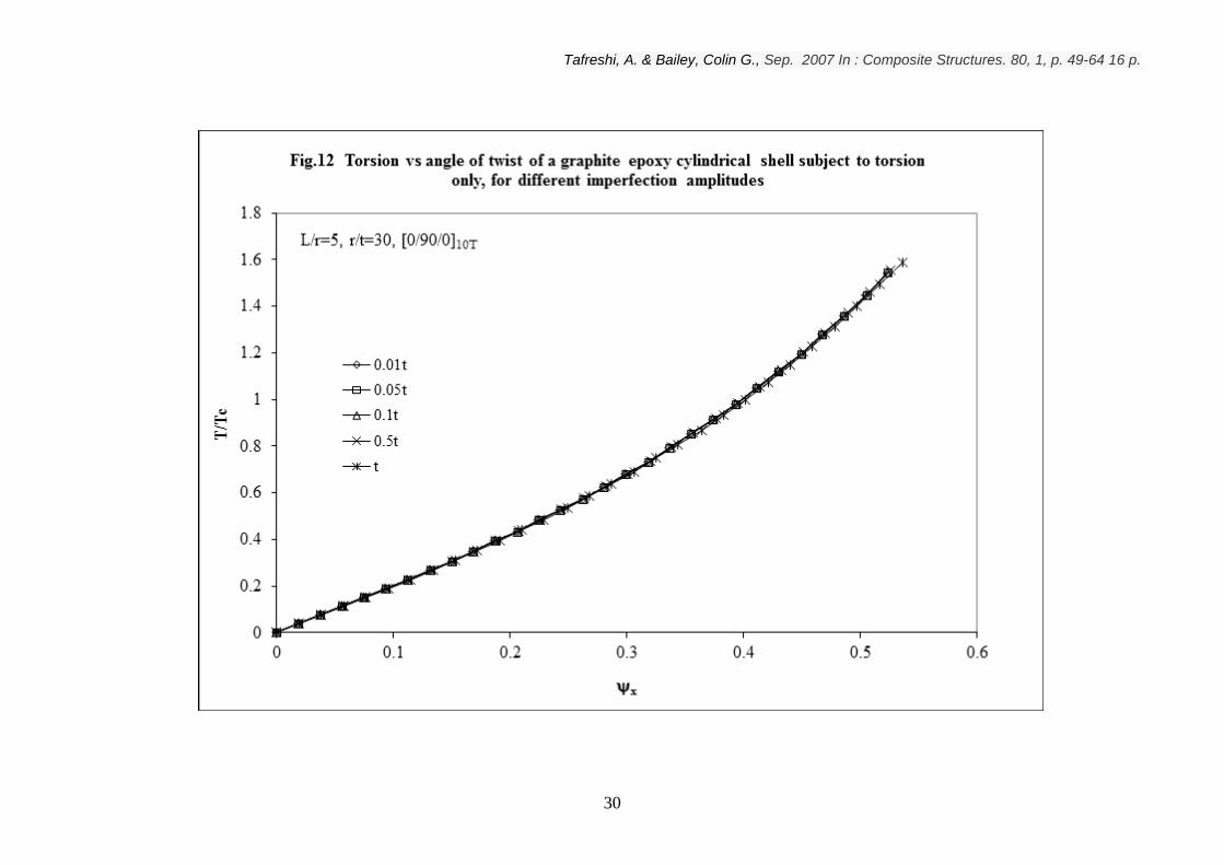
Fig. 12 shows the torsion (T/Tc) vs angle of twist (x) of the above cylinder when it is
subject to torsion alone, for different imperfection amplitudes. The results show that the
cylinder has almost the same response, irrespective of the imperfection amplitude.
Therefore, it can be said that when the cylinder is subject to torsion alone it is virtually
imperfection-insensitive. This agrees with the analytical results of Simitses el al [17] and
experimental results of Meyer-Piening et al [30].
Next, the postbuckling response of the above cylinder subject to combined axial
compression and bending moment was obtained. For each combined loading case, initially
a live bending moment was applied to the shell, then the axial compressive load was set to
increase up to 1.2 times the critical axial compressive load of a perfect cylinder, subjected
to axial compressive load alone. Figs. 13a, b and c show the load-shortening response
(R/Rc vs Ux/t) of the cylinder subject to the preloading of 0.1Mc, 0.2Mc and 0.4Mc,
respectively. A similar set of results are obtained for the cylinder subject to combined axial
compression and torsion. For each combined loading case, initially a live torsion was
applied to the shell, then the axial compressive load was set to increase up to 1.2 times the
critical axial compressive load of a perfect cylinder, subjected to axial compressive load
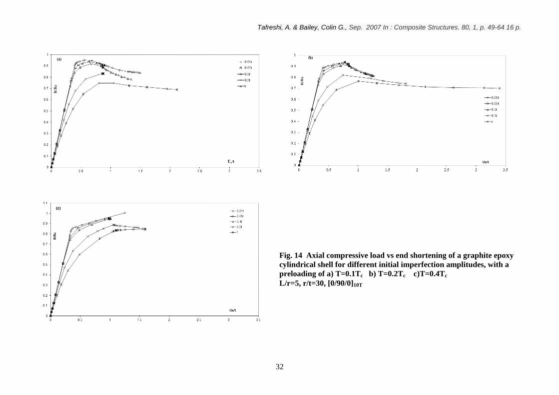
alone. Figs. 14a, b and c show the load-shortening response (R/Rc vs Ux/t) of the cylinder
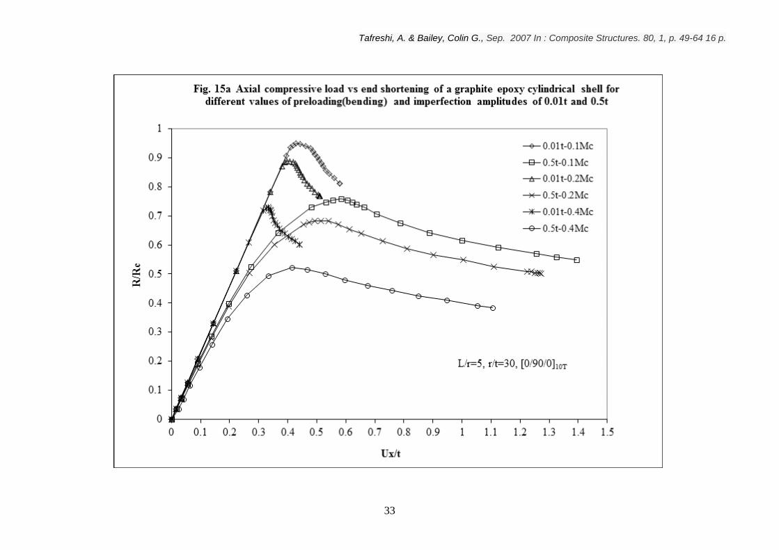
subject to the preloading of 0.1Tc, 0.2Tc and 0.4Tc, respectively. Fig. 15-a compares the
postbuckling response of the cylinder subject to combined axial compression and bending,
for the imperfection amplitudes of 0.01t and 0.5t, for the preloadings of 0.1Mc, 0.2Mc and
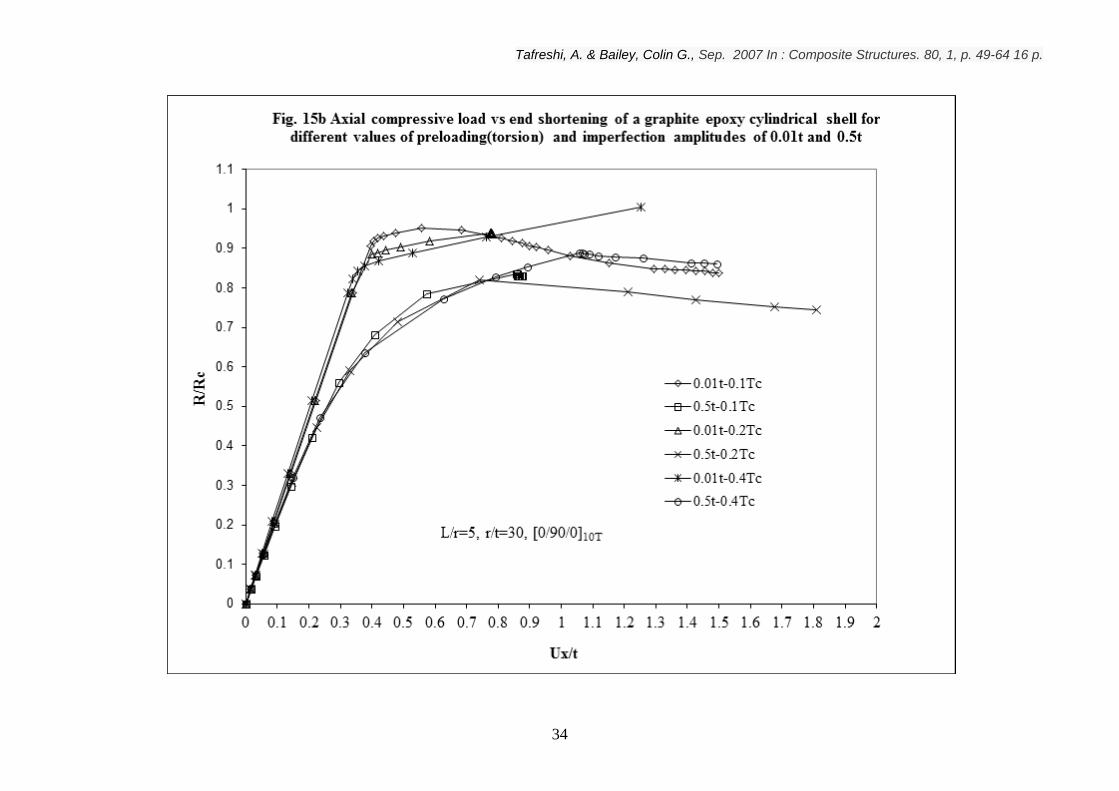
0.4Mc, respectively. Fig. 15-b compares the postbuckling response of the cylinder subject
to combined axial compression and torsion, for the imperfection amplitudes of 0.01t and
0.5t, for the preloadings of 0.1Tc, 0.2Tc and 0.4Tc, respectively. Figs. 16a and 16b show
the collapse load of the cylinder with respect to the increase of the imperfection amplitude,
for the combined axial compression-bending and axial compression-torsion cases,
Tafreshi, A. & Bailey, Colin G., Sep. 2007 In : Composite Structures. 80, 1, p. 49-64 16 p.
11
respectively. The collapse load is the maximum load which the structure can support. The
following observations have been made from this study.
The results show that for the lower values of the preloading and imperfection amplitudes of
less than 0.1t, the response of the shell is almost imperfection-insensitive. For the large
values of the preloading and large imperfection amplitudes, the prebuckling stiffness drops
drastically, the structure becomes imperfection-sensitive and the postbuckling response
becomes more stable. The stability of the postbuckling response of the cylinder subject to
combined axial compression and torsion is more apparent. It can also be observed that for
the combined axial compression and torsion, for small imperfection amplitudes, the elastic
limit of the axial compressive load is almost independent of the value of the preload. For
the case of combined axial compression and bending, the collapse load decreases with the
increase of the imperfection amplitude and the preloading value. For the case of combined
axial compression and torsion, for the same preloading value, the collapse load decreases
with the increase of the imperfection amplitude. However, for the same imperfection
amplitude the collapse load increases with the increase of the preloading value.
3. CONCLUDING REMARKS
Computational analysis using the finite element method has been carried out to study the
response of perfect and imperfect composite cylindrical shells under combined loading.
The interaction buckling curves of perfect composite shells subject to different
combinations of axial compression, bending, torsion and lateral pressure are obtained.
The postbuckling analysis of composite cylinders with geometric imperfections of eigen-
mode shape is carried out to investigate the effect of imperfection amplitude on the
critical buckling load.
The results show that a very small imperfection amplitude does not appreciably alter the
critical load of a perfect geometry under the same loading condition. For the combined
loading case, it was observed that the internal pressure increases the critical buckling load
and onset of the buckling mode. For high values of external pressure, the critical
buckling load decreases dramatically. The results show that under torsion, laminated

Tafreshi, A. & Bailey, Colin G., Sep. 2007 In : Composite Structures. 80, 1, p. 49-64 16 p.
12
cylindrical shells are less sensitive to geometric imperfections than they are under
compression or bending. It was observed that the shape of interaction buckling curves
depends significantly on the laminate stacking sequence. Consequently, a laminate can
be tailored depending on its loading conditions to resist buckling and postbuckling
collapse.
The results show that the elastic limit load can be achieved only for very small
imperfection amplitudes and in such a case, imperfection sensitivity can be predicted.
When the magnitude of the initial imperfection amplitude becomes larger, the
prebuckling stiffness decreases dramatically and the postbuckling path becomes stable. It
was observed that the effects of imperfections are more apparent when the composite
cylindrical shells are subject to combined loadings.
It is shown that computationally generated design curves can summarize the initial
buckling loads of composite shell structures subject to combined loading. The curves
should be useful for future design of shell structures subject to complex loading
conditions. However, more research is needed to establish generally applicable, safe and
correct guidelines for a purely numerical buckling design.
The modelling approach established in this work offers high potential for further
development. So far, the material properties are assumed to be linear. However, the
structure of the model offers convenient extension to nonlinear behaviour. In this study,
only the geometric imperfections are considered. Therefore, it would be desired to study
the imperfections including shell-wall thickness variations and local shell-wall ply gaps
associated with the manufacturing process. The non-uniform distribution of the applied
loads and various boundary conditions can also be studied.
Tafreshi, A. & Bailey, Colin G., Sep. 2007 In : Composite Structures. 80, 1, p. 49-64 16 p.
13
REFERENCES
1) Tafreshi, A., “Optimum shape design of composite structures using the boundary
element method”, AIAA Journal, 2005; 43(6), 1349-1359
2) Tafreshi, A., “Shape optimization of anisotropic structures using the boundary
element method”, Journal of Strain Analysis, 2003; 3(38): 219-32
3) Tafreshi, A., “ Shape design sensitivity analysis of 2D anisotropic structures using the
boundary element method”, Engineering Analysis with Boundary Elements, 2002; 26:
237-51
4) Tafreshi, A. “Delamination buckling and post-buckling analysis of composite
cylindrical shells subject to axial compression and external pressure”, Composite
structures, 2006;72(4):401-18
5) Tafreshi, A., “Delamination buckling and postbuckling in composite cylindrical shells
under external pressure”, Thin-walled structures, 2004; 42/10:1379-1404
6) Tafreshi, A., “Efficient modelling of delamination buckling in composite cylindrical
shells under axial compression”, Composite structures, 64(2004), 511-520
7) Jaunky, N., Knight N.F. Jr, “An assessment of shell theories for buckling of circular
cylindrical laminated composite panels loaded in axial compression”, International
Journal of Solids and Structures, 1999; 36: 3799-820
8) Jaunky, N., Knight, N.F. Jr and Ambur, D.R., “Buckling analysis of anisotropic
variable-curvature panels and shells”, Composite Structures, 1999; 43: 321-29
Tafreshi, A. & Bailey, Colin G., Sep. 2007 In : Composite Structures. 80, 1, p. 49-64 16 p.
14
9) Chaplin, C.P. and Palazotto, A.N., “The collapse of composite cylindrical panels
with various thickness using finite element analysis”, Computers and Structures, 1996;
60(N5): 797-815
10) Rezeepazhand, J., Simitses, G.J. and Starnes, J.H. Jr, “Scale models for laminated
cylindrical shells subjected to axial compression”, Composite Structures, 1996; 34:
371-9
11) Hilburger, M.W. and Starnes Jr, J.H., “Effects of imperfections on the buckling
response of compression-loaded composite shells”, Int. J. of non-linear mechanics,
2002; 37(4-5): 623-43
12) Hilburger, M.W. and Starnes J.H. Jr., “Effects of imperfections of the buckling
response of composite shells”, thin-walled structures, 2004; 42(3), 369-397
13) Xue, J. and Fatt, H., “Buckling of a non-uniform, long cylindrical shell subjected to
external hydrostatic pressure”, Engineering Structures, 2002; 24:1027-1034
14) Messager, T., Pyrz, M. Gineste, B. and Chauchot, P., “Optimal laminations of thin
underwater composite cylindrical vessels”, Composite Structures, 2002; 58: 529-37
15) Xue, J. and Hoo Fatt, M.S., “Buckling of non-uniform, long cylindrical shell
subjected to external hydrostatic pressure”, Engineering structures, 2002; 24, 1027-
1034
16) Anastasiadis, J.S., and Simitses, G.J., “Buckling of pressure-loaded, long, shear
deformable, cylindrical laminated shells”, Composite structures, 1993; 23, 221-231
17) Simitses, G.J. , Shaw, D. and Sheinman, I., “Imperfection sensitivity of laminated
cylindrical shells in torsion and axial compression”, Composite structures, 1985;4,
335-360
Tafreshi, A. & Bailey, Colin G., Sep. 2007 In : Composite Structures. 80, 1, p. 49-64 16 p.
15
18) Winterstetter, Th. A. and Schmidt, H., “Stability of circular cylindrical shells under
combined loading”, Thin-walled structures, 2002; 40, 893-909
19) Simitses, G.J., “Buckling and postbuckling of imperfect cylindrical shells: a review,
Applied Mech. Rev., 1986; 39(10), 1517-1524
20) Arbocz, J., “The effect of initial imperfections on shell instability”, in: Y.C.Fung,
E.E.Scheler(Eds.), Thin-shell structures, Prentice-Hall, Inc., Englewood Chiffs, NJ,
1974, 205-245
21) Huyan, X., Simitses, G.J. and Tabiei, A., “Nonlinear analysis of imperfect metallic
and laminated cylinders under bending loads”, AIAA Journal, 1996; 34(11), 2406-
2413
22) Anastasiadis, J.S., Tabiei, A. and Simitses, G.J., “Instability of moderately thick,
laminated, cylindrical shells under combined axial compression and pressure”,
Composite structures, 1994; 27:367-78
23) Tafreshi, A., “Buckling and post-buckling analysis of composite cylindrical shells
with cutouts subjected to internal pressure and axial compression loads” International
Journal of Pressure Vessels and Piping, 2002; 79(5): 351-359
24) Shen H.S., “Postbuckling of shear deformable cross-ply laminated cylindrical shells
under combined external pressure and axial compression”, International Journal of
Mechanical Sciences, 2001; 43: 2493-523
25) Adali, S., Verijenko, V.E. and Richter, A., “Minimum sensitivity design of
laminated shells under axial load and external pressure”, Composite structures, 2001;
54: 139-142
Tafreshi, A. & Bailey, Colin G., Sep. 2007 In : Composite Structures. 80, 1, p. 49-64 16 p.
16
26) Featherston, C.A., “Imperfection sensitivity of curved panels under combined
compression and shear”, International journal of non-linear mechanics”, 2003; 38:
225-238
27) Simitses, G.J., “Instability of orthotropic cylindrical shells under combined torsion
and hydrostatic pressure”, AIAA J, 1967, 5(8): 1463-9
28) Bisagni, C. and Cordisco P., “An experimental investigation into the buckling and
postbuckling of CFRP shells under combined axial and torsion loading”, Composite
structures, 2003;60: 391-402
29) Nemeth, M.P., Young R.D., Collins, T.J. and Starnes, J.H, Jr, “Effects of initial
geometric imperfections on the non-linear response of the space shuttle
superlightweight liquid-oxygen tank”, International journal of non-linear mechanics,
37, 2002, 723-744
30) Meyer-Piening H.R., Farshad, M., Geier, B. and Zimmermann R., “Buckling loads
of CFRP composite cylinders under combined axial and torsion loading-experiments
and computations”, Composite structures 53, 2001, 427-435
31) Stein M. ,”Some recent advances in the investigation of shell buckling”, AIAA J,
1968; 6:2239-45
32) Arbocz, J., “The imperfection data bank, a means to obtain realistic buckling loads. In
Ramm E., Buckling of shells. Stuttgart, Germany, 1982
33) Tafreshi, A.,"Numerical analysis of thin torispherical end closures", International
Journal of Pressure Vessels and Piping, 1997; 71: 77-88

Tafreshi, A. & Bailey, Colin G., Sep. 2007 In : Composite Structures. 80, 1, p. 49-64 16 p.
17
34) Tafreshi, A. and Thorpe, T.E., "Effects of local departures from nominal dimensions
on stresses in thin torispherical end-closures", Journal of Strain Analysis,1996; 31(4):
315-24
35) ABAQUS User’s Manual, Version 6.4, Hibbit, Karlson and Sorenson
36) Riks, E., “The application of Newton’s method to the problem of elastic stability”, J.
Appl. Mech., 1972; 39: 1060-6
37) Riks, E., Rankin C.C., Brogan F.A. “On the solution of mode jumping phenomena in
thin-walled shell structures”, Comput/Meth Appl Mech Engng, 1996: 59-62
38) Powell G and Simons J., “Improved iterative strategy for nonlinear structures”, Int. J.
Numer Meth Engng, 1981; 17:1455-67
39) Ramm E., “Strategies for tracing the nonlinear response near limit points. In:
Wunderlich E, Stein E, Bathe K.J. editors. Nonlinear Finite element Analysis in
Structural Mechanics. Berlin: Springer, 1981
Tafreshi, A. & Bailey, Colin G., Sep. 2007 In : Composite Structures. 80, 1, p. 49-64 16 p.
18
dyz
y
x
tdx
r
mid-surface
L x
r
a)
t
P
2r
RR
b)
d)
T
e)
c)
2r
MM
e)
Fig. 1 a) Geometry of a cylindrical shell under b) Axial compression c)Torsion
d) External pressure e) Bending

Tafreshi, A. & Bailey, Colin G., Sep. 2007 In : Composite Structures. 80, 1, p. 49-64 16 p.
19
Fig. 2 First buckling mode of a perfect graphite-epoxy cylindrical shell(L/r=5, r/t=30) subject to a)Axial compression b) bending
c) torsion and d)external pressure, applied individually
a) b)
c) d)
Tafreshi, A. & Bailey, Colin G., Sep. 2007 In : Composite Structures. 80, 1, p. 49-64 16 p.
20
Tafreshi, A. & Bailey, Colin G., Sep. 2007 In : Composite Structures. 80, 1, p. 49-64 16 p.
21
Fig. 4 First buckling mode of a perfect graphite-epoxy cylindrical shell(L/r=5, r/t=30) subject to
a) Axial compression (R=0.8Rc) and external pressure(P=0.62PC)
b) Torsion (T=0.25Tc) and external pressure (P=0.84Pc)
c) Bending (M=0.73Mc) and external pressure (P=0.75Pc)
a)
c)
b)
b)
Tafreshi, A. & Bailey, Colin G., Sep. 2007 In : Composite Structures. 80, 1, p. 49-64 16 p.
22
Tafreshi, A. & Bailey, Colin G., Sep. 2007 In : Composite Structures. 80, 1, p. 49-64 16 p.
23
Tafreshi, A. & Bailey, Colin G., Sep. 2007 In : Composite Structures. 80, 1, p. 49-64 16 p.
24
Tafreshi, A. & Bailey, Colin G., Sep. 2007 In : Composite Structures. 80, 1, p. 49-64 16 p.
25
Tafreshi, A. & Bailey, Colin G., Sep. 2007 In : Composite Structures. 80, 1, p. 49-64 16 p.
26

Tafreshi, A. & Bailey, Colin G., Sep. 2007 In : Composite Structures. 80, 1, p. 49-64 16 p.
27
Fig. 9 First buckling mode of a perfect graphite-epoxy cylindrical shell(L/r=5, r/t=30) subject to
a)Axial compression (R=0.54Rc), bending(M=0.3Mc) and external pressure(P=0.75PC)
b) Axial compression (R=0.72Rc), Torsion (T=0.1Tc) and external pressure (P=0.375Pc)
a)
b)
Tafreshi, A. & Bailey, Colin G., Sep. 2007 In : Composite Structures. 80, 1, p. 49-64 16 p.
28
Tafreshi, A. & Bailey, Colin G., Sep. 2007 In : Composite Structures. 80, 1, p. 49-64 16 p.
29
Tafreshi, A. & Bailey, Colin G., Sep. 2007 In : Composite Structures. 80, 1, p. 49-64 16 p.
30

Tafreshi, A. & Bailey, Colin G., Sep. 2007 In : Composite Structures. 80, 1, p. 49-64 16 p.
31
Fig. 13 Axial compressive load vs end shortening of a graphite
epoxy cylindrical shell for different initial imperfection amplitudes,
with a preloading of a) M=0.1Mc b) M=0.2Mc c)M=0.4Mc
L/r=5, r/t=30, [0/90/0]s
Tafreshi, A. & Bailey, Colin G., Sep. 2007 In : Composite Structures. 80, 1, p. 49-64 16 p.
32
Fig. 14 Axial compressive load vs end shortening of a graphite epoxy
cylindrical shell for different initial imperfection amplitudes, with a
preloading of a) T=0.1Tc b) T=0.2Tc c)T=0.4Tc
L/r=5, r/t=30, [0/90/0]10T
Tafreshi, A. & Bailey, Colin G., Sep. 2007 In : Composite Structures. 80, 1, p. 49-64 16 p.
33
Tafreshi, A. & Bailey, Colin G., Sep. 2007 In : Composite Structures. 80, 1, p. 49-64 16 p.
34

Tafreshi, A. & Bailey, Colin G., Sep. 2007 In : Composite Structures. 80, 1, p. 49-64 16 p.
35

Tafreshi, A. & Bailey, Colin G., Sep. 2007 In : Composite Structures. 80, 1, p. 49-64 16 p.
36
Tafreshi, A. & Bailey, Colin G., Sep. 2007 In : Composite Structures. 80, 1, p. 49-64 16 p.
37
Table 1 Lamina engineering constants for the selected materials
Material No. EL/ET LT GLT/ET GTT/GLT ET(GPa)
Graphite-epoxy 40 0.25 0.5 1.0 5.17
Kevlar-epoxy 15.6 0.35 0.56 1.0 5.5
Boron-epoxy 11.11 0.21 0.24 1.0 18.61
Caron fibre
reinforced
polymer(CFRP)
14.188 0.31946 0.654 1.0 8.7079