driver controls mir a - manuals.z31.nlmanuals.z31.nl/nissan/fsm/maxima/2010/mir.pdf · refer to...
TRANSCRIPT
DRIVER CONTROLS
C
D
E
SECTION MIR A
B
MIRRORS
F
G
H
I
J
K
M
IR
N
O
P
CONTENTS
M
COMPONENT DIAGNOSIS .......................... 2
DOOR MIRROR ................................................... 2Wiring Diagram .........................................................2
AUTO ANTI-DAZZLING INSIDE MIRROR SYSTEM .............................................................. 5
Wiring Diagram - Inside Mirror With Homelink Uni-versal Transceiver .....................................................5Wiring Diagram - Inside Mirror Without Homelink Universal Transceiver ...............................................8
SYMPTOM DIAGNOSIS ..............................10
SQUEAK AND RATTLE TROUBLE DIAG-NOSES ...............................................................10
Work Flow ...............................................................10Generic Squeak and Rattle Troubleshooting ..........12Diagnostic Worksheet .............................................14
PRECAUTION ..............................................16
PRECAUTIONS ..................................................16Precaution for Supplemental Restraint System (SRS) "AIR BAG" and "SEAT BELT PRE-TEN-SIONER" .................................................................16
Precautions Necessary for Steering Wheel Rota-tion after Battery Disconnect (Early Production, With Electronic Steering Column Lock) ...................16
PREPARATION ...........................................18
PREPARATION .................................................18Commercial Service Tools .....................................18
ON-VEHICLE REPAIR .................................19
INSIDE MIRROR ...............................................19Exploded View .........................................................19Removal and Installation .........................................19
DOOR MIRROR ................................................20Exploded View .........................................................20Removal and Installation .........................................20
DISASSEMBLY AND ASSEMBLY ..............21
DOOR MIRROR ................................................21Exploded View .........................................................21Disassembly ............................................................21Assembly .................................................................23
DOOR MIRROR COVER ...........................................23DOOR MIRROR COVER : Disassembly .................23DOOR MIRROR COVER : Assembly ......................23
MIR-1Revision: November 2009 2010 Maxima
DOOR MIRROR
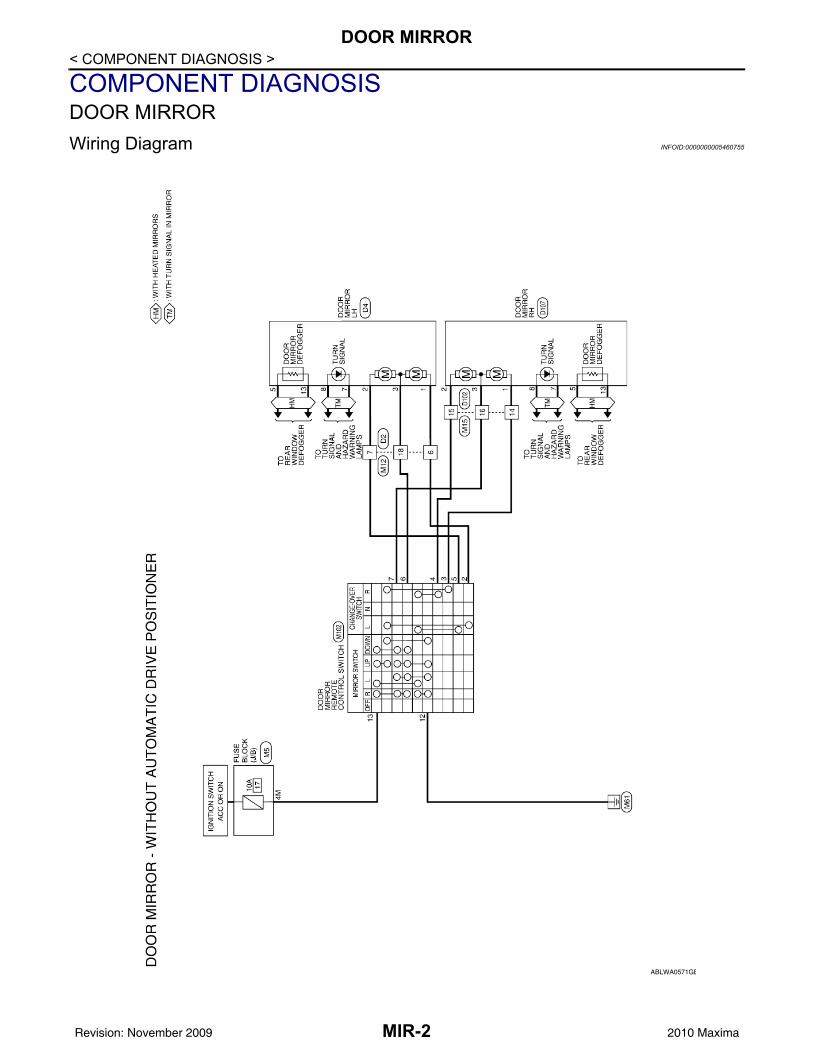
< COMPONENT DIAGNOSIS >COMPONENT DIAGNOSISDOOR MIRRORWiring Diagram INFOID:0000000005460755
ABLWA0571GB
MIR-2Revision: November 2009 2010 Maxima

DOOR MIRROR
C
D
E
F
G
H
I
J
K
M
A
B
IR
N
O
P
< COMPONENT DIAGNOSIS >
M
ABLIA1705GB
MIR-3Revision: November 2009 2010 Maxima

DOOR MIRROR
< COMPONENT DIAGNOSIS >ABLIA0533GB
MIR-4Revision: November 2009 2010 Maxima

AUTO ANTI-DAZZLING INSIDE MIRROR SYSTEM
C
D
E
F
G
H
I
J
K
M
A
B
IR
N
O
P
< COMPONENT DIAGNOSIS >
M
AUTO ANTI-DAZZLING INSIDE MIRROR SYSTEMWiring Diagram - Inside Mirror With Homelink Universal Transceiver INFOID:0000000005460756
ABLWA0149GB
MIR-5Revision: November 2009 2010 Maxima

AUTO ANTI-DAZZLING INSIDE MIRROR SYSTEM
< COMPONENT DIAGNOSIS >ABLIA0534GB
MIR-6Revision: November 2009 2010 Maxima

AUTO ANTI-DAZZLING INSIDE MIRROR SYSTEM
C
D
E
F
G
H
I
J
K
M
A
B
IR
N
O
P
< COMPONENT DIAGNOSIS >
M
ABLIA0535GB
MIR-7Revision: November 2009 2010 Maxima

AUTO ANTI-DAZZLING INSIDE MIRROR SYSTEM
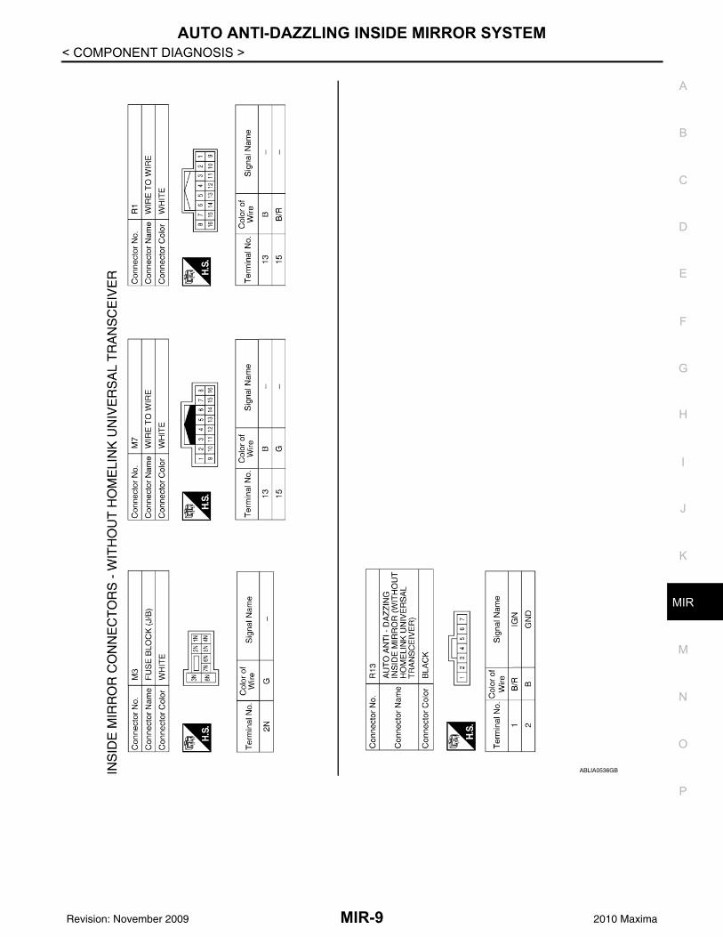
< COMPONENT DIAGNOSIS >Wiring Diagram - Inside Mirror Without Homelink Universal Transceiver INFOID:0000000005460757ABLWA0150GB
MIR-8Revision: November 2009 2010 Maxima
AUTO ANTI-DAZZLING INSIDE MIRROR SYSTEM
C
D
E
F
G
H
I
J
K
M
A
B
IR
N
O
P
< COMPONENT DIAGNOSIS >
M
ABLIA0536GB
MIR-9Revision: November 2009 2010 Maxima
SQUEAK AND RATTLE TROUBLE DIAGNOSES
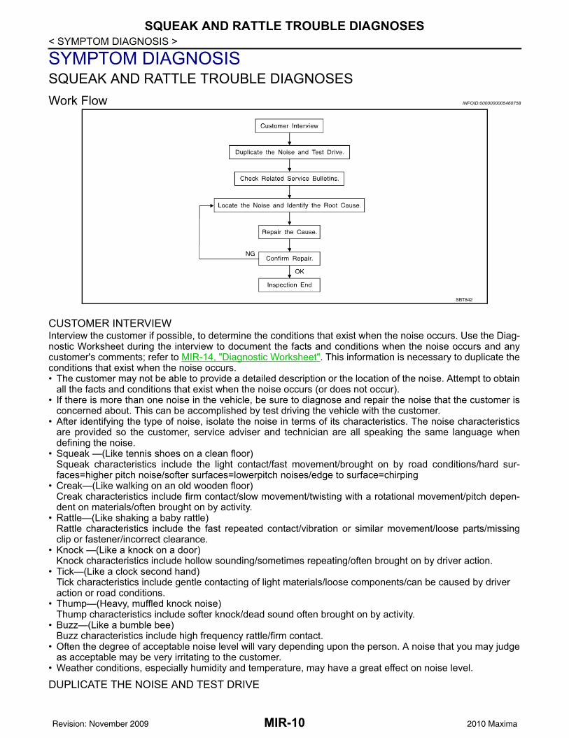
< SYMPTOM DIAGNOSIS >SYMPTOM DIAGNOSISSQUEAK AND RATTLE TROUBLE DIAGNOSESWork Flow INFOID:0000000005460758
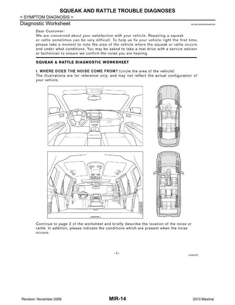
CUSTOMER INTERVIEWInterview the customer if possible, to determine the conditions that exist when the noise occurs. Use the Diag-nostic Worksheet during the interview to document the facts and conditions when the noise occurs and anycustomer's comments; refer to MIR-14, "Diagnostic Worksheet". This information is necessary to duplicate theconditions that exist when the noise occurs.• The customer may not be able to provide a detailed description or the location of the noise. Attempt to obtain
all the facts and conditions that exist when the noise occurs (or does not occur).• If there is more than one noise in the vehicle, be sure to diagnose and repair the noise that the customer is
concerned about. This can be accomplished by test driving the vehicle with the customer.• After identifying the type of noise, isolate the noise in terms of its characteristics. The noise characteristics
are provided so the customer, service adviser and technician are all speaking the same language whendefining the noise.
• Squeak —(Like tennis shoes on a clean floor)Squeak characteristics include the light contact/fast movement/brought on by road conditions/hard sur-faces=higher pitch noise/softer surfaces=lowerpitch noises/edge to surface=chirping
• Creak—(Like walking on an old wooden floor)Creak characteristics include firm contact/slow movement/twisting with a rotational movement/pitch depen-dent on materials/often brought on by activity.
• Rattle—(Like shaking a baby rattle)Rattle characteristics include the fast repeated contact/vibration or similar movement/loose parts/missingclip or fastener/incorrect clearance.
• Knock —(Like a knock on a door)Knock characteristics include hollow sounding/sometimes repeating/often brought on by driver action.
• Tick—(Like a clock second hand)Tick characteristics include gentle contacting of light materials/loose components/can be caused by driveraction or road conditions.
• Thump—(Heavy, muffled knock noise)Thump characteristics include softer knock/dead sound often brought on by activity.
• Buzz—(Like a bumble bee)Buzz characteristics include high frequency rattle/firm contact.
• Often the degree of acceptable noise level will vary depending upon the person. A noise that you may judgeas acceptable may be very irritating to the customer.
• Weather conditions, especially humidity and temperature, may have a great effect on noise level.
DUPLICATE THE NOISE AND TEST DRIVE
SBT842
MIR-10Revision: November 2009 2010 Maxima

SQUEAK AND RATTLE TROUBLE DIAGNOSES
C
D
E
F
G
H
I
J
K
M
A
B
IR
N
O
P
< SYMPTOM DIAGNOSIS >
M
If possible, drive the vehicle with the customer until the noise is duplicated. Note any additional information onthe Diagnostic Worksheet regarding the conditions or location of the noise. This information can be used toduplicate the same conditions when you confirm the repair.If the noise can be duplicated easily during the test drive, to help identify the source of the noise, try to dupli-cate the noise with the vehicle stopped by doing one or all of the following:1) Close a door.2) Tap or push/pull around the area where the noise appears to be coming from.3) Rev the engine.4) Use a floor jack to recreate vehicle “twist”.5) At idle, apply engine load (electrical load, half-clutch on M/T models, drive position on CVT models).6) Raise the vehicle on a hoist and hit a tire with a rubber hammer.• Drive the vehicle and attempt to duplicate the conditions the customer states exist when the noise occurs.• If it is difficult to duplicate the noise, drive the vehicle slowly on an undulating or rough road to stress the
vehicle body.
CHECK RELATED SERVICE BULLETINSAfter verifying the customer concern or symptom, check ASIST for Technical Service Bulletins (TSBs) relatedto that concern or symptom.If a TSB relates to the symptom, follow the procedure to repair the noise.
LOCATE THE NOISE AND IDENTIFY THE ROOT CAUSE1. Narrow down the noise to a general area. To help pinpoint the source of the noise, use a listening tool
(Chassis Ear: J-39570, Engine Ear and mechanics stethoscope).2. Narrow down the noise to a more specific area and identify the cause of the noise by:• removing the components in the area that you suspect the noise is coming from.
Do not use too much force when removing clips and fasteners, otherwise clips and fastener can be brokenor lost during the repair, resulting in the creation of new noise.
• tapping or pushing/pulling the component that you suspect is causing the noise.Do not tap or push/pull the component with excessive force, otherwise the noise will be eliminated only tem-porarily.
• feeling for a vibration with your hand by touching the component(s) that you suspect is (are) causing thenoise.
• placing a piece of paper between components that you suspect are causing the noise.• looking for loose components and contact marks.
Refer to MIR-12, "Generic Squeak and Rattle Troubleshooting".
REPAIR THE CAUSE• If the cause is a loose component, tighten the component securely.• If the cause is insufficient clearance between components:- separate components by repositioning or loosening and retightening the component, if possible.- insulate components with a suitable insulator such as urethane pads, foam blocks, felt cloth tape or urethane
tape. A Nissan Squeak and Rattle Kit (J-43980) is available through your authorized Nissan Parts Depart-ment.
CAUTION:Do not use excessive force as many components are constructed of plastic and may be damaged.NOTE:Always check with the Parts Department for the latest parts information.The following materials are contained in the Nissan Squeak and Rattle Kit (J-43980). Each item can beordered separately as needed.URETHANE PADS [1.5 mm (0.059 in) thick]Insulates connectors, harness, etc.76268-9E005: 100 × 135 mm (3.94 × 5.31 in)/76884-71L01: 60 × 85 mm (2.36 × 3.35 in)/76884-71L02: 15 × 25 mm (0.59 × 0.98 in)INSULATOR (Foam blocks)Insulates components from contact. Can be used to fill space behind a panel.73982-9E000: 45 mm (1.77 in) thick, 50 × 50 mm (1.97 × 1.97 in)/73982-50Y00: 10 mm (0.39 in) thick, 50 × 50 mm (1.97 × 1.97 in)INSULATOR (Light foam block)80845-71L00: 30 mm (1.18 in) thick, 30 × 50 mm (1.18 × 1.97 in)FELT CLOTHTAPEUsed to insulate where movement does not occur. Ideal for instrument panel applications.
MIR-11Revision: November 2009 2010 Maxima
SQUEAK AND RATTLE TROUBLE DIAGNOSES
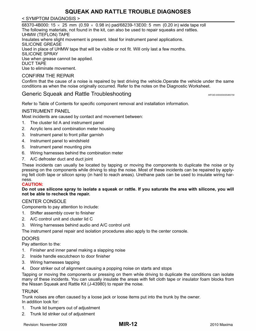
< SYMPTOM DIAGNOSIS >68370-4B000: 15 × 25 mm (0.59 × 0.98 in) pad/68239-13E00: 5 mm (0.20 in) wide tape rollThe following materials, not found in the kit, can also be used to repair squeaks and rattles.UHMW (TEFLON) TAPEInsulates where slight movement is present. Ideal for instrument panel applications.SILICONE GREASEUsed in place of UHMW tape that will be visible or not fit. Will only last a few months.SILICONE SPRAYUse when grease cannot be applied.DUCT TAPEUse to eliminate movement.CONFIRM THE REPAIRConfirm that the cause of a noise is repaired by test driving the vehicle.Operate the vehicle under the sameconditions as when the noise originally occurred. Refer to the notes on the Diagnostic Worksheet.
Generic Squeak and Rattle Troubleshooting INFOID:0000000005460759
Refer to Table of Contents for specific component removal and installation information.
INSTRUMENT PANELMost incidents are caused by contact and movement between:1. The cluster lid A and instrument panel2. Acrylic lens and combination meter housing3. Instrument panel to front pillar garnish4. Instrument panel to windshield5. Instrument panel mounting pins6. Wiring harnesses behind the combination meter7. A/C defroster duct and duct jointThese incidents can usually be located by tapping or moving the components to duplicate the noise or bypressing on the components while driving to stop the noise. Most of these incidents can be repaired by apply-ing felt cloth tape or silicon spray (in hard to reach areas). Urethane pads can be used to insulate wiring har-ness.CAUTION:Do not use silicone spray to isolate a squeak or rattle. If you saturate the area with silicone, you willnot be able to recheck the repair.
CENTER CONSOLEComponents to pay attention to include:1. Shifter assembly cover to finisher2. A/C control unit and cluster lid C3. Wiring harnesses behind audio and A/C control unitThe instrument panel repair and isolation procedures also apply to the center console.
DOORSPay attention to the:1. Finisher and inner panel making a slapping noise2. Inside handle escutcheon to door finisher3. Wiring harnesses tapping4. Door striker out of alignment causing a popping noise on starts and stopsTapping or moving the components or pressing on them while driving to duplicate the conditions can isolatemany of these incidents. You can usually insulate the areas with felt cloth tape or insulator foam blocks fromthe Nissan Squeak and Rattle Kit (J-43980) to repair the noise.
TRUNKTrunk noises are often caused by a loose jack or loose items put into the trunk by the owner.In addition look for:1. Trunk lid bumpers out of adjustment2. Trunk lid striker out of adjustment
MIR-12Revision: November 2009 2010 Maxima

SQUEAK AND RATTLE TROUBLE DIAGNOSES
C
D
E
F
G
H
I
J
K
M
A
B
IR
N
O
P
< SYMPTOM DIAGNOSIS >
M
3. The trunk lid torsion bars knocking together4. A loose license plate or bracketMost of these incidents can be repaired by adjusting, securing or insulating the item(s) or component(s) caus-ing the noise.
SUNROOF/HEADLININGNoises in the sunroof/headlining area can often be traced to one of the following:1. Sunroof lid, rail, linkage or seals making a rattle or light knocking noise2. Sunvisor shaft shaking in the holder3. Front or rear windshield touching headlining and squeakingAgain, pressing on the components to stop the noise while duplicating the conditions can isolate most of theseincidents. Repairs usually consist of insulating with felt cloth tape.
SEATSWhen isolating seat noise it's important to note the position the seat is in and the load placed on the seat whenthe noise is present. These conditions should be duplicated when verifying and isolating the cause of thenoise.Cause of seat noise include:1. Headrest rods and holder2. A squeak between the seat pad cushion and frame3. The rear seatback lock and bracketThese noises can be isolated by moving or pressing on the suspected components while duplicating the con-ditions under which the noise occurs.Most of these incidents can be repaired by repositioning the componentor applying urethane tape to the contact area.
UNDERHOODSome interior noise may be caused by components under the hood or on the engine wall. The noise is thentransmitted into the passenger compartment.Causes of transmitted underhood noise include:1. Any component mounted to the engine wall2. Components that pass through the engine wall3. Engine wall mounts and connectors4. Loose radiator mounting pins5. Hood bumpers out of adjustment6. Hood striker out of adjustmentThese noises can be difficult to isolate since they cannot be reached from the interior of the vehicle. The bestmethod is to secure, move or insulate one component at a time and test drive the vehicle. Also, engine RPMor load can be changed to isolate the noise. Repairs can usually be made by moving, adjusting, securing, orinsulating the component causing the noise.
MIR-13Revision: November 2009 2010 Maxima
SQUEAK AND RATTLE TROUBLE DIAGNOSES
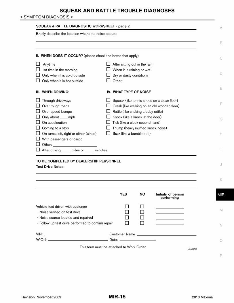
< SYMPTOM DIAGNOSIS >Diagnostic Worksheet INFOID:0000000005460760LAIA0072E
MIR-14Revision: November 2009 2010 Maxima
SQUEAK AND RATTLE TROUBLE DIAGNOSES
C
D
E
F
G
H
I
J
K
M
A
B
IR
N
O
P
< SYMPTOM DIAGNOSIS >
M
LAIA0071E
MIR-15Revision: November 2009 2010 Maxima

PRECAUTIONS
< PRECAUTION >PRECAUTIONPRECAUTIONSPrecaution for Supplemental Restraint System (SRS) "AIR BAG" and "SEAT BELT PRE-TENSIONER" INFOID:0000000005460761
The Supplemental Restraint System such as “AIR BAG” and “SEAT BELT PRE-TENSIONER”, used alongwith a front seat belt, helps to reduce the risk or severity of injury to the driver and front passenger for certaintypes of collision. This system includes seat belt switch inputs and dual stage front air bag modules. The SRSsystem uses the seat belt switches to determine the front air bag deployment, and may only deploy one frontair bag, depending on the severity of a collision and whether the front occupants are belted or unbelted.Information necessary to service the system safely is included in the SR and SB section of this Service Man-ual.WARNING:• To avoid rendering the SRS inoperative, which could increase the risk of personal injury or death in
the event of a collision which would result in air bag inflation, all maintenance must be performed byan authorized NISSAN/INFINITI dealer.
• Improper maintenance, including incorrect removal and installation of the SRS, can lead to personalinjury caused by unintentional activation of the system. For removal of Spiral Cable and Air BagModule, see the SR section.
• Do not use electrical test equipment on any circuit related to the SRS unless instructed to in thisService Manual. SRS wiring harnesses can be identified by yellow and/or orange harnesses or har-ness connectors.
PRECAUTIONS WHEN USING POWER TOOLS (AIR OR ELECTRIC) AND HAMMERSWARNING:• When working near the Airbag Diagnosis Sensor Unit or other Airbag System sensors with the Igni-
tion ON or engine running, DO NOT use air or electric power tools or strike near the sensor(s) with ahammer. Heavy vibration could activate the sensor(s) and deploy the air bag(s), possibly causingserious injury.
• When using air or electric power tools or hammers, always switch the Ignition OFF, disconnect thebattery, and wait at least 3 minutes before performing any service.
Precautions Necessary for Steering Wheel Rotation after Battery Disconnect (Early Production, With Electronic Steering Column Lock) INFOID:0000000005885950
NOTE:• Before removing and installing any control units, first turn the push-button ignition switch to the LOCK posi-
tion, then disconnect both battery cables.• After finishing work, confirm that all control unit connectors are connected properly, then re-connect both
battery cables.• Always use CONSULT-III to perform self-diagnosis as a part of each function inspection after finishing work.
If a DTC is detected, perform trouble diagnosis according to self-diagnosis results.This vehicle is equipped with a push-button ignition switch and a steering lock unit.If the battery is disconnected or discharged, the steering wheel will lock and cannot be turned.If turning the steering wheel is required with the battery disconnected or discharged, follow the procedurebelow before starting the repair operation.
OPERATION PROCEDURE1. Connect both battery cables.
NOTE:Supply power using jumper cables if battery is discharged.
2. Carry the Intelligent Key or insert it to the key slot and turn the push-button ignition switch to ACC position.(At this time, the steering lock will be released.)
3. Disconnect both battery cables. The steering lock will remain released with both battery cables discon-nected and the steering wheel can be turned.
4. Perform the necessary repair operation.
MIR-16Revision: November 2009 2010 Maxima
PRECAUTIONS
C
D
E
F
G
H
I
J
K
M
A
B
IR
N
O
P
< PRECAUTION >
M
5. When the repair work is completed, re-connect both battery cables. With the brake pedal released, turnthe push-button ignition switch from ACC position to ON position, then to LOCK position. (The steeringwheel will lock when the push-button ignition switch is turned to LOCK position.)
6. Perform self-diagnosis check of all control units using CONSULT-III.
MIR-17Revision: November 2009 2010 Maxima

PREPARATION
< PREPARATION >PREPARATIONPREPARATIONCommercial Service Tools INFOID:0000000005460763
Tool name Description
Engine ear Locating the noise
SIIA0995E
MIR-18Revision: November 2009 2010 Maxima
INSIDE MIRROR
C
D
E
F
G
H
I
J
K
M
A
B
IR
N
O
P
< ON-VEHICLE REPAIR >
M
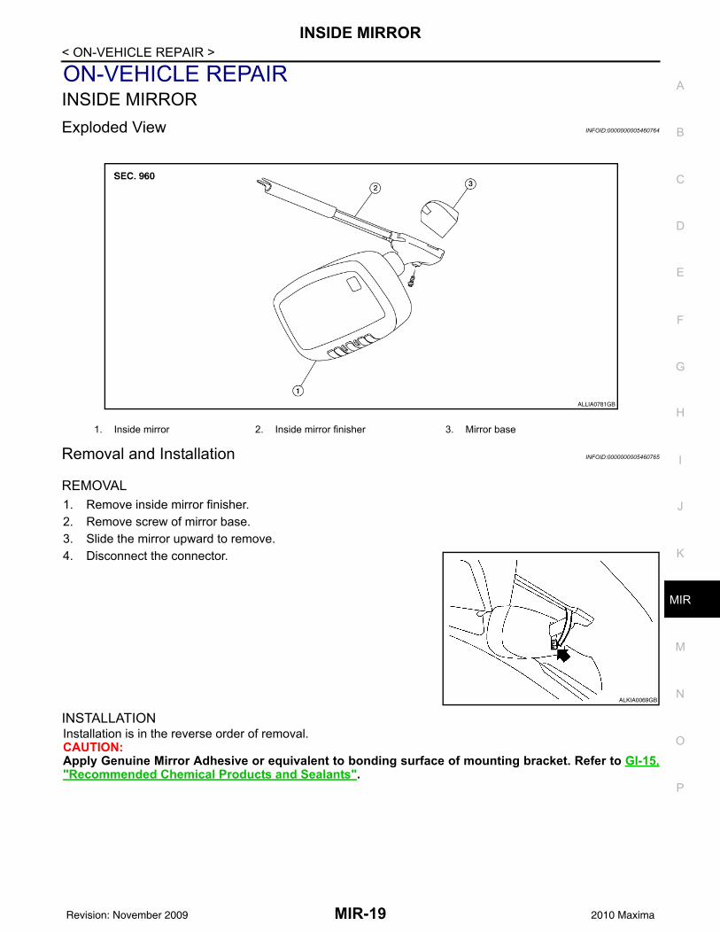
ON-VEHICLE REPAIRINSIDE MIRRORExploded View INFOID:0000000005460764
Removal and Installation INFOID:0000000005460765
REMOVAL1. Remove inside mirror finisher.2. Remove screw of mirror base.3. Slide the mirror upward to remove.4. Disconnect the connector.
INSTALLATIONInstallation is in the reverse order of removal.CAUTION:Apply Genuine Mirror Adhesive or equivalent to bonding surface of mounting bracket. Refer to GI-15,"Recommended Chemical Products and Sealants".
1. Inside mirror 2. Inside mirror finisher 3. Mirror base
ALLIA0781GB
ALKIA0069GB
MIR-19Revision: November 2009 2010 Maxima

DOOR MIRROR
< ON-VEHICLE REPAIR >DOOR MIRRORExploded View INFOID:0000000005460766Removal and Installation INFOID:0000000005460767
REMOVAL1. Remove the front door finisher. Refer to INT-18, "Removal and Installation".2. Remove the mirror cover.3. Disconnect the door mirror harness connector.4. Remove the door mirror nuts, and remove the door mirror assembly.
INSTALLATIONInstallation is in the reverse order of removal.
1. Door panel 2. Nuts 3. Mirror cover4. Mirror assembly Clip C101
ALLIA0875GB
MIR-20Revision: November 2009 2010 Maxima
DOOR MIRROR
C
D
E
F
G
H
I
J
K
M
A
B
IR
N
O
P
< DISASSEMBLY AND ASSEMBLY >
M
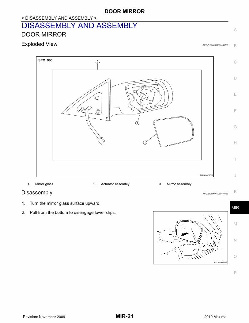
DISASSEMBLY AND ASSEMBLYDOOR MIRRORExploded View INFOID:0000000005460768
Disassembly INFOID:0000000005460769
1. Turn the mirror glass surface upward.
2. Pull from the bottom to disengage lower clips.
1. Mirror glass 2. Actuator assembly 3. Mirror assembly
ALLIA0876GB
ALLIA0877GB
MIR-21Revision: November 2009 2010 Maxima
DOOR MIRROR
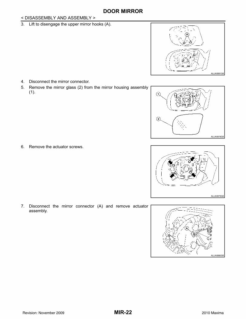
< DISASSEMBLY AND ASSEMBLY >3. Lift to disengage the upper mirror hooks (A).4. Disconnect the mirror connector.5. Remove the mirror glass (2) from the mirror housing assembly
(1).
6. Remove the actuator screws.
7. Disconnect the mirror connector (A) and remove actuatorassembly.
ALLIA0881GB
ALLIA0878GB
ALLIA0879GB
ALLIA0880GB
MIR-22Revision: November 2009 2010 Maxima

DOOR MIRROR
C
D
E
F
G
H
I
J
K
M
A
B
IR
N
O
P
< DISASSEMBLY AND ASSEMBLY >
M
8. Disengage the pawls and remove the mirror cover from the mir-ror assembly.
Assembly INFOID:0000000005460770
Assembly is in the reverse order of disassembly.DOOR MIRROR COVERDOOR MIRROR COVER : Disassembly INFOID:0000000005460771
1. Using a suitable tool disengage the upper mirror cover pawls.
2. Using a suitable tool disengage the lower mirror cover pawlsand remove mirror cover.
CAUTION:Be careful not to damage the mirror or mirror cover with tool.
DOOR MIRROR COVER : Assembly INFOID:0000000005460772
Assembly is in the reverse order of disassembly.CAUTION:After installation, check that pawls are securely engaged.
Pawl
ALLIA0882GB
Pawl
ALLIA0895ZZ
MIR-23Revision: November 2009 2010 Maxima