zero crossing counter for accuracy improvement of fmcw
TRANSCRIPT
Turk J Elec Engin, VOL.16, NO.2 2008, c© TUBITAK
Zero Crossing Counter for Accuracy Improvement of
FMCW Range Detection
Sinan KURT1, Simsek DEMIR2, Altunkan HIZAL2
1TUBITAK-UZAY, Middle East Technical University, Campus, Ankara-TURKEY2Middle East Tecnical University, Electrical and Electronics Engineering, Ankara-TURKEY
e-mail: [email protected], [email protected], [email protected]
Abstract
For civil and military purposes FMCW radars are widely used. The theoretical background is well-
established. Nevertheless, improvement of various aspects of these radars is still required. Signal pro-
cessing is one of the crucial points of the system which determines the capabilities of the radar. In
this study a zero crossing detector implementation, which can be efficiently used for target detection and
range calculation in short range FMCW range detector is proposed. The duration between consecutive
zero-crossings are used as the data instead of the number of cycles per unit time. Experimental evaluation
of its performance is also given.
1. Introduction
FMCW radars are being used for many civil and military applications including smart ammunition sensors,vehicle collision avoidance and industrial control [1]. Specifically, the short range applications can be listedbut not limited to the followings: collision avoidance, proximity fuse, level measuring of liquid tanks andhidden object detection. The main advantages of the FMCW radars for such applications are due to theirability to measure very small ranges with small range errors. Light weight, low energy consumption and thecompactness of the circuitry are additional advantages [2].
The signal processing can be done either in frequency domain or in the time domain. The most widelyused frequency domain methods are FFT based. There are works on reducing the computational load of FFTprocessing [3] and increasing the range resolution [4] and accuracy [5]. Besides FFT, some novel methods of
parameter estimation for moving targets are present [6]. In addition, the high-resolution spectral estimation
methods such as MUSIC, AR, ARMA and neural network algorithm are also used for FMCW radars [7-10].All these methods have a trade off between computational load and range measurement improvement. Themethods analyzing the signal in time domain is mainly based on discrimination by zero crossing. In the earlyyears in which spectral methods were popular for FMCW signal processing, there had been works about thetime domain analysis and the comparison of two methods [11-12].
All the mentioned method implementations are capable of discrimination of multiple targets and havecomplex circuitry. Nevertheless, for a low cost system, the signal-processing unit should be compatiblewith the simple circuit structure and compactness of the radar. In the applications that require the rangeinformation of a specific target such as level gauging, radio altimeter etc. FMCW range detectors with zero
125
Turk J Elec Engin, VOL.16, NO.2, 2008
crossing counters can be used. The simple circuitry and low cost implementations as compared to othersignal processing unit implementations will be the benefits of this choice. Various ZCC implementations arepossible. In this study, a zero-crossing counter with improved range accuracy is suggested. While preservingthe simple and low cost implementation, our ZCC is better in range accuracy than the conventional cyclecounters, which are used for FMCW range detectors [12].
In the following sections, firstly, the basic FMCW principle is given and then ZCC implementationis discussed. After that, range accuracy calculations are given for a general cycle counter and for our ZCCimplementation. Finally, the experimental setup and measurement results are given, for discussing the ZCCperformance analysis.
2. Basic FMCW Principle
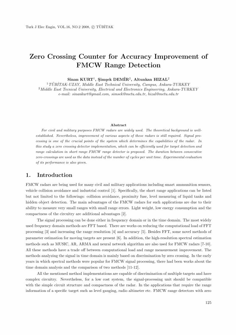
In FMCW radars, the frequency difference between the frequency modulated transmitted signal and thereceived echo signal is measured, and named as the beat frequency. Beat frequency is a direct measureof the range for linearly increasing frequency. In practice, the linear increase of frequency is realized bytriangular frequency modulation, which results in distortions in the beat signal. Figure 1 shows the signalsfor triangular modulation and the corresponding beat frequencyfb .
The range and the beat frequency relation can be obtained by simple trigonometric relations andusing the fact that time delay is T = 2R/c , as follows:
fb = T · mf =2R
c· mf (1)
where mf is the slope of the frequency change and:
mf =Δf
1/2fm= 2fmΔf (2)
Using (1) and (2)
R =c
4fmΔf· fb (3)
freq
uenc
yB
eat f
requ
ency
time
f0
Td
fb
Δf
Tm/4
1/fm
3Tm/4
Real frequencyComplex frequency
EchoSignal
TransmittedSignal
fb
Figure 1. Triangular modulated FMCW signals and corresponding beat frequency.
126
KURT1 , Simsek DEMIR2 , Altunkan HIZAL: Zero Crossing Counter for Accuracy Improvement...,
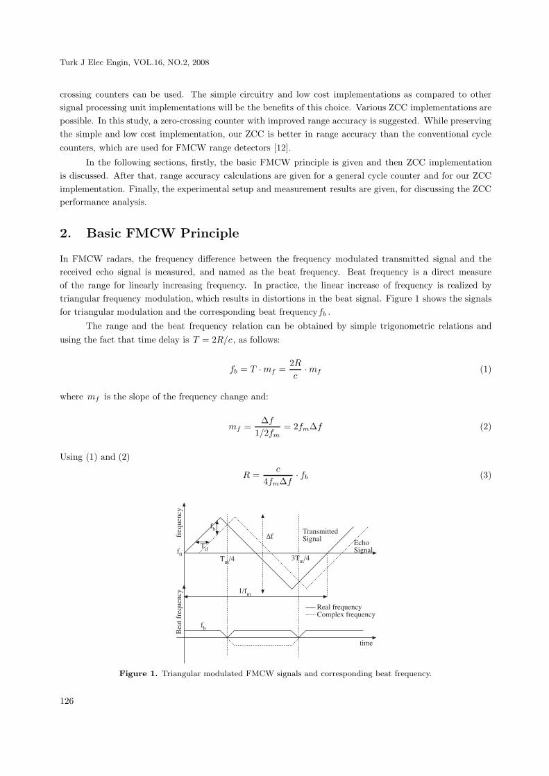
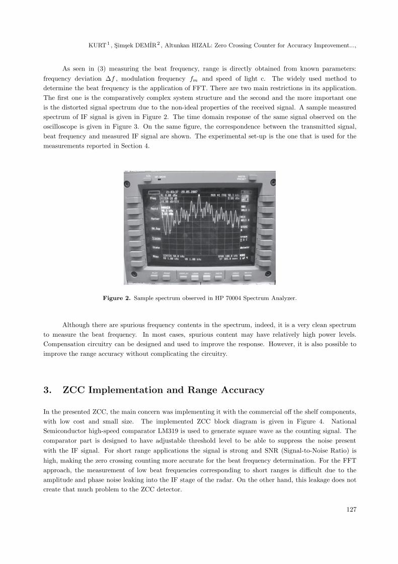
As seen in (3) measuring the beat frequency, range is directly obtained from known parameters:frequency deviation Δf , modulation frequency fm and speed of light c. The widely used method todetermine the beat frequency is the application of FFT. There are two main restrictions in its application.The first one is the comparatively complex system structure and the second and the more important oneis the distorted signal spectrum due to the non-ideal properties of the received signal. A sample measuredspectrum of IF signal is given in Figure 2. The time domain response of the same signal observed on theoscilloscope is given in Figure 3. On the same figure, the correspondence between the transmitted signal,beat frequency and measured IF signal are shown. The experimental set-up is the one that is used for themeasurements reported in Section 4.
Figure 2. Sample spectrum observed in HP 70004 Spectrum Analyzer.
Although there are spurious frequency contents in the spectrum, indeed, it is a very clean spectrumto measure the beat frequency. In most cases, spurious content may have relatively high power levels.Compensation circuitry can be designed and used to improve the response. However, it is also possible toimprove the range accuracy without complicating the circuitry.
3. ZCC Implementation and Range Accuracy
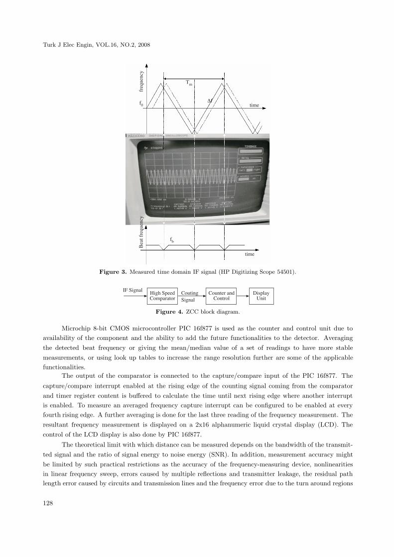
In the presented ZCC, the main concern was implementing it with the commercial off the shelf components,with low cost and small size. The implemented ZCC block diagram is given in Figure 4. NationalSemiconductor high-speed comparator LM319 is used to generate square wave as the counting signal. Thecomparator part is designed to have adjustable threshold level to be able to suppress the noise presentwith the IF signal. For short range applications the signal is strong and SNR (Signal-to-Noise Ratio) ishigh, making the zero crossing counting more accurate for the beat frequency determination. For the FFTapproach, the measurement of low beat frequencies corresponding to short ranges is difficult due to theamplitude and phase noise leaking into the IF stage of the radar. On the other hand, this leakage does notcreate that much problem to the ZCC detector.
127
Turk J Elec Engin, VOL.16, NO.2, 2008
freq
uenc
yB
eat f
requ
ency
time
Δf
fb
time
Tm
f0
Figure 3. Measured time domain IF signal (HP Digitizing Scope 54501).
IF Signal High SpeedComparator
CoutingSignal
Counter andControl
DisplayUnit
Figure 4. ZCC block diagram.
Microchip 8-bit CMOS microcontroller PIC 16f877 is used as the counter and control unit due toavailability of the component and the ability to add the future functionalities to the detector. Averagingthe detected beat frequency or giving the mean/median value of a set of readings to have more stablemeasurements, or using look up tables to increase the range resolution further are some of the applicablefunctionalities.
The output of the comparator is connected to the capture/compare input of the PIC 16f877. The
capture/compare interrupt enabled at the rising edge of the counting signal coming from the comparatorand timer register content is buffered to calculate the time until next rising edge where another interruptis enabled. To measure an averaged frequency capture interrupt can be configured to be enabled at everyfourth rising edge. A further averaging is done for the last three reading of the frequency measurement. Theresultant frequency measurement is displayed on a 2x16 alphanumeric liquid crystal display (LCD). Thecontrol of the LCD display is also done by PIC 16f877.
The theoretical limit with which distance can be measured depends on the bandwidth of the transmit-ted signal and the ratio of signal energy to noise energy (SNR). In addition, measurement accuracy mightbe limited by such practical restrictions as the accuracy of the frequency-measuring device, nonlinearitiesin linear frequency sweep, errors caused by multiple reflections and transmitter leakage, the residual pathlength error caused by circuits and transmission lines and the frequency error due to the turn around regions
128
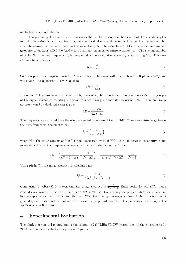
KURT1 , Simsek DEMIR2 , Altunkan HIZAL: Zero Crossing Counter for Accuracy Improvement...,
of the frequency modulation.
If a general cycle counter, which measures the number of cycles or half cycles of the beat during themodulation period, is used as a frequency-measuring device then the total cycle count is a discrete numbersince the counter is unable to measure fractions of a cycle. The discreteness of the frequency measurementgives rise to an error called the fixed error, quantization error, or range accuracy [13]. The average number
of cycles N of the beat frequency fb in one period of the modulation cycle fm is equal to fb/fm . Therefore
(3) may be written as:
R =cN
4Δf(4)
Since output of the frequency counter N is an integer, the range will be an integer multiple of c/4Δf andwill give rise to quantization error equal to:
δR =c
4Δf(5)
In our ZCC, beat frequency is calculated by measuring the time interval between successive rising edgesof the signal instead of counting the zero crossings during the modulation period, Tm . Therefore, rangeaccuracy can be calculated using (3) as:
δR =c · δfb
4Δf · fm(6)
The frequency is calculated from the counter content difference of the PIC16F877 for every rising edge hence,the beat frequency is calculated as:
fb =(
1N · ΔT
)(7)
where N is the timer content and ΔT is the instruction cycle of PIC, i.e. time between consecutive timerincrements. Hence, the frequency accuracy can be calculated for our ZCC as:
δfb =(
1(N + 1) ·ΔT
− 1N · ΔT
)=
1(N + 1) · N · ΔT
=fb
N + 1(8)
Using (6) in (7), the range accuracy is calculated as:
δR =c · fb
4Δf · fm · (N + 1)(9)
Comparing (9) with (5), it is seen that the range accuracy is fb
fm·(N+1) times better for our ZCC than a
general cycle counter. The instruction cycle ΔT is 200 ns. Considering the proper values for fb and fm
in the experimental setup it is seen that our ZCC has a range accuracy at least 6 times better than ageneral cycle counter and can further be increased by proper adjustment of the parameters according to theapplication specifications.
4. Experimental Evaluation
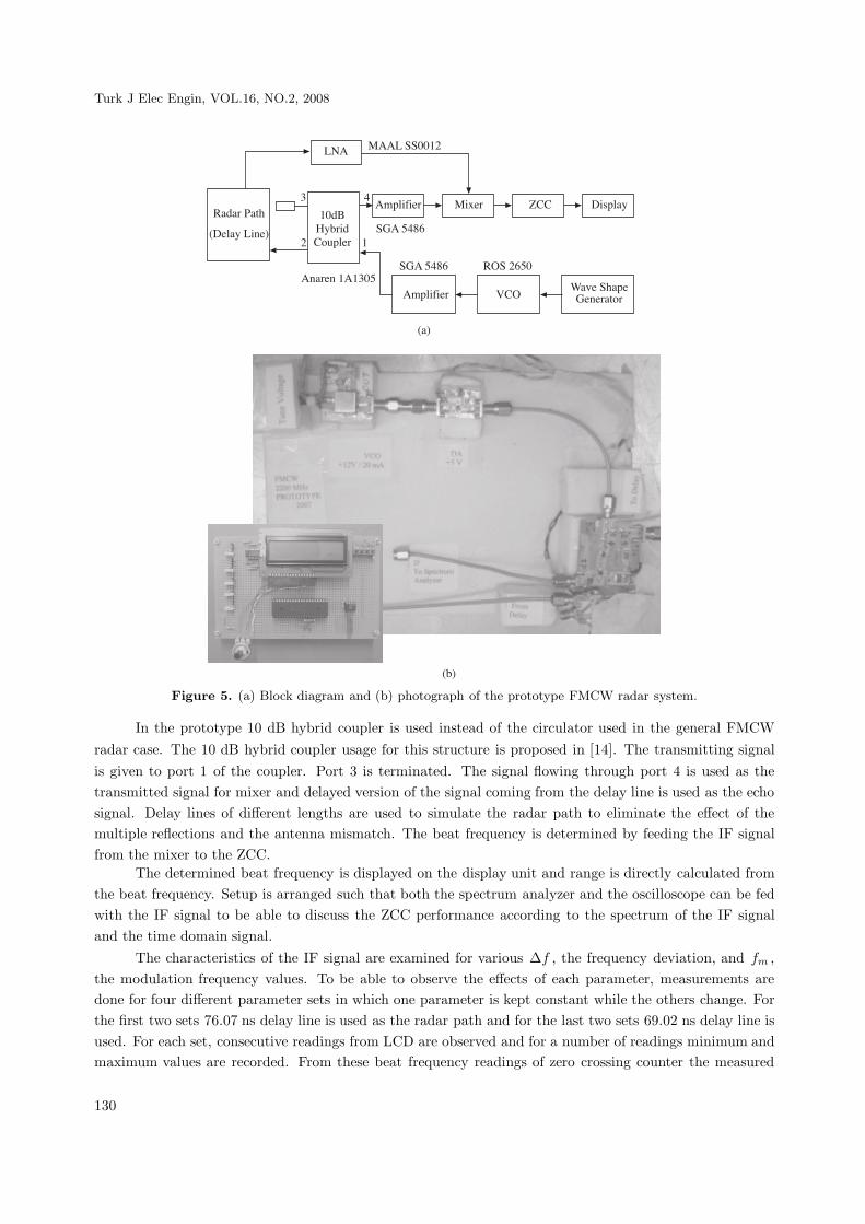
The block diagram and photograph of the prototype 2200 MHz FMCW system used in the experiments forZCC measurement evaluation is given in Figure 5.
129
Turk J Elec Engin, VOL.16, NO.2, 2008
LNA MAAL SS0012
3 4Amplifier Mixer ZCC Display
12
SGA 5486 ROS 2650
Amplifier VCOWave ShapeGenerator
Anaren 1A1305
Radar Path
(Delay Line)
10dBHybridCoupler
SGA 5486
(a)
(b)
Figure 5. (a) Block diagram and (b) photograph of the prototype FMCW radar system.
In the prototype 10 dB hybrid coupler is used instead of the circulator used in the general FMCWradar case. The 10 dB hybrid coupler usage for this structure is proposed in [14]. The transmitting signalis given to port 1 of the coupler. Port 3 is terminated. The signal flowing through port 4 is used as thetransmitted signal for mixer and delayed version of the signal coming from the delay line is used as the echosignal. Delay lines of different lengths are used to simulate the radar path to eliminate the effect of themultiple reflections and the antenna mismatch. The beat frequency is determined by feeding the IF signalfrom the mixer to the ZCC.
The determined beat frequency is displayed on the display unit and range is directly calculated fromthe beat frequency. Setup is arranged such that both the spectrum analyzer and the oscilloscope can be fedwith the IF signal to be able to discuss the ZCC performance according to the spectrum of the IF signaland the time domain signal.
The characteristics of the IF signal are examined for various Δf , the frequency deviation, and fm ,the modulation frequency values. To be able to observe the effects of each parameter, measurements aredone for four different parameter sets in which one parameter is kept constant while the others change. Forthe first two sets 76.07 ns delay line is used as the radar path and for the last two sets 69.02 ns delay line isused. For each set, consecutive readings from LCD are observed and for a number of readings minimum andmaximum values are recorded. From these beat frequency readings of zero crossing counter the measured
130
KURT1 , Simsek DEMIR2 , Altunkan HIZAL: Zero Crossing Counter for Accuracy Improvement...,
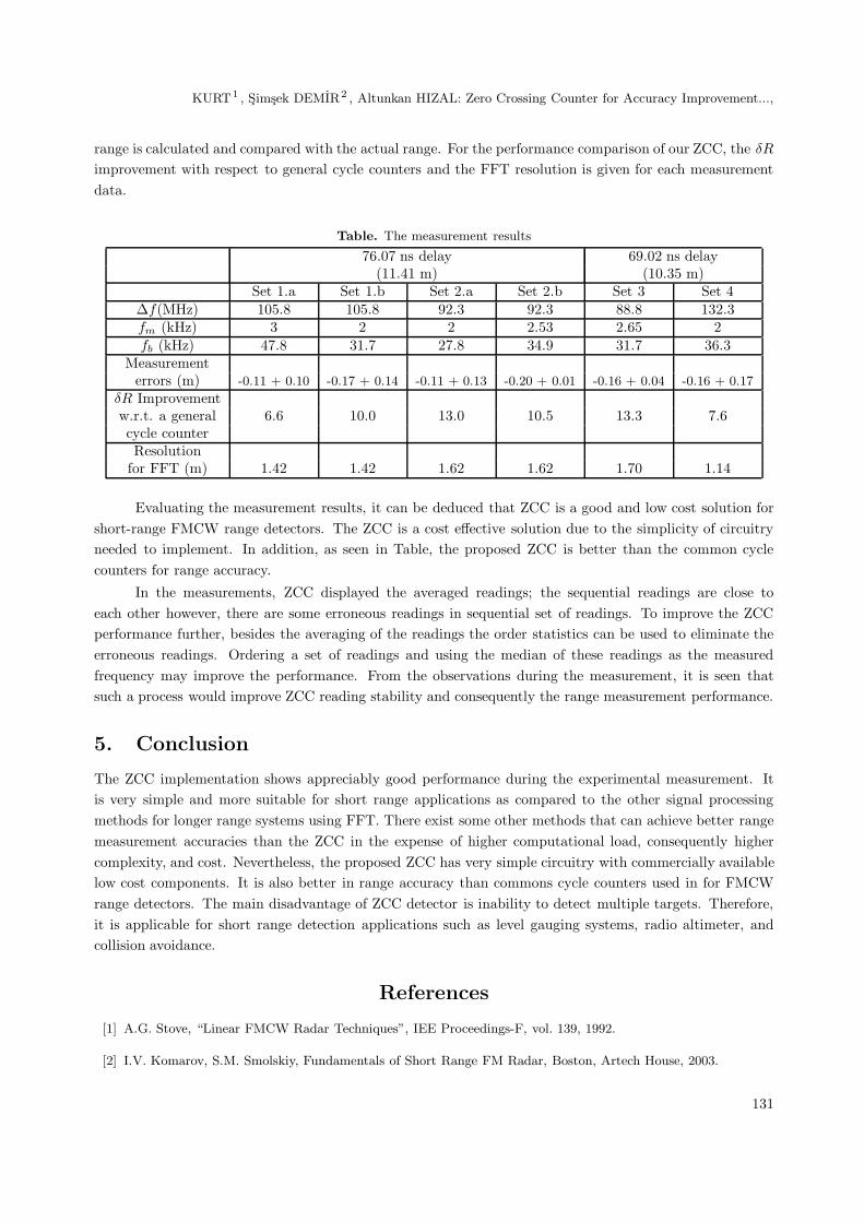
range is calculated and compared with the actual range. For the performance comparison of our ZCC, the δR
improvement with respect to general cycle counters and the FFT resolution is given for each measurementdata.
Table. The measurement results
76.07 ns delay 69.02 ns delay(11.41 m) (10.35 m)
Set 1.a Set 1.b Set 2.a Set 2.b Set 3 Set 4Δf(MHz) 105.8 105.8 92.3 92.3 88.8 132.3fm (kHz) 3 2 2 2.53 2.65 2fb (kHz) 47.8 31.7 27.8 34.9 31.7 36.3
Measurementerrors (m) -0.11 + 0.10 -0.17 + 0.14 -0.11 + 0.13 -0.20 + 0.01 -0.16 + 0.04 -0.16 + 0.17
δR Improvementw.r.t. a general 6.6 10.0 13.0 10.5 13.3 7.6cycle counterResolution
for FFT (m) 1.42 1.42 1.62 1.62 1.70 1.14
Evaluating the measurement results, it can be deduced that ZCC is a good and low cost solution forshort-range FMCW range detectors. The ZCC is a cost effective solution due to the simplicity of circuitryneeded to implement. In addition, as seen in Table, the proposed ZCC is better than the common cyclecounters for range accuracy.
In the measurements, ZCC displayed the averaged readings; the sequential readings are close toeach other however, there are some erroneous readings in sequential set of readings. To improve the ZCCperformance further, besides the averaging of the readings the order statistics can be used to eliminate theerroneous readings. Ordering a set of readings and using the median of these readings as the measuredfrequency may improve the performance. From the observations during the measurement, it is seen thatsuch a process would improve ZCC reading stability and consequently the range measurement performance.
5. Conclusion
The ZCC implementation shows appreciably good performance during the experimental measurement. Itis very simple and more suitable for short range applications as compared to the other signal processingmethods for longer range systems using FFT. There exist some other methods that can achieve better rangemeasurement accuracies than the ZCC in the expense of higher computational load, consequently highercomplexity, and cost. Nevertheless, the proposed ZCC has very simple circuitry with commercially availablelow cost components. It is also better in range accuracy than commons cycle counters used in for FMCWrange detectors. The main disadvantage of ZCC detector is inability to detect multiple targets. Therefore,it is applicable for short range detection applications such as level gauging systems, radio altimeter, andcollision avoidance.
References
[1] A.G. Stove, “Linear FMCW Radar Techniques”, IEE Proceedings-F, vol. 139, 1992.
[2] I.V. Komarov, S.M. Smolskiy, Fundamentals of Short Range FM Radar, Boston, Artech House, 2003.
131
Turk J Elec Engin, VOL.16, NO.2, 2008
[3] J. Liu, X. Chen, Z. Zhang, “A Novel Algorithm in the FMCW Microwave Liquid Level Measuring System”,
Measurement Science and Technology vol.17, pp. 135-138, 2006.
[4] D. L Maskell, G.S. Woods, J.M. Murray, “A Microprocessor Controlled Microwave Ranging System for High
Accuracy Industrial Applications”, IEEE Instrumentation and Measurement Technology Conference, IMTC
1994.
[5] G.S. Woods, D.L. Maskell, M.V. Mohaney, “A High Accuracy Microwave Ranging System for Industrial Appli-
cation”, IEEE Transactions on Instrumentation and Measurement, vol. 42, pp. 812-816, 1993.
[6] R. Zhang, J. Yang, J. Xiong, “Novel Method of Parameter Estimation for Moving Target in Millimeter-wave
Short-range Linear FMCW Radar”, 7th International Conference on Signal Processing Proceedings, ICSP 2004.
[7] M. Bouchard, D. Gingras, Y. De Villers, D. Potvin, “High Resolution Spectrum Estimation of FMCW Radar
Signals”, IEEE Seventh SP Workshop on Statistical Signal and Array Processing, 1994.
[8] L. Yang, L. Liwan, P. Weifeng, C. Yanqin, F. Zhenghe, “Performance Comparison of Super-resolution Estimation
Algorithms Used in Real or Complex LFMCW Systems”, International Conference on Microwave and Millimeter
Wave Technology Proceedings, 2000.
[9] S. De Waele, P.M.T. Broersen, “Modeling Radar Data with Time Series Models”, European Signal Processing
Conference X, EUPSICO 2000.
[10] H. Wensink, A. Bazen, “On Automatic Clutter Identification and Rejection”, IEEE Radar ’99, France1999.
[11] B. Kedem, “Spectral Analysis and Discrimination by Zero-Crossings”, Proceedings of IEE, vol. 74, pp 1477-1493,
1986.
[12] G.L. Cote, M.D. Fox, “Comparison of Zero Crossing Counter to FFT Spectrum of Ultrasound Doppler”, IEEE
Transactions on Biomedical Engineering, 1988.
[13] M.I. Skolnik, Introduction to Radar Systems, Singapore, McGraw-Hill Book Company, 1980 Second Edition.
[14] M. Secmen, S. Demir, A. Hizal, “Dual-polarised T/R Antenna System Suitable for FMCW Altimeter Radar
Applications”, IEE Proceedings Microwaves Antennas and Propagation, 2006.
132