wave-induced mean magnitudes in permeable submerged breakwaters
TRANSCRIPT
WAVE-INDUCED MEAN MAGNITUDES IN PERMEABLE
SUBMERGED BREAKWATERS
By Fernando J. Mendez,1 J. Losada,2 Member, ASCE,Inigoand Miguel A. Losada,3 Member, ASCE
ABSTRACT: The influence of wave reflection and energy dissipation by breaking and by porous flow inducedby a permeable submerged structure on second-order mean quantities such as mass flux, energy flux, radiationstress, and mean water level is analyzed. For this purpose, analytical expressions for those mean quantities interms of the shape functions are obtained. The dependence of those quantities on the incident wave character-istics, structure geometry, and permeable material characteristics is modeled, extending the writers’ previouswork including wave breaking. Two models for regular waves are presented: a 2D model to be applied tosubmerged trapezoidal breakwaters and a 3D model for submerged permeable rectangular breakwaters. Bothmodels are able to reproduce experimental wave height transformation as well as mean water level variationsalong the wave flume with reasonable accuracy. Results give useful information for engineering applications ofwave height evolution and set-up and set-down evolution in the vicinity of the submerged permeable structure.
INTRODUCTION
Submerged breakwaters have been widely used for coastalprotection as wave energy dissipators and sediment transportcontrollers. Energy dissipation is caused by two mechanisms:wave breaking and friction on the surface and inside the per-meable layer of the structure. Efficiency of the submergedbreakwater depends on the freeboard, the crest width, and thepermeable material characteristics. In regions of large tidalrange, reflection, transmission, and dissipation characteristicsmay change considerably during a tidal cycle.
Several models to describe wave transformation over sub-merged breakwaters have been presented in the literature. In-dependently of the extensive existing work for impermeablestructures, the influence of structure permeability has also beenaddressed in the last few years. In the following, some of thatwork is addressed.
Rojanakamthorn et al. (1989, 1990) presented a mathemat-ical model based on linear wave theory for a rectangular sub-merged breakwater and extended the solution in deriving amodified mild-slope equation, including wave breaking, toevaluate wave transformation over a trapezoidal porous break-water. Irregular waves were analyzed using an individual waveanalysis technique to calculate the transformation of each wavecomponent. Gu and Wang (1992), using a boundary integralelement method (BIEM), developed a numerical model forwave energy dissipation within porous submerged breakwatersbased on a linearized porous flow equation.
Losada et al. (1996a,b) assuming incompressible fluid andirrotational motion inside and outside the permeable structure,analyzed the interaction of submerged breakwaters with non-breaking oblique incident regular waves and directional ran-dom waves. The influence of structure geometry, porous ma-terial properties, and wave characteristics on the kinematics
1Postdoct. Res., Oc. and Coast. Res. Group, Universidad de Cantabria,Dpto. de Ciencias y Tecnicas del Agua y del Medio Ambiente, Av. delos Castros s/n, 39005 Santander, Spain.
2Prof., Oc. and Coast. Res. Group, Universidad de Cantabria, Dpto. deCiencias y Tecnicas del Agua y del Medio Ambiente, Av. de los Castross/n, 39005 Santander, Spain.
3Prof., Universidad de Granada, E.T.S.I. de Caminos, C.y.P. Campusde la Cartuja s/n, 18071 Granada, Spain.
Note. Discussion open until July 1, 2001. To extend the closing dateone month, a written request must be filed with the ASCE Manager ofJournals. The manuscript for this paper was submitted for review andpossible publication on August 13, 1998. This paper is part of the Journalof Waterway, Port, Coastal and Ocean Engineering, Vol. 127, No. 1,January/February, 2001. qASCE, ISSN 0733-950X/01/0001-0007–0015/$8.00 1 $.50 per page. Paper No. 19011.
JOURNAL OF WATERWAY, PORT, C
and dynamics over and inside the breakwaters is consideredin both papers.
Second-order theory was first presented for an impermeablestep by Massel (1983) where the growth of secondary har-monics was analyzed. Further research on nonlinear effectscan be found in Rey et al. (1992), Ohyama and Nadaoka(1992), and Eldeberky and Battjes (1994) for impermeablesubmerged structures. A limited number of papers can befound where the nonlinear effects on permeable submergedbreakwaters are considered. Cruz et al. (1992, 1997) deriveda set of nonlinear vertically integrated equations similar to thatof Boussinesq to evaluate wave transformation induced by aporous structure. Mizutani et al. (1998) developed a coupledBIEM/finite-element method to study the nonlinear dynamicinteraction between waves and a wide crown submergedbreakwater without breaking. Losada et al. (1997) conductedexperimental work to analyze the influence of structure poros-ity on the generation of higher harmonics, comparing experi-mental results with linear models and defining an effectivewater depth, hef , to evaluate the potential harmonic generationby submerged permeable structures.
The literature review suggests that most of the nonlinearwork carried out has been concentrated on evaluating the wavetransformation induced by the presence of the permeable struc-ture. However, little or no attention has been paid to the mod-eling of second-order averaged magnitudes such as mean wa-ter level, mass transport, radiation stress, etc., which areobviously affected by the reflection and dissipation induced bythe structure. Several investigators are aware of the mean wa-ter level variations induced by submerged structures, as hasbeen pointed out in the experimental work of Gourlay(1996a,b), Mory and Hamm (1997), and Loveless and Debski(1998). However, at the moment, no extensive theoretical anal-ysis has been carried out for submerged permeable break-waters.
The main goal of this paper is to analyze the influence ofreflection and dissipation induced by a permeable submergedbreakwater on second-order mean quantities such as mean wa-ter level, mass flux, and radiation stress. The dependency ofthese magnitudes on incident wave conditions, structure ge-ometry, and permeable material characteristics are modeled ex-tending the work in Losada et al. (1996a) to include wavebreaking and the evaluation of mean quantities. Regular wavesare considered. Results show that the models presented, es-pecially the 2D model for an arbitrary geometry, are very use-ful to compute mean water level or energy flux variationsalong submerged permeable breakwaters, giving accurate re-sults based only on incident wave conditions, breakwater ge-
OASTAL, AND OCEAN ENGINEERING / JANUARY/FEBRUARY 2001 / 7
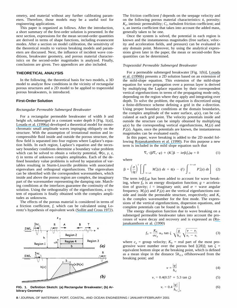
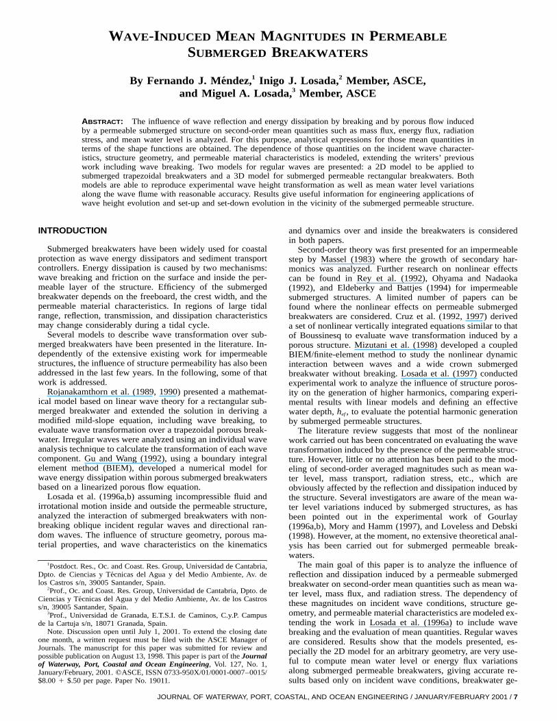
FIG. 1. Definition Sketch: (a) Rectangular Breakwater; (b) Ar-bitrary Geometry
ometry, and material without any further calibrating param-eters. Therefore, those models may be a useful tool forengineering applications.
This paper is organized as follows. After the introduction,a short summary of the first-order solution is presented. In thenext section, expressions for the mean second-order quantitiesare derived in terms of shape functions, including evanescentmodes. After a section on model calibration, the sensitivity ofthe theoretical results to various breaking models and param-eters are discussed. Next, the influence of incident wave con-ditions, breakwater geometry, and porous material character-istics on the second-order magnitudes is analyzed. Finally,conclusions are given. Two appendices are also included.
THEORETICAL ANALYSIS
In the following, the theoretical basis for two models, a 3Dmodel to analyze flow conditions in the vicinity of rectangularporous structures and a 2D model to be applied to trapezoidalporous breakwaters, is introduced.
First-Order Solution
Rectangular Permeable Submerged Breakwater
For a rectangular permeable breakwater of width b andheight ah, submerged in a constant water depth h [Fig. 1(a)],Losada et al. (1996a) developed a theoretical model for mono-chromatic small amplitude waves impinging obliquely on thestructure. With the assumption of irrotational motion and in-compressible fluid inside and outside the porous structure, theflow field is separated into four regions where Laplace’s equa-tion holds. In each region, Laplace’s equation and the neces-sary boundary conditions determine a boundary value problemwhich can be solved to obtain a velocity potential, F(x, y, z,t) in terms of unknown complex amplitudes. Each of the de-fined boundary value problems is solved by separation of var-iables resulting in Sturm-Liouville problems with associatedeigenvalues and orthogonal eigenfunctions. The eigenvaluescan be identified with the correspondent wavenumbers, whichinside and above the porous region are complex, the imaginarypart of the wavenumber representing the damping rate. Match-ing conditions at the interfaces guarantee the continuity of thesolution. Using the orthogonality of the eigenfunctions, a sys-tem of equations is finally obtained with the complex ampli-tudes as unknowns.
The effects of the porous material is considered in terms ofa friction coefficient, f, which can be calculated using Lo-rentz’s hypothesis of equivalent work (Sollitt and Cross 1972).
8 / JOURNAL OF WATERWAY, PORT, COASTAL, AND OCEAN ENGINEER
The friction coefficient f depends on the seepage velocity andon the following porous material characteristics: ε, porosity;Kp, intrinsic permeability; Cf , turbulent friction coefficient; ands, an inertia coefficient that takes into account the added mass,generally taken to be one.
Once the system is solved, the potential in each region isknown and the instantaneous magnitudes (free surface, veloc-ity and acceleration fields, and pressure) can be evaluated inany domain point. Moreover, by using the analytical expres-sions given later in the paper, the mean or second-order flowquantities can be determined.
Trapezoidal Permeable Submerged Breakwater
For a permeable submerged breakwater [Fig. 1(b)], Losadaet al. (1996b) presents a 2D solution based on an extension ofthe mild-slope equation. This extension of the mild-slopeequation for wave propagation over a porous layer is derivedby multiplying the Laplace equation by their correspondentvertical eigenfunctions in terms of the propagating mode only,depending on the region where they apply and integrating overdepth. To solve the problem, the equation is discretized usinga finite-difference scheme defining a grid in the x-direction.Using proper boundary conditions at the domain boundaries,the complex amplitude of the water surface, w(x), can be cal-culated at each grid point. The velocity potentials inside andoutside the structure can be simply obtained by multiplyingw(x) by the corresponding vertical eigenfunctions, Mo(z) andPo(z). Again, once the potentials are known, the instantaneousmagnitudes can be evaluated easily.
In this paper, wave breaking is added to the 2D model fol-lowing Rojanakamthorn et al. (1990). For this purpose a newterm is included in the mild slope equation such that
2= ? (b= ?w) 1 (K b 2 isb f )w = 0 (1)h h o D
where2 0 2h1ah
s 2 2b = M (z) dz 1 ε(s 2 if ) P (z) dz (2)o oS D FE E Gig 2h1ah 2h
The term isb fDw has been added to account for wave break-ing, where fD is an energy dissipation function; g = accelera-tion of gravity; i = imaginary unit; and s = wave angularfrequency. Mo(z) and Po(z) are the vertical eigenfunctions out-side and inside the permeable structure, respectively; and Ko
is the complex wavenumber for the first mode. The expres-sions of the vertical eigenfunctions, dispersion equations, andcomplete potentials can be found in Appendix I.
The energy dissipation function due to wave breaking on asubmerged permeable breakwater takes into account the pro-cesses of wave decay and recovery and is expressed as (Ro-janakamthorn et al. (1990)
K g n 2 nR rf = a tan z (3)D D Î Îsc h n 2 ng ef s r
where cg = group velocity; KR = real part of the most pro-gressive wave number over the porous bed [(28)]; tan z =equivalent bottom slope at the breaking point, which is definedas a mean slope in the distance 5hef ,b offshoreward from thebreaking point; and
uwun = (4)
hef
n = 0.4(0.57 1 5.3 tan z) (5)s
uwun = 0.4 (6)r Uhef bo
ING / JANUARY/FEBRUARY 2001
where the subscript b means the value at the breaking point.hef is the effective water depth over the porous layer (Losadaet al. 1997). This term can be calculated using (17). The pa-rameters ns and nr are expressed according to the results in thepaper of Watanabe and Dibajnia (1988). Therefore, althoughthe original value for aD is 2.5, a different aD has been foundin this work.
Instead of using the breaking criteria in Rojanakamthorn etal. (1990), the following formulation from Iwata and Kiyono(1985) for partial standing waves has been used to take intoaccount the reflection induced by the structure:
H 1 2 uR ub o= 0.218 2 0.076 tanh k h (7)b bF S DGL 1 1 uR ub o
where Hb = wave height at the breaking point; kb = 2p/Lb; Lb
= wave length at the breaking point; hb = water depth abovethe structure at the breaking point; and uRou = modulus of thereflection coefficient.
Once the breaking condition has been found, fD is calculatedusing the expression presented in Rojanakamthorn et al.(1990). In order to arrive at a solution, an iterative procedurehas to be carried out.
Mean Quantities
Once the first-order solution is known, mass flux, energyflux, and radiation stresses can be calculated. New expressionstaking into account the influence of wave reflection, transmis-sion, and dissipation are obtained.
These magnitudes of the mean quantities are formulated interms of shape functions (see Appendix II), which present theadvantage of allowing a more compact expression.
Mass Transport
The total mass flux in the x-direction, Mx, is given by
h
M = ru dz = ruhu (8)x z=0E0
In terms of the shape functions, the mass flux can be writtenas
1 2M = a r Re[H H*] (9)x h u U2 z=0
where (*) stands for complex conjugate; r = water density; a= incident wave amplitude; and Re[ ] stands for real part ofthe magnitude in brackets.
Radiation Stress
The presence of waves will result in an excess of momen-tum flux, which is defined as the radiation stress. The radiationstress will be affected by the presence of reflected waves andthe dissipation induced by breaking waves above the structureas well as by the flow through the porous material. The fourcomponents of the radiation tensor can be expressed in termsof the shape functions (Mei 1989) as
01 12 2 2 2 2 (4)S = a r(uH u 2 uH u )j(z) dz 1 rga uH u 1 S (10)xx u w hE2 42h
01 12 2 2 2 2 (4)S = a r(uH u 2 uH u )j(z) dz 1 rga uH u 1 S (11)yy n w hE2 42h
01 2S = a r Re[H H*]j(z) dz (12)xy u nE2 2h
In the fluid region, j(z) = 1, and in the porous region, j(z) is
JOURNAL OF WATERWAY, PORT, C
1 2h 1 ah < z < 0j(z) = (13)Hsε 2h < z < 2h 1 ah
S (4) is a term that takes into account the modulation of thewave field
0 01 (4) 2S = a r Re[H H*]j(z9) dz9u wE F SE D2 x2h z
0
1 r Re[H H*]j(z9) dz9 j(z) dzn wSE DGy z
This term can be neglected for progressive waves, but it mustbe included if there is wave energy reflection.
Energy Flux
The energy flux in the x-direction, ^x, is given by
0
^ = (p 1 rgz)u dz (14)x E2h
Based on the linearized Bernoulli equation in a fluid region,it can be obtained p 1 rgz = 2isrF. For a porous medium,the same equation (Sollitt and Cross 1972) yields p 1 rgz =2rsF(si 1 f ).
Therefore, for a porous layer of height ah, the energy flux,in terms of the shape functions, is defined as
2h1ah 01 12 2^ = a r Re[H H*]ε dz 1 a r Re[H H*] dzx u p u pE E2 22h 2h1ah
(15)
Expressions for other mean quantities including reflection anddissipation, such as set-down, impulse, mean pressure or kinetic,and potential mean energy can be found in Mendez (1997).
VALIDATION OF MODEL
Both models are validated using the experimental resultsdescribed in Rivero et al. (1998) and Tome (1997). The set ofexperimental tests was conducted at the large-scale wave flumeCIEM of LIM/UPC within the ‘‘Dynamics of Beaches’’ proj-ect. Free surface elevation and velocities were collected forregular and irregular waves at 12 stations in a 100 m long and3 m wide flume for a submerged breakwater on a 1:15 rigidsloping bottom. The submerged breakwater, with 1:1.5 slopeson both sides, has a crown width of 0.61 m and is constructedof an impermeable core and an armor layer of quarrystoneswith a mean weight of 25 Kg. The water depth at the toe ofthe structure was 1.50 m.
The first order has been solved using (1) including wavebreaking. The numerical boundary condition at the end of theflume has been modified to include the reflection induced bythe concrete sloping bottom. The result is given in terms ofthe wave height envelope along the flume. To solve the prob-lem, it is necessary to specify the mechanic characteristics ofthe permeable material, ε, Kp, Cf, and s. These magnitudeshave been calculated using the empirical expressions in vanGent (1995), which are based on the material D50, and theresulting values are ε = 0.4, Kp = 2.5 ?1025 m2, Cf = 0.32, ands = 1.0. These characteristics are independent of the flow andare therefore kept constant for all the cases considered in theexperimental work.
The mean water level variation is solved using the time-averaged and depth-integrated momentum equation
S hxx = 2rg(h 1 h) (16)x x
where Sxx is expressed as in (10).
OASTAL, AND OCEAN ENGINEERING / JANUARY/FEBRUARY 2001 / 9
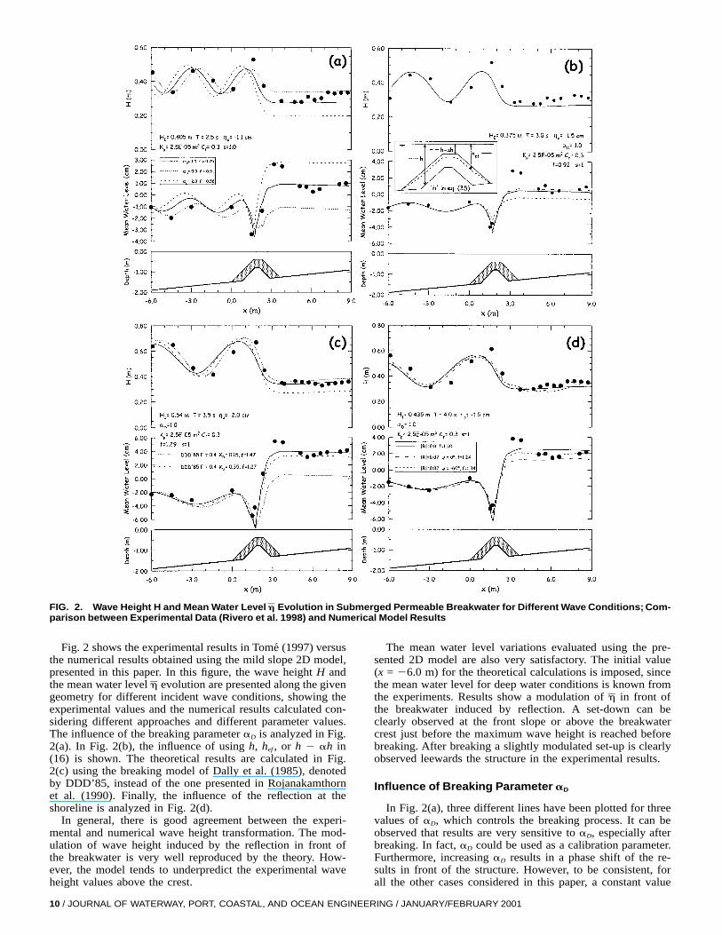
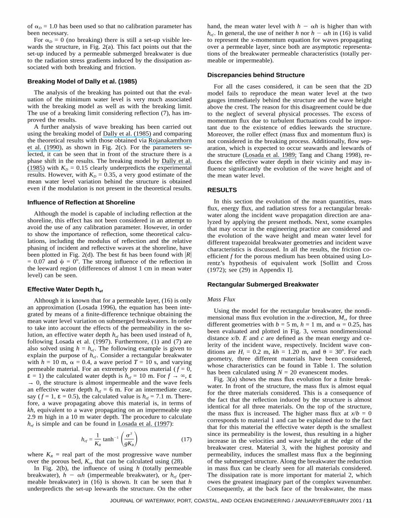
FIG. 2. Wave Height H and Mean Water Level Evolution in Submerged Permeable Breakwater for Different Wave Conditions; Com-hparison between Experimental Data (Rivero et al. 1998) and Numerical Model Results
Fig. 2 shows the experimental results in Tome (1997) versusthe numerical results obtained using the mild slope 2D model,presented in this paper. In this figure, the wave height H andthe mean water level evolution are presented along the givenhgeometry for different incident wave conditions, showing theexperimental values and the numerical results calculated con-sidering different approaches and different parameter values.The influence of the breaking parameter aD is analyzed in Fig.2(a). In Fig. 2(b), the influence of using h, hef , or h 2 ah in(16) is shown. The theoretical results are calculated in Fig.2(c) using the breaking model of Dally et al. (1985), denotedby DDD’85, instead of the one presented in Rojanakamthornet al. (1990). Finally, the influence of the reflection at theshoreline is analyzed in Fig. 2(d).
In general, there is good agreement between the experi-mental and numerical wave height transformation. The mod-ulation of wave height induced by the reflection in front ofthe breakwater is very well reproduced by the theory. How-ever, the model tends to underpredict the experimental waveheight values above the crest.
10 / JOURNAL OF WATERWAY, PORT, COASTAL, AND OCEAN ENGINE
The mean water level variations evaluated using the pre-sented 2D model are also very satisfactory. The initial value(x = 26.0 m) for the theoretical calculations is imposed, sincethe mean water level for deep water conditions is known fromthe experiments. Results show a modulation of in front ofhthe breakwater induced by reflection. A set-down can beclearly observed at the front slope or above the breakwatercrest just before the maximum wave height is reached beforebreaking. After breaking a slightly modulated set-up is clearlyobserved leewards the structure in the experimental results.
Influence of Breaking Parameter aD
In Fig. 2(a), three different lines have been plotted for threevalues of aD, which controls the breaking process. It can beobserved that results are very sensitive to aD, especially afterbreaking. In fact, aD could be used as a calibration parameter.Furthermore, increasing aD results in a phase shift of the re-sults in front of the structure. However, to be consistent, forall the other cases considered in this paper, a constant value
ERING / JANUARY/FEBRUARY 2001
of aD = 1.0 has been used so that no calibration parameter hasbeen necessary.
For aD = 0 (no breaking) there is still a set-up visible lee-wards the structure, in Fig. 2(a). This fact points out that theset-up induced by a permeable submerged breakwater is dueto the radiation stress gradients induced by the dissipation as-sociated with both breaking and friction.
Breaking Model of Dally et al. (1985)
The analysis of the breaking has pointed out that the eval-uation of the minimum water level is very much associatedwith the breaking model as well as with the breaking limit.The use of a breaking limit considering reflection (7), has im-proved the results.
A further analysis of wave breaking has been carried outusing the breaking model of Dally et al. (1985) and comparingthe theoretical results with those obtained via Rojanakamthornet al. (1990), as shown in Fig. 2(c). For the parameters se-lected, it can be seen that in front of the structure there is aphase shift in the results. The breaking model by Dally et al.(1985) with KD = 0.15 clearly underpredicts the experimentalresults. However, with KD = 0.35, a very good estimate of themean water level variation behind the structure is obtainedeven if the modulation is not present in the theoretical results.
Influence of Reflection at Shoreline
Although the model is capable of including reflection at theshoreline, this effect has not been considered in an attempt toavoid the use of any calibration parameter. However, in orderto show the importance of reflection, some theoretical calcu-lations, including the modulus of reflection and the relativephasing of incident and reflective waves at the shoreline, havebeen plotted in Fig. 2(d). The best fit has been found with uRu= 0.07 and c = 07. The strong influence of the reflection inthe leeward region (differences of almost 1 cm in mean waterlevel) can be seen.
Effective Water Depth hef
Although it is known that for a permeable layer, (16) is onlyan approximation (Losada 1996), the equation has been inte-grated by means of a finite-difference technique obtaining themean water level variation on submerged breakwaters. In orderto take into account the effects of the permeability in the so-lution, an effective water depth hef has been used instead of h,following Losada et al. (1997). Furthermore, (1) and (7) arealso solved using h = hef . The following example is given toexplain the purpose of hef . Consider a rectangular breakwaterwith h = 10 m, a = 0.4, a wave period T = 10 s, and varyingpermeable material. For an extremely porous material ( f = 0,ε = 1) the calculated water depth is hef = 10 m. For f → `, ε→ 0, the structure is almost impermeable and the wave feelsan effective water depth hef = 6 m. For an intermediate case,say ( f = 1, ε = 0.5), the calculated value is hef = 7.1 m. There-fore, a wave propagating above this material is, in terms ofkh, equivalent to a wave propagating on an impermeable step2.9 m high in a 10 m water depth. The procedure to calculatehef is simple and can be found in Losada et al. (1997):
21 s21h = tanh (17)ef S DK gKR R
where KR = real part of the most progressive wave numberover the porous bed, Ko, that can be calculated using (28).
In Fig. 2(b), the influence of using h (totally permeablebreakwater), h 2 ah (impermeable breakwater), or hef (per-meable breakwater) in (16) is shown. It can be seen that hunderpredicts the set-up leewards the structure. On the other
JOURNAL OF WATERWAY, PORT, CO
hand, the mean water level with h 2 ah is higher than withhef . In general, the use of neither h nor h 2 ah in (16) is validto represent the x-momentum equation for waves propagatingover a permeable layer, since both are asymptotic representa-tions of the breakwater permeable characteristics (totally per-meable or impermeable).
Discrepancies behind Structure
For all the cases considered, it can be seen that the 2Dmodel fails to reproduce the mean water level at the twogauges immediately behind the structure and the wave heightabove the crest. The reason for this disagreement could be dueto the neglect of several physical processes. The excess ofmomentum flux due to turbulent fluctuations could be impor-tant due to the existence of eddies leewards the structure.Moreover, the roller effect (mass flux and momentum flux) isnot considered in the breaking process. Additionally, flow sep-aration, which is expected to occur seawards and leewards ofthe structure (Losada et al. 1989; Tang and Chang 1998), re-duces the effective water depth in their vicinity and may in-fluence significantly the evolution of the wave height and ofthe mean water level.
RESULTS
In this section the evolution of the mean quantities, massflux, energy flux, and radiation stress for a rectangular break-water along the incident wave propagation direction are ana-lyzed by applying the present methods. Next, some examplesthat may occur in the engineering practice are considered andthe evolution of the wave height and mean water level fordifferent trapezoidal breakwater geometries and incident wavecharacteristics is discussed. In all the results, the friction co-efficient f for the porous medium has been obtained using Lo-rentz’s hypothesis of equivalent work [Sollitt and Cross(1972); see (29) in Appendix I].
Rectangular Submerged Breakwater
Mass Flux
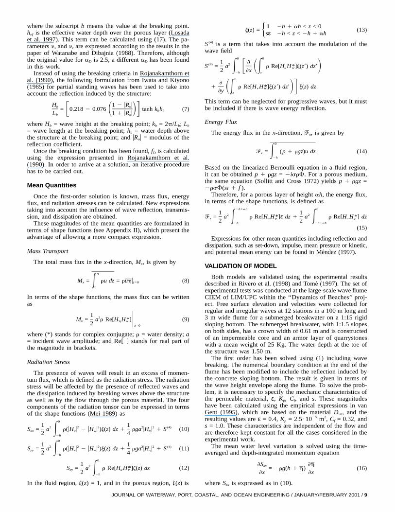
Using the model for the rectangular breakwater, the nondi-mensional mass flux evolution in the x-direction, Mx, for threedifferent geometries with b = 5 m, h = 1 m, and a = 0.25, hasbeen evaluated and plotted in Fig. 3, versus nondimensionaldistance x/b. E and c are defined as the mean energy and ce-lerity of the incident wave, respectively. Incident wave con-ditions are Hi = 0.2 m, kh = 1.20 m, and u = 307. For eachgeometry, three different materials have been considered,whose characteristics can be found in Table 1. The solutionhas been calculated using N = 20 evanescent modes.
Fig. 3(a) shows the mass flux evolution for a finite break-water. In front of the structure, the mass flux is almost equalfor the three materials considered. This is a consequence ofthe fact that the reflection induced by the structure is almostidentical for all three materials. On the top of the structure,the mass flux is increased. The higher mass flux at x/b = 0corresponds to material 1 and can be explained due to the factthat for this material the effective water depth is the smallestsince its permeability is the lowest, thus resulting in a higherincrease in the velocities and wave height at the edge of thebreakwater crest. Material 3, with the highest porosity andpermeability, induces the smallest mass flux a the beginningof the submerged structure. Along the breakwater the reductionin mass flux can be clearly seen for all materials considered.The dissipation rate is more important for material 2, whichowes the greatest imaginary part of the complex wavenumber.Consequently, at the back face of the breakwater, the mass
ASTAL, AND OCEAN ENGINEERING / JANUARY/FEBRUARY 2001 / 11
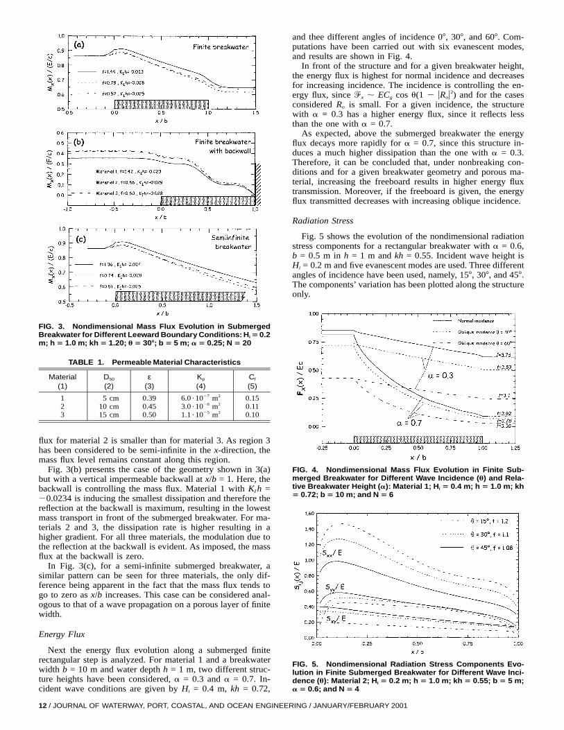
FIG. 3. Nondimensional Mass Flux Evolution in SubmergedBreakwater for Different Leeward Boundary Conditions: Hi 5 0.2m; h 5 1.0 m; kh 5 1.20; u 5 308; b 5 5 m; a 5 0.25; N 5 20
TABLE 1. Permeable Material Characteristics
Material(1)
D50
(2)ε
(3)Kp
(4)Cf
(5)
1 5 cm 0.39 6.0 ?1027 m2 0.152 10 cm 0.45 3.0 ?1026 m2 0.113 15 cm 0.50 1.1 ?1025 m2 0.10
flux for material 2 is smaller than for material 3. As region 3has been considered to be semi-infinite in the x-direction, themass flux level remains constant along this region.
Fig. 3(b) presents the case of the geometry shown in 3(a)but with a vertical impermeable backwall at x/b = 1. Here, thebackwall is controlling the mass flux. Material 1 with KI h =20.0234 is inducing the smallest dissipation and therefore thereflection at the backwall is maximum, resulting in the lowestmass transport in front of the submerged breakwater. For ma-terials 2 and 3, the dissipation rate is higher resulting in ahigher gradient. For all three materials, the modulation due tothe reflection at the backwall is evident. As imposed, the massflux at the backwall is zero.
In Fig. 3(c), for a semi-infinite submerged breakwater, asimilar pattern can be seen for three materials, the only dif-ference being apparent in the fact that the mass flux tends togo to zero as x/b increases. This case can be considered anal-ogous to that of a wave propagation on a porous layer of finitewidth.
Energy Flux
Next the energy flux evolution along a submerged finiterectangular step is analyzed. For material 1 and a breakwaterwidth b = 10 m and water depth h = 1 m, two different struc-ture heights have been considered, a = 0.3 and a = 0.7. In-cident wave conditions are given by Hi = 0.4 m, kh = 0.72,
12 / JOURNAL OF WATERWAY, PORT, COASTAL, AND OCEAN ENGIN
FIG. 5. Nondimensional Radiation Stress Components Evo-lution in Finite Submerged Breakwater for Different Wave Inci-dence (u): Material 2; Hi 5 0.2 m; h 5 1.0 m; kh 5 0.55; b 5 5 m;a 5 0.6; and N 5 4
FIG. 4. Nondimensional Mass Flux Evolution in Finite Sub-merged Breakwater for Different Wave Incidence (u) and Rela-tive Breakwater Height (a): Material 1; Hi 5 0.4 m; h 5 1.0 m; kh5 0.72; b 5 10 m; and N 5 6
and thee different angles of incidence 07, 307, and 607. Com-putations have been carried out with six evanescent modes,and results are shown in Fig. 4.
In front of the structure and for a given breakwater height,the energy flux is highest for normal incidence and decreasesfor increasing incidence. The incidence is controlling the en-ergy flux, since ^x ; ECg cos u(1 2 uRou2) and for the casesconsidered Ro is small. For a given incidence, the structurewith a = 0.3 has a higher energy flux, since it reflects lessthan the one with a = 0.7.
As expected, above the submerged breakwater the energyflux decays more rapidly for a = 0.7, since this structure in-duces a much higher dissipation than the one with a = 0.3.Therefore, it can be concluded that, under nonbreaking con-ditions and for a given breakwater geometry and porous ma-terial, increasing the freeboard results in higher energy fluxtransmission. Moreover, if the freeboard is given, the energyflux transmitted decreases with increasing oblique incidence.
Radiation Stress
Fig. 5 shows the evolution of the nondimensional radiationstress components for a rectangular breakwater with a = 0.6,b = 0.5 m in h = 1 m and kh = 0.55. Incident wave height isHi = 0.2 m and five evanescent modes are used. Three differentangles of incidence have been used, namely, 157, 307, and 457.The components’ variation has been plotted along the structureonly.
EERING / JANUARY/FEBRUARY 2001
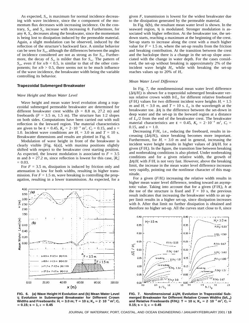
FIG. 6. (a) Wave Height H Evolution and (b) Mean Water LevelEvolution in Submerged Breakwater for Different Crownh
Widths and Freeboards: Hi 5 3.0 m; T 5 10 s; Kp 5 2 ?1024 m2; Cf
5 0.15; s 5 1, « 5 0.45
As expected, Sxx is maximum for normal incidence decreas-ing with wave incidence, since the x component of the mo-mentum flux decreases with increasing incidence. On the con-trary, Sxy and Syy increase with increasing u. Furthermore, forany u, Sxx decreases along the breakwater, since the momentumis being lost to dissipation induced by the permeable material.Again, a slight modulation can be observed, induced by thereflection of the structure’s backward face. A similar behaviorcan be seen for Sxy, although the differences between the anglesof incidence considered are not as strong as for Sxx. Further-more, the decay of Sxy is milder than for Sxx. The pattern ofSyy, even if for x/b < 0.5, is similar to that of the other com-ponents; for x/b > 0.5, there seems not to be much influenceof the wave incidence, the breakwater width being the variablecontrolling its behavior.
Trapezoidal Submerged Breakwater
Wave Height and Mean Water Level
Wave height and mean water level evolution along a trap-ezoidal submerged permeable breakwater are determined fordifferent breakwater crest widths (b = 8.8 m, 27.2 m) andfreeboards (F = 3.5 m, 1.5 m). The structure has 1:2 slopeson both sides. Computations have been carried out with nullreflection in the leeward region. The material characteristicsare given to be ε = 0.45, Kp = 2?1024 m2, Cf = 0.15, and s =1.0. Incident wave conditions are Hi = 3.0 m and T = 10 s.Breakwater dimensions and results are plotted in Fig. 6.
Modulation of wave height in front of the breakwater isclearly visible [Fig. 6(a)], with maxima positions slightlyshifted with respect to the breakwater crest starting position.As expected, the lowest modulation is associated to F = 3.5m and b = 27.2 m, since reflection is lowest for this case, uRou= 0.03.
For F = 3.5 m, dissipation is induced by friction only andattenuation is low for both widths, resulting in higher trans-mission. For F = 1.5 m, wave breaking is controlling the prop-agation, resulting in a lower transmission. As expected, for a
JOURNAL OF WATERWAY, PORT, C
FIG. 7. Nondimensional Evolution in Trapezoidal Sub-Dh/Hi
merged Breakwater for Different Relative Crown Widths (b/L p)and Relative Freeboards (F/Hi): T 5 10 s; Kp 5 2 ?1024 m2; Cf 50.15; s 5 1; « 5 0.45
given F, transmission is lowest for the widest breakwater dueto the dissipation generated by the permeable material.
In Fig. 6(b), the resultant mean water level is shown. In theseaward region, is modulated. Stronger modulation is as-hsociated with higher reflection. At the breakwater toe, the set-down starts, reaching a maximum at the beginning of the crest.Set-up starts to increase along the crest with a much highervalue for F = 1.5 m, where the set-up results from the frictionand breaking contribution. At the transition between the crestand the backslope there is a change in the set-up slope asso-ciated with the change in water depth. For the cases consid-ered, the set-up without breaking is approximately 2% of theincident wave height Hi, while with breaking the set-upreaches values up to 20% of Hi.
Mean Water Level Difference
In Fig. 7, the nondimensional mean water level differenceis shown for a trapezoidal submerged breakwater ver-(Dh/H )i
sus relative crown width b/Lp for different relative freeboard(F/Hi) values for two different incident wave heights Hi = 1.5m and Hi = 3.0 m, and T = 10 s. Lp is the wavelength at thebreakwater toe. is the difference between the set-down inDhdeep water and the set-up in the leeward region at a distanceof Lp/2 from the end of the breakwater crest. The breakwatermaterial characteristics are ε = 0.45, Kp = 2 ?1024 m2, Cf =0.15, and s = 1.0.
Decreasing F/Hi, i.e., reducing the freeboard, results in in-creasing since breaking becomes more important.(Dh/H ),i
Furthermore, for Hi = 3.0 m and in general, increasing theincident wave height results in higher values of for aDh/Hi
given (F/Hi). In the figure, the transition line between breakingand nonbreaking conditions is also plotted. Under nonbreakingconditions and for a given relative width, the growth of
with F/Hi is not very fast. However, above the breakingDh/Hi
limit, the increase in the mean water level difference increasesvery rapidly, pointing out the nonlinear character of this mag-nitude.
For a given (F/Hi) increasing the relative width results inhigher mean water level difference, tending toward an asymp-totic value. Taking into account that for a given (F/Hi), h atthe toe of the structure is fixed and T = 10 s, the previousresult indicates that increasing the breakwater width to an up-per limit results in a higher set-up, since dissipation increaseswith b. After that limit no further dissipation is obtained andtherefore no higher set-up. All the curves start close to 0, since
OASTAL, AND OCEAN ENGINEERING / JANUARY/FEBRUARY 2001 / 13
b/Lp → 0 implies no breakwater and therefore no dissipation.For F/Hi = 0.33 and close to b/Lp = 0.25, there is a resonantcondition, giving a maximum mean water level difference.
Under nonbreaking conditions and for Hi = 1.5 m, variesDhbetween 1 and 10% of the incident wave height and reachesup to 25% of Hi under breaking conditions. For Hi = 3 m, thepercentage can reach 35%.
CONCLUSIONS
In this paper two models, a 3D model for permeable rec-tangular breakwaters and a 2D model for permeable break-waters of arbitrary geometry, are presented to evaluate second-order magnitudes. The 2D model includes wave breakingconsidering different breaking models, and once the incidentwave conditions, breakwater geometry, the porosity, and theD50 of the porous material are known, the model is capable ofcalculating the second-order magnitudes evolution without anyfurther calibrations. Both models are able to reproduce waveheight transformation as well as mean water level variationsalong the breakwater with reasonable accuracy.
In front of the structure, second-order magnitudes are mod-ulated due to the reflection induced by the structure. Undernonbreaking conditions, second-order magnitudes are attenu-ated. The dissipation rate is dependent upon wave conditions,breakwater geometry, and porous material characteristics. Un-der nonbreaking conditions and for a given breakwater ge-ometry and porous material, increasing the freeboard yieldshigher energy flux transmission. Furthermore, for a given free-board, the energy flux transmitted decreases with increasingoblique incidence. These conclusions are important especiallyfor the design of beach toe protection structures, providing themodels a tool to evaluate the energy flux transmitted.
Results point out that the set-up induced by a permeablesubmerged breakwater is due to the radiation stress gradientsinduced by the dissipation associated with both breaking andfriction. The set-up due to breaking is much more importantthan the one due to dissipation induced by the porous material.For the cases considered, the set-up without breaking is ap-proximately 2–5% of the incident wave height Hi, while withbreaking the set-up reaches values up to 20% of Hi, or evenhigher. These values are highly dependent on wave height.
The mean water level variations show a modulation in frontof the structure, a maximum set-down at the beginning of thecrest, and a progressive increase along the crest reaching itsmaximum value approximately at the backslope. Roller ef-fects, flow separation, and turbulent effects should be furtherexplored.
APPENDIX I. FIRST-ORDER SOLUTION
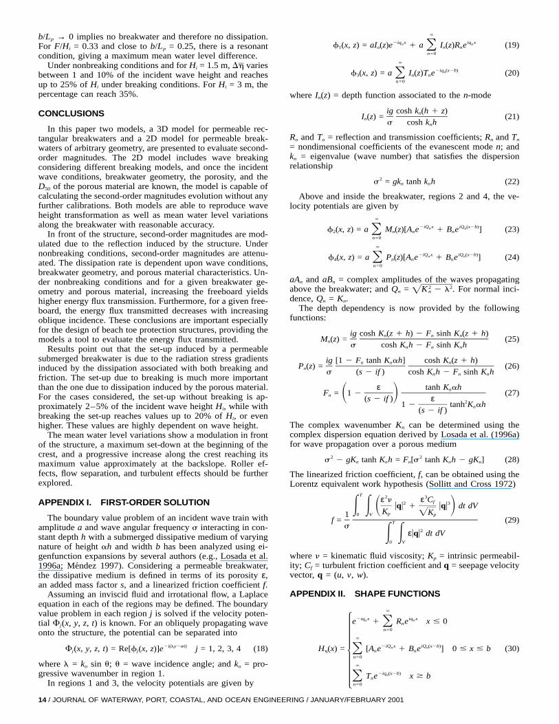
The boundary value problem of an incident wave train withamplitude a and wave angular frequency s interacting in con-stant depth h with a submerged dissipative medium of varyingnature of height ah and width b has been analyzed using ei-genfunction expansions by several authors (e.g., Losada et al.1996a; Mendez 1997). Considering a permeable breakwater,the dissipative medium is defined in terms of its porosity ε,an added mass factor s, and a linearized friction coefficient f.
Assuming an inviscid fluid and irrotational flow, a Laplaceequation in each of the regions may be defined. The boundaryvalue problem in each region j is solved if the velocity poten-tial Fj(x, y, z, t) is known. For an obliquely propagating waveonto the structure, the potential can be separated into
2i(ly2st)F (x, y, z, t) = Re[f (x, z)]e j = 1, 2, 3, 4 (18)j j
where l = ko sin u; u = wave incidence angle; and ko = pro-gressive wavenumber in region 1.
In regions 1 and 3, the velocity potentials are given by
14 / JOURNAL OF WATERWAY, PORT, COASTAL, AND OCEAN ENGINE
`
2iq x iq xo nf (x, z) = aI (z)e 1 a I (z)R e (19)1 o n nOn=0
`
2iq (x2b)nf (x, z) = a I (z)T e (20)3 n nOn=0
where In(z) = depth function associated to the n-mode
ig cosh k (h 1 z)nI (z) = (21)n
s cosh k hn
Ro and To = reflection and transmission coefficients; Rn and Tn
= nondimensional coefficients of the evanescent mode n; andkn = eigenvalue (wave number) that satisfies the dispersionrelationship
2s = gk tanh k h (22)n n
Above and inside the breakwater, regions 2 and 4, the ve-locity potentials are given by
`
2iQ x iQ (x2b)n nf (x, z) = a M (z)[A e 1 B e ] (23)2 n n nOn=0
`
2iQ x iQ (x2b)n nf (x, z) = a P (z)[A e 1 B e ] (24)4 n n nOn=0
aAn and aBn = complex amplitudes of the waves propagatingabove the breakwater; and Qn = For normal inci-2 2K 2 l .nÏdence, Qn = Kn.
The depth dependency is now provided by the followingfunctions:
ig cosh K (z 1 h) 2 F sinh K (z 1 h)n n nM (z) = (25)n
s cosh K h 2 F sinh K hn n n
ig [1 2 F tanh K ah] cosh K (z 1 h)n n nP (z) = (26)n
s (s 2 if ) cosh K h 2 F sinh K hn n n
ε tanh K ahnF = 1 2 (27)n S D(s 2 if ) ε 21 2 tanh K ahn(s 2 if )
The complex wavenumber Kn can be determined using thecomplex dispersion equation derived by Losada et al. (1996a)for wave propagation over a porous medium
2 2s 2 gK tanh K h = F [s tanh K h 2 gK ] (28)n n n n n
The linearized friction coefficient, f, can be obtained using theLorentz equivalent work hypothesis (Sollitt and Cross 1972)
T 2 3ε n ε Cf2 3uqu 1 uqu dt dVE E S DK Kp Ï0 V p1f = (29)Ts
2εuqu dt dVE E0 V
where n = kinematic fluid viscosity; Kp = intrinsic permeabil-ity; Cf = turbulent friction coefficient and q = seepage velocityvector, q = (u, v, w).
APPENDIX II. SHAPE FUNCTIONS
`
2iq x iq xo ne 1 R e x # 0nOn=0
`
2iQ x iQ (x2b)n nH (x) = [A e 1 B e ] 0 # x # b (30)h n nOn=0
`
2iq (x2b)nT e x $ bnOn=0
ERING / JANUARY/FEBRUARY 2001
for a rectangular submerged breakwater; and Hh(x) = (1/a)w(x)for a submerged breakwater of arbitrary geometry:
(H (x, z), H (x, z), H (x, z))u v w
1 f(x, z) il 1 f(x, z)= , 2 f(x, z),S Da x a a z (31)
is2 f(x, z) fluid region
aH (x, z) = (32)p H (si 1 f )s
2 f(x, z) porous regiona
where f(x, z) has been defined in Appendix I for rectangularbreakwaters. For submerged breakwaters of arbitrary geome-try, f(x, z) is
M (z)w(x) 2h 1 ah # z # 0of(x, z) = (33)H
P (z)w(x) 2h # z # 2h 1 aho
ACKNOWLEDGMENTS
The writers acknowledge the funding provided by Spanish ComisionInterministerial de Ciencia y Technologıa (CICYT) under contractsMAR96-1833 and MAR99-0653.
APPENDIX III. REFERENCES
Cruz, E. C., Isobe, M., and Watanabe, A. (1992). ‘‘Nonlinear wave trans-formation over a submerged permeable breakwater.’’ Proc., 23rd Coast.Engrg. Conf., ASCE, New York, 1101–1114.
Cruz, E. C., Isobe, M., and Watanabe, A. (1997). ‘‘Boussinesq equationsfor wave transformation on porous beds.’’ Coast. Engrg., 30, 125–154.
Dally, W. R., Dean, R. G., and Dalrymple, R. A. (1985). ‘‘Wave heightvariation across beaches of arbitrary profile.’’ J. Geophys. Res., 90(C6),11917–11927.
Dalrymple, R. A., Losada, M. A., and Martin, P. (1991). ‘‘Reflection andtransmission from porous structures under oblique wave attack.’’ J.Fluid Mech., 224, 625–644.
Eldeberky, Y., and Battjes, J. A. (1994). ‘‘Nonlinear coupling in wavespropagating over a bar.’’ Proc., 24th Coast. Engrg. Conf., ASCE, NewYork, 157–167.
Gourlay, M. R. (1996a). ‘‘Wave set-up on coral reefs. I: Set-up and wave-generated flow on an idealised two dimensional horizontal reef.’’ Coast.Engrg., 27, 161–193.
Gourlay, M. R. (1996b). ‘‘Wave set-up on coral reefs. II: Wave set-up onreefs with various profiles.’’ Coast. Engrg., 28, 17–56.
Gu, Z. G., and Wang, H. (1992). ‘‘Numerical modeling for wave energydissipation within porous submerged breakwaters of irregular cross sec-tion.’’ Proc., 23rd Coast. Engrg. Conf., ASCE, New York, 1189–1202.
Iwata, K., and Kiyono, H. (1985). ‘‘Breaking of standing two-componentcomposite and irregular waves.’’ Coast. Engrg. in Japan, Tokyo, 28,71–87.
Losada, I. J. (1996). ‘‘Wave interaction with permeable structures.’’ PhDthesis, University of Delaware, Newark, Del.
JOURNAL OF WATERWAY, PORT, CO
Losada, I. J., Silva, R., and Losada, M. A. (1996a). ‘‘3-D non-breakingregular wave interaction with submerged breakwaters.’’ Coast. Engrg.,28, 229–248.
Losada, I. J., Silva, R., and Losada, M. A. (1996b). ‘‘Interaction of non-breaking directional random waves with submerged breakwaters.’’Coast. Engrg., 28, 249–267.
Losada, I. J., Patterson, M. D., and Losada, M. A. (1997). ‘‘Harmonicgeneration past a submerged porous step.’’ Coast. Engrg., 31, 281–304.
Losada, M. A., Vidal, C., and Medina, R. (1989). ‘‘Experimental studyof the evolution of a solitary wave at an abrupt junction.’’ J. Geophys.Res., 94(C10), 14557–14566.
Loveless, J., and Debski, D. (1998). ‘‘Sea level set-up behind detachedbreakwaters.’’ Proc., 26th Coast. Engrg. Conf., ASCE, Reston, Va.,1665–1678.
Massel, S. R. (1983). ‘‘Harmonic generation by waves propagating overa submerged step.’’ Coast. Engrg., 7, 357–380.
Mei, C. C. (1989). The applied dynamics of ocean surface waves, WorldScientific, Singapore.
Mendez, F. J. (1997). ‘‘Flujos medios inducidos por las ondas de gravedaden medios reflejantes y disipativos naturales o artificiales.’’ PhD thesis,University of Cantabria, Cantabria, Spain (in Spanish).
Mizutani, N., Mostafa, A. M., and Iwata, K. (1998). ‘‘Nonlinear regularwave, submerged breakwater and seabed dynamic interaction.’’ Coast.Engrg., 33, 177–202.
Mory, M., and Hamm, L. (1997). ‘‘Wave height, set-up and currentsaround a detached breakwater submitted to regular or random waveforcing.’’ Coast. Engrg., 31, 77–96.
Ohyama, T., and Nadaoka, K. (1992). ‘‘Modelling of the transformationof nonlinear waves passing over a submerged dike.’’ Proc., 23rd Coast.Engrg. Conf., ASCE, New York, 526–539.
Rey, V., Belzons, M., and Guazzelli, E. (1992). ‘‘Propagation of surfacegravity waves over a rectangular submerged bar.’’ J. Fluid Mech., 235,453–479.
Rivero, F. J., S.-Arcilla, A., Gironella, X., and Corrons, A. (1998).‘‘Large-scale hydrodynamic experiments in submerged breakwaters.’’Proc., Coast. Dyn. ’97, ASCE, Reston, Va., 754–762.
Rojanakamthorn, S., Isobe, M., and Watanabe, A. (1989). ‘‘A mathemat-ical model of wave transformation over a submerged breakwater.’’Coast. Engrg. in Japan, Tokyo, 32(2), 209–234.
Rojanakamthorn, S., Isobe, M., and Watanabe, A. (1990). ‘‘Modeling ofwave transformation on submerged breakwater.’’ Proc., 22nd Coast.Engrg. Conf., ASCE, New York, 1060–1073.
Sollitt, C. K., and Cross, R. H. (1972). ‘‘Wave transmission through per-meable breakwaters.’’ Proc., 13th Coast. Engrg. Conf., ASCE, NewYork, 1827–1846.
Tang, C. J., and Chang, J. H. (1998). ‘‘Flow separation during solitarywave passing over submerged obstacle.’’ J. Hydr. Engrg., ASCE,124(7), 742–749.
Tome, M. (1997). ‘‘Modelado matematico de la circulacion 2DH inducidapor el oleaje en presencia de diques sumergidos.’’ MS thesis, UPC (inSpanish).
van Gent, M. R. A. (1995). ‘‘Wave interaction with permeable coastalstructures.’’ PhD thesis, Delft University of Technology, Delft, TheNetherlands.
Watanabe, A., and Dibajnia, M. (1988). ‘‘A numerical model of wavedeformation in surf zone.’’ Proc., 21st Coast. Engrg. Conf., ASCE, NewYork, 578–587.
ASTAL, AND OCEAN ENGINEERING / JANUARY/FEBRUARY 2001 / 15