performance of concrete armour units of breakwaters in india
TRANSCRIPT
https://iaeme.com/Home/issue/IJCIET 54 [email protected]
International Journal of Civil Engineering and Technology (IJCIET)
Volume 12, Issue 6, June 2021, pp. 54-66, Article ID: IJCIET_12_06_005
Available online at https://iaeme.com/Home/issue/IJCIET?Volume=12&Issue=6
ISSN Print: 0976-6308 and ISSN Online: 0976-6316
DOI: 10.34218/IJCIET.12.6.2021.005
© IAEME Publication
PERFORMANCE OF CONCRETE ARMOUR
UNITS OF BREAKWATERS IN INDIA
- A REVIEW
Apurva M. Kudale
Assistant Professor, Department of Civil Engineering,
Vishwakarma Institute of Information Technology, Pune, India
M. D. Kudale
Assistant Professor, Department of Civil Engineering, Vishwakarma Institute of Information
Technology, Pune, & Former Additional Director, Central Water and Power Research Station,
Pune, India
Dr. P. B. Kulkarni
Professor, Department of Civil Engineering,
Vishwakarma Institute of Information Technology, Pune, India
ABSTRACT
Most of the breakwaters of the major, intermediate and minor ports as well as
fishing harbours in India are constructed as flexible rubblemound structures, armoured
with quarry stones or artificial concrete armour units. Tetrapods, Dolosse and Cubes
are common concrete armour units, which are to be used in double layer in the armour
of the rubblemound structures. Development of deep water ports in India has
necessitated the designs involving lesser costs. In this context, use of single layer
armour units on steeper slopes is inevitable. Single layer armour units like Accropode
and Core-loc have also been used for a few breakwaters. Tetrapods are more popular
in India in comparison with other armour units. Rubblemound breakwaters constructed
in India, using artificial concrete armour units have stood well against the fury of waves.
However, there are few examples of damages to the breakwaters during the severe
cyclonic wave conditions. The design aspects, site conditions, constraints, and the
performance of artificial concrete units have been discussed in the paper. It is observed
that selection of design wave condition, packing density, placing method, slope, and
proper toe-berm are important aspects in the design and construction of rubblemound
breakwaters with artificial concrete armour units.
Keywords: Harbour, Breakwater, Rubblemound, Armour Units, Design Wave,
Tetrapods, Accropode, Dolos
Performance of Concrete Armour Units of Breakwaters in India - A Review
https://iaeme.com/Home/issue/IJCIET 55 [email protected]
Cite this Article: Apurva M. Kudale, M.D. Kudale, and P. B. Kulkarni, Performance
of Concrete Armour Units of Breakwaters in India - A Review, International Journal
of Civil Engineering and Technology (IJCIET), 12(6), 2021, pp. 54-66.
https://iaeme.com/Home/issue/IJCIET?Volume=12&Issue=6
1. INTRODUCTION
Breakwaters are the structures constructed to protect coastal harbour facilities from the hostile
forces of ocean waves and to provide tranquil conditions for the berthing operations of ships.
Various types of breakwater structures are rigid, semi-rigid and flexible. Flexible rubblemound
structures are commonly used for breakwater construction. A breakwater built as a
rubblemound structure is constructed by placing stones of various sizes, layer by layer,
comprising a bedding layer, core, secondary layer protected by an armour layer and a toe to
prevent slippage of armour units. Armour layer of rubblemound breakwater consists of selected
units of quarry stones, if available in the required size and quantity; otherwise, specially
designed concrete armour units are used. Better interlocking property of the artificial concrete
armour units makes it possible to use armour units lighter than the required quarry stones.
The stability of the rubblemound under wave attack is important aspect in the design of
rubblemound breakwaters. The other aspects of the effect of waves on rubblemound are wave
run-up, overtopping, reflection and transmission. The stability of rubblemound breakwaters
depends primarily upon the stability of individual armour units on its seaward slope. As such,
a major aspect in the design is the optimum weight of the armour units on the seaward slope,
required to withstand the design waves. Studies have been reported on the hydraulic stability
of individual armour units on the seaward slope and empirical formulae are available for the
estimation of the optimum weight (Shore Protection Manual, SPM, 1984) [1]. The present
design practices of rubblemound breakwaters and seawalls are based on hydraulic model tests
in wave flumes to confirm the conceptual design.
A variety of shapes of the concrete armour units have been used in the seaward armour
layers of the rubblemound breakwaters. A few of them are Cubes, Tetrapods, Tribars, Hexapod,
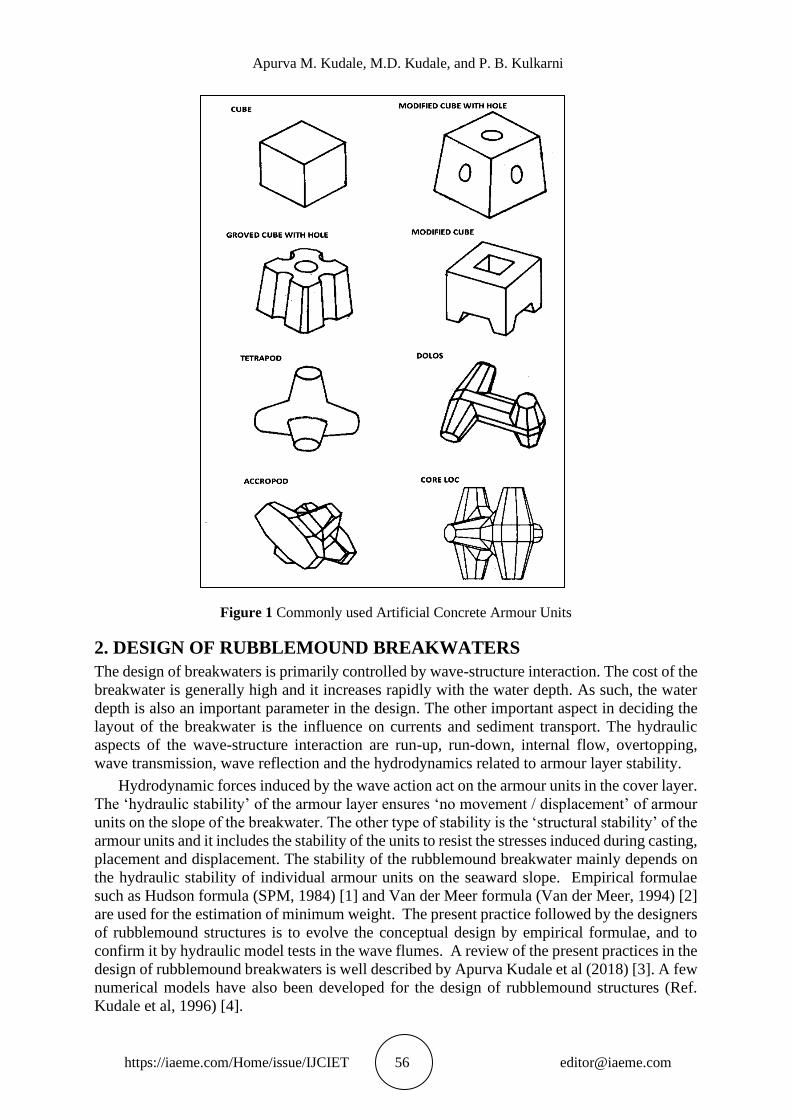
Akmon, Stabit, Dolosse etc. Typical artificial concrete armour units are shown in Fig. 1. More
recently developed blocks are Accropode, Core-loc and X-Blocks. The hydraulic stability of
armour units on the seaward face of the breakwaters to withstand design wave conditions not
only depends on its weight, but also upon shape, interlocking, specific weight, slope of the
structure, number of layers, method of placement, packing density, location (trunk or
roundhead), type of waves (breaking or non-breaking) etc. The “Stability Coefficient” (KD),
claimed by the Inventors of different types of armour blocks, which depend on these factors,
has been always a controversial issue. As such, hydraulic stability tests in the model either in a
2-D wave flume or a 3-D wave basin become inevitable for the design of the rubblemound
structures in which site-specific conditions are correctly simulated.
In India, rubblemound breakwaters have been adopted for the most of the major and minor
ports. Quarry stones / rocks as well as artificial concrete blocks such as Tetrapods, Dolosse and
Cubes are common armour units used in India for the rubblemound breakwaters and seawalls.
These concrete units are to be used in double layer in the armour. Development of deep-water
ports in India has necessitated the designs involving lesser costs. As such, single layer armour
units like Accropode and Core-loc have also been used for a few breakwaters. Tetrapods are
more popular in India in comparison with the other armour units. Rubblemound breakwaters
constructed using artificial concrete armour units have stood well against the fury of waves.
However, there are few examples of damages to the breakwaters during the severe cyclonic
wave conditions. The design aspects, site conditions, constraints, and the performance of
artificial concrete units have been discussed in the paper.
Apurva M. Kudale, M.D. Kudale, and P. B. Kulkarni
https://iaeme.com/Home/issue/IJCIET 56 [email protected]
Figure 1 Commonly used Artificial Concrete Armour Units
2. DESIGN OF RUBBLEMOUND BREAKWATERS
The design of breakwaters is primarily controlled by wave-structure interaction. The cost of the
breakwater is generally high and it increases rapidly with the water depth. As such, the water
depth is also an important parameter in the design. The other important aspect in deciding the
layout of the breakwater is the influence on currents and sediment transport. The hydraulic
aspects of the wave-structure interaction are run-up, run-down, internal flow, overtopping,
wave transmission, wave reflection and the hydrodynamics related to armour layer stability.
Hydrodynamic forces induced by the wave action act on the armour units in the cover layer.
The ‘hydraulic stability’ of the armour layer ensures ‘no movement / displacement’ of armour
units on the slope of the breakwater. The other type of stability is the ‘structural stability’ of the
armour units and it includes the stability of the units to resist the stresses induced during casting,
placement and displacement. The stability of the rubblemound breakwater mainly depends on
the hydraulic stability of individual armour units on the seaward slope. Empirical formulae
such as Hudson formula (SPM, 1984) [1] and Van der Meer formula (Van der Meer, 1994) [2]
are used for the estimation of minimum weight. The present practice followed by the designers
of rubblemound structures is to evolve the conceptual design by empirical formulae, and to
confirm it by hydraulic model tests in the wave flumes. A review of the present practices in the
design of rubblemound breakwaters is well described by Apurva Kudale et al (2018) [3]. A few
numerical models have also been developed for the design of rubblemound structures (Ref.
Kudale et al, 1996) [4].
Performance of Concrete Armour Units of Breakwaters in India - A Review
https://iaeme.com/Home/issue/IJCIET 57 [email protected]
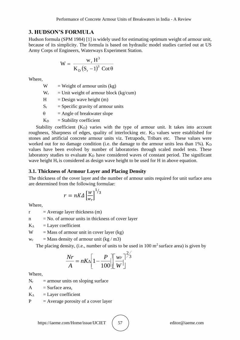
3. HUDSON’S FORMULA
Hudson formula (SPM 1984) [1] is widely used for estimating optimum weight of armour unit,
because of its simplicity. The formula is based on hydraulic model studies carried out at US
Army Corps of Engineers, Waterways Experiment Station.
Where,
W = Weight of armour units (kg)
Wr = Unit weight of armour block (kg/cum)
H = Design wave height (m)
Sr = Specific gravity of armour units
= Angle of breakwater slope
KD = Stability coefficient
Stability coefficient (KD) varies with the type of armour unit. It takes into account
roughness, Sharpness of edges, quality of interlocking etc. KD values were established for
stones and artificial concrete armour units viz. Tetrapods, Tribars etc. These values were
worked out for no damage condition (i.e. the damage to the armour units less than 1%). KD
values have been evolved by number of laboratories through scaled model tests. These
laboratory studies to evaluate KD have considered waves of constant period. The significant
wave height Hs is considered as design wave height to be used for H in above equation.
3.1. Thickness of Armour Layer and Placing Density
The thickness of the cover layer and the number of armour units required for unit surface area
are determined from the following formulae:
𝑟 = 𝑛𝐾𝛥 [𝑊
𝑤𝑟]13⁄
Where,
r = Average layer thickness (m)
n = No. of armour units in thickness of cover layer
KΔ = Layer coefficient
W = Mass of armour unit in cover layer (kg)
wr = Mass density of armour unit (kg / m3)
The placing density, (i.e., number of units to be used in 100 m2 surface area) is given by
32
1001
−=
W
wPnK
A
Nr r
Where,
Nr = armour units on sloping surface
A = Surface area,
KΔ = Layer coefficient
P = Average porosity of a cover layer
( ) θCot1SK
HwW
3
rD
3r
−=
Apurva M. Kudale, M.D. Kudale, and P. B. Kulkarni
https://iaeme.com/Home/issue/IJCIET 58 [email protected]
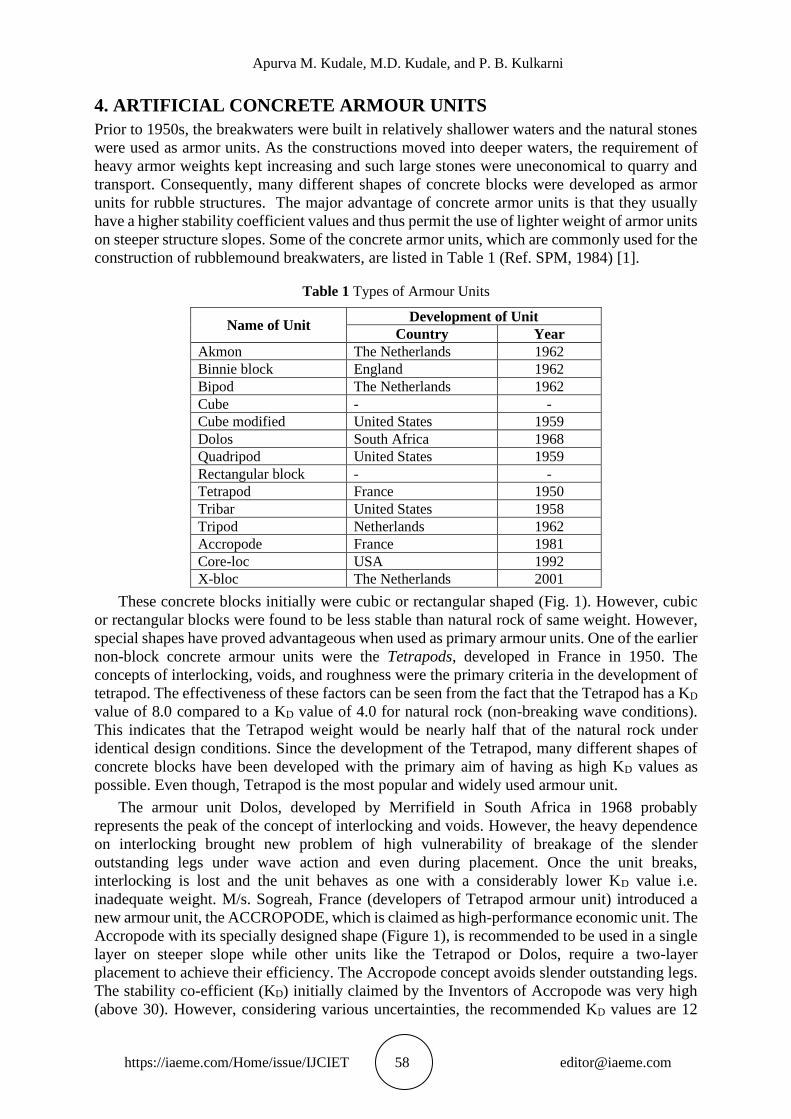
4. ARTIFICIAL CONCRETE ARMOUR UNITS
Prior to 1950s, the breakwaters were built in relatively shallower waters and the natural stones
were used as armor units. As the constructions moved into deeper waters, the requirement of
heavy armor weights kept increasing and such large stones were uneconomical to quarry and
transport. Consequently, many different shapes of concrete blocks were developed as armor
units for rubble structures. The major advantage of concrete armor units is that they usually
have a higher stability coefficient values and thus permit the use of lighter weight of armor units
on steeper structure slopes. Some of the concrete armor units, which are commonly used for the
construction of rubblemound breakwaters, are listed in Table 1 (Ref. SPM, 1984) [1].
Table 1 Types of Armour Units
Name of Unit Development of Unit
Country Year
Akmon The Netherlands 1962
Binnie block England 1962
Bipod The Netherlands 1962
Cube - -
Cube modified United States 1959
Dolos South Africa 1968
Quadripod United States 1959
Rectangular block - -
Tetrapod France 1950
Tribar United States 1958
Tripod Netherlands 1962
Accropode France 1981
Core-loc USA 1992
X-bloc The Netherlands 2001
These concrete blocks initially were cubic or rectangular shaped (Fig. 1). However, cubic
or rectangular blocks were found to be less stable than natural rock of same weight. However,
special shapes have proved advantageous when used as primary armour units. One of the earlier
non-block concrete armour units were the Tetrapods, developed in France in 1950. The
concepts of interlocking, voids, and roughness were the primary criteria in the development of
tetrapod. The effectiveness of these factors can be seen from the fact that the Tetrapod has a KD
value of 8.0 compared to a KD value of 4.0 for natural rock (non-breaking wave conditions).
This indicates that the Tetrapod weight would be nearly half that of the natural rock under
identical design conditions. Since the development of the Tetrapod, many different shapes of
concrete blocks have been developed with the primary aim of having as high KD values as
possible. Even though, Tetrapod is the most popular and widely used armour unit.
The armour unit Dolos, developed by Merrifield in South Africa in 1968 probably
represents the peak of the concept of interlocking and voids. However, the heavy dependence
on interlocking brought new problem of high vulnerability of breakage of the slender
outstanding legs under wave action and even during placement. Once the unit breaks,
interlocking is lost and the unit behaves as one with a considerably lower KD value i.e.
inadequate weight. M/s. Sogreah, France (developers of Tetrapod armour unit) introduced a
new armour unit, the ACCROPODE, which is claimed as high-performance economic unit. The
Accropode with its specially designed shape (Figure 1), is recommended to be used in a single
layer on steeper slope while other units like the Tetrapod or Dolos, require a two-layer
placement to achieve their efficiency. The Accropode concept avoids slender outstanding legs.
The stability co-efficient (KD) initially claimed by the Inventors of Accropode was very high
(above 30). However, considering various uncertainties, the recommended KD values are 12
Performance of Concrete Armour Units of Breakwaters in India - A Review
https://iaeme.com/Home/issue/IJCIET 59 [email protected]
and 15 for breaking and non-breaking wave conditions. WES, USA in 1992 has introduced the
concrete armour unit called ‘Core-loc’. The Core-locs are similar to the Accropodes and are to
be laid in a single layer. The stability claimed for Core-loc is higher than that for the Accropode.
The stability of artificial armour blocks Tetrapod, Dolos and Accropode has been assessed
under random sea wave conditions (Gadre et al, 1991) [5], (Vaidyaraman et al, 1995) [6]. The
equivalent design wave height taken in the design formula for representing the random wave
train was the significant wave height (HS). However, the studies by Kudale et al (2015) [7]
revealed that this equivalent design wave height shall be H1/10 (average of highest one-tenth of
the waves) instead of HS. The studies on Dolos armour units with different packing densities
(i.e., number of units per 100m2 surface area) indicated that the lower packing density as well
as higher packing density affects adversely on the stability of armour layer (Gadre et a., 1986)
[8]. The importance of simulating exact seabed slope in front of the model of rubblemound
structure in the wave flume was enumerated, by assessing the stability of armour stones with
different seabed slopes (Sarma and Kudale, 2011) [9].
5. INDIAN SCENARIO
As stated earlier, most of the breakwaters constructed for various Indian Ports are rubblemound
structures with natural stones or Tetrapods in the armour. At some places concrete cubes and
Dolosse have also been used. More recently, single layer armour units viz. Accropode and Core-
Loc are also utilized at few harbours (Kudale et al, 2018) [10].
Some of the breakwaters, and their performance is discussed in the succeeding paragraphs.
5.1. Breakwaters at Visakhapatnam Port
Visakhapatnam Port was commissioned in 1976 and consists of the Inner and Outer Harbour.
The Outer Harbour is formed by construction of three breakwaters viz. South breakwater, North
Breakwater, and East Breakwater. Large concrete cubes have been used in the armour of the
main breakwaters. These cubes are having holes to release the wave energy as well as to
facilitate lifting and placing of blocks. The south breakwater lies in the water depth of about 17
m and was designed to withstand the waves of the order of 7 m in height. The weight of the
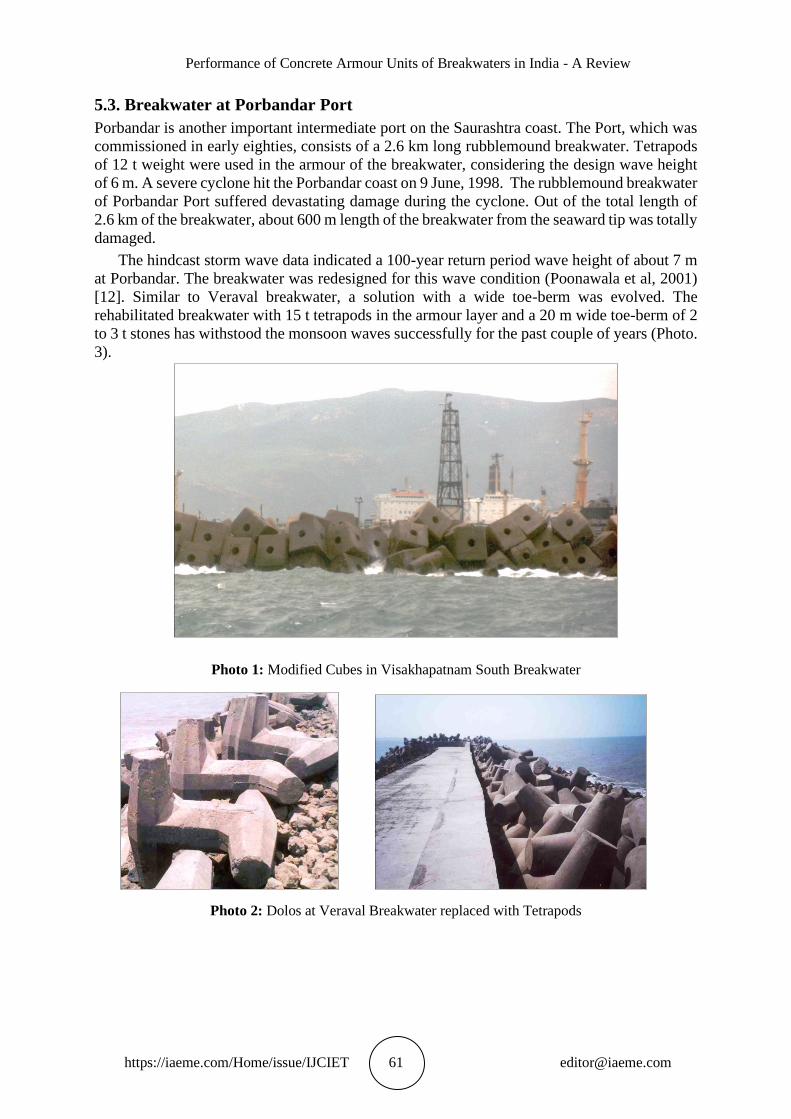
concrete cubes is about 50 tonne and these blocks were provided on seaside slope, crest, and
the leeside slope of the breakwater (Photo. 1). The roundhead of the south breakwater consists
of 35 tonne Dolosse units in the armour.
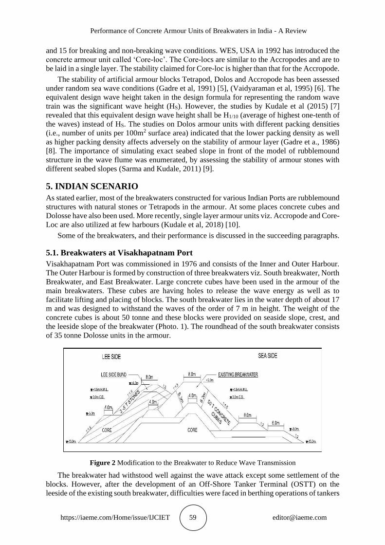
Figure 2 Modification to the Breakwater to Reduce Wave Transmission
The breakwater had withstood well against the wave attack except some settlement of the
blocks. However, after the development of an Off-Shore Tanker Terminal (OSTT) on the
leeside of the existing south breakwater, difficulties were faced in berthing operations of tankers
Apurva M. Kudale, M.D. Kudale, and P. B. Kulkarni
https://iaeme.com/Home/issue/IJCIET 60 [email protected]
at the OSTT due to wave disturbance. The root cause of the disturbance was the transmission
of the waves through the breakwater because of the voids in the large armour units. A rubble
apron was provided on the leeside of the breakwater (Fig. 2) based on the hydraulic model
studies in the wave flume (Poonawala et al, 2001) [11], which has successfully reduced wave
disturbance in front of the OST Terminal on the leeside.
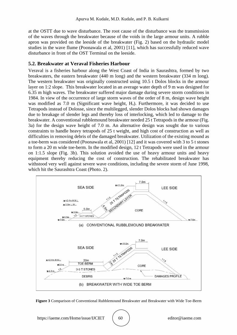
5.2. Breakwater at Veraval Fisheries Harbour
Veraval is a fisheries harbour along the West Coast of India in Saurashtra, formed by two
breakwaters, the eastern breakwater (440 m long) and the western breakwater (334 m long).
The western breakwater was originally constructed using 10.5 t Dolos blocks in the armour
layer on 1:2 slope. This breakwater located in an average water depth of 9 m was designed for
6.35 m high waves. The breakwater suffered major damage during severe storm conditions in
1984. In view of the occurrence of large storm waves of the order of 8 m, design wave height
was modified as 7.0 m (Significant wave height, Hs). Furthermore, it was decided to use
Tetrapods instead of Dolosse, since the multilegged, slender Dolos blocks had shown damages
due to breakage of slender legs and thereby loss of interlocking, which led to damage to the
breakwater. A conventional rubblemound breakwater needed 25 t Tetrapods in the armour (Fig.
3a) for the design wave height of 7.0 m. An alternative design was sought due to various
constraints to handle heavy tetrapods of 25 t weight, and high cost of construction as well as
difficulties in removing debris of the damaged breakwater. Utilization of the existing mound as
a toe-berm was considered (Poonawala et al, 2001) [12] and it was covered with 3 to 5 t stones
to form a 20 m wide toe-berm. In the modified design, 12 t Tetrapods were used in the armour
on 1:1.5 slope (Fig. 3b). This solution avoided the use of heavy armour units and heavy
equipment thereby reducing the cost of construction. The rehabilitated breakwater has
withstood very well against severe wave conditions, including the severe storm of June 1998,
which hit the Saurashtra Coast (Photo. 2).
Figure 3 Comparison of Conventional Rubblemound Breakwater and Breakwater with Wide Toe-Berm
Performance of Concrete Armour Units of Breakwaters in India - A Review
https://iaeme.com/Home/issue/IJCIET 61 [email protected]
5.3. Breakwater at Porbandar Port
Porbandar is another important intermediate port on the Saurashtra coast. The Port, which was
commissioned in early eighties, consists of a 2.6 km long rubblemound breakwater. Tetrapods
of 12 t weight were used in the armour of the breakwater, considering the design wave height
of 6 m. A severe cyclone hit the Porbandar coast on 9 June, 1998. The rubblemound breakwater
of Porbandar Port suffered devastating damage during the cyclone. Out of the total length of
2.6 km of the breakwater, about 600 m length of the breakwater from the seaward tip was totally
damaged.
The hindcast storm wave data indicated a 100-year return period wave height of about 7 m
at Porbandar. The breakwater was redesigned for this wave condition (Poonawala et al, 2001)
[12]. Similar to Veraval breakwater, a solution with a wide toe-berm was evolved. The
rehabilitated breakwater with 15 t tetrapods in the armour layer and a 20 m wide toe-berm of 2
to 3 t stones has withstood the monsoon waves successfully for the past couple of years (Photo.
3).
Photo 1: Modified Cubes in Visakhapatnam South Breakwater
Photo 2: Dolos at Veraval Breakwater replaced with Tetrapods
Apurva M. Kudale, M.D. Kudale, and P. B. Kulkarni
https://iaeme.com/Home/issue/IJCIET 62 [email protected]
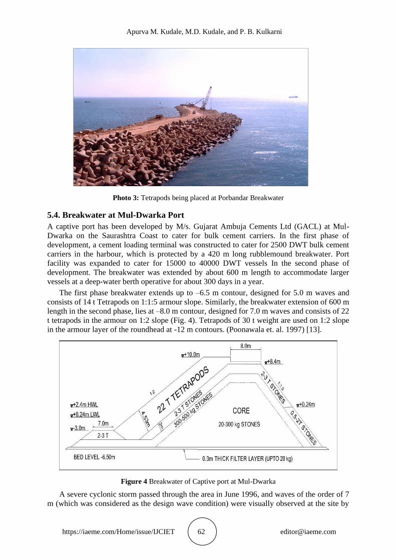
Photo 3: Tetrapods being placed at Porbandar Breakwater
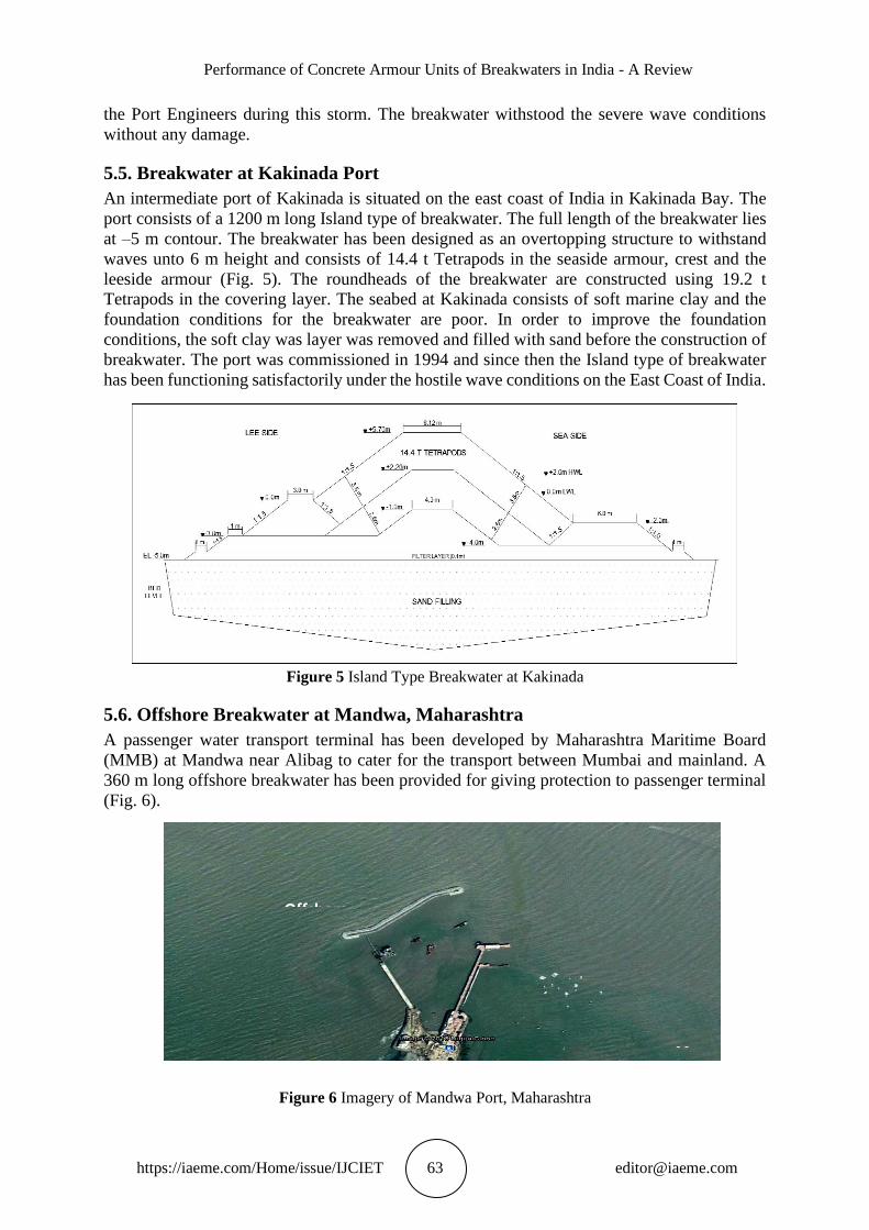
5.4. Breakwater at Mul-Dwarka Port
A captive port has been developed by M/s. Gujarat Ambuja Cements Ltd (GACL) at Mul-
Dwarka on the Saurashtra Coast to cater for bulk cement carriers. In the first phase of
development, a cement loading terminal was constructed to cater for 2500 DWT bulk cement
carriers in the harbour, which is protected by a 420 m long rubblemound breakwater. Port
facility was expanded to cater for 15000 to 40000 DWT vessels In the second phase of
development. The breakwater was extended by about 600 m length to accommodate larger
vessels at a deep-water berth operative for about 300 days in a year.
The first phase breakwater extends up to –6.5 m contour, designed for 5.0 m waves and
consists of 14 t Tetrapods on 1:1:5 armour slope. Similarly, the breakwater extension of 600 m
length in the second phase, lies at –8.0 m contour, designed for 7.0 m waves and consists of 22
t tetrapods in the armour on 1:2 slope (Fig. 4). Tetrapods of 30 t weight are used on 1:2 slope
in the armour layer of the roundhead at -12 m contours. (Poonawala et. al. 1997) [13].
Figure 4 Breakwater of Captive port at Mul-Dwarka
A severe cyclonic storm passed through the area in June 1996, and waves of the order of 7
m (which was considered as the design wave condition) were visually observed at the site by
Performance of Concrete Armour Units of Breakwaters in India - A Review
https://iaeme.com/Home/issue/IJCIET 63 [email protected]
the Port Engineers during this storm. The breakwater withstood the severe wave conditions
without any damage.
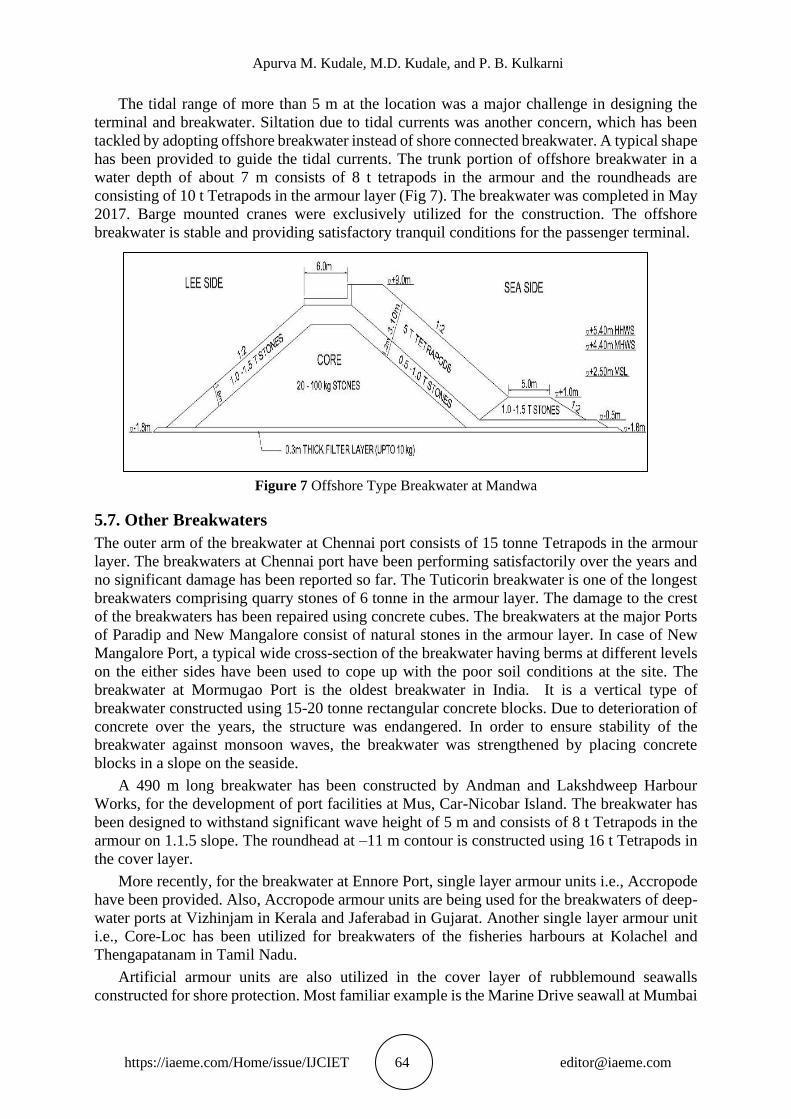
5.5. Breakwater at Kakinada Port
An intermediate port of Kakinada is situated on the east coast of India in Kakinada Bay. The
port consists of a 1200 m long Island type of breakwater. The full length of the breakwater lies
at –5 m contour. The breakwater has been designed as an overtopping structure to withstand
waves unto 6 m height and consists of 14.4 t Tetrapods in the seaside armour, crest and the
leeside armour (Fig. 5). The roundheads of the breakwater are constructed using 19.2 t
Tetrapods in the covering layer. The seabed at Kakinada consists of soft marine clay and the
foundation conditions for the breakwater are poor. In order to improve the foundation
conditions, the soft clay was layer was removed and filled with sand before the construction of
breakwater. The port was commissioned in 1994 and since then the Island type of breakwater
has been functioning satisfactorily under the hostile wave conditions on the East Coast of India.
Figure 5 Island Type Breakwater at Kakinada
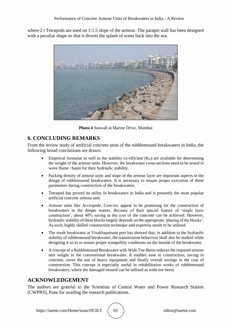
5.6. Offshore Breakwater at Mandwa, Maharashtra
A passenger water transport terminal has been developed by Maharashtra Maritime Board
(MMB) at Mandwa near Alibag to cater for the transport between Mumbai and mainland. A
360 m long offshore breakwater has been provided for giving protection to passenger terminal
(Fig. 6).
Figure 6 Imagery of Mandwa Port, Maharashtra
Offshore
May
Apurva M. Kudale, M.D. Kudale, and P. B. Kulkarni
https://iaeme.com/Home/issue/IJCIET 64 [email protected]
The tidal range of more than 5 m at the location was a major challenge in designing the
terminal and breakwater. Siltation due to tidal currents was another concern, which has been
tackled by adopting offshore breakwater instead of shore connected breakwater. A typical shape
has been provided to guide the tidal currents. The trunk portion of offshore breakwater in a
water depth of about 7 m consists of 8 t tetrapods in the armour and the roundheads are
consisting of 10 t Tetrapods in the armour layer (Fig 7). The breakwater was completed in May
2017. Barge mounted cranes were exclusively utilized for the construction. The offshore
breakwater is stable and providing satisfactory tranquil conditions for the passenger terminal.
Figure 7 Offshore Type Breakwater at Mandwa
5.7. Other Breakwaters
The outer arm of the breakwater at Chennai port consists of 15 tonne Tetrapods in the armour
layer. The breakwaters at Chennai port have been performing satisfactorily over the years and
no significant damage has been reported so far. The Tuticorin breakwater is one of the longest
breakwaters comprising quarry stones of 6 tonne in the armour layer. The damage to the crest
of the breakwaters has been repaired using concrete cubes. The breakwaters at the major Ports
of Paradip and New Mangalore consist of natural stones in the armour layer. In case of New
Mangalore Port, a typical wide cross-section of the breakwater having berms at different levels
on the either sides have been used to cope up with the poor soil conditions at the site. The
breakwater at Mormugao Port is the oldest breakwater in India. It is a vertical type of
breakwater constructed using 15-20 tonne rectangular concrete blocks. Due to deterioration of
concrete over the years, the structure was endangered. In order to ensure stability of the
breakwater against monsoon waves, the breakwater was strengthened by placing concrete
blocks in a slope on the seaside.
A 490 m long breakwater has been constructed by Andman and Lakshdweep Harbour
Works, for the development of port facilities at Mus, Car-Nicobar Island. The breakwater has
been designed to withstand significant wave height of 5 m and consists of 8 t Tetrapods in the
armour on 1.1.5 slope. The roundhead at –11 m contour is constructed using 16 t Tetrapods in
the cover layer.
More recently, for the breakwater at Ennore Port, single layer armour units i.e., Accropode
have been provided. Also, Accropode armour units are being used for the breakwaters of deep-
water ports at Vizhinjam in Kerala and Jaferabad in Gujarat. Another single layer armour unit
i.e., Core-Loc has been utilized for breakwaters of the fisheries harbours at Kolachel and
Thengapatanam in Tamil Nadu.
Artificial armour units are also utilized in the cover layer of rubblemound seawalls
constructed for shore protection. Most familiar example is the Marine Drive seawall at Mumbai
Performance of Concrete Armour Units of Breakwaters in India - A Review
https://iaeme.com/Home/issue/IJCIET 65 [email protected]
where 2 t Tetrapods are used on 1:1.5 slope of the armour. The parapet wall has been designed
with a peculiar shape so that it diverts the splash of water back into the sea.
Photo 4 Seawall at Marine Drive, Mumbai
6. CONCLUDING REMARKS
From the review study of artificial concrete units of the rubblemound breakwaters in India, the
following broad conclusions are drawn:
• Empirical formulae as well as the stability co-efficient (KD) are available for determining
the weight of the armour units. However, the breakwater cross-sections need to be tested in
wave flume / basin for their hydraulic stability.
• Packing density of armour units and slope of the armour layer are important aspects in the
design of rubblemound breakwaters. It is necessary to ensure proper execution of these
parameters during construction of the breakwaters.
• Tetrapod has proved its utility in breakwaters in India and is presently the most popular
artificial concrete armour unit.
• Armour units like Accropode, Core-loc appear to be promising for the construction of
breakwaters in the deeper waters. Because of their special feature of ‘single layer
construction’, about 40% saving in the cost of the concrete can be achieved. However,
hydraulic stability of these blocks largely depends on the appropriate ‘placing of the blocks’.
As such, highly skilled construction technique and expertise needs to be utilised.
• The south breakwater at Visakhapatnam port has showed that, in addition to the hydraulic
stability of rubblemound breakwater, the transmission behaviour shall also be studied while
designing it so as to ensure proper tranquillity conditions on the leeside of the breakwater.
• A concept of a Rubblemound Breakwater with Wide Toe-Berm reduces the required armour
unit weight in the conventional breakwater. It enables ease in construction, saving in
concrete, saves the use of heavy equipment and finally overall savings in the cost of
construction. This concept is especially useful in rehabilitation works of rubblemound
breakwaters, where the damaged mound can be utilised as wide toe-berm.
ACKNOWLEDGEMENT
The authors are grateful to the Scientists of Central Water and Power Research Station
(CWPRS), Pune for availing the research publications.
Apurva M. Kudale, M.D. Kudale, and P. B. Kulkarni
https://iaeme.com/Home/issue/IJCIET 66 [email protected]
REFERENCES
[1] Shore Protection Manual, (SPM), (1984), U.S. Army Corps of Engineers, Coastal Engineering
Centre, U.S. Government Printing Office, Washington D.C., U.S.A.
[2] Van der Meer J.W. (1988), "Rock Slopes and Gravel Beaches under Wave attack", Publication
No. 396, Delft Hydraulics, The Netherlands.
[3] Kudale Apurva M., Dr. Sohoni V. S., Dr. Patil B. M. and Mahalingaiah A. V. (2018), Present
Practices in Design of Rubblemound Breakwaters for Coastal Harbours – A Review”,
International Journal of Current Engineering and Technology (IJCET), Vol.8, No.3.
[4] Kudale M.D., Kobayashi N. (1996), "Hydraulic Stability Analysis of Leeside Slopes of
Overtopped Breakwaters", 25th Int. Conf. on Coastal Engineering, (ASCE), Orlando, Florida,
U.S.A.
[5] Gadre M.R., Poonawala I. Z. and Kudale M.D. (1991), "Stability of Tetrapods Under Random
Wave Attack", Third Int. Conf. on Coastal & Port Engineering in Developing Countries,
Mombasa, Kenya.
[6] Vaidyaraman P. P., Poonawala I. Z., Kudale M. D., Purohit A. A. (1995), “Stability of
Accropode Armour Units under Breaking Wave Conditions” Fourth International Conference
on Coastal and Port Engineering in Developing Countries, Rio de Janeiro, Brazil.
[7] Kudale M. D., Bhalerao A.R., (2015) “Equivalent Monochromatic Wave Height for the Design
of Coastal Rubblemound Structures” - Science Direct, Aquatic Procedia, ELSEVIER Journal
Publication, ISSN: 2214-241X, Volume 4 (2015), pp.264-273.
[8] Gadre M.R., Poonawala I.Z. and Kudale M.D. (1986), “Effect of Packing Density of Dolosse
on Stability of Armour Layer”, Third Indian Conference on Ocean Engineering, IIT, Bombay,
India.
[9] Sarma A.V. Sitarama, Kudale M.D. (2011), “Stability of wide toe berm breakwater with varying
seabed slope; Journal of Hydraulic Engineering, Indian Society for Hydraulics (ISH), Vol.17
No.2, pp. 43-49.
[10] M. D. Kudale, A. V. Mahalingaiah, B. R. Tayade (2018), “Rubblemound Breakwaters - Indian
Scenario”, - “Sixth National Conference on Coastal, Harbour and Ocean Engineering
(INCHOE-2108)”, CWPRS, Pune, India.
[11] Poonawala I.Z., Kudale M.D., Purohit A.A., Kulkarni S.P. and Das A. K. (2001), “Measures to
Reduce Wave Transmission through Rubblemound Breakwater – A Case Study”, International
Conference in Ocean Engineering, IIT, Madras, India.
[12] Poonawala I.Z., Kale A.G., Kudale M.D., Purohit A.A. and Das A. K. (2001) “A New concept
of Rubblemound Breakwaters with Wide Toe-Berm”, International Conference on Port and
Maritime R&D and Technology, Singapore.
[13] Poonawala I.Z., Kanetkar C. N., Kudale M. D., Vaidya A. M.(Mrs.) (1997) “Hydraulic Model
Studies for Captive Port at Mul-Dwarka - A Case Study", -; Second Indian National Conference
on Harbour and Ocean Engineering (INCHOE-1997), CESS, Thiruvananthapuram, India.