visual acuity testing of radiographic inspectors ... - govinfo.gov
TRANSCRIPT

z
V
coA
\
"^^j^
"*«?AU 0^
1.
CO NBS TECHNICAL NOTE1143
U.S. DEPARTMENT OF COMMERCE/ National Bureau of Standards
Visual Acuity Testing
of Radiographic Inspectors
in Nondestructive Inspection
QC
100
U5753
no. 1143
1981
c 2

NATIONAL BUREAU OF STANDARDS
The National Bureau of Standards' was established by an act of Congress on March 3, 1901.
The Bureau's overall goal is to strengthen and advance the Nation's science and technology
and facilitate their effective application for public benefit. To this end, the Bureau conducts
research and provides: (1) a basis for the Nation's physical measurement system, (2) scientific
and technological services for industry and government, (3) a technical basis for equity in
trade, and (4) technical services to promote public safety. The Bureau's technical work is per-
formed by the National Measurement Laboratory, the National Engineering Laboratory, and
the Institute for Computer Sciences and Technology.
THE NATIONAL MEASUREMENT LABORATORY provides the national system of
physical and chemical and materials measurement; coordinates the system with measurement
systems of other nations and furnishes essential services leading to accurate and uniform
physical and chemical measurement throughout the Nation's scientific community, industry,
and commerce; conducts materials research leading to improved methods of measurement,
standards, and data on the properties of materials needed by industry, commerce, educational
institutions, and Government; provides advisory and research services to other Government
agencies; develops, produces, and distributes Standard Reference Materials; and provides
calibration services. The Laboratory consists of the following centers:
Absolute Physical Quantities 2 — Radiation Research — Thermodynamics and
Molecular Science — Analytical Chemistry — Materials Science.
THE NATIONAL ENGINEERING LABORATORY provides technology and technical ser-
vices to the public and private sectors to address national needs and to solve national
problems; conducts research in engineering and applied science in support of these efforts;
builds and maintains competence in the necessary disciplines required to carry out this
research and technical service; develops engineering data and measurement capabilities;
provides engineering measurement traceability services; develops test methods and proposes
engineering standards and code changes; develops and proposes new engineering practices;
and develops and improves mechanisms to transfer results of its research to the ultimate user.
The Laboratory consists of the following centers:
Applied Mathematics — Electronics and Electrical Engineering 2 — Mechanical
Engineering and Process Technology 2 — Building Technology — Fire Research —Consumer Product Technology — Field Methods.
THE INSTITUTE FOR COMPUTER SCIENCES AND TECHNOLOGY conducts
research and provides scientific and technical services to aid Federal agencies in the selection,
acquisition, application, and use of computer technology to improve effectiveness and
economy in Government operations in accordance with Public Law 89-306 (40 U.S.C. 759),
relevant Executive Orders, and other directives; carries out this mission by managing the
Federal Information Processing Standards Program, developing Federal ADP standards
guidelines, and managing Federal participation in ADP voluntary standardization activities;
provides scientific and technological advisory services and assistance to Federal agencies; and
provides the technical foundation for computer-related policies of the Federal Government.
The Institute consists of the following centers:
Programming Science and Technology — Computer Systems Engineering.
'Headquarters and Laboratories at Gaithersburg, MD, unless otherwise noted;
mailing address Washington. DC 20234.2Some divisions within the center are located at Boulder, CO 80303.

NATIONAL BURBAOOr tftANDARDS
LIBRARY
Visual Acuity Testing ^
«
of Radiographic Inspectors
in Nondestructive Inspection
1981
Gary T. Yonemura
Center for Building Technology
National Engineering Laboratory
National Bureau of Standards
Washington, DC 20234
Prepared for:
Office of Nondestructive Evaluation
National Measurement Laboratory
National Bureau of Standards
Washington, DC 20234
<**T 0F o0t
U.S. DEPARTMENT OF COMMERCE, Malcolm Baldrige, Secretary
NATIONAL BUREAU OF STANDARDS, Ernest Ambler, Director
Issued June 1981

National Bureau of Standards Technical Note 1 143
Nat. Bur. Stand. (U.S.), Tech. Note 1 143, 29pages(June 1981)
CODEN: NBTNAE
U.S. GOVERNMENT PRINTING OFFICE
WASHINGTON: 1981
For sale by the Superintendent of Documents, U.S. Government Printing Office, Washington, D.C. 20402
Price $2.50
(Add 25 percent for other than U.S. mailing)

Visual Acuity Testing of Radiographic Inspectors inNondestructive Inspection
Gary T. YonemuraCenter for Building TechnologyNational Engineering Laboratory
National Bureau of StandardsU.S. Department of Commerce
Washington, DC 20234
Visual acuity tests for radiographic inspectorsshould be correlated with the type of tasksencountered in real world radiography. Thetesting procedures should be capable of
assessing differences in day to day performanceof a given inspector as well as the performanceof one inspector relative to other inspectors.Single line targets with specific parametricvalues for contrast, width, and blur arerecommended to provide a means for testing a
radiographic inspector for visual acuity.These targets may be used for periodic tests
by the employing organization or for morefrequent self testing by the inspector.Statistics from the National Health Survey,procedures recommended by the NAS-NRCCommittee on Vision and real world radiographshave been utilized in arriving at recommendedtest configurations
.
Key Words: Acuity tests; nondestructive testing; quality testing;radiograph evaluation; visual inspection; visual testing.
Disclaimer:
Certain trade names and company products are identified in order to
adequately specify the experimental procedure. In no case does suchidentification imply recommendation or endorsement by the NationalBureau of Standards, nor does it imply that the products arenecessarily the best available for the purpose.
111

Table of ContentsPage
1 . Introduction 1
1.
1
Visual Inspection 1
1.1.1 Detection 1
1.1.2 Interpretation 1
1.1.3 Evaluation 1
1.2 Scope 2
2 . Background 2
2 . 1 Variability 2
2.1.1 Intra (within) Observer Variability 2
2.1.2 Inter (between) Observer Variability 3
2
.
2 National Norm 3
3 . Reference Target Parameters 6
3.1 Size 6
3.1.1 Width of Target 8
3.1.2 Length of Target 8
3.2 Contrast 8
3
.
3 Blur 12
3 . 4 Form 12
3
.
5 Luminance - Density 15
3.6 Figure - Background Brightness Relationship 15
4 . Other Considerations 15
4. 1 Viewing Distance 15
4
.
2 Light Source 15
4.3 Test Room 16
4 . 4 Scoring 16
iv

5 . Recommendations 16
6 . References 22
v


1. Introduction
In assessing the acceptability of mensurative techniques, two basicuncertainty (reliability) measures are involved: the repeatability of
measurements with a given instrument and the agreement betweendifferent instruments or installations. Similar performance assess-ments leading to consistent performance should be required of visualinspections in nondestructive evaluation.
1.
1
Visual Inspection
The lack of precision in radiographic inspections has been discussedand documented in several studies.
-^ The sources of unreliabilityin radiographic inspections may be due to any of several causes,among them being differences in the components and procedures fortaking of the radiographs, and differences in visual capacity amongthe inspectors reading the radiographs. This paper shall be concernedwith the latter. By reliability, we mean the precision of inspections,that is, agreement between different observers within a unit, betweenunits within an installation, and between installations within anindustry as well as the repeatability (consistency) in the performanceof a given inspector. To achieve this end, procedures, apparatus,and reference materials should be standardized to minimize sources ofvariability.
In visual inspections, the human eye is the key component. Visualcapacity must therefore be calibrated and reference materials necessaryfor calibration must be available. The complete evaluation of the
inspector involves the calibration of the inspector's sensory capacityand the level of experience and knowledge that person brings to thetask.
1.1.1 Detection - The inspector must first detect the possiblepresence of a defect, generally indications of a discontinuity inthe radiograph. This resolution of a nonhomogeneity in the radio-graph is primarily dependent on the visual sensory capacity of theinspector, i.e., the psychophysiological capacity of the inspector.
1.1.2 Interpretation - Having detected the presence of a discon-tinuity, it is necessary to interpret this discontinuity to determinewhether it is a defect and, if so, to classify it as to the type of
defect.
1.1.3 Evaluation - The final inspection involves the determination ofthe magnitude and importance of the defect. Should the object berejected, repaired, or passed?

1. 2 Scope
All three of the above inspector performances involve visual sensorydiscrimination ability, the proportion of sensory involvement beingmaximal for detection but decreasing as we go from interpretation to
evaluation. As the role of sensory discrimination decreases, therole of information processing increases, i.e., the role of
experience and knowledge in interpreting the visual cues becomeimportance sources of differences in performance between observers.Inspectors can improve their knowledge by training, but visualcapacity, which includes corrective devices the inspector brings to
the job, is fixed. This report deals with visual acuity tests forradiographic inspectors that are simple to administer and usesstandardized procedures and reference tasks. It does not treat the
cognitive (experience) factors in visual inspection of radiographs,although a significant source of variability between inspectors may bethe lack of good training criteria.
2.0 Background
2.
1
Variability
Measurement variability may exist within an instrument and/or betweendifferent instruments. Within instrument variability is generallycalled precision or repeatability. Between instruments variability is
the agreement between different instruments, generally assessed bylaboratory intercomparisons of a reference material. We have thesesame sources of variability with visual inspection of radiographs.
2.1.1 Intra (within) Observer Variability -
Consistency or repeatability of measurements is of primary concern in
any mensurative technique, including measures relying on the perfor-mance of the human eye. Will the same inspector be able to detecttargets of the same difficulty equally often on different days?Psychophysical experiments indicate that even experienced observersdisplay variability in visual capacity that may vary from day to day.
These changes can be due to physiological or psychological factors. Insome cases performance at the prescribed level can be achieved by fol-lowing recommended procedures, for example, spending more time adaptingto the darkened environment of the inspection room.
For critical inspections or for the purposes of minimizing variability,a test is needed that inspectors can use for self calibration. Theycan then determine whether they are performing at a prescribed sensi-tivity level (or better) at the time that the test is taken.
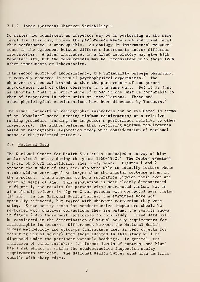
2.1.2 Inter (between) Observer Variability -
No matter how consistent an inspector may be in performing at the samelevel day after day, unless the performance meets some specified level,that performance is unacceptable. An analogy in instrumental measure-ments is the agreement between different instruments and/or differentlaboratories. A given instrument in a given laboratory may give highrepeatability, but the measurements may be inconsistent with those fromother instruments or laboratories.
This second source of inconsistency, the variability between observers,is commonly observed in visual psychophysical experiments. Theobserver must be calibrated so that the performance of one personapproximates that of other observers in the same unit. But it is justas important that the performance of those in one unit be comparable to
that of inspectors in other units or installations. These andother physiological considerations have been discussed by Yonemura.
The visual capacity of radiographic inspectors can be evaluated in terms
of an "absolute" score (meeting minimum requirements) or a relativeranking procedure (ranking the inspector's performance relative to other
inspectors) . The author believes that specifying minimum requirementsbased on radiographic inspection needs with consideration of nationalnorms is the preferred criteria.
2. 2 National Norm
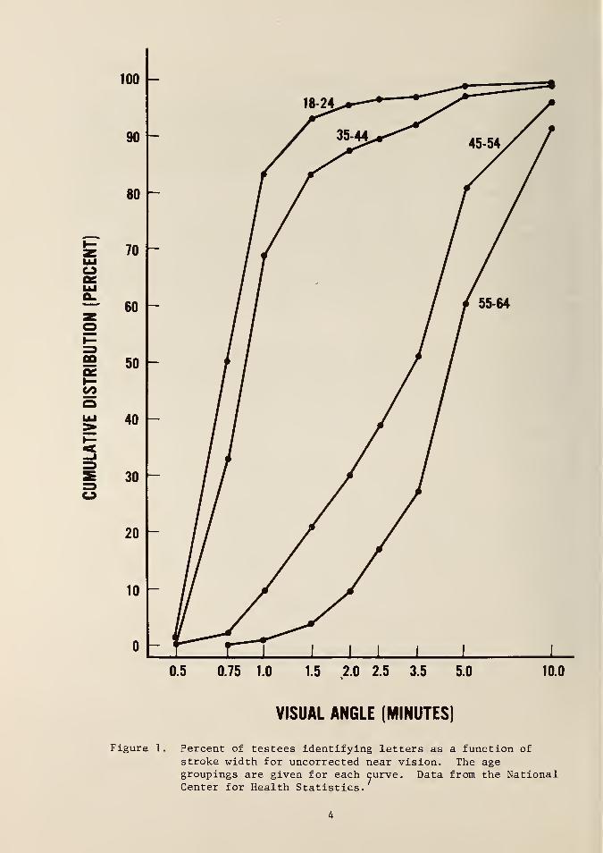
The National Center for Health Statistics conducted a survey of bin-ocular visual acuity during the years 1960-1962. The Center examineda total of 6,672 individuals, ages 18-79 years. Figures 1 and 2
present the number of examinees who were able to identify letters whose
stroke widths were equal or larger than the angular subtense given in
the abscissa. There appears to be a separation between those over and
under 45 years of age. This separation is more clearly demonstratedin figure 1, the results for persons with uncorrected vision, but is
also clearly evident in figure 2 for persons with corrected near vision(14 in). In the National Health Survey, the examinees were notoptimally refracted, but tested with whatever correction they wereusing. Since acuity tests for nondestructive inspectors should beperformed with whatever corrections they are using, the results shownin figure 2 are those most applicable to this study. These data willbe considered in the determination of visual acuity requirements forradiographic inspectors. Differences between the National HealthSurvey methodology and optotype (characters used as test objects formeasuring visual acuity) from those adopted in this study will bediscussed under the pertinent variable headings. In general, theinclusion of other variables (different levels of contrast and blur)has a net effect of making the nondestructive inspection acuityrequirements stricter. The National Health Survey used high contrastdetails with sharp edges.
CO
VISUAL ANGLE (MINUTES)
Figure 1. Percent of testees identifying letters as a function of
stroke width for uncorrected near vision. The agegroupings are given for each curve. Data from the NationalCenter for Health Statistics.

100 -
90 -
80 -
70 -
60 -
S 50 -
oo
o
40 ~
30 -
20 ~
10 -
VISUAL ANGLE (MINUTES)
Figure 2. Percent of testees identifying letters as a function of
stroke width for corrected near vision. The age groupingsare given for each curve. Data from the National Center for
Health Statistics. 7

The Committee on Vision, National Academy of Sciences - NationalResearch Council (NAS-NRC) has recently published "RecommendedStandard Procedures for the Clinical Measurement and Specification of
Visual Acuity". Although their recommendations are for clinicalapplications, they will be utilized in our study where applicable,since the committee report will serve as the basis for nationallystandardized procedures for testing visual acuity.
3. Reference Target Parameters
A valid basis for standardizing the sensory capacity of the human eyeshould be based on the circumstances under which this capacity is to beutilized. We must know what the eye is expected to see and the condi-tions under which the discriminations are to be made. Quantitativemeasures describing the physical correlates of what the eye is expectedto detect should be the basis for designing visual acuity test targets.In radiographic inspections, dimensional descriptions of the defectmeasured on the material have limited value. The individual is askedto look at the radiograph, consequently the physical measure of interestfor visual acuity testing is the defect as displayed on the film,regardless of how much it may differ from the actual defect. Micro-densitometric scans of the defect taken directly from the radiographare required. Table I describes fatigue cracks obtained by micro-densitometric scans of radiographs. The radiographs show C-130 wingsamples used in the Lockheed study for the Air Force.^ "Reliabilityof Nondestructive Inspection on Aircraft Structure".
?
Although theyrepresent only a fraction of possible defects, they do serve as indi-cators of the levels of difficulty for the various defect parametersthat may be expected in radiograph inspections. The data in table I
will be referred to during the discussions of task variables that mustbe considered in standardized tests for visual acuity testing.
3.1 Size
The dimensions of visual targets are generally expressed in angularterms, more specifically, in minutes of arc. Visual acuity is the
reciprocal of the minimum resolvable line, or separation between two
lines, expressed in minutes of arc. For purposes of this paper,where we are interested in specifying target dimension, the measureshould be an angular one. For example, in figures 1 and 2, thefrequency of subjects identifying letters with visual angles sub-tending X minutes of arc are presented, instead of the Snellen or
decimal acuities given in the original source.
*The radiographs were supplied by W.H. Sproat of Lockheed-Georgia Co,
and B. Boisvert of the San Antonio Air Force Logistic Center.

-:<
CD
t>0 /-~
V
c CO
< 0)
4-J
rH Pcd d3 •Hco eH>
CO •HrC CO
o. 4->
co QJS-i Q /^N60 eO <4-4 •H /-v•H o — oT3 ^w*
CO J= ePi 4-1
T33.
qj •HrH 12P-6cd
C/3
Go 4-1
CO
T3 COQJ U /-NU 4J tH3 c ^CO ocfl oQJ
£ QJCJ
CO c4J CO
o u rHQJ 4-1 •H /-^
14-1 •H CO WQ) £ 4-) >-'
O CO QJ
c QM-l CO
O
CO•H HO *->4J toO Qa -^ ^•H PQmuCO
OJ
o
M rH•H
OJ CO /"~N
rH ^ 4J
X> 4-J OJ wCO •H QH CO
cQJ X) /->.
a bo pa
PQ
4-1 >-l
0) QJ
H 53
LO 00 ^D m r~- vO oo *£1 r*-
o r~- CN r-~ st cn ^o cn -<r
00 CN 00 <r CNI CN r^ CN r^ en ost 00 m 00 CN vO r^. vD vO m HO O o o o O O o o O tHo o o o o O o o o o Oo o o o o o o o o o OCTi CN <n ro CT> LO o m r^- iH st
oCN
stnCO
stm COm mo^rH
00m
CNst
o en st00
enoo
cr>m
00 sr c^ vD o> r-^ o CNm o o> m vC o 00 CN
o
v£>
o>
< PQ CJ> o < PQ < PQrH rH rH rH CN CN rH St sro o O O o O iH en m
enrH
O00CN
rH CT) CN r~~ 00 CN cn en in o cnSt 00 o> 00 00 CN v£> vO en o or^ m CN o o ro o r^ r~~ iH CN
00 O sl- rH VO m 00 r^- m r-^ vDVO 00 CN m 00 st sl- m st rH CNO cn r^ CN rH rH rH CN CN rH <HO o o o o O O O O o O
cn CN cn in sr st 00 rH m o 00vO rH CN r^ o rH n VO vO cn inCN CTi O CN CN CN rH o o rH tHo O rH o O o o o o o O
en
oooo
o
Ooo
PQ
QJ
UCCO
4-1
CO
•H
M)C•H
QJ
6O
Ost
uo
K

3.1.1 Width of Target - In figure 2, about half of the subjects under44 years old will be able to identify a letter with a stroke width of
0.75 1 and about 85 percent can identify a stroke width of 1.0'. Inacuity testing a 1.0' stroke width is taken as normal acuity.' Weshould compare these values with typical acuity required in inspectionof radiographs.
The visual angles given in table I (column H) were obtained frommicrodensitometry scans of defects. The width of the defect was takenas the distance between those two edges, where the rate of change wasless than 0.005 in density per micrometer, as recommended by Higginsand Jones. 9 The microdensitometry scans are also presented in figures3-5. These defects are critical cracks that are expected to be detected.Since the purpose of this study is to recommend minimum acuity require-ments, the more difficult images (subtending smaller visual angles) areof greater significance. Target no. 102A subtends the smallest visualangle (0.47') and target no. 101D subtends (0.73'). Although the restof the targets are larger than one minute of visual angle, the
blurriness and low contrast of the targets render them more difficultto detect than similar sized letters used in the Health StatisticsSurvey. Unless the validation of the proposed reference acuity testsindicates otherwise, the 1 minute angular subtense currently beingused appears to be a reasonable value.
3.1.2 Length of Target - In the stimulus used in the National HealthSurvey, the height of the letters was 5 times the stroke width of theletters. Since the stroke width was the critical dimension from whichacuity measures were obtained, the target length varied, but was always5 times the critical dimension. In the Landolt C, the gap in the C
determines acuity. The gap is always equal to the stroke width of the
C, therefore for the Landolt C, the length of the detail is the sameas the width. In both cases target length is a multiple of the thresholdangular measure of acuity.
Hecht et al, " report that for detecting a single line under highluminances (6,300 cd/m^) the best estimate of the critical length is
about 1 degree i.e., the length beyond which increases in length donot improve acuity. For a 40 cm (16 in) viewing distance, a linelength of about 0.7 cm (0.28 in) subtends 1 degree. Therefore, for a
single line target, the length should be equal to or greater than 0.7cm in order to eliminate target length as a variable.
3. 2 Contrast
Luminance (L) contrast is defined as:
(Lb
" Ld)/Lb '
where the subscripts b and d refer to brighter and darker, respectively.In visual acuity tests, the contrasts of the targets are large, 0.9 orlarger. But the contrasts encountered in radiographs are signficantly
8

inCM
J3O,til
00o•H13BJ
U
o EoCM 3.
uo
* • s
i— rHo to
CU
LU MU.
BoLUQ
U_CO
CD o10 a*" 3E cO
Ma •1—Q CO
<4-t (U
£c e
C9 O cfl
•H CO
^g 4-1
o 3 00^3 Co ^j •H -H
CD < 4-1
CO 4-1
LU •H U-lO X) CO
21 >> o^ 4J M
1— CO CO
00 COJ 14-4
Q Q O
Oin
0)
U300
CMcm
COCM
CO inCM
A1ISN3Q

1.9 ~
1.8
. » >•«•••
1.7
102A» •
1.6
>-
CO
1.5
1.4
1.3
1.2
1.1
1.0
101C
50 100 150 200 250
DISTANCE ALONG WIDTH OF DEFECT (^m)
Figure 4. Density distribution of cracks from real world radiographs
of aircraft wing samples.
10

>-
CO
2.3
o o =rT^'#
2.2 ^^**'
^ \ /
1
2.1
\ \\ \\ \
my/J i
1
1
t \ 1
1
2.0 V \1 *
1
1
\ I i i
\ \4 i
1 i\ I 1 i
1.9— * 1
\ \1 i
1 i
\ \ 1 i
u 1 i
J r\ \ J i
1.8 - * \ / /
/ /
\ V / /134B
//1.7 n / /
/ /4 1
J /
U*41.6
15 1 1 1 1 1
50 100 150 200 250
DISTANCE ALONG WIDTH OF DEFECT |/zm)
Figure 5. Density distribution of cracks from real world radiographs
of aircraft wing samples. Defect lighter than background.
11

less as can be seen in table I, column F. The contrast of a targetimportantly affecus the visual acuity.
Graham & Bartlett11 have shown that the diameter of a circular detailhas to be increased as contrast is decreased for the disc to be detected,(See figure 6.) High contrast targets are the exception rather than the
rule in radiographs, therefore the reference acuity tests should includethis real world variable (contrast) . Although there is no definitivebasis for recommending specific contrast values, the sample radio-graphs that were measured indicate that contrasts of 0.1, 0.3, and 0.85may be reasonable estimates. (See table I.) The highest contrastcomplies with the NAS-NRC Committee on Vision's recommendation that
the contrast of the test targets should not be allowed to fall below0.85. The use of lower contrast levels has the effect of setting a
stricter criterion for radiographic inspection acuity tests if the sizedimensions are retained.
3.3 Blur
In standard acuity tests the optotypes have sharp edges, whereas in mostreal world radiographs, the details have fuzzy or blurred edges.
Figures 3, 4, and 5 indicate the degree of blurriness to be expected inradiographs. Blur here applies only to the edge density distribution of
the detail measured on the radiograph, and does not include the blur
resulting from the spread function of the eye. As figures 3 and 4
indicate, the rate of density changes can range from a highly blurredimage (sample 111) to defects that have a steep gradient (specimen 101)
.
These variations in the sharpness of the images should be considered in
reference visual acuity tests for radiographic inspections. Followingstandard practices in acuity testing, one level of sharpness can besimilar to that of sample 101A i.e., a steep edge gradient. Since realworld radiography involves less sharp defects, a test target with a
flatter slope should be included, one approaching specimen 101C. Thisspecification can be given in the form of discrete empirical values forthe edge gradient. If radiographic image evaluation is expressed interms of modulation transfer functions (MTF) , it may be desirable to
express the blur as line spread functions (also as discrete values)
.
3.4 Form
The optotype used in the National Health Survey was letters. Theoptotype considered in this paper (and probably the acuity require-ment most frequently encountered in radiograph inspections) is thinlines. The form of the optotype can affect acuity. Figure 7 presentsthe results for a Landolt C (open circles) and for a square wave gratingpattern (filled circles). -* For clinical purposes, the Committee onVision, NAS-NRC recommends that equivalence in acuity scores with theLandolt C as the reference standard be demonstrated for other optotypes.
12

1
-I o
-4 O
Oif)
z<-J<
>u.oCO
oCO
<
-I OCN
0)
o
U CNCD CM4-1
0) 4-J
B 4Jtfl <D•H iHX) 4-1
>-l
QJ CO
JZ PQ4-1
14-| CO R)
c BO CO
H JSu cfl
U J-i
C U3
14-1
rfl
en
CO T30)
T) 4-1
rH a,O CO
cn <;a)
u,C •
4.) 13rH
4J CD
CO vHCfl 14-4
J-4
4-1 4J
ti WO OJU 4J
a)
n360•H
oo
in
oin
ISVttJLNOO 901
13

OJ
*— CD
cO
P.
00c
C 4-1
<U CO
ex s-i
O 60
M• O
CJ U-l
CJ
C to
crj CJCN3 >HtH•H O •
e s-< i-i
3 -H 0)HUHrH
m -O £O OJ V3
i-H
e .-i eO -H O•H M-l U
CJ TJc c3 CO
U-4
UCO
+J
CO rHCO O
T3r»> C4J CO
•H hJ3a co
cfl
urH OCfl U-l
3en ai
•h u> Cfl
CJ
4-1
aCO
-a<
CJ
(-1
360•HrH
Aimov ivnsiA
14

The standard acuity tests considered in this paper are not fordiagnostic purposes, but it is recommended that an equivalency betweensingle thin lines and Landolt C be established and/or the line targetsbe tested with a random selection of inspectors.
3 .
5
Luminance-Density
Figure 7 indicates that visual acuity increases as luminance is
increased. This finding suggests the need to recommend a standardluminance level to be used in testing. The Committee on Vision, NAS-NRCrecommends a background luminance of 85 + 5 nits (25 +1.5 fL) . With a
background transmittance of 2 percent (density = 1.7) the desired 85
cd/m should be within the range of most radiographic viewers.
3.
6
Figure-Background Brightness Relationship
The National Health Survey optotypes were black letters on white back-ground of high contrast. ^ The Committee on Vision, NAS-NRC also assumesthat all optotypes are black figures on a white background. In radio-graphs, dark lines on a bright background and bright lines on a darkerbackground are encountered but with the former occurring more frequently.The above conisderations indicate that the reference acuity standardshould be one with dark lines on a brighter background.
4. Other Considerations
4 .
1
Viewing Distance
In acuity testing of radiographic inspectors we are interested in nearacuity. The exact viewing distance is not critical, but once a viewingdistance is specified, it is important that all tests be conducted at
the specified distance, since the angular subtense of the target is
calculated for a given viewing distance. The National Health Surveyused a viewing distance of 35.6 cm (14 in). The Committee on Vision,NAS-NRC recommends a near acuity test viewing distance of 40 cm (16 in)
primarily to be compatible (simple multiple) with the 4 m distancerecommended for distance acuity. The author recommends the 40 cmviewing distance in order to minimize differences from standard practice.
4.
2
Light Source
14The wavelength composition of the light sources can affect acuity.The primary consideration of the light source is the spectral centroid(the wavelength for which the eye must be focused) . The spectralcentroids of the commonly used lamps in viewers, incandescent andfluorescent lamps, when operated at designated voltages, are satis-factory.
15
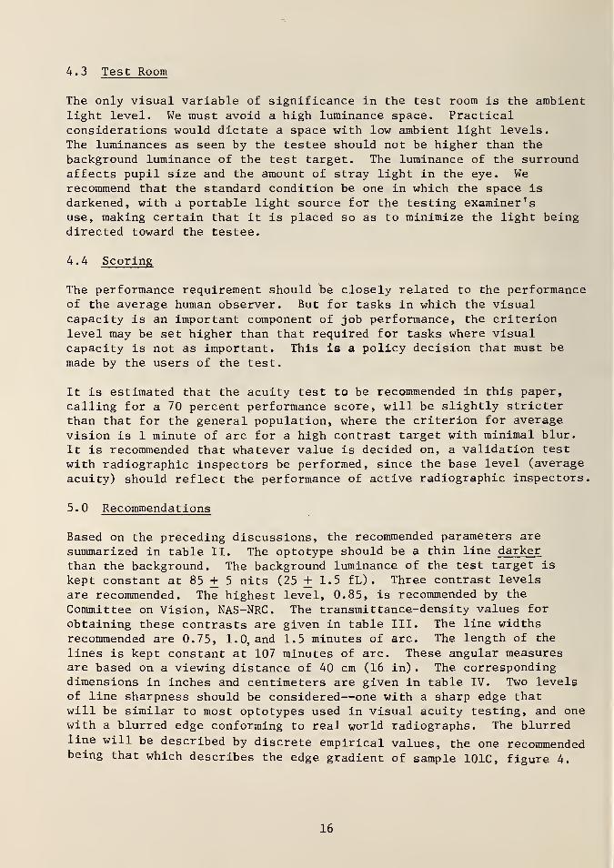
4.3 Test Room
The only visual variable of significance in the test room is the ambientlight level. We must avoid a high luminance space. Practicalconsiderations would dictate a space with low ambient light levels.
The luminances as seen by the testee should not be higher than the
background luminance of the test target. The luminance of the surroundaffects pupil size and the amount of stray light in the eye. Werecommend that the standard condition be one in which the space is
darkened, with a portable light source for the testing examiner'suse, making certain that it is placed so as to minimize the light beingdirected toward the testee.
4.4 Scoring
The performance requirement should be closely related to the performanceof the average human observer. But for tasks in which the visualcapacity is an important component of job performance, the criterionlevel may be set higher than that required for tasks where visualcapacity is not as important. This is a policy decision that must bemade by the users of the test.
It is estimated that the acuity test to be recommended in this paper,
calling for a 70 percent performance score, will be slightly stricterthan that for the general population, where the criterion for average
vision is 1 minute of arc for a high contrast target with minimal blur.
It is recommended that whatever value is decided on, a validation test
with radiographic inspectors be performed, since the base level (average
acuity) should reflect the performance of active radiographic inspectors.
5. Recommendations
Based on the preceding discussions, the recommended parameters are
summarized in table II. The optotype should be a thin line darker
than the background. The background luminance of the test target is
kept constant at 85 + 5 nits (25 + 1.5 fL) . Three contrast levels
are recommended. The highest level, 0.85, is recommended by the
Committee on Vision, NAS-NRC. The transmittance-density values for
obtaining these contrasts are given in table III. The line widthsrecommended are 0.75, 1.0, and 1.5 minutes of arc. The length of the
lines is kept constant at 107 minutes of arc. These angular measuresare based on a viewing distance of 40 cm (16 in) . The correspondingdimensions in inches and centimeters are given in table IV. Two levelsof line sharpness should be considered—one with a sharp edge thatwill be similar to most optotypes used in visual acuity testing, and onewith a blurred edge conforming to real world radiographs. The blurredline will be described by discrete empirical values, the one recommendedbeing that which describes the edge gradient of sample 101C, figure 4.
16

Table II. Visual Acuity Test Parameters
Variable
Figure-Ground
Background Luminance (nit/ftL)
Contrast
Line Width (minutes)
Line Length (minutes)
Viewing Distance (cm/in)
Blur
Line Orientation
Light Source (viewer)
Number of CondiConditions
1 Dark on light
1 85 ± 5/25 ± 1.5
3 0.1, 0.3, 0.85
3 0.75, 1.0, 1.5
1 107
1 40/16
2 Sharp, blurred
4 Perpend icular/hoblique right/left
Incandescent, fluorescent
Total (combinations) 72
17

Table III. Transmittance-Density of Visual Acuity Test Targets
Line
Contrast Transittance Density
0.1 0.018 1.74
0.3 0.014 1.85
0.85 0.003 2.52
Background
Transmit tance Density
0.02 1.70
0.02 1.70
0.02 1.70
18

Table IV. Dimensions of Line Target
Width
Minutes* Inches Centimeter
0.75 0.0035 0.0087
1.0 0.0047 0.0116
1.5 0.0070 0.0175
Length
107 0.5 1.24
*Viewing distance = 40 cm (16 in)
19

Samples of the reference test targets are presented in figure 8. Therelevant parameters of the reference test have been described, exceptfor line orientation. Line orientation as a parameter serves two im-portant functions: (1) it increases the number of possible responses(two with no orientation to four with the orientations recommended inthis report), and (2) it includes astigmatic effects. The four
orientations are horizontal (H) , vertical (V), oblique-right (R) , andoblique-left (L) . Contribution by guessing can be decreased bydividing the targets into four quadrants with the subject being requiredto denote which quadrant the line is in, in addition to the orientationof the line. This additional precaution should not be necessary, butserves the purpose of decreasing the probable contribution by guessingfrom 1/4 to (1/4) (1/4) = 1/16.
These targets will be used for self testing (intra-inspector assess-ment) as well as testing by designated examiners (inter-inspectordifferences) . The front of the slide (see figure 8) will be blankwith all necessary information given on the reverse side. Thisprocedure assumes that for self testing the examinee will not cheat,and will look at the side giving the correct response (H, V, R, or L)
only after evaluating the target orientation. When used by profes-sional examiners, they will be looking at the side with the targetinformation.
These slides are to be used with a standard dimmable radiographicviewer, masked so that only a 5 cm (2 in) square is exposed. The lightsource for the viewer would be incandescent or fluorescent lamps.
The test room should be darkened with a portable light source for theexaminer but in no case should the luminance be higher than 85 nits(25 fL) within the testee's field of view.
The actual performance by experienced radiographic inspectors cannot bepredicted at present. It is recommended that a validation test withradiographic inspectors be performed, the passing score based on theperformance for the above test, and the actual scoring includingpolicy considerations. For example, since visual acuity is animportant job-related requirement, how severe should we make the
acuity requirements?
20

FRONT BACK
Vertical
Contrast 0.85
Sharp
Rotated 90°
Horizontal
Contrast 0.85
Sharp
Oblique/Left
Contrast QJ.
Blurred
Rotated 90°
Oblique/Right
Contrast 01
Blurred
i0.5"
T s
0.85 V
oo1
inoo
•
s
0.85 H
—
09
B
0.1 L
30
/
B
0.1 R
CO
\
Figure 8. Examples of reference acuity tests showing line orientationsand dimensions. See text for complete description.
21

6.0 References
1. Brock, J. F.; Wells, R. G.; Abrams, M. L. Developments andValidation of an Experimental Radiograph Reading TrainingProgram. Report TR 74-33, Navy Personnel Research and DevelopmentConfer, San Diego, California, NTIS AD782 332, June, 1974.
2. Megling, R. C; Abrams, M. L. Relative Roles of Experience/Learning and Visual Factors on Radiographic Inspector Performance.Research Report SRR 73-22, Naval Personnel and Training ResearchLaboratory, San Diego, California, June, 1973.
3. Gulley, L. R. Proceedings, Interdisciplinary Workshop forQuantitative Flaw Definition, AFML-TR-74-738, Air Force MaterialsLaboratory, Nov. 1974, pp. 5-81.
4. Lewis, W. H. ; Sproat, W. H. ; Dodd, B. D.; Hamilton, J. M.
Reliability of Nondestructive Inspections - Final Report, SA-ALC/MME 76-6-38-1, San Antonio Air Logistics Center, Kelly Air ForceBase, San Antonio, Texas, Dec. 1978.
5. Mueller, C. G. Frequency of Seeing Functions for IntensityDiscrimination at Various Levels of Adapting Intensity. J. Gen.Physiol. (34): 1951, 463-474.
6. Yonemura, G. T. Considerations and Standards for Visual InspectionTechniques. In ASTM STP No. 624 Nondestructive Testing Standards- A Review. H. Berger (ed.) 1977, 220-230.
7. National Center for Health Statistics, Binocular Visual Acuity of
Adults, United States 1960-1962. Public Health Service PublicationNo. 1000-Series 11-No. 3, June 1964.
8. Committee on Vision, NAS-NRC. Recommended Standard Proceduresfor the Clinical Measurement and Specification of Visual Acuity.Adv. Ophthal. (41): 1980, 103-148.
9. Higgins, G. C; Jones, L. A. The Nature and Evaluation of the
Sharpness of Photographic Images. J. Soc. Mot. Pic. Telev. Eng
.
(58): 1952, 277-290.
10. Hecht, S.; Ross, S.; Mueller, C. G. The Visibility of Lines andSquares at High Brightness. J. Opt. Soc. Amer. (37): 1947,500-507.
11. Graham, C. H. ; Bartlett, N. R. The Relation of Size of Stimulusand Intensity in the Human Eye: III The Influence of Area onFoveal Intensity Discrimination. J. of Exp. Psychol. (27): 1940,149-159.
22

12. Perrin, F. H. Methods of Appraising Photographic Systems Part 1.
Historical Review. J. Opt. Soc. Amer. (69): 1960, 151-156.
13. Shlaer, S. The Relation Between Visual Acuity and Illumination.J. Gen. Physiol. (25): 1942, 553-569.
14. Shlaer, S.; Smith, E. L. ; Chase, A. M. Visual Acuity andIllumination in Different Spectral Regions. J. Gen. Physiol.(25): 1942, 553-569.
23

NBS-114A (REV. 2-8C)
2. Performing Organ. Report NoJ 3. Publication DateU.S. DEPT. OF COMM.
BIBLIOGRAPHIC DATASHEET (See instructions)
1. PUBLICATION ORREPORT NO.
NBS TN 1143 June 19814. TITLE AND SUBTITLE
Visual Acuity Testing of Radiographic Inspectors in Nondestructive Inspection
5. AUTHOR(S)
Gary T. Yonemura
6. PERFORMING ORGANIZATION (If joint or other than NBS. see instructions;
NATIONAL BUREAU OF STANDARDSDEPARTMENT OF COMMERCEWASHINGTON, D.C. 20234
7. Contract/Grant No.
8. Type of Report & Period Covered
Final
9. SPONSORING ORGANIZATION NAME AND COMPLETE ADDRESS (Street. City. State, ZIP)
Office of Nondestructive EvaluationNational Measurement LaboratoryNational Bureau of StandardsWashington, DC 20234
10. SUPPLEMENTARY NOTES
_JDocument describes a computer program; SF-185, FlPS Software Summary, is attached.
11. ABSTRACT (A 200-word or less factual summary of most significant information. If document includes a significantbibliography or literature survey, mention it here)
Visual acuity tests for radiographic inspectors should be correlated with the
type of tasks encountered in real world radiography. The testing procedures
should be capable of assessing differences in day to day performance of a
given inspector as well as the performance of one inspector relative to other
inspectors. Single line targets with specific parametric values for contrast,
width, and blur are recommended to provide a means for testing a radiographic
inspector for visual acuity. These targets may be used for periodic tests by
the employing organization or for more frequent self testing by the inspector.
Statistics from the National Health Survey, procedures recommended by the
NAS-NRC Committee on Vision and real world radiographs have been utilized in
arriving at recommended test configurations.
t
12. KEY WORDS (Six to twelve entries; alphabetical order; capitalize only proper names; and separate key words by semicolons)
Acuity tests; nondestructive testing; quality testing; radiograph evaluation;
visual inspection; visual testing
13. AVAILABILITY
Qx) Unlimited
Q For Official Distribution. Do Not Release to NTIS
Hvl Order From Superintendent of Documents, U.S. Government Printing Office, Washington, D.C.20402.
~3] Order From National Technical Information Service (NTIS), Springfield, VA. 22161
14. NO. OFPRINTED PAGES
29
15. Price
$2.50
•fcll.S. GOVERNMENT PRINTING OFFICEi 1981-340-997/1696USCOMM-DC 6043-P80

:
NBS TECHNICAL PUBLICATIONS
PERIODICALS
JOURNAL OF RESEARCH—The Journal of Research of the
National Bureau of Standards reports NBS research and develop-
ment in those disciplines of the physical and engineering sciences in
which the Bureau is active. These include physics, chemistry,
engineering, mathematics, and computer sciences. Papers cover a
broad range of subjects, with major emphasis on measurementmethodology and the basic technology underlying standardization.
Also included from time to time are survey articles on topics
closely related to the Bureau's technical and scientific programs.
As a special service to subscribers each issue contains complete
citations to all recent Bureau publications in both NBS and non-
NBS media. Issued six times a year. Annual subscription: domestic
SI 3: foreign SI 6.25. Single copy. $3 domestic: $3.75 foreign.
NOTE: The Journal was formerly published in two sections: Sec-
tion A "Physics and Chemistry" and Section B "Mathematical
Sciences."
DIMENSIONS/NBS—This monthly magazine is published to in-
form scientists, engineers, business and industry leaders, teachers,
students, and consumers of the latest advances in science andtechnology, with primary emphasis on work at NBS. The magazinehighlights and reviews such issues as energy research, fire protec-
tion, building technology, metric conversion, pollution abatement,
health and safety, and consumer product performance. In addi-
tion, it reports the results of Bureau programs in measurementstandards and techniques, properties of matter and materials,
engineering standards and services, instrumentation, andautomatic data processing. Annual subscription: domestic $11;
foreign $13.75.
NONPERIODICALS
Monographs—Major contributions to the technical literature onvarious subjects related to the Bureau's scientific and technical ac-
tivities.
Handbooks—Recommended codes of engineering and industrial
practice (including safety codes) developed in cooperation with in-
terested industries, professional organizations, and regulatory
bodies.
Special Publications— Include proceedings of conferences spon-
sored by NBS, NBS annual reports, and other special publications
appropriate to this grouping such as wall charts, pocket cards, andbibliographies.
Applied Mathematics Series— Mathematical tables, manuals andstudies of special interest to physicists, engineers, chemists,
biologists, mathematicians, computer programmers, and others
engaged in scientific and technical work
National Standard Reference Data Series— Provides quantitative
data on the physical and chemical properties of materials, com-piled from the world's literature and critically evaluated.
Developed under a worldwide program coordinated by NBS underthe authority of the National Standard Data Act (Public Law90-396).
NOTE: The principal publication outlet for the foregoing data is
the Journal of Physical and Chemical Reference Data (JPCRD)published quarterly for NBS by the American Chemical Society
(ACS) and the American Institute of Physics (A1P). Subscriptions,
reprints, and supplements available from ACS, 1 155 Sixteenth St.,
NW, Washington, DC 20056.
Building Science Series—Disseminates technical information
developed at the Bureau on building materials, components,
systems, and whole structures. The series presents research results,
test methods, and performance criteria related to the structural andenvironmental functions and the durability and safety charac-
teristics of building elements and systems.
Technical Notes—Studies or reports which are complete in them-
selves but restrictive in their treatment of a subject. Analogous to
monographs but not so comprehensive in scope or definitive in
treatment of the subject area. Often serve as a vehicle for final
reports of work performed at NBS under the sponsorship of other
government agencies.
Voluntary Product Standards—Developed under procedures
published by the Department of Commerce in Part 10, Title 15, of
the Code of Federal Regulations. The standards establish
nationally recognized requirements for products, and provide all
concerned interests with a basis for common understanding of the
characteristics of the products. NBS administers this program as a
supplement to the activities of the private sector standardizing
organizations.
Consumer information Series— Practical information, based on
NBS research and experience, covering areas of interest to the con-
sumer. Easily understandable language and illustrations provide
useful background knowledge for shopping in today's tech-
nological marketplace.
Order the above NBS publications from: Superintendent of Docu-
ments, Government Printing Office, Washington, DC 20402.
Order the following NBS publications—FIPS and NBSIR's—fromthe National Technical Information Services, Springfield, VA 22161
.
Federal Information Processing Standards Publications (FIPS
PUB)— Publications in this series collectively constitute the
Federal Information Processing Standards Register. The Register
serves as the official source of information in the Federal Govern-
ment regarding standards issued by NBS pursuant to the Federal
Property and Administrative Services Act of 1949 as amended.
Public Law 89-306 (79 Stat. 1127), and as implemented by Ex-
ecutive Order 11717(38 FR 12315, dated May II, 1973) and Part 6
of Title 15 CFR (Code of Federal Regulations).
NBS Interagency Reports (NBSIR)—A special series of interim or
final reports on work performed by NBS for outside sponsors
(both government and non-government). In general, initial dis-
tribution is handled by the sponsor; public distribution is by the
National Technical Information Services, Springfield, VA 22161,
in paper copy or microfiche form.

U.S. DEPARTMENT OF COMMERCENational Bureau of StandardsWashington, D C 20234
OFFICIAL BUSINESS
Penalty for Private Use. $300
POSTAGE AND FEES PAIDU.S. DEPARTMENT OF COMMERCE
COM-215
THIRD CLASS BULK RATE
.