utility planning fundamentals - gf piping systems
TRANSCRIPT

UtilityPlan, Build, Operate
Pla
n, B
uild
, Ope
rate
Uti
lity

Disclaimer
The technical data are not binding. They neither constitute expressly warranted characteristics nor guaranteed properties nor a
guaranteed durability. They are subject to modification. Our General Terms of Sale apply..
Technical Manual
Piping Systems in Utilities


Technical ManualPiping Systems in Utilities
Schaffhausen, November 2018

GF Piping Systems – Piping Systems in Utilities – (11.18) 5
Technical ManualPiping Systems in Utilities
I How to Use . . . . . . . . . . . . . . . . . . . . . . . . . . . . . . . . . . . . . . . . . . . . . . . . . . . . . . . . . . . . . . . . . . . . . . . . . . . . . . . . . . . . . . . . . . . . . . . . . . . . . . . . . . . . . . . . . . . . . . . . . . . . . . . . . . . . . . . . . . . . . . . .
II Introduction . . . . . . . . . . . . . . . . . . . . . . . . . . . . . . . . . . . . . . . . . . . . . . . . . . . . . . . . . . . . . . . . . . . . . . . . . . . . . . . . . . . . . . . . . . . . . . . . . . . . . . . . . . . . . . . . . . . . . . . . . . . . . . . . . . . . . . . . . . . . .
IV Plastic Piping Materials . . . . . . . . . . . . . . . . . . . . . . . . . . . . . . . . . . . . . . . . . . . . . . . . . . . . . . . . . . . . . . . . . . . . . . . . . . . . . . . . . . . . . . . . . . . . . . . . . . . . . . . . . . . . . .
III Application Solutions for Supply . . . . . . . . . . . . . . . . . . . . . . . . . . . . . . . . . . . . . . . . . . . . . . . . . . . . . . . . . . . . . . . . . . . . . . . . . . . . . . . . . . . . . . .
V Design and Laying . . . . . . . . . . . . . . . . . . . . . . . . . . . . . . . . . . . . . . . . . . . . . . . . . . . . . . . . . . . . . . . . . . . . . . . . . . . . . . . . . . . . . . . . . . . . . . . . . . . . . . . . . . . . . . . . . . . . . . . . . . . . .
VI ELGEF Plus System . . . . . . . . . . . . . . . . . . . . . . . . . . . . . . . . . . . . . . . . . . . . . . . . . . . . . . . . . . . . . . . . . . . . . . . . . . . . . . . . . . . . . . . . . . . . . . . . . . . . . . . . . . . . . . . . . . . . . . . . . . .
A Index . . . . . . . . . . . . . . . . . . . . . . . . . . . . . . . . . . . . . . . . . . . . . . . . . . . . . . . . . . . . . . . . . . . . . . . . . . . . . . . . . . . . . . . . . . . . . . . . . . . . . . . . . . . . . . . . . . . . . . . . . . . . . . . . . . . . . . . . . . . . . . . . . . . . . . . . . . . . . . .
6 GF Piping Systems – Piping Systems in Utilities – (11.18)
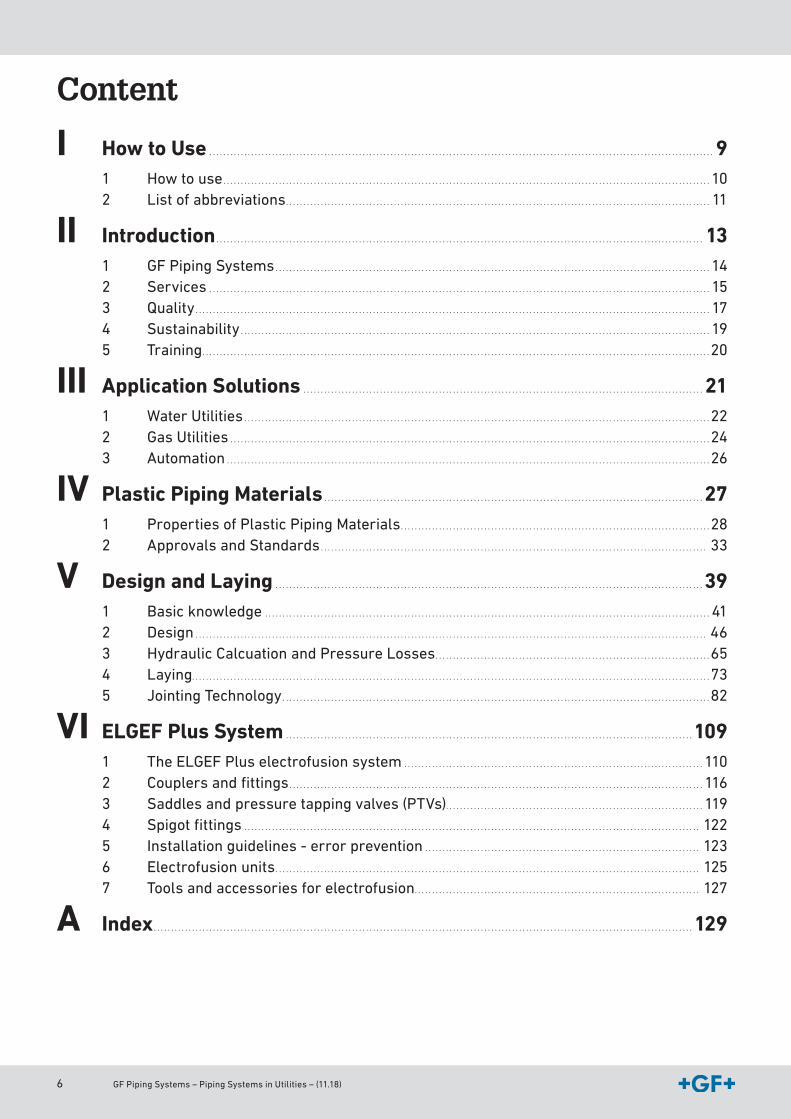
Content
I How to Use . . . . . . . . . . . . . . . . . . . . . . . . . . . . . . . . . . . . . . . . . . . . . . . . . . . . . . . . . . . . . . . . . . . . . . . . . . . . . . . . . . . . . . . . . . . . . . . . . . . . . . . . . . . . . . . . . . . . . . . . . . . . . . . . . . . . . . . . . . . . . . . . . 91 How to use . . . . . . . . . . . . . . . . . . . . . . . . . . . . . . . . . . . . . . . . . . . . . . . . . . . . . . . . . . . . . . . . . . . . . . . . . . . . . . . . . . . . . . . . . . . . . . . . . . . . . . . . . . . . . . . . . . . . . . . . . . . . . . . . . . . . . . . . . . . . 102 List of abbreviations . . . . . . . . . . . . . . . . . . . . . . . . . . . . . . . . . . . . . . . . . . . . . . . . . . . . . . . . . . . . . . . . . . . . . . . . . . . . . . . . . . . . . . . . . . . . . . . . . . . . . . . . . . . . . . . . . . . . . . . . . . 11
II Introduction . . . . . . . . . . . . . . . . . . . . . . . . . . . . . . . . . . . . . . . . . . . . . . . . . . . . . . . . . . . . . . . . . . . . . . . . . . . . . . . . . . . . . . . . . . . . . . . . . . . . . . . . . . . . . . . . . . . . . . . . . . . . . . . . . . . . . . . . . . . . 131 GF Piping Systems . . . . . . . . . . . . . . . . . . . . . . . . . . . . . . . . . . . . . . . . . . . . . . . . . . . . . . . . . . . . . . . . . . . . . . . . . . . . . . . . . . . . . . . . . . . . . . . . . . . . . . . . . . . . . . . . . . . . . . . . . . . . . 142 Services . . . . . . . . . . . . . . . . . . . . . . . . . . . . . . . . . . . . . . . . . . . . . . . . . . . . . . . . . . . . . . . . . . . . . . . . . . . . . . . . . . . . . . . . . . . . . . . . . . . . . . . . . . . . . . . . . . . . . . . . . . . . . . . . . . . . . . . . . . . . . . . . 153 Quality . . . . . . . . . . . . . . . . . . . . . . . . . . . . . . . . . . . . . . . . . . . . . . . . . . . . . . . . . . . . . . . . . . . . . . . . . . . . . . . . . . . . . . . . . . . . . . . . . . . . . . . . . . . . . . . . . . . . . . . . . . . . . . . . . . . . . . . . . . . . . . . . . . . . 174 Sustainability . . . . . . . . . . . . . . . . . . . . . . . . . . . . . . . . . . . . . . . . . . . . . . . . . . . . . . . . . . . . . . . . . . . . . . . . . . . . . . . . . . . . . . . . . . . . . . . . . . . . . . . . . . . . . . . . . . . . . . . . . . . . . . . . . . . . . . . 195 Training . . . . . . . . . . . . . . . . . . . . . . . . . . . . . . . . . . . . . . . . . . . . . . . . . . . . . . . . . . . . . . . . . . . . . . . . . . . . . . . . . . . . . . . . . . . . . . . . . . . . . . . . . . . . . . . . . . . . . . . . . . . . . . . . . . . . . . . . . . . . . . . . . . 20
III Application Solutions . . . . . . . . . . . . . . . . . . . . . . . . . . . . . . . . . . . . . . . . . . . . . . . . . . . . . . . . . . . . . . . . . . . . . . . . . . . . . . . . . . . . . . . . . . . . . . . . . . . . . . . . . . . . . . . . . . . 211 Water Utilities . . . . . . . . . . . . . . . . . . . . . . . . . . . . . . . . . . . . . . . . . . . . . . . . . . . . . . . . . . . . . . . . . . . . . . . . . . . . . . . . . . . . . . . . . . . . . . . . . . . . . . . . . . . . . . . . . . . . . . . . . . . . . . . . . . . . . . 222 Gas Utilities . . . . . . . . . . . . . . . . . . . . . . . . . . . . . . . . . . . . . . . . . . . . . . . . . . . . . . . . . . . . . . . . . . . . . . . . . . . . . . . . . . . . . . . . . . . . . . . . . . . . . . . . . . . . . . . . . . . . . . . . . . . . . . . . . . . . . . . . . . 243 Automation . . . . . . . . . . . . . . . . . . . . . . . . . . . . . . . . . . . . . . . . . . . . . . . . . . . . . . . . . . . . . . . . . . . . . . . . . . . . . . . . . . . . . . . . . . . . . . . . . . . . . . . . . . . . . . . . . . . . . . . . . . . . . . . . . . . . . . . . . . . 26
IV Plastic Piping Materials . . . . . . . . . . . . . . . . . . . . . . . . . . . . . . . . . . . . . . . . . . . . . . . . . . . . . . . . . . . . . . . . . . . . . . . . . . . . . . . . . . . . . . . . . . . . . . . . . . . . . . . . . . . . . 271 Properties of Plastic Piping Materials . . . . . . . . . . . . . . . . . . . . . . . . . . . . . . . . . . . . . . . . . . . . . . . . . . . . . . . . . . . . . . . . . . . . . . . . . . . . . . . . . . . . . . . . . 282 Approvals and Standards . . . . . . . . . . . . . . . . . . . . . . . . . . . . . . . . . . . . . . . . . . . . . . . . . . . . . . . . . . . . . . . . . . . . . . . . . . . . . . . . . . . . . . . . . . . . . . . . . . . . . . . . . . . . . . . 33
V Design and Laying . . . . . . . . . . . . . . . . . . . . . . . . . . . . . . . . . . . . . . . . . . . . . . . . . . . . . . . . . . . . . . . . . . . . . . . . . . . . . . . . . . . . . . . . . . . . . . . . . . . . . . . . . . . . . . . . . . . . . . . . . . . 391 Basic knowledge . . . . . . . . . . . . . . . . . . . . . . . . . . . . . . . . . . . . . . . . . . . . . . . . . . . . . . . . . . . . . . . . . . . . . . . . . . . . . . . . . . . . . . . . . . . . . . . . . . . . . . . . . . . . . . . . . . . . . . . . . . . . . . . . 412 Design . . . . . . . . . . . . . . . . . . . . . . . . . . . . . . . . . . . . . . . . . . . . . . . . . . . . . . . . . . . . . . . . . . . . . . . . . . . . . . . . . . . . . . . . . . . . . . . . . . . . . . . . . . . . . . . . . . . . . . . . . . . . . . . . . . . . . . . . . . . . . . . . . . . 463 Hydraulic Calcuation and Pressure Losses . . . . . . . . . . . . . . . . . . . . . . . . . . . . . . . . . . . . . . . . . . . . . . . . . . . . . . . . . . . . . . . . . . . . . . . . . . . . . . . 654 Laying. . . . . . . . . . . . . . . . . . . . . . . . . . . . . . . . . . . . . . . . . . . . . . . . . . . . . . . . . . . . . . . . . . . . . . . . . . . . . . . . . . . . . . . . . . . . . . . . . . . . . . . . . . . . . . . . . . . . . . . . . . . . . . . . . . . . . . . . . . . . . . . . . . . . . 735 Jointing Technology . . . . . . . . . . . . . . . . . . . . . . . . . . . . . . . . . . . . . . . . . . . . . . . . . . . . . . . . . . . . . . . . . . . . . . . . . . . . . . . . . . . . . . . . . . . . . . . . . . . . . . . . . . . . . . . . . . . . . . . . . . . 82
VI ELGEF Plus System . . . . . . . . . . . . . . . . . . . . . . . . . . . . . . . . . . . . . . . . . . . . . . . . . . . . . . . . . . . . . . . . . . . . . . . . . . . . . . . . . . . . . . . . . . . . . . . . . . . . . . . . . . . . . . . . . . . . . 1091 The ELGEF Plus electrofusion system . . . . . . . . . . . . . . . . . . . . . . . . . . . . . . . . . . . . . . . . . . . . . . . . . . . . . . . . . . . . . . . . . . . . . . . . . . . . . . . . . . . . . . 1102 Couplers and fittings . . . . . . . . . . . . . . . . . . . . . . . . . . . . . . . . . . . . . . . . . . . . . . . . . . . . . . . . . . . . . . . . . . . . . . . . . . . . . . . . . . . . . . . . . . . . . . . . . . . . . . . . . . . . . . . . . . . . . . . 1163 Saddles and pressure tapping valves (PTVs) . . . . . . . . . . . . . . . . . . . . . . . . . . . . . . . . . . . . . . . . . . . . . . . . . . . . . . . . . . . . . . . . . . . . . . . . . . 1194 Spigot fittings . . . . . . . . . . . . . . . . . . . . . . . . . . . . . . . . . . . . . . . . . . . . . . . . . . . . . . . . . . . . . . . . . . . . . . . . . . . . . . . . . . . . . . . . . . . . . . . . . . . . . . . . . . . . . . . . . . . . . . . . . . . . . . . . . . . 1225 Installation guidelines - error prevention . . . . . . . . . . . . . . . . . . . . . . . . . . . . . . . . . . . . . . . . . . . . . . . . . . . . . . . . . . . . . . . . . . . . . . . . . . . . . . . 1236 Electrofusion units . . . . . . . . . . . . . . . . . . . . . . . . . . . . . . . . . . . . . . . . . . . . . . . . . . . . . . . . . . . . . . . . . . . . . . . . . . . . . . . . . . . . . . . . . . . . . . . . . . . . . . . . . . . . . . . . . . . . . . . . . . 1257 Tools and accessories for electrofusion . . . . . . . . . . . . . . . . . . . . . . . . . . . . . . . . . . . . . . . . . . . . . . . . . . . . . . . . . . . . . . . . . . . . . . . . . . . . . . . . . . 127
A Index . . . . . . . . . . . . . . . . . . . . . . . . . . . . . . . . . . . . . . . . . . . . . . . . . . . . . . . . . . . . . . . . . . . . . . . . . . . . . . . . . . . . . . . . . . . . . . . . . . . . . . . . . . . . . . . . . . . . . . . . . . . . . . . . . . . . . . . . . . . . . . . . . . . . . . . . . . . 129
GF Piping Systems – Piping Systems in Utilities – (11.18) 7
PrefaceGF Piping Systems is a major global provider of complete piping solutions for many
demanding applications in various market segments. Founded in 1802, Georg Fischer started
the first production of malleable iron fittings in 1864 and today is recognized as the pioneer in
the development of corrosion-free plastic piping systems for the safe and reliable conveyance
of liquids and gases. This technical handbook reflects more than 60 years of our experience
and know-how in the designing and manufacturing of plastic piping systems. Today, our
product portfolio consists of more than 60’000 products and we are supporting our
customers with products and services day to day around the globe.
The scope of these planning fundamentals is to offer a valuable support in planning and
selection of the proper materials and the most suitable product range for all main industrial
applications. In addition, the handbook provides extensive information about all jointing
technologies for plastic materials and gives technical advises in the installation of pipes,
fittings, valves, measurements and control, as well as actuation.
We strongly believe that the professional planning and the proper use of our comprehensive
product range are the base for reliability, safety and high quality.
We hope that, in this handbook, you will find the qualified support that you need for your daily
work. In case of special applications our worldwide technical engineers will be glad to assist
you.
We would like to thank everyone, who continues to support GF Piping Systems in its mission
to delivering more value to customers, through superior piping systems.
Schaffhausen, November 2018
Preface

8 GF Piping Systems – Piping Systems in Utilities – (11.18)

GF Piping Systems – Piping Systems in Utilities – (11.18) 9
How to Use
Content
1 How to use ................................................................................................................................10
2 List of abbreviations ................................................................................................................11
10 GF Piping Systems – Piping Systems in Utilities – (11.18)
How to use
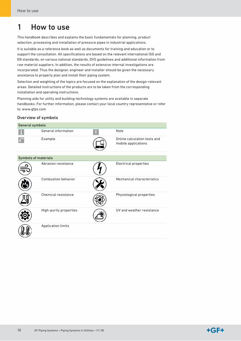
1 How to useThis handbook describes and explains the basic fundamentals for planning, product
selection, processing and installation of pressure pipes in industrial applications.
It is suitable as a reference book as well as documents for training and education or to
support the consultation. All specifi cations are based on the relevant international ISO and
EN standards, on various national standards, DVS guidelines and additional information from
raw material suppliers. In addition, the results of extensive internal investigations are
incorporated. Thus the designer, engineer and installer should be given the necessary
assistance to properly plan and install their piping system.
Selection and weighting of the topics are focused on the explanation of the design-relevant
areas. Detailed instructions of the products are to be taken from the corresponding
installation and operating instructions.
Planning aids for utility and building-technology systems are available in separate
handbooks. For further information, please contact your local country representative or refer
to: www.gfps.com
Overview of symbols
General symbols
General information Note
Example Online calculation tools and mobile applications
Symbols of materials
Abrasion resistance Electrical properties
Combustion behavior Mechanical characteristics
Chemical resistance Physiological properties
High-purity properties UV and weather resistance
Application limits
GF Piping Systems – Piping Systems in Utilities – (11.18) 11
How to UseList of abbreviations
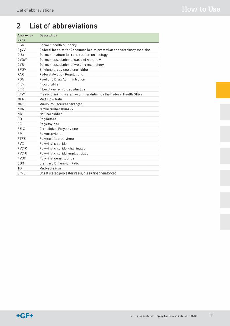
2 List of abbreviationsAbbrevia-tions
Description
BGA German health authorityBgVV Federal Institute for Consumer health protection and veterinary medicine
DIBt German Institute for construction technology
DVGW German association of gas and water e.V.
DVS German association of welding technology
EPDM Ethylene propylene diene rubber
FAR Federal Aviation Regulations
FDA Food and Drug Administration
FKM Fluororubber
GFK Fiberglass reinforced plastics
KTW Plastic drinking water recommendation by the Federal Health Office
MFR Melt Flow Rate
MRS Minimum Required Strength
NBR Nitrile rubber (Buna-N)
NR Natural rubber
PB Polybutene
PE Polyethylene
PE-X Crosslinked Polyethylene
PP Polypropylene
PTFE Polytetrafluorethylene
PVC Polyvinyl chloride
PVC-C Polyvinyl chloride, chlorinated
PVC-U Polyvinyl chloride, unplasticized
PVDF Polyvinylidene fluoride
SDR Standard Dimension Ratio
TG Malleable iron
UP-GF Unsaturated polyester resin, glass fiber reinforced
12 GF Piping Systems – Piping Systems in Utilities – (11.18)
How to use
GF Piping Systems – Piping Systems in Utilities – (11.18) 1 · 13
Introduction
Content
1 GF PipingSystems ...................................................................................................................14
2 Services ....................................................................................................................................15
3 Quality .......................................................................................................................................173.1 Qualityassuranceatalllevels . . . . . . . . . . . . . . . . . . . . . . . . . . . . . . . . . . . . . . . . . . . . . . . . . . . . . . . . . . . . . . . . . . . . . . . . . . . . . . . . . . . . . . . . . . . . . . . . . . . . . . . . . . . . . . . . . . . . . . . . 17
3.2 Managementsystems . . . . . . . . . . . . . . . . . . . . . . . . . . . . . . . . . . . . . . . . . . . . . . . . . . . . . . . . . . . . . . . . . . . . . . . . . . . . . . . . . . . . . . . . . . . . . . . . . . . . . . . . . . . . . . . . . . . . . . . . . . . . . . . . . . . . . . . 17
3.3 Accreditedtestcenter . . . . . . . . . . . . . . . . . . . . . . . . . . . . . . . . . . . . . . . . . . . . . . . . . . . . . . . . . . . . . . . . . . . . . . . . . . . . . . . . . . . . . . . . . . . . . . . . . . . . . . . . . . . . . . . . . . . . . . . . . . . . . . . . . . . . . . . 17
4 Sustainability ...........................................................................................................................194.1 Environment . . . . . . . . . . . . . . . . . . . . . . . . . . . . . . . . . . . . . . . . . . . . . . . . . . . . . . . . . . . . . . . . . . . . . . . . . . . . . . . . . . . . . . . . . . . . . . . . . . . . . . . . . . . . . . . . . . . . . . . . . . . . . . . . . . . . . . . . . . . . . . . . . . . . . . . 19
4.2 Socialaspects . . . . . . . . . . . . . . . . . . . . . . . . . . . . . . . . . . . . . . . . . . . . . . . . . . . . . . . . . . . . . . . . . . . . . . . . . . . . . . . . . . . . . . . . . . . . . . . . . . . . . . . . . . . . . . . . . . . . . . . . . . . . . . . . . . . . . . . . . . . . . . . . . . . . 19
5 Training .....................................................................................................................................20
I
1 · 14 GF Piping Systems – Piping Systems in Utilities – (11.18)
GF PipingSystems
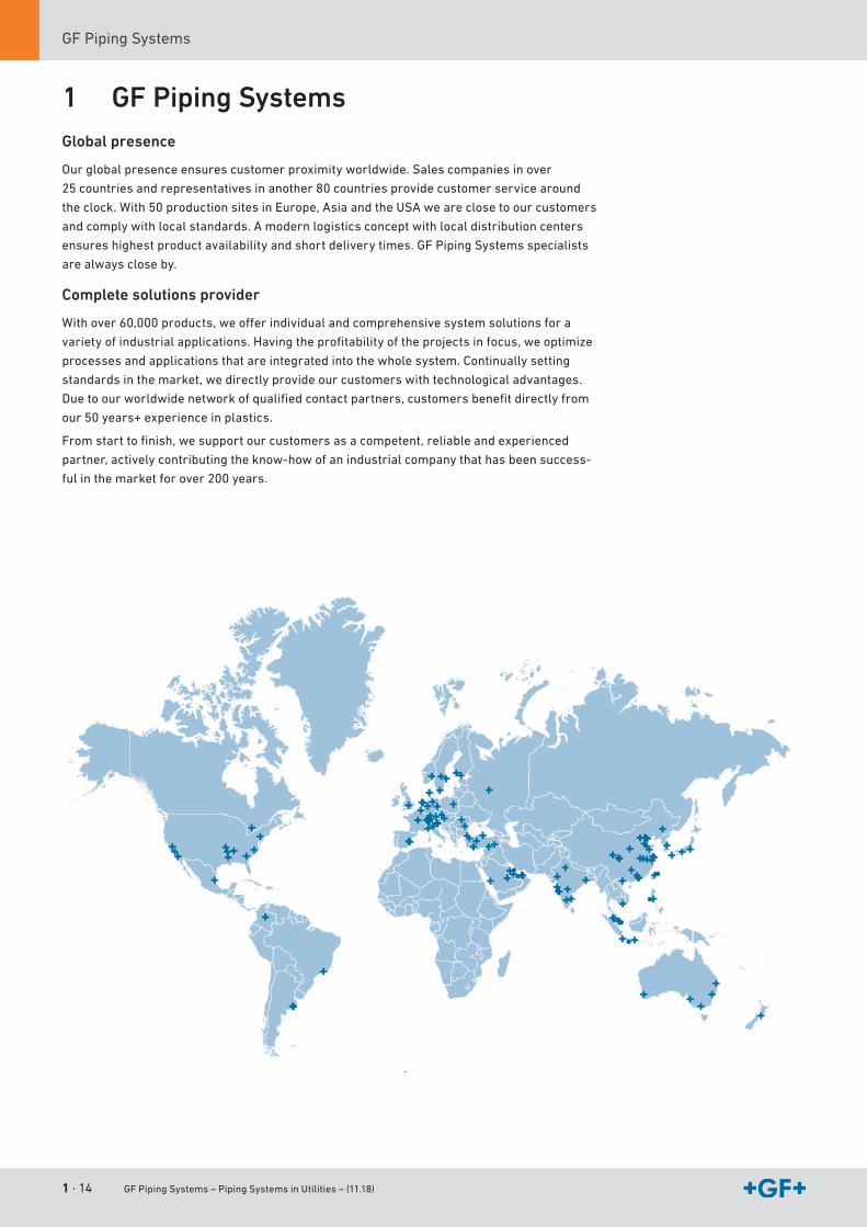
1 GF Piping SystemsGlobal presence
Ourglobalpresenceensurescustomerproximityworldwide.Salescompaniesinover
25 countriesandrepresentativesinanother80countriesprovidecustomerservicearound
theclock.With50productionsitesinEurope,AsiaandtheUSAweareclosetoourcustomers
andcomplywithlocalstandards.Amodernlogisticsconceptwithlocaldistributioncenters
ensureshighestproductavailabilityandshortdeliverytimes.GF PipingSystemsspecialists
arealwayscloseby.
Complete solutions provider
Withover60,000products,weofferindividualandcomprehensivesystemsolutionsfora
varietyofindustrialapplications.Havingtheprofitabilityoftheprojectsinfocus,weoptimize
processesandapplicationsthatareintegratedintothewholesystem.Continuallysetting
standardsinthemarket,wedirectlyprovideourcustomerswithtechnologicaladvantages.
Duetoourworldwidenetworkofqualifiedcontactpartners,customersbenefitdirectlyfrom
our50years+experienceinplastics.
Fromstarttofinish,wesupportourcustomersasacompetent,reliableandexperienced
partner,activelycontributingtheknow-howofanindustrialcompanythathasbeensuccess-
fulinthemarketforover200years.
GF Piping Systems – Piping Systems in Utilities – (11.18) 1 · 15
IntroductionServices
I
2 ServicesFrom planning support to implementation – our specialists are always close by
Asaleadingproviderofpipingsystemsinplastic,weofferourcustomersnotonlyreliable
products,butalsoacomprehensivepackageofservices.Oursupportrangesfroma
comprehensivetechnicalmanualortheextensiveCADlibrarytoaninternationalteamof
experts,whoworkcloselytogetherwithlocalsalescompanies.Andwhenitcomesto
implementingaproject,ourcustomersadditionallybenefitfromawiderangeoftraining
courses,eitheronsiteorinourmoderntrainingcentersworldwide.
a Chemical resistance
Ourspecialistteamshavedecadesofexperienceintheareaofchemicalresistance.Theycan
offerindividualsupportandadviceinselectingtherightmaterialforthecorresponding
plasticssystemsolution.Onrequest,ateamwillexamineandselecttheappropriatematerial
forspecialapplications.
s CAD library
TheextensiveCADlibraryisthemostfrequentlyusedplanningtoolatGF PipingSystems.The
databasecomprisesover30,000drawingsandtechnicaldataregardingpipes,fittings,
measurementandcontroltechnologyaswellasmanualandactuatedvalves.Thebig
advantageoftheCADlibraryisthatthedatacanbeintegrateddirectlyinCADmodels.
d Technical support
Technicalsupportandmaterialselectionarekeyfactorsforasuccessfulinstallation.Ateam
ofspecialistsheadquarteredinSwitzerlandisavailabletosupporttheGF PipingSystems
salescompaniesaroundtheworld.Fortechnicaladviceorforgeneralinformation,our
customersaresupportedindividuallybythespecialistteaminthecorrespondingsales
company.
f Online and mobile calculation tools
Ournumerous,multilingualonlinecalculationtoolsareveryusefulforconfiguringand
calculating.Bymeansofpressure/temperaturediagrams,thepressureofliquidmedia
recommendedforpipesandfittingsatvarioustemperaturescanbeeasilydefined.FlowCalc
App,themobileapplicationofGF PipingSystems,isanon-siteplanningtoolforpipediameter
andflowvelocitycalculationtoselecttherightdimensionofpipingsystems.
g On-site training
Ourexpertsareavailabletosupportourcustomerslocallyandconducttrainingindiverse
fusionandjointingtechniquesonlocation.Thedurationandstructureofthetrainingdepends
ontheprojectandthesystembeinginstalled.
h Customizing
ThecustomizingteamsatGFPipingSystemsworkcloselytogetheraroundtheglobe.The
focusofourteamsisontheproductionofcustom-madespecialpartstocomplete
installations.Inaddition,awidevarietyofspecialsolutionscanbeproducedinsmallseries.
Standardizedprocessesguaranteeourcustomersthehighestquality,evenforindividual
solutions.
1 · 16 GF Piping Systems – Piping Systems in Utilities – (11.18)
Services
j Rental pool
Inmanycountries,GF PipingSystemsprovidesmachinesandtoolstorentforvariousjoining
techniquessuchasbuttwelding,electrofusionandmechanicalconnections.
k Training courses
GF PipingSystemsoffersawiderangeoftrainingcoursesthatallowparticipantstogain
confidenceinworkingwithourproductsandprovenjointingtechnologies.Thepractical
trainingisclearlydefined,structuredandadaptedtothevariouslevelsofexperienceofthe
participants.
l Fit for Service NDT
Usingultrasoundtechnology,weareabletoprovideourcustomerswithtop-qualitynon-
destructivetesting(NDT)forecoFIT(PE),PROGEF(PP)buttweldsandELGEF(PE)
electrofusionwelds.ImportantprojectsacrossthegloberelyonNDTtechnologytoensure
thegreatestsecurityandqualityofweldedjointsonmetallicpipes.GF PipingSystems’
approachtoholisticqualitymanagementhasresultedintheworld’sfirstNDTserviceforbutt
weldsandelectrofusionweldsonecoFIT(PE),PROGEF(PP)andELGEF(PE)withan
operationalfitnessreport(pass/fail).Onceanitemhaspassed,weprovideaten-year
guarantee.
OuruniqueNDTsolutionguaranteesyourweldqualitywithapass/failreport.
; Track and Trace
TrackandTraceisacompletemanagementpackagethattakescareofpreparation,dataentry
anddataarchivingatallcriticalphasesonaconstructionsite.State-of-the-artapps,Internet
platforms,onlineclouds,mobiledevicesandGPShardwareareusedforthis.Theserviceis
availableasanannuallicenceandcontainsalltherequiredelementstoplan,manageand
implementinstallationsinanintelligent,quality-drivenandsmoothprocess.
A Advanced Engineering Services
Inordertosupportkeyprojectsacrossallprojectphases,weprovideadvancedengineering
servicesforthedesign,installationandverificationofsystems.Advancedengineering
servicesprovidesupportforeverycustomerrequirement:
• Modificationofparts
• Materialselection
• Designreviews
• Detailingofstandards
• Hydraulicmodeling
• Dynamic-mechanicaltensionanalysis
• Calculationofstaticanalyses
• FEA/FEM
Toguaranteesafe,highperformanceplasticpipingsystems,allinvolvedcalculationsare
performedusingprofessionalprogramssuchasROHR2.
GF Piping Systems – Piping Systems in Utilities – (11.18) 1 · 17
IntroductionQuality
I
3 Quality
3.1 Quality assurance at all levelsQualitycreatessafetyandisthebasisfortrust.Incustomerrelationshipsaswellasin
projectwork,development,productionandinthespecificapplicationofproducts,quality
awarenessandstandardsdecideonsustainedsuccess.Thefundamentalimportanceof
qualitydeterminesouractions,shapesourunderstandingofquality,andisreflectedinour
ownclaimtoquality.
Thesystematicintegrationofpartnersandsuppliersispartofourcomprehensive
understandingofqualityandguaranteesthebindingassuranceofthequalitystandardalong
theentirevalueaddedchain.
GF PipingSystemsisboundtothehighqualitystandardsofitscustomersandconsidersitself
activelyresponsibleformeetingthecustomerrequirementsaswellasensuringlegal
standards.Therigorousimplementationofourqualitypolicyrepresentsanobligationfor
everysingleperson.Consequently,theorientationtowardsqualitywhenprovidingaservice
goeswithoutsayingforallemployeesworkinginthecompany.
3.2 Management systemsQuality,environment,occupationalsafetyandhealthprotectionhavealwaysplayedavery
importantroleintheGeorgFischergroup.Inlinewiththat,allproductioncompaniesaswell
asmanysalescompaniesofGF PipingSystemsarecertifiedinaccordancewiththeISO9001
qualitymanagementsystem.Furthermore,allofourproductionsitesarecertifiedin
accordancewithISO14001.Thestandarddefinescriteriathatareapplicablethroughoutthe
worldforefficientenvironmentalmanagementsystemsand,asaresult,isconsideredtobe
thebasisforoptimizingenvironmentallyrelevantprocesses.
Aspartofoursustainabilityactivities,allproductionsiteshavealsobeencertifiedin
accordancewithOHSAS18001,theinternationalstandardintheareaofoccupationalhealth
andsafety.Newlyacquiredornewlyfoundedproductioncompaniesareboundtoestablisha
quality,environmentalandoccupationalsafetymanagementregimewithinaperiodofthree
years.
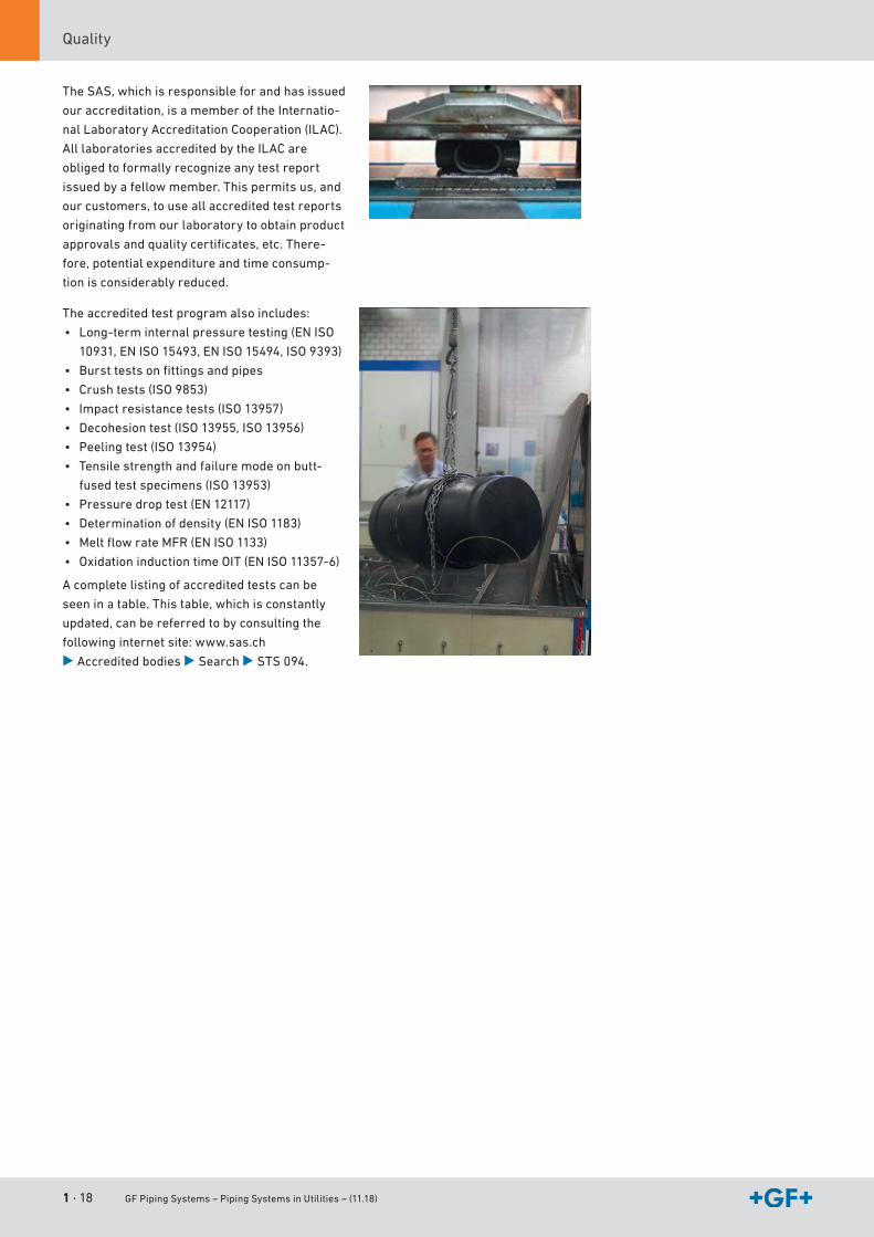
3.3 Accredited test centerThetestcenterofGF PipingSystemsisatestcenteraccreditedinaccordancewithISO/IEC
17025forcomponentsofpipingsystems.Itinspectsalltypesofpipes,pipeconnections,
connectingelements,fittings,manualandautomaticvalvesaswellasflowmetersaccording
torelevantstandardsanditsownexternalaswellasinternalspecifications.
CustomersfortestlaboratoryprogramsaretheR&Ddepartments,manufacturingplants,as
wellasend-usersofGF PipingSystemscomponentsandotherexternalcustomers.
DevelopmentandproductreleasetestsarecompletedforR&Ddepartments(TTtypetesting,
ITTinitialtypetesting),batchreleasetests(BRT)andprocessverificationtests(PVT)forour
ownproductionunitsaswellasothertestsforexternalcustomers.
Thecontinuoustrainingandspecificexperienceofouremployees,thetechnicalstateofour
testingsystems,aswellasproperlydocumentedtestsequencesarebasicprerequisitesto
accreditingthetestcenterinaccordancewithISO/IEC17025.TheaccreditationbySAS(Swiss
AccreditationOffice)isconfirmedintheformofacertificate.Averificationtakesplace
annuallyaswellasarenewaloftheaccreditationevery5years.
1 · 18 GF Piping Systems – Piping Systems in Utilities – (11.18)
Quality
TheSAS,whichisresponsibleforandhasissued
ouraccreditation,isamemberoftheInternatio-
nalLaboratoryAccreditationCooperation(ILAC).
AlllaboratoriesaccreditedbytheILACare
obligedtoformallyrecognizeanytestreport
issuedbyafellowmember.Thispermitsus,and
ourcustomers,touseallaccreditedtestreports
originatingfromourlaboratorytoobtainproduct
approvalsandqualitycertificates,etc.There-
fore,potentialexpenditureandtimeconsump-
tionisconsiderablyreduced.
Theaccreditedtestprogramalsoincludes:
• Long-terminternalpressuretesting(ENISO
10931,ENISO15493,ENISO15494,ISO9393)
• Bursttestsonfittingsandpipes
• Crushtests(ISO9853)
• Impactresistancetests(ISO13957)
• Decohesiontest(ISO13955,ISO13956)
• Peelingtest(ISO13954)
• Tensilestrengthandfailuremodeonbutt-
fusedtestspecimens(ISO13953)
• Pressuredroptest(EN12117)
• Determinationofdensity(ENISO1183)
• MeltflowrateMFR(ENISO1133)
• OxidationinductiontimeOIT(ENISO11357-6)
Acompletelistingofaccreditedtestscanbe
seeninatable.Thistable,whichisconstantly
updated,canbereferredtobyconsultingthe
followinginternetsite:www.sas.ch
B Accredited bodiesBSearchBSTS094.

GF Piping Systems – Piping Systems in Utilities – (11.18) 1 · 19
IntroductionSustainability
I
4 SustainabilityAs an internationally operating industrial group, GF is in the midst of society. It is, therefore, important to harmonize economy, ecology and social aspects. In accordance with this responsibility, our industrial and social activities carry a long-term and long-range orientation. It is our endeavor to anchor sustainability in all of our sales companies. Our sustainability goals, whose attainment we communicate regularly and transparently, drive our actions.
4.1 EnvironmentForGF PipingSystems,ourownenvironmentalresponsibilityisanintegralaspectinallofour
businessactivities.Becauseweregardenvironmentalawarenessasoneofthemost
importantvaluesofourcompany,allinternalstructuresandprocessesareorientedtowards
sustainability.Westrivetosavenaturalresourcesandworkrelentlesslyonoptimizingthe
eco-friendlinessofourproductsandtheirapplications.Outstandingmaterialpropertiesand
innovativetechnologiesformthebasisofourenvironmentallyfriendlyandenergy-saving
solutions.Bysupplyingourcustomerswithcompletepipingsystems,wesupportand
promoteecologicalandcost-efficientoperatingprocessesinmanyindustriesandindaily
routine.Toobtaindetailedinformationabouttheenvironmentalcompatibilityofourproducts,
wemonitorallphasesoftheproductlifecycleindetail,whichalsoallowsusultimatelyto
improvethelifecycleassessmentofourproducts.
4.2 Social aspectsAttractiveworkplaces,interestingtasks,agoal-orientedtrainingandprofessional
development,aswellasafairsalaryandgoodsocialbenefitscontributetosecuringthe
futureofthecompany.GF PipingSystemsoperateswiththisresponsibilityasitspremise.
Withlocationsinover30countries,GF PipingSystemsviewsthemultitudeofcultures,
religions,nationalities,gendersandagegroupsasavaluablesourcefortalent,creativityand
experience.Thismakespossibletheextraordinaryservicesperformedbyapproximately
16,000staffmembersemployedbyGF PipingSystemsthroughouttheworld.
Additional information about sustainability can be found at
www.gfps.com/sustainability.
1 · 20 GF Piping Systems – Piping Systems in Utilities – (11.18)
Training
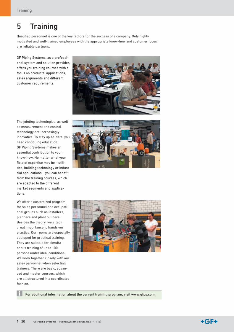
5 TrainingQualifiedpersonnelisoneofthekeyfactorsforthesuccessofacompany.Onlyhighly
motivatedandwell-trainedemployeeswiththeappropriateknow-howandcustomerfocus
arereliablepartners.
GF PipingSystems,asaprofessi-
onalsystemandsolutionprovider,
offersyoutrainingcourseswitha
focusonproducts,applications,
salesargumentsanddifferent
customerrequirements.
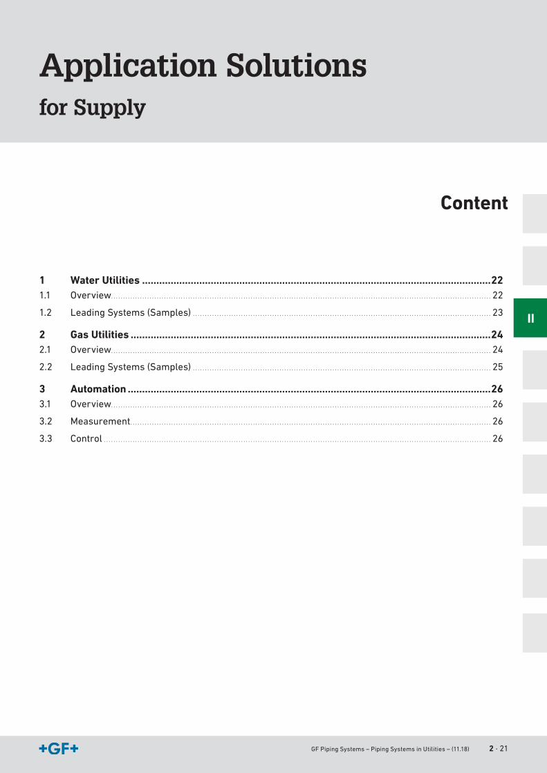
Thejointingtechnologies,aswell
asmeasurementandcontrol
technologyareincreasingly
innovative.Tostayup-to-date,you
needcontinuingeducation.
GF PipingSystemsmakesan
essentialcontributiontoyour
know-how.Nomatterwhatyour
fieldofexpertisemaybe–utili-
ties,buildingtechnologyorindust-
rialapplications–youcanbenefit
fromthetrainingcourses,which
areadaptedtothedifferent
marketsegmentsandapplica-
tions.
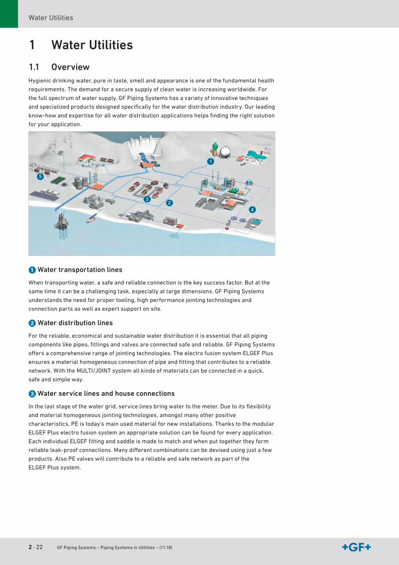
Weofferacustomizedprogram
forsalespersonnelandoccupati-
onalgroupssuchasinstallers,
plannersandplantbuilders.
Besidesthetheory,weattach
greatimportancetohands-on
practice.Ourroomsareespecially
equippedforpracticaltraining.
Theyaresuitableforsimulta-
neoustrainingofupto100
personsunderidealconditions.
Weworktogethercloselywithour
salespersonnelwhenselecting
trainers.Therearebasic,advan-
cedandmastercourses,which
areallstructuredinacoordinated
fashion.
For additional information about the current training program, visit www.gfps.com.
GF Piping Systems – Piping Systems in Utilities – (11.18) 2 · 21
Application Solutionsfor Supply
Content
1 Water Utilities ..........................................................................................................................221.1 Overview . . . . . . . . . . . . . . . . . . . . . . . . . . . . . . . . . . . . . . . . . . . . . . . . . . . . . . . . . . . . . . . . . . . . . . . . . . . . . . . . . . . . . . . . . . . . . . . . . . . . . . . . . . . . . . . . . . . . . . . . . . . . . . . . . . . . . . . . . . . . . . . . . . . . . . . . . . . . . . 22
1.2 LeadingSystems(Samples) . . . . . . . . . . . . . . . . . . . . . . . . . . . . . . . . . . . . . . . . . . . . . . . . . . . . . . . . . . . . . . . . . . . . . . . . . . . . . . . . . . . . . . . . . . . . . . . . . . . . . . . . . . . . . . . . . . . . . . . . . . . . 23
2 Gas Utilities ..............................................................................................................................242.1 Overview . . . . . . . . . . . . . . . . . . . . . . . . . . . . . . . . . . . . . . . . . . . . . . . . . . . . . . . . . . . . . . . . . . . . . . . . . . . . . . . . . . . . . . . . . . . . . . . . . . . . . . . . . . . . . . . . . . . . . . . . . . . . . . . . . . . . . . . . . . . . . . . . . . . . . . . . . . . . . . 24
2.2 LeadingSystems(Samples) . . . . . . . . . . . . . . . . . . . . . . . . . . . . . . . . . . . . . . . . . . . . . . . . . . . . . . . . . . . . . . . . . . . . . . . . . . . . . . . . . . . . . . . . . . . . . . . . . . . . . . . . . . . . . . . . . . . . . . . . . . . . 25
3 Automation ...............................................................................................................................263.1 Overview . . . . . . . . . . . . . . . . . . . . . . . . . . . . . . . . . . . . . . . . . . . . . . . . . . . . . . . . . . . . . . . . . . . . . . . . . . . . . . . . . . . . . . . . . . . . . . . . . . . . . . . . . . . . . . . . . . . . . . . . . . . . . . . . . . . . . . . . . . . . . . . . . . . . . . . . . . . . . . 26
3.2 Measurement . . . . . . . . . . . . . . . . . . . . . . . . . . . . . . . . . . . . . . . . . . . . . . . . . . . . . . . . . . . . . . . . . . . . . . . . . . . . . . . . . . . . . . . . . . . . . . . . . . . . . . . . . . . . . . . . . . . . . . . . . . . . . . . . . . . . . . . . . . . . . . . . . . . . . . 26
3.3 Control . . . . . . . . . . . . . . . . . . . . . . . . . . . . . . . . . . . . . . . . . . . . . . . . . . . . . . . . . . . . . . . . . . . . . . . . . . . . . . . . . . . . . . . . . . . . . . . . . . . . . . . . . . . . . . . . . . . . . . . . . . . . . . . . . . . . . . . . . . . . . . . . . . . . . . . . . . . . . . . . . 26
II
2 · 22 GF Piping Systems – Piping Systems in Utilities – (11.18)
WaterUtilities
1 Water Utilities
1.1 OverviewHygienicdrinkingwater,pureintaste,smellandappearanceisoneofthefundamentalhealth
requirements.Thedemandforasecuresupplyofcleanwaterisincreasingworldwide.For
thefullspectrumofwatersupply,GF PipingSystemshasavarietyofinnovativetechniques
andspecializedproductsdesignedspecificallyforthewaterdistributionindustry.Ourleading
know-howandexpertiseforallwaterdistributionapplicationshelpsfindingtherightsolution
foryourapplication.
a Water transportation lines
Whentransportingwater,asafeandreliableconnectionisthekeysuccessfactor.Butatthe
sametimeitcanbeachallengingtask,especiallyatlargedimensions.GF PipingSystems
understandstheneedforpropertooling,highperformancejointingtechnologiesand
connectionpartsaswellasexpertsupportonsite.
s Water distribution lines
Forthereliable,economicalandsustainablewaterdistributionitisessentialthatallpiping
componentslikepipes,fittingsandvalvesareconnectedsafeandreliable.GF PipingSystems
offersacomprehensiverangeofjointingtechnologies.TheelectrofusionsystemELGEFPlus
ensuresamaterialhomogeneousconnectionofpipeandfittingthatcontributestoareliable
network.WiththeMULTI/JOINTsystemallkindsofmaterialscanbeconnectedinaquick,
safeandsimpleway.
d Water service lines and house connections
Inthelaststageofthewatergrid,servicelinesbringwatertothemeter.Duetoitsflexibility
andmaterialhomogeneousjointingtechnologies,amongstmanyotherpositive
characteristics,PEistoday’smainusedmaterialfornewinstallations.Thankstothemodular
ELGEF Pluselectrofusionsystemanappropriatesolutioncanbefoundforeveryapplication.
EachindividualELGEFfittingandsaddleismadetomatchandwhenputtogethertheyform
reliableleak-proofconnections.Manydifferentcombinationscanbedevisedusingjustafew
products.AlsoPEvalveswillcontributetoareliableandsafenetworkaspartofthe
ELGEF Plussystem.
GF Piping Systems – Piping Systems in Utilities – (11.18) 2 · 23
Application SolutionsWaterUtilities
II
f Pressure sewage lines
Ratherthangravity,thepressuresewagesystemisusingpumpstomovethewastewater
alongtothewastewatertreatmentplant.Pressuresewagesystemsareusinggenerally
smallerdiameterpipesthatarelessexpensiveandeasiertoinstall.ChoosingheretheGFPE
system,areliablenetworkfor100yearscanbebuilt.
g Irrigation
Agrowingworldpopulationandthechangingclimateenhancethefoodandwaterscarcity.
Moreandmorefoodproductionwillbeseparatedfromthelocalweatherbybuildinglarge
glasshousesordoingextendedirrigationincreasingtheoutputoffoodperm2.Systems
simpletoinstallandensuringasecurewaterdistributionoverthetotalproductlifespanwill
becomeanimportantattribute.GF PipingSystemsprovidesacomprehensiveproductrange
forirrigationaswellasonthelocaltrainingandfastdeliveries.
1.2 Leading Systems (Samples)ELGEF Plus MULTI/JOINT iJOINT Machines Tools
d160–d2000mm,PN10d20–d1200mm,PN16
DN50–DN600mm d16–d110mm Butt fusiond40mm–d1600mm(withCNCtechnologyuptod630mm)
d20–d2000mm
Electrofusionfittings,spigotfittings,seamlessbendsandsegmentedfittingsandpipes
Widerangerestraintcouplings,reductioncouplings,wide-rangeflanges,curves,endcapsPEadapters,footbends
Couplings,tees,bends,reducersandsaddles,transitionfittings,universalfittings
ElectrofusionMSA125,230,330,340(Transformer)
MSA2.0,2.1,4.0,4.1,2.0MULTI(Invertertechnology)
Rotationpeelers,clampingdevices,top-loadtools,cuttingtools,re-roundingtools,squeeze-offtools,tappingdevices
2 · 24 GF Piping Systems – Piping Systems in Utilities – (11.18)
GasUtilities
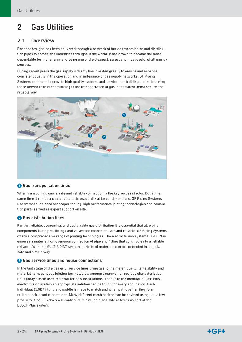
2 Gas Utilities
2.1 OverviewFordecades,gashasbeendeliveredthroughanetworkofburiedtransmissionanddistribu-
tionpipestohomesandindustriesthroughouttheworld.Ithasgrowntobecomethemost
dependableformofenergyandbeingoneofthecleanest,safestandmostusefulofallenergy
sources.
Duringrecentyearsthegassupplyindustryhasinvestedgreatlytoensureandenhance
consistentqualityintheoperationandmaintenanceofgassupplynetworks.GF Piping
Systemscontinuestoprovidehighqualitysystemsandservicesforbuildingandmaintaining
thesenetworksthuscontributingtothetransportationofgasinthesafest,mostsecureand
reliableway.
a Gas transportation lines
Whentransportinggas,asafeandreliableconnectionisthekeysuccessfactor.Butatthe
sametimeitcanbeachallengingtask,especiallyatlargerdimensions.GF PipingSystems
understandstheneedforpropertooling,highperformancejointingtechnologiesandconnec-
tionpartsaswellasexpertsupportonsite.
s Gas distribution lines
Forthereliable,economicalandsustainablegasdistributionitisessentialthatallpiping
componentslikepipes,fittingsandvalvesareconnectedsafeandreliable.GF PipingSystems
offersacomprehensiverangeofjointingtechnologies.TheelectrofusionsystemELGEFPlus
ensuresamaterialhomogeneousconnectionofpipeandfittingthatcontributestoareliable
network.WiththeMULTI/JOINTsystemallkindsofmaterialscanbeconnectedinaquick,
safeandsimpleway.
d Gas service lines and house connections
Inthelaststageofthegasgrid,servicelinesbringgastothemeter.Duetoitsflexibilityand
materialhomogeneousjointingtechnologies,amongstmanyotherpositivecharacteristics,
PE istoday’smainusedmaterialfornewinstallations.ThankstothemodularELGEFPlus
electrofusionsystemanappropriatesolutioncanbefoundforeveryapplication.Each
individualELGEFfittingandsaddleismadetomatchandwhenputtogethertheyform
reliableleak-proofconnections.Manydifferentcombinationscanbedevisedusingjustafew
products.AlsoPEvalveswillcontributetoareliableandsafenetworkaspartofthe
ELGEF Plussystem.
GF Piping Systems – Piping Systems in Utilities – (11.18) 2 · 25
Application SolutionsGasUtilities
II
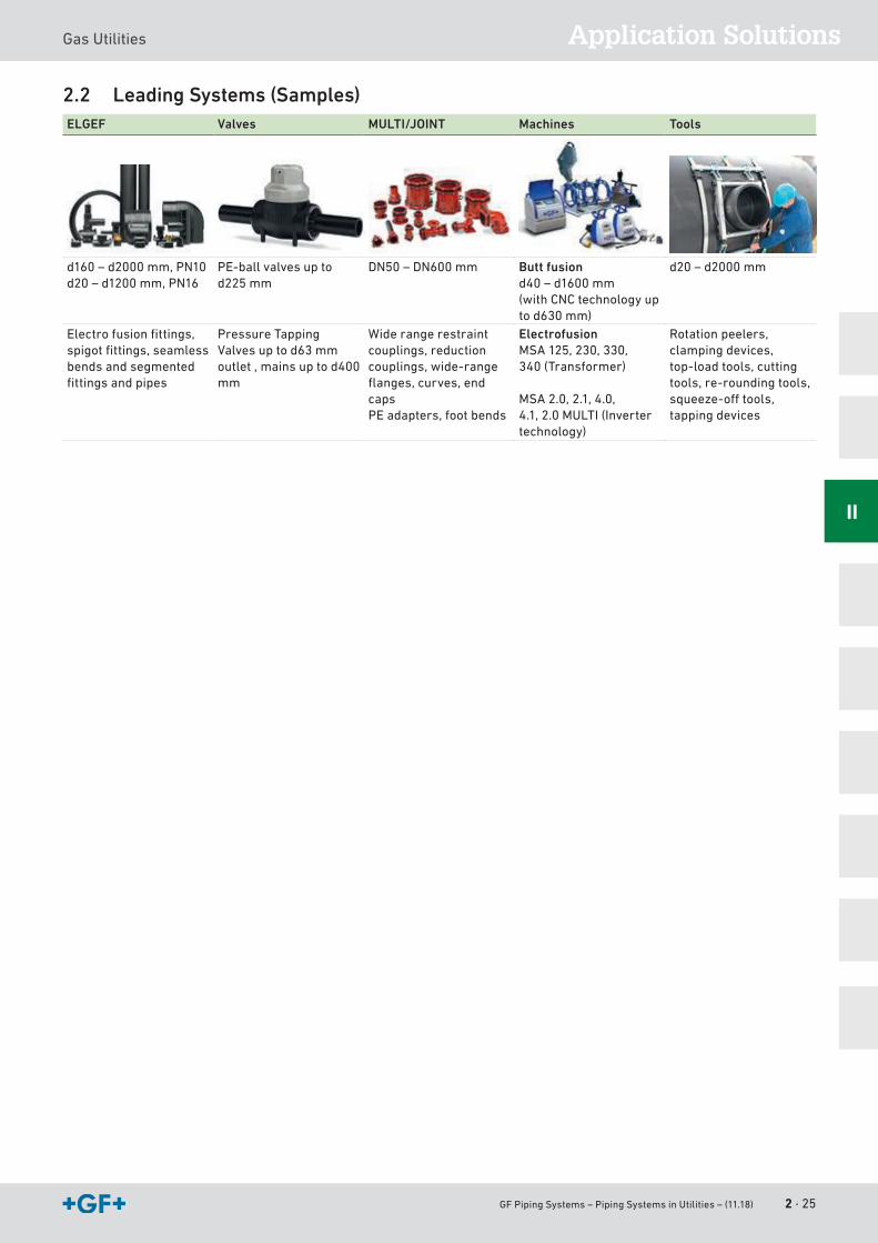
2.2 Leading Systems (Samples)ELGEF Valves MULTI/JOINT Machines Tools
d160–d2000mm,PN10d20–d1200mm,PN16
PE-ballvalvesuptod225mm
DN50–DN600mm Butt fusiond40–d1600mm(withCNCtechnologyuptod630mm)
d20–d2000mm
Electrofusionfittings,spigotfittings,seamlessbendsandsegmentedfittingsandpipes
PressureTappingValvesuptod63mmoutlet,mainsuptod400mm
Widerangerestraintcouplings,reductioncouplings,wide-rangeflanges,curves,endcaps PEadapters,footbends
ElectrofusionMSA125,230,330,340(Transformer)
MSA2.0,2.1,4.0,4.1,2.0MULTI(Invertertechnology)
Rotationpeelers,clampingdevices,top-loadtools,cuttingtools,re-roundingtools,squeeze-offtools,tappingdevices
2 · 26 GF Piping Systems – Piping Systems in Utilities – (11.18)
Automation
3 Automation
3.1 OverviewPEpipingsystemsarenotjustusedforsupplyinggasandwater,butincreasinglyalsoin
industrialapplications.
Beitformeasurement,controlorpropulsion,ourtechnologiesarenotonlyfullycompatible
withoneanother,but–regardlessoftheirdimensions–canalsobeseamlesslyintegrated
intoyourpipingsystemsusingsuitablesystemcomponentsfromGF PipingSystems.
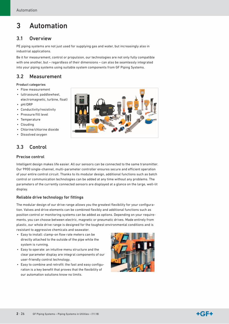
3.2 MeasurementProduct categories• Flowmeasurement
• (ultrasound,paddlewheel,
electromagnetic,turbine,float)
• pH/ORP
• Conductivity/resistivity
• Pressure/filllevel
• Temperature
• Clouding
• Chlorine/chlorinedioxide
• Dissolvedoxygen
3.3 Control
Precise control
Intelligentdesignmakeslifeeasier.Alloursensorscanbeconnectedtothesametransmitter.
Our9900single-channel,multi-parametercontrollerensuressecureandefficientoperation
ofyourentirecontrolcircuit.Thankstoitsmodulardesign,additionalfunctionssuchasbatch
controlorcommunicationtechnologiescanbeaddedatanytimewithoutanyproblems.The
parametersofthecurrentlyconnectedsensorsaredisplayedataglanceonthelarge,well-lit
display.
Reliable drive technology for fi ttings
Themodulardesignofourdriverangeallowsyouthegreatestflexibilityforyourconfigura-
tion.Valvesanddriveelementscanbecombinedflexiblyandadditionalfunctionssuchas
positioncontrolormonitoringsystemscanbeaddedasoptions.Dependingonyourrequire-
ments,youcanchoosebetweenelectric,magneticorpneumaticdrives.Madeentirelyfrom
plastic,ourwholedriverangeisdesignedforthetoughestenvironmentalconditionsandis
resistanttoaggressivechemicalsandseawater.• Easytoinstall:clamp-onflowratemeterscanbe
directlyattachedtotheoutsideofthepipewhilethe
systemisrunning.
• Easytooperate:anintuitivemenustructureandthe
clearparameterdisplayareintegralcomponentsofour
user-friendlycontroltechnology.
• Easytocombineandretrofit:thefastandeasyconfigu-
rationisakeybenefitthatprovesthattheflexibilityof
ourautomationsolutionsknownolimits.
GF Piping Systems – Piping Systems in Utilities –(11.18) 3 · 27
Plastic Piping Materials
Content
1 Properties of Plastic Piping Materials ...................................................................................281.1 Polyethylene (PE) . . . . . . . . . . . . . . . . . . . . . . . . . . . . . . . . . . . . . . . . . . . . . . . . . . . . . . . . . . . . . . . . . . . . . . . . . . . . . . . . . . . . . . . . . . . . . . . . . . . . . . . . . . . . . . . . . . . . . . . . . . . . . . . . . . . . . . . . . . . . . . . 28
1.2 Sustainability . . . . . . . . . . . . . . . . . . . . . . . . . . . . . . . . . . . . . . . . . . . . . . . . . . . . . . . . . . . . . . . . . . . . . . . . . . . . . . . . . . . . . . . . . . . . . . . . . . . . . . . . . . . . . . . . . . . . . . . . . . . . . . . . . . . . . . . . . . . . . . . . . . . . . . 30
2 Approvals and Standards ........................................................................................................332.1 Approvalsofproducts . . . . . . . . . . . . . . . . . . . . . . . . . . . . . . . . . . . . . . . . . . . . . . . . . . . . . . . . . . . . . . . . . . . . . . . . . . . . . . . . . . . . . . . . . . . . . . . . . . . . . . . . . . . . . . . . . . . . . . . . . . . . . . . . . . . . . . 33
2.2 Standardsandguidelines . . . . . . . . . . . . . . . . . . . . . . . . . . . . . . . . . . . . . . . . . . . . . . . . . . . . . . . . . . . . . . . . . . . . . . . . . . . . . . . . . . . . . . . . . . . . . . . . . . . . . . . . . . . . . . . . . . . . . . . . . . . . . . . . . 34 III
3 · 28 GF Piping Systems – Piping Systems in Utilities – (11.18)
PropertiesofPlasticPipingMaterials
1 Properties of Plastic Piping Materials
1.1 Polyethylene (PE)
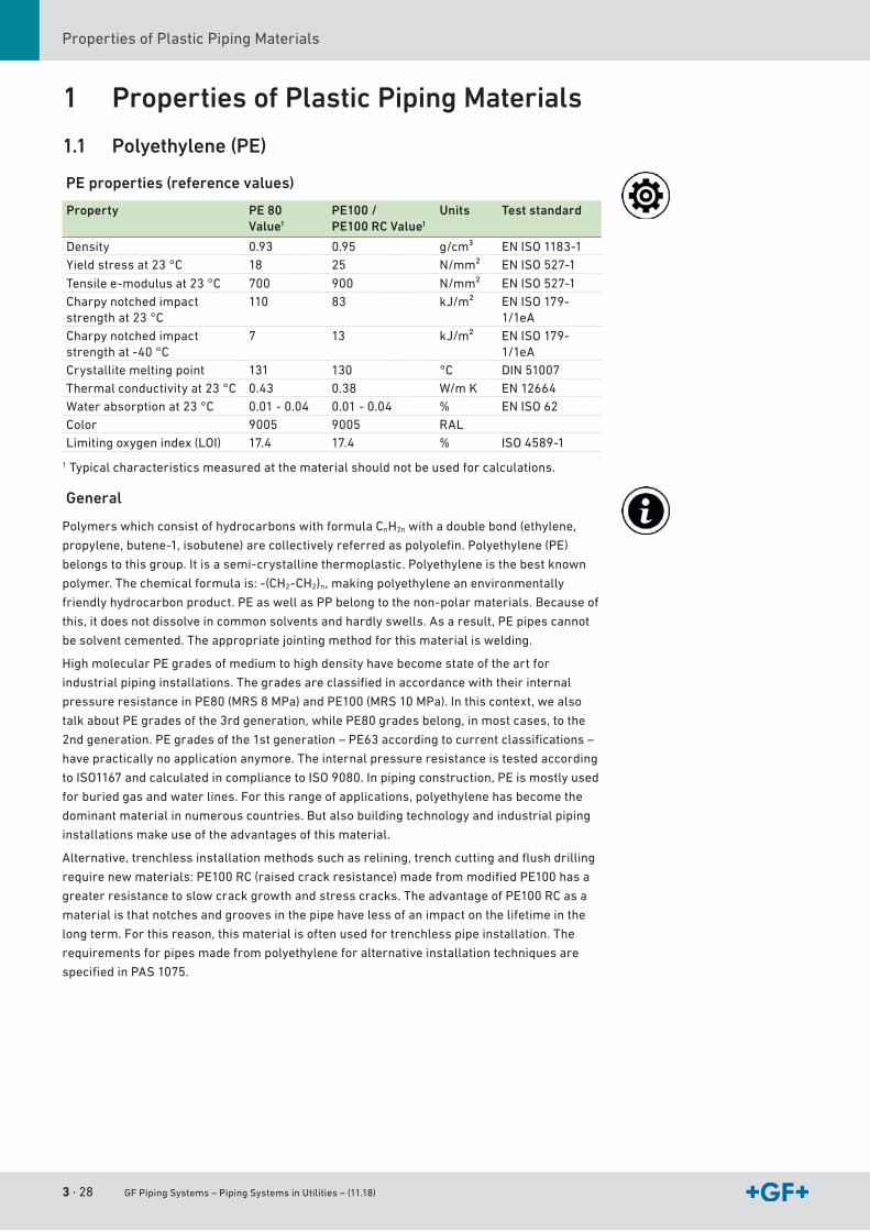
PE properties (reference values)
Property PE 80Value1
PE100 / PE100 RC Value1
Units Test standard
Density 0.93 0.95 g/cm³ EN ISO 1183-1Yieldstressat23°C 18 25 N/mm² ENISO527-1
Tensilee-modulusat23°C 700 900 N/mm² ENISO527-1Charpynotchedimpactstrengthat23°C
110 83 kJ/m² ENISO179-1/1eA
Charpynotchedimpactstrengthat-40°C
7 13 kJ/m² ENISO179-1/1eA
Crystallitemeltingpoint 131 130 °C DIN51007Thermalconductivityat23°C 0.43 0.38 W/m K EN12664Waterabsorptionat23°C 0.01 - 0.04 0.01 - 0.04 % ENISO62Color 9005 9005 RALLimitingoxygenindex(LOI) 17.4 17.4 % ISO 4589-1
1Typicalcharacteristicsmeasuredatthematerialshouldnotbeusedforcalculations.
General
PolymerswhichconsistofhydrocarbonswithformulaCnH2nwithadoublebond(ethylene,
propylene,butene-1,isobutene)arecollectivelyreferredaspolyolefin.Polyethylene(PE)
belongstothisgroup.Itisasemi-crystallinethermoplastic.Polyethyleneisthebestknown
polymer.Thechemicalformulais:-(CH2-CH2)n,makingpolyethyleneanenvironmentally
friendlyhydrocarbonproduct.PEaswellasPPbelongtothenon-polarmaterials.Becauseof
this,itdoesnotdissolveincommonsolventsandhardlyswells.Asaresult,PEpipescannot
besolventcemented.Theappropriatejointingmethodforthismaterialiswelding.
HighmolecularPEgradesofmediumtohighdensityhavebecomestateoftheartfor
industrialpipinginstallations.Thegradesareclassifiedinaccordancewiththeirinternal
pressureresistanceinPE80(MRS8MPa)andPE100(MRS10MPa).Inthiscontext,wealso
talkaboutPEgradesofthe3rdgeneration,whilePE80gradesbelong,inmostcases,tothe
2ndgeneration.PEgradesofthe1stgeneration–PE63accordingtocurrentclassifications–
havepracticallynoapplicationanymore.Theinternalpressureresistanceistestedaccording
toISO1167andcalculatedincompliancetoISO9080.Inpipingconstruction,PEismostlyused
forburiedgasandwaterlines.Forthisrangeofapplications,polyethylenehasbecomethe
dominantmaterialinnumerouscountries.Butalsobuildingtechnologyandindustrialpiping
installationsmakeuseoftheadvantagesofthismaterial.
Alternative,trenchlessinstallationmethodssuchasrelining,trenchcuttingandflushdrilling
requirenewmaterials:PE100RC(raisedcrackresistance)madefrommodifiedPE100hasa
greaterresistancetoslowcrackgrowthandstresscracks.TheadvantageofPE100RCasa
materialisthatnotchesandgroovesinthepipehavelessofanimpactonthelifetimeinthe
longterm.Forthisreason,thismaterialisoftenusedfortrenchlesspipeinstallation.The
requirementsforpipesmadefrompolyethyleneforalternativeinstallationtechniquesare
specifiedinPAS1075.
GF Piping Systems – Piping Systems in Utilities – (11.18) 3 · 29
Plastic Piping MaterialsPropertiesofPlasticPipingMaterials
III
Advantages of PE
• Lowweight
• Excellentflexibilityduringstorageandinstallationaswellasresistancetoearth
movements
• Goodabrasionresistance(abrasionresistance)
• Corrosionresistance,noadditionalmeasuresrequired
• Highimpactstrengthevenatlowtemperatures
• Goodchemicalresistance
• Smoothpipesurfaceresultinginhigherflowrate,lessincrustationandlowerenergycosts
• Suitablefortrenchlessinstallationtechniques
UV and weather resistance
Becauseoftheblackpigmentsused,blackpolyethyleneisveryweather-resistant.Even
longerexposuretodirectsunlight,windandrainhardlycausesanydamagetothematerial.
Chemical resistance
Polyethyleneshowsagoodresistanceagainstabroadrangeofmedia.Studiesby
independentinstituteshaveshownthattheexpectedlifetimeofPEpipes,evenunderextreme
conditions,exceedsthelifetimerequiredbystandards.Fordetailedinformation,observethe
listofchemicalresistancefromGF PipingSystemsorcontacttheresponsibleGF Piping
Systemsrepresentative.
Abrasion resistance
PEshowsexcellentresistancetoabrasivestress.Dependingonthesize,geometryandspeed
ofthesolidsbeingtransported,PEhasgreatadvantages,inparticularovermetallic
materials.PEpipingsystemsarethususedinmanyapplicationsfortransportingmediawith
solidcontents.
Application limits
Theapplicationlimitsofthematerialontheonehanddependonembrittlementandsoftening
temperaturesandontheotherhandonthenatureandtheexpectedservicelifeofthe
application.Thepressure-temperaturediagramsgivedetailsonapplicationtemperatures
andpressures.
Combustion behavior
Polyethylenebelongstotheflammableplastics.Theoxygenindexamountsto17%.Withan
oxygenindexbelow21%,aplasticmaterialisconsideredtobeflammable.PEdripsand
continuestoburnwithoutsootafterremovingtheflame.Basicallytoxicsubstancesare
releasedthroughallburningprocesses,particularlycarbonmonoxide.WhenPEburns,
primarilycarbondioxide,carbonmonoxideandwaterareformed.
Thefollowingclassificationsinaccordancewithdifferentcombustionstandardsareused:
• AccordingtoUL94,PEisclassifiedasHB(horizontalburning)andaccordingto
DIN53438-1asK2.
• AccordingtoDIN4102-1andEN13501-1,PEislistedasB2(normalflammable).
IntheFrenchclassificationofbuildingmaterials,polyethylenecorrespondstoM3(ofaverage
flammabilityrating).Theself-ignitiontemperatureis350°C.Suitablefire-fightingagentsare
water,foam,carbondioxideorpowder.
3 · 30 GF Piping Systems – Piping Systems in Utilities – (11.18)
PropertiesofPlasticPipingMaterials
Electrical properties
Likemostthermoplastics,polyethyleneisnon-conductive.Thismeansthatno
electrochemicalcorrosiontakesplaceinPEsystems.
However,thenon-conductivepropertieshavetobetakenintoaccountbecausean
electrostaticchargecanbuildupinthepipe.Polyethyleneprovidesgoodelectricalinsulation
properties.Thespecificvolumeresistanceis3.5x1016Ωcmandthespecificsurface
resistanceis1013Ω.Thesefigureshavetobetakenintoaccountwhereverthereisahazardof
ignitionorexplosion.
Physiological properties
TheblackpolyethylenematerialsfromGF PipingSystemsareauthorizedforuseinfood
applications.Theorganolepticpropertiesofthefittingsareinaccordancetotherelevant
standards.Usageinallrelatedareasisthuspossible.Fordetailsregardingexisting
approvalsforapplicationswithdrinkingwaterorfoodstuffs,pleasecontacttheresponsible
GF PipingSystemsrepresentative.
1.2 SustainabilityTheworldisfacingmajorchallengesintheenergysector.Thisincludestheincreasing
consumptionofenergy,thefinitenatureoffossilresources,theincreasingpricesforenergy
andclimatechange.Inordertosatisfytheneedsoftoday‘saswellasfuturegenerations,
sustainabledevelopmentisneeded.Plasticscontributetomasteringthesechallenges.
TheproductsofGF PipingSystemshavebeeninuseatcustomersformanyyears,insome
casesevendecades.Evenminorincreasesinefficiency–suchasthoseachievedbyasuitable
design–cansignificantlyinfluencetheenvironmentalbalance.Forthisreason,GF Piping
Systemspursuesacomprehensiveapproachinthedevelopmentofpipingsystems.
Sustainablesolutionsarepossibleonlyiftheentirelifeoftheapplicationsandproductsis
considered.
Plastics save energy
Besidestheirgenerallyknowntechnicaladvantages,suchascorrosionresistance,plastics
alsopresentecologicalbenefits.Withtheirlightweightandinsulatingeffect,plasticsare
suitableforanumberofenergy-efficientapplications:invehicles,forpackaging,in
insulationsandforpipingsystems.Plasticsareproducedprimarilyoutofcrudeoil.Roughly
fourpercentofthecrudeoilproducedworldwideisprocessedintoplastics.Effortstoreduce
theconsumptionofcrudeoilandotherfossilfuelsdonot,however,meananabandonmentof
plastics–onthecontrary:Energyissavedbyusingplastics!
Inastudy1,PlasticsEuropequantifiedwhattypeofeffectenergyconsumptionand
greenhouseemissionshavewhenplasticproductsweretobereplacedbyothermaterials.
The results of the study
• Productsmadeofplasticenablesignificantsavingsinenergyandgreenhouseemissions.
• Inmostcases,replacingplasticproductswithothermaterialsleadstoanincreaseof
energyconsumptionandgreenhouseemissions.
Ifasmanyplasticproductsaspossibleweretobereplacedwithothermaterials,morethan
50%moreenergywouldberequiredthantheenergycurrentlybeingconsumedduringthe
entirelifecycleofallplasticproducts.Inotherwords:Theplasticproductsthatarecurrently
onthemarkethaveenabledanenergysavingsof2,400millionGJperyear.Thisisthe
equivalentofanamountof50milliontonsofcrudeoilthatcouldbedistributedonto200very
largeoiltankers.
1 Pilz,H.,Brandt,B.,Fehrin-ger,R.(2010):Theimpactofplasticsonlifecycleenergyconsumptionandgreen-housegasemissionsinEuropeDenkstattGmbHundertheauthorityofPlasticsEurope,Brussels,Belgium.
GF Piping Systems – Piping Systems in Utilities – (11.18) 3 · 31
Plastic Piping MaterialsPropertiesofPlasticPipingMaterials
III
Life cycle assessment of pipes
GF PipingSystemshadalifecycleassessment2commissionedofpipesforbuilding
technology,industryandutilities.Inthisassessment,theenvironmentaleffectsofonemeter
ofpipeeacharecomparedfortheplasticsusedbyGF PipingSystemsandtheirmost
importantcompetingmaterials(forDN25,DN80,DN150andDN400).Thestudywascalculated
byindependentSwisslifecycleassessmentexpertsandisbasedontheinternationally
leadinglifecycleassessmentdatabase„Ecoinvent“.
TheresultisthatplasticpipesintheapplicationsanddimensionsdeliveredbyGF Piping
Systemsalmostalwaysshowbetterresultsthanthecompetingmaterials.Forexample,the
CO2footprint,i.e.thatistheaddedgreenhouseemissionsduringmanufacturing,transport
anddisposalofonemeterofPEpipeofdimensionDN80isroughlyfivetimeslowerthanfora
pipemadeofstainlesssteel.Decisivefactorsforthelifecycleassessmentofpipesarethe
typeandquantityofthematerialused.Foreverykilogramofmaterial,manyplasticsandalso
copperandstainlesssteelshowasimilarhighenergydemand.Low-alloyedsteelandcast
ironwithanaverageshareofregrindsaresignificantlylowerperkilogram.Theresultsdiffer
whenreferencedtoonemeterpipe.Basedonthesignificantlylowerweight,plasticpipesfare
verywellcomparedtometals,particularlyforthesmallandmediumdimensions.
PlasticpipesmadeofPEshowasignificantlybetterlifecycleassessmentthanmetalpipes.
Reducingmaterialdemandisatthecenteroffurtherimprovementofthelifecycle
assessmentofplasticpipes.Thisappliestoproductdevelopmentaswellastousersand
planners:
• Reducematerialdemandfurther
• Useofregrindsforpartswithlowloads
• Nooverdimensioningduringplanning(e.g.diameter,pressurelevel)
2 Büsser,S.,Frischknecht,R.(2008):Lifecycleassess-mentofpipes-comparisonofdifferentpipingmaterialsforbuildingservices,industryandutilities.ESU-ServicesLtd.onbehalfofGeorgFischerPipingSystems,UsterandSchaffhausen.
G3.1 Life cycle assessment of plastic pipes
3 · 32 GF Piping Systems – Piping Systems in Utilities – (11.18)
PropertiesofPlasticPipingMaterials
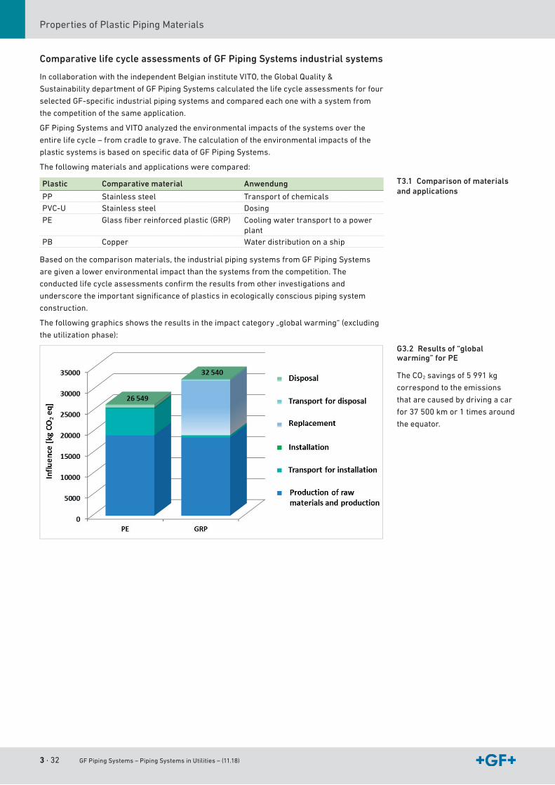
Comparative life cycle assessments of GF Piping Systems industrial systems
IncollaborationwiththeindependentBelgianinstituteVITO,theGlobalQuality&
SustainabilitydepartmentofGF PipingSystemscalculatedthelifecycleassessmentsforfour
selectedGF-specificindustrialpipingsystemsandcomparedeachonewithasystemfrom
thecompetitionofthesameapplication.
GF PipingSystemsandVITOanalyzedtheenvironmentalimpactsofthesystemsoverthe
entirelifecycle–fromcradletograve.Thecalculationoftheenvironmentalimpactsofthe
plasticsystemsisbasedonspecificdataofGF PipingSystems.
Thefollowingmaterialsandapplicationswerecompared:
Plastic Comparative material Anwendung
PP Stainlesssteel TransportofchemicalsPVC-U Stainlesssteel Dosing
PE Glassfiberreinforcedplastic(GRP) Coolingwatertransporttoapowerplant
PB Copper Waterdistributiononaship
Basedonthecomparisonmaterials,theindustrialpipingsystemsfromGF PipingSystems
aregivenalowerenvironmentalimpactthanthesystemsfromthecompetition.The
conductedlifecycleassessmentsconfirmtheresultsfromotherinvestigationsand
underscoretheimportantsignificanceofplasticsinecologicallyconsciouspipingsystem
construction.
Thefollowinggraphicsshowstheresultsintheimpactcategory„globalwarming“(excluding
theutilizationphase):
T3.1 Comparison of materials and applications
G3.2 Results of “global warming” for PE
TheCO2savingsof5 991 kg
correspondtotheemissions
thatarecausedbydrivingacar
for37 500 kmor1timesaround
theequator.
GF Piping Systems – Piping Systems in Utilities – (11.18) 3 · 33
Plastic Piping MaterialsApprovalsandStandards
III
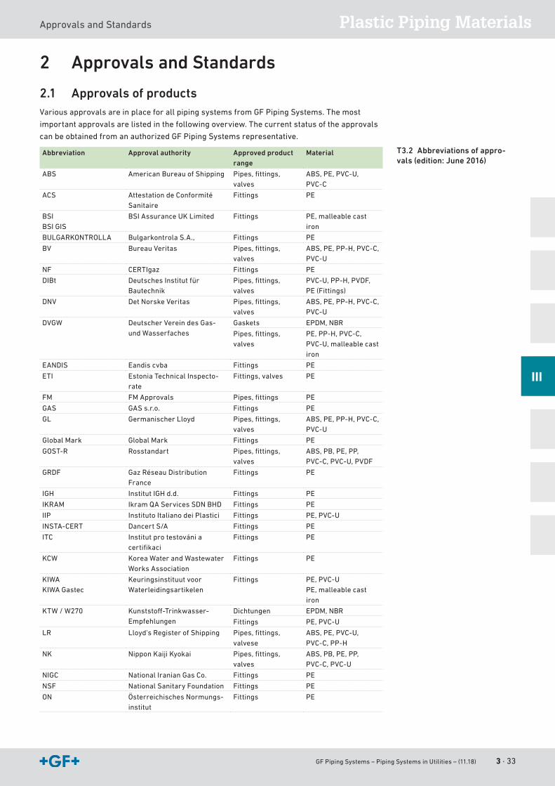
2 Approvals and Standards
2.1 Approvals of productsVariousapprovalsareinplaceforallpipingsystemsfromGF PipingSystems.Themost
importantapprovalsarelistedinthefollowingoverview.Thecurrentstatusoftheapprovals
canbeobtainedfromanauthorizedGF PipingSystemsrepresentative.
Abbreviation Approval authority Approved product range
Material
ABS AmericanBureauofShipping Pipes,fittings,valves
ABS,PE,PVC-U,PVC-C
ACS AttestationdeConformitéSanitaire
Fittings PE
BSI BSIGIS
BSIAssuranceUKLimited Fittings PE,malleablecastiron
BULGARKONTROLLA BulgarkontrolaS.A., Fittings PE
BV BureauVeritas Pipes,fittings,valves
ABS,PE,PP-H,PVC-C,PVC-U
NF CERTIgaz Fittings PE
DIBt DeutschesInstitutfürBautechnik
Pipes,fittings,valves
PVC-U,PP-H,PVDF,PE (Fittings)
DNV DetNorskeVeritas Pipes,fittings,valves
ABS,PE,PP-H,PVC-C,PVC-U
DVGW DeutscherVereindesGas-undWasserfaches
Gaskets EPDM,NBR
Pipes,fittings,valves
PE,PP-H,PVC-C,PVC-U,malleablecastiron
EANDIS Eandiscvba Fittings PE
ETI EstoniaTechnicalInspecto-rate
Fittings,valves PE
FM FMApprovals Pipes,fittings PE
GAS GASs.r.o. Fittings PE
GL GermanischerLloyd Pipes,fittings,valves
ABS,PE,PP-H,PVC-C,PVC-U
GlobalMark GlobalMark Fittings PE
GOST-R Rosstandart Pipes,fittings,valves
ABS,PB,PE,PP,PVC-C,PVC-U,PVDF
GRDF GazRéseauDistributionFrance
Fittings PE
IGH InstitutIGHd.d. Fittings PE
IKRAM IkramQAServicesSDNBHD Fittings PE
IIP InstitutoItalianodeiPlastici Fittings PE,PVC-U
INSTA-CERT DancertS/A Fittings PE
ITC Institutprotestovániacertifikaci
Fittings PE
KCW KoreaWaterandWastewaterWorksAssociation
Fittings PE
KIWAKIWAGastec
KeuringsinstituutvoorWaterleidingsartikelen
Fittings PE,PVC-UPE,malleablecastiron
KTW/W270 Kunststoff-Trinkwasser- Empfehlungen
Dichtungen EPDM,NBR
Fittings PE,PVC-U
LR Lloyd'sRegisterofShipping Pipes,fittings,valvese
ABS,PE,PVC-U,PVC-C,PP-H
NK NipponKaijiKyokai Pipes,fittings,valves
ABS,PB,PE,PP,PVC-C,PVC-U
NIGC NationalIranianGasCo. Fittings PE
NSF NationalSanitaryFoundation Fittings PE
ON ÖsterreichischesNormungs-institut
Fittings PE
T3.2 Abbreviations of appro-vals (edition: June 2016)
3 · 34 GF Piping Systems – Piping Systems in Utilities – (11.18)
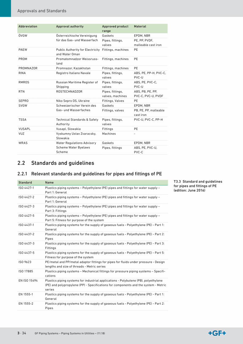
ApprovalsandStandards
Abbreviation Approval authority Approved product range
Material
ÖVGW ÖsterreichischeVereinigungfürdasGas-undWasserfach
Gaskets EPDM,NBR
Pipes,fittings,valves
PE,PP,PVDF,malleablecastiron
PAEW PublicAuthorityforElectricityandWaterOman
Fittings,machines PE
PROM PromatomnadzorWeissruss-land
Fittings,machines PE
PROMNAZOR Promnazor,Kazakhstan Fittings,machines PE
RINA RegistroItalianoNavale Pipes,fittings,valves
ABS,PE,PP-H,PVC-C,PVC-U
RMROS RussianMaritimeRegisterofShipping
Pipes,fittings,valves
ABS,PE,PVC-C,PVC-U
RTN ROSTECHNADZOR Pipes,fittings,valves,machines
ABS,PB,PE,PP,PVC-C,PVC-U,PVDF
SEPRO NikoSeproOS,Ukraine Fittings,Valves PE
SVGW SchweizerischerVereindesGas-undWasserfaches
Gaskets EPDM,NBR
Fittings,valves PB,PE,PP,malleablecastiron
TSSA TechnicalStandards&SafetyAuthority
Pipes,fittings,valves
PVC-U,PVC-C,PP-H
VUSAPL Vusapl,Slowakia Fittings PE
VUZ VyskumnyUstavZvaracsky,Slowakia
Machines -
WRAS WaterRegulationsAdvisorySchemeWaterByelawsScheme
Gaskets EPDM,NBR
Pipes,fittings ABS,PE,PVC-U,PVC-C
2.2 Standards and guidelines
2.2.1 Relevant standards and guidelines for pipes and fittings of PE
Standard Name
ISO4427-1 Plasticspipingsystems–Polyethylene(PE)pipesandfittingsforwatersupply–Part1:General
ISO4427-2 Plasticspipingsystems–Polyethylene(PE)pipesandfittingsforwatersupply–Part1:General
ISO4427-3 Plasticspipingsystems–Polyethylene(PE)pipesandfittingsforwatersupply–Part3:Fittings
ISO4427-5 Plasticspipingsystems–Polyethylene(PE)pipesandfittingsforwatersupply–Part5:Fitnessforpurposeofthesystem
ISO4437-1 Plasticspipingsystemsforthesupplyofgaseousfuels-Polyethylene(PE)-Part1:General
ISO4437-2 Plasticspipingsystemsforthesupplyofgaseousfuels-Polyethylene(PE)-Part2:Pipes
ISO4437-3 Plasticspipingsystemsforthesupplyofgaseousfuels-Polyethylene(PE)-Part3:Fittings
ISO4437-5 Plasticspipingsystemsforthesupplyofgaseousfuels-Polyethylene(PE)-Part5:Fitnessforpurposeofthesystem
ISO9623 PE/metalandPP/metaladaptorfittingsforpipesforfluidsunderpressure-Designlengthsandsizeofthreads-Metricseries
ISO17885 Plasticspipingsystems–Mechanicalfittingsforpressurepipingsystems–Specifi-cations
EN ISO 15494 Plasticspipingsystemsforindustrialapplications-Polybutene(PB),polyethylene(PE)andpolypropylene(PP)-Specificationsforcomponentsandthesystem-Metricseries
EN 1555-1 Plasticspipingsystemsforthesupplyofgaseousfuels-Polyethylene(PE)-Part1:General
EN1555-2 Plasticspipingsystemsforthesupplyofgaseousfuels-Polyethylene(PE)-Part2:Pipes
T3.3 Standard and guidelines for pipes and fittings of PE (edition: June 2016)
GF Piping Systems – Piping Systems in Utilities – (11.18) 3 · 35
Plastic Piping MaterialsApprovalsandStandards
III
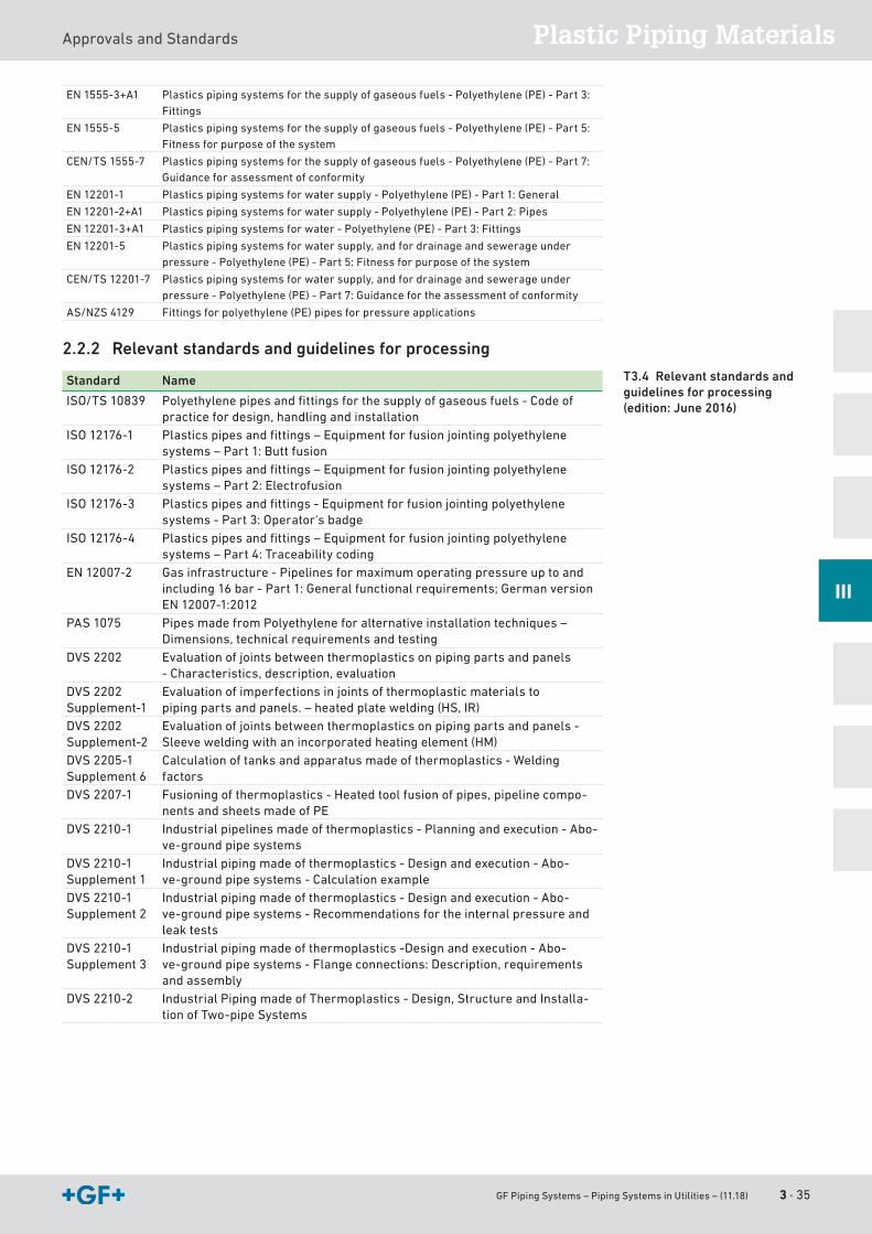
EN1555-3+A1 Plasticspipingsystemsforthesupplyofgaseousfuels-Polyethylene(PE)-Part3:Fittings
EN 1555-5 Plasticspipingsystemsforthesupplyofgaseousfuels-Polyethylene(PE)-Part5:Fitnessforpurposeofthesystem
CEN/TS1555-7 Plasticspipingsystemsforthesupplyofgaseousfuels-Polyethylene(PE)-Part7:Guidanceforassessmentofconformity
EN12201-1 Plasticspipingsystemsforwatersupply-Polyethylene(PE)-Part1:General
EN12201-2+A1 Plasticspipingsystemsforwatersupply-Polyethylene(PE)-Part2:Pipes
EN12201-3+A1 Plasticspipingsystemsforwater-Polyethylene(PE)-Part3:Fittings
EN12201-5 Plasticspipingsystemsforwatersupply,andfordrainageandsewerageunderpressure-Polyethylene(PE)-Part5:Fitnessforpurposeofthesystem
CEN/TS12201-7 Plasticspipingsystemsforwatersupply,andfordrainageandsewerageunderpressure-Polyethylene(PE)-Part7:Guidancefortheassessmentofconformity
AS/NZS4129 Fittingsforpolyethylene(PE)pipesforpressureapplications
2.2.2 Relevant standards and guidelines for processing
Standard Name
ISO/TS 10839 Polyethylenepipesandfittingsforthesupplyofgaseousfuels-Codeofpracticefordesign,handlingandinstallation
ISO12176-1 Plasticspipesandfittings–Equipmentforfusionjointingpolyethylenesystems–Part1:Buttfusion
ISO12176-2 Plasticspipesandfittings–Equipmentforfusionjointingpolyethylenesystems–Part2:Electrofusion
ISO12176-3 Plasticspipesandfittings-Equipmentforfusionjointingpolyethylenesystems-Part3:Operator‘sbadge
ISO12176-4 Plasticspipesandfittings–Equipmentforfusionjointingpolyethylenesystems–Part4:Traceabilitycoding
EN12007-2 Gasinfrastructure-Pipelinesformaximumoperatingpressureuptoandincluding16bar-Part1:Generalfunctionalrequirements;GermanversionEN12007-1:2012
PAS1075 PipesmadefromPolyethyleneforalternativeinstallationtechniques–Dimensions,technicalrequirementsandtesting
DVS2202 Evaluationofjointsbetweenthermoplasticsonpipingpartsandpanels-Characteristics,description,evaluation
DVS2202Supplement-1
Evaluationofimperfectionsinjointsofthermoplasticmaterialstopipingpartsandpanels.–heatedplatewelding(HS,IR)
DVS2202Supplement-2
Evaluationofjointsbetweenthermoplasticsonpipingpartsandpanels-Sleeveweldingwithanincorporatedheatingelement(HM)
DVS2205-1Supplement6
Calculationoftanksandapparatusmadeofthermoplastics-Weldingfactors
DVS2207-1 Fusioningofthermoplastics-Heatedtoolfusionofpipes,pipelinecompo-nentsandsheetsmadeofPE
DVS2210-1 Industrialpipelinesmadeofthermoplastics-Planningandexecution-Abo-ve-groundpipesystems
DVS2210-1Supplement1
Industrialpipingmadeofthermoplastics-Designandexecution-Abo-ve-groundpipesystems-Calculationexample
DVS2210-1Supplement2
Industrialpipingmadeofthermoplastics-Designandexecution-Abo-ve-groundpipesystems-Recommendationsfortheinternalpressureandleaktests
DVS2210-1Supplement3
Industrialpipingmadeofthermoplastics-Designandexecution-Abo-ve-groundpipesystems-Flangeconnections:Description,requirementsandassembly
DVS2210-2 IndustrialPipingmadeofThermoplastics -Design,StructureandInstalla-tionofTwo-pipeSystems
T3.4 Relevant standards and guidelines for processing (edition: June 2016)
3 · 36 GF Piping Systems – Piping Systems in Utilities – (11.18)
ApprovalsandStandards
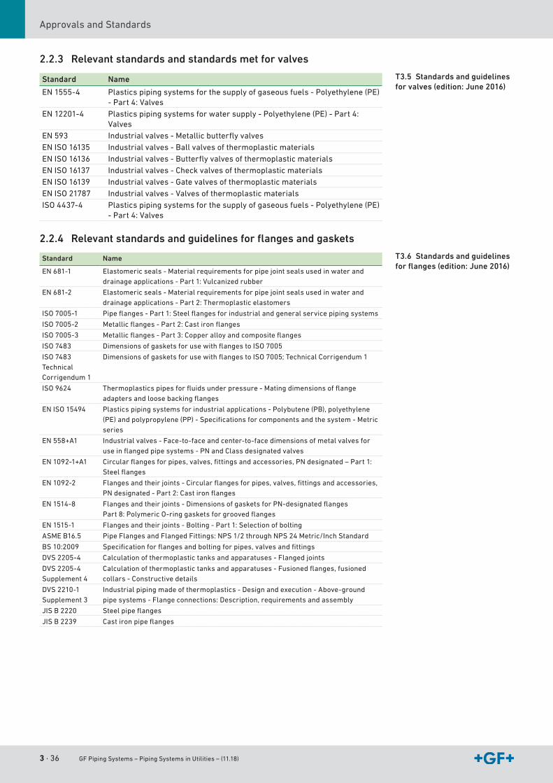
2.2.3 Relevant standards and standards met for valves
Standard Name
EN 1555-4 Plasticspipingsystemsforthesupplyofgaseousfuels-Polyethylene(PE)-Part4:Valves
EN12201-4 Plasticspipingsystemsforwatersupply-Polyethylene(PE)-Part4:Valves
EN 593 Industrialvalves-MetallicbutterflyvalvesENISO16135 Industrialvalves-BallvalvesofthermoplasticmaterialsENISO16136 Industrialvalves-ButterflyvalvesofthermoplasticmaterialsENISO16137 Industrialvalves-CheckvalvesofthermoplasticmaterialsENISO16139 Industrialvalves-GatevalvesofthermoplasticmaterialsENISO21787 Industrialvalves-ValvesofthermoplasticmaterialsISO4437-4 Plasticspipingsystemsforthesupplyofgaseousfuels-Polyethylene(PE)
-Part4:Valves
2.2.4 Relevant standards and guidelines for flanges and gaskets
Standard Name
EN681-1 Elastomericseals-Materialrequirementsforpipejointsealsusedinwateranddrainageapplications-Part1:Vulcanizedrubber
EN681-2 Elastomericseals-Materialrequirementsforpipejointsealsusedinwateranddrainageapplications-Part2:Thermoplasticelastomers
ISO7005-1 Pipeflanges-Part1:Steelflangesforindustrialandgeneralservicepipingsystems
ISO7005-2 Metallicflanges-Part2:Castironflanges
ISO7005-3 Metallicflanges-Part3:Copperalloyandcompositeflanges
ISO7483 DimensionsofgasketsforusewithflangestoISO7005
ISO7483TechnicalCorrigendum1
DimensionsofgasketsforusewithflangestoISO7005;TechnicalCorrigendum1
ISO9624 Thermoplasticspipesforfluidsunderpressure-Matingdimensionsofflangeadaptersandloosebackingflanges
EN ISO 15494 Plasticspipingsystemsforindustrialapplications-Polybutene(PB),polyethylene(PE)andpolypropylene(PP)-Specificationsforcomponentsandthesystem-Metricseries
EN558+A1 Industrialvalves-Face-to-faceandcenter-to-facedimensionsofmetalvalvesforuseinflangedpipesystems-PNandClassdesignatedvalves
EN1092-1+A1 Circularflangesforpipes,valves,fittingsandaccessories,PNdesignated–Part1:Steelflanges
EN1092-2 Flangesandtheirjoints-Circularflangesforpipes,valves,fittingsandaccessories,PNdesignated-Part2:Castironflanges
EN 1514-8 Flangesandtheirjoints-DimensionsofgasketsforPN-designatedflangesPart8:PolymericO-ringgasketsforgroovedflanges
EN 1515-1 Flangesandtheirjoints-Bolting-Part1:Selectionofbolting
ASMEB16.5 PipeFlangesandFlangedFittings:NPS1/2throughNPS24Metric/InchStandard
BS10:2009 Specificationforflangesandboltingforpipes,valvesandfittings
DVS2205-4 Calculationofthermoplastictanksandapparatuses-Flangedjoints
DVS2205-4Supplement4
Calculationofthermoplastictanksandapparatuses-Fusionedflanges,fusionedcollars-Constructivedetails
DVS2210-1Supplement3
Industrialpipingmadeofthermoplastics-Designandexecution-Above-groundpipesystems-Flangeconnections:Description,requirementsandassembly
JISB2220 Steelpipeflanges
JISB2239 Castironpipeflanges
T3.5 Standards and guidelines for valves (edition: June 2016)
T3.6 Standards and guidelines for flanges (edition: June 2016)
GF Piping Systems – Piping Systems in Utilities – (11.18) 3 · 37
Plastic Piping MaterialsApprovalsandStandards
III
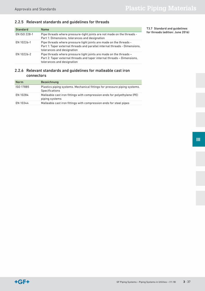
2.2.5 Relevant standards and guidelines for threads
Standard Name
ENISO228-1 Pipethreadswherepressure-tightjointsarenotmadeonthethreads-Part1:Dimensions,tolerancesanddesignation
EN10226-1 Pipethreadswherepressuretightjointsaremadeonthethreads- Part1:Taperexternalthreadsandparallelinternalthreads-Dimensions,tolerancesanddesignation
EN10226-2 Pipethreadswherepressuretightjointsaremadeonthethreads– Part2:Taperexternalthreadsandtaperinternalthreads–Dimensions,tolerancesanddesignation
2.2.6 Relevant standards and guidelines for malleable cast iron connectors
Norm Bezeichnung
ISO17885 Plasticspipingsystems.Mechanicalfittingsforpressurepipingsystems.Specifications
EN10284 Malleablecastironfittingswithcompressionendsforpolyethylene(PE)piping systems
EN 10344 Malleablecastironfittingswithcompressionendsforsteelpipes
T3.7 Standard and guidelines for threads (edition: June 2016)
3 · 38 GF Piping Systems – Piping Systems in Utilities – (11.18)
ApprovalsandStandards
GF Piping Systems – Piping Systems in Utilities – (11.18) 4 · 39
Design and Laying
Content
1 Basic knowledge ......................................................................................................................411.1 Metric and British system of units . . . . . . . . . . . . . . . . . . . . . . . . . . . . . . . . . . . . . . . . . . . . . . . . . . . . . . . . . . . . . . . . . . . . . . . . . . . . . . . . . . . . . . . . . . . . . . . . . . . . . . . . . . . . . . . . . . 41
1.2 Abbreviations and units of measure . . . . . . . . . . . . . . . . . . . . . . . . . . . . . . . . . . . . . . . . . . . . . . . . . . . . . . . . . . . . . . . . . . . . . . . . . . . . . . . . . . . . . . . . . . . . . . . . . . . . . . . . . . . . . . 42
1.3 SI-units . . . . . . . . . . . . . . . . . . . . . . . . . . . . . . . . . . . . . . . . . . . . . . . . . . . . . . . . . . . . . . . . . . . . . . . . . . . . . . . . . . . . . . . . . . . . . . . . . . . . . . . . . . . . . . . . . . . . . . . . . . . . . . . . . . . . . . . . . . . . . . . . . . . . . . . . . . . . . . . . 43
1.4 Conversion tables . . . . . . . . . . . . . . . . . . . . . . . . . . . . . . . . . . . . . . . . . . . . . . . . . . . . . . . . . . . . . . . . . . . . . . . . . . . . . . . . . . . . . . . . . . . . . . . . . . . . . . . . . . . . . . . . . . . . . . . . . . . . . . . . . . . . . . . . . . . . . . 45
2 Design .......................................................................................................................................462.1 Long-termbehaviorofthermoplasticmaterials . . . . . . . . . . . . . . . . . . . . . . . . . . . . . . . . . . . . . . . . . . . . . . . . . . . . . . . . . . . . . . . . . . . . . . . . . . . . . . . . . . . . . . . . . 46
2.2 Rangeofapplicationsforpipesandfittings . . . . . . . . . . . . . . . . . . . . . . . . . . . . . . . . . . . . . . . . . . . . . . . . . . . . . . . . . . . . . . . . . . . . . . . . . . . . . . . . . . . . . . . . . . . . . . . . . 50
2.3 Calculationofallowablepressure/requiredwallthickness . . . . . . . . . . . . . . . . . . . . . . . . . . . . . . . . . . . . . . . . . . . . . . . . . . . . . . . . . . . . . . . . . . . . . . 53
2.4 Water hammer . . . . . . . . . . . . . . . . . . . . . . . . . . . . . . . . . . . . . . . . . . . . . . . . . . . . . . . . . . . . . . . . . . . . . . . . . . . . . . . . . . . . . . . . . . . . . . . . . . . . . . . . . . . . . . . . . . . . . . . . . . . . . . . . . . . . . . . . . . . . . . . . . . . 55
2.5 Pipelines under vacuum . . . . . . . . . . . . . . . . . . . . . . . . . . . . . . . . . . . . . . . . . . . . . . . . . . . . . . . . . . . . . . . . . . . . . . . . . . . . . . . . . . . . . . . . . . . . . . . . . . . . . . . . . . . . . . . . . . . . . . . . . . . . . . . . . . . 59
3 Hydraulic Calcuation and Pressure Losses ...........................................................................653.1 Hydrauliccalculation. . . . . . . . . . . . . . . . . . . . . . . . . . . . . . . . . . . . . . . . . . . . . . . . . . . . . . . . . . . . . . . . . . . . . . . . . . . . . . . . . . . . . . . . . . . . . . . . . . . . . . . . . . . . . . . . . . . . . . . . . . . . . . . . . . . . . . . . . 65
3.2 Pressureloss . . . . . . . . . . . . . . . . . . . . . . . . . . . . . . . . . . . . . . . . . . . . . . . . . . . . . . . . . . . . . . . . . . . . . . . . . . . . . . . . . . . . . . . . . . . . . . . . . . . . . . . . . . . . . . . . . . . . . . . . . . . . . . . . . . . . . . . . . . . . . . . . . . . . . 70
4 Laying .......................................................................................................................................734.1 Pipe trenches . . . . . . . . . . . . . . . . . . . . . . . . . . . . . . . . . . . . . . . . . . . . . . . . . . . . . . . . . . . . . . . . . . . . . . . . . . . . . . . . . . . . . . . . . . . . . . . . . . . . . . . . . . . . . . . . . . . . . . . . . . . . . . . . . . . . . . . . . . . . . . . . . . . . . . 73
4.2 Trenchless laying . . . . . . . . . . . . . . . . . . . . . . . . . . . . . . . . . . . . . . . . . . . . . . . . . . . . . . . . . . . . . . . . . . . . . . . . . . . . . . . . . . . . . . . . . . . . . . . . . . . . . . . . . . . . . . . . . . . . . . . . . . . . . . . . . . . . . . . . . . . . . . . 74
4.3 Processingandhandling . . . . . . . . . . . . . . . . . . . . . . . . . . . . . . . . . . . . . . . . . . . . . . . . . . . . . . . . . . . . . . . . . . . . . . . . . . . . . . . . . . . . . . . . . . . . . . . . . . . . . . . . . . . . . . . . . . . . . . . . . . . . . . . . . . 74
4.4 Internalpressureandleaktest . . . . . . . . . . . . . . . . . . . . . . . . . . . . . . . . . . . . . . . . . . . . . . . . . . . . . . . . . . . . . . . . . . . . . . . . . . . . . . . . . . . . . . . . . . . . . . . . . . . . . . . . . . . . . . . . . . . . . . . 78
4.5 Disinfection of pipeline systems . . . . . . . . . . . . . . . . . . . . . . . . . . . . . . . . . . . . . . . . . . . . . . . . . . . . . . . . . . . . . . . . . . . . . . . . . . . . . . . . . . . . . . . . . . . . . . . . . . . . . . . . . . . . . . . . . . . . . 81
IV
4 · 40 GF Piping Systems – Piping Systems in Utilities – (11.18)
5 Jointing Technology .................................................................................................................825.1 Integralconnections . . . . . . . . . . . . . . . . . . . . . . . . . . . . . . . . . . . . . . . . . . . . . . . . . . . . . . . . . . . . . . . . . . . . . . . . . . . . . . . . . . . . . . . . . . . . . . . . . . . . . . . . . . . . . . . . . . . . . . . . . . . . . . . . . . . . . . . . . . 82
5.2 Butt fusion jointing (heating element fusion conventional butt fusion) . . . . . . . . . . . . . . . . . . . . . . . . . . . . . . . . . . . . . . . . . . . . . . . . . . . . 82
5.3 Electrofusion. . . . . . . . . . . . . . . . . . . . . . . . . . . . . . . . . . . . . . . . . . . . . . . . . . . . . . . . . . . . . . . . . . . . . . . . . . . . . . . . . . . . . . . . . . . . . . . . . . . . . . . . . . . . . . . . . . . . . . . . . . . . . . . . . . . . . . . . . . . . . . . . . . . . . . . 88
5.4 Basicinformationaboutweldingpreparation . . . . . . . . . . . . . . . . . . . . . . . . . . . . . . . . . . . . . . . . . . . . . . . . . . . . . . . . . . . . . . . . . . . . . . . . . . . . . . . . . . . . . . . . . . . . . . 89
5.5 Installationprocess . . . . . . . . . . . . . . . . . . . . . . . . . . . . . . . . . . . . . . . . . . . . . . . . . . . . . . . . . . . . . . . . . . . . . . . . . . . . . . . . . . . . . . . . . . . . . . . . . . . . . . . . . . . . . . . . . . . . . . . . . . . . . . . . . . . . . . . . . . . 93
5.6 CoolingtimesELGEFPluscoupler&fittings . . . . . . . . . . . . . . . . . . . . . . . . . . . . . . . . . . . . . . . . . . . . . . . . . . . . . . . . . . . . . . . . . . . . . . . . . . . . . . . . . . . . . . . . . . . . . . . . 95
5.7 CoolingtimesforELGEFPlussaddles&PVTs . . . . . . . . . . . . . . . . . . . . . . . . . . . . . . . . . . . . . . . . . . . . . . . . . . . . . . . . . . . . . . . . . . . . . . . . . . . . . . . . . . . . . . . . . . . . . 95
5.8 Mechanical joints . . . . . . . . . . . . . . . . . . . . . . . . . . . . . . . . . . . . . . . . . . . . . . . . . . . . . . . . . . . . . . . . . . . . . . . . . . . . . . . . . . . . . . . . . . . . . . . . . . . . . . . . . . . . . . . . . . . . . . . . . . . . . . . . . . . . . . . . . . . . . . . 96
5.9 Transitionadapterwiththread . . . . . . . . . . . . . . . . . . . . . . . . . . . . . . . . . . . . . . . . . . . . . . . . . . . . . . . . . . . . . . . . . . . . . . . . . . . . . . . . . . . . . . . . . . . . . . . . . . . . . . . . . . . . . . . . . . . . . . . . 97
5.10 Flange connections . . . . . . . . . . . . . . . . . . . . . . . . . . . . . . . . . . . . . . . . . . . . . . . . . . . . . . . . . . . . . . . . . . . . . . . . . . . . . . . . . . . . . . . . . . . . . . . . . . . . . . . . . . . . . . . . . . . . . . . . . . . . . . . . . . . . . . . . . . . 97
5.11 MULTI/JOINT3000Plus . . . . . . . . . . . . . . . . . . . . . . . . . . . . . . . . . . . . . . . . . . . . . . . . . . . . . . . . . . . . . . . . . . . . . . . . . . . . . . . . . . . . . . . . . . . . . . . . . . . . . . . . . . . . . . . . . . . . . . . . . . . . . . . . . . 105
5.12 iJOINT . . . . . . . . . . . . . . . . . . . . . . . . . . . . . . . . . . . . . . . . . . . . . . . . . . . . . . . . . . . . . . . . . . . . . . . . . . . . . . . . . . . . . . . . . . . . . . . . . . . . . . . . . . . . . . . . . . . . . . . . . . . . . . . . . . . . . . . . . . . . . . . . . . . . . . . . . . . . . . . . . 106
5.13 PRIMOFIT . . . . . . . . . . . . . . . . . . . . . . . . . . . . . . . . . . . . . . . . . . . . . . . . . . . . . . . . . . . . . . . . . . . . . . . . . . . . . . . . . . . . . . . . . . . . . . . . . . . . . . . . . . . . . . . . . . . . . . . . . . . . . . . . . . . . . . . . . . . . . . . . . . . . . . . . . . . 107
5.14 UNI-Coupling. . . . . . . . . . . . . . . . . . . . . . . . . . . . . . . . . . . . . . . . . . . . . . . . . . . . . . . . . . . . . . . . . . . . . . . . . . . . . . . . . . . . . . . . . . . . . . . . . . . . . . . . . . . . . . . . . . . . . . . . . . . . . . . . . . . . . . . . . . . . . . . . . . . . . 108
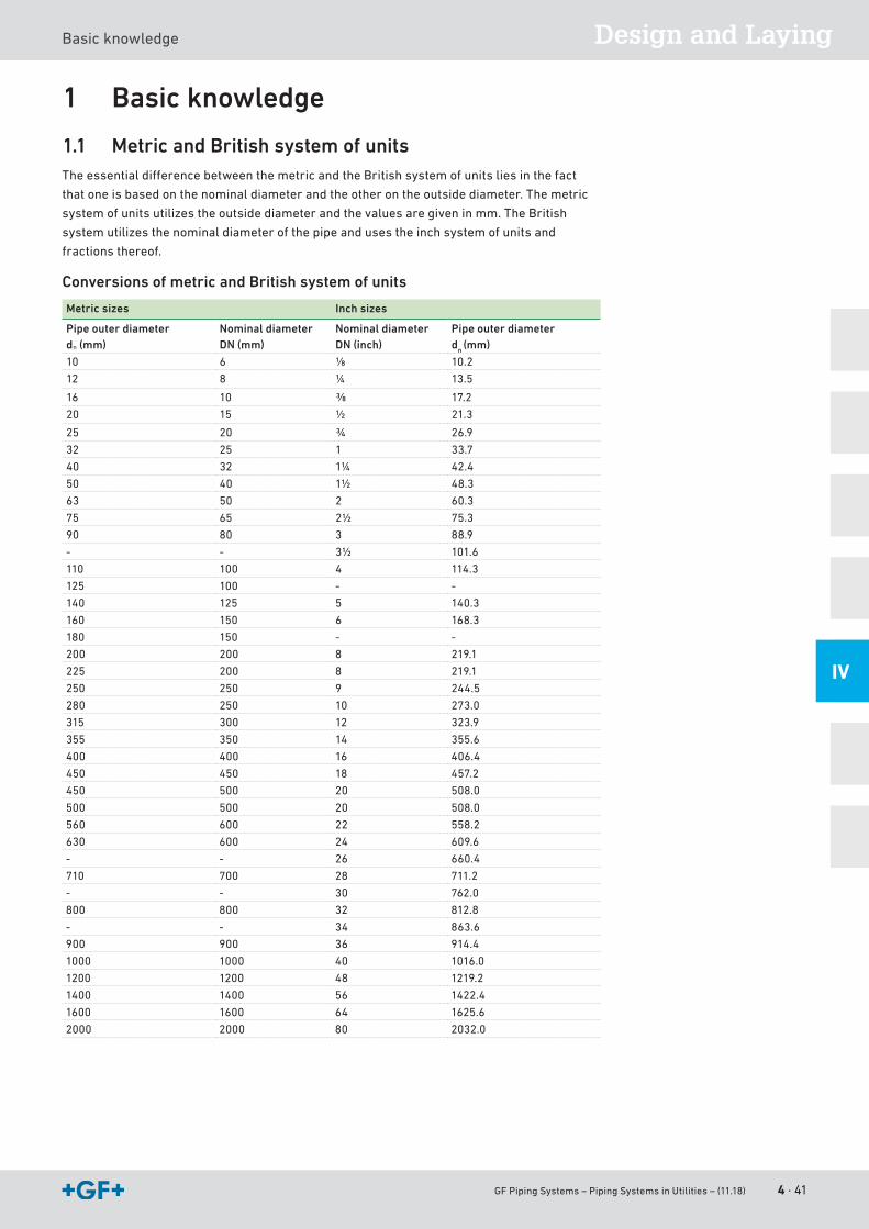
GF Piping Systems – Piping Systems in Utilities – (11.18) 4 · 41
Design and LayingBasicknowledge
IV
1 Basic knowledge
1.1 Metric and British system of unitsTheessentialdifferencebetweenthemetricandtheBritishsystemofunitsliesinthefact
that one is based on the nominal diameter and the other on the outside diameter. The metric
system of units utilizes the outside diameter and the values are given in mm. The British
system utilizes the nominal diameter of the pipe and uses the inch system of units and
fractions thereof.
Conversions of metric and British system of units
Metric sizes Inch sizes
Pipe outer diameterdn (mm)
Nominal diameterDN (mm)
Nominal diameterDN (inch)
Pipe outer diameterdn (mm)
10 6 ⅛ 10.2
12 8 ¼ 13.5
16 10 ⅜ 17.2
20 15 ½ 21.3
25 20 ¾ 26.9
32 25 1 33.7
40 32 1¼ 42.4
50 40 1½ 48.3
63 50 2 60.3
75 65 2½ 75.3
90 80 3 88.9
- - 3½ 101.6
110 100 4 114.3
125 100 - -
140 125 5 140.3
160 150 6 168.3
180 150 - -
200 200 8 219.1
225 200 8 219.1
250 250 9 244.5
280 250 10 273.0
315 300 12 323.9
355 350 14 355.6
400 400 16 406.4
450 450 18 457.2
450 500 20 508.0
500 500 20 508.0
560 600 22 558.2
630 600 24 609.6
- - 26 660.4
710 700 28 711.2
- - 30 762.0
800 800 32 812.8
- - 34 863.6
900 900 36 914.4
1000 1000 40 1016.0
1200 1200 48 1219.2
1400 1400 56 1422.4
1600 1600 64 1625.6
2000 2000 80 2032.0
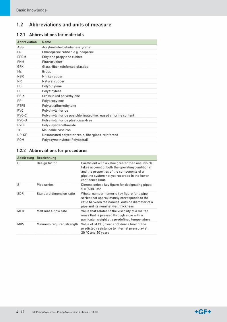
4 · 42 GF Piping Systems – Piping Systems in Utilities – (11.18)
Basicknowledge
1.2 Abbreviations and units of measure
1.2.1 Abbreviations for materials
Abbreviation Name
ABS Acrylonitrile-butadiene-styreneCR Chloroprene rubber, e.g. neoprene
EPDM Ethylenepropylenerubber
FKM Fluororubber
GFK Glass-fiberreinforcedplastics
Ms Brass
NBR Nitrilerubber
NR Naturalrubber
PB Polybutylene
PE Polyethylene
PE-X Crosslinkedpolyethylene
PP Polypropylene
PTFE Polytetrafluorethylene
PVC Polyvinylchloride
PVC-C Polyvinylchloride postchlorinated (increased chlorine content
PVC-U Polyvinylchlorideplasticizer-free
PVDF Polyvinylidenefluoride
TG Malleable cast iron
UP-GF Unsaturatedpolyesterresin,fiberglass-reinforced
POM Polyoxymethylene (Polyacetal)
1.2.2 Abbreviations for procedures
Abkürzung Bezeichnung
C Design factor Coefficientwithavaluegreaterthanone,whichtakesaccountofboththeoperatingconditionsand the properties of the components of a pipelinesystemnotyetrecordedinthelowerconfidencelimit.
S Pipe series Dimensionlesskeyfigurefordesignatingpipes; S=(SDR-1)/2
SDR Standard dimension ratio Whole-numbernumerickeyfigureforapipeseries that approximately corresponds to the ratiobetweenthenominaloutsidediameterofapipeanditsnominalwallthickness
MFR Meltmass-flowrate Valuethatrelatestotheviscosityofameltedmassthatispressedthroughadiewithaparticularweightatapredefinedtemperature
MRS Minimumrequiredstrength ValueofσLCL(lowerconfidencelimitofthepredicted resistance to internal pressure) at 20 °C and 50 years
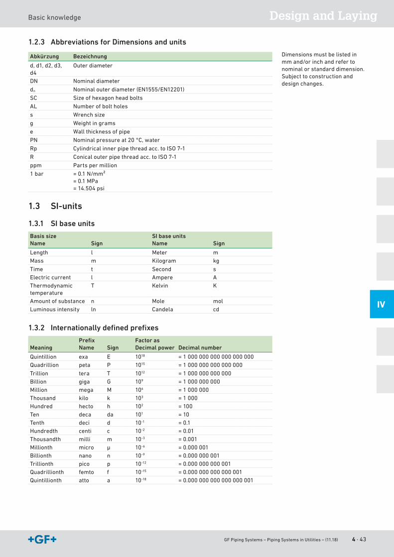
GF Piping Systems – Piping Systems in Utilities – (11.18) 4 · 43
Design and LayingBasicknowledge
IV
1.2.3 Abbreviations for Dimensions and units
Abkürzung Bezeichnung
d,d1,d2,d3,d4
Outerdiameter
DN Nominaldiameter
dn Nominalouterdiameter(EN1555/EN12201)
SC Size of hexagon head bolts
AL Numberofboltholes
s Wrench size
g Weight in grams
e Wallthicknessofpipe
PN Nominalpressureat20°C,water
Rp Cylindricalinnerpipethreadacc.toISO7-1
R Conicalouterpipethreadacc.toISO7-1
ppm Parts per million
1 bar =0.1N/mm²= 0.1 MPa= 14.504 psi
1.3 SI-units
1.3.1 SI base units
Basis sizeName Sign
SI base unitsName Sign
Length l Meter mMass m Kilogram kg
Time t Second sElectriccurrent l Ampere AThermodynamic temperature
T Kelvin K
Amount of substance n Mole molLuminous intensity ln Candela cd
1.3.2 Internationally defined prefixes
MeaningPrefixName Sign
Factor asDecimal power Decimal number
Quintillion exa E 1018 = 1 000 000 000 000 000 000Quadrillion peta P 1015 = 1 000 000 000 000 000
Trillion tera T 1012 = 1 000 000 000 000Billion giga G 109 = 1 000 000 000Million mega M 106 = 1 000 000Thousand kilo k 103 = 1 000Hundred hecto h 102 = 100Ten deca da 101 = 10Tenth deci d 10-1 = 0.1Hundredth centi c 10-2 = 0.01Thousandth milli m 10-3 = 0.001Millionth micro μ 10-6 = 0.000 001Billionth nano n 10-9 = 0.000 000 001Trillionth pico p 10-12 = 0.000 000 000 001Quadrillionth femto f 10-15 = 0.000 000 000 000 001Quintillionth atto a 10-18 = 0.000 000 000 000 000 001
Dimensions must be listed in mmand/orinchandrefertonominal or standard dimension. Subject to construction and design changes.
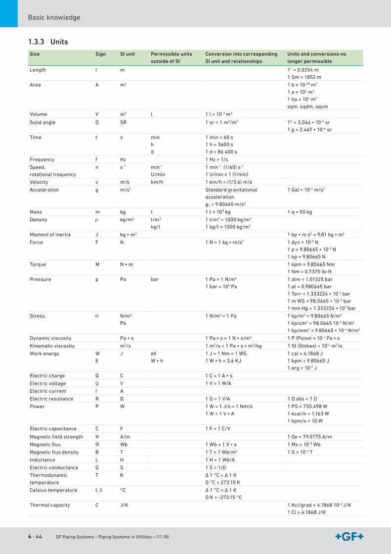
4 · 44 GF Piping Systems – Piping Systems in Utilities – (11.18)
Basicknowledge
1.3.3 Units
Size Sign SI unit Permissible units outside of SI
Conversion into corresponding SI unit and relationships
Units and conversions no longer permissible
Length I m 1” = 0.0254 m1 Sm = 1852 m
Area A m2 1 b = 10-28 m2
1 a = 102 m2
1 ha = 104 m2
sqm,sqdm,sqcm
Volume V m3 l 1 l = 10-3 m3
Solid angle Ω SR 1 sr = 1 m2/m2 1°=3.046•10-4 sr1g=2.467•10-4 sr
Time t s minhd
1 min = 60 s1h=3600s1 d = 86 400 s
Frequency f Hz 1Hz=1/s
Speed, rotationalfrequency
n s-1 min-1
U/min1 min-1(1/60)s-1
1U/min=1(1/min)
Velocity v m/s km/h 1km/h=(1/3.6)m/s
Acceleration g m/s2 Standard gravitational acceleration gn=9.80665m/s2
1 Gal = 10-2m/s2
Mass m kg t 1t=10³kg 1q=50kg
Density ρ kg/m3 t/m3 kg/l
1t/m3=1000kg/m3
1kg/l=1000kg/m3
Moment of inertia J kg•m2 1kp•ms2=9.81kg•m2
Force F N 1N=1kg•m/s2 1 dyn = 10-5N1p=9.80665•10-3N1kp=9.80665N
Torque M N•m 1kpm=9.80665Nm1Nm=0.7375lb-ft
Pressure p Pa bar 1Pa=1N/m2
1 bar = 105 Pa1atm=1.01325bar1at=0.980665bar1Torr=1.333224•10-3 bar1mWS=98.0665•10-3 bar1mmHg=1.333224•10-3bar
Stress σ N/m2 Pa
1N/m2 = 1 Pa 1kp/m2=9.80665N/m2
1kp/cm2=98.066510-3N/m2
1kp/mm2=9.80665•10-6N/m2
Dynamic viscosity Pa•s 1Pa•s=1N•s/m2 1 P (Poise) = 10-1Pa•s
Kinematic viscosity m2/s 1 m2/s=1Pa•s•m3/kg 1St(Stokes)=10-4 m2/s
Workenergy W E
J eVW•h
1J=1Nm=1WS1W•h=3.6KJ
1cal=4.1868J1kpm=9.80665J1 erg = 10-7J
Electriccharge Q C 1C=1A•s
Electricvoltage U V 1V=1W/A
Electriccurrent I A
Electricresistance R Ω 1Ω=1V/A 1Ωabs=1Ω
Power P W 1W=1J/s=1Nm/s 1W=1V•A
1PS=735.498W1kcal/h=1.163W1kpm/s=10W
Electriccapacitance C F 1F=1C/V
Magneticfieldstrength H A/m 1Oe=79.5775A/m
Magneticflux Φ Wb 1Wb=1V•s 1 Mx = 10-8 Wb
Magneticfluxdensity B T 1T=1Wb/m2 1 G = 10-4 T
Inductance L H 1H=1Wb/A
Electricconductance G S 1S=1/Ω
Thermodynamic temperature
T K Δ1°C=Δ1KO°C=273.15K
Celsius temperature t, δ °C Δ1°C=Δ1KOK=-273.15°C
Thermal capacity C J/K 1Kcl/grad=4.186810-3J/K1Cl=4.1868J/K
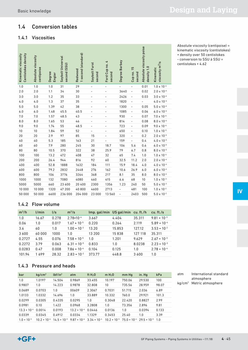
GF Piping Systems – Piping Systems in Utilities – (11.18) 4 · 45
Design and LayingBasicknowledge
IV
1.4 Conversion tables
1.4.1 Viscosities
Kin
emat
ic v
isco
sity
C
enti
stok
es d
ensi
ty
Abs
olut
e vi
scos
ity
cent
ipoi
se
Deg
ree
Eng
ler
Say
bolt
Uni
vers
al
seco
nd (S
SU
)
Red
woo
d
1 se
cond
(sta
ndar
d)
Say
bolt
Fur
ol
seco
nd
Ford
Cup
no.
4
seco
nd
Deg
ree
Bar
bey
Cup
no.
15
seco
nd
Abs
olut
e vi
scos
ity
pois
e de
nsit
y 1.
0
Kin
emat
ic
visc
osit
y m
²/s
1.0 1.0 1.0 31 29 - - - - 0.01 1.0 x 10⁻⁶
2.0 2.0 1.1 34 30 - - 3640 - 0.02 2.0 x 10⁻⁶
3.0 3.0 1.2 35 33 - - 2426 - 0.03 3.0x10⁻⁶
4.0 4.0 1.3 37 35 - - 1820 - - 4.0 x 10⁻⁶
5.0 5.0 1.39 42 38 - - 1300 - 0.05 5.0 x 10⁻⁶
6.0 6.0 1.48 45.5 40.5 - - 1085 - 0.06 6.0 x 10⁻⁶
7.0 7.0 1.57 48.5 43 - - 930 - 0.07 7.0 x 10⁻⁶
8.0 8.0 1.65 53 46 - - 814 - 0.08 8.0 x 10⁻⁶
9.0 9.0 1.74 55 48.5 - - 723 - 0.09 9.0x10⁻⁶
10 10 1.84 59 52 - - 650 - 0.10 1.0 x 10⁻⁵
20 20 2.9 97 85 15 - 320 - 0.2 2.0 x 10⁻⁵
40 40 5.3 185 163 21 - 159 - 0.4 4.0 x 10⁻⁵
60 60 7.9 280 245 30 18.7 106 5.6 0.6 6.0 x 10⁻⁵
80 80 10.5 370 322 38 25.9 79 6.7 0.8 8.0 x 10⁻⁵
100 100 13.2 472 408 47 32 65 7.4 1.0 1.0 x 10⁻⁴
200 200 26.4 944 816 92 60 32.5 11.2 2.0 2.0 x 10⁻⁴
400 400 52.8 1888 1632 184 111 15.9 18.4 4.0 4.0 x 10⁻⁴
600 600 79.2 2832 2448 276 162 10.6 26.9 6.0 6.0 x 10⁻⁴
800 800 106 3776 3264 368 217 8.1 35 8.0 8.0 x 10⁻⁴
1000 1000 132 7080 4080 460 415 6.6 68 10 1.0 x 10⁻³
5000 5000 660 23600 20 400 2300 1356 1.23 240 50 5.0 x 10⁻³
10 000 10 000 1320 47 200 40 800 4600 2713 - 481 100 1.0 x 10⁻²
50 000 50 000 6600 236000 204 000 23000 13560 - 2403 500 5.0 x 10⁻²
1.4.2 Flow volume
m3/h l/min l/s m3/s Imp. gal/min US gal/min cu. ft./h cu. ft./s
1.0 16.67 0.278 2.78•10-4 3.667 4.404 35.311 9.81•10-3
0.06 1.0 0.017 1.67•10-5 0.220 0.264 2.119 5.89•10-4
3.6 60 1.0 1.00•10-3 13.20 15.853 127.12 3.53•10-2
3600 60 000 1000 1.0 13200 15838 127 118 35.3110.2727 4.55 0.076 7.58•10-5 1.0 1.201 9.629 2.67•10-3
0.2272 3.79 0.063 6.31•10-5 0.833 1.0 8.0238 2.23•10-3
0.0283 0.47 0.008 7.86•10-6 0.104 0.125 1.0 2.78•10-4
101.94 1699 28.32 2.83•10-2 373.77 448.8 3600 1.0
1.4.3 Pressure and heads
bar kg/cm2 lbf/in2 atm ft H2O m H2O mm Hg in. Hg kPa
1.0 1.0197 14.504 0.9869 33.455 10.197 750.06 29.530 100
0.9807 1.0 14.223 0.9878 32.808 10 735.56 28.959 98.07
0.0689 0.0703 1.0 00609 2.3067 0.7031 51.715 2.036 6.89
1.0133 1.0332 14.696 1.0 33.889 10.332 760.0 29.921 101.3
0.0299 0.0305 0.4335 0.0295 1.0 0.3048 22.420 0.8827 2.99
0.0981 0.10 1.422 0.0968 3.2808 1.0 73.356 2.896 9.81
13.3•10-4 0.0014 0.0193 13.2•10-4 0.0446 0.0136 1.0 0.0394 0.133
0.0339 0.0345 0.4912 0.0334 1.1329 0.3453 25.40 1.0 3.39
1.0•10-5 10.2•10-6 14.5•10-5 9.87•10-6 3.34•10-4 10.2•10-5 75.0•10-4 29.5•10-5 1.0
Absolute viscosity (centipoise) = kinematicviscosity(centistokes)•densityover50centistokes-conversiontoSSUàSSU=centistokes•4.62
atm Internationalstandardatmosphere
kg/cm2 Metric atmosphere
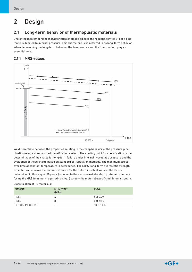
4 · 46 GF Piping Systems – Piping Systems in Utilities – (11.18)
Design
2 Design
2.1 Long-term behavior of thermoplastic materialsOneofthemostimportantcharacteristicsofplasticpipesistherealisticservicelifeofapipe
thatissubjectedtointernalpressure.Thischaracteristicisreferredtoaslong-termbehavior.
Whendeterminingthelong-termbehavior,thetemperatureandtheflowmediumplayan
essential role.
2.1.1 MRS-values
Wedifferentiatebetweenthepropertiesrelatingtothecreepbehaviorofthepressurepipe
plasticsusingastandardizedclassificationsystem.Thestartingpointforclassificationisthe
determinationofthechartsforlong-termfailureunderinternalhydrostaticpressureandthe
evaluation of these charts based on standard extrapolation methods. The maximum stress
overtimeatconstanttemperatureisdetermined.TheLTHS(long-termhydrostaticstrength)
expected value forms the theoretical curve for the determined test values. The stress
determinedinthiswayat50years(roundedtothenext-loweststandardpreferrednumber)
formstheMRS(minimumrequiredstrength)value–thematerial-specificminimumstrength.
ClassificationofPEmaterials:
Material MRS-Wert(MPa)
σLCL
PE63 6 6.3-7.99PE80 8 8.0-9.99
PE100/PE100RC 10 10.0-11.19
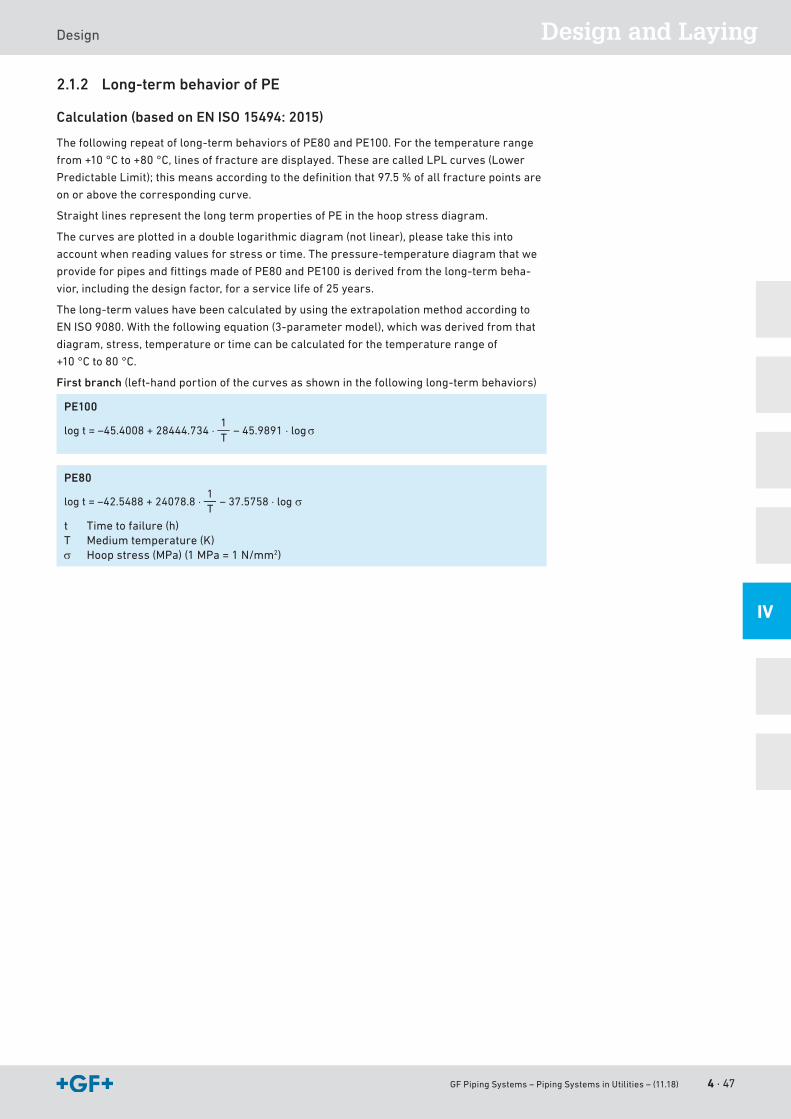
GF Piping Systems – Piping Systems in Utilities – (11.18) 4 · 47
Design and LayingDesign
IV
2.1.2 Long-term behavior of PE
Calculation (based on EN ISO 15494: 2015)
Thefollowingrepeatoflong-termbehaviorsofPE80andPE100.Forthetemperaturerange
from+10°Cto+80°C,linesoffracturearedisplayed.ThesearecalledLPLcurves(Lower
PredictableLimit);thismeansaccordingtothedefinitionthat97.5%ofallfracturepointsare
on or above the corresponding curve.
StraightlinesrepresentthelongtermpropertiesofPEinthehoopstressdiagram.
Thecurvesareplottedinadoublelogarithmicdiagram(notlinear),pleasetakethisinto
accountwhenreadingvaluesforstressortime.Thepressure-temperaturediagramthatwe
provideforpipesandfittingsmadeofPE80andPE100isderivedfromthelong-termbeha-
vior, including the design factor, for a service life of 25 years.
Thelong-termvalueshavebeencalculatedbyusingtheextrapolationmethodaccordingto
ENISO9080.Withthefollowingequation(3-parametermodel),whichwasderivedfromthat
diagram, stress, temperature or time can be calculated for the temperature range of
+10 °C to 80 °C.
First branch(left-handportionofthecurvesasshowninthefollowinglong-termbehaviors)
PE100
log t = –45.4008 + 28444.734 ⋅ – 45.9891 ⋅ log σ1T
PE80
log t = –42.5488 + 24078.8 ⋅ – 37.5758 ⋅ log σ1T
t Time to failure (h)T Medium temperature (K)σ Hoopstress(MPa)(1MPa=1N/mm2)
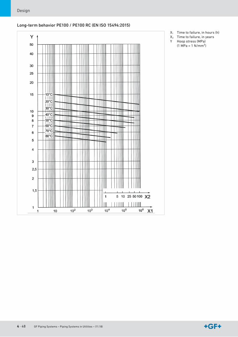
4 · 48 GF Piping Systems – Piping Systems in Utilities – (11.18)
Design
Long-term behavior PE100 / PE100 RC (EN ISO 15494:2015)
X1 Time to failure, in hours (h)X2 Time to failure, in yearsY Hoopstress(MPa)
(1MPa=1N/mm²)

GF Piping Systems – Piping Systems in Utilities – (11.18) 4 · 49
Design and LayingDesign
IV
Long-term behavior von PE80 (EN ISO 15494: 2015)
X1 Time to failure, in hours (h)X2 Time to failure, in yearsY Hoopstress(MPa)
(1MPa=1N/mm²)
4 · 50 GF Piping Systems – Piping Systems in Utilities – (11.18)
Design
2.2 Range of applications for pipes and fittings
2.2.1 In general
The choice of material and the pressure rating of the pipe components are important for both
operatingsafetyandforattainingthespecifiedminimumservicelifeofthesystem.
Thedecisiveinfluencingfactorsarethefollowing:
• Operatingpressure
• Operatingtemperature
• Medium transported
• Duration of stress
Separatecalculationsarenecessaryifdesignfactorsaredifferentortheservicelifeis
modified.Thesuitabilityofthematerialfortheflowmediumcanbedeterminedfromthelist
of chemical resistance provided separately by GF Piping Systems.
2.2.2 Pressure-temperature diagram for PE
PE100
APEsystemisdesignedbasedonaverageoperatingconditionstakingaccountofthe
maximumvalues.Incontrasttometalpipelines,PEpipelinesaredesignedwiththeaimofa
guaranteed life. The average operating conditions must be used as the basis for this.
If,forexample,alineisexposedtoatemperatureof40°Cforonemonthatthehottesttime,
this is not the temperature used as the basis for the calculation. A more accurate value is the
annual average temperature. As a result, the line is not overdimensioned and is instead
designedexactlytomeettheoperatingconditionrequirements.Thedesignfactors,described
later, provide additional reliability.
Thefollowingpressure-temperaturediagramforPE100pipesandfittingsisvalidfora
service life of 50 years.
Thedesignfactorof1.25forwaterand2.0forgashasbeenincorporated.
Thediagramcanbeusedforwaterormediaresemblingwater,inotherwords,mediathat
have no reduction factor for chemical resistance.
Please take into account the pressure-temperature diagrams for valves and special
fittings. Because of the construction and/or sealing material used, differences are
possible when compared to pipes and fittings. More information is available in the
Planning Fundamentals of the relevant types of valves and special fittings.
In case of long-term operating pressure at temperatures above 40 °C, please contact
your authorized GF Piping Systems representative.
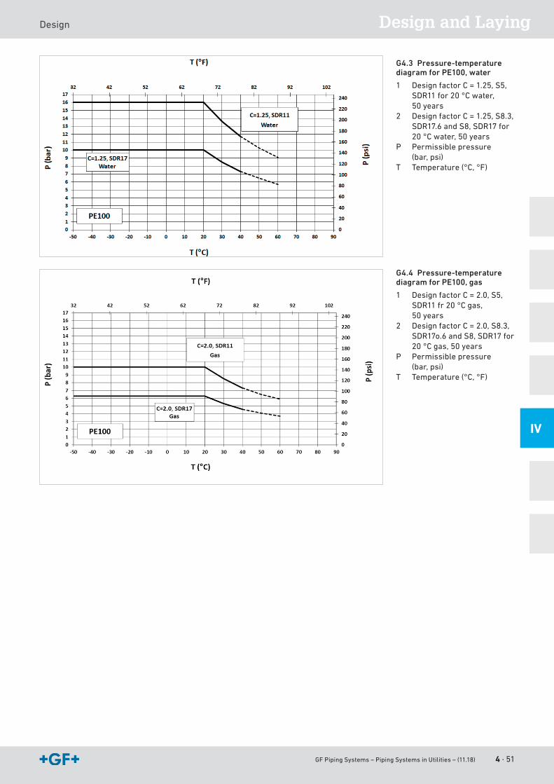
GF Piping Systems – Piping Systems in Utilities – (11.18) 4 · 51
Design and LayingDesign
IV
G4.3 Pressure-temperature diagram for PE100, water
1 Design factor C = 1.25, S5, SDR11for20°Cwater, 50 years
2 DesignfactorC=1.25,S8.3,SDR17.6 and S8, SDR17 for 20°Cwater,50years
P Permissible pressure (bar, psi)
T Temperature (°C, °F)
G4.4 Pressure-temperature diagram for PE100, gas
1 Design factor C = 2.0, S5, SDR11 fr 20 °C gas, 50 years
2 DesignfactorC=2.0,S8.3,SDR17o.6 and S8, SDR17 for 20 °C gas, 50 years
P Permissible pressure (bar, psi)
T Temperature (°C, °F)
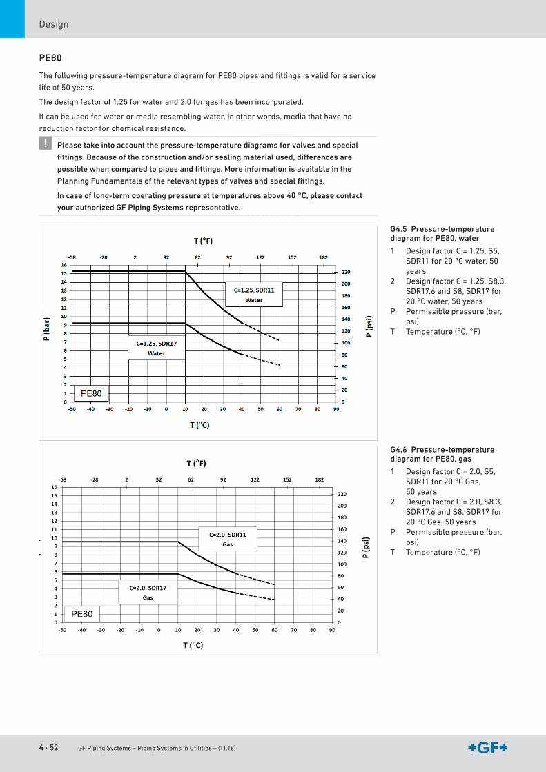
4 · 52 GF Piping Systems – Piping Systems in Utilities – (11.18)
Design
PE80
Thefollowingpressure-temperaturediagramforPE80pipesandfittingsisvalidforaservice
life of 50 years.
Thedesignfactorof1.25forwaterand2.0forgashasbeenincorporated.
Itcanbeusedforwaterormediaresemblingwater,inotherwords,mediathathaveno
reduction factor for chemical resistance.
Please take into account the pressure-temperature diagrams for valves and special
fittings. Because of the construction and/or sealing material used, differences are
possible when compared to pipes and fittings. More information is available in the
Planning Fundamentals of the relevant types of valves and special fittings.
In case of long-term operating pressure at temperatures above 40 °C, please contact
your authorized GF Piping Systems representative.
G4.5 Pressure-temperature diagram for PE80, water
1 Design factor C = 1.25, S5, SDR11for20°Cwater,50years
2 DesignfactorC=1.25,S8.3,SDR17.6 and S8, SDR17 for 20°Cwater,50years
P Permissible pressure (bar, psi)
T Temperature (°C, °F)
G4.6 Pressure-temperature diagram for PE80, gas
1 Design factor C = 2.0, S5, SDR11 for 20 °C Gas, 50 years
2 DesignfactorC=2.0,S8.3,SDR17.6 and S8, SDR17 for 20 °C Gas, 50 years
P Permissible pressure (bar, psi)
T Temperature (°C, °F)
GF Piping Systems – Piping Systems in Utilities – (11.18) 4 · 53
Design and LayingDesign
IV
2.3 Calculation of allowable pressure/required wall thickness
2.3.1 Selecting plastic piping components
Dimensioning of thermoplastic pipes subjected to internal pressure strictly adheres to
strengthrequirementsandiscalculatedbyusingthevesselformula.Allpipedimensions
listedinthestandardsarebasedonthisformula.Deviationsonlyoccurinthelowerrangeof
diameters,sincepracticalandmanufacturingconsiderationsmakeitnecessarytomaintain
certainminimumpipewallthicknesses.
e =p ⋅ d
20 ⋅ σzul + p
e Pipewallthickness(mm)d Pipe outer diameter (mm)p Permissible operating pressure (bar)σzul Allowablehoopstress(N/mm²)
Nominal pressure PN
Thedesignation„nominalpressure“PN(alsoknownaspressurelevel)byitselfisnolonger
sufficient.ThePNclassificationgenerallyusedallovertheworldasinformationforpipe
dimensioningisratherconfusingwherebuttfusionisconcerned.
Inthecaseofplasticpipesestablishedpracticeistousepressure-neutraldescriptionsfor
pipesofthesamepressurecapacity.Thisavoidsincorrectuseofpipesindifferentapplica-
tionsorunderdifferentconditions.
ISO4065classifiespipesbyseriesaccordingtopressurerating,sothatpipeswiththesame
series number have the same pressure rating, as is also the case in designations according to
nominal pressure levels. The pipe series are denoted by the letter S. The series designation is
basedonthefollowingformula:
S is a dimensionless value.
S =10 ⋅ σzul
p ⋅ C =
d – e2 ⋅ e
e Pipewallthickness(mm)d Pipe outer diameter (mm)p Operatingpressure(bar,psi)C Design factor
Hence,aPPpipewithdimensiond110andwallthickness=10mmresultsin:
S = = 5(110 – 10)
(2 ⋅ 10)
ThedesignationSDR(StandardDimensionRatio)ismuchmorecommononthemarket.SDR
indicatestheratioofoutsidediametertowallthickness.
SDR =de
ThepipeseriesdesignationandtheSDRdesignationareconnectedbythisformula:
SDR = 2 ⋅ S + 1
4 · 54 GF Piping Systems – Piping Systems in Utilities – (11.18)
Design
Inthecaseoftheexampleabove,thisresultsin:
SDR = 2 ⋅ 5 + 1 = 11
ThemarketprimarilyfeaturesthedesignationsPNandSDR.GFPipingSystemsrecommends
theuseofdimensionandwallthickness,aswellasSDRatalltimes.
2.3.2 Calculating the effective design factor / permissible operating pressure
Tocalculatethedesignfactorandallowableoperatingpressure,itisnecessarytoknowthe
long-termbehaviorofthematerial.Suchadiagramallowsthelong-termcreepstrengthtobe
readdependingonthedesiredservicelifeandoperatingtemperature.Forfittingsandvalves,
thewallthicknessisusuallygreaterthanforpipesofthesamepressurelevel.Forthis
reason,theoutsidediameterandwallthicknessofthepipeareusedtocalculatethedesign
factor.Thedesignfactoristhencalculatedbyusingthefollowingformula:
C =σs ⋅ 20 ⋅ e p ⋅ (d – e)
C Design factorσ Hoopstress(N/mm²)e Pipewallthickness(mm)d Pipe outer diameter (mm)p Operatingpressure(bar)
Similarly, the maximum permissible operating pressure is calculated by rewriting the formula above as:
20 ⋅ e ⋅ σs
Cp =
d – e
Example – Calculating the design factor and operating pressure
Intendedservicelife
Max. operating temperature
Max. operating pressure
Material
Intendedpressurelevel
Outsidediameter
Wallthickness
Hoopstress
50Jahre
+20 °C
10 bar
PE100
PN16bar
110 mm
10 mm
8.52N/mm2
C = = 2.0 > 1.2510 ⋅ 20 ⋅ 10 10 ⋅ (110 – 10)
Forthesakeofclarity,thecalculationsarecarriedoutusingtheexampleabove,but
usingtheusualminimumdesignfactorforPE100.
p = = 16 bar(110 – 10)
20 ⋅ 10 ⋅ 101.25
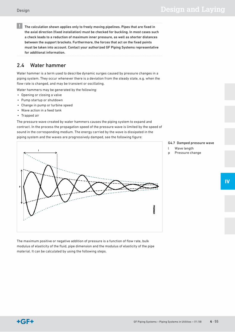
GF Piping Systems – Piping Systems in Utilities – (11.18) 4 · 55
Design and LayingDesign
IV
The calculation shown applies only to freely moving pipelines. Pipes that are fi xed in
the axial direction (fi xed installation) must be checked for buckling. In most cases such
a check leads to a reduction of maximum inner pressure, as well as shorter distances
between the support brackets. Furthermore, the forces that act on the fi xed points
must be taken into account. Contact your authorized GF Piping Systems representative
for additional information.
2.4 Water hammerWater hammer is a term used to describe dynamic surges caused by pressure changes in a
pipingsystem.Theyoccurwheneverthereisadeviationfromthesteadystate,e.g.whenthe
flowrateischanged,andmaybetransientoroscillating.
Waterhammersmaybegeneratedbythefollowing:
• Openingorclosingavalve
• Pumpstartuporshutdown
• Change in pump or turbine speed
• Waveactioninafeedtank
• Trapped air
Thepressurewavecreatedbywaterhammerscausesthepipingsystemtoexpandand
contract.Intheprocessthepropagationspeedofthepressurewaveislimitedbythespeedof
soundinthecorrespondingmedium.Theenergycarriedbythewaveisdissipatedinthe
pipingsystemandthewavesareprogressivelydamped,seethefollowingfigure:
Themaximumpositiveornegativeadditionofpressureisafunctionofflowrate,bulk
modulusofelasticityofthefluid,pipedimensionandthemodulusofelasticityofthepipe
material.Itcanbecalculatedbyusingthefollowingsteps.
G4.7 Damped pressure wave
l Wave lengthp Pressure change
4 · 56 GF Piping Systems – Piping Systems in Utilities – (11.18)
Design
a Determine the velocity of the pressure
Vw =K
ρ ⋅ 1 + K ⋅ di
e ⋅ EVw Velocityofpressurewave(m/s)K Bulkmodulusofelasticityoffluid(Pa)ρ Fluiddensity(kg/m³)E Modulusofelasticityofpipewall(Pa)di Innerdiameterofpipe(mm)e Pipewallthickness(mm)
Themodulusofelasticityofpipesmadeofthermoplasticpolymersvarieswiththeoperating
durationandtemperature.Hence,operatingdurationandtemperaturemustbeknownfora
precisecalculationofwaterhammers.
s Calculate maximum pressure change due to water hammers
∆p = Vw ⋅ ∆v ⋅ ρ / 10000
Δp Maximumpressurechange(bar)Vw Pressurewavevelocity(m/s)(seestep1)Δv Changeinfluidvelocity(m/s)=(v1-v2)v1 Velocityoffluidbeforechange(m/s)v2 Velocityoffluidafterchange(m/s)ρ Fluiddensity(kg/m³)
Allpressureincreasesinducedbyaflowreductionwillhaveacorrespondingpressuredrop
ontheotherside(vacuum).Ifthisexceedstheexpectedstaticminimumoperatingpressure,
thecalculatedpressuremustbecomparedtothepressureatwhichthepipecollapsesin
order to evaluate the safety factor in step 4.
d Calculate the maximum and minimum total pressure
pmax = p + ∆p
pmin = p – ∆p
pmax Maximum total pressure (bar)pmin Minimum total pressure (bar)p Expectedoperatingpressure(bar)Δp Changeduetowaterhammer(calculatedinstep2)
f Calculate the effective safety factor
Cmax =20 ⋅ σ ⋅ e
pmax ⋅ (d – e)
Cmax Safety factor (dimensionless)σ Circumferentialstress(N/mm²)t Pipethickness(mm)d Outsidediameterofpipe(mm)pmaxMaximumtotalpressure(bar)(calculatedinstep3)
Thevalueforthecircumferentialstresscanbefoundinthecreepcurves.Asmostwater
hammers last for a matter of seconds, the value for a load duration of 0.1 h can be used. The
exceptiontothisruleiswhenthewaterhammersareoscillating(e.g.fromapositivedispla-
cementpump).Inthiscasethesystemmustbetreatedasifaloadequaltothemaximumtotal
pressure (pmax) existed throughout the entire service life of the pipe.
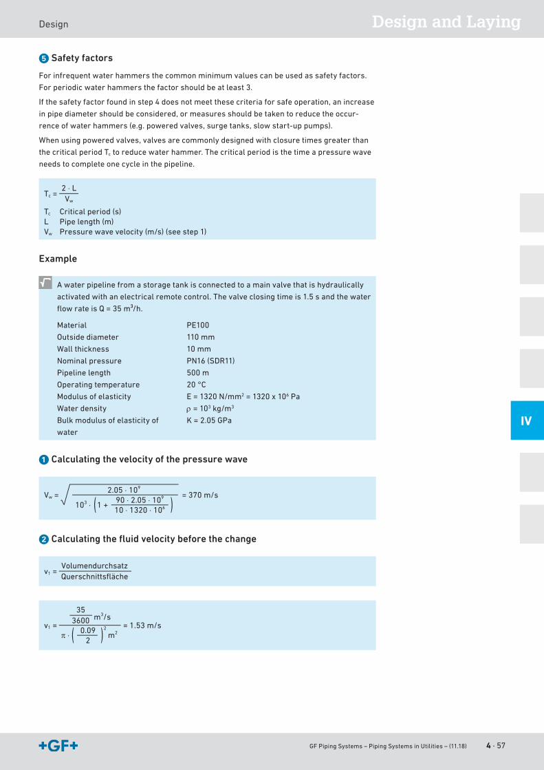
GF Piping Systems – Piping Systems in Utilities – (11.18) 4 · 57
Design and LayingDesign
IV
g Safety factors
Forinfrequentwaterhammersthecommonminimumvaluescanbeusedassafetyfactors.
Forperiodicwaterhammersthefactorshouldbeatleast3.
Ifthesafetyfactorfoundinstep4doesnotmeetthesecriteriaforsafeoperation,anincrease
inpipediametershouldbeconsidered,ormeasuresshouldbetakentoreducetheoccur-
renceofwaterhammers(e.g.poweredvalves,surgetanks,slowstart-uppumps).
Whenusingpoweredvalves,valvesarecommonlydesignedwithclosuretimesgreaterthan
the critical period Tctoreducewaterhammer.Thecriticalperiodisthetimeapressurewave
needs to complete one cycle in the pipeline.
Tc =2 ⋅ LVw
Tc Critical period (s)L Pipe length (m)Vw Pressurewavevelocity(m/s)(seestep1)
Example
Awaterpipelinefromastoragetankisconnectedtoamainvalvethatishydraulically
activatedwithanelectricalremotecontrol.Thevalveclosingtimeis1.5sandthewater
flowrateisQ=35m³/h.
Material
Outsidediameter
Wallthickness
Nominalpressure
Pipeline length
Operatingtemperature
Modulus of elasticity
Water density
Bulkmodulusofelasticityof
water
PE100
110 mm
10 mm
PN16(SDR11)
500 m
20 °C
E=1320N/mm2=1320x106 Pa
ρ = 103kg/m3
K = 2.05 GPa
a Calculating the velocity of the pressure wave
Vw = = 370 m/s2.05 ⋅ 109
103 ⋅ 1 + 90 ⋅ 2.05 ⋅ 109
10 ⋅ 1320 ⋅ 106
s Calculating the fluid velocity before the change
v1 =VolumendurchsatzQuerschnittsfläche
353600 m3/s
v1 =π ⋅ m20.09
2
2 = 1.53 m/s
4 · 58 GF Piping Systems – Piping Systems in Utilities – (11.18)
Design
Assumewatervelocitygoestozeroafterthevalveisclosed,i.e.Δv=1.53m/s.
Pressure change∆p = 370 ⋅ (1.53) ⋅ 1000/1000 = 5.65 bar
d Calculating the maximum pressure
pmax = 16 + 5.65 = 21.65 bar
Δpislessthenp.Hence,theminimumpressuredoesnothavetobetakenintoaccount.
f Calculating the circumferential stress
FindthecircumferentialstressinthePP-Hlong-termbehavior.Takethevalueforaload
durationof0.1has,fornon-oscillatingwaterhammers,thepipeneedstowithstandthisextra
pressure for only a matter of seconds.
σ=13.9N/mm2
C =20 ⋅ σ ⋅ e
pmax ⋅ (d – e)
C = = 1.2820 ⋅ 13.9 ⋅ 10
21.65 ⋅ (110 – 10)
g Calculating the maximum safety factor
TheminimumsafetyfactorforPE100canbesetto1.25.Here,C=1.28>1.2,sothispipingis
suitableforinfrequentwaterhammers.Howeveritwouldnotbesuitableifperiodicwater
hammersoccurred,becauseinthatcasewewouldneedC>3.Pipedimensionsorvalve
closingtimewouldneedtobeadjustedinordertoreducewaterhammer.
Calculating the critical period
Tc = = = 2.70 s2 ⋅ LVw
2 ⋅ 500 m370 m/s
Inthisexample,thevalveclosingtimeislessthanthevalueofthecriticalperiod.Byincrea-
singtheclosingtimeabovethiscriticalperiod,waterhammerwouldbereduced.Thepiping
wouldthenbesuitableforallsituationsinvolvingperiodicwatersurges.
GF Piping Systems – Piping Systems in Utilities – (11.18) 4 · 59
Design and LayingDesign
IV
2.5 Pipelines under vacuumThemechanicalloadatabsolutevacuumcorrespondstoadifferentialpartialvacuumof1bar,
i.e.theeffectivepressureonthepipe‘sinnerwallis1barlessthanthepressureontheouter
wallatstandardatmosphericpressure.
Incaseofadifferentialpartialvacuumspecialattentionmustbepaidtothedimensional
stabilityofthepipe.Itcanbecalculatedwiththeclassicbucklingformulaforcylindrical
pipes:
Pk = ⋅Ec
4 ⋅ (1 – µ2)er
3
Pk Criticalbucklingpressure(N/mm²)(1N/mm²=10bar)Ec Long-termcreepmodulus(N/mm²)μ Poisson‘sratioe Pipewallthickness(mm)r Mean pipe radius (mm)
Apipeatabsolutevacuum(differentialpartialvacuum1bar)isadequatelydimensioned
againstbucklingwhenthecriticalbucklingpressurePk=2bar,i.e.whenaminimumdesign
factorof2isusedforcalculation.Anyinfluencecausedbyout-of-roundnessandeccentricity
mustbetakenintoaccountseparately.Undertheseassumptions,thefollowingmaximum
applicationtemperaturesariseforthevariouspipematerials(takingintoaccountthegeneral
applicationtemperaturelimitsforthespecificmaterial),seethetablebelow.Thinner-walled
pipe series are unsuitable for these conditions.
(25yearvalues:Poisson‘sratioμ=0,4;designfactor=2)
2.5.1 Pipes and fittings
Maximum application temperatures under vacuum (1 bar differential partial vacuum)
Material PN(bar)
SDR Temperature(°C)
PE80 10 11 50PE100 / PE100 RC 16 11 60
2.5.2 Mechanical connections
Similartofittings,mechanicalconnectionsfeatureasignificantlygreaterwallthickness
comparedtopipes.However,thevacuumresistanceofthegasketsmustbeobserved.The
permissiblevacuumformechanicalconnectionsislistedinthefollowingtable:
Connection type Permissible vacuum (differential partial vacuum) (bar)
Union 1Threaded connection 1
Flangeconnection,flatgasket Notpossible
Flangeconnection,profileseal 1
Flangeconnection,O-ringseal 1
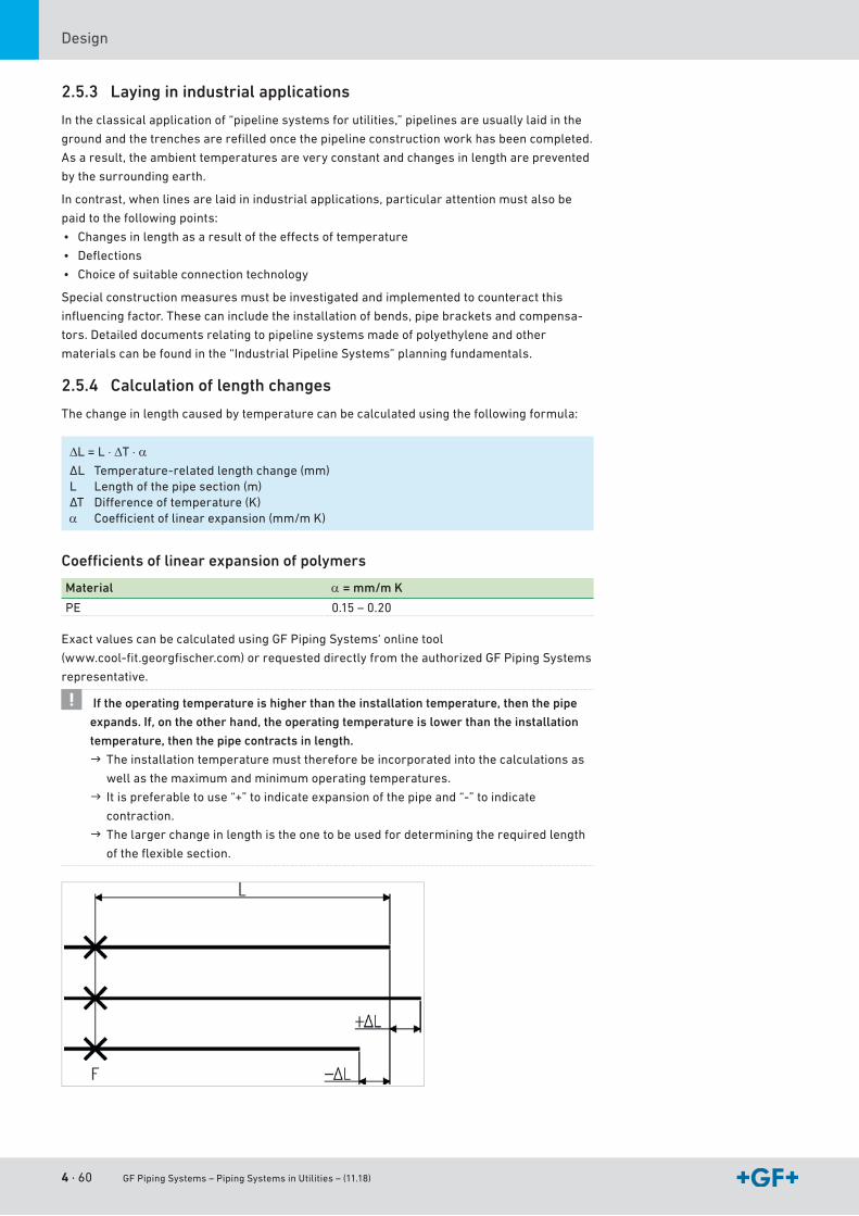
4 · 60 GF Piping Systems – Piping Systems in Utilities – (11.18)
Design
2.5.3 Laying in industrial applications
Intheclassicalapplicationof“pipelinesystemsforutilities,”pipelinesareusuallylaidinthe
groundandthetrenchesarerefilledoncethepipelineconstructionworkhasbeencompleted.
As a result, the ambient temperatures are very constant and changes in length are prevented
by the surrounding earth.
Incontrast,whenlinesarelaidinindustrialapplications,particularattentionmustalsobe
paidtothefollowingpoints:
• Changesinlengthasaresultoftheeffectsoftemperature
• Deflections
• Choice of suitable connection technology
Special construction measures must be investigated and implemented to counteract this
influencingfactor.Thesecanincludetheinstallationofbends,pipebracketsandcompensa-
tors. Detailed documents relating to pipeline systems made of polyethylene and other
materialscanbefoundinthe“IndustrialPipelineSystems”planningfundamentals.
2.5.4 Calculation of length changes
Thechangeinlengthcausedbytemperaturecanbecalculatedusingthefollowingformula:
∆L = L ⋅ ∆T ⋅ αΔL Temperature-relatedlengthchange(mm)L Length of the pipe section (m)ΔT Differenceoftemperature(K)α Coefficientoflinearexpansion(mm/mK)
Coeffi cients of linear expansion of polymers
Material α = mm/m K
PE 0.15 – 0.20
ExactvaluescanbecalculatedusingGFPipingSystems‘onlinetool
(www.cool-fit.georgfischer.com)orrequesteddirectlyfromtheauthorizedGFPipingSystems
representative.
If the operating temperature is higher than the installation temperature, then the pipe
expands. If, on the other hand, the operating temperature is lower than the installation
temperature, then the pipe contracts in length.
The installation temperature must therefore be incorporated into the calculations as
wellasthemaximumandminimumoperatingtemperatures.
Itispreferabletouse“+”toindicateexpansionofthepipeand“-”toindicate
contraction.
Thelargerchangeinlengthistheonetobeusedfordeterminingtherequiredlength
oftheflexiblesection.
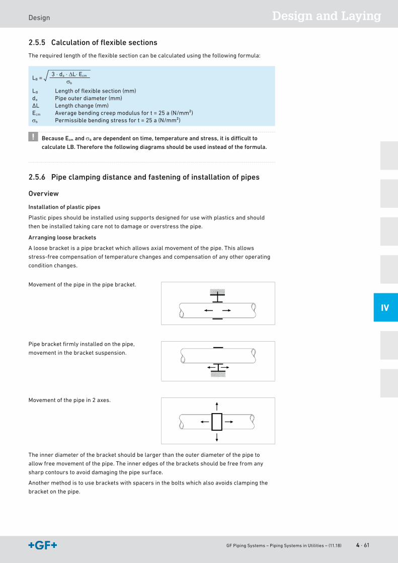
GF Piping Systems – Piping Systems in Utilities – (11.18) 4 · 61
Design and LayingDesign
IV
2.5.5 Calculation of flexible sections
Therequiredlengthoftheflexiblesectioncanbecalculatedusingthefollowingformula:
LB =3 ⋅ da ⋅ ∆L⋅ Ecm
σb
LB Lengthofflexiblesection(mm)da Pipe outer diameter (mm)ΔL Lengthchange(mm)Ecm Averagebendingcreepmodulusfort=25a(N/mm²)σb Permissiblebendingstressfort=25a(N/mm²)
Because Ecm and σb are dependent on time, temperature and stress, it is difficult to
calculate LB. Therefore the following diagrams should be used instead of the formula.
2.5.6 Pipe clamping distance and fastening of installation of pipes
Overview
Installation of plastic pipes
Plasticpipesshouldbeinstalledusingsupportsdesignedforusewithplasticsandshould
thenbeinstalledtakingcarenottodamageoroverstressthepipe.
Arranging loose brackets
Aloosebracketisapipebracketwhichallowsaxialmovementofthepipe.Thisallows
stress-freecompensationoftemperaturechangesandcompensationofanyotheroperating
condition changes.
Movementofthepipeinthepipebracket.
Pipebracketfirmlyinstalledonthepipe,
movementinthebracketsuspension.
Movement of the pipe in 2 axes.
Theinnerdiameterofthebracketshouldbelargerthantheouterdiameterofthepipeto
allowfreemovementofthepipe.Theinneredgesofthebracketsshouldbefreefromany
sharp contours to avoid damaging the pipe surface.
Anothermethodistousebracketswithspacersintheboltswhichalsoavoidsclampingthe
bracketonthepipe.
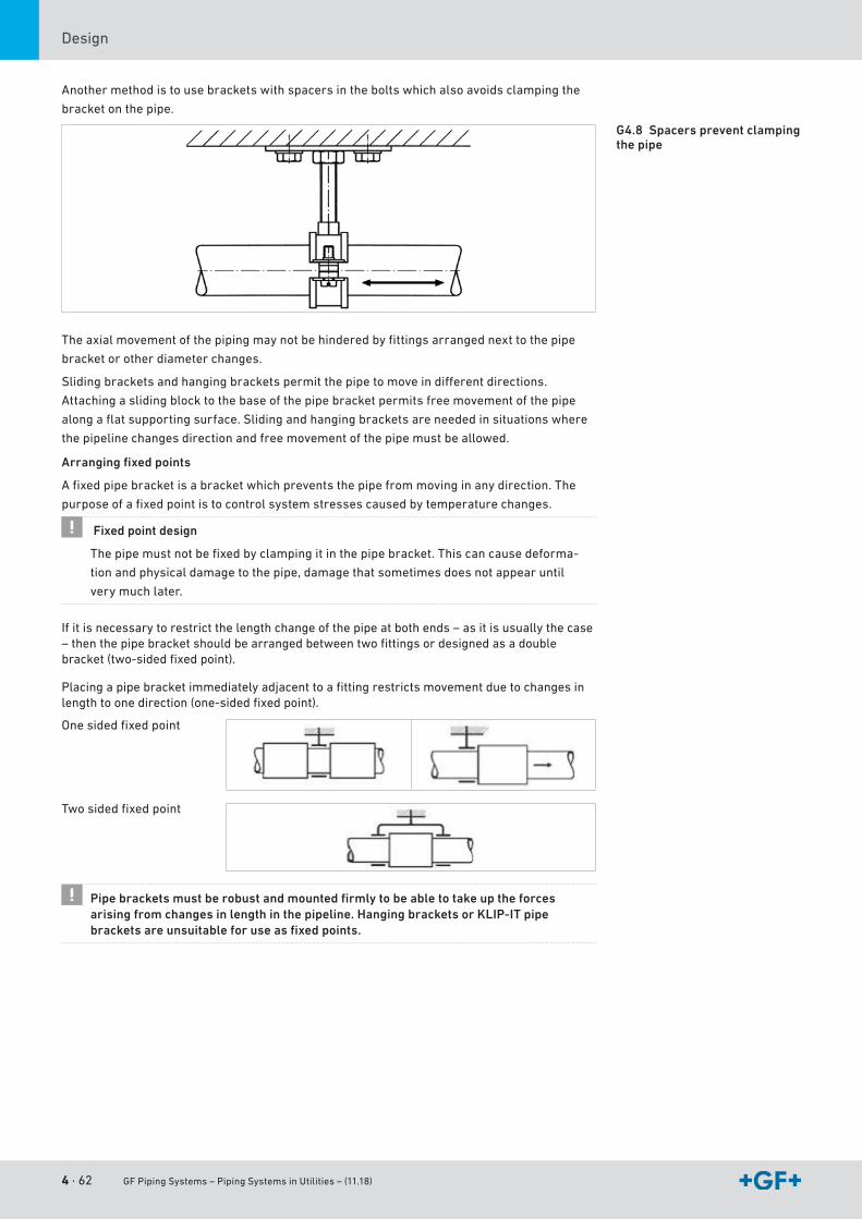
4 · 62 GF Piping Systems – Piping Systems in Utilities – (11.18)
Design
Anothermethodistousebracketswithspacersintheboltswhichalsoavoidsclampingthe
bracketonthepipe.
Theaxialmovementofthepipingmaynotbehinderedbyfittingsarrangednexttothepipe
bracketorotherdiameterchanges.
Slidingbracketsandhangingbracketspermitthepipetomoveindifferentdirections.
Attachingaslidingblocktothebaseofthepipebracketpermitsfreemovementofthepipe
alongaflatsupportingsurface.Slidingandhangingbracketsareneededinsituationswhere
thepipelinechangesdirectionandfreemovementofthepipemustbeallowed.
Arranging fixed points
Afixedpipebracketisabracketwhichpreventsthepipefrommovinginanydirection.The
purposeofafixedpointistocontrolsystemstressescausedbytemperaturechanges.
Fixed point design
Thepipemustnotbefixedbyclampingitinthepipebracket.Thiscancausedeforma-
tion and physical damage to the pipe, damage that sometimes does not appear until
very much later.
Ifitisnecessarytorestrictthelengthchangeofthepipeatbothends–asitisusuallythecase–thenthepipebracketshouldbearrangedbetweentwofittingsordesignedasadoublebracket(two-sidedfixedpoint).
Placingapipebracketimmediatelyadjacenttoafittingrestrictsmovementduetochangesinlengthtoonedirection(one-sidedfixedpoint).
Onesidedfixedpoint
Twosidedfixedpoint
Pipe brackets must be robust and mounted firmly to be able to take up the forces arising from changes in length in the pipeline. Hanging brackets or KLIP-IT pipe brackets are unsuitable for use as fixed points.
G4.8 Spacers prevent clamping the pipe
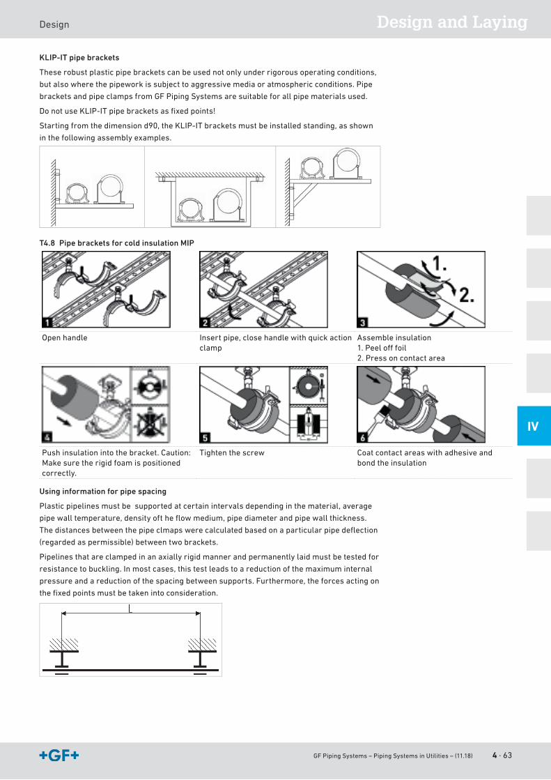
GF Piping Systems – Piping Systems in Utilities – (11.18) 4 · 63
Design and LayingDesign
IV
KLIP-IT pipe brackets
Theserobustplasticpipebracketscanbeusednotonlyunderrigorousoperatingconditions,
butalsowherethepipeworkissubjecttoaggressivemediaoratmosphericconditions.Pipe
bracketsandpipeclampsfromGFPipingSystemsaresuitableforallpipematerialsused.
DonotuseKLIP-ITpipebracketsasfixedpoints!
Startingfromthedimensiond90,theKLIP-ITbracketsmustbeinstalledstanding,asshown
inthefollowingassemblyexamples.
T4.8 Pipe brackets for cold insulation MIP
Openhandle Insertpipe,closehandlewithquickactionclamp
Assemble insulation1.Peelofffoil2. Press on contact area
Pushinsulationintothebracket.Caution:Makesuretherigidfoamispositionedcorrectly.
Tightenthescrew Coatcontactareaswithadhesiveandbond the insulation
Using information for pipe spacing
Plastic pipelines must be supported at certain intervals depending in the material, average
pipewalltemperature,densityoftheflowmedium,pipediameterandpipewallthickness.
Thedistancesbetweenthepipeclmapswerecalculatedbasedonaparticularpipedeflection
(regardedaspermissible)betweentwobrackets.
Pipelines that are clamped in an axially rigid manner and permanently laid must be tested for
resistancetobuckling.Inmostcases,thistestleadstoareductionofthemaximuminternal
pressureandareductionofthespacingbetweensupports.Furthermore,theforcesactingon
thefixedpointsmustbetakenintoconsideration.
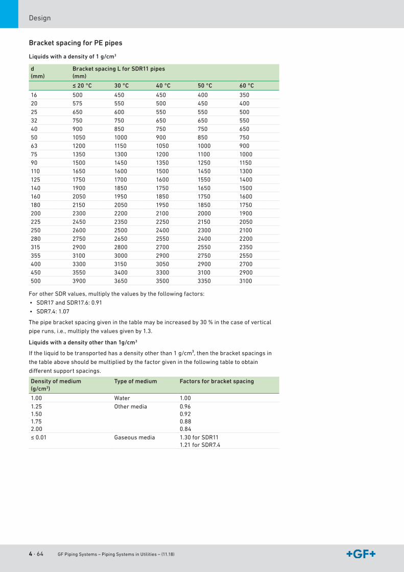
4 · 64 GF Piping Systems – Piping Systems in Utilities – (11.18)
Design
Bracket spacing for PE pipes
Liquids with a density of 1 g/cm3
d(mm)
Bracket spacing L for SDR11 pipes(mm)
≤ 20 °C 30 °C 40 °C 50 °C 60 °C
16 500 450 450 400 35020 575 550 500 450 400
25 650 600 550 550 50032 750 750 650 650 55040 900 850 750 750 65050 1050 1000 900 850 75063 1200 1150 1050 1000 90075 1350 1300 1200 1100 100090 1500 1450 1350 1250 1150110 1650 1600 1500 1450 1300125 1750 1700 1600 1550 1400140 1900 1850 1750 1650 1500160 2050 1950 1850 1750 1600180 2150 2050 1950 1850 1750200 2300 2200 2100 2000 1900225 2450 2350 2250 2150 2050250 2600 2500 2400 2300 2100280 2750 2650 2550 2400 2200315 2900 2800 2700 2550 2350355 3100 3000 2900 2750 2550400 3300 3150 3050 2900 2700450 3550 3400 3300 3100 2900500 3900 3650 3500 3350 3100
ForotherSDRvalues,multiplythevaluesbythefollowingfactors:
• SDR17andSDR17.6:0.91
• SDR7.4:1.07
Thepipebracketspacinggiveninthetablemaybeincreasedby30%inthecaseofvertical
piperuns,i.e.,multiplythevaluesgivenby1.3.
Liquids with a density other than 1g/cm3
Iftheliquidtobetransportedhasadensityotherthan1g/cm³,thenthebracketspacingsin
thetableaboveshouldbemultipliedbythefactorgiveninthefollowingtabletoobtain
differentsupportspacings.
Density of medium(g/cm3)
Type of medium Factors for bracket spacing
1.00 Water 1.001.251.501.752.00
Othermedia 0.960.920.880.84
≤0.01 Gaseous media 1.30forSDR111.21 for SDR7.4
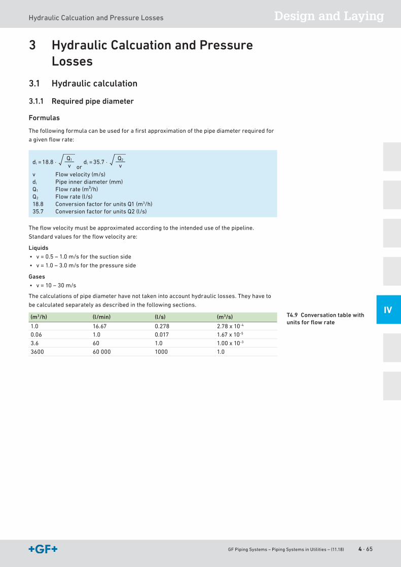
GF Piping Systems – Piping Systems in Utilities – (11.18) 4 · 65
Design and LayingHydraulicCalcuationandPressureLosses
IV
3 Hydraulic Calcuation and Pressure Losses
3.1 Hydraulic calculation
3.1.1 Required pipe diameter
Formulas
Thefollowingformulacanbeusedforafirstapproximationofthepipediameterrequiredfor
agivenflowrate:
18.8 ⋅di =Q1
v or 35.7 ⋅di =
Q2
v
v Flowvelocity(m/s)di Pipe inner diameter (mm)Q1 Flowrate(m³/h)Q2 Flowrate(l/s)18.8 Conversion factor for units Q1 (m3/h)35.7 ConversionfactorforunitsQ2(l/s)
Theflowvelocitymustbeapproximatedaccordingtotheintendeduseofthepipeline.
Standardvaluesfortheflowvelocityare:
Liquids
• v=0.5–1.0m/sforthesuctionside
• v=1.0–3.0m/sforthepressureside
Gases
• v=10–30m/s
Thecalculationsofpipediameterhavenottakenintoaccounthydrauliclosses.Theyhaveto
becalculatedseparatelyasdescribedinthefollowingsections.
(m3/h) (l/min) (l/s) (m3/s)
1.0 16.67 0.278 2.78 x 10⁻⁴
0.06 1.0 0.017 1.67 x 10⁻⁵
3.6 60 1.0 1.00 x 10⁻³
3600 60 000 1000 1.0
T4.9 Conversation table with units for flow rate
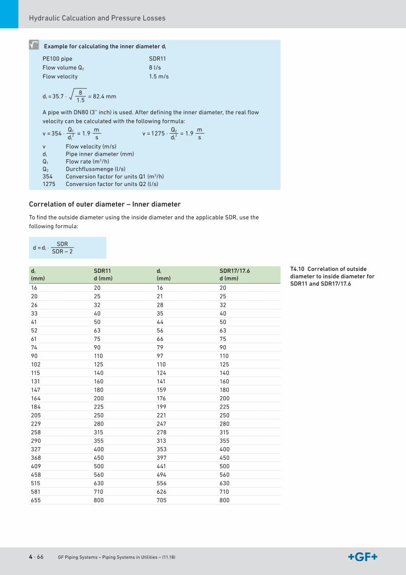
4 · 66 GF Piping Systems – Piping Systems in Utilities – (11.18)
HydraulicCalcuationandPressureLosses
Example for calculating the inner diameter di
PE100pipe
FlowvolumeQ2
Flowvelocity
SDR11
8l/s
1.5m/s
35.7 ⋅di = = 82.4 mm8
1.5
ApipewithDN80(3”inch)isused.Afterdefiningtheinnerdiameter,therealflow
velocitycanbecalculatedwiththefollowingformula:
354 ⋅v = = 1.9Q1
di2
ms
1275 ⋅v = = 1.9Q2
di2
ms
v Flowvelocity(m/s)di Pipe inner diameter (mm)Q1 Flowrate(m3/h)Q2 Durchflussmenge(l/s)354 ConversionfactorforunitsQ1(m3/h)1275 ConversionfactorforunitsQ2(l/s)
Correlation of outer diameter – Inner diameter
TofindtheoutsidediameterusingtheinsidediameterandtheapplicableSDR,usethe
followingformula:
di ⋅d =SDR
SDR – 2
di
(mm)SDR11d (mm)
di
(mm)SDR17/17.6d (mm)
16 20 16 2020 25 21 25
26 32 28 3233 40 35 4041 50 44 5052 63 56 6361 75 66 7574 90 79 9090 110 97 110102 125 110 125115 140 124 140131 160 141 160147 180 159 180164 200 176 200184 225 199 225205 250 221 250229 280 247 280258 315 278 315290 355 313 355327 400 353 400368 450 397 450409 500 441 500458 560 494 560515 630 556 630581 710 626 710655 800 705 800
T4.10 Correlation of outside diameter to inside diameter for SDR11 and SDR17/17.6
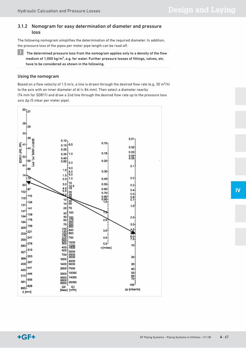
GF Piping Systems – Piping Systems in Utilities – (11.18) 4 · 67
Design and LayingHydraulicCalcuationandPressureLosses
IV
3.1.2 Nomogram for easy determination of diameter and pressure loss
Thefollowingnomogramsimplifiesthedeterminationoftherequireddiameter.Inaddition,
thepressurelossofthepipespermeterpipelengthcanbereadoff.
The determined pressure loss from the nomogram applies only to a density of the fl ow
medium of 1,000 kg/m³, e.g. for water. Further pressure losses of fi ttings, valves, etc.
have to be considered as shown in the following.
Using the nomogram
Basedonaflowvelocityof1.5m/s,alineisdrawnthroughthedesiredflowrate(e.g.30m³/h)
totheaxiswithaninnerdiameterofdi(≈84mm).Thenselectadiameternearby
(74mmforSDR11)anddrawa2ndlinethroughthedesiredflowrateuptothepressureloss
axisΔp(5mbarpermeterpipe).
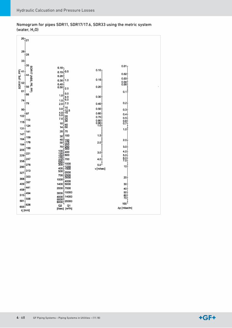
4 · 68 GF Piping Systems – Piping Systems in Utilities – (11.18)
HydraulicCalcuationandPressureLosses
Nomogram for pipes SDR11, SDR17/17.6, SDR33 using the metric system (water, H2O)
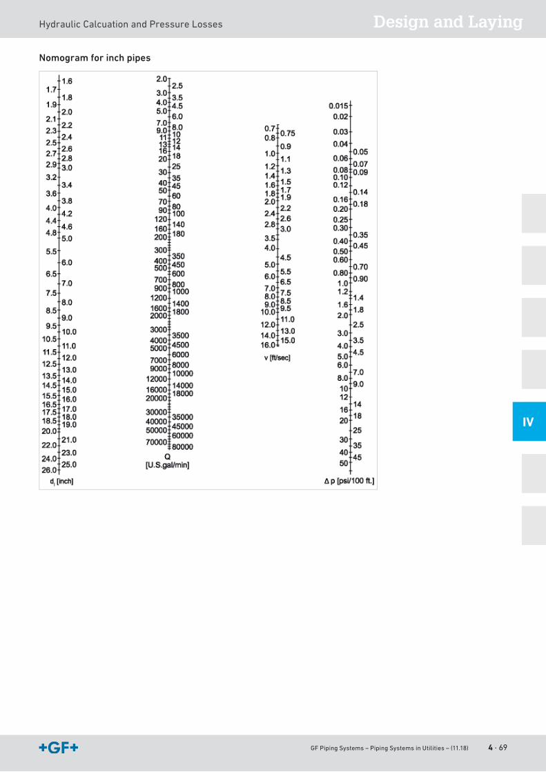
GF Piping Systems – Piping Systems in Utilities – (11.18) 4 · 69
Design and LayingHydraulicCalcuationandPressureLosses
IV
Nomogram for inch pipes
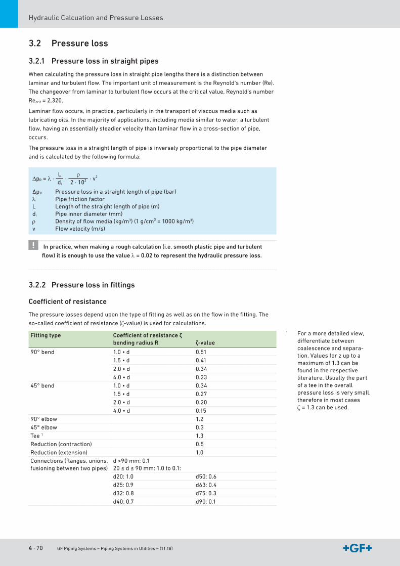
4 · 70 GF Piping Systems – Piping Systems in Utilities – (11.18)
HydraulicCalcuationandPressureLosses
3.2 Pressure loss
3.2.1 Pressure loss in straight pipes
Whencalculatingthepressurelossinstraightpipelengthsthereisadistinctionbetween
laminarandturbulentflow.TheimportantunitofmeasurementistheReynold‘snumber(Re).
Thechangeoverfromlaminartoturbulentflowoccursatthecriticalvalue,Reynold’snumber
Recrit=2,320.
Laminarflowoccurs,inpractice,particularlyinthetransportofviscousmediasuchas
lubricatingoils.Inthemajorityofapplications,includingmediasimilartowater,aturbulent
flow,havinganessentiallysteadiervelocitythanlaminarflowinacross-sectionofpipe,
occurs.
The pressure loss in a straight length of pipe is inversely proportional to the pipe diameter
andiscalculatedbythefollowingformula:
Ldi
∆pR = λ ⋅ρ
2 ⋅ 102⋅ ⋅ v2
ΔpR Pressure loss in a straight length of pipe (bar)λ Pipe friction factorL Length of the straight length of pipe (m)di Pipe inner diameter (mm)ρ Densityofflowmedia(kg/m3)(1g/cm³=1000kg/m3)v Flowvelocity(m/s)
In practice, when making a rough calculation (i.e. smooth plastic pipe and turbulent
flow) it is enough to use the value λ = 0.02 to represent the hydraulic pressure loss.
3.2.2 Pressure loss in fittings
Coefficient of resistance
Thepressurelossesdependuponthetypeoffittingaswellasontheflowinthefitting.The
so-calledcoefficientofresistance(ζ-value)isusedforcalculations.
Fitting type Coefficient of resistance ζbending radius R ζ-value
90°bend 1.0•d 0.511.5•d 0.41
2.0•d 0.344.0•d 0.23
45° bend 1.0•d 0.341.5•d 0.272.0•d 0.204.0•d 0.15
90°elbow 1.245°elbow 0.3Tee 1 1.3Reduction (contraction) 0.5Reduction (extension) 1.0Connections(flanges,unions,fusioningbetweentwopipes)
d>90mm:0.120≤d≤90mm:1.0to0.1:d20:1.0 d50:0.6d25:0.9 d63:0.4d32:0.8 d75:0.3d40:0.7 d90:0.1
1 Foramoredetailedview,differentiatebetweencoalescence and separa-tion.Valuesforzuptoamaximumof1.3canbefound in the respective literature. Usually the part of a tee in the overall pressure loss is very small, therefore in most cases ζ = 1.3canbeused.
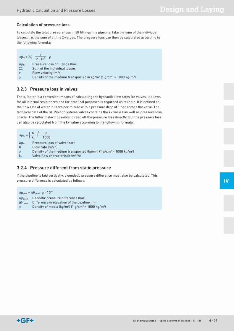
GF Piping Systems – Piping Systems in Utilities – (11.18) 4 · 71
Design and LayingHydraulicCalcuationandPressureLosses
IV
Calculation of pressure loss
Tocalculatethetotalpressurelossinallfittingsinapipeline,takethesumoftheindividual
losses, i. e. the sum of all the ζ-values.Thepressurelosscanthenbecalculatedaccordingtothefollowingformula:
∆pFi = Σζ ⋅v2
2 ⋅ 105 ⋅ ρ
ΔpFi Pressurelossoffittings(bar)Σζ Sum of the individual lossesv Flowvelocity(m/s)ρ Densityofthemediumtransportedinkg/m3(1g/cm3=1000kg/m3)
3.2.3 Pressure loss in valves
Thekv factorisaconvenientmeansofcalculatingthehydraulicflowratesforvalves.Itallows
forallinternalresistancesandforpracticalpurposesisregardedasreliable.Itisdefinedas
theflowrateofwaterinlitersperminutewithapressuredropof1baracrossthevalve.The
technicaldataoftheGFPipingSystemsvalvescontainsthekvvaluesaswellaspressureloss
charts.Thelattermakeitpossibletoreadoffthepressurelossdirectly.Butthepressureloss
canalsobecalculatedfromthekvvalueaccordingtothefollowingformula:
∆pAr =ρ
1000⋅Q
kv
2
ΔpAr Pressure loss of valve (bar)Q Flowrate(m3/h)ρ Densityofthemediumtransported(kg/m3)(1g/cm3=1000kg/m3)kv Valveflowcharacteristic(m3/h)
3.2.4 Pressure different from static pressure
Ifthepipelineislaidvertically,ageodeticpressuredifferencemustalsobecalculated.This
pressuredifferenceiscalculatedasfollows:
∆pgeod = ∆Hgeod ⋅ ρ ⋅ 10–4
Δpgeod Geodeticpressuredifference(bar)ΔHgeod Differenceinelevationofthepipeline(m)ρ Densityofmedia(kg/m3)(1g/cm3=1000kg/m3)
4 · 72 GF Piping Systems – Piping Systems in Utilities – (11.18)
HydraulicCalcuationandPressureLosses
3.2.5 Sum of pressure losses
Thesumofallthepressurelossesinthepipelineisgivenby:
Σ∆p = ∆pR + ∆pFi + ∆pAr + ∆pgeo
Example of a pressure loss calculation
Thefollowingexampleshowsthecalculationtodeterminethepressurelossofa
pipeline:
PEpipe
SDR11flowrate
Medium
Density of medium
Length of straight pipe sections
Elevationdifference
d110 mm
10l/s
Wasser
1g/cm3
15 m
2.0 m
Number of fittings
12xelbow90°
4xelbow45°
3xtees
3xunions
2xflangeconnections
1xdiaphragmvalveTyp039,
100%opened
ThewallthicknessofthispipelinecanbecalculatedasfollowswiththeSDR:
e = = = 10 mmd
SDR110 mm
11
Theinnerdiameterofthepipelineisasfollows:
di = d – 2 ⋅ e = d – = 90 mm2 ⋅ dSDR
Withtherequiredflowrateof10l/s,theflowvelocityisasfollows:
v = 1275 ⋅ = 1275 ⋅ = 1.57 Q2
di2
msec
msec
10902
Pressure loss Formula
Pressure loss of strait pipes∆pR = 0.02 ⋅ ⋅ 1.572 = 0.04 bar
1590
10002 102
Pressurelossoffittingsandjoints
Σζ = (12 ⋅ 1.2) + (4 ⋅ 0.3) + (3 ⋅ 1.3) + (5 ⋅ 0.1) = 20
∆pFi = 20 ⋅ 1000 = 0.25 bar1.572
2 105
Pressurelossofvalve,100%opened.Withtheflowcharac-teristics diagram of diaphragm valve,type039,kv-value 702.6l/min(flowrate10l/s=36m3/h)
∆pAr = = 0.0026 bar10001000
36702.6
2
⋅
Pressure loss oh height difference
∆pgeod = 2.0 ⋅ 1000 ⋅ 10–4 = 0.2 bar
Total pressure loss of the pipeline
Σ∆p = 0.04 bar + 0.25 bar + 0.0026 bar + 0.2 bar = 0.4917 bar
T4.11 Formulas for calculation of pressure losses
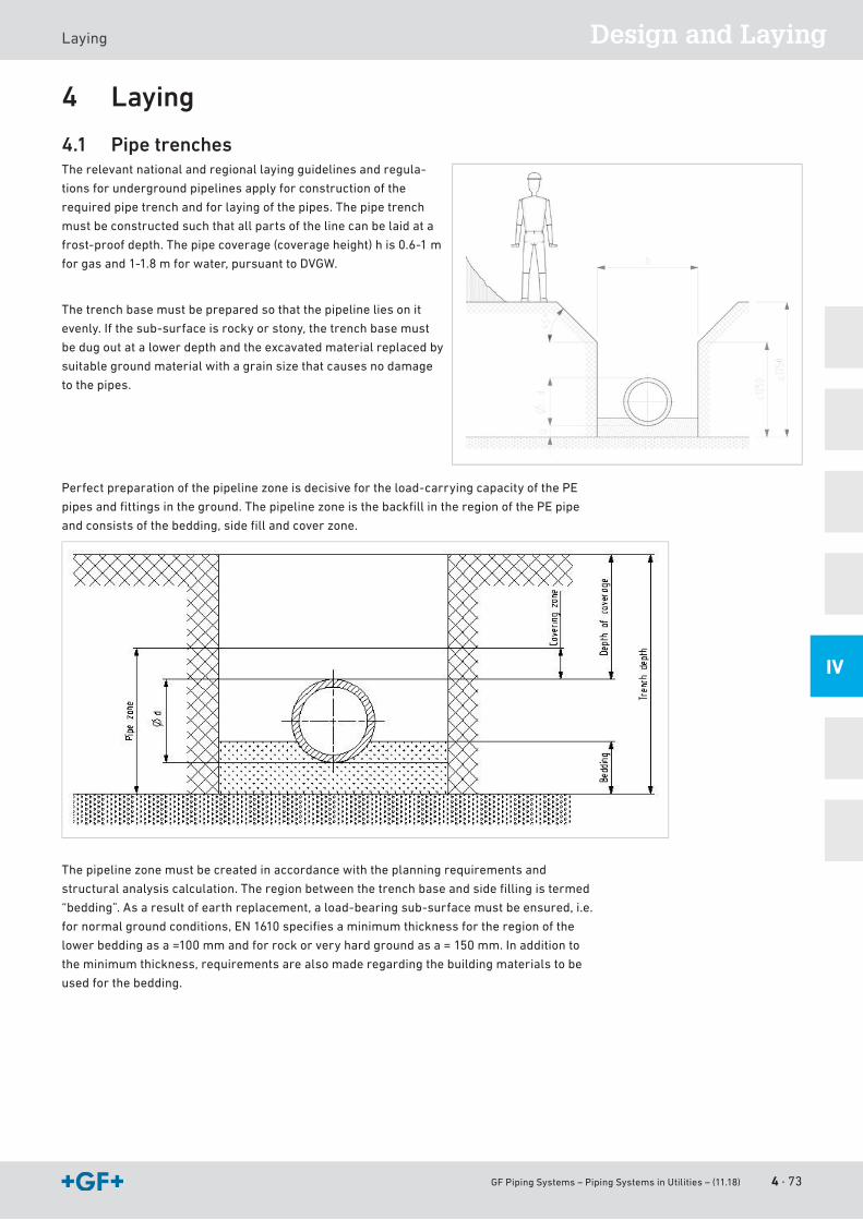
GF Piping Systems – Piping Systems in Utilities – (11.18) 4 · 73
Design and LayingLaying
IV
4 Laying
4.1 Pipe trenchesTherelevantnationalandregionallayingguidelinesandregula-
tions for underground pipelines apply for construction of the
requiredpipetrenchandforlayingofthepipes.Thepipetrench
must be constructed such that all parts of the line can be laid at a
frost-proofdepth.Thepipecoverage(coverageheight)his0.6-1 m
forgasand1-1.8mforwater,pursuanttoDVGW.
The trench base must be prepared so that the pipeline lies on it
evenly.Ifthesub-surfaceisrockyorstony,thetrenchbasemust
bedugoutatalowerdepthandtheexcavatedmaterialreplacedby
suitablegroundmaterialwithagrainsizethatcausesnodamage
to the pipes.
Perfectpreparationofthepipelinezoneisdecisivefortheload-carryingcapacityofthePE
pipesandfittingsintheground.ThepipelinezoneisthebackfillintheregionofthePEpipe
andconsistsofthebedding,sidefillandcoverzone.
Thepipelinezonemustbecreatedinaccordancewiththeplanningrequirementsand
structuralanalysiscalculation.Theregionbetweenthetrenchbaseandsidefillingistermed
“bedding”.Asaresultofearthreplacement,aload-bearingsub-surfacemustbeensured,i.e.
fornormalgroundconditions,EN1610specifiesaminimumthicknessfortheregionofthe
lowerbeddingasa=100mmandforrockorveryhardgroundasa=150mm.Inadditionto
theminimumthickness,requirementsarealsomaderegardingthebuildingmaterialstobe
used for the bedding.
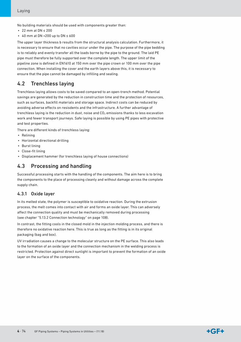
4 · 74 GF Piping Systems – Piping Systems in Utilities – (11.18)
Laying
Nobuildingmaterialsshouldbeusedwithcomponentsgreaterthan:
• 22mmatDN≤200
• 40mmatDN>200uptoDN≤600
Theupperlayerthicknessbresultsfromthestructuralanalysiscalculation.Furthermore,it
is necessary to ensure that no cavities occur under the pipe. The purpose of the pipe bedding
istoreliablyandevenlytransferalltheloadsbornebythepipetotheground.ThelaidPE
pipe must therefore be fully supported over the complete length. The upper limit of the
pipelinezoneisdefinedinEN1610at150mmoverthepipecrownor100mmoverthepipe
connection. When installing the cover and the earth layers above this, it is necessary to
ensurethatthepipecannotbedamagedbyinfillingandsealing.
4.2 Trenchless layingTrenchlesslayingallowscoststobesavedcomparedtoanopen-trenchmethod.Potential
savings are generated by the reduction in construction time and the protection of resources,
suchassurfaces,backfillmaterialsandstoragespace.Indirectcostscanbereducedby
avoidingadverseeffectsonresisdentsandtheinfrastructure.Afurtheradvantageof
trenchlesslayingisthereductionindust,noiseandCO2emissionsthankstolessexcavation
workandfewertransportjourneys.SafelayingispossiblebyusingPEpipeswithprotective
and test properties.
Therearedifferentkindsoftrenchlesslaying:
• Relining
• Horizontaldirectionaldrilling
• Burst lining
• Close-fitlining
• Displacement hammer (for trenchless laying of house connections)
4.3 Processing and handlingSuccessfulprocessingstartswiththehandlingofthecomponents.Theaimhereistobring
thecomponentstotheplaceofprocessingcleanlyandwithoutdamageacrossthecomplete
supply chain.
4.3.1 Oxide layer
Initsmeltedstate,thepolymerissusceptibletooxidativereaction.Duringtheextrusion
process,themeltcomesintocontactwithairandformsanoxidelayer.Thiscanadversely
affecttheconnectionqualityandmustbemechanicallyremovedduringprocessing
(seechapter“5.13.2Connectiontechnology”onpage108).
Incontrast,thefittingcoolsintheclosedmoldintheinjectionmoldingprocess,andthereis
thereforenooxidativereactionhere.Thisistrueaslongasthefittingisinitsoriginal
packaging(bagandbox).
UVirradiationcausesachangetothemolecularstructureonthePEsurface.Thisalsoleads
totheformationofanoxidelayerandtheconnectionmechanismintheweldingprocessis
restricted. Protection against direct sunlight is important to prevent the formation of an oxide
layer on the surface of the components.
GF Piping Systems – Piping Systems in Utilities – (11.18) 4 · 75
Design and LayingLaying
IV
4.3.2 Packaging concept
Forsafeandreliabletransport,theELGEFPlusproductsarepackedindividuallyorin
packagingunitsinaplasticbagandabox.
Theboxescanbestackedandprotectthefittingagainstsunlight,dirtanddamage.AllELGEF
Pluselectrofusioncomponentsarealsoindividuallypackedinbags.Aircirculationinthe
packagingisreducedtoaminimum.Thispreventsareactiveenvironmentfromoccurring.
Thepackagingprotectsagainstdirt.
Injection-moldedELGEFPlusproductsarepackedinbagsandboxesdirectlyafterproduc-
tion.PEballvalvesandspigotfittingsinlargerdimensions(>d315und>d280T90°reduced)
arepackedinboxes.
SeamlesselbowsaremadeofPEpipeandpackedonpalletswithoutaboxandplasticbag.
4.3.3 Storage
Pipes
Thepipestoragesurfacemustbelevelandfreeofstones.Pipesmustbelayeredandstacked
inawaythatavoidstheriskofdamageorpermanentdeformation.Larger-diameter,thin-wal-
ledpipesmustbefittedwithstiffeningrings.Avoidsingle-pointornarrowlongitudinal
supports.
Thefollowingtablegivesrecommendedmaximumstackingheightsfornon-palletpipe
storage.Providedpipesarestackedonpalletsandprotectedagainstsidewaysmovement,
thenominalstackingheightsspecifiedinthetablemaybeincreasedby50%.
Pipestorageareasshouldbeaswell-protectedaspossible.Absorptionofoil,solventsand
other chemicals must be avoided at all costs during storage.
Stored pipes must not be exposed to the elements more than absolutely necessary, i.e. they
shouldbekeptinacoveredwarehouse.Ifstoredoutdoors(e.g.onaconstructionsite),they
shouldbecoveredwithsheetingforprotectionagainsttheweather(e.g.UVradiation).
One-sidedwarmingfromexposuretothesuncouldcausedeformations.
Pipesandpartsshouldbeusedintheorderofmanufacture/delivery,toensureproper
warehouseturnoveroftheplasticmaterial.
Material Permissible stacking height(m)
PE100/PE100RC 1.0
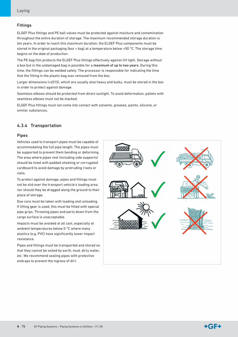
4 · 76 GF Piping Systems – Piping Systems in Utilities – (11.18)
Laying
Fittings
ELGEFPlusfittingsandPEballvalvesmustbeprotectedagainstmoistureandcontamination
throughout the entire duration of storage. The maximum recommended storage duration is
tenyears.Inordertoreachthismaximumduration,theELGEFPluscomponentsmustbe
storedintheoriginalpackaging(box+bag)atatemperaturebelow+50°C.Thestoragetime
begins on the date of production.
ThePEbagfilmprotectstheELGEFPlusfittingseffectivelyagainstUVlight.Storagewithout
a box but in the undamaged bag is possible for a maximum of up to two years. During this
time,thefittingscanbeweldedsafely.Theprocessorisresponsibleforindicatingthetime
thatthefittingintheplasticbagwasremovedfromthebox.
Largerdimensions(>d315),whichareusuallyalsoheavyandbulky,mustbestoredinthebox
in order to protect against damage.
Seamlesselbowsshouldbeprotectedfromdirectsunlight.Toavoiddeformation,palletswith
seamlesselbowsmustnotbestacked.
ELGEFPlusfittingsmustnotcomeintocontactwithsolvents,greases,paints,silicone,or
similar substances.
4.3.4 Transportation
PipesVehiclesusedtotransportpipesmustbecapableof
accommodating the full pipe length. The pipes must
be supported to prevent them bending or deforming.
Theareawherepipesrest(includingsidesupports)
shouldbelinedwithpaddedsheetingorcorrugated
cardboard to avoid damage by protruding rivets or
nails.
Toprotectagainstdamage,pipesandfittingsmust
notbeslidoverthetransportvehicle’sloadingarea,
nor should they be dragged along the ground to their
place of storage.
Duecaremustbetakenwithloadingandunloading.
Ifliftinggearisused,thismustbefittedwithspecial
pipegrips.Throwingpipesandpartsdownfromthe
cargo surface is unacceptable.
Impactsmustbeavoidedatallcost,especiallyat
ambienttemperaturesbelow0°Cwheremany
plastics(e.g.PVC)havesignificantlylowerimpact
resistance.
Pipesandfittingsmustbetransportedandstoredso
thattheycannotbesoiledbyearth,mud,dirtywater,
etc.Werecommendsealingpipeswithprotective
endcaps to prevent the ingress of dirt.
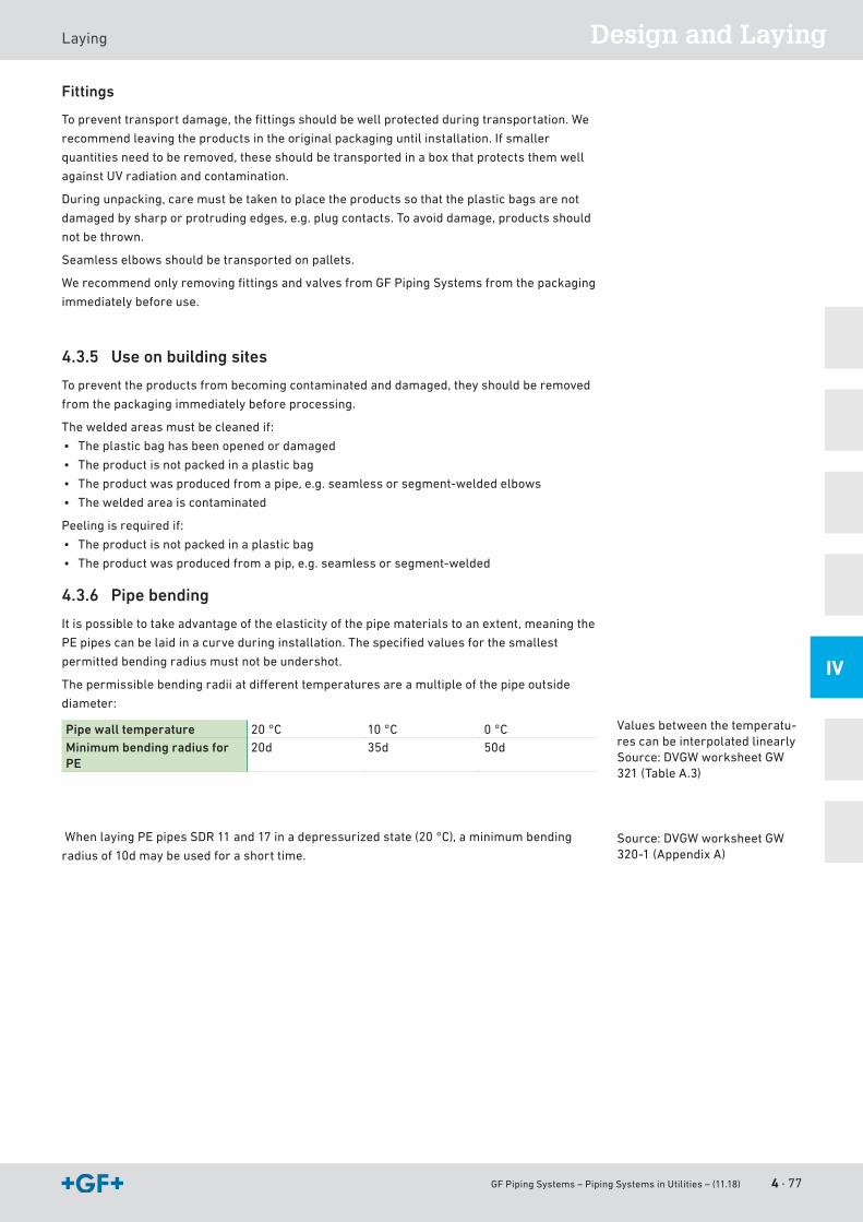
GF Piping Systems – Piping Systems in Utilities – (11.18) 4 · 77
Design and LayingLaying
IV
Fittings
Topreventtransportdamage,thefittingsshouldbewellprotectedduringtransportation.We
recommendleavingtheproductsintheoriginalpackaginguntilinstallation.Ifsmaller
quantitiesneedtoberemoved,theseshouldbetransportedinaboxthatprotectsthemwell
againstUVradiationandcontamination.
Duringunpacking,caremustbetakentoplacetheproductssothattheplasticbagsarenot
damaged by sharp or protruding edges, e.g. plug contacts. To avoid damage, products should
notbethrown.
Seamlesselbowsshouldbetransportedonpallets.
WerecommendonlyremovingfittingsandvalvesfromGFPipingSystemsfromthepackaging
immediately before use.
4.3.5 Use on building sites
To prevent the products from becoming contaminated and damaged, they should be removed
fromthepackagingimmediatelybeforeprocessing.
Theweldedareasmustbecleanedif:
• The plastic bag has been opened or damaged
• Theproductisnotpackedinaplasticbag
• Theproductwasproducedfromapipe,e.g.seamlessorsegment-weldedelbows
• Theweldedareaiscontaminated
Peelingisrequiredif:
• Theproductisnotpackedinaplasticbag
• Theproductwasproducedfromapip,e.g.seamlessorsegment-welded
4.3.6 Pipe bending
Itispossibletotakeadvantageoftheelasticityofthepipematerialstoanextent,meaningthe
PEpipescanbelaidinacurveduringinstallation.Thespecifiedvaluesforthesmallest
permitted bending radius must not be undershot.
Thepermissiblebendingradiiatdifferenttemperaturesareamultipleofthepipeoutside
diameter:
Pipe wall temperature 20 °C 10 °C 0 °CMinimum bending radius for PE
20d 35d 50d
WhenlayingPEpipesSDR11and17inadepressurizedstate(20°C),aminimumbending
radius of 10d may be used for a short time.
Valuesbetweenthetemperatu-res can be interpolated linearlySource:DVGWworksheetGW321(TableA.3)
Source:DVGWworksheetGW320-1(AppendixA)

4 · 78 GF Piping Systems – Piping Systems in Utilities – (11.18)
Laying
4.4 Internal pressure and leak test
4.4.1 Introduction to pressure testing
Overview of the different testing methods
Testing method
Internal pressure test Leak test
Medium Water Gas* Compressed air1)
Gas/air(oil-free)
Gas/air(oil-free)
Type Incompres-sible
Compressible Compressible Compressible Compressible
Test pressure (overpres-sure)
Pp (perm)
or0.85 • Pp (perm)
Operatingpressure+ 2 bar
Operatingpressure+ 2 bar
0.5 bar 1.5 bar
Hazardpotentialduring pressure test
Low High High Low Medium
Material All plastics PE PE All plastics ABSInformativevalve
High:Proof of resistance to pressure including tightness against test medium
High:Proof of resistance to pressure including tightness against test medium
High:Proof of resistance to pressure including tightness against test medium
Low Mittel Medium
Varioustestmethodsforpressureandtightnesstestsareuseddependingonnationaland
internationalstandardsandguidelinesaswellaslocalconditions.Theseincludeforexample
contractionmethods,pressurelossmethods,pressuredifferencemethodsorvisual
methods. They vary in the test process, test time and test pressure.
Thepurposeofapressuretestis:
• Ensuretheresistancetopressureofthepipeline,and
• Showtheleak-tightnessagainstthetestmedium
Usually,theinternalpressuretestisdoneasawaterpressuretestandonlyinexceptional
cases(underconsiderationofspecialsafetyprecautions)asagaspressuretestwithairor
nitrogen.
Thefollowingcomparisonattemptstopointoutthedifferencebetweenwaterandairasatest
medium:
Waterisanincompressiblemedium,i.e.settinga1mPEpipewithadiameterofd160undera
pressureof3barresultsinanenergyofapprox.1joule.Incontrast,airisacompressible
medium.Thesamepipewithtestpressureof3baralreadystoresanenergyof5,000joule.If
therewereafailureduringtheinternalpressuretest,thewater-filledpipewouldjumpup
0.02m,theair-filledpipe100m.
1) Observetheapplicablesafety precautions. More information is available in DVS2210-1addendum2.
GF Piping Systems – Piping Systems in Utilities – (11.18) 4 · 79
Design and LayingLaying
IV
Fracture behavior of plastics
Incaseofafailure,thermoplasticmaterialsshowdifferentbehaviors.Hence,PEandPB
exhibitaductilebehavior(andABSslightlylower),sothatbrittlefracturecannotoccur.
Nevertheless,thefollowingsafetyprecautionsmustbetakenintoconsiderationduringthe
internalpressuretest.Asmentionedbefore,thepressuretestisthefirstloadingplacedon
thepipelineandisintendedtouncoveranyexistingprocessingfaults(e.g.insufficient
fusioning).
Gasleak-tightnesscannotbedemonstratedbyawaterpressuretest,notevenwithincreased
testpressure!
4.4.2 Internal pressure test with water or a similar incompressible test medium overview
Overview
Theinternalpressuretestisdonewheninstallationworkhasbeencompletedandpresuppo-
ses an operational pipeline or operational test sections. The test pressure load is intended to
furnish experimental proof of operational safety. The test pressure is not based on the
operatingpressure,butratherontheinternalpressureloadcapacity,basedonthepipewall
thickness.
Addendum2ofDVS2210-1formsthebasisforthefollowinginformation.Thisreplacesthe
datainDVS2210-1entirely.Themodificationsbecamenecessarybecausethereference
value„nominalpressure(PN)“isbeingusedlessandlesstodeterminethetestpressure
(1.5 •PN,bzw.1.3•PN)andisbeingreplacedbySDR.Inaddition,ashort-termoverloador
evenareductionintheservicelifecanoccurifthepipewalltemperatureTR = 20 °C is
exceeded by more than 5 °C in the course of the internal pressure test based on the nominal
pressure.
Testpressuresare,therefore,determinedinrelationtoSDRandthepipewalltemperature.
The100-hvaluefromthelong-termbehaviordiagramisusedforthetestpressure.
Test parameters
Thefollowingtableprovidesrecommendedmethodsforperformingtheinternalpressuretest.
Object Pre-test Main test
Test duration (depends on the length of the pipeline sections)
≤Pp (perm) ≤0.85Pp (perm)
Prüfdauer (abhängig von der Länge der Rohrleitungsabschnitte)
L≤100m:3h100m<L≤500m:6h
L≤100m:3h100m<L≤500m:6h
Checksduringthetest(testpressureandtemperature progression must be recorded)
Atleast3checks,distributed over the testdurationwithrestoring the test pressure
Atleast2checks,distributed over the testdurationwithoutrestoring the test pressure
Pre-test
Thepre-testservestopreparethepipingsystemfortheactualtest(maintest).Inthecourse
ofpre-testing,atension-expansionequilibriuminrelationtoanincreaseinvolumewill
developinthepipingsystem.Amaterial-relateddropinpressurewilloccurwhichwill
requirerepeatedpumpingtorestorethetestpressureandalsofrequentlyare-tighteningof
theflangeconnectionbolts.
Theguidelinesforanexpansion-relatedpressuredecreaseinpipesare:
Material Pressure drop(bar/h)
PE 1.2
4 · 80 GF Piping Systems – Piping Systems in Utilities – (11.18)
Laying
Main test
Inthecontextofthemaintest,amuchsmallerdropinpressurecanbeexpectedatconstant
pipewalltemperaturessothatitisnotnecessarytopumpagain.Thecheckscanfocus
primarilyonleakdetectionattheflangejointsandanypositionchangesofthepipe.
Observe if using compensators
Ifthepipelinetobetestedcontainscompensators,ithasaninfluenceontheexpectedaxial
forcesonthefixedpointsofthepipeline.Becausethetestpressureishigherthanthe
operatingpressure,theaxialforcesonthefixedpointsincreaseproportionately.Thishasto
betakenintoaccountwhendesigningthefixedpoints.
Observe if using valves
Whenusingavalveattheendofapipeline(endorfinalvalve),thevalveandthepipeend
shouldbeclosedbyadummyflangeorcap.Thispreventsaninadvertentopeningofthevalve
and exit of the medium or any pollution of the inside of the valve.
Filling the pipeline
Beforestartingwiththeinternalpressuretest,thefollowingpointsmustbechecked:
• Was installation done according to the available plans?
• Allpressurereliefdevicesandflaptrapsmountedintheflowdirection?
• All end valves shut?
• Valvesinfrontofotherdevicesareshuttoprotectagainstpressure?
• Visualinspectionofalljoints,pumps,measurementdevicesandtanks?
• Hasthewaitingperiodafterthelastfusion/cementingbeenobserved?
Nowthepipelinecanbefilledfromthegeodeticlowestpoint.Specialattentionshouldbe
giventotheairvent.Ifpossible,ventsshouldbeprovidedatallthehighpointsofthepipeline
andtheseshouldbeopenwhenfillingthesystem.Flushingvelocityshouldbeatleast1m/s.
Adequatetimeshouldbeallowedbetweenfillingandtestingthepipeline,sothattheair
containedinthepipingsystemcanescapeviathevents:approx.6-12h,dependingonthe
nominal diameter.
Determining the test pressure
Thepermissibletestpressureiscalculatedaccordingtothefollowingformula:
Pp(zul) = ⋅20 ⋅ σv(T, 100 h)
Sp ⋅ AG 1
SDR
σv(T, 100 h) Long-termcreepstrengthforpipewalltemperatureTR (at t = 100 h)Sp Minimumsafetyfactorforlong-termcreepstrengthAG Processingorgeometry-specificfactorthatreducestheallowabletestpressureTR Pipewalltemperature:averagevalueoftestmediumtemperatureandpipe
surface temperature
Material Sp Minimum safety factor
PE80,PE100 1.25
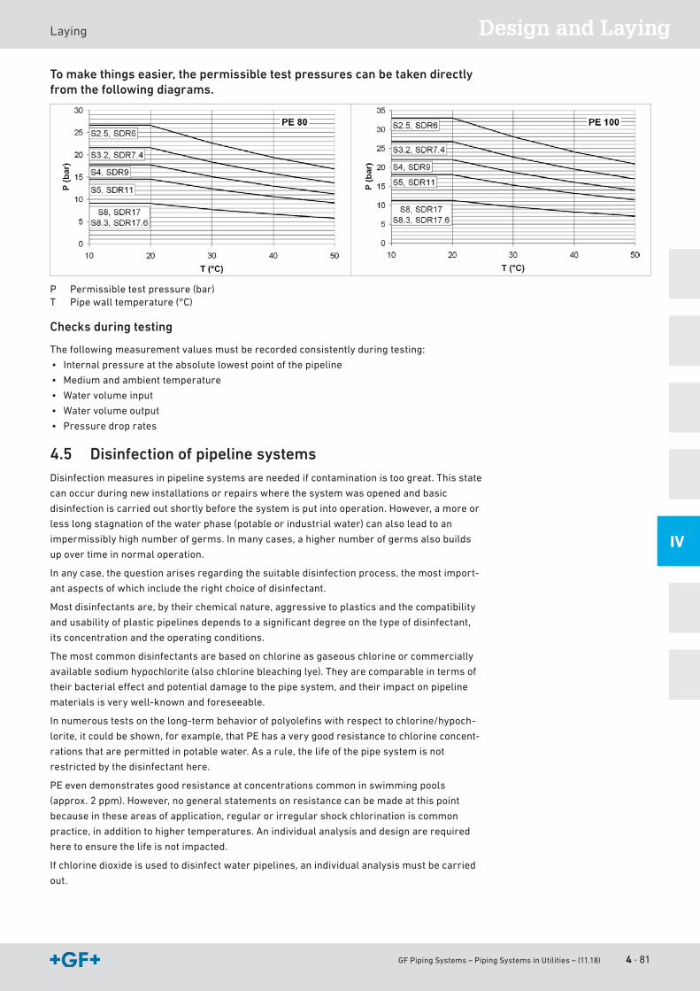
GF Piping Systems – Piping Systems in Utilities – (11.18) 4 · 81
Design and LayingLaying
IV
To make things easier, the permissible test pressures can be taken directly from the following diagrams.
P Permissible test pressure (bar)T Pipewalltemperature(°C)
Checks during testing
Thefollowingmeasurementvaluesmustberecordedconsistentlyduringtesting:
• Internalpressureattheabsolutelowestpointofthepipeline
• Medium and ambient temperature
• Water volume input
• Water volume output
• Pressure drop rates
4.5 Disinfection of pipeline systemsDisinfection measures in pipeline systems are needed if contamination is too great. This state
canoccurduringnewinstallationsorrepairswherethesystemwasopenedandbasic
disinfectioniscarriedoutshortlybeforethesystemisputintooperation.However,amoreor
lesslongstagnationofthewaterphase(potableorindustrialwater)canalsoleadtoan
impermissiblyhighnumberofgerms.Inmanycases,ahighernumberofgermsalsobuilds
up over time in normal operation.
Inanycase,thequestionarisesregardingthesuitabledisinfectionprocess,themostimport-
antaspectsofwhichincludetherightchoiceofdisinfectant.
Most disinfectants are, by their chemical nature, aggressive to plastics and the compatibility
andusabilityofplasticpipelinesdependstoasignificantdegreeonthetypeofdisinfectant,
its concentration and the operating conditions.
The most common disinfectants are based on chlorine as gaseous chlorine or commercially
available sodium hypochlorite (also chlorine bleaching lye). They are comparable in terms of
theirbacterialeffectandpotentialdamagetothepipesystem,andtheirimpactonpipeline
materialsisverywell-knownandforeseeable.
Innumeroustestsonthelong-termbehaviorofpolyolefinswithrespecttochlorine/hypoch-
lorite,itcouldbeshown,forexample,thatPEhasaverygoodresistancetochlorineconcent-
rationsthatarepermittedinpotablewater.Asarule,thelifeofthepipesystemisnot
restricted by the disinfectant here.
PEevendemonstratesgoodresistanceatconcentrationscommoninswimmingpools
(approx.2ppm).However,nogeneralstatementsonresistancecanbemadeatthispoint
becauseintheseareasofapplication,regularorirregularshockchlorinationiscommon
practice,inadditiontohighertemperatures.Anindividualanalysisanddesignarerequired
here to ensure the life is not impacted.
Ifchlorinedioxideisusedtodisinfectwaterpipelines,anindividualanalysismustbecarried
out.
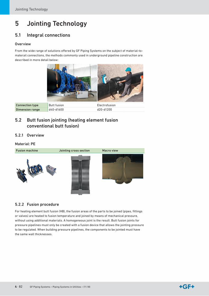
4 · 82 GF Piping Systems – Piping Systems in Utilities – (11.18)
JointingTechnology
5 Jointing Technology
5.1 Integral connections
Overview
FromthewiderangeofsolutionsofferedbyGFPipingSystemsonthesubjectofmaterial-to-
materail connections, the methods commonly used in underground pipeline construction are
describedinmoredetailbelow:
Connection type Butt fusion ElectrofusionDimension range d40-d1600 d20-d1200
5.2 Butt fusion jointing (heating element fusion conventional butt fusion)
5.2.1 Overview
Material: PE
Fusion machine Jointing cross section Macro view
5.2.2 Fusion procedure
Forheatingelementbuttfusion(HB),thefusionareasofthepartstobejoined(pipes,fittings
or valves) are heated to fusion temperature and joined by means of mechanical pressure,
withoutusingadditionalmaterials.Ahomogeneousjointistheresult.Buttfusionjointsfor
pressurepipelinesmustonlybecreatedwithafusiondevicethatallowsthejointingpressure
to be regulated. When building pressure pipelines, the components to be jointed must have
thesamewallthicknesses.
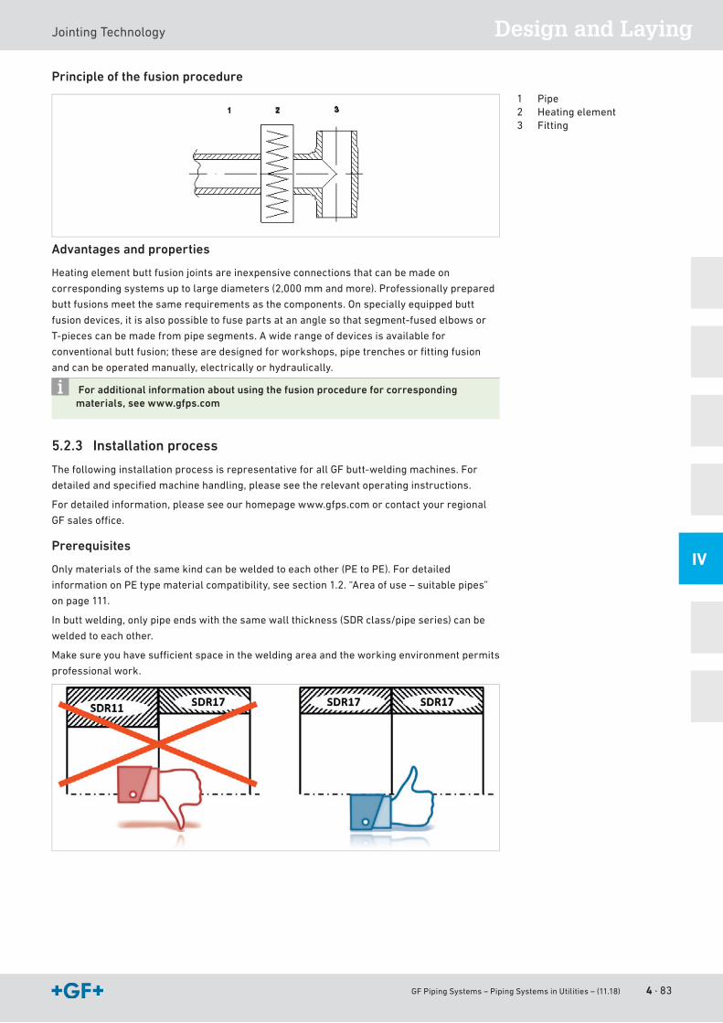
GF Piping Systems – Piping Systems in Utilities – (11.18) 4 · 83
Design and LayingJointingTechnology
IV
Principle of the fusion procedure
Advantages and properties
Heatingelementbuttfusionjointsareinexpensiveconnectionsthatcanbemadeon
corresponding systems up to large diameters (2,000 mm and more). Professionally prepared
buttfusionsmeetthesamerequirementsasthecomponents.Onspeciallyequippedbutt
fusiondevices,itisalsopossibletofusepartsatananglesothatsegment-fusedelbowsor
T-piecescanbemadefrompipesegments.Awiderangeofdevicesisavailablefor
conventionalbuttfusion;thesearedesignedforworkshops,pipetrenchesorfittingfusion
and can be operated manually, electrically or hydraulically.
For additional information about using the fusion procedure for corresponding materials, see www.gfps.com
5.2.3 Installation process
ThefollowinginstallationprocessisrepresentativeforallGFbutt-weldingmachines.For
detailedandspecifiedmachinehandling,pleaseseetherelevantoperatinginstructions.
Fordetailedinformation,pleaseseeourhomepagewww.gfps.comorcontactyourregional
GFsalesoffice.
Prerequisites
Onlymaterialsofthesamekindcanbeweldedtoeachother(PEtoPE).Fordetailed
informationonPEtypematerialcompatibility,seesection1.2.“Areaofuse–suitablepipes”
on page 111.
Inbuttwelding,onlypipeendswiththesamewallthickness(SDRclass/pipeseries)canbe
weldedtoeachother.
Makesureyouhavesufficientspaceintheweldingareaandtheworkingenvironmentpermits
professionalwork.
1 Pipe2 Heatingelement3 Fitting

4 · 84 GF Piping Systems – Piping Systems in Utilities – (11.18)
JointingTechnology
a Clean heating element
Beforeeveryweldingoperation,cleanheatingelementwith
dry,clean,lint-freepaper.
• Beforeheating,cleanwithpapertowelsandPEcleaner.
• Inwarmstate,cleanwithdrypapertowels.
Caution–riskofburning
s Align and clamp pipes
To minimize the displacement caused by pipe ovality, the pipes
mustbealignedinaccordancewiththeirsignatures.
Clamppipes/fittingssecurely.Clampwithtwojawsonthefixed
andmoveablesideoftheweldingmachine.
Positionandsupportpipeendssecurelyonrollerblocks,this
makesiteasiertoensureflushalignmentandsecureclamping.
d Planing
Checkwhetherplaneriscleanandfreeofgreaseonbothsides.
Donotplaneuntilimmediatelybeforewelding.
Planeweldingendsflat;even,uninterruptedmachiningatleast
1-1.5xcircumference.
Makesurechipsareremovedeffectivelyandremovechips
continuously. Stop planing intermittently. Remove chips and
checkresultofplaning.
Check:samewallthicknessofweldingends.
f Off set and gap check
Offsetcheck:Maximumpermittedoffset≤10%ofwallthick-
ness
Δsmax.=0.1xs
However,maximumof5mmforwallthicknessesof>30mm
anddiameters>dn630
Gapcheck(valuesasperDVS2207-1):
dn [mm] Gap A [mm]
≤d355 0.5400-630 1.0630-800 1.3800-1000 1.5>1000 2.0
Thencleantheplanedpipeends(pipe,fitting)with100%
vaporizingPEcleanerandlint-free,cleanpapertowels.
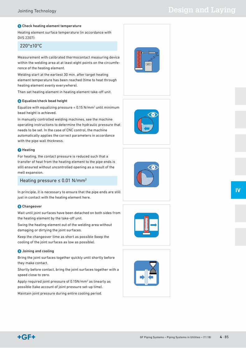
GF Piping Systems – Piping Systems in Utilities – (11.18) 4 · 85
Design and LayingJointingTechnology
IV
g Check heating element temperature
Heatingelementsurfacetemperature(inaccordancewith
DVS 2207):
220°±10°C
Measurementwithcalibratedthermocontactmeasuringdevice
withintheweldingareaatatleasteightpointsonthecircumfe-
rence of the heating element.
Weldingstartattheearliest30min.aftertargetheating
element temperature has been reached (time to heat through
heatingelementevenlyeverywhere).
Thensetheatingelementinheatingelementtake-offunit.
h Equalize/check bead height
Equalizewithequalizingpressure=0.15N/mm2 until minimum
bead height is achieved.
Inmanuallycontrolledweldingmachines,seethemachine
operating instructions to determine the hydraulic pressure that
needstobeset.InthecaseofCNCcontrol,themachine
automatically applies the correct parameters in accordance
withthepipewallthickness.
j Heating
For heating, the contact pressure is reduced such that a
transfer of heat from the heating element to the pipe ends is
stillensuredwithoutuncontrolledopeningasaresultofthe
melt expansion.
Heatingpressure≤0.01N/mm2
Inprinciple,itisnecessarytoensurethatthepipeendsarestill
justincontactwiththeheatingelementhere.
k Changeover
Wait until joint surfaces have been detached on both sides from
theheatingelementbythetake-offunit.
Swingtheheatingelementoutoftheweldingareawithout
damaging or dirtying the joint surfaces.
Keepthechangeovertimeasshortaspossible(keepthe
coolingofthejointsurfacesaslowaspossible).
l Joining and cooling
Bringthejointsurfacestogetherquicklyuntilshortlybefore
theymakecontact.
Shortlybeforecontact,bringthejointsurfacestogetherwitha
speed close to zero.
Applyrequiredjointpressureof0.15N/mm2 as linearly as
possible(takeaccountofjointpressureset-uptime).
Maintain joint pressure during entire cooling period.
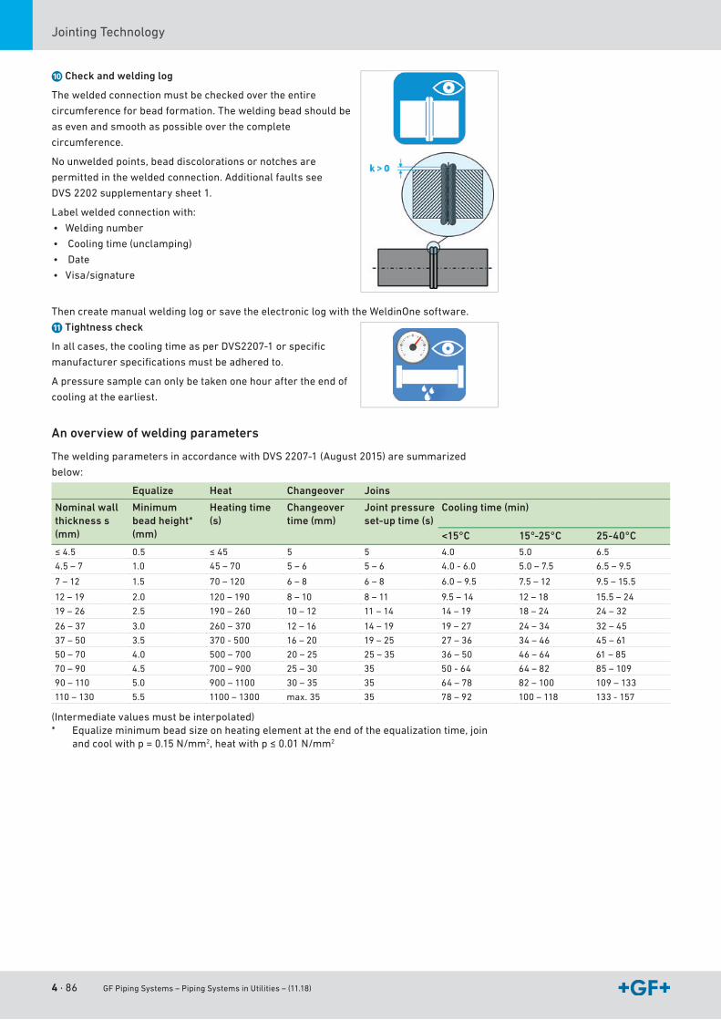
4 · 86 GF Piping Systems – Piping Systems in Utilities – (11.18)
JointingTechnology
; Check and welding log
Theweldedconnectionmustbecheckedovertheentire
circumferenceforbeadformation.Theweldingbeadshouldbe
as even and smooth as possible over the complete
circumference.
Nounweldedpoints,beaddiscolorationsornotchesare
permittedintheweldedconnection.Additionalfaultssee
DVS 2202supplementarysheet1.
Labelweldedconnectionwith:
• Welding number
• Cooling time (unclamping)
• Date
• Visa/signature
ThencreatemanualweldinglogorsavetheelectroniclogwiththeWeldinOnesoftware.
A Tightness check
Inallcases,thecoolingtimeasperDVS2207-1orspecific
manufacturerspecificationsmustbeadheredto.
Apressuresamplecanonlybetakenonehouraftertheendof
cooling at the earliest.
An overview of welding parameters
TheweldingparametersinaccordancewithDVS2207-1(August2015)aresummarized
below:
Equalize Heat Changeover Joins
Nominal wall thickness s (mm)
Minimum bead height* (mm)
Heating time (s)
Changeover time (mm)
Joint pressureset-up time (s)
Cooling time (min)
<15°C 15°-25°C 25-40°C
≤4.5 0.5 ≤45 5 5 4.0 5.0 6.5
4.5 – 7 1.0 45 – 70 5 – 6 5 – 6 4.0-6.0 5.0 – 7.5 6.5–9.5
7 – 12 1.5 70 – 120 6 – 8 6 – 8 6.0–9.5 7.5 – 12 9.5–15.5
12–19 2.0 120–190 8 – 10 8 – 11 9.5–14 12 – 18 15.5 – 24
19–26 2.5 190–260 10 – 12 11 – 14 14–19 18 – 24 24–32
26–37 3.0 260–370 12 – 16 14–19 19–27 24–34 32–45
37–50 3.5 370-500 16 – 20 19–25 27–36 34–46 45 – 61
50 – 70 4.0 500 – 700 20 – 25 25–35 36–50 46 – 64 61 – 85
70–90 4.5 700–900 25–30 35 50-64 64 – 82 85–109
90–110 5.0 900–1100 30–35 35 64 – 78 82 – 100 109–133
110–130 5.5 1100–1300 max.35 35 78–92 100 – 118 133-157
(Intermediatevaluesmustbeinterpolated)* Equalizeminimumbeadsizeonheatingelementattheendoftheequalizationtime,join
andcoolwithp=0.15N/mm2,heatwithp≤0.01N/mm2
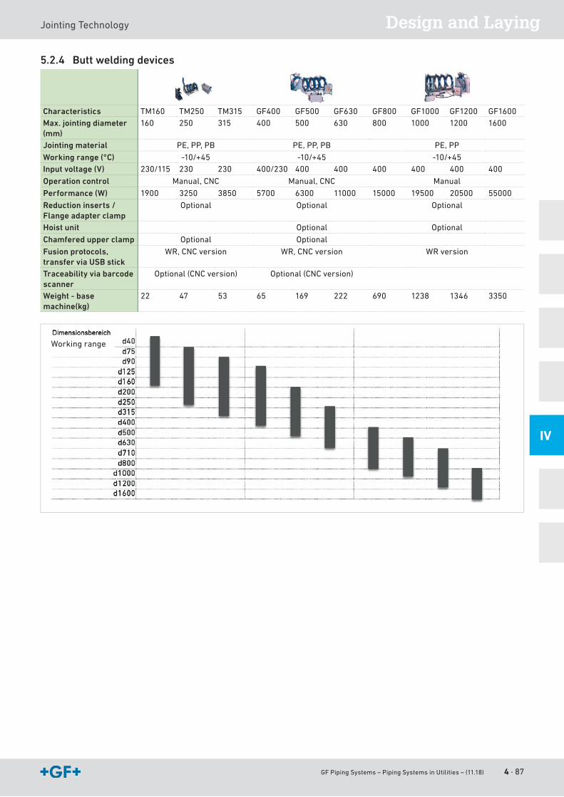
GF Piping Systems – Piping Systems in Utilities – (11.18) 4 · 87
Design and LayingJointingTechnology
IV
5.2.4 Butt welding devices
Characteristics TM160 TM250 TM315 GF400 GF500 GF630 GF800 GF1000 GF1200 GF1600Max. jointing diameter (mm)
160 250 315 400 500 630 800 1000 1200 1600
Jointing material PE,PP,PB PE,PP,PB PE,PP
Working range (°C) -10/+45 -10/+45 -10/+45Input voltage (V) 230/115 230 230 400/230 400 400 400 400 400 400
Operation control Manual,CNC Manual,CNC Manual
Performance (W) 1900 3250 3850 5700 6300 11000 15000 19500 20500 55000
Reduction inserts / Flange adapter clamp
Optional Optional Optional
Hoist unit Optional Optional
Chamfered upper clamp Optional Optional
Fusion protocols, transfer via USB stick
WR,CNCversion WR,CNCversion WR version
Traceability via barcode scanner
Optional(CNCversion) Optional(CNCversion)
Weight - base machine(kg)
22 47 53 65 169 222 690 1238 1346 3350
Workingrange
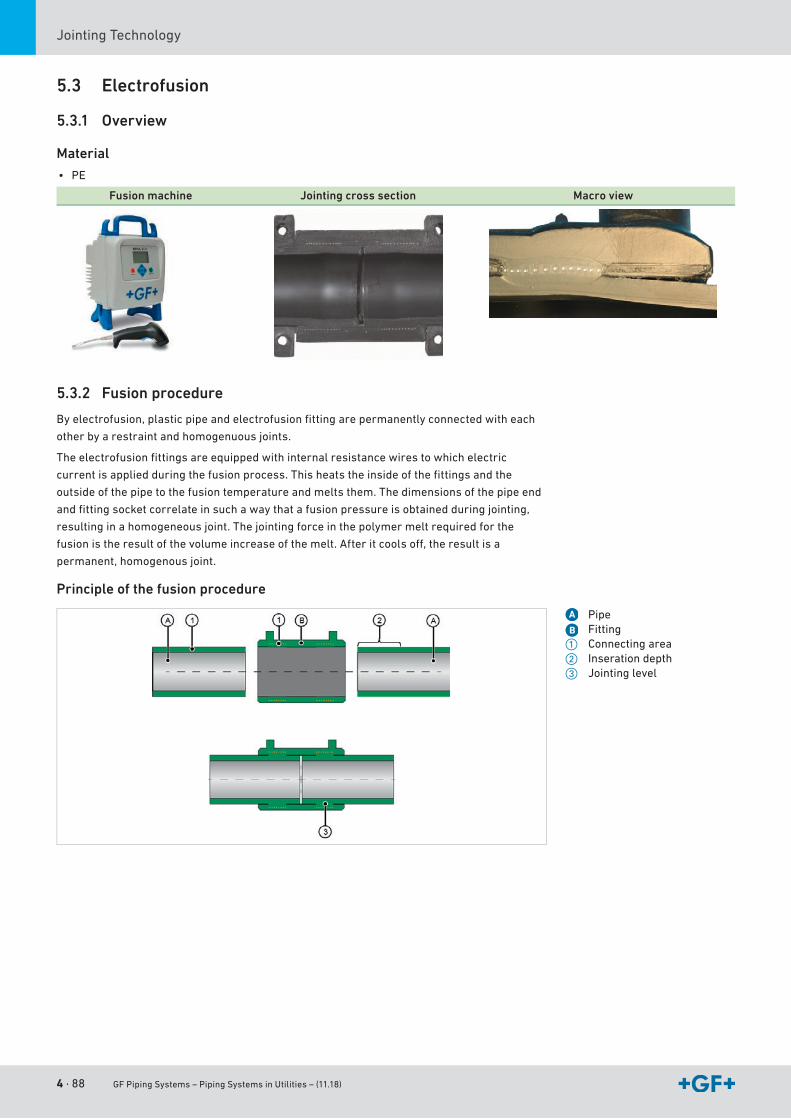
4 · 88 GF Piping Systems – Piping Systems in Utilities – (11.18)
JointingTechnology
5.3 Electrofusion
5.3.1 Overview
Material
• PE
Fusion machine Jointing cross section Macro view
5.3.2 Fusion procedure
Byelectrofusion,plasticpipeandelectrofusionfittingarepermanentlyconnectedwitheach
other by a restraint and homogenuous joints.
Theelectrofusionfittingsareequippedwithinternalresistancewirestowhichelectric
currentisappliedduringthefusionprocess.Thisheatstheinsideofthefittingsandthe
outside of the pipe to the fusion temperature and melts them. The dimensions of the pipe end
andfittingsocketcorrelateinsuchawaythatafusionpressureisobtainedduringjointing,
resultinginahomogeneousjoint.Thejointingforceinthepolymermeltrequiredforthe
fusionistheresultofthevolumeincreaseofthemelt.Afteritcoolsoff,theresultisa
permanent, homogenous joint.
Principle of the fusion procedure
A PipeB Fitting
a Connecting areas Inserationdepthd Jointinglevel
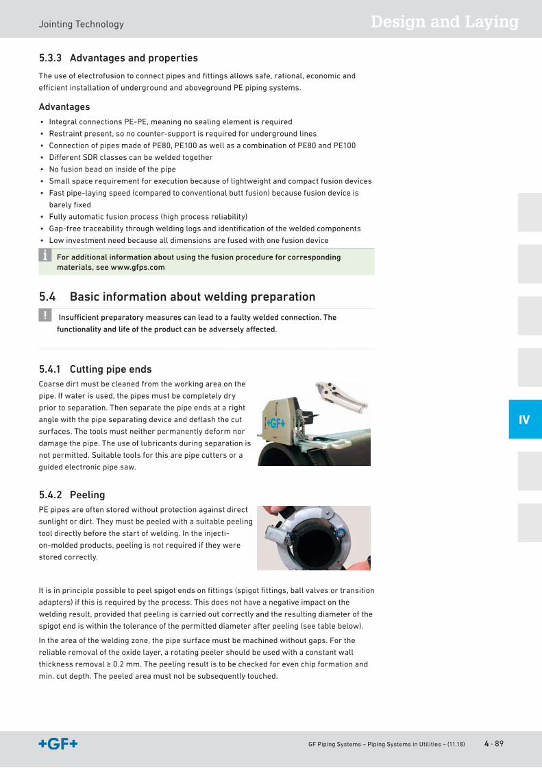
GF Piping Systems – Piping Systems in Utilities – (11.18) 4 · 89
Design and LayingJointingTechnology
IV
5.3.3 Advantages and properties
Theuseofelectrofusiontoconnectpipesandfittingsallowssafe,rational,economicand
efficientinstallationofundergroundandabovegroundPEpipingsystems.
Advantages
• IntegralconnectionsPE-PE,meaningnosealingelementisrequired
• Restraintpresent,sonocounter-supportisrequiredforundergroundlines
• ConnectionofpipesmadeofPE80,PE100aswellasacombinationofPE80andPE100
• DifferentSDRclassescanbeweldedtogether
• Nofusionbeadoninsideofthepipe
• Smallspacerequirementforexecutionbecauseoflightweightandcompactfusiondevices
• Fastpipe-layingspeed(comparedtoconventionalbuttfusion)becausefusiondeviceis
barelyfixed
• Fully automatic fusion process (high process reliability)
• Gap-freetraceabilitythroughweldinglogsandidentificationoftheweldedcomponents
• Lowinvestmentneedbecausealldimensionsarefusedwithonefusiondevice
For additional information about using the fusion procedure for corresponding materials, see www.gfps.com
5.4 Basic information about welding preparation
Insuffi cient preparatory measures can lead to a faulty welded connection. The
functionality and life of the product can be adversely aff ected.
5.4.1 Cutting pipe endsCoarsedirtmustbecleanedfromtheworkingareaonthe
pipe.Ifwaterisused,thepipesmustbecompletelydry
prior to separation. Then separate the pipe ends at a right
anglewiththepipeseparatingdeviceanddeflashthecut
surfaces. The tools must neither permanently deform nor
damage the pipe. The use of lubricants during separation is
not permitted. Suitable tools for this are pipe cutters or a
guidedelectronicpipesaw.
5.4.2 PeelingPEpipesareoftenstoredwithoutprotectionagainstdirect
sunlightordirt.Theymustbepeeledwithasuitablepeeling
tooldirectlybeforethestartofwelding.Intheinjecti-
on-moldedproducts,peelingisnotrequirediftheywere
stored correctly.
Itisinprinciplepossibletopeelspigotendsonfittings(spigotfittings,ballvalvesortransition
adapters)ifthisisrequiredbytheprocess.Thisdoesnothaveanegativeimpactonthe
weldingresult,providedthatpeelingiscarriedoutcorrectlyandtheresultingdiameterofthe
spigotendiswithinthetoleranceofthepermitteddiameterafterpeeling(seetablebelow).
Intheareaoftheweldingzone,thepipesurfacemustbemachinedwithoutgaps.Forthe
reliableremovaloftheoxidelayer,arotatingpeelershouldbeusedwithaconstantwall
thicknessremoval≥0.2mm.Thepeelingresultistobecheckedforevenchipformationand
min.cutdepth.Thepeeledareamustnotbesubsequentlytouched.
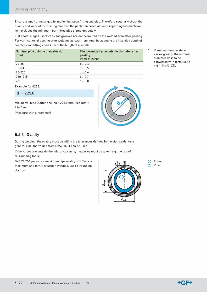
4 · 90 GF Piping Systems – Piping Systems in Utilities – (11.18)
JointingTechnology
Ensureasmallannulargapformationbetweenfittingandpipe.Thereforeregularlycheckthe
qualityandwearofthepeelingbladeonthepeeler.Incasesofdoubtregardingtoomuchwall
removal,seetheminimumpermittedpipediametersbelow.
Flatspots,bulges,scratchesandgroovesarenotpermittedontheweldedareaafterpeeling.
Forverificationofpeelingafterwelding,atleast1cmmustbeaddedtotheinsertiondepthof
couplersandfittingsand4cmtothelengthofasaddle.
Nominal pipe outside diameter dn
(mm)Min. permitted pipe outside diameter after peeling (mm) at 20°C*
20-25 dn-0.432-63 dn-0.575-225 dn-0.6250-315 dn-0.7>315 dn-0.8
Example for d225:
dn = 225.0
Min.perm.pipeØafterpeeling=225.0mm-0.6mm=
224.4 mm
(measurewithcircometer)
5.4.3 Ovality
Duringwelding,theovalitymustbewithinthetolerancesdefinedinthestandards.Asa
generalrule,thevaluesfromDVS2207-1canbeused.
Ifthevaluesareoutsidethetolerancerange,measuresmustbetaken,e.g.theuseof
re-roundingtools.
DVS2207-1permitsamaximumpipeovalityof1.5%ora
maximumof3mm.Forlargerovalities,usere-rounding
clamps.
* Ifambienttemperaturevaries greatly, the nominal diameter dn is to be convertedwithformulaΔd= d * (1+α/3*ΔT).
f Fittingg Pipe
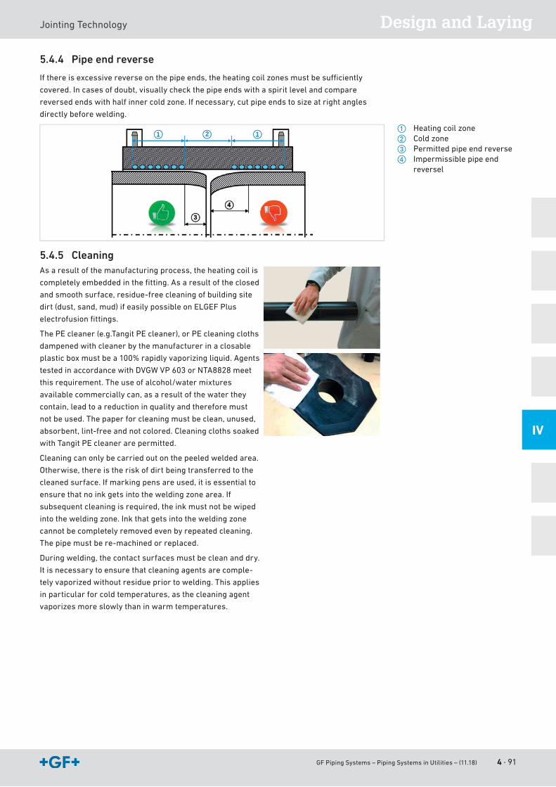
GF Piping Systems – Piping Systems in Utilities – (11.18) 4 · 91
Design and LayingJointingTechnology
IV
5.4.4 Pipe end reverse
Ifthereisexcessivereverseonthepipeends,theheatingcoilzonesmustbesufficiently
covered.Incasesofdoubt,visuallycheckthepipeendswithaspiritlevelandcompare
reversedendswithhalfinnercoldzone.Ifnecessary,cutpipeendstosizeatrightangles
directlybeforewelding.
5.4.5 CleaningAs a result of the manufacturing process, the heating coil is
completelyembeddedinthefitting.Asaresultoftheclosed
andsmoothsurface,residue-freecleaningofbuildingsite
dirt(dust,sand,mud)ifeasilypossibleonELGEFPlus
electrofusionfittings.
ThePEcleaner(e.g.TangitPEcleaner),orPEcleaningcloths
dampenedwithcleanerbythemanufacturerinaclosable
plasticboxmustbea100%rapidlyvaporizingliquid.Agents
testedinaccordancewithDVGWVP603orNTA8828meet
thisrequirement.Theuseofalcohol/watermixtures
availablecommerciallycan,asaresultofthewaterthey
contain,leadtoareductioninqualityandthereforemust
not be used. The paper for cleaning must be clean, unused,
absorbent,lint-freeandnotcolored.Cleaningclothssoaked
withTangitPEcleanerarepermitted.
Cleaningcanonlybecarriedoutonthepeeledweldedarea.
Otherwise,thereistheriskofdirtbeingtransferredtothe
cleanedsurface.Ifmarkingpensareused,itisessentialto
ensurethatnoinkgetsintotheweldingzonearea.If
subsequentcleaningisrequired,theinkmustnotbewiped
intotheweldingzone.Inkthatgetsintotheweldingzone
cannot be completely removed even by repeated cleaning.
Thepipemustbere-machinedorreplaced.
Duringwelding,thecontactsurfacesmustbecleananddry.
Itisnecessarytoensurethatcleaningagentsarecomple-
telyvaporizedwithoutresiduepriortowelding.Thisapplies
in particular for cold temperatures, as the cleaning agent
vaporizesmoreslowlythaninwarmtemperatures.
a Heatingcoilzones Cold zoned Permitted pipe end reversef Impermissiblepipeend
reversel
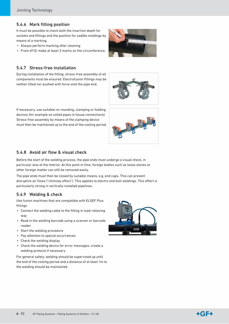
4 · 92 GF Piping Systems – Piping Systems in Utilities – (11.18)
JointingTechnology
5.4.6 Mark fi tting positionItmustbepossibletocheckboththeinsertiondepthfor
socketsandfittingsandthepositionforsaddlemoldingsby
meansofamarking.
• Alwaysperformmarkingaftercleaning
• Fromd110,makeatleast3marksonthecircumference.
5.4.7 Stress-free installationDuringinstallationofthefitting,stress-freeassemblyofall
componentsmustbeensured.Electrofusionfittingsmaybe
neithertiltednorpushedwithforceontothepipeend.
Ifnecessary,usesuitablere-rounding,clampingorholding
devices (for example on coiled pipes in house connections).
Stress-freeassemblybymeansoftheclampingdevice
must then be maintained up to the end of the cooling period.
5.4.8 Avoid air fl ow & visual check
Beforethestartoftheweldingprocess,thepipeendsmustundergoavisualcheck,in
particular also of the interior. At this point in time, foreign bodies such as loose stones or
other foreign matter can still be removed easily.
The pipe ends must then be closed by suitable means, e.g. end caps. This can prevent
disruptiveairflows(“chimneyeffect”).Thisappliestoelectroandbuttweldings.Thiseffectis
particularly strong in vertically installed pipelines.
5.4.9 Welding & checkUsefusionmachinesthatarecompatiblewithELGEFPlus
fittings
• Connecttheweldingcabletothefittinginload-relieving
way
• Readintheweldingbarcodeusingascannerorbarcode
reader
• Starttheweldingprocedure
• Pay attention to special occurrences
• Checktheweldingdisplay
• Checktheweldingdeviceforerrormessages,createa
weldingprotocolifnecessary
Forgeneralsafety,weldingshouldbesupervisedupuntil
the end of the cooling period and a distance of at least 1m to
theweldingshouldbemaintained.
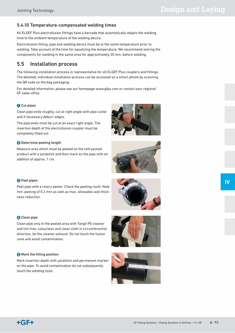
GF Piping Systems – Piping Systems in Utilities – (11.18) 4 · 93
Design and LayingJointingTechnology
IV
5.4.10 Temperature-compensated welding times
AllELGEFPluselectrofusionfittingshaveabarcodethatautomaticallyadaptsthewelding
timetotheambienttemperatureoftheweldingdevice.
Electrofusionfitting,pipeandweldingdevicemustbeatthesametemperaturepriorto
welding.Takeaccountofthetimeforequalizingthetemperature.Werecommendstoringthe
componentsforweldinginthesameareaforapproximately20min.beforewelding.
5.5 Installation processThefollowinginstallationprocessisrepresentativeforallELGEFPluscouplersandfittings.
The detailed, individual installation process can be accessed on a smart phone by scanning
theQRcodeonthebagpackaging.
Fordetailedinformation,pleaseseeourhomepagewww.gfps.comorcontactyourregionalGFsalesoffice.
a Cut pipes
Cleanpipeendsroughly,cutatrightanglewithpipecutter
and if necessary deburr edges.
The pipe ends must be cut at an exact right angle. The
insertion depth of the electrofusion coupler must be
completelyfilledout.
s Determine peeling length
Measureareawhichmustbepeeledonthestillpacked
productwithayardstickandthenmarkonthepipewithan
addition of approx. 1 cm.
d Peel pipes
Peelpipewitharotarypeeler.Checkthepeelingresilt.Note
min.peelingof0.2mmaswellasmax.allowablewallthick-
ness reduction.
f Clean pipe
CleanpipeonlyinthepeeledareawithTangitPEcleaner
andlint-free,colourlessandcleanclothincircumferential
direction, let the cleaner exhaust. Do not touch the fusion
zone and avoid contamination.
g Mark the fi tting position
Markinsertiondepthwithyardstickandpermanentmarker
onthepipe.Toavoidcontaminationdonotsubsequently
touchtheweldingzone.
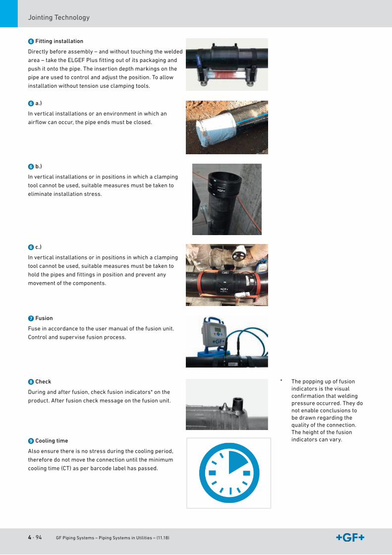
4 · 94 GF Piping Systems – Piping Systems in Utilities – (11.18)
JointingTechnology
h Fitting installation
Directlybeforeassembly–andwithouttouchingthewelded
area–taketheELGEFPlusfittingoutofitspackagingand
pushitontothepipe.Theinsertiondepthmarkingsonthe
pipeareusedtocontrolandadjusttheposition.Toallow
installationwithouttensionuseclampingtools.
h a.)
Inverticalinstallationsoranenvironmentinwhichan
airflowcanoccur,thepipeendsmustbeclosed.
h b.)
Inverticalinstallationsorinpositionsinwhichaclamping
toolcannotbeused,suitablemeasuresmustbetakento
eliminate installation stress.
h c.)
Inverticalinstallationsorinpositionsinwhichaclamping
toolcannotbeused,suitablemeasuresmustbetakento
holdthepipesandfittingsinpositionandpreventany
movement of the components.
j Fusion
Fuse in accordance to the user manual of the fusion unit.
Control and supervise fusion process.
k Check
Duringandafterfusion,checkfusionindicators*onthe
product.Afterfusioncheckmessageonthefusionunit.
l Cooling time
Also ensure there is no stress during the cooling period,
therefore do not move the connection until the minimum
cooling time (CT) as per barcode label has passed.
* The popping up of fusion indicators is the visual confirmationthatweldingpressure occurred. They do not enable conclusions to bedrawnregardingthequalityoftheconnection.The height of the fusion indicators can vary.
GF Piping Systems – Piping Systems in Utilities – (11.18) 4 · 95
Design and LayingJointingTechnology
IV
5.6 Cooling times ELGEF Plus coupler & fittingsAfter the fusion process, our MSA electrofusion units directly display the cooling time after
whichtheclampingtoolcanberemoved.Ifotherelectrofusionunitsareused,thecooling
timeuptoremovaloftheclampingtoolisindicatedonthebarcodelabelwith“CT”.Afterthis
coolingtime,theweldedconnectioncanbemoved.
Thelongercoolingtimesinthetablebelowapplyfortheload-bearingcapacityforthe
tightness test.
T4.12 Cooling times for ELGEF Plus coupler and fittings
dn
(mm)Remove clamping tool(min.)
Tightness test*
STP ≤ 6 bar(min.)
STP ≤ 18 bar(min.)
20-63 6 10 3075-110 10 20 60
125-160 20 30 75180-225 20 45 90250-315 30 60 150355-400 60 120 180450-630 60 150 210710-800 90 150 240900-1200 60 150 240
Thecoolingtimespecifieshowlongittakesfortheweldedconnectiontocooltoa
corresponding reference temperature. The reference temperature is a measure for the
stabilityoftheconnectionandthuswhatloads/stressestheconnectioncanbesubjectedto.
For removal of the clamping tool, Georg Fischer uses a ref. temp. of 110 °C, a ref. temp. of 80
°C for an internal pressure of 6 bar and a ref. temp. of 20 °C (ambient temperature) for an
internal pressure of 18 bar.
5.7 Cooling times for ELGEF Plus saddles & PVTsAfter the fusion process, our MSA electrofusion units directly display the cooling time after
whichtheweldedconnectioncanbemechanicallyloaded.Ifotherelectrofusiondevicesare
used, the cooling time up to removal of the clamping tool is indicated on the barcode label
with“CT”.Afterthiscoolingunits,theweldedconnectioncanbemoved.Thelongercooling
timesinthetablebelowapplyfortheload-bearingcapacityforthetightnesstest.
T4.13 Minimum cooling time for ELGEF Plus saddles and pressure tapping valves (PTVs)
dn
(mm)Mechanical load,Pressureless tapping
(min.)
Tightness test / tapping under operating pressure
STP ≤ 6 bar(min.)
STP ≤ 18 bar(min.)
40, 50 Monobloc 10 20 3063-160Monobloc 20 30 90
63-400Duobloc 20,30* 30 90110-630branchsaddle 30 45 90Branch saddle topload315-1000xoutlet160/225
45 90 180
Branch saddle topload500-2000xoutlet315/500
60 120 240
Thecoolingtimespecifieshowlongittakesfortheweldedconnectiontocooltoa
corresponding reference temperature. The reference temperature is a measure for the
stabilityoftheconnectionandthuswhatloads/stressestheconnectioncanbesubjectedto.
For removal of the clamping tool, Georg Fischer uses a ref. temp. of 110 °C, a ref. temp. of 80
°C for an internal pressure of 6 bar and a ref. temp. of 20 °C (ambient temperature) for an
internal pressure of 18 bar.
* Includingthecoolingtimetoremovalofclampingtool;STP = system test pres-sure.
* With injection molded bottom part for dn110 and dn160
STP System test pressure
4 · 96 GF Piping Systems – Piping Systems in Utilities – (11.18)
JointingTechnology
5.8 Mechanical joints
Overview
OfthemanydiversesolutionsofferedbyGFPipingSystemsformechanicaljoints,the
followingtableoffersinformationontheconventionalmethodsusedinindustrialpiping
systemconstruction:
Figure Connections typre Gasket Connection of plastic with
Transitionadapterwiththread
PTFETape Plastic/metal
Flange connection O-ring Plastic or metalProfileseal
MULTI/JOINT®Widerangefitting
Special seal Suitable for all pipe materials
iJOINTCompressionfitting
Lip seal plastic
PRIMOFITCompressionfitting
Profileseal Plastic or metal
Universal coupling Special seal Plastic or metal
T4.14 Overview of mechanical connections
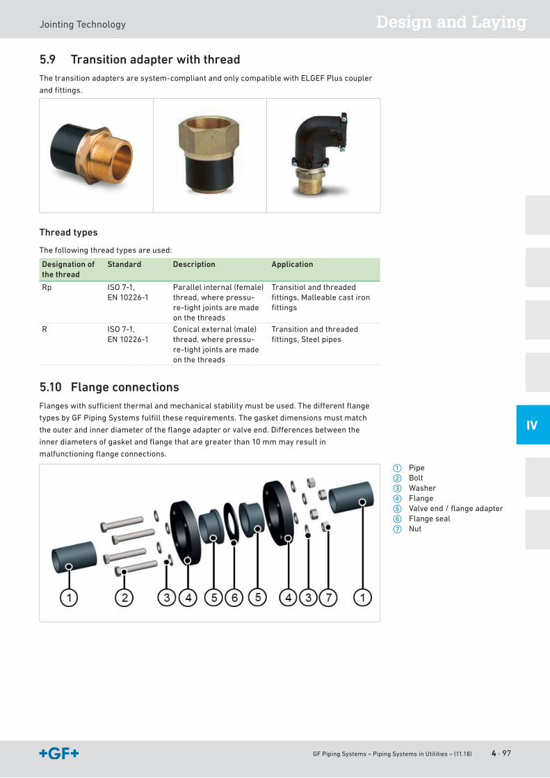
GF Piping Systems – Piping Systems in Utilities – (11.18) 4 · 97
Design and LayingJointingTechnology
IV
5.9 Transition adapter with threadThetransitionadaptersaresystem-compliantandonlycompatiblewithELGEFPluscoupler
andfittings.
Thread types
Thefollowingthreadtypesareused:
Designation of the thread
Standard Description Application
Rp ISO7-1,EN10226-1
Parallel internal (female) thread,wherepressu-re-tightjointsaremadeon the threads
Transitiol and threaded fittings,Malleablecastironfittings
R ISO7-1,EN10226-1
Conical external (male) thread,wherepressu-re-tightjointsaremadeon the threads
Transition and threaded fittings,Steelpipes
5.10 Flange connectionsFlangeswithsufficientthermalandmechanicalstabilitymustbeused.Thedifferentflange
typesbyGFPipingSystemsfulfilltheserequirements.Thegasketdimensionsmustmatch
theouterandinnerdiameteroftheflangeadapterorvalveend.Differencesbetweenthe
innerdiametersofgasketandflangethataregreaterthan10mmmayresultin
malfunctioningflangeconnections.
a Pipes Boltd Washerf Flangeg Valveend/flangeadapterh Flange sealj Nut
4 · 98 GF Piping Systems – Piping Systems in Utilities – (11.18)
JointingTechnology
5.10.1 Comparison of fl ange connections
Flange connection Properties
PP-Vflange • Corrosion-freeall-plasticflangemadeofpolypropylenePP-GF30(fiber-glassreinforced)
• Highchemicalresistance(hydrolysis-resistant)• Maximumpossiblebreakresistanceduetoelasticity(deformsifitis
tightened too much)• Use for ambient temperatures up to 80 °C• The temperature of the medium is restricted by the material of the
plastic piping system• UV-stabilized• Withintegratedbolt-fixing• Self-centeringaidfortheflangesontheflangeadapter• Symmetricdesignallowsassemblyoneitherside:A„reverse“
installation is never possible. All important information is readable• V-groove(patented)• Evendistributionofforcesacrosstheflange(preserveslifeexpec-
tancy of components)• Supportsalonger-lastingtorqueforasafejoint
PPsteelflange • Veryrobustandstiffduetothesteelinlay• Corrosion-freeplasticflangemadeofpolypropylenePP-GF30
(fiber-glassreinforced)withsteelinlay• Highchemicalresistance(hydrolysis-resistant)• Maximum ambient temperature 80 °C• UV-stabilized
Steel, galvanized • ExtremelyrobustandrigidBlindflange • CombinationofabackingflangeandaPE100endblank.
• Combinesendblanksinthedimensionsd63tod315withthePP-Vbackingflange.
• Dimensionsd355tod630arecombinedusingaloose-typeflangemadefromPPwithasteelinsert.
• Withtheblankingflangeset,thepipingsystemcanbeclosedoffusing the same material.
• Ifthepipingsystemisextended,thebackingflangecanbeusedagain,cuttingdownonadditionalcosts.
• Suitable for pressure piping• Easyassemblyoftheblankflangeset:Theendblankiscenteredon
theinnerdiameterofthebackingflange.
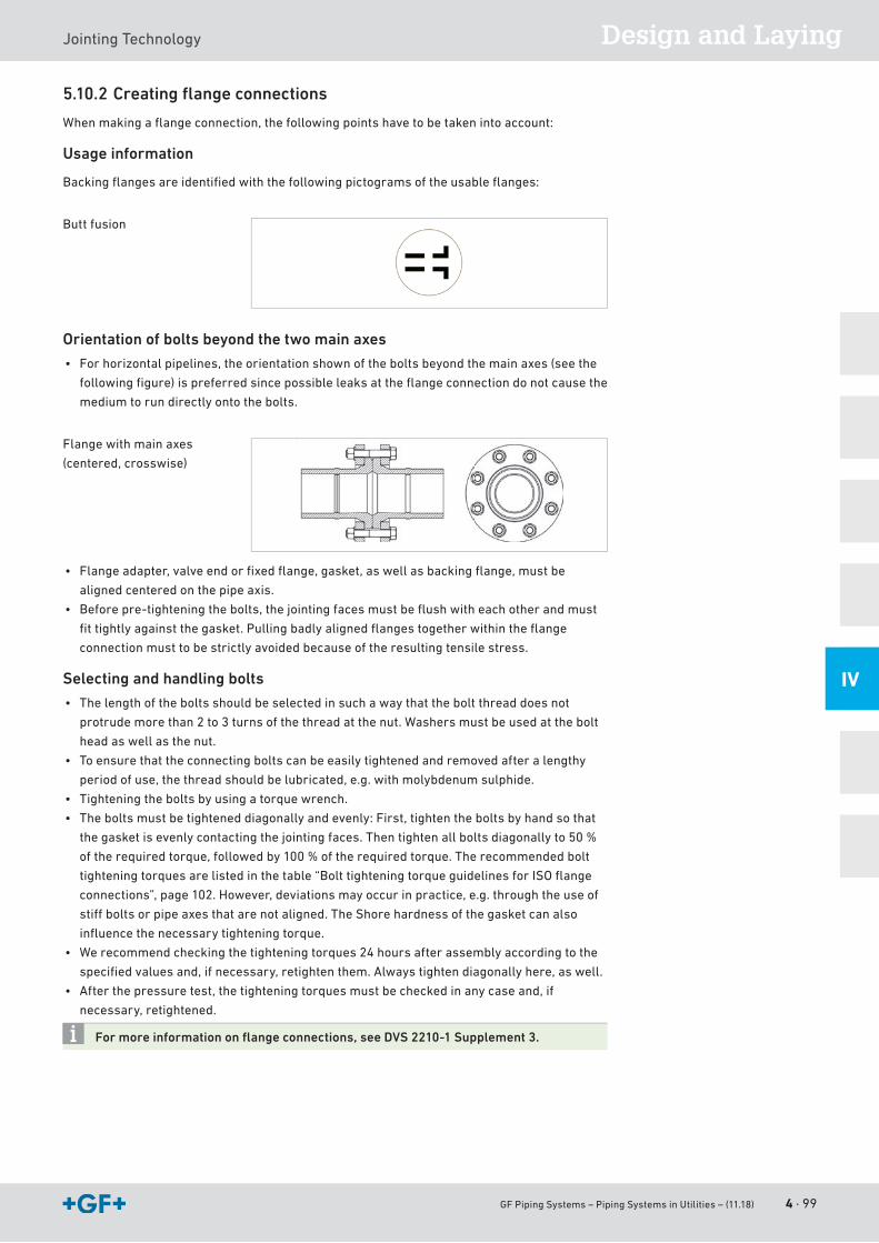
GF Piping Systems – Piping Systems in Utilities – (11.18) 4 · 99
Design and LayingJointingTechnology
IV
5.10.2 Creating fl ange connections
Whenmakingaflangeconnection,thefollowingpointshavetobetakenintoaccount:
Usage information
Backingflangesareidentifiedwiththefollowingpictogramsoftheusableflanges:
Butt fusion
Orientation of bolts beyond the two main axes
• Forhorizontalpipelines,theorientationshownoftheboltsbeyondthemainaxes(seethe
followingfigure)ispreferredsincepossibleleaksattheflangeconnectiondonotcausethe
medium to run directly onto the bolts.
Flangewithmainaxes
(centered,crosswise)
• Flangeadapter,valveendorfixedflange,gasket,aswellasbackingflange,mustbe
aligned centered on the pipe axis.
• Beforepre-tighteningthebolts,thejointingfacesmustbeflushwitheachotherandmust
fittightlyagainstthegasket.Pullingbadlyalignedflangestogetherwithintheflange
connection must to be strictly avoided because of the resulting tensile stress.
Selecting and handling bolts
• Thelengthoftheboltsshouldbeselectedinsuchawaythattheboltthreaddoesnot
protrudemorethan2to3turnsofthethreadatthenut.Washersmustbeusedatthebolt
headaswellasthenut.
• To ensure that the connecting bolts can be easily tightened and removed after a lengthy
periodofuse,thethreadshouldbelubricated,e.g.withmolybdenumsulphide.
• Tighteningtheboltsbyusingatorquewrench.
• Theboltsmustbetighteneddiagonallyandevenly:First,tightentheboltsbyhandsothat
thegasketisevenlycontactingthejointingfaces.Thentightenallboltsdiagonallyto50%
oftherequiredtorque,followedby100%oftherequiredtorque.Therecommendedbolt
tighteningtorquesarelistedinthetable“BolttighteningtorqueguidelinesforISOflange
connections”,page102.However,deviationsmayoccurinpractice,e.g.throughtheuseof
stiffboltsorpipeaxesthatarenotaligned.TheShorehardnessofthegasketcanalso
influencethenecessarytighteningtorque.
• Werecommendcheckingthetighteningtorques24hoursafterassemblyaccordingtothe
specifiedvaluesand,ifnecessary,retightenthem.Alwaystightendiagonallyhere,aswell.
• Afterthepressuretest,thetighteningtorquesmustbecheckedinanycaseand,if
necessary, retightened.
For more information on fl ange connections, see DVS 2210-1 Supplement 3.

4 · 100 GF Piping Systems – Piping Systems in Utilities – (11.18)
JointingTechnology
Tightening the bolts using a torque wrench
However,deviationsmayoccurinpractice,e.g.throughtheuseofstiffboltsorpipeaxesthat
arenotaligned.TheShorehardnessofthegasketcanalsoinfluencethenecessarytightening
torque.
In the area of flexible sections and expansion loops, no bolt connections or flange connections should be used since the bending stress may cause leaks.
5.10.3 Bolt tightening torque guidelines for metric (ISO) flange connections with PP-V, PP- steel and PVC flanges
TheindicatedtorquesarerecommendedbyGFPipingSystems.Thesetorquesalreadyensure
asufficienttightnessoftheflangeconnection.TheydeviatefromthedataintheDVS2210-1
Supplement3,whicharetobeunderstoodasupperlimits.Theindividualcomponentsofthe
flangeconnection(valveends,flangeadapters,flanges)byGFPipingsystemsare
dimensioned for these upper limits.
Pipe outer diameter dn (mm)
Nominal diameter DN (mm)
Bolt tightening torque MD (Nm)
Flat ring maximum pressure10 bar / 40 °C
Profile gasket maximum pressure16 bar
O ring maximum pressure 16 bar
d16 DN10 10 10 10
d20 DN15 10 10 10d25 DN20 10 10 10d32 DN25 15 10 10d40 DN32 20 15 15d50 DN40 25 15 15d63 DN50 35 20 20d75 DN65 50 25 25d90 DN80 30 15 15d110, 125 DN100 35 20 20d140 DN125 45 25 25d160, 180 DN150 60 35 30d200, 225 DN200 701) 45 35d250, 280 DN250 651) 35 30d315 DN300 901) 50 40d355 DN350 901) 50 -d400 DN400 1001) 60 -d450, 500 DN450,DN500 1901) 70 -d560,630 DN600 2201) 90 -
Please observe the special bolt tightening torques listed for butterfly valves DN25 and
DN300. See also the section “Planning fundamentals for butterfly valves, hand-
operated”.
1) Maximum operating pressure6 bar
Bolttighteningtorque guidelinesforISOflange connections
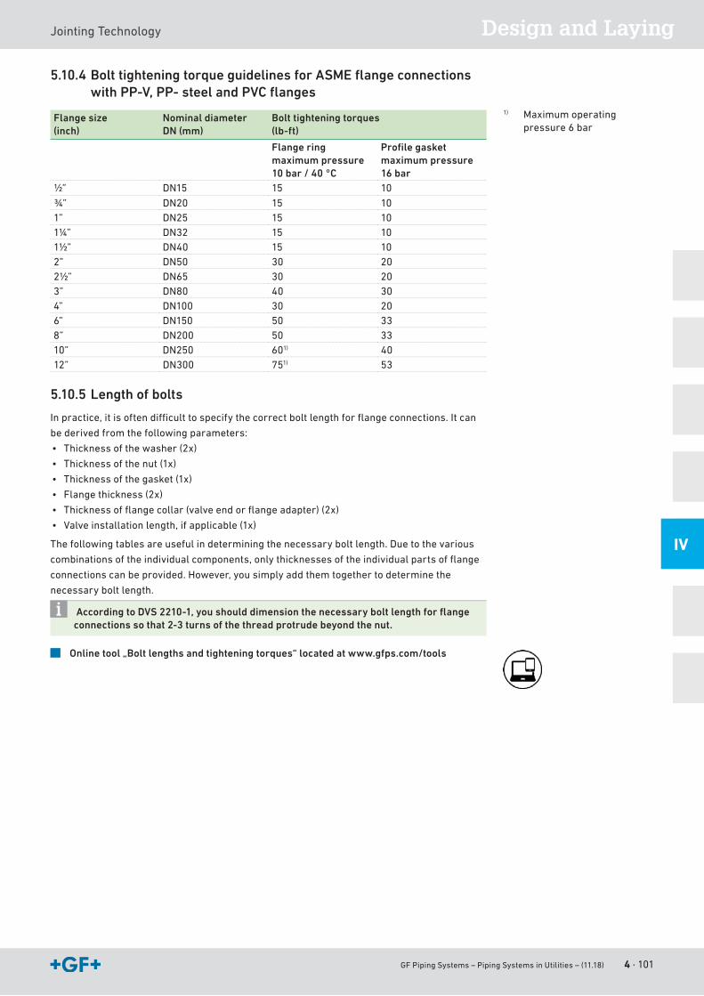
GF Piping Systems – Piping Systems in Utilities – (11.18) 4 · 101
Design and LayingJointingTechnology
IV
5.10.4 Bolt tightening torque guidelines for ASME fl ange connections with PP-V, PP- steel and PVC fl anges
Flange size(inch)
Nominal diameterDN (mm)
Bolt tightening torques(lb-ft)
Flange ring maximum pressure 10 bar / 40 °C
Profi le gasket maximum pressure 16 bar
½” DN15 15 10
¾” DN20 15 101” DN25 15 101¼” DN32 15 101½” DN40 15 102” DN50 30 202½” DN65 30 203” DN80 40 304” DN100 30 206” DN150 50 338” DN200 50 3310” DN250 601) 4012” DN300 751) 53
5.10.5 Length of bolts
Inpractice,itisoftendifficulttospecifythecorrectboltlengthforflangeconnections.Itcan
bederivedfromthefollowingparameters:
• Thicknessofthewasher(2x)
• Thicknessofthenut(1x)
• Thicknessofthegasket(1x)
• Flangethickness(2x)
• Thicknessofflangecollar(valveendorflangeadapter)(2x)
• Valveinstallationlength,ifapplicable(1x)
Thefollowingtablesareusefulindeterminingthenecessaryboltlength.Duetothevarious
combinationsoftheindividualcomponents,onlythicknessesoftheindividualpartsofflange
connectionscanbeprovided.However,yousimplyaddthemtogethertodeterminethe
necessary bolt length.
According to DVS 2210-1, you should dimension the necessary bolt length for fl ange connections so that 2-3 turns of the thread protrude beyond the nut.
Online tool „Bolt lengths and tightening torques“ located at www.gfps.com/tools
1) Maximum operating pressure6 bar
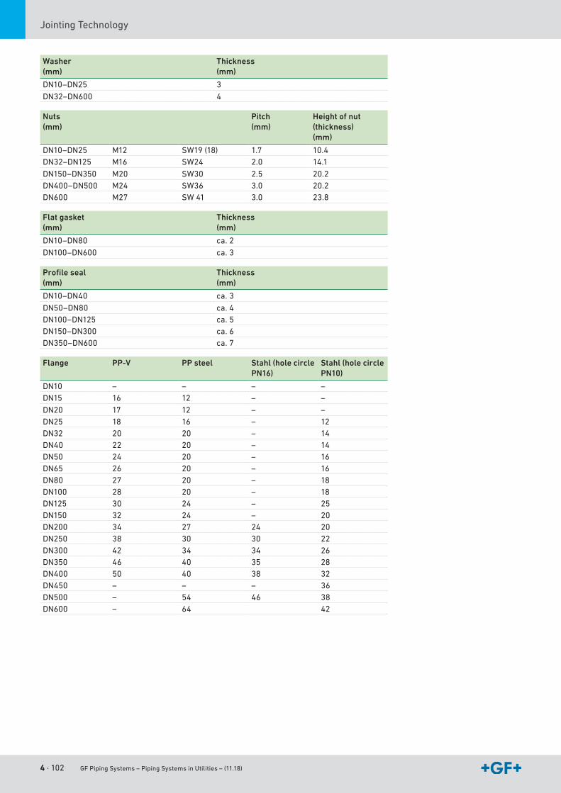
4 · 102 GF Piping Systems – Piping Systems in Utilities – (11.18)
JointingTechnology
Washer(mm)
Thickness(mm)
DN10–DN25 3
DN32–DN600 4
Nuts(mm)
Pitch(mm)
Height of nut (thickness)(mm)
DN10–DN25 M12 SW19(18) 1.7 10.4 DN32–DN125 M16 SW24 2.0 14.1
DN150–DN350 M20 SW30 2.5 20.2 DN400–DN500 M24 SW36 3.0 20.2 DN600 M27 SW 41 3.0 23.8
Flat gasket(mm)
Thickness(mm)
DN10–DN80 ca. 2
DN100–DN600 ca.3
Profile seal(mm)
Thickness(mm)
DN10–DN40 ca.3
DN50–DN80 ca. 4DN100–DN125 ca. 5DN150–DN300 ca. 6DN350–DN600 ca. 7
Flange PP-V PP steel Stahl (hole circle PN16)
Stahl (hole circle PN10)
DN10 – – – –DN15 16 12 – –
DN20 17 12 – –DN25 18 16 – 12DN32 20 20 – 14DN40 22 20 – 14DN50 24 20 – 16DN65 26 20 – 16DN80 27 20 – 18DN100 28 20 – 18DN125 30 24 – 25DN150 32 24 – 20DN200 34 27 24 20DN250 38 30 30 22DN300 42 34 34 26DN350 46 40 35 28DN400 50 40 38 32DN450 – – – 36DN500 – 54 46 38DN600 – 64 42
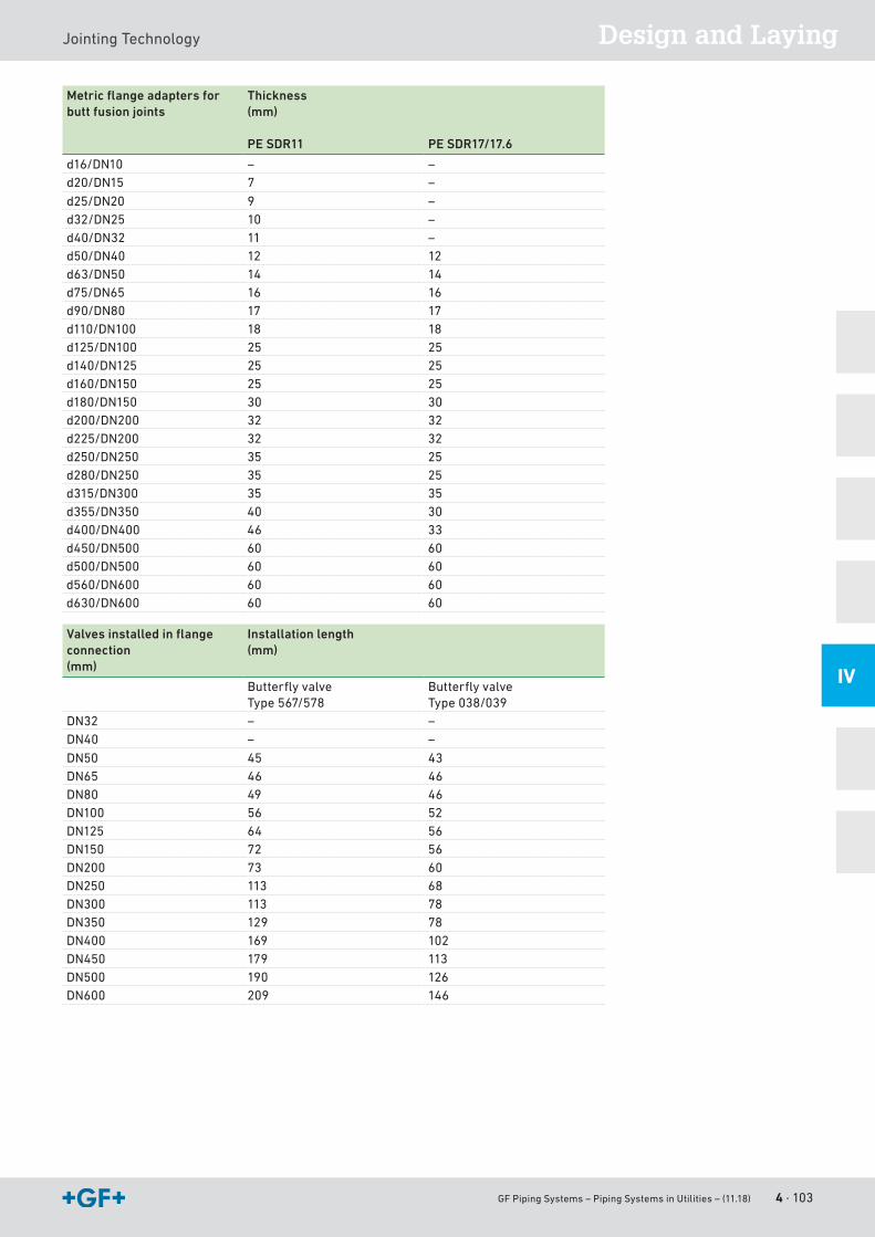
GF Piping Systems – Piping Systems in Utilities – (11.18) 4 · 103
Design and LayingJointingTechnology
IV
Metric flange adapters for butt fusion joints
Thickness (mm)
PE SDR11 PE SDR17/17.6
d16/DN10 – –d20/DN15 7 –
d25/DN20 9 –d32/DN25 10 –d40/DN32 11 –d50/DN40 12 12 d63/DN50 14 14 d75/DN65 16 16 d90/DN80 17 17 d110/DN100 18 18 d125/DN100 25 25 d140/DN125 25 25 d160/DN150 25 25 d180/DN150 30 30d200/DN200 32 32d225/DN200 32 32d250/DN250 35 25 d280/DN250 35 25 d315/DN300 35 35d355/DN350 40 30d400/DN400 46 33d450/DN500 60 60 d500/DN500 60 60 d560/DN600 60 60 d630/DN600 60 60
Valves installed in flange connection (mm)
Installation length(mm)
ButterflyvalveType567/578
ButterflyvalveType038/039
DN32 – –DN40 – –
DN50 45 43DN65 46 46 DN80 49 46 DN100 56 52 DN125 64 56 DN150 72 56 DN200 73 60 DN250 113 68 DN300 113 78 DN350 129 78DN400 169 102DN450 179 113DN500 190 126DN600 209 146
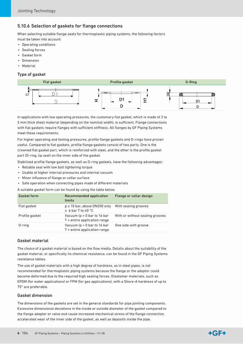
4 · 104 GF Piping Systems – Piping Systems in Utilities – (11.18)
JointingTechnology
5.10.6 Selection of gaskets for fl ange connections
Whenselectingsuitableflangesealsforthermoplasticpipingsystems,thefollowingfactors
mustbetakenintoaccount:
• Operatingconditions
• Sealing forces
• Gasketform
• Dimension
• Material
Type of gasket
Flat gasket Profi le gasket O-Ring
Inapplicationswithlowoperatingpressures,thecustomaryflatgasket,whichismadeof2to
5mmthicksheetmaterial(dependingonthenominalwidth),issufficient.Flangeconnections
withflatgasketsrequireflangeswithsufficientstiffness.AllflangesbyGFPipingSystems
meettheserequirements.
Forhigheroperatingandtestingpressures,profileflangegasketsandO-ringshaveproven
useful.Comparedtoflatgaskets,profileflangegasketsconsistoftwoparts.Oneisthe
crownedflatgasketpart,whichisreinforcedwithsteel,andtheotheristheprofilegasket
part(O-ring,lipseal)ontheinnersideofthegasket.
Stabilizedprofileflangegaskets,aswellasO-ringgaskets,havethefollowingadvantages:
• Reliablesealwithlowbolttighteningtorque
• Usable at higher internal pressures and internal vacuum
• Minorinfluenceofflangeorcollarsurface
• Safeoperationwhenconnectingpipesmadeofdifferentmaterials
Asuitablegasketformcanbefoundbyusingthetablebelow.
Gasket form Recommended application limits
Flange or collar design
Flatgasket p≤10bar,aboveDN200only≤6barTto40°C
With sealing grooves
Profilegasket Vacuum(p=0barto16barT = entire application range
Withorwithoutsealinggrooves
O-ring Vacuum(p=0barto16barT = entire application range
Onesidewithgroove
Gasket material
Thechoiceofagasketmaterialisbasedontheflowmedia.Detailsaboutthesuitabilityofthe
gasketmaterial,orspecificallyitschemicalresistance,canbefoundintheGFPipingSystems
resistance tables.
Theuseofgasketmaterialswithahighdegreeofhardness,asinsteelpipes,isnot
recommendedforthermoplasticpipingsystemsbecausetheflangeortheadaptorcould
becomedeformedduetotherequiredhighsealingforces.Elastomermaterials,suchas
EPDM(forwaterapplications)orFPM(forgasapplications),withaShore-Ahardnessofupto
75° are preferable.
Gasket dimension
Thedimensionsofthegasketsaresetinthegeneralstandardsforpipejointingcomponents.
Excessivedimensionaldeviationsintheinsideoroutsidediameterofthegasketcomparedto
theflangeadapterorvalveendcauseincreasedmechanicalstressoftheflangeconnection,
acceleratedwearoftheinnersideofthegasket,aswellasdepositsinsidethepipe.
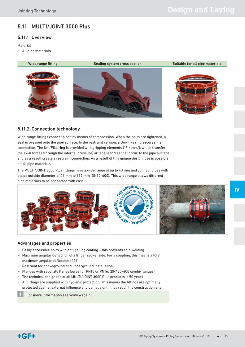
GF Piping Systems – Piping Systems in Utilities – (11.18) 4 · 105
Design and LayingJointingTechnology
IV
5.11 MULTI/JOINT 3000 Plus
5.11.1 Overview
Material
• All pipe materials
Wide range fi tting Sealing system cross section Suitable for all pipe materials
5.11.2 Connection technology
Widerangefittingsconnectpipesbymeansofcompression.Whentheboltsaretightened,a
sealispressedontothepipesurface.Intherestraintversion,aUni/Fiksringsecuresthe
connection.TheUni/Fiksringisprovidedwithgrippingelements(“Fiksers”),whichtransfer
the axial forces (through the internal pressure) or tensile forces that occur, to the pipe surface
andasaresultcreatearestraintconnection.Asaresultofthisuniquedesign,useispossible
on all pipe materials.
TheMULTI/JOINT3000Plusfittingshaveawiderangeofupto43mmandconnectpipeswith
apipeoutsidediameterof46mmto637mm(DN50-600).Thiswiderangeallowsdifferent
pipematerialstobeconnectedwithease.
Advantages and properties
• Easilyaccessibleboltswithantigallingcoating–thispreventscoldwelding
• Maximumangulardeflectionof±8˚persocketside.Foracoupling,thismeansatotal
maximumangulardeflectionof16˚
• Restraint for aboveground and underground installation
• FlangeswithseparateflangeboresforPN10orPN16.(DN425-600combi-flanges)
• ThetechnicaldesignlifeofallMULTI/JOINT3000Plusproductsis50years
• Allfittingsaresuppliedwithhygienicprotection.Thismeansthefittingsareoptimally
protectedagainstexternalinfluenceanddamageuntiltheyreachtheconstructionsite
For more information see www.waga.nl

4 · 106 GF Piping Systems – Piping Systems in Utilities – (11.18)
JointingTechnology
5.12 iJOINTCompression fitting Connection cross-section Easy assembly
5.12.1 Connection technology
TheiJOINTcompressionfittingconnectsPEpipesbycompressingtheseal.Whenthenuts
are tightened, a lip seal is pressed onto the pipe surface. A grip ring secures the connection.
The grip ring transfers the axial forces (through the internal pressure) or tensile forces that
occur to the pipe surface and as a result creates restraint.
Body and thrust ring Properties
Body and thrust ring UV-stabilizedpolypropyleneimpact-resistantcopolymerwithhighlong-termageresistanceinaccordancewithISO9080.
Coupling nut UV-stabilizedbluepolypropyleneimpact-resistantcopolymer
Clamp ring Polyoxymethylene(POM)Seal NBRlipsealtod63
NBRprofilesealfromd75tod110Reinforcing ring (for internal thread)
StainlesssteelAISI430
Thread Externalthreadconical/internalthreadcylindricalin accordancewithISO7
Advantages and properties
• Forwaterinstallationsupto16bar
• Temperaturerange:-10°Cto+45°C
• Fast and easy installation
• Nopipepreparationrequired(e.g.chamfering)
• Nospecialtoolsrequired
• Thespeciallipgasketallowsasmootpipeinsertionandprovidesatthesametimethebest
possible tightness also in case of out of roundness or slightly scratched pipes.
• Reusable
For more information on using iJOINT, see www.gfps.com
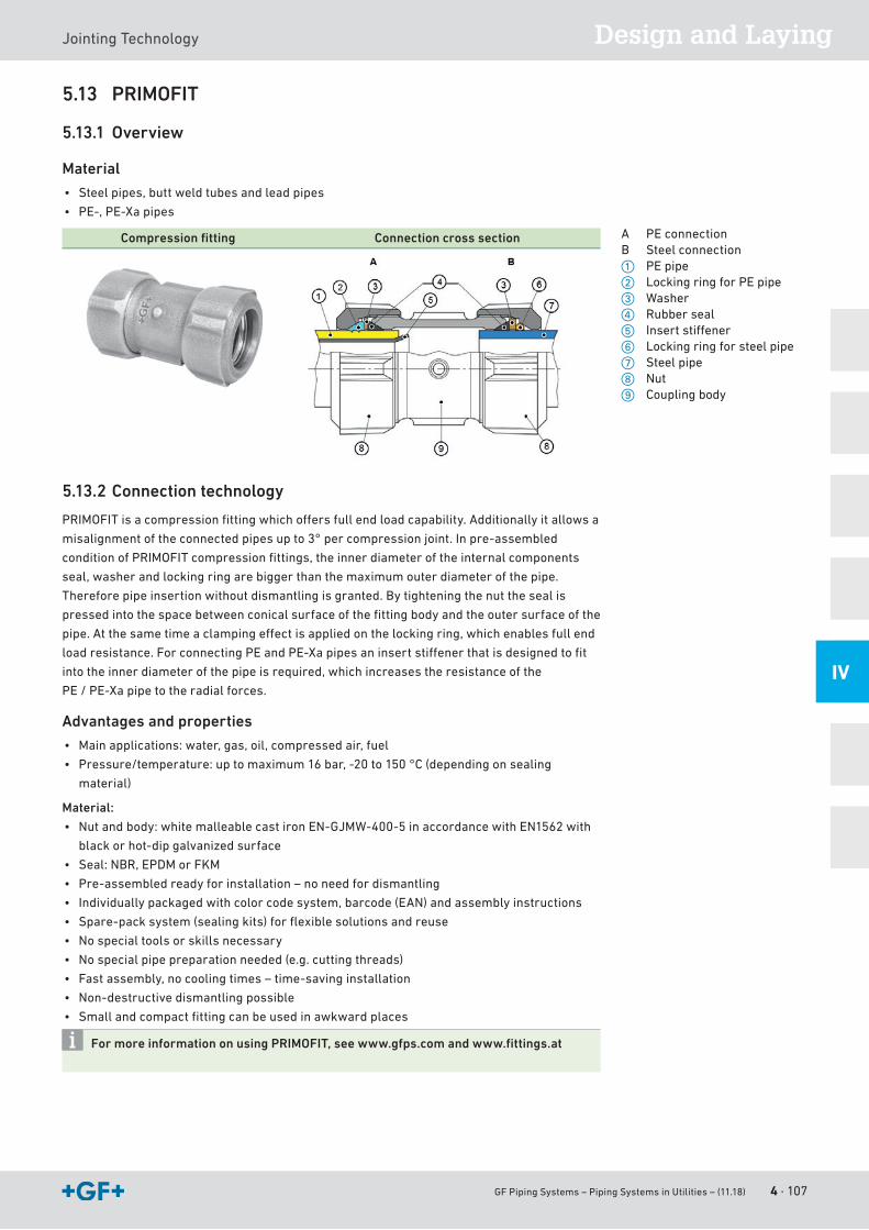
GF Piping Systems – Piping Systems in Utilities – (11.18) 4 · 107
Design and LayingJointingTechnology
IV
5.13 PRIMOFIT
5.13.1 Overview
Material
• Steelpipes,buttweldtubesandleadpipes
• PE-,PE-Xapipes
Compression fi tting Connection cross section
5.13.2 Connection technology
PRIMOFITisacompressionfittingwhichoffersfullendloadcapability.Additionallyitallowsa
misalignmentoftheconnectedpipesupto3°percompressionjoint.Inpre-assembled
conditionofPRIMOFITcompressionfittings,theinnerdiameteroftheinternalcomponents
seal,washerandlockingringarebiggerthanthemaximumouterdiameterofthepipe.
Thereforepipeinsertionwithoutdismantlingisgranted.Bytighteningthenutthesealis
pressedintothespacebetweenconicalsurfaceofthefittingbodyandtheoutersurfaceofthe
pipe.Atthesametimeaclampingeffectisappliedonthelockingring,whichenablesfullend
loadresistance.ForconnectingPEandPE-Xapipesaninsertstiffenerthatisdesignedtofit
intotheinnerdiameterofthepipeisrequired,whichincreasestheresistanceofthe
PE / PE-Xapipetotheradialforces.
Advantages and properties
• Mainapplications:water,gas,oil,compressedair,fuel
• Pressure/temperature:uptomaximum16bar,-20to150°C(dependingonsealing
material)
Material:
• Nutandbody:whitemalleablecastironEN-GJMW-400-5inaccordancewithEN1562with
blackorhot-dipgalvanizedsurface
• Seal:NBR,EPDMorFKM
• Pre-assembledreadyforinstallation–noneedfordismantling
• Individuallypackagedwithcolorcodesystem,barcode(EAN)andassemblyinstructions
• Spare-packsystem(sealingkits)forflexiblesolutionsandreuse
• Nospecialtoolsorskillsnecessary
• Nospecialpipepreparationneeded(e.g.cuttingthreads)
• Fastassembly,nocoolingtimes–time-savinginstallation
• Non-destructivedismantlingpossible
• Smallandcompactfittingcanbeusedinawkwardplaces
For more information on using PRIMOFIT, see www.gfps.com and www.fi ttings.at
A PEconnectionB Steel connectiona PEpipes LockingringforPEpiped Washerf Rubber sealg Insertstiffenerh Lockingringforsteelpipej Steel pipek Nutl Coupling body
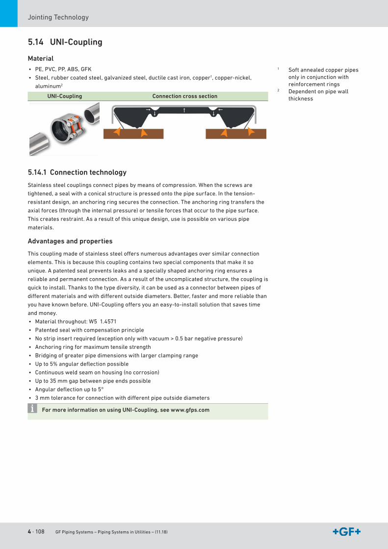
4 · 108 GF Piping Systems – Piping Systems in Utilities – (11.18)
JointingTechnology
5.14 UNI-Coupling
Material
• PE,PVC,PP,ABS,GFK
• Steel, rubber coated steel, galvanized steel, ductile cast iron, copper1,copper-nickel,
aluminum2
UNI-Coupling Connection cross section
5.14.1 Connection technology
Stainlesssteelcouplingsconnectpipesbymeansofcompression.Whenthescrewsare
tightened,asealwithaconicalstructureispressedontothepipesurface.Inthetension-
resistant design, an anchoring ring secures the connection. The anchoring ring transfers the
axial forces (through the internal pressure) or tensile forces that occur to the pipe surface.
Thiscreatesrestraint.Asaresultofthisuniquedesign,useispossibleonvariouspipe
materials.
Advantages and properties
Thiscouplingmadeofstainlesssteeloffersnumerousadvantagesoversimilarconnection
elements.Thisisbecausethiscouplingcontainstwospecialcomponentsthatmakeitso
unique.Apatentedsealpreventsleaksandaspeciallyshapedanchoringringensuresa
reliable and permanent connection. As a result of the uncomplicated structure, the coupling is
quicktoinstall.Thankstothetypediversity,itcanbeusedasaconnectorbetweenpipesof
differentmaterialsandwithdifferentoutsidediameters.Better,fasterandmorereliablethan
youhaveknownbefore.UNI-Couplingoffersyouaneasy-to-installsolutionthatsavestime
and money.
• Materialthroughout:W51.4571
• Patentedsealwithcompensationprinciple
• Nostripinsertrequired(exceptiononlywithvacuum>0.5barnegativepressure)
• Anchoring ring for maximum tensile strength
• Bridgingofgreaterpipedimensionswithlargerclampingrange
• Upto5%angulardeflectionpossible
• Continuousweldseamonhousing(nocorrosion)
• Upto35mmgapbetweenpipeendspossible
• Angulardeflectionupto5°
• 3mmtoleranceforconnectionwithdifferentpipeoutsidediameters
For more information on using UNI-Coupling, see www.gfps.com
1 Soft annealed copper pipes onlyinconjunctionwithreinforcement rings
2 Dependentonpipewallthickness
GF Piping Systems – Piping Systems in Utilities – (11.18) 5 · 109
ELGEF Plus System
Content
1 The ELGEF Plus electrofusion system ................................................................................. 1101.1 Quality . . . . . . . . . . . . . . . . . . . . . . . . . . . . . . . . . . . . . . . . . . . . . . . . . . . . . . . . . . . . . . . . . . . . . . . . . . . . . . . . . . . . . . . . . . . . . . . . . . . . . . . . . . . . . . . . . . . . . . . . . . . . . . . . . . . . . . . . . . . . . . . . . . . . . . . . . . . . . . . . 110
1.2 Field of application . . . . . . . . . . . . . . . . . . . . . . . . . . . . . . . . . . . . . . . . . . . . . . . . . . . . . . . . . . . . . . . . . . . . . . . . . . . . . . . . . . . . . . . . . . . . . . . . . . . . . . . . . . . . . . . . . . . . . . . . . . . . . . . . . . . . . . . . . . 111
1.3 Identification . . . . . . . . . . . . . . . . . . . . . . . . . . . . . . . . . . . . . . . . . . . . . . . . . . . . . . . . . . . . . . . . . . . . . . . . . . . . . . . . . . . . . . . . . . . . . . . . . . . . . . . . . . . . . . . . . . . . . . . . . . . . . . . . . . . . . . . . . . . . . . . . . . . . . 112
1.4 CAD library . . . . . . . . . . . . . . . . . . . . . . . . . . . . . . . . . . . . . . . . . . . . . . . . . . . . . . . . . . . . . . . . . . . . . . . . . . . . . . . . . . . . . . . . . . . . . . . . . . . . . . . . . . . . . . . . . . . . . . . . . . . . . . . . . . . . . . . . . . . . . . . . . . . . . . . . 115
2 Couplersandfittings ............................................................................................................. 1162.1 System advantages of ELGEF Plus couplers . . . . . . . . . . . . . . . . . . . . . . . . . . . . . . . . . . . . . . . . . . . . . . . . . . . . . . . . . . . . . . . . . . . . . . . . . . . . . . . . . . . . . . . . . . . . . . 116
2.2 SystemadvantagesofELGEFPlusfittings . . . . . . . . . . . . . . . . . . . . . . . . . . . . . . . . . . . . . . . . . . . . . . . . . . . . . . . . . . . . . . . . . . . . . . . . . . . . . . . . . . . . . . . . . . . . . . . . . 117
2.3 System advantages of ELGEF Plus transition adaptors . . . . . . . . . . . . . . . . . . . . . . . . . . . . . . . . . . . . . . . . . . . . . . . . . . . . . . . . . . . . . . . . . . . . . . . . . . . 118
3 Saddlesandpressuretappingvalves(PTVs) ...................................................................... 1193.1 System advantages of ELGEF Plus saddles . . . . . . . . . . . . . . . . . . . . . . . . . . . . . . . . . . . . . . . . . . . . . . . . . . . . . . . . . . . . . . . . . . . . . . . . . . . . . . . . . . . . . . . . . . . . . . . . 119
3.2 System advantages of tools - tapping saddles . . . . . . . . . . . . . . . . . . . . . . . . . . . . . . . . . . . . . . . . . . . . . . . . . . . . . . . . . . . . . . . . . . . . . . . . . . . . . . . . . . . . . . . . . . 120
3.3 Stop-offadaptors . . . . . . . . . . . . . . . . . . . . . . . . . . . . . . . . . . . . . . . . . . . . . . . . . . . . . . . . . . . . . . . . . . . . . . . . . . . . . . . . . . . . . . . . . . . . . . . . . . . . . . . . . . . . . . . . . . . . . . . . . . . . . . . . . . . . . . . . . . . . . 121
3.4 Spigots saddle with cutter . . . . . . . . . . . . . . . . . . . . . . . . . . . . . . . . . . . . . . . . . . . . . . . . . . . . . . . . . . . . . . . . . . . . . . . . . . . . . . . . . . . . . . . . . . . . . . . . . . . . . . . . . . . . . . . . . . . . . . . . . . . . . 121
3.5 Excessflowvalves . . . . . . . . . . . . . . . . . . . . . . . . . . . . . . . . . . . . . . . . . . . . . . . . . . . . . . . . . . . . . . . . . . . . . . . . . . . . . . . . . . . . . . . . . . . . . . . . . . . . . . . . . . . . . . . . . . . . . . . . . . . . . . . . . . . . . . . . . . . 121
4 Spigotfittings .........................................................................................................................1224.1 SystemadvantagesofELGEFPlusspigotfittings . . . . . . . . . . . . . . . . . . . . . . . . . . . . . . . . . . . . . . . . . . . . . . . . . . . . . . . . . . . . . . . . . . . . . . . . . . . . . . . . . . . . . 122
5 Installationguidelines-errorprevention ...........................................................................123
6 Electrofusion units .................................................................................................................1256.1 Overview of electrofusion units . . . . . . . . . . . . . . . . . . . . . . . . . . . . . . . . . . . . . . . . . . . . . . . . . . . . . . . . . . . . . . . . . . . . . . . . . . . . . . . . . . . . . . . . . . . . . . . . . . . . . . . . . . . . . . . . . . . . 125
6.2 Demands on generators . . . . . . . . . . . . . . . . . . . . . . . . . . . . . . . . . . . . . . . . . . . . . . . . . . . . . . . . . . . . . . . . . . . . . . . . . . . . . . . . . . . . . . . . . . . . . . . . . . . . . . . . . . . . . . . . . . . . . . . . . . . . . . . . . 126
7 Tools and accessories for electrofusion ..............................................................................127
V
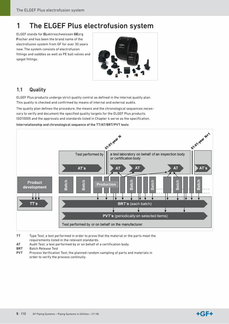
5 · 110 GF Piping Systems – Piping Systems in Utilities – (11.18)
The ELGEF Plus electrofusion system
1 The ELGEF Plus electrofusion systemELGEF stands for ELektroschweissen GEorg
Fischer and has been the brand name of the
electrofusionsystemfromGFforover30years
now. The system consists of electrofusion
fittingsandsaddlesaswellasPEballvalvesand
spigotfittings.
1.1 QualityELGEFPlusproductsundergostrictqualitycontrolasdefinedintheinternalqualityplan.
Thisqualityischeckedandconfirmedbymeansofinternalandexternalaudits.
Thequalityplandefinestheprocedure,themeansandthechronologicalsequencesneces-
sarytoverifyanddocumentthespecifiedqualitytargetsfortheELGEFPlusproducts.
ISO10005andtheapprovalsandstandardslistedinChapter4serveasthespecification.
Interrelationship and chronological sequence of the TT/AT/BRT/PVT tests
TT Type Test; a test performed in order to prove that the material or the parts meet the requirements listed in the relevant standards.
AT AuditTest;atestperformedbyoronbehalfofacertificationbody.BRT Batch Release TestPVT ProcessVerificationTest;theplannedrandomsamplingofpartsandmaterialsin
order to verify the process continuity.
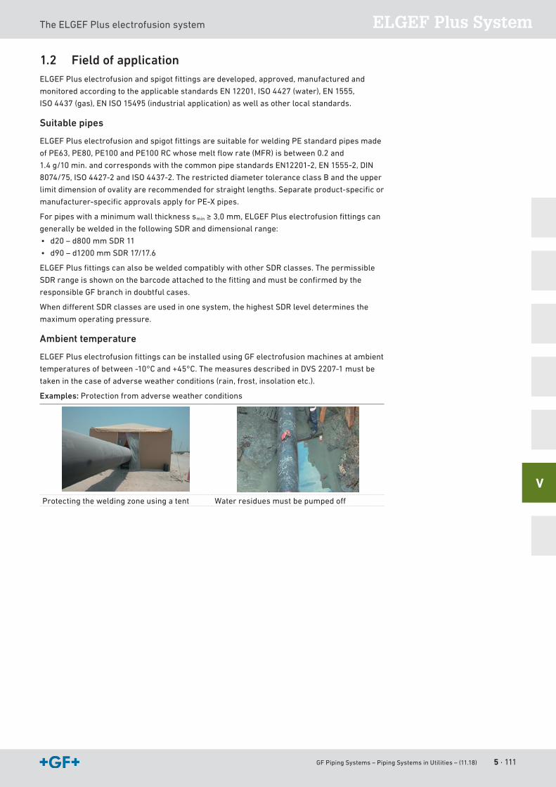
GF Piping Systems – Piping Systems in Utilities – (11.18) 5 · 111
ELGEF Plus SystemThe ELGEF Plus electrofusion system
V
1.2 Field of applicationELGEFPluselectrofusionandspigotfittingsaredeveloped,approved,manufacturedand
monitoredaccordingtotheapplicablestandardsEN12201,ISO4427(water),EN1555,
ISO4437(gas),ENISO15495(industrialapplication)aswellasotherlocalstandards.
Suitable pipes
ELGEFPluselectrofusionandspigotfittingsaresuitableforweldingPEstandardpipesmade
ofPE63,PE80,PE100andPE100RCwhosemeltflowrate(MFR)isbetween0.2and
1.4 g/10 min.andcorrespondswiththecommonpipestandardsEN12201-2,EN1555-2,DIN
8074/75,ISO4427-2andISO4437-2.TherestricteddiametertoleranceclassBandtheupper
limitdimensionofovalityarerecommendedforstraightlengths.Separateproduct-specificor
manufacturer-specificapprovalsapplyforPE-Xpipes.
For pipes with a minimum wall thickness smin≥3,0mm,ELGEFPluselectrofusionfittingscan
generally be welded in the following SDR and dimensional range:
• d20–d800mmSDR11
• d90–d1200mmSDR17/17.6
ELGEFPlusfittingscanalsobeweldedcompatiblywithotherSDRclasses.Thepermissible
SDRrangeisshownonthebarcodeattachedtothefittingandmustbeconfirmedbythe
responsible GF branch in doubtful cases.
WhendifferentSDRclassesareusedinonesystem,thehighestSDRleveldeterminesthe
maximum operating pressure.
Ambient temperature
ELGEFPluselectrofusionfittingscanbeinstalledusingGFelectrofusionmachinesatambient
temperaturesofbetween-10°Cand+45°C.ThemeasuresdescribedinDVS2207-1mustbe
takeninthecaseofadverseweatherconditions(rain,frost,insolationetc.).
Examples: Protection from adverse weather conditions
Protecting the welding zone using a tent Waterresiduesmustbepumpedoff
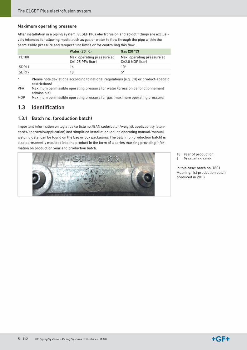
5 · 112 GF Piping Systems – Piping Systems in Utilities – (11.18)
The ELGEF Plus electrofusion system
Maximum operating pressure
Afterinstallationinapipingsystem,ELGEFPluselectrofusionandspigotfittingsareexclusi-
velyintendedforallowingmediasuchasgasorwatertoflowthroughthepipewithinthe
permissiblepressureandtemperaturelimitsorforcontrollingthisflow.
Water (20 °C) Gas (20 °C)
PE100 Max.operatingpressureatC=1.25 PFA [bar]
Max.operatingpressureatC=2.0MOP[bar]
SDR11 16 10*
SDR17 10 5*
* Pleasenotedeviationsaccordingtonationalregulations(e.g.CH)orproduct-specificrestrictions!
PFA Maximumpermissibleoperatingpressureforwater(pressiondefonctionnementadmissible)
MOP Maximumpermissibleoperatingpressureforgas(maximumoperatingpressure)
1.3 Identification
1.3.1 Batch no. (production batch)
Importantinformationonlogistics(articleno./EANcode/batch/weight),applicability(stan-
dards/approvals/application)andsimplifiedinstallation(onlineoperatingmanual/manual
welding data) can be found on the bag or box packaging. The batch no. (production batch) is
also permanently moulded into the product in the form of a series marking providing infor-
mation on production year and production batch.
18 Year of production1 Production batch
Inthiscase:batchno.1801 Meaning:1stproductionbatchproducedin2018
GF Piping Systems – Piping Systems in Utilities – (11.18) 5 · 113
ELGEF Plus SystemThe ELGEF Plus electrofusion system
V
1.3.2 Welding data and traceability
Welding data
Therearevariousdifferentwaysoftransmittingtheweldingdatatotheweldingunit.The
most widespread (and recommended) method is by reading in a welding barcode. The
contentsofthisweldingbarcodearedescribedinthestandardISO13950.Inputerrorsare
avoided by reading in the welding barcode. The welding parameters are automatically
transmitted to the welding unit.
Ifitisnotpossibletoreadintheweldingdataautomaticallybymeansoftheweldingbarcode,
the welding data can be entered manually.
Temperature-compensated welding times
AllELGEFPluselectrofusionfittingshaveabarcodewhichautomaticallyadaptsthewelding
timetotheambienttemperatureoftheweldingunit.Electrofusionfitting,pipeandwelding
unit have to be on the same temperature level before welding begins. Please note the time
necessary for adapting the temperature!
Traceability
Continuoustraceabilitysafeguardstheoperationofthepipingsystem.Foreachcomponent,
the entire processing chain can be traced back to the production of the raw materials.
ThesystemoftraceabilityisdescribedinthestandardISO12176,Part4.
Besidestheweldingbarcode,thestickerattachedtotheELGEFPluselectrofusionfittingalso
includes the traceability barcode. The information on the cooling time and the applicability of
thepermissibleSDRclassesofthepipecompletetheweldingdata.Inaddition,themanual
welding data in various temperature ranges is displayed on the bag label.
Documentation
The documentation of the work sequence for pipe installations is becoming more and more
important.Inthisconnection,theWeldinOnesoftwareassistsyouinweldingorsystem
maintenance. The Welding Book software extends the data about the joint beyond the welding
records gathered by the electrofusion and butt welding units. The software automatically
combines images made using any smartphone camera with the welding records in each case
in order to document all preparatory activities such as peeling and using clamp holders as
wellasusingthecorrectfittingsandpipes.TheBarcodeCreatorhelpsyoutocreatethe
OperatorIDsforyourfittersinaccordancewithyourcompetencesandtheISO12176-3
standard. It creates the order number in a transparent way in order to trace the installation or
the construction site and allows the automatic assignment of your joint to a certain code. The
Barcode Creator creates certain codes for the tools used at the construction site and even for
pipes(manufacturer,type,diameteranddateofpurchase).
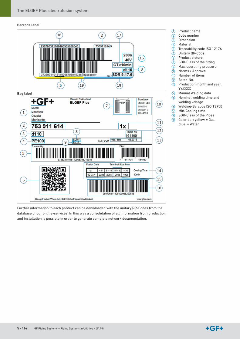
5 · 114 GF Piping Systems – Piping Systems in Utilities – (11.18)
The ELGEF Plus electrofusion system
Barcode label
Further information to each product can be downloaded with the unitary QR-Codes from the
database of our online-services. In this way a consolidation of all information from production
and installation is possible in order to generate complete network documentation.
a Product names Code numberd Dimensionf Materialg Traceability code ISO 12176h Unitary QR-Codej Product picturek SDR-Classofthefittingl Max.operatingpressure; Norms/ApprovalA Number of itemsS Batch-No.D Productionmonthandyear,
YY.XXXXF ManualWeldingdataG Nominal welding time and
welding voltageH Welding-BarcodeISO13950J Min.CoolingtimeK SDR-Class of the PipesL Colorbar:yellow=Gas,
blue = Water
Bag label
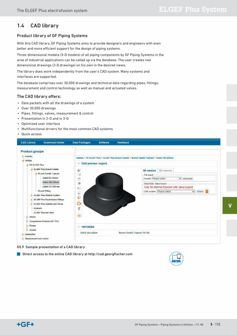
GF Piping Systems – Piping Systems in Utilities – (11.18) 5 · 115
ELGEF Plus SystemThe ELGEF Plus electrofusion system
V
1.4 CAD library
Product library of GF Piping Systems
WiththisCADlibrary,GFPipingSystemsaimstoprovidedesignersandengineerswitheven
betterandmoreefficientsupportforthedesignofpipingsystems.
Three-dimensional models (3-D models) of all piping components by GF Piping Systems in the
area of industrial applications can be called up via the database. The user creates two
dimensional drawings (2-D drawings) on his own in the desired views.
Thelibrarydoesworkindependentlyfromtheuser’sCADsystem.Manysystemsand
interfaces are supported.
Thedatabasecomprisesover30,000drawingsandtechnicaldataregardingpipes,fittings,
measurement and control technology as well as manual and actuated valves.
The CAD library offers:
• Data packets with all the drawings of a system
• Over30,000drawings
• Pipes,fittings,valves,measurement&control
• Presentation in 2-D and in 3-D
• Optimized user interface
• MultifunctionaldriversforthemostcommonCADsystems
• Quick access
G5.9 Sample presentation of a CAD library
Direct access to the online CAD library at http://cad.georgfischer.com
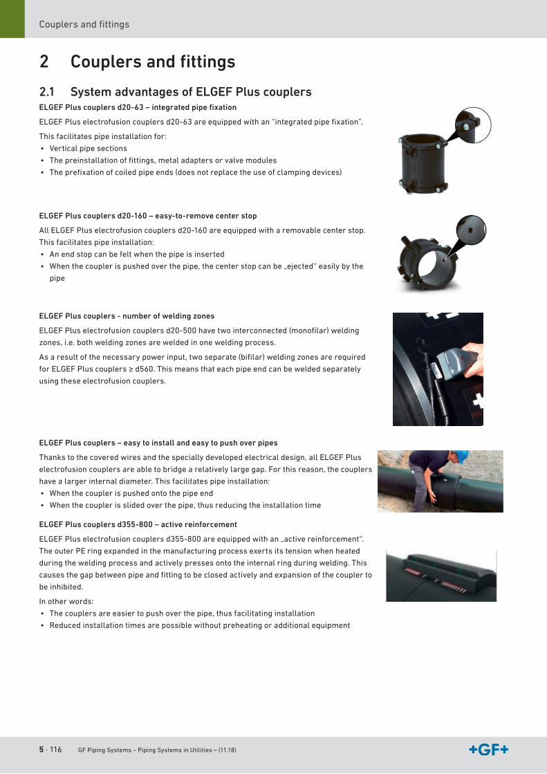
5 · 116 GF Piping Systems – Piping Systems in Utilities – (11.18)
Couplersandfittings
2 Couplers and fi ttings
2.1 System advantages of ELGEF Plus couplersELGEF Plus couplers d20-63 – integrated pipe fi xation
ELGEFPluselectrofusioncouplersd20-63areequippedwithan“integratedpipefixation”.
This facilitates pipe installation for:
• Vertical pipe sections
• Thepreinstallationoffittings,metaladaptersorvalvemodules
• Theprefixationofcoiledpipeends(doesnotreplacetheuseofclampingdevices)
ELGEF Plus couplers d20-160 – easy-to-remove center stop
AllELGEFPluselectrofusioncouplersd20-160areequippedwitharemovablecenterstop.
This facilitates pipe installation:
• An end stop can be felt when the pipe is inserted
• Whenthecouplerispushedoverthepipe,thecenterstopcanbe„ejected“easilybythe
pipe
ELGEF Plus couplers - number of welding zones
ELGEFPluselectrofusioncouplersd20-500havetwointerconnected(monofilar)welding
zones,i.e.bothweldingzonesareweldedinoneweldingprocess.
Asaresultofthenecessarypowerinput,twoseparate(bifilar)weldingzonesarerequired
forELGEFPluscouplers≥d560.Thismeansthateachpipeendcanbeweldedseparately
using these electrofusion couplers.
ELGEF Plus couplers – easy to install and easy to push over pipes
Thankstothecoveredwiresandthespeciallydevelopedelectricaldesign,allELGEFPlus
electrofusioncouplersareabletobridgearelativelylargegap.Forthisreason,thecouplers
have a larger internal diameter. This facilitates pipe installation:
• When the coupler is pushed onto the pipe end
• Whenthecouplerisslidedoverthepipe,thusreducingtheinstallationtime
ELGEF Plus couplers d355-800 – active reinforcement
ELGEFPluselectrofusioncouplersd355-800areequippedwithan„activereinforcement“.
The outer PE ring expanded in the manufacturing process exerts its tension when heated
during the welding process and actively presses onto the internal ring during welding. This
causesthegapbetweenpipeandfittingtobeclosedactivelyandexpansionofthecouplerto
be inhibited.
In other words:
• Thecouplersareeasiertopushoverthepipe,thusfacilitatinginstallation
• Reduced installation times are possible without preheating or additional equipment
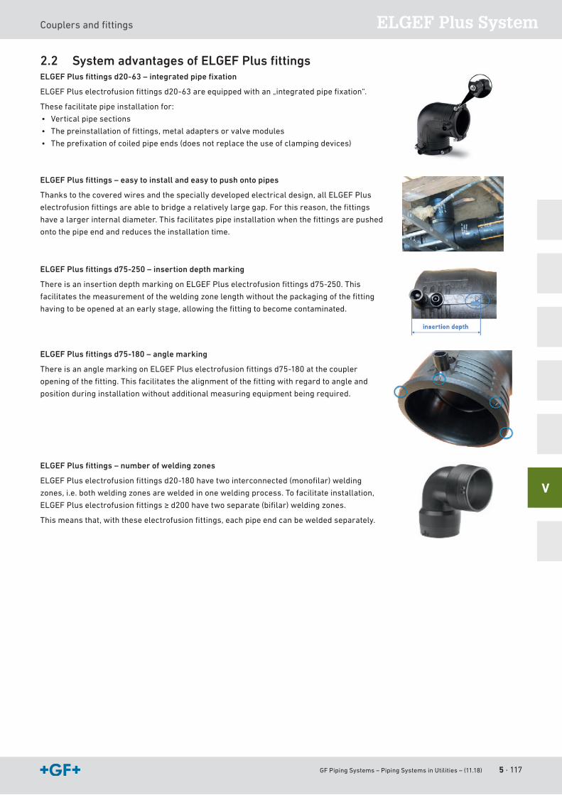
GF Piping Systems – Piping Systems in Utilities – (11.18) 5 · 117
ELGEF Plus SystemCouplersandfittings
V
2.2 System advantages of ELGEF Plus fi ttingsELGEF Plus fi ttings d20-63 – integrated pipe fi xation
ELGEFPluselectrofusionfittingsd20-63areequippedwithan„integratedpipefixation“.
These facilitate pipe installation for:
• Vertical pipe sections
• Thepreinstallationoffittings,metaladaptersorvalvemodules
• Theprefixationofcoiledpipeends(doesnotreplacetheuseofclampingdevices)
ELGEF Plus fi ttings – easy to install and easy to push onto pipes
Thankstothecoveredwiresandthespeciallydevelopedelectricaldesign,allELGEFPlus
electrofusionfittingsareabletobridgearelativelylargegap.Forthisreason,thefittings
havealargerinternaldiameter.Thisfacilitatespipeinstallationwhenthefittingsarepushed
onto the pipe end and reduces the installation time.
ELGEF Plus fi ttings d75-250 – insertion depth marking
ThereisaninsertiondepthmarkingonELGEFPluselectrofusionfittingsd75-250.This
facilitatesthemeasurementoftheweldingzonelengthwithoutthepackagingofthefitting
havingtobeopenedatanearlystage,allowingthefittingtobecomecontaminated.
ELGEF Plus fi ttings d75-180 – angle marking
ThereisananglemarkingonELGEFPluselectrofusionfittingsd75-180atthecoupler
openingofthefitting.Thisfacilitatesthealignmentofthefittingwithregardtoangleand
position during installation without additional measuring equipment being required.
ELGEF Plus fi ttings – number of welding zones
ELGEFPluselectrofusionfittingsd20-180havetwointerconnected(monofilar)welding
zones,i.e.bothweldingzonesareweldedinoneweldingprocess.Tofacilitateinstallation,
ELGEFPluselectrofusionfittings≥d200havetwoseparate(bifilar)weldingzones.
Thismeansthat,withtheseelectrofusionfittings,eachpipeendcanbeweldedseparately.
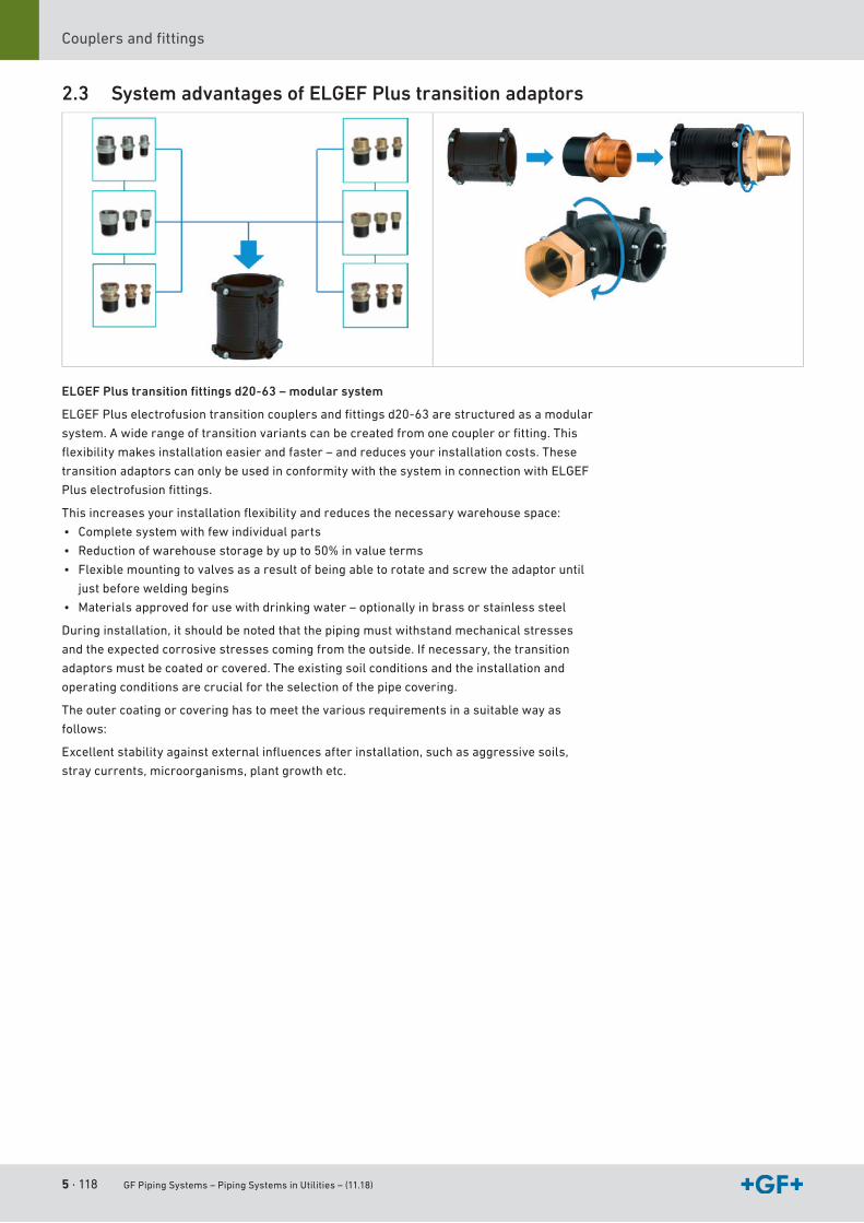
5 · 118 GF Piping Systems – Piping Systems in Utilities – (11.18)
Couplersandfittings
2.3 System advantages of ELGEF Plus transition adaptors
ELGEF Plus transition fi ttings d20-63 – modular system
ELGEFPluselectrofusiontransitioncouplersandfittingsd20-63arestructuredasamodular
system.Awiderangeoftransitionvariantscanbecreatedfromonecouplerorfitting.This
flexibilitymakesinstallationeasierandfaster–andreducesyourinstallationcosts.These
transition adaptors can only be used in conformity with the system in connection with ELGEF
Pluselectrofusionfittings.
Thisincreasesyourinstallationflexibilityandreducesthenecessarywarehousespace:
• Complete system with few individual parts
• Reductionofwarehousestoragebyupto50%invalueterms
• Flexible mounting to valves as a result of being able to rotate and screw the adaptor until
just before welding begins
• Materialsapprovedforusewithdrinkingwater–optionallyinbrassorstainlesssteel
Duringinstallation,itshouldbenotedthatthepipingmustwithstandmechanicalstresses
andtheexpectedcorrosivestressescomingfromtheoutside.Ifnecessary,thetransition
adaptors must be coated or covered. The existing soil conditions and the installation and
operating conditions are crucial for the selection of the pipe covering.
The outer coating or covering has to meet the various requirements in a suitable way as
follows:
Excellentstabilityagainstexternalinfluencesafterinstallation,suchasaggressivesoils,
straycurrents,microorganisms,plantgrowthetc.
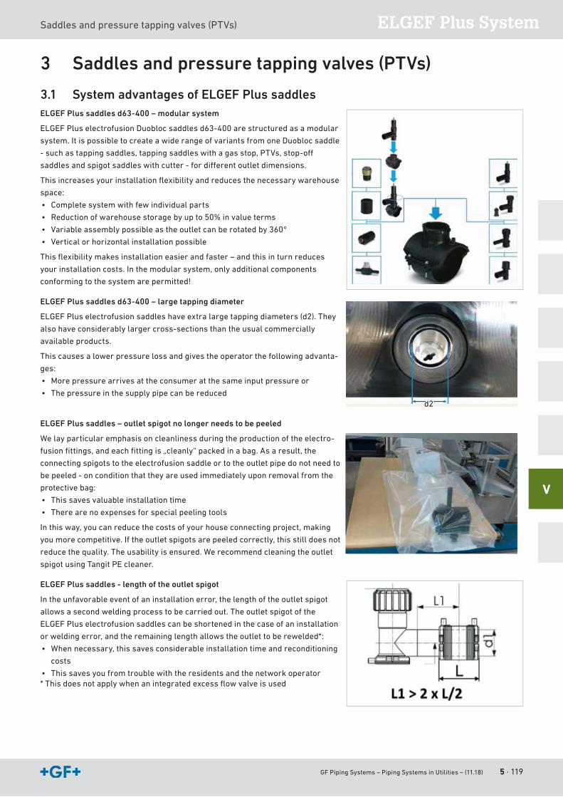
GF Piping Systems – Piping Systems in Utilities – (11.18) 5 · 119
ELGEF Plus SystemSaddles and pressure tapping valves (PTVs)
V
3 Saddles and pressure tapping valves (PTVs)
3.1 System advantages of ELGEF Plus saddlesELGEF Plus saddles d63-400 – modular system
ELGEFPluselectrofusionDuoblocsaddlesd63-400arestructuredasamodular
system. It is possible to create a wide range of variants from one Duobloc saddle
-suchastappingsaddles,tappingsaddleswithagasstop,PTVs,stop-off
saddlesandspigotsaddleswithcutter-fordifferentoutletdimensions.
Thisincreasesyourinstallationflexibilityandreducesthenecessarywarehouse
space:
• Complete system with few individual parts
• Reductionofwarehousestoragebyupto50%invalueterms
• Variableassemblypossibleastheoutletcanberotatedby360°
• Vertical or horizontal installation possible
Thisflexibilitymakesinstallationeasierandfaster–andthisinturnreduces
yourinstallationcosts.Inthemodularsystem,onlyadditionalcomponents
conforming to the system are permitted!
ELGEF Plus saddles d63-400 – large tapping diameter
ELGEF Plus electrofusion saddles have extra large tapping diameters (d2). They
also have considerably larger cross-sections than the usual commercially
available products.
This causes a lower pressure loss and gives the operator the following advanta-
ges:
• Morepressurearrivesattheconsumeratthesameinputpressureor
• The pressure in the supply pipe can be reduced
ELGEF Plus saddles – outlet spigot no longer needs to be peeled
We lay particular emphasis on cleanliness during the production of the electro-
fusionfittings,andeachfittingis„cleanly“packedinabag.Asaresult,the
connecting spigots to the electrofusion saddle or to the outlet pipe do not need to
be peeled - on condition that they are used immediately upon removal from the
protective bag:
• This saves valuable installation time
• There are no expenses for special peeling tools
Inthisway,youcanreducethecostsofyourhouseconnectingproject,making
youmorecompetitive.Iftheoutletspigotsarepeeledcorrectly,thisstilldoesnot
reduce the quality. The usability is ensured. We recommend cleaning the outlet
spigot using Tangit PE cleaner.
ELGEF Plus saddles - length of the outlet spigot
Intheunfavorableeventofaninstallationerror,thelengthoftheoutletspigot
allows a second welding process to be carried out. The outlet spigot of the
ELGEF Plus electrofusion saddles can be shortened in the case of an installation
orweldingerror,andtheremaininglengthallowstheoutlettoberewelded*:
• Whennecessary,thissavesconsiderableinstallationtimeandreconditioning
costs
• This saves you from trouble with the residents and the network operator*Thisdoesnotapplywhenanintegratedexcessflowvalveisused
d2
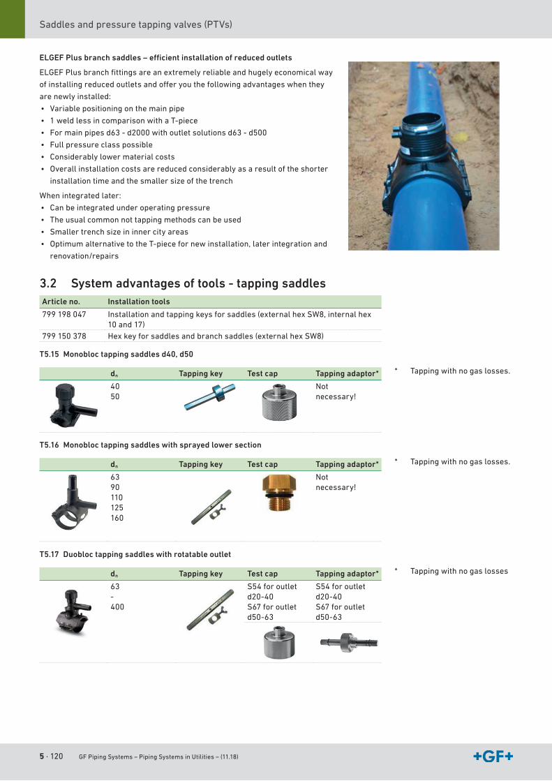
5 · 120 GF Piping Systems – Piping Systems in Utilities – (11.18)
Saddles and pressure tapping valves (PTVs)
ELGEF Plus branch saddles – effi cient installation of reduced outlets
ELGEFPlusbranchfittingsareanextremelyreliableandhugelyeconomicalway
ofinstallingreducedoutletsandofferyouthefollowingadvantageswhenthey
are newly installed:
• Variable positioning on the main pipe
• 1 weld less in comparison with a T-piece
• Formainpipesd63-d2000withoutletsolutionsd63-d500
• Full pressure class possible
• Considerably lower material costs
• Overall installation costs are reduced considerably as a result of the shorter
installation time and the smaller size of the trench
When integrated later:
• Can be integrated under operating pressure
• The usual common not tapping methods can be used
• Smaller trench size in inner city areas
• OptimumalternativetotheT-piecefornewinstallation,laterintegrationand
renovation/repairs
3.2 System advantages of tools - tapping saddlesArticle no. Installation tools
799198047 Installationandtappingkeysforsaddles(externalhexSW8,internalhex10and17)
799150378 Hexkeyforsaddlesandbranchsaddles(externalhexSW8)
T5.15 Monobloc tapping saddles d40, d50
dn Tapping key Test cap Tapping adaptor*
4050
Notnecessary!
T5.16 Monobloc tapping saddles with sprayed lower section
dn Tapping key Test cap Tapping adaptor*
6390110125160
Notnecessary!
T5.17 Duobloc tapping saddles with rotatable outlet
dn Tapping key Test cap Tapping adaptor*
63-400
S54 for outletd20-40S67 for outletd50-63
S54 for outletd20-40S67 for outletd50-63
* Tappingwithnogaslosses.
* Tappingwithnogaslosses.
* Tappingwithnogaslosses
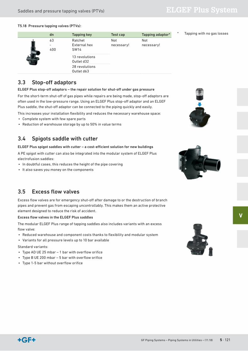
GF Piping Systems – Piping Systems in Utilities – (11.18) 5 · 121
ELGEF Plus SystemSaddles and pressure tapping valves (PTVs)
V
T5.18 Pressure tapping valves (PTVs):
dn Tapping key Test cap Tapping adaptor*
63-400
RatchetExternal hexSW14
Notnecessary!
Notnecessary!
13 revolutionsOutlet d3228 revolutionsOutlet d63
3.3 Stop-off adaptorsELGEF Plus stop-off adaptors – the repair solution for shut-off under gas pressure
Fortheshort-termshut-offofgaspipeswhilerepairsarebeingmade,stop-offadaptorsare
oftenusedinthelow-pressurerange.UsinganELGEFPlusstop-offadaptorandanELGEF
Plussaddle,theshut-offadaptorcanbeconnectedtothepipingquicklyandeasily.
Thisincreasesyourinstallationflexibilityandreducesthenecessarywarehousespace:
• Complete system with few spare parts
• Reductionofwarehousestoragebyupto50%invalueterms
3.4 Spigots saddle with cutterELGEF Plus spigot saddles with cutter – a cost-effi cient solution for new buildings
A PE spigot with cutter can also be integrated into the modular system of ELGEF Plus
electrofusion saddles:
• Indoubtfulcases,thisreducestheheightofthepipecovering
• It also saves you money on the components
3.5 Excess fl ow valvesExcessflowvalvesareforemergencyshut-offafterdamagetoorthedestructionofbranch
pipes and prevent gas from escaping uncontrollably. This makes them an active protective
element designed to reduce the risk of accident.
Excess fl ow valves in the ELGEF Plus saddles
The modular ELGEF Plus range of tapping saddles also includes variants with an excess
flowvalve:
• Reducedwarehouseandcomponentcoststhankstoflexibilityandmodularsystem
• Variantsforallpressurelevelsupto10baravailable
Standard variants:
• TypeADUE25mbar–1barwithoverfloworifice
• TypeBUE200mbar–5barwithoverfloworifice
• Type1-5barwithoutoverfloworifice
* Tappingwithnogaslosses
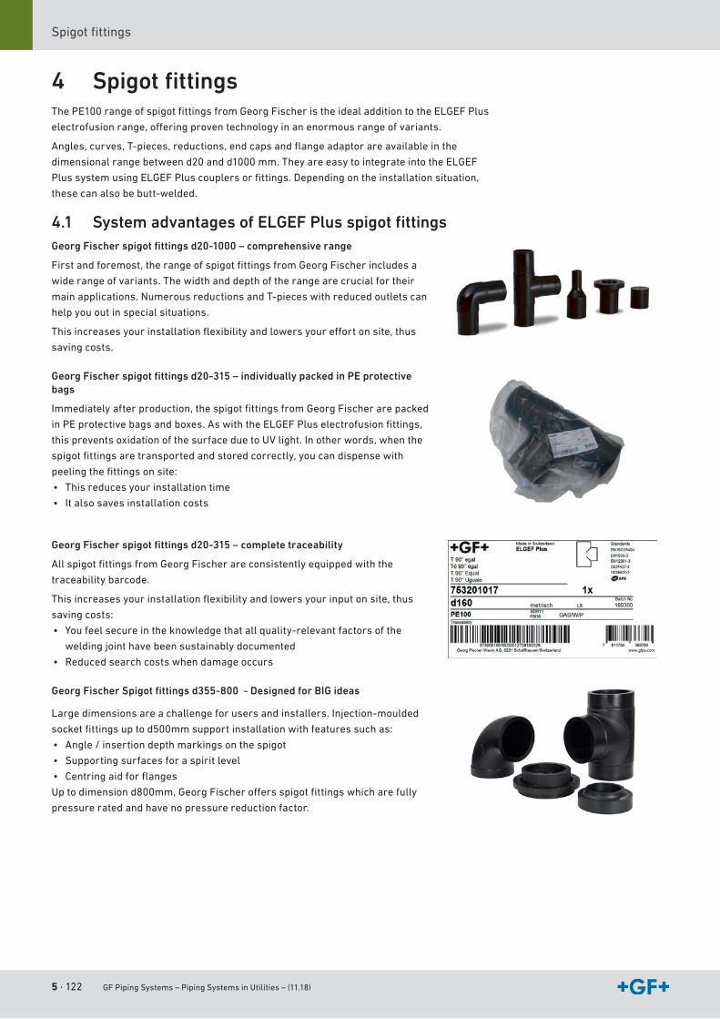
5 · 122 GF Piping Systems – Piping Systems in Utilities – (11.18)
Spigotfittings
4 Spigot fi ttingsThePE100rangeofspigotfittingsfromGeorgFischeristheidealadditiontotheELGEFPlus
electrofusionrange,offeringproventechnologyinanenormousrangeofvariants.
Angles,curves,T-pieces,reductions,endcapsandflangeadaptorareavailableinthe
dimensionalrangebetweend20andd1000mm.TheyareeasytointegrateintotheELGEF
PlussystemusingELGEFPluscouplersorfittings.Dependingontheinstallationsituation,
these can also be butt-welded.
4.1 System advantages of ELGEF Plus spigot fi ttingsGeorg Fischer spigot fi ttings d20-1000 – comprehensive range
Firstandforemost,therangeofspigotfittingsfromGeorgFischerincludesa
wide range of variants. The width and depth of the range are crucial for their
main applications. Numerous reductions and T-pieces with reduced outlets can
help you out in special situations.
Thisincreasesyourinstallationflexibilityandlowersyoureffortonsite,thus
saving costs.
Georg Fischer spigot fi ttings d20-315 – individually packed in PE protective bags
Immediatelyafterproduction,thespigotfittingsfromGeorgFischerarepacked
inPEprotectivebagsandboxes.AswiththeELGEFPluselectrofusionfittings,
thispreventsoxidationofthesurfaceduetoUVlight.Inotherwords,whenthe
spigotfittingsaretransportedandstoredcorrectly,youcandispensewith
peelingthefittingsonsite:
• This reduces your installation time
• It also saves installation costs
Georg Fischer spigot fi ttings d20-315 – complete traceability
AllspigotfittingsfromGeorgFischerareconsistentlyequippedwiththe
traceability barcode.
Thisincreasesyourinstallationflexibilityandlowersyourinputonsite,thus
saving costs:
• You feel secure in the knowledge that all quality-relevant factors of the
welding joint have been sustainably documented
• Reduced search costs when damage occurs
Georg Fischer Spigot fi ttings d355-800 - Designed for BIG ideas
Large dimensions are a challenge for users and installers. Injection-moulded
socketfittingsuptod500mmsupportinstallationwithfeaturessuchas:
• Angle/insertiondepthmarkingsonthespigot
• Supporting surfaces for a spirit level
• Centringaidforflanges
Uptodimensiond800mm,GeorgFischeroffersspigotfittingswhicharefully
pressure rated and have no pressure reduction factor.
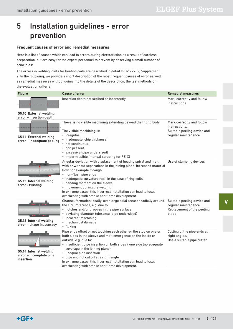
GF Piping Systems – Piping Systems in Utilities – (11.18) 5 · 123
ELGEF Plus SystemInstallation guidelines - error prevention
V
5 Installation guidelines - error prevention
Frequent causes of error and remedial measures
Hereisalistofcauseswhichcanleadtoerrorsduringelectrofusionasaresultofcareless
preparation,butareeasyfortheexpertpersonneltopreventbyobservingasmallnumberof
principles:
TheerrorsinweldingjointsforheatingcoilsaredescribedindetailInDVS2202,Supplement
2.Inthefollowing,weprovideashortdescriptionofthemostfrequentcausesoferroraswell
asremedialmeasureswithoutgoingintothedetailsofthedescription,thetestmethodsor
the evaluation criteria.
Figure Cause of error Remedial measures
G5.10 External welding error – insertion depth
Insertion depth not seribed or incorrectly Markcorrectlyandfollowinstructions
G5.11 External welding error – inadequate peeling
Thereisnovisiblemachiningextendingbeyondthefittingbody
The visible machining is:• irregular• inadequate (chip thickness)• not continuous• non present• excessive (pipe undersized)• impermissible(manualscrapingforPE-X)
Markcorrectlyandfollowinstructions.Suitable peeling device and regular maintenance
G5.12 Internal welding error - twisting
Angular deviation with displacement of heating spiral and melt withorwithoutseparationsinthejoiningplane,increasedmaterialflow,forexamplethrough• non-flushpipeends• inadequate curvature radii in the case of ring coils• bending moment on the sleeve• movement during the weldingInextremecases,thisincorrectinstallationcanleadtolocaloverheatingwithsmokeandflamedevelopment.
Use of clamping devices
G5.13 Internal welding error – shape inaccuracy
Channelformationlocally,overlargeaxialareasorradiallyaroundthecircumference,e.g.dueto:• notchesand/orgroovesinthepipesurface• deviating diameter tolerance (pipe undersized)• incorrect machining• mechanical damage• flaking
Suitable peeling device and regular maintenanceReplacement of the peeling blade
G5.14 Internal welding error – incomplete pipe insertion
Pipeendsoffsetornottouchingeachotherorthestopononeorboth sides in the sleeve and melt emergence on the inside or outside,e.g.dueto:• insufficientpipeinsertiononbothsides/oneside(noadequate
coverage in the joining plane)• unequal pipe insertion • pipeendnotcutoffatarightangleInextremecases,thisincorrectinstallationcanleadtolocaloverheatingwithsmokeandflamedevelopment.
Cutting of the pipe ends at right angles.Use a suitable pipe cutter
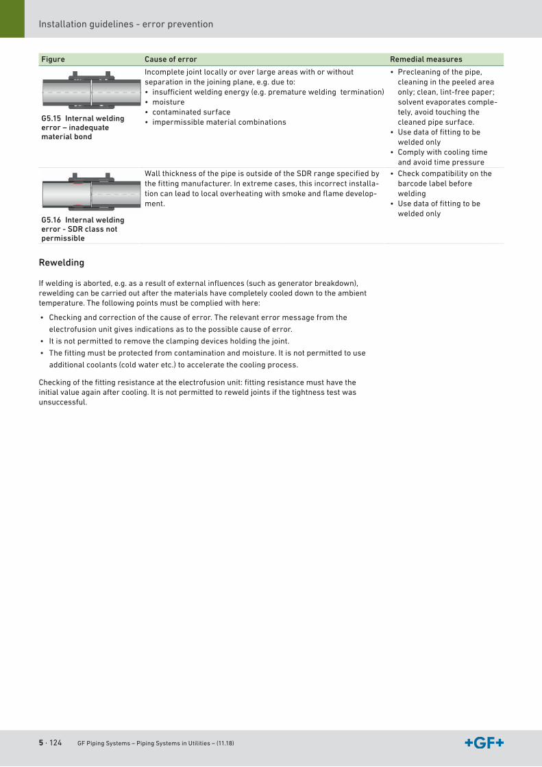
5 · 124 GF Piping Systems – Piping Systems in Utilities – (11.18)
Installation guidelines - error prevention
Figure Cause of error Remedial measures
G5.15 Internal welding error – inadequate material bond
Incomplete joint locally or over large areas with or without separationinthejoiningplane,e.g.dueto:• insufficientweldingenergy(e.g.prematureweldingtermination)• moisture• contaminated surface• impermissible material combinations
• Precleaningofthepipe,cleaning in the peeled area only;clean,lint-freepaper;solvent evaporates comple-tely,avoidtouchingthecleaned pipe surface.
• Usedataoffittingtobewelded only
• Comply with cooling time and avoid time pressure
G5.16 Internal welding error - SDR class not permissible
WallthicknessofthepipeisoutsideoftheSDRrangespecifiedbythefittingmanufacturer.Inextremecases,thisincorrectinstalla-tioncanleadtolocaloverheatingwithsmokeandflamedevelop-ment.
• Check compatibility on the barcode label before welding
• Usedataoffittingtobewelded only
Rewelding
Ifweldingisaborted,e.g.asaresultofexternalinfluences(suchasgeneratorbreakdown),rewelding can be carried out after the materials have completely cooled down to the ambient temperature. The following points must be complied with here:
• Checking and correction of the cause of error. The relevant error message from the
electrofusion unit gives indications as to the possible cause of error.
• It is not permitted to remove the clamping devices holding the joint.
• Thefittingmustbeprotectedfromcontaminationandmoisture.Itisnotpermittedtouse
additional coolants (cold water etc.) to accelerate the cooling process.
Checkingofthefittingresistanceattheelectrofusionunit:fittingresistancemusthavetheinitial value again after cooling. It is not permitted to reweld joints if the tightness test was unsuccessful.

GF Piping Systems – Piping Systems in Utilities – (11.18) 5 · 125
ELGEF Plus SystemElectrofusion units
V
6 Electrofusion units
6.1 Overview of electrofusion unitsMSA 125 MSA 230 MSA 330 MSA 2.0 MSA 340 MSA 2.1 MSA 2 MULTI MSA 4.0 MSA 4.1
Material PE/PP PE PE/PP PE/PP PE/PP PE/PP PE/PP/PB/PVDF
PE/PP PE/PP
Electrical data
Protection class IP54 IP54 IP54 IP65 IP54 IP65 IP65 IP65 IP65
Switch
Output voltage 8-42V 39-40V 8-48V 8-48V 8-48V 8-48V 3.6-40V 8-48V 8-48V
Output current max (A) 50 90 110 90 110 90 90 110 110
Display Graphical Alphanum Alphanum Graphical Alphanum Graphical Graphical Graphical Graphical
Data and operating control system
Protocols 350 350 500 350 1000 1000 500 5000 5000
Export protocols
Welding data format CSV/PDF CSV CSV/PDF CSV/PDF PDF/BIN PDF/BIN PDF/BIN PDF/BIN
Language variants 4 9 11 Symbols 11 Symbols Symbols 27 27
Mechanical data
Weight (kg) 13 19 23 11.9 23 11.9 11.9 12.5 12.5
Power cable length (m) 4 4 4 4 4 4 4 4 4
Welding cable length (m) 3 3 4 3 4 4 4 4 4
Functions
Order number
Manualweldingdatainput
Traceability
GPS
Workflowconfiguration
WeldinOne-compatible
QR code Optional
WLAN scanner
Online service apps
Mobilenetworkcomm.

5 · 126 GF Piping Systems – Piping Systems in Utilities – (11.18)
Electrofusion units
6.2 Demands on generators
Generators
Generators are used to ensure a reliable supply of electricity to the electrofusion unit at
construction sites. The following requirements must be taken into account here:
• Generatormaintainedregularly(onceyearlyaccordingtoDVS)withsufficientoutputpower
fortheelectrofusionunitandtheelectrofusionfittingstobewelded
• Sufficientfuelforthegeneratorforthetimeittakestomakethenecessarywelds
• The generator supplies the electrofusion unit only (no other consumers)
The generator provides the electrofusion unit with a safe and stable electrical network - even
under load - with the following basic conditions:
• Power output >3.5 kVA (or from d355 >6 kVA)
• Voltage230V±10%
• Frequency50Hertz±10%
• Current(back-upfuse)13to20A
6.2.1 Accessories
Adaptors
As the connectors on the cable of the electrofusion unit are subject to wear due to frequent
insertionandremoval,adaptorsshouldbeused.Thisreducesthecostsandprevents
unnecessary failure of the electrofusion unit. Worn-out adaptors must be replaced.
Angle adaptors
Someinstallationswhicharelocatedininner-cityareasorusemultifunctionalpipesoffer
verylittlespace.Inordertohavesufficientroomforthepowersupplyoftheelectrofusion
fittingwhileminimizinginstallationheight,itcanbehelpfultouseangleadaptors.
Extension cables
Maximum20mwithacross-sectionof2.5mm2.
6.2.2 Practical tips
Strain relief of welding cable
Intherestrictedspaceavailableinthetrench,youcouldtripovertheweldingcable.Ifthe
weldingcableisattachedbetweenelectrofusionunitandELGEFPlusfittingwithstrainrelief
(bywrappingthecableoncearoundthepipe),theweldingprocessisnotinterruptedinspite
of this occurrence.
Unwinding the cable roll
Asaresultoftheelectromagneticeffectofacoil,cabledrumsbetweengeneratorand
electrofusion unit must be unwound completely at all times.
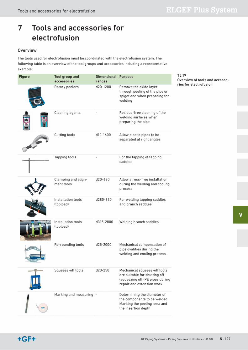
GF Piping Systems – Piping Systems in Utilities – (11.18) 5 · 127
ELGEF Plus SystemTools and accessories for electrofusion
V
7 Tools and accessories for electrofusion
Overview
The tools used for electrofusion must be coordinated with the electrofusion system. The
following table is an overview of the tool groups and accessories including a representative
example:
Figure Tool group and accessories
Dimensional ranges
Purpose
Rotary peelers d20-1200 Remove the oxide layer through peeling of the pipe or spigot end when preparing for welding
Cleaning agents - Residue-free cleaning of the welding surfaces when preparing the pipe
Cutting tools d10-1600 Allow plastic pipes to be separated at right angles
Tapping tools - For the tapping of tapping saddles
Clamping and align-ment tools
d20-630 Allow stress-free installation during the welding and cooling process
Installation tools (topload)
d280-630 For welding tapping saddles and branch saddles
Installation tools (topload)
d315-2000 Welding branch saddles
Re-rounding tools d25-2000 Mechanicalcompensationofpipe ovalities during the welding and cooling process
Squeeze-offtools d20-250 Mechanicalsqueeze-offtoolsaresuitableforshuttingoff(squeezingoff)PEpipesduringrepair and extension work.
Markingandmeasuring - Determining the diameter of the components to be welded.Markingthepeelingareaandthe insertion depth
T5.19 Overview of tools and accesso-ries for electrofusion

5 · 128 GF Piping Systems – Piping Systems in Utilities – (11.18)
Electrofusion units
GF Piping Systems – Piping Systems in Utilities – (11.18) A · 129
A
IndexAAbbreviations and units of measure 42Abrasion resistance PE 29Accredited test center 17Application solutions 21Approvals and Standards 33Automation 26
BBarcode and bag label 114Basic information about welding seam preparation 89Basic knowledge 41Batch-No. 112Blind flange 98Butt fusion jointing (heating element fusion conventional
butt fusion) 82
CCAD 115Calculation of allowable pressure/required wall thickness
53Chemical resistance 29Combustion behavior 29Control 26Conversion tables 45Couplers and fittings ELGEF Plus 116
DDesign and Laying 39Design factor 54
EElectrical properties PE 30Electrofusion (heating element fusion joints) 88Electrofusion units 125ELGEF Plus brackets and pressure tapping valves (PTVs)
119ELGEF Plus electrofusion unit 125ELGEF Plus Identification 112ELGEF Plus installation guidelines – error prevention 123ELGEF Plus range of application 111ELGEF Plus sockets 116ELGEF Plus spigot fittings 122ELGEF Plus System 109, 110Environment 19
FFlange connections 97Flow volume 45
GGaskets 104Gas Utilities 24GF Piping Systems 14
HHydraulic Calculation and Pressure Losses 65
IIdentification ELGEF Plus 112iJOINT 106Installation guidelines – error prevention ELGEF Plus
123Installation process 93Integral connections 82Internal pressure and leak test 78
JJointing Technology 82
LLaying 73Leak test 78Length of bolts 101Long-term behavior of PE 47Long-term behavior of thermoplastic materials 46Long-term behavior PE80 49Long-term behavior PE100 48
MMeasurement 26Mechanical joints 96Metric and British system of units 41MRS-values 46MULTI/JOINT 105
NNomogram 67
OOuter diameter 66Oxide layer 74
PPackaging concept 75Physiological properties PE 30Pipe diameters 65Pipelines under vacuum 59Pipe trenches 73Plastic piping materials 27Polyethylene (PE) 28Pressure and heads 45Pressure loss 70Pressure-temperature diagram for PE 50PRIMOFIT 107Processing and handling 74Product library 115Properties of Plastic Piping Materials 28
QQuality 17, 97
A · 130 GF Piping Systems – Piping Systems in Utilities – (11.18)
RRange of applications for pipes and fittings 50
SSaddles and pressure tapping valves (PTVs) ELGEF Plus
119Safety factors 57SDR 42Selecting plastic piping components 53SI-units 43Spigot fittings ELGEF Plus 122Standards and guidelines 34Storage 75Sustainability 19, 30
TThe ELGEF Plus electrofusion system 110Threaded fittings 97Tightening torque 100Tools for electrofusion 127Training 20Transition adapter with thread 97Transition fittings 118Transport 76Trenchless laying 74
UUNI-Coupling 108
VVacuum 59Viscosities 45
WWall thickness 53Water hammer 55Water Utilities 22Welding data and traceability 113

GF Piping Systems – Piping Systems in Utilities – (11.18) A · 131
A

A · 132 GF Piping Systems – Piping Systems in Utilities – (11.18)
700.671.677GFDO_P-UT_01_EN (12.18)© Georg Fischer Piping Systems Ltd. CH-8201 Scha� hausen/Switzerland, 2018
UtilityBuilding Technology
Industry
GF Piping Systems
The information and technical data (altogether “Data”) herein are not binding, unless explicitly confirmed in writing. The Data neither constitutes any expressed, implied or warranted characteristics, nor guaranteed properties or a guaranteed durability. All Data is subject to modification. The General Terms and Conditions of Sale of Georg Fischer Piping Systems apply.
Worldwide at homeOur sales companies and representatives ensure local customer support in more than 100 countries.
www.gfps.com
Argentina / Southern South AmericaGeorg Fischer Central Plastics Sudamérica S.R.L.Buenos Aires / ArgentinaPhone +54 11 4512 02 [email protected]/ar
AustraliaGeorge Fischer Pty LtdRiverwood NSW 2210Phone +61 (0) 2 9502 8000 [email protected]/au
AustriaGeorg Fischer Rohrleitungssysteme GmbH3130 HerzogenburgPhone +43 (0) 2782 856 [email protected]/at
Georg Fischer Fittings GmbH3160 TraisenPhone +43 (0) 2762 [email protected]
Belgium / LuxembourgGeorg Fischer NV/SA1600 Sint-Pieters-Leeuw / BelgiumPhone +32 (0) 2 556 40 20Fax +32 (0) 2 524 34 [email protected]/be
BrazilGeorg Fischer Sist. de Tub. Ltda.04571-020 São Paulo/SPPhone +55 (0) 11 5525 [email protected]/br
CanadaGeorg Fischer Piping Systems LtdMississauga, ON L5T 2B2Phone +1 (905) 670 8005Fax +1 (905) 670 [email protected]/ca
ChinaGeorg Fischer Piping Systems Ltd Shanghai 201319Phone +86 21 3899 3899 [email protected]/cn
Chinaust Plastics Corp. Ltd.Songlindian, Zhuozhou city, Hebei province, China, 072761Phone +86 312 395 2000Fax +86 312 365 [email protected]
Denmark / IcelandGeorg Fischer A/S2630 Taastrup / DenmarkPhone +45 (0) 70 22 19 [email protected]/dk
FinlandGeorg Fischer AB01510 VantaaPhone +358 (0) 9 586 58 25 Fax +358 (0) 9 586 58 [email protected]/fi
FranceGeorg Fischer SAS95932 Roissy Charles de Gaulle CedexPhone +33 (0) 1 41 84 68 [email protected]/fr
GermanyGeorg Fischer GmbH73095 Albershausen Phone +49 (0) 7161 302 [email protected]/de
IndiaGeorg Fischer Piping Systems Pvt. Ltd400 083 MumbaiPhone +91 22 4007 2000 Fax +91 22 4007 [email protected]/in
ItalyGeorg Fischer S.p.A.20063 Cernusco S/N (MI)Phone +39 02 921 [email protected]/it
Georg Fischer TPA S.r.l.IT-16012 Busalla (GE)Phone +39 010 962 47 [email protected]/it
JapanGeorg Fischer Ltd530-0003 Osaka Phone +81 (0) 6 6341 [email protected]/jp
KoreaGeorg Fischer Korea Co. LtdUnit 2501, U-Tower120 Heungdeok Jungang-ro (Yeongdeok-dong) Giheung-gu, Yongin-si, Gyeonggi-do Phone +82 31 8017 1450Fax +82 31 217 [email protected]/kr
MalaysiaGeorge Fischer (M) Sdn. Bhd.41200 Klang, Selangor Darul EhsanPhone +60 (0) 3 3122 5585Fax +60 (0) 3 3122 [email protected]/my
Mexico / Northern Latin AmericaGeorg Fischer S.A. de C.V.CP 66636 Apodaca, Nuevo Leon / MexicoPhone +52 (81) 1340 8586Fax +52 (81) 1522 [email protected]/mx
Middle EastGeorg Fischer Piping Systems (Switzerland) LtdDubai / United Arab EmiratesPhone +971 4 289 49 [email protected]/int
NetherlandsGeorg Fischer N.V.8161 PA EpePhone +31 (0) 578 678 222 [email protected]/nl
Georg Fischer Waga N.V.NL-8160 AG EpePhone +31 (0) 578 678 [email protected]
New ZealandGeorg Fischer Ltd5018 Upper HuttPhone +04 527 9813Fax +04 527 [email protected]/nz
NorwayGeorg Fischer AS1351 Rud Phone +47 67 18 29 [email protected]/no
PolandGeorg Fischer Sp. z o.o.05-090 Sekocin Nowy Phone +48 (0) 22 31 31 0 50 [email protected]/pl
RomaniaGeorg Fischer Piping Systems (Switzerland) Ltd020257 Bucharest - Sector 2Phone +40 (0) 21 230 53 [email protected]/int
RussiaGeorg Fischer Piping Systems (Switzerland) LtdMoscow 125040Phone +7 495 748 11 [email protected]/ru
SingaporeGeorge Fischer Pte Ltd528 872 SingaporePhone +65 6747 0611Fax +65 6747 [email protected]/sg
Spain / PortugalGeorg Fischer S.A.28046 Madrid / SpainPhone +34 (0) 91 781 98 [email protected]/es
SwedenGeorg Fischer AB117 43 StockholmPhone +46 (0) 8 506 775 [email protected]/se
SwitzerlandGeorg Fischer Rohrleitungssysteme (Schweiz) AG8201 SchaffhausenPhone +41 (0) 52 631 [email protected]/ch
TaiwanGeorg Fischer Co. LtdSan Chung Dist., New Taipei CityPhone +886 2 8512 2822Fax +886 2 8512 2823www.gfps.com/tw
United Kingdom / IrelandGeorge Fischer Sales LimitedCoventry, CV2 2ST / United KingdomPhone +44 (0) 2476 535 [email protected]/uk
USA / CaribbeanGeorg Fischer LLC92618 Irvine, CA / USAPhone +1 714 731 88 00 Fax +1 714 731 62 [email protected]/us
Georg Fischer Central Plastics LLCShawnee, OK 74801 / USAPhone +1 (405) 273 63 [email protected]
VietnamGeorge Fischer Pte LtdRepresentative OfficeHo Chi Minh CityPhone + 84 28 3948 4000Fax + 84 28 3948 [email protected]/vn
International Georg Fischer Piping Systems (Switzerland) Ltd8201 Schaffhausen / SwitzerlandPhone +41 (0) 52 631 3003Fax +41 (0) 52 631 [email protected]/int
170106-backcover-A4-utility_blue.indd 1 11.09.2018 11:08:40
Price 45 CHF
Pla
n, B
uild
, Ope
rate
Uti
lity