refrigeration piping and heat transfer components
TRANSCRIPT
Refrigeration Piping andHeat Transfer ComponentsASME Code for Pressure Piping, B31
A N A M E R I C A N N A T I O N A L S T A N D A R D
ASME B31.5-2016(Revision of ASME B31.5-2013)
ASME B31.5-2016(Revision of ASME B31.5-2013)
RefrigerationPiping andHeat TransferComponentsASME Code for Pressure Piping, B31
A N A M E R I C A N N A T I O N A L S T A N D A R D
Two Park Avenue • New York, NY • 10016 USA
Date of Issuance: June 29, 2016
The next edition of this Code is scheduled for publication in 2019. This Code will become effective6 months after the Date of Issuance.
ASME issues written replies to inquiries concerning interpretations of technical aspects of this Code.Interpretations are published under http://go.asme.org/Interpretations. Periodically certain actionsof the ASME B31 Committees may be published as Cases. Cases are published on the ASME Website under the Committee Pages at http://go.asme.org/B31committee as they are issued.
Errata to codes and standards may be posted on the ASME Web site under the Committee Pages ofthe associated codes and standards to provide corrections to incorrectly published items, or to correcttypographical or grammatical errors in codes and standards. Such errata shall be used on the dateposted.
The B31 Committee Pages can be found at http://go.asme.org/B31committee. The associated B31Committee Pages for each code and standard can be accessed from this main page. There is anoption available to automatically receive an e-mail notification when errata are posted to a particularcode or standard. This option can be found on the appropriate Committee Page after selecting “Errata”in the “Publication Information” section.
ASME is the registered trademark of The American Society of Mechanical Engineers.
This code or standard was developed under procedures accredited as meeting the criteria for American NationalStandards. The Standards Committee that approved the code or standard was balanced to assure that individuals fromcompetent and concerned interests have had an opportunity to participate. The proposed code or standard was madeavailable for public review and comment that provides an opportunity for additional public input from industry, academia,regulatory agencies, and the public-at-large.
ASME does not “approve,” “rate,” or “endorse” any item, construction, proprietary device, or activity.ASME does not take any position with respect to the validity of any patent rights asserted in connection with any
items mentioned in this document, and does not undertake to insure anyone utilizing a standard against liability forinfringement of any applicable letters patent, nor assumes any such liability. Users of a code or standard are expresslyadvised that determination of the validity of any such patent rights, and the risk of infringement of such rights, isentirely their own responsibility.
Participation by federal agency representative(s) or person(s) affiliated with industry is not to be interpreted asgovernment or industry endorsement of this code or standard.
ASME accepts responsibility for only those interpretations of this document issued in accordance with the establishedASME procedures and policies, which precludes the issuance of interpretations by individuals.
No part of this document may be reproduced in any form,in an electronic retrieval system or otherwise,
without the prior written permission of the publisher.
The American Society of Mechanical EngineersTwo Park Avenue, New York, NY 10016-5990
Copyright © 2016 byTHE AMERICAN SOCIETY OF MECHANICAL ENGINEERS
All rights reservedPrinted in U.S.A.
CONTENTS
Foreword . . . . . . . . . . . . . . . . . . . . . . . . . . . . . . . . . . . . . . . . . . . . . . . . . . . . . . . . . . . . . . . . . . . . . . . . . . . . . . vCommittee Roster . . . . . . . . . . . . . . . . . . . . . . . . . . . . . . . . . . . . . . . . . . . . . . . . . . . . . . . . . . . . . . . . . . . . . viIntroduction . . . . . . . . . . . . . . . . . . . . . . . . . . . . . . . . . . . . . . . . . . . . . . . . . . . . . . . . . . . . . . . . . . . . . . . . . . . viiiSummary of Changes . . . . . . . . . . . . . . . . . . . . . . . . . . . . . . . . . . . . . . . . . . . . . . . . . . . . . . . . . . . . . . . . . . x
Chapter I Scope and Definitions . . . . . . . . . . . . . . . . . . . . . . . . . . . . . . . . . . . . . . . . . . . . . . . . . . . . . . 1500 General Statements . . . . . . . . . . . . . . . . . . . . . . . . . . . . . . . . . . . . . . . . . . . . . . . . . . . . . . . . 1
Chapter II Design . . . . . . . . . . . . . . . . . . . . . . . . . . . . . . . . . . . . . . . . . . . . . . . . . . . . . . . . . . . . . . . . . . . . . 8Part 1 Conditions and Criteria . . . . . . . . . . . . . . . . . . . . . . . . . . . . . . . . . . . . . . . . . . . . . . . . . . . . . 8501 Design Conditions . . . . . . . . . . . . . . . . . . . . . . . . . . . . . . . . . . . . . . . . . . . . . . . . . . . . . . . . 8502 Design Criteria . . . . . . . . . . . . . . . . . . . . . . . . . . . . . . . . . . . . . . . . . . . . . . . . . . . . . . . . . . . . 9Part 2 Design of Piping Components . . . . . . . . . . . . . . . . . . . . . . . . . . . . . . . . . . . . . . . . . . . . . . 24503 Criteria for Design of Piping Components . . . . . . . . . . . . . . . . . . . . . . . . . . . . . . . . . 24504 Pressure Design of Piping Components . . . . . . . . . . . . . . . . . . . . . . . . . . . . . . . . . . . . 24Part 3 Design Application of Piping Components Selection and Limitations . . . . . . . . . . 33505 Pipe . . . . . . . . . . . . . . . . . . . . . . . . . . . . . . . . . . . . . . . . . . . . . . . . . . . . . . . . . . . . . . . . . . . . . . 33506 Fittings, Bends, and Intersections . . . . . . . . . . . . . . . . . . . . . . . . . . . . . . . . . . . . . . . . . . 34507 Valves . . . . . . . . . . . . . . . . . . . . . . . . . . . . . . . . . . . . . . . . . . . . . . . . . . . . . . . . . . . . . . . . . . . . 34508 Flanges, Blanks, Flange Facings, Gaskets, and Bolting . . . . . . . . . . . . . . . . . . . . . . 35Part 4 Selection and Limitations of Piping Joints . . . . . . . . . . . . . . . . . . . . . . . . . . . . . . . . . . . 35510 Piping Joints . . . . . . . . . . . . . . . . . . . . . . . . . . . . . . . . . . . . . . . . . . . . . . . . . . . . . . . . . . . . . . 35511 Welded Joints . . . . . . . . . . . . . . . . . . . . . . . . . . . . . . . . . . . . . . . . . . . . . . . . . . . . . . . . . . . . . 35512 Flanged Joints . . . . . . . . . . . . . . . . . . . . . . . . . . . . . . . . . . . . . . . . . . . . . . . . . . . . . . . . . . . . . 36513 Expanded Joints . . . . . . . . . . . . . . . . . . . . . . . . . . . . . . . . . . . . . . . . . . . . . . . . . . . . . . . . . . 36514 Threaded Joints . . . . . . . . . . . . . . . . . . . . . . . . . . . . . . . . . . . . . . . . . . . . . . . . . . . . . . . . . . . 36515 Flared, Flareless, and Compression Joints . . . . . . . . . . . . . . . . . . . . . . . . . . . . . . . . . . 36517 Brazed and Soldered Joints . . . . . . . . . . . . . . . . . . . . . . . . . . . . . . . . . . . . . . . . . . . . . . . . 37518 Sleeve Coupled and Other Novel or Patented Joints . . . . . . . . . . . . . . . . . . . . . . . . 37Part 5 Expansion, Flexibility, Structural Attachments, Supports, and Restraints . . . . . . 37519 Expansion and Flexibility . . . . . . . . . . . . . . . . . . . . . . . . . . . . . . . . . . . . . . . . . . . . . . . . . . 37520 Design of Pipe Supporting Elements . . . . . . . . . . . . . . . . . . . . . . . . . . . . . . . . . . . . . . . 46521 Design Loads for Pipe Supporting Elements . . . . . . . . . . . . . . . . . . . . . . . . . . . . . . . 47
Chapter III Materials . . . . . . . . . . . . . . . . . . . . . . . . . . . . . . . . . . . . . . . . . . . . . . . . . . . . . . . . . . . . . . . . . . 49523 Materials — General Requirements . . . . . . . . . . . . . . . . . . . . . . . . . . . . . . . . . . . . . . . . 49524 Materials Applied to Miscellaneous Parts . . . . . . . . . . . . . . . . . . . . . . . . . . . . . . . . . . 55
Chapter IV Dimensional Requirements . . . . . . . . . . . . . . . . . . . . . . . . . . . . . . . . . . . . . . . . . . . . . . . . . . 56526 Dimensional Requirements for Standard and Nonstandard Piping
Components . . . . . . . . . . . . . . . . . . . . . . . . . . . . . . . . . . . . . . . . . . . . . . . . . . . . . . . . . . . . 56
Chapter V Fabrication and Assembly . . . . . . . . . . . . . . . . . . . . . . . . . . . . . . . . . . . . . . . . . . . . . . . . . . . 58527 Welding . . . . . . . . . . . . . . . . . . . . . . . . . . . . . . . . . . . . . . . . . . . . . . . . . . . . . . . . . . . . . . . . . . 58528 Brazing and Soldering . . . . . . . . . . . . . . . . . . . . . . . . . . . . . . . . . . . . . . . . . . . . . . . . . . . . . 67529 Bending — Hot and Cold . . . . . . . . . . . . . . . . . . . . . . . . . . . . . . . . . . . . . . . . . . . . . . . . . . 68530 Forming . . . . . . . . . . . . . . . . . . . . . . . . . . . . . . . . . . . . . . . . . . . . . . . . . . . . . . . . . . . . . . . . . . 68531 Heat Treatment . . . . . . . . . . . . . . . . . . . . . . . . . . . . . . . . . . . . . . . . . . . . . . . . . . . . . . . . . . . 68535 Assembly . . . . . . . . . . . . . . . . . . . . . . . . . . . . . . . . . . . . . . . . . . . . . . . . . . . . . . . . . . . . . . . . . 69
iii
Chapter VI Examination, Inspection, and Testing . . . . . . . . . . . . . . . . . . . . . . . . . . . . . . . . . . . . . . . . 73536 Examination . . . . . . . . . . . . . . . . . . . . . . . . . . . . . . . . . . . . . . . . . . . . . . . . . . . . . . . . . . . . . . 73537 Inspection . . . . . . . . . . . . . . . . . . . . . . . . . . . . . . . . . . . . . . . . . . . . . . . . . . . . . . . . . . . . . . . . 75538 Testing . . . . . . . . . . . . . . . . . . . . . . . . . . . . . . . . . . . . . . . . . . . . . . . . . . . . . . . . . . . . . . . . . . . 75539 Records . . . . . . . . . . . . . . . . . . . . . . . . . . . . . . . . . . . . . . . . . . . . . . . . . . . . . . . . . . . . . . . . . . . 76
Figures502.3.2 Stress Range Reduction Factors . . . . . . . . . . . . . . . . . . . . . . . . . . . . . . . . . . . . . . . . . . . . 23504.3.1-1 Reinforcement of Branch Connections . . . . . . . . . . . . . . . . . . . . . . . . . . . . . . . . . . . . . . 27504.3.1-2 Extruded Outlet Header Notation . . . . . . . . . . . . . . . . . . . . . . . . . . . . . . . . . . . . . . . . . 29504.3.1-3 Mechanically Formed Tee Connections in Copper Materials . . . . . . . . . . . . . . . . 31504.5.3 Blanks . . . . . . . . . . . . . . . . . . . . . . . . . . . . . . . . . . . . . . . . . . . . . . . . . . . . . . . . . . . . . . . . . . . . 34519.4.5-1 Bends . . . . . . . . . . . . . . . . . . . . . . . . . . . . . . . . . . . . . . . . . . . . . . . . . . . . . . . . . . . . . . . . . . . . . 44519.4.5-2 Branch Connections . . . . . . . . . . . . . . . . . . . . . . . . . . . . . . . . . . . . . . . . . . . . . . . . . . . . . . . 45523.2.2 Reduction in Minimum Design Metal Temperature Without Impact
Testing . . . . . . . . . . . . . . . . . . . . . . . . . . . . . . . . . . . . . . . . . . . . . . . . . . . . . . . . . . . . . . . . . 53527.1.2 Typical Joints With Backing Ring . . . . . . . . . . . . . . . . . . . . . . . . . . . . . . . . . . . . . . . . . . 59527.2.1-1 Butt Welding End Preparation . . . . . . . . . . . . . . . . . . . . . . . . . . . . . . . . . . . . . . . . . . . . . 59527.2.1-2 Internal Trimming for Butt Welding of Piping Components With Internal
Misalignment . . . . . . . . . . . . . . . . . . . . . . . . . . . . . . . . . . . . . . . . . . . . . . . . . . . . . . . . . . . 59527.3.3-1 Fillet Weld Size . . . . . . . . . . . . . . . . . . . . . . . . . . . . . . . . . . . . . . . . . . . . . . . . . . . . . . . . . . . 60527.3.3-2 Welding Details for Slip-On and Socket Welding Flanges, and Some
Acceptable Types of Flange Attachment Welds . . . . . . . . . . . . . . . . . . . . . . . . . . . 61527.3.3-3 Minimum Welding Dimensions Required for Socket Welding
Components Other Than Flanges . . . . . . . . . . . . . . . . . . . . . . . . . . . . . . . . . . . . . . . . 61527.3.5-1 Typical Welded Branch Connection Without Additional Reinforcement . . . . . 62527.3.5-2 Typical Welded Branch Connection With Additional Reinforcement . . . . . . . . . 62527.3.5-3 Typical Welded Angular Branch Connection Without Additional
Reinforcement . . . . . . . . . . . . . . . . . . . . . . . . . . . . . . . . . . . . . . . . . . . . . . . . . . . . . . . . . . 62527.3.5-4 Some Acceptable Types of Welded Branch Attachment Details Showing
Minimum Acceptable Welds . . . . . . . . . . . . . . . . . . . . . . . . . . . . . . . . . . . . . . . . . . . . 63527.3.5-5 Some Acceptable Details for Integrally Reinforced Outlet Fittings . . . . . . . . . . . 64527.3.6-1 Acceptable Welds for Flat Plate Closures . . . . . . . . . . . . . . . . . . . . . . . . . . . . . . . . . . . 66527.3.6-2 Unacceptable Welds for Flat Plate Closures . . . . . . . . . . . . . . . . . . . . . . . . . . . . . . . . 67
Tables500.2-1 Refrigerant Safety Classifications . . . . . . . . . . . . . . . . . . . . . . . . . . . . . . . . . . . . . . . . . . 4500.2-2 Safety Classifications for Refrigerant Blends . . . . . . . . . . . . . . . . . . . . . . . . . . . . . . . . 6502.3.1 Maximum Allowable Stress Values, ksi . . . . . . . . . . . . . . . . . . . . . . . . . . . . . . . . . . . . 10514 Minimum Thickness of External Threaded Components . . . . . . . . . . . . . . . . . . . . 36519.3.1 Thermal Expansion Data, e (IP and SI) . . . . . . . . . . . . . . . . . . . . . . . . . . . . . . . . . . . . . 39519.3.2 Moduli of Elasticity, E (IP and SI) . . . . . . . . . . . . . . . . . . . . . . . . . . . . . . . . . . . . . . . . . . 40519.3.6 Flexibility Factor, k, and Stress Intensification Factor, i . . . . . . . . . . . . . . . . . . . . . . 41521.3.1 Minimum Sizes of Straps, Rods, and Chains for Hangers . . . . . . . . . . . . . . . . . . . 48523.1 Acceptable Materials — Specifications . . . . . . . . . . . . . . . . . . . . . . . . . . . . . . . . . . . . . 50523.2.2 Impact Exemption Temperatures . . . . . . . . . . . . . . . . . . . . . . . . . . . . . . . . . . . . . . . . . . . 54526.1 Dimensional Standards . . . . . . . . . . . . . . . . . . . . . . . . . . . . . . . . . . . . . . . . . . . . . . . . . . . . 57531.2.1 Heat Treatment of Welds . . . . . . . . . . . . . . . . . . . . . . . . . . . . . . . . . . . . . . . . . . . . . . . . . . 70
Nonmandatory AppendicesA Referenced Standards . . . . . . . . . . . . . . . . . . . . . . . . . . . . . . . . . . . . . . . . . . . . . . . . . . . . . 77B Preparation of Technical Inquiries . . . . . . . . . . . . . . . . . . . . . . . . . . . . . . . . . . . . . . . . . 80C Selecting Applicable Piping Codes . . . . . . . . . . . . . . . . . . . . . . . . . . . . . . . . . . . . . . . . . 81D Nomenclature . . . . . . . . . . . . . . . . . . . . . . . . . . . . . . . . . . . . . . . . . . . . . . . . . . . . . . . . . . . . . 83
iv
FOREWORD
The need for a national code for pressure pipingbecame increasingly evident from 1915 to 1925. To meetthis need, the American Engineering StandardsCommittee (later changed to American StandardsAssociation, then changed to United States of AmericaStandards Institute, and now known as the AmericanNational Standards Institute) initiated project B31 inMarch 1926, at the request of The American Society ofMechanical Engineers and with that Society the soleadministrative sponsor. Because of the wide fieldinvolved, Sectional Committee B31, later changed toStandards Committee, was composed of representativesof some 40 different engineering societies, industries,government bureaus, institutes, and trade associations.After several years’ work, the first edition was publishedin 1935 as an American Tentative Standard Code forPressure Piping.
In order to keep the Code abreast of current develop-ments in piping design, welding, stress computations,new dimensional and material standards and specifica-tions, and increases in the severity of service conditions,revisions, supplements, and new editions of the Codewere published as follows:
B31.1-1942 American Standard Code for PressurePiping
B31.1a-1944 Supplement 1B31.1b-1947 Supplement 2B31.1-1951 American Standard Code for Pressure
PipingB31.1a-1953 Supplement 1 to B31.1-1951
v
B31.1-1955 American Standard Code for PressurePiping
In 1952, a new section of the Code was published tocover Gas Transmission and Distribution PipingSystems. In 1955, after a review by B31 Executive andSectional Committees, a decision was made to developand publish other industry sections as separate codedocuments of the American Standard Code for PressurePiping.
The first edition of Refrigeration Piping was publishedas ASA B31.5-1962, superseding Section 5 of B31.1-1955.This Section was revised in 1966. Following approvalby the Sectional Committee and the sponsor, this revi-sion was approved by the United States of AmericaStandards Institute on September 8, 1966, and desig-nated USAS B31.5-1966. Revision of this Section wasapproved on April 18, 1974 by the American NationalStandards Institute and designated ANSI B31.5-1974.
In December 1978, the American National StandardsCommittee B31 was reorganized as the ASME Code forPressure Piping, B31 Committee under proceduresdeveloped by the American Society of MechanicalEngineers and accredited by the American NationalStandards Institute. The Code designation was alsochanged to ANSI/ASME B31.
Previous editions of this Code include those of 1983,1987, 1989, 1992, 2001, 2006, 2010, and 2013. In this, the2016 Edition, new additions and revisions have beenmade to the text, shown in the Summary of Changespage.
This Code was approved as an American NationalStandard on April 12, 2016.
ASME B31 COMMITTEECode for Pressure Piping
(The following is the roster of the Committee at the time of approval of this Code.)
STANDARDS COMMITTEE OFFICERS
M. L. Nayyar, ChairK. C. Bodenhamer, Vice Chair
A. P. Maslowski, Secretary
STANDARDS COMMITTEE PERSONNEL
R. J. T. Appleby, ExxonMobil Development Co.C. Becht IV, Becht Engineering Co.K. C. Bodenhamer, Willbros Professional ServicesR. M. Bojarczuk, ExxonMobil Research & Engineering Co.C. J. Campbell, Air LiquideJ. S. Chin, TransCanada Pipeline U.S.D. D. Christian, VictaulicR. P. Deubler, Fronek Power Systems, LLCC. Eskridge, Jr., Jacobs EngineeringD. J. Fetzner, BP Exploration Alaska, Inc.P. D. Flenner, Flenner Engineering ServicesJ. W. Frey, Stress Engineering Service, Inc.D. R. Frikken, Becht Engineering Co.R. A. Grichuk, Fluor Enterprises, Inc.R. W. Haupt, Pressure Piping Engineering Associates, Inc.G. A. Jolly, Flowserve/Gestra, USAA. P. Maslowski, The American Society of Mechanical Engineers
B31.5 REFRIGERATION PIPING SECTION COMMITTEE
H. Kutz, Chair, Johnson Controls Corp./York Process SystemsG. S. Derosier, Vice Chair, Evapco, Inc.U. D’Urso, Secretary, The American Society of Mechanical
EngineersM. R. Braz, MRBraz & Associates, PLLCR. J. Carstens, Colmac Coil Manufacturing, Inc.A. A. Kailasam, Heatcraft Worldwide RefrigerationG. W. Price, Johnson ControlsG. B. Struder, Guntner US
B31 EXECUTIVE COMMITTEE
J. W. Frey, Chair, Stress Engineering Services, Inc.G. Antaki, Becht Engineering Co., Inc.R. J. T. Appleby, ExxonMobil Development Co.D. A. Christian, Victaulic Middle EastD. R. Frikken, Becht Engineering Co., Inc.R. A. Grichuk, Fluor Enterprises, Inc.L. E. Hayden, Jr., ConsultantC. E. Kolovich, Kiefner
vi
W. J. Mauro, American Electric PowerJ. E. Meyer, Louis Perry & Associates, Inc.T. Monday, Team Industries, Inc.M. L. Nayyar, NICEG. R. Petru, Acapela Engineering Services, LLCD. W. Rahoi, CCM 2000R. Reamey, Turner Industries Group, LLCE. H. Rinaca, Dominion Resources, Inc.M. J. Rosenfeld, Kiefner/Applus — RTDJ. T. Schmitz, Southwest Gas Corp.S. K. Sinha, Lucius Pitkin, Inc.W. J. Sperko, Sperko Engineering Services, Inc.J. Swezy, Jr., Boiler Code Technology, LLCF. W. Tatar, FM GlobalK. A. Vilminot, Black and VeatchL. E. Hayden, Jr., Ex-Officio Member, ConsultantA. J. Livingston, Ex-Officio Member, Kinder MorganJ. S. Willis, Ex-Officio Member, Page Southerland Page, Inc.
S. A. Walter, Vilter Manufacturing Corp.D. F. Witte, Speer MechanicalK. Wu, Stellar Energy SystemsR. J. Ferguson, Contributing Member, MetallurgistH. Koca, Contributing Member, Baltimore Aircoil Co.P. Papavizas, Contributing Member, Baltimore Aircoil Co.J. A. Gruber, Honorary Member, J A Gruber & Associates, LLCF. T. Morrison, Honorary Member, Baltimore Aircoil Co.R. C. Schmidt, Honorary Member, SGS Refrigeration, Inc.
H. Kutz, Johnson Controls Corp./York Process SystemsA. J. Livingston, Kinder MorganW. J. Mauro, American Electric PowerJ. E. Meyer, Louis Perry Group, a CDM Smith Co.M. L. Nayyar, NICES. K. Sinha, Lucius Pitkin, Inc.J. S. Willis, Page Southerland Page, Inc.
B31 FABRICATION AND EXAMINATION COMMITTEE
J. Swezy, Jr., Chair, Boiler Code Technology, LLCU. D’Urso, Secretary, The American Society of Mechanical
EngineersR. D. Campbell, BechtelR. D. Couch, EPRIR. J. Ferguson, MetallurgistP. D. Flenner, Flenner Engineering Services
B31 MATERIALS TECHNICAL COMMITTEE
R. A. Grichuk, Chair, Fluor Enterprises, Inc.C. E. O’Brien, Secretary, The American Society of Mechanical
EngineersB. T. Bounds, Bechtel Corp.W. Collins, WPC Sol, LLCR. P. Deubler, Fronek Power Systems, LLCW. H. Eskridge, Jr., Jacobs EngineeringA. A. Hassan, PGESCO
B31 MECHANICAL DESIGN TECHNICAL COMMITTEE
G. A. Antaki, Chair, Becht Engineering Co., Inc.J. E. Meyer, Vice Chair, Louis Perry & Associates, Inc.R. Lucas, Secretary, The American Society of Mechanical EngineersD. Arnett, ChevronC. Becht IV, Becht Engineering Co.R. Bethea, HII — Newport News ShipbuildingP. Cakir-Kavcar, Bechtel Corp.N. F. Consumo, ConsultantJ. P. Ellenberger, ConsultantD. J. Fetzner, BP Exploration Alaska, Inc.D. R. Fraser, NASA Ames Research CenterJ. A. Graziano, ConsultantJ. D. Hart, SSD, Inc.
B31 CONFERENCE GROUP
A. Bell, Bonneville Power AdministrationR. A. Coomes, State of Kentucky — Department of Housing/Boiler
SectionD. H. Hanrath, ConsultantC. J. Harvey, Alabama Public Service CommissionD. T. Jagger, Ohio Department of CommerceK. T. Lau, Alberta Boilers Safety AssociationR. G. Marini, New Hampshire Public Utilities CommissionI. W. Mault, Manitoba Department of LabourA. W. Meiring, Fire and Building Boiler and Pressure Vessel
Division
vii
S. Gingrich, AECOMJ. Hainsworth, WR MetallurgicalA. D. Nalbandian, Thielsch Engineering, Inc.R. J. Silvia, Process Engineers & Constructors, Inc.W. J. Sperko, Sperko Engineering Services, Inc.P. L. Vaughan, Oneok PartnersK. Wu, Stellar Energy Systems
G. A. Jolly, Flowserve/Gestra USAC. J. Melo, Technip USA, Inc.M. L. Nayyar, NICEM. B. Pickell, Willbros Engineers, Inc.D. W. Rahoi, CCM 2000R. A. Schmidt, CanadoilJ. L. Smith, Jacobs EngineeringZ. Djilali, Contributing Member, Sonatrach
R. W. Haupt, Pressure Piping Engineering Associates, Inc.B. P. Holbrook, Babcock Power, Inc.W. J. Koves, Pi Engineering Software, Inc.R. A. Leishear, Leishear Engineering, LLCG. D. Mayers, Alion Science & TechnologyJ. F. McCabe, General Dynamics Electric BoatT. Q. McCawley, TQM Engineering PCJ. C. Minichello, Becht National, Inc.A. W. Paulin, Paulin Research GroupR. A. Robleto, KBRM. J. Rosenfeld, Kiefner/Applus — RTDT. Sato, Japan Power Engineering and Inspection Corp.G. Stevick, Berkeley Engineering & Research, Inc.E. C. Rodabaugh, Honorary Member, Consultant
R. F. Mullaney, Boiler and Pressure Vessel Safety BranchP. Sher, State of ConnecticutD. A. Starr, Nebraska Department of LaborD. J. Stursma, Iowa Utilities BoardR. P. Sullivan, The National Board of Boiler and Pressure Vessel
InspectorsJ. E. Troppman, State of Colorado — Division of LaborW. A. Miller West, Lighthouse Assistance, Inc.T. F. Wickham, Rhode Island Department of Labor
(16) INTRODUCTION
The ASME B31 Code for Pressure Piping consists ofa number of individually published Sections, each anAmerican National Standard, under the direction ofASME Committee B31, Code for Pressure Piping. Rulesfor each Section reflect the kinds of piping installationsconsidered during its development. This is the B31.5Refrigeration Piping and Heat Transfer ComponentsCode Section. Hereafter, in this Introduction and in thetext of this Code Section B31.5, when the word “Code”is used without specific identification, it means this CodeSection. This Section also includes nonmandatoryappendices containing referenced standards(Nonmandatory Appendix A), information instructingusers on the preparation of technical inquiries(Nonmandatory Appendix B) and the selection of appro-priate piping codes (Nonmandatory Appendix C), andnomenclature (Nonmandatory Appendix D).
It is the owner’s responsibility to select the CodeSection that most nearly applies to a proposed pipinginstallation. Factors to be considered by the ownerinclude limitations of the Code Section, jurisdictionalrequirements, and the applicability of other codes andstandards. All applicable requirements of the selectedCode Section shall be met. For some installations morethan one Code Section may apply to different parts of theinstallation. The owner is also responsible for imposingrequirements supplementary to those of the Code if nec-essary to assure safe piping for the proposed installation.(See Nonmandatory Appendix C.)
The Code engineering requirements deemed neces-sary for safe design and construction of refrigeration,heat transfer components, and secondary coolant pipingsystems. While safety is the consideration of this Code,this factor alone will not necessarily govern the finalspecifications for any pressure piping system.
The Code is not a design handbook. Many decisionsthat must be made to produce a sound piping installa-tion are not specified in detail within this Code. TheCode does not serve as a substitute for sound engi-neering judgments by the owner and the designer.
The Code contains basic reference data and formulasnecessary for design. It is intended to state these require-ments in terms of basic design principles to the fullestpossible extent, supplemented with specific require-ments, where necessary, to obtain uniform interpretationof principle. It contains prohibitions in areas where prac-tices or designs are known to be unsafe. In other areasthe Code contains warnings or “flags” where caution isknown to be necessary, but where it is considered thata direct prohibition would be unwarranted.
viii
The Code includes the following:(a) references to material specifications and compo-
nent standards that are acceptable for Code usage(b) references to acceptable dimensional standards for
the elements comprising piping systems(c) requirements for the pressure design of component
parts and assembled units(d) requirements for the evaluation and limitation of
stresses, reactions, and movements associated with pres-sure, temperature, and external forces, and for the designof pipe supports
(e) requirements for the fabrication, assembly, anderection of piping systems
(f) requirements for examination, inspection, andtesting of piping systems
It is the intent of the Code that this not be retroactiveand that, unless agreement is specifically made betweencontracting parties to use other issues, or the regulatorybody having jurisdiction imposes the use of other issues,the latest Code, issued 6 months prior to the originalcontract date for the first phase of activity covering apiping system(s), be the governing document for alldesign, materials, fabrication, erection, examination,and testing activities for the piping system(s) until thecompletion of the work and initial operation.
Manufacturers and users of piping are cautionedagainst making use of revisions less restrictive than for-mer requirements without having assurance that theyhave been accepted by the proper authorities in thejurisdiction where the piping is to be installed.
Users of this Code are advised that in some locationslegislation may establish jurisdiction over the subjectmatter of this Code.
Attention of Code users is directed to the fact that thenumbering of the Divisions and the text therein maynot be consecutive. This is not the result of editorial orprinting errors. An attempt has been made to follow auniform outline of the various Sections. Therefore, thesame subject, in general, appears under the same num-ber and subnumber in all Sections.
The Committee is a continuing one and is organizedto keep the Code current with new developments inmaterials, construction, and usage. New Editions arepublished at 3-yr to 5-yr intervals.
The Committee has established an orderly procedureto consider requests for interpretation and revision ofCode requirements. To receive consideration, inquiriesmust be in writing and must give full particulars. (SeeNonmandatory Appendix B covering preparation oftechnical inquiries.)
The approved reply to an inquiry will be sent directlyto the inquirer. In addition, the question and reply willbe published as part of an Interpretation supplementissued to the applicable Code Section.
A Case is the prescribed form of reply when studyindicates that the Code wording needs clarification, orwhen the reply modifies existing requirements of theCode or grants permission to use new materials or
ix
alternative constructions. The Case will be published aspart of a Case supplement issued to the applicable CodeSection.
Requests for interpretations or suggestions for revi-sions should be addressed to the Secretary, ASME B31Committee, Two Park Avenue, New York,NY 10016-5990.
ASME B31.5-2016SUMMARY OF CHANGES
Following approval by the B31 Committee and ASME, and after public review, ASME B31.5-2016was approved by the American National Standards Institute on April 12, 2016.
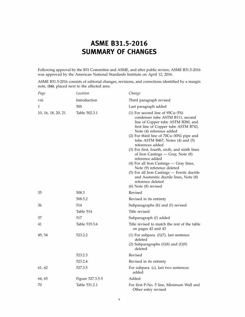
ASME B31.5-2016 consists of editorial changes, revisions, and corrections identified by a marginnote, (16), placed next to the affected area.
Page Location Change
viii Introduction Third paragraph revised
1 500 Last paragraph added
10, 16, 18, 20, 21 Table 502.3.1 (1) For second line of 95Cu–5Nicondenser tube ASTM B111, secondline of Copper tube ASTM B280, andfirst line of Copper tube ASTM B743,Note (4) reference added
(2) For third line of 70Cu–30Ni pipe andtube ASTM B467, Notes (4) and (5)references added
(3) For first, fourth, sixth, and ninth linesof Iron Castings — Gray, Note (8)reference added
(4) For all Iron Castings — Gray lines,Note (9) reference deleted
(5) For all Iron Castings — Ferritc ductileand Austenitic ductile lines, Note (8)reference deleted
(6) Note (8) revised
35 508.3 Revised
508.5.2 Revised in its entirety
36 514 Subparagraphs (b) and (f) revised
Table 514 Title revised
37 517 Subparagraph (f) added
41 Table 519.3.6 Title revised to match the rest of the tableon pages 42 and 43
49, 54 523.2.2 (1) For subpara. (f)(7), last sentencedeleted
(2) Subparagraphs (f)(8) and (f)(9)deleted
523.2.3 Revised
523.2.4 Revised in its entirety
61, 62 527.3.5 For subpara. (c), last two sentencesadded
64, 65 Figure 527.3.5-5 Added
70 Table 531.2.1 For first P-No. 5 line, Minimum Wall andOther entry revised
x
(16)
ASME B31.5-2016
REFRIGERATION PIPING AND HEAT TRANSFER COMPONENTS
Chapter IScope and Definitions
500 GENERAL STATEMENTS
This Refrigeration Piping and Heat TransferComponents Code is a Section of the American Societyof Mechanical Engineers Code for Pressure Piping, B31.This Section is published as a separate document forsimplicity and for convenience of Code users. The usersof this Code are advised that in some areas legislationmay establish governmental jurisdiction over the subjectmatter covered by the Code. The owner of a pipinginstallation shall choose which piping code(s) are appli-cable to the installation and shall have the overallresponsibility for compliance with this Code. (SeeNonmandatory Appendix C.) The owner of a completepiping installation shall have the overall responsibilityfor compliance with this Code.
It is required that the engineering design specify anyspecial requirements pertinent to the particular serviceinvolved. For example, the engineering design shall notfor any service specify a weld quality lower than thatstipulated in para. 527.3.2(d) for the Code-requiredvisual examination quality and for the types of weldsinvolved; but where service requirements necessitateadded quality and more extensive nondestructive exam-ination, these are to be specified in the engineeringdesign and any revision thereto, and when so specified,the Code requires that they be accomplished.
The Code generally employs a simplified approachfor many of its requirements. A designer may choose touse a more complete and rigorous analysis to developdesign and construction requirements. When thedesigner decides to take this approach, the designer shallprovide details and calculations demonstrating thatdesign, contruction, examination, and testing are con-sistent with the criteria of this Code. The details shallbe documented in the engineering design.
500.1 Scope
Rules for this Code Section have been developed con-sidering the needs for applications that include pipingand heat transfer components for refrigerants and sec-ondary coolants.
1
500.1.1 This Code prescribes requirements for thematerials, design, fabrication, assembly, erection, test,and inspection of refrigerant, heat transfer components,and secondary coolant piping for temperatures as lowas −320°F (−196°C), whether erected on the premises orfactory assembled, except as specifically excluded in thefollowing paragraphs.
500.1.3 This Code shall not apply to any of thefollowing:
(a) any self-contained or unit systems subject to therequirements of Underwriters Laboratories or othernationally recognized testing laboratory
(b) water piping, other than where water is used asa secondary coolant or refrigerant
(c) piping designed for external or internal gage pres-sure not exceeding 15 psi (105 kPa) regardless of size
(d) pressure vessels, compressors, or pumps, but doesinclude all connecting refrigerant and secondary coolantpiping starting at the first joint adjacent to suchapparatus
500.2 Definitions
For convenience in reference, some of the more com-mon terms relating to piping are defined in thissubdivision.
Most welding definitions were taken from the AWSWelding Handbook, Volume 1, 7th Edition. Heat treat-ment terms were taken from ASM Metals HandbookProperties and Selection of Materials, Volume 1,8th Edition.
arc welding: a group of welding processes wherein coales-cence is produced by heating with an electric arc(s),with or without the application of pressure and with orwithout the use of filler metal.
automatic welding: welding with equipment that per-forms the entire welding operation without constantobservation and adjustment of the controls by an opera-tor. The equipment may or may not perform the loadingand unloading of the work.
backing ring: backing in the form of a ring generally usedin the welding of piping.
ASME B31.5-2016
base metal: the metal to be welded, soldered, brazed,or cut.
brazing: a joining process that produces coalescence ofmaterials by heating them in the presence of a fillermetal having a liquidus above 840°F (450°C) but belowthe solidus of the base metals. Heating may be providedby a variety of processes. The filler metal distributesitself between the closely fitted surfaces of the joint bycapillary action. Brazing differs from soldering in thatsoldering filler metals have a liquidus below 840°F(450°C).
brine: a secondary coolant that is a solution of a salt andwater.
butt joint: an assembly of two members lying approxi-mately in the same plane.
compressor: a specific machine, with or without accesso-ries, for compressing a given refrigerant vapor.
condenser: that part of a refrigerating system designedto liquefy refrigerant vapor by the removal of heat.
condenser coil: a condenser constructed of pipe or tube,not enclosed in a pressure vessel.
design pressure: see section 501.
engineering design: the detailed design developed fromprocess requirements and conforming to Code require-ments, including all necessary drawings and specifica-tions, governing a piping installation.
equipment connection: an integral part of such equipmentas pressure vessels, heat exchangers, and pumps,designed for attachment to pipe or piping components.
evaporator: that part of a refrigerating system designedto vaporize liquid refrigerant to produce refrigeration.
evaporator coil: an evaporator constructed of pipe or tube,not enclosed in a pressure vessel.
face of weld: the exposed surface of a weld on the sidefrom which the welding was done.
filler metal: metal to be added in making a welded,brazed, or soldered joint.
fillet weld: a weld of approximately triangular cross-section joining two surfaces approximately at rightangles to each other in a lap joint, tee joint, corner joint,or socket joint.
fusion: see weld.
gas metal-arc welding (GMAW): an arc welding processwherein coalescence is produced by heating with an arcbetween a continuous filler metal (consumable) elec-trode and the work. Shielding is obtained entirely froman externally supplied gas or gas mixture. (Some meth-ods of this process are called MIG or CO2 welding.)
gas tungsten-arc welding (GTAW): an arc welding processwherein coalescence is produced by heating with an arcbetween a single tungsten (nonconsumable) electrode
2
and the work. Shielding is obtained from a gas or gasmixture. Pressure may or may not be used and fillermetal may or may not be used. (This process is some-times called TIG welding.)
gas welding: a group of welding processes whereincoalescence is produced by heating with a gas flame orflames, with or without the application of pressure, andwith or without the use of filler metal.
groove weld: a weld made in the groove between twomembers to be joined.
header: a pipe or tube (extruded, cast or fabricated) towhich a number of other pipes or tubes are connected.
heat affected zone: that portion of the base metal that hasnot been melted, but whose mechanical properties ormicrostructures have been altered by the heat of weld-ing, brazing, or cutting.
heat transfer component: the pressure containing portionof equipment used for heat transfer including pipes,tubes, coils, or other components and their headers notconstructed as pressure vessels. (See also evaporator coiland condenser coil.)
heat treatmentannealing, full: heating a ferrous alloy into the austeni-
tizing transformation temperature range, holding abovethat range for a proper period of time, followed bycooling slowly through the transformation range.
austenitizing: forming austenite by heating a ferrousalloy into the transformation range (partial austenitiz-ing) or above the transformation range (completeaustenitizing).
normalizing: heating a ferrous alloy to a suitable tem-perature above the transformation range and subse-quently cooling in air to a temperature substantiallybelow the transformation range.
stress-relief: uniform heating of a structure or portionthereof to a sufficient temperature below the criticalrange to relieve the major portion of the residual stresses,and then cooling slowly enough to minimize the devel-opment of new residual stresses.
transformation range: the ranges of temperature withinwhich austenite forms during heating and transformsto martensite or other microstructure during cooling.The limiting temperatures of the range are determinedby composition of the ally and on the rate of change oftemperature, particularly on cooling wherein the trans-formation reaction is lower for rapid quench rates.
high side: the parts of a refrigerating system subjectedto condenser pressure.
joint design: the joint geometry together with the requireddimensions of the welded joint.
joint penetration: the minimum depth a groove or flangeweld extends from its face into a joint, exclusive ofreinforcement.
ASME B31.5-2016
limited charge system: a system in which, with the com-pressor idle, the internal volume and total refrigerantcharge are such that the design pressure will not beexceeded by complete evaporation of the refrigerantcharge.
low side: the parts of a refrigerating system subjected toevaporator pressure.
manual welding: welding wherein the entire weldingoperation is performed and controlled by hand.
mechanical joint: a joint obtained by joining of metal partsthrough a positive holding mechanical construction.
miter joint: two or more straight sections of pipe matchedand joined on a plane bisecting the angle or junction soas to produce a change in direction.
nominal: a numerical identification of dimension, capac-ity, rating, or other characteristic used as a designation,not as an exact measurement.
peening: the mechanical working of metals by means ofimpact blows.
pipe: a tubular component, usually cylindrical, used forconveying fluid and normally designated “pipe” in theapplicable specification. It also includes similar compo-nents designated “tube.” Types of welded pipe,according to the method of manufacture, are defined asfollows:
double submerged-arc welded: pipe having a longitudinalbutt joint produced by at least two passes, one of whichis on the inside of the pipe. Coalescence is produced byheating with an electric arc or arcs between the baremetal electrode or electrodes and the work. The weldingis shielded by a blanket of granular, fusible material onthe work. Pressure is not used and filler metal for theinside and outside welds is obtained from the electrodeor electrodes.
electric-flash welded: pipe having a longitudinal buttjoint wherein coalescence is produced, simultaneouslyover the entire area of abutting surfaces, by the heatobtained from resistance to the flow of electric currentbetween the two surfaces, and by the application ofpressure after heating is substantially completed. Flash-ing and upsetting are accompanied by expulsion ofmetal from the joint.
electric-fusion welded: pipe having a longitudinal orspiral butt joint wherein coalescence is produced in thepreformed tube by manual or automatic electric-arcwelding. The weld may be single or double and may bemade with or without the use of filler metal. Spiralwelded pipe is also made by the electric-fusion weldedprocess with either a lap joint or a lock-seam joint.
electric-resistance welded: pipe produced in individuallengths, or in continuous lengths from coiled skelp andsubsequently cut into individual lengths, having a longi-tudinal or spiral butt joint wherein coalescence is pro-duced by the heat obtained from resistance of the pipe
3
to the flow of electric current in a circuit of which thepipe is a part, and by the application of pressure.
furnace butt welded, continuous welded: pipe producedin continuous lengths from coiled skelp heated toapproximately 2,500°F (1 371°C). Immediately afterforming, the pipe edges are superheated by an oxygenlance to near the melting point. A weld forming rollapplies sufficient lateral force to extrude the cast weldmetal to the I.D. and O.D. It is then reduced by a seriesof horizontal and vertical rolls to its final size.
pipe supporting elements: elements that consist of fixturesand structural attachments. They do not include supportstructures and equipment, such as stanchions, towers,building frames, pressure vessels, mechanical equip-ment, and foundations.
fixtures: elements that transfer the load from the pipeor structural attachment to the supporting structure orequipment. They include hanging-type fixtures, such ashanger rods, spring hangers, sway braces, counter-weights, turnbuckles, struts, chains, guides, anchors,and bearing type fixtures, such as saddles, bases, rollers,brackets, and sliding supports.
structural attachments: elements that are welded,bolted, or clamped to the pipe, such as clips, lugs, rings,clamps, clevises, straps, and skirts.
piping: the pipe and tube for interconnecting the variousparts in a refrigeration system, which includes pipe,tube, flanges, bolting, gaskets, valves, and fittings; otherpressure-containing parts, such as heat transfer compo-nents, expansion joints, strainers, and filters; devices thatserve such purposes as mixing, separating, snubbing,distributing, metering, or controlling flow; and pipe sup-porting elements.
postheating: the application of heat to an assembly aftera welding, brazing, soldering, or cutting operation.
preheating: the application of heat to the base metalimmediately before a welding, brazing, soldering, orcutting operation.
premises: the buildings and that part of the grounds ofone property, where an installation would affect thesafety of those buildings or adjacent property.
pressure vessel: see Section VIII, Division 1, ASME Boilerand Pressure Vessel Code (hereinafter referred to as theASME BPV Code).
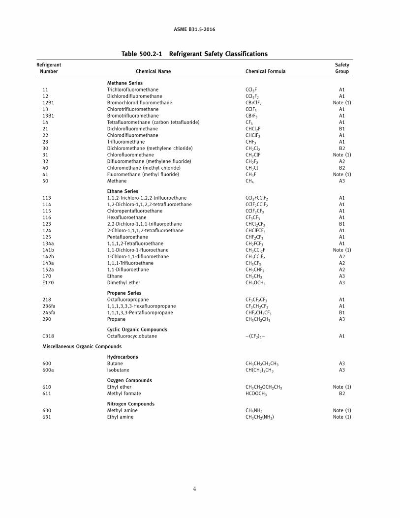
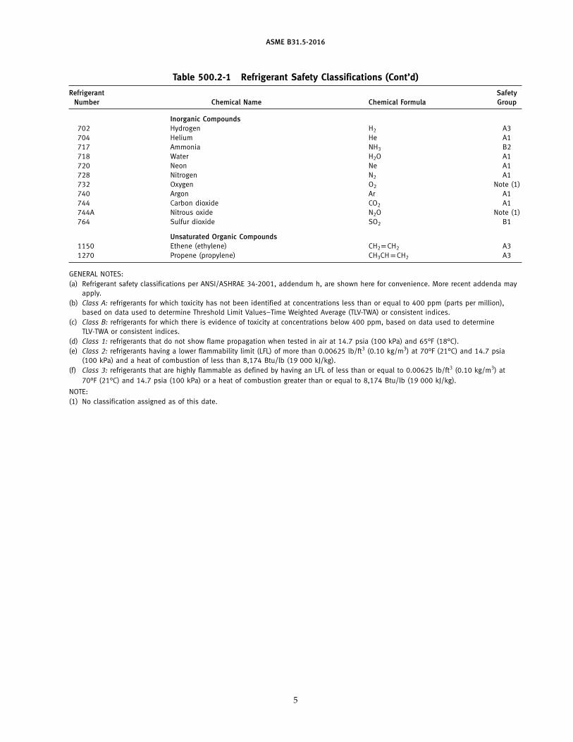
refrigerant and refrigerant mixtures: the fluid used for heattransfer in a refrigerating system that absorbs heat dur-ing evaporation at low temperature and pressure, andreleases heat during condensation at a higher tempera-ture and pressure. The safety classification group con-sists of two characters (e.g., A1 or B2). The capital letterindicates the toxicity and the arabic numeral indicatesthe flammability, based on the criteria in Tables 500.2-1and 500.2-2.
ASME B31.5-2016
Table 500.2-1 Refrigerant Safety Classifications
Refrigerant SafetyNumber Chemical Name Chemical Formula Group
Methane Series11 Trichlorofluoromethane CCl3F A112 Dichlorodifluoromethane CCl2F2 A112B1 Bromochlorodifluoromethane CBrClF2 Note (1)13 Chlorotrifluoromethane CClF3 A113B1 Bromotrifluoromethane CBrF3 A114 Tetrafluoromethane (carbon tetrafluoride) CF4 A121 Dichlorofluoromethane CHCl2F B122 Chlorodifluoromethane CHClF2 A123 Trifluoromethane CHF3 A130 Dichloromethane (methylene chloride) CH2Cl2 B231 Chlorofluoromethane CH2ClF Note (1)32 Difluoromethane (methylene fluoride) CH2F2 A240 Chloromethane (methyl chloride) CH3Cl B241 Fluoromethane (methyl fluoride) CH3F Note (1)50 Methane CH4 A3
Ethane Series113 1,1,2-Trichloro-1,2,2-trifluoroethane CCl2FCClF2 A1114 1,2-Dichloro-1,1,2,2-tetrafluoroethane CClF2CClF2 A1115 Chloropentafluoroethane CClF2CF3 A1116 Hexafluoroethane CF3CF3 A1123 2,2-Dichloro-1,1,1-trifluoroethane CHCl2CF3 B1124 2-Chloro-1,1,1,2-tetrafluoroethane CHClFCF3 A1125 Pentafluoroethane CHF2CF3 A1134a 1,1,1,2-Tetrafluoroethane CH2FCF3 A1141b 1,1-Dichloro-1-fluoroethane CH3CCl2F Note (1)142b 1-Chloro-1,1-difluoroethane CH3CClF2 A2143a 1,1,1-Trifluoroethane CH3CF3 A2152a 1,1-Difluoroethane CH3CHF2 A2170 Ethane CH3CH3 A3E170 Dimethyl ether CH3OCH3 A3
Propane Series218 Octafluoropropane CF3CF2CF3 A1236fa 1,1,1,3,3,3-Hexafluoropropane CF3CH2CF3 A1245fa 1,1,1,3,3-Pentafluoropropane CHF2CH2CF3 B1290 Propane CH3CH2CH3 A3
Cyclic Organic CompoundsC318 Octafluorocyclobutane –(CF2)4– A1
Miscellaneous Organic Compounds
Hydrocarbons600 Butane CH3CH2CH2CH3 A3600a Isobutane CH(CH3)2CH3 A3
Oxygen Compounds610 Ethyl ether CH3CH2OCH2CH3 Note (1)611 Methyl formate HCOOCH3 B2
Nitrogen Compounds630 Methyl amine CH3NH2 Note (1)631 Ethyl amine CH3CH2(NH2) Note (1)
4
ASME B31.5-2016
Table 500.2-1 Refrigerant Safety Classifications (Cont’d)
Refrigerant SafetyNumber Chemical Name Chemical Formula Group
Inorganic Compounds702 Hydrogen H2 A3704 Helium He A1717 Ammonia NH3 B2718 Water H2O A1720 Neon Ne A1728 Nitrogen N2 A1732 Oxygen O2 Note (1)740 Argon Ar A1744 Carbon dioxide CO2 A1744A Nitrous oxide N2O Note (1)764 Sulfur dioxide SO2 B1
Unsaturated Organic Compounds1150 Ethene (ethylene) CH2pCH2 A31270 Propene (propylene) CH3CHpCH2 A3
GENERAL NOTES:(a) Refrigerant safety classifications per ANSI/ASHRAE 34-2001, addendum h, are shown here for convenience. More recent addenda may
apply.(b) Class A: refrigerants for which toxicity has not been identified at concentrations less than or equal to 400 ppm (parts per million),
based on data used to determine Threshold Limit Values–Time Weighted Average (TLV-TWA) or consistent indices.(c) Class B: refrigerants for which there is evidence of toxicity at concentrations below 400 ppm, based on data used to determine
TLV-TWA or consistent indices.(d) Class 1: refrigerants that do not show flame propagation when tested in air at 14.7 psia (100 kPa) and 65°F (18°C).(e) Class 2: refrigerants having a lower flammability limit (LFL) of more than 0.00625 lb/ft3 (0.10 kg/m3) at 70°F (21°C) and 14.7 psia
(100 kPa) and a heat of combustion of less than 8,174 Btu/lb (19 000 kJ/kg).(f) Class 3: refrigerants that are highly flammable as defined by having an LFL of less than or equal to 0.00625 lb/ft3 (0.10 kg/m3) at
70°F (21°C) and 14.7 psia (100 kPa) or a heat of combustion greater than or equal to 8,174 Btu/lb (19 000 kJ/kg).
NOTE:(1) No classification assigned as of this date.
5
ASME B31.5-2016
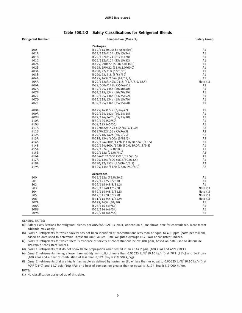
Table 500.2-2 Safety Classifications for Refrigerant Blends
Refrigerant Number Composition (Mass %) Safety Group
Zeotropes400 R-12/114 (must be specified) A1401A R-22/152a/124 (53/13/34) A1401B R-22/152a/124 (61/11/28) A1401C R-22/152a/124 (33/15/52) A1402A R-125/290/22 (60.0/2.0/38.0) A1402B R-125/290/22 (38.0/2.0/60.0) A1403A R-290/22/218 (5/75/20) A1403B R-290/22/218 (5/56/39) A1404A R-125/143a/134a (44/52/4) A1405A R-22/152a/142b/C318 (45/7/5.5/42.5) Note (1)406A R-22/600a/142b (55/4/41) A2407A R-32/125/134a (20/40/40) A1407B R-32/125/134a (10/70/20) A1407C R-32/125/134a (23/25/52) A1407D R-32/125/134a (15/15/70) A1407E R-32/125/134a (25/15/60) A1
408A R-125/143a/22 (7/46/47) A1409A R-22/124/142b (60/25/15) A1409B R-22/124/142b (65/25/10) A1410A R-32/125 (50/50) A1410B R-32/125 (45/55) A1411A R-1270/22/152a (1.5/87.5/11.0) A2411B R-1270/22/152a (3/94/3) A2412A R-22/218/142b (70/5/25) A2413A R-218/134a/600a (9/88/3) A2414A R-22/124/600a/142b (51.0/28.5/4.0/16.5) A1414B R-22/124/600a/142b (50.0/39.0/1.5/9.5) A1415A R-22/152a (82.0/18.0) A2415B R-22/152a (25.0/75.0) A2416A R-134a/124/600 (59.0/39.5/1.5) A1417A R-125/134a/600 (46.6/50.0/3.4) A1418A R-290/22/152a (1.5/96.0/2.5) A2419A R-125/134a/E170 (77.0/19.0/4.0) A2
Azeotropes500 R-12/152a (73.8/26.2) A1501 R-22/12 (75.0/25.0) A1502 R-22/115 (48.8/51.2) A1503 R-23/13 (40.1/59.9) Note (1)504 R-32/115 (48.2/51.8) Note (1)505 R-12/31 (78.0/22.0) Note (1)506 R-31/114 (55.1/44.9) Note (1)507A R-125/143a (50/50) A1508A R-23/116 (39/61) A1508B R-23/116 (46/54) A1509A R-22/218 (44/56) A1
GENERAL NOTES:(a) Safety classifications for refrigerant blends per ANSI/ASHRAE 34-2001, addendum h, are shown here for convenience. More recent
addenda may apply.(b) Class A: refrigerants for which toxicity has not been identified at concentrations less than or equal to 400 ppm (parts per million),
based on data used to determine Threshold Limit Values–Time Weighted Average (TLV-TWA) or consistent indices.(c) Class B: refrigerants for which there is evidence of toxicity at concentrations below 400 ppm, based on data used to determine
TLV-TWA or consistent indices.(d) Class 1: refrigerants that do not show flame propagation when tested in air at 14.7 psia (100 kPa) and 65°F (18°C).(e) Class 2: refrigerants having a lower flammability limit (LFL) of more than 0.00625 lb/ft3 (0.10 kg/m3) at 70°F (21°C) and 14.7 psia
(100 kPa) and a heat of combustion of less than 8,174 Btu/lb (19 000 kJ/kg).(f) Class 3: refrigerants that are highly flammable as defined by having an LFL of less than or equal to 0.00625 lb/ft3 (0.10 kg/m3) at
70°F (21°C) and 14.7 psia (100 kPa) or a heat of combustion greater than or equal to 8,174 Btu/lb (19 000 kJ/kg).
NOTE:(1) No classification assigned as of this date.
6
ASME B31.5-2016
refrigerating system: a combination of interconnectingrefrigerant-containing parts constituting a closed refrig-erant circuit in which a refrigerant is circulated for thepurpose of extracting heat.
reinforcement of weld: weld metal in excess of the specifiedweld size.
root opening: the separation between the members to bejoined, at the root of the joint.
root penetration: the depth a groove weld extends intothe root of a joint measured on the centerline of the rootcross section.
seal weld: any weld used primarily to provide a specificdegree of tightness against leakage.
secondary coolant: any liquid used for the transmissionof heat without a change in its state.
self-contained system: a complete factory-made andfactory-tested system in a suitable frame or enclosurethat is fabricated and shipped in one or more sectionsand in which no refrigerant-containing parts are con-nected in the field other than by companion flanges orblock valves.
semiautomatic arc welding: arc welding with equipmentthat controls only the filler metal feed. The advance ofthe welding is manually controlled.
shall: where “shall” or “shall not” is used for a provisionspecified, that provision is intended to be a Coderequirement.
shielded metal-arc welding (SMAW): an arc welding pro-cess wherein coalescence is produced by heating withan electric arc between a covered metal electrode andthe work. Shielding is obtained from decomposition ofthe electrode covering. Pressure is not used, and fillermetal is obtained from the electrode.
should: “should” or “it is recommended” is used to indi-cate provisions that are not mandatory but recom-mended good practice.
size of weldequal leg fillet weld: the leg lengths of the largest isosce-
les right triangle that can be inscribed within the filletweld cross-section.
groove weld: the joint penetration (depth of chamferingplus the root penetration when specified). The size ofthe groove weld and its effective throat are one andthe same.
unequal leg fillet weld: the leg lengths of the largestright triangle that can be inscribed within the fillet weldcross-section.
slag inclusion: nonmetallic solid material entrapped inweld metal or between weld metal and base metal.
soldering: a joining process that produces coalescence ofmaterials by heating them to a suitable temperature and
7
by using a filler metal having a liquidus not exceeding840°F (450°C) and below the solidus of the base materi-als. The filler metal is distributed between the closelyfitted surfaces of the joint by capillary action. Solderingmay be performed manually, ultrasonically, or in afurnace.
submerged arc welding (SAW): an arc welding processwherein coalescence is produced by heating an arc(s)between a bare metal electrode or electrodes and thework. The arc is shielded by a blanket of granular fusiblematerial on the work. Pressure is not used and fillermetal is obtained from the electrode and sometimesfrom a supplementary welding rod.
tack weld: a weld made to hold parts of a weldment inproper alignment until the final welds are made.
throat of a fillet weldactual: the shortest distance from the root of a fillet
weld to its face.effective: the minimum distance from the root of a weld
to its face, less any reinforcement.theoretical: the distance from the beginning of the root
of the joint perpendicular to the hypotenuse of the larg-est right triangle that can be inscribed within the fillet-weld cross-section.
toe of weld: the junction between the face of the weldand the base metal.
tube: see pipe.
undercut: a groove melted into the base metal adjacentto the toe or root of a weld and left unfilled by weldmetal.
weld: a localized coalescence of metals or nonmetals pro-duced by heating the materials to suitable temperatures,with or without the application of pressure, and withor without the use of filler metal.
welder: one who is capable of performing a manual orsemiautomatic welding operation.
welding operator: one who operates machine or automaticwelding equipment.
welding procedures: the detailed methods and practicesincluding all joint welding procedures involved in theproduction of a weldment.
weldment: an assembly whose component parts arejoined by welding.
500.3 Nomenclature
Dimensional and mathematical symbols used in thisCode are listed in Nonmandatory Appendix D, withdefinitions and location references to each. Uppercaseand lowercase English letters are listed alphabetically,followed by Greek letters.
ASME B31.5-2016
Chapter IIDesign
PART 1CONDITIONS AND CRITERIA
501 DESIGN CONDITIONS
501.1 General
Section 501 defines the temperatures, pressures, andvarious forces applicable to the design of piping systems.It also states considerations that shall be given to ambi-ent and mechanical influences and various loadings.
501.2 Pressure
501.2.2 Internal Design Pressure. The piping com-ponent shall be designed for an internal pressure repre-senting the most severe condition of coincident pressureand temperature expected in normal operation orstandby (including fluid head). The most severe condi-tion of coincident pressure and temperature shall bethat condition that results in the greater required pipingcomponent thickness and the highest component rating.
Any piping connected to components other than pip-ing shall have a design pressure no less than the lowestdesign pressure of any component to which it isconnected.
501.2.3 External Design Pressure. The piping com-ponent shall be designed for an external pressure repre-senting the most severe condition of coincident pressureand temperature expected during shutdown or in nor-mal operation (including fluid head) considering possi-ble loss of internal pressure. Refrigerant piping systemsshall be designed to resist collapse when the internalpressure is zero absolute and the external pressure isatmospheric. This is to permit drying the pipe by evacua-tion. The most severe condition of coincident pressureand temperature shall be that condition that results inthe greatest required pipe thickness and the highest com-ponent rating.
501.2.4 Minimum Design Pressure. Minimumdesign gage pressure shall be not less than 15 psi(105 kPa) and, except as noted in para. 501.2.5, shall benot less than the saturation pressure of the refrigerantat the following temperatures:
(a) low sides of all systems: 80°F (27°C)(b) high side of water or evaporatively cooled sys-
tems: 104°F (40°C)(c) high sides of air cooled systems: 122°F (50°C)Considerations shall be given to low side systems
with hot gas defrost. Such systems impose high side
8
pressure on the low side during the defrost cycle. Thismay raise the low side design pressure requirements.
501.2.5 Minimum Design Pressure for SpecificService
(a) Design pressure for either high or low side neednot exceed the critical pressure of the refrigerant unlessthe system is intended to operate at these conditions.
(b) When components of a system are protected by apressure relief device, the design pressure of the pipingneed not exceed the setting of the pressure relief device.
(c) In a compound system the piping between stagesshall be considered the low side of the next higher stagecompressor.
501.3 Temperature
In this Code, metal temperature of piping in service isconsidered to be the temperature of the fluid conveyed.
501.3.1 Brittle Fracture. Consideration must begiven to a reduction in impact strength occurring insome materials when subjected to low temperatures.Notch effects should be avoided (see para. 523.2).
501.4 Ambient Influences
501.4.1 Ambient Temperature. In the design ofrefrigeration piping systems, consideration must begiven to the influence of ambient temperature.
501.4.2 Fluid Expansion Effects (IncreasedPressure). Consideration must be given to expansionof liquid refrigerant trapped in or between closed valvesand a means provided to prevent overpressure.
501.5 Dynamic Effects
501.5.1 Impact. Impact forces, including hydraulicshock and liquid slugging, caused by either external orinternal conditions shall be considered in the design ofpiping components.
501.5.2 Wind. The effect of wind loading shouldbe taken into account in the design of exposed pipingas described in SEI/ASCE 7-05.
501.5.3 Earthquake (Seismic Forces). Piping sys-tems located in regions where earthquakes are a factorshall be designed for horizontal forces. The method ofanalysis may be as described in SEI/ASCE 7-05. How-ever, this force is not to be considered as acting concur-rently with lateral wind force.
ASME B31.5-2016
501.5.4 Vibration. Piping shall be arranged andsupported with consideration to vibration (seepara. 521.3.5).
501.5.5 Discharge Reactions. Piping systems shallbe designed, arranged, and supported so as to withstandreaction forces due to let down or discharge of fluids.
501.6 Weight Effects
The following weight effects combined with loads andforces from other causes shall be taken into account inthe design of piping.
501.6.1 Live Loads. The live load consists of theweight of the fluid transported, and snow and ice loads,if the latter will be encountered.
501.6.2 Dead Loads. Dead loads consist of theweight of the piping components and insulation, andother superimposed permanent loads.
501.6.3 Test Loads. The test load consists of theweight of the test fluid.
501.7 Thermal Expansion and Contraction Loads
When a piping system is prevented from free thermalexpansion and contraction as a result of anchors andrestraints, thrusts and moments are set up that must betaken into account as required by sections 502 and 519.Consideration must be given to stresses developedinside pipe walls by large rapid temperature changes ofthe contents.
502 DESIGN CRITERIA
502.1 General
Section 502 pertains to ratings, stress values, stresscriteria, design allowances, and minimum design values,and formulates the permissible variations to these fac-tors used in the design of piping.
502.2 Pressure–Temperature Design Criteria forPiping Components
502.2.1 Components Having Specific Ratings.Pressure–temperature ratings for certain piping compo-nents have been established and are contained in someof the standards listed in Table 526.1.
502.2.2 Ratings: Normal Operating Conditions. Fornormal operation the design pressure and design tem-perature shall be within the pressure–temperature rat-ings for all components used.
502.2.3 Ratings: Allowance for Variations FromNormal Operation. It is recognized that variations inpressure and temperature inevitably occur, and there-fore the piping system shall be considered safe for occa-sional operation for short periods at higher than thedesign pressure or temperature.
9
Either pressure or temperature, or both, may exceedthe design values if the stress in the pipe wall calculatedby the formulas using the maximum expected pressureduring the variation does not exceed the S value allow-able for the maximum expected temperature during thevariation by more than the following allowances for theperiods of duration indicated:
(a) up to 15% increase above the S value during 10%of the operating period
(b) up to 20% increase above the S value during 1%of the operating period
502.2.4 Considerations for Local Conditions andTransitions. When two lines that operate at differentpressure–temperature conditions are connected, thevalve segregating the two lines shall be rated for themore severe condition. When a line is connected to apiece of equipment that operates at a higher pressure–temperature condition than that of the line, the valvesegregating the line from the equipment shall be ratedfor at least the operating condition of the equipment. If,however, the valve is a sufficient distance from the pipeor piece of equipment operating under the more severeservice condition, with the result that the temperatureof this valve would be lower than the more severe servicecondition, this valve may be rated for the most severecoexistent pressure–temperature condition to which itwill be actually subjected in normal operation. However,the piping between the more severe conditions and thevalve shall be designed to withstand the operating con-ditions of the equipment or piping to which it isconnected.
502.2.5 Standards and Specifications. Where thereare manufacturers’ standards of long standing, as is thecase for flanges, valves, and fittings for certain refriger-ants, these shall be permitted for the particular refriger-ant service listed by the manufacturer.
502.2.6 Use of Criteria. The design conditions men-tioned in section 501 determine the thickness of metalor other material required in the piping system. Thisthickness can be determined by one of the followingthree methods:
(a) a combination of allowable stresses for the materi-als at the various temperature and mathematical formu-las that link together the design condition and thethickness of metal or other material required
(b) a pressure–temperature rating for the individualcomponents
(c) an outright requirement that certain standardizedcomponents be used or not be used
502.3 Allowable Stresses and Other Stress Limits
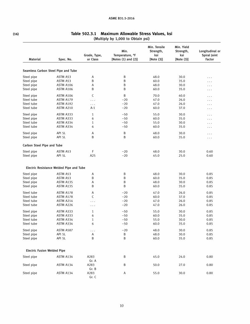
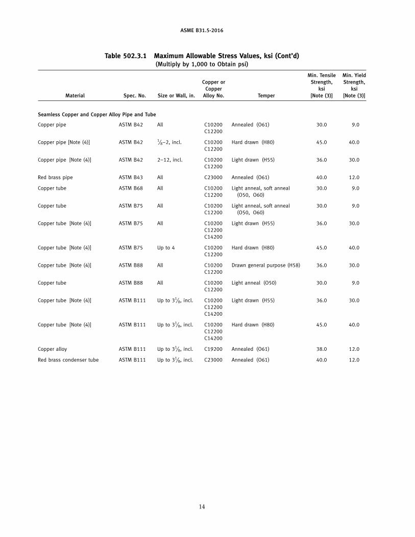
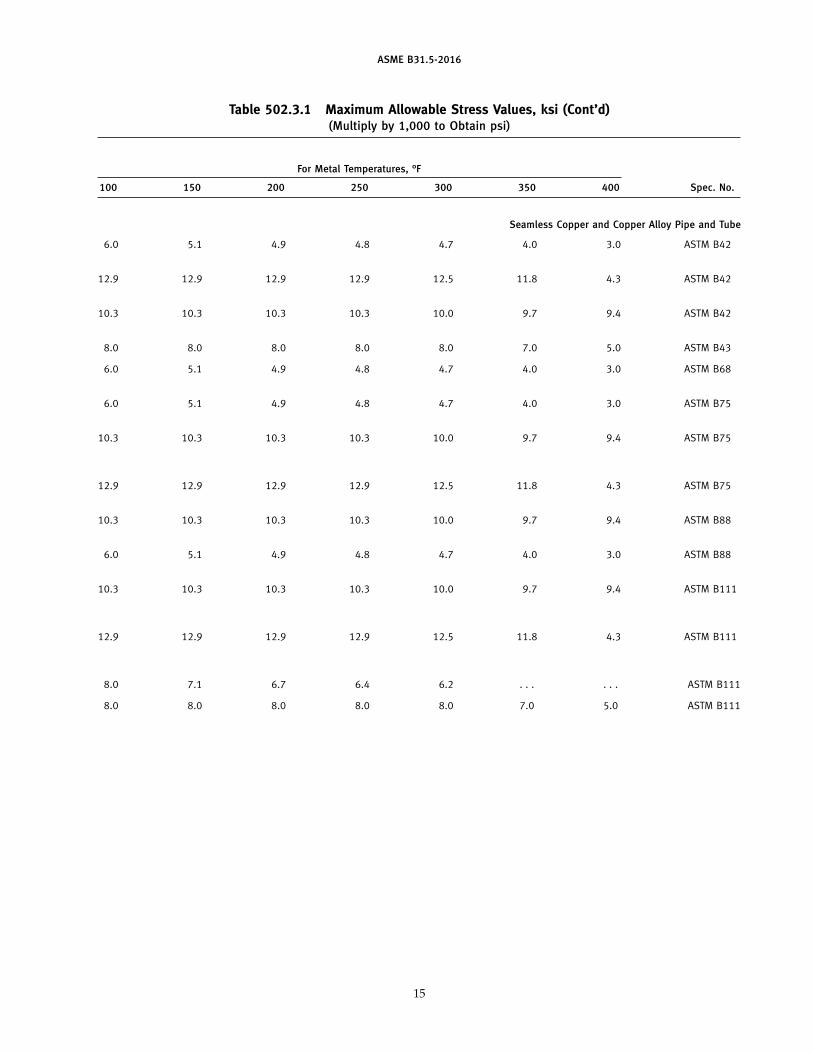
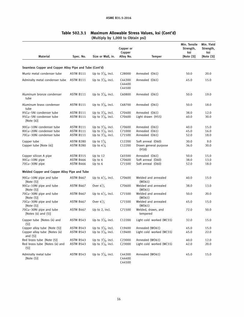
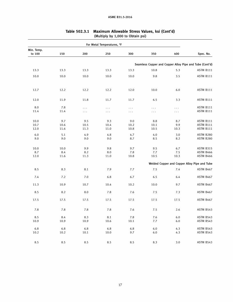
502.3.1 Allowable Stress Values(a) The allowable stress values to be used for design
calculations shall conform to Table 502.3.1 unless other-wise modified by requirements of this Code.
(16)
ASME B31.5-2016
Table 502.3.1 Maximum Allowable Stress Values, ksi(Multiply by 1,000 to Obtain psi)
Min. Tensile Min. YieldMin. Strength, Strength, Longitudinal or
Grade, Type, Temperature, °F ksi ksi Spiral JointMaterial Spec. No. or Class [Notes (1) and (2)] [Note (3)] [Note (3)] Factor
Seamless Carbon Steel Pipe and Tube
Steel pipe ASTM A53 A B 48.0 30.0 . . .Steel pipe ASTM A53 B B 60.0 35.0 . . .Steel pipe ASTM A106 A B 48.0 30.0 . . .Steel pipe ASTM A106 B B 60.0 35.0 . . .
Steel pipe ASTM A106 C B 70.0 40.0 . . .Steel tube ASTM A179 . . . −20 47.0 26.0 . . .Steel tube ASTM A192 . . . −20 47.0 26.0 . . .Steel tube ASTM A210 A-1 −20 60.0 37.0 . . .
Steel pipe ASTM A333 1 −50 55.0 30.0 . . .Steel pipe ASTM A333 6 −50 60.0 35.0 . . .Steel tube ASTM A334 1 −50 55.0 30.0 . . .Steel tube ASTM A334 6 −50 60.0 35.0 . . .
Steel pipe API 5L A B 48.0 30.0 . . .Steel pipe API 5L B B 60.0 35.0 . . .
Carbon Steel Pipe and Tube
Steel pipe ASTM A53 F −20 48.0 30.0 0.60Steel pipe API 5L A25 −20 45.0 25.0 0.60
Electric Resistance Welded Pipe and Tube
Steel pipe ASTM A53 A B 48.0 30.0 0.85Steel pipe ASTM A53 B B 60.0 35.0 0.85Steel pipe ASTM A135 A B 48.0 30.0 0.85Steel pipe ASTM A135 B B 60.0 35.0 0.85
Steel tube ASTM A178 A −20 47.0 26.0 0.85Steel tube ASTM A178 C −20 60.0 37.0 0.85Steel tube ASTM A214 . . . −20 47.0 26.0 0.85Steel tube ASTM A226 . . . −20 47.0 26.0 0.85
Steel pipe ASTM A333 1 −50 55.0 30.0 0.85Steel pipe ASTM A333 6 −50 60.0 35.0 0.85Steel tube ASTM A334 1 −50 55.0 30.0 0.85Steel tube ASTM A334 6 −50 60.0 35.0 0.85
Steel pipe ASTM A587 . . . −20 48.0 30.0 0.85Steel pipe API 5L A B 48.0 30.0 0.85Steel pipe API 5L B B 60.0 35.0 0.85
Electric Fusion Welded Pipe
Steel pipe ASTM A134 A283 B 45.0 24.0 0.80Gr. A
Steel pipe ASTM A134 A283 B 50.0 27.0 0.80Gr. B
Steel pipe ASTM A134 A283 A 55.0 30.0 0.80Gr. C
10
ASME B31.5-2016
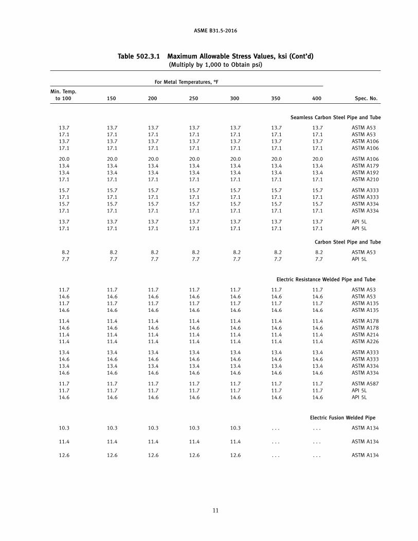
Table 502.3.1 Maximum Allowable Stress Values, ksi (Cont’d)(Multiply by 1,000 to Obtain psi)
For Metal Temperatures, °F
Min. Temp.to 100 150 200 250 300 350 400 Spec. No.
Seamless Carbon Steel Pipe and Tube
13.7 13.7 13.7 13.7 13.7 13.7 13.7 ASTM A5317.1 17.1 17.1 17.1 17.1 17.1 17.1 ASTM A5313.7 13.7 13.7 13.7 13.7 13.7 13.7 ASTM A10617.1 17.1 17.1 17.1 17.1 17.1 17.1 ASTM A106
20.0 20.0 20.0 20.0 20.0 20.0 20.0 ASTM A10613.4 13.4 13.4 13.4 13.4 13.4 13.4 ASTM A17913.4 13.4 13.4 13.4 13.4 13.4 13.4 ASTM A19217.1 17.1 17.1 17.1 17.1 17.1 17.1 ASTM A210
15.7 15.7 15.7 15.7 15.7 15.7 15.7 ASTM A33317.1 17.1 17.1 17.1 17.1 17.1 17.1 ASTM A33315.7 15.7 15.7 15.7 15.7 15.7 15.7 ASTM A33417.1 17.1 17.1 17.1 17.1 17.1 17.1 ASTM A334
13.7 13.7 13.7 13.7 13.7 13.7 13.7 API 5L17.1 17.1 17.1 17.1 17.1 17.1 17.1 API 5L
Carbon Steel Pipe and Tube
8.2 8.2 8.2 8.2 8.2 8.2 8.2 ASTM A537.7 7.7 7.7 7.7 7.7 7.7 7.7 API 5L
Electric Resistance Welded Pipe and Tube
11.7 11.7 11.7 11.7 11.7 11.7 11.7 ASTM A5314.6 14.6 14.6 14.6 14.6 14.6 14.6 ASTM A5311.7 11.7 11.7 11.7 11.7 11.7 11.7 ASTM A13514.6 14.6 14.6 14.6 14.6 14.6 14.6 ASTM A135
11.4 11.4 11.4 11.4 11.4 11.4 11.4 ASTM A17814.6 14.6 14.6 14.6 14.6 14.6 14.6 ASTM A17811.4 11.4 11.4 11.4 11.4 11.4 11.4 ASTM A21411.4 11.4 11.4 11.4 11.4 11.4 11.4 ASTM A226
13.4 13.4 13.4 13.4 13.4 13.4 13.4 ASTM A33314.6 14.6 14.6 14.6 14.6 14.6 14.6 ASTM A33313.4 13.4 13.4 13.4 13.4 13.4 13.4 ASTM A33414.6 14.6 14.6 14.6 14.6 14.6 14.6 ASTM A334
11.7 11.7 11.7 11.7 11.7 11.7 11.7 ASTM A58711.7 11.7 11.7 11.7 11.7 11.7 11.7 API 5L14.6 14.6 14.6 14.6 14.6 14.6 14.6 API 5L
Electric Fusion Welded Pipe
10.3 10.3 10.3 10.3 10.3 . . . . . . ASTM A134
11.4 11.4 11.4 11.4 11.4 . . . . . . ASTM A134
12.6 12.6 12.6 12.6 12.6 . . . . . . ASTM A134
11
ASME B31.5-2016
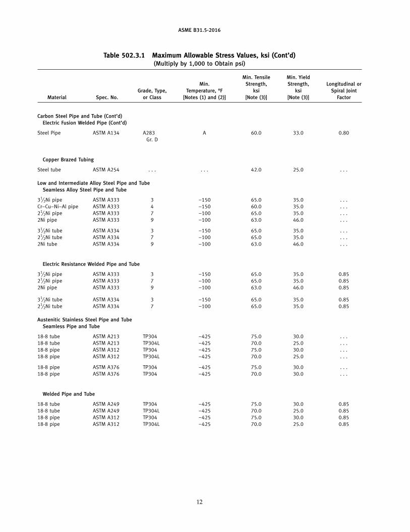
Table 502.3.1 Maximum Allowable Stress Values, ksi (Cont’d)(Multiply by 1,000 to Obtain psi)
Min. Tensile Min. YieldMin. Strength, Strength, Longitudinal or
Grade, Type, Temperature, °F ksi ksi Spiral JointMaterial Spec. No. or Class [Notes (1) and (2)] [Note (3)] [Note (3)] Factor
Carbon Steel Pipe and Tube (Cont’d)Electric Fusion Welded Pipe (Cont’d)
Steel Pipe ASTM A134 A283 A 60.0 33.0 0.80Gr. D
Copper Brazed Tubing
Steel tube ASTM A254 . . . . . . 42.0 25.0 . . .
Low and Intermediate Alloy Steel Pipe and TubeSeamless Alloy Steel Pipe and Tube
31⁄2Ni pipe ASTM A333 3 −150 65.0 35.0 . . .Cr–Cu–Ni–Al pipe ASTM A333 4 −150 60.0 35.0 . . .21⁄2Ni pipe ASTM A333 7 −100 65.0 35.0 . . .2Ni pipe ASTM A333 9 −100 63.0 46.0 . . .
31⁄2Ni tube ASTM A334 3 −150 65.0 35.0 . . .21⁄2Ni tube ASTM A334 7 −100 65.0 35.0 . . .2Ni tube ASTM A334 9 −100 63.0 46.0 . . .
Electric Resistance Welded Pipe and Tube
31⁄2Ni pipe ASTM A333 3 −150 65.0 35.0 0.8521⁄2Ni pipe ASTM A333 7 −100 65.0 35.0 0.852Ni pipe ASTM A333 9 −100 63.0 46.0 0.85
31⁄2Ni tube ASTM A334 3 −150 65.0 35.0 0.8521⁄2Ni tube ASTM A334 7 −100 65.0 35.0 0.85
Austenitic Stainless Steel Pipe and TubeSeamless Pipe and Tube
18-8 tube ASTM A213 TP304 −425 75.0 30.0 . . .18-8 tube ASTM A213 TP304L −425 70.0 25.0 . . .18-8 pipe ASTM A312 TP304 −425 75.0 30.0 . . .18-8 pipe ASTM A312 TP304L −425 70.0 25.0 . . .
18-8 pipe ASTM A376 TP304 −425 75.0 30.0 . . .18-8 pipe ASTM A376 TP304 −425 70.0 30.0 . . .
Welded Pipe and Tube
18-8 tube ASTM A249 TP304 −425 75.0 30.0 0.8518-8 tube ASTM A249 TP304L −425 70.0 25.0 0.8518-8 pipe ASTM A312 TP304 −425 75.0 30.0 0.8518-8 pipe ASTM A312 TP304L −425 70.0 25.0 0.85
12
ASME B31.5-2016
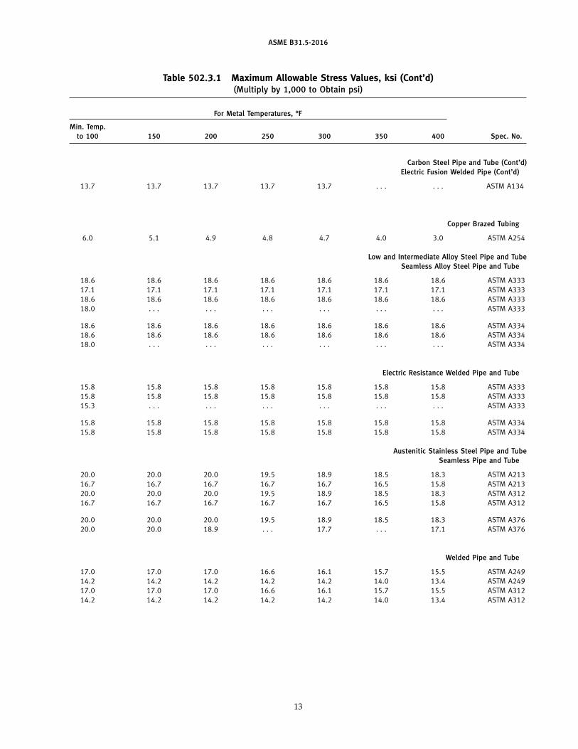
Table 502.3.1 Maximum Allowable Stress Values, ksi (Cont’d)(Multiply by 1,000 to Obtain psi)
For Metal Temperatures, °F
Min. Temp.to 100 150 200 250 300 350 400 Spec. No.
Carbon Steel Pipe and Tube (Cont’d)Electric Fusion Welded Pipe (Cont’d)
13.7 13.7 13.7 13.7 13.7 . . . . . . ASTM A134
Copper Brazed Tubing
6.0 5.1 4.9 4.8 4.7 4.0 3.0 ASTM A254
Low and Intermediate Alloy Steel Pipe and TubeSeamless Alloy Steel Pipe and Tube
18.6 18.6 18.6 18.6 18.6 18.6 18.6 ASTM A33317.1 17.1 17.1 17.1 17.1 17.1 17.1 ASTM A33318.6 18.6 18.6 18.6 18.6 18.6 18.6 ASTM A33318.0 . . . . . . . . . . . . . . . . . . ASTM A333
18.6 18.6 18.6 18.6 18.6 18.6 18.6 ASTM A33418.6 18.6 18.6 18.6 18.6 18.6 18.6 ASTM A33418.0 . . . . . . . . . . . . . . . . . . ASTM A334
Electric Resistance Welded Pipe and Tube
15.8 15.8 15.8 15.8 15.8 15.8 15.8 ASTM A33315.8 15.8 15.8 15.8 15.8 15.8 15.8 ASTM A33315.3 . . . . . . . . . . . . . . . . . . ASTM A333
15.8 15.8 15.8 15.8 15.8 15.8 15.8 ASTM A33415.8 15.8 15.8 15.8 15.8 15.8 15.8 ASTM A334
Austenitic Stainless Steel Pipe and TubeSeamless Pipe and Tube
20.0 20.0 20.0 19.5 18.9 18.5 18.3 ASTM A21316.7 16.7 16.7 16.7 16.7 16.5 15.8 ASTM A21320.0 20.0 20.0 19.5 18.9 18.5 18.3 ASTM A31216.7 16.7 16.7 16.7 16.7 16.5 15.8 ASTM A312
20.0 20.0 20.0 19.5 18.9 18.5 18.3 ASTM A37620.0 20.0 18.9 . . . 17.7 . . . 17.1 ASTM A376
Welded Pipe and Tube
17.0 17.0 17.0 16.6 16.1 15.7 15.5 ASTM A24914.2 14.2 14.2 14.2 14.2 14.0 13.4 ASTM A24917.0 17.0 17.0 16.6 16.1 15.7 15.5 ASTM A31214.2 14.2 14.2 14.2 14.2 14.0 13.4 ASTM A312
13
ASME B31.5-2016
Table 502.3.1 Maximum Allowable Stress Values, ksi (Cont’d)(Multiply by 1,000 to Obtain psi)
Min. Tensile Min. YieldCopper or Strength, Strength,
Copper ksi ksiMaterial Spec. No. Size or Wall, in. Alloy No. Temper [Note (3)] [Note (3)]
Seamless Copper and Copper Alloy Pipe and Tube
Copper pipe ASTM B42 All C10200 Annealed (O61) 30.0 9.0C12200
Copper pipe [Note (4)] ASTM B42 1⁄8–2, incl. C10200 Hard drawn (H80) 45.0 40.0C12200
Copper pipe [Note (4)] ASTM B42 2–12, incl. C10200 Light drawn (H55) 36.0 30.0C12200
Red brass pipe ASTM B43 All C23000 Annealed (O61) 40.0 12.0
Copper tube ASTM B68 All C10200 Light anneal, soft anneal 30.0 9.0C12200 (O50, O60)
Copper tube ASTM B75 All C10200 Light anneal, soft anneal 30.0 9.0C12200 (O50, O60)
Copper tube [Note (4)] ASTM B75 All C10200 Light drawn (H55) 36.0 30.0C12200C14200
Copper tube [Note (4)] ASTM B75 Up to 4 C10200 Hard drawn (H80) 45.0 40.0C12200
Copper tube [Note (4)] ASTM B88 All C10200 Drawn general purpose (H58) 36.0 30.0C12200
Copper tube ASTM B88 All C10200 Light anneal (O50) 30.0 9.0C12200
Copper tube [Note (4)] ASTM B111 Up to 31⁄8, incl. C10200 Light drawn (H55) 36.0 30.0C12200C14200
Copper tube [Note (4)] ASTM B111 Up to 31⁄8, incl. C10200 Hard drawn (H80) 45.0 40.0C12200C14200
Copper alloy ASTM B111 Up to 31⁄8, incl. C19200 Annealed (O61) 38.0 12.0
Red brass condenser tube ASTM B111 Up to 31⁄8, incl. C23000 Annealed (O61) 40.0 12.0
14
ASME B31.5-2016
Table 502.3.1 Maximum Allowable Stress Values, ksi (Cont’d)(Multiply by 1,000 to Obtain psi)
For Metal Temperatures, °F
100 150 200 250 300 350 400 Spec. No.
Seamless Copper and Copper Alloy Pipe and Tube
6.0 5.1 4.9 4.8 4.7 4.0 3.0 ASTM B42
12.9 12.9 12.9 12.9 12.5 11.8 4.3 ASTM B42
10.3 10.3 10.3 10.3 10.0 9.7 9.4 ASTM B42
8.0 8.0 8.0 8.0 8.0 7.0 5.0 ASTM B43
6.0 5.1 4.9 4.8 4.7 4.0 3.0 ASTM B68
6.0 5.1 4.9 4.8 4.7 4.0 3.0 ASTM B75
10.3 10.3 10.3 10.3 10.0 9.7 9.4 ASTM B75
12.9 12.9 12.9 12.9 12.5 11.8 4.3 ASTM B75
10.3 10.3 10.3 10.3 10.0 9.7 9.4 ASTM B88
6.0 5.1 4.9 4.8 4.7 4.0 3.0 ASTM B88
10.3 10.3 10.3 10.3 10.0 9.7 9.4 ASTM B111
12.9 12.9 12.9 12.9 12.5 11.8 4.3 ASTM B111
8.0 7.1 6.7 6.4 6.2 . . . . . . ASTM B111
8.0 8.0 8.0 8.0 8.0 7.0 5.0 ASTM B111
15
ASME B31.5-2016
Table 502.3.1 Maximum Allowable Stress Values, ksi (Cont’d)(Multiply by 1,000 to Obtain psi)
Min. Tensile Min. YieldCopper or Strength, Strength,
Copper ksi ksiMaterial Spec. No. Size or Wall, in. Alloy No. Temper [Note (3)] [Note (3)]
Seamless Copper and Copper Alloy Pipe and Tube (Cont’d)
Muntz metal condenser tube ASTM B111 Up to 31⁄8, incl. C28000 Annealed (O61) 50.0 20.0
Admiralty metal condenser tube ASTM B111 Up to 31⁄8, incl. C44300 Annealed (O61) 45.0 15.0C44400C44500
Aluminum bronze condenser ASTM B111 Up to 31⁄8, incl. C60800 Annealed (O61) 50.0 19.0tube
Aluminum brass condenser ASTM B111 Up to 31⁄8, incl. C68700 Annealed (O61) 50.0 18.0tube
95Cu–5Ni condenser tube ASTM B111 Up to 31⁄8, incl. C70400 Annealed (O61) 38.0 12.095Cu–5Ni condenser tube ASTM B111 Up to 31⁄8, incl. C70400 Light drawn (H55) 40.0 30.0
[Note (4)]
90Cu–10Ni condenser tube ASTM B111 Up to 31⁄8, incl. C70600 Annealed (O61) 40.0 15.080Cu–20Ni condenser tube ASTM B111 Up to 31⁄8, incl. C71000 Annealed (O61) 45.0 16.070Cu–30Ni condenser tube ASTM B111 Up to 31⁄8, incl. C71500 Annealed (O61) 52.0 18.0
Copper tube ASTM B280 Up to 15⁄8 C12200 Soft anneal (O60) 30.0 9.0Copper tube [Note (4)] ASTM B280 Up to 41⁄8 C12200 Drawn general purpose 36.0 30.0
(H58)
Copper silicon A pipe ASTM B315 Up to 12 C65500 Annealed (O61) 50.0 15.090Cu–10Ni pipe ASTM B466 Up to 6 C70600 Soft anneal (O60) 38.0 13.070Cu–30Ni pipe ASTM B466 Up to 6 C71500 Soft anneal (O60) 52.0 18.0
Welded Copper and Copper Alloy Pipe and Tube
90Cu–10Ni pipe and tube ASTM B467 Up to 41⁄2, incl. C70600 Welded and annealed 40.0 15.0[Note (5)] (WO61)
90Cu–10Ni pipe and tube ASTM B467 Over 41⁄2 C70600 Welded and annealed 38.0 13.0[Note (5)] (WO61)
70Cu–30Ni pipe and tube ASTM B467 Up to 41⁄2, incl. C71500 Welded and annealed 50.0 20.0[Note (5)] (WO61)
70Cu–30Ni pipe and tube ASTM B467 Over 41⁄2 C71500 Welded and annealed 45.0 15.0[Note (5)] (WO61)
70Cu–30Ni pipe and tube ASTM B467 Up to 2, incl. C71500 Welded, drawn, and 72.0 50.0[Notes (4) and (5)] tempered
Copper tube [Notes (4) and ASTM B543 Up to 31⁄8, incl. C12200 Light cold worked (WC55) 32.0 15.0(5)]
Copper alloy tube [Note (5)] ASTM B543 Up to 31⁄8, incl. C19400 Annealed (WO61) 45.0 15.0Copper alloy tube [Notes (4) ASTM B543 Up to 31⁄8, incl. C19400 Light cold worked (WC55) 45.0 22.0
and (5)]Red brass tube [Note (5)] ASTM B543 Up to 31⁄8, incl. C23000 Annealed (WO61) 40.0 12.0Red brass tube [Notes (4) and ASTM B543 Up to 31⁄8, incl. C23000 Light cold worked (WC55) 42.0 20.0
(5)]
Admiralty metal tube ASTM B543 Up to 31⁄8, incl. C44300 Annealed (WO61) 45.0 15.0[Note (5)] C44400
C44500
16
ASME B31.5-2016
Table 502.3.1 Maximum Allowable Stress Values, ksi (Cont’d)(Multiply by 1,000 to Obtain psi)
For Metal Temperatures, °F
Min. Temp.to 100 150 200 250 300 350 400 Spec. No.
Seamless Copper and Copper Alloy Pipe and Tube (Cont’d)
13.3 13.3 13.3 13.3 13.3 10.8 5.3 ASTM B111
10.0 10.0 10.0 10.0 10.0 9.8 3.5 ASTM B111
12.7 12.2 12.2 12.2 12.0 10.0 6.0 ASTM B111
12.0 11.9 11.8 11.7 11.7 6.5 3.3 ASTM B111
8.0 7.8 . . . . . . . . . . . . . . . ASTM B11111.4 11.4 . . . . . . . . . . . . . . . ASTM B111
10.0 9.7 9.5 9.3 9.0 8.8 8.7 ASTM B11110.7 10.6 10.5 10.4 10.2 10.1 9.9 ASTM B11112.0 11.6 11.3 11.0 10.8 10.5 10.3 ASTM B111
6.0 5.1 4.9 4.8 4.7 4.0 3.0 ASTM B2809.0 9.0 9.0 9.0 8.7 8.5 8.2 ASTM B280
10.0 10.0 9.9 9.8 9.7 9.5 6.7 ASTM B3158.7 8.4 8.2 8.0 7.8 7.7 7.5 ASTM B466
12.0 11.6 11.3 11.0 10.8 10.5 10.3 ASTM B466
Welded Copper and Copper Alloy Pipe and Tube
8.5 8.3 8.1 7.9 7.7 7.5 7.4 ASTM B467
7.4 7.2 7.0 6.8 6.7 6.5 6.4 ASTM B467
11.3 10.9 10.7 10.4 10.2 10.0 9.7 ASTM B467
8.5 8.2 8.0 7.8 7.6 7.5 7.3 ASTM B467
17.5 17.5 17.5 17.5 17.5 17.5 17.5 ASTM B467
7.8 7.8 7.8 7.8 7.6 7.5 2.6 ASTM B543
8.5 8.4 8.3 8.1 7.8 7.6 6.0 ASTM B54310.9 10.9 10.9 10.6 10.1 7.7 6.0 ASTM B543
6.8 6.8 6.8 6.8 6.8 6.0 4.3 ASTM B54310.2 10.2 10.1 10.0 9.7 6.0 4.3 ASTM B543
8.5 8.5 8.5 8.5 8.5 8.3 3.0 ASTM B543
17
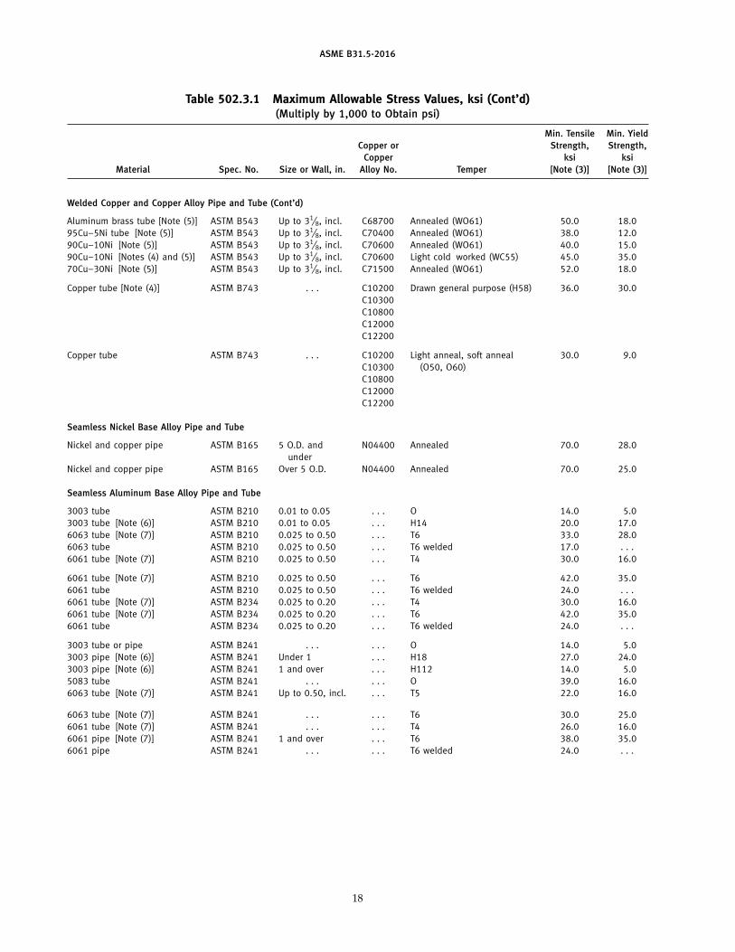
ASME B31.5-2016
Table 502.3.1 Maximum Allowable Stress Values, ksi (Cont’d)(Multiply by 1,000 to Obtain psi)
Min. Tensile Min. YieldCopper or Strength, Strength,
Copper ksi ksiMaterial Spec. No. Size or Wall, in. Alloy No. Temper [Note (3)] [Note (3)]
Welded Copper and Copper Alloy Pipe and Tube (Cont’d)
Aluminum brass tube [Note (5)] ASTM B543 Up to 31⁄8, incl. C68700 Annealed (WO61) 50.0 18.095Cu–5Ni tube [Note (5)] ASTM B543 Up to 31⁄8, incl. C70400 Annealed (WO61) 38.0 12.090Cu–10Ni [Note (5)] ASTM B543 Up to 31⁄8, incl. C70600 Annealed (WO61) 40.0 15.090Cu–10Ni [Notes (4) and (5)] ASTM B543 Up to 31⁄8, incl. C70600 Light cold worked (WC55) 45.0 35.070Cu–30Ni [Note (5)] ASTM B543 Up to 31⁄8, incl. C71500 Annealed (WO61) 52.0 18.0
Copper tube [Note (4)] ASTM B743 . . . C10200 Drawn general purpose (H58) 36.0 30.0C10300C10800C12000C12200
Copper tube ASTM B743 . . . C10200 Light anneal, soft anneal 30.0 9.0C10300 (O50, O60)C10800C12000C12200
Seamless Nickel Base Alloy Pipe and Tube
Nickel and copper pipe ASTM B165 5 O.D. and N04400 Annealed 70.0 28.0under
Nickel and copper pipe ASTM B165 Over 5 O.D. N04400 Annealed 70.0 25.0
Seamless Aluminum Base Alloy Pipe and Tube
3003 tube ASTM B210 0.01 to 0.05 . . . O 14.0 5.03003 tube [Note (6)] ASTM B210 0.01 to 0.05 . . . H14 20.0 17.06063 tube [Note (7)] ASTM B210 0.025 to 0.50 . . . T6 33.0 28.06063 tube ASTM B210 0.025 to 0.50 . . . T6 welded 17.0 . . .6061 tube [Note (7)] ASTM B210 0.025 to 0.50 . . . T4 30.0 16.0
6061 tube [Note (7)] ASTM B210 0.025 to 0.50 . . . T6 42.0 35.06061 tube ASTM B210 0.025 to 0.50 . . . T6 welded 24.0 . . .6061 tube [Note (7)] ASTM B234 0.025 to 0.20 . . . T4 30.0 16.06061 tube [Note (7)] ASTM B234 0.025 to 0.20 . . . T6 42.0 35.06061 tube ASTM B234 0.025 to 0.20 . . . T6 welded 24.0 . . .
3003 tube or pipe ASTM B241 . . . . . . O 14.0 5.03003 pipe [Note (6)] ASTM B241 Under 1 . . . H18 27.0 24.03003 pipe [Note (6)] ASTM B241 1 and over . . . H112 14.0 5.05083 tube ASTM B241 . . . . . . O 39.0 16.06063 tube [Note (7)] ASTM B241 Up to 0.50, incl. . . . T5 22.0 16.0
6063 tube [Note (7)] ASTM B241 . . . . . . T6 30.0 25.06061 tube [Note (7)] ASTM B241 . . . . . . T4 26.0 16.06061 pipe [Note (7)] ASTM B241 1 and over . . . T6 38.0 35.06061 pipe ASTM B241 . . . . . . T6 welded 24.0 . . .
18
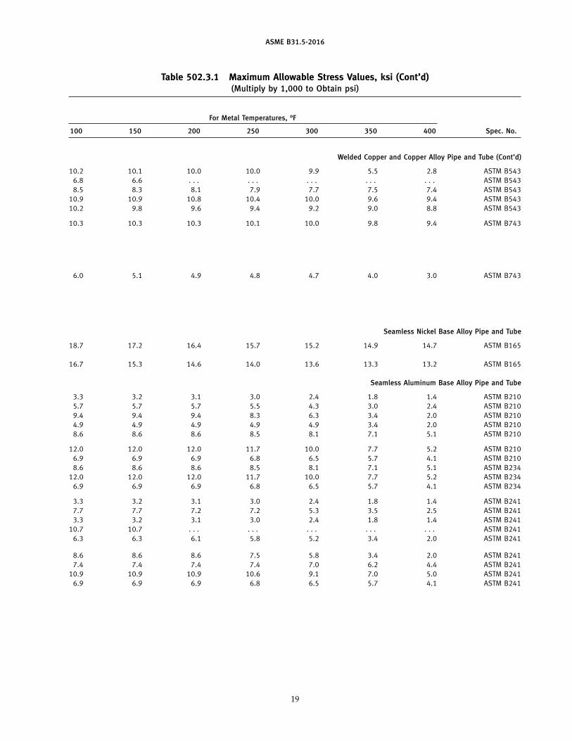
ASME B31.5-2016
Table 502.3.1 Maximum Allowable Stress Values, ksi (Cont’d)(Multiply by 1,000 to Obtain psi)
For Metal Temperatures, °F
100 150 200 250 300 350 400 Spec. No.
Welded Copper and Copper Alloy Pipe and Tube (Cont’d)
10.2 10.1 10.0 10.0 9.9 5.5 2.8 ASTM B5436.8 6.6 . . . . . . . . . . . . . . . ASTM B5438.5 8.3 8.1 7.9 7.7 7.5 7.4 ASTM B543
10.9 10.9 10.8 10.4 10.0 9.6 9.4 ASTM B54310.2 9.8 9.6 9.4 9.2 9.0 8.8 ASTM B543
10.3 10.3 10.3 10.1 10.0 9.8 9.4 ASTM B743
6.0 5.1 4.9 4.8 4.7 4.0 3.0 ASTM B743
Seamless Nickel Base Alloy Pipe and Tube
18.7 17.2 16.4 15.7 15.2 14.9 14.7 ASTM B165
16.7 15.3 14.6 14.0 13.6 13.3 13.2 ASTM B165
Seamless Aluminum Base Alloy Pipe and Tube
3.3 3.2 3.1 3.0 2.4 1.8 1.4 ASTM B2105.7 5.7 5.7 5.5 4.3 3.0 2.4 ASTM B2109.4 9.4 9.4 8.3 6.3 3.4 2.0 ASTM B2104.9 4.9 4.9 4.9 4.9 3.4 2.0 ASTM B2108.6 8.6 8.6 8.5 8.1 7.1 5.1 ASTM B210
12.0 12.0 12.0 11.7 10.0 7.7 5.2 ASTM B2106.9 6.9 6.9 6.8 6.5 5.7 4.1 ASTM B2108.6 8.6 8.6 8.5 8.1 7.1 5.1 ASTM B234
12.0 12.0 12.0 11.7 10.0 7.7 5.2 ASTM B2346.9 6.9 6.9 6.8 6.5 5.7 4.1 ASTM B234
3.3 3.2 3.1 3.0 2.4 1.8 1.4 ASTM B2417.7 7.7 7.2 7.2 5.3 3.5 2.5 ASTM B2413.3 3.2 3.1 3.0 2.4 1.8 1.4 ASTM B241
10.7 10.7 . . . . . . . . . . . . . . . ASTM B2416.3 6.3 6.1 5.8 5.2 3.4 2.0 ASTM B241
8.6 8.6 8.6 7.5 5.8 3.4 2.0 ASTM B2417.4 7.4 7.4 7.4 7.0 6.2 4.4 ASTM B241
10.9 10.9 10.9 10.6 9.1 7.0 5.0 ASTM B2416.9 6.9 6.9 6.8 6.5 5.7 4.1 ASTM B241
19
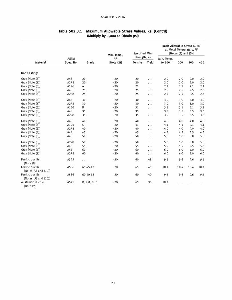
ASME B31.5-2016
Table 502.3.1 Maximum Allowable Stress Values, ksi (Cont’d)(Multiply by 1,000 to Obtain psi)
Basic Allowable Stress S, ksiat Metal Temperature, °F
Specified Min. [Notes (2) and (3)]Min. Temp.,Strength, ksiASTM °F Min. Temp.
Material Spec. No. Grade [Note (2)] Tensile Yield to 100 200 300 400
Iron Castings
Gray [Note (8)] A48 20 −20 20 . . . 2.0 2.0 2.0 2.0Gray [Note (8)] A278 20 −20 20 . . . 2.0 2.0 2.0 2.0Gray [Note (8)] A126 A −20 21 . . . 2.1 2.1 2.1 2.1Gray [Note (8)] A48 25 −20 25 . . . 2.5 2.5 2.5 2.5Gray [Note (8)] A278 25 −20 25 . . . 2.5 2.5 2.5 2.5
Gray [Note (8)] A48 30 −20 30 . . . 3.0 3.0 3.0 3.0Gray [Note (8)] A278 30 −20 30 . . . 3.0 3.0 3.0 3.0Gray [Note (8)] A126 B −20 31 . . . 3.1 3.1 3.1 3.1Gray [Note (8)] A48 35 −20 35 . . . 3.5 3.5 3.5 3.5Gray [Note (8)] A278 35 −20 35 . . . 3.5 3.5 3.5 3.5
Gray [Note (8)] A48 40 −20 40 . . . 4.0 4.0 4.0 4.0Gray [Note (8)] A126 C −20 41 . . . 4.1 4.1 4.1 4.1Gray [Note (8)] A278 40 −20 40 . . . 4.0 4.0 4.0 4.0Gray [Note (8)] A48 45 −20 45 . . . 4.5 4.5 4.5 4.5Gray [Note (8)] A48 50 −20 50 . . . 5.0 5.0 5.0 5.0
Gray [Note (8)] A278 50 −20 50 . . . 5.0 5.0 5.0 5.0Gray [Note (8)] A48 55 −20 55 . . . 5.5 5.5 5.5 5.5Gray [Note (8)] A48 60 −20 60 . . . 6.0 6.0 6.0 6.0Gray [Note (8)] A278 60 −20 60 . . . 6.0 6.0 6.0 6.0
Ferritic ductile A395 . . . −20 60 48 9.6 9.6 9.6 9.6[Note (9)]
Ferritic ductile A536 65-45-12 −20 65 45 10.4 10.4 10.4 10.4[Notes (9) and (10)]
Ferritic ductile A536 60-40-18 −20 60 40 9.6 9.6 9.6 9.6[Notes (9) and (10)]
Austenitic ductile A571 D, 2M, Cl. 1 −20 65 30 10.4 . . . . . . . . .[Note (9)]
20
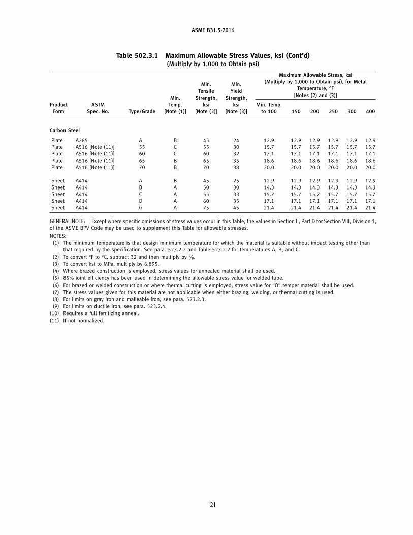
ASME B31.5-2016
Table 502.3.1 Maximum Allowable Stress Values, ksi (Cont’d)(Multiply by 1,000 to Obtain psi)
Maximum Allowable Stress, ksi(Multiply by 1,000 to Obtain psi), for MetalMin. Min.
Temperature, °FTensile Yield[Notes (2) and (3)]Min. Strength, Strength,
Product ASTM Temp. ksi ksi Min. Temp.Form Spec. No. Type/Grade [Note (1)] [Note (3)] [Note (3)] to 100 150 200 250 300 400
Carbon Steel
Plate A285 A B 45 24 12.9 12.9 12.9 12.9 12.9 12.9Plate A516 [Note (11)] 55 C 55 30 15.7 15.7 15.7 15.7 15.7 15.7Plate A516 [Note (11)] 60 C 60 32 17.1 17.1 17.1 17.1 17.1 17.1Plate A516 [Note (11)] 65 B 65 35 18.6 18.6 18.6 18.6 18.6 18.6Plate A516 [Note (11)] 70 B 70 38 20.0 20.0 20.0 20.0 20.0 20.0
Sheet A414 A B 45 25 12.9 12.9 12.9 12.9 12.9 12.9Sheet A414 B A 50 30 14.3 14.3 14.3 14.3 14.3 14.3Sheet A414 C A 55 33 15.7 15.7 15.7 15.7 15.7 15.7Sheet A414 D A 60 35 17.1 17.1 17.1 17.1 17.1 17.1Sheet A414 G A 75 45 21.4 21.4 21.4 21.4 21.4 21.4
GENERAL NOTE: Except where specific omissions of stress values occur in this Table, the values in Section II, Part D for Section VIII, Division 1,of the ASME BPV Code may be used to supplement this Table for allowable stresses.
NOTES:(1) The minimum temperature is that design minimum temperature for which the material is suitable without impact testing other than
that required by the specification. See para. 523.2.2 and Table 523.2.2 for temperatures A, B, and C.(2) To convert °F to °C, subtract 32 and then multiply by 5⁄9.(3) To convert ksi to MPa, multiply by 6.895.(4) Where brazed construction is employed, stress values for annealed material shall be used.(5) 85% joint efficiency has been used in determining the allowable stress value for welded tube.(6) For brazed or welded construction or where thermal cutting is employed, stress value for “O” temper material shall be used.(7) The stress values given for this material are not applicable when either brazing, welding, or thermal cutting is used.(8) For limits on gray iron and malleable iron, see para. 523.2.3.(9) For limits on ductile iron, see para. 523.2.4.
(10) Requires a full ferritizing anneal.(11) If not normalized.
21
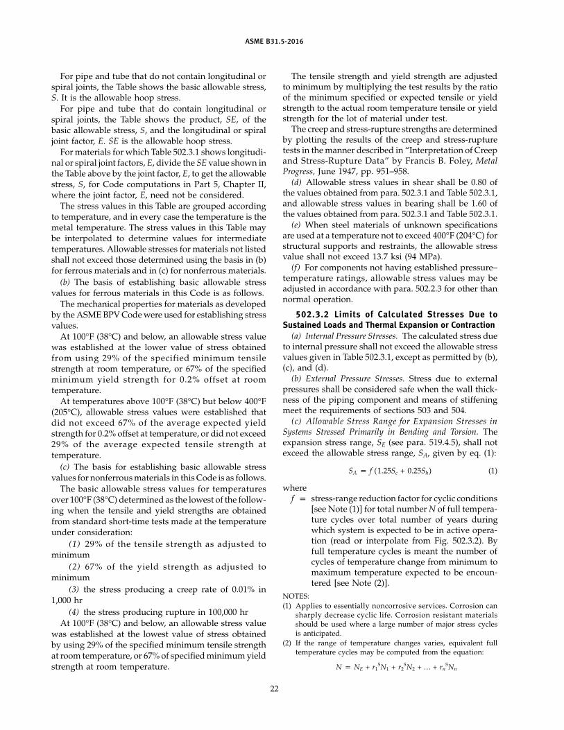
ASME B31.5-2016
For pipe and tube that do not contain longitudinal orspiral joints, the Table shows the basic allowable stress,S. It is the allowable hoop stress.
For pipe and tube that do contain longitudinal orspiral joints, the Table shows the product, SE, of thebasic allowable stress, S, and the longitudinal or spiraljoint factor, E. SE is the allowable hoop stress.
For materials for which Table 502.3.1 shows longitudi-nal or spiral joint factors, E, divide the SE value shown inthe Table above by the joint factor, E, to get the allowablestress, S, for Code computations in Part 5, Chapter II,where the joint factor, E, need not be considered.
The stress values in this Table are grouped accordingto temperature, and in every case the temperature is themetal temperature. The stress values in this Table maybe interpolated to determine values for intermediatetemperatures. Allowable stresses for materials not listedshall not exceed those determined using the basis in (b)for ferrous materials and in (c) for nonferrous materials.
(b) The basis of establishing basic allowable stressvalues for ferrous materials in this Code is as follows.
The mechanical properties for materials as developedby the ASME BPV Code were used for establishing stressvalues.
At 100°F (38°C) and below, an allowable stress valuewas established at the lower value of stress obtainedfrom using 29% of the specified minimum tensilestrength at room temperature, or 67% of the specifiedminimum yield strength for 0.2% offset at roomtemperature.
At temperatures above 100°F (38°C) but below 400°F(205°C), allowable stress values were established thatdid not exceed 67% of the average expected yieldstrength for 0.2% offset at temperature, or did not exceed29% of the average expected tensile strength attemperature.
(c) The basis for establishing basic allowable stressvalues for nonferrous materials in this Code is as follows.
The basic allowable stress values for temperaturesover 100°F (38°C) determined as the lowest of the follow-ing when the tensile and yield strengths are obtainedfrom standard short-time tests made at the temperatureunder consideration:
(1) 29% of the tensile strength as adjusted tominimum
(2) 67% of the yield strength as adjusted tominimum
(3) the stress producing a creep rate of 0.01% in1,000 hr
(4) the stress producing rupture in 100,000 hrAt 100°F (38°C) and below, an allowable stress value
was established at the lowest value of stress obtainedby using 29% of the specified minimum tensile strengthat room temperature, or 67% of specified minimum yieldstrength at room temperature.
22
The tensile strength and yield strength are adjustedto minimum by multiplying the test results by the ratioof the minimum specified or expected tensile or yieldstrength to the actual room temperature tensile or yieldstrength for the lot of material under test.
The creep and stress-rupture strengths are determinedby plotting the results of the creep and stress-rupturetests in the manner described in “Interpretation of Creepand Stress-Rupture Data” by Francis B. Foley, MetalProgress, June 1947, pp. 951–958.
(d) Allowable stress values in shear shall be 0.80 ofthe values obtained from para. 502.3.1 and Table 502.3.1,and allowable stress values in bearing shall be 1.60 ofthe values obtained from para. 502.3.1 and Table 502.3.1.
(e) When steel materials of unknown specificationsare used at a temperature not to exceed 400°F (204°C) forstructural supports and restraints, the allowable stressvalue shall not exceed 13.7 ksi (94 MPa).
(f) For components not having established pressure–temperature ratings, allowable stress values may beadjusted in accordance with para. 502.2.3 for other thannormal operation.
502.3.2 Limits of Calculated Stresses Due toSustained Loads and Thermal Expansion or Contraction
(a) Internal Pressure Stresses. The calculated stress dueto internal pressure shall not exceed the allowable stressvalues given in Table 502.3.1, except as permitted by (b),(c), and (d).
(b) External Pressure Stresses. Stress due to externalpressures shall be considered safe when the wall thick-ness of the piping component and means of stiffeningmeet the requirements of sections 503 and 504.
(c) Allowable Stress Range for Expansion Stresses inSystems Stressed Primarily in Bending and Torsion. Theexpansion stress range, SE (see para. 519.4.5), shall notexceed the allowable stress range, SA, given by eq. (1):
SA p f (1.25Sc + 0.25Sh) (1)
wheref p stress-range reduction factor for cyclic conditions
[see Note (1)] for total number N of full tempera-ture cycles over total number of years duringwhich system is expected to be in active opera-tion (read or interpolate from Fig. 502.3.2). Byfull temperature cycles is meant the number ofcycles of temperature change from minimum tomaximum temperature expected to be encoun-tered [see Note (2)].
NOTES:(1) Applies to essentially noncorrosive services. Corrosion can
sharply decrease cyclic life. Corrosion resistant materialsshould be used where a large number of major stress cyclesis anticipated.
(2) If the range of temperature changes varies, equivalent fulltemperature cycles may be computed from the equation:
N p NE + r15N1 + r2
5N2 + … + rn5Nn
ASME B31.5-2016
Fig. 502.3.2 Stress Range Reduction Factors
NOTE:(1) Assuming 365-day-per-year operation.
whereNE p number of cycles of full temperature
change, �TE, for which expansion stress,SE, has been calculated
N1, N2, . . ., Nn p number of cycles of less temperaturechange �T1, �T2, . . ., �Tn
r1, r2, . . ., rn p �T1/�TE, �T2/�TE, . . ., �Tn/�TE
p ratio of any lesser temperature cycle tothat for which SE has been calculated
SA p maximum allowable stress range due to ther-mal expansion and contraction, ksi (MPa)
Sc p basic material allowable stress at minimum(cold) normal temperature, ksi (MPa) (use S,not SE from para. 502.3.1 and Table 502.3.1)
Sh p basic material allowable stress at maximum(hot) normal temperature, ksi (MPa) (use S, notSE from para. 502.3.1 and Table 502.3.1)
NOTE: Does not include abnormal conditions, such as exposureto fires.
(d) The sum of the longitudinal stresses (in the cor-roded condition) due to pressure, weight, and other sus-tained external loading shall not exceed Sh. Where thesum of these stresses is less than Sh, the differencebetween Sh and this sum may be added to the term inparentheses in eq. (1).
23
In calculating the longitudinal pressure stress, con-sider the internal pressure as acting only on the areaestablished by the internal diameter.
502.3.3 Limits of Calculated Stresses Due toOccasional Loads
(a) Operation. The sum of the longitudinal stressesproduced by pressure, live and dead loads, and thoseproduced by occasional loads, such as wind or earth-quake, may not exceed 1.33 times the allowable stressvalues given in Table 502.3.1. It is not necessary to con-sider wind and earthquake as occurring concurrently.
(b) Test. Stresses due to test conditions are not subjectto the limitations of para. 502.3 of this Code. It is notnecessary to consider other occasional loads, such aswind and earthquake, as occurring concurrently withthe live, dead, and test loads existing at the time of test.
502.4 Allowances
502.4.1 Corrosion and Erosion. When corrosion orerosion is expected, an increase in wall thickness of thecomponents over that dictated by other design require-ments shall be provided, consistent with the expectedlife of the particular piping involved.
ASME B31.5-2016
502.4.2 Threading and Grooving. See definition forc in para. 504.1.1(b).
502.4.3 Mechanical Strength. When necessary toprevent damage, collapse, or buckling due to superim-posed loads from supports, backfill, or other causes,the pipe wall thickness shall be increased, or, if this isimpractical or would cause excessive local stresses, thefactors that would contribute to damage of the pipingshall be compensated for by other design methods.
Section 502 pertains to ratings, stress values, stresscriteria, design allowances, and minimum design values,and formulates the permissible variations to these fac-tors used in the design of piping.
PART 2DESIGN OF PIPING COMPONENTS
503 CRITERIA FOR DESIGN OF PIPINGCOMPONENTS
The design of piping components, considering theeffects of pressure, and providing for mechanical, corro-sion, and erosion allowances, shall be in accordance withsection 504. In addition, the designs must be checked foradequacy of mechanical strength under other applicableloadings as given in section 501.
504 PRESSURE DESIGN OF PIPING COMPONENTS
504.1 Straight Pipe
504.1.1 General(a) The required wall thickness of straight sections of
pipe shall be determined in accordance with eq. (2).(Also, see section 503.)
tm p t + c (2)
(b) The notations described below are used in theequations for the pressure design of straight pipe.
c p for internal pressure, the sum, in. (mm), of themechanical allowances (thread depth, groovedepth, and manufacturer’s minus tolerance)plus corrosion and erosion allowances (seepara. 502.4.1). For threaded components, thenominal thread depth (dimension h ofASME B1.20.1, or equivalent) shall apply. Formachined surfaces or grooves, where the toler-ance is not specified, the tolerance shall beassumed to be 1⁄64 in. (0.5 mm) in addition tothe specified depth of the cut.
24
p for external pressure, the sum, in. (mm), of cor-rosion and erosion allowances plus manufac-turer’s minus tolerance (see para. 502.4.1)
Do p outside diameter of pipe, in. (mm)d p inside diameter of pipe, in. (mm), excluding
metal required for corrosion or erosion allow-ance, manufacturer’s minus tolerance, and anyallowance required for the depth of internalthreads or grooves
P p internal design pressure (see para. 501.2.2), psi(kPa), or external design pressure (seepara. 501.2.3), psi (kPa)
S p applicable allowable hoop stress in accordancewith para. 502.3.1 and Table 502.3.1, psi (kPa)
t p pressure design wall thickness, in. (mm), ascalculated from eqs. (3a) and (3b) for internalpressure, or in accordance with the proceduresgiven in para. 504.1.3 for external pressure
tm p minimum required wall thickness, in. (mm),satisfying requirements for design pressure andmechanical, corrosion, and erosion allowances
y p coefficient for materials indicated: for ductilenonferrous materials, use y p 0.4 (see Note);for ferritic steels, use y p 0.4 (see Note); foraustenitic steels, use y p 0.4 (see Note). Forcast iron, use y p 0.0.
NOTE: If Do/t is in the range of 4–6, use y p d/(d + Do) for ductilematerials.
504.1.2 Straight Pipe Under Internal Pressure. Formetallic pipe with diameter–thickness ratios Do/t > 4,the internal pressure design wall thickness, t, shall becalculated using eq. (3a) or (3b).
t pPDo
2 (S + Py)(3a)
or
t pPd
2 (S + Py − P)(3b)
where
P p2St
Do − 2yt
NOTE: The following simpler alternative equations, which givesomewhat greater wall thickness, may be employed:
t pPDo
2 S
or
t pPd
2 (S − P)
where
P p2StDo
ASME B31.5-2016
504.1.3 Straight Pipe Under External Pressure. Todetermine wall thickness and stiffening requirementsfor straight pipe under external pressure, the procedureoutlined in the BPV Code, Section VIII, Division 1, UG-28through UG-30 shall be followed, using as the designlength, L, the running centerline length between anytwo sections stiffened in accordance with UG-29. As anexception, for pipe with Do /t < 10, the value of S to beused in determining Pa2 shall be the lesser of the follow-ing values for pipe material at design temperature:
(a) 1.5 times the stress value from Table 502.3.1 of thisCode.
(b) 0.9 times the yield strength tabulated in Section II,Part D, Table Y-1 for materials listed therein. (The symbolDo in Section VIII of the ASME BPV Code is equivalentto Do in this Code.)
504.2 Curved Segments of Pipe
504.2.1 Pipe Bends. Pipe after bending shall con-form to the following:
(a) The minimum thickness after bending shall notbe less than as required for straight pipe in accordancewith para. 504.1.
(b) The difference between maximum and minimumdiameters for pipe bends subjected to internal pressureshould not exceed 8% of the nominal outside diameterof the pipe.
(c) The difference between maximum and minimumdiameters for pipe bends subjected to external pressureshould not be greater than 8% of the nominal outsidediameter of the pipe.
(d) Bends made with greater flattening than indicatedabove shall meet the requirements of para. 504.7.
(e) Bends for use on heat transfer components such asU-bends (return bends) shall be designed in accordancewith the requirements of para. 504.7.
504.2.2 Elbows. Elbows manufactured in accor-dance with the standards listed in Table 526.1 shall beconsidered suitable for use at the pressure–temperatureratings specified by such standards, and in the case ofstandards under which elbows are made to a nominalpipe thickness, the elbows shall be considered suitablefor use with pipe of the same nominal thickness unlessotherwise stated by the fittings standard. Commerciallymanufactured elbows not made in accordance with thestandards listed in Table 526.1 shall meet the require-ments of para. 504.7.
504.3 Intersections
504.3.1 Branch Connections(a) This paragraph gives rules governing the design
of branch connections to sustain internal and externalpressure in cases where the angle between the axes ofthe branch and of the run is between 45 deg and 90 deg.
Branch connections in which the smaller anglebetween the axes of the branch and the run is less than
25
45 deg impose special design and fabrication problems;the rules given for angles greater than 45 deg may beused as a guide, but sufficient additional strength mustbe provided to assure safe and satisfactory service, andthese branch connections shall be designed to meet therequirement of para. 504.7.
(b) Branch connections in piping may be made by theuse of one of the following:
(1) fittings (tees, laterals, crosses, and multipleopening headers, qualified as fully reinforced in accor-dance with para. 504.7)
(2) welding outlet fittings, such as forged nozzles,couplings [maximum NPS 3 (DN 75)], or adaptors orsimilar items having butt welding, socket welding,threaded, or flanged ends for attachment of the branchpipe, such welding outlet fittings being attached to themain pipe by welding
(3) by attaching the branch pipe directly to the runpipe by welding (acceptable methods of making weldedpipe-to-pipe branch connections are contained inpara. 527.3.5) or by threading
(c) Right angle branch connections may be made byattaching the branch pipe directly to the run pipe bysocket welding provided
(1) the nominal size of the branch does not exceedNPS 2 (DN 50) or one-fourth the nominal size of therun, whichever is lesser.
(2) the depth of the socket in the run is at least3⁄8 in. (10 mm) deep with a minimum shoulder of 1⁄16 in.(1.5 mm) between the bottom of the socket and the insidediameter of the run pipe. [Weld metal may be depositedon the run pipe to provide the required socket depth andto provide any reinforcement required by (f) and (g).]
(3) the size of the fillet weld is not less than 1.25times the nominal branch wall thickness.
(d) Right angle branch connections may be made bythreading the branch pipe directly to the run pipeprovided
(1) the nominal size of the branch does not exceedNPS 2 (DN 50) or one-fourth the nominal size of therun, whichever is lesser.
(2) minimum thread engagement is six full threadsfor NPS 1⁄2 (DN 15) and NPS 3⁄4 (DN 20) branches, sevenfor NPS 1 (DN 25) and NPS 11⁄2 (DN 40) branches, andeight for NPS 2 (DN 50) branches. [Weld metal may bedeposited on the run to provide sufficient thickness forthe required thread engagement and to provide any rein-forcement required by (f) and (g). In interpreting (f) and(g) for connections threaded directly into the run pipe,no part of the branch pipe may be counted in calculatingthe reinforcement area, and the value of d1 shall be takenas the nominal outside diameter of the branch pipe.]
(e) A pipe having a branch connection is weakenedby the opening that must be made in it, and unless thewall thickness of the pipe is sufficiently in excess ofthat required to sustain the pressure, it is necessary to
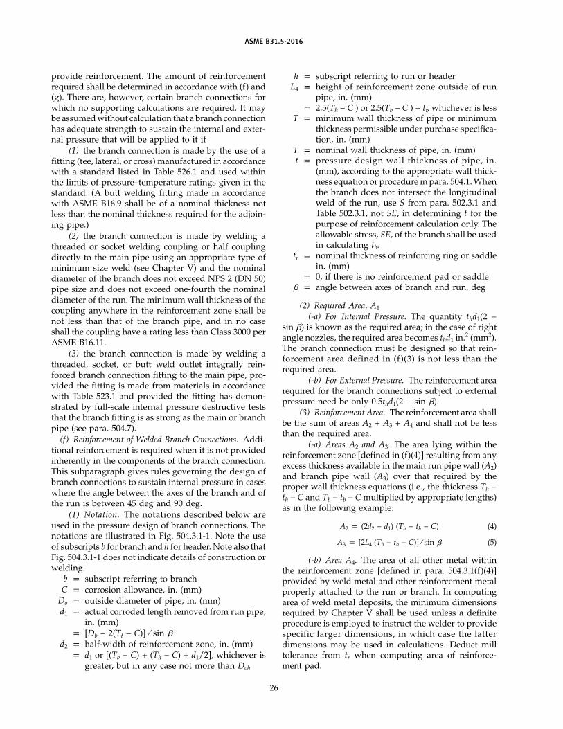
ASME B31.5-2016
provide reinforcement. The amount of reinforcementrequired shall be determined in accordance with (f) and(g). There are, however, certain branch connections forwhich no supporting calculations are required. It maybe assumed without calculation that a branch connectionhas adequate strength to sustain the internal and exter-nal pressure that will be applied to it if
(1) the branch connection is made by the use of afitting (tee, lateral, or cross) manufactured in accordancewith a standard listed in Table 526.1 and used withinthe limits of pressure–temperature ratings given in thestandard. (A butt welding fitting made in accordancewith ASME B16.9 shall be of a nominal thickness notless than the nominal thickness required for the adjoin-ing pipe.)
(2) the branch connection is made by welding athreaded or socket welding coupling or half couplingdirectly to the main pipe using an appropriate type ofminimum size weld (see Chapter V) and the nominaldiameter of the branch does not exceed NPS 2 (DN 50)pipe size and does not exceed one-fourth the nominaldiameter of the run. The minimum wall thickness of thecoupling anywhere in the reinforcement zone shall benot less than that of the branch pipe, and in no caseshall the coupling have a rating less than Class 3000 perASME B16.11.
(3) the branch connection is made by welding athreaded, socket, or butt weld outlet integrally rein-forced branch connection fitting to the main pipe, pro-vided the fitting is made from materials in accordancewith Table 523.1 and provided the fitting has demon-strated by full-scale internal pressure destructive teststhat the branch fitting is as strong as the main or branchpipe (see para. 504.7).
(f) Reinforcement of Welded Branch Connections. Addi-tional reinforcement is required when it is not providedinherently in the components of the branch connection.This subparagraph gives rules governing the design ofbranch connections to sustain internal pressure in caseswhere the angle between the axes of the branch and ofthe run is between 45 deg and 90 deg.
(1) Notation. The notations described below areused in the pressure design of branch connections. Thenotations are illustrated in Fig. 504.3.1-1. Note the useof subscripts b for branch and h for header. Note also thatFig. 504.3.1-1 does not indicate details of construction orwelding.
b p subscript referring to branchC p corrosion allowance, in. (mm)
Do p outside diameter of pipe, in. (mm)d1 p actual corroded length removed from run pipe,
in. (mm)p [Db − 2(Tt − C)] ⁄ sin �
d2 p half-width of reinforcement zone, in. (mm)p d1 or [(Tb − C) + (Th − C) + d1/2], whichever is
greater, but in any case not more than Doh
26
h p subscript referring to run or headerL4 p height of reinforcement zone outside of run
pipe, in. (mm)p 2.5(Th − C ) or 2.5(Tb − C ) + tr, whichever is less
T p minimum wall thickness of pipe or minimumthickness permissible under purchase specifica-tion, in. (mm)
T–
p nominal wall thickness of pipe, in. (mm)t p pressure design wall thickness of pipe, in.
(mm), according to the appropriate wall thick-ness equation or procedure in para. 504.1. Whenthe branch does not intersect the longitudinalweld of the run, use S from para. 502.3.1 andTable 502.3.1, not SE, in determining t for thepurpose of reinforcement calculation only. Theallowable stress, SE, of the branch shall be usedin calculating tb.
tr p nominal thickness of reinforcing ring or saddlein. (mm)
p 0, if there is no reinforcement pad or saddle� p angle between axes of branch and run, deg
(2) Required Area, A1
(-a) For Internal Pressure. The quantity thd1(2 −sin �) is known as the required area; in the case of rightangle nozzles, the required area becomes thd1 in.2 (mm2).The branch connection must be designed so that rein-forcement area defined in (f)(3) is not less than therequired area.
(-b) For External Pressure. The reinforcement arearequired for the branch connections subject to externalpressure need be only 0.5thd1(2 − sin �).
(3) Reinforcement Area. The reinforcement area shallbe the sum of areas A2 + A3 + A4 and shall not be lessthan the required area.
(-a) Areas A2 and A3. The area lying within thereinforcement zone [defined in (f)(4)] resulting from anyexcess thickness available in the main run pipe wall (A2)and branch pipe wall (A3) over that required by theproper wall thickness equations (i.e., the thickness Th −th − C and Tb − tb − C multiplied by appropriate lengths)as in the following example:
A2 p (2d2 − d1) (Th − th − C) (4)
A3 p [2L4 (Tb − tb − C)] ⁄ sin � (5)
(-b) Area A4. The area of all other metal withinthe reinforcement zone [defined in para. 504.3.1(f)(4)]provided by weld metal and other reinforcement metalproperly attached to the run or branch. In computingarea of weld metal deposits, the minimum dimensionsrequired by Chapter V shall be used unless a definiteprocedure is employed to instruct the welder to providespecific larger dimensions, in which case the latterdimensions may be used in calculations. Deduct milltolerance from tr when computing area of reinforce-ment pad.
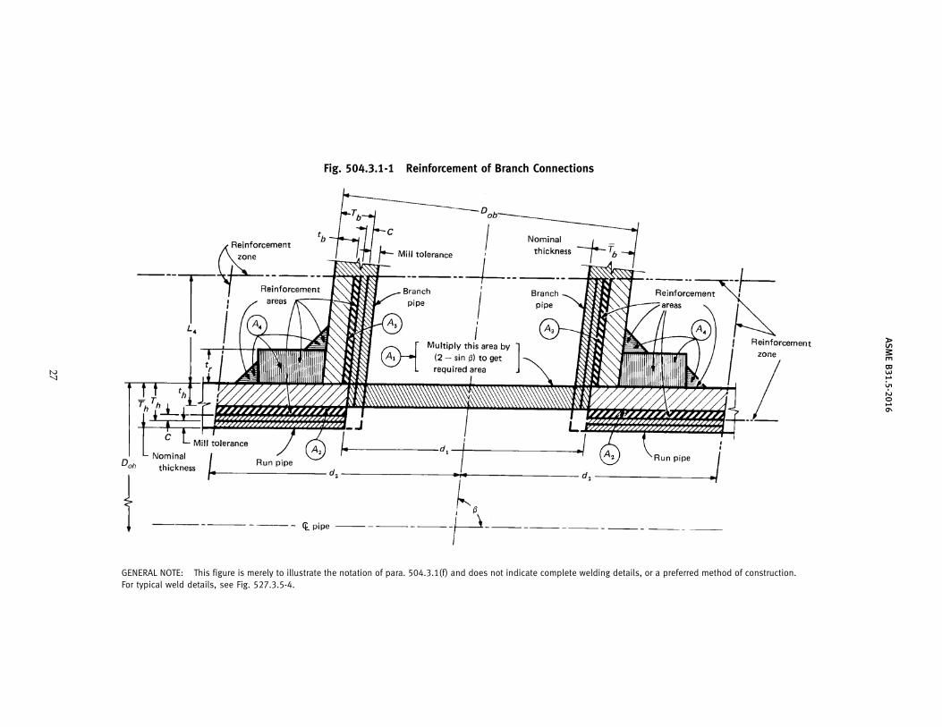
AS
ME
B31.5-2016
Fig. 504.3.1-1 Reinforcement of Branch Connections
GENERAL NOTE: This figure is merely to illustrate the notation of para. 504.3.1(f) and does not indicate complete welding details, or a preferred method of construction.For typical weld details, see Fig. 527.3.5-4.
27
ASME B31.5-2016
Portions of the reinforcement area may be composedof materials other than those of the main run pipe, butif the allowable stress of these materials (see para. 502.3.1and Table 502.3.1) is less than that for the main run pipe,the calculated area for such portions must be reducedin the ratio of the allowable stress values before beingcredited to the reinforcement area. No additional creditshall be taken for materials having higher allowablestress values than for the main run pipe.
(4) Reinforcement Zone. The reinforcement zone isa parallelogram whose length shall extend a distance,d2, on each side of the centerline of the branch pipe andwhose width shall start at the actual corroded insidesurface of the main run pipe and extend to a distance,L4, from the outside surface of the main pipe measuredperpendicular to this outside surface.
(5) Reinforcement of Multiple Openings. When anytwo or more adjacent openings are so closely spacedthat their reinforcement zones overlap, the two or moreopenings shall be reinforced in accordance with (f)(2)with a combined reinforcement that has a strength equalto the combined strength of the reinforcement thatwould be required for the separate openings. No portionof the cross section shall be considered as applying tomore than one opening, or be evaluated more than oncein a combined area.
When more than two adjacent openings are to beprovided with a combined reinforcement, the minimumdistance between centers of any two of these openingsshould preferably be at least 1.5 times their averagediameter, and the area of reinforcement between themshall be at least equal to 50% of the total required forthese two openings.
(6) Rings and Saddles. Additional reinforcementprovided in the form of rings or saddles shall not beappreciably narrower in the transverse direction thanin the longitudinal direction.
(g) Extruded Outlet Headers(1) The above principles of reinforcement are essen-
tially applicable to extruded outlet headers. An extrudedoutlet header is defined as a header in which the outletis extruded using a die (or dies) that controls the radiiof the extrusion. The extruded lip at the outlet has aheight above the surface of the run that is equal toor greater than the radius of curvature of the externalcontoured portion of the outlet (i.e., hx ≥ rx). [See (g)(3)for notation and Fig. 504.3.1-2.]
(2) When the design meets the limitations of geom-etry outlined below, the rules herein established arevalid. These rules cover minimum requirements and aredesigned to assure satisfactory performance of extrudedoutlet headers subjected to pressure. These rules applyonly to cases where the axis of the outlet intersects andis perpendicular to the axis of the run. These rules donot apply to any nozzle in which additional nonintegralmaterial is applied in the form of rings, pads, or saddles.
28
(3) Notations. The notations used herein are illus-trated in Fig. 504.3.1-2. Note the use of subscript x forextruded outlet. Refer to (f) for notations not listed here.
d2 p half-width of reinforcement zone, in. (mm)(equal to dx)
dx p the corroded design inside diameter of theextruded outlet, in. (mm), at the level of theoutside surface of the run
hx p height of the extruded outlet, in. (mm). Thismust be equal to or greater than rx.
L5 p height of reinforcement zone, in. (mm)p 0.7�Dob Tx
rx p radius of curvature of external contoured por-tion of outlet measured in the plane containingthe axis of the run and branch, in. (mm). Thisis subject to the following limitations:
(a) Minimum Radius. This dimension shallnot be less than 0.05Dob except that on branchdiameters larger than NPS 30 (DN 750) it neednot exceed 1.50 in. (38 mm).
(b) Maximum Radius. For outlet pipe sizesNPS 8 (DN 200) and larger, this dimension shallnot exceed 0.10Dob + 0.50 in. (12.7 mm) Foroutlet pipe sizes less than NPS 8 (DN 200) thisdimension shall not be greater than 1.25 in.(32 mm).
(c) When the external contour contains morethan one radius, the radius of any arc sector ofapproximately 45 deg shall meet the require-ments for maximum and minimum radii.
(d) Machining shall not be employed in orderto meet the above requirements.
Tx p corroded finished thickness of extruded outletat a height equal to rx above the outside surfaceof the run, in. (mm)
(4) Required Area. The required area is defined asA1 p Kthdx where K shall be taken as follows:
(a) For Dob/Doh greater than 0.60, K p 1.00.(b) For Dob/Doh greater than 0.15 and not
exceeding 0.60,
K p 0.6 + 2⁄3 Dob/Doh (6)
(c) For Dob/Doh equal to or less than 0.15, K p0.70.
The design must meet the criteria that the reinforce-ment area defined in (g)(5) is not less than the requiredarea A1.
(5) Reinforcement Area. The reinforcement area shallbe the sum of areas A2 + A3 + A4 as defined below.
(-a) Area A2. The area lying within the reinforce-ment zone resulting from any excess thickness availablein the run wall.
A2 p dx(Th − th) (7)
ASME B31.5-2016
Fig. 504.3.1-2 Extruded Outlet Header Notation
GENERAL NOTE: This figure is merely to illustrate the notations of para. 504.3.1(g) and does not indicate complete welding details, or apreferred method of construction.
NOTES:(1) Illustration to show method of establishing TX when the taper encroaches on the crotch radius.(2) Illustration is drawn for condition where K p 1.00.(3) Illustration is drawn for condition where K p 1.00 and dx < (Dob − 2Tb).
29
ASME B31.5-2016
(-b) Area A3. The area lying within the reinforce-ment zone resulting from any excess thickness availablein the branch pipe wall.
A3 p 2L5(Tb − tb) (8)
(-c) Area A4. The area lying within the reinforce-ment zone resulting from any excess thickness availablein the extruded outlet lip.
A4 p 2rx(Tx − tb) (9)
(6) Reinforcement of Multiple Openings. The rules of(f)(5) shall be followed except that the required area andreinforcement area shall be as given in (g).
(7) In addition to the above, the manufacturer shallbe responsible for establishing and marking, on theheader containing extruded outlets, the design pressureand temperature and this Code section. The manufactur-er’s name or trademark shall be marked on the header.
(h) Mechanically Formed Tee Connections in CopperMaterials (Types K, L, M)
(1) These mechanically formed connections shallbe perpendicular to the axis of the run tube (header).They shall be formed by drilling a pilot hole and drawingout the tube surface to form a collar having a height ofnot less than 3 times the thickness of the branch wall.The collaring device shall be such as to assure properfit up of the joint.
(2) The inner branch tube end shall conform to theshape of the inner curve of the run tube. Insertion ofthe branch tube shall be controlled to assure alignmentwith specified depth into the collar without extendinginto the flow stream so as to provide internal reinforce-ment to the collar as illustrated in Fig. 504.3.1-3.
(3) Branches can be formed up to the run tube size.Manufacturing procedures shall be in accordance withtool manufacturer’s recommendations.
(4) These types of connections may not be used inother than Group A1 refrigerant service.
(5) All joints shall be brazed in accordance withparas. 528.1 and 528.2.
(i) Other Designs. Components to which design rulesgiven in (c) and (d) are not applicable shall meet therequirements of para. 504.7.
(j) The requirements of the preceding subparagraphsare designed to assure satisfactory performance of abranch connection subjected only to pressure. However,in addition, external forces and moments are usuallyapplied to a branch connection by such agencies as ther-mal expansion and contraction, by dead weight of pip-ing, valves, and fittings; covering and contents; and byearth settlement. Special consideration shall be given tothe design of a branch connection to withstand theseforces and moments.
Where the ratio of branch diameter to run diameteris large or where repetitive stresses may be imposed
30
on the connection due to vibration, pulsating pressure,temperature cycling, etc., it is recommended that thedesign be rather conservative and that consideration begiven to the use of tee fittings or complete encirclementtypes of reinforcement.
Use of ribs, gussets, and clamps is permissible tostiffen the branch connection, but their areas cannotbe counted as contributing to the reinforcement areadefined in (d)(3). Consideration should be given to stressarising from a temperature gradient between the pipingand gussets during a sudden change in temperature ofthe fluid in the piping.
It is not practicable to give definite rules for designto accommodate the effects mentioned in this subpara-graph. The purpose is to call them to the attention ofthe engineer so that from experience and judgment hemay adequately provide for them.
Attention is especially directed to the design of smallbranches out of large and relatively heavy runs. Ade-quate flexibility must be provided in the smaller line toaccommodate thermal expansion and other movementsof the larger line.
504.3.2 Openings in Closures(a) The rules of this paragraph are intended to apply
to openings in closures in which the size of the openingis not greater than 50% of the inside diameter of theclosure (as defined in para. 504.4). Larger openingsshould be designed as reducers, or in the case of flatclosures, the closure shall be designed as a flange inaccordance with para. 504.5.
(b) A closure is weakened by an opening and unlessthe thickness of the closure is sufficiently in excess of thatrequired to sustain pressure, it is necessary to providereinforcement. The need for reinforcement and amountof reinforcement required shall be determined in accor-dance with the subparagraphs below except that it shallbe considered that the opening has adequate reinforce-ment if subparas. (1) through (3) apply:
(1) The outlet connection is made by welding athreaded or socket welding coupling or half-couplingdirectly to the closure (using an appropriate weld asgiven in Fig. 527.3.5-4 for branch connections).
(2) The nominal diameter of the outlet pipe doesnot exceed NPS 2 (DN 50) and does not exceed 25% ofthe nominal diameter of the closure.
(3) The minimum wall thickness of the couplinganywhere in the reinforcement zone shall not be lessthan that of the branch pipe and in no case shall acoupling have a rating less than Class 3000 perASME B16.11.
(c) Reinforcement shall be provided for openings inclosures in amount and distribution such that the arearequirements for distribution are satisfied for all planespassing through the center of the opening and normalto the surface of the closure.
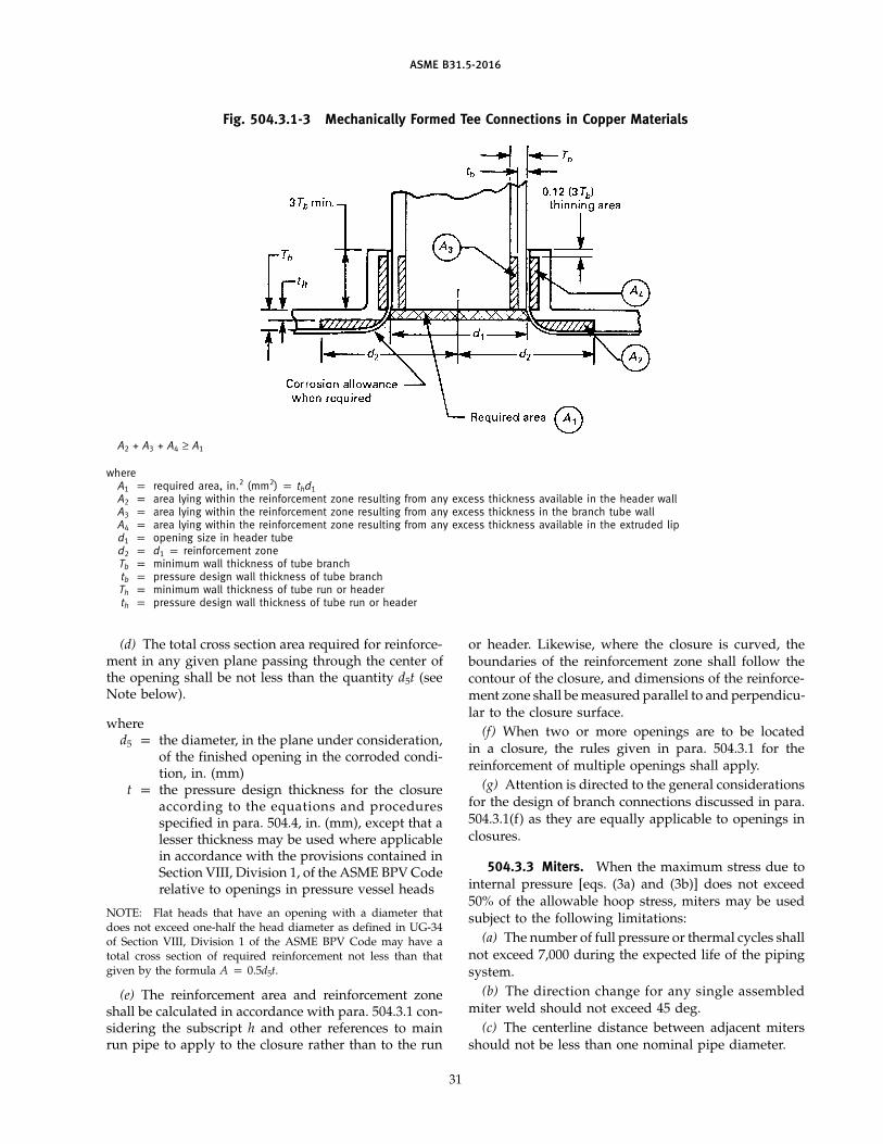
ASME B31.5-2016
Fig. 504.3.1-3 Mechanically Formed Tee Connections in Copper Materials
A2 + A3 + A4 ≥ A1
whereA1 p required area, in.2 (mm2) p thd1A2 p area lying within the reinforcement zone resulting from any excess thickness available in the header wallA3 p area lying within the reinforcement zone resulting from any excess thickness in the branch tube wallA4 p area lying within the reinforcement zone resulting from any excess thickness available in the extruded lipd1 p opening size in header tubed2 p d1 p reinforcement zoneTb p minimum wall thickness of tube branchtb p pressure design wall thickness of tube branchTh p minimum wall thickness of tube run or headerth p pressure design wall thickness of tube run or header
(d) The total cross section area required for reinforce-ment in any given plane passing through the center ofthe opening shall be not less than the quantity d5t (seeNote below).
whered5 p the diameter, in the plane under consideration,
of the finished opening in the corroded condi-tion, in. (mm)
t p the pressure design thickness for the closureaccording to the equations and proceduresspecified in para. 504.4, in. (mm), except that alesser thickness may be used where applicablein accordance with the provisions contained inSection VIII, Division 1, of the ASME BPV Coderelative to openings in pressure vessel heads
NOTE: Flat heads that have an opening with a diameter thatdoes not exceed one-half the head diameter as defined in UG-34of Section VIII, Division 1 of the ASME BPV Code may have atotal cross section of required reinforcement not less than thatgiven by the formula A p 0.5d5t.
(e) The reinforcement area and reinforcement zoneshall be calculated in accordance with para. 504.3.1 con-sidering the subscript h and other references to mainrun pipe to apply to the closure rather than to the run
31
or header. Likewise, where the closure is curved, theboundaries of the reinforcement zone shall follow thecontour of the closure, and dimensions of the reinforce-ment zone shall be measured parallel to and perpendicu-lar to the closure surface.
(f) When two or more openings are to be locatedin a closure, the rules given in para. 504.3.1 for thereinforcement of multiple openings shall apply.
(g) Attention is directed to the general considerationsfor the design of branch connections discussed in para.504.3.1(f) as they are equally applicable to openings inclosures.
504.3.3 Miters. When the maximum stress due tointernal pressure [eqs. (3a) and (3b)] does not exceed50% of the allowable hoop stress, miters may be usedsubject to the following limitations:
(a) The number of full pressure or thermal cycles shallnot exceed 7,000 during the expected life of the pipingsystem.
(b) The direction change for any single assembledmiter weld should not exceed 45 deg.
(c) The centerline distance between adjacent mitersshould not be less than one nominal pipe diameter.
ASME B31.5-2016
(d) Complete penetration welds shall be used in join-ing miter segments.
(e) Miter joints with greater directional changes andcloser centerline distances shall conform to para. 504.7.Deflections caused by misalignments up to 3 deg arenot considered miters.
504.3.4 Attachments. External and internal attach-ments to piping shall be designed so they will not causeflattening of the pipe, excessive localized bendingstresses, or harmful thermal gradients in the pipe wall.It is important that such attachments be designed tominimize stress concentrations in applications where thenumber of stress cycles, due either to pressure or thermaleffect, is relatively large for the expected life of theequipment.
504.4 Closures
504.4.1 General(a) The required thickness of closures, considering
pressure and mechanical, corrosion, and erosion allow-ances, shall be determined in accordance with eq. (10).
tm p t + c (10)
The minimum thickness for the closure selected, con-sidering the manufacturer’s minus tolerances, shall notbe less than tm.
Closure fittings manufactured in accordance with thestandards listed in Table 526.1 shall be considered suit-able for use at the pressure–temperature ratings speci-fied by such standards, and in the case of standardsunder which closure fittings are made to a nominal pipethickness, the closure fittings shall be considered suit-able for use with pipe of the same nominal thickness.Commercially manufactured closures not made in accor-dance with the standards listed in Table 526.1 and forwhich design rules are not given in this paragraph(para. 504.4) shall meet the requirements of para. 504.7.
(b) The notations described below are used fordetermining the pressure design of closures.
c p the sum of the mechanical allowances (threaddepth, groove depth, manufacturer’s minus tol-erances) plus corrosion and erosion allowances,in. (mm) (see para. 502.4)
P p internal design pressure (see para. 501.2.2), psi,or external design pressure (see para. 501.2.3),psi (kPa)
S p applicable allowable stress (the value of S orproduct SE) in accordance with para. 502.3.1and Table 502.3.1, ksi (MPa)
t p pressure design thickness as calculated for thegiven closure shape and direction of pressureloading from the appropriate equations andprocedures in Section VIII, Division 1, of theASME BPV Code, in. (mm). (Symbols P and S,used in these equations, shall have the mean-ings described in this paragraph instead of
32
those given in the ASME BPV Code. All othersymbols shall be as defined in the ASME BPVCode.)
tm p minimum required closure thickness satisfyingrequirements for pressure and mechanical, cor-rosion and erosion allowances, in. (mm)
504.4.2 Flat Plate Closures. The minimum requiredthickness, tm, for a flat plate closure (shown inFig. 527.3.6-1) shall be determined in accordance witheq. (11).
tm p d �CP/S + c (11)
whereC p 0.33 [tr /(tn − c)] but not less than 0.20c p as defined in para. 504.4.1(b)d p inside diameter of pipe, in. (mm)P p as defined in para. 504.4.1(b)S p as defined in para. 504.4.1(b)T–
p nominal pipe wall thickness, in. (mm)T–
p p nominal thickness of platetr p required wall thickness of pipe [equal to tm of
eq. (2)], in. (mm)
504.5 Pressure Design of Flanges and Blanks
504.5.1 General(a) Flanges manufactured in accordance with the
standards listed in Table 526.1 shall be considered suit-able for use at the pressure–temperature ratings speci-fied by such standards. Flanges not made in accordancewith the standards listed in Table 526.1 shall be designedin accordance with Section VIII, Division 1, of the ASMEBPV Code except that the requirements for fabrication,assembly, inspection, and testing, and the pressure andtemperature limits for materials of this Code shall gov-ern. Also, certain notations used in the ASME BPV Code,namely, P, Sa, Sb, and Sf, shall have the meaningsdescribed in this paragraph instead of those given inthe ASME BPV Code. All other notations shall be asdefined in the ASME BPV Code.
P p internal design gage pressure (see para.501.2.2), psi (kPa). (Flanges subject to externalpressure should be designed for an internalpressure equal to the external design pressure.)
Sa p bolt design stress, ksi (MPa), at 100°F (38°C)(from Section VIII, Division 1, of the ASMEBPV Code)
Sb p bolt design stress, ksi (MPa), at design tempera-ture (from Section VIII, Division 1, of the ASMEBPV Code)
Sf p allowable stress, ksi (MPa), for flange materialor pipe (from para. 502.3.1 and Table 502.3.1)
(b) The flange design rules presented in (a) are notapplicable to designs employing flat faced flanges usedwith full-face gaskets that extend beyond the bolts, usu-ally to the outside diameter of the flange. The forces
ASME B31.5-2016
and reactions in such a joint are very different from thosefound on ring-gasketed joints, and the flange should bedesigned to meet the requirements of para. 504.7.
504.5.2 Blind Flanges. Blind flanges manufacturedin accordance with the standards listed in Table 526.1shall be considered suitable for use at the pressure–temperature ratings specified by such standards.
(a) The required thickness of blind flanges not manu-factured in accordance with standards in Table 526.1shall be calculated in accordance with eq. (12), consider-ing pressure and mechanical, corrosion, and erosionallowances. The minimum thickness for the blind flangeselected, considering manufacturer’s minus tolerance,shall be not less than tm.
tm p t + c (12)
(b) The notations described below are used for thedetermining of pressure design of blind flanges:
c p sum of the mechanical, corrosion, and erosionallowances, in. (mm)
P p internal design pressure (see para. 501.2.2), psi(kPa), or external design pressure (seepara. 501.2.3), psi (kPa)
S p applicable allowable stress in accordance withpara. 502.3.1 and Table 502.3.1, ksi (MPa)
t p pressure design thickness, in. (mm), as calcu-lated for the given closure shape and directionof pressure loading from the appropriate equa-tions and procedures in Section VIII, Division 1,of the ASME BPV Code. (Symbols P and S,used in these equations, shall be considered tohave the meanings described in this paragraphinstead of those given in the ASME BPV Code.All other symbols shall be as defined in theASME BPV Code.)
tm p minimum required blind flange thickness, sat-isfying requirements for pressure and mechani-cal, corrosion, and erosion allowances, in. (mm)
504.5.3 Blanks(a) The pressure design thickness of permanent
blanks (see Fig. 504.5.3) shall be calculated in accordancewith eqs. (12) and (13).
t p dg � 3P16S
(13)
wheredg p inside diameter of gasket for raised or flat
(plain) face flanges, or the gasket pitch diameterfor retained gasketed flanges, in. (mm)
P p internal design pressure (see para. 501.2.2), psi(kPa), or external design pressure (seepara. 501.2.3), psi (kPa)
S p applicable allowable stress in accordance withpara. 502.3.1 and Table 502.3.1, ksi (MPa)
33
(b) Blanks to be used for test purposes only shall bedesigned in accordance with eq. (13), except that P shallbe at least equal to the test pressure and S may be asgreat as 95% of the specified minimum yield strengthof the blank material. (This applies only if the test fluidis incompressible.)
504.6 Headers
Headers used on heat transfer components shall bedesigned in accordance with para. 504.3 and/or shallmeet the requirements of para. 504.7.
504.7 Design of Other Pressure-ContainingComponents
Other pressure-containing components manufacturedin accordance with the standards listed in Table 526.1shall be considered suitable for use at the pressure–temperature ratings specified by such standards.Pressure-containing components not covered by thestandards listed in Table 526.1 and for which designformulas or procedures are not given in this paragraph(section 504) may be used where they have been provensatisfactory by successful performance under compara-ble service conditions. (Where such satisfactory serviceexperience exists, interpolation may be made to othersized components with a geometrically similar shape.)In the absence of such service experience, the pressuredesign shall be based on an analysis consistent withthe general design philosophy embodied in this Codesection and substantiated by at least one of thefollowing:
(a) proof tests (as described in UG-101 of Section VIII,Division 1, of the ASME BPV Code)
(b) experimental stress analysis(c) for heat transfer components, proof test a sample
at three times the design pressure of the component
PART 3DESIGN APPLICATION OF PIPING COMPONENTS
SELECTION AND LIMITATIONS
505 PIPE
505.1 General
Pipe, tubes, and other materials conforming to thestandards and specifications listed in Tables 502.3.1 and526.1 shall be used within the limitations of temperatureand stress given in para. 502.3.1 and Table 502.3.1 andwithin the additional limitations contained in this Code.
505.1.1 Additional Limitations for Carbon SteelPipe. The wall thickness for refrigerant pipe sizes NPS 6(DN 150) and smaller shall be no less than Schedule 40(ASME B36.10M), and for liquid refrigerants inGroups A2, A3, B2, and B3, pipe sizes smaller than NPS 2(DN 50) shall be no less than Schedule 80.
ASTM A53 Type F and API 5L A25 PSL 1 furnacebutt welded pipe is permitted in service at temperatures
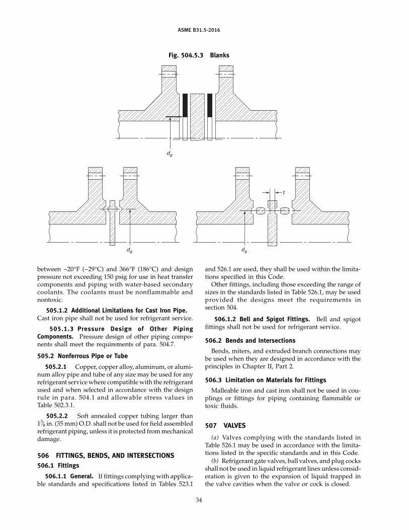
ASME B31.5-2016
Fig. 504.5.3 Blanks
dg
dg dg
t
between −20°F (−29°C) and 366°F (186°C) and designpressure not exceeding 150 psig for use in heat transfercomponents and piping with water-based secondarycoolants. The coolants must be nonflammable andnontoxic.
505.1.2 Additional Limitations for Cast Iron Pipe.Cast iron pipe shall not be used for refrigerant service.
505.1.3 Pressure Design of Other PipingComponents. Pressure design of other piping compo-nents shall meet the requirements of para. 504.7.
505.2 Nonferrous Pipe or Tube
505.2.1 Copper, copper alloy, aluminum, or alumi-num alloy pipe and tube of any size may be used for anyrefrigerant service where compatible with the refrigerantused and when selected in accordance with the designrule in para. 504.1 and allowable stress values inTable 502.3.1.
505.2.2 Soft annealed copper tubing larger than13⁄8 in. (35 mm) O.D. shall not be used for field assembledrefrigerant piping, unless it is protected from mechanicaldamage.
506 FITTINGS, BENDS, AND INTERSECTIONS506.1 Fittings
506.1.1 General. If fittings complying with applica-ble standards and specifications listed in Tables 523.1
34
and 526.1 are used, they shall be used within the limita-tions specified in this Code.
Other fittings, including those exceeding the range ofsizes in the standards listed in Table 526.1, may be usedprovided the designs meet the requirements insection 504.
506.1.2 Bell and Spigot Fittings. Bell and spigotfittings shall not be used for refrigerant service.
506.2 Bends and Intersections
Bends, miters, and extruded branch connections maybe used when they are designed in accordance with theprinciples in Chapter II, Part 2.
506.3 Limitation on Materials for Fittings
Malleable iron and cast iron shall not be used in cou-plings or fittings for piping containing flammable ortoxic fluids.
507 VALVES
(a) Valves complying with the standards listed inTable 526.1 may be used in accordance with the limita-tions listed in the specific standards and in this Code.
(b) Refrigerant gate valves, ball valves, and plug cocksshall not be used in liquid refrigerant lines unless consid-eration is given to the expansion of liquid trapped inthe valve cavities when the valve or cock is closed.
(16)
(16)
ASME B31.5-2016
508 FLANGES, BLANKS, FLANGE FACINGS,GASKETS, AND BOLTING
508.1 Flanges
508.1.1 General. If flanges complying with applica-ble standards and specifications listed in Tables 523.1and 526.1 are used, they shall be used within the limita-tions specified in this Code.
Other flanges, including those exceeding the range ofsizes in the standards listed in Table 526.1, may be usedprovided the designs meet the requirements ofsection 504.
508.1.2 Screwed Flanges. Screwed flanges are sub-ject to restrictions on threaded joints established insection 514.
508.2 Blanks
Blanks shall conform to design requirements inpara. 504.5.3.
508.3 Flange Facings
Flange facings complying with standards listed inTable 526.1 are suitable for use under this Code. Otherspecial facings may be used provided they meet therequirements of para. 504.7.
Class 150 steel flanges may be bolted to cast ironvalves, fittings, or other cast iron piping componentshaving Class 125 flanges.
Class 300 steel flanges may be bolted to cast ironvalves, fittings, or other cast iron piping componentshaving Class 250 flanges.
Bolt strength should be limited when flange facing(such as raised face) or gasket design creates a momentload on the flanges (see para. 508.5.2).
508.4 Gaskets
Selection of suitable material for a given service is theresponsibility of the user, and subject to any applicablecode or jurisdictional regulation. The material selectedshall be compatible with the fluid and suitable for thepressure–temperature conditions and shall meet therequirements of ASME B16.20 or ASME B16.21.
508.5 Bolting
508.5.1 General. If bolts, nuts, and washers com-plying with applicable standards and specificationslisted in Tables 523.1 and 526.1 are used, they shall beused within the limitations specified in this Code andshall also be subject to the requirements of Chapter IIIand paras. 508.3 and 508.5.2(a) and (b).
508.5.2 Bolting for Cast Iron Flanges. The use ofcast iron flanges (paired with another cast iron or aforged steel flange) requires consideration of the typeof facing and gasket when selecting the appropriatefastener. A joint type that will place the flanges in a
35
moment load (such as raised face flange or a ring-typegasket) should utilize a fastener having a tensile strengthno higher than that of ASTM A307 Grade B material.Flanged joints that do not place a moment load on theflange (such as flat-face flanges with a full-face gasket)may utilize fasteners with higher tensile strength, asappropriate. Consideration must also be given to gasketseating stress when selecting fastener material.
PART 4SELECTION AND LIMITATIONS OF PIPING JOINTS
510 PIPING JOINTS
510.1 General
The type of piping joint used shall be suitable for thepressure–temperature conditions, and shall be selectedgiving consideration to joint tightness and mechanicalstrength under the service conditions (including thermalexpansion and vibration) and to the nature of the fluidhandled with respect to corrosion, erosion, flammability,and toxicity.
The following limitations are in addition to applicablerequirements in other portions of this Code Section.
511 WELDED JOINTS
511.1 General
Welded joints may be used with any materials forwhich it is possible to qualify welding procedures, weld-ers, and welding operators in conformance withChapter V.
511.2 Butt Welds
Butt welds shall be made in accordance with the appli-cable requirements of Chapter V and section 500. Whenbacking rings are used in services where their use willresult in severe corrosion or erosion, the backing ringshould be removed and the internal joint groundsmooth. In such services where it is impractical toremove the backing ring, consideration shall be given towelding the joint without backing rings, or consumableinserts may be used.
511.3 Socket Welds
511.3.1 Socket welds shall be made in accordancewith the applicable requirements of Chapter V andsection 500. Dimensions of socket welding piping jointsshall conform to ASME B16.5 for flanges andASME B16.11 for fittings, and the weld dimensions shallbe not less than the minimum dimensions shown inFigs. 527.3.3-2 and 527.3.3-3.
511.3.2 Socket welded connections inserteddirectly into the wall of the run pipe shall be in accor-dance with requirements of para. 504.3.1(c).
(16)
ASME B31.5-2016
511.3.3 Drains and bypasses may be attached toa fitting or valve by socket welding, provided the socketdepth, bore diameter, and shoulder thickness conformto the requirements of ASME B16.5.
511.4 Fillet Welds
Fillet welds shall be made in accordance with theapplicable requirements of Chapter V and section 500.Fillet welds shall not have dimensions less than theminimum dimensions shown in Figs. 527.3.3-2, 527.3.3-3,and 527.3.5-4.
511.5 Seal Welds
Seal welds may be used to avoid joint leakage; how-ever, they shall not be considered as contributing anystrength to the joint (see also para. 527.3.4).
512 FLANGED JOINTS
Flanged joints shall meet the requirements ofsection 508.
513 EXPANDED JOINTS
Expanded joints may be used where experience ortests have demonstrated that the joint is suitable for theconditions and where adequate provisions are made inthe design to prevent separations of the joints.
514 THREADED JOINTS
(a) Threaded joints may be used within the limitsstated in paras. 514(b) through (f).
(b) When used, all pipe threads shall be taper pipethreads where the tightness of joint depends upon theseating of the thread. Tapered pipe threads shall conformto the requirements of ASME B1.20.1. Straight threadson pipe joints that depend upon a seating surface otherthan the thread are allowed within the limitations ofsection 518 if the thread root is no deeper than a standardpipe thread.
(c) Threaded joints larger than NPS 4 (DN 100) shouldnot be used in refrigerant service.
(d) Threaded joints larger than NPS 2 (DN 50) shallnot be used for Groups A2 and B2, and Class 3refrigerants.
(e) Threaded joints larger than NPS 6 (DN 150) shouldnot be used for salt brines.
(f) External threaded components may be used inaccordance with Table 514 and its Notes.
515 FLARED, FLARELESS, AND COMPRESSIONJOINTS
515.1 Selection and Application
In selecting and applying flared, flareless, and com-pression type tube fittings, the designer shall consider
36
Table 514 Minimum Thickness ofExternal Threaded Components
Notch Minimum WallSize RangeSensitive Thickness
Material DN NPS [Note (1)]
Yes [Note (2)] ≤ 40 ≤ 11⁄2 Sch. 8050 2 Sch. 4065–150 21⁄2–6 Sch. 40
No [Note (3)] ≤ 50 ≤ 2 Sch. 40S65–150 21⁄2–6 Sch. 40S
GENERAL NOTE: Use the greater of para. 504.1.1, paras. 514(b)through (e), or this Table.
NOTES:(1) Nominal wall thickness is listed for carbon steel in ASME
B36.10M and for Sch. 40S in ASME B36.19M.(2) For example, carbon steel.(3) For example, austenitic stainless steel.
the adverse effects on the joints of such factors as assem-bly and disassembly, cyclic loading, vibration, shock,thermal expansion and contraction, and the problem offrost growth between the tube and fitting.
515.2 Piping Joints With Applicable Standards
Piping joints using flared, flareless, or compressionfittings may be used within the limitations of applicablestandards or specifications listed in Table 526.1 and thefollowing requirements:
(a) Fittings and their joints shall be suitable for thetubing with which they are to be used with considerationto minimum tubing wall thickness and method of assem-bly recommended by the manufacturer.
(b) Fittings shall not be used in services that exceedthe manufacturer’s maximum pressure–temperaturerecommendations.
515.3 Piping Joints Without Applicable Standards
For piping joints using flared, flareless, or compres-sion fittings for which there are no applicable standardsor specifications listed in Table 526.1, the engineer shalldetermine that the type of fitting selected is adequateand safe for the design conditions and that it meets therequirements of paras. 515.2(a) and (b) and the followingrequirements:
(a) The pressure design shall meet the requirementsof para. 504.7.
(b) A suitable quantity of the type and size of fittingto be used shall meet successful performance tests todetermine the safety of the joint under simulated serviceconditions. When vibration, fatigue, cyclic conditions,low temperature, thermal expansion, hydraulic shock,or frost growth are anticipated, the applicable conditionsshall be incorporated in the test.
(16)
(16)
ASME B31.5-2016
517 BRAZED AND SOLDERED JOINTS
Brazed and soldered socket type joints may be usedwith the following limitations for the attachment ofvalves, fittings, and flanges to nonferrous pipe andtubing:
(a) Soldered joints shall not be used for piping con-taining other than Group A1 refrigerants or any othertoxic or flammable fluid.
(b) Bores and depths of sockets of brazed and solderedfittings shall conform to the dimensions in ASME B16.18or ASME B16.22. Depths of sockets for brazed fittingsonly may conform to MIL-F-1183J.
(c) Brazed socket type joints may be used providedit is determined that the fittings are adequate and safefor the design conditions in accordance with the require-ments listed in section 515 for flared and flareless fittings.
(d) The piping systems should be kept free of fluxand other foreign materials.
(e) Solder joints shall not be used for temperatures inexcess of those given in ASME B16.22.
(f) The design shall take into account that braze meth-ods may reduce the strength of the heated base materialto that of the annealed state.
518 SLEEVE COUPLED AND OTHER NOVEL ORPATENTED JOINTS
Coupling type, mechanical gland type, and other pat-ented or novel type joints may be used provided ade-quate provisions are made to prevent separation of thejoints and provided a prototype joint has been subjectedto performance tests to determine the safety of the jointunder simulated service conditions. When vibration,fatigue, cyclic conditions, low temperature, thermalexpansion, or hydraulic shock are anticipated, the appli-cable conditions shall be incorporated in the tests.
PART 5EXPANSION, FLEXIBILITY, STRUCTURAL
ATTACHMENTS, SUPPORTS, AND RESTRAINTS
519 EXPANSION AND FLEXIBILITY
519.1 General
The following clauses define the objectives of pipingflexibility analysis and alternative ways in which thesecan be realized.
519.1.1 Objectives. Piping systems shall bedesigned to have sufficient flexibility to prevent thermalexpansion from causing either of the following:
(a) failure of piping or anchors from overstress oroverstrain
(b) leakage at joints(c) detrimental distortion of connected equipment
(pumps, turbines, or valves) resulting from excessivethrusts and moments
37
519.1.2 Expansion Strains. Expansion strains maybe taken up in two ways, either primarily by bendingor torsion, in which case only the extreme fibers at thecritical location are stressed to the limit, or by axialcompression and tension, in which case the entire cross-sectional area over the entire length is substantiallyequally stressed.
(a) Bending or torsional flexibility may be providedby the use of bends, loops, or offsets; or by swivel joints,ball joints, corrugated pipe, or expansion joints of thebellows type permitting angular movement. Suitableanchors, ties, or other devices shall be provided as neces-sary to resist end forces from fluid pressure, frictional,or other resistance to joint movement and other causes.
(b) Axial flexibility may be provided by expansionjoints of the slip-joint or bellows types. Pipe runningfrom anchors to the joints must be guided where neces-sary to keep the pipe from bowing because of end forcesoriginating in the joint from fluid pressure, friction, anddeformation of the bellows. Anchors must be adequatefor these forces plus the force arising from friction inthe guides. For design and selection of expansion jointsof the bellows type, reference to the standards of theExpansion Joint Manufacturers Association isrecommended.
519.2 Concepts
Concepts peculiar to piping flexibility analysis andrequiring special consideration are explained in the fol-lowing paragraphs.
519.2.1 Stress Range. As contrasted with stressesfrom sustained loads (such as internal pressure orweight), stresses caused by thermal expansion in sys-tems stressed primarily in bending and torsion are per-mitted to attain sufficient initial magnitude to causelocal yielding or creep. The attendant relaxation orreduction of stress in the hot condition leads to thecreation of a stress reversal when the component returnsto the cold condition. This phenomenon is designatedas self-springing of the line and is similar in effect tocold springing. The amount of self-springing dependson the initial magnitude of the expansion stress, thematerial, the temperature, and the elapsed time. Whilethe expansion stress in the hot condition tends to dimin-ish with time, the arithmetic sum of the expansionstresses in the hot and cold conditions during any onecycle remains substantially constant. This sum, referredto as the stress range, is the determining factor in thethermal design of piping.
519.2.2 Expansion Range. In computing the stressrange, the full thermal expansion range from the mini-mum to maximum metal temperature normallyexpected during installation and operation shall be used,whether the piping is cold sprung or not. Linear or

ASME B31.5-2016
angular movements of the equipment to which the pip-ing is attached shall be included. For values of the unitthermal expansion range, refer to para. 519.3.1.
Where substantial anchor or terminal movements areanticipated as a result of tidal changes (unloading dockpiping) or wind sway (piping attached to slendertowers), these effects shall be considered analogous toterminal movements caused by thermal expansion.
519.2.3 Cold Spring. Cold spring is recognized asbeneficial in that it serves to balance hot and cold stresseswithout drawing on the ductility of the material, forwhich reason it is recommended in particular for materi-als of relatively low ductility. In addition, it helps assureminimum departure from as-erected hanger settings.Inasmuch as the life of a system under cyclic conditionsdepends primarily on the stress range rather than thestress level at any one time, no credit for cold spring isgiven for stress range calculations. In calculating endthrusts and moments where actual reactions at any onetime rather than their range are considered significant,cold spring is credited. (See para. 519.4.6.)
519.2.4 Local Overstrain. All the commonly usedmethods of piping flexibility analysis assume elasticbehavior of the entire piping system. This assumption issufficiently accurate for systems where plastic strainingoccurs at many points or over relatively wide regions,but fails to reflect the actual strain distribution in unbal-anced systems where only a small portion of the pipingundergoes plastic strain, or where, in piping operatingin the creep range, the strain distribution is very uneven.In these cases, the weaker or higher stressed portionswill be subjected to strain concentrations due to elasticfollowup of the stiffer or lower stressed portions. Unbal-ance can be produced
(a) by use of small pipe runs in series with larger orstiffer pipe with the small lines relatively highly stressed
(b) by local reduction in size or cross section, or localuse of a weaker material
(c) in a system of uniform size, by use of a line config-uration for which the neutral axis (actually, the wrenchaxis) is situated close to the major portion of the linewith only a very small portion projecting away from itabsorbing most of the expansion strain
Conditions of this type should preferably be avoided,particularly where materials of relatively low ductilityare used; if unavoidable, they should be mitigated bythe judicious application of cold spring.
519.3 Properties
The following paragraphs deal with materials andgeometric properties of pipe and piping componentsand the manner in which they are to be used in pipingflexibility analysis.
519.3.1 Unit Thermal Expansion Range. The ther-mal expansion range, e, in./100 ft (mm/m), shall be
38
determined from Table 519.3.1 as the algebraic differencebetween the unit expansion shown for the maximumnormal operating metal temperature and that for theminimum normal operating metal temperature. Formaterials not included in this Table, reference shall bemade to authoritative source data, such as publicationsof the National Institute of Standards and Technology.
519.3.2 Moduli of Elasticity. The cold and hot mod-uli of elasticity, Ec and Eh, respectively, shall be takenfrom Table 519.3.2 for the minimum and maximum nor-mal operating metal temperatures in Table 519.3.2. Formaterials not included in these Tables, reference shallbe made to authoritative source data, such as publica-tions of the National Institute of Standards andTechnology.
519.3.3 Poisson’s Ratio. Poisson’s ratio is the ratioof the unit deformation at right angles to the directionof the load to the unit deformation in the direction ofthe load, and may be taken as 0.3 at all temperaturesfor all metals. However, more-accurate data may be usedif available.
519.3.4 Allowable Expansion Stress Range. Theallowable basic expansion stress range, SA, and permissi-ble additive stresses shall be as specified in paras.502.3.2(c) and (d) for systems primarily stressed in bend-ing or torsion.
519.3.5 Dimensions. Nominal dimensions of pipeand fittings, and cross-sectional areas, moments of iner-tia, and section moduli based thereon shall be used inflexibility calculations, including the permissible addi-tive stresses.
519.3.6 Flexibility and Stress IntensificationFactors. Calculations shall take into account stressintensification factors found to exist in components otherthan plain straight pipe. Credit may be taken for theextra flexibility of such components. In the absence ofmore directly applicable data, the flexibility and stressintensification factors shown in Table 519.3.6 may beused. For piping components or attachments (such asvalves, strainers, anchor rings, or bands) not covered inthe Table, suitable stress intensification factors may beassumed by comparison of their significant geometrywith that of the components shown.
519.4 Analysis for Bending Flexibility
The following paragraphs establish under what cir-cumstances and in what manner piping flexibility analy-ses are to be made where the system primarily derivesits flexibility from bending or torsional strains.
519.4.1 Calculations/Tests. Formal calculations ormodel tests shall be required only where reasonabledoubt exists as to the adequate flexibility of a system.
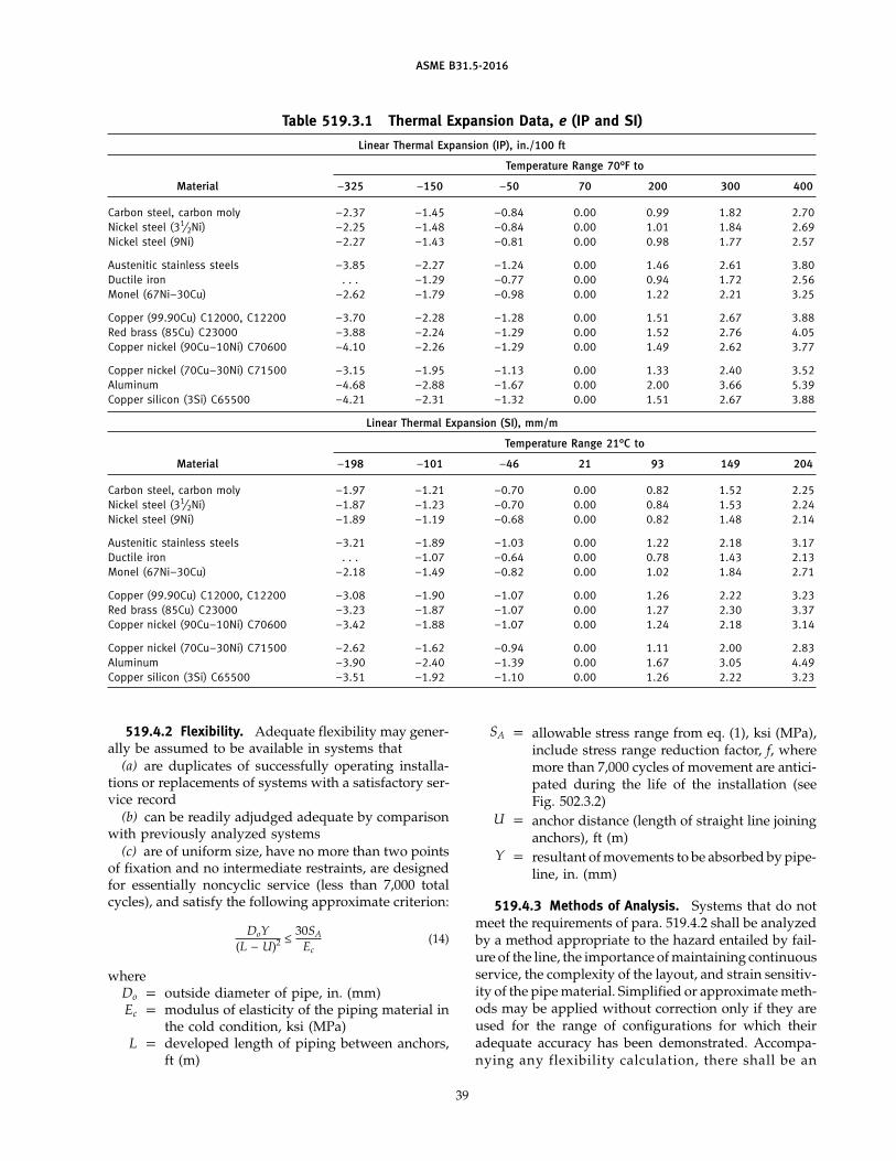
ASME B31.5-2016
Table 519.3.1 Thermal Expansion Data, e (IP and SI)
Linear Thermal Expansion (IP), in./100 ft
Temperature Range 70°F to
Material −325 −150 −50 70 200 300 400
Carbon steel, carbon moly −2.37 −1.45 −0.84 0.00 0.99 1.82 2.70Nickel steel (31⁄2Ni) −2.25 −1.48 −0.84 0.00 1.01 1.84 2.69Nickel steel (9Ni) −2.27 −1.43 −0.81 0.00 0.98 1.77 2.57
Austenitic stainless steels −3.85 −2.27 −1.24 0.00 1.46 2.61 3.80Ductile iron . . . −1.29 −0.77 0.00 0.94 1.72 2.56Monel (67Ni–30Cu) −2.62 −1.79 −0.98 0.00 1.22 2.21 3.25
Copper (99.90Cu) C12000, C12200 −3.70 −2.28 −1.28 0.00 1.51 2.67 3.88Red brass (85Cu) C23000 −3.88 −2.24 −1.29 0.00 1.52 2.76 4.05Copper nickel (90Cu–10Ni) C70600 −4.10 −2.26 −1.29 0.00 1.49 2.62 3.77
Copper nickel (70Cu–30Ni) C71500 −3.15 −1.95 −1.13 0.00 1.33 2.40 3.52Aluminum −4.68 −2.88 −1.67 0.00 2.00 3.66 5.39Copper silicon (3Si) C65500 −4.21 −2.31 −1.32 0.00 1.51 2.67 3.88
Linear Thermal Expansion (SI), mm/m
Temperature Range 21°C to
Material −198 −101 −46 21 93 149 204
Carbon steel, carbon moly −1.97 −1.21 −0.70 0.00 0.82 1.52 2.25Nickel steel (31⁄2Ni) −1.87 −1.23 −0.70 0.00 0.84 1.53 2.24Nickel steel (9Ni) −1.89 −1.19 −0.68 0.00 0.82 1.48 2.14
Austenitic stainless steels −3.21 −1.89 −1.03 0.00 1.22 2.18 3.17Ductile iron . . . −1.07 −0.64 0.00 0.78 1.43 2.13Monel (67Ni–30Cu) −2.18 −1.49 −0.82 0.00 1.02 1.84 2.71
Copper (99.90Cu) C12000, C12200 −3.08 −1.90 −1.07 0.00 1.26 2.22 3.23Red brass (85Cu) C23000 −3.23 −1.87 −1.07 0.00 1.27 2.30 3.37Copper nickel (90Cu–10Ni) C70600 −3.42 −1.88 −1.07 0.00 1.24 2.18 3.14
Copper nickel (70Cu–30Ni) C71500 −2.62 −1.62 −0.94 0.00 1.11 2.00 2.83Aluminum −3.90 −2.40 −1.39 0.00 1.67 3.05 4.49Copper silicon (3Si) C65500 −3.51 −1.92 −1.10 0.00 1.26 2.22 3.23
519.4.2 Flexibility. Adequate flexibility may gener-ally be assumed to be available in systems that
(a) are duplicates of successfully operating installa-tions or replacements of systems with a satisfactory ser-vice record
(b) can be readily adjudged adequate by comparisonwith previously analyzed systems
(c) are of uniform size, have no more than two pointsof fixation and no intermediate restraints, are designedfor essentially noncyclic service (less than 7,000 totalcycles), and satisfy the following approximate criterion:
DoY(L − U)2 ≤
30SA
Ec(14)
whereDo p outside diameter of pipe, in. (mm)Ec p modulus of elasticity of the piping material in
the cold condition, ksi (MPa)L p developed length of piping between anchors,
ft (m)
39
SA p allowable stress range from eq. (1), ksi (MPa),include stress range reduction factor, f, wheremore than 7,000 cycles of movement are antici-pated during the life of the installation (seeFig. 502.3.2)
U p anchor distance (length of straight line joininganchors), ft (m)
Y p resultant of movements to be absorbed by pipe-line, in. (mm)
519.4.3 Methods of Analysis. Systems that do notmeet the requirements of para. 519.4.2 shall be analyzedby a method appropriate to the hazard entailed by fail-ure of the line, the importance of maintaining continuousservice, the complexity of the layout, and strain sensitiv-ity of the pipe material. Simplified or approximate meth-ods may be applied without correction only if they areused for the range of configurations for which theiradequate accuracy has been demonstrated. Accompa-nying any flexibility calculation, there shall be an
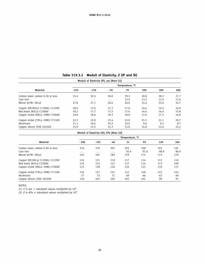
ASME B31.5-2016
Table 519.3.2 Moduli of Elasticity, E (IP and SI)
Moduli of Elasticity (IP), psi [Note (1)]
Temperature, °F
Material −325 −150 −50 70 200 300 400
Carbon steel, carbon 0.30 or less 31.4 30.5 30.0 29.5 28.8 28.3 27.7Cast iron . . . . . . . . . 13.4 13.2 12.9 12.6Monel (67Ni–30Cu) 27.8 27.1 26.6 26.0 25.4 25.0 24.7
Copper (99.90Cu) C12000, C12200 18.0 17.6 17.3 17.0 16.6 16.3 16.0Red brass (85Cu) C23000 18.2 17.7 17.5 17.0 16.6 16.4 15.8Copper nickel (90Cu–10Ni) C70600 19.0 18.6 18.3 18.0 17.6 17.3 16.9
Copper nickel (70Cu–30Ni) C71500 22.3 22.8 22.4 22.0 21.5 21.1 20.7Aluminum 11.1 10.6 10.3 10.0 9.6 9.2 8.7Copper silicon (3Si) C65500 15.9 15.5 15.3 15.0 14.6 14.4 14.1
Moduli of Elasticity (SI), kPa [Note (2)]
Temperature, °C
Material −198 −101 −46 21 93 149 204
Carbon steel, carbon 0.30 or less 216 210 207 203 198 195 191Cast iron . . . . . . . . . 92.4 91.0 88.9 86.9Monel (67Ni–30Cu) 192 187 183 179 175 173 170
Copper (99.90Cu) C12000, C12200 124 121 119 117 114 112 110Red brass (85Cu) C23000 125 122 121 117 114 113 109Copper nickel (90Cu–10Ni) C70600 131 128 126 124 121 119 117
Copper nickel (70Cu–30Ni) C71500 154 157 155 152 148 145 143Aluminum 77 73 71 69 66 63 60Copper silicon (3Si) C65500 110 107 105 103 101 99 97
NOTES:(1) E in psi p tabulated values multiplied by 106.(2) E in kPa p tabulated values multiplied by 106.
40
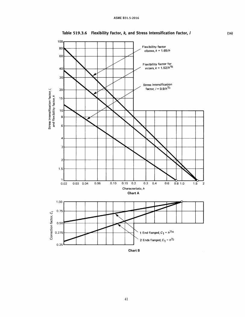
ASME B31.5-2016
Table 519.3.6 Flexibility Factor, k, and Stress Intensification Factor, i
41
(16)
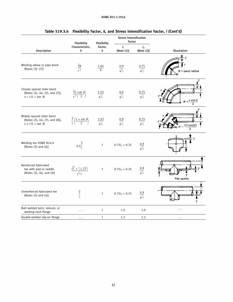
ASME B31.5-2016
Table 519.3.6 Flexibility Factor, k, and Stress Intensification Factor, i (Cont’d)
Stress IntensificationFactorFlexibility Flexibility
Characteristic, Factor, ii io
Description h k [Note (1)] [Note (2)] Illustration
Welding elbow or pipe bend 1.65h
0.9
h2⁄
3
0.75
h2⁄
3
TR
r 2[Notes (3)–(7)]
Closely spaced miter bend[Notes (3), (4), (5), and (7)], 1.52
h5⁄
6
0.9
h2⁄
3
0.75
h2⁄
3
Ts
r 2 �cot �
2 �s < r(1 + tan �)
Widely spaced miter bend[Notes (3), (4), (7), and (8)], 1.52
h5⁄
6
0.9
h2⁄
3
0.75
h2⁄
3
Tr �1 + cot �
2 �s ≥ r(1 + tan �)
Welding tee ASME B16.91 0.75io + 0.25 0.9
h2⁄
3
4.4Tr[Notes (3) and (4)]
Reinforced fabricatedtee with pad or saddle 1 0.75io + 0.25 0.9
h2⁄
3
(T + 1⁄ 2 T )5⁄
2
t3⁄2 r[Notes (3), (4), and (9)]
Unreinforced fabricated tee1 0.75io + 0.25 0.9
h2⁄
3
Tr[Notes (3) and (4)]
Butt welded joint, reducer, or . . .. . . 1 1.0 1.0
welding neck flange
Double-welded slip-on flange . . . 1 1.2 1.2 . . .
42
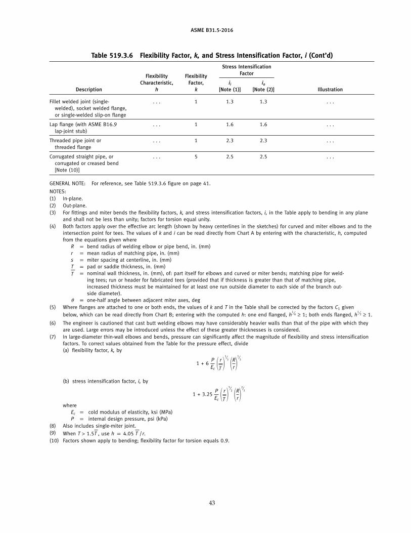
ASME B31.5-2016
Table 519.3.6 Flexibility Factor, k, and Stress Intensification Factor, i (Cont’d)
Stress IntensificationFactorFlexibility Flexibility
Characteristic, Factor, ii io
Description h k [Note (1)] [Note (2)] Illustration
Fillet welded joint (single- . . . 1 1.3 1.3 . . .welded), socket welded flange,or single-welded slip-on flange
Lap flange (with ASME B16.9 . . . 1 1.6 1.6 . . .lap-joint stub)
Threaded pipe joint or . . . 1 2.3 2.3 . . .threaded flange
Corrugated straight pipe, or . . . 5 2.5 2.5 . . .corrugated or creased bend[Note (10)]
GENERAL NOTE: For reference, see Table 519.3.6 figure on page 41.
NOTES:(1) In-plane.(2) Out-plane.(3) For fittings and miter bends the flexibility factors, k, and stress intensification factors, i, in the Table apply to bending in any plane
and shall not be less than unity; factors for torsion equal unity.(4) Both factors apply over the effective arc length (shown by heavy centerlines in the sketches) for curved and miter elbows and to the
intersection point for tees. The values of k and i can be read directly from Chart A by entering with the characteristic, h, computedfrom the equations given where
R p bend radius of welding elbow or pipe bend, in. (mm)r p mean radius of matching pipe, in. (mm)s p miter spacing at centerline, in. (mm)T p pad or saddle thickness, in. (mm)
p nominal wall thickness, in. (mm), of: part itself for elbows and curved or miter bends; matching pipe for weld-Ting tees; run or header for fabricated tees (provided that if thickness is greater than that of matching pipe,increased thickness must be maintained for at least one run outside diameter to each side of the branch out-side diameter).
� p one-half angle between adjacent miter axes, deg(5) Where flanges are attached to one or both ends, the values of k and T in the Table shall be corrected by the factors C1 given
below, which can be read directly from Chart B; entering with the computed h: one end flanged, h1⁄6 ≥ 1; both ends flanged, h
1⁄2 ≥ 1.
(6) The engineer is cautioned that cast butt welding elbows may have considerably heavier walls than that of the pipe with which theyare used. Large errors may be introduced unless the effect of these greater thicknesses is considered.
(7) In large-diameter thin-wall elbows and bends, pressure can significantly affect the magnitude of flexibility and stress intensificationfactors. To correct values obtained from the Table for the pressure effect, divide(a) flexibility factor, k, by
1 + 6PEc
� r
T �1⁄
3 �Rr�1⁄
3
(b) stress intensification factor, i, by
1 + 3.25PEc
� r
T �5⁄
2 �Rr�2⁄
3
whereEc p cold modulus of elasticity, ksi (MPa)P p internal design pressure, psi (kPa)
(8) Also includes single-miter joint.(9) When T > 1.5T , use h p 4.05 T /r.(10) Factors shown apply to bending; flexibility factor for torsion equals 0.9.
43
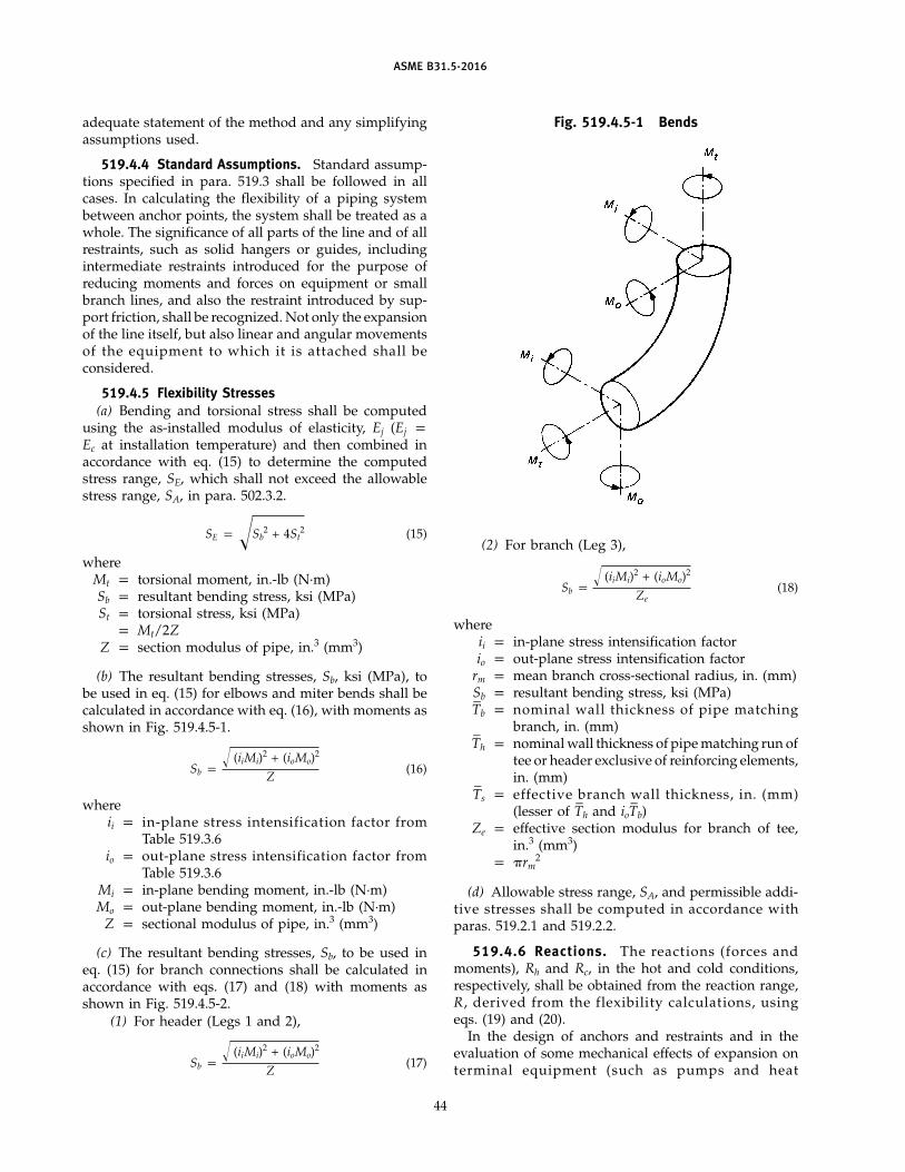
ASME B31.5-2016
adequate statement of the method and any simplifyingassumptions used.
519.4.4 Standard Assumptions. Standard assump-tions specified in para. 519.3 shall be followed in allcases. In calculating the flexibility of a piping systembetween anchor points, the system shall be treated as awhole. The significance of all parts of the line and of allrestraints, such as solid hangers or guides, includingintermediate restraints introduced for the purpose ofreducing moments and forces on equipment or smallbranch lines, and also the restraint introduced by sup-port friction, shall be recognized. Not only the expansionof the line itself, but also linear and angular movementsof the equipment to which it is attached shall beconsidered.
519.4.5 Flexibility Stresses(a) Bending and torsional stress shall be computed
using the as-installed modulus of elasticity, Ej (Ej pEc at installation temperature) and then combined inaccordance with eq. (15) to determine the computedstress range, SE, which shall not exceed the allowablestress range, SA, in para. 502.3.2.
SE p �Sb2 + 4St
2 (15)
whereMt p torsional moment, in.-lb (N·m)Sb p resultant bending stress, ksi (MPa)St p torsional stress, ksi (MPa)
p Mt/2ZZ p section modulus of pipe, in.3 (mm3)
(b) The resultant bending stresses, Sb, ksi (MPa), tobe used in eq. (15) for elbows and miter bends shall becalculated in accordance with eq. (16), with moments asshown in Fig. 519.4.5-1.
Sb p� (iiMi)2 + (ioMo)2
Z(16)
whereii p in-plane stress intensification factor from
Table 519.3.6io p out-plane stress intensification factor from
Table 519.3.6Mi p in-plane bending moment, in.-lb (N·m)Mo p out-plane bending moment, in.-lb (N·m)
Z p sectional modulus of pipe, in.3 (mm3)
(c) The resultant bending stresses, Sb, to be used ineq. (15) for branch connections shall be calculated inaccordance with eqs. (17) and (18) with moments asshown in Fig. 519.4.5-2.
(1) For header (Legs 1 and 2),
Sb p� (iiMi)2 + (ioMo)2
Z(17)
44
Fig. 519.4.5-1 Bends
(2) For branch (Leg 3),
Sb p� (iiMi)2 + (ioMo)2
Ze(18)
whereii p in-plane stress intensification factorio p out-plane stress intensification factor
rm p mean branch cross-sectional radius, in. (mm)Sb p resultant bending stress, ksi (MPa)T–
b p nominal wall thickness of pipe matchingbranch, in. (mm)
T–
h p nominal wall thickness of pipe matching run oftee or header exclusive of reinforcing elements,in. (mm)
T–
s p effective branch wall thickness, in. (mm)(lesser of T
–h and ioT
–b)
Ze p effective section modulus for branch of tee,in.3 (mm3)
p �rm2
(d) Allowable stress range, SA, and permissible addi-tive stresses shall be computed in accordance withparas. 519.2.1 and 519.2.2.
519.4.6 Reactions. The reactions (forces andmoments), Rh and Rc, in the hot and cold conditions,respectively, shall be obtained from the reaction range,R, derived from the flexibility calculations, usingeqs. (19) and (20).
In the design of anchors and restraints and in theevaluation of some mechanical effects of expansion onterminal equipment (such as pumps and heat
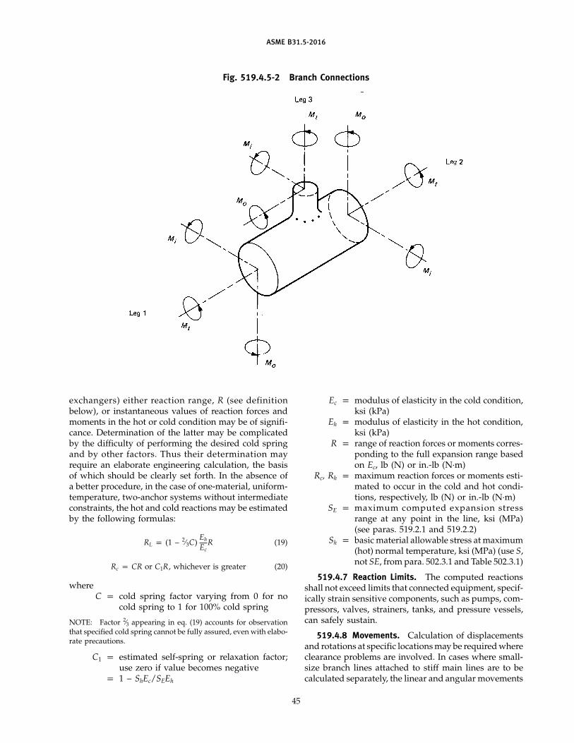
ASME B31.5-2016
Fig. 519.4.5-2 Branch Connections
exchangers) either reaction range, R (see definitionbelow), or instantaneous values of reaction forces andmoments in the hot or cold condition may be of signifi-cance. Determination of the latter may be complicatedby the difficulty of performing the desired cold springand by other factors. Thus their determination mayrequire an elaborate engineering calculation, the basisof which should be clearly set forth. In the absence ofa better procedure, in the case of one-material, uniform-temperature, two-anchor systems without intermediateconstraints, the hot and cold reactions may be estimatedby the following formulas:
RL p (1 − 2⁄3C)Eh
EcR (19)
Rc p CR or C1R, whichever is greater (20)
whereC p cold spring factor varying from 0 for no
cold spring to 1 for 100% cold spring
NOTE: Factor 2⁄3 appearing in eq. (19) accounts for observationthat specified cold spring cannot be fully assured, even with elabo-rate precautions.
C1 p estimated self-spring or relaxation factor;use zero if value becomes negative
p 1 − ShEc/SEEh
45
Ec p modulus of elasticity in the cold condition,ksi (kPa)
Eh p modulus of elasticity in the hot condition,ksi (kPa)
R p range of reaction forces or moments corres-ponding to the full expansion range basedon Ec, lb (N) or in.-lb (N·m)
Rc, Rh p maximum reaction forces or moments esti-mated to occur in the cold and hot condi-tions, respectively, lb (N) or in.-lb (N·m)
SE p maximum computed expansion stressrange at any point in the line, ksi (MPa)(see paras. 519.2.1 and 519.2.2)
Sh p basic material allowable stress at maximum(hot) normal temperature, ksi (MPa) (use S,not SE, from para. 502.3.1 and Table 502.3.1)
519.4.7 Reaction Limits. The computed reactionsshall not exceed limits that connected equipment, specif-ically strain sensitive components, such as pumps, com-pressors, valves, strainers, tanks, and pressure vessels,can safely sustain.
519.4.8 Movements. Calculation of displacementsand rotations at specific locations may be required whereclearance problems are involved. In cases where small-size branch lines attached to stiff main lines are to becalculated separately, the linear and angular movements
ASME B31.5-2016
of the junction point must be calculated or estimatedfor proper analysis of the branch.
520 DESIGN OF PIPE SUPPORTING ELEMENTS
520.1 General
Loads on equipment supporting, bracing, guiding, oranchoring piping include, in addition to weight effects,loads due to service pressure and temperatures, vibra-tion, wind, earthquake, shock, erection contingencies(including testing), thermal expansion and contraction,and differential settlement of foundations, all as definedin section 501. The design of all elements supportingor restraining pipe shall have regard to the degree ofprobability of concurrence of loads and whether theyare sustained or tend to relax themselves as defined inpara. 519.2.1.
520.1.1 Objectives. Supporting elements shall bedesigned to prevent the loadings and deflections due tothe influences delineated in para. 520.1 from causingone of the following:
(a) piping stresses in excess of those permitted in thisSection of the Code
(b) leakage at joints(c) detrimental distortion of connected equipment
(such as pumps, turbines, valves, etc.) resulting fromexcessive forces and moments
(d) excessive stresses in the pipe supporting (orrestraining) elements themselves
(e) resonance with imposed vibrations(f) excessive interference with the thermal expansion
and contraction of a piping system that is otherwiseadequately flexible
(g) unintentional disengagement of the piping fromits supports
(h) excessive piping sag in systems requiring drain-age slope
520.1.2 Allowable Stresses in Piping. The design ofpiping-support elements shall be such that the sustainedpiping stresses shall not exceed the allowable value asdefined in paras. 502.3.2(d) and 523.2.2(f)(4).
520.1.3 Allowable Stresses in Piping Support andRestraint Components
(a) The allowable stress for the base material of allparts of supporting and restraint assemblies shall notexceed the appropriate S value taken from para. 502.3.1and Table 502.3.1 including Notes except as permittedin 520.1.3(b). It is not necessary to include joint factors.The allowable stress shall be reduced 25% for threadedmembers and for welds in support assemblies or forattachments to piping. For threaded members stressesshall be based on the root area of the threads.
(b) An increase in allowable stress of 20% shall beallowed for short-time overloading conditions.
46
(c) For requirements pertaining to springs, seepara. 521.3.2.
(d) For requirements pertaining to anchors andguides, see paras. 521.1.3 and 521.1.4.
(e) The principles in para. 502.3.1(d) are not applicableto design of springs.
(f) Pipe support and hanger components conformingto the requirements of para. 502.3.1 may have an increasein their working stress to 80% of minimum yield strengthat room temperature for the period of hydrostatic test-ing. This applies only to supports that have been engi-neered by the designer and not to standard catalog itemsunless they have been carefully analyzed by thedesigner.
520.1.4 Materials — Steel. All equipment for per-manent supports and restraints shall be fabricated fromdurable materials suitable for the service conditions.Unless otherwise permitted in para. 520.1.5, steel shallbe used for pipe supporting elements. All materials shallbe capable of meeting the respective standard specifica-tions given in Table 523.1 with regard to the tests andphysical properties.
Parts of supporting elements that are subjected princi-pally to bending or tension loads and that are subjectedto working temperatures for which carbon steel is notrecommended shall be made of suitable alloy steel, orshall be protected so that the temperature of the support-ing members will be maintained within their tempera-ture limits.
520.1.5 Materials Other Than Those inPara. 520.1.4. Cast iron may be used for roller bases,rollers, anchor bases, brackets, and parts of pipe support-ing elements upon which the loading will be mainlythat of compression. Malleable or nodular iron castingsmay be used for pipe clamps, beam clamps, hangerflanges, clips, bases, swivel rings, and parts of pipe sup-porting elements. Treated wood may be used for pipesupporting elements that are primarily in compressionwhen the metal temperatures are at or below ambienttemperature.
Materials other than those listed in Table 523.1 maybe employed to take advantage of their superior proper-ties, in specialty items such as constant support hangers.In such cases, allowable stresses shall be determined inaccordance with the principles given in para. 502.3.1.
520.1.6 Protective Coatings(a) Under conditions causing mild corrosion, such as
atmospheric rusting, which are not of an intensity towarrant the use of corrosion resistant materials, a dura-ble protective coating, such as hot-dipped galvanizing,weather resistant paint, or other suitable protection,should be applied to all parts after fabrication or afterinstallation.
ASME B31.5-2016
(b) Under any conditions, exposed screw threads onparts of the equipment where corrosion resistant materi-als are not used shall be greased immediately after fabri-cation. Paints, slushes, or other suitable protectivecoatings may be used instead of grease.
520.1.7 Threaded Components. Threads shall be inaccordance with ASME B1.1, except that other threadforms may be used to facilitate adjustment under heavyloads. All threaded adjustments shall be provided withlock nuts or be locked by other positive means. Turn-buckles and adjusting nuts shall have the full length ofthread in service. Means shall be provided for determin-ing that full length of thread is in service.
521 DESIGN LOADS FOR PIPE SUPPORTINGELEMENTS
521.1 General
521.1.1 Forces and moments at pipe supportingelements caused by thermal expansion or contractionshall be determined as necessary.
521.1.2 Weight calculations for gas, vapor, orsafety valve discharge piping should not include theweight of liquid if the possibility of these lines containingliquid is remote and provided the lines are not subjectedto hydrostatic tests.
521.1.3 Restraints, such as anchors and guides,shall be provided where necessary to control movementor to direct expansion and/or other effects into thoseportions of the system that are adequate to absorb themfor the purpose of protecting terminal equipment and/or other (weaker) portions of the system. The effect offriction in other supports of the system shall be consid-ered in the design of such anchors and guides.
521.1.4 Anchors or guides for expansion joints ofthe corrugated or slip-type (or variants of these types)shall be designed to resist end forces from fluid pressureand frictional or other applicable resistance to jointmovement, in addition to other loadings.
521.2 Resilient Variable-Support and Constant-Support Types
Reactions or load calculations for resilient or constanteffort type supports, such as springs or weight loadedsupports and braces, shall be based on the maximumworking conditions of the piping. However, the supportshall be capable of carrying the total load under testconditions, unless additional support is provided forthe test period. The amount of variation that can betolerated shall be determined by incorporating thechange in supporting effect in the flexibility analysis orshall be based on such considerations as bending effect,control of piping elevation, allowable terminalreactions, etc.
47
521.3 Design Details
521.3.1 General(a) Hanger Rods. Safe axial loads for threaded hanger
rods shall be based on the root area of the threads andsubject to 25% reduction in allowable stress as in para.520.1.3(a). Pipe, straps, or bars of strength and effectarea equal to the equivalent hanger rod may be usedinstead of hanger rods. See Table 521.3.1.
(b) Chains. Chain may be used for pipe hangers andshall be designed in accordance with (a).
(c) Sliding Supports. Sliding supports (or shoes) andbrackets shall be designed to resist the forces due tofriction in addition to the loads imposed by bearing.The dimensions of the support shall provide for theexpected movement of the supported piping.
(d) At point of support subject to horizontal move-ment, the movement shall be provided for by the swingof long hanger rods or chains or by the use of trolleys,rollers, sliding, or swinging supports.
(e) Covering on insulated piping shall be protectedfrom damage at all hanger locations. Saddles, bases, orsuitable shields properly constructed and secured to thecovered pipe shall be used at points of roller, base, andtrapeze support.
(f) Lugs, plates, angle clips, etc., used as part of anassembly for the support or guiding of pipe may bewelded directly to the pipe provided the material is ofgood weldable quality and the design is adequate forthe load. Preheating, welding, and postheating shall bein accordance with the rules of Chapter V.
(g) See MSS SP-58 for typical design details.
521.3.2 Spring Supports. Spring type supportsshall be provided with means to prevent misalignment,buckling, or eccentric loading of the spring, and to pre-vent unintentional disengagement of the load. Materialsshall be in accordance with the provisions of paras.520.1.4 and 520.1.5. Constant support spring hangersshall be designed to provide a substantially uniformsupporting force throughout the range of travel. Allspring elements shall be provided with means of adjust-ment for the pipe position in the operating and nonop-erating condition. Means shall be provided to preventoverstressing the spring due to excessive deflections. Itis desirable that all spring hangers be provided withposition indicators.
521.3.3 Counterweights. Counterweights whenused instead of spring hangers shall be provided withstops to prevent overtravel. Weights shall be positivelysecured. Chains, cables, hanger and rocker arm details,or other devices used to attach the counterweight loadto the piping, shall be subject to requirements ofpara. 521.3.1.
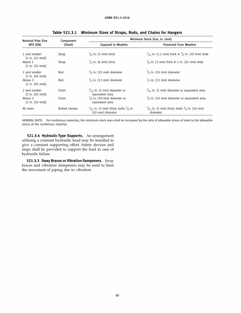
ASME B31.5-2016
Table 521.3.1 Minimum Sizes of Straps, Rods, and Chains for Hangers
Minimum Stock Size, in. (mm)Nominal Pipe Size ComponentNPS (DN) (Steel) Exposed to Weather Protected From Weather
1 and smaller Strap 1⁄8 in. (3 mm) thick 1⁄16 in. (1.5 mm) thick � 3⁄4 in. (19 mm) wide[1 in. (25 mm)]
Above 1 Strap 1⁄4 in. (6 mm) thick 1⁄8 in. (3 mm) thick � 1 in. (25 mm) wide[1 in. (25 mm)]
2 and smaller Rod 3⁄8 in. (10 mm) diameter 3⁄8 in. (10 mm) diameter[2 in. (50 mm)]
Above 2 Rod 1⁄2 in. (13 mm) diameter 1⁄2 in. (13 mm) diameter[2 in. (50 mm)]
2 and smaller Chain 3⁄16 in. (5 mm) diameter or 3⁄16 in. (5 mm) diameter or equivalent area[2 in. (50 mm)] equivalent area
Above 2 Chain 3⁄8 in. (10 mm) diameter or 3⁄8 in. (10 mm) diameter or equivalent area[2 in. (50 mm)] equivalent area
All sizes Bolted clamps 3⁄16 in. (5 mm) thick; bolts 3⁄8 in. 3⁄16 in. (5 mm) thick; bolts 3⁄8 in. (10 mm)(10 mm) diameter diameter
GENERAL NOTE: For nonferrous materials, the minimum stock area shall be increased by the ratio of allowable stress of steel to the allowablestress of the nonferrous material.
521.3.4 Hydraulic-Type Supports. An arrangementutilizing a constant hydraulic head may be installed togive a constant supporting effort. Safety devices andstops shall be provided to support the load in case ofhydraulic failure.
521.3.5 Sway Braces or Vibration Dampeners. Swaybraces and vibration dampeners may be used to limitthe movement of piping due to vibration.
48
ASME B31.5-2016
Chapter IIIMaterials
523 MATERIALS — GENERAL REQUIREMENTS523.1 Materials and Specifications
The materials used shall conform to the specificationslisted in Table 523.1 or shall meet the requirements ofthis Code for materials not so established.
523.1.1 Listed Materials(a) Any material used in pressure containing piping
components shall conform to a listed specification exceptas provided in para. 523.1.2.
(b) Materials manufactured to specification editionsother than those listed in Nonmandatory Appendix Ameet the requirements of this Code, provided
(1) the material meets the listed edition’s require-ments for chemical composition and heat treatmentcondition
(2) the material grain size requirements are thesame as the listed edition
(3) the material toughness requirements are thesame as the listed edition
(4) the material tensile and yield strength require-ments are the same as the listed edition
(5) the material has been tested and examined inaccordance with the requirements of the listed edition
523.1.2 Unlisted Materials. Unlisted materials maybe used provided they conform to a published specifica-tion covering chemistry, physical, and mechanical prop-erties, method and process of manufacture, heattreatment, and quality control and otherwise meet therequirements of this Code. Allowable stresses shall bedetermined in accordance with the applicable allowablestress basis of this Code or a more conservative basis.
523.1.3 Unknown Materials. Materials of unknownspecification shall not be used for pressure-containingpiping components.
523.1.4 Reclaimed Materials. Reclaimed pipe andother piping components may be used, provided theyare properly identified as conforming to a listed or pub-lished specification (para. 523.1.1 or 523.1.2) and other-wise meet the requirements of this Code. Sufficientcleaning and inspection shall be made to determine min-imum wall thickness and freedom from imperfectionsthat would be unacceptable in the intended service.
523.2 Limitations on Materials523.2.1 General. The materials listed in
Table 502.3.1 shall not be used at design metal tempera-tures above those for which stress values are given inthe Table. The materials shall not be used below the
49
minimum temperature listed unless they meet therequirements of para. 523.2.2.
523.2.2 Impact Tests. Materials subject to designmetal temperatures below the minimum temperaturelisted in Table 502.3.1 and in (f)(5), except for thoseexempted in (f)(4) and (f)(5), shall be impact tested asrequired by UG-84 of Section VIII, Division 1, of theASME BPV Code. The following requirements shall alsobe met:
(a) A welded test section shall be prepared foreach P-Number and Group Number as defined byASME Section IX and in accordance with UG-84(e).
(b) If the material to be used is not certified, test sec-tions shall be prepared from each piece of pipe, plate,or tubing used.
(c) One set of impact-test specimens shall be takenacross the weld (the metal tested is the weld metal) withthe notch in the weld, and one set shall be taken similarlywith the notch at the fusion line (the metal tested is thebase metal).
(d) Impact test specimens shall be cooled to a temper-ature not higher than the lowest temperature to whichthe pipe, plate, or tubing may be subjected in itsoperating cycle.
(e) One set of impact-test specimens with the notchin the weld metal and one set with the notch in theheat-affected zone shall be made for each range of pipethicknesses as required by ASME Section IX.
(f) The following materials are exempted from therequirements for impact testing:
(1) Impact tests are not required for aluminum:Types 304 or CF8, 304L or CF3, 316 or CF8M, and 321austenitic stainless steel; copper; red brass; copper–nickel alloys; and nickel–copper alloys.
(2) Impact tests are not required for bolting mate-rial conforming with A193, Grade B7, for use at tempera-tures not lower than −55°F (−48°C).
(3) Impact tests are not required for bolting materi-als conforming with A320, Grades L7, L10, and L43, attemperatures above −150°F (−101°C) or above −225°F(−143°C) for A320, Grade L9.
(4) Impact tests are not required for ferrous materi-als used in fabricating a piping system for metal temper-atures colder than −20°F (−29°C) down to −150°F(−101°C), provided the maximum circumferential orlongitudinal tensile stress resulting from coincidentpressure, thermal contraction, or bending betweensupports does not exceed 35% of the allowable stress
(16)
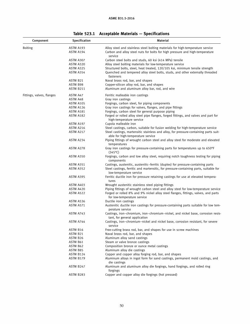
ASME B31.5-2016
Table 523.1 Acceptable Materials — Specifications
Component Specification Material
Bolting ASTM A193 Alloy steel and stainless steel bolting materials for high-temperature serviceASTM A194 Carbon and alloy steel nuts for bolts for high pressure and high-temperature
serviceASTM A307 Carbon steel bolts and studs, 60 ksi (414 MPa) tensileASTM A320 Alloy steel bolting materials for low-temperature serviceASTM A325 Structured bolts, steel, heat treated, 120/105 ksi, minimum tensile strengthASTM A354 Quenched and tempered alloy steel bolts, studs, and other externally threaded
fastenersASTM B21 Naval brass rod, bar, and shapesASTM B98 Copper-silicon alloy rod, bar, and shapesASTM B211 Aluminum and aluminum alloy bar, rod, and wire
Fittings, valves, flanges ASTM A47 Ferritic malleable iron castingsASTM A48 Gray iron castingsASTM A105 Forgings, carbon steel, for piping componentsASTM A126 Gray iron castings for valves, flanges, and pipe fittingsASTM A181 Forgings, carbon steel for general purpose pipingASTM A182 Forged or rolled alloy steel pipe flanges, forged fittings, and valves and part for
high-temperature serviceASTM A197 Cupola malleable ironASTM A216 Steel castings, carbon, suitable for fusion welding for high-temperature serviceASTM A217 Steel castings, martensitic stainless and alloy, for pressure-containing parts suit-
able for high-temperature serviceASTM A234 Piping fittings of wrought carbon steel and alloy steel for moderate and elevated
temperaturesASTM A278 Gray iron castings for pressure-containing parts for temperatures up to 650°F
(345°C)ASTM A350 Forgings, carbon and low alloy steel, requiring notch toughness testing for piping
componentsASTM A351 Castings, austenitic, austenitic–ferritic (duplex) for pressure-containing partsASTM A352 Steel castings, ferritic and martensitic, for pressure-containing parts, suitable for
low-temperature serviceASTM A395 Ferritic ductile iron for pressure retaining castings for use at elevated tempera-
turesASTM A403 Wrought austenitic stainless steel piping fittingsASTM A420 Piping fittings of wrought carbon steel and alloy steel for low-temperature serviceASTM A522 Forged or rolled 8% and 9% nickel alloy steel flanges, fittings, valves, and parts
for low-temperature serviceASTM A536 Ductile iron castingsASTM A571 Austenitic ductile iron castings for pressure-containing parts suitable for low tem-
perature serviceASTM A743 Castings, iron–chromium, iron–chromium–nickel, and nickel base, corrosion resis-
tant, for general applicationASTM A744 Castings, iron–chromium–nickel and nickel base, corrosion resistant, for severe
serviceASTM B16 Free-cutting brass rod, bar, and shapes for use in screw machinesASTM B21 Naval brass rod, bar, and shapesASTM B26 Aluminum alloy sand castingsASTM B61 Steam or valve bronze castingsASTM B62 Composition bronze or ounce metal castingsASTM B85 Aluminum alloy die castingsASTM B124 Copper and copper alloy forging rod, bar, and shapesASTM B179 Aluminum alloys in ingot form for sand castings, permanent mold castings, and
die castingsASTM B247 Aluminum and aluminum alloy die forgings, hand forgings, and rolled ring
forgingsASTM B283 Copper and copper alloy die forgings (hot pressed)
50
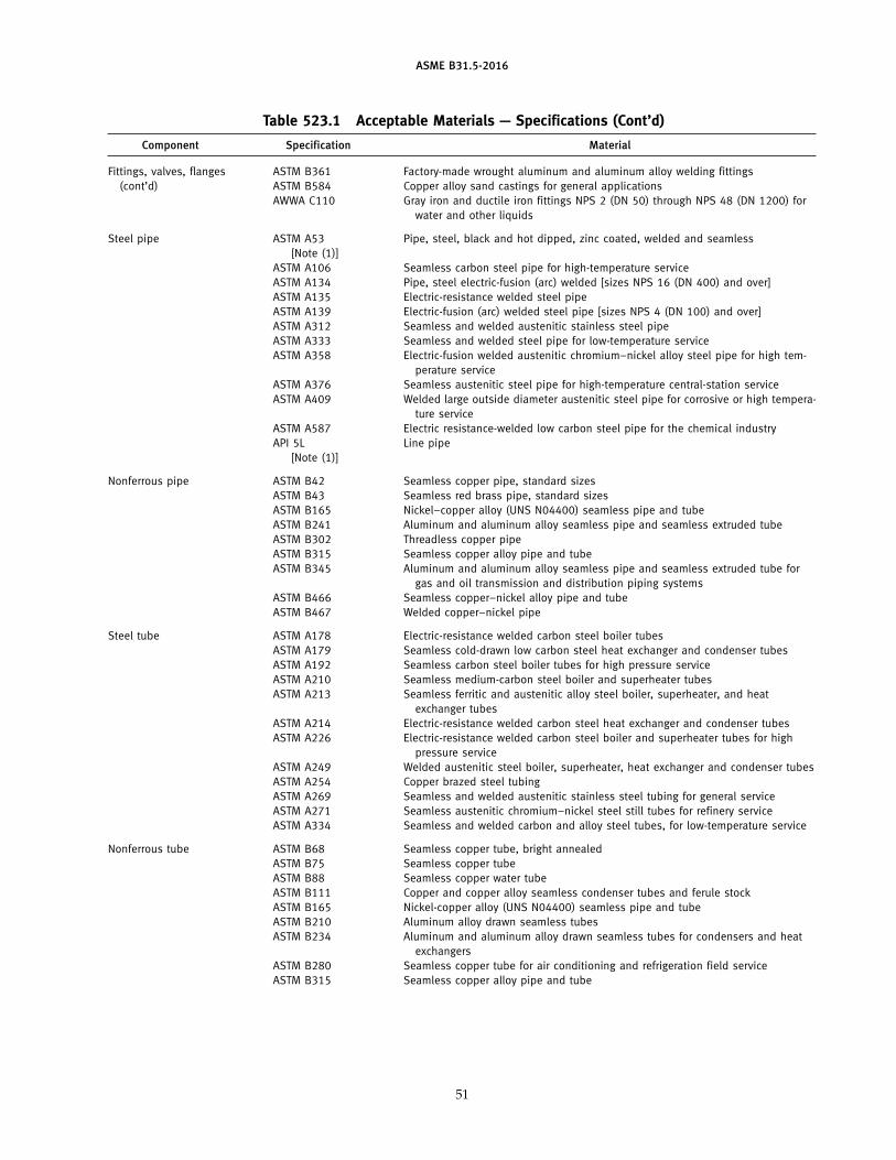
ASME B31.5-2016
Table 523.1 Acceptable Materials — Specifications (Cont’d)
Component Specification Material
Fittings, valves, flanges ASTM B361 Factory-made wrought aluminum and aluminum alloy welding fittings(cont’d) ASTM B584 Copper alloy sand castings for general applications
AWWA C110 Gray iron and ductile iron fittings NPS 2 (DN 50) through NPS 48 (DN 1200) forwater and other liquids
Steel pipe ASTM A53 Pipe, steel, black and hot dipped, zinc coated, welded and seamless[Note (1)]
ASTM A106 Seamless carbon steel pipe for high-temperature serviceASTM A134 Pipe, steel electric-fusion (arc) welded [sizes NPS 16 (DN 400) and over]ASTM A135 Electric-resistance welded steel pipeASTM A139 Electric-fusion (arc) welded steel pipe [sizes NPS 4 (DN 100) and over]ASTM A312 Seamless and welded austenitic stainless steel pipeASTM A333 Seamless and welded steel pipe for low-temperature serviceASTM A358 Electric-fusion welded austenitic chromium–nickel alloy steel pipe for high tem-
perature serviceASTM A376 Seamless austenitic steel pipe for high-temperature central-station serviceASTM A409 Welded large outside diameter austenitic steel pipe for corrosive or high tempera-
ture serviceASTM A587 Electric resistance-welded low carbon steel pipe for the chemical industryAPI 5L Line pipe
[Note (1)]
Nonferrous pipe ASTM B42 Seamless copper pipe, standard sizesASTM B43 Seamless red brass pipe, standard sizesASTM B165 Nickel–copper alloy (UNS N04400) seamless pipe and tubeASTM B241 Aluminum and aluminum alloy seamless pipe and seamless extruded tubeASTM B302 Threadless copper pipeASTM B315 Seamless copper alloy pipe and tubeASTM B345 Aluminum and aluminum alloy seamless pipe and seamless extruded tube for
gas and oil transmission and distribution piping systemsASTM B466 Seamless copper–nickel alloy pipe and tubeASTM B467 Welded copper–nickel pipe
Steel tube ASTM A178 Electric-resistance welded carbon steel boiler tubesASTM A179 Seamless cold-drawn low carbon steel heat exchanger and condenser tubesASTM A192 Seamless carbon steel boiler tubes for high pressure serviceASTM A210 Seamless medium-carbon steel boiler and superheater tubesASTM A213 Seamless ferritic and austenitic alloy steel boiler, superheater, and heat
exchanger tubesASTM A214 Electric-resistance welded carbon steel heat exchanger and condenser tubesASTM A226 Electric-resistance welded carbon steel boiler and superheater tubes for high
pressure serviceASTM A249 Welded austenitic steel boiler, superheater, heat exchanger and condenser tubesASTM A254 Copper brazed steel tubingASTM A269 Seamless and welded austenitic stainless steel tubing for general serviceASTM A271 Seamless austenitic chromium–nickel steel still tubes for refinery serviceASTM A334 Seamless and welded carbon and alloy steel tubes, for low-temperature service
Nonferrous tube ASTM B68 Seamless copper tube, bright annealedASTM B75 Seamless copper tubeASTM B88 Seamless copper water tubeASTM B111 Copper and copper alloy seamless condenser tubes and ferule stockASTM B165 Nickel-copper alloy (UNS N04400) seamless pipe and tubeASTM B210 Aluminum alloy drawn seamless tubesASTM B234 Aluminum and aluminum alloy drawn seamless tubes for condensers and heat
exchangersASTM B280 Seamless copper tube for air conditioning and refrigeration field serviceASTM B315 Seamless copper alloy pipe and tube
51
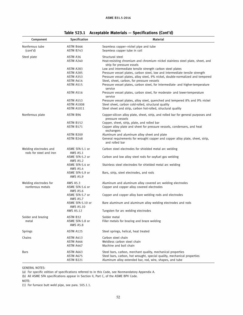
ASME B31.5-2016
Table 523.1 Acceptable Materials — Specifications (Cont’d)
Component Specification Material
Nonferrous tube ASTM B466 Seamless copper–nickel pipe and tube(cont’d) ASTM B743 Seamless copper tube in coil
Steel plate ASTM A36 Structural steelASTM A240 Heat-resisting chromium and chromium–nickel stainless steel plate, sheet, and
strip for pressure esselsASTM A283 Low and intermediate tensile strength carbon steel platesASTM A285 Pressure vessel plates, carbon steel, low and intermediate tensile strengthASTM A353 Pressure vessel plates, alloy steel, 9% nickel, double-normalized and temperedASTM A414 Steel, sheet, carbon, for pressure vesselsASTM A515 Pressure vessel plates, carbon steel, for intermediate- and higher-temperature
serviceASTM A516 Pressure vessel plates, carbon steel, for moderate- and lower-temperature
serviceASTM A553 Pressure vessel plates, alloy steel, quenched and tempered 8% and 9% nickelASTM A1008 Steel sheet, carbon cold-rolled, structural qualityASTM A1011 Steel sheet and strip, carbon hot-rolled, structural quality
Nonferrous plate ASTM B96 Copper-silicon alloy plate, sheet, strip, and rolled bar for general purposes andpressure vessels
ASTM B152 Copper, sheet, strip, plate, and rolled barASTM B171 Copper alloy plate and sheet for pressure vessels, condensers, and heat
exchangersASTM B209 Aluminum and aluminum alloy sheet and plateASTM B248 General requirements for wrought copper and copper alloy plate, sheet, strip,
and rolled bar
Welding electrodes and ASME SFA-5.1 or Carbon steel electrodes for shielded metal arc weldingrods for steel and iron AWS A5.1
ASME SFA-5.2 or Carbon and low alloy steel rods for oxyfuel gas weldingAWS A5.2
ASME SFA-5.4 or Stainless steel electrodes for shielded metal arc weldingAWS A5.4
ASME SFA-5.9 or Bars, strip, steel electrodes, and rodsAWS A5.9
Welding electrodes for AWS A5.3 Aluminum and aluminum alloy covered arc welding electrodesnonferrous metals ASME SFA-5.6 or Copper and copper alloy covered electrodes
AWS A5.6ASME SFA-5.7 or Copper and copper alloy bare welding rods and electrodes
AWS A5.7ASME SFA-5.10 or Bare aluminum and aluminum alloy welding electrodes and rods
AWS A5.10AWS A5.12 Tungsten for arc welding electrodes
Solder and brazing ASTM B32 Solder metalmetal ASME SFA-5.8 or Filler metals for brazing and braze welding
AWS A5.8
Springs ASTM A125 Steel springs, helical, heat treated
Chains ASTM A413 Carbon steel chainASTM A466 Weldless carbon steel chainASTM A467 Machine and boil chain
Bars ASTM A663 Steel bars, carbon, merchant quality, mechanical propertiesASTM A675 Steel bars, carbon, hot wrought, special quality, mechanical propertiesASTM B221 Aluminum alloy extended bar, rod, wire, shapes, and tube
GENERAL NOTES:(a) For specific edition of specifications referred to in this Code, see Nonmandatory Appendix A.(b) All ASME SFA specifications appear in Section II, Part C, of the ASME BPV Code.
NOTE:(1) For furnace butt weld pipe, see para. 505.1.1.
52
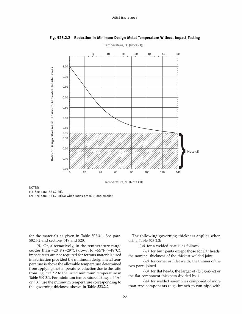
ASME B31.5-2016
Fig. 523.2.2 Reduction in Minimum Design Metal Temperature Without Impact Testing
Temperature, °C [Note (1)]
0 10 20 30 40 50 60
Temperature, °F [Note (1)]
0 20 40 60 80 100 120 140
Rat
io o
f D
esig
n S
tres
ses
in T
ensi
on
to
Allo
wab
le T
ensi
le S
tres
s 1.00
0.90
0.80
0.70
0.60
0.50
0.40
0.35
0.30
0.20
0.10
0.00
Note (2)
NOTES:(1) See para. 523.2.2(f).(2) See para. 523.2.2(f)(4) when ratios are 0.35 and smaller.
for the materials as given in Table 502.3.1. See para.502.3.2 and sections 519 and 520.
(5) Or, alternatively, in the temperature rangecolder than −20°F (−29°C) down to −55°F (−48°C),impact tests are not required for ferrous materials usedin fabrication provided the minimum design metal tem-perature is above the allowable temperature determinedfrom applying the temperature reduction due to the ratiofrom Fig. 523.2.2 to the listed minimum temperature inTable 502.3.1. For minimum temperature listings of “A”or “B,” use the minimum temperature corresponding tothe governing thickness shown in Table 523.2.2.
53
The following governing thickness applies whenusing Table 523.2.2:
(-a) for a welded part is as follows:(-1) for butt joints except those for flat heads,
the nominal thickness of the thickest welded joint(-2) for corner or fillet welds, the thinner of the
two parts joined(-3) for flat heads, the larger of (f)(5)(-a)(-2) or
the flat component thickness divided by 4(-4) for welded assemblies composed of more
than two components (e.g., branch-to-run pipe with
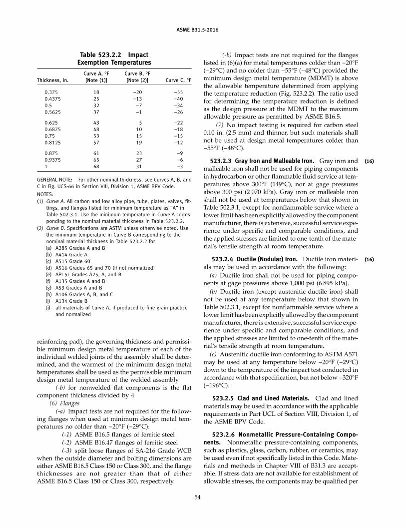
ASME B31.5-2016
Table 523.2.2 ImpactExemption Temperatures
Curve A, °F Curve B, °FThickness, in. [Note (1)] [Note (2)] Curve C, °F
0.375 18 −20 −550.4375 25 −13 −400.5 32 −7 −340.5625 37 −1 −26
0.625 43 5 −220.6875 48 10 −180.75 53 15 −150.8125 57 19 −12
0.875 61 23 −90.9375 65 27 −61 68 31 −3
GENERAL NOTE: For other nominal thickness, see Curves A, B, andC in Fig. UCS-66 in Section VIII, Division 1, ASME BPV Code.
NOTES:(1) Curve A. All carbon and low alloy pipe, tube, plates, valves, fit-
tings, and flanges listed for minimum temperature as “A” inTable 502.3.1. Use the minimum temperature in Curve A corres-ponding to the nominal material thickness in Table 523.2.2.
(2) Curve B. Specifications are ASTM unless otherwise noted. Usethe minimum temperature in Curve B corresponding to thenominal material thickness in Table 523.2.2 for(a) A285 Grades A and B(b) A414 Grade A(c) A515 Grade 60(d) A516 Grades 65 and 70 (if not normalized)(e) API 5L Grades A25, A, and B(f) A135 Grades A and B(g) A53 Grades A and B(h) A106 Grades A, B, and C(i) A134 Grade B(j) all materials of Curve A, if produced to fine grain practice
and normalized
reinforcing pad), the governing thickness and permissi-ble minimum design metal temperature of each of theindividual welded joints of the assembly shall be deter-mined, and the warmest of the minimum design metaltemperatures shall be used as the permissible minimumdesign metal temperature of the welded assembly
(-b) for nonwelded flat components is the flatcomponent thickness divided by 4
(6) Flanges(-a) Impact tests are not required for the follow-
ing flanges when used at minimum design metal tem-peratures no colder than −20°F (−29°C):
(-1) ASME B16.5 flanges of ferritic steel(-2) ASME B16.47 flanges of ferritic steel(-3) split loose flanges of SA-216 Grade WCB
when the outside diameter and bolting dimensions areeither ASME B16.5 Class 150 or Class 300, and the flangethicknesses are not greater than that of eitherASME B16.5 Class 150 or Class 300, respectively
54
(-b) Impact tests are not required for the flangeslisted in (6)(a) for metal temperatures colder than −20°F(−29°C) and no colder than −55°F (−48°C) provided theminimum design metal temperature (MDMT) is abovethe allowable temperature determined from applyingthe temperature reduction (Fig. 523.2.2). The ratio usedfor determining the temperature reduction is definedas the design pressure at the MDMT to the maximumallowable pressure as permitted by ASME B16.5.
(7) No impact testing is required for carbon steel0.10 in. (2.5 mm) and thinner, but such materials shallnot be used at design metal temperatures colder than−55°F (−48°C).
523.2.3 Gray Iron and Malleable Iron. Gray iron andmalleable iron shall not be used for piping componentsin hydrocarbon or other flammable fluid service at tem-peratures above 300°F (149°C), nor at gage pressuresabove 300 psi (2 070 kPa). Gray iron or malleable ironshall not be used at temperatures below that shown inTable 502.3.1, except for nonflammable service where alower limit has been explicitly allowed by the componentmanufacturer, there is extensive, successful service expe-rience under specific and comparable conditions, andthe applied stresses are limited to one-tenth of the mate-rial’s tensile strength at room temperature.
523.2.4 Ductile (Nodular) Iron. Ductile iron materi-als may be used in accordance with the following:
(a) Ductile iron shall not be used for piping compo-nents at gage pressures above 1,000 psi (6 895 kPa).
(b) Ductile iron (except austenitic ductile iron) shallnot be used at any temperature below that shown inTable 502.3.1, except for nonflammable service where alower limit has been explicitly allowed by the componentmanufacturer, there is extensive, successful service expe-rience under specific and comparable conditions, andthe applied stresses are limited to one-tenth of the mate-rial’s tensile strength at room temperature.
(c) Austenitic ductile iron conforming to ASTM A571may be used at any temperature below −20°F (−29°C)down to the temperature of the impact test conducted inaccordance with that specification, but not below −320°F(−196°C).
523.2.5 Clad and Lined Materials. Clad and linedmaterials may be used in accordance with the applicablerequirements in Part UCL of Section VIII, Division 1, ofthe ASME BPV Code.
523.2.6 Nonmetallic Pressure-Containing Compo-nents. Nonmetallic pressure-containing components,such as plastics, glass, carbon, rubber, or ceramics, maybe used even if not specifically listed in this Code. Mate-rials and methods in Chapter VIII of B31.3 are accept-able. If stress data are not available for establishment ofallowable stresses, the components may be qualified per
(16)
(16)
ASME B31.5-2016
para. 504.7. Consideration shall be given to the suitabil-ity of the material for the service temperature, its resist-ance to deterioration from the service fluid orenvironment, its flammability, its resistance to shock,its creep, and its proper support and protection frommechanical damage.
523.3 Deterioration of Materials in Service
The selection of materials to resist deterioration inservice is outside the scope of this Code. It is the respon-sibility of the engineer to select materials suitable forthe conditions of operation.
55
524 MATERIALS APPLIED TO MISCELLANEOUSPARTS
524.1 Gaskets
Limitations on gasket materials are covered inpara. 508.4.
524.2 Bolting
Limitations on bolting materials are covered inparas. 508.3, 508.5, and 523.2.2.
ASME B31.5-2016
Chapter IVDimensional Requirements
526 DIMENSIONAL REQUIREMENTS FORSTANDARD AND NONSTANDARD PIPINGCOMPONENTS
526.1 Standard Piping Components
Dimensional standards for piping components arelisted in Table 526.1. Also, certain material specificationslisted in Table 523.1 contain dimensional requirementsthat are requirements of section 526. Dimensions of pip-ing components shall comply with these standards andspecifications unless the provisions of para. 526.2 aremet.
56
526.2 Nonstandard Piping Components
The dimensions for nonstandard piping componentsshall, where possible, provide strength and performanceequivalent to standard components, except as permittedunder section 504. For convenience, dimensions shallconform to those of comparable standard components.
526.3 Threads
The dimensions of all piping connection threads nototherwise covered by a governing component standardor specification shall conform to the requirements ofapplicable standards listed in Table 526.1.
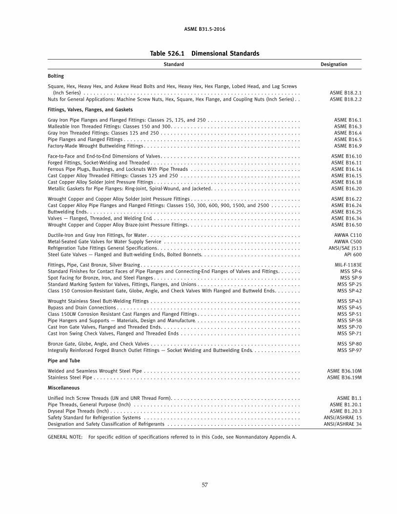
ASME B31.5-2016
Table 526.1 Dimensional Standards
Standard Designation
Bolting
Square, Hex, Heavy Hex, and Askew Head Bolts and Hex, Heavy Hex, Hex Flange, Lobed Head, and Lag Screws(Inch Series) . . . . . . . . . . . . . . . . . . . . . . . . . . . . . . . . . . . . . . . . . . . . . . . . . . . . . . . . . . . . . . . . . ASME B18.2.1
Nuts for General Applications: Machine Screw Nuts, Hex, Square, Hex Flange, and Coupling Nuts (Inch Series) . . ASME B18.2.2
Fittings, Valves, Flanges, and Gaskets
Gray Iron Pipe Flanges and Flanged Fittings: Classes 25, 125, and 250 . . . . . . . . . . . . . . . . . . . . . . . . . . . . ASME B16.1Malleable Iron Threaded Fittings: Classes 150 and 300. . . . . . . . . . . . . . . . . . . . . . . . . . . . . . . . . . . . . . . ASME B16.3Gray Iron Threaded Fittings: Classes 125 and 250 . . . . . . . . . . . . . . . . . . . . . . . . . . . . . . . . . . . . . . . . . . ASME B16.4Pipe Flanges and Flanged Fittings . . . . . . . . . . . . . . . . . . . . . . . . . . . . . . . . . . . . . . . . . . . . . . . . . . . . . ASME B16.5Factory-Made Wrought Buttwelding Fittings . . . . . . . . . . . . . . . . . . . . . . . . . . . . . . . . . . . . . . . . . . . . . . . ASME B16.9
Face-to-Face and End-to-End Dimensions of Valves. . . . . . . . . . . . . . . . . . . . . . . . . . . . . . . . . . . . . . . . . . ASME B16.10Forged Fittings, Socket-Welding and Threaded . . . . . . . . . . . . . . . . . . . . . . . . . . . . . . . . . . . . . . . . . . . . . ASME B16.11Ferrous Pipe Plugs, Bushings, and Locknuts With Pipe Threads . . . . . . . . . . . . . . . . . . . . . . . . . . . . . . . . . ASME B16.14Cast Copper Alloy Threaded Fittings: Classes 125 and 250 . . . . . . . . . . . . . . . . . . . . . . . . . . . . . . . . . . . . ASME B16.15Cast Copper Alloy Solder Joint Pressure Fittings . . . . . . . . . . . . . . . . . . . . . . . . . . . . . . . . . . . . . . . . . . . . ASME B16.18Metallic Gaskets for Pipe Flanges: Ring-Joint, Spiral-Wound, and Jacketed. . . . . . . . . . . . . . . . . . . . . . . . . . . ASME B16.20
Wrought Copper and Copper Alloy Solder Joint Pressure Fittings . . . . . . . . . . . . . . . . . . . . . . . . . . . . . . . . . ASME B16.22Cast Copper Alloy Pipe Flanges and Flanged Fittings: Classes 150, 300, 600, 900, 1500, and 2500 . . . . . . . . . ASME B16.24Buttwelding Ends. . . . . . . . . . . . . . . . . . . . . . . . . . . . . . . . . . . . . . . . . . . . . . . . . . . . . . . . . . . . . . . . ASME B16.25Valves — Flanged, Threaded, and Welding End. . . . . . . . . . . . . . . . . . . . . . . . . . . . . . . . . . . . . . . . . . . . . ASME B16.34Wrought Copper and Copper Alloy Braze-Joint Pressure Fittings. . . . . . . . . . . . . . . . . . . . . . . . . . . . . . . . . . ASME B16.50
Ductile-Iron and Gray Iron Fittings, for Water . . . . . . . . . . . . . . . . . . . . . . . . . . . . . . . . . . . . . . . . . . . . . . AWWA C110Metal-Seated Gate Valves for Water Supply Service . . . . . . . . . . . . . . . . . . . . . . . . . . . . . . . . . . . . . . . . . AWWA C500Refrigeration Tube Fittings General Specifications. . . . . . . . . . . . . . . . . . . . . . . . . . . . . . . . . . . . . . . . . . . ANSI/SAE J513Steel Gate Valves — Flanged and Butt-welding Ends, Bolted Bonnets. . . . . . . . . . . . . . . . . . . . . . . . . . . . . . API 600
Fittings, Pipe, Cast Bronze, Silver Brazing . . . . . . . . . . . . . . . . . . . . . . . . . . . . . . . . . . . . . . . . . . . . . . . . MIL-F-1183EStandard Finishes for Contact Faces of Pipe Flanges and Connecting-End Flanges of Valves and Fittings. . . . . . . MSS SP-6Spot Facing for Bronze, Iron, and Steel Flanges . . . . . . . . . . . . . . . . . . . . . . . . . . . . . . . . . . . . . . . . . . . . MSS SP-9Standard Marking System for Valves, Fittings, Flanges, and Unions . . . . . . . . . . . . . . . . . . . . . . . . . . . . . . . MSS SP-25Class 150 Corrosion-Resistant Gate, Globe, Angle, and Check Valves With Flanged and Buttweld Ends. . . . . . . . MSS SP-42
Wrought Stainless Steel Butt-Welding Fittings . . . . . . . . . . . . . . . . . . . . . . . . . . . . . . . . . . . . . . . . . . . . . MSS SP-43Bypass and Drain Connections . . . . . . . . . . . . . . . . . . . . . . . . . . . . . . . . . . . . . . . . . . . . . . . . . . . . . . . MSS SP-45Class 150LW Corrosion Resistant Cast Flanges and Flanged Fittings . . . . . . . . . . . . . . . . . . . . . . . . . . . . . . . MSS SP-51Pipe Hangers and Supports — Materials, Design and Manufacture. . . . . . . . . . . . . . . . . . . . . . . . . . . . . . . . MSS SP-58Cast Iron Gate Valves, Flanged and Threaded Ends. . . . . . . . . . . . . . . . . . . . . . . . . . . . . . . . . . . . . . . . . . MSS SP-70Cast Iron Swing Check Valves, Flanged and Threaded Ends . . . . . . . . . . . . . . . . . . . . . . . . . . . . . . . . . . . . MSS SP-71
Bronze Gate, Globe, Angle, and Check Valves . . . . . . . . . . . . . . . . . . . . . . . . . . . . . . . . . . . . . . . . . . . . . MSS SP-80Integrally Reinforced Forged Branch Outlet Fittings — Socket Welding and Buttwelding Ends. . . . . . . . . . . . . . . MSS SP-97
Pipe and Tube
Welded and Seamless Wrought Steel Pipe . . . . . . . . . . . . . . . . . . . . . . . . . . . . . . . . . . . . . . . . . . . . . . . ASME B36.10MStainless Steel Pipe . . . . . . . . . . . . . . . . . . . . . . . . . . . . . . . . . . . . . . . . . . . . . . . . . . . . . . . . . . . . . . ASME B36.19M
Miscellaneous
Unified Inch Screw Threads (UN and UNR Thread Form). . . . . . . . . . . . . . . . . . . . . . . . . . . . . . . . . . . . . . . ASME B1.1Pipe Threads, General Purpose (Inch) . . . . . . . . . . . . . . . . . . . . . . . . . . . . . . . . . . . . . . . . . . . . . . . . . . ASME B1.20.1Dryseal Pipe Threads (Inch) . . . . . . . . . . . . . . . . . . . . . . . . . . . . . . . . . . . . . . . . . . . . . . . . . . . . . . . . . ASME B1.20.3Safety Standard for Refrigeration Systems . . . . . . . . . . . . . . . . . . . . . . . . . . . . . . . . . . . . . . . . . . . . . . . ANSI/ASHRAE 15Designation and Safety Classification of Refrigerants . . . . . . . . . . . . . . . . . . . . . . . . . . . . . . . . . . . . . . . . ANSI/ASHRAE 34
GENERAL NOTE: For specific edition of specifications referred to in this Code, see Nonmandatory Appendix A.
57
ASME B31.5-2016
Chapter VFabrication and Assembly
527 WELDING
527.1 Material
527.1.1 Electrodes and Filler Metal. Welding elec-trodes and filler metal, including consumable inserts,shall conform to the requirements of the ASME BPVCode, Section II, Part C. An electrode or filler metalnot conforming to the above may be used provided thewelding procedure specification (WPS) and the weldersand welding operators who follow the WPS have beenqualified as required by ASME Section IX.
Unless otherwise specified by the designer, weldingelectrodes and filler metals used shall comply with thefollowing:
(a) The minimum tensile strength of the filler metalshall equal or exceed the respective minimum tensilestrength of the base metals joined.
(b) If base metals of different minimum tensilestrengths are to be joined, the nominal tensile strengthof the filler metal shall equal or exceed the respectiveminimum tensile strength of the weaker of the two.
(c) The nominal chemical composition of the fillermetal shall be like the nominal chemical compositionof the major alloying elements of the base metal.
(d) If base metals of different nominal chemical com-position are being joined, the nominal chemical compo-sition of the filler metal shall be the same as eitherbase metal or an intermediate composition, except asspecified below for austenitic steels joined to ferriticsteels.
(e) When austenitic steels are joined to ferritic steels,the filler metal shall have an austenitic structure.
(f) For nonferrous metals, the filler metal shall be thatrecommended by the manufacturer of the nonferrousmetal or by industry associations for that metal.
(g) Where impact testing of the WPS is required bysection 527, the filler metal used shall be of a classifica-tion in the applicable ASME Section II, Part C filler metalspecification that exhibits absorbed energy (ft-lb) equalto or greater than that required for the base metals tobe welded at a temperature equal to or lower than thelowest service temperature for the base metal.
527.1.2 Backing Rings. The use of backing rings isnot mandatory; however, when used, they shall conformto the following requirements (see also para. 511.2):
(a) Ferrous Rings. Backing rings shall be made frommaterial of good weldable quality, and the sulfur content
58
shall not exceed 0.05%. The backing ring material shouldpreferably be of the same chemical composition as theparts to be joined.
Backing rings may be of the continuous machined, orsplit band type. Some acceptable split types are shownin Fig. 527.1.2.
(b) Nonferrous and Nonmetallic Rings. Backing rings ofnonferrous or nonmetallic materials may be used pro-vided they have no effect on the weld or the containedfluid. The satisfactory use of such materials shall bedetermined by the qualification of the weldingprocedure.
527.2 Preparation
527.2.1 Butt Welds(a) End Preparation
(1) Oxygen or arc cutting is acceptable only if thecut is reasonably smooth and true and all slag is cleanedfrom the flame cut surfaces. Discoloration that mayremain on the flame cut surface is not considered to bedetrimental oxidation.
(2) Buttwelding end preparation dimensions con-tained in ASME B16.25 or any other angles that meetthe requirements of the welding procedure are accept-able. (For convenience, the basic bevel angles taken fromASME B16.25 are shown in Fig. 527.2.1-1.)
(3) If piping component ends are bored for fittingbacking rings, such boring shall not result in a finishedwall thickness after welding less than the minimumdesign thickness plus corrosion and erosion allowances.Where necessary, weld metal may be deposited on theinside of the piping component to provide sufficientmaterial for machining to ensure satisfactory seating ofthe rings.
(4) If the piping ends are upset, they may be boredto allow for a completely recessed backing ring, pro-vided the remaining net thickness of the finished endsis not less than the minimum design thickness plus cor-rosion and erosion allowance.
(b) Cleaning. Surfaces for welding shall be clean andshall be free from rust, scale, or other material that isdetrimental to welding. Galvanizing must be removedfrom the weld zone of galvanized carbon steel.
(c) Alignment. Misalignment of the inside surfaces ofpiping components to be joined by butt welding mayresult from out-of-roundness, outside diameter toler-ance, wall thickness tolerance, or from the inclusion in
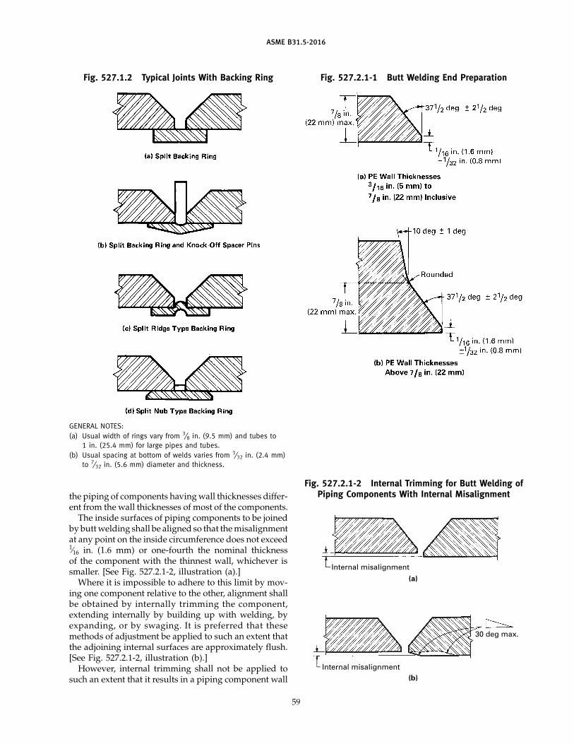
ASME B31.5-2016
Fig. 527.1.2 Typical Joints With Backing Ring
GENERAL NOTES:(a) Usual width of rings vary from 3⁄8 in. (9.5 mm) and tubes to
1 in. (25.4 mm) for large pipes and tubes.(b) Usual spacing at bottom of welds varies from 3⁄32 in. (2.4 mm)
to 7⁄32 in. (5.6 mm) diameter and thickness.
the piping of components having wall thicknesses differ-ent from the wall thicknesses of most of the components.
The inside surfaces of piping components to be joinedby butt welding shall be aligned so that the misalignmentat any point on the inside circumference does not exceed1⁄16 in. (1.6 mm) or one-fourth the nominal thicknessof the component with the thinnest wall, whichever issmaller. [See Fig. 527.2.1-2, illustration (a).]
Where it is impossible to adhere to this limit by mov-ing one component relative to the other, alignment shallbe obtained by internally trimming the component,extending internally by building up with welding, byexpanding, or by swaging. It is preferred that thesemethods of adjustment be applied to such an extent thatthe adjoining internal surfaces are approximately flush.[See Fig. 527.2.1-2, illustration (b).]
However, internal trimming shall not be applied tosuch an extent that it results in a piping component wall
59
Fig. 527.2.1-1 Butt Welding End Preparation
Fig. 527.2.1-2 Internal Trimming for Butt Welding ofPiping Components With Internal Misalignment
(a)
(b)
Internal misalignment
30 deg max.
Internal misalignment
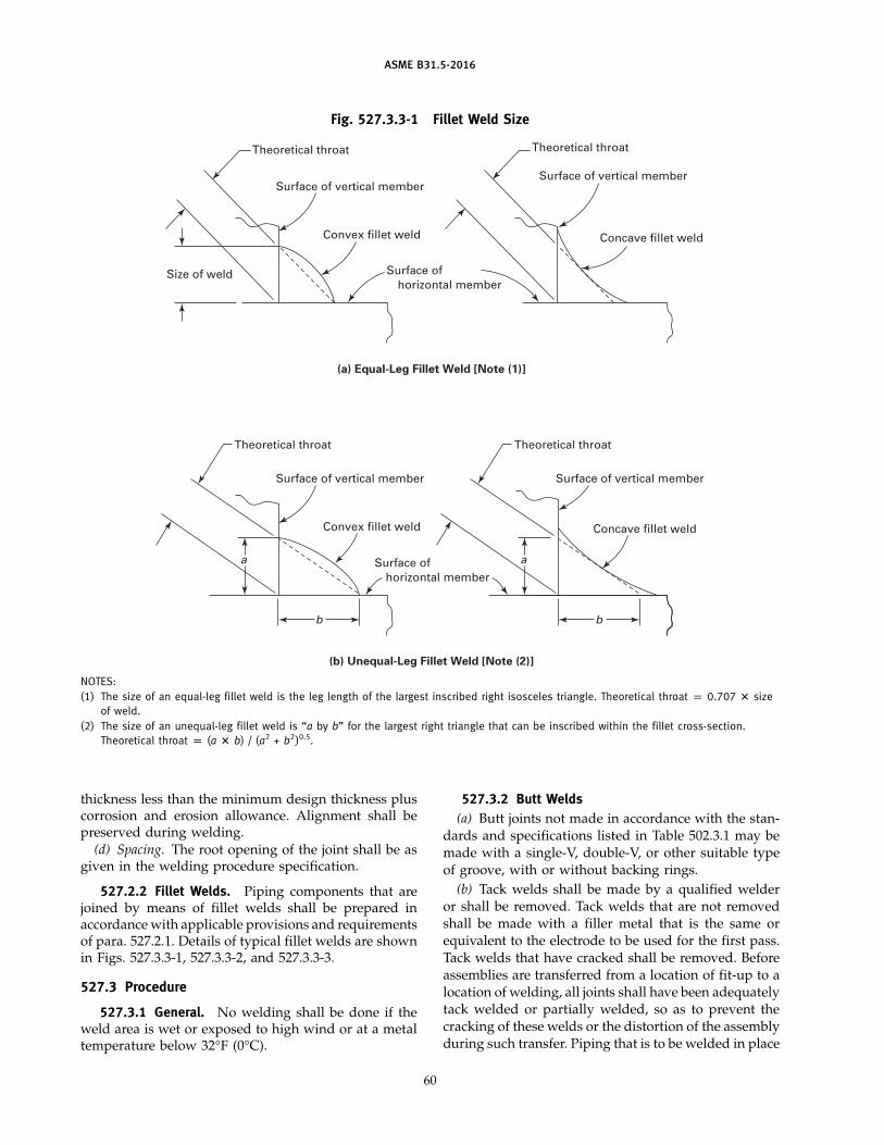
ASME B31.5-2016
Fig. 527.3.3-1 Fillet Weld Size
Theoretical throat Theoretical throat
Surface of vertical memberSurface of vertical member
Convex fillet weld
(a) Equal-Leg Fillet Weld [Note (1)]
Size of weld
Concave fillet weld
Surface of horizontal member
(b) Unequal-Leg Fillet Weld [Note (2)]
Theoretical throat
Surface of vertical member
Convex fillet weld
b
a Surface of horizontal member
Theoretical throat
Surface of vertical member
Concave fillet weld
b
a
NOTES:(1) The size of an equal-leg fillet weld is the leg length of the largest inscribed right isosceles triangle. Theoretical throat p 0.707 � size
of weld.(2) The size of an unequal-leg fillet weld is “a by b” for the largest right triangle that can be inscribed within the fillet cross-section.
Theoretical throat p (a � b) / (a2 + b2)0.5.
thickness less than the minimum design thickness pluscorrosion and erosion allowance. Alignment shall bepreserved during welding.
(d) Spacing. The root opening of the joint shall be asgiven in the welding procedure specification.
527.2.2 Fillet Welds. Piping components that arejoined by means of fillet welds shall be prepared inaccordance with applicable provisions and requirementsof para. 527.2.1. Details of typical fillet welds are shownin Figs. 527.3.3-1, 527.3.3-2, and 527.3.3-3.
527.3 Procedure
527.3.1 General. No welding shall be done if theweld area is wet or exposed to high wind or at a metaltemperature below 32°F (0°C).
60
527.3.2 Butt Welds(a) Butt joints not made in accordance with the stan-
dards and specifications listed in Table 502.3.1 may bemade with a single-V, double-V, or other suitable typeof groove, with or without backing rings.
(b) Tack welds shall be made by a qualified welderor shall be removed. Tack welds that are not removedshall be made with a filler metal that is the same orequivalent to the electrode to be used for the first pass.Tack welds that have cracked shall be removed. Beforeassemblies are transferred from a location of fit-up to alocation of welding, all joints shall have been adequatelytack welded or partially welded, so as to prevent thecracking of these welds or the distortion of the assemblyduring such transfer. Piping that is to be welded in place
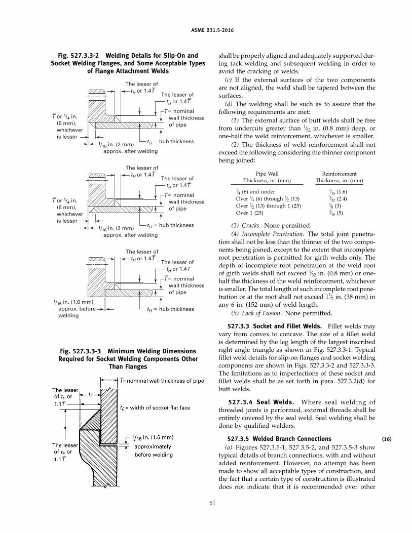
ASME B31.5-2016
Fig. 527.3.3-2 Welding Details for Slip-On andSocket Welding Flanges, and Some Acceptable Types
of Flange Attachment Welds
T_ or 1/4 in.
(6 mm), whichever is lesser
T_ or 1/4 in.
(6 mm), whichever is lesser
The lesser of tH or 1.4T
_
tH � hub thickness1/16 in. (2 mm) approx. after welding
The lesser of tH or 1.4T
_
The lesser of tH or 1.4T
_
T_ � nominal
wall thickness of pipe
tH � hub thickness1/16 in. (2 mm) approx. after welding
The lesser of tH or 1.4T
_
T_ � nominal
wall thickness of pipe
The lesser of tH or 1.4T
_
T_ � nominal
wall thickness of pipe
The lesser of tH or 1.4T
_
tH � hub thickness
1/16 in. (1.6 mm) approx. before welding
Fig. 527.3.3-3 Minimum Welding DimensionsRequired for Socket Welding Components Other
Than Flanges
61
shall be properly aligned and adequately supported dur-ing tack welding and subsequent welding in order toavoid the cracking of welds.
(c) If the external surfaces of the two componentsare not aligned, the weld shall be tapered between thesurfaces.
(d) The welding shall be such as to assure that thefollowing requirements are met:
(1) The external surface of butt welds shall be freefrom undercuts greater than 1⁄32 in. (0.8 mm) deep, orone-half the weld reinforcement, whichever is smaller.
(2) The thickness of weld reinforcement shall notexceed the following considering the thinner componentbeing joined:
Pipe Wall ReinforcementThickness, in. (mm) Thickness, in. (mm)
1⁄4 (6) and under 1⁄16 (1.6)Over 1⁄4 (6) through 1⁄2 (13) 3⁄32 (2.4)Over 1⁄2 (13) through 1 (25) 1⁄8 (3)Over 1 (25) 3⁄16 (5)
(3) Cracks. None permitted.(4) Incomplete Penetration. The total joint penetra-
tion shall not be less than the thinner of the two compo-nents being joined, except to the extent that incompleteroot penetration is permitted for girth welds only. Thedepth of incomplete root penetration at the weld rootof girth welds shall not exceed 1⁄32 in. (0.8 mm) or one-half the thickness of the weld reinforcement, whicheveris smaller. The total length of such incomplete root pene-tration or at the root shall not exceed 11⁄2 in. (38 mm) inany 6 in. (152 mm) of weld length.
(5) Lack of Fusion. None permitted.
527.3.3 Socket and Fillet Welds. Fillet welds mayvary from convex to concave. The size of a fillet weldis determined by the leg length of the largest inscribedright angle triangle as shown in Fig. 527.3.3-1. Typicalfillet weld details for slip-on flanges and socket weldingcomponents are shown in Figs. 527.3.3-2 and 527.3.3-3.The limitations as to imperfections of these socket andfillet welds shall be as set forth in para. 527.3.2(d) forbutt welds.
527.3.4 Seal Welds. Where seal welding ofthreaded joints is performed, external threads shall beentirely covered by the seal weld. Seal welding shall bedone by qualified welders.
527.3.5 Welded Branch Connections(a) Figures 527.3.5-1, 527.3.5-2, and 527.3.5-3 show
typical details of branch connections, with and withoutadded reinforcement. However, no attempt has beenmade to show all acceptable types of construction, andthe fact that a certain type of construction is illustrateddoes not indicate that it is recommended over other
(16)
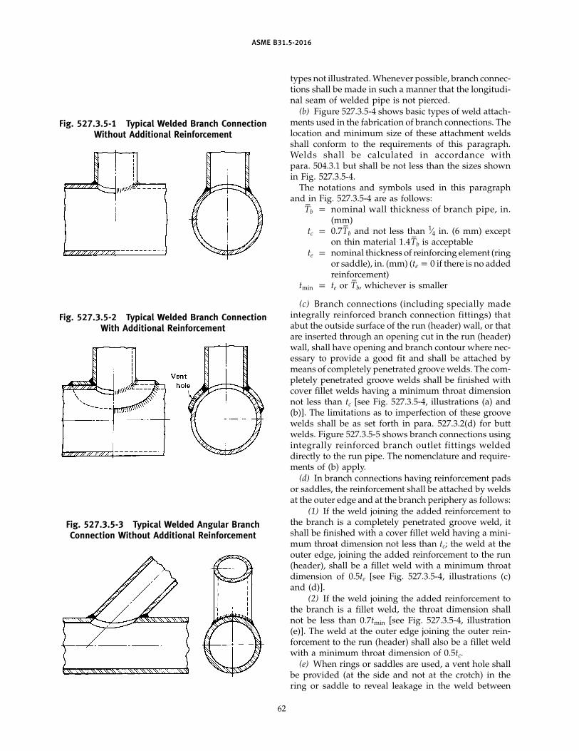
ASME B31.5-2016
Fig. 527.3.5-1 Typical Welded Branch ConnectionWithout Additional Reinforcement
Fig. 527.3.5-2 Typical Welded Branch ConnectionWith Additional Reinforcement
Fig. 527.3.5-3 Typical Welded Angular BranchConnection Without Additional Reinforcement
62
types not illustrated. Whenever possible, branch connec-tions shall be made in such a manner that the longitudi-nal seam of welded pipe is not pierced.
(b) Figure 527.3.5-4 shows basic types of weld attach-ments used in the fabrication of branch connections. Thelocation and minimum size of these attachment weldsshall conform to the requirements of this paragraph.Welds shall be calculated in accordance withpara. 504.3.1 but shall be not less than the sizes shownin Fig. 527.3.5-4.
The notations and symbols used in this paragraphand in Fig. 527.3.5-4 are as follows:
T–
b p nominal wall thickness of branch pipe, in.(mm)
tc p 0.7T–
b and not less than 1⁄4 in. (6 mm) excepton thin material 1.4T
–b is acceptable
te p nominal thickness of reinforcing element (ringor saddle), in. (mm) (te p 0 if there is no addedreinforcement)
tmin p te or T–
b, whichever is smaller
(c) Branch connections (including specially madeintegrally reinforced branch connection fittings) thatabut the outside surface of the run (header) wall, or thatare inserted through an opening cut in the run (header)wall, shall have opening and branch contour where nec-essary to provide a good fit and shall be attached bymeans of completely penetrated groove welds. The com-pletely penetrated groove welds shall be finished withcover fillet welds having a minimum throat dimensionnot less than tc [see Fig. 527.3.5-4, illustrations (a) and(b)]. The limitations as to imperfection of these groovewelds shall be as set forth in para. 527.3.2(d) for buttwelds. Figure 527.3.5-5 shows branch connections usingintegrally reinforced branch outlet fittings weldeddirectly to the run pipe. The nomenclature and require-ments of (b) apply.
(d) In branch connections having reinforcement padsor saddles, the reinforcement shall be attached by weldsat the outer edge and at the branch periphery as follows:
(1) If the weld joining the added reinforcement tothe branch is a completely penetrated groove weld, itshall be finished with a cover fillet weld having a mini-mum throat dimension not less than tc; the weld at theouter edge, joining the added reinforcement to the run(header), shall be a fillet weld with a minimum throatdimension of 0.5te [see Fig. 527.3.5-4, illustrations (c)and (d)].
(2) If the weld joining the added reinforcement tothe branch is a fillet weld, the throat dimension shallnot be less than 0.7tmin [see Fig. 527.3.5-4, illustration(e)]. The weld at the outer edge joining the outer rein-forcement to the run (header) shall also be a fillet weldwith a minimum throat dimension of 0.5tc.
(e) When rings or saddles are used, a vent hole shallbe provided (at the side and not at the crotch) in thering or saddle to reveal leakage in the weld between
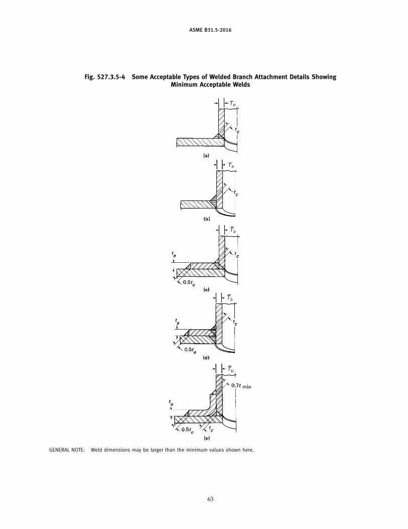
ASME B31.5-2016
Fig. 527.3.5-4 Some Acceptable Types of Welded Branch Attachment Details ShowingMinimum Acceptable Welds
GENERAL NOTE: Weld dimensions may be larger than the minimum values shown here.
63
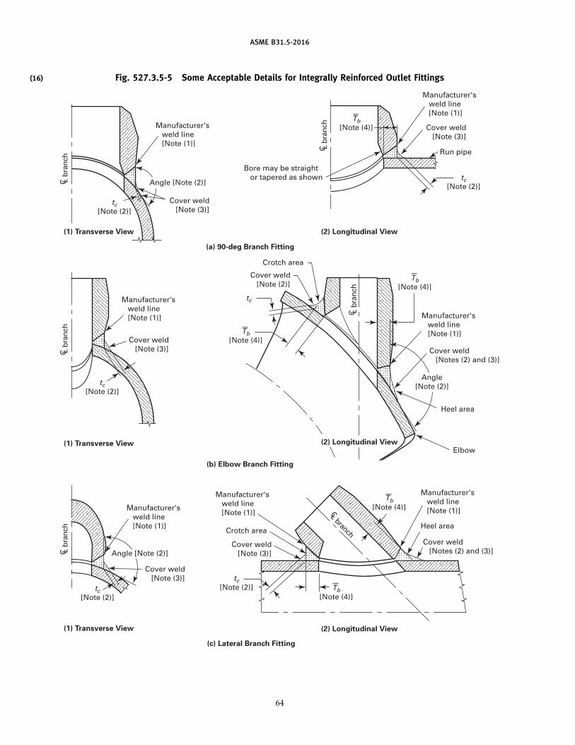
(16)
ASME B31.5-2016
Fig. 527.3.5-5 Some Acceptable Details for Integrally Reinforced Outlet Fittings
Manufacturer's weld line [Note (1)]
Bore may be straight or tapered as shown
C L b
ranc
h C L
bra
nch
C L b
ranc
h
CL branch
C L b
ranc
h
C L b
ranc
h
Manufacturer's weld line [Note (1)]
Manufacturer's weld line [Note (1)]
Manufacturer's weld line [Note (1)]
Manufacturer's weld line [Note (1)]
Manufacturer's weld line [Note (1)]
Manufacturer's weld line [Note (1)]
(1) Transverse View
(a) 90-deg Branch Fitting
(b) Elbow Branch Fitting
(c) Lateral Branch Fitting
(1) Transverse View
(1) Transverse View
(2) Longitudinal View
(2) Longitudinal View
(2) Longitudinal View
Cover weld [Note (3)]
Cover weld [Note (3)]
Angle [Note (2)]
Cover weld [Note (3)]
Cover weld [Note (3)]
Run pipe
Cover weld [Notes (2) and (3)]
Heel area
Heel area
Elbow
Cover weld [Notes (2) and (3)]
Cover weld [Note (2)]
Crotch area
Cover weld [Note (3)]
Crotch area
tc [Note (2)]
tc [Note (2)]
tc [Note (2)]
Tb[Note (4)]
tc
Angle [Note (2)]
tc [Note (2)]
Angle [Note (2)]
tc [Note (2)]
Tb[Note (4)]
Tb[Note (4)]
Tb[Note (4)]
Tb[Note (4)]
64
ASME B31.5-2016
Fig. 527.3.5-5 Some Acceptable Details for Integrally Reinforced Outlet Fittings (Cont’d)
GENERAL NOTES:(a) Welds shall be in accordance with para. 527.3.5.(b) Weld attachment details for branch fittings that do not match the schedule or weight designation of the run pipe as defined by MSS
SP-97 Table 1 shall be designed to meet the requirements in paras. 504.3.1 and 504.7.(c) The stress intensification factors as required by para. 519.3.6, for the fittings represented by drawings (b-1), (b-2), (c-1), and (c-2),
should be obtained from the fitting manufacturer.
NOTES:(1) When the fitting manufacturer has not provided a visible scribe line on the branch fitting, the weld line shall be the edge of the first
bevel on the branch fitting adjacent to the run pipe.(2) The minimum cover weld throat thickness, tc, applies when the angle between the branch fitting groove weld face and the run pipe
surface is less than 135 deg. For areas where the angle between the groove weld face and the run pipe surface is 135 deg or greater,the cover weld may transition to nothing.
(3) Cover weld shall provide a smooth transition to the run pipe.(4) Tb shall be measured at the longitudinal centerline of the branch fitting. When Tb in the crotch area does not equal Tb in the heel area,
the thicker of the two shall govern in determining the heat treatment in accordance with para. 531.
branch and main run and to provide venting duringwelding and heat treating operations. Rings or saddlesmay be made in more than the one piece if the jointsbetween the pieces have adequate strength and if eachpiece is provided with a vent hole. A good fit shall beprovided between reinforcing rings or saddles and theparts to which they are attached.
527.3.6 Welded Flat Plate Closures.Figures 527.3.6-1 and 527.3.6-2 show acceptable and
unacceptable welds for flat plate closures in pipe. Seepara. 504.4.2 for nomenclature.
527.3.7 Heat Treatment for Welds. Heat treatmentof welds shall be in accordance with section 531.
527.4 Responsibility
Each employer is responsible for(a) the welding and brazing performed by personnel
of his organization(b) conducting the qualification tests required to qual-
ify the Welding Procedure Specifications (WPSs) andBrazing Procedure Specifications (BPSs) used by person-nel in his organization, except as provided inpara. 527.4.3
(c) conducting the qualification tests required to qual-ify the welders and welding operators, except as pro-vided in para. 527.4.4
527.4.1 Qualification Requirements. WPSs andBPSs to be followed in production welding shall be pre-pared and qualified. Welders, brazers, and operatorsshall be qualified as required by Section IX of the ASMEBoiler and Pressure Vessel Code, except as modified inparas. 527.4.2, 527.4.3, and 527.4.4.
527.4.2 Standard Welding Procedures. StandardWelding Procedure Specifications (SWPSs) published bythe American Welding Society and listed in Appendix Eof ASME Section IX are permitted within the limitationsestablished by Article V of ASME Section IX. Before
65
being used, the employer shall either qualify one welderfollowing each SWPS or make demonstration welds asprovided by Section IX, Article V.
527.4.3 Procedure Qualification by Others. In orderto avoid duplication of effort and subject to the approvalof the owner, WPSs and BPSs qualified by a technicallycompetent group or agency may be used provided thefollowing are met:
(a) The WPS or BPS meet the requirements of ASMESection IX and any additional qualification requirementsof this Code.
(b) The employer has qualified at least one welder orwelding operator following each WPS or BPS.
(c) The employer’s business name shall be shown oneach WPS or BPS and on each qualification record. Inaddition, qualification records shall be signed and datedby the employer, thereby accepting responsibility for thequalifications performed by others.
527.4.4 Performance Qualification by Others. Inorder to avoid duplication of effort and subject to theapproval of the owner, an employer may accept theperformance qualification of a welder, brazer, or opera-tor made by a previous employer. This acceptance islimited to performance qualifications that were madeon pipe or tube test coupons. The new employer shallhave the WPS or BPS that was followed during qualifica-tion or an equivalent WPS or BPS that is within thelimits of the essential variables set forth in ASMESection IX. An employer accepting such qualificationtests shall obtain a copy of the performance qualificationtest record from the previous employer. The record shallshow the name of the employer by whom the welder,brazer, or operator was qualified and the date of thatqualification. A record shall be available showing useof each process at no less than 6-mo intervals from thedate of qualification with that process to the date thatthe qualification record is transferred to the newemployer. The new employer’s business name shall be
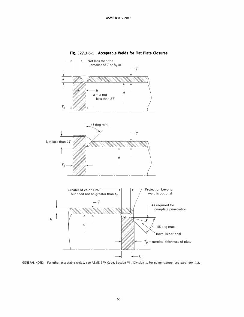
ASME B31.5-2016
Fig. 527.3.6-1 Acceptable Welds for Flat Plate Closures
Not less than the smaller of T
_ or 1/4 in.
ba � b not less than 2T
_
Not less than 2T_
a
d
45 deg min.
d
T_
d
T_
T_ p � nominal thickness of plate
tm
Bevel is optional
45 deg max.
As required for complete penetration
Projection beyond weld is optional
Greater of 2tr or 1.25T_
but need not be greater than tm
tr
T_
T_ p
T_ p
GENERAL NOTE: For other acceptable welds, see ASME BPV Code, Section VIII, Division 1. For nomenclature, see para. 504.4.2.
66
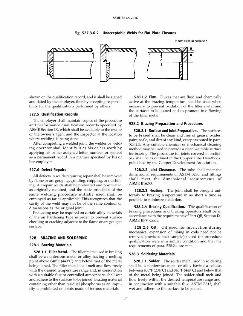
ASME B31.5-2016
Fig. 527.3.6-2 Unacceptable Welds for Flat Plate Closures
shown on the qualification record, and it shall be signedand dated by the employer, thereby accepting responsi-bility for the qualifications performed by others.
527.5 Qualification Records
The employer shall maintain copies of the procedureand performance qualification records specified byASME Section IX, which shall be available to the owneror the owner’s agent and the Inspector at the locationwhere welding is being done.
After completing a welded joint, the welder or weld-ing operator shall identify it as his or her work byapplying his or her assigned letter, number, or symbolas a permanent record in a manner specified by his orher employer.
527.6 Defect Repairs
All defects in welds requiring repair shall be removedby flame or arc gouging, grinding, chipping, or machin-ing. All repair welds shall be preheated and postheatedas originally required, and the basic principles of thesame welding procedure initially used shall beemployed as far as applicable. This recognizes that thecavity of the weld may not be of the same contour ordimensions as the original joint.
Preheating may be required on certain alloy materialsof the air hardening type in order to prevent surfacechecking or cracking adjacent to the flame or arc gougedsurface.
528 BRAZING AND SOLDERING
528.1 Brazing Materials
528.1.1 Filler Metal. The filler metal used in brazingshall be a nonferrous metal or alloy having a meltingpoint above 840°F (449°C) and below that of the metalbeing joined. The filler metal shall melt and flow freelywith the desired temperature range and, in conjunctionwith a suitable flux or controlled atmosphere, shall wetand adhere to the surfaces to be joined. Brazing materialcontaining other than residual phosphorus as an impu-rity is prohibited on joints made of ferrous materials.
67
528.1.2 Flux. Fluxes that are fluid and chemicallyactive at the brazing temperature shall be used whennecessary to prevent oxidation of the filler metal andthe surfaces to be joined and to promote free flowingof the filler metal.
528.2 Brazing Preparation and Procedures
528.2.1 Surface and Joint Preparation. The surfacesto be brazed shall be clean and free of grease, oxides,paint, scale, and dirt of any kind, except as noted in para.528.2.5. Any suitable chemical or mechanical cleaningmethod may be used to provide a clean wettable surfacefor brazing. The procedure for joints covered in section517 shall be as outlined in the Copper Tube Handbook,published by the Copper Development Association.
528.2.2 Joint Clearance. The tube shall meet thedimensional requirements of ASTM B280, and fittingsshall meet the dimensional requirements ofASME B16.50.
528.2.3 Heating. The joint shall be brought uni-formly to brazing temperature in as short a time aspossible to minimize oxidation.
528.2.4 Brazing Qualification. The qualification ofbrazing procedures and brazing operators shall be inaccordance with the requirements of Part QB, Section IX,ASME BPV Code.
528.2.5 Oil. Oil used for lubrication duringmechanical expansion of tubing in coils need not beremoved provided that sample(s) used for procedurequalification were in a similar condition and that therequirements of para. 528.2.4 are met.
528.3 Soldering Materials
528.3.1 Solder. The solder metal used in solderingshall be a nonferrous metal or alloy having a solidusbetween 400°F (204°C) and 840°F (449°C) and below thatof the metal being joined. The solder shall melt andflow freely within the desired temperature range and,in conjunction with a suitable flux, ASTM B813, shallwet and adhere to the surface to be joined.
ASME B31.5-2016
528.3.2 Flux. Fluxes that are fluid and chemicallyactive at the soldering temperature shall be used toprevent oxidation of the solder or filler metal and thesurfaces to be joined and to promote the free flowingof the solder.
528.4 Soldering Preparation and Procedure
528.4.1 Surface Preparation. The surfaces to be sol-dered shall be clean and free from grease, oxides, paint,scale, and dirt of any kind. Any suitable chemical ormechanical cleaning method may be used to provide aclean wettable surface for soldering.
528.4.2 Joint Clearance. The tube shall meet thedimensional requirements of ASTM B280, and fittingsshall meet the dimensional requirements ofASME B16.18 or ASME B16.22, as applicable.
528.4.3 Heating. The joint shall be brought to sol-dering temperature in as short a time as possible tominimize oxidation without localized underheating oroverheating.
528.4.4 Procedure. Solderers shall follow the proce-dure as outlined in ASTM B828.
529 BENDING — HOT AND COLD
529.1 Radii of Bends
Pipe and tube may be bent to any radius that willresult in a bend surface free of cracks and substantiallyfree of buckles. Out-of-roundness and minimum fin-ished thickness of bend shall be such that design require-ments of section 504 are met. This shall not prohibit theuse of bends designed as creased or corrugated.
529.2 Procedure
Pipe and tube may be bent by any hot or cold methodpermissible by radii and material characteristics of thesizes being bent. Bending shall be done within a temper-ature range consistent with material characteristics andend use. Postheat treatment may be used to achieve thisresult.
529.3 Heat Treatment
Heat treatment shall be in accordance withparas. 531.1, 531.3.2, 531.3.3, and 531.3.5.
530 FORMING
530.1 Procedure
Piping components may be formed by any suitablemethod, including hot or cold pressing, rolling, forging,hammering, spinning, or drawing. Forming shall bedone within a temperature range consistent with mate-rial characteristics and end use. Postheat treatment maybe used to achieve this result.
68
530.2 Heat Treatment
Heat treatment shall be in accordance withparas. 531.1, 531.3.2, 531.3.3, and 531.3.5.
531 HEAT TREATMENT
531.1 Heating and Cooling Method
Heat treatment may be accomplished by a suitableheating method that will provide the required metaltemperature, metal temperature uniformity, and tem-perature control, such as an enclosed furnace, local fuelfiring, electric resistance, or electric induction. Coolingmay be accomplished in a furnace, in air, with the aidof local thermal control, with the application of heat orinsulation, or in any other manner required to achievethe desired cooling rate.
531.2 Preheating
531.2.1 Unless otherwise specified in the qualifiedprocedure specification, preheating for welds in materi-als shall be as stipulated in Table 531.2.1. (See Section IX,ASME BPV Code, for P-Numbers of materials.)
531.2.2 When welding dissimilar metals havingdifferent preheat requirements, the preheat temperatureshall be that established in the welding procedurespecification.
531.2.3 The preheat temperature shall be checkedby use of temperature indicating crayons, thermocouplepyrometers, or other suitable methods to ensure thatthe required preheat temperature is obtained prior toand maintained during the welding operation.
531.3 Postheat Treatment
531.3.1 Unless other postheat treatment is stipu-lated in the welding procedure to meet the requirementsof para. 531.3.2, post-heat treatment for the welds (exceptseal welds of threaded joints for P-Nos. 1 and 3 materials)shall be as stipulated in Table 531.2.1. Seal welds ofthreaded joints for P-Nos. 1 and 3 materials do notrequire postheat treatment.
531.3.2 Postheat treatment shall be performed asnecessary to restore physical property requirements(such as strength, ductility, and corrosion resistance, ora combination thereof) with respect to material design,and end use requirements. Physical property require-ments shall determine the treatment to be performed,such as stress relief, anneal, or normalize.
531.3.3 The heating method selected for restora-tion of physical properties desired for parts of anyassembly shall be such as will accomplish this resultwithout adversely affecting other components. Heatinga fabricated assembly as a complete unit is usually desir-able. However, the size or shape of the unit or the adverse
ASME B31.5-2016
effect of a desired heat treatment on one or more compo-nents where dissimilar materials are involved may dic-tate alternative procedures such as heating a section ofthe assembly before the attachment of others, or localcircumferential band heating of welded joints in accor-dance with this section. The hardness limitations ofTable 531.2.1 are mandatory regardless of the heat treat-ment used.
531.3.4 Postheat treatment of welded jointsbetween dissimilar metals having different postheatrequirements shall be established in the welding proce-dure specification.
531.3.5 Postheat treatment temperatures shall bechecked by the use of thermocouple pyrometers or othersuitable equipment to assure that the desired treatmentcycle has been accomplished.
531.3.6 If welding is interrupted before completedand allowed to cool prior to postheat treatment, ade-quate heat treatment or controlled rate of cooling shallbe effected to assure that no detrimental effect to thework shall result.
531.3.7 Postheat treatment of welds shall be com-patible with the analysis of the base materials beingjoined and the weld deposit. Postheat treatment ofwelded joints shall be established in the welding proce-dure specification.
531.3.8 Where Table 531.2.1 indicates thickness asa factor in determining the requirement for post-heattreatment, nominal pipe wall thickness of the thickerpipe of the governing material that governs the weldsize is intended. However, for lugs, supports, or otherexternal nonpressure-containing attachments, the throatthickness of the attachment welds shall govern for thosewelds.
531.3.9 Local Postheat Treatment(a) Local postheat treatment of welded joints shall
require the entire band to be brought up to uniformtemperature over the circumference of the heated pipesection with a gradual diminishing of temperature out-ward from the band.
(b) When local heat treating a circumferential weld,the minimum width of the band centered on the weldshall be the larger of the following:
(1) twice the width of the weld reinforcement(2) width of weld reinforcement plus 2 in. (51 mm)
(c) When local heat treating welded branch connec-tions or other attachments, a circumferential band of thepipe to which the branch or attachment is welded shallbe heated to the desired temperature. The width of thisband shall extend at least 1 in. (25 mm) beyond the weldjoining the branch or attachment to the pipe.
69
535 ASSEMBLY
535.1 General
The assembly of the various piping components,whether done in a shop or as field erection, shall bedone so that the completely erected piping conformswith all requirements of this Code and with the specifiedrequirements of the engineering design.
535.2 Bolting Procedure
535.2.1 All flanged joints shall be fitted up so thatthe gasket contact faces bear uniformly on the gasket.The joints shall then be progressively tightened in adiametrically staggered pattern.
535.2.2 In bolting gasketed flanged joints, the gas-ket shall be properly compressed in accordance with thedesign principle applicable to the type of gasket used.
535.2.3 Steel-to-cast-iron flanged joints shall beassembled with care to prevent damage to the cast-ironflange (see paras. 508.3 and 508.5).
535.2.4 Bolt threads shall extend completelythrough the mating nut.
535.2.5 In refacing flanges, dimensions must notbe reduced below those shown in ASME B16.5.
535.3 Threaded Piping
535.3.1 Threaded joints that are to be seal weldedshall be made up without any thread compound.
535.3.2 Any compound used in threaded jointsshall be suitable for the service conditions and shall notreact unfavorably with the service fluid.
535.3.3 Threaded joints in ferrous metal pipe shallconform to ASME B1.20.1. Exposed threads should becoated to inhibit corrosion (see section 514).
535.3.4 Threaded joints in copper or brass pipe ofstandard size shall conform to ASME B16.15.
535.3.5 All threaded joints shall be made up tight.Backing off for alignment is not permitted.
535.4 Welded Joints
All welded joints shall be assembled in accordancewith section 527.
535.5 Brazed Sleeve Joints
All brazed sleeve joints shall be assembled in accor-dance with paras. 528.1 through 528.2.
535.6 Soldered Sleeve Joints
All soldered sleeve joints shall be assembled in accor-dance with paras. 528.3 and 528.4.
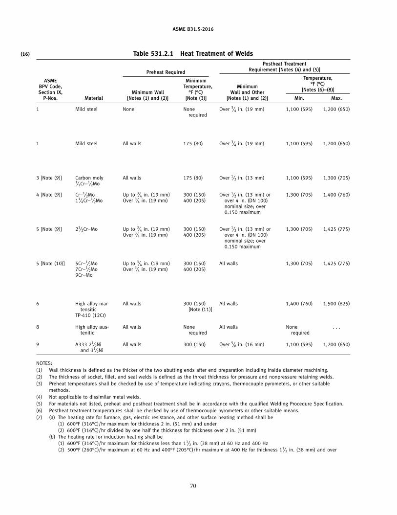
(16)
ASME B31.5-2016
Table 531.2.1 Heat Treatment of WeldsPostheat Treatment
Requirement [Notes (4) and (5)]Preheat RequiredTemperature,ASME Minimum
°F (°C)BPV Code, Temperature, Minimum[Notes (6)–(8)]Section IX, Minimum Wall °F (°C) Wall and Other
P-Nos. Material [Notes (1) and (2)] [Note (3)] [Notes (1) and (2)] Min. Max.
1 Mild steel None None Over 3⁄4 in. (19 mm) 1,100 (595) 1,200 (650)required
1 Mild steel All walls 175 (80) Over 3⁄4 in. (19 mm) 1,100 (595) 1,200 (650)
3 [Note (9)] Carbon moly All walls 175 (80) Over 1⁄2 in. (13 mm) 1,100 (595) 1,300 (705)1⁄2Cr–1⁄2Mo
4 [Note (9)] Cr–1⁄2Mo Up to 3⁄4 in. (19 mm) 300 (150) Over 1⁄2 in. (13 mm) or 1,300 (705) 1,400 (760)11⁄4Cr–1⁄2Mo Over 3⁄4 in. (19 mm) 400 (205) over 4 in. (DN 100)
nominal size; over0.150 maximum
5 [Note (9)] 21⁄2Cr–Mo Up to 3⁄4 in. (19 mm) 300 (150) Over 1⁄2 in. (13 mm) or 1,300 (705) 1,425 (775)Over 3⁄4 in. (19 mm) 400 (205) over 4 in. (DN 100)
nominal size; over0.150 maximum
5 [Note (10)] 5Cr–1⁄2Mo Up to 3⁄4 in. (19 mm) 300 (150) All walls 1,300 (705) 1,425 (775)7Cr–1⁄2Mo Over 3⁄4 in. (19 mm) 400 (205)9Cr–Mo
6 High alloy mar- All walls 300 (150) All walls 1,400 (760) 1,500 (825)tensitic [Note (11)]
TP-410 (12Cr)
8 High alloy aus- All walls None All walls None . . .tenitic required required
9 A333 21⁄2Ni All walls 300 (150) Over 5⁄8 in. (16 mm) 1,100 (595) 1,200 (650)and 31⁄2Ni
NOTES:(1) Wall thickness is defined as the thicker of the two abutting ends after end preparation including inside diameter machining.(2) The thickness of socket, fillet, and seal welds is defined as the throat thickness for pressure and nonpressure retaining welds.(3) Preheat temperatures shall be checked by use of temperature indicating crayons, thermocouple pyrometers, or other suitable
methods.(4) Not applicable to dissimilar metal welds.(5) For materials not listed, preheat and postheat treatment shall be in accordance with the qualified Welding Procedure Specification.(6) Postheat treatment temperatures shall be checked by use of thermocouple pyrometers or other suitable means.(7) (a) The heating rate for furnace, gas, electric resistance, and other surface heating method shall be
(1) 600°F (316°C)/hr maximum for thickness 2 in. (51 mm) and under(2) 600°F (316°C)/hr divided by one half the thickness for thickness over 2 in. (51 mm)
(b) The heating rate for induction heating shall be(1) 600°F (316°C)/hr maximum for thickness less than 11⁄2 in. (38 mm) at 60 Hz and 400 Hz(2) 500°F (260°C)/hr maximum at 60 Hz and 400°F (205°C)/hr maximum at 400 Hz for thickness 11⁄2 in. (38 mm) and over
70
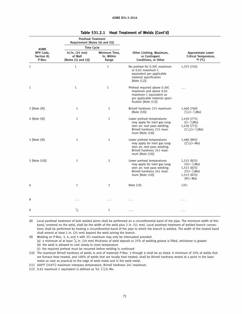
ASME B31.5-2016
Table 531.2.1 Heat Treatment of Welds (Cont’d)Postheat Treatment
Requirement [Notes (4) and (5)]
Time CycleASMEBPV Code, hr/in. (25 mm) Minimum Time, Other Limiting, Maximum, Approximate LowerSection IX, of Wall hr, Within or Contingent Critical Temperature,
P-Nos. [Notes (1) and (2)] Range Conditions, or Other °F (°C)
1 1 1 No preheat for 0.30C maximum 1,375 (745)or 0.65 maximum Cequivalent per applicablematerial specification[Note (12)]
1 1 1 Preheat required above 0.30C . . .maximum and above 0.65maximum C equivalent asper applicable material speci-fication [Note (12)]
3 [Note (9)] 1 1 Brinell hardness 215 maximum 1,400 (760)[Note (10)] (1⁄2Cr–1⁄2Mo)
4 [Note (9)] 1 1 Lower preheat temperatures 1,430 (775)may apply for inert gas tung- (Cr–1⁄2Mo)sten arc root pass welding; 1,430 (775)Brinell hardness 215 maxi- (11⁄4Cr–1⁄2Mo)mum [Note (10)]
5 [Note (9)] 1 1 Lower preheat temperatures 1,480 (805)may apply for inert gas tung- (21⁄2Cr–Mo)sten arc root pass welding;Brinell hardness 241 maxi-mum [Note (10)]
5 [Note (10)] 1 2 Lower preheat temperatures 1,515 (825)may apply for inert gas tung- (5Cr–1⁄2Mo)sten arc root pass welding; 1,515 (825)Brinell hardness 241 maxi- (7Cr–1⁄2Mo)mum [Note (10)] 1,515 (825)
(9Cr–Mo)
6 1 2 Note (10) 12Cr
8 . . . . . . . . . . . .
9 1⁄2 1 . . . . . .
(8) Local postheat treatment of butt welded joints shall be performed on a circumferential band of the pipe. The minimum width of thisband, centered on the weld, shall be the width of the weld plus 2 in. (51 mm). Local postheat treatment of welded branch connec-tions shall be performed by heating a circumferential band of the pipe to which the branch is welded. The width of the heated bandshall extend at least 1 in. (25 mm) beyond the weld joining the branch.
(9) Welding on P-Nos. 3, 4, and 5 with 3Cr maximum may only be interrupted provided(a) a minimum of at least 3⁄8 in. (10 mm) thickness of weld deposit or 25% of welding groove is filled, whichever is greater(b) the weld is allowed to cool slowly to room temperature(c) the required preheat must be resumed before welding is continued
(10) The maximum Brinell hardness of welds in and of materials P-Nos. 3 through 6 shall be as listed. A minimum of 10% of welds thatare furnace heat treated, and 100% of welds that are locally heat treated, shall be Brinell hardness tested at a point in the basemetal as near as practical to the edge of weld metal and in the weld metal.
(11) 600°F (316°C) maximum interpass temperature, Brinell hardness 241 maximum.(12) 0.65 maximum C equivalent is defined as %C 11⁄4% Mn.
71
ASME B31.5-2016
535.7 Flare Type Fitting Joints
Ends of tubing shall be cut square and all burrsremoved. No scratches, breaks, or other mars at sealingsurface of flare shall be permitted. Assembly shall beperformed in accordance with the fitting manufacturer’srecommendation.
535.8 Flareless and Compression-Type Fitting Joints
Ends of tubing shall be cut square and all burrsremoved. No scratches, breaks, or mars at the outsideof the tube at fitting shall be permitted. Flareless andcompression-type fittings shall be of a design in whichthe gripping member or sleeve shall grip or bite intothe outer surface of the tube with sufficient strength tohold the tube against pressure, but without appreciablydistorting the inside tube diameter. The gripping mem-ber shall also form a pressure seal against the fitting
72
body. Assembly shall be performed in accordance withthe fitting manufacturer’s recommendations.
535.9 Assembly of Hangers
Threaded hanger connections shall be prevented frombeing loosened by vibration or by deforming threadsby use of double nuts, by use of self-locking nuts, or byother means. Where hanger rods carry loads close to themaximum allowed by para. 520.1.3(a) and pass throughand transfer their load to structural steel by means of anut threaded on the rod, assembly shall be such that theload is not carried on one corner of the nut.
535.10 Piping Identification
The owner should give consideration to the need tomark the piping with regard to contents. ASME A13.1,Scheme for Identification of Piping Systems, may beused for guidance.
ASME B31.5-2016
Chapter VIExamination, Inspection, and Testing
536 EXAMINATION
536.1 Definition
Examination applies to visual examination and tonondestructive examination when specified in this Codeor in the engineering design. These quality control func-tions are performed by an examiner employed by themanufacturer, fabricator, or erector.
536.2 Responsibility
The manufacturer, fabricator, or erector is responsi-ble for
(a) providing materials, components, and workman-ship in accordance with the requirements of the Code
(b) performing the required examinations(c) performing the supplemental examinations when
specified in the engineering design(d) preparing suitable records of materials, examina-
tion, and tests for the inspector’s use when required inthe Code
536.3 Examination Personnel Qualification andCertification
Examiners shall have training and experience com-mensurate with the needs of the specified examinations.For this purpose, SNT-TC-1A, Recommended Practicefor Nondestructive Testing Personnel Qualification andCertification, may be used as a guide. The owner shalldetermine whether examination by other than personnelperforming the work is required.
536.4 Required Examination
536.4.1 Visual Examination. Prior to operation,visual examination is required in accordance with thisparagraph for all refrigerant and secondary coolantpiping.
(a) Definition. Visual examination is the observationof whatever portions of components, joints, and otherpiping elements that are exposed to such observationeither before, during, or after manufacture, fabrication,assembly, erection, inspection, or testing. This examina-tion may include verification of the applicable require-ments for materials, components, dimensions, jointpreparation, alignment, welding or joining, mechanicaljoints, supports, assembly, and erection.
73
(b) Requirements. Visual examination shall be per-formed, as necessary, during the fabrication and erectionof piping components to provide verification that thedesign and procedure specifications are met.
(c) Acceptance Criteria. The acceptance criteria shallbe as stated in Chapter V of this Code; section 527 forwelded joints, section 528 for brazed and soldered joints,and section 535 for other mechanical joints and assemblyof hangers.
536.4.2 Additional Examination for Groups A3 andB3 Piping. In addition to visual examination per para.536.4.1, the following examinations are required forGroups A3 and B3 refrigerant piping:
(a) Not less than 5% of circumferential butt and mitergroove welds shall be fully examined by random radiog-raphy. Welds to be examined shall be selected to ensurethat the work product of each welder or welding opera-tor doing production welding is included. Welds to beexamined shall be selected to maximize coverage ofintersections with longitudinal joints. At least 11⁄2 in.(38 mm) of the longitudinal welds shall be examined.In-process examination in accordance with para. 536.6.2may be substituted for all or part of radiographic exami-nation on a weld-for-weld basis if specified in the engi-neering design and specifically approved by theInspector.
(b) Not less than 5% of all brazed joints shall be exam-ined by in-process examination in accordance with para.536.6.2. The joints to be examined shall be selected toensure that the work of each brazer making productionjoints is included.
536.4.3 Defects(a) If a defect (i.e., an imperfection of a type or magni-
tude exceeding the acceptance criteria of this Code) isrevealed in an examination per para. 536.4.2, two addi-tional items of the same kind (if welded or brazed joints,by the same welder, welding operator or brazer) shallbe given the same type of examination; and
(b) if the items examined as required in (a) are accept-able, the defective item shall be repaired or replacedand reexamined as specified in para. 536.6.1(a) and allitems represented by this additional examination shallbe accepted; but
(c) if any of the items examined as required in (a)reveals a defect, two further samples of the same kindshall be examined for each defective item found by theexamination; and
ASME B31.5-2016
(d) if the items examined as required by (c) are accept-able, the defective item(s) shall be repaired or replacedand reexamined as specified in para. 536.6.1(a) and allitems represented by this additional examination shallbe accepted; but
(e) if any of the items examined as required by (c)reveals a defect, all items represented by the progressiveexamination shall be either
(1) repaired or replaced and reexamined as speci-fied in para. 536.6.1(a); or
(2) fully examined and repaired or replaced andreexamined as specified in para. 536.6.1(a)
536.5 Supplementary Examination
Any of the types of examination described in section536 may be specified in the engineering design to supple-ment the examination required by para. 536.4. The extentof supplementary examination and the acceptance crite-ria shall be specified in the engineering design.
536.6 Types of Examinations
536.6.1 General(a) Items examined with one or more defects shall be
repaired or replaced. The repaired or replaced work shallbe examined by the same methods and to the sameextent, and shall meet the same acceptance criteria asrequired for the original work.
(b) Welds and joints not included in the examinationsrequired by para. 536.4 shall be deemed acceptable whenthey meet the testing requirements of section 538.
536.6.2 In-Process Examination. In-process exami-nation comprises visual examination of the followingas applicable:
(a) joint preparation and cleanliness(b) preheating(c) fit-up, joint clearance, and internal alignment prior
to joining(d) variables specified by the joining procedure,
including filler material(1) (for welding) position and electrode(2) (for brazing) position, flux, brazing tempera-
ture, proper wetting, and capillary action(e) (for welding) external condition of the root pass
after cleaning, and internal where accessible, aided byliquid penetrant or magnetic particle examination whenspecified in the engineering design
(f) (for welding) slag removal and weld conditionbetween passes
(g) appearance of the finished joint
536.6.3 Radiographic Examination(a) Definitions. The following definitions apply to
radiography required by this Code:(1) Radiography applies only to circumferential butt
welds and miter groove welds unless otherwisespecified.
74
(2) 100% Radiography requires complete radiogra-phy of all of a specified kind of item in a designated lotof piping.
(3) Random Radiography requires complete radiog-raphy of a percent of specified kind of item in a desig-nated lot of piping.
(4) Spot Radiography requires a single exposureradiograph at a specified point within the weld of apercent of a specified kind of item in a designated lot ofpiping. For circumferential butt welds and miter groovewelds the minimum requirement is one of the following:
(a) a single elliptical exposure encompassing theentire weld circumference for pipe up to NPS 21⁄2 (DN 65)
(b) the lesser of 25% of the inside circumferenceor 6 in. (150 mm) for pipe greater than NPS 21⁄2 (DN 65)
(c) a minimum of 6 in. (150 mm) of weld lengthfor longitudinal welds
(b) Method. Radiographic examination shall be per-formed in accordance with Article 2 of Section V of theASME BPV Code.
(c) Acceptance Criteria. The acceptance criteria shallbe
(1) for Group A3 and B3 refrigerants, as specifiedfor Normal Fluid Service in Table 341.3.2 of ASME B31.3
(2) for other than Group A3 and B3 refrigerants, asspecified in para. 527.3.2(d)
536.6.4 Ultrasonic Examination(a) Method. Ultrasonic examination of welds shall be
performed in accordance with BPV Code, Section V,Article 4, except that the alternative specified in (a) and(b) below is permitted for basic calibration blocks speci-fied in T-434.2.1 and T-434.3:
(1) When the basic calibration blocks have notreceived heat treatment in accordance with T-434.1.5,transfer methods shall be used to correlate the responsesfrom the basic calibration block and the component.Transfer is accomplished by noting the differencebetween responses received from the same referencereflector in the basic calibration block and in the compo-nent and correcting for the difference.
(2) The reference reflector may be a V-notch (whichmust subsequently be removed), an angle beam searchunit acting as a reflector, or any other reflector that willaid in accomplishing the transfer.
(3) When the transfer method is chosen as an alter-native, it shall be used
(-a) for sizes ≤ NPS 2 (DN 50), once in each 10welded joints examined
(-b) for sizes > NPS 2 (DN 50) and ≤ NPS 18(DN 450), once in each 5 ft (1.5 m) of welding examined
(-c) for sizes > NPS 18 (DN 450), once for eachwelded joint examined
(4) Each type of material and each size and wallthickness shall be considered separately in applying the
ASME B31.5-2016
transfer method. In addition, the transfer method shallbe used at least twice on each type of weld joint.
(5) The reference level for monitoring discontinu-ities shall be modified to reflect the transfer correctionwhen the transfer method is used.
(b) Acceptance Criteria. The acceptance criteria shallbe the same as para 536.6.3(c) for radiographicexamination.
536.6.5 Special Methods. If a method not specifiedherein is to be used, it and its acceptance criteria shallbe specified in the engineering design in enough detailto permit qualification for the necessary procedures andexaminers.
537 INSPECTION
537.1 Definition
Inspection applies to functions performed by the own-er’s Inspector or the Inspector’s Delegate.
537.2 Responsibility
Prior to operation, it is the owner’s responsibility toinspect a piping system to the extent necessary to assurecompliance with the engineering design, and with thematerial, fabrication, assembly, examination, and testingrequirements of this Code. Systems shall be inspectedvisually after complete installation and before operation,except that parts of the system that would not be accessi-ble after complete installation shall be inspected aftercompletion of those parts.
537.3 Rights of Inspectors
The Inspector or Delegate shall have access to anyplace where work concerned with the piping is beingperformed. When the work is not performed on theowner’s premises, the Inspector’s access is subject tonegotiation with the manufacturer or fabricator. Thisincludes, but is not limited to, manufacture, fabrication,assembly, erection, examination, and testing of the pip-ing. Inspectors shall have the right to review all recordspertaining to the examination requirements ofsection 536.
537.4 Qualifications of the Owner’s Inspector
The Inspector shall be designated by the owner. TheInspector (or Delegate) shall be an employee of theowner or of a company acting as the owner’s agent. TheInspector (or Delegate) shall neither represent nor bean employee of the manufacturer, fabricator, or erectorunless the owner is the manufacturer, fabricator, or erec-tor. The Inspector (or Delegate) shall have at least 5 years’experience in the design, fabrication, examination, test-ing, or inspection of industrial piping.
75
538 TESTING
538.1 Testing Before Erection or Assembly
When system components (including compressors,pumps, heat exchangers, valves, gauges, regulators,pipe, tube, and fittings) have been pressure tested bythe component manufacturer or assembler according tostandards or applicable specifications, no further pres-sure testing of these components, other than leak testing,is required.
538.2 Preparation for Testing
All joints to be tested shall be exposed, unpainted,and free of rust, dirt, oil, and other foreign materials.Joints previously tested in accordance with this Codemay be painted and insulated or covered.
538.3 Factory Testing of Refrigerant Piping
(a) All factory-assembled refrigerant piping of everysystem shall be tested and proved tight by the manufac-turer to at least 110% of the design pressure for whichit is rated.
(b) A pneumatic pressure test applied to the pipingof each factory-assembled refrigerating system shall notexceed 130% of the design pressure of any component.
538.4 Field Testing of Refrigerant Piping
538.4.1 General Requirements. Refrigerant pipingerected on the premises, except piping components thatare factory tested, shall be pressure tested and leaktested after installation and before operation.
538.4.2 Pressure Test(a) Piping shall be examined before pressure is
applied to ensure that it is tightly connected. All itemsnot subject to the pressure test shall be disconnectedor isolated by valves, blanks, plugs, or other suitablemeans.
(b) A preliminary test at a gauge pressure of up to25 psig (170 kPa) may be applied, prior to other testing,as a means of locating major leaks.
(c) The temperature of the piping system during test-ing shall be above the ductile–brittle transitiontemperature.
CAUTION: Take measures to protect personnel from the poten-tial of rupture of piping components during pneumatic testingof systems.
(d) The means used to furnish the test pressure shallhave either a pressure limiting device or a pressurereducing device and a pressure relief device and gageon the outlet side. The pressure relief device shall beset above the test pressure, but low enough to preventpermanent deformation of any of the systemcomponents.
(e) The pneumatic test pressure used shall be at least110% of the design pressure. The test pressure shall not
ASME B31.5-2016
exceed 130% of the design pressure of any componentin the system.
(f) For large systems that are not completely visibleto the testing operator, the pressure in the system shallbe gradually increased to one-half of the test pressure,after which the pressure shall be increased in steps ofapproximately one-tenth of the test pressure until therequired test pressure has been reached. The test pres-sure shall be continuously maintained for at least 10 min.It may then be reduced to the leak test pressure perpara. 538.4.3(c).
(g) Mechanical joints at which blanks or plugs areinserted to blank off or facilitate removal of equipmentduring the pressure test need not be pressure tested afterremoval of the blank or plug provided the joint passesa subsequent leak test.
538.4.3 Leak Test. After the pressure test in para.538.4.2 is completed, a leak test shall be performed.
(a) Examination for leaks shall be by the gas and bub-ble formation testing as detailed in Article 10, Section Vof the ASME Boiler and Pressure Vessel Code, or byother methods of equal sensitivity.
EXCEPTION: Refrigerant vapor detection methods shall be usedwhen refrigerant is used in the test medium. Comply with environ-mental regulations when venting refrigerants.
(b) Examination shall be made of all joints and con-nections. The piping system shall show no evidence ofleaking.
(c) The pressure used for leak tests shall be either thedesign pressure or a pressure specified in the engi-neering design.
538.5 Testing Medium for Refrigerant Piping
(a) A suitable dry gas such as nitrogen or air shall beused for pressure testing per para. 538.4.2. Toxic gasesshall not be used unless personnel are adequately pro-tected from harmful exposure should leaks occur duringtesting.
(b) Oxygen or any medium with a lower flammablelimit below 13% shall not be used for pressure testing.
(c) The system refrigerant may be used for leak testingper para. 538.4.3.
CAUTION: Comply with environmental regulations when test-ing with refrigerants.
(d) Water or water solutions should not be used intesting refrigerant piping.
538.6 Pressure Tests for Secondary Coolant Piping
(a) Piping for secondary coolants tested hydrostati-cally shall be proven tight at a pressure of 150% of the
76
design pressure. The pressure at the bottom of verticalruns shall not produce a stress that exceeds either 90%of the minimum yield strength or 1.7 times the allowablestress for brittle materials.
(b) Piping systems for secondary coolants testedpneumatically shall be tested as refrigerant piping.
(c) Piping for a refrigerant used as a secondary coolantshall be tested as refrigerant piping.
538.7 Pressure Gages
Pressure gages shall be checked for accuracy prior touse in testing, either by comparison with master gagesor by setting the pointer as determined by a dead-weightpressure gage tester.
538.8 Repair of Joints
(a) All leaking joints shall be repaired.(b) Solder joints that leak shall be disassembled,
cleaned, refluxed, reassembled, and resoldered. Solderjoints shall not be repaired by brazing.
(c) Brazed joints that leak may be repaired by cleaningthe exposed area, refluxing, and rebrazing.
(d) Welded joints that leak shall have the defectiveareas of the weld removed and rewelded.
(e) After joints have been repaired, the joints shall beretested in accordance with paras. 538.3 and 538.4.
539 RECORDS
539.1 Definition
Records are the reduction to writing or film image ofperformances, evaluations, or data required by the Code.
539.2 Responsibility
It is the responsibility of the piping designer, manufac-turer, fabricator, and erector as applicable to prepare therecords required by this Code.
539.3 Extent and Retention of Records
The following records shall be maintained for 3 yr:(a) procedure specification, procedure qualification,
and performance qualification records(b) results of weld examinations other than visual(c) records of the testing of each piping system, which
shall include the following information:(1) date(2) identification of piping system tested(3) testing medium(4) test pressure(5) signature of examiner and inspector
ASME B31.5-2016
NONMANDATORY APPENDIX AREFERENCED STANDARDS
Standards incorporated in this Code by reference and the names and addresses of the sponsoring organizations are shown in thisNonmandatory Appendix. It is not practical to refer to a specific edition of each standard throughout the Code text; instead, the specificedition reference dates are shown here. Specific edition reference dates are not provided for ASME codes and standards. For ASME codesand standards, the latest published edition in effect at the time this Code is specified is the specific edition referenced by this Codeunless otherwise specified in the engineering design. The Nonmandatory Appendix will be revised as needed.
API Specifications ASME Codes and Standards ASTM Specifications (Cont’d)(Cont’d)
5L, 43rd Edition, 1995 A217/A217M-04600–2001 B16.22 A234/A234M-05a
B16.24 A240/A240M-05aB16.25 A249/A249M-04a
ASCE Standards B16.28B16.47 A254-97 (2002)
SEI/ASCE 7-05 B16.50 A269-04B18.2.1 A278/A278M-01B18.2.2 A283/A283M-03
ASHRAE Standards A285/A285M-03B36.10M
15-2004 B36.19M A307-0434-2004 A312/A312M-05a
ASTM Specifications A320/A320M-05aA325-04b/A325M-05
ASME Codes and Standards A36/A36M-05A47/A47M-99 (2004) A333/A333M-05
The latest edition of the following: A48/A48M-03 A334/A334M-04aBoiler and Pressure Vessel Code, A53/A53M-05 A350/A350M-04a
Section II, Part C A351/A351M-05Section VIII, Division 1 A105/A105M-05 A352/A352M-03Section IX A106/A106M-04b
A126-04 A353/A353M-04B1.1 A134-96 (2005) A354-04B1.20.1 A358/A358M-05B1.20.3 A135-01 A376/A376M-04B16.1 A139-05 A395/A395M-99 (2004)B16.3 A178/A178M-02
A179/A179M-90a (2005) A403/A403M-04B16.4 A181/A181M-01 A409/A409M-01 (2005)B16.5 A413/A413M-01B16.9 A182/A182M-05aB16.10 A192/A192M-02 A420/A420M-05B16.11 A193/A193M-06 A450/A450M-04aB16.14 A194/A194M-05b A466/A466M-01B16.15 A197/A197M-00 (2006) A467/A467-01B16.18B16.20 A210/A210M-02 A515/A515M-03B16.21 A213/A213M-05c A516/A516M-05�1
A214/A214M-96 (2005) A522/A522M-01A216/A216M-04 A533/A533M-93 (2004)�1
77
ASME B31.5-2016
REFERENCED STANDARDS (CONT’D)
ASTM Specifications (Cont’d) ASTM Specifications (Cont’d) AWWA StandardsC110/A21.10-03
A536-84 (2004) B241/B241M-02 C111/A21.11-00A571/A571M-01 B247-02a/B247M-02a C500-02A587-96 (2005) B248-01�1/B248M-01�1
A663/A663M-89 (2000) B280-03A675/A675M-05a B283-06 CDA Publications
A743/A743M-03 B302-02 Copper Tube Handbook, 2006A744/A744M-00 (2004) B315-06A1008/A1008M-05b B345/B345M-02A1011/A1011M-05a B361-02 MIL Standards
B466/B466M-03B16/B16M-05 MIL-F-1183J-5/87B21/B21M-06 B467-88 (2003)B26/B26M-05 B543-96 (2003) MSS Standard PracticesB32-04 B584-06
B828-02 SP-6-2001B42-02�1 D93-02a SP-9-2001 (R2005)B43-98 (2004) SP-25-1998B61-02 SP-42-2004B62-02 AWS Specifications SP-43-1991 (R2001)B68-02/B68M-99 (2005) SP-45-2003
A5.01-93 SP-51-2003B75-02/B75M-99 (2005) A5.1/A5.1M-04 SP-58-2002B85-03 A5.2-92 SP-97-2001B88-03/B88M-05 A5.3/A5.3M-99B96/B96M-01 A5.4-92 SAE SpecificationsB98/B98M-03
A5.6-84R J 513-1999B111/B111M-04 A5.7-84B124/B124M-06 A5.8/A5.8M-04B152/B152M-00 A5.9-93B165-05 A5.10/A5.10M-99B171/B171M-04�1
A5.12/A5.12M-98B179-03 A5.18/A5.18M-01B209-04/B209M-04 A5.20/A5.20M-05B210-04/B210M-05 A5.22-95RB211-03/B211M-05a A5.29/A5.29M-05B221-05a/B221M-05a A5.30-97B234-04/B234M-04
GENERAL NOTE: The issue date shown immediately following the hyphen after the number of the standard (e.g., A126-04 and SP-6-2001)is the effective date of issue (edition) of the standard.
78
ASME B31.5-2016
REFERENCED STANDARDS (CONT’D)
Specifications and standards of the following organizations appear in this Nonmandatory Appendix:
API AWSAmerican Petroleum Institute American Welding Society1220 L Street, NW 8669 NW 36 Street, No. 130Washington, DC 20005 Miami, FL 33166Phone: 202 682-8000 Phone: 800 443-9353www.api.org www.aws.org
ASCE AWWAAmerican Society of Civil Engineers American Water Works Association1801 Alexander Bell Drive 6666 West Quincy AvenueReston, VA 20191 Denver, CO 80235Phone: 800 548-2723 Phone: 303 794-7711www.asce.org www.awwa.org
ASHRAE CDAAmerican Society of Heating, Refrigerating and Copper Development AssociationAir-Conditioning Engineers, Inc. 260 Madison Avenue1791 Tullie Circle, NE New York, NY 10016Atlanta, GA 30329 Phone: 212 251-7200Phone: 800 527-4723 www.copper.orgwww.ashrae.org
MIL Department of Defense (DOD) Single Stock PointASME Document Automation and Product ServiceThe American Society of Mechanical Engineers
Two Park Avenue Building 4/DNew York, NY 10016-5990 700 Robbins AvenuePhone: 212 591-8500 Philadelphia, PA 19111-5094www.asme.org Phone: 215 697-2664
http://dodssp.daps.dla.mil/ASTM ASTM International
100 Barr Harbor Drive MSS Manufacturers Standardization Society ofP.O. Box C700 the Valve and Fittings Industry, Inc.West Conshohocken, PA 19428-2959 127 Park Street, NEPhone: 610 832-9585 Vienna, VA 22180www.astm.org Phone: 703 281-6613
www.msshq.org
SAE SAE International400 Commonwealth DriveWarrendale, PA 15096Phone: 724 776-4841 or
877 606-7323www.sae.org
79
ASME B31.5-2016
NONMANDATORY APPENDIX BPREPARATION OF TECHNICAL INQUIRIES
B-1 INTRODUCTION
The ASME B31 Committee, Code for Pressure Piping,will consider written requests for interpretations andrevisions of the Code rules, and develop new rules ifdictated by technological development. TheCommittee’s activities in this regard are limited strictlyto interpretations of the rules or to the consideration ofrevisions to the present rules on the basis of new dataor technology. As a matter of published policy, ASMEdoes not approve, certify, rate, or endorse any item,construction, proprietary device, or activity, and, accord-ingly, inquiries requiring such consideration will bereturned. Moreover, ASME does not act as a consultanton specific engineering problems or on the general appli-cation or understanding of the Code rules. If, based onthe inquiry information submitted, it is the opinion ofthe Committee that the inquirer should seek professionalassistance, the inquiry will be returned with the recom-mendation that such assistance be obtained.
Inquiries that do not provide the information neededfor the Committee’s full understanding will be returned.
B-2 REQUIREMENTS
Inquiries shall be limited strictly to interpretations ofthe rules or to the consideration of revisions to the pres-ent rules on the basis of new data or technology. Inquiriesshall meet the following requirements:
(a) Scope. Involve a single rule or closely relatedrules in the Scope of the Code. An inquiry letter concern-ing unrelated subjects will be returned.
80
(b) Background. State the purpose of the inquiry,which would be either to obtain an interpretation ofCode rules or to propose consideration of a revisionto the present rules. Provide concisely the informationneeded for the Committee’s understanding of theinquiry, being sure to include reference to the applicableCode Section, edition, addenda, paragraphs, figures,and tables. If sketches are provided, they shall be limitedto the scope of the inquiry.
(c) Inquiry Structure(1) Proposed Question(s). The inquiry shall be
stated in a condensed and precise question format, omit-ting superfluous background information, and, whereappropriate, composed in such a way that “yes” or “no”(perhaps with provisos) would be an acceptable reply.The inquiry statement should be technically and editori-ally correct.
(2) Proposed Reply(ies). Provide a proposed replystating what it is believed that the Code requires.
If, in the inquirer’s opinion, a revision to the Code isneeded, recommended wording shall be provided inaddition to information justifying the change.
B-3 SUBMITTAL
Inquiries should be submitted in typewritten form;however, legible handwritten inquiries will be consid-ered. They shall include the name and mailing addressof the inquirer and be mailed to the following address:Secretary, ASME B31 Committee; Two Park Avenue,New York, NY 10016-5990.
ASME B31.5-2016
NONMANDATORY APPENDIX CSELECTING APPLICABLE PIPING CODES
C-1 GENERAL
It is the owner’s responsibility to select the Code sec-tion(s) that most nearly apply to a proposed pipinginstallation. Factors to be considered by the ownerinclude Scopes of the Code sections; jurisdictionalrequirements; and the applicability of other codes andstandards. Each Code Section may apply to differentparts of the installation. The owner is also responsiblefor imposing requirements supplementary to those ofthe Code to assure safe piping for the proposed installa-tion. This Appendix provides guidance in the form ofdescriptions of the ASME B31 Code Section to assist theowner in making the best selection.
C-2 ASME B31 CODES
The ASME B31 Code for Pressure Piping consists ofa number of individually published Sections, each anAmerican National Standard, under the direction ofASME Committee B31, Code for Pressure Piping.
Rules for each Section reflect the kinds of piping instal-lations considered by the members of the cognizantSection Committee during its development. An abbrevi-ated description of the piping considered and therequirements for each Section follows.
C-2.1 ASME B31.1 Power Piping
This Section covers piping typically found in electricpower generating stations, industrial and institutionalplants, geothermal heating systems, and district heatingsystems, that requires the range of sizes, pressures, andtemperatures beyond that covered in ASME B31.9.ASME B31.1 has requirements for
(a) piping for steam, water, oil, gas, air, and otherservices
(b) boiler external piping(c) metallic and nonmetallic piping(d) pressures above 15 psi (105 kPa)(e) ambient and higher temperatures
C-2.2 ASME B31.3 Process Piping
This Section covers piping typically found in petro-leum refineries, chemical, pharmaceutical, textile, paper,semiconductor, cryogenic plants, and related processingplants and terminals. ASME B31.3 has requirements for
(a) piping for all fluid services(b) metallic and nonmetallic piping
81
(c) all pressures(d) all temperatures
C-2.3 ASME B31.4 Pipeline Transportation Systemsfor Liquids and Slurries
This Section covers piping transporting products thatare predominantly liquid between plants and terminalsand within terminals, pumping, regulating, and meter-ing stations. ASME B31.4 has requirements for
(a) piping transporting liquids such as crude oil, con-densate, natural gasoline, natural gas liquids, liquefiedpetroleum gas, carbon dioxide, liquid alcohol, liquidanhydrous ammonia, and liquid petroleum products
(b) piping at pipeline terminals (marine, rail, andtruck), tank farms, pump stations, pressure reducingstations, and metering stations, including scraper traps,strainers, and prover loops
(c) all pressures(d) temperatures from ambient to 250°F (121°C)ASME B31.4 does not have requirements for auxiliary
piping, such as water, air, steam, lubricating oil, gas,and fuel.
C-2.4 ASME B31.5 Refrigeration Piping and HeatTransfer Components
This Section covers piping and heat transfer compo-nents for refrigerants and secondary coolants.ASME B31.5 has requirements for
(a) refrigerant and secondary coolant piping(b) heat transfer components such as condensers and
evaporators(c) all pressures(d) temperatures at and above −320°F (−196°C)
C-2.5 ASME B31.8 Gas Transportation andDistribution Piping Systems
This Section covers piping transporting products thatare predominantly natural gas between sources and ter-minals. ASME B31.8 has requirements for
(a) pipeline facilities for the transport of gas(b) auxiliary piping, such as water, air, steam, lubricat-
ing oil, and fuel(c) gathering pipelines(d) piping at compressor, regulating, and metering
stations(e) natural gas distribution systems(f) onshore and offshore natural gas piping
ASME B31.5-2016
(g) all pressures(h) temperatures from −20°F to 450°F (−29°C to 232°C)
C-2.6 ASME B31.9 Building Services Piping
This Section covers piping typically found in indus-trial, institutional, commercial, and public buildings andin multi-unit residences, that does not require the rangeof sizes, pressures, and temperatures covered inASME B31.1.
C-2.6.1 ASME B31.9 has requirements for(a) piping with water or antifreeze solutions used for
heating and cooling, steam and steam condensate, air,combustible liquids, and other nontoxic, nonflammablefluids
(b) compressed air, steam, and steam condensate to150 psi (1 035 kPa)
(c) liquids to 350 psi (2 415 kPa)(d) steam and steam condensate from ambient to
366°F (186°C)(e) other gases from 0°F to 200°F (−18°C to 93°C)(f) liquids from 0°F to 250°F (−18°C to 121°C)(g) boiler external piping to 15 psi (103 kPa)
C-2.6.2 ASME B31.9 also has the following NPSand wall thickness limits:
(a) carbon steel pipe: NPS 30 and 1⁄2 in. (13 mm) wallthickness
(b) stainless steel pipe: NPS 12 and 1⁄2 in. (13 mm)wall thickness
(c) aluminum alloy piping: NPS 12(d) copper and copper alloy piping: standard water
tube size 12
82
(e) nonmetallic piping: NPS 24(f) ductile iron piping: NPS 18
C-2.7 ASME B31.11 Slurry Transportation PipingSystems1
This Section covers piping transporting aqueous slur-ries between plants and terminals and within terminals.ASME B31.11 has requirements for
(a) piping transporting aqueous slurries of nonhaz-ardous materials
(b) piping in pumping and regulating stations(c) all pressures(d) temperatures from −20°F to 250°F (−29°C to 121°C)ASME B31.11 does not have requirements for auxiliary
piping such as water, air, steam, lubricating oil, gas,and fuel.
C-3 OTHER PIPING CODES
Frequently, piping within a facility is subject to codesother than those listed in section C-2. Fluid services thatare frequently subject to other codes include
(a) fuel gas from the point of delivery to the connec-tion of each fuel utilization device
(b) sprinkler, deluge, carbon dioxide, and other fireprotection systems
(c) medical and laboratory gas systems(d) plumbing and potable hot and cold water and
sewer and drain systems(e) nuclear power piping
1 Incorporated into B31.4-2012.
ASME B31.5-2016
NONMANDATORY APPENDIX DNOMENCLATURE
Table D-1 lists dimensional and mathematical symbolsused in this Code.
83
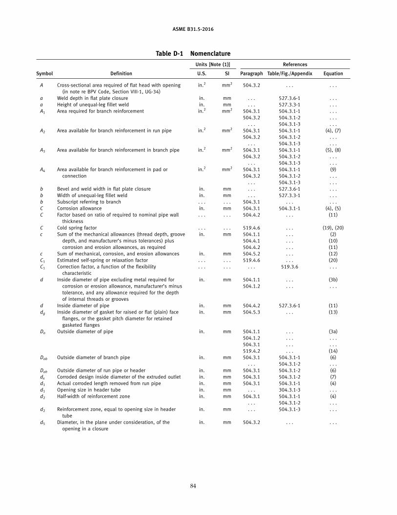
ASME B31.5-2016
Table D-1 Nomenclature
Units [Note (1)] References
Symbol Definition U.S. SI Paragraph Table/Fig./Appendix Equation
A Cross-sectional area required of flat head with opening in.2 mm2 504.3.2 . . . . . .(in note re BPV Code, Section VIII-1, UG-34)
a Weld depth in flat plate closure in. mm . . . 527.3.6-1 . . .a Height of unequal-leg fillet weld in. mm . . . 527.3.3-1 . . .A1 Area required for branch reinforcement in.2 mm2 504.3.1 504.3.1-1 . . .
504.3.2 504.3.1-2 . . .. . . 504.3.1-3 . . .
A2 Area available for branch reinforcement in run pipe in.2 mm2 504.3.1 504.3.1-1 (4), (7)504.3.2 504.3.1-2 . . .
. . . 504.3.1-3 . . .A3 Area available for branch reinforcement in branch pipe in.2 mm2 504.3.1 504.3.1-1 (5), (8)
504.3.2 504.3.1-2 . . .. . . 504.3.1-3 . . .
A4 Area available for branch reinforcement in pad or in.2 mm2 504.3.1 504.3.1-1 (9)connection 504.3.2 504.3.1-2 . . .
. . . 504.3.1-3 . . .b Bevel and weld width in flat plate closure in. mm . . . 527.3.6-1 . . .b Width of unequal-leg fillet weld in. mm . . . 527.3.3-1 . . .b Subscript referring to branch . . . . . . 504.3.1 . . . . . .C Corrosion allowance in. mm 504.3.1 504.3.1-1 (4), (5)C Factor based on ratio of required to nominal pipe wall . . . . . . 504.4.2 . . . (11)
thicknessC Cold spring factor . . . . . . 519.4.6 . . . (19), (20)c Sum of the mechanical allowances (thread depth, groove in. mm 504.1.1 . . . (2)
depth, and manufacturer’s minus tolerances) plus 504.4.1 . . . (10)corrosion and erosion allowances, as required 504.4.2 . . . (11)
c Sum of mechanical, corrosion, and erosion allowances in. mm 504.5.2 . . . (12)C1 Estimated self-spring or relaxation factor . . . . . . 519.4.6 . . . (20)C1 Correction factor, a function of the flexibility . . . . . . . . . 519.3.6 . . .
characteristicd Inside diameter of pipe excluding metal required for in. mm 504.1.1 . . . (3b)
corrosion or erosion allowance, manufacturer’s minus 504.1.2 . . . . . .tolerance, and any allowance required for the depthof internal threads or grooves
d Inside diameter of pipe in. mm 504.4.2 527.3.6-1 (11)dg Inside diameter of gasket for raised or flat (plain) face in. mm 504.5.3 . . . (13)
flanges, or the gasket pitch diameter for retainedgasketed flanges
Do Outside diameter of pipe in. mm 504.1.1 . . . (3a)504.1.2 . . . . . .504.3.1 . . . . . .519.4.2 . . . (14)
Dob Outside diameter of branch pipe in. mm 504.3.1 504.3.1-1 (6). . . 504.3.1-2 . . .
Doh Outside diameter of run pipe or header in. mm 504.3.1 504.3.1-2 (6)dx Corroded design inside diameter of the extruded outlet in. mm 504.3.1 504.3.1-2 (7)d1 Actual corroded length removed from run pipe in. mm 504.3.1 504.3.1-1 (4)d1 Opening size in header tube in. mm . . . 304.3.1-3 . . .d2 Half-width of reinforcement zone in. mm 504.3.1 504.3.1-1 (4)
. . . 504.3.1-2 . . .d2 Reinforcement zone, equal to opening size in header in. mm . . . 504.3.1-3 . . .
tubed5 Diameter, in the plane under consideration, of the in. mm 504.3.2 . . . . . .
opening in a closure
84
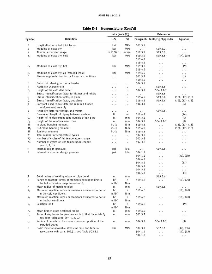
ASME B31.5-2016
Table D-1 Nomenclature (Cont’d)
Units [Note (1)] References
Symbol Definition U.S. SI Paragraph Table/Fig./Appendix Equation
E Longitudinal or spiral joint factor ksi MPa 502.3.1 . . . . . .E Modulus of elasticity ksi MPa . . . 519.3.2 . . .e Thermal expansion range in./100 ft mm/m 519.3.1 519.3.1 . . .Ec Modulus of elasticity, cold ksi MPa 519.3.2 519.3.6 (14), (19)
519.4.2 . . . . . .519.4.6 . . . . . .
Eh Modulus of elasticity, hot ksi MPa 519.3.2 . . . (19)519.4.6 . . . . . .
EJ Modulus of elasticity, as installed (cold) ksi MPa 519.4.5 . . . . . .f Stress-range reduction factor for cyclic conditions . . . . . . 502.3.2 . . . (1)
519.4.2 . . . . . .h Subscript referring to run or header . . . . . . 504.3.1 . . . . . .h Flexibility characteristic . . . . . . . . . 519.3.6 . . .hx Height of the extruded outlet . . . . . . 504.3.1 504.3.1-2i Stress intensification factor for fittings and miters . . . . . . . . . 519.3.6 . . .ii Stress intensification factor, in-plane . . . . . . 519.4.5 519.3.6 (16), (17), (18)io Stress intensification factor, out-plane . . . . . . 519.4.5 519.3.6 (16), (17), (18)K Constant used to calculate the required branch . . . . . . 504.3.1 . . . (6)
reinforcement area, A1
k Flexibility factor for fittings and miters . . . . . . . . . 519.3.6 . . .L Developed length of piping between anchors ft m 519.4.2 . . . (14)L4 Height of reinforcement zone outside of run pipe in. mm 504.3.1 . . . (5)L5 Height of the reinforcement zone in. mm 504.3.1 504.3.1-2 (8)Mi In-plane bending moment in.-lb N-m 519.4.5 . . . (16), (17), (18)Mo Out-plane bending moment in.-lb N-m 519.4.5 . . . (16), (17), (18)Mt Torsional moment in.-lb N-m 519.4.5 . . . . . .N Total number of temperature cycles . . . . . . 502.3.2 . . . . . .NE Number of cycles of full temperature change . . . . . . 502.3.2 . . . . . .Nn Number of cycles of less temperature change . . . . . . 502.3.2 . . . . . .
(np 1, 2, ...)P Internal design pressure psi kPa . . . 519.3.6 . . .P Internal or external design pressure psi kPa 504.1.1 . . . . . .
504.1.2 . . . (3a), (3b)504.4.1 . . . . . .504.4.2 . . . (11)504.5.1 . . . . . .504.5.2 . . . . . .504.5.3 . . . (13)
R Bend radius of welding elbow or pipe bend in. mm . . . 519.3.6 . . .R Range of reaction forces or moments corresponding to lbf N 519.4.6 . . . (19), (20)
the full expansion range based on Ec in.-lbf N-mr Mean radius of matching pipe in. mm . . . 519.3.6 . . .Rc Maximum reaction forces or moments estimated to occur lbf N 519.4.6 . . . (19), (20)
in the cold conditions in.-lbf N-mRh Maximum reaction forces or moments estimated to occur lbf N 519.4.6 . . . (19), (20)
in the hot conditions in.-lbf N-mRL Reaction limit lbf N 519.4.6 . . . (19)
in.-lbf N-mrm Mean branch cross-sectional radius in. mm 519.4.5 . . . . . .rn Ratio of any lesser temperature cycle to that for which SE in. mm 502.3.2 . . . . . .
has been calculated (np 1, 2, ...)rx Radius of curvature of external contoured portion of the in. mm 504.3.1 504.3.1-2 (9)
extruded outletS Basic material allowable stress for pipe and tube in ksi MPa 502.3.1 502.3.1 (3a), (3b)
accordance with para. 502.3.1 and Table 502.3.1 504.1.1 . . . (11), (13)504.1.2 . . . . . .
85
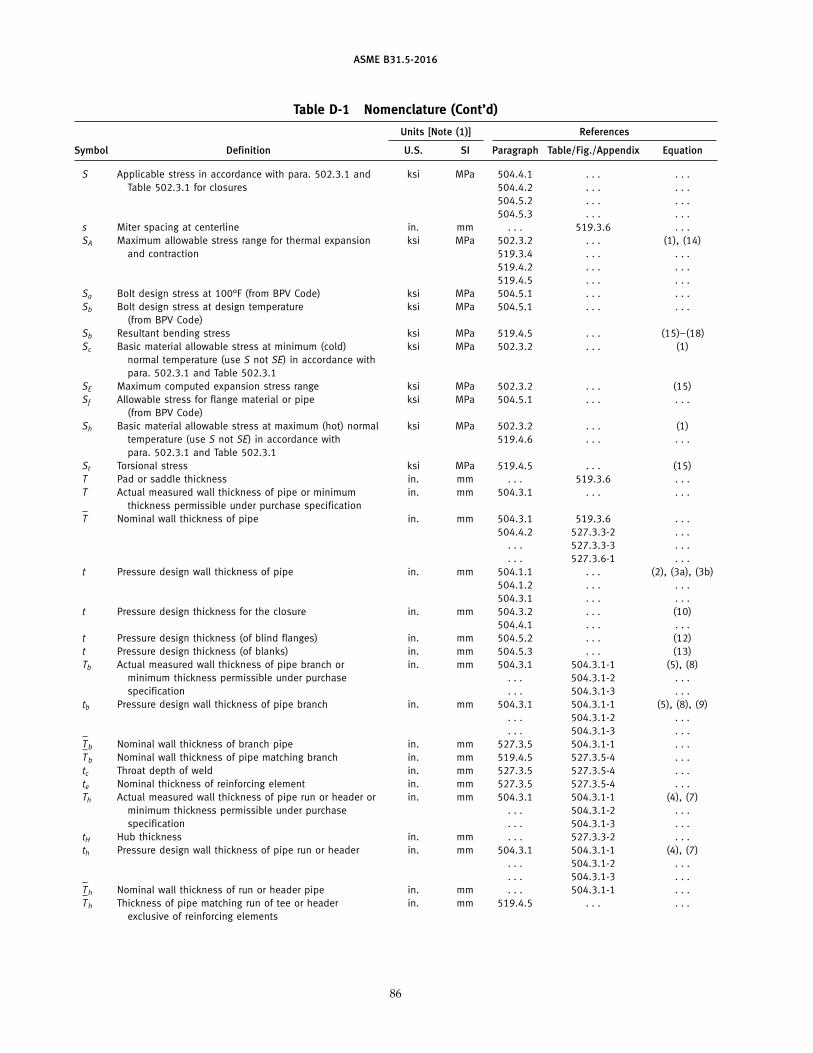
ASME B31.5-2016
Table D-1 Nomenclature (Cont’d)
Units [Note (1)] References
Symbol Definition U.S. SI Paragraph Table/Fig./Appendix Equation
S Applicable stress in accordance with para. 502.3.1 and ksi MPa 504.4.1 . . . . . .Table 502.3.1 for closures 504.4.2 . . . . . .
504.5.2 . . . . . .504.5.3 . . . . . .
s Miter spacing at centerline in. mm . . . 519.3.6 . . .SA Maximum allowable stress range for thermal expansion ksi MPa 502.3.2 . . . (1), (14)
and contraction 519.3.4 . . . . . .519.4.2 . . . . . .519.4.5 . . . . . .
Sa Bolt design stress at 100°F (from BPV Code) ksi MPa 504.5.1 . . . . . .Sb Bolt design stress at design temperature ksi MPa 504.5.1 . . . . . .
(from BPV Code)Sb Resultant bending stress ksi MPa 519.4.5 . . . (15)–(18)Sc Basic material allowable stress at minimum (cold) ksi MPa 502.3.2 . . . (1)
normal temperature (use S not SE) in accordance withpara. 502.3.1 and Table 502.3.1
SE Maximum computed expansion stress range ksi MPa 502.3.2 . . . (15)Sf Allowable stress for flange material or pipe ksi MPa 504.5.1 . . . . . .
(from BPV Code)Sh Basic material allowable stress at maximum (hot) normal ksi MPa 502.3.2 . . . (1)
temperature (use S not SE) in accordance with 519.4.6 . . . . . .para. 502.3.1 and Table 502.3.1
St Torsional stress ksi MPa 519.4.5 . . . (15)T Pad or saddle thickness in. mm . . . 519.3.6 . . .T Actual measured wall thickness of pipe or minimum in. mm 504.3.1 . . . . . .
thickness permissible under purchase specificationT–
Nominal wall thickness of pipe in. mm 504.3.1 519.3.6 . . .504.4.2 527.3.3-2 . . .
. . . 527.3.3-3 . . .
. . . 527.3.6-1 . . .t Pressure design wall thickness of pipe in. mm 504.1.1 . . . (2), (3a), (3b)
504.1.2 . . . . . .504.3.1 . . . . . .
t Pressure design thickness for the closure in. mm 504.3.2 . . . (10)504.4.1 . . . . . .
t Pressure design thickness (of blind flanges) in. mm 504.5.2 . . . (12)t Pressure design thickness (of blanks) in. mm 504.5.3 . . . (13)Tb Actual measured wall thickness of pipe branch or in. mm 504.3.1 504.3.1-1 (5), (8)
minimum thickness permissible under purchase . . . 504.3.1-2 . . .specification . . . 504.3.1-3 . . .
tb Pressure design wall thickness of pipe branch in. mm 504.3.1 504.3.1-1 (5), (8), (9). . . 504.3.1-2 . . .. . . 504.3.1-3 . . .
T–
b Nominal wall thickness of branch pipe in. mm 527.3.5 504.3.1-1 . . .T–
b Nominal wall thickness of pipe matching branch in. mm 519.4.5 527.3.5-4 . . .tc Throat depth of weld in. mm 527.3.5 527.3.5-4 . . .te Nominal thickness of reinforcing element in. mm 527.3.5 527.3.5-4 . . .Th Actual measured wall thickness of pipe run or header or in. mm 504.3.1 504.3.1-1 (4), (7)
minimum thickness permissible under purchase . . . 504.3.1-2 . . .specification . . . 504.3.1-3 . . .
tH Hub thickness in. mm . . . 527.3.3-2 . . .th Pressure design wall thickness of pipe run or header in. mm 504.3.1 504.3.1-1 (4), (7)
. . . 504.3.1-2 . . .
. . . 504.3.1-3 . . .T–
h Nominal wall thickness of run or header pipe in. mm . . . 504.3.1-1 . . .T–
h Thickness of pipe matching run of tee or header in. mm 519.4.5 . . . . . .exclusive of reinforcing elements
86
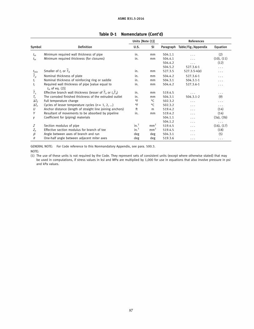
ASME B31.5-2016
Table D-1 Nomenclature (Cont’d)
Units [Note (1)] References
Symbol Definition U.S. SI Paragraph Table/Fig./Appendix Equation
tm Minimum required wall thickness of pipe in. mm 504.1.1 . . . (2)tm Minimum required thickness (for closures) in. mm 504.4.1 . . . (10), (11)
504.4.2 . . . (12)504.5.2 527.3.6-1 . . .
tmin Smaller of tc or T–
b in. mm 527.3.5 527.3.5-4(e) . . .
T–
p Nominal thickness of plate in. mm 504.4.2 527.3.6-1 . . .tr Nominal thickness of reinforcing ring or saddle in. mm 504.3.1 504.3.1-1 . . .tr Required wall thickness of pipe [value equal to in. mm 504.4.2 527.3.6-1 . . .
tm of eq. (2)]T–
s Effective branch wall thickness (lesser of T–
h or ioT–
b) in. mm 519.4.5 . . . . . .Tx The corroded finished thickness of the extruded outlet in. mm 504.3.1 504.3.1-2 (9)�TE Full temperature change °F °C 502.3.2 . . . . . .�Tn Cycles of lesser temperature cycles (np 1, 2, ...) °F °C 502.3.2 . . . . . .U Anchor distance (length of straight line joining anchors) ft m 519.4.2 . . . (14)Y Resultant of movements to be absorbed by pipeline in. mm 519.4.2 . . . (14)y Coefficient for (piping) materials 504.1.1 . . . (3a), (3b)
504.1.2 . . . . . .Z Section modulus of pipe in.3 mm3 519.4.5 . . . (16), (17)Ze Effective section modulus for branch of tee in.3 mm3 519.4.5 . . . (18)� Angle between axes of branch and run deg deg 504.3.1 . . . (5)� One-half angle between adjacent miter axes deg deg 519.3.6 . . . . . .
GENERAL NOTE: For Code reference to this Nonmandatory Appendix, see para. 500.3.
NOTE:(1) The use of these units is not required by the Code. They represent sets of consistent units (except where otherwise stated) that may
be used in computations, if stress values in ksi and MPa are multiplied by 1,000 for use in equations that also involve pressure in psiand kPa values.
87

INTENTIONALLY LEFT BLANK
88
ASME CODE FOR PRESSURE PIPING, B31
Power Piping . . . . . . . . . . . . . . . . . . . . . . . . . . . . . . . . . . . . . . . . . . . . . . . . . . . . . . . . . . . . . . . . . . . . . . . . . . . . . . . . . . . . . . . . . . . . . . . B31.1-2014Process Piping . . . . . . . . . . . . . . . . . . . . . . . . . . . . . . . . . . . . . . . . . . . . . . . . . . . . . . . . . . . . . . . . . . . . . . . . . . . . . . . . . . . . . . . . . . . . . . B31.3-2014Tuberias de Proceso . . . . . . . . . . . . . . . . . . . . . . . . . . . . . . . . . . . . . . . . . . . . . . . . . . . . . . . . . . . . . . . . . . . . . . . . . . . . . . . . . . . . . . . . . B31.3-2010Pipeline Transportation Systems for Liquids and Slurries. . . . . . . . . . . . . . . . . . . . . . . . . . . . . . . . . . . . . . . . . . . . . . . . . . . . . . . . . . . . B31.4-2016Refrigeration Piping and Heat Transfer Components . . . . . . . . . . . . . . . . . . . . . . . . . . . . . . . . . . . . . . . . . . . . . . . . . . . . . . . . . . . . . . . . B31.5-2016Gas Transmission and Distribution Piping Systems . . . . . . . . . . . . . . . . . . . . . . . . . . . . . . . . . . . . . . . . . . . . . . . . . . . . . . . . . . . . . . . . B31.8-2014Managing System Integrity of Gas Pipelines . . . . . . . . . . . . . . . . . . . . . . . . . . . . . . . . . . . . . . . . . . . . . . . . . . . . . . . . . . . . . . . . . . . . . B31.8S-2014Gestion de Integridad de Sistemas de Gasoductos . . . . . . . . . . . . . . . . . . . . . . . . . . . . . . . . . . . . . . . . . . . . . . . . . . . . . . . . . . . . . . . B31.8S-2010Building Services Piping . . . . . . . . . . . . . . . . . . . . . . . . . . . . . . . . . . . . . . . . . . . . . . . . . . . . . . . . . . . . . . . . . . . . . . . . . . . . . . . . . . . . . . B31.9-2014Hydrogen Piping and Pipelines. . . . . . . . . . . . . . . . . . . . . . . . . . . . . . . . . . . . . . . . . . . . . . . . . . . . . . . . . . . . . . . . . . . . . . . . . . . . . . . . B31.12-2014Standard for the Seismic Design and Retrofit of Above-Ground Piping Systems . . . . . . . . . . . . . . . . . . . . . . . . . . . . . . . . . . . . . . . . . B31E-2008Manual for Determining the Remaining Strength of Corroded Pipelines: Supplement to ASME B31 Code for Pressure Piping. . . . . B31G-2012Manual para la determinacion de la resistencia remanente de tuberias corroidas . . . . . . . . . . . . . . . . . . . . . . . . . . . . . . . . . . . . . . . B31G-2012Standard Test Method for Determining Stress Intensification Factors (i-Factors) for Metallic Piping Components . . . . . . . . . B31J-2008 (R2013)Metodo de prueba estandar para determinar factores de intensificacion de esfuerzo (Factores i) para componentes
de tuberias metalicas . . . . . . . . . . . . . . . . . . . . . . . . . . . . . . . . . . . . . . . . . . . . . . . . . . . . . . . . . . . . . . . . . . . . . . . . . . . . . . . . B31J-2008 (R2013)Pipeline Personnel Qualification. . . . . . . . . . . . . . . . . . . . . . . . . . . . . . . . . . . . . . . . . . . . . . . . . . . . . . . . . . . . . . . . . . . . . . . . . . . . . . . . B31Q-2014Calificacion del personal de lineas de tuberias. . . . . . . . . . . . . . . . . . . . . . . . . . . . . . . . . . . . . . . . . . . . . . . . . . . . . . . . . . . . . . . . . . . . B31Q-2010Standard Toughness Requirements for Piping . . . . . . . . . . . . . . . . . . . . . . . . . . . . . . . . . . . . . . . . . . . . . . . . . . . . . . . . . . . . . . . . . . . . . .B31T-2010
The ASME Publications Catalog shows a complete list of all the Standards published by the Society. For a complimentary catalog, or the latestinformation about our publications, call 1-800-THE-ASME (1-800-843-2763).

ASME Services
ASME is committed to developing and delivering technical information. At ASME’s Customer Care, we make every effort to answer your questionsand expedite your orders. Our representatives are ready to assist you in the following areas:
ASME Press Member Services & Benefits Public InformationCodes & Standards Other ASME Programs Self-Study CoursesCredit Card Orders Payment Inquiries Shipping InformationIMechE Publications Professional Development Subscriptions/Journals/MagazinesMeetings & Conferences Short Courses Symposia VolumesMember Dues Status Publications Technical Papers
How can you reach us? It’s easier than ever!
There are four options for making inquiries* or placing orders. Simply mail, phone, fax, or E-mail us and a Customer Care representative willhandle your request.
Mail Call Toll Free Fax—24 hours E-Mail—24 hoursASME US & Canada: 800-THE-ASME 973-882-1717 [email protected] Clove Road, 6th Floor (800-843-2763) 973-882-5155Little Falls, New Jersey Mexico: 95-800-THE-ASME07424-2138 (95-800-843-2763)
* Customer Care staff are not permitted to answer inquiries about the technical content of this code or standard. Information as to whetheror not technical inquiries are issued to this code or standard is shown on the copyright page. All technical inquiries must be submitted inwriting to the staff secretary. Additional procedures for inquiries may be listed within.
ASME B31.5-2016