networking fundamentals
TRANSCRIPT
NETWORKINGFUNDAMENTALS
SCOTT M. ROGALA
The world of networking and the world of picture archiving and commu-nications systems (PACS) are two different environments that converge
in such a way as to require a very special skill set. This chapter gives you thebasics of computer networking and shows you how they apply to a PACSenvironment.
It is important to appreciate the role the network plays in a PACSimplementation. Our goal is not to make you an expert network engineer,but rather to give you enough information so you can navigate the often con-fusing, cluttered world of computer networking. With the right kind ofinformation you will feel comfortable enough with the terminology tounderstand what your vendor(s) are providing, on both the PACS andnetwork sides. We also want to impress on you the importance of goodnetwork design and implementation; these are integral parts of the PACSsystem. Failure to create a strong, robust network infrastructure will resultin unhappy users, finger-pointing, and loss of confidence in PACS. If thenetwork is designed and implemented correctly, it can contribute immenselyto a successful PACS implementation.
14CHAPTER
DRE14 11/16/2005 9:47 AM Page 269
We will start with some basic concepts, intended not for the veterannetwork engineer but for those who have had no exposure to computer networking. Through extensive use of analogies, most of you will grasp theconcepts well enough to see how much thought is needed in the design ofnetworks, and why the necessary investment of time and capital must bemade to achieve a successful implementation. We hope that by explaining infamiliar terms what is considered wizardry and hocus-pocus will help bridgethe gap between network engineers and radiologists.
FOR REFERENCE: THE INTERNATIONALORGANIZATION FOR STANDARDIZATION MODEL
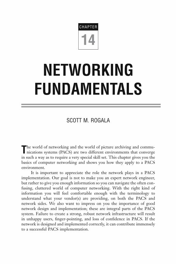
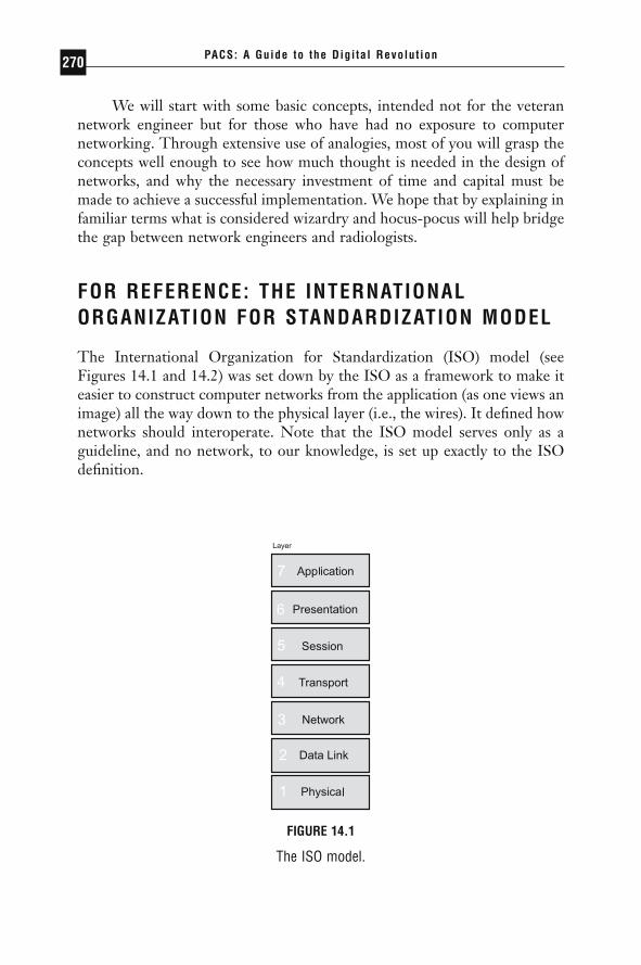
The International Organization for Standardization (ISO) model (seeFigures 14.1 and 14.2) was set down by the ISO as a framework to make iteasier to construct computer networks from the application (as one views animage) all the way down to the physical layer (i.e., the wires). It defined hownetworks should interoperate. Note that the ISO model serves only as aguideline, and no network, to our knowledge, is set up exactly to the ISOdefinition.
PACS: A Guide to the Digi tal Revolut ion270
FIGURE 14.1
The ISO model.
DRE14 11/16/2005 9:47 AM Page 270
A SIMPLE NETWORK
Let us start by setting up a very simple network of 2 computers, a server anda client, to illustrate many of the concepts.
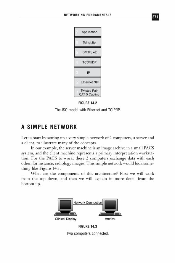
In our example, the server machine is an image archive in a small PACSsystem, and the client machine represents a primary interpretation worksta-tion. For the PACS to work, these 2 computers exchange data with eachother, for instance, radiology images. This simple network would look some-thing like Figure 14.3.
What are the components of this architecture? First we will work from the top down, and then we will explain in more detail from the bottom up.
NETWORKING FUNDAMENTALS 271
Twisted Pair CAT 5 Cabling
etc.
FIGURE 14.2
The ISO model with Ethernet and TCIP/IP.
FIGURE 14.3
Two computers connected.
DRE14 11/16/2005 9:47 AM Page 271

THE ARCHITECTURE AND COMPONENTS AND THE INTERNATIONAL ORGANIZATION FOR STANDARDIZATION MODEL
The archive machine hosts the images the clinical display needs. An appli-cation on the archive knows how to answer image requests from clinical dis-plays. In the ISO model this portion of communication happens at the higherlevels. The application needs to transfer this information from itself to theclinical display requesting the information. The overall picture would looksomething like Figure 14.4. Figure 14.4 is an extremely simplified way oflooking at the ISO model. It is displayed in this way to emphasize the fun-damental components that we will need to understand to effectively makePACS networking decisions.
Each layer is interested only in the exchange of information betweenthe layer directly above and that directly below. (For example, the hardwarelayer generally does not care how the protocol layers pass information to theapplication: it is concerned only with passing the information up to the pro-tocol layer.) In this way the application communicates with the protocolstack, which in turn hands the information over to the hardware layer (thenetwork interface card, or NIC). Next, the hardware layer puts the infor-mation out onto the network.
Each layer has a different and well-defined task. The application layerknows the data it wants to transmit, and it knows which machine it wants totransmit it to. The protocol stack knows how to find the computer in ques-tion (or how to find a device that knows how to locate it). The network layerknows how to transmit the data over the network, and the network knows
PACS: A Guide to the Digi tal Revolut ion272
Data Link(Hardware)
Network(Protocol)
FIGURE 14.4
A simplified ISO model.
DRE14 11/16/2005 9:47 AM Page 272
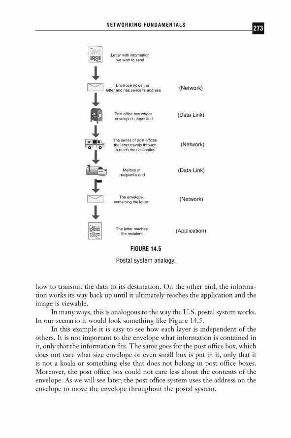
how to transmit the data to its destination. On the other end, the informa-tion works its way back up until it ultimately reaches the application and theimage is viewable.
In many ways, this is analogous to the way the U.S. postal system works.In our scenario it would look something like Figure 14.5.
In this example it is easy to see how each layer is independent of theothers. It is not important to the envelope what information is contained init, only that the information fits. The same goes for the post office box, whichdoes not care what size envelope or even small box is put in it, only that itis not a koala or something else that does not belong in post office boxes.Moreover, the post office box could not care less about the contents of theenvelope. As we will see later, the post office system uses the address on theenvelope to move the envelope throughout the postal system.
NETWORKING FUNDAMENTALS 273
FIGURE 14.5
Postal system analogy.
DRE14 11/16/2005 9:47 AM Page 273
Now we will work our way back up through the layers, starting withthe physical layer. The physical layer consists of the wires that make up thenetwork. It may also include the NIC in the computers attached to it. Ingeneral, the physical layer can be thought of as the “plumbing” or highwayof a network. The quality and width of the pipe can determine the speed atwhich the data can be transmitted, the reliability of the network, and the distance at which the data can be transmitted.
Most of you have probably seen the cable coming out of the wall plateand connecting to your computer’s NIC. These cables are commonly knownas unshielded twisted pair (UTP) copper cabling, also referred to as Cate-gory 5 (CAT5) or Category 3 (CAT3), depending on the exact quality. Net-works can also be made up of telephone wires, coax cable (otherwise knownas thinnet or 10Base5), and other types of wires. One advance that haschanged networks dramatically in recent years has been the use of fiber-opticcabling, which can transmit more data over longer distances than con-ventional cabling by using light or lasers instead of electrical signals. Therelatively high cost of fiber cabling has relegated it generally to the core ofnetworks where bandwidth is needed most. Of late, fiber cabling has becomethe only type of cabling that can support faster transmission rates, and it is finding its way to the desktop as it becomes more popular and less ex-pensive. Later in this chapter, we will discuss which types of cabling are generally used where.
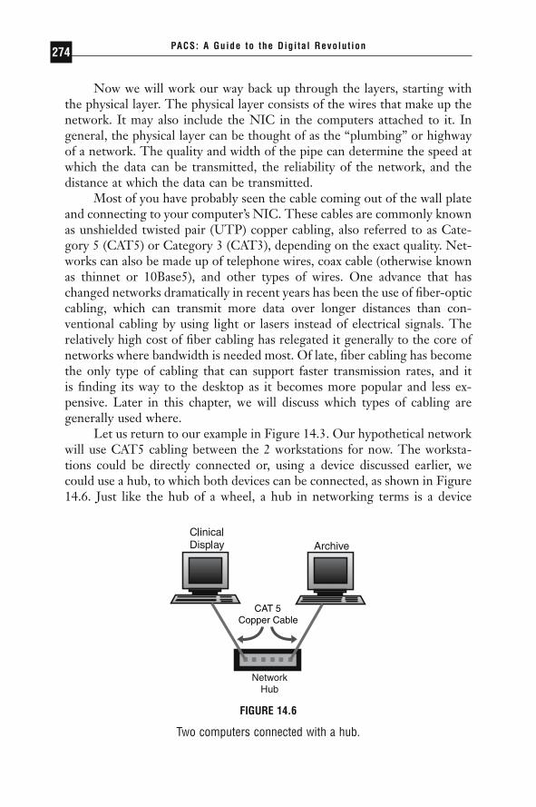
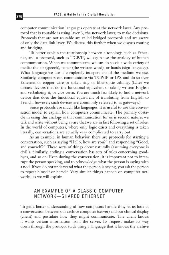
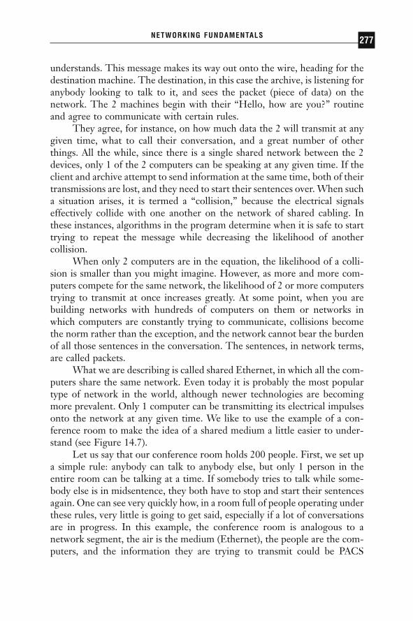
Let us return to our example in Figure 14.3. Our hypothetical networkwill use CAT5 cabling between the 2 workstations for now. The worksta-tions could be directly connected or, using a device discussed earlier, wecould use a hub, to which both devices can be connected, as shown in Figure14.6. Just like the hub of a wheel, a hub in networking terms is a device
PACS: A Guide to the Digi tal Revolut ion274
CAT 5Copper Cable
FIGURE 14.6
Two computers connected with a hub.
DRE14 11/16/2005 9:47 AM Page 274
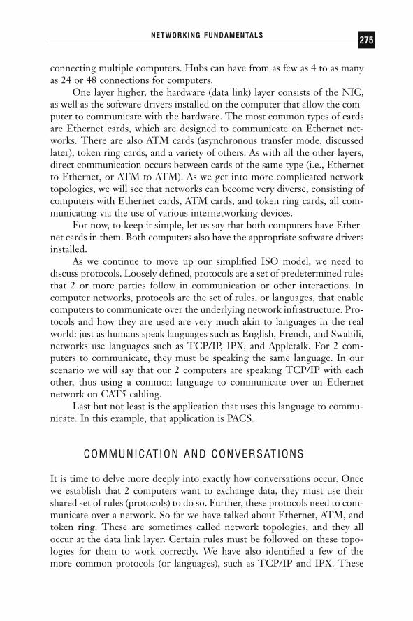
connecting multiple computers. Hubs can have from as few as 4 to as manyas 24 or 48 connections for computers.
One layer higher, the hardware (data link) layer consists of the NIC,as well as the software drivers installed on the computer that allow the com-puter to communicate with the hardware. The most common types of cardsare Ethernet cards, which are designed to communicate on Ethernet net-works. There are also ATM cards (asynchronous transfer mode, discussedlater), token ring cards, and a variety of others. As with all the other layers,direct communication occurs between cards of the same type (i.e., Ethernetto Ethernet, or ATM to ATM). As we get into more complicated networktopologies, we will see that networks can become very diverse, consisting ofcomputers with Ethernet cards, ATM cards, and token ring cards, all com-municating via the use of various internetworking devices.
For now, to keep it simple, let us say that both computers have Ether-net cards in them. Both computers also have the appropriate software driversinstalled.
As we continue to move up our simplified ISO model, we need todiscuss protocols. Loosely defined, protocols are a set of predetermined rulesthat 2 or more parties follow in communication or other interactions. Incomputer networks, protocols are the set of rules, or languages, that enablecomputers to communicate over the underlying network infrastructure. Pro-tocols and how they are used are very much akin to languages in the realworld: just as humans speak languages such as English, French, and Swahili,networks use languages such as TCP/IP, IPX, and Appletalk. For 2 com-puters to communicate, they must be speaking the same language. In ourscenario we will say that our 2 computers are speaking TCP/IP with eachother, thus using a common language to communicate over an Ethernetnetwork on CAT5 cabling.
Last but not least is the application that uses this language to commu-nicate. In this example, that application is PACS.
COMMUNICATION AND CONVERSATIONS
It is time to delve more deeply into exactly how conversations occur. Oncewe establish that 2 computers want to exchange data, they must use theirshared set of rules (protocols) to do so. Further, these protocols need to com-municate over a network. So far we have talked about Ethernet, ATM, andtoken ring. These are sometimes called network topologies, and they alloccur at the data link layer. Certain rules must be followed on these topo-logies for them to work correctly. We have also identified a few of the more common protocols (or languages), such as TCP/IP and IPX. These
NETWORKING FUNDAMENTALS 275
DRE14 11/16/2005 9:47 AM Page 275
computer communication languages operate at the network layer. Any pro-tocol that is routable is using layer 3, the network layer, to make decisions.Protocols that are not routable are called bridged protocols and are awareof only the data link layer. We discuss this further when we discuss routingand bridging.
To better explain the relationship between a topology, such as Ether-net, and a protocol, such as TCP/IP, we again use the analogy of humancommunication. When we communicate, we can do so via a wide variety ofmedia: the air (speech), paper (the written word), or hands (sign language).What language we use is completely independent of the medium we use.Similarly, computers can communicate via TCP/IP or IPX and do so overEthernet or copper wire or token ring or fiber-optic cabling. (Later wediscuss devices that do the functional equivalent of taking written Englishand verbalizing it, or vice versa. You are much less likely to find a networkdevice that does the functional equivalent of translating from English toFrench, however; such devices are commonly referred to as gateways.)
Since protocols are much like languages, it is useful to use the conver-sation model to explain how computers communicate. The primary obsta-cle in using this analogy is that communication for us is second nature; wetalk and write without being aware that we are in fact following a set of rules.In the world of computers, where only logic exists and everything is takenliterally, conversations are actually very complicated to carry out.
As an example, in human behavior, there are protocols for starting aconversation, such as saying “Hello, how are you?” and responding “Good,and yourself ?” These sorts of things occur naturally (assuming everyone iscivil!). Similarly, ending a conversation has sets of rules concerning good-byes, and so on. Even during the conversation, it is important not to inter-rupt the person speaking, and to acknowledge what the person is saying witha nod. If you do not understand what the person is saying, you ask the personto repeat himself or herself. Very similar things happen on computer net-works, as we will explain.
AN EXAMPLE OF A CLASSIC COMPUTERNETWORK—SHARED ETHERNET
To get a better understanding of how computers handle this, let us look ata conversation between our archive computer (server) and our clinical display(client) and postulate how they might communicate. The client knows it wants certain information from the server. Its request makes its way down through the protocol stack using a language that it knows the archive
PACS: A Guide to the Digi tal Revolut ion276
DRE14 11/16/2005 9:47 AM Page 276
understands. This message makes its way out onto the wire, heading for thedestination machine. The destination, in this case the archive, is listening foranybody looking to talk to it, and sees the packet (piece of data) on thenetwork. The 2 machines begin with their “Hello, how are you?” routineand agree to communicate with certain rules.
They agree, for instance, on how much data the 2 will transmit at anygiven time, what to call their conversation, and a great number of otherthings. All the while, since there is a single shared network between the 2devices, only 1 of the 2 computers can be speaking at any given time. If theclient and archive attempt to send information at the same time, both of theirtransmissions are lost, and they need to start their sentences over. When sucha situation arises, it is termed a “collision,” because the electrical signalseffectively collide with one another on the network of shared cabling. Inthese instances, algorithms in the program determine when it is safe to starttrying to repeat the message while decreasing the likelihood of another collision.
When only 2 computers are in the equation, the likelihood of a colli-sion is smaller than you might imagine. However, as more and more com-puters compete for the same network, the likelihood of 2 or more computerstrying to transmit at once increases greatly. At some point, when you arebuilding networks with hundreds of computers on them or networks inwhich computers are constantly trying to communicate, collisions becomethe norm rather than the exception, and the network cannot bear the burdenof all those sentences in the conversation. The sentences, in network terms,are called packets.
What we are describing is called shared Ethernet, in which all the com-puters share the same network. Even today it is probably the most populartype of network in the world, although newer technologies are becomingmore prevalent. Only 1 computer can be transmitting its electrical impulsesonto the network at any given time. We like to use the example of a con-ference room to make the idea of a shared medium a little easier to under-stand (see Figure 14.7).
Let us say that our conference room holds 200 people. First, we set upa simple rule: anybody can talk to anybody else, but only 1 person in theentire room can be talking at a time. If somebody tries to talk while some-body else is in midsentence, they both have to stop and start their sentencesagain. One can see very quickly how, in a room full of people operating underthese rules, very little is going to get said, especially if a lot of conversationsare in progress. In this example, the conference room is analogous to anetwork segment, the air is the medium (Ethernet), the people are the com-puters, and the information they are trying to transmit could be PACS
NETWORKING FUNDAMENTALS 277
DRE14 11/16/2005 9:47 AM Page 277

knowledge, baseball news, or the latest juicy gossip. Some could be speak-ing English or French, but only those who understand French are able to communicate with others who understand French. Similarly, on ournetwork, computers could be talking TCP/IP to one another while othersare speaking IPX. They all share the same network segment, but they com-municate only with those speaking the same language.
ENTER BRIDGING
You can see in this scenario how inefficient such communications can be.The same was true for early networks. The first attempt to tackle theproblem of collision was with a concept called bridging. A bridge is a devicethat connects 2 or more networks together. (As we see later, a bridge under-stands only the 2 lower layers of our simplified ISO model. Next we talkabout a device that understands the lower 3 layers, a router.)
To explain exactly what a bridge does, let us take the conference roomand split it in two. We assign each person a unique number, known as his orher MAC address, or media access control address. The MAC address isunique not only in the conference room, but also throughout the world. Incomputing, the MAC address is derived from the network interface card. Itis how each computer (or in our example, each person) is identified.
In Figure 14.8 you see that the conference room is split in two, withpeople numbered 1, 2, and 3 on the left side and 4, 5, and 6 on the rightside. In the middle of the conference room is a dividing wall, which stops allnoise unless the bridge, B, allows it through. It is the bridge’s job to keep
PACS: A Guide to the Digi tal Revolut ion278
4 PACS, Baseball3 English or TCP/IP2 The People1 The Air the Sound Travels Over
FIGURE 14.7
The conference room.
DRE14 11/16/2005 9:47 AM Page 278
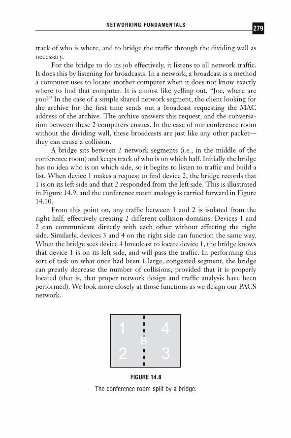
track of who is where, and to bridge the traffic through the dividing wall asnecessary.
For the bridge to do its job effectively, it listens to all network traffic.It does this by listening for broadcasts. In a network, a broadcast is a methoda computer uses to locate another computer when it does not know exactlywhere to find that computer. It is almost like yelling out, “Joe, where areyou?” In the case of a simple shared network segment, the client looking forthe archive for the first time sends out a broadcast requesting the MACaddress of the archive. The archive answers this request, and the conversa-tion between these 2 computers ensues. In the case of our conference roomwithout the dividing wall, these broadcasts are just like any other packet—they can cause a collision.
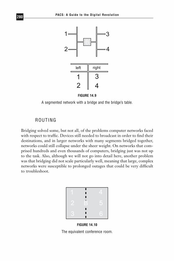
A bridge sits between 2 network segments (i.e., in the middle of theconference room) and keeps track of who is on which half. Initially the bridgehas no idea who is on which side, so it begins to listen to traffic and build alist. When device 1 makes a request to find device 2, the bridge records that1 is on its left side and that 2 responded from the left side. This is illustratedin Figure 14.9, and the conference room analogy is carried forward in Figure14.10.
From this point on, any traffic between 1 and 2 is isolated from theright half, effectively creating 2 different collision domains. Devices 1 and 2 can communicate directly with each other without affecting the right side. Similarly, devices 3 and 4 on the right side can function the same way.When the bridge sees device 4 broadcast to locate device 1, the bridge knowsthat device 1 is on its left side, and will pass the traffic. In performing thissort of task on what once had been 1 large, congested segment, the bridgecan greatly decrease the number of collisions, provided that it is properlylocated (that is, that proper network design and traffic analysis have beenperformed). We look more closely at those functions as we design our PACSnetwork.
NETWORKING FUNDAMENTALS 279
FIGURE 14.8
The conference room split by a bridge.
DRE14 11/16/2005 9:47 AM Page 279
ROUTING
Bridging solved some, but not all, of the problems computer networks facedwith respect to traffic. Devices still needed to broadcast in order to find theirdestinations, and in larger networks with many segments bridged together,networks could still collapse under the sheer weight. On networks that com-prised hundreds and even thousands of computers, bridging just was not upto the task. Also, although we will not go into detail here, another problemwas that bridging did not scale particularly well, meaning that large, complexnetworks were susceptible to prolonged outages that could be very difficultto troubleshoot.
PACS: A Guide to the Digi tal Revolut ion280
FIGURE 14.9
A segmented network with a bridge and the bridge’s table.
FIGURE 14.10
The equivalent conference room.
DRE14 11/16/2005 9:47 AM Page 280
The challenge facing programmers was to create a more intelligent net-working device that could limit broadcasts and more efficiently use the band-width. Routing is a technology developed in the mid-1980s to address theseproblems. Routing made use of protocols that had more intelligence builtinto them so they could pass traffic more effectively throughout the network.Protocols that came along before routing existed had no concept of layer 3 of the ISO model; they simply made use of the MAC address and usedbroadcasts to find their destinations. Protocols like that are called bridgedprotocols, and examples are LAT and Netbeui. When routing was intro-duced, protocols came along such as TCP/IP and IPX, which sent out in-formation in packets that routers could use to more intelligently handle thetraffic. These are commonly referred to as routable protocols. Such proto-cols could limit broadcasts and make it much easier to find devices on a largenetwork.
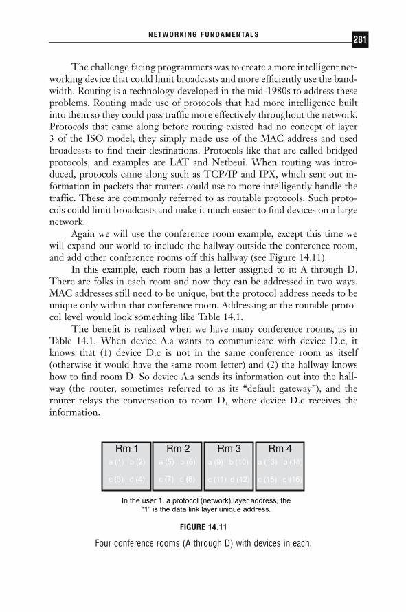
Again we will use the conference room example, except this time wewill expand our world to include the hallway outside the conference room,and add other conference rooms off this hallway (see Figure 14.11).
In this example, each room has a letter assigned to it: A through D.There are folks in each room and now they can be addressed in two ways.MAC addresses still need to be unique, but the protocol address needs to beunique only within that conference room. Addressing at the routable proto-col level would look something like Table 14.1.
The benefit is realized when we have many conference rooms, as inTable 14.1. When device A.a wants to communicate with device D.c, itknows that (1) device D.c is not in the same conference room as itself (otherwise it would have the same room letter) and (2) the hallway knowshow to find room D. So device A.a sends its information out into the hall-way (the router, sometimes referred to as its “default gateway”), and therouter relays the conversation to room D, where device D.c receives theinformation.
NETWORKING FUNDAMENTALS 281
In the user 1. a protocol (network) layer address, the“1” is the data link layer unique address.
FIGURE 14.11
Four conference rooms (A through D) with devices in each.
DRE14 11/16/2005 9:47 AM Page 281

Earlier we mentioned that there are devices that can take the spokenword and convert it to written, and the reverse, as well. Both routers andbridges are capable of doing this, and commonly do. For instance, room Ccould be a room in which all the devices are communicating via the writtenword, while rooms A, B, and D are communicating via oral speech. Therouter would know how to verbalize everything coming out of room C andgoing into the other rooms, and know how to do the reverse for traffic goinginto room C.
Routing has been tremendously beneficial in large, complicated envi-ronments. Although it adds another layer of complexity and requires signif-icantly more engineering to set up, it goes a long way toward simplifying,troubleshooting, and preventing a network from collapsing during heavytraffic. Unfortunately, routing can slow traffic down, because it has toperform some intensive tasks in order to determine exactly where the packetneeds to travel. Keeping with our analogy, the time spent using the hallwayto get to another conference room slows the conversation. In most cases theslowdown is negligible, but as we discuss in designing PACS networks, it canbe detrimental to PACS performance.
A router is slow because it has to examine more of the packet to makerouting decisions. Bridges work much more quickly because they have fewerdecisions to make. The nature of networks is such that they are never set upas efficiently as possible—the server you need so you get your informationinevitably has 2 or 3 routers in the way. In addition, as bandwidth demandsincrease, segments need to become smaller, which means more routers,which means slower response time to the server. When routing became tooslow, another technology was introduced. Enter switching.
PACS: A Guide to the Digi tal Revolut ion282
TABLE 14.1Conference Rooms and Addresses of Their Devices
Room Devices’ Addresses
A A.a, A.b, A.c, A.dB B.a, B.b, B.c, B.dC C.a, C.b, C.c, C.dD D.a, D.b, D.c, D.d
DRE14 11/16/2005 9:47 AM Page 282
SWITCHING
Switching, as simple as it is, revolutionized the networking industry. Manynetworks were collapsing under the sheer weight of routers, and engineerswere unable to break up their segments any more than they already hadwithout creating hopelessly complex architectures. The idea of switching isto step back and look at only as much of the packet as a bridge looks at, thedata link layer. This means that a switch is essentially a bridge. To a lot ofpeople this is confusing, so let us look at it this way—a switch is basically abridge with many, many interfaces, and sometimes each interface has only 1device connected to it. Switches were developed because it became cost-effective to build bridges with numerous interfaces on them. Switches areessentially bridges that are applied in a different manner than originalbridges because they are more powerful. As we begin to look at networkdesign and talk about bandwidth, we will see how the idea of switching (andthe fact that it came about as higher-speed networks were being developed),when incorporated with routing, helps make network bottlenecks easier toremove.
Switches are used in a variety of ways. Some switches are used in thecore of the network (more on this later), whereas other switches are used toreplace hubs. When they replace hubs, they have the same effect as chang-ing the rules in the conference room. Recall our first rule of the conferenceroom: anybody can talk to anybody else, but only 1 person in the room canbe talking at a time. If more than 1 person speaks we have a collision. Tohelp alleviate the problem, we first installed a bridge in the conference room;then we added conference rooms with a hallway as the router. But thatscheme can be applied only so far. At some point we cannot take everybodyout of the conference room, and 50 chatty people are going to have someserious collision problems. It does not seem productive to install 25 bridgesin the conference room. But when switching came along, it greatly simpli-fied the situation by doing just that. In effect, switching looked at the ruleswe established concerning talking and changed 1 rule in the conferenceroom—that which was the most inefficient. Switching allows us to say that anybody can talk to anybody else, as long as each person is talking toonly 1 other person. Sometimes when a switch is used to separate everybodyfrom everybody else in the conference room, it is referred to as a switchinghub.
But what happens when the users in the conference room do not wantto talk to each other, but instead want to talk to somebody in another room,that is, through the router? Then we need to talk about bandwidth.
NETWORKING FUNDAMENTALS 283
DRE14 11/16/2005 9:47 AM Page 283
BANDWIDTH
Bandwidth, simply stated, is the rate at which information can be transmit-ted in a specific time interval, usually seconds. In computer networks, therate at which data can be transmitted is measured in bits per second. A bit,or binary digit, is either a 0 or a 1. A bit can be considered the atom of thecomputer world. Eight bits are called a byte. The reason 8 bits are signifi-cant is that eight 1s in binary form (11111111) are equivalent to 255 indecimal form, which is enough to represent all variations in the Englishalphabet of upper- and lower-case letters, numbers, and other characters.
One million bytes are commonly referred to as 1 megabyte, or 1MB.This is how most computer users understand file sizes, hard drive sizes, andthe like. In the data networking world, however, transmission rates are meas-ured in megabits, not megabytes. One megabit is denoted as 1Mb to distinguish it from a megabyte. In this way, data transmission rates can bedeceiving because a network that can transmit data at 10Mb per second isreally transmitting 1.25MB per second (one eighth the speed). Whymegabytes are used when referring to file sizes and megabits are used whenreferring to data transfer rates is a mystery. It could have been a marketingploy by network vendors to make their networks sound faster than they reallyare.
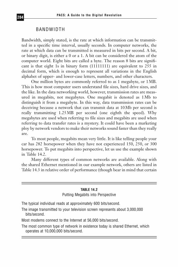
To most people, megabits mean very little. It is like telling people yourcar has 282 horsepower when they have not experienced 150, 250, or 300horsepower. To put megabits into perspective, let us use the example shownin Table 14.2.
Many different types of common networks are available. Along withthe shared Ethernet mentioned in our example network, others are listed inTable 14.3 in relative order of performance (though bear in mind that certain
PACS: A Guide to the Digi tal Revolut ion284
TABLE 14.2Putting Megabits into Perspective
The typical individual reads at approximately 600 bits/second.The image transmitted to your television screen represents about 3,000,000
bits/second.Most modems connect to the Internet at 56,000 bits/second.The most common type of network in existence today is shared Ethernet, which
operates at 10,000,000 bits/second.
DRE14 11/16/2005 9:47 AM Page 284
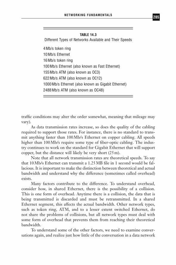
traffic conditions may alter the order somewhat, meaning that mileage mayvary).
As data transmission rates increase, so does the quality of the cablingrequired to support those rates. For instance, there is no standard to trans-mit anything faster than 100Mb/s Ethernet on copper cabling. All speedshigher than 100Mb/s require some type of fiber-optic cabling. The indus-try continues to work on the standard for Gigabit Ethernet that will supportcopper, but the distance will likely be very short (25m).
Note that all network transmission rates are theoretical speeds. To saythat 10Mb/s Ethernet can transmit a 1.25MB file in 1 second would be fal-lacious. It is important to make the distinction between theoretical and actualbandwidth and understand why the difference (sometimes called overhead)exists.
Many factors contribute to the difference. To understand overhead,consider how, in shared Ethernet, there is the possibility of a collision. This is one form of overhead. Anytime there is a collision, the data that isbeing transmitted is discarded and must be retransmitted. In a shared Ethernet segment, this affects the actual bandwidth. Other network types,such as token ring, ATM, and to a lesser extent switched Ethernet, do not share the problems of collisions, but all network types must deal withsome form of overhead that prevents them from reaching their theoreticalbandwidth.
To understand some of the other factors, we need to examine conver-sations again, and realize just how little of the conversation in a data network
NETWORKING FUNDAMENTALS 285
TABLE 14.3Different Types of Networks Available and Their Speeds
4Mb/s token ring10Mb/s Ethernet16Mb/s token ring100Mb/s Ethernet (also known as Fast Ethernet)155Mb/s ATM (also known as OC3)622Mb/s ATM (also known as OC12)1000Mb/s Ethernet (also known as Gigabit Ethernet)2488Mb/s ATM (also known as OC48)
DRE14 11/16/2005 9:47 AM Page 285
has to do with the actual data being transmitted. Each half of spoken dia-logue is made of sentences. In a network, each of these sentences is called apacket. Packets are the elements composed of bits that carry data betweenthe 2 computers on the network.
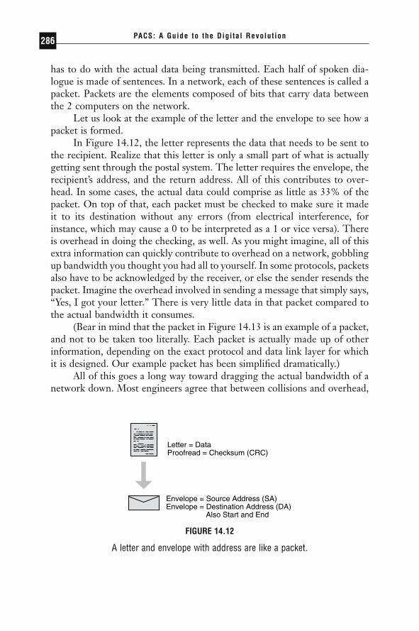
Let us look at the example of the letter and the envelope to see how apacket is formed.
In Figure 14.12, the letter represents the data that needs to be sent tothe recipient. Realize that this letter is only a small part of what is actuallygetting sent through the postal system. The letter requires the envelope, therecipient’s address, and the return address. All of this contributes to over-head. In some cases, the actual data could comprise as little as 33% of thepacket. On top of that, each packet must be checked to make sure it madeit to its destination without any errors (from electrical interference, forinstance, which may cause a 0 to be interpreted as a 1 or vice versa). Thereis overhead in doing the checking, as well. As you might imagine, all of thisextra information can quickly contribute to overhead on a network, gobblingup bandwidth you thought you had all to yourself. In some protocols, packetsalso have to be acknowledged by the receiver, or else the sender resends thepacket. Imagine the overhead involved in sending a message that simply says,“Yes, I got your letter.” There is very little data in that packet compared tothe actual bandwidth it consumes.
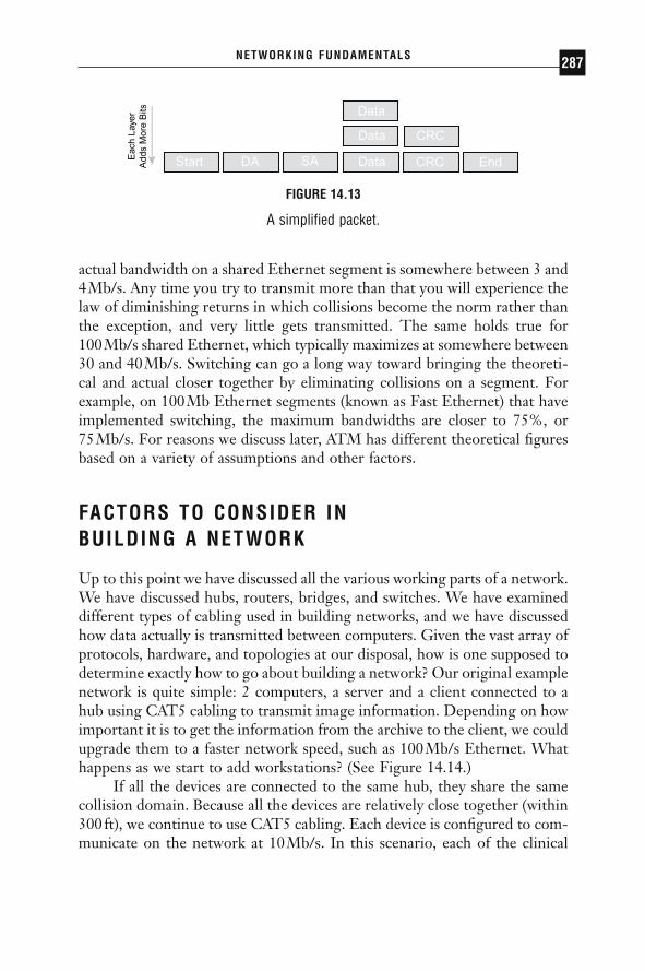
(Bear in mind that the packet in Figure 14.13 is an example of a packet,and not to be taken too literally. Each packet is actually made up of otherinformation, depending on the exact protocol and data link layer for whichit is designed. Our example packet has been simplified dramatically.)
All of this goes a long way toward dragging the actual bandwidth of anetwork down. Most engineers agree that between collisions and overhead,
PACS: A Guide to the Digi tal Revolut ion286
Letter = DataProofread = Checksum (CRC)
Envelope = Source Address (SA)Envelope = Destination Address (DA) Also Start and End
FIGURE 14.12
A letter and envelope with address are like a packet.
DRE14 11/16/2005 9:47 AM Page 286
actual bandwidth on a shared Ethernet segment is somewhere between 3 and4Mb/s. Any time you try to transmit more than that you will experience thelaw of diminishing returns in which collisions become the norm rather thanthe exception, and very little gets transmitted. The same holds true for 100Mb/s shared Ethernet, which typically maximizes at somewhere between30 and 40Mb/s. Switching can go a long way toward bringing the theoreti-cal and actual closer together by eliminating collisions on a segment. Forexample, on 100Mb Ethernet segments (known as Fast Ethernet) that haveimplemented switching, the maximum bandwidths are closer to 75%, or 75Mb/s. For reasons we discuss later, ATM has different theoretical figuresbased on a variety of assumptions and other factors.
FACTORS TO CONSIDER IN BUILDING A NETWORK
Up to this point we have discussed all the various working parts of a network.We have discussed hubs, routers, bridges, and switches. We have examineddifferent types of cabling used in building networks, and we have discussedhow data actually is transmitted between computers. Given the vast array ofprotocols, hardware, and topologies at our disposal, how is one supposed todetermine exactly how to go about building a network? Our original examplenetwork is quite simple: 2 computers, a server and a client connected to ahub using CAT5 cabling to transmit image information. Depending on howimportant it is to get the information from the archive to the client, we couldupgrade them to a faster network speed, such as 100Mb/s Ethernet. Whathappens as we start to add workstations? (See Figure 14.14.)
If all the devices are connected to the same hub, they share the samecollision domain. Because all the devices are relatively close together (within300ft), we continue to use CAT5 cabling. Each device is configured to com-municate on the network at 10Mb/s. In this scenario, each of the clinical
NETWORKING FUNDAMENTALS 287
Eac
h La
yer
Add
s M
ore
Bits
FIGURE 14.13
A simplified packet.
DRE14 11/16/2005 9:47 AM Page 287
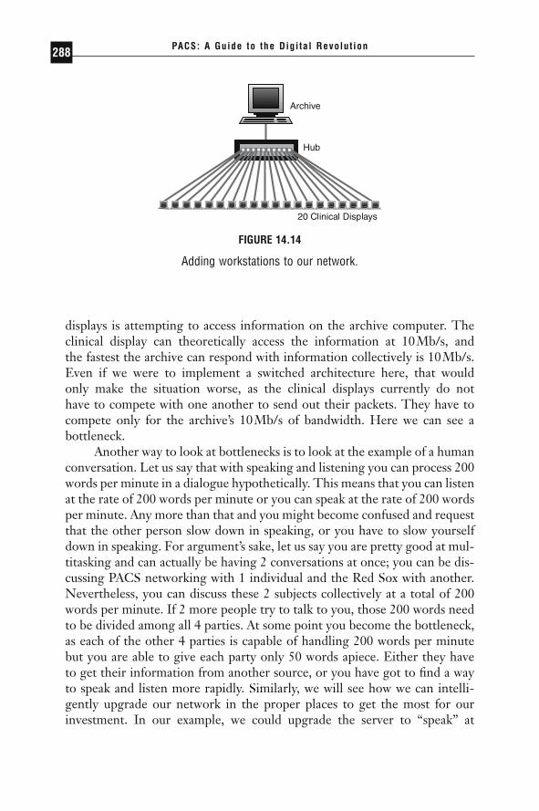
displays is attempting to access information on the archive computer. Theclinical display can theoretically access the information at 10Mb/s, and the fastest the archive can respond with information collectively is 10Mb/s.Even if we were to implement a switched architecture here, that would only make the situation worse, as the clinical displays currently do not have to compete with one another to send out their packets. They have tocompete only for the archive’s 10Mb/s of bandwidth. Here we can see a bottleneck.
Another way to look at bottlenecks is to look at the example of a humanconversation. Let us say that with speaking and listening you can process 200words per minute in a dialogue hypothetically. This means that you can listenat the rate of 200 words per minute or you can speak at the rate of 200 wordsper minute. Any more than that and you might become confused and requestthat the other person slow down in speaking, or you have to slow yourselfdown in speaking. For argument’s sake, let us say you are pretty good at mul-titasking and can actually be having 2 conversations at once; you can be dis-cussing PACS networking with 1 individual and the Red Sox with another.Nevertheless, you can discuss these 2 subjects collectively at a total of 200words per minute. If 2 more people try to talk to you, those 200 words needto be divided among all 4 parties. At some point you become the bottleneck,as each of the other 4 parties is capable of handling 200 words per minutebut you are able to give each party only 50 words apiece. Either they haveto get their information from another source, or you have got to find a wayto speak and listen more rapidly. Similarly, we will see how we can intelli-gently upgrade our network in the proper places to get the most for ourinvestment. In our example, we could upgrade the server to “speak” at
PACS: A Guide to the Digi tal Revolut ion288
FIGURE 14.14
Adding workstations to our network.
DRE14 11/16/2005 9:47 AM Page 288
100Mb/s Ethernet, while keeping the clinical displays at 10Mb/s Ethernet.Upgrading all the clinical displays to 100Mb/s Ethernet while the archiveprocesses at 100Mb/s will accomplish little except in an environment whereonly 1 or 2 clinical displays are requesting information at once, in which caseoptimum transmission rates can still be realized. If multiple workstations areoperating at 100Mb/s and requesting data from the archive, the archivecould again become the bottleneck, at which time we could upgrade it toGigabit Ethernet or ATM of one type or another.
It is clear there are multiple ways to handle this arms race. In the nextexample, we begin to integrate the various devices and architectures into acoherent PACS solution.
A REAL-WORLD EXAMPLE
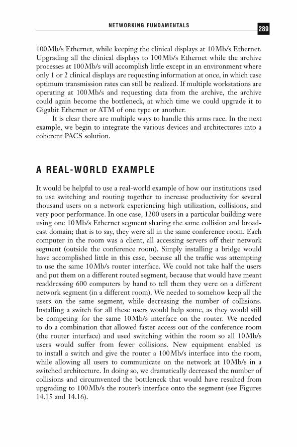
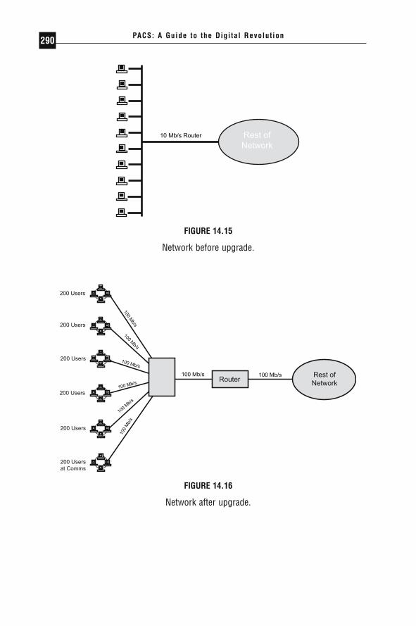
It would be helpful to use a real-world example of how our institutions usedto use switching and routing together to increase productivity for severalthousand users on a network experiencing high utilization, collisions, andvery poor performance. In one case, 1200 users in a particular building wereusing one 10Mb/s Ethernet segment sharing the same collision and broad-cast domain; that is to say, they were all in the same conference room. Eachcomputer in the room was a client, all accessing servers off their networksegment (outside the conference room). Simply installing a bridge wouldhave accomplished little in this case, because all the traffic was attemptingto use the same 10Mb/s router interface. We could not take half the usersand put them on a different routed segment, because that would have meantreaddressing 600 computers by hand to tell them they were on a differentnetwork segment (in a different room). We needed to somehow keep all theusers on the same segment, while decreasing the number of collisions.Installing a switch for all these users would help some, as they would still be competing for the same 10Mb/s interface on the router. We needed to do a combination that allowed faster access out of the conference room(the router interface) and used switching within the room so all 10Mb/s users would suffer from fewer collisions. New equipment enabled us to install a switch and give the router a 100Mb/s interface into the room,while allowing all users to communicate on the network at 10Mb/s in aswitched architecture. In doing so, we dramatically decreased the number ofcollisions and circumvented the bottleneck that would have resulted fromupgrading to 100Mb/s the router’s interface onto the segment (see Figures14.15 and 14.16).
NETWORKING FUNDAMENTALS 289
DRE14 11/16/2005 9:47 AM Page 289
PACS: A Guide to the Digi tal Revolut ion290
10 Mb/s Router
FIGURE 14.15
Network before upgrade.
100 Mb/s100 Mb/s
100 Mb/s
100 Mb/s
100 Mb/s
100 Mb/s
100 Mb/s
100
Mb/
s
FIGURE 14.16
Network after upgrade.
DRE14 11/16/2005 9:47 AM Page 290
PACS NETWORKS
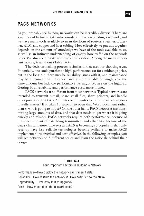
As you probably see by now, networks can be incredibly diverse. There area number of factors to take into consideration when building a network, andwe have many tools available to us in the form of routers, switches, Ether-net, ATM, and copper and fiber cabling. How effectively we put this togetherdepends on the amount of knowledge we have of the tools available to us,as well as an intimate understanding of exactly how traffic on the networkflows. We also need to take cost into consideration. Among the many impor-tant factors, 4 stand out (Table 14.4).
The decision-making process is similar to that used for choosing a car.Potentially, one could purchase a high-performance car for a midrange price,but in the long run there may be reliability issues with it, and maintenancemay be expensive. On the other hand, a more reliable car might cost thesame amount but lack the performance we might require on the highway.Getting both reliability and performance costs more money.
PACS networks are different from most networks. Typical networks areintended to transmit e-mail, share small files, share printers, and handleother processes. If it takes 2 minutes or 3 minutes to transmit an e-mail, doesit really matter? If it takes 10 seconds to open that Word document ratherthan 8, who is going to notice? On the other hand, PACS networks are trans-mitting large amounts of data, and that data needs to get where it is goingquickly and reliably. PACS networks require both performance, because ofthe sheer amount of data being transmitted, and reliability, because of thedata’s clinical nature. The reason PACS is becoming so popular is that onlyrecently have fast, reliable technologies become available to make PACSimplementations practical and cost-effective. In the following examples, youwill see networks on 3 different scales and learn the rationale behind theirdesign.
NETWORKING FUNDAMENTALS 291
TABLE 14.4Four Important Factors in Building a Network
Performance—How quickly the network can transmit data.Reliability—How reliable the network is. How easy is it to maintain?Upgradability—How easy is it to upgrade?Price—How much does the network cost?
DRE14 11/16/2005 9:47 AM Page 291
ASYNCHRONOUS TRANSFER MODE
First let us look at few technologies that we will use in building this network.One such technology is ATM, or asynchronous transfer mode. We willexplain the differences between ATM and Ethernet by explaining how theywere derived.
Ethernet, in its purest form, is a “dumb” medium. It does not knowwhat traffic is passing over it, nor does it need to. It operates under simplerules and principles that govern how traffic will be transported. Your e-mailabout the Red Sox has no higher or lower priority than a PACS image or atelephone call. In this sense, Ethernet is said to have no concept of qualityof service, or QoS.
ATM, on the other hand, was designed with the intent of allowing thenetwork administrator to classify different types of traffic with different pri-orities. In this sense, an ATM network offers different levels of QoS depend-ing on the application or workstation.
ATM is able to do this so well in large part because it is a much morepredictive architecture. In an Ethernet network, packets can vary in size,reaching a maximum of 1500 bytes. However, some packets can be 300 bytes,some 50 bytes, and some 1500 bytes. Thus, it is very difficult for an Ether-net network to be able to predict traffic patterns. On the other hand, ATMpackets are called “cells” and are always 53 bytes in length. Because of theconstant size of the cells, ATM is predictive: a packet of streaming video willnot get “stuck” behind a 1500-byte e-mail packet in a router while it tries toreach its destination.
ATM is often compared to a telephone network because of the highpredictability it ensures. ATM networks can be built so that voice cells willhave a high priority and always get through. ATM does this in much thesame way the telephone system does. When you pick up the telephone and attempt to make a call, the ATM or telephone network checks to seewhether it can complete the call with the parameters you require. In the case of ATM and computer networks, you may request a certain amount of bandwidth. If the ATM network cannot guarantee that amount of bandwidth, the computer and the network can negotiate a lower bandwidthrate, or not start the conversation at all. This is very much like a telephonecall, especially a cell phone call, where you occasionally get a “fast busy”because the voice network cannot guarantee enough bandwidth to completethe call.
That said, ATM has had a long, troubled journey toward universalacceptance. It has taken years from its inception to make it to a finishedproduct. Along the way various vendors have released products based
PACS: A Guide to the Digi tal Revolut ion292
DRE14 11/16/2005 9:47 AM Page 292
only loosely on not-yet-agreed-upon standards that make vendor interoper-ability very unlikely. Because of this, when you choose an ATM vendor,understand the high probability of the product’s not working with otherATM hardware.
Another consideration in choosing to use ATM in networks is the worka router or switch needs to perform in converting packets into cells and back.This conversion contributes a certain overhead, which is often viewed asdetrimental. Strong consideration should be made when mixing ATM withother network types, such as Ethernet. However, those considerations gobeyond the scope of this book.
There are other downsides to ATM. The number of ATM installationsin most LAN environments is rather small when compared to those of Ethernet. Hence, it can be harder to find engineers who have expertise inthe area. What is more, the price per port of ATM is significantly higherthan that of Ethernet. Add to this the fact that Gigabit Ethernet is begin-ning to gain steam and provide high bandwidth at a lower price, so an invest-ment in ATM may not be a good one.
WIDE AREA NETWORKING
All the technologies that we have talked about so far (ATM, Ethernet, tokenring) have been designed for local campus settings; that is, for connectionson which we can run either fiber or copper cabling. When we leave thecampus setting, however, we no longer have the luxury of being able to runour own cable. Whether trying to go across the street, across town, or acrossthe world, we need an external provider to connect sites. Telephone com-panies (also known as Regional Bell Operating Companies, or RBOCs), suchas Bell Atlantic or AT&T, have massive networks designed for handling tele-phone calls all over the world. They can use these networks to provide datatransmission as well.
RBOCs lease “circuits” to companies over which to transmit data.These circuits are generally point-to-point connections between 2 sites.Generally speaking, the circuits they provide offer bandwidth from 56 kilo-bits (Kb)/s all the way up to 155Mb/s. Unfortunately, charges are recurring(usually monthly), and the price per megabit is much higher than on the localarea network (LAN) for a connection of the same speed. For instance, a stan-dard type of circuit, a T1, operates at 1.554Mb/s, and can cost severalhundred dollars per month. The farther the circuit extends, the more theRBOC charges. Several factors in the industry have kept these costs fairlystable for many years, but technologies to get around these charges are
NETWORKING FUNDAMENTALS 293
DRE14 11/16/2005 9:47 AM Page 293
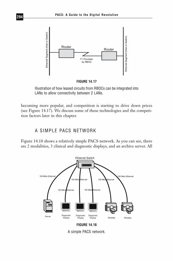
becoming more popular, and competition is starting to drive down prices(see Figure 14.17). We discuss some of these technologies and the competi-tion factors later in this chapter.
A SIMPLE PACS NETWORK
Figure 14.18 shows a relatively simple PACS network. As you can see, thereare 2 modalities, 3 clinical and diagnostic displays, and an archive server. All
PACS: A Guide to the Digi tal Revolut ion294
Eth
erne
t Seg
men
t (H
ub o
r S
witc
h)
Eth
erne
t Seg
men
t (H
ub o
r S
witc
h)
FIGURE 14.17
Illustration of how leased circuits from RBOCs can be integrated intoLANs to allow connectivity between 2 LANs.
100 Mb/s Ethernet
100 Mb/s Ethernet
100 Mb/s Ethernet
100 Mb/s Ethernet
100 Mb/s Ethernet
100 Mb/s Ethernet
FIGURE 14.18
A simple PACS network.
DRE14 11/16/2005 9:47 AM Page 294
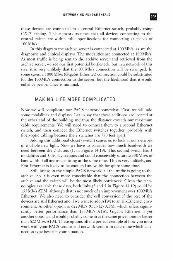
these devices are connected to a central Ethernet switch, probably usingCAT5 cabling. This network assumes that all devices connecting to thecentral switch are within cable specifications for connecting at speeds of 100Mb/s.
In this diagram the archive server is connected at 100Mb/s, as are thediagnostic and clinical displays. The modalities are connected at 100Mb/s.As most traffic is being sent to the archive server and retrieved from thearchive server, we see our first potential bottleneck, but in a network of thissize, it is very unlikely that the 100Mb/s connection will be swamped. Insome cases, a 1000Mb/s (Gigabit Ethernet) connection could be substitutedfor the 100Mb/s connection to the server, but the likelihood that it wouldenhance performance is minimal.
MAKING LIFE MORE COMPLICATED
Now we will complicate our PACS network somewhat. First, we will addsome modalities and displays. Let us say that these additions are located atthe other end of the building and thus the distance exceeds our maximumcable requirements. We will need to connect them to a second Ethernetswitch, and then connect the Ethernet switches together, probably withfiber-optic cabling because the 2 switches are 750 feet apart.
Adding this additional closet (switch) causes us to look at our networkin a whole new light. Now we have to consider how much bandwidth weneed between the 2 closets (1, in Figure 14.19). This second switch has 3modalities and 3 display stations and could conceivably saturate 330Mb/s ofbandwidth if all are transmitting at the same time. This is very unlikely, andFast Ethernet is likely to be enough bandwidth for quite some time.
Still, just as in the simple PACS network, all the traffic is going to thearchive. So it is even more conceivable that the connection between thearchive and the switch will be the most likely bottleneck. Given the tech-nologies available these days, both links (2 and 3 in Figure 14.19) could be155Mb/s ATM, although that is not much of an improvement over 100Mb/sEthernet. We also need to consider the cell conversion if the rest of thedevices are still Ethernet and if we want to add ATM to an all-Ethernet envi-ronment. Another option is 622Mb/s (OC-12) ATM, which offers signifi-cantly better performance than 155Mb/s ATM. Gigabit Ethernet is yetanother option, and would probably come in at the same price point or betterthan 622Mb/s ATM. These options offer a perfect example of how you mustwork with your PACS vendor and network vendor to determine which con-nection type best fits your situation.
NETWORKING FUNDAMENTALS 295
DRE14 11/16/2005 9:47 AM Page 295
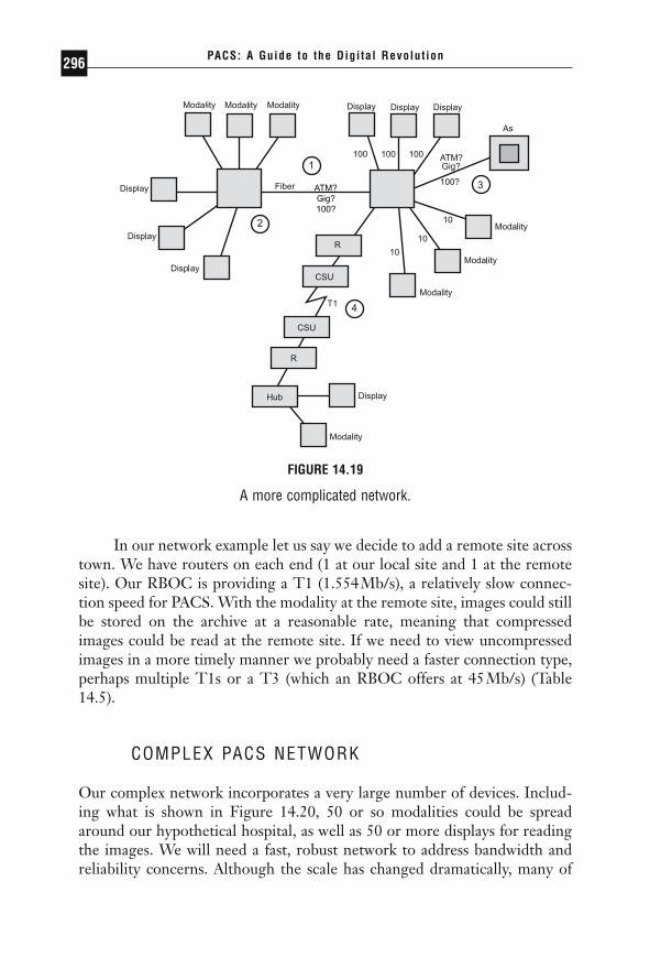
In our network example let us say we decide to add a remote site acrosstown. We have routers on each end (1 at our local site and 1 at the remotesite). Our RBOC is providing a T1 (1.554Mb/s), a relatively slow connec-tion speed for PACS. With the modality at the remote site, images could stillbe stored on the archive at a reasonable rate, meaning that compressedimages could be read at the remote site. If we need to view uncompressedimages in a more timely manner we probably need a faster connection type,perhaps multiple T1s or a T3 (which an RBOC offers at 45Mb/s) (Table14.5).
COMPLEX PACS NETWORK
Our complex network incorporates a very large number of devices. Includ-ing what is shown in Figure 14.20, 50 or so modalities could be spreadaround our hypothetical hospital, as well as 50 or more displays for readingthe images. We will need a fast, robust network to address bandwidth andreliability concerns. Although the scale has changed dramatically, many of
PACS: A Guide to the Digi tal Revolut ion296
ATM?Gig?100?
FIGURE 14.19
A more complicated network.
DRE14 11/16/2005 9:47 AM Page 296
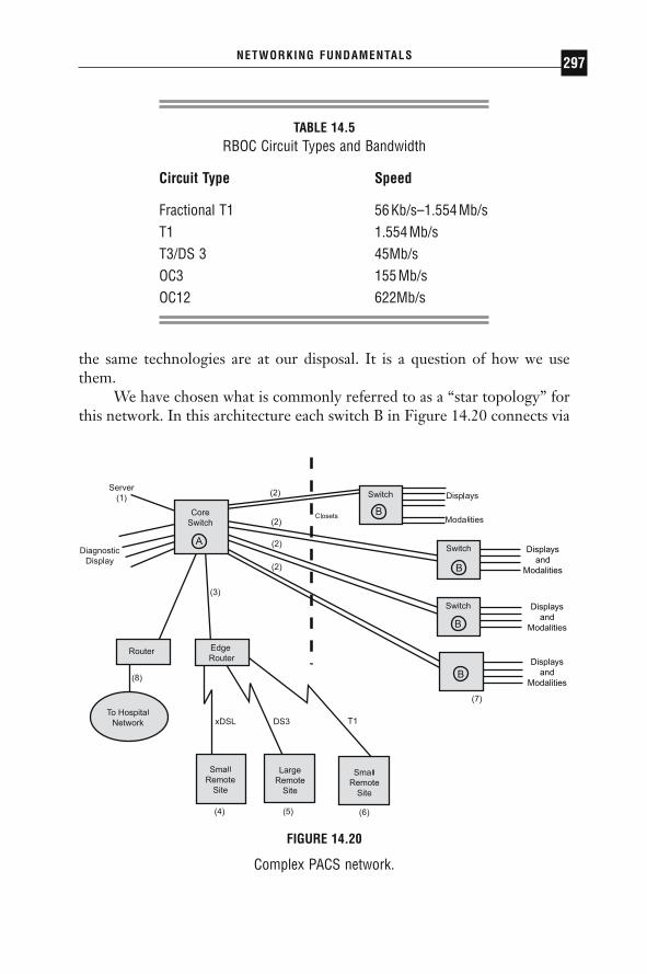
the same technologies are at our disposal. It is a question of how we usethem.
We have chosen what is commonly referred to as a “star topology” forthis network. In this architecture each switch B in Figure 14.20 connects via
NETWORKING FUNDAMENTALS 297
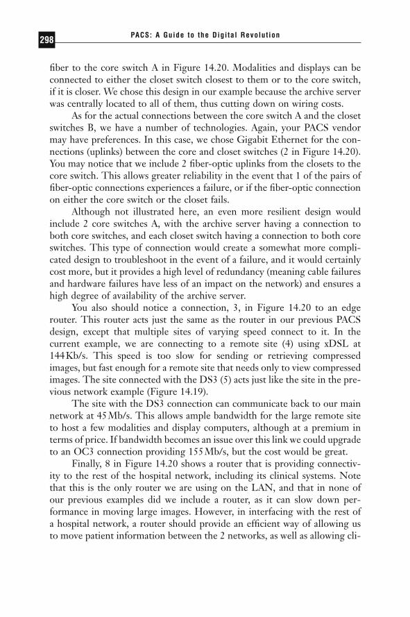
TABLE 14.5RBOC Circuit Types and Bandwidth
Circuit Type Speed
Fractional T1 56Kb/s–1.554Mb/sT1 1.554Mb/sT3/DS 3 45Mb/sOC3 155Mb/sOC12 622Mb/s
Displaysand
Modalities
Displaysand
Modalities
Displaysand
Modalities
FIGURE 14.20
Complex PACS network.
DRE14 11/16/2005 9:47 AM Page 297
fiber to the core switch A in Figure 14.20. Modalities and displays can beconnected to either the closet switch closest to them or to the core switch,if it is closer. We chose this design in our example because the archive serverwas centrally located to all of them, thus cutting down on wiring costs.
As for the actual connections between the core switch A and the closetswitches B, we have a number of technologies. Again, your PACS vendormay have preferences. In this case, we chose Gigabit Ethernet for the con-nections (uplinks) between the core and closet switches (2 in Figure 14.20).You may notice that we include 2 fiber-optic uplinks from the closets to thecore switch. This allows greater reliability in the event that 1 of the pairs offiber-optic connections experiences a failure, or if the fiber-optic connectionon either the core switch or the closet fails.
Although not illustrated here, an even more resilient design wouldinclude 2 core switches A, with the archive server having a connection toboth core switches, and each closet switch having a connection to both coreswitches. This type of connection would create a somewhat more compli-cated design to troubleshoot in the event of a failure, and it would certainlycost more, but it provides a high level of redundancy (meaning cable failuresand hardware failures have less of an impact on the network) and ensures ahigh degree of availability of the archive server.
You also should notice a connection, 3, in Figure 14.20 to an edgerouter. This router acts just the same as the router in our previous PACSdesign, except that multiple sites of varying speed connect to it. In thecurrent example, we are connecting to a remote site (4) using xDSL at 144Kb/s. This speed is too slow for sending or retrieving compressedimages, but fast enough for a remote site that needs only to view compressedimages. The site connected with the DS3 (5) acts just like the site in the pre-vious network example (Figure 14.19).
The site with the DS3 connection can communicate back to our mainnetwork at 45Mb/s. This allows ample bandwidth for the large remote siteto host a few modalities and display computers, although at a premium interms of price. If bandwidth becomes an issue over this link we could upgradeto an OC3 connection providing 155Mb/s, but the cost would be great.
Finally, 8 in Figure 14.20 shows a router that is providing connectiv-ity to the rest of the hospital network, including its clinical systems. Notethat this is the only router we are using on the LAN, and that in none ofour previous examples did we include a router, as it can slow down per-formance in moving large images. However, in interfacing with the rest ofa hospital network, a router should provide an efficient way of allowing usto move patient information between the 2 networks, as well as allowing cli-
PACS: A Guide to the Digi tal Revolut ion298
DRE14 11/16/2005 9:47 AM Page 298

nicians to view compressed images throughout the hospital on lower-pricedworkstations.
FUTURE TRENDS
The networking industry as a whole experiences changes at an extremelyrapid pace. The rate of change is dizzying. There are several changes in theindustry that will affect how PACS is implemented in the near future.
GIGABIT ETHERNET
Gigabit Ethernet has gained acceptance. Now Gigabit Ethernet is offeredby nearly all vendors at reasonable prices. For the first time on the LAN,the ability for the network to provide inexpensive bandwidth has outpacedthe computer’s ability to transmit data. This means that since it is difficultfor a Sparc workstation to transmit much more than 200Mb/s, a GigabitEthernet connection offers plenty of bandwidth. Before Gigabit Ethernet,only expensive OC-12 ATM could make such a promise, while most work-stations could saturate a 100Mb/s Ethernet pipe. Of course, as computersget faster, their ability to transmit data will also increase. At this point,however, Gigabit Ethernet provides a lot of room for growth. Even so, it ispossible for computers to collectively saturate Gigabit Ethernet backbonesand connections, so careful network design is still required. Further, thereare groups currently working on terabit Ethernet speed solutions.
RESOURCE RESERVATION PROTOCOL
Earlier, when explaining the advantages of ATM, we said that ATM had theability to distinguish between different traffic types, thus allowing it to effi-ciently pass video and voice traffic while still moving e-mail along at a rea-sonable rate. Ethernet vendors, not wanting to be left in the dust, recognizedthis distinguishing capability as an important feature and have been workingtoward implementing some of those features into the Ethernet architecture.Called RSVP (resource reservation protocol), this feature will give Ethernetsome ATM-like capabilities by allowing it to offer a lesser degree of QoS(almost a poor man’s QoS). When combined with the brute force of GigabitEthernet, it offers a challenge to the future of the more elegant ATM in theLAN environment.
NETWORKING FUNDAMENTALS 299
DRE14 11/16/2005 9:47 AM Page 299
LAYER 3 SWITCHING
As detailed at length earlier in this chapter, switching occurs at the ISOmodel layer 2 and routing occurs at layer 3. The lines are becoming blurred,however, as vendors seek to offer the speed and flexibility of switching andthe intelligence and efficiency of routing. Vendors are calling this layer 3switching, although different vendors have widely varying ideas of how toimplement it and what it means. In effect, layer 3 switching should combinethe best of both worlds to such an extent that the idea of using the corridorin the conference room model will no longer be seen as an impediment to fast, efficient communication between different segments. In a largenetwork, where PACS seeks to peacefully coexist with any number of appli-cations, layer 3 switching offers potentially dramatic benefits by getting largeimages and studies out to a vast clientele.
VIRTUAL PRIVATE NETWORKS
Virtual private networks, or VPNs, have constituted a major buzzword inthe industry. The goal of this technology is to make the Internet a safemedium for the secure transfer of private information, such as clinical dataor images. It does this by encrypting the information at the source anddecrypting it at the destination. In doing so a private virtual network is setup over the public, unsecure Internet. There is hope that companies can usethis technology to decrease costs by using the Internet to exchange infor-mation that they normally would be able to share only over private circuitsleased from RBOCs, thus saving money. This is also an ideal technology touse for remote access to the corporate network for home users or in virtualoffice environments. In the near future, as this technology matures andvendors are able to produce scalable solutions, VPNs will make a greatimpact on how the Internet is used.
LOWER COSTS
Competitiveness among vendors also means lower costs in the networkingindustry, just as in the computer industry. In the first year that Gigabit Ethernet became available, prices dropped nearly in half. The price of NICscontinues to drop, as well as the price of routers and switches. On the WANfront, RBOCs are seeing increasing competition from one another, fromcable providers, and from other third-party providers who are seeking to take
PACS: A Guide to the Digi tal Revolut ion300
DRE14 11/16/2005 9:47 AM Page 300
advantage of the tremendous hunger for bandwidth on the WAN. The costand speed of the connection to the home or remote office, often called the“last mile,” is quickly reaching attractive price points for many applications,especially PACS. RBOCs will be forced to lower prices of T1s and T3s asnew technologies such as cable modems, xDSL, and wireless become morecommon. Similarly, use of the Internet and technologies such as VPN willalso allow for significant price reductions for remote access.
NETWORKING FUNDAMENTALS 301
DRE14 11/16/2005 9:47 AM Page 301