user guide - taoglas
TRANSCRIPT

EDGE Connect™
Next-generation IoT device and software platform
Taoglas EDGE Connect™ next-generation IoT device and software platform set up instructions
www.taoglas.com
User Guide
IG-20-08-003-A
IG-20-08-003-A 2
EDGE Connect™
Next-generation IoT device and software platformUser GuideContents
1. Introduction 3
1.1 What’s in the Box? 3
1.2 Support 3
2. Set Up 4
2.1 Device Startup: 4
2.2 Account Setup 4
2.3 Activating your Device 5
3. Using the EDGE Connect 7
3.1 Device Overview 7
4. Using EDGE Insights 8
4.1 Insights Navigation 8
4.2 Device Management 9
4.3 Dashboard 10
4.4 Sensor Notification Rules 11
4.5 Add New Users 15
4.6 Support 16
5. Appendix 17
5.1 FAQ 17
5.2 Security 17
5.3 Safety and Regulatory Requirements 17

IG-20-08-003-A 3
The Taoglas EDGE Connect™ enables real time insights and intelligence to help your enterprise save costs, increase revenue and enhance compliance. It is a next-generation IoT device with cellular, Bluetooth, and on-board sensor capabilities with a cloud based connectivity and device management platform.
1.1 What’s in the Box?
1. Taoglas EDGE Connect
2. Micro-USB Cable
3. USB Power Supply - US Version (Regional adapters supplied with other SKU’s)
4. Taoglas EDGE Insights Activation Card
4
1 2 3
1.2 Support
For technical support please contact [email protected]
1. Go to https://www.taoglas.com/product/edge-connect to access
a. Datasheet
b. User Guides
1. Introduction

IG-20-08-003-A 4
2. Set Up2.1 Device Startup:
1. To power on the EDGE Connect press the Power Button once.
2. The EDGE Connect should be fully charged before use, using the provided power supply. When you plug the EDGE Connect into the provided USB power supply, the USB Power LED will illuminate. If the EDGE Connect requires charging, the Charge Status LED will illuminate, otherwise the Charge Status LED will remain off. The EDGE Connect is not intended to be charged using a computer USB.
3. Once powered on and initialised, the User LED will flash white 3 times.
4. At this stage you can check the battery level by pressing the Power Button once. The User LED will blink a number of times according to the battery level. Find more information on this in the Device Overview section below.
5. The device will start uploading to EDGE Insights straight away. To view any uploaded samples, you will need to register an account and activate your device on connect.taoglas.com.
2.2 Account Setup
1. To create an EDGE Insights account for your EDGE Connect devices, navigate to connect.taoglas.com and click on ‘Sign Up’.
2. Create a username and enter your details.
PowerButton
Charge Status LED
User LED
IG-20-08-003-A 5
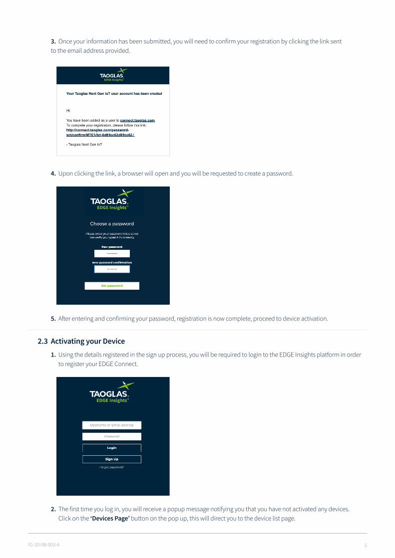
3. Once your information has been submitted, you will need to confirm your registration by clicking the link sent to the email address provided.
4. Upon clicking the link, a browser will open and you will be requested to create a password.
5. After entering and confirming your password, registration is now complete, proceed to device activation.
2.3 Activating your Device
1. Using the details registered in the sign up process, you will be required to login to the EDGE Insights platform in order to register your EDGE Connect.
2. The first time you log in, you will receive a popup message notifying you that you have not activated any devices. Click on the ‘Devices Page’ button on the pop up, this will direct you to the device list page.

IG-20-08-003-A 6
3. To activate your EDGE Connect, click ‘Activate New Device’ at the bottom of the page, a popup window will request your EDGE Connect S/N and Activation Code. After entering these, click ‘Submit’ to finish the activation process. The EDGE Connect S/N and Activation Code can be found on the card included in the box.
4. After entering the EDGE Connect S/N and Activation Code, click ‘Submit’ to activate your EDGE Connect.
5. The EDGE Connect will now be listed on the devices page, see an example of this below.
6. If device activation fails please contact Taoglas IoT support at [email protected]

IG-20-08-003-A 7
3. Using the EDGE Connect3.1 Device Overview
The EDGE Connect has 2 buttons and 3 LED’s. See the diagram below for an overview of the LED’s and buttons.
• To power on the EDGE Connect, push the Power Button once. When the EDGE Connect is powered on and has successfully initialised, the User LED will flash white 3 times in quick succession.
• To power off the EDGE Connect, hold the Power Button, while the EDGE Connect is powering down the User LED will
blink red continuously. The User LED will stop blinking when the EDGE Connect has completely powered off.
• When you plug the EDGE Connect into the provided USB Power supply, the USB Power LED will illuminate. If the EDGE Connect requires charging, the Charge Status LED will illuminate, otherwise the Charge Status LED will remain off.
• Once powered, the EDGE Connect will automatically connect to EDGE insights to gather configuration information. The EDGE Connect will continue to operate at the sampling and upload intervals set on EDGE Insights, for more information on these intervals see Device Management Section.
• The EDGE Connect can be forced into making a connection with EDGE Insights outside of the upload interval using either of the following methods:
• A single press of the Power Button, followed by a single press of the User Button will trigger the EDGE Connect to connect to EDGE Insights and gather new configuration information.
• A single press of the Power Button, followed by a longer push of the User Button (more than 4 seconds) will trigger the EDGE Connect to sample all configured sensors and upload them to EDGE Insights.• The EDGE Connect uploads its battery level to EDGE Insights, however, the battery status can also be checked by
pushing the Power Button once. This will cause the User LED to flash red a number of times according to the battery level, as per the table below:
20% 1 Flash
40% 2 Flashes
60% 3 Flashes
80% 4 Flashes
100% 5 Flashes
User ButtonPowerButton
USB Power LED
Light Sensor
USB Port
Charge Status LED
User LED
IG-20-08-003-A 8
4. Using EDGE Insights4.1 Insights Navigation
1. When you login to your account, you will land on the Dashboard page. For instructions on activating an EDGE Connect on your account, please refer to the Activating your Device section.
2. You can use the links on the top of EDGE Insights interface to navigate between your dashboard, device list page and account management pages.
a. Dashboard will bring you to your dashboard where you can see all the sensor data uploaded by your EDGE Connect.
b. Devices will bring you to your device list page, from here you can manage each of the devices you have activated on your account.
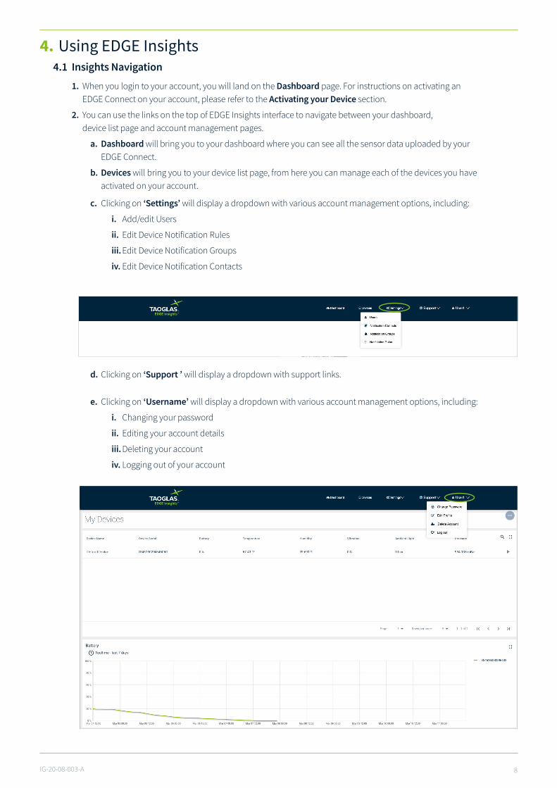
c. Clicking on ‘Settings’ will display a dropdown with various account management options, including:
i. Add/edit Users
ii. Edit Device Notification Rules
iii. Edit Device Notification Groups
iv. Edit Device Notification Contacts
e. Clicking on ‘Username’ will display a dropdown with various account management options, including:
i. Changing your password
ii. Editing your account details
iii. Deleting your account
iv. Logging out of your account
d. Clicking on ‘Support ’ will display a dropdown with support links.
IG-20-08-003-A 9
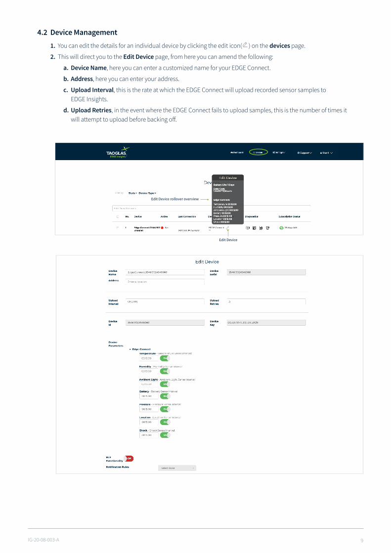
4.2 Device Management
1. You can edit the details for an individual device by clicking the edit icon( ) on the devices page.
2. This will direct you to the Edit Device page, from here you can amend the following:
a. Device Name, here you can enter a customized name for your EDGE Connect.
b. Address, here you can enter your address.
c. Upload Interval, this is the rate at which the EDGE Connect will upload recorded sensor samples to EDGE Insights.
d. Upload Retries, in the event where the EDGE Connect fails to upload samples, this is the number of times it will attempt to upload before backing off.
Edit Device rollover overview
Edit Device
IG-20-08-003-A 10
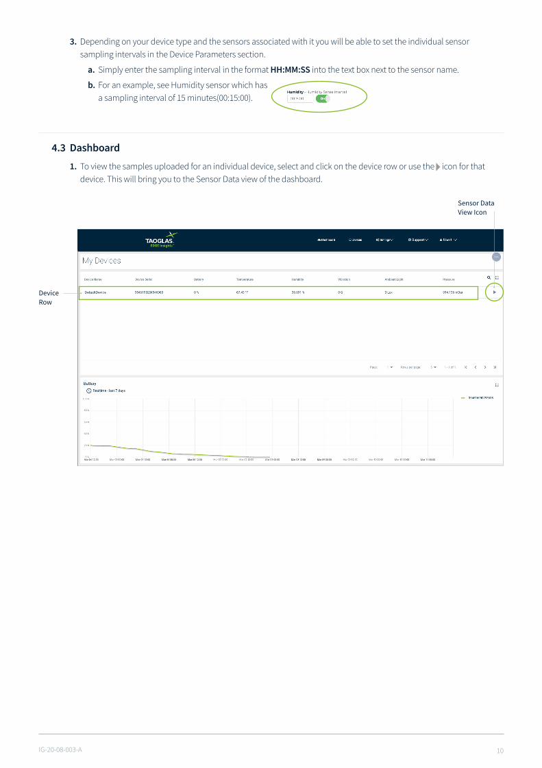
3. Depending on your device type and the sensors associated with it you will be able to set the individual sensor sampling intervals in the Device Parameters section.
a. Simply enter the sampling interval in the format HH:MM:SS into the text box next to the sensor name.
b. For an example, see Humidity sensor which has a sampling interval of 15 minutes(00:15:00).
4.3 Dashboard
1. To view the samples uploaded for an individual device, select and click on the device row or use the icon for that device. This will bring you to the Sensor Data view of the dashboard.
Sensor Data View Icon
DeviceRow

IG-20-08-003-A 11
2. Realtime and historic sensor data for each of your devices can be viewed on the dashboard tab of EDGE Insights.
3. The sensor data view of the dashboard allows you to:
a. View the latest sensor samples uploaded from your EDGE Connect (Green panels at the top).
b. View plots of sensor data over a period of time.
c. Download historical sensor data by clicking the download icon( ) at the top right of each plot, this will download the data as comma-separated values.
d. By clicking on the ( ) icon on the Temperature data chart you can alternate between Farrenheit and Celsius.
4.4 SensorNotificationRules
1. EDGE Insights allows you to notify a group of contacts based on an uploaded sensor value.
2. To do this you will first have to add a contact to EDGE Insights, click ‘Settings’ followed by ‘NotificationContacts’ at the top of the screen.
3. A page listing all the contacts associated with your account will appear, this will be empty if no contacts have been added. Click the ‘Add New Contact’ button.
IG-20-08-003-A 12
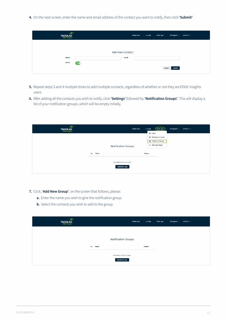
4. On the next screen, enter the name and email address of the contact you want to notify, then click ‘Submit’.
5. Repeat steps 3 and 4 multiple times to add multiple contacts, regardless of whether or not they are EDGE Insights users.
6. After adding all the contacts you wish to notify, click ‘Settings’ followed by ‘NotificationGroups’. This will display a list of your notification groups, which will be empty initially.
7. Click, ‘Add New Group’, on the screen that follows, please:
a. Enter the name you wish to give the notification group
b. Select the contacts you wish to add to the group.
IG-20-08-003-A 13
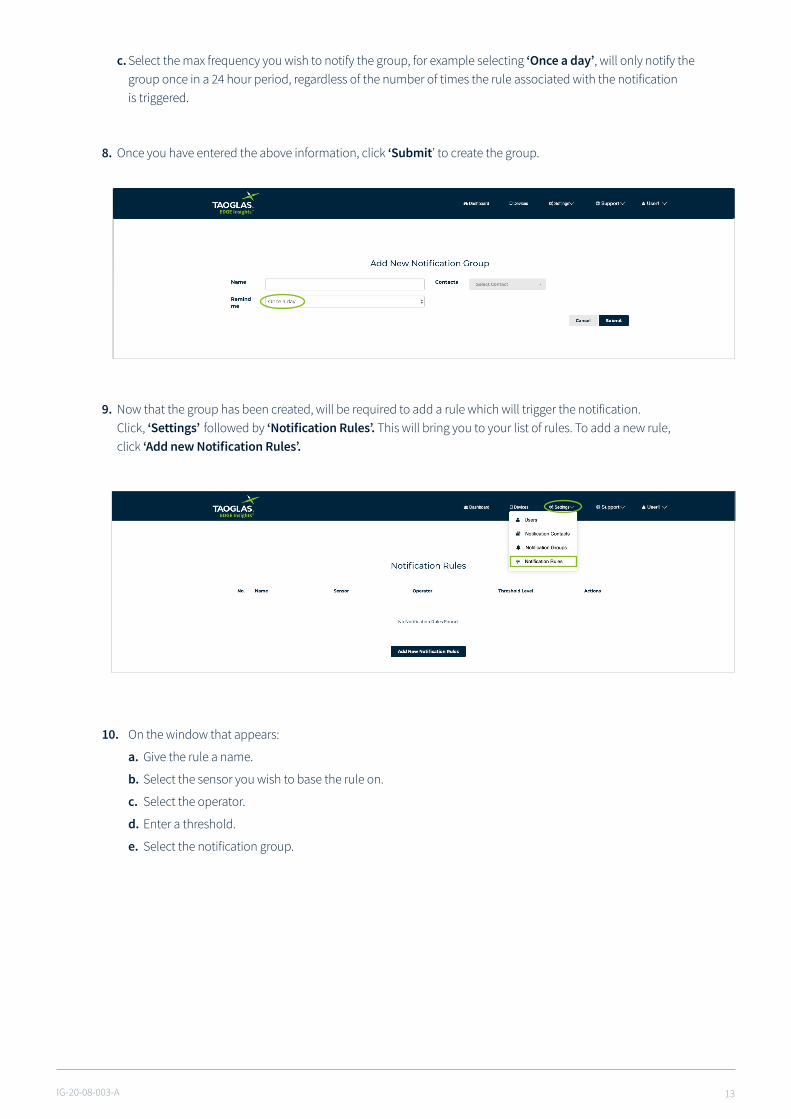
9. Now that the group has been created, will be required to add a rule which will trigger the notification. Click, ‘Settings’ followed by ‘NotificationRules’. This will bring you to your list of rules. To add a new rule, click ‘AddnewNotificationRules’.
10. On the window that appears:
a. Give the rule a name.
b. Select the sensor you wish to base the rule on.
c. Select the operator.
d. Enter a threshold.
e. Select the notification group.
8. Once you have entered the above information, click ‘Submit’ to create the group.
c. Select the max frequency you wish to notify the group, for example selecting ‘Once a day’, will only notify the group once in a 24 hour period, regardless of the number of times the rule associated with the notification is triggered.
IG-20-08-003-A 14
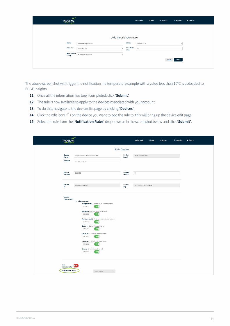
The above screenshot will trigger the notification if a temperature sample with a value less than 10°C is uploaded to EDGE Insights.
11. Once all the information has been completed, click ‘Submit’.
12. The rule is now available to apply to the devices associated with your account.
13. To do this, navigate to the devices list page by clicking ‘Devices’.
14. Click the edit icon( ) on the device you want to add the rule to, this will bring up the device edit page.
15. Select the rule from the ‘NotificationRules’ dropdown as in the screenshot below and click ‘Submit’.

IG-20-08-003-A 15
4.5 Add New Users
1. To add a new user so that they can view the devices you have activated on your account, click ‘Settings’ followed by ‘Users’.
2. The users list page will appear, click ‘Add New User’, which will bring you to a page which allows you to add a new user.
3. On this page enter the users:
a. Email address
b. Username
c. First name
d. Last name
e. Address
4. Click ‘Submit’ to add the user.
5. A new user will be emailed informing them of their new account.

IG-20-08-003-A 16
4.6 Support
1. To access Product Support, click ‘Support’ followed by ‘Product Support’ which will bring you to an online Product support page.
2. To access the User Guide click ‘User Guide’, which will bring you to an online user guide.
IG-20-08-003-A 17
5. Appendix5.1 FAQ
For FAQ’s about the EDGE Connect Set Up please visit taoglas.com/iot-support
For technical support please contact [email protected] Security
The EDGE Connect device security is provided by four mechanisms:
1. Connection to the Cloud-based components via HTTPS, with the servers public certificates held on the EDGE Connect device.
2. Authentication of the device by the EDGE Insights Platform, with the unique and individual private key held securely in a cryptographic coprocessor.
3. Whitelisting of the domains to which the EDGE Connect APN can connect – EDGE Insights and EDGE Insights Platform and NTP servers only.
4. The device periodically reports its configuration hash (security), firmware versions, and certificate bundle version to the EDGE Insights Platform. A report is sent each time a device is powered up, or when the configuration, certificate, or firmware has changed.
5.3 Safety and Regulatory Requirements Warning: Failure to follow instructions could increase risk to safety and noncompliance with regional laws and regulations.
Warning: DO NOT SHORT CIRCUIT, DISASSEMBLE, CRUSH, PENETRATE OR INCINERATE. BATTERY MAY LEAK OR EXPLODE IF HEATED ABOVE 100 °C (212 °F).
Warning: HAZARDOUS AREA WARNING: This instrument has not been designed to be intrinsically safe for use in areas classified as hazardous locations. For your safety, DO NOT use it in hazardous (classified) locations.
Caution: In the case of an emergency, degraded performance will occur if wireless reception is inhibited.
Note: The device has an operating range between -20 and +60 degrees Celsius (-4 to 140 Fahrenheit).
The device can be safely charged in an ambient temperature range of between 0 – 40 degrees Celsius (32-104 degrees Fahrenheit).
The device can be charged with a 5 V/0.5 A power supply and Micro USB Cable.
Note: a) Do not disassemble or open crush, bend or deform, puncture or shred
b) Do not modify or remanufacture, attempt to insert foreign objects into the battery, immerse or expose to water or other liquids, expose to fire, explosion or other hazard.
c) Only use the battery for the system for which it is specified
d) Only use the battery with a charging system that has been qualified with the system per CTIA Certification Requirements for Battery System Compliance to IEEE 1725. Use of an unqualified battery or charger may present a risk of fire, explosion, leakage, or other hazard.
e) Do not short circuit a battery or allow metallic conductive objects to contact battery terminals.
f) Replace the battery only with another battery that has been qualified with the system per this standard, IEEE-Std-1725. Use of an unqualified battery may present a risk of fire, explosion, leakage or other hazard. Only authorized service providers shall replace battery. (If the battery is non-user replaceable).
g) Promptly dispose of used batteries in accordance with local regulations
h) Battery usage by children should be supervised.
i) Avoid dropping the phone or battery. If the phone or battery is dropped, especially on a hard surface, and the user suspects damage, take it to a service center for inspection.
j) Improper battery use may result in a fire, explosion or other hazard.
Caution: Risk of explosion if battery is replaced by an incorrect type. Dispose of used batteries according to the instructions.

IG-20-08-003-A 18
Federal Communication Commission Interference Statement This device complies with part 15 of the FCC Rules. Operation is subject to the following two conditions: (1) This device may not cause harmful interference, and (2) this device must accept any interference received, including interference that may cause undesired operation.
This device has been tested and found to comply with the limits for a Class B digital device, pursuant to Part 15 of the FCC Rules. These limits are designed to provide reasonable protection against harmful interference in a residential installation. This equipment generates, uses, and can radiate radio frequency energy, and, if not installed and used in accordance with the instructions, may cause harmful interference to radio communications. However, there is no guarantee that interference will not occur in a particular installation If this equipment does cause harmful interference to radio or television reception, which can be determined by turning the equipment off and on, the user is encouraged to try to correct the interference by one or more of the following measures:
• Reorient or relocate the receiving antenna. • Increase the separation between the equipment and receiver. • Connect the equipment into an outlet on a circuit different from that to which the receiver is connected. • Consult the dealer or an experienced radio/TV technician for help.
FCC Caution: • Any Changes or modifications not expressly approved by the party responsible for compliance could void the user‘s authority to operate the equipment. • The antenna(s) used for this transmitter must not be co-located or operating in conjunction with any other antenna or transmitter.
RF Exposure Information (SAR) This device meets the government’s requirements for exposure to radio waves. This device is designed and manufactured not to exceed the emission limits for exposure to radio frequency (RF) energy set by the Federal Communications Commission of the U.S. Government.
The exposure standard for wireless device employs a unit of measurement known as the Specific Absorption Rate, or SAR. The SAR limit set by the FCC is 1.6W/kg. *Tests for SAR are conducted using standard operating positions accepted by the FCC with the device transmitting at its highest certified power level in all tested frequency bands. Although the SAR is determined at the highest certified power level, the actual SAR level of the device while operating can be well below the maximum value. This is because the device is designed to operate at multiple power levels so as to use only the poser required to reach the network. In general, the closer you are to a wireless base station antenna, the lower the power output. The highest SAR value for the model device as reported to the FCC when worn on the body, as described in this user guide, is 1.1 W/Kg (Body-worn measurements differ among device models, depending upon available accessories and FCC requirements.)
While there may be differences between the SAR levels of various devices and at various positions, they all meet the government requirement.
The FCC has granted an Equipment Authorization for this model device with all reported SAR levels evaluated as in compliance with the FCC RF exposure guidelines. SAR information on this model device is on file with the FCC and can be found under the Display Grant section of www.fcc.gov/oet/ea/fccid after searching on FCC ID: WYPEU0312.
For body worn operation, this device has been tested and meets the FCC RF exposure guidelines for use with an accessory that contains no metal and be positioned a minimum of 1 cm from the body. Use of other accessories may not ensure compliance with FCC RF exposure guidelines.

All copyrights, trademarks and any other intellectual property rights related are owned by Taoglas Group Holdings Limited.
www.taoglas.com