toward a new generation of photonic humidity sensors
TRANSCRIPT
Sensors 2014, 14, 3986-4013; doi:10.3390/s140303986OPEN ACCESS
sensorsISSN 1424-8220
www.mdpi.com/journal/sensors
Review
Toward a New Generation of Photonic Humidity SensorsStanislav A. Kolpakov *, Neil T. Gordon, Chengbo Mou and Kaiming Zhou
School of Engineering and Applied Science, Aston University, Aston Triangle,Birmingham B4 7ET, UK; E-Mails: [email protected] (N.T.G.);[email protected] (C.M.); [email protected] (K.Z.)
* Author to whom correspondence should be addressed; E-Mail: [email protected];Tel.: +44-121-204-3542; Fax: +44-121-204-3682.
Received: 1 January 2014; in revised form: 29 January 2014 / Accepted: 8 February 2014 /Published: 26 February 2014
Abstract: This review offers new perspectives on the subject and highlights an area in needof further research. It includes an analysis of current scientific literature mainly coveringthe last decade and examines the trends in the development of electronic, acoustic andoptical-fiber humidity sensors over this period. The major findings indicate that a newgeneration of sensor technology based on optical fibers is emerging. The current trendssuggest that electronic humidity sensors could soon be replaced by sensors that are based onphotonic structures. Recent scientific advances are expected to allow dedicated systems toavoid the relatively high price of interrogation modules that is currently a major disadvantageof fiber-based sensors.
Keywords: humidity sensor; relative humidity; adsorption dynamic analysis; acoustic;electronic; optic
1. Introduction
Water is the most essential chemical compound for humans on the Earth. Life, as we know it, isimpossible without water. More than 70% of the surface of our planet is covered by water. Water ispresent everywhere, in air, in soil, in rocks, in plants and an animals. In air or in other gasses water canexist in two different forms. The term moisture refers to water in liquid form that is suspended in air orgas in form of small droplets. The term humidity refers to the concentration of water vapor in air, wherethe water is in a gaseous phase.

Sensors 2014, 14 3987
Humidity is a physical quantity that has significant importance in a number of areas ranging fromlife sciences [1,2] to building automation [3]. Hence humidity control, sensing and monitoring isimportant in a number of areas. Fast humidity sensors are required for the diagnosis of pulmonarydiseases [4] and for mapping the human respiratory system [5] by monitoring the water vapor content ofexhaled breath. For meteorological applications [6] sensing of humidity is important as it indicates thelikelihood of precipitation, dew or fog. In the semiconductor industry, the performance of photo-resistis critically dependent on the humidity. In the electronics industry, humidity monitoring is important aselectronic items may malfunction due to high humidity. Furthermore, humidity control is essential insome buildings where humidity sensitive materials are stored such as museums, archives, warehouses.For human comfort and to maintain the quality of a number of food products, it is important to controlhumidity levels inside buildings, cars, shops and other places. Many different types of humidity sensorsare needed to cover all the previously mentioned applications. As a consequence, a wide range of sensortypes (see Figure 1) has been proposed for humidity measurements.
In Figure 1, humidity sensors have been organized into three groups. Electronic sensors are the mostcommon type of sensors today. This technology has a very long history and follows the first generation ofmechanical humidity sensors. These mechanical sensors were based mainly on change in the mechanicalproperties of some materials. These materials were frequently of animal origin, for example, horse orhuman hairs. These first mechanical sensors, which were slow and imprecise, were used throughouthuman history until the second half of twentieth century. At that time, practically simultaneously with thefirst electronic chips, the second generation of the humidity sensors has emerged. These were electronichumidity sensors. Today, humidity sensing based on electronic sensors is the dominant technology.
Figure 1. Types of humidity sensors.
More recently, research has been carried out on the use of acoustic waves to measure humidity. So far,this research has not led to the development of new sensors and little research is currently being reportedin this area in comparison with other humidity sensing areas. However, a third generation of sensors

Sensors 2014, 14 3988
has now emerged with the development of fiber technologies. These sensors, which are mainly basedon interferometric techniques, are faster and more robust than the electronic ones. This technology,which has been developed over the past twenty years, is now making its first attempts to compete withthe well-established electronic one. Today, humidity sensors based on fiber interferometers still have arelatively high cost in comparison with electronic ones. However the fiber sensors have some importantadvantages. These sensors do not generate electrical sparks because the optical humidity sensors do notuse electricity in the sensor head. This allows the use of optical humidity sensors in chemical industry,where flammable solvents are frequently employed.
A comparison between response time of different types of humidity sensors is illustrated in Figure 2.The acoustic sensors (red color) are slowest group. The second group (green color) are experimental andcommercially available electronic sensors. Finally, the blue color illustrates the performance of opticalhumidity sensors. The fastest sensors, which are depicted on the left side of Figure 2, are interferometricsensors and have a response time of less than one second. These sensors are based on photonic crystalfibers and use poly-vinyl-alcohol as the hydrophilic material.
Figure 2. Response times of different types of humidity sensors.
Current research draws attention to the fact that important technological advances have beenmade during the last ten years in all competing branches of humidity sensing technologies. A newgeneration of nano-technology based humidity sensors, complimentary metal oxide semiconductormicro-electro-mechanical system (CMOS-MEMS) humidity sensors have been investigated anddemonstrated [7]. These sensors have an extremely fast response time in comparison with the electronicsensors that prevail in the market. The main advantages of these devices are their simplicity and theavailability of low cost interrogation modules. However, the sensitive head of these sensors is expensiveto produce in small quantities. Another kind of optical humidity sensor, which is based on nano-capillary
Sensors 2014, 14 3989
interferometer [8–11] has been widely investigated in scientific literature. This sensor has a very simpleand cheap sensing element. The manufacturing of these elements does not require a large investment inmachinery, allowing on demand production. One purpose of this article is to examine the most currentresearch in the area of humidity sensing. This review offers new perspectives and highlights an area inneed of further research. Moreover, the report includes a review of recent scientific literature mainlycovering the last ten years. The second section of the article is devoted to a review of the latest advancesin the field of electronic humidity sensing. Progress in the field of acoustic humidity sensing is examinedin the next section. Finally, in the forth section, the state-of-art in optical humidity sensing is described.The major findings indicate that a new generation of humidity sensing technology based on optical fibersis emerging.
2. Electronic Humidity Sensors
This section discusses the main characteristics of state-of-the-art electronic sensors for humiditydetection and recent research in this area. Today these sensors are the dominant technology on theworld-wide market. They detect humidity by measuring changes in the electrical characteristics of ahumidity-sensitive thin film. The relatively simple design and low price of the interrogation moduleare the two main advantages of electronic sensors. On the other side of the coin their disadvantagesare: the need for regular calibration; the difficulty in measuring relative humidity below 5% level;poor linearity and relatively long response time, which typically is of several tenth of seconds or evenminutes. Moreover, the use of electronic humidity sensors in certain critical environments, remote places,potentially explosive atmospheres and areas with high electromagnetic interference is either difficult orsome times impossible.
Research over the past ten years has been largely aimed at improving these characteristics and thiswill be discussed in the remainder of this section. In the electronic sensors, water vapor is absorbedinto some hydrophilic layer and this changes the impedance of the device. Contacts are applied tothe layer to measure this change. Commercially available humidity sensors are briefly reviewed in thefirst subsection. In the following subsections, the detectors will be classified by whether changes aremeasured in the capacitance or the resistance of the sensor. The second subsection is dedicated to adescription of the experimental advances in the field of capacitative humidity sensors. Finally, humiditysensors that are based on resistivity changes are illustrated in the last subsection.
2.1. Commercially Available Humidity Sensors
Electronic humidity sensors, which are typically available for less than $10, are the most commonlyavailable low cost sensors today. Despite the low cost, these devices are quite sophisticated. Most ofthese sensors can be connected directly to a microprocessor without requiring an external amplifieror digitizer. The integration of a temperature sensor allows the measured data to be corrected fortemperature variations. In addition, an external microprocessor can calculate both the dew point andthe concentration of water vapor. However, these commercial devices fall short of requirements in someareas as is listed below:

Sensors 2014, 14 3990
• too long response time in some applications
• a poor accuracy, which is close to ±2%, especially at low and high humidity
• wide hysteresis and poor linearity
• insufficient temperature operational range and bad long term stability.
The response time of these sensors is typically in the range 5–60 s. Although this is adequate formany applications, it is too long in some other areas such as for a breathing sensor. The accuracy islimited to a few percent RH and is worse in the extreme ranges of 0%–10% RH and 90%–100% RH.The devices have hysteresis, in other words the detector output for a given humidity depends on whetherthe humidity is increasing or decreasing. The maximum width of this hysteresis is typically a fewpercent RH. The maximum operating temperature is in the range 80–120 ◦C which is not high enoughfor some industrial drying applications. Finally, if the temperature of a humidity sensor drops below thedew point, condensation will prevent it operating until the temperature of the sensor has been increasedfor long enough for the water to evaporate. This is a common problem with humidity sensors. Someexamples of performance of commercially available sensors are summarized in Table 1.
Table 1. Performance of commercial electronic humidity sensors.
Sensor Type Response, s Range, %RH Hysteresis, %
Inc Dec min max
SHT15 Polymer C 8 8 0 100 2DHT22 C NA NA 0 100 2HR202 R 10 10 20 95 1DHT11 R 10 10 20 90 4
HMT330 1 Electronic 8 17 0 100 1HMT330 2 Electronic 20 50 0 100 1HMT330 3 Electronic 40 60 0 100 1
HC2-C Electronic 15 NA 0 100 NAFluke 971 Electronic 60 NA 5 95 NA
1 With grid filter; 2 With steel netting filter; 3 With sintered filter.
2.2. Capacitive Humidity Sensors
Capacitive sensors are typically produced by depositing a thin layer of a sensitive material on toclosely spaced electrodes. Sometimes, these electrodes take the form of two interdigitated combstructures to increase the capacitance. This allows water vapor to interact with the top surface of thesensitive layer. Moreover, the interdigitated electrodes are simpler to produce using photolithographythan a structure with electrodes on both sides. Capacitive sensors have the advantages of low powerrequirements and a high output signal. Clearly, the performance of a capacitive sensor will dependcritically on the sensitive layer used. Table 2 lists the properties of capacitance sensors using differentsensitive layers.

Sensors 2014, 14 3991
The trend to minimize the size of electronic devices reveals itself in the research and design of newhumidity sensors [12,13]. Recently a new generation of electronic sensors based on CMOS-MEMS [7],nano-technology [14–18] and capacitive [19] technology has been reported in the scientific literature.These new sensors are based on nano-structured TiO2 thin films and have a reaction time which isapproximately ten times shorter [19] than the devices that are widely used today. Figure 3 shows anano-structured thin TiO2 film that was deposited using glancing angle deposition (GLAD).
Table 2. Performance of capacitative humidity sensors.
Sensor Type Response, s Range, %RH Hysteresis, % Ref.
Inc Dec min max
Composite (PEPC + NiPc + Cu2O) C 13 15 40 100 13 [20]Graphene oxide film C 10.5 41 15 95 5 [21]
MWCNTs C 45 15 11 97 NA [22]Polyimide film C 1 1 30 90 2 [23]
3 µm polyimide film on parylene on silicon C 1 1 30 90 2 [24]Polyimide film C 1.7 2.3 30 100 NA [25]Polyimide film C NA NA 50 90 NA [26]
Standard CMOS polymer film C 70 70 10 95 5.5 [27]Standard CMOS polymer film C 70 70 10 95 3.1 [28]
Polypyrrole C NA NA 25 95 small [29]Mesoporous silica C NA NA 0 50 NA [30]
Capacitive-dependent crystal C 0.1 0.1 20 98 0.3 [12,13]
Figure 3. Cross-sectional SEM images of the thin TiO2 films deposited at differentflux angles. (a) α = 60◦; (b) α = 70◦; (c) α = 75◦; (d) α = 80◦, reproduced from [31]with permission.

Sensors 2014, 14 3992
Porous inorganic materials, such as porous silicon, have been investigated however organic materialshave the potential for significantly lower cost. These can be prepared by low cost techniquessuch as spin coating, drop casting, dip coating or spray coating. Nickel phthalocynine (NiPc) andpoly-N-epoxy-propyl-carbazole (PEPC) have been found to be sensitive to humidity. Ahmad et al. [20]have investigated the performance of mixtures of these compounds with copper oxide. The addition ofcopper oxide will increase the surface roughness to produce a larger surface area and has the potentialto produce a greater sensitivity and reduced response time. Using this technique three times greatersensitivity was obtained however this material was only suitable for an operating range above 40% RH.
Graphene oxide is an interesting material for achieving a high sensitivity and fast response time dueto its single layer nature and hydrophilic surface. Bi et al. [21] have investigated the use of these filmsas a humidity sensor. They improved the sensitivity by a factor of ten compared with conventionalcapacitance sensors and their sensor had a reasonable response time of 10.5 s for increasing humidityalthough this increased to 41 s for reducing humidity. The variation of the impedance of these structureswith frequency was complicated and the devices only operated over a range of 15%–95% RH.
Multi-wall carbon nano-tubes (MWCNTs) [22] where the tube diameter varies are of interestfor improving the performance of humidity sensors at low humidity due to capillary condensation.This is an effect where condensation can occur in thin capillaries at significantly below the saturationvapor concentration. The radius r required for condensation at a vapor pressure p is given by theKelvin equation:
r = −2γVLcos(Θ)
RTln( pp0
)(1)
where γ is the surface tension, VL is the molar volume, Θ is the contact angle, R is the gas constant,T is the temperature, p0 is the saturation vapor pressure and p
p0is the relative humidity. The Kelvin
radius r typically has a value of a few nanometers and increases as the RH increases. This allows morenanotubes to become filled with water. A sensor based on this principle was proposed by Chen et al. [22].The sensor has improved sensitivity at low levels of humidity in comparison with a standard sensorwithout MWCNTs.
The relatively slow response of standard humidity sensors is a disadvantage in applications involvingtransient humidity changes such as in industrial process control and for monitoring atmospherichumidity. Kang and Wise [23] have developed a faster sensor based on polyimide that has a responsetime of around 1 s. Their design was based on an analysis of the diffusion into the sensor material. Byetching the sensitive material into an array of pillars, they find that the increased surface area reduces thediffusion time by a factor of ten. By using pillars with diameters of 15, 10 and 5 µm the response time wasreduced to 6.9, 1.9 and 1.0 s respectively. A second feature of their design was to include an integratedpoly-silicon heater and temperature sensor. This was used to prevent the temperature dropping belowthe dew point to maintain a short time of response and also to measure high humidity without having thesensor exposed to it. Using the heater, the relative humidity was calculated using the formula [23]:
RHT=T1=p0(T2)
p0(T1)RHT=T2 (2)
where T1 and T1 are the temperatures before and after heating and p0(T ) is the saturation pressure at atemperature T .
Sensors 2014, 14 3993
For a low-cost device, there is considerable advantage if the sensor material is compatible withsilicon processing. Thin organic films fall into this category and several papers have described sensorscompatible with MEMS [25,26] or CMOS [27,28] technology. The CMOS used top level metal and astandard passivation layer as the sensor. A self-calibration circuit was added to simplify the operation.MEMS technology allows multiple sensors (for temperature, humidity, pressure, wind speed and winddirection) to be integrated on a single chip.
2.3. Resistive Humidity Sensors
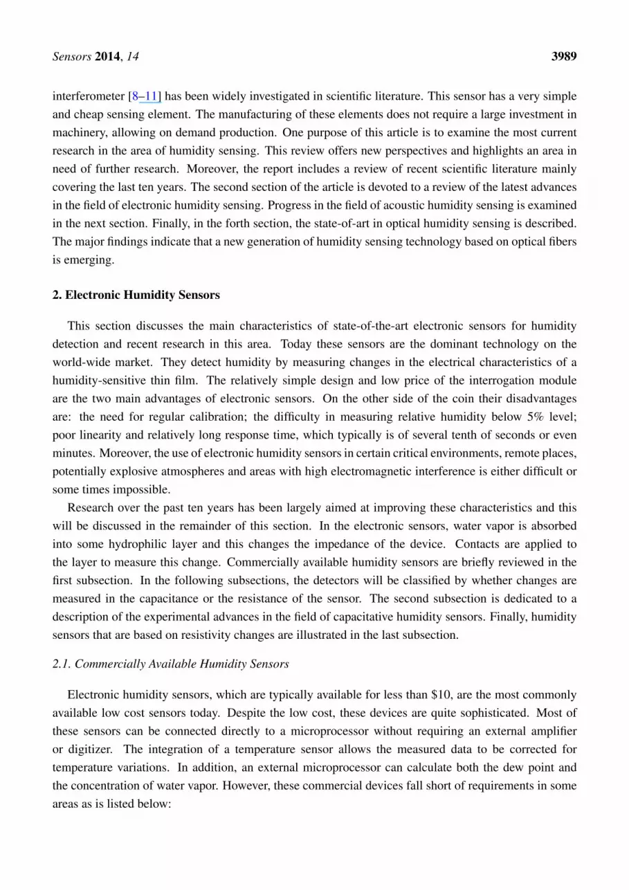
As with capacitive sensors, recent research on resistive sensors has been aimed at improving theirsensitivity, response time, linearity and hysteresis characteristics.The characteristics of some recentlyreported resistive humidity sensors are listed in Table 3. Arshaka et al. have investigated the use ofthermally deposited In2O3 [32] and sintered pastes of MnZn ferrite [33] and achieved low hysteresis andgood linearity.
Kuang et al. [34] have investigated the properties of a single SnO2 nano-wire as a resistive humiditysensor. The use of a single nano-wire will lead to a very small sensor and may lead to a faster responsetime. The growth process resulted in a high concentration of oxygen vacancies leading to the surface ofthe nano-wire being very sensitive to oxygen and water vapor in the air. Characterization of this deviceshowed a reproducible linear response with response and recovery times in the range 120–170 s and20–60 s respectively. Lee [35] has researched the properties of nano-structured carbon nitride CNx filmsdeposited by radio-frequency (RF) sputtering. The CNx bonds are expected to react reversibly withhydrogen and hydroxyl groups to generate a hydrophilic surface which can absorb and release watermolecules. The resulting layers were found to have a reasonably linear response with a hysteresis whichdepended strongly on the substrate used. This was due to the formation of ink bottle shaped defectswhich trap water in the interior.
Table 3. Performance of resistive humidity sensors.
Sensor Type Response, s Range, %RH Hysteresis, % Ref.
Inc Dec min max
In2O3/SiO R NA NA 40 90 NA [32]MnZn Ferrite R 17 25 30 90 0.97 [33]
Fe-Al-polyaniline on CMOS R NA NA 32 55 NA [36]SnO2 nanowire R 120–170 20–60 5 85 NA [34]
CNx deposited by RF sputtering R 150 175 5 95 3 [35]Sulfonated Polycarbonate R NA NA 11 90 4 [37]
Polyaniline/PVA R NA NA 25 85 NA [38]MWCNT/polyimide composite film R NA NA 10 95 NA [17]
Polyimide films have been successfully used as capacitive humidity sensors however they have alsobeen considered for use as resistive humidity sensors. Although the resistance of these devices is verysensitive to humidity, with the resistance changing by many orders of magnitude, they are not ideal

Sensors 2014, 14 3994
humidity sensors due to their variability (requiring calibration), highly non-linear response and poorresponse at low humidity. Yoo et al. [17] have investigated a sensor that was manufactured by addingplasma-treated MWCNs to the polyimide film to improve its performance. As the doping level wasincreased, the resistance of the films remained very high until the density exceeded the percolationthreshold of 0.05% where the resistance dropped rapidly. At sufficiently high concentrations, theresistance is governed by transport of electrons through the continuous paths, which the nano-tubesform. Increasing the humidity is found to increase the resistance due to a combination of chargetransfer between the MWCNs and the water molecules, which reduces the mobile carrier concentrationin MWCNs, and increased pressure due to swelling of the polyimide. For a nano-tube concentration of0.4%, this leads to a highly linear variation of resistance with humidity.
The extremely small size of these sensors drastically improves characteristics. The typical design ofp-MWCNT/PI composite sensor is shown on Figure 4. Standard silicon micromachining was used toproduce a thin film suspended over a silicon substrate. One major advantage of these sensors is theirhigh linearity over the entire operational range. These sensors exhibit a sensitivity of 0.0047% RH.
Figure 4. (a) Scanning electron microscope (SEM) image of active layer; and (b) schematicview of the resistive-type RH sensors based on p-MWCNT-PI composite film, reproducedfrom [17] with permission.
3. Acoustic Humidity Sensors
In this section humidity sensors based on acoustic wave technology are reviewed. Acoustic methodsof humidity measurements can be classified as mechanical methods. This measurement technique isbased on the variation of mechanical properties of a hydrophilic material when water molecules areabsorbed on to it. Existing methods of humidity measurement are based on surface acoustic waves(SAW), the change in the resonance frequency of a quartz crystal microbalance (QCM), quartz tuningforks (QTF) and on bulk acoustic waves (BAW) technology. The change in frequency of the acousticresonance is typically used for detecting the change of material density that occurs because of absorptionof water vapor from the surrounding atmosphere [39,40]. The change of density of the hydrophilicmaterial changes the resonance frequency. This frequency shift has been theoretically analyzed by

Sensors 2014, 14 3995
Sauerbrey [41]. The Sauerbrey equation gives the frequency shift of a quartz oscillator due to absorptionof a small mass ∆m of water:
∆f = − 2f 2
A√µρ
∆m (3)
where f is resonant frequency of the circuit, ∆f is the frequency change, ∆m is change of mass due tovapor absorption, A is the area of active crystal, ρ is quartz density (ρ = 2.648 g/cm3) and µ is Shearmodulus of quartz for AT-cut crystal (µ = 2.947 × 10¹¹ g/cm·s2).
This section is organized as follows: in the first subsection we provide a review of most relevantachievements in the branch of SAW sensors, the second subsection describes the state-of-art in the sectorof quartz crystal microbalance humidity sensors. Although, there are not many publications devoted toinvestigating of BAW and QTF humidity sensors we have included a short description of advances inthis area in the third subsection. Moreover, we have gathered together the most relevant characteristicsof all these types of acoustic sensors in Tables 4 and 5.
Table 4. Performance of acoustic humidity sensors.
Sensor f Sensitivity Response PH (%) Ref.
(MHz) (ppm 7/%RH) Time (s) min max
MWCNT/Nafion nanofiber film 1 ∼500 885.2 10 10 80 [42]APTS-P 1 [43] 433 15 10 10 100 [44]
PVA-coated dual resonator 1 ∼468 11–395 1,800 20 80 [45]Cellulose acetate film 1 302 3.31 NA 10 80 [46]
Nafion layer 1 ∼302 2.75 ≤20 10 100 [47,48]NPF-LSAW 1 60–110 0–6 6 0.25 10 90 [49]
Monodisperse mesoporous silica 1 10 250–720 10 10 100 [50]Nanocrystalline Zn oxide 2 0.032 1.1597 ≤150 10 100 [51]Fluorinated polyimides 3 5 2 300 15 85 [52]
Nano-tubes/Nafion composite 3 9 0.1123 5 100 23.4 5 3,030.5 4 [53]Polypyrrole AgTiO2 nano-part. 3 10 0.0246 5 12 0 5 10,000 5 [54]
Nanofibrous membrane 3 5 0.1–10 80–150 20 95 [55]ZnO nano-tetrapods 3 10 0–3.3 NA 30 90 [56]
Carbon nano-tube film 3 25 ≤4 60/70 8 5 97 [57]ZnO nanostructure film 3 25 0.26 90/120 8 5 97 [58]
Nanostructured ZnO 3 10 ≤1 NA 20 90 [59]ZnO on silicon base 4 35/86 400/16 ≤25 20 92 [60]
ZnO-FBAR 4 1,430 1.4 NA 25 85 [61]
1 SAW configuration; 2 Quartz tuning fork; 3 Quartz crystal microbalance humidity sensors; 4 Bulk humiditysensors; 5 In Hz/ppmv; 6 dB/PH(%); 7 Parts per million; 8 Response/recovery time.

Sensors 2014, 14 3996
Table 5. Linearity and hysteresis of acoustic humidity sensors.
Sensor Linearity Hysteresis 5 Ref.
MWCNT/Nafion nanofiber film 1 Linear between 10% and 75% ≤10% [42]APTS-P 1 [43] Linear NA [44]
PVA-coated dual resonator SAW 1 Non linear NA [45]Cellulose acetate film 1 Linear between 10% and 60% ≤7% [46]
Nafion layer 1 Linear between 10% and 60% ≤12% [47,48]NPF-LSAW 1 Non linear NA [49]
Monodisperse mesoporous silica 1 Linear between 0% and 80% ≤5 [50]Nanocrystalline Zn oxide 2 Linear between 40% and 100% NA [51]Fluorinated polyimides 3 Non linear NA [52]
Carbon nano-tubes/Nafion composite 3 Linear NA [53]Polypyrrole AgTiO2 nano-particles 3 Linear NA [54]
Nanofibrous membrane 3 Exponential between 20% and 95% NA [55]ZnO nano-tetrapods 3 Non linear NA [56]
Carbon nano-tube film 3 Linear NA [57]ZnO nanostructure film 3 Linear NA [58]
Nanostructured ZnO 3 Non linear NA [59]ZnO on silicon base 4 Non linear NA [60]
ZnO-FBAR 4 Non linear NA [61]
1 SAW configuration; 2 Quartz tuning fork; 3 Quartz crystal microbalance humidity sensors; 4 Bulk humiditysensors; 5 The width of hysteresis in relation to whole measured interval.
3.1. Surface Acoustic Waves Humidity Sensors
Generally, SAW sensors are based either on organic molecules or on polymers whose interactions withthe absorbed water molecules leads to a change in the velocity of surface waves. During the last decadeexperimental efforts have been focused on improving the surface quality and testing new hydrophilicmaterials. Various techniques such as drop coating [62], the Langmuir-Blodgett technique [63], spincoating [64], coating using the method of fast expansion of a supercritical solution (RESS) [65],electro-sprayed silicon-containing polyelectrolyte [66] and air-brush coating [67] have been consideredfor the deposition of the active material. For the electro-spray coating process, Li [44] has examinedthe influence of the polymer deposition rate and polymer solution concentration on the properties of thehumidity sensor.
The effect of droplet diameter on intrinsic acoustic losses in the sensor have been investigated bySarcar and co-workers [68]. Sarkar compared the coating film quality and performance of the sensorthat was coated using the AC electro-spray technique with similar ones that were coated using the DCelectro-spray technique, the air-brush and RESS. They concluded that much lower acoustic losses wereobtained using the DC electro-spray process due to the rapid evaporation of the nano-droplets.
Very fast SAW sensors based either on thin films of poly-vinyl-alcohol (PVA) or on thinfilms of poly-vinyl-pyrrolidone (PVP) have been described by Buvailo [69]. These sensors showresponse/recovery times 1.5/2.5 s respectively in the humidity interval of 5%–95%.

Sensors 2014, 14 3997
3.2. Quartz Crystal Microbalance Humidity Sensors
These sensors tend to be quite slow in comparison with SAW sensors, with a response time ofhundreds of seconds and quite non-linear behavior. However, some interesting findings have recentlybeen published.
A hybrid sensor has been demonstrated by Shinbo [52]. This sensor was fabricated by depositingeither slab or ridge optical waveguides made of fluorinated polyimides on the quartz crystalmicrobalance. Accurate discrimination of adsorbed chemical species has been successfully performedby observing the change in the mass load and either the optical transmittance or optical spectrum.
Su and co-workers [53] have compared the behavior of a sensor using composite of nafion withsingle-wall carbon nano-tubes (SWCNTs) with a sensor using multi-wall embedded carbon nano-tubes.This sensor showed quasi-linear behavior and a recovery time close to 100 s. Novel low-humidity sensorswere fabricated in situ using photo-polymerization of polypyrrole nano-particles [54]. These sensorsshowed good sensitivity at low humidity and an unusually short response time. The authors associatedthis phenomenon with high local electrostatic charge of TiO2 nano-particles, which caused dissociationof water molecules.
In [55] it was shown that the sensitivity of fibrous composite polyacrylic acid (PAA)/polyvinyl-alcoholmembranes was two times higher than the sensitivity of a corresponding flat film at 95% RH. Themembranes based on fibrous composite have the highest sensitivity because of their extremely highsurface area.
The use of zinc oxide has been investigated in [56,58,59]. These experiments have confirmed thewell known fact [50] that the thickness of the sensitive film needs to be optimized in order to achievethe best possible performance. In addition, it was concluded that the structure of the zinc oxide filmwas important for sensor performance. Films structured in the form of either nano-rods or nano-wiresshowed slightly better performance than films structured in form of nano-tetrapods.
Finally, the hydrophilic potential of MWCNT [57] was investigated using measurements with QCM.The sensor, operating in the range between 5% and 95% of RH, has the response/recovery times of60 and 70 s respectively and exhibits linear behavior.
3.3. Bulk Acoustic Waves and Quartz Tuning Forks Humidity Sensors
The resonant frequency of these devices strongly depends on temperature and research aimed atreducing the sensor temperature dependence is presented in [60]. This sensor takes advantage ofthe coexistence of fundamental and higher order resonance modes in the interval 30–100 MHz. Thetemperature dependence of the sensor has been successfully compensated in the range from 20% to 92%RH over the temperature range from 25 to 70 ◦C.
Zhou et al. [51] have presented the application of QTF coated with nano-crystalline ZnO film as arelative humidity sensor. Moreover, the interferences, which can be induced by either ethanol or acetonevapors have been discussed. The results shown that the uniformity of the ZnO film is important for theperformance of the sensor.
Sensors 2014, 14 3998
4. Optical Humidity Sensors
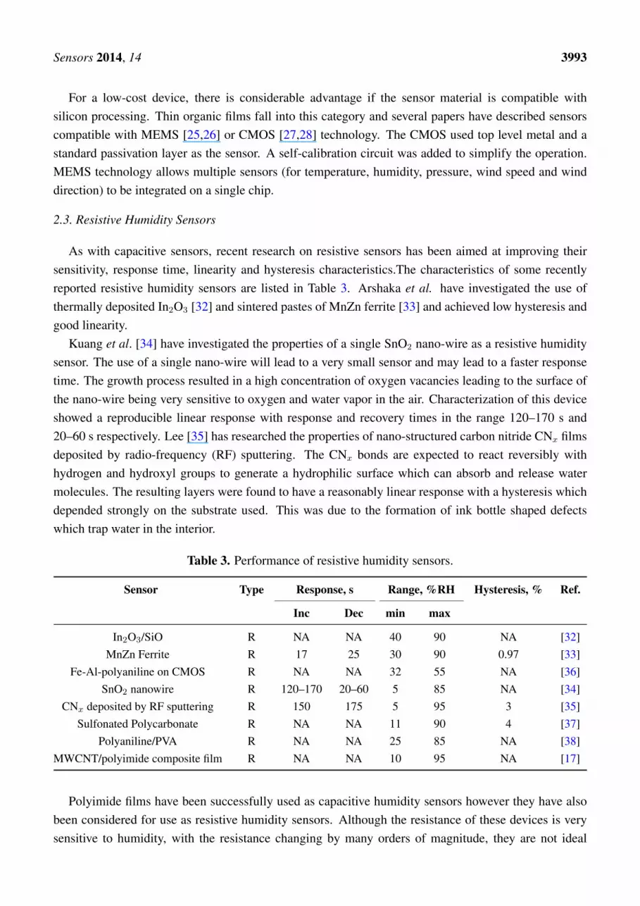
The intensive investigation of the potential of optical fiber sensors began in the middle of the1980s, after the first optical fibers became commercially available. At that time, the technology forelectronic sensing was already well established. However, from the beginning, optical sensors havebeen successfully employed for a range of specific applications which electronic sensors are unable toperform. These include electromagnetic compatibility, multi-point measurements and the possibility ofremote interrogation. Additional advantages of fibre sensors include miniature size and small weight. Allthese features make optical fibre sensors suitable for applications where electronic or acoustic ones areeither not recommended or inappropriate. For example, fibre sensors offer a solution for monitoringparameters such as temperature and humidity inside microwave ovens. Optics sensors do not useelectricity and consequently they can be used for monitoring of inflammable liquids or gases becauseof the absence of sparks. Fibre sensors are also a viable alternative in harsh environments such as thosewith corrosive substances [70]. Some of these sensors are also chemically inert, which allow their use inchemical reactors. Moreover, these sensors have been successfully used for monitoring historical objectsin remote places [71]. For these reasons the acceptance of fibre sensors in several industrial sectors isgrowing steadily. Characteristics of some optical humidity sensors, which are commercially availabletoday are summarized in in Table 6.
Table 6. Performance of commercial optic humidity sensors.
Sensor Accuracy Response, s Range, %RH
min max
Nanosonic Inc. 6% at 20 ◦C 0.1 0 100O-eland FBG-based 4.5% fast 10 100
The research on optical humidity sensors started about 25 years ago. During the last 20 years theprices of fiber components have fallen and the quality of these components has been improved. Theavailable range of fiber based sensors has significantly increased and can replace traditional sensors inmany applications such as gyroscopes, tension and bending sensors, stress sensors, humidity and waterlevel sensors.
For humidity sensing, a range of different techniques and approaches have been proposed includingspectroscopy, change of reflectance of surfaces [72], evanescent wave interactions [73], Bragg and longperiod gratings [74–78], interferometers [79], carbon nano-tubes [14] and more recently, photonic crystalfibres [8,80]. Most fibre optic humidity sensors require a hygroscopic material, which is typicallydeposited on a section or on the tip of the optical fibre [81]. Humidity changes the optical propertiesof the material, which in turn, modifies a feature of the guided light giving rise to a detectable signal.Bedoya [82] has discussed an interesting fiber-optic humidity sensor based on the optical properties ofindicator dyes.
In this section we will summarize the technological advancements that have recently emerged in thebranch of sensors based on optical fiber technology. In the first subsection the latest achievements inthe interferometric humidity sensing are reviewed. The second subsection is dedicated to the humidity

Sensors 2014, 14 3999
sensors that are based on long period gratings. Advances in hybrid relative humidity sensors areillustrated in the third section. Finally, in the fourth and the fifth subsections the progress in humiditysensing based on evanescent-waves interactions and some other exotic humidity sensors are described.The main features of some optical fibre-based humidity sensors are summarized in Tables 7 and 8.
Table 7. Performance of optic humidity sensors.
Sensor Sensitivity Response, s Range PH (%) Ref.
Inc Dec min max
ZnO nanoparticles in solgel 1 0.0103 dB/%RH 0.86 0.54 5 95 [83]SiO2 Nanoparticles 1 0.3 dB/%RH 0.15 0.1 40 98 [84]Silica xerogel film 1 7.9× 10⁻² nm−1 ·%−1 10 120 4 100 [85]Hollow core fiber 1 3.02 mV/1%RH 60 NA 0 90 [86]
Surface Plasmon Resonance 1 0.943 nm per RH% <0.5 NA 5 95 [87]CoCl2 into a PVA composite 1 0.5 dB/%RH 120 NA 25 65 [88]
Di-ureasil coated FBG 2 22.2 pm/%RH 600 NA 15 95 [77]Bent single mode optical fiber 2 <0.1 dB/%RH 0.05 NA 25 90 [89]
Gelatin film 2 <0.1 dB/%RH 0.07 NA 9 94 [90]Polyimide-coated FBG 3 −0.000266 V/%RH 5 NA 11 98 [75]
PVA coated FBG 3 1.994 µW/%RH 2 NA 30 95 [91]Tilted FBG with PVA 3 14.947 dBm/%RH 2 NA 20 98 [92]Polyimide coated FBG 3 5.6 pm/%RH 2,700 NA 20 98 [93]
PVA 4 0.60 nm/%RH 3× 10⁻⁴ 5× 10⁻⁴ 30 90 [94]FBG in a polymer fibre 35.2 pm/%RH 1,800 NA 50 95 [95]
Luminescent Ru(II) complex NA <90 NA 4 100 [82]SiO2 nanospheres 5 0.2 nm/%RH <0.02 NA 20 80 [96]
1 Absorption measurements; 2 Evanescent wave; 3 Strain; 4 Interferometric; 5 LPFG.
4.1. Interferometric Humidity Sensors
Interferometric techniques are the most exact and fastest of all the existing optical methods ofmeasurement. Interferometric relative humidity sensing has been successfully tested in medicine [97]to monitor human breathing. This application in particular is useful for the diagnosis and study of theprogression for such serious diseases as the sleep apnea syndrome. The most significant characteristicsof humidity sensors based on interferometric measurements are their relative simplicity, extremelyhigh sensitivity and short time of response. The main advantage of interferometric humidity sensingis the absence of hydrophilic material that can be easily damaged when the sensor works in a harshenvironments [70]. The main disadvantage of these sensors is their low selectivity. This sort of sensorsmeasures the changes in the refractive index of the atmosphere next to the fibre, consequently they aresensitive to a variety of contaminants. For this reason the interferometric techniques have sometimesbeen complemented by the use of hydrophilic materials. Numerous research groups have investigateddiverse sensor architectures to improve sensor sensitivity and robustness.

Sensors 2014, 14 4000
Table 8. Linearity and hysteresis of optic humidity sensors.
Sensor Linearity Hysteresis 6 Ref.
ZnO nanoparticles in solgel 1 Linear NA [83]SiO2 Nanoparticles 1 Linear 40%–98% 0.25% [84]Silica xerogel film 1 Linear 0%–60% NA [85]Hollow core fiber 1 Linear NA [86]
Surface Plasmon Resonance 1 Linear NA [87]CoCl2 into a PVA composite 1 Non linear <3% [88]
Di-ureasil coated FBG 2 Non linear NA [77]Bent single mode optical fiber 2 Linear 25%–90% NA [89]
Gelatin film 2 Non linear NA [90]Polyimide-coated FBG 3 Linear NA [75]
PVA coated FBG 3 Non linear <4% [91]Tilted FBG with PVA 3 Linear 20%–80% <10% [92]Polyimide coated FBG 3 Linear <5% [93]
PVA 4 Non linear 15% [94]FBG in a polymer fibre Linear NA [95]
Luminescent Ru(II) complex Non linear 4% [82]SiO2 nanospheres 5 Non linear NA [96]
1 Absorption measurements; 2 Evanescent wave; 3 Strain; 4 Interferometric; 5 long period fiber gratings (LPFG);6 The width of hysteresis in relation to whole measured interval.
The sensor based on the fiber Sagnac interferometer was developed by Chen [98]. The hydrophilicmaterial called chitosan has been used in this sensor. Chitosan swells when the humidity is increased.This was used to produce strain and changes the polarization properties of the fiber. This sensor wascompared with the sensor implemented in Fabry-Perot geometry using the same material [81]. Thesensor based on Fabry-Perot geometry showed an extremely short response time of 380 ms.
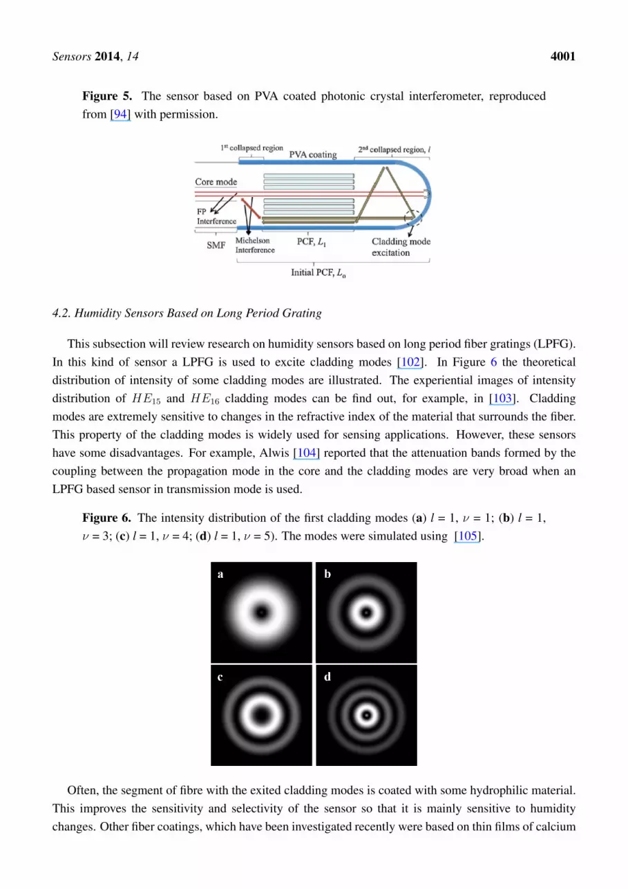
A miniature optical RH sensor based on a polymer infiltrated photonic crystal fiber was reportedby Mathew [99]. Experiments showed that the sensitivity of a sensor based on photonic crystal fibercan be improved [100] by infiltrating the voids of the photonic crystal with a hydroscopic polymer.At a later date, Wong [94] combined PVA, which is considered to be a very promising material forhumidity sensing, with the interferometric technique proposed by Mathew [100]. The sensor is illustratedin Figure 5. The sensor with a 9% (w/w) coating achieved a sensitivity of 0.60 nm/% RH, exhibitedlittle hysteresis, high repeatability, low cross-sensitivity to temperature and ammonia gas and stableperformance during a seven day testing period. Moreover, the sensor showed short rise/fall times of300/500 ms respectively.
Finally, Liang [101] investigated the combination of a PVA coating and loop mirror based onpolarization maintaining fiber. His experiments showed quite a narrow range of sensitivity between20% and 85% RH.
Sensors 2014, 14 4001
Figure 5. The sensor based on PVA coated photonic crystal interferometer, reproducedfrom [94] with permission.
4.2. Humidity Sensors Based on Long Period Grating
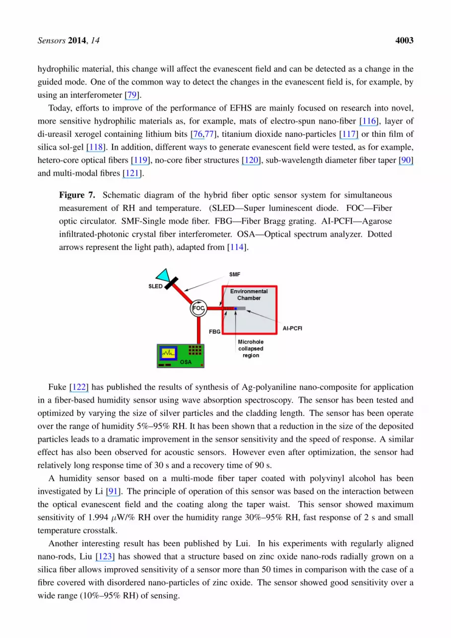
This subsection will review research on humidity sensors based on long period fiber gratings (LPFG).In this kind of sensor a LPFG is used to excite cladding modes [102]. In Figure 6 the theoreticaldistribution of intensity of some cladding modes are illustrated. The experiential images of intensitydistribution of HE15 and HE16 cladding modes can be find out, for example, in [103]. Claddingmodes are extremely sensitive to changes in the refractive index of the material that surrounds the fiber.This property of the cladding modes is widely used for sensing applications. However, these sensorshave some disadvantages. For example, Alwis [104] reported that the attenuation bands formed by thecoupling between the propagation mode in the core and the cladding modes are very broad when anLPFG based sensor in transmission mode is used.
Figure 6. The intensity distribution of the first cladding modes (a) l = 1, ν = 1; (b) l = 1,ν = 3; (c) l = 1, ν = 4; (d) l = 1, ν = 5). The modes were simulated using [105].
Often, the segment of fibre with the exited cladding modes is coated with some hydrophilic material.This improves the sensitivity and selectivity of the sensor so that it is mainly sensitive to humiditychanges. Other fiber coatings, which have been investigated recently were based on thin films of calcium

Sensors 2014, 14 4002
chloride [106], poly(ethylene oxide)/cobalt chloride (PEO/CoCl2) [107], diamond-like carbon [108],hydrogel [109,110], polyimide coating [111].
Venugopalan [112] reported LPFG with a PVA coating. Surprisingly, this sensor showed a relativelylong response time of 50 s. The range of humidity sensing was only from 33% to 97% RH. In other typesof humidity sensors this coating has achieved significantly better performance. Viegas [113] achieved animprovement in the sensitivity in a range 20% to 80% of a sensor, which was coated with a film of SiO2
nano-spheres using deposition through electrostatic self-assembly. As a result, the wavelength shift wasincreased from 5 to 15 nm.
4.3. Hybrid RH Sensors
Most of the sensors, that are available today provide humidity measurements in relative humidityunits. At a constant pressure of gas the relative humidity will change if the temperature changes, evenif the concentration of water vapor in the gas remains the same [114]. Therefore, the development ofhybrid sensors that are capable measuring RH and temperature changes simultaneously is a necessarystep to enable optical sensors to work over a range of temperatures for a variety of applications.
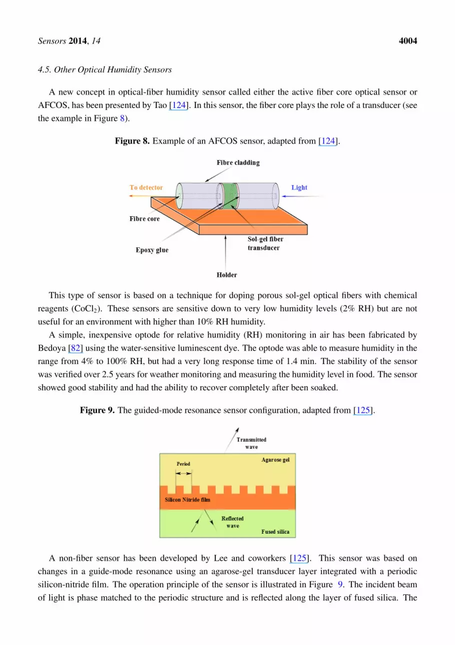
A fast sensor with a linear response has been developed by Gu [79] using a thin-core fiber modalinterferometer with a fiber Bragg grating written in the interior of the interferometer. Poly (N-ethyl-4-vinylpyridinium chloride) and salt of poly-vinyl-sulfonic acid and sodium were used as the hydrophilicmaterial. The FBG was used to compensate for changes in the temperature. The implementation of thephotonic crystal fibre interferometer [100] with FBG and using agarose as the hydrophilic material wasproposed by Mathew et al. [114]. Figure 7 illustrates the scheme of the proposed sensor. This sensorproduced a variation in the detected optical power of over 7 dB for a RH range of 75% and had a lowlevel of temperature-humidity crosstalk. Other sensors based on a LPFGs include: a Mach-Zehnderinterferometer based on cascaded long-period gratings coated with a thin-film of hydro-gel [110]; aMichelson interferometer using a LPFG grating pair formed by coating a mirror at the distal end of theLPFG [104]; and an LPFG using a tailored layered polyimide coating on the grating region [111] wereput into operation. The former detector only operated over a limited (60%–100%) RH range. However,the second and third sensors showed operability over a range of 20%–80% RH, which was wider thanthe range where the former one operated.
4.4. Evanescent Wave Humidity Sensors
The principle of operation of evanescent field humidity sensors (EFHS) is quite simple.Electromagnetic field propagating inside the core of a waveguide do not confined completely insideit [115]. The fraction of the field that is confined inside of the core of a waveguide is called eitherthe guided wave or the guided mode. In the same time, the part of the field that propagates outside ofthe waveguide is called either the evanescent wave or the evanescent field. The guided field and theevanescent field are related by condition of continuity of electromagnetic field on the border betweenthe core and the cladding. This means that the guided field will be affected by any changes that theevanescent field experiences. When some water molecules are absorbed into the hydrophilic materialthe refractive index of the hydrophilic material changes. If the evanescent field propagates inside of the
Sensors 2014, 14 4003
hydrophilic material, this change will affect the evanescent field and can be detected as a change in theguided mode. One of the common way to detect the changes in the evanescent field is, for example, byusing an interferometer [79].
Today, efforts to improve of the performance of EFHS are mainly focused on research into novel,more sensitive hydrophilic materials as, for example, mats of electro-spun nano-fiber [116], layer ofdi-ureasil xerogel containing lithium bits [76,77], titanium dioxide nano-particles [117] or thin film ofsilica sol-gel [118]. In addition, different ways to generate evanescent field were tested, as for example,hetero-core optical fibers [119], no-core fiber structures [120], sub-wavelength diameter fiber taper [90]and multi-modal fibres [121].
Figure 7. Schematic diagram of the hybrid fiber optic sensor system for simultaneousmeasurement of RH and temperature. (SLED—Super luminescent diode. FOC—Fiberoptic circulator. SMF-Single mode fiber. FBG—Fiber Bragg grating. AI-PCFI—Agaroseinfiltrated-photonic crystal fiber interferometer. OSA—Optical spectrum analyzer. Dottedarrows represent the light path), adapted from [114].
Fuke [122] has published the results of synthesis of Ag-polyaniline nano-composite for applicationin a fiber-based humidity sensor using wave absorption spectroscopy. The sensor has been tested andoptimized by varying the size of silver particles and the cladding length. The sensor has been operateover the range of humidity 5%–95% RH. It has been shown that a reduction in the size of the depositedparticles leads to a dramatic improvement in the sensor sensitivity and the speed of response. A similareffect has also been observed for acoustic sensors. However even after optimization, the sensor hadrelatively long response time of 30 s and a recovery time of 90 s.
A humidity sensor based on a multi-mode fiber taper coated with polyvinyl alcohol has beeninvestigated by Li [91]. The principle of operation of this sensor was based on the interaction betweenthe optical evanescent field and the coating along the taper waist. This sensor showed maximumsensitivity of 1.994 µW/% RH over the humidity range 30%–95% RH, fast response of 2 s and smalltemperature crosstalk.
Another interesting result has been published by Lui. In his experiments with regularly alignednano-rods, Liu [123] has showed that a structure based on zinc oxide nano-rods radially grown on asilica fiber allows improved sensitivity of a sensor more than 50 times in comparison with the case of afibre covered with disordered nano-particles of zinc oxide. The sensor showed good sensitivity over awide range (10%–95% RH) of sensing.
Sensors 2014, 14 4004
4.5. Other Optical Humidity Sensors
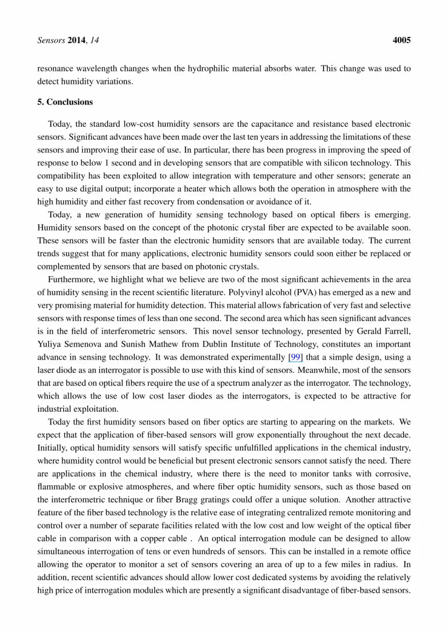
A new concept in optical-fiber humidity sensor called either the active fiber core optical sensor orAFCOS, has been presented by Tao [124]. In this sensor, the fiber core plays the role of a transducer (seethe example in Figure 8).
Figure 8. Example of an AFCOS sensor, adapted from [124].
This type of sensor is based on a technique for doping porous sol-gel optical fibers with chemicalreagents (CoCl2). These sensors are sensitive down to very low humidity levels (2% RH) but are notuseful for an environment with higher than 10% RH humidity.
A simple, inexpensive optode for relative humidity (RH) monitoring in air has been fabricated byBedoya [82] using the water-sensitive luminescent dye. The optode was able to measure humidity in therange from 4% to 100% RH, but had a very long response time of 1.4 min. The stability of the sensorwas verified over 2.5 years for weather monitoring and measuring the humidity level in food. The sensorshowed good stability and had the ability to recover completely after been soaked.
Figure 9. The guided-mode resonance sensor configuration, adapted from [125].
A non-fiber sensor has been developed by Lee and coworkers [125]. This sensor was based onchanges in a guide-mode resonance using an agarose-gel transducer layer integrated with a periodicsilicon-nitride film. The operation principle of the sensor is illustrated in Figure 9. The incident beamof light is phase matched to the periodic structure and is reflected along the layer of fused silica. The
Sensors 2014, 14 4005
resonance wavelength changes when the hydrophilic material absorbs water. This change was used todetect humidity variations.
5. Conclusions
Today, the standard low-cost humidity sensors are the capacitance and resistance based electronicsensors. Significant advances have been made over the last ten years in addressing the limitations of thesesensors and improving their ease of use. In particular, there has been progress in improving the speed ofresponse to below 1 second and in developing sensors that are compatible with silicon technology. Thiscompatibility has been exploited to allow integration with temperature and other sensors; generate aneasy to use digital output; incorporate a heater which allows both the operation in atmosphere with thehigh humidity and either fast recovery from condensation or avoidance of it.
Today, a new generation of humidity sensing technology based on optical fibers is emerging.Humidity sensors based on the concept of the photonic crystal fiber are expected to be available soon.These sensors will be faster than the electronic humidity sensors that are available today. The currenttrends suggest that for many applications, electronic humidity sensors could soon either be replaced orcomplemented by sensors that are based on photonic crystals.
Furthermore, we highlight what we believe are two of the most significant achievements in the areaof humidity sensing in the recent scientific literature. Polyvinyl alcohol (PVA) has emerged as a new andvery promising material for humidity detection. This material allows fabrication of very fast and selectivesensors with response times of less than one second. The second area which has seen significant advancesis in the field of interferometric sensors. This novel sensor technology, presented by Gerald Farrell,Yuliya Semenova and Sunish Mathew from Dublin Institute of Technology, constitutes an importantadvance in sensing technology. It was demonstrated experimentally [99] that a simple design, using alaser diode as an interrogator is possible to use with this kind of sensors. Meanwhile, most of the sensorsthat are based on optical fibers require the use of a spectrum analyzer as the interrogator. The technology,which allows the use of low cost laser diodes as the interrogators, is expected to be attractive forindustrial exploitation.
Today the first humidity sensors based on fiber optics are starting to appearing on the markets. Weexpect that the application of fiber-based sensors will grow exponentially throughout the next decade.Initially, optical humidity sensors will satisfy specific unfulfilled applications in the chemical industry,where humidity control would be beneficial but present electronic sensors cannot satisfy the need. Thereare applications in the chemical industry, where there is the need to monitor tanks with corrosive,flammable or explosive atmospheres, and where fiber optic humidity sensors, such as those based onthe interferometric technique or fiber Bragg gratings could offer a unique solution. Another attractivefeature of the fiber based technology is the relative ease of integrating centralized remote monitoring andcontrol over a number of separate facilities related with the low cost and low weight of the optical fibercable in comparison with a copper cable . An optical interrogation module can be designed to allowsimultaneous interrogation of tens or even hundreds of sensors. This can be installed in a remote officeallowing the operator to monitor a set of sensors covering an area of up to a few miles in radius. Inaddition, recent scientific advances should allow lower cost dedicated systems by avoiding the relativelyhigh price of interrogation modules which are presently a significant disadvantage of fiber-based sensors.

Sensors 2014, 14 4006
Acknowledgments
This work was supported by West Midlands European Regional Development Fund (ERDF) project.Moreover, the authors would like to thank Sergei K. Turitsyn for support and fruitful discussions.
Author Contributions
All authors contributed extensively to the work presented in this paper. Stanislav Kolpakov wrotethe paper and the topic about acoustic sensors. The topic about optical sensors was written byStanislav Kolpakov and Chengbo Mou. Neil Gordon performed simulations and wrote the part aboutelectronic sensors. Kaiming Zhou contributed in sections about acoustic and optical sensing. He alsoprovided his suggestions and corrections during the preparation of the paper.
Conflicts of Interest
The authors declare no conflicts of interest.
References
1. Tatara, T.; Tsuzaki, K. An apnea monitor using a rapid-response hygrometer. J. Clin.Monit. Comput. 1997, 13, 5–9.
2. Lin, Y.C. Breath sensor based on reflective optical lensed fiber. Microw. Opt. Technol. Lett.2013, 55, 450–454.
3. Kastner, W.; Neugschwandtner, G.; Soucek, S.; Newmann, H.M. Communication systems forbuilding automation and control. Proc. IEEE 2005, 93, 1178–1203.
4. Laville, C.; Pellet, C. Interdigitated humidity sensors for a portable clinical microsystem.IEEE Trans. Biomed. Eng. 2002, 49, 1162–1167.
5. Habib Ahsan, A.H.M.; Lange, C.F.; Moussa, W. Development of a Humidity Microsensor withThermal Reset. In Proceedings of the International Conference on MEMS, NANO and SmartSystems, Banff, AB, Canada, 20–23 July 2003; pp. 89–93.
6. Chairperson Publications Board. Guide to Meteorological Instruments and Methods ofObservation, 7th ed.; World Meteorological Organization: Geneva, Switzerland, 2008.
7. Lazarus, N.; Fedder, G.K. Designing a robust high-speed CMOS-MEMS capacitive humiditysensor. J. Micromech. Microeng. 2012, 22, 085021.
8. Mathew, J.; Semenova, Y.; Rajan, G.; Farrell, G. Humidity sensor based on a photonic crystalfibre interferometer. Electron. Lett. 2010, 46, 1341–1343.
9. Favero, F.; Villatoro, J.; Pruneri, V. Microstructured optical fiber interferometric breathing sensor.J. Biomed. Opt. 2012, 17, 037006.
10. Zheng, S.; Zhu, Y.; Krishnaswamy, S. Fiber humidity sensors with high sensitivity and selectivitybased on interior nanofilm-coated photonic crystal fiber long-period gratings. Sens. ActuatorsB Chem. 2013, 176, 264–274.
11. Cardenas-Sevilla, G.; Favero, F.; Villatoro, J. High-visibility photonic crystal fiber interferometeras multifunctional sensor. Sensors 2013, 13, 2349–2358.

Sensors 2014, 14 4007
12. Matko, V.; Koprivnikar, J. Quartz sensor for water absorption measurement in glass-fiber resins.Instrum. Meas. IEEE Trans. 1998, 47, 1159–1162.
13. Matko, V.; Donlagic, D. Sensor for High-Air-Humidity Measurement. In Proceedings of theConference on Precision Electromagnetic Measurements Digest, Braunschweig, Germany, 17–21June 1996; pp. 351–353.
14. Zhang, T.; Mubeen, S.; Myung, N.V.; Deshusses, M.A. Recent progress in carbon nanotube-basedgas sensors. Nanotechnology 2008, 19, 332001.
15. Li, H.; Zhang, J.; Tao, B.; Wan, L.; Gong, W. Investigation of capacitive humidity sensingbehavior of silicon nanowires. Phys. E Low-Dimens. Syst. Nanostruct. 2009, 41, 600–604.
16. Kauffman, D.R.; Star, A. Carbon nanotube gas and vapor sensors. Angew. Chem. Int. Ed. 2008,47, 6550–6570.
17. Yoo, K.P.; Lim, L.T.; Min, N.K.; Lee, M.J.; Lee, C.J.; Park, C.W. Novel resistive-type humiditysensor based on multiwall carbon nanotube/polyimide composite films. Sens. Actuators B Chem.2010, 145, 120–125.
18. Yeow, J.T.W.; She, J.P.M. Carbon nanotube-enhanced capillary condensation for a capacitivehumidity sensor. Nanotechnology 2006, 17, 5441–5448.
19. Steele, J.; Fitzpatrick, G.; Brett, M.J. Capacitive humidity sensors with high sensitivity andsubsecond response times. IEEE Sens. J. 2007, 7, 955–956.
20. Ahmad, Z.; Zafar, Q.; Sulaiman, K.; Akram, R.; Karimov, K.S. A humidity sensingorganic-inorganic composite for environmental monitoring. Sensors 2013, 13, 3615–3624.
21. Bi, H.; Yin, K.; Xie, X.; Ji, J.; Wan, S.; Sun, L.; Terrones, M.; Dresselhaus, M.S. Ultrahighhumidity sensitivity of graphene oxide. Sci. Rep. 2013, doi:10.1038/srep02714.
22. Chen, W.P.; Zhao, Z.G.; Liu, X.W.; Zhang, Z.X.; Suo, C.G. A capacitive humidity sensor basedon multi-wall carbon nanotubes (MWCNTs). Sensors 2009, 9, 7431–7444.
23. Kang, U.; Wise, K. A high-speed capacitive humidity sensor with on-chip thermal reset.IEEE Trans. Electron Devices 2000, 47, 702–710.
24. Kuo, L.S.; Huang, H.H.; Yang, C.H.; Chen, P.H. Real-time remote monitoring of temperatureand humidity within a proton exchange membrane fuel cell using flexible sensors. Sensors 2011,11, 8674–8684.
25. Lee, C.Y.; Su, A.; Liu, Y.C.; Chan, P.C.; Lin, C.H. Sensor fabrication method for in situtemperature and humidity monitoring of light emitting diodes. Sensors 2010, 10, 3363–3372.
26. Ma, R.H.; Wang, Y.H.; Lee, C.Y. Wireless remote weather monitoring system based on MEMStechnologies. Sensors 2011, 11, 2715–2727.
27. Nizhnik, O.; Higuchi, K.; Maenaka, K. A standard CMOS humidity sensor withoutpost-processing. Sensors 2011, 11, 6197–6202.
28. Nizhnik, O.; Higuchi, K.; Maenaka, K. Self-calibrated humidity sensor in CMOS withoutpost-processing. Sensors 2012, 12, 226–232.
29. Yang, M.Z.; Dai, C.L.; Lu, D.H. Polypyrrole porous micro humidity sensor integrated with a ringoscillator circuit on chip. Sensors 2010, 10, 10095–10104.
Sensors 2014, 14 4008
30. Wagner, T.; Krotzky, S.; Weiss, A.; Sauerwald, T.; Kohl, C.D.; Roggenbuck, J.; Tiemann, M.A high temperature capacitive humidity sensor based on mesoporous silica. Sensors 2011,11, 3135–3144.
31. Wang, S.; Xia, G.; He, H.; Yi, K.; Shao, J.; Fan, Z. Structural and optical properties ofnanostructured TiO2 thin films fabricated by glancing angle deposition. J. Alloy. Compd. 2007,431, 287–291.
32. Arshaka, K.; Twomey, K. Thin films of In2O3/SiO for humidity sensing applications. Sensors2002, 2, 205–218.
33. Arshaka, K.; Twomey, K.; Egan, D. A ceramic thick film humidity sensor based on MnZn ferrite.Sensors 2002, 2, 50–61.
34. Kuang, Q.; Lao, C.; Wang, Z.L.; Xie, Z.; Zheng, L. High-sensitivity humidity sensor based on asingle SnO2 nanowire. J. Am. Chem. Soc. 2007, 129, 6070–6071.
35. Lee, S.P. Synthesis and characterization of carbon nitride films for micro humidity sensors.Sensors 2008, 8, 1508–1518.
36. Huang, C.W.; Huang, Y.J.; Lu, S.S.; Lin, C.T. A fully integrated humidity sensor system-on-chipfabricated by micro-stamping technology. Sensors 2012, 12, 11592–11600.
37. Rubinger, C.P.L.; Calado, H.D.R.; Rubinger, R.M.; Oliveira, H.; Donnici, C.L. Characterizationof a sulfonated polycarbonate resistive humidity sensor. Sensors 2013, 13, 2023–2032.
38. Yang, M.Z.; Dai, C.L.; Lin, W.Y. Fabrication and characterization of polyaniline/PVA humiditymicrosensors. Sensors 2011, 11, 8143–8151.
39. Penza, M.; Anisimkin, V.I. Surface acoustic wave humidity sensor using polyvinyl-alcohol film.Sens. Actuators A Phys. 1999, 76, 162–166.
40. Caliendo, C.; Verona, E.; Anisimkin, V.I. Surface acoustic wave humidity sensors: a comparisonbetween different types of sensitive membrane. Smart Mater. Struct. 1997, 6, 707–715.
41. Sauerbrey, G. The use of quartz oscillators for weighing thin layers and for microweighing(In German). Zeitschrift fur Physik 1959, 155, 155–206.
42. Sheng, L.; Chen, D.; Chen, Y. A surface acoustic wave humidity sensor with high sensitivitybased on electrospun MWCNT/Nafion nanofiber films. Nanotechnology 2011, 22, 265504.
43. Lv, X.; Li, Y.; Hong, L.; Luo, D.; Yang, M. A highly water-resistive humidity sensor based onsilicon-containing polyelectrolytes prepared by one-pot method. Sens. Actuators B Chem. 2007,124, 347–351.
44. Li, Y.; Li, P.; Yang, M.; Lei, S.; Chen, Y.; Guo, X. A surface acoustic wave humidity sensorbased on electrosprayed silicon-containing polyelectrolyte. Sens. Actuators B Chem. 2010,145, 516–520.
45. Penza, M.; Cassano, G. Relative humidity sensing by PVA-coated dual resonator SAW oscillator.Sens. Actuators B Chem. 2000, 68, 300–306.
46. Braga, E.; Nakano, A.; da Cunha, M. A SAW Resonator Sensor System Employed in HumidityMeasurements. In Proceedings of the International Microwave and Optoelectronics Conference(SBMO/IEEE MTT-S, APS and LEOS-IMOC’99), Rio de Janeiro, Brazil, 9–12 August 1999;Volume 1, pp. 342–345.

Sensors 2014, 14 4009
47. Kawalec, A.; Pasternak, M. A new high-frequency surface acoustic wave sensor for humiditymeasurement. Instrum. Meas. IEEE Trans. 2008, 57, 2019–2023.
48. Kawalec, A.; Jasek, K.; Pasternak, M. Measurements results of SAW humidity sensor with nafionlayer. Eur. Phys. J. Spec. Top. 2008, 154, 123–126.
49. Rimeika, R.; Ciplys, D.; Poderys, V.; Rotomskis, R.; Shur, M. Humidity Sensor Using LeakySurface Acoustic Waves in YX-LiTaO3 with Nanostructured Porphyrin Film. In Proceedings ofthe 2009 IEEE on Sensors, Christchurch, New Zealand, 25–28 October 2009; pp. 1753–1757.
50. Zhu, Y.; Yuan, H.; Xu, J.; Xu, P.; Pan, Q. Highly stable and sensitive humidity sensors based onquartz crystal microbalance coated with hexagonal lamelliform monodisperse mesoporous silicaSBA-15 thin film. Sens. Actuators B Chem. 2010, 144, 164–169.
51. Zhou, X.; Jiang, T.; Zhang, J.; Wang, X.; Zhu, Z. Humidity sensor based on quartz tuning forkcoated with solgel-derived nanocrystalline zinc oxide thin film. Sens. Actuators B Chem. 2007,123, 299–305.
52. Shinbo, K.; Otuki, S.; Kanbayashi, Y.; Ohdaira, Y.; Baba, A.; Kato, K.; Kaneko, F.;Miyadera, N. A hybrid humidity sensor using optical waveguides on a quartz crystalmicrobalance. Thin Solid Films 2009, 518, 629–633.
53. Su, P.G.; Sun, Y.L.; Lin, C.C. A low humidity sensor made of quartz crystal microbalance coatedwith multi-walled carbon nanotubes/Nafion composite material films. Sens. Actuators B Chem.2006, 115, 338–343.
54. Su, P.G.; Chang, Y.P. Low-humidity sensor based on a quartz-crystal microbalance coated withpolypyrrole/Ag/TiO2 nanoparticles composite thin films. Sens. Actuators B Chem. 2008, 129,915–920.
55. Wang, X.; Ding, B.; Yu, J.; Wang, M.; Pan, F. A highly sensitive humidity sensor based on ananofibrous membrane coated quartz crystal microbalance. Nanotechnology 2010, 21, 055502.
56. Wang, X.H.; Ding, Y.F.; Zhang, J.; Zhu, Z.Q.; You, S.Z.; Chen, S.Q.; Zhu, J. Humidity sensitiveproperties of ZnO nanotetrapods investigated by a quartz crystal microbalance. Sens. ActuatorsB Chem. 2006, 115, 421–427.
57. Zhang, Y.; Yu, K.; Xu, R.; Jiang, D.; Luo, L.; Zhu, Z. Quartz crystal microbalance coated withcarbon nanotube films used as humidity sensor. Sens. Actuators A Phys. 2005, 120, 142–146.
58. Zhang, Y.; Yu, K.; Ouyang, S.; Luo, L.; Hu, H.; Zhang, Q.; Zhu, Z. Detection of humidity basedon quartz crystal microbalance coated with ZnO nanostructure films. Phys. B Condens. Matter2005, 368, 94–99.
59. Zhou, X.; Zhang, J.; Jiang, T.; Wang, X.; Zhu, Z. Humidity detection by nanostructured ZnO:A wireless quartz crystal microbalance investigation. Sens. Actuators A Phys. 2007, 135,209–214.
60. Fu, J.; Ayazi, F. Dual-Mode Piezo-on-Silicon Resonant Temperature and Humidity Sensor forPortable Air Quality Monitoring Systems. In Proceedings of the 2010 IEEE on Sensors, Kona,HI, USA, 1–4 November 2010; pp. 2131–2135.
61. Qiu, X.; Wang, Z.; Zhu, J.; Oiler, J.; Tang, R.; Yu, C.; Yu, H. The effects of relative humidityand reducing gases on the temperature coefficient of resonant frequency of ZnO based film bulkacoustic wave resonator. IEEE Trans. Ultrason. Ferroelectr. Freq. Control 2010, 57, 1902–1905.

Sensors 2014, 14 4010
62. Tashtoush, N.M.; Cheeke, J.D.N.; Eddy, N. Surface acoustic wave humidity sensor based on athin PolyXIO film. Sens. Actuators B Chem. 1998, 49, 516–520.
63. Li, Y.; Yang, M.J.; Ling, M.F.; Zhu, Y.H. Surface acoustic wave humidity sensors based onpoly(p-diethynylbenzene) and sodium poly sulfone sulfonate. Sens. Actuators B Chem. 2007,122, 560–563.
64. Penza, M.; Cassano, G.; Sergi, A.; Sterzo, C.L.; Russo, M.V. SAW chemical sensing usingpoly-ynes and organometallic polymer films. Sens. Actuators B Chem. 2001, 81, 88–98.
65. Levit, N.; Pestov, D.; Tepper, G. High surface area polymer coatings for SAW-based chemicalsensor applications. Sens. Actuators B Chem. 2002, 82, 241–249.
66. Li, Y.; Li, P.; Yanga, M.; Lei, S.; Chenb, Y.; Guoc, X. A surface acoustic wave humidity sensorbased on electrosprayed silicon-containing polyelectrolyte. Sens. Actuators B Chem. 2010, 145,516–520.
67. Shen, C.Y.; Huang, C.P.; Huang, W. Gas-detecting properties of surface acoustic wave ammoniasensors. Sens. Actuators B Chem. 2004, 101, 1–7.
68. Sarkar, S.; Levit, N.; Tepper, G. Deposition of polymer coatings onto SAW resonators using ACelectrospray. Sens. Actuators B Chem. 2006, 114, 756–761.
69. Buvailo, A.; Xing, Y.; Hines, J.; Borguet, E. Thin polymer film based rapid surface acoustic wavehumidity sensors. Sens. Actuators B Chem. 2011, 156, 444–449.
70. Consales, M.; Buosciolo, A.; Cutolo, A.; Breglio, G.; Irace, A.; Buontempo, S.; Petagna, P.;Giordano, M.; Cusano, A. Fiber optic humidity sensors for high-energy physics applications atCERN. Sens. Actuators B Chem. 2011, 159, 66–74.
71. Garcia-Diego, F.J.; Fernandez-Navajas, A.; Beltran, P.; Merello, P. Study of the effect ofthe strategy of heating on the mudejar church of Santa Maria in Ateca (Spain) for preventiveconservation of the altarpiece surroundings. Sensors 2013, 13, 11407–11423.
72. Lin, Y.C. Breath sensor based on reflective optical lensed fiber. Microw. Opt. Technol. Lett.2013, 55, 450–454.
73. Xu, L.; Fanguy, J.C.; Soni, K.; Tao, S. Optical fiber humidity sensor based onevanescent-wavescattering. Opt. Lett. 2004, 29, 1191–1193.
74. Yeo, T.; Sun, T.; Grattan, K.; Parry, D.; Lade, R.; Powell, B. Polymer-coated fiber Bragg gratingfor relative humidity sensing. IEEE Sens. J. 2005, 5, 1082–1089.
75. Huang, X.; Sheng, D.; Cen, K.; Zhou, H. Low-cost relative humidity sensor based onthermoplastic polyimide-coated fiber Bragg grating. Sens. Actuators B Chem. 2007, 127,518–524.
76. Barbosa, P.C.; Silva, M.M.; Smith, M.J.; Goncalves, A.; Fortunato, E.; Nunes, S.C.;de Zea Bermudez, V. Di-ureasil xerogels containing lithium bis(trifluoromethanesulfonyl)imidefor application in solid-state electrochromic devices. Electrochim. Acta 2009, 54, 1002–1009.
77. Correia, S.F.; Antunes, P.; Pecoraro, E.; Lima, P.P.; Varum, H.; Carlos, L.D.; Ferreira, R.A.;Andre, P.S. Optical fiber relative humidity sensor based on a FBG with a di-ureasil coating.Sensors 2012, 12, 8847–8860.
Sensors 2014, 14 4011
78. Berruti, G.; Consales, M.; Giordano, M.; Sansone, L.; Petagna, P.; Buontempo, S.;Breglio, G.; Cusano, A. Radiation hard humidity sensors for high energy physics applicationsusing polyimide-coated fiber Bragg gratings sensors. Sens. Actuators B Chem. 2013, 177,94–102.
79. Gu, B.; Yin, M.; Zhang, A.P.; Qian, J.; He, S. Optical fiber relative humidity sensor based onFBG incorporated thin-core fiber modal interferometer. Opt. Express 2011, 19, 4140–4146.
80. Mathew, J.; Semenova, Y.; Farrell, G. Relative humidity sensor based on an agarose-infiltratedphotonic crystal fiber interferometer. IEEE J. Sel. Top. Quantum Electron. 2012, 18, 1553–1559.
81. Chen, L.H.; Li, T.; Chan, C.C.; Menon, R.; Balamurali, P.; Shaillender, M.; Neu, B.;Ang, X.M.; Zu, P.; Wong, W.C.; et al. Chitosan based fiber-optic Fabry-Perot humidity sensor.Sens. Actuators B Chem. 2012, 169, 167–172.
82. Bedoya, M.; Dez, M.T.; Moreno-Bondi, M.C.; Orellana, G. Humidity sensing with a luminescentRu(II) complex and phase-sensitive detection. Sens. Actuators B Chem. 2006, 113, 573– 581.
83. Aneesh, R.; Khijwania, S.K. Zinc oxide nanoparticle-doped nanoporous solgel fiber as a humiditysensor with enhanced sensitivity and large linear dynamic range. Appl. Opt. 2013, 52, 5493–5499.
84. Corres, J.; Matias, I.; Hernaez, M.; Bravo, J.; Arregui, F. Optical fiber humidity sensors usingnanostructured coatings of SiO2 nanoparticles. IEEE Sens. J. 2008, 8, 281–285.
85. Estella, J.; de Vicente, P.; Echeverra, J.C.; Garrido, J.J. A fibre-optic humidity sensor based on aporous silica xerogel film as the sensing element. Sens. Actuators B Chem. 2010, 149, 122–128.
86. Noor, M.Y.M.; Khalili, N.; Skinner, I.; Peng, G.D. Optical relative humidity sensor based on ahollow core-photonic bandgap fiber. Meas. Sci. Technol. 2012, 23, 085103.
87. Rivero, P.J.; Urrutia, A.; Goicoechea, J.; Arregui, F. Optical fiber humidity sensors based onLocalized Surface Plasmon Resonance (LSPR) and Lossy-mode resonance (LMR) in overlaysloaded with silver nanoparticles. Sens. Actuators B Chem. 2012, 173, 244–249.
88. Wang, B.; Zhang, F.; Pang, F.; Wang, T. An Optical Fiber Humidity Sensor Based on OpticalAbsorption. In Proceedings of the 2011 Asia Communications and Photonics Conference andExhibition (ACP 2011), Shanghai, China, 13–16 September, 2011; pp. 1–6.
89. Mathew, J.; Semenova, Y.; Farrell, G. A fiber bend based humidity sensor with a wide linear rangeand fast measurement speed. Sens. Actuators A Phys. 2012, 174, 47–51.
90. Zhang, L.; Gu, F.; Lou, J.; Yin, X.; Tong, L. Fast detection of humidity with asubwavelength-diameter fiber taper coated with gelatin film. Opt. Express 2008, 16,13349–13353.
91. Li, T.; Dong, X.; Chan, C.C.; Zhao, C.L.; Zu, P. Humidity sensor based on a multimode-fibertaper coated With polyvinyl alcohol interacting with a fiber bragg grating. IEEE Sens. J. 2012,12, 2205–2208.
92. Miao, Y.; Liu, B.; Zhang, H.; Li, Y.; Zhou, H.; Sun, H.; Zhang, W.; Zhao, Q. Relative humiditysensor based on tilted fiber bragg grating with polyvinyl alcohol coating. IEEE PhotonicsTechnol. Lett. 2009, 21, 441–443.
93. Yeo, T.L.; Sun, T.; Grattan, K.T.V.; Parry, D.; Lade, R.; Powell, B.D. Characterisation of apolymer-coated fibre Bragg grating sensor for relative humidity sensing. Sens. Actuators B Chem.2005, 110, 148–156.
Sensors 2014, 14 4012
94. Wong, W.C.; Chan, C.C.; Chen, L.H.; Li, T.; Lee, K.X.; Leong, K.C. Polyvinyl alcohol coatedphotonic crystal optical fiber sensor for humidity measurement. Sens. Actuators B Chem. 2012,174, 563–569.
95. Zhang, C.; Zhang, W.; Webb, D.J.; Peng, G.D. Optical fibre temperature and humidity sensor.Electron. Lett. 2010, 46, 643.
96. Viegas, D.; Goicoechea, J.; Corres, J.M.; Santos, J.L.; Ferreira, L.A.; Araujo, F.M.; Matias, I.R.A fibre optic humidity sensor based on a long-period fibre grating coated with a thin film of SiO2
nanospheres. Meas. Sci. Technol. 2009, 20, 034002.97. Favero, F.C.; Villatoro, J.; Pruneri, V. Microstructured optical fiber interferometric breathing
sensor. J. Biomed. Opt. 2012, 17, 037006.98. Chen, L.H.; Chan, C.C.; Li, T.; Shaillender, M.; Neu, B.; Balamurali, P.; Menon, R.; Zu, P.;
Ang, X.M.;Wong, W.C.; et al. Chitosan-coated polarization maintaining relative humiditymeasurement. IEEE J. Sel. Top. Quantum Electron. 2012, 18, 1597–1604.
99. Mathew, J.; Semenova, Y.; Farrell, G. A Miniature Optical Humidity Sensor. In Proceedings ofthe 2011 IEEE Sensors Proceedings, Limerick, Ireland, 28–31 October 2011; pp. 2030–2033.
100. Mathew, J.; Semenova, Y.; Rajan, G.; Farrell, G. Humidity sensor based on photonic crystal fibreinterferometer. Electron. Lett. 2010, 46, 1341.
101. Liang, H.; Jin, Y.; Wang, J.; Dong, X.; Street, X.; Higher, X.; Zone, E. Relative humidity sensorbased on polarization maintainig fiber. Microw. Opt. Technol. Lett. 2012, 54, 2364–2366.
102. Ivanov, O.; Nikitov, S.; Gulyaev, Y. Cladding modes of optical fibers: properties and applications.Phys.-Uspekhi 2006, 49, 167–191.
103. Vasil’ev, S.A.; Dianov, E.M.; Medvedkov, O.I.; Protopopov, V.N.; Costantini, D.M.; Iocco, A.;Limberger, H.G.; Salathe, R.P. Properties of the cladding modes of an optical fibre excited byrefractive-index gratings. Quantum Electron. 1999, 29, 65.
104. Alwis, L.; Sun, T.; Grattan, K.T.V. Fibre optic long period grating-based humidity sensor probeusing a Michelson interferometric arrangement. Sens. Actuators B Chem. 2013, 178, 694–699.
105. Erdogan, T. Cladding-mode resonances in short- and long-period fiber grating filters. J. Opt. Soc.Am. A 1997, 14, 1760–1773.
106. Fu, M.; Lin, G.; Liu, W.; Wu, C. Fiber-optic humidity sensor based on an air-gap long periodfiber grating. Opt. Rev. 2011, 18, 93–95.
107. Konstantaki, M.; Pissadakis, S.; Pispas, S.; Madamopoulos, N.; Vainos, N. Optical fiberlong-period grating humidity sensor with poly(ethylene oxide)/cobalt chloride coating. Appl. Opt.2006, 45, 4567–4571.
108. Smietana, M.; Korwin-Pawlowski, M.L.; Bock, W.J.; Pickrell, G.R.; Szmidt, J. Refractive indexsensing of fiber optic long-period grating structures coated with a plasma deposited diamond-likecarbon thin film. Meas. Sci. Technol. 2008, 19, 085301.
109. Wang, L.; Liu, Y.; Zhang, M.; Tu, D.; Mao, X.; Liao, Y. A relative humidity sensor using ahydrogel-coated long period grating. Meas. Sci. Technol. 2007, 18, 3131–3134.
110. Yu, X.; Childs, P.; Zhang, M.; Liao, Y.; Ju, J.; Jin, W. Relative humidity sensor based on cascadedlong-period gratings with hydrogel coatings and fourier demodulation. Photonics Technol.Lett. IEEE 2009, 21, 1828–1830.

Sensors 2014, 14 4013
111. Alwis, L.; Sun, T.; Grattan, K.T.V. Analysis of polyimide-coated optical fiber long-periodgrating-based relative humidity sensor. IEEE Sens. J. 2013, 13, 767–771.
112. Venugopalan, T.; Sun, T.; Grattan, K. Long period grating-based humidity sensor for potentialstructural health monitoring. Sens. Actuators A Phys. 2008, 148, 57–62.
113. Viegas, D.; Goicoechea, J.; Santos, J.L.; Araujo, F.M.; Ferreira, L.A.; Arregui, F.J.; Matias, I.R.Sensitivity improvement of a humidity sensor based on silica nanospheres on a long-period fibergrating. Sensors 2009, 9, 519–527.
114. Mathew, J.; Semenova, Y.; Farrell, G. Fiber optic hybrid device for simultaneous measurement ofhumidity and temperature. IEEE Sens. J. 2013, 13, 1632–1636.
115. Marcuse, D. Theory of Dielectric Optical Waveguides, 2nd ed.; Academic Press: Boston, MA,USA, 1991.
116. Urrutia, A.; Goicoechea, J.; Rivero, P.J.; Matıas, I.R.; Arregui, F.J. Electrospun nanofiber matsfor evanescent optical fiber sensors. Sens. Actuators B Chem. 2013, 176, 569–576.
117. Aneesh, R.; Khijwania, S.K. Titanium dioxide nanoparticle based optical fiber humidity sensorwith linear response and enhanced sensitivity. Appl. Opt. 2012, 51, 2164–2171.
118. Zhao, Z.; Duan, Y. A low cost fiber-optic humidity sensor based on silica sol-gel film.Sens. Actuators B Chem. 2011, 160, 1340–1345.
119. Akita, S.; Sasaki, H.; Watanabe, K.; Seki, A. A humidity sensor based on a hetero-core opticalfiber. Sens. Actuators B Chem. 2010, 147, 385–391.
120. Xia, L.; Li, L.; Li, W.; Kou, T.; Liu, D. Novel optical fiber humidity sensor based on a no-corefiber structure. Sens. Actuators A Phys. 2013, 190, 1–5.
121. Zhao, Y.; Jin, Y.; Liang, H. All-Fiber-Optic Sensor for Relative Humidity Measurement. InProceedings of the 2011 International Conference on Electronics and Optoelectronics (ICEOE),Dalian, China, 29–31 July 2011; pp. 83–86.
122. Fuke, M.V.; Kanitkar, P.; Kulkarni, M.; Kale, B.B.; Aiyer, R.C. Effect of particle size variation ofAg nanoparticles in Polyaniline composite on humidity sensing. Talanta 2010, 81, 320–326.
123. Liu, Y.; Zhang, Y.; Lei, H.; Song, J.; Chen, H.; Li, B. Growth of well-arrayed ZnO nanorods onthinned silica fiber and application for humidity sensing. Opt. Express 2012, 20, 19404–19411.
124. Tao, S.; Winstead, C.; Jindal, R.; Singh, J. Optical-fiber sensor using tailored porous sol-gel fibercore. IEEE Sens. J. 2004, 4, 322–328.
125. Lee, K.; Wawro, D.; Priambodo, P.; Magnusson, R. Agarose-gel based guided-mode resonancehumidity sensor. IEEE Sens. J. 2007, 7, 409–414.
c© 2014 by the authors; licensee MDPI, Basel, Switzerland. This article is an open access articledistributed under the terms and conditions of the Creative Commons Attribution license(http://creativecommons.org/licenses/by/3.0/).