timing shift of optical pulses due to inter-channel cross-talk
TRANSCRIPT
Progress In Electromagnetics Research M, Vol. 1, 21–30, 2008
TIMING SHIFT OF OPTICAL PULSES DUE TOINTER-CHANNEL CROSS-TALK
B. Stojanovic and D. M. Milovic
Faculty of Electronic EngineeringDepartment of TelecommunicationsUniversity of NisAleksandra Medvedeva 14, 1800 Nis, Serbia
A. Biswas
Center for Research and Education in Optical Sciences andApplicationsDepartment of Applied Mathematics and Theoretical PhysicsDelaware State UniversityDover, DE 19901-2277, USA
Abstract—This paper considers the influence of interchannel crosstalkon pulse timing shift and optical power due to the propagation ofoptical pulse through a nonlinear dispersive fiber. The numericalresults are shown. An influencing parameter of the pulse distortionthrough the fiber is the eye opening penalty.
1. INTRODUCTION
In the modern times in telecommunications systems, the usageof optical fibers is a good transmission medium [1–20]. Theoptical wavelength-division-system (WDM) consists of a transmitter,transmission medium and a receiver and almost every component inthe entire system introduces crosstalk. Optical crosstalk has a greatinfluence on transmission quality and it may occur due to reflections,fiber and amplifier nonlinearities, add-drop components, multiplexersand de-multiplexers in WDM etc. There are numerous reasons for thecrosstalk. One reason is the imperfection of the transmitter and asystem of mirrors that are reflecting the beam into the optical fiberwhich leads to the possibility of interference of unwanted pulse at a

22 Stojanovic, Milovic, and Biswas
different frequency that interact with the useful signal. Another reasonfor crosstalk is induced by leakage or insufficient insulation.
In this paper, the influence of interchannel crosstalk timing shiftand optical power on the propagation of the optical solitons through asingle mode nonlinear dispersive optical fiber is considered. Both thecrosstalk and the useful signal are Gaussian shape but with differentwavelengths. The pulse distortion through the fiber for differentcrosstalk optical powers and crosstalk timing shifts.
2. DETERMINATION OF USEFUL SIGNALINFLUENCED BY CROSS-TALK SIGNAL
The propagation of short optical pulses in nonlinear dispersive mediumis considered. The cross-talk pulses being at different wavelengths thanuseful signal, so called interchannel cross-talk distort the useful pulses.It is assumed that the cross-talk occur at the transmitter output (fiberinput). The useful signal is modeled as
s1(z, T ) = A1(0, T ) cos (ω1T ) (1)
while the interchannel cross-talk signals is considered to be given by
s2(z, T ) = A2(0, T ) cos (ω2T ) (2)
where ω1 is the central frequency of a desired channel and ω2 representsthe central frequency of interchannel cross-talk.
In this paper, the input optical pulse envelope is assumed to beunchirped whose shape is given by
A1(0, T ) =√
P1f
(− T 2
2T 20
)(3)
The envelope of the interchannel cross-talk pulse is assumed to be givenby
A2(0, T ) =√
P2f
{−(T − Ts)
2
2T 20
}(4)
where P1 and P2 are the peak powers of useful optical pulse andinterchannel cross-talk, respectively and Ts is the interchannel cross-talk time shift. Also f represents the pulse shape. It could be Gaussian,super-Gaussian, sech or super-sech as the case may be. It is assumedthat −Tb/2 ≤ Ts ≤ Tb/2 as in this paper the interest is confined to onebit period Tb.
Progress In Electromagnetics Research M, Vol. 1, 2008 23
The useful optical pulse and the above modeled interchannelcross-talk will co-propagate simultaneously through the optical fiber.This propagation is governed by the set of two coupled nonlinearSchrodinger’s equation which, in the dimensionless form, is given by
∂A1
∂z+
i
2β21
∂2A1
∂T 2= iγ1
(|A1|2 + 2 |A2|2
)A1 (5)
∂A2
∂z+
i
2β22
∂2A2
∂T 2= iγ2
(|A2|2 + 2 |A1|2
)A2 (6)
where γj = n2ωj/cAeff and β2j = −Dλ2j/2πc for j = 1, 2 are
the coefficients of dispersion and nonlinear terms respectively andT = t − z/vg is the normalization factor. Also Aeff = πw2 is theeffective core area. It needs to be noted that Aeff is typically 10−20 µm2
in the visible region but it can be in the range of 50–80µm2 in the1.55µm region, so that γ can vary over the range 2–30 W−1km−1
depending on n2 and frequency. Also it is assumed that the fiberlosses are small and therefore neglected.
The coupled equations in (5) and (6) is a nonlinear partialdifferential equation. This system is solved by using the split-stepFourier method that is extensively used in solving pulse propagationproblem in a nonlinear dispersive medium. In a lot of cases thismethod shows high accuracy. Although, in general, the dispersion andnonlinearity act together along the fiber, the split-step Fourier methodgives an approximate solution by assuming that in the propagation ofoptical field over a small distance h one can pretend that dispersiveand nonlinear effects act independently. Hence, propagation from z toz + h is carried out in two steps. In the first step, nonlinearity actsalone while in the second step dispersion acts alone. Thus the namesplit-step method. Although the method is relatively straightforwardto implement, it should be noted that it requires the step size h along zand time discretization to be selected carefully to maintain the requiredaccuracy.
The interchannel cross-talk level is defined by signal-to-interference ratio (SIR) i.e., the ratio of useful signal optical powerto cross-talk to cross-talk signal optical power. It is defined as
SIR = 20 logP1
P2(7)
3. NUMERICAL SIMULATION OF PULSE EVOLUTION
Pulse evolution pictures and dependences of useful optical pulsedistortion from timing shifts (Ts) and SIR are considered in this section.
24 Stojanovic, Milovic, and Biswas
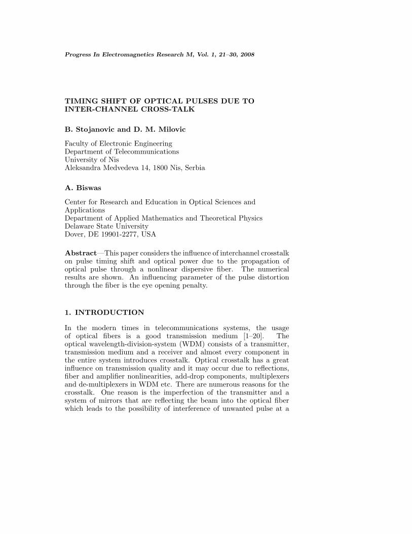
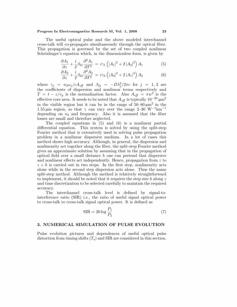
In the propagation of optical pulses, the following factors are taken intoconsideration TFWHM = 12.5 ps, λ1 = 1550 nm, bit rate R = 20 Gb/s,P − 1 = 50 mW through the SMF in the regime of normal dispersion(D = 0.2 ps/nm-km) with parameter Aeff = 50 µm2. The interchannelcross-talk wavelength is taken to be λ2 = 1551.5 nm. The fiber lengthis taken to be 60 km in all the simulations.
The contour plot is used as a very illustrative way to showvariations of power and distortion of pulse during propagation throughthe nonlinear dispersive SMF. In the worst case SIR = 0 dB, i.e., theuseful signal has an equal magnitude to cross-talk signal, is considered.
0 50 100 150 2000
10
20
30
40
50
60
Figure 1. Pulse evolution picture and corresponding contour plot(Gaussian pulse).
0 50 100 150 2000
10
20
30
40
50
60
Figure 2. Pulse evolution picture and corresponding contour plot(super-Gaussian pulse).

Progress In Electromagnetics Research M, Vol. 1, 2008 25
0 50 100 150 2000
10
20
30
40
50
60
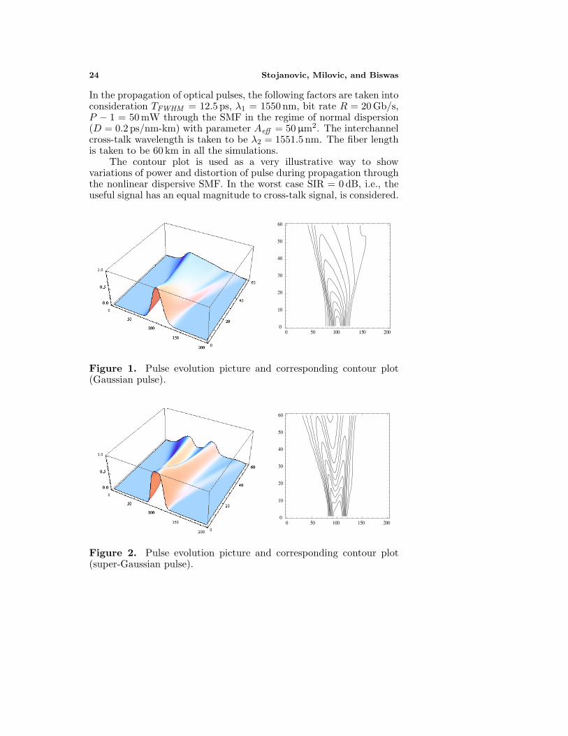
Figure 3. Pulse evolution picture and corresponding contour plot(sech pulse).
0 50 100 150 2000
10
20
30
40
50
60
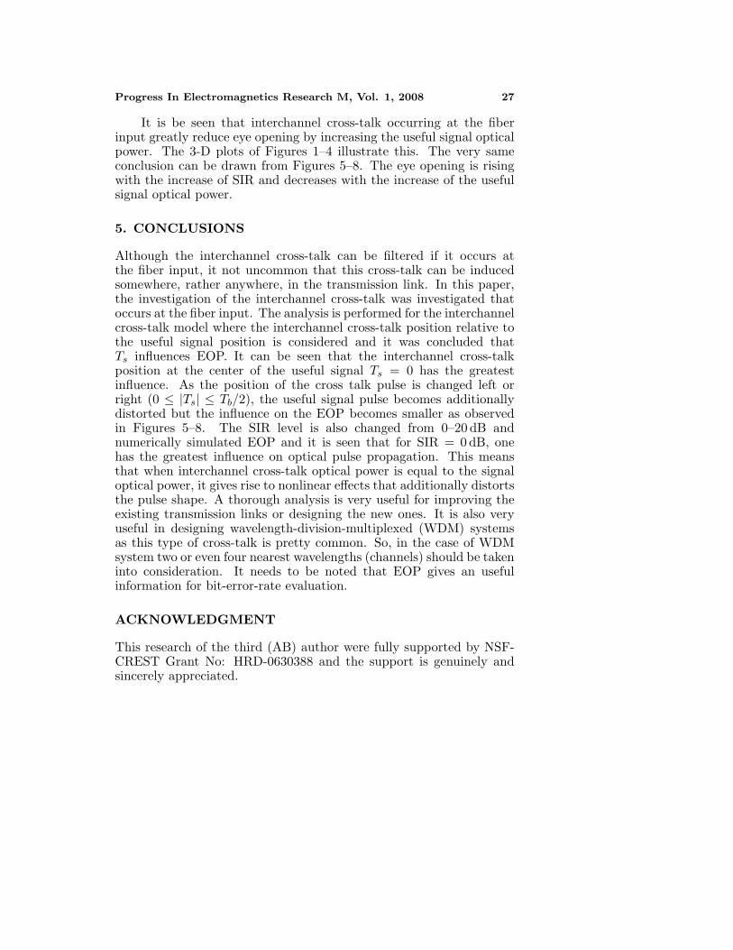
Figure 4. Pulse evolution picture and corresponding contour plot(super-sech pulse).
These figures are respectively due to Gaussian, super-Gaussian,sech and super-sech pulses.
4. EYE OPENING PENALTY
The influence of crosstalk occurring at the input of transmissionlink is obtained by estimating the eye opening penalty (EOP). TheEOP is a performance measure considering the dynamic propagationeffects, such as the dispersion, nonlinearities and other such nonlinearinfluences that distort the pulse shape. The EOP is especially usefulfor noise-free system evaluations, as it gives an useful measure of

26 Stojanovic, Milovic, and Biswas
deterministic pulse distortion effects. EOP is defined as a ratio ofan initial eye opening (EObefore) to the eye opening after transmission(EOafter ). The initial eye opening is the eye opening that is measuredat the fiber input.
The analysis of the influence of interchannel crosstalk occurringat the fiber input for a different useful signal optical powers and forthe worst case when SIR = 0 dB by estimating the EOP and changingTs. The influence of interchannel cross-talk by estimating EOP andchanging SIR is also analysed in Figures 5–8, for various types of pulses.
-0.4Tb -0.2Tb 0.0Tb 0.2Tb 0.4Tb
1
2
3
4
5
6
7
8
9
10
11
EO
P
Ts
SIR=0 dB SIR=5 dB SIR=10 dB
Pm=50mW
Figure 5. EOP vs Ts for Gaus-sian optical pulse and differentSIR.
-0.4Tb -0.2Tb 0.0Tb 0.2Tb 0.4Tb
0123456789
101112131415161718
EO
P
Ts
SIR= 0 dB SIR=5 dB SIR=10 dB
Pm=50mW
Figure 6. EOP vs Ts forsuper-Gaussian optical pulse anddifferent SIR.
-0.4Tb -0.2Tb 0.0Tb 0.2Tb 0.4Tb
0
2
4
6
8
10
EO
P
Ts
SIR=0 dB SIR=5 dB SIR=10 dB
Pm=50mW
Figure 7. EOP vs Ts for sechoptical pulse and different SIR.
-0.4Tb -0.2Tb 0.0Tb 0.2Tb 0.4Tb
2
3
4
5
6
7
8
9
10
11
12
13
EO
P
Ts
SIR=0 dB SIR=5 dB SIR=10 dB
Pm=50mW
Figure 8. EOP vs Ts forfor super-sech optical pulse anddifferent SIR.
Progress In Electromagnetics Research M, Vol. 1, 2008 27
It is be seen that interchannel cross-talk occurring at the fiberinput greatly reduce eye opening by increasing the useful signal opticalpower. The 3-D plots of Figures 1–4 illustrate this. The very sameconclusion can be drawn from Figures 5–8. The eye opening is risingwith the increase of SIR and decreases with the increase of the usefulsignal optical power.
5. CONCLUSIONS
Although the interchannel cross-talk can be filtered if it occurs atthe fiber input, it not uncommon that this cross-talk can be inducedsomewhere, rather anywhere, in the transmission link. In this paper,the investigation of the interchannel cross-talk was investigated thatoccurs at the fiber input. The analysis is performed for the interchannelcross-talk model where the interchannel cross-talk position relative tothe useful signal position is considered and it was concluded thatTs influences EOP. It can be seen that the interchannel cross-talkposition at the center of the useful signal Ts = 0 has the greatestinfluence. As the position of the cross talk pulse is changed left orright (0 ≤ |Ts| ≤ Tb/2), the useful signal pulse becomes additionallydistorted but the influence on the EOP becomes smaller as observedin Figures 5–8. The SIR level is also changed from 0–20 dB andnumerically simulated EOP and it is seen that for SIR = 0 dB, onehas the greatest influence on optical pulse propagation. This meansthat when interchannel cross-talk optical power is equal to the signaloptical power, it gives rise to nonlinear effects that additionally distortsthe pulse shape. A thorough analysis is very useful for improving theexisting transmission links or designing the new ones. It is also veryuseful in designing wavelength-division-multiplexed (WDM) systemsas this type of cross-talk is pretty common. So, in the case of WDMsystem two or even four nearest wavelengths (channels) should be takeninto consideration. It needs to be noted that EOP gives an usefulinformation for bit-error-rate evaluation.
ACKNOWLEDGMENT
This research of the third (AB) author were fully supported by NSF-CREST Grant No: HRD-0630388 and the support is genuinely andsincerely appreciated.
28 Stojanovic, Milovic, and Biswas
REFERENCES
1. Biswas, A., “Dispersion-managed solitons in optical fibres,”Journal of Optics A, Vol. 4, No. 1, 84–97, 2002.
2. Biswas, A. and S. Konar, Introduction to Non-Kerr Law OpticalSolitons, CRC Press, Boca Raton, FL, 2006.
3. Biswas, A., S. Konar, and E. Zerrad. “Soliton-soliton interactionwith parabolic law nonlinearity,” Journal of ElectromagneticWaves and Applications. Vol. 20, No. 7, 927–939, 2006.
4. Biswas, A., Shwetanshumala, and S. Konar, “Dynamically stabledispersion-managed optical solitons with parabolic law nonlinear-ity,” Journal of Electromagnetic Waves and Applications, Vol. 20,No. 9, 1249–1258, 2006.
5. Biswas, A., “Stochastic perturbation of parabolic law opticalsolitons,” Journal of Electromagnetic Waves and Applications,Vol. 21, No. 11, 1479–1488, 2007.
6. Gangwar, R., S. P. Singh, and N. Singh, “Soliton basedoptical communication,” Progress In Electromagnetics Research,PIER 74, 157–166, 2007.
7. Hirooka, T. and S. Wabnitz, “Nonlinear gain control ofdispersion-managed soliton amplitude and collisions,” OpticalFiber Technology, Vol. 6, No. 2, 109–121, 2000.
8. Jana, S. and S. Konar, “Tunable spectral switching in far field witha chirped cosh-Gaussian pulse,” Optics Communications, Vol. 267,No. 1, 24–31, 2006.
9. Jana, S. and S. Konar, “A new family of Thirring typeoptical spatial solitons via electromagnetic induced transparency,”Physics Letters A, Vol. 362, No. 5–6, 435–438, 2007.
10. Jovanoski, Z. and D. R. Rowland, “Variational analysis of solitarywaves in a homogenous cubic-quintic nonlinear medium,” Journalof Modern Optics, Vol. 48, No. 7, 1179–1193, 2001.
11. Kohl, R., A. Biswas, D. Milovic, and E. Zerrad, “Optical solitonperturbation in a non-Kerr law media,” To appear in Optics andLaser Technology.
12. Konar, S. and A. Sengupta, “Propagation of an elliptic Gaussianlaser beam in a medium with saturable nonlinearity,” Journal ofOptical Society of America B, Vol. 11, No. 9, 1644–1646, 1994.
13. Konar, S., J. Kumar, and P. K. Sen, “Suppression of solitoninstability by higher order nonlinearity in long-haul opticalcommunication systems,” Journal of Nonlinear Optical Physicsand Materials, Vol. 8, No. 4, 497–502, 1999.
Progress In Electromagnetics Research M, Vol. 1, 2008 29
14. Konar, S. and S. Jana, “Linear and nonlinear propagation of sinh-Gaussian pulses in dispersive media possessing Kerr nonlinearity,”Optics Communications, Vol. 236, No. 1–3, 7–20, 2004.
15. Konar, S., M. Mishra, and S. Jana, “The effect of quinticnonlinearity on the propagation characteristics of dispersion-managed optical solitons,” Chaos, Solitons & Fractals, Vol. 29,No. 4, 823–828, 2006.
16. Konar, S., S. Jana, and S. Shwetanshumala, “Incoherently coupledscreening photovoltaic spatial solitons in biased photovoltaicphotorefractive crystals,” Optics Communications, Vol. 273, No. 2,324–333, 2007.
17. Konar, S., M. Mishra, and S. Jana, “Nonlinear evolution of cosh-Gaussian laser beams and generations of flat-top spatial solitonsin cubic-quintic nonlinear media,” Physics Letters A, Vol. 362,No. 5–6, 505–510, 2007.
18. Lim, M., S. C. Yeow, P. K. Choudhury, and D. Kumar, “Towardsthe dispersion characterestics of tapered core dielectric opticalfibers,” Journal of Electromagnetic Waves and Applications,Vol. 20, No. 12, 1507–1609, 2006.
19. Mandal, B. and A. R. Chowdhury, “Spatial soliton scatteringin a quasi-phase matched quadratic media in presence ofcubic nonlinearity,” Journal of Electromagnetic Waves andApplications, Vol. 21, No. 1, 123–135, 2007.
20. Medhekar, S., S. Konar, and M. S. Sodha, “Self-tapering of ellipticGaussian beams in elliptic core nonlinear fiber,” Optics Letters,Vol. 20, No. 21, 2192–2194, 1995.
21. Mishra, M. and S. Konar, “All optical light deflectionand displacement using nonlinear slab waveguide,” Fiber andIntegrated Optics, Vol. 23, No. 4, 275–285, 2004.
22. Mishra, M. and S. Konar, “Interaction of solitons in a dispersion-managed optical communication system with asymmetric disper-sion map,” Journal of Electromagnetic Waves and Applications,Vol. 21, No. 14, 2049–2058, 2007.
23. Panajotovic, A., D. Milovic, and A. Biswas, “Influence of evenorder dispersion on soliton transmission quality with coherentinterference,” Progress In Electromagnetics Research B, Vol. 3,63–72, 2008.
24. Rostani, A. and A. Andalib, “A principal investigation of thegroup velocity dispersion (GVD) profile for optimum dispersioncompensation in optical fibers: A theoretical study,” Progress InElectromagnetics Research, PIER 75, 209–224, 2007.
30 Stojanovic, Milovic, and Biswas
25. Shwetanshumala, S. Jana, and S. Konar, “Propagation ofa mixture of modes of a laser beam in a medium withsaturable nonlinearity,” Journal of Electromagnetic Waves andApplications, Vol. 20, No. 1, 65–77, 2006.
26. Shwetanshumala, A. Biswas, and S. Konar, “Dynamically stablesuper-Gaussian solitons in semiconductor doped glass fibers,”Journal of Electromagnetic Waves and Applications, Vol. 20,No. 1, 65–77, 2006.
27. Stefanovic, M. C. and D. M. Milovic, “The impact of out-of-band cross-talk on optical communication link performances,” Toappear in Journal of Optical Communications.
28. Turitsyn, S. K., E. A. Shapiro, S. B. Medvedev, M. P. Fedoruk,and V. K. Mezentsev, “Physics and mathematics of dispersion-managed optical solitons,” Comptes Rendus Physique, Vol. 4, 145–161, 2003.
29. Zhang, J. and T. Hsiang, “Dispersion characterestics ofcoplanar waveguides at subterahertz frequencies,” Journal ofElectromagnetic Waves and Applications, Vol. 20, No. 10, 1411–1417, 2006.
30. Zu, D., “The classical structure model of single photon andclassical point of view with regard to wave-particle duality ofphoton,” Progress In Electromagnetic Research Letters, Vol. 1,109–118, 2008.