time diversity in mobile dvb-t2 systems
TRANSCRIPT
1
Time Diversity in Mobile DVB-T2 SystemsDavid Gozalvez, David Gomez-Barquero, David Vargas and Narcıs Cardona
Abstract—DVB-T2 implements a very flexible time interleavingthat allows multiple tradeoffs in terms of time diversity, latencyand power saving. In this paper, we study in detail these tradeoffsin the context of mobile reception. Together with time diversity,we also investigate the impact of reduced time de-interleavingmemory and Alamouti-based MISO in the mobile reception ofDVB-T2 services. In addition, we propose the utilization of upperlayer FEC protection in order to overcome the limitations of theDVB-T2 physical layer for the provision of long time interleaving,and enable fast zapping. The performance is evaluated by meansof simulations in mobile channels that include the presence offast fading and shadowing in the received signal.
Index Terms—DVB-T2, channel coding, mobile TV, time di-versity, time interleaving.
I. INTRODUCTION
The DVB-T2 (Terrestrial 2nd generation) standard [1] wasdeveloped by the DVB (Digital Video Broadcasting) projectin order to increase the capacity of terrestrial channels andaccommodate high definition TV (HDTV) services. DVB-T2succeeds in achieving a capacity increase of 50% over itspredecessor DVB-T [2]. The first commercial transmissionsof DVB-T2 services began in the UK in December of 2009,and since then, Italy, Sweden and Finland have seen thelaunch of DVB-T2 services. At the same time, advanced trialsare taking place in Austria, Denmark, the Czech Republicand Germany among others. Although DVB-T2 primarilytargets static and portable reception, it also incorporates timeinterleaving in order to benefit from time diversity in mobilescenarios. Time interleaving in DVB-T2 can be configuredon a service basis and can provide interleaving durationsranging from miliseconds up to several seconds. It also allowsdifferent tradeoffs in terms of time diversity, latency and powersaving by means of inter-frame interleaving, sub-slicing andframe hopping. In addition, DVB-T2 incorporates advancedtransmission technologies such as low density parity check(LDPC) codes, rotated constellations or multiple-input single-output (MISO) [3]. DVB-T2 also introduces the concept ofphysical layer pipes (PLPs) to enable service specific robust-ness. By means of multiple PLPs it is possible to accommodatemultiple use cases, i.e. static, portable and mobile, in the samefrequency channel.
Nevertheless, the simultaneous provision of static and mo-bile DVB-T2 services in the same frequency channel is limited
David Gozalvez, David Gomez-Barquero, David Vargas and Narcıs Cardonaare with Instituto de Telecomunicaciones y Aplicaciones Multimedia (iTEAM)of Universidad Politecnica de Valencia, e-mail: {dagoser, dagobar, davarpa,ncardona}@iteam.upv.es.
This work was supported in part by the Spanish Ministry of Industry,Tourism, and Commerce under the Celtic project Enabling Next GenerationNetworks for Broadcast Services ENGINES (TSI-020400-2010-108).
The work of David Gozalvez was supported by the FPU grant AP2008-03293 of the Spanish Ministry of Education.
by the fact that the fast Fourier transform (FFT) size andthe pilot pattern have to be defined for the entire DVB-T2transmission. Static services are generally transmitted withlarge FFTs and sparse pilot patterns in order to achieve ahigh spectral efficiency in static channels. However, receptionat high velocities requires the utilization of smaller FFTsand more dense pilot patterns to cope with the inter-carrierinterference (ICI) that is caused by the Doppler spread.
In order to improve the coexistence of static and mobileservices in DVB-T2, the DVB is expected to publish a T2-mobile specification based on the DVB-T2 standard. The mainobjective of the new specification is to allow multiple FFTmodes and pilot patterns to be employed in the same frequencychannel by means of future extension frames (FEF). FEFscan be multiplexed along with regular T2 frames withoutimpacting the operation of legacy DVB-T2 receivers. Thisway, T2-mobile services can be transmitted in FEFs withsmall FFTs and dense pilot patterns while traditional staticDVB-T2 services can still benefit from large FFTs and sparsepilot patterns. In addition, the new specification also aims atreducing the complexity of T2-mobile receivers by decreasingthe size of the time de-interleaving memory (TDI memory),and by limiting the transmission parameters to a subset ofthe DVB-T2 standard. Lower code rates originated from theDVB-S2 (Satellite 2nd generation) standard are also includedin the new specification as a way to extend the coverage ofT2-mobile services.
Although the physical layer of DVB-T2 can provide in-terleaving durations up to several seconds, the provision oflong time interleaving in DVB-T2 is limited by the channelchange time and the amount of TDI memory in receivers. Thetime interleaving included in the physical layer of DVB-T2does not support fast zapping and hence, the channel changetime is proportional to the interleaving duration. Usually, it isconsidered that channel change times longer than 2 secondsare felt as annoying, whereas less than 500 ms are seen asinstantaneous [4]. On the other hand, the amount of TDImemory in DVB-T2 receivers is defined by the standard toapproximately 219 cells, which is not sufficient to sustain longinterleaving durations (e.g. 10 seconds) for typical mobileTV data rates. This limitation is especially significant inthe context of the future T2-mobile specification, which isexpected to reduce the amount of TDI memory in receiversdown to approximately 218 cells.
The utilization of long time interleaving in terrestrial net-works can improve the robustness of the data in the presence ofshadowing, especially for vehicular reception [5], [6]. Upperlayer forward error correction (UL-FEC) can be used inDVB-T2 to overcome the limitations of the time interleaverincluded in the physical layer, and enable the provision oflong time interleaving with fast zapping support [7]. UL-FEC
2
mechanisms with long interleaving profiles have been alreadyadopted in mobile satellite DVB technologies. This is thecase of MPE-iFEC (Multi Protocol Encapsulation – inter-burstForward Error Correction) [8], which is included in DVB-SH (Satellite to Handheld) for the protection of IP (InternetProtocol) packets at the link layer.
In this paper we investigate the use of time diversity inmobile DVB-T2 systems. A preliminary evaluation of thetime interleaving scheme included in DVB-T2 was carriedout in [9], where a selected number of configurations wereinvestigated by means of physical layer simulations in fastfading scenarios. In [10], the robustness of the signalling pathwas studied and compared to the corresponding robustness ofthe data path. The paper concluded that for certain configura-tions, the robustness of the signalling information in mobilescenarios may not be sufficiently high when compared to thedata. Nevertheless, the study performed in [10] did not investi-gate the utilization of advanced techniques such as inter-frameinterleaving, sub-slicing or MISO, and it did not consider thepresence of shadowing in the received signal. Furthermore, theresults presented in [10] were obtained assuming Genie aideddemapping, which may not represent the true performance ofreal receivers.
Compared to previous investigations, the work presented inthis paper describes in detail all the relevant aspects related tothe use of time interleaving in DVB-T2. Regarding the simula-tion results, we have obtained the performance gain achievedby means of inter-frame interleaving and sub-slicing bothseparately and in a joint manner. In conjunction with thesemechanisms, we have also evaluated the impact of reducedTDI memory, Alamouti-based MISO and UL-FEC protection.These results are not available in the literature and representa very significant contribution in the context of the future T2-mobile specification. The performance evaluation of mobileDVB-T2 systems when the received signal experiments bothfast fading and shadowing is another important contributionof the paper, as it constitutes a more challenging scenariothan regular fast fading channels for the provision of mobileservices in terrestrial networks.
The rest of the paper is organized as follows. In Section II,we review the transmission of information in DVB-T2. SectionIII is dedicated to the time interleaving implemented in thephysical layer for the signalling and for the data path. In thissection we also discuss the tradeoffs that are related to theuse of time diversity and that should be considered for thedelivery of mobile DVB-T2 services. The utilization of UL-FEC in DVB-T2 for the provision of long time interleavingis presented in Section IV. In Section V we explain theperformance evaluation methodology, while in Section VI weshow some representative simulation results that illustrate theimpact of time diversity in the performance of mobile DVB-T2systems. Finally we give some concluding remarks in SectionVII.
II. DVB-T2 OVERVIEW
A. Data PathDVB-T2 incorporates a large number of new features over
DVB-T in order to provide better robustness, capacity and
flexibility [3]. As with its predecessor, DVB-T2 is basedon orthogonal frequency-division multiplexing (OFDM). FFTmodes with sizes of 1K, 4K, 16K and 32K OFDM sub-carriers have been added to the original 2K and 8K modes inorder to provide a wider selection of network configurations.The utilization of larger FFTs increases the capacity of thesystem for the same absolute value of the guard interval, asa higher proportion of the OFDM symbols can be devotedto the transport of data. On the other hand, increasing theFFT size has a negative impact in the Doppler performanceas a result of the shorter separation between sub-carriers.Compared to DVB-T, it is also possible to transmit more bits ineach sub-carrier by means of 256QAM (Quadrature AmplitudeModulation), which has been added to QPSK (QuaternaryPhase Shift Keying), 16QAM and 64QAM. The overhead dueto channel sampling is also reduced in DVB-T2 by meansof multiple pilot patterns. While DVB-T employs a singlepilot pattern, DVB-T2 defines 8 different patterns dependingon the selected FFT mode and guard interval. This allowsthe provision of sufficient channel estimation according tothe reception scenario while minimizing the pilot overhead.The overhead due to pilot sub-carriers has been reducedcompared to DVB-T from 10.6% down to 1.35%, 2.35%,4.35% or 8.35%, depending on the selected pilot pattern.Additional techniques such as extended carrier modes andpeak-to-average power ratio (PAPR) reduction techniques canalso be used in DVB-T2 to increase the capacity and improvethe RF power-amplifier efficiency respectively [2].
DVB-T2 signals are arranged as a sequence of T2 frames,which extend across several OFDM symbols and can be con-figured with a maximum length of 250 ms. Future extensionframes (FEFs) have been also included in the standard inorder to allow the introduction of future services in DVB-T2transmissions (e.g. T2-mobile and DVB-NGH (Next Gener-ation Handheld) services). FEFs can be transmitted betweenT2 frames in a backwards compatible way, i.e. in such a waythat the legacy DVB-T2 receivers are not impacted by theintroduction of FEFs. Legacy receivers that are not compatiblewith the service carried within the FEFs can ignore theirreception and wait until the arrival of the next compatible T2frame.
Regarding channel coding, DVB-T2 inherits the FEC codingscheme from DVB-S2 based on the concatenation of LDPCand BCH (Bose Chaudhuri Hocquenghem) codes. There aresix code rates (1/2, 3/5, 2/3, 3/4, 4/5 and 5/6) and twodifferent FEC word lengths (16200 and 64800 bits) supportedin DVB-T2 for the data path. The combined use of LDPCand BCH codes improves the robustness of the transmittedsignal compared to the convolutional and Reed-Solomon codesused in DVB-T. The increased robustness provided by the newchannel coding can be traded for greater capacity by meansof higher code rates and/or higher order constellations. A bitinterleaving and a bit-to-cell demultiplexer are placed afterthe FEC coding in order to randomize the codewords andassign the less protected bits to the more robust positions in theconstellation points of 16QAM, 64QAM and 256QAM con-stellations. This way it is possible to compensate the unequalbit protection performed by the LDPC code. DVB-T2 also
3
includes rotated constellations in order to provide additionalrobustness [11]. After the symbol mapping, cell, time andfrequency interleavers are placed in order to ensure an uncor-related error distribution within the FEC codewords in timeand frequency selective channels. DVB-T2 also incorporates adistributed MISO technique that operates across the antennasof different transmitters in order to improve the receptionin single frequency networks (SFN). The distributed MISOscheme included in DVB-T2 employs a modified Alamouticode [12] performed in the frequency direction.
While DVB-T was entirely based on the transmissionof MPEG-2 transport streams (TS), DVB-T2 also supportsgeneric streams (GS) as input format. The utilization ofgeneric streams provides a more efficient encapsulation of IPpackets and results in less overhead due to packet headers.TS or GS packets are encapsulated inside baseband frames(BB frames) before being modulated and transmitted overthe air. Each BB frame constitutes a FEC codeword that isindependently encoded by the LDPC and BCH codes. TheFEC blocks that result from LDPC and BCH encoding havea fixed size of 16200 or 64800 bits depending on the selectedLDPC word length.
DVB-T2 introduces the utilization of PLPs in order toachieve per-service specific robustness. In this regard, DVB-T2 defines two different PLP transmission modes. While inputmode A only supports the transmission of a single PLP, inputmode B allows multiple PLPs to be transmitted in the samefrequency channel. In the first case, the different services aremultiplexed into one data stream (e.g. TS or GS) and aretransmitted in the same PLP over the air. In the second case,each PLP carries one data stream and can be transmittedwith a particular set of transmission parameters, includingthe constellation, the code rate and the time interleavingconfiguration. Generally, the different PLPs are multiplexedin time slices within the T2 frames.
B. Signalling Path
Layer 1 (L1) signalling in DVB-T2 is transmitted insidepreamble symbols known as P1 and P2 at the beginningof each T2 frame [10]. The P1 symbol is the first OFDMsymbol transmitted in the T2 frames, and is intended for fastidentification of available T2 signals. At the same time, it alsoenables the reception of the P2 symbols in a very robust way.P2 symbols are transmitted right after the P1 symbol and carrythe L1 signalling. The number of P2 symbols per T2 frameis given by the FFT mode (e.g. 2 P2 symbols are used in the8K FFT mode).
The L1 signalling transmitted in the P2 symbols can bedivided in L1-pre and L1-post signalling. The L1-pre sig-nalling enables the reception of the L1-post signalling andis always transmitted with BPSK (Binary Phase Shift Keying)modulation and code rate 1/5. The L1-post signalling enablesthe reception of the actual data and is transmitted with modula-tions BPSK, QPSK, 16QAM or 64QAM and code rate 1/2. L1signalling is protected by the same BCH and LDPC codes usedfor the data path. In this case, only the short LDPC code (i.e.16200 bits) can be selected. Shortening and puncturing is used
0 2 4 6 8 100
200
400
600
800
1000
1200
1400
1600
1800
Interleaving Duration (s)
Max
imum
Bitr
ate
(kbp
s)
16QAM CR 5/616QAM CR 2/316QAM CR 1/2QPSK CR 5/6QPSK CR 2/3QPSK CR 1/2
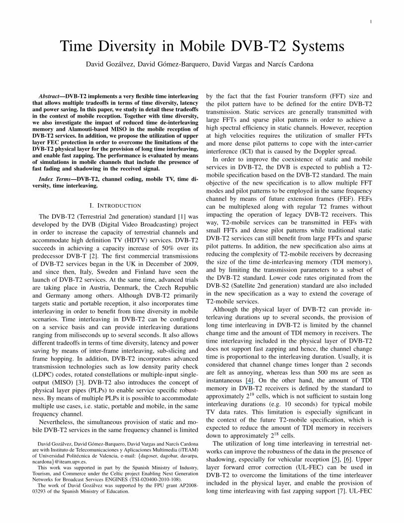
Fig. 1. Maximum PLP data rate supported in DVB-T2 with respect to theinterleaving duration for different constellations and code rates.
to adjust the LDPC code to the amount of L1-post informationto be transmitted. The codewords containing the L1 signallinginformation are uniformly distributed over all the P2 symbolsof one T2 frame in order to maximize the time diversity.Nevertheless, this accounts for an interleaving duration of justseveral miliseconds, which may not be sufficient in mobilescenarios.
III. TIME INTERLEAVING IN DVB-T2
A. Data Path
The time interleaver in DVB-T2 consists on a block in-terleaver that operates on sets of cells referred to as timeinterleaving blocks (TI blocks). Each TI block correspondsto a different utilization of the TDI memory and is interleavedas a whole by the block interleaver. Since only one TI blockis interleaved at a time by the time interleaver, no timeinterleaving exists between different TI blocks. As a result, theinterleaving duration provided by time interleaving in DVB-T2is equal to the period of time that passes from the transmissionof the first and last OFDM symbol carrying cells from the sameTI block. Due to the fact that time interleaving in DVB-T2 isperformed on a PLP basis, the maximum interleaving durationis limited by the data rate of the PLP and the amount of TDImemory available in receivers. Since the time interleaver islocated after the FEC encoder and operates with cells insteadof bits, the interleaving duration also depends on the code rateand the constellation. The maximum interleaving duration inDVB-T2 can be computed as:
Tintmax≈ TDI × CR× log2 µ
Rb, (1)
where TDI is the amount of TDI memory, CR is the coderate, µ is the number of symbols in the constellation (e.g., 4for QPSK), and Rb is the PLP data rate (in bps). The avail-able memory in DVB-T2 receivers for time de-interleavingpurposes has been set by the standard to approximately 219
cells as a compromise between interleaving capabilities andmemory size [1]. In Fig. 1, it is shown the maximum PLP datarate that is supported in DVB-T2 for different combinations of
4
FEC
Block
Interleaving Frame
TI
Block
TI
Block
TI
Block
Time
Interleaver
FEC
Block
FEC
Block
FEC
Block...
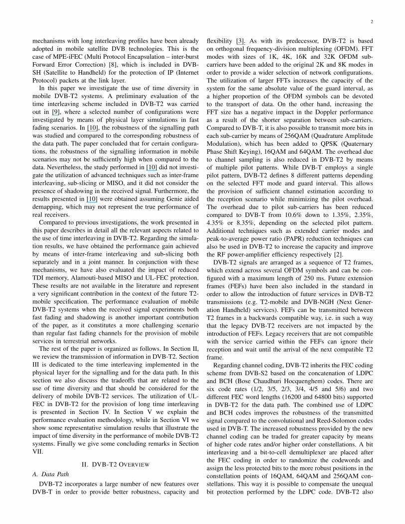
Fig. 2. Time interleaving in DVB-T2. In the figure, one interleaving frameis partitioned into three TI blocks.
constellations and code rates. As can be seen in the figure, longinterleaving durations (e.g. 10 seconds) cannot be achieved fortypical mobile TV data rates. It should be noted that in the caseof T2-mobile, the TDI memory is limited to approximately 218
cells and hence, the maximum supported PLP data rate shownin Fig. 1 would be halved for any given interleaving duration.
The PLP data rate is determined in a major way by the PLPinput mode. The utilization of input mode B divides the overalldata rate among different PLPs. This way, each PLP ends upwith a lower individual data rate and can be transmitted witha longer interleaving duration. On the contrary, input mode Acollects the entire data rate in a single PLP, which decreasesthe maximum interleaving duration that can be applied.
The FEC blocks pertaining to the same PLP are grouped ininterleaving frames before being passed to the time interleaver.Each interleaving frame consists of a dynamically varyingnumber of FEC blocks. Once the interleaving frames havebeen processed by the time interleaver, they are mapped toT2 frames for transmission. Depending on the PLP data rate,the amount of data in one T2 frame may exceed the availableTDI memory. In this case, the interleaving frame cannot be de-interleaved as a whole, and it must be partitioned in multiple TIblocks so that each TI block can be processed separately by thetime de-interleaver. This allows the transmission of PLPs witha higher data rate, but decreases the maximum interleavingduration as a result. The partition of the interleaving framesin multiple TI blocks is common in the case of input mode A,due to the transmission of a single higher data rate PLP. Thearrangement of FEC blocks for time interleaving is illustratedin Fig. 2. In this case, one interleaving frame is partitionedinto three different TI blocks that are interleaved by the timeinterleaver one after the other.
DVB-T2 allows inter-frame interleaving, frame hoppingand sub-slicing when mapping the interleaving frames to theT2 frames. Inter-frame interleaving is achieved when one
PLP 1 PLP 1 PLP 1
PLP 1 PLP 1
PLP 1
T2 Frame (≤ 250 ms) T2 Frame (≤ 250 ms) T2 Frame (≤ 250 ms)
Interleaving Frame Interleaving Frame
Interleaving Frame
T2 Frame (≤ 250 ms) T2 Frame (≤ 250 ms) T2 Frame (≤ 250 ms)
T2 Frame (≤ 250 ms) T2 Frame (≤ 250 ms) T2 Frame (≤ 250 ms)
Interleaving Frame Interleaving FrameInterleaving Frame
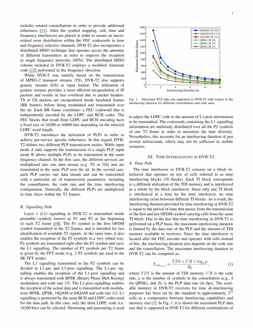
Fig. 3. Frame mapping options in DVB-T2: inter-frame interleaving (top),frame hopping (center) and sub-slicing (bottom).
interleaving frame is transmitted across multiple T2 frames.This is only allowed when the interleaving frame has beeninterleaved as a single TI block. By means of inter-frameinterleaving it is possible to extend the interleaving durationbeyond one T2 frame. It must be noted that the maximuminterleaving duration is always limited by (1). An example ofinter-frame interleaving is illustrated in Fig. 3 (top), whereone interleaving frame is mapped to be transmitted in threeT2 frames.
PLPs configured to perform frame hopping are not transmit-ted in every T2 frame but only in a subset of frames regularlydistributed over time. The separation between frames carryinginformation from one PLP is referred to as the frame interval.A frame interval of two T2 frames is represented in Fig. 3(centre).
DVB-T2 distinguishes between two different types of PLPsaccording to the number of time slices per frame. While PLPstype 1 are always carried in a single time slice per frame, thePLPs type 2 can be carried in multiples sub-slices. The lattercase is known as sub-slicing. Inside the T2 frames, the PLPstype 1 are transmitted prior to the transmission of the PLPstype 2. Although the number of sub-slices per T2 frame isconfigurable, it is the same for every PLP type 2 carried inthe same set of frames. If the number of sub-slices is highenough, the information from each PLP type 2 is transmittedcontinuously over time within the frames. Only certain valuesof sub-slicing and combinations with inter-frame interleavingare allowed in the standard. This is due to signalling issuesand undesirable interactions with the frequency interleaver thatmay result in the loss of frequency diversity [2]. It shouldbe noted that the maximum number of allowed sub-slicesdecreases with higher values of inter-frame interleaving. Thetransmission of three sub-slices per T2 frame is illustrated inFig. 3 (bottom).
5
B. Signalling Path
The L1 signalling transmitted in the P2 symbols doesnot feature time interleaving, and the interleaving durationis restricted to several miliseconds. DVB-T2 includes twomechanisms for increasing the robustness of the L1 signallingknown as L1 repetition and in-band signalling. The formerincreases the robustness of the L1 signalling by transmittingin each T2 frame the signalling information that correspondsto the current and the next T2 frame. The latter transmits theL1 signalling embedded in the data path so that it possessesthe same robustness as the data. In particular, when in-bandsignalling is used, the first BB frame of each interleaving framecarries the L1 signalling corresponding to the next interleavingframe. This way it is possible to improve the continuousreception of the service without the need of receiving the P2symbols. Although the utilization of L1 repetition and in-bandsignalling introduces a delay in transmission of one T2 frameand one interleaving frame respectively, it does not result inan increase of the channel change time.
C. Time Diversity – Latency Tradeoff
The time interleaver included in DVB-T2 does not sup-port fast zapping, and short channel change times cannot beachieved with long time interleaving. When switching to anew PLP, DVB-T2 receivers have to wait until the completereception of one entire TI block before they can de-interleaveand process the FEC blocks. Consequently, the channel changetime is proportional to the interleaving duration. The longerthe interleaving duration, the longer the receivers must waitprior to the de-interleaving of the TI blocks.
In the case of PLPs type 1, all the cells are transmittedcontiguously in one single time-slice within the T2 frames.As a result, the intra-frame interleaving duration is limited bythe maximum number of cells that fit in the TDI memory. Inthe case of 219 cells, this corresponds to approximately 100ms. On the contrary, PLPs type 2 employ sub-slicing to spreadthe cells across the T2 frame and in this case, the interleavingduration is limited by the T2 frame length (up to 250 ms).
Inter-frame interleaving can be used with PLPs type 1 andPLPs type 2 to extend the interleaving depth beyond theduration of one T2 frame. By means of inter-frame interleavingit is possible to achieve interleaving durations up to severalseconds at the expense of increased channel change time.
Frame hopping on the other hand increases the channelchange time as it delays the transmission of informationbetween non-consecutive T2 frames. In addition, it may resultin an improvement of the intra-frame interleaving. When framehopping is used, the information from the PLPs must bebuffered during one frame interval before it can transmittedover the air. This increases the amount of information to betransmitted in one T2 frame, which results in a higher TDImemory utilization and longer interleaving durations whensub-slicing is not employed.
Assuming that sub-slicing is used, the average channelchange time that a receiver must wait until the completereception of the first interleaving frame can be computed as:
1 2 3 4 5 6 7 8 9 100
2
4
6
8
10
12
14
16
Inter−Frame Interleaving
Ave
rage
Cha
nnel
Cha
nge
Tim
e (s
)
FI=4 Tf=250msFI=3 Tf=250msFI=2 Tf=250msFI=1 Tf=250msFI=4 Tf=50msFI=3 Tf=50msFI=2 Tf=50msFI=1 Tf=50ms
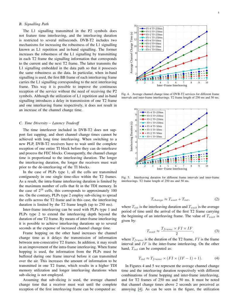
Fig. 4. Average channel change time of DVB-T2 services for different frameintervals and inter-frame interleavings. T2 frame length of 250 ms and 50 ms.
1 2 3 4 5 6 7 8 9 100
1
2
3
4
5
6
7
8
9
10
Inter−Frame Interleaving
Inte
rleav
ing
Dur
atio
n (s
)
FI=4 Tf=250msFI=3 Tf=250msFI=2 Tf=250msFI=1 Tf=250msFI=4 Tf=50msFI=3 Tf=50msFI=2 Tf=50msFI=1 Tf=50ms
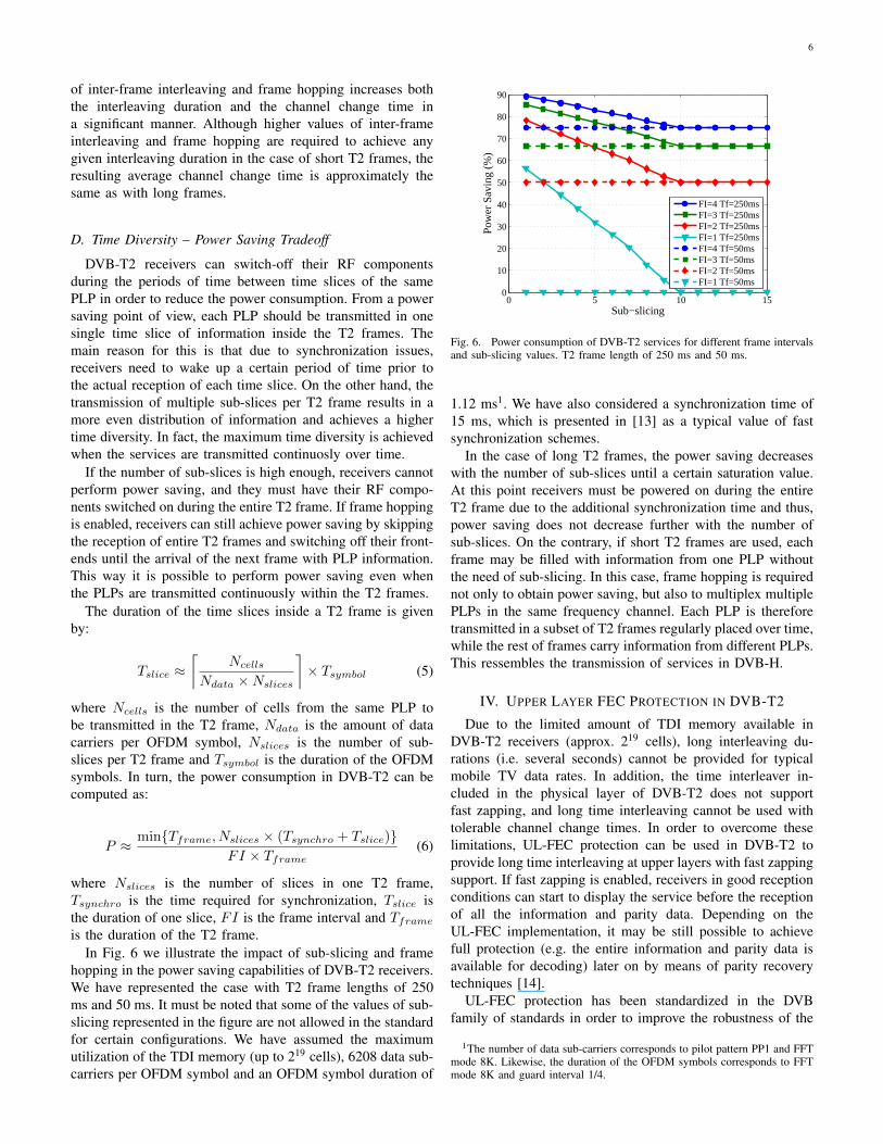
Fig. 5. Interleaving duration for different frame intervals and inter-frameinterleavings. T2 frame length of 250 ms and 50 ms.
Tchange ≈ Twait + Tint, (2)
where Tint is the interleaving duration and Twait is the averageperiod of time until the arrival of the first T2 frame carryingthe beginning of an interleaving frame. The value of Twait isgiven by:
Twait ≈Tframe × FI × IF
2, (3)
where Tframe is the duration of the T2 frame, FI is the frameinterval and IF is the inter-frame interleaving. On the otherhand, Tint can be computed as:
Tint ≈ Tframe × (FI × (IF − 1) + 1). (4)
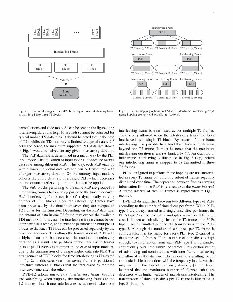
In Figures 4 and 5 we represent the average channel changetime and the interleaving duration respectively with differentcombinations of frame hopping and inter-frame interleaving,and for T2 frames of 250 ms and 50 ms. It must be notedthat channel change times above 2 seconds are perceived asannoying [4]. As can be seen in the figure, the utilization
6
of inter-frame interleaving and frame hopping increases boththe interleaving duration and the channel change time ina significant manner. Although higher values of inter-frameinterleaving and frame hopping are required to achieve anygiven interleaving duration in the case of short T2 frames, theresulting average channel change time is approximately thesame as with long frames.
D. Time Diversity – Power Saving Tradeoff
DVB-T2 receivers can switch-off their RF componentsduring the periods of time between time slices of the samePLP in order to reduce the power consumption. From a powersaving point of view, each PLP should be transmitted in onesingle time slice of information inside the T2 frames. Themain reason for this is that due to synchronization issues,receivers need to wake up a certain period of time prior tothe actual reception of each time slice. On the other hand, thetransmission of multiple sub-slices per T2 frame results in amore even distribution of information and achieves a highertime diversity. In fact, the maximum time diversity is achievedwhen the services are transmitted continuosly over time.
If the number of sub-slices is high enough, receivers cannotperform power saving, and they must have their RF compo-nents switched on during the entire T2 frame. If frame hoppingis enabled, receivers can still achieve power saving by skippingthe reception of entire T2 frames and switching off their front-ends until the arrival of the next frame with PLP information.This way it is possible to perform power saving even whenthe PLPs are transmitted continuously within the T2 frames.
The duration of the time slices inside a T2 frame is givenby:
Tslice ≈⌈
Ncells
Ndata ×Nslices
⌉× Tsymbol (5)
where Ncells is the number of cells from the same PLP tobe transmitted in the T2 frame, Ndata is the amount of datacarriers per OFDM symbol, Nslices is the number of sub-slices per T2 frame and Tsymbol is the duration of the OFDMsymbols. In turn, the power consumption in DVB-T2 can becomputed as:
P ≈ min{Tframe, Nslices × (Tsynchro + Tslice)}FI × Tframe
(6)
where Nslices is the number of slices in one T2 frame,Tsynchro is the time required for synchronization, Tslice isthe duration of one slice, FI is the frame interval and Tframe
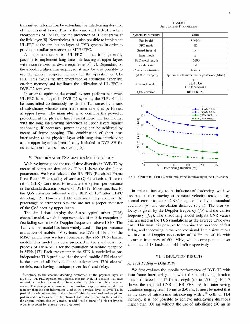
is the duration of the T2 frame.In Fig. 6 we illustrate the impact of sub-slicing and frame
hopping in the power saving capabilities of DVB-T2 receivers.We have represented the case with T2 frame lengths of 250ms and 50 ms. It must be noted that some of the values of sub-slicing represented in the figure are not allowed in the standardfor certain configurations. We have assumed the maximumutilization of the TDI memory (up to 219 cells), 6208 data sub-carriers per OFDM symbol and an OFDM symbol duration of
0 5 10 150
10
20
30
40
50
60
70
80
90
Sub−slicing
Pow
er S
avin
g (%
)
FI=4 Tf=250msFI=3 Tf=250msFI=2 Tf=250msFI=1 Tf=250msFI=4 Tf=50msFI=3 Tf=50msFI=2 Tf=50msFI=1 Tf=50ms
Fig. 6. Power consumption of DVB-T2 services for different frame intervalsand sub-slicing values. T2 frame length of 250 ms and 50 ms.
1.12 ms1. We have also considered a synchronization time of15 ms, which is presented in [13] as a typical value of fastsynchronization schemes.
In the case of long T2 frames, the power saving decreaseswith the number of sub-slices until a certain saturation value.At this point receivers must be powered on during the entireT2 frame due to the additional synchronization time and thus,power saving does not decrease further with the number ofsub-slices. On the contrary, if short T2 frames are used, eachframe may be filled with information from one PLP withoutthe need of sub-slicing. In this case, frame hopping is requirednot only to obtain power saving, but also to multiplex multiplePLPs in the same frequency channel. Each PLP is thereforetransmitted in a subset of T2 frames regularly placed over time,while the rest of frames carry information from different PLPs.This ressembles the transmission of services in DVB-H.
IV. UPPER LAYER FEC PROTECTION IN DVB-T2
Due to the limited amount of TDI memory available inDVB-T2 receivers (approx. 219 cells), long interleaving du-rations (i.e. several seconds) cannot be provided for typicalmobile TV data rates. In addition, the time interleaver in-cluded in the physical layer of DVB-T2 does not supportfast zapping, and long time interleaving cannot be used withtolerable channel change times. In order to overcome theselimitations, UL-FEC protection can be used in DVB-T2 toprovide long time interleaving at upper layers with fast zappingsupport. If fast zapping is enabled, receivers in good receptionconditions can start to display the service before the receptionof all the information and parity data. Depending on theUL-FEC implementation, it may be still possible to achievefull protection (e.g. the entire information and parity data isavailable for decoding) later on by means of parity recoverytechniques [14].
UL-FEC protection has been standardized in the DVBfamily of standards in order to improve the robustness of the
1The number of data sub-carriers corresponds to pilot pattern PP1 and FFTmode 8K. Likewise, the duration of the OFDM symbols corresponds to FFTmode 8K and guard interval 1/4.
7
transmitted information by extending the interleaving durationof the physical layer. This is the case of DVB-SH, whichincorporates MPE-iFEC for the protection of IP datagrams atthe link layer [8]. Nevertheless, it is also possible to implementUL-FEC at the application layer of DVB systems in order toprovide a similar protection as MPE-iFEC.
A major motivation for UL-FEC is that it is generallypossible to implement long time interleaving at upper layerswith more relaxed hardware requirements2 [7]. Depending onthe encoding algorithm employed, it may be also possible touse the general purpose memory for the operation of UL-FEC. This avoids the implementation of additional expensiveon-chip memory and facilitates the utilization of UL-FEC inDVB-T2 receivers.
In order to optimize the overall system performance whenUL-FEC is employed in DVB-T2 systems, the PLPs shouldbe transmitted continuously inside the T2 frames by meansof sub-slicing whereas inter-frame interleaving is performedat upper layers. The main idea is to combine the powerfulprotection at the physical layer against noise and fast fading,with the long interleaving protection at upper layers againstshadowing. If necessary, power saving can be achieved bymeans of frame hopping. The combination of short timeinterleaving at the physical layer with long time interleavingat the upper layer has been already included in DVB-SH forits utilization in class 1 receivers [15].
V. PERFORMANCE EVALUATION METHODOLOGY
We have investigated the use of time diversity in DVB-T2 bymeans of computer simulations. Table I shows the simulationparameters. We have selected the BB FER (Baseband FrameError Rate) 1% as quality of service (QoS) criterion. Bit errorratios (BER) were used to evaluate the system performancein the standardization process of DVB-T2. More specifically,the QoS criterion followed was a BER of 10-7 after LDPCdecoding [2]. However, BER criterions only indicate thepercentage of erroneous bits and are not a proper indicatorof the QoS seen by upper layers.
The simulations employ the 6-taps typical urban (TU6)channel model, which is representative of mobile reception infast fading scenarios for Doppler frequencies above 10 Hz. TheTU6 channel model has been widely used in the performanceevaluation of mobile TV systems like DVB-H [16]. For theMISO simulations we have considered the SFN TU6 channelmodel. This model has been proposed in the standardizationprocess of DVB-NGH for the evaluation of mobile receptionin SFNs [17]. Each transmitter in the SFN is modelled as oneindependent TU6 profile so that the total mobile SFN channelis the sum of all individual and independent TU6 channelmodels, each having a unique power level and delay.
2Contrary to the channel decoding performed at the physical layer ofDVB-T2, UL-FEC operates on a packet erasure level. This means that eachtransmitted packet is considered in reception as either entirely correct orerased. The storage of erasure error information requires considerable lessmemory than the soft information used in the physical layer of DVB-T2. Inparticular, each cell requires in the order of 10 bits for each real and imaginarypart in addition to some bits for channel state information. On the contrary,the erasure information only needs an additional storage of 1 bit per byte inorder to account for erasures on a byte level.
TABLE ISIMULATION PARAMETERS
System Parameters Value
Bandwidth 8 MHz
FFT mode 8K
Guard Interval 1/4
Input mode B
FEC word length 16200
Code Rate 1/2
Channel estimation Perfect
QAM demapping Optimum soft maximum a posteriori (MAP)
TU6SFN TU6Channel model
TU6+shadowing
QoS criterion BB FER 1%
0 50 100 150 200 2502
4
6
8
10
12
14
Interleaving Duration (ms)
CN
R a
t BB
FE
R 1
% (
dB)
16QAM 10Hz16QAM 80HzQPSK 10HzQPSK 80Hz
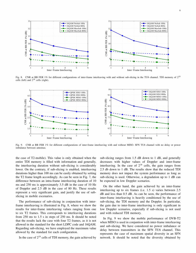
Fig. 7. CNR at BB FER 1% with intra-frame interleaving in the TU6 channel.
In order to investigate the influence of shadowing, we haveassumed a user moving at constant velocity across a log-normal carrier-to-noise (CNR) map defined by its standarddeviation (σ) and correlation distance (dcorr). The user ve-locity is given by the Doppler frequency (fd) and the carrierfrequency (frf ). The shadowing model outputs CNR valuesthat are used in the TU6 simulations as the average CNR overtime. This way it is possible to combine the presence of fastfading and shadowing in the received signal. In the simulationswe have used Doppler frequencies of 10 Hz and 80 Hz witha carrier frequency of 600 MHz, which correspond to uservelocities of 18 km/h and 144 km/h respectively.
VI. SIMULATION RESULTS
A. Fast Fading – Data Path
We first evaluate the mobile performance of DVB-T2 withintra-frame interleaving, i.e. when the interleaving durationdoes not exceed the T2 frame length (up to 250 ms). Fig. 7shows the required CNR at BB FER 1% for interleavingdurations ranging from 10 ms to 250 ms. It must be noted thatin the case of intra-frame interleaving with 219 cells of TDImemory, it is not possible to achieve interleaving durationshigher than 100 ms without the use of sub-slicing (50 ms in
8
1 2 3 4 5 67
8
9
10
11
12
13
Inter−Frame Interleaving
CN
R a
t BB
FE
R 1
% (
dB)
16QAM NoSub 10Hz16QAM NoSub 80Hz16QAM MaxSub 10Hz16QAM MaxSub 80Hz
1 2 3 4 5 67
8
9
10
11
12
13
Inter−Frame Interleaving
CN
R a
t BB
FE
R 1
% (
dB)
16QAM NoSub 10Hz16QAM NoSub 80Hz16QAM MaxSub 10Hz16QAM MaxSub 80Hz
Fig. 8. CNR at BB FER 1% for different configurations of inter-frame interleaving with and without sub-slicing in the TU6 channel. TDI memory of 219
cells (left) and 218 cells (right).
1 2 3 4 5 61
1.5
2
2.5
3
3.5
4
4.5
5
Inter−Frame Interleaving
CN
R a
t BB
FE
R 1
% (
dB)
QPSK SISO 10HzQPSK SISO 80HzQPSK MISO 10HzQPSK MISO 80Hz
1 2 3 4 5 66
6.5
7
7.5
8
8.5
9
9.5
10
Inter−Frame Interleaving
CN
R a
t BB
FE
R 1
% (
dB)
16QAM SISO 10Hz16QAM SISO 80Hz16QAM MISO 10Hz16QAM MISO 80Hz
Fig. 9. CNR at BB FER 1% for different configurations of inter-frame interleaving with and without MISO. SFN TU6 channel with no delay or powerimbalance between antennas.
the case of T2-mobile). This value is only obtained when theentire TDI memory is filled with information and generally,the interleaving duration without sub-slicing is considerablylower. On the contrary, if sub-slicing is enabled, interleavingdurations higher than 100 ms can be easily obtained by settingthe T2 frame length accordingly. As can be seen in Fig. 7, thedifference between an intra-frame interleaving duration of 10ms and 250 ms is approximately 3.5 dB in the case of 10 Hzof Doppler and 2.5 dB in the case of 80 Hz. These resultsrepresent a very significant gain, and justify the use of sub-slicing in mobile escenarios.
The performance of sub-slicing in conjunction with inter-frame interleaving is illustrated in Fig. 8, where we show theresults for inter-frame interleaving values ranging from oneto six T2 frames. This corresponds to interleaving durationsfrom 250 ms to 1.5 s in steps of 250 ms. It should be notedthat the results lack the case with four T2 frames, as it is notallowed in the standard for the short LDPC code and 16QAM.Regarding sub-slicing, we have employed the maximum valueallowed by the standard for each configuration.
In the case of 219 cells of TDI memory, the gain achieved by
sub-slicing ranges from 1.5 dB down to 1 dB, and generallydecreases with higher values of Doppler and inter-frameinterleaving. In the case of 218 cells, the gain ranges from2.5 db down to 1 dB. The results show that the reduced TDImemory does not impact the system performance as long assub-slicing is used. Otherwise, a degradation up to 1 dB canbe expected in low Doppler scenarios.
On the other hand, the gain achieved by an inter-frameinterleaving up to six frames (i.e. 1.5 s) varies between 2.5dB and less than 0.5 dB. As can be seen, the performance ofinter-frame interleaving is heavily conditioned by the use ofsub-slicing, the TDI memory and the Doppler. In particular,the gain due to inter-frame interleaving is only significant inlow Doppler scenarios, especially if sub-slicing is not usedand with reduced TDI memory.
In Fig. 9 we show the mobile performance of DVB-T2when MISO is used in conjuntion with inter-frame interleavingand sub-slicing. We have considered no power imbalance ordelay between transmitters in the SFN TU6 channel. Thisrepresents the case of maximum spatial diversity in an SFNnetwork. It should be noted that the diversity obtained by
9
−5 0 5 10 15 20 2510
−3
10−2
10−1
100
CNR (dB)
Fra
me
Err
or R
ate
64QAM64QAM Rep.16QAM 16QAM Rep.QPSKQPSK Rep.BPSKBPSK Rep.
−5 0 5 10 15 20 2510
−3
10−2
10−1
100
CNR (dB)
Fra
me
Err
or R
ate
64QAM64 QAM Rep.16QAM16QAM Rep.QPSKQPSK Rep.BPSKBPSK Rep.
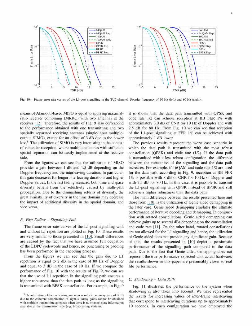
Fig. 10. Frame error rate curves of the L1-post signalling in the TU6 channel. Doppler frequency of 10 Hz (left) and 80 Hz (right).
means of Alamouti-based MISO is equal to applying maximal-ratio receiver combining (MRRC) with two antennas at thereceiver [12]. Therefore, the results of Fig. 9 also correspondto the performance obtained with one transmitting and twospatially separated receiving antennas (single-input multiple-output, SIMO), except for an offset of 3 dB due to the powerloss3. The utilization of SIMO is very interesting in the contextof vehicular reception, where multiple antennas with sufficientspatial separation can be easily implemented at the receiverside.
From the figures we can see that the utilization of MISOprovides a gain between 1 dB and 1.5 dB depending on theDoppler frequency and the interleaving duration. In particular,this gain decreases for longer interleaving durations and higherDoppler values. In the fast fading scenario, both time and spacediversity benefit from the selectivity caused by multi-pathpropagation. Due to the diminishing returns of diversity, thegreat availability of diversity in the time domain may decreasethe impact of additional diversity in the spatial domain, andvice versa.
B. Fast Fading – Signalling Path
The frame error rate curves of the L1-post signalling withand without L1 repetition are plotted in Fig. 10. These resultsare very similar to those presented in [10]. Small differencesare caused by the fact that we have assumed full ocupationof the LDPC codewords and hence, no puncturing or paddinghas been performed in the encoding process.
From the figures we can see that the gain due to L1repetition is equal to 2 dB in the case of 80 Hz of Dopplerand equal to 3 dB in the case of 10 Hz. If we compare theperformance of Fig. 10 with the results of Fig. 9, we can seethat the use of L1 repetition in the signalling path ensures ahigher robustness than the data path as long as the signallingis transmitted with BPSK constellation. For example, in Fig. 9
3The utilization of two receiving antennas results in an array gain of 3 dBdue to the coherent combination of signals. Array gains cannot be obtainedwith multiple transmitting antennas when there is no channel state informationavailable at the transmission side (e.g. broadcasting systems)
it is shown that the data path transmitted with QPSK andcode rate 1/2 can achieve reception at BB FER 1% withapproximately 3.0 dB of CNR for 10 Hz of Doppler and with2.5 dB for 80 Hz. From Fig. 10 we can see that receptionof the L1-post signalling at FER 1% can be achieved withapproximately 1 dB lower.
The previous results represent the worst case scenario inwhich the data path is transmitted with the most robustconstellation (QPSK) and code rate (1/2). If the data pathis transmitted with a less robust configuration, the differencebetween the robustness of the signalling and the data pathincreases. For example, if 16QAM and code rate 1/2 are usedfor the data path, according to Fig. 9, reception at BB FER1% is possible with 8 dB of CNR for 10 Hz of Doppler andwith 7.5 dB for 80 Hz. In this case, it is possible to transmitthe L1-post signalling with QPSK instead of BPSK and stillachieve a higher robustness than the data path.
The main difference between the results presented here andthose from [10], is the utilization of Genie aided demapping inthe later case. Genie aided demapping emulates the ultimateperformance of iterative decoding and demapping. In conjunc-tion with rotated constellations, Genie aided demapping canachieve gains up to several dBs depending on the constellationand code rate [11]. On the other hand, rotated constellationsare not allowed for the L1 signalling and hence, the utilizationof Genie aided does not provide any significant gain. Becauseof this, the results presented in [10] depict a pessimisticperformance of the signalling path compared to the datapath. Due to the fact that Genie aided demapping does notrepresent the true performance expected with actual hardware,the results shown in this paper are presumably closer to reallife performance.
C. Shadowing – Data Path
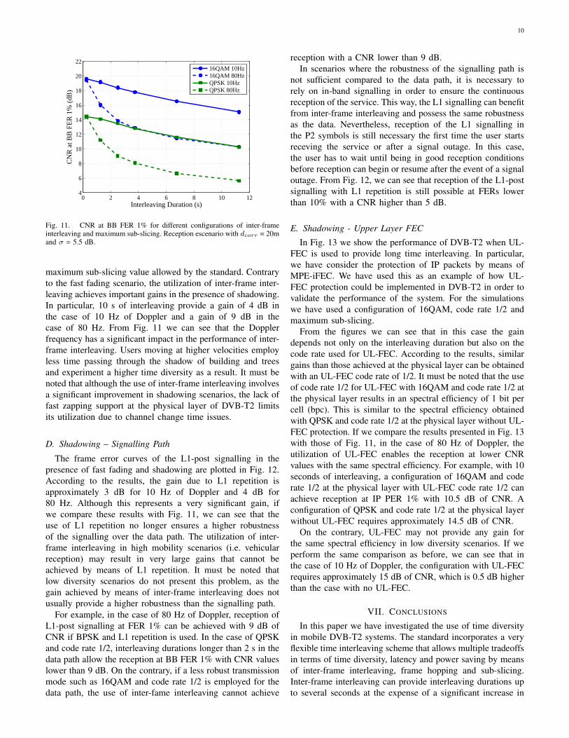
Fig. 11 illustrates the performance of the system whenshadowing is also taken into account. We have representedthe results for increasing values of inter-frame interleavingthat correspond to interleaving durations up to approximately10 seconds. In each configuration we have employed the
10
0 2 4 6 8 10 124
6
8
10
12
14
16
18
20
22
Interleaving Duration (s)
CN
R a
t BB
FE
R 1
% (
dB)
16QAM 10Hz16QAM 80HzQPSK 10HzQPSK 80Hz
Fig. 11. CNR at BB FER 1% for different configurations of inter-frameinterleaving and maximum sub-slicing. Reception escenario with dcorr = 20mand σ = 5.5 dB.
maximum sub-slicing value allowed by the standard. Contraryto the fast fading scenario, the utilization of inter-frame inter-leaving achieves important gains in the presence of shadowing.In particular, 10 s of interleaving provide a gain of 4 dB inthe case of 10 Hz of Doppler and a gain of 9 dB in thecase of 80 Hz. From Fig. 11 we can see that the Dopplerfrequency has a significant impact in the performance of inter-frame interleaving. Users moving at higher velocities employless time passing through the shadow of building and treesand experiment a higher time diversity as a result. It must benoted that although the use of inter-frame interleaving involvesa significant improvement in shadowing scenarios, the lack offast zapping support at the physical layer of DVB-T2 limitsits utilization due to channel change time issues.
D. Shadowing – Signalling Path
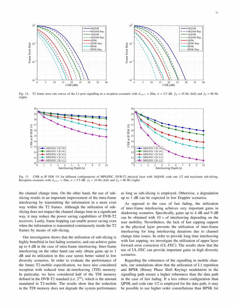
The frame error curves of the L1-post signalling in thepresence of fast fading and shadowing are plotted in Fig. 12.According to the results, the gain due to L1 repetition isapproximately 3 dB for 10 Hz of Doppler and 4 dB for80 Hz. Although this represents a very significant gain, ifwe compare these results with Fig. 11, we can see that theuse of L1 repetition no longer ensures a higher robustnessof the signalling over the data path. The utilization of inter-frame interleaving in high mobility scenarios (i.e. vehicularreception) may result in very large gains that cannot beachieved by means of L1 repetition. It must be noted thatlow diversity scenarios do not present this problem, as thegain achieved by means of inter-frame interleaving does notusually provide a higher robustness than the signalling path.
For example, in the case of 80 Hz of Doppler, reception ofL1-post signalling at FER 1% can be achieved with 9 dB ofCNR if BPSK and L1 repetition is used. In the case of QPSKand code rate 1/2, interleaving durations longer than 2 s in thedata path allow the reception at BB FER 1% with CNR valueslower than 9 dB. On the contrary, if a less robust transmissionmode such as 16QAM and code rate 1/2 is employed for thedata path, the use of inter-fame interleaving cannot achieve
reception with a CNR lower than 9 dB.In scenarios where the robustness of the signalling path is
not sufficient compared to the data path, it is necessary torely on in-band signalling in order to ensure the continuousreception of the service. This way, the L1 signalling can benefitfrom inter-frame interleaving and possess the same robustnessas the data. Nevertheless, reception of the L1 signalling inthe P2 symbols is still necessary the first time the user startsreceving the service or after a signal outage. In this case,the user has to wait until being in good reception conditionsbefore reception can begin or resume after the event of a signaloutage. From Fig. 12, we can see that reception of the L1-postsignalling with L1 repetition is still possible at FERs lowerthan 10% with a CNR higher than 5 dB.
E. Shadowing - Upper Layer FEC
In Fig. 13 we show the performance of DVB-T2 when UL-FEC is used to provide long time interleaving. In particular,we have consider the protection of IP packets by means ofMPE-iFEC. We have used this as an example of how UL-FEC protection could be implemented in DVB-T2 in order tovalidate the performance of the system. For the simulationswe have used a configuration of 16QAM, code rate 1/2 andmaximum sub-slicing.
From the figures we can see that in this case the gaindepends not only on the interleaving duration but also on thecode rate used for UL-FEC. According to the results, similargains than those achieved at the physical layer can be obtainedwith an UL-FEC code rate of 1/2. It must be noted that the useof code rate 1/2 for UL-FEC with 16QAM and code rate 1/2 atthe physical layer results in an spectral efficiency of 1 bit percell (bpc). This is similar to the spectral efficiency obtainedwith QPSK and code rate 1/2 at the physical layer without UL-FEC protection. If we compare the results presented in Fig. 13with those of Fig. 11, in the case of 80 Hz of Doppler, theutilization of UL-FEC enables the reception at lower CNRvalues with the same spectral efficiency. For example, with 10seconds of interleaving, a configuration of 16QAM and coderate 1/2 at the physical layer with UL-FEC code rate 1/2 canachieve reception at IP PER 1% with 10.5 dB of CNR. Aconfiguration of QPSK and code rate 1/2 at the physical layerwithout UL-FEC requires approximately 14.5 dB of CNR.
On the contrary, UL-FEC may not provide any gain forthe same spectral efficiency in low diversity scenarios. If weperform the same comparison as before, we can see that inthe case of 10 Hz of Doppler, the configuration with UL-FECrequires approximately 15 dB of CNR, which is 0.5 dB higherthan the case with no UL-FEC.
VII. CONCLUSIONS
In this paper we have investigated the use of time diversityin mobile DVB-T2 systems. The standard incorporates a veryflexible time interleaving scheme that allows multiple tradeoffsin terms of time diversity, latency and power saving by meansof inter-frame interleaving, frame hopping and sub-slicing.Inter-frame interleaving can provide interleaving durations upto several seconds at the expense of a significant increase in
11
0 5 10 15 20 25 30 35 4010
−3
10−2
10−1
100
CNR (dB)
Fra
me
Err
or R
ate
64QAM64QAM Rep.16QAM16QAM Rep.QPSKQPSK Rep.BPSKBPSK Rep.
0 5 10 15 20 25 30 35 4010
−3
10−2
10−1
100
CNR (dB)
Fra
me
Err
or R
ate
64QAM64QAM Rep.16QAM16QAM Rep.QPSKQPSK Rep.BPSKBPSK Rep.
Fig. 12. T2 frame error rate curves of the L1-post signalling in a reception escenario with dcorr = 20m, σ = 5.5 dB, fd = 10 Hz (left) and fd = 80 Hz(right).
0 1 2 3 4 5 6 7 8 9 1010
11
12
13
14
15
16
17
18
19
20
Interleaving Depth (s)
CN
R a
t IP
PER
1%
MPEiFEC CR 7/8MPEiFEC CR 5/6MPEiFEC CR 3/4MPEiFEC CR 2/3MPEiFEC CR 1/2
0 1 2 3 4 5 6 7 8 9 1010
11
12
13
14
15
16
17
18
19
20
Interleaving Depth (s)
CN
R a
t IP
PER
1%
MPEiFEC CR 7/8MPEiFEC CR 5/6MPEiFEC CR 3/4MPEiFEC CR 2/3MPEiFEC CR 1/2
Fig. 13. CNR at IP FER 1% for different configurations of MPEiFEC. DVB-T2 physical layer with 16QAM, code rate 1/2 and maximum sub-slicing.Reception escenario with dcorr = 20m, σ = 5.5 dB, fd = 10 Hz (left) and fd = 80 Hz (right).
the channel change time. On the other hand, the use of sub-slicing results in an important improvement of the intra-frameinterleaving by transmitting the information in a more evenway within the T2 frames. Although the utilization of sub-slicing does not impact the channel change time in a significantway, it may reduce the power saving capabilities of DVB-T2receivers. Lastly, frame hopping can enable power saving evenwhen the information is transmitted continuously inside the T2frames by means of sub-slicing.
Our investigation shows that the utilization of sub-slicing ishighly benefitial in fast fading scenarios, and can achieve gainsup to 4 dB in the case of intra-frame interleaving. Inter-frameinterleaving on the other hand can only obtain gains up to 1dB and its utilization in this case seems better suited to lowdiversity scenarios. In order to evaluate the performance ofthe future T2-mobile especification, we have also consideredreception with reduced time de-interleaving (TDI) memory.In particular, we have considered half of the TDI memorydefined in the DVB-T2 standard (i.e. 218), which is the amountmandated in T2-mobile. The results show that the reductionin the TDI memory does not degrade the system performance
as long as sub-slicing is employed. Otherwise, a degradationup to 1 dB can be expected in low Doppler scenarios.
As opposed to the case of fast fading, the utilizationof inter-frame interleaving achieves very important gains inshadowing scenarios. Specifically, gains up to 4 dB and 9 dBcan be obtained with 10 s of interleaving depending on theuser mobility. Nevertheless, the lack of fast zapping supportat the physical layer prevents the utilization of inter-frameinterleaving for long interleaving durations due to channelchange time issues. In order to provide long time interleavingwith fast zapping, we investigate the utilization of upper layerforward error correction (UL-FEC). The results show that theuse of UL-FEC can provide important gains in high diversityscenarios.
Regarding the robustness of the signalling in mobile chan-nels, our simulations show that the utilization of L1 repetitionand BPSK (Binary Phase Shift Keying) modulation in thesignalling path ensure a higher robustness than the data pathin the case of fast fading. If a less robust configuration thanQPSK and code rate 1/2 is employed for the data path, it maybe possible to use higher order constellations than BPSK for
12
the signalling path and still achieve a higher robustness.On the contrary, the robustness of the L1 signalling carried
in the P2 symbols may not be sufficiently high in shadowingescenarios when compared to the data path. Due to the largegains achieved by inter-frame interleaving, the use of L1repetition may no longer ensure a higher robustness whenthe data path is transmitted with the most robust transmissionmodes. In this case, the transmission of the L1 signalling hasto rely on in-band signalling to ensure the continuous receptionof the service. Since the reception of the regular L1 signallingtransmitted in the P2 symbols is still necessary at the beginningof the reception or after a signal outage, the user does not haveother choice but to wait until being in good channel conditionsbefore it is possible to begin or resume the service.
REFERENCES
[1] Frame structure channel coding and modulation for a second generationdigital terrestrial television broadcasting system (DVB-T2), ETSI Std.EN 302 755 v1.2.1, 2011.
[2] Implementation guidelines for a second generation digital terrestrialtelevision broadcasting system (DVB-T2), ETSI Std. TR 102 831v0.10.4, 2010.
[3] L. Vangelista et al., “Key technologies for next-generation terrestrialdigital television standard DVB-T2,” IEEE Communications Magazine,vol. 47, no. 10, p. 146-153, 2009.
[4] H. Fuchs and N. Farber, “Optimizing channel change time in IPTV appli-cations,” Proc. IEEE Broadband Multimedia Systems and Broadcasting,Las Vegas, USA, Mar. 2008.
[5] D. Gozalvez, D. Gomez-Barquero and N. Cardona, “Performance eval-uation of the MPE-iFEC sliding RS encoding for DVB-H streamingservices,” Proc. IEEE Personal, Indoor and Mobile Radio Conference,Cannes, France, Sep. 2008.
[6] D. Gomez-Barquero, D. Gozalvez and N. Cardona, “Application layerFEC for mobile TV delivery in IP datacast over DVB-H systems,” IEEETransactions on Broadcasting, vol. 55, no. 2, p. 396-406, 2009.
[7] Upper Layer Forward Error Correction for DVB Systems (ULFEC),ETSI Std. TR 102 993 v1.1.1, 2011.
[8] Multi-Protocol Encapsulation – inter-burst Forward Error Correction(MPE-iFEC), ETSI Std. TS 102 772 v1.1.1, 2010.
[9] D. Gozalvez, D. Vargas, D. Gomez-Barquero and N. Cardona, “Perfor-mance evaluation of DVB-T2 time interleaving in mobile environments,”Proc. IEEE Vehicular Technology Conference, Ottawa, Canada, Sep.2010.
[10] T. Jokela, M. Tupala and J. Paavola, “Analysis of physical layer signalingtransmission in DVB-T2 systems,” IEEE Transactions on Broadcasting,vol. 56, no. 3, p. 410-417, 2010.
[11] C. Abdel Nour and C. Douillard, “Rotated QAM constellations toimprove BICM performance for DVB-T2,‘” Proc. IEEE InternationalSymposium on Spread Spectrum Techniques and Applications, Bologna,Italy, Aug. 2008.
[12] S. M. Alamouti, “A simple transmit diversity technique for wirelesscommunications,” IEEE Journal on Selected Areas in Communications,vol. 16, no. 8, pp. 1451-1458, 1998.
[13] Implementation guidelines for DVB handheld services, ETSI Std. TR102 377 v1.4.1, 2009.
[14] M. L. Alberi Morel et al., “Performance evaluation of channel changefor DVB-SH streaming services,” Proc. IEEE International Conferenceon Communications, South Africa, May 2010.
[15] Guidelines for the Implementation for Satellite Services to Handhelddevices (SH) below 3GHz, ETSI Std. TS 102 584 v1.2.1, 2011.
[16] EUREKA/CELTIC WingTV Project web site [http://projects.celticinitiative.org/WING-TV/].
[17] P. Moss, “DVB-NGH channel models,” TM-NGH063, 2010.