the impact of groundwater on the excavation of tunnels in two different hydrogeological settings in...
TRANSCRIPT
The impact of groundwater on the excavation of tunnels in two
different hydrogeological settings in central Italy
Ugo Chiocchini & Fabio Castaldi
Abstract To double the capacity of the Orte–Falconararailway line (central Italy), the Santa Croce tunnel wasconstructed (1985–1995), which runs between the NeraMontoro and Narni stations. In the same period, to doublethe capacity of the Ancona–Bari railway line, the Moro,Cintioni, S. Giovanni and Diavolo tunnels were con-structed between the Ortona and Casalbordino stations.The high likelihood of intercepting a significant volume ofgroundwater in calcareous rocks of the Santa Croce tunnelled to a shift in the layout of the tunnel, which allowedconstruction of the tunnel by more rapid and lessexpensive means. Groundwater along the Moro tunnellayout, in a sandy aquifer, has been drained by theexcavation of a preliminary tunnel, which allowed adischarge of up to 0.080m3/s. In the S. Giovanni andDiavolo tunnels, a particular hydrogeological setting wasfound to exist in the form of lens-shaped bodies of finegrey sand-and-silt aquitards intercalated between thebottom muddy-sandy deposits (very low permeability)and the sandy aquifer; this caused sudden groundwaterinflow and tunnel collapse. The S. Giovanni tunnnel,excavation was completed using the HydroShield system,whereas in the Diavolo tunnel, a well-point system wasadopted, which avoided any environmental hazards.
Keywords Italy . Groundwater management . Railwaytunnel . Aquitard . Geophsycal methods
Introduction
The presence of aquifers and aquitards of significantvolumes is one of the most important problems to beaddressed when planning and excavating tunnels for civilengineering works such as roads, railways, hydraulic pipesand mining. When a tunnel interferes with groundwater,serious problems can arise during the excavation becauseof water flow, and at the same time, water is drained,which means this resource is lost for at least theimmediate future, and possibly forever.
The following issues are relevant when groundwaterinterferes with tunnelling. First, accurate forecasting of thehydraulic head is fundamental for determining thedimensions of the definitive precastings and their long-term efficiency. Second, from the design and excavationpoint of view, the inflow of groundwater into the tunnels,especially if under high pressure, causes hazardousconditions and slowing or interruption of construction,which results in higher construction costs (Cesano et al.2000; Day 2004), puts the excavation face stability at riskand could cause a collapse of the tunnel cavity. Manage-ment of groundwater drained by tunnelling is a veryimportant long-term issue of the tunnel design and couldalso raise legal disputes with respect to the rights of water-resource use. Lowering of the piezometric levels altersgroundwater flow systems, which also affects the surfacestreams and ecosystems. Thus, the population andeconomics of a territory can suffer significant damagebecause serious problems arise when providing water forpotable supply, managing agriculture, fishing, pisciculture,farming and tourism (Sjolander-Lindqvist 2005). Thescale of the impact depends on how much the waterdrainage discharges can be reduced and/or lost from thehydrogeological system (Ii and Kagami 1997; Kitterod etal. 2000). Thus, forecasting the drained dischargesrepresents a primary aspect of designing tunnels andsubsurface works. In fact the construction of tunnels oftenconflicts with environmental issues and the interests ofpopulations living in the territory because of the problemof removal of groundwater to allow safe efficient tunnel-ling and the environmental damage caused by thedewatering of an aquifer (Goodman et al. 1965; Molineroet al. 2002; Marechal and Perrochet 2003; Feinstein et al.2003; Perrochet 2005; Yoo 2005; Perrochet and Dematteis2007; Yang and Yeh 2007).
Received: 26 April 2010 /Accepted: 14 December 2010Published online: 29 January 2011
© Springer-Verlag 2011
U. ChiocchiniDipartimento di Tecnologia, Ingegneria e Scienze dell’Ambiente edelle Foreste (DAF),Università della TusciaVia S. Camillo de Lellis s.n.c., 01100 Viterbo, Italye-mail: [email protected]
F. Castaldi ())Dottorato di Ricerca in Scienze e Tecnologie per la GestioneForestale e Ambientale, Dipartimento DAF,Università della TusciaVia S. Camillo de Lellis s.n.c., 01100 Viterbo, Italye-mail: [email protected]
Hydrogeology Journal (2011) 19: 651–669 DOI 10.1007/s10040-010-0702-1
Additionally, water-resource management is particu-larly important at present and will become more importantin the future because demand for water resources hasgrown quickly and heavily in the last century. Waterconsumption has increased six times for a worldwidepopulation that has tripled in the last century, whereas theavailability has decreased due to the global climaticchanges (which has resulted in longer periods of droughtin some regions), widespread pollution, and ineffectiveplanning and managing of water resources (Rogers 2008).
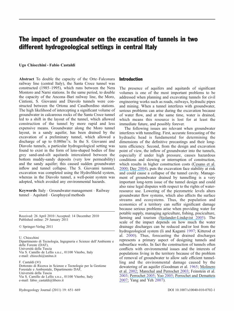
The specific cases where groundwater impacts tunnel-ling are the executive planning and excavation of fivetunnels created to double the capacity of the railways linesOrte-Falconara and Ancona-Bari in central Italy (Fig. 1).The former includes the Santa Croce tunnel between theNera Montoro and Narni (Umbria Region) stations, andthe latter includes the Moro, Cintioni, S. Giovanni andDiavolo tunnels between the Ortona and Casalbordino(Abruzzi Region) stations. The general contractor was theItalian Ferrovie dello Stato.
The geological and hydrogeological outline
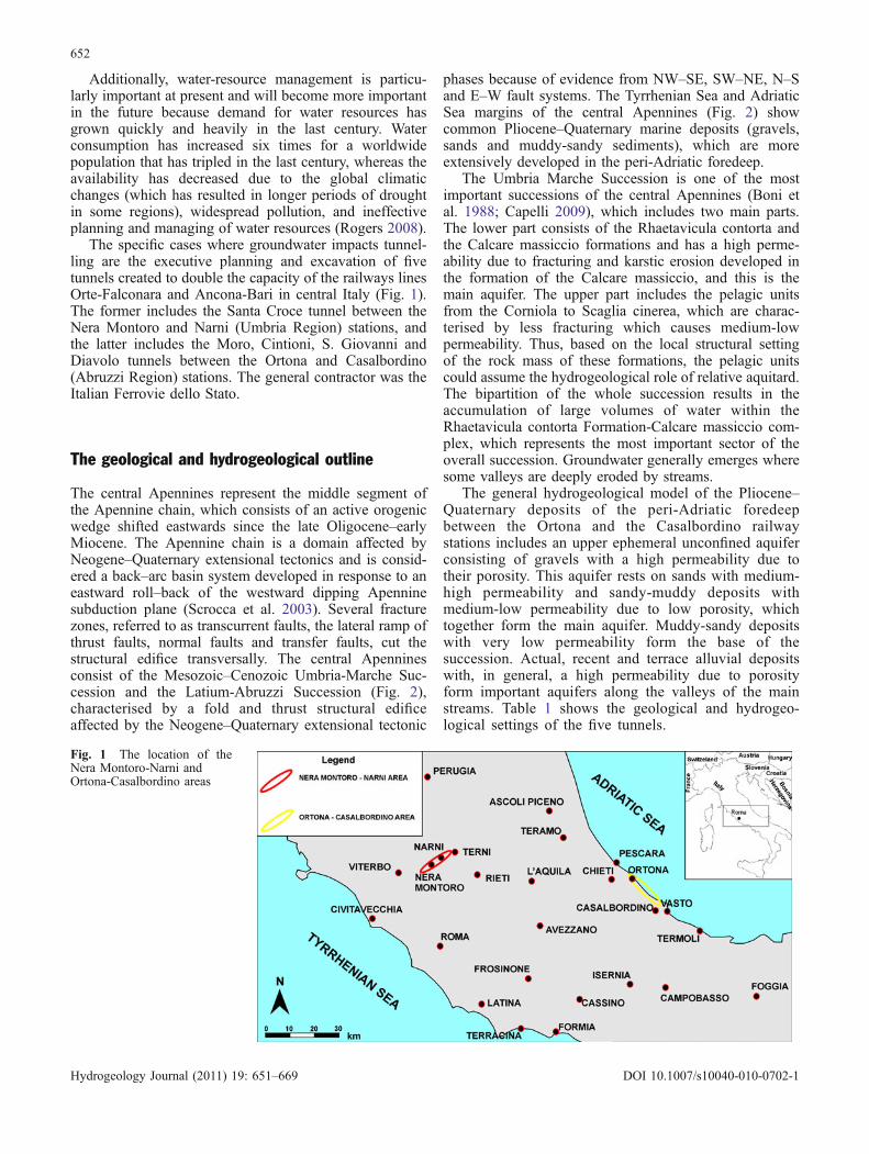
The central Apennines represent the middle segment ofthe Apennine chain, which consists of an active orogenicwedge shifted eastwards since the late Oligocene–earlyMiocene. The Apennine chain is a domain affected byNeogene–Quaternary extensional tectonics and is consid-ered a back–arc basin system developed in response to aneastward roll–back of the westward dipping Apenninesubduction plane (Scrocca et al. 2003). Several fracturezones, referred to as transcurrent faults, the lateral ramp ofthrust faults, normal faults and transfer faults, cut thestructural edifice transversally. The central Apenninesconsist of the Mesozoic–Cenozoic Umbria-Marche Suc-cession and the Latium-Abruzzi Succession (Fig. 2),characterised by a fold and thrust structural edificeaffected by the Neogene–Quaternary extensional tectonic
phases because of evidence from NW–SE, SW–NE, N–Sand E–W fault systems. The Tyrrhenian Sea and AdriaticSea margins of the central Apennines (Fig. 2) showcommon Pliocene–Quaternary marine deposits (gravels,sands and muddy-sandy sediments), which are moreextensively developed in the peri-Adriatic foredeep.
The Umbria Marche Succession is one of the mostimportant successions of the central Apennines (Boni etal. 1988; Capelli 2009), which includes two main parts.The lower part consists of the Rhaetavicula contorta andthe Calcare massiccio formations and has a high perme-ability due to fracturing and karstic erosion developed inthe formation of the Calcare massiccio, and this is themain aquifer. The upper part includes the pelagic unitsfrom the Corniola to Scaglia cinerea, which are charac-terised by less fracturing which causes medium-lowpermeability. Thus, based on the local structural settingof the rock mass of these formations, the pelagic unitscould assume the hydrogeological role of relative aquitard.The bipartition of the whole succession results in theaccumulation of large volumes of water within theRhaetavicula contorta Formation-Calcare massiccio com-plex, which represents the most important sector of theoverall succession. Groundwater generally emerges wheresome valleys are deeply eroded by streams.
The general hydrogeological model of the Pliocene–Quaternary deposits of the peri-Adriatic foredeepbetween the Ortona and the Casalbordino railwaystations includes an upper ephemeral unconfined aquiferconsisting of gravels with a high permeability due totheir porosity. This aquifer rests on sands with medium-high permeability and sandy-muddy deposits withmedium-low permeability due to low porosity, whichtogether form the main aquifer. Muddy-sandy depositswith very low permeability form the base of thesuccession. Actual, recent and terrace alluvial depositswith, in general, a high permeability due to porosityform important aquifers along the valleys of the mainstreams. Table 1 shows the geological and hydrogeo-logical settings of the five tunnels.
Fig. 1 The location of theNera Montoro-Narni andOrtona-Casalbordino areas
652
Hydrogeology Journal (2011) 19: 651–669 DOI 10.1007/s10040-010-0702-1
Methodology
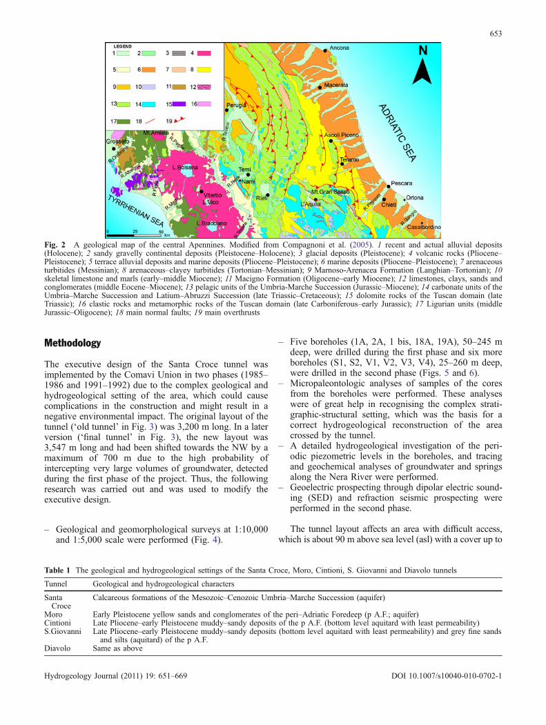
The executive design of the Santa Croce tunnel wasimplemented by the Comavi Union in two phases (1985–1986 and 1991–1992) due to the complex geological andhydrogeological setting of the area, which could causecomplications in the construction and might result in anegative environmental impact. The original layout of thetunnel (‘old tunnel’ in Fig. 3) was 3,200 m long. In a laterversion (‘final tunnel’ in Fig. 3), the new layout was3,547 m long and had been shifted towards the NW by amaximum of 700 m due to the high probability ofintercepting very large volumes of groundwater, detectedduring the first phase of the project. Thus, the followingresearch was carried out and was used to modify theexecutive design.
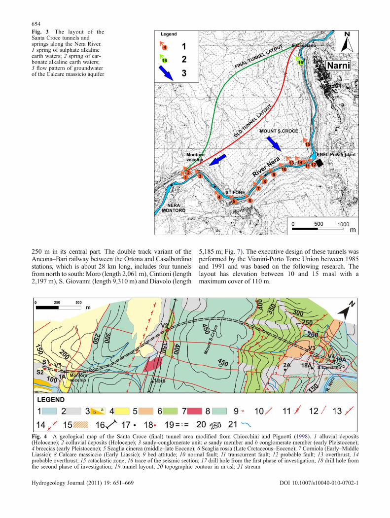
– Geological and geomorphological surveys at 1:10,000and 1:5,000 scale were performed (Fig. 4).
– Five boreholes (1A, 2A, 1 bis, 18A, 19A), 50–245 mdeep, were drilled during the first phase and six moreboreholes (S1, S2, V1, V2, V3, V4), 25–260 m deep,were drilled in the second phase (Figs. 5 and 6).
– Micropaleontologic analyses of samples of the coresfrom the boreholes were performed. These analyseswere of great help in recognising the complex strati-graphic-structural setting, which was the basis for acorrect hydrogeological reconstruction of the areacrossed by the tunnel.
– A detailed hydrogeological investigation of the peri-odic piezometric levels in the boreholes, and tracingand geochemical analyses of groundwater and springsalong the Nera River were performed.
– Geoelectric prospecting through dipolar electric sound-ing (SED) and refraction seismic prospecting wereperformed in the second phase.
The tunnel layout affects an area with difficult access,which is about 90 m above sea level (asl) with a cover up to
Fig. 2 A geological map of the central Apennines. Modified from Compagnoni et al. (2005). 1 recent and actual alluvial deposits(Holocene); 2 sandy gravelly continental deposits (Pleistocene–Holocene); 3 glacial deposits (Pleistocene); 4 volcanic rocks (Pliocene–Pleistocene); 5 terrace alluvial deposits and marine deposits (Pliocene–Pleistocene); 6 marine deposits (Pliocene–Pleistocene); 7 arenaceousturbitides (Messinian); 8 arenaceous–clayey turbitides (Tortonian–Messinian); 9 Marnoso-Arenacea Formation (Langhian–Tortonian); 10skeletal limestone and marls (early–middle Miocene); 11 Macigno Formation (Oligocene–early Miocene); 12 limestones, clays, sands andconglomerates (middle Eocene–Miocene); 13 pelagic units of the Umbria-Marche Succession (Jurassic–Miocene); 14 carbonate units of theUmbria–Marche Succession and Latium–Abruzzi Succession (late Triassic–Cretaceous); 15 dolomite rocks of the Tuscan domain (lateTriassic); 16 clastic rocks and metamorphic rocks of the Tuscan domain (late Carboniferous–early Jurassic); 17 Ligurian units (middleJurassic–Oligocene); 18 main normal faults; 19 main overthrusts
Table 1 The geological and hydrogeological settings of the Santa Croce, Moro, Cintioni, S. Giovanni and Diavolo tunnels
Tunnel Geological and hydrogeological characters
SantaCroce
Calcareous formations of the Mesozoic–Cenozoic Umbria–Marche Succession (aquifer)
Moro Early Pleistocene yellow sands and conglomerates of the peri–Adriatic Foredeep (p A.F.; aquifer)Cintioni Late Pliocene–early Pleistocene muddy–sandy deposits of the p A.F. (bottom level aquitard with least permeability)S.Giovanni Late Pliocene–early Pleistocene muddy–sandy deposits (bottom level aquitard with least permeability) and grey fine sands
and silts (aquitard) of the p A.F.Diavolo Same as above
653
Hydrogeology Journal (2011) 19: 651–669 DOI 10.1007/s10040-010-0702-1
250 m in its central part. The double track variant of theAncona–Bari railway between the Ortona and Casalbordinostations, which is about 28 km long, includes four tunnelsfrom north to south: Moro (length 2,061 m), Cintioni (length2,197 m), S. Giovanni (length 9,310 m) and Diavolo (length
5,185 m; Fig. 7). The executive design of these tunnels wasperformed by the Vianini-Porto Torre Union between 1985and 1991 and was based on the following research. Thelayout has elevation between 10 and 15 masl with amaximum cover of 110 m.
Fig. 3 The layout of theSanta Croce tunnels andsprings along the Nera River.1 spring of sulphate alkalineearth waters; 2 spring of car-bonate alkaline earth waters;3 flow pattern of groundwaterof the Calcare massicio aquifer
Fig. 4 A geological map of the Santa Croce (final) tunnel area modified from Chiocchini and Pignotti (1998). 1 alluvial deposits(Holocene); 2 colluvial deposits (Holocene); 3 sandy-conglomerate unit: a sandy member and b conglomerate member (early Pleistocene);4 breccias (early Pleistocene); 5 Scaglia cinerea (middle–late Eocene); 6 Scaglia rossa (Late Cretaceous–Eocene); 7 Corniola (Early–MiddleLiassic); 8 Calcare massiccio (Early Liassic); 9 bed attitude; 10 normal fault; 11 transcurrent fault; 12 probable fault; 13 overthrust; 14probable overthrust; 15 cataclastic zone; 16 trace of the seismic section; 17 drill hole from the first phase of investigation; 18 drill hole fromthe second phase of investigation; 19 tunnel layout; 20 topographic contour in m asl; 21 stream
654
Hydrogeology Journal (2011) 19: 651–669 DOI 10.1007/s10040-010-0702-1
– Geological and geomorphological surveys at scale1:5,000
– 140 boreholes– Mineralogic analyses of clay sampled during excava-
tion of the Cintioni and S. Giovanni tunnels– Texture analyses of the sands as well as fine sands and
silts sampled from the cores of boreholes– Laboratory geotechnic analyses on several undisturbed
samples of clays and standard penetration tests (SPT)in bore holes
– A detailed hydrogeological investigation of the peri-odic piezometric levels in wells and boreholes prior,during and after construction of the tunnels, and 200wells of small diameter and 20 piezometers, toconstruct a section of the Diavolo tunnel
The Santa Croce tunnel
Geological and geomorphological settingThe tunnel is located in the central part of the AmeliaMountains, between Narni (through the Mount Santa Croce,whose elevation is 400 masl) and the railway station of NeraMontoro, and is crossed by the Nera River which cuts thearea with a sigmoidal SW–NE trend, forming a deep gorge.The lithostratigraphic units pertain to the Umbria–Marche
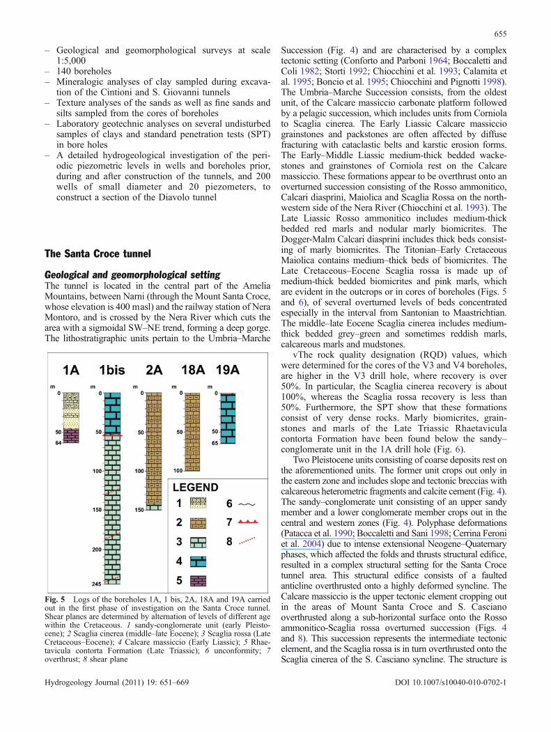
Succession (Fig. 4) and are characterised by a complextectonic setting (Conforto and Parboni 1964; Boccaletti andColi 1982; Storti 1992; Chiocchini et al. 1993; Calamita etal. 1995; Boncio et al. 1995; Chiocchini and Pignotti 1998).The Umbria–Marche Succession consists, from the oldestunit, of the Calcare massiccio carbonate platform followedby a pelagic succession, which includes units from Corniolato Scaglia cinerea. The Early Liassic Calcare massicciograinstones and packstones are often affected by diffusefracturing with cataclastic belts and karstic erosion forms.The Early–Middle Liassic medium-thick bedded wacke-stones and grainstones of Corniola rest on the Calcaremassiccio. These formations appear to be overthrust onto anoverturned succession consisting of the Rosso ammonitico,Calcari diasprini, Maiolica and Scaglia Rossa on the north-western side of the Nera River (Chiocchini et al. 1993). TheLate Liassic Rosso ammonitico includes medium-thickbedded red marls and nodular marly biomicrites. TheDogger-Malm Calcari diasprini includes thick beds consist-ing of marly biomicrites. The Titonian–Early CretaceousMaiolica contains medium–thick beds of biomicrites. TheLate Cretaceous–Eocene Scaglia rossa is made up ofmedium-thick bedded biomicrites and pink marls, whichare evident in the outcrops or in cores of boreholes (Figs. 5and 6), of several overturned levels of beds concentratedespecially in the interval from Santonian to Maastrichtian.The middle–late Eocene Scaglia cinerea includes medium-thick bedded grey–green and sometimes reddish marls,calcareous marls and mudstones.
vThe rock quality designation (RQD) values, whichwere determined for the cores of the V3 and V4 boreholes,are higher in the V3 drill hole, where recovery is over50%. In particular, the Scaglia cinerea recovery is about100%, whereas the Scaglia rossa recovery is less than50%. Furthermore, the SPT show that these formationsconsist of very dense rocks. Marly biomicrites, grain-stones and marls of the Late Triassic Rhaetaviculacontorta Formation have been found below the sandy–conglomerate unit in the 1A drill hole (Fig. 6).
Two Pleistocene units consisting of coarse deposits rest onthe aforementioned units. The former unit crops out only inthe eastern zone and includes slope and tectonic breccias withcalcareous heterometric fragments and calcite cement (Fig. 4).The sandy–conglomerate unit consisting of an upper sandymember and a lower conglomerate member crops out in thecentral and western zones (Fig. 4). Polyphase deformations(Patacca et al. 1990; Boccaletti and Sani 1998; Cerrina Feroniet al. 2004) due to intense extensional Neogene–Quaternaryphases, which affected the folds and thrusts structural edifice,resulted in a complex structural setting for the Santa Crocetunnel area. This structural edifice consists of a faultedanticline overthrusted onto a highly deformed syncline. TheCalcare massiccio is the upper tectonic element cropping outin the areas of Mount Santa Croce and S. Cascianooverthrusted along a sub-horizontal surface onto the Rossoammonitico-Scaglia rossa overturned succession (Figs. 4and 8). This succession represents the intermediate tectonicelement, and the Scaglia rossa is in turn overthrusted onto theScaglia cinerea of the S. Casciano syncline. The structure is
Fig. 5 Logs of the boreholes 1A, 1 bis, 2A, 18A and 19A carriedout in the first phase of investigation on the Santa Croce tunnel.Shear planes are determined by alternation of levels of different agewithin the Cretaceous. 1 sandy-conglomerate unit (early Pleisto-cene); 2 Scaglia cinerea (middle–late Eocene); 3 Scaglia rossa (LateCretaceous–Eocene); 4 Calcare massiccio (Early Liassic); 5 Rhae-tavicula contorta Formation (Late Triassic); 6 unconformity; 7overthrust; 8 shear plane
655
Hydrogeology Journal (2011) 19: 651–669 DOI 10.1007/s10040-010-0702-1
due to compressive bi-phase kinematics, specifically, an eventthat formed an anticline with the external overturned side, anda subsequent event, characterised by the breaking of theinternal part of the structure consisting of the Calcaremassiccio, which thrusts onto the front part of the structure.Due to this second event, the succession underlying the
Calcare massiccio has been deeply deformed and developedfolds and minor thrusts also documented by drill logs (Figs. 5and 6). The Calcare massiccio of the highly deformedsyncline is supposed to be capped through an overthrust bythe Rosso ammonitico-Scaglia rossa overturned succession,which resulted in the lowermost tectonic element. The S.Casciano fault has cut this structure and played the role of anout-of-sequence thrust (Morley 1988; Boyer 1992) or of anoverthrust reactivated as a low angle normal fault. Thesedeformations have been active since the Serravallian to lateMiocene (Chiocchini et al. 1993; Boncio et al. 1995;Calamita et al. 1995) and the deformation mechanism isreferred to as fault-propagation folding (Mitra 1990; Suppeand Medwedeff 1990). The subsequent multi-phase exten-sional Neogene–Quaternary tectonics is characterised bynormal faults trending NW–SE and dipping westwards,which indicates that the main part of the total extension isactive mainly with a left transcurrent component in a systemof rotation of blocks along transcurrent faults trendingE–W.
Geophysical prospectingA geoelectric survey using dipolar electric soundings (DES)allowed six classes of resistivity to be recognised (0–50; 51–100; 101–200; 201–500; 501–1,000; >1,000Ω/m). The class101–200 is poorly conductive and typical of permeablerocks. The other classes are very conductive (0–50) toconductive (51–100), both of which are related to rocks withlow permeability, and typically resistive (201–500) to veryresistive (>1,000), which characterise rocks with low to verylow permeability. The 0–50 class includes very conductive
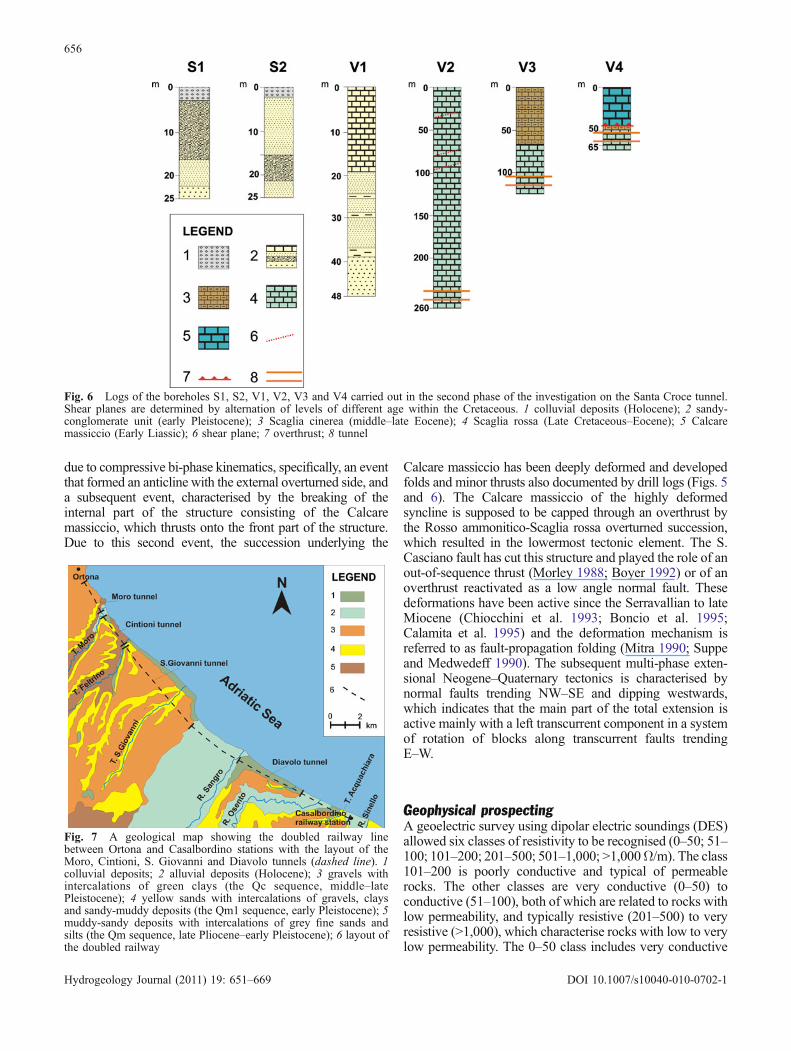
Fig. 6 Logs of the boreholes S1, S2, V1, V2, V3 and V4 carried out in the second phase of the investigation on the Santa Croce tunnel.Shear planes are determined by alternation of levels of different age within the Cretaceous. 1 colluvial deposits (Holocene); 2 sandy-conglomerate unit (early Pleistocene); 3 Scaglia cinerea (middle–late Eocene); 4 Scaglia rossa (Late Cretaceous–Eocene); 5 Calcaremassiccio (Early Liassic); 6 shear plane; 7 overthrust; 8 tunnel
Fig. 7 A geological map showing the doubled railway linebetween Ortona and Casalbordino stations with the layout of theMoro, Cintioni, S. Giovanni and Diavolo tunnels (dashed line). 1colluvial deposits; 2 alluvial deposits (Holocene); 3 gravels withintercalations of green clays (the Qc sequence, middle–latePleistocene); 4 yellow sands with intercalations of gravels, claysand sandy-muddy deposits (the Qm1 sequence, early Pleistocene); 5muddy-sandy deposits with intercalations of grey fine sands andsilts (the Qm sequence, late Pliocene–early Pleistocene); 6 layout ofthe doubled railway
656
Hydrogeology Journal (2011) 19: 651–669 DOI 10.1007/s10040-010-0702-1
formations like the Scaglia cinerea, which is characterised bylow permeability. The Scaglia rossa, Calcare massiccio andbreccias, which are affected by intense fracturing, are poorlyresistive and have medium to high permeability, are includedin the 101–200 class. The remaining classes (201–500; 501–1,000; >1,000) are referred to as the calcareous units anddisplay poor fracturing, are typically resistive to veryresistive, have low to very low permeability and a very lowwater content like some parts of the Rhaetavicula contortaFormation.
The electric pseudosections show that the south-westernbelt crossed by the old tunnel layout is characterised by highvolumes of the 101–200 resistivity class, which are referred
to as the Calcare massiccio-brecce complex. Consequently,the old layout is totally within this complex. Thus, this resultsuggested finding an alternative layout through further DES.The spontaneous potential distribution in the subsurfaceindicates that the area can be subdivided into two adjacentsectors separated by a NE–SW trending diagonal joining theNarni and Nera Montoro stations through Mount SantaCroce. The south-eastern sector is affected by groundwater,which is uniformly distributed and is included in the formerlayout. The north-western sector, on the other hand, showsonly some transversal directions of flow, of which the centraldirection is the most important. In fact, the new layoutcrosses this sector and appears to be more suitable than theoriginal layout. The geoelectric prospection confirms thegroundwater flow scheme (Fig. 3) of Chiocchini et al.(1987).
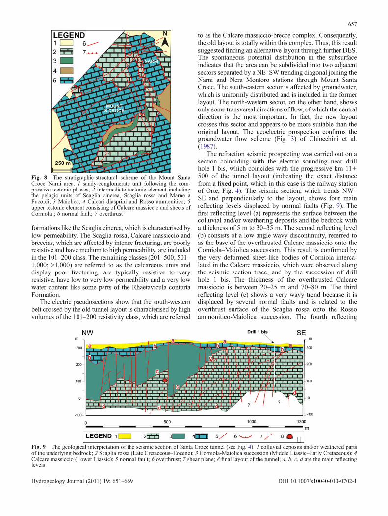
The refraction seismic prospecting was carried out on asection coinciding with the electric sounding near drillhole 1 bis, which coincides with the progressive km 11+500 of the tunnel layout (indicating the exact distancefrom a fixed point, which in this case is the railway stationof Orte; Fig. 4). The seismic section, which trends NW–SE and perpendicularly to the layout, shows four mainreflecting levels displaced by normal faults (Fig. 9). Thefirst reflecting level (a) represents the surface between thecolluvial and/or weathering deposits and the bedrock witha thickness of 5 m to 30–35 m. The second reflecting level(b) consists of a low angle wavy discontinuity, referred toas the base of the overthrusted Calcare massiccio onto theCorniola–Maiolica succession. This result is confirmed bythe very deformed sheet-like bodies of Corniola interca-lated in the Calcare massiccio, which were observed alongthe seismic section trace, and by the succession of drillhole 1 bis. The thickness of the overthrusted Calcaremassiccio is between 20–25 m and 70–80 m. The thirdreflecting level (c) shows a very wavy trend because it isdisplaced by several normal faults and is related to theoverthrust surface of the Scaglia rossa onto the Rossoammonitico-Maiolica succession. The fourth reflecting
Fig. 8 The stratigraphic-structural scheme of the Mount SantaCroce–Narni area. 1 sandy-conglomerate unit following the com-pressive tectonic phases; 2 intermediate tectonic element includingthe pelagic units of Scaglia cinerea, Scaglia rossa and Marne aFucoidi; 3 Maiolica; 4 Calcari diasprini and Rosso ammonitico; 5upper tectonic element consisting of Calcare massiccio and sheets ofCorniola ; 6 normal fault; 7 overthrust
Fig. 9 The geological interpretation of the seismic section of Santa Croce tunnel (see Fig. 4). 1 colluvial deposits and/or weathered partsof the underlying bedrock; 2 Scaglia rossa (Late Cretaceous–Eocene); 3 Corniola-Maiolica succession (Middle Liassic–Early Cretaceous); 4Calcare massiccio (Lower Liassic); 5 normal fault; 6 overthrust; 7 shear plane; 8 final layout of the tunnel; a, b, c, d are the main reflectinglevels
657
Hydrogeology Journal (2011) 19: 651–669 DOI 10.1007/s10040-010-0702-1
level (d) coincides with a deep discontinuity between theScaglia rossa and an undetermined bedrock in the south-eastern part of seismic section.
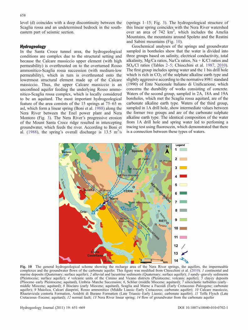
HydrogeologyIn the Santa Croce tunnel area, the hydrogeologicalconditions are complex due to the structural setting andbecause the Calcare massiccio upper element (with highpermeability) is overthrusted on to the overturned Rossoammonitico-Scaglia rossa succession (with medium-lowpermeability), which in turn is overthrusted onto thelowermost structural element made up of the Calcaremassiccio. Thus, the upper Calcare massiccio is anunconfined aquifer feeding the underlying Rosso ammo-nitico-Scaglia rossa complex, which is locally consideredto be an aquitard. The most important hydrogeologicalfeature of the area consists of the 15 springs at 75–65 masl, which form a linear spring (Boni et al. 1988) along theNera River between the Enel power plant and NeraMontoro (Fig. 3). The Nera River’s progressive erosionof the Mount Santa Croce ridge resulted in interceptinggroundwater, which feeds the river. According to Boni etal. (1988), the spring’s overall discharge is 13.5 m3/s
(springs 1–15; Fig. 3). The hydrogeological structure ofthis linear spring coincides with the Nera River watershedover an area of 742 km2, which includes the AmeliaMountains, the mountains around Spoleto and the Reatiniand Sabini mountains (Fig. 10).
Geochemical analyses of the springs and groundwatersampled in boreholes show that the water is divided intothree groups based on salinity, electrical conductivity, totalalkalinity, Mg/Ca ratios, Na/Ca ratios, Na + K/Cl ratios andSO4/Cl ratios (Tables 2–5; Chiocchini et al. 1987, 2010).The first group includes spring water and the 1 bis drill holewhich is rich in CO2 of the sulphate alkaline earth type andslightly aggressive according to the normative 8981 standard(1990) of Ente Nazionale Italiano di Unificazione, whichconcerns the durability of works consisting of concrete.Waters of the second group, sampled in 2A, 18A and 19Aboreholes, which met the Scaglia rossa aquitard, are of thecarbonate alkaline earth type. Waters of the third group,sampled in 1A drill hole, show intermediate values betweenthe former two groups and are of the carbonate sulphatealkaline earth type. The identical composition of the waterfrom 1A drill hole and spring water led to perfoming atracing test using fluorescein, which demonstrated that thereis a connection between these types of waters.
Fig. 10 The general hydrogeological scheme showing the recharge area of the Nera River springs, the aquifers, the impermeablecomplexes and the groundwater flows of the carbonate aquifer. This figure was modified from Chiocchini et al. (2010). 1 continental andmarine deposits (Quaternary; surface aquifer); 2 alluvial and lacustrine sediments (Quaternary; surface aquifer); 3 sandy–gravely sediments(Pleistocene; surface aquifer); 4 volcanic units of the Cimino and Vicano districts (Pleistocene; volcanic aquifer); 5 clayey deposits(Pliocene–early Pleistocene; aquitard), Umbria–Marche Succession; 6, Schlier (middle Miocene; aquitard); 7 siliciclastic turbidites (early–middle Miocene; aquitard); 8 Bisciaro (early Miocene; aquitard), Scaglia and Marne a Fucoidi (Early Cretaceous–Paleogene; carbonateaquifer); 9 Maiolica, Calcari diasprini, Rosso ammonitico (Middle Liassic–Early Cretaceous; carbonate aquifer); 10 Calcare massiccio,Rhaetavicula contorta Formation, Anidriti di Burano Formation (Late Triassic–Early Liassic; carbonate aquifer); 11 Tolfa Flysch (LateCretaceous–Eocene; aquitard); 12 normal fault; 13 Nera River linear spring; 14 flow of groundwater from the carbonate aquifer
658
Hydrogeology Journal (2011) 19: 651–669 DOI 10.1007/s10040-010-0702-1
The large volume of water from the linear springsuggests that the main aquifer consists of the lowermostCalcare massiccio underlying the Rosso ammonitico-Scaglia cinerea aquitard below the tunnel layout. Thestructural setting resulting from the fault-propagationfolding has probably allowed entrapment of water withhigh internal pressure in the Scaglia rossa aquitard restingon the Calcare massiccio. The piezometric level ofgroundwater, which was found in the 1 bis borehole at80 masl, rose to 114 masl through the normal faulttrending E–W close to borehole 1 bis (Fig. 4) due to theScaglia rossa aquitard’s internal pressure.
This hydrogeological investigation revealed that alongthe tunnel layout there are two types of groundwaterconnected to two different circuits feeding the sulphatealkaline earth water and the carbonate alkaline water(Tables 2 and 3). The former circuit flows towards the SWand NE (Chiocchini et al. 1987; Fig. 3). Thus, theunfavourable hydrogeological setting motivated the devel-opment of an alternative layout (Fig. 3) because of theprobability of running into the former circuit groundwater.
On the basis of the results from the geophysicalinvestigations, six boreholes have been drilled along thenew layout (Figs. 4 and 6); the discharge on thenorthwestern side of the Nera River of some springs hasbeen controlled and new geochemical analyses on thegroundwater and springs have been conducted. Theseanalyses confirm the sulphate alkaline earth compositionof springs and the carbonate alkaline earth composition ofgroundwater from the boreholes. The overall discharge ofsprings 1–4 and 15–17 (Fig. 3) on the northwestern side ofthe Nera River was about 0.923 m3/s. The piezometriclevel was at 125 masl in the V2 drill hole, at 192 masl inthe V3 drill hole and at 100 masl in the V4 drill hole.Because the tunnel layout is at 90 masl, it would haveprobably intercepted some perched water bodies of theScaglia rossa aquitard, the discharge of which has notbeen determined because pumping tests were impossible
to perform. Some permeability tests of the Lugeon typeyielded values of the hydraulic conductivity of Scagliarossa ranging between 4.3 – 4.8 × 10⁻⁶-10–4 m/s and1.67 – 5.6 × – 10–7-10–5 m/s.
Data of the tunnel excavationDuring excavation of the tunnel, the following data werecollected from the western portal (km 10+095) and theeastern portal (km 13+642): the lithostratigraphic units,the rock mass discontinuities and the water discharges(Fig. 11a). These data confirm the structural setting ofChiocchini et al. (1993) and Chiocchini and Pignotti(1998) and allowed for correlation of the geologicalsurvey (Fig. 4) with the subsurface data through a sectionalong the tunnel axis (Fig. 11b).
– Progressives km 10 + 095 to 10 + 300 have medium-fineyellow sands with intercalations of grey pelites and peatof the sandy-conglomerate unit.
– Progressives km 10 + 300 to 10 + 320: breccias withheterometric calcareous clasts.
– Progressives km 10 + 320 to 11 + 200: grainstones ofthe Calcare massiccio with intense fracturing betweenprogressives 10+500 and 11+000 and showing locallyextensive cataclastic belts close to a high angle faultsurface with strike N30°W and dip towards the W.
– Progressives km 11 + 200 to 11 + 325 have biomicritesshowing intense fracturing in a green clayey matrixreferred to as Corniola, and in contact with the Calcaremassiccio through a normal fault trending E–W.
– Progressives km 11 + 325 to 12 + 330 have a new sub-vertical normal fault trending E–W and dippingtowards the E, which marks the contact with medium-thin beds of pink marly biomicrites and red pelites, andwhich are sometimes lacking bedding due to intensecleavage, referred to as the Scaglia rossa. As far as km12 + 330, the Scaglia rossa is affected by a system of
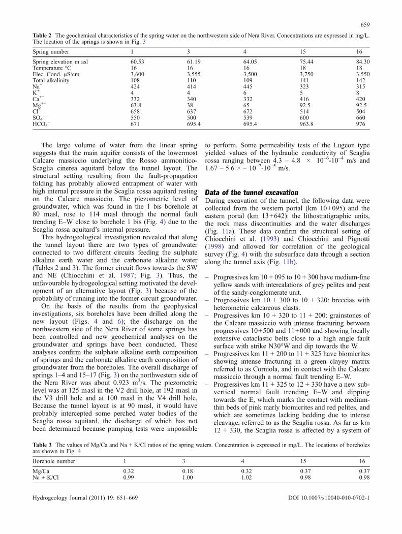
Table 2 The geochemical characteristics of the spring water on the northwestern side of Nera River. Concentrations are expressed in mg/L.The location of the springs is shown in Fig. 3
Spring number 1 3 4 15 16
Spring elevation m asl 60.53 61.19 64.05 75.44 84.30Temperature °C 16 16 16 18 18Elec. Cond. μS/cm 3,600 3,555 3,500 3,750 3,550Total alkalinity 108 110 109 141 142Na+ 424 414 445 323 315K+ 4 4 6 5 8Ca++ 332 340 332 416 420Mg++ 63.8 38 65 92.5 92.5Cl– 658 637 672 514 504SO4
–– 550 500 539 600 660HCO3
– 671 695.4 695.4 963.8 976
Table 3 The values of Mg/Ca and Na + K/Cl ratios of the spring waters. Concentration is expressed in mg/L. The locations of boreholesare shown in Fig. 4
Borehole number 1 3 4 15 16
Mg/Ca 0.32 0.18 0.32 0.37 0.37Na + K/Cl 0.99 1.00 1.02 0.98 0.98
659
Hydrogeology Journal (2011) 19: 651–669 DOI 10.1007/s10040-010-0702-1
pressure solution cleavage (tectonites of S-C type;Lister and Snoke 1984) and shows some reverse shearplanes showing strike with E–W and N25°W trend anddip towards the W.
– Progressives km 12 + 330 to 12 + 840 have sub-horizontal and slightly fractured medium-thick beds ofbiomicrites of Corniola. The contact with the Scagliarossa is marked by a zone of intense deformationshowing several shear planes trending between N18°and N27°W and dipping towards the W inside 60–70 mof the breccias fault. The surface of a low angle reversefault trending N20°W lies 60 m beyond the tectoniccontact with a limited cataclastic belt. Futher on, as faras the next tectonic contact, the Corniola shows non-deformed beds dipping 16° towards the E.
– Progressives km 12 + 840 to 13 + 365 are part of theScaglia rossa affected by intense fracturing and show-ing cataclastic belts (tectonites of S-C type). Betweenprogressives 12 + 950 and 13 + 000 the Scaglia rossa isoverthrusted onto calcareous marls and grey-greenpelites of the Scaglia cinerea in a zone of the brecciafault. A few metres beyond this contact a sub-verticalnormal fault trending N10°W again marks the contactwith the fractured Scaglia rossa.
– Progressives km 13 + 365 to 13 + 490 contain marls,calcareous marls and grey-green and reddish peliteswith cleavage of the Scaglia cinerea in tectonic contactwith the precedent unit through sub-vertical surfaces ofnormal faults trending between N15° and N22°W.
– Progressives km 13 + 490 to 13 + 590 are part of theScaglia rossa in stratigraphic contact with the precedentunits.
– Progressives km 13 + 590 to 13 + 642 are part of theCalcare massiccio overthrusted on to the Scagliacinerea and Scaglia rossa.
The contact between Scaglia rossa and Corniolasurveyed in the tunnel between km 12 and km 13
(Fig. 11) corresponds to the surface overthrust front ofScaglia rossa onto the Scaglia cinerea of the S. Cascianosyncline. The tectonic overlapping of younger formationson to older formations has been recognised in severalareas of the Umbria-Marche Succession (Cipollari andCosentino 1995). Groundwater has been detected in 12tunnel sections between km 11+280 and km 13+164 withan overall discharge of 0.017 m3/s, which suggests that theScaglia rossa aquitard hosts separated perched waterbodies due to an anisotropic distribution of fracturingand cleavage within the rock mass.
The Moro, Cintioni, S. Giovanni and Diavolotunnels
Geological and geomorphological settingThe hill belt between Ortona and the Casalbordino railwaystation are included in the peri-Adriatic foredeep, which islocated between the central Apennine chain and thecentral Adriatic Sea foreland (Crescenti 1971; Crescentiet al. 1980; Casnedi et al. 1981; Cantalamessa et al. 1986;Vezzani and Ghisetti 1988; Centamore and Micarelli1991; Ori et al. 1991; Ghisetti et al. 1994; Bigi et al.1995). Six depositional sequences have been recognised inthe Pliocene–Pleistocene sediments of this area: P1b of theearly Pliocene, P2 of the late Pliocene, Qm of the latePliocene pro parte–early Pleistocene, Q1 of the earlyPleistocene, Qc1 and Qc2 of the middle–late Pleistocene(Cantalamessa et al. 1986).
The hills are characterised by large flat-top areas withelevations between 125 m and 25 masl, separated byvalleys and streams with a prevailing WSW–ENE trend.The main streams are, from N to S, the Moro Torrent, theCintioni Torrent, the Feltrino Torrent, the S. GiovanniTorrent, the Sangro River, the Diavolo Torrent, the OsentoRiver and the Acquachiara Torrent. The geological survey,the logs of 140 boreholes and the excavation of tunnels
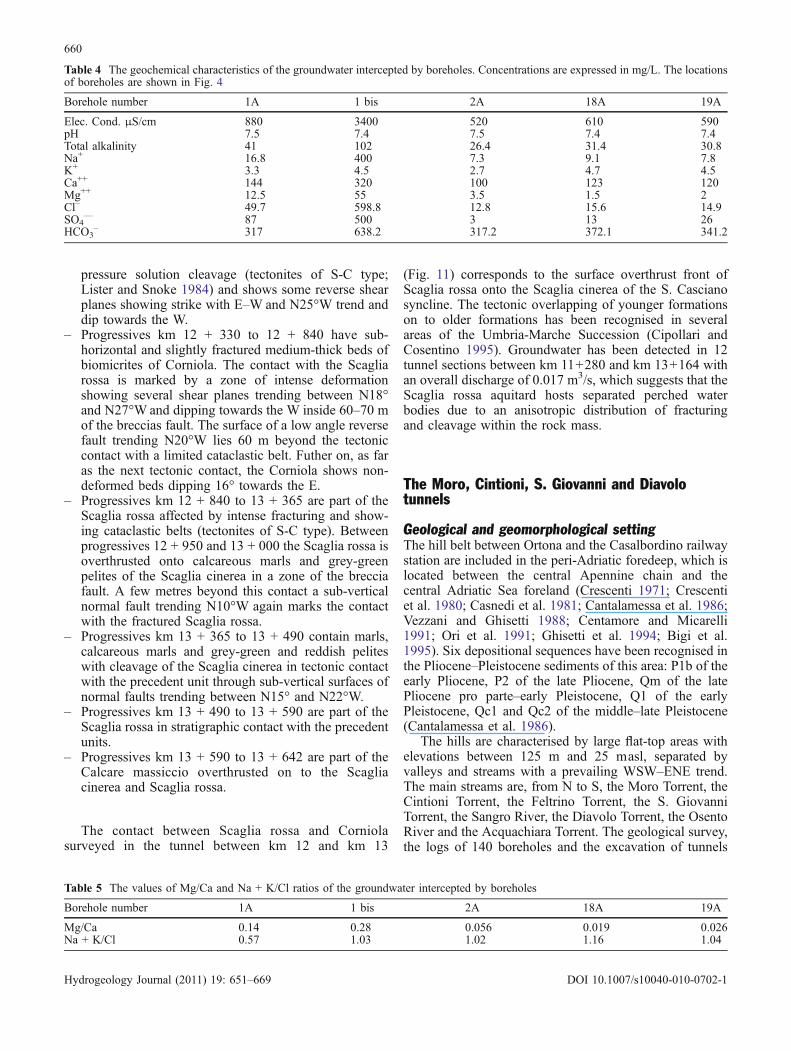
Table 4 The geochemical characteristics of the groundwater intercepted by boreholes. Concentrations are expressed in mg/L. The locationsof boreholes are shown in Fig. 4
Borehole number 1A 1 bis 2A 18A 19A
Elec. Cond. μS/cm 880 3400 520 610 590pH 7.5 7.4 7.5 7.4 7.4Total alkalinity 41 102 26.4 31.4 30.8Na+ 16.8 400 7.3 9.1 7.8K+ 3.3 4.5 2.7 4.7 4.5Ca++ 144 320 100 123 120Mg++ 12.5 55 3.5 1.5 2Cl– 49.7 598.8 12.8 15.6 14.9SO4
–– 87 500 3 13 26HCO3
– 317 638.2 317.2 372.1 341.2
Table 5 The values of Mg/Ca and Na + K/Cl ratios of the groundwater intercepted by boreholes
Borehole number 1A 1 bis 2A 18A 19A
Mg/Ca 0.14 0.28 0.056 0.019 0.026Na + K/Cl 0.57 1.03 1.02 1.16 1.04
660
Hydrogeology Journal (2011) 19: 651–669 DOI 10.1007/s10040-010-0702-1
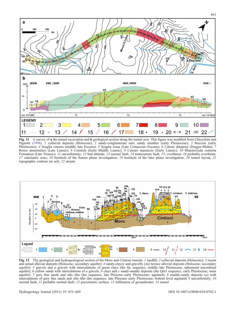
Fig. 11 A survey of a the tunnel excavation and b geological section along the tunnel axis. This figure was modified from Chiocchini andPignotti (1998). 1 colluvial deposits (Holocene); 2 sandy-conglomerate unit: sandy member (early Pleistocene); 3 breccias (earlyPleistocene); 4 Scaglia cinerea (middle–late Eocene); 5 Scaglia rossa (Late Cretaceous–Eocene); 6 Calcari diasprini (Dogger-Malm); 7Rosso ammonitico (Late Liassic); 8 Corniola (Early–Middle Liassic); 9 Calcare massiccio (Early Liassic); 10 Rhaetavicula contortaFormation (Late Triassic); 11 unconformity; 12 bed attitude; 13 normal fault; 14 transcurrent fault; 15, overthrust; 16 probable overthrust;17 cataclastic zone; 18 borehole of the former phase investigation; 19 borehole of the later phase investigation; 20 tunnel layout; 21topographic contour (m asl); 22 stream
Fig. 12 The geological and hydrogeological section of the Moro and Cintioni tunnels. 1 landfill; 2 colluvial deposits (Holocene); 3 recentand actual alluvial deposits (Holocene; secondary aquifer); 4 sandy-clayey and gravelly (4a) terrace alluvial deposits (Holocene; secondaryaquifer); 5 gravels and a gravels with intercalations of green clays (the Qc sequence, middle–late Pleistocene; ephemeral unconfinedaquifer); 6 yellow sands with intercalations of a gravels, b clays and c sandy-muddy deposits (the Qm1 sequence, early Pleistocene; mainaquifer); 7 grey fine sands and silts (the Qm sequence, late Pliocene–early Pleistocene; aquitard); 8 muddy-sandy deposits (a) withintercalations of grey fine sands and silts (the Qm sequence, late Pliocene–early Pleistocene; bottom level aquitard) 9 unconformity; 10normal fault; 11 probable normal fault; 12 piezometric surface; 13 infiltration of groundwater; 14 tunnel
661
Hydrogeology Journal (2011) 19: 651–669 DOI 10.1007/s10040-010-0702-1
allowed for recognition of a succession consisting of thesequences Qm, Qm1 and Qc (Figs. 7, 12, 13 and 14).
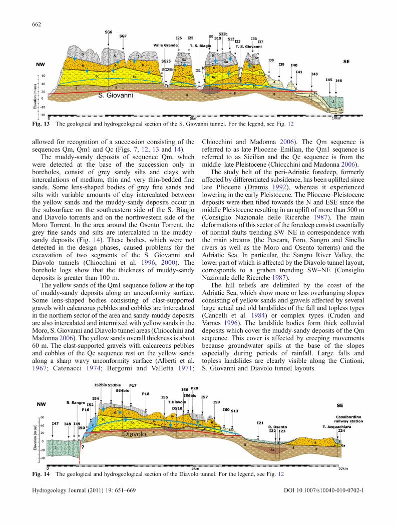
The muddy-sandy deposits of sequence Qm, whichwere detected at the base of the succession only inboreholes, consist of grey sandy silts and clays withintercalations of medium, thin and very thin-bedded finesands. Some lens-shaped bodies of grey fine sands andsilts with variable amounts of clay intercalated betweenthe yellow sands and the muddy-sandy deposits occur inthe subsurface on the southeastern side of the S. Biagioand Diavolo torrents and on the northwestern side of theMoro Torrent. In the area around the Osento Torrent, thegrey fine sands and silts are intercalated in the muddy-sandy deposits (Fig. 14). These bodies, which were notdetected in the design phases, caused problems for theexcavation of two segments of the S. Giovanni andDiavolo tunnels (Chiocchini et al. 1996, 2000). Theborehole logs show that the thickness of muddy-sandydeposits is greater than 100 m.
The yellow sands of the Qm1 sequence follow at the topof muddy-sandy deposits along an unconformity surface.Some lens-shaped bodies consisting of clast-supportedgravels with calcareous pebbles and cobbles are intercalatedin the northern sector of the area and sandy-muddy depositsare also intercalated and intermixed with yellow sands in theMoro, S. Giovanni and Diavolo tunnel areas (Chiocchini andMadonna 2006). The yellow sands overall thickness is about60 m. The clast-supported gravels with calcareous pebblesand cobbles of the Qc sequence rest on the yellow sandsalong a sharp wavy unconformity surface (Alberti et al.1967; Catenacci 1974; Bergomi and Valletta 1971;
Chiocchini and Madonna 2006). The Qm sequence isreferred to as late Pliocene–Emilian, the Qm1 sequence isreferred to as Sicilian and the Qc sequence is from themiddle–late Pleistocene (Chiocchini and Madonna 2006).
The study belt of the peri-Adriatic foredeep, formerlyaffected by differentiated subsidence, has been uplifted sincelate Pliocene (Dramis 1992), whereas it experiencedlowering in the early Pleistocene. The Pliocene–Pleistocenedeposits were then tilted towards the N and ESE since themiddle Pleistocene resulting in an uplift of more than 500 m(Consiglio Nazionale delle Ricerche 1987). The maindeformations of this sector of the foredeep consist essentiallyof normal faults trending SW–NE in correspondence withthe main streams (the Pescara, Foro, Sangro and Sinellorivers as well as the Moro and Osento torrents) and theAdriatic Sea. In particular, the Sangro River Valley, thelower part of which is affected by the Diavolo tunnel layout,corresponds to a graben trending SW–NE (ConsiglioNazionale delle Ricerche 1987).
The hill reliefs are delimited by the coast of theAdriatic Sea, which show more or less overhanging slopesconsisting of yellow sands and gravels affected by severallarge actual and old landslides of the fall and topless types(Cancelli et al. 1984) or complex types (Cruden andVarnes 1996). The landslide bodies form thick colluvialdeposits which cover the muddy-sandy deposits of the Qmsequence. This cover is affected by creeping movementsbecause groundwater spills at the base of the slopesespecially during periods of rainfall. Large falls andtopless landslides are clearly visible along the Cintioni,S. Giovanni and Diavolo tunnel layouts.
Fig. 13 The geological and hydrogeological section of the S. Giovanni tunnel. For the legend, see Fig. 12
Fig. 14 The geological and hydrogeological section of the Diavolo tunnel. For the legend, see Fig. 12
662
Hydrogeology Journal (2011) 19: 651–669 DOI 10.1007/s10040-010-0702-1
HydrogeologyThe study area is characterised by a hydrogeological modelwith five complexes (Figs. 12–14). The upper ephemeralunconfined aquifer consists of the gravel of the Qc sequenceand has high permeability due to the porosity. This aquiferrests on the yellow sands of the Qm1 sequence withmedium-high permeability (10–7–10–3 m/s) and the sandy-muddy deposits with medium-low permeability due to lowporosity, which together form the main aquifer. This aquiferrests on the muddy-sandy deposits of the Qm sequence withvery low permeability (10–9 m/s), which represent thebottom level aquitard. The fourth complex is made up ofthe lens-shaped bodies of grey fine sands and silts withmedium-low permeability due to low porosity (locallyreferred to as aquitards) intercalated between the muddy-sandy deposits and the yellow sand aquifer. The fifthcomplex includes the aquifer consisting of actual, recentand terrace alluvial deposits with, in general, a highpermeability due to high porosity. Because the tunnel’slayout is affected marginally by this complex, it isconsidered a secondary aquifer.
The hydrogeological sections (Figs. 12–14) showthat the main aquifer, with a maximum thickness ofabout 60 m, contains groundwater fed by infiltrationfrom the gravel ephemeral aquifer. The horizontal hydraulicgradient is 0.01–0.02, and the vertical hydraulic head is 0.4–0.6. The groundwater flow is probably conditioned by theheterogeneity of the aquifer which is characterised by anotable hydraulic anisotropy. Thus, the piezometricsurface shows a concave shape due to several valleyincisions, which cut the Moro, Cintioni and S. Giovannitunnels and drain the groundwater. This drainage isactive and spills into the colluvial deposits which rest atthe base of slopes.
Solutions adopted to overcome the interferenceof the tunnel’s layout with groundwaterDuring the design phase, the hydrogeological setting ofthe S. Giovanni and Diavolo tunnels was not correctlyreconstructed because the real lithostratigraphic setting ofthe succession was oversimplified and misinterpreted.This misinterpretation resulted in serious problems duringthe excavation works. Conversely, a more careful execu-tive design of the Moro tunnel allowed a suitable andreliable interpretation of the lithostratigraphic and hydro-geological setting. About 100 texture analyses on sandyand muddy samples from cores were carried out to betterunderstand the hydraulic conductivity values of the yellowsand aquifer, the grey fine sand-and-silts aquitard and themuddy-sandy deposits.
Moro tunnelThe hydrogeological section shows that the Moro tunnellayout (Fig. 12) was totally submerged (Chiocchini et al.1994). Thus, a preliminary draining tunnel was plannedand excavated by a LOVAT model m-157 series 6500Tunnel Boring Machine (TBM), which consisted of three
parts: a cutting head, a central machine body and aterminal body with an expansion ring of the pre-casting.The discharge of the groundwater near the southern portal(around km 2+357) was about 0.003 m3/s. This volumehas grown to 0.013 m3/s between km 2+540 and km 2+830, to 0.075 m3/s between km 3+380 and km 3+510,and to 0.080 m3/s further on (Fig. 15). A body of grey finesands and silts with high internal pressure was hit atprogressive km 4+010, which resulted in an abundantinflow of water and mud inside the pre-casted tunnel. Thetunnel excavation was completed in 134 days and, for thedefinitive tunnel, it was realised that the preliminarydraining tunnel section needed to be utilized.
S. Giovanni tunnelDifficulties arose during excavation of this tunnel betweenthe S. Biagio and S. Giovanni torrents because sandy-muddy materials not recognised during the design phaseswere encountered at the km 12+878 progressive (Fig. 16;Chiocchini and Giorelli 1994); thus, 15 boreholes weredrilled between km 12 + 855 and km 14+310. The logsenabled recognition of a lens-shaped body of grey finesands and silts 622 m long and with a maximum thicknessof 26 m between km 12+878 and km 13+600 and asecond similar body 330 m long with a maximumthickness of 12 m between km 14 + 600 and km 13+300. The hydraulic conductivity shows values on the orderof 10–5 m/s for the yellow sand aquifer, 10–7–10–6 m/s forthe grey fine sand-and-silt aquitard and 10–9-10–8 m/s forthe muddy-sandy deposits . Under undisturbed conditions,the grey fine sand-and-silt aquitard did not show asignificant transfer of water to the muddy-sandy deposits.To bypass the complex hydrogeological setting, theHydroShield system was utilised. This type of approachwas carried out by the Ferrofir Union for the excavation oftwo railway tunnels in fine sandy formations in Rome(Pandolfo 1986). The excavation of the face is made by asix-arm rotating disk and the stability of the tunnel sectionis ensured by mud pressure regulation, which is separatedin the remaining part of the excavator by a metallicdiaphragm. This pressure is controlled by a “cushion ofair” that is a chamber filled by a compressor station, whichacts to regulate the mud pressure on the face. Excavationof the remaining 952 m of the tunnel lasted 123 days.
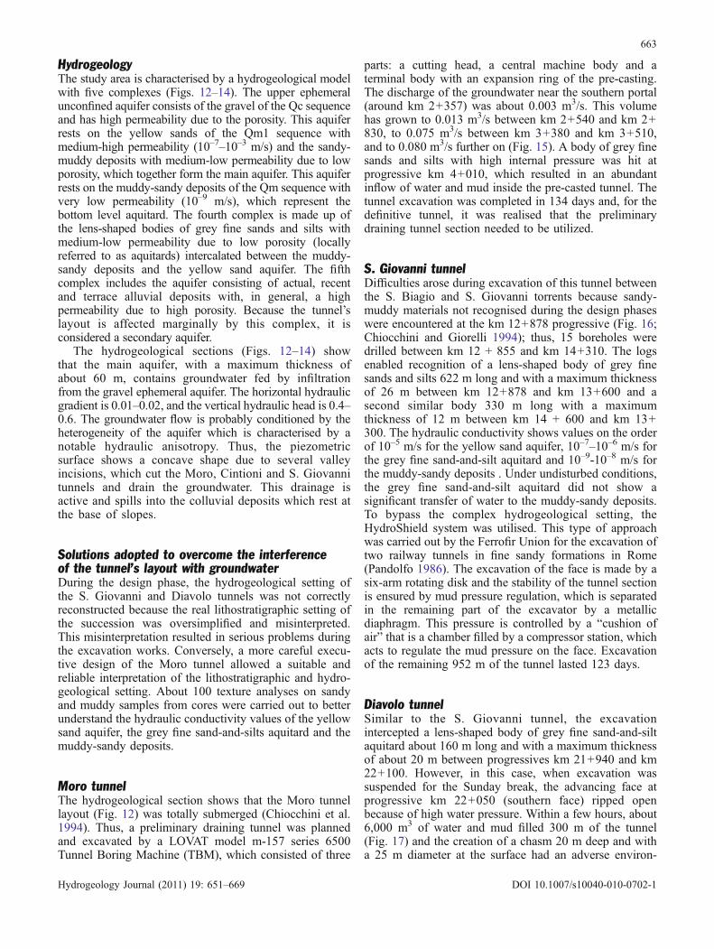
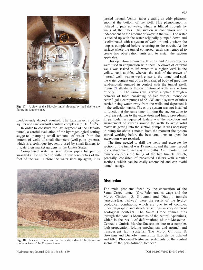
Diavolo tunnelSimilar to the S. Giovanni tunnel, the excavationintercepted a lens-shaped body of grey fine sand-and-siltaquitard about 160 m long and with a maximum thicknessof about 20 m between progressives km 21+940 and km22+100. However, in this case, when excavation wassuspended for the Sunday break, the advancing face atprogressive km 22+050 (southern face) ripped openbecause of high water pressure. Within a few hours, about6,000 m3 of water and mud filled 300 m of the tunnel(Fig. 17) and the creation of a chasm 20 m deep and witha 25 m diameter at the surface had an adverse environ-
663
Hydrogeology Journal (2011) 19: 651–669 DOI 10.1007/s10040-010-0702-1

mental effect (Fig. 18); however, neither flora nor faunawere affected by the loss of water. One day later duringexcavation at the km 21+950 progressive (northern face)effluent water was observed from yellow sands and 24 hlater a 10 m section of an unlined arch collapsed. Anintervention carried out in two phases consisted of (1)injection of cement mixtures into the tunnel to block thegravitational phenomena and (2) improving the groundstability, which was prone to failure, by a compactiongrouting operation and a claquage treatment with a mix ofwater, cement and bentonite. These unexpected and abruptfailures, after evacuation of flowed material from thetunnel section, led to a very careful investigation of thehydrogeological conditions of this section of the tunnel tofind out the best solution for completing the tunnel
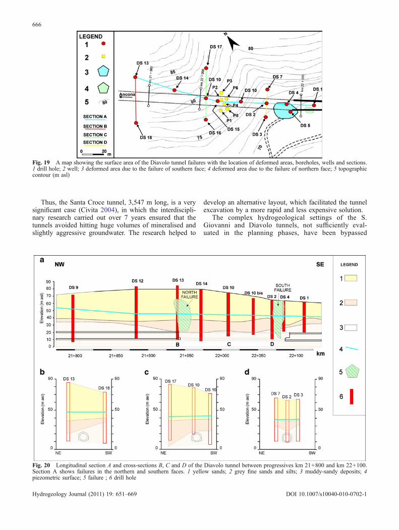
excavation (Chiocchini et al. 2000). Consequently, 14boreholes were drilled, the logs (Fig. 19) of which showthat the grey fine sand-and-silt aquitard is intercalatedbetween the yellow sand aquifer and the muddy-sandyaquitard bottom level of much lower permeability(Fig. 20). Also, in this case, a significant transfer of waterfrom the sand-and-silt aquitard to the muddy-sandyaquitard bottom level has not been noted.
To study the hydraulic setting of this sector of tunnel, fourpiezometers were installed in boreholes and six wells (P1,P2, P3, P4, P5, P6; Fig. 19) were drilled. The Lefrancpermeability tests under variable head conditions show thatthe hydraulic conductivity values are 3.9 – 10.5×10⁻⁵ m/sfor the yellow sands aquifer, 8.6×10⁻⁷– 4.6×10⁻⁶ m/s forthe grey fine sand-and-silt aquitard, and 2.7×10⁻⁸ m/s for the
Fig. 15 The trend of groundwater discharge during the excavation of the Moro tunnel. The maximum discharge of 0.080 m3/s wasregistered about 1,000 m away from the northern portal. This figure was modified from Chiocchini et al. (1994)
Fig. 16 A lithostratigraphic and hydrogeological section between progressives km 12+855 and km 14+310 of the S. Giovanni tunnel.This figure was modified from Chiocchini et al. (2000). 1 soil (Holocene); 2 colluvial deposits (Holocene); 3 gravels with green claysintercalations (the Qc sequence, middle–late Pleistocene); 4 yellow sands (a) with a intercalations of sandy-muddy deposits (the Qm1sequence, early Pleistocene); 5 grey fine sands and silts (the Qm sequence, late Pliocene–early Pleistocene); 6 muddy-sandy deposits (theQm sequence, late Pliocene–early Pleistocene); 7 piezometric surface; 8 tunnel; 9 borehole
664
Hydrogeology Journal (2011) 19: 651–669 DOI 10.1007/s10040-010-0702-1
muddy-sandy deposit aquitard. The transmissivity of theaquifer and sand-and-silt aquitard complex is 2×10⁻⁴ m2/s.
In order to construct the last segment of the Daivolotunnel, a careful evaluation of the hydrogeological settingsuggested pumping small amounts of water from thebottom of wells of small diameters (well-point system),which is a technique frequently used by small farmers toirrigate their market gardens in the Unites States.
Compressed water is sent down pipes by pumpsarranged at the surface to within a few centimetres of thefoot of the well. Before the water rises up again, it is
passed through Venturi tubes creating an eddy phenom-enon at the bottom of the well. This phenomenon isutilised to pick up water, which is filtered through thewalls of the tubes. The suction is continuous and isindependent of the amount of water in the well. The wateris sucked up with the water originally pumped down andis eliminated with a system of weirs in tanks, where theloop is completed before returning to the circuit. At thesurface where the tunnel collapsed, earth was removed tocreate two observation units and to install the suctionapparatus.
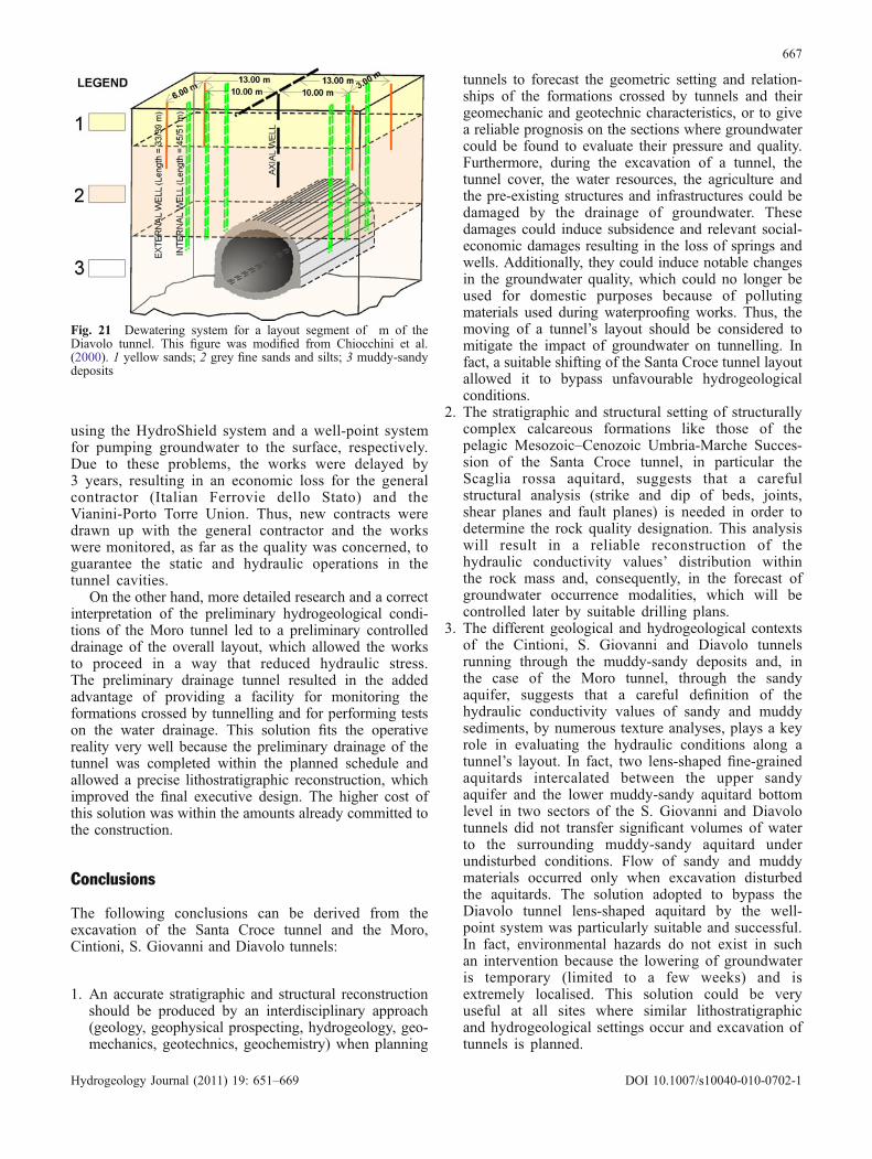
This operation required 200 wells, and 20 piezometerswere used in conjunction with them. A crown of externalwells was tasked to lift water to a higher level in theyellow sand aquifer, whereas the task of the crown ofinternal wells was to work closer to the tunnel and suckthe water content out of the lens-shaped body of grey finesand-and-silt aquitard in contact with the tunnel itself.Figure 21 illustrates the distribution of wells in a sectionof only 6 m. The various wells were supplied through anetwork of tubes consisting of five vertical monobloccentrifugal electropumps of 55 kW, and a system of tubescarried rising water away from the wells and deposited itin the collection tanks. The entire system was not installedto function at the same time, limiting the suction zone tothe areas relating to the excavation and lining procedures.In particular, a requested feature was the selection andarrangement of screens around the wells to avoid solidmaterials getting into the suction pumps. It was necessaryto pump for about a month from the moment the systemstarted working before the best conditions to open theexcavation were reached.
The time needed to drill the wells and excavate thesection of the tunnel was 17 months, and the time neededto construct the tunnel was 11 months. An important finalremark concerns the lining of the five tunnels, which,generally, consisted of pre-casted ashlars with circularsections, which can be easily assembled and can avoidtunnel leakage.
Discussion
The main problems faced by the excavation of theSanta Croce tunnel (Orte-Falconara railway) and theMoro, Cintioni, S. Giovanni and Diavolo tunnels(Ancona-Bari railway) were the result of the hydro-geological conditions, which are due to of complexlithostratigraphic and structural settings in very differentgeological contexts. The Santa Croce tunnel runsthrough the Amelia Mountains of the central Apennines,which is the result of deformations of the Mesozoic–Cenozoic Umbria-Marche Succession due to a complexfault-propagation folding mechanism and normal andtranscurrent fault systems. The Moro, Cintioni, S.Giovanni and Diavolo tunnels run through the upliftedand tilted Pliocene–Pleistocene sediments of the centralsector of the peri-Adriatic foredeep.
Fig. 17 A view of the Diavolo tunnel flooded by mud due to thefailure in southern face
Fig. 18 A view of the chasm at the surface due to the failure insouthern face of the Diavolo tunnel
665
Hydrogeology Journal (2011) 19: 651–669 DOI 10.1007/s10040-010-0702-1
Thus, the Santa Croce tunnel, 3,547 m long, is a verysignificant case (Civita 2004), in which the interdiscipli-nary research carried out over 7 years ensured that thetunnels avoided hitting huge volumes of mineralised andslightly aggressive groundwater. The research helped to
develop an alternative layout, which facilitated the tunnelexcavation by a more rapid and less expensive solution.
The complex hydrogeological settings of the S.Giovanni and Diavolo tunnels, not sufficiently eval-uated in the planning phases, have been bypassed
Fig. 19 A map showing the surface area of the Diavolo tunnel failures with the location of deformed areas, boreholes, wells and sections.1 drill hole; 2 well; 3 deformed area due to the failure of southern face; 4 deformed area due to the failure of northern face; 5 topographiccontour (m asl)
Fig. 20 Longitudinal section A and cross-sections B, C and D of the Diavolo tunnel between progressives km 21+800 and km 22+100.Section A shows failures in the northern and southern faces. 1 yellow sands; 2 grey fine sands and silts; 3 muddy-sandy deposits; 4piezometric surface; 5 failure ; 6 drill hole
666
Hydrogeology Journal (2011) 19: 651–669 DOI 10.1007/s10040-010-0702-1
using the HydroShield system and a well-point systemfor pumping groundwater to the surface, respectively.Due to these problems, the works were delayed by3 years, resulting in an economic loss for the generalcontractor (Italian Ferrovie dello Stato) and theVianini-Porto Torre Union. Thus, new contracts weredrawn up with the general contractor and the workswere monitored, as far as the quality was concerned, toguarantee the static and hydraulic operations in thetunnel cavities.
On the other hand, more detailed research and a correctinterpretation of the preliminary hydrogeological condi-tions of the Moro tunnel led to a preliminary controlleddrainage of the overall layout, which allowed the worksto proceed in a way that reduced hydraulic stress.The preliminary drainage tunnel resulted in the addedadvantage of providing a facility for monitoring theformations crossed by tunnelling and for performing testson the water drainage. This solution fits the operativereality very well because the preliminary drainage of thetunnel was completed within the planned schedule andallowed a precise lithostratigraphic reconstruction, whichimproved the final executive design. The higher cost ofthis solution was within the amounts already committed tothe construction.
Conclusions
The following conclusions can be derived from theexcavation of the Santa Croce tunnel and the Moro,Cintioni, S. Giovanni and Diavolo tunnels:
1. An accurate stratigraphic and structural reconstructionshould be produced by an interdisciplinary approach(geology, geophysical prospecting, hydrogeology, geo-mechanics, geotechnics, geochemistry) when planning
tunnels to forecast the geometric setting and relation-ships of the formations crossed by tunnels and theirgeomechanic and geotechnic characteristics, or to givea reliable prognosis on the sections where groundwatercould be found to evaluate their pressure and quality.Furthermore, during the excavation of a tunnel, thetunnel cover, the water resources, the agriculture andthe pre-existing structures and infrastructures could bedamaged by the drainage of groundwater. Thesedamages could induce subsidence and relevant social-economic damages resulting in the loss of springs andwells. Additionally, they could induce notable changesin the groundwater quality, which could no longer beused for domestic purposes because of pollutingmaterials used during waterproofing works. Thus, themoving of a tunnel’s layout should be considered tomitigate the impact of groundwater on tunnelling. Infact, a suitable shifting of the Santa Croce tunnel layoutallowed it to bypass unfavourable hydrogeologicalconditions.
2. The stratigraphic and structural setting of structurallycomplex calcareous formations like those of thepelagic Mesozoic–Cenozoic Umbria-Marche Succes-sion of the Santa Croce tunnel, in particular theScaglia rossa aquitard, suggests that a carefulstructural analysis (strike and dip of beds, joints,shear planes and fault planes) is needed in order todetermine the rock quality designation. This analysiswill result in a reliable reconstruction of thehydraulic conductivity values’ distribution withinthe rock mass and, consequently, in the forecast ofgroundwater occurrence modalities, which will becontrolled later by suitable drilling plans.
3. The different geological and hydrogeological contextsof the Cintioni, S. Giovanni and Diavolo tunnelsrunning through the muddy-sandy deposits and, inthe case of the Moro tunnel, through the sandyaquifer, suggests that a careful definition of thehydraulic conductivity values of sandy and muddysediments, by numerous texture analyses, plays a keyrole in evaluating the hydraulic conditions along atunnel’s layout. In fact, two lens-shaped fine-grainedaquitards intercalated between the upper sandyaquifer and the lower muddy-sandy aquitard bottomlevel in two sectors of the S. Giovanni and Diavolotunnels did not transfer significant volumes of waterto the surrounding muddy-sandy aquitard underundisturbed conditions. Flow of sandy and muddymaterials occurred only when excavation disturbedthe aquitards. The solution adopted to bypass theDiavolo tunnel lens-shaped aquitard by the well-point system was particularly suitable and successful.In fact, environmental hazards do not exist in suchan intervention because the lowering of groundwateris temporary (limited to a few weeks) and isextremely localised. This solution could be veryuseful at all sites where similar lithostratigraphicand hydrogeological settings occur and excavation oftunnels is planned.
Fig. 21 Dewatering system for a layout segment of m of theDiavolo tunnel. This figure was modified from Chiocchini et al.(2000). 1 yellow sands; 2 grey fine sands and silts; 3 muddy-sandydeposits
667
Hydrogeology Journal (2011) 19: 651–669 DOI 10.1007/s10040-010-0702-1
Acknowledgements The authors are grateful to Giovanni Palucciand Egidio Altomare of Vianini Lavori in Rome for theircooperation and permission to utilise data on the five tunnels, tothe Associate Editor Matthew Waterman and to three anonymousreviewers for their comments, which helped to improve themanuscript.
References
Alberti A, Lipparini T, Stampanoni G (1967) Note illustrative dellaCarta Geologica d’Italia alla scala 1: 100.000. Foglio 141Pescara [Illustrative notes of the Italian geological map at scale1:100,000, Sheet 141 Pescara]. Serv Geol. d’Italia, Rome, 48 pp
Bergomi C, Valletta M (1971) Note illustrative della Carta Geo-logica d’Italia alla scala 1: 100.000. Foglio 148 Vasto[Illustrative notes of the Italian Geological Map at scale 1:100,000, Sheet 148 Vasto]. Serv Geol. d’Italia, Rome, 54 pp
Bigi S, Cantalamessa G, Centamore E, Didaskalou P, Dramis F,Farabollini P, Gentili B, Invernizzi C, Micarelli A, Nisio S,Pambianchi S, Potetti M (1995) La fascia periadriatica march-igiano abruzzese dal Pliocene medio ai tempi attuali: evoluzionetettonico-sedimentaria e geomorfologica. [The Marche-AbruzziAdriatic belt from middle Pliocene to the present: tectonic–sedimentary evolution and geomorphology]. Studi Geol CamertiVol Spec 1995/1:37–49
Boccaletti M, Coli M (eds) (1982) Carta strutturale dell’AppenninoSettentrionale (scala 1: 250.000) [Structural map of the North-ern Apennines (scale 1:250,000)]. Publ. no. 429, ConsiglioNazionale delle Ricerche, Rome
Boccaletti M, Sani F (1998) Cover thrust reactivation related tointernal basement involvement during Neogene–Quaternaryevolution of the Northern Apennines. Tectonics 17:112–130
Boncio P, Bacheca A, Brozzetti F, Lavecchia G (1995) Analisigeometrica e cinematica del settore centrale della catenanarnese-amerina (Umbria sud-occidentale) [Geometric andkinematic analysis of the central sector of the Narni-Ameliachain (southwestern Umbria)]. Studi Geol Camerti Vol Spec1995/2:73–86
Boni C, Bono P, Capelli G (1988) Schema idrogeologico dell’Ap-pennino Centrale [Hydrogeological scheme of the CentralApennines]. Mem Soc Geol Ital 35:991–1012
Boyer SE (1992) Geometric evidences for synchronous thrusting inthe southern Alberta and northwest Montana thrust. In: McClayKR (ed) Thrust Tectonics. Chapman & Hall, London, pp 377–390
Calamita F, Pierantoni PP, Pononi R (1995) Il sovrascorrimento diNarni [The Narni overthrust]. Studi Geol Camerti Vol Spec1:183–201
Cancelli A, Marabini F, Pellegrini M, Tonnetti G (1984) Incidenzadelle frane sulla evoluzione della costa adriatica da Pesaro aVasto [Incidence of landslides on the evolution of the Adriaticcoast from Pesaro to Vasto]. Mem Soc Geol Ital 27:555–568
Cantalamessa G, Centamore E, Chiocchini U, Colalongo ML,Micarelli A, Nanni T, Pasini G, Potettti M, Ricci Lucchi F(1986) Il Plio-Pleistocene delle Marche. [The Pliocene-Pleisto-cene of Marche]. Studi Geol Camerti Vol Spec La Geologiadelle Marche, pp 61–81
Capelli G (2009) The new hydrogeological map of Latium Region-Italy (scale 1:100,000). Epitome, Geoitalia 2009, Rimini, 9–11September 2009, pp 423–424
Casnedi R, Crescenti U, D’amato C, Mostardini F, Rossi U (1981) IlPlio-Pleistocene del sottosuolo molisano [The Pliocene–Pleis-tocene of the Molise subsurface]. Geol Romana 20:1–42
Catenacci E (1974) Note illustrative della Carta Geologica d’Italiaalla scala 1: 100.000. Foglio 147 Lanciano. [Illustrative notes ofthe Italian Geological Map at scale 1:100,000, sheet 147Lanciano]. Serv. Geol. d’Italia, Rome, 87 pp
Centamore E, Micarelli A (1991) Stratigrafia. [Stratigraphy]. In:L’ambiente fisico delle Marche. Regione Marche. SELCA,Florence, pp 5–58
Cerrina Feroni A, Ottria G, Ellero A (2004) The NorthernApennine, Italy: geological structure and transpressive evolu-tion. In: Crescenti U, D’Offizi S, Merlino S, Sacchi L (eds)Geology of Italy, Special Volume of the Italian GeologicalSociety for the IGC 32 Florence 2004, Florence, August 2004,pp 15–32
Cesano D, Olofsson B, Bagtzoglou AC (2000) Parameters regulat-ing groundwater inflows into hard rock tunnels: a statisticalstudy of the Bolmen Tunnel in southeastern Sweden. TunnUndergr Space Technol 15(2):153–165
Chiocchini U, Giorelli R (1994) Aspetti geomorfologici e costruttividelle gallerie Cintioni, San Giovanni e Diavolo della lineaAncona-Bari tra Ortona e Casalbordino. [Geomorphological andconstruction aspects of the Cintioni, San Giovanni and Diavolotunnels of the Ancona-Bari line between Ortona and Casalbor-dino]. Geol Appl Idrogeol 29:1–17
Chiocchini U, Madonna S (2006) I depositi del Pleistocene traOrtona e la stazione ferroviaria di Casalbordino (provincia diChieti) [The Pleistocene deposits between Ortona and therailway station of Casalbordino (province of Chieti)]. RendSoc Geol Ital 2:3–14
Chiocchini U, Pignotti S (1998) Nuovi dati stratigrafico-strutturalidell’area di Narni (Terni-Appennino Centrale) [New strati-graphic–structural data of the Narni area (Terni-Central Apen-nines)]. Boll Serv Geol It 117:27–32
Chiocchini U, Chiocchini M, Manna F (1987) Studio idrogeologicoper il tracciato della galleria Santa Croce della linea Orte-Falconara [Hydrogeological study of the Santa Croce tunnellayout of the Orte-Falconara line]. Geol Appl Idrogeol 22:105–140
Chiocchini U, Chiocchini M, Storti F (1993) Studio stratigrafico-strutturale dell’area di Narni per la galleria ferroviaria SantaCroce (Appennino Centrale) [Stratigraphic-structural study ofthe Narni area for the Santa Croce railway tunnel]. Boll ServGeol It 112:27–48
Chiocchini U, Giorelli R, Mangora V, Marchese F (1994) Lagalleria Moro della linea Ancona-Bari tra Ortona e Casalbor-dino [The Moro tunnel of the Ancona-Bari line between Ortonaand Casalbordino]. Geol Appl Idrogeol 29:45–62
Chiocchini U, Giorelli R, Palucci G, Marchese F (1996) Analysis ofdesign solution for the excavation of flowing fine sands in the S.Giovanni tunnel, Ancona-Bari railway line, Italy. In: Odzemir L(ed) Proceedings of the international conference North AmericaTunneling ’96. Balkema, Rotterdam, The Netherlands, pp 86–96
Chiocchini U, Cassinis C, Giorelli R, Palucci G, Scolavino L (2000)The Diavolo tunnel failure in water bearing fine sands and silts,Ancona-Bari railway, Italy. In: Proceedings of the 8th Interna-tional IAEG Congress, Balkema, Rotterdam, The Netherlands,pp 4677–4681
Chiocchini U, Castaldi F, Barbieri M, Eulilli V (2010) A strati-graphic and geophysical approach to studying the deep–circulating groundwater and thermal springs, and their rechargearea in Cimini Mountains-Viterbo area, central Italy. HydrogeolJ 18(6):1319–1341
Cipollari P, Cosentino D (1995) Il sistema Tirreno-Appennino:segmentazione litosferica e propagazione del fronte compres-sivo. [The Tyrrhenian-Apennine system: lithosphere segmenta-tion and propagation of the compressive front]. Studi GeolCamerti Vol Spec 1995/2:125–134
Civita M (2004) Idrogeologia applicata e ambientale [Applied andenvironmental hydrogeology]. Ambrosiana, Milan, 794 pp
Compagnoni B et al. (2005) Carta geologica d’Italia: scala 1:250.000. [Geological map of Italy: scale 1: 250,000]. ServizioGeologico d’Italia, APAT, Rome
Conforto B, Parboni F (1964) Contributo alla conoscenza dei Montidi Narni [Contribution to knowledge of the Narni Mountains].Boll Soc Geol Ital 82:3–15
Consiglio Nazionale delle Ricerche, Progetto Finalizzato Geo-dinamica, Sottoprogetto Neotettonica (1987) Neotectonic mapof Italy at scale 1:500,000, Sheet 4. Litografia ArtisticaCartografica, Florence
668
Hydrogeology Journal (2011) 19: 651–669 DOI 10.1007/s10040-010-0702-1
Crescenti U (1971) Osservazioni sul Pliocene degli Abruzzisettentrionali: la trasgressione del Pliocene medio e superiore[Observations on Pliocene of northern Abruzzi: the early–middle Pliocene transgression]. Boll Soc Geol Ital 90:3–21
Crescenti U, D’amato C, Balduzzi A, Tonna M (1980) Plio-Pleistocene del sottosuolo abruzzese-marchigiano tra AscoliPiceno e Pescara [The Pliocene–Pleistocene of the Abruzzi-Marche subsurface between Ascoli Piceno and Pescara]. GeolRomana 19:63–84
Cruden DM, Varnes, DJ (1996) Landslide: types and processes. In:Landslides: investigation and mitigation. Special Report 24,Transportation Research Board, National Research Council,Washington, DC, pp 36–75
Day MJ (2004) Karstic problems in the construction of Milwaukee’sDeep Tunnels. Environ Geol 45:859–863
Dramis F (1992) Il ruolo dei sollevamenti tettonici a largo raggionella genesi del rilievo appenninico [The role of large scaletectonic movements in the Apennine relief genesis]. Studi GeolCamerti Vol Spec 1992/2: 9–15
Feinstein DT, Dunning CP, Jm HR, Krohelshi JT (2003) Stepwiseuse of GFLOW and MODFLOW to determine relativeimportance of shallow and deep receptors. Ground Water 1(2):190–199
Ghisetti F, Follador U, Casnedi R, Vezzani L (1994) Assettotettonico delle zone esterne dell’Appennino abruzzese: elementidi analisi stratigrafico-strutturale. [Tectonic setting of theexternal zones of the Abruzzi Apennine: elements of strati-graphic-structural analysis]. Atti Ticinesi Sci Terra Series Spec2:5–43
Goodman RF, Moye DG, Van Schaikwyk A, Javandel I (1965)Ground water inflows during tunnel driving. Bull Int Assoc EngGeol 2(1):39–56
Ii H, Kagami H (1997) Groundwater level and chemistry changesresulting from tunnel construction near Matsumoto City, Japan.Environ Geol 1(1–2):76–84
Kitterod NO, Colleuille H, Wong WK, Pedersen TS (2000)Simulation of groundwater drainage into a tunnel in fracturedrocks and numerical analysis of leakage remediation, Romer-iksporten tunnel, Norway. Hydrogeol J 8(5):480–493
Lister GS, Snoke AW (1984) S-C mylonites. J Struct Geol 6:617–638
Marechal JC, Perrochet P (2003) New analytical solution forthe study of hydraulic intercaction between Alpine tunnelsand groundwater. Bull Bull Soc Geol France 174(5):441–448
Mitra S (1990) Fault-propagation folds: geometry, kinematicevolution and hydrocarbon traps. AAPG Bull 74:921–945
Molinero J, Samper J, Luanes R (2002) Numerical modelling of thetransient hydrogeological response produced by a tunnelconstruction in fractured bedrocks. Eng Geol 4(4):369–386
Morley DK (1988) Out-of-sequence thrusts. Tectonics 7(3):539–561Ori GG, Serafini G, Visentin C, Ricci Lucchi F, Casnedi R,
Colalongo ML, Mosna S (1991) The Pliocene–PleistoceneAdriatic Foredeep (Marche and Abruzzo, Italy): an integratedapproach to surface and subsurface geology. III Conf. EAPG,Adriatic Foredeep Field Trip Guidebook, EAPG, London, 85 pp
Pandolfo A (1986) Il sottoattraversamento ferroviario di centri urbanicon scarsa copertura ed in ambienti idrogeologici particolarmentedifficili [The subsurface railway tunneling in urban areas underthin cover and particularly difficult hydrogeological environ-ments]. Congresso Internazionale su Grandi Opere Sotterranee,vol 1, Florence, 8–11 May 1986, pp 252–263
Patacca E, Sartori R, Scandone P (1990) Tyrrhenian basin andApenninic arc: kinematic relations since late Tortonian times.Mem Soc Geol Ital 45:425–451
Perrochet P (2005) Confined flow into a tunnel during progressivedrilling: an analytical solution. Ground Water 43(6):943–946
Perrochet P, Dematteis A (2007) Modeling transient discharge into atunnel drilled in a heterogeneous formation. Ground Water 45(6):789–790
Rogers P (2008) Affrontare la crisi idrica [Facing the hydric crisis].Le Scienze ottobre 2008:44–51
Scrocca D, Doglioni C, Innocenti F (2003) Constraints for aninterpretation of the Italian geodynamics: a review. Mem. Descr.Carta Geologica d’Italia, CROP Atlas, Seismic ReflectionProfiles of the Italian Crust, pp 15–46
Sjolander-Lindqvist A (2005) Conflicting perspectives on water in aSwedish railway tunnel project. Environ Values 14(2):221–239
Storti F (1992) Il fault-propagation folding della dorsale Narni-M.Cosce (Terni). [The fault-propagation folding of the Narni-Mount Cosce ridge (Terni)]. 76a Riunione Estiva S. G. I.,Florence, 21–23 September 1992, pp 241–242
Suppe J, Medwedeff DA (1990) Geometry and kinematic of fault-propagation folding. Eclogae Geol Helv 83:409–454
Vezzani L, Ghisetti F (1988) Carta Geologica dell’Abruzzo in scala1: 100.000 [Geological map of the Abruzzi at scale 1: 100,000].Regione Abruzzo. SELCA, Florence
Yang SY, Yeh HD (2007) A close-form solution for a confinedinflow into a tunnel during progressive drilling in a multi-layergroundwater flow system. Geophys Res Lett 34(7):L07405
Yoo CS (2005) Interaction between tunnelling and groundwater:numerical investigation using three dimensional stress-porepressure coupled analysis. J Geotech Geoenviron Eng 131(2):240–250
669
Hydrogeology Journal (2011) 19: 651–669 DOI 10.1007/s10040-010-0702-1