design of sequential excavation method for large span urban tunnels in soft ground – niayesh...
TRANSCRIPT

Author's personal copy
Design of sequential excavation method for large span urban tunnelsin soft ground – Niayesh tunnel
Mostafa Sharifzadeh a,⇑, Farshad Kolivand b, Masoud Ghorbani a,c, Shahaboddin Yasrobi d
a Department of Mining and Metallurgy Engineering, Amirkabir University of Technology, Tehran, Iranb Department of Mining Engineering, Sahand University of Technology, Tabriz, Iranc P.O.R Consulting Co., Tehran, Irand Department of Civil and Environmental Engineering, University of Tarbiat Modarres, Tehran, Iran
a r t i c l e i n f o
Article history:Received 31 July 2012Received in revised form 21 December 2012Accepted 4 January 2013
Keywords:Soft groundSequential excavation methodsSurface settlementLarge span tunnelsSequencing schemesTrailing distance
a b s t r a c t
Modern tunnel design and construction requires appropriate techniques and technologies during allphases of a tunnel project. Selecting a suitable excavation procedure for large span urban tunnel projectsin soft ground is a key factor for successful construction of the project. The costs and time for tunnel con-struction are strongly influenced by the choice of the excavation procedure. This research focuses on theselection of excavation method, excavation sequence and optimum trailing distance between differentexcavation stages in soft ground urban tunnelling. Considering soft ground condition and the big crosssection of the Niayesh urban road tunnel project, sequential excavation method (SEM) was selected fortunnel construction. In this phase, Central Diaphragm (CD) and Side wall Drift (SD) methods were pro-posed for tunnel construction and appropriate method was selected based on its potential to limit surfacesettlements. Then, different excavation sequences considering side wall drift method were planned andmodelled using three dimensional finite element method and optimal excavation sequence was selected.Finally, the trailing distance between different excavation stages were analysed numerically and the opti-mal distance with minimum surface settlement was determined.
� 2013 Elsevier Ltd. All rights reserved.
1. Introduction
With rapid development of cities, the accelerated urbanisationhas made the development and utilisation of underground spacesbecome the very important factor affecting the sustainable devel-opment of urban society. When a large span tunnel or undergroundspace is excavated, it inevitably disturbs the in situ stress fieldwhich causes ground movements leading to surface settlement,which may cause serious damage to adjacent structures.
Tunnel design and construction requires the use of appropriatetechniques and technologies during all phases of a tunnel project.Selecting an appropriate excavation procedure for large span urbantunnel projects in soft ground is a key factor for successful comple-tion of the project. The costs and time of tunnels construction arestrongly influenced by the excavation procedure. During the selec-tion of excavation procedure, it needs to take into account manyconsiderations such as operational, economic, and environmentalissues in tunnelling field. The ground surface settlement induced
by tunnelling varies according to different construction approachesused for different tunnel cross sections. Even in the same cross sec-tion, different construction approaches lead to different settle-ments. It implies that the construction approaches have asignificant effect on the ground surface settlements.
Decision-making about appropriate excavation techniques of-ten is faced a dilemma. In the last decades, attempts have beenmade to design excavation methods for urban tunnelling. Thereare some technical and economical constraints. Jethwa (2001) de-scribes a variety of excavation methods as a function of unconfinedcompressive strength (UCS) of ground material. Comparative studyof the available techniques for tunnelling in relation to some of theimportant parameters such as cost, advance rate of tunnelling,financial management, and geometric requirements of a tunnelare compiled by Jethwa (2001). While executing a tunnelling pro-ject in urban areas, tunnel face is partitioned to have temporarydrifts in order to promote the face stability and to reduce surfacedeformations and settlements, that it is called sequential excava-tion method (SEM) (U.S. DTFHA, 2009). The sequencing schemesin these methods are influenced significantly by tunnelling perfor-mance. Selection of excavation method and sequencing schemesfor an urban tunnel should be typically based on complicated inter-actions occurring between several factors such as safety, cost andschedule considerations (Hoek, 2001).
0886-7798/$ - see front matter � 2013 Elsevier Ltd. All rights reserved.http://dx.doi.org/10.1016/j.tust.2013.01.002
⇑ Corresponding author. Address: Department of Mining and Metallurgy Engi-neering, Amirkabir University of Technology (Tehran Polytechnic), 424 Hafez Ave.,Tehran 15657-4413, Iran. Tel.: +98 21 64542952, +98 912 516 0311 (Cell); fax: +9821 640 5846.
E-mail address: [email protected] (M. Sharifzadeh).
Tunnelling and Underground Space Technology 35 (2013) 178–188
Contents lists available at SciVerse ScienceDirect
Tunnelling and Underground Space Technology
journal homepage: www.elsevier .com/ locate / tust
Author's personal copy
Since the urban tunnelling is characterised by shallow depth,weak ground, passing through a populated area and presence ofsensitive surface and subsurface structures, limiting the surfacesettlements through the appropriate tunnelling procedure be-comes the major concern in all aspects of design and constructionmethods. Although there are some technical and economical issuesavailable, so far any coherent methodologies have not been devel-oped to detect the appropriate construction procedure yet.
In the current study, a coherent methodology was used to ad-dress the followings: (i) a suitable excavation method for largespan urban tunnels in soft ground; (ii) an appropriate excavationsequence; and (iii) a proper trailing distance between differentexcavation stages. This study focuses on shallow urban tunnels insoft grounds so that squeezing ground condition was notconsidered.
2. Geological and geotechnical investigation
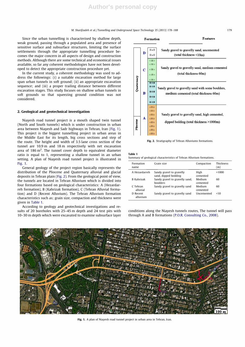
Niayesh road tunnel project is a mouth shaped twin tunnel(North and South tunnels) which is under construction in urbanarea between Niayesh and Sadr highways in Tehran, Iran (Fig. 1).This project is the biggest tunnelling project in urban areas inthe Middle East for its length, big cross sections and step ofthe route. The height and width of 3.5 lane cross section of thetunnel are 10.9 m and 18 m respectively with net excavationarea of 186 m2. The tunnel cover depth to equivalent diameterratio is equal to 1, representing a shallow tunnel in an urbansetting. A plan of Niayesh road tunnel project is illustrated inFig. 1.
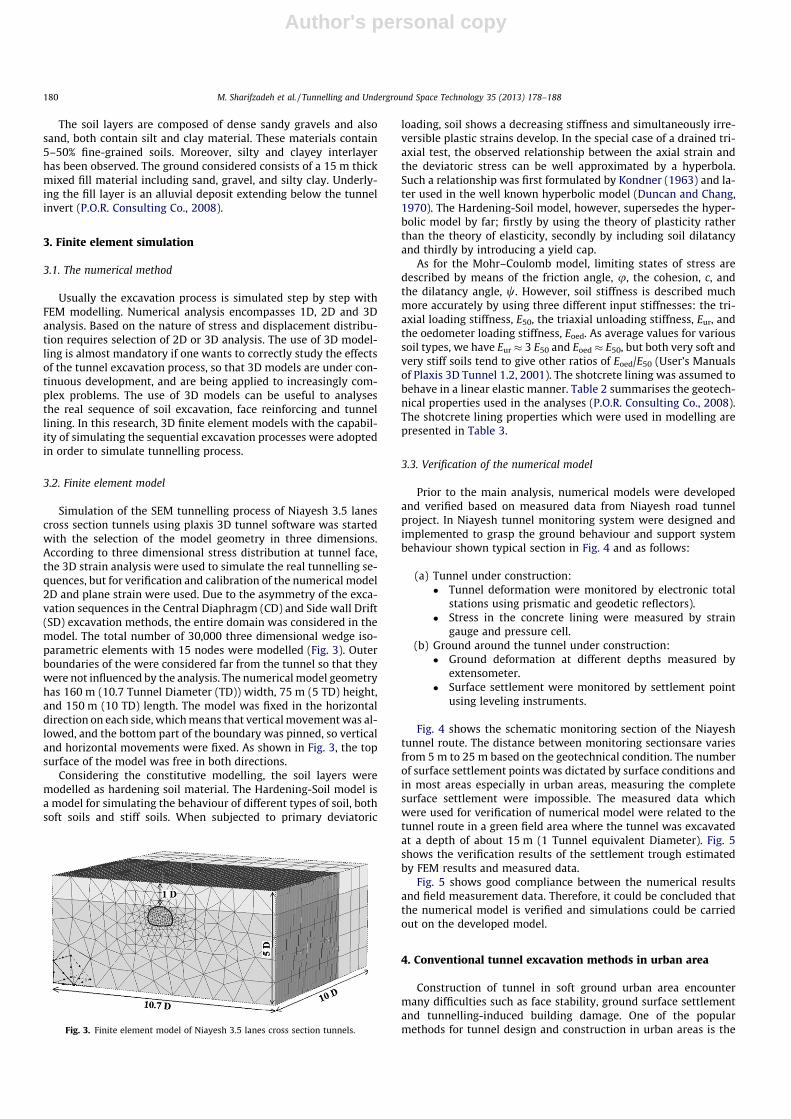
General geology of the project region basically represents thedistribution of the Pliocene and Quaternary alluvial and glacialdeposits in Tehran plain (Fig. 2). From the geological point of view,the tunnels are located in Tehran Alluvium which is divided intofour formations based on geological characteristics: A (Hezardar-reh formation), B (Kahrizak formation), C (Tehran Alluvial forma-tion) and D (Recent Alluvium). The Tehran Alluvium formationcharacteristics such as; grain size, compaction and thickness weregiven in Table 1.
According to geology and geotechnical investigations and re-sults of 20 boreholes with 25–45 m depth and 24 test pits with10–30 m depth which were excavated to examine subsurface layer
conditions along the Niayesh tunnels routes, The tunnel will passthrough A and B formations (P.O.R. Consulting Co., 2008).
Fig. 1. A plan of Niayesh road tunnel project in urban area in Tehran, Iran.
Fig. 2. Stratigraphy of Tehran Alluviums formations.
Table 1Summary of geological characteristics of Tehran Alluvium formations.
Formationname
Grain size Compaction Thickness(m)
A Hezardarreh Sandy gravel to gravellysand, dipped bedding
Highcemented
>1000
B Kahrizak Sandy gravel to gravelly sand,boulders
Mediumcemented
60
C Tehranalluvial
Sandy gravel to gravelly sand Mediumcemented
60
D Recentalluvium
Sandy gravel to gravelly sand Uncemented <10
M. Sharifzadeh et al. / Tunnelling and Underground Space Technology 35 (2013) 178–188 179
Author's personal copy
The soil layers are composed of dense sandy gravels and alsosand, both contain silt and clay material. These materials contain5–50% fine-grained soils. Moreover, silty and clayey interlayerhas been observed. The ground considered consists of a 15 m thickmixed fill material including sand, gravel, and silty clay. Underly-ing the fill layer is an alluvial deposit extending below the tunnelinvert (P.O.R. Consulting Co., 2008).
3. Finite element simulation
3.1. The numerical method
Usually the excavation process is simulated step by step withFEM modelling. Numerical analysis encompasses 1D, 2D and 3Danalysis. Based on the nature of stress and displacement distribu-tion requires selection of 2D or 3D analysis. The use of 3D model-ling is almost mandatory if one wants to correctly study the effectsof the tunnel excavation process, so that 3D models are under con-tinuous development, and are being applied to increasingly com-plex problems. The use of 3D models can be useful to analysesthe real sequence of soil excavation, face reinforcing and tunnellining. In this research, 3D finite element models with the capabil-ity of simulating the sequential excavation processes were adoptedin order to simulate tunnelling process.
3.2. Finite element model
Simulation of the SEM tunnelling process of Niayesh 3.5 lanescross section tunnels using plaxis 3D tunnel software was startedwith the selection of the model geometry in three dimensions.According to three dimensional stress distribution at tunnel face,the 3D strain analysis were used to simulate the real tunnelling se-quences, but for verification and calibration of the numerical model2D and plane strain were used. Due to the asymmetry of the exca-vation sequences in the Central Diaphragm (CD) and Side wall Drift(SD) excavation methods, the entire domain was considered in themodel. The total number of 30,000 three dimensional wedge iso-parametric elements with 15 nodes were modelled (Fig. 3). Outerboundaries of the were considered far from the tunnel so that theywere not influenced by the analysis. The numerical model geometryhas 160 m (10.7 Tunnel Diameter (TD)) width, 75 m (5 TD) height,and 150 m (10 TD) length. The model was fixed in the horizontaldirection on each side, which means that vertical movement was al-lowed, and the bottom part of the boundary was pinned, so verticaland horizontal movements were fixed. As shown in Fig. 3, the topsurface of the model was free in both directions.
Considering the constitutive modelling, the soil layers weremodelled as hardening soil material. The Hardening-Soil model isa model for simulating the behaviour of different types of soil, bothsoft soils and stiff soils. When subjected to primary deviatoric
loading, soil shows a decreasing stiffness and simultaneously irre-versible plastic strains develop. In the special case of a drained tri-axial test, the observed relationship between the axial strain andthe deviatoric stress can be well approximated by a hyperbola.Such a relationship was first formulated by Kondner (1963) and la-ter used in the well known hyperbolic model (Duncan and Chang,1970). The Hardening-Soil model, however, supersedes the hyper-bolic model by far; firstly by using the theory of plasticity ratherthan the theory of elasticity, secondly by including soil dilatancyand thirdly by introducing a yield cap.
As for the Mohr–Coulomb model, limiting states of stress aredescribed by means of the friction angle, u, the cohesion, c, andthe dilatancy angle, w. However, soil stiffness is described muchmore accurately by using three different input stiffnesses: the tri-axial loading stiffness, E50, the triaxial unloading stiffness, Eur, andthe oedometer loading stiffness, Eoed. As average values for varioussoil types, we have Eur � 3 E50 and Eoed � E50, but both very soft andvery stiff soils tend to give other ratios of Eoed/E50 (User’s Manualsof Plaxis 3D Tunnel 1.2, 2001). The shotcrete lining was assumed tobehave in a linear elastic manner. Table 2 summarises the geotech-nical properties used in the analyses (P.O.R. Consulting Co., 2008).The shotcrete lining properties which were used in modelling arepresented in Table 3.
3.3. Verification of the numerical model
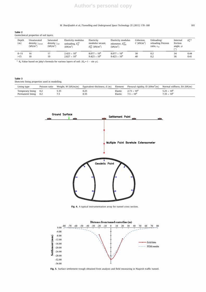
Prior to the main analysis, numerical models were developedand verified based on measured data from Niayesh road tunnelproject. In Niayesh tunnel monitoring system were designed andimplemented to grasp the ground behaviour and support systembehaviour shown typical section in Fig. 4 and as follows:
(a) Tunnel under construction:� Tunnel deformation were monitored by electronic total
stations using prismatic and geodetic reflectors).� Stress in the concrete lining were measured by strain
gauge and pressure cell.(b) Ground around the tunnel under construction:� Ground deformation at different depths measured by
extensometer.� Surface settlement were monitored by settlement point
using leveling instruments.
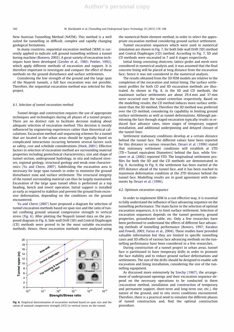
Fig. 4 shows the schematic monitoring section of the Niayeshtunnel route. The distance between monitoring sectionsare variesfrom 5 m to 25 m based on the geotechnical condition. The numberof surface settlement points was dictated by surface conditions andin most areas especially in urban areas, measuring the completesurface settlement were impossible. The measured data whichwere used for verification of numerical model were related to thetunnel route in a green field area where the tunnel was excavatedat a depth of about 15 m (1 Tunnel equivalent Diameter). Fig. 5shows the verification results of the settlement trough estimatedby FEM results and measured data.
Fig. 5 shows good compliance between the numerical resultsand field measurement data. Therefore, it could be concluded thatthe numerical model is verified and simulations could be carriedout on the developed model.
4. Conventional tunnel excavation methods in urban area
Construction of tunnel in soft ground urban area encountermany difficulties such as face stability, ground surface settlementand tunnelling-induced building damage. One of the popularmethods for tunnel design and construction in urban areas is theFig. 3. Finite element model of Niayesh 3.5 lanes cross section tunnels.
180 M. Sharifzadeh et al. / Tunnelling and Underground Space Technology 35 (2013) 178–188
Author's personal copy
Table 2Geotechnical properties of soil layers.
Depth(m)
Unsaturateddensity cunsat
(kN/m3)
Saturateddensity csat
(kN/m3)
Elasticity modulus
unloading, Erefur
(kN/m2)
Elasticitymodulus secant,
Eref50 (kN/m2)
Elasticity modulus
edometer, ErefOed
(kN/m2)
Cohesion,C (kN/m2)
Unloading/reloading Poissonratio, tur
Internalfrictionangle, u(�)
Knc0
a
0–15 16 17 2.423 � 105 8.077 � 104 8.077 � 104 30 0.2 34 0.44>15 18 19 2.827 � 105 9.423 � 104 9.423 � 104 40 0.2 36 0.41
a K0 Value based on Jaky’s formula for various layers of soil: (K0 = 1 � sin u).
Table 3Shotcrete lining properties used in modelling.
Lining type Poisson ratio Weight, W (kN/m/m) Equivalent thickness, d (m) Element Flexural rigidity, EI (kNm2/m) Normal stiffness, EA (kN/m)
Temporary lining 0.2 5.35 0.25 Elastic 2.73 � 104 5.25 � 106
Permanent lining 0.2 7.5 0.35 Elastic 7.5 � 104 7.35 � 106
Fig. 4. A typical instrumentation array for tunnel cross section.
Fig. 5. Surface settlement trough obtained from analysis and field measuring in Niayesh traffic tunnel.
M. Sharifzadeh et al. / Tunnelling and Underground Space Technology 35 (2013) 178–188 181
Author's personal copy
New Austrian Tunnelling Method (NATM). This method is a wellsuited for tunnelling in difficult, complex and rapidly changinggeological formations.
In many countries, sequential excavation method (SEM) is cur-rently applied to indicate soft ground tunnelling without a tunnelboring machine (Romero, 2002). A great variety of excavation tech-niques have been developed (Geisler et al., 1985; Pottler, 1992),which apply different methods of excavation and support. It istherefore important to investigate and compare the effect of thesemethods on the ground disturbance and surface settlements.
Considering the low strength of the ground and the large spanof the Niayesh tunnels, a full face excavation was not possible.Therefore, the sequential excavation method was selected for thisproject.
4.1. Selection of tunnel excavation method
Tunnel design and construction requires the use of appropriatetechniques and technologies during all phases of a tunnel project.There are no distinct rule to facilitate decision making aboutadequate selection of excavation method. This decision is mostlyinfluenced by engineering experiences rather than theoretical cal-culations. Excavation method and sequencing schemes for a tunnelthat are located in the urban areas should be typically based oncomplicated interactions occurring between several factors suchas safety, cost and schedule considerations (Hoek, 2001). Effectivefactors in selection of excavation method are surrounding materialproperties including geotechnical characteristics, size and shape oftunnel section, underground hydrology, in situ and induced stres-ses, regional geology, structural geology and weak zone character-istics (Yu and Chern, 2007). Subdividing the excavation area isnecessary for large span tunnels in order to minimise the grounddisturbance zone and surface settlement. The structural integrityof the tunnel surrounding material can thus be largely maintained.Excavation of the large span tunnel often is performed as a topheading, bench and invert operation. Initial support is installedas early as required to stabilize and prevent the ground from exces-sive deformation, depending on the conditions on the groundencountered.
Yu and Chern (2007) have proposed a diagram for selection oftunnel excavation methods based on span size and the ratio of tun-nel confining ground uniaxial compressive strength to verticalstress (Fig. 6). After plotting the Niayesh tunnel data on the pro-posed diagram in Fig. 6, Side wall Drift (SD) and Central Diaphragm(CD) methods were proved to be the most suitable excavationmethods. Hence, these excavation methods were analysed using
the numerical finite element method, in order to select the appro-priate excavation method considering ground surface settlement.
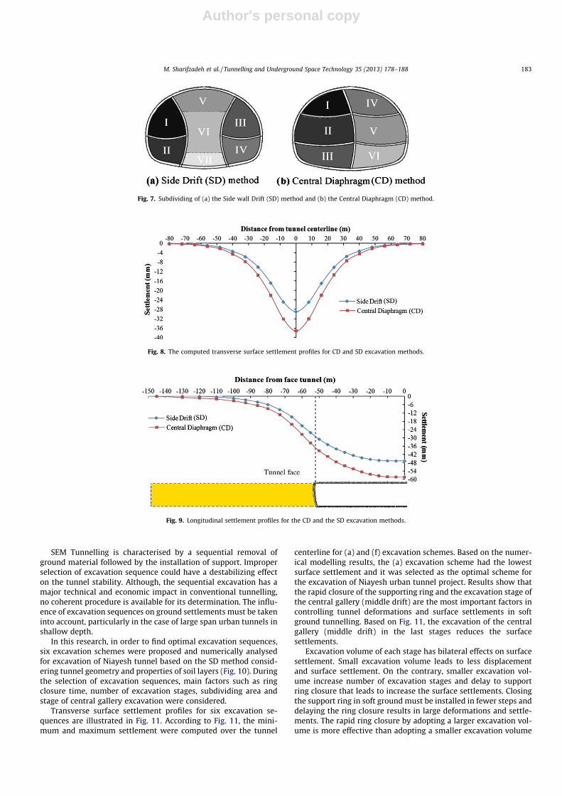
Tunnel excavation sequences which were used in numericalsimulation are shown in Fig. 7, for both Side wall Drift (SD) methodand Central Diaphragm (CD) method. According to Fig. 7, SD andCD methods were excavated in 7 and 6 stages respectively.
Initial lining consisting shotcrete, lattice girder and mesh wereconsidered in numerical analysis and, it was assumed that the finalconcrete lining will be placed at long distance from the excavationface; hence it was not considered in the numerical analysis.
The results obtained from the 3D FEM models are relative to thecompletion of the excavation and initial lining. The surface settle-ment profiles for both CD and SD excavation methods are illus-trated. As shown in Fig. 8, in the SD and CD methods, themaximum surface settlements are about 29.4 mm and 37 mmwere occurred over the tunnel centerline respectively. Based onthe modelling results, the CD method induces more surface settle-ment than the SD method. Therefore the SD method was preferredover the CD method, considering its capability in limiting groundsurface settlements as well as tunnel deformations. Although par-titioning the face through staged excavation typically results in re-duced face advance rates, more stages of temporary supportinstallation, and additional underpinning and delayed closure ofthe tunnel liner.
Settlement stationary conditions develop at a certain distancebehind the tunnel face. The different values have been reportedfor this distance in various researches. Desari et al. (1996) statedthat stationary settlement conditions will establish at 2TD(TD = Tunnel equivalent Diameters) behind the face, while Ver-meer et al. (2002) reported 5TD. The longitudinal settlement pro-files for both the SD and the CD methods are demonstrated inFig. 9. According to Fig. 9, the settlement has been started at the4TD distance ahead of the tunnel face, and it has been reached tomaximum deformation condition at the 2TD distance behind thetunnel face. Modelling results are in good agreement with state-ments by Desari et al. (1996).
4.2. Optimum excavation sequence
In order to implement SEM in a cost effective way, it is essentialto fully understand the influence of face advancing sequence on thetunnelling performance. The main factor in the selection of optimalexcavation sequences, it is to limit surface settlement. Selection ofexcavation sequences depends on the tunnel geometry, groundproperties, groundwater table, etc. Only a few researches havebeen performed to understand the effects of different face advanc-ing methods of tunnelling performance (Bowers, 1997; Karakusand Fowell, 2003; Farias et al., 2004). These studies have providedvaluable information but they are limited to specific tunnellingcases and 3D effects of various face advancing methods on the tun-nelling performance have been considered in a few researches.
During construction of a tunnel project in urban areas, tunnelface is partitioned to have temporary drifts in order to promotethe face stability and to reduce ground surface deformations andsettlements. The size of the drifts should be designed to enable safeexcavation and lining installation, considering the size of the tun-nelling equipment.
As discussed more extensively by Szechy (1967), the arrange-ment of underground openings and their excavation sequence de-pend on the necessary operations to be conducted in them(excavation method, installation and construction of temporaryand permanent support, short-term and long-term use, etc.), thenature of the ground, and in situ stress conditions encountered.Therefore, there is a practical need to simulate the different phasesof tunnel construction and, find the optimal constructionprocedure.
Fig. 6. Empirical determination of excavation method based on span size and theration of uniaxial compressive strength (UCS) to vertical stress on the tunnel.
182 M. Sharifzadeh et al. / Tunnelling and Underground Space Technology 35 (2013) 178–188
Author's personal copy
SEM Tunnelling is characterised by a sequential removal ofground material followed by the installation of support. Improperselection of excavation sequence could have a destabilizing effecton the tunnel stability. Although, the sequential excavation has amajor technical and economic impact in conventional tunnelling,no coherent procedure is available for its determination. The influ-ence of excavation sequences on ground settlements must be takeninto account, particularly in the case of large span urban tunnels inshallow depth.
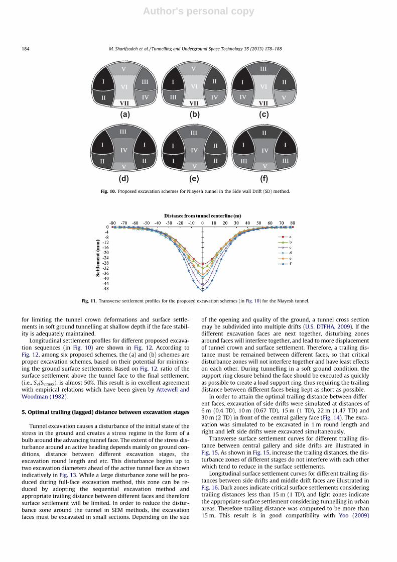
In this research, in order to find optimal excavation sequences,six excavation schemes were proposed and numerically analysedfor excavation of Niayesh tunnel based on the SD method consid-ering tunnel geometry and properties of soil layers (Fig. 10). Duringthe selection of excavation sequences, main factors such as ringclosure time, number of excavation stages, subdividing area andstage of central gallery excavation were considered.
Transverse surface settlement profiles for six excavation se-quences are illustrated in Fig. 11. According to Fig. 11, the mini-mum and maximum settlement were computed over the tunnel
centerline for (a) and (f) excavation schemes. Based on the numer-ical modelling results, the (a) excavation scheme had the lowestsurface settlement and it was selected as the optimal scheme forthe excavation of Niayesh urban tunnel project. Results show thatthe rapid closure of the supporting ring and the excavation stage ofthe central gallery (middle drift) are the most important factors incontrolling tunnel deformations and surface settlements in softground tunnelling. Based on Fig. 11, the excavation of the centralgallery (middle drift) in the last stages reduces the surfacesettlements.
Excavation volume of each stage has bilateral effects on surfacesettlement. Small excavation volume leads to less displacementand surface settlement. On the contrary, smaller excavation vol-ume increase number of excavation stages and delay to supportring closure that leads to increase the surface settlements. Closingthe support ring in soft ground must be installed in fewer steps anddelaying the ring closure results in large deformations and settle-ments. The rapid ring closure by adopting a larger excavation vol-ume is more effective than adopting a smaller excavation volume
Fig. 7. Subdividing of (a) the Side wall Drift (SD) method and (b) the Central Diaphragm (CD) method.
Fig. 8. The computed transverse surface settlement profiles for CD and SD excavation methods.
Fig. 9. Longitudinal settlement profiles for the CD and the SD excavation methods.
M. Sharifzadeh et al. / Tunnelling and Underground Space Technology 35 (2013) 178–188 183
Author's personal copy
for limiting the tunnel crown deformations and surface settle-ments in soft ground tunnelling at shallow depth if the face stabil-ity is adequately maintained.
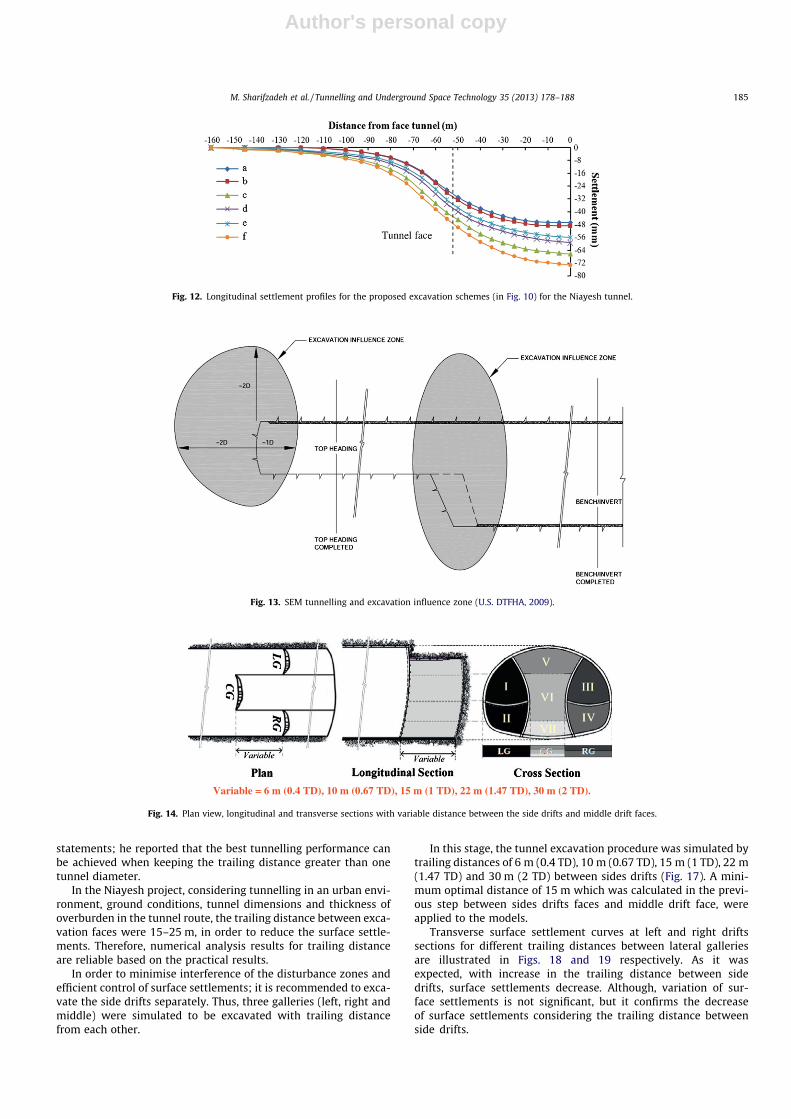
Longitudinal settlement profiles for different proposed excava-tion sequences (in Fig. 10) are shown in Fig. 12. According toFig. 12, among six proposed schemes, the (a) and (b) schemes areproper excavation schemes, based on their potential for minimis-ing the ground surface settlements. Based on Fig. 12, ratio of thesurface settlement above the tunnel face to the final settlement,(i.e., Sv/Sv,max), is almost 50%. This result is in excellent agreementwith empirical relations which have been given by Attewell andWoodman (1982).
5. Optimal trailing (lagged) distance between excavation stages
Tunnel excavation causes a disturbance of the initial state of thestress in the ground and creates a stress regime in the form of abulb around the advancing tunnel face. The extent of the stress dis-turbance around an active heading depends mainly on ground con-ditions, distance between different excavation stages, theexcavation round length and etc. This disturbance begins up totwo excavation diameters ahead of the active tunnel face as shownindicatively in Fig. 13. While a large disturbance zone will be pro-duced during full-face excavation method, this zone can be re-duced by adopting the sequential excavation method andappropriate trailing distance between different faces and thereforesurface settlement will be limited. In order to reduce the distur-bance zone around the tunnel in SEM methods, the excavationfaces must be excavated in small sections. Depending on the size
of the opening and quality of the ground, a tunnel cross sectionmay be subdivided into multiple drifts (U.S. DTFHA, 2009). If thedifferent excavation faces are next together, disturbing zonesaround faces will interfere together, and lead to more displacementof tunnel crown and surface settlement. Therefore, a trailing dis-tance must be remained between different faces, so that criticaldisturbance zones will not interfere together and have least effectson each other. During tunnelling in a soft ground condition, thesupport ring closure behind the face should be executed as quicklyas possible to create a load support ring, thus requiring the trailingdistance between different faces being kept as short as possible.
In order to attain the optimal trailing distance between differ-ent faces, excavation of side drifts were simulated at distances of6 m (0.4 TD), 10 m (0.67 TD), 15 m (1 TD), 22 m (1.47 TD) and30 m (2 TD) in front of the central gallery face (Fig. 14). The exca-vation was simulated to be excavated in 1 m round length andright and left side drifts were excavated simultaneously.
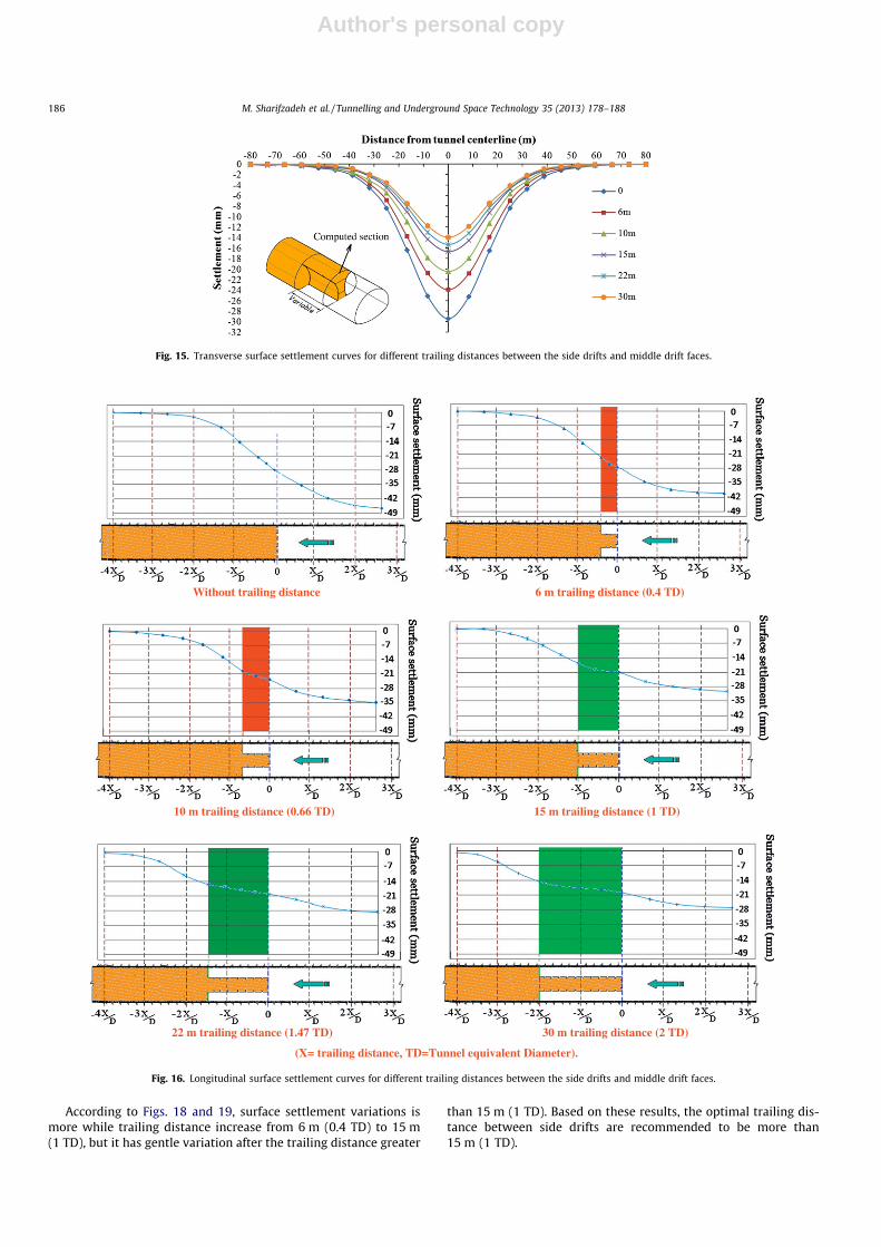
Transverse surface settlement curves for different trailing dis-tance between central gallery and side drifts are illustrated inFig. 15. As shown in Fig. 15, increase the trailing distances, the dis-turbance zones of different stages do not interfere with each otherwhich tend to reduce in the surface settlements.
Longitudinal surface settlement curves for different trailing dis-tances between side drifts and middle drift faces are illustrated inFig. 16. Dark zones indicate critical surface settlements consideringtrailing distances less than 15 m (1 TD), and light zones indicatethe appropriate surface settlement considering tunnelling in urbanareas. Therefore trailing distance was computed to be more than15 m. This result is in good compatibility with Yoo (2009)
VII VII VII
Fig. 10. Proposed excavation schemes for Niayesh tunnel in the Side wall Drift (SD) method.
Fig. 11. Transverse settlement profiles for the proposed excavation schemes (in Fig. 10) for the Niayesh tunnel.
184 M. Sharifzadeh et al. / Tunnelling and Underground Space Technology 35 (2013) 178–188
Author's personal copy
statements; he reported that the best tunnelling performance canbe achieved when keeping the trailing distance greater than onetunnel diameter.
In the Niayesh project, considering tunnelling in an urban envi-ronment, ground conditions, tunnel dimensions and thickness ofoverburden in the tunnel route, the trailing distance between exca-vation faces were 15–25 m, in order to reduce the surface settle-ments. Therefore, numerical analysis results for trailing distanceare reliable based on the practical results.
In order to minimise interference of the disturbance zones andefficient control of surface settlements; it is recommended to exca-vate the side drifts separately. Thus, three galleries (left, right andmiddle) were simulated to be excavated with trailing distancefrom each other.
In this stage, the tunnel excavation procedure was simulated bytrailing distances of 6 m (0.4 TD), 10 m (0.67 TD), 15 m (1 TD), 22 m(1.47 TD) and 30 m (2 TD) between sides drifts (Fig. 17). A mini-mum optimal distance of 15 m which was calculated in the previ-ous step between sides drifts faces and middle drift face, wereapplied to the models.
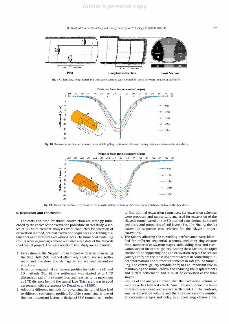
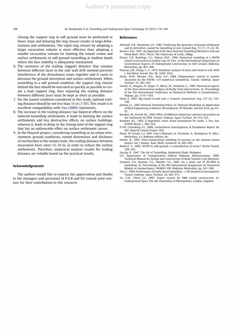
Transverse surface settlement curves at left and right driftssections for different trailing distances between lateral galleriesare illustrated in Figs. 18 and 19 respectively. As it wasexpected, with increase in the trailing distance between sidedrifts, surface settlements decrease. Although, variation of sur-face settlements is not significant, but it confirms the decreaseof surface settlements considering the trailing distance betweenside drifts.
Fig. 12. Longitudinal settlement profiles for the proposed excavation schemes (in Fig. 10) for the Niayesh tunnel.
Fig. 13. SEM tunnelling and excavation influence zone (U.S. DTFHA, 2009).
Variable = 6 m (0.4 TD), 10 m (0.67 TD), 15 m (1 TD), 22 m (1.47 TD), 30 m (2 TD).
Fig. 14. Plan view, longitudinal and transverse sections with variable distance between the side drifts and middle drift faces.
M. Sharifzadeh et al. / Tunnelling and Underground Space Technology 35 (2013) 178–188 185
Author's personal copy
According to Figs. 18 and 19, surface settlement variations ismore while trailing distance increase from 6 m (0.4 TD) to 15 m(1 TD), but it has gentle variation after the trailing distance greater
than 15 m (1 TD). Based on these results, the optimal trailing dis-tance between side drifts are recommended to be more than15 m (1 TD).
Fig. 15. Transverse surface settlement curves for different trailing distances between the side drifts and middle drift faces.
Without trailing distance 6 m trailing distance (0.4 TD)
10 m trailing distance (0.66 TD) 15 m trailing distance (1 TD)
22 m trailing distance (1.47 TD) 30 m trailing distance (2 TD)
(X= trailing distance, TD=Tunnel equivalent Diameter).
Fig. 16. Longitudinal surface settlement curves for different trailing distances between the side drifts and middle drift faces.
186 M. Sharifzadeh et al. / Tunnelling and Underground Space Technology 35 (2013) 178–188
Author's personal copy
6. Discussion and conclusion
The costs and time for tunnel construction are strongly influ-enced by the choice of the excavation procedure. In this study, a ser-ies of 3D finite element analyses were conducted for selection ofexcavation method, optimal excavation sequences and trailing dis-tance between different excavations faces. The numerical modellingresults were in good agreement with measured data of the Niayeshroad tunnel project. The main results of this study are as follows:
1. Excavation of the Niayesh urban tunnel with large span usingthe Side Drift (SD) method effectively control surface settle-ment and therefore low damage to surface and subsurfacestructures.
2. Based on longitudinal settlement profiles for both the CD andSD methods (Fig. 9), the settlement was started at a 4 TDdistance ahead of the tunnel face, and reaches to its maximumat 2 TD distance behind the tunnel face. This result was in goodagreement with statements by Desari et al. (1996).
3. Adopting different methods for advancing the tunnel face leadto different settlement profiles. Suitable sequencing is one ofthe most important factors in design of SEM tunnelling. In order
to find optimal excavation sequences, six excavation schemeswere proposed and numerically analysed for excavation of theNiayesh tunnel based on the SD method considering the tunnelgeometry and properties of soil layers (Fig. 10). Finally, the (a)excavation sequence was selected for the Niayesh projectexcavation.
4. The factors affecting the tunnelling performance were identi-fied for different sequential schemes, including ring closuretime, number of excavation stages, subdividing area, and exca-vation step of the central gallery. Among these factors, the rapidclosure of the supporting ring and excavation step of the centralgallery (drift) are the most important factors in controlling tun-nel deformations and surface settlements in soft ground tunnel-ling. The central gallery (middle drift) has an important role inmaintaining the tunnel crown and reducing the displacementsand surface settlement, and it must be excavated at the finalstages.
5. Results of the analysis showed that the excavation volume ofeach stage has bilateral effects. Small excavation volume leadsto less displacement and surface settlement. On the contrary,smaller excavation volume and therefore increase the numberof excavation stages and delay in support ring closure time.
Fig. 17. Plan view, longitudinal and transverse sections with variable distance between the face of side drifts.
Fig. 18. Transverse surface settlement curves at left gallery section for different trailing distances between the side drifts.
Fig. 19. Transverse surface settlement curves at right gallery section for different trailing distances between the side drifts.
M. Sharifzadeh et al. / Tunnelling and Underground Space Technology 35 (2013) 178–188 187
Author's personal copy
Closing the support ring in soft ground must be performed infewer steps and delaying the ring closure results in large defor-mations and settlements. The rapid ring closure by adopting alarger excavation volume is more effective than adopting asmaller excavation volume for limiting the tunnel crown andsurface settlements in soft ground tunnelling at shallow depthwhere the face stability is adequately maintained.
6. The existence of the trailing (lagged) distance that remainsbetween different faces in the side wall drift method preventsinterference of the disturbance zones together and it cause todecrease the ground movement and surface settlements. Whentunnelling in a soft ground condition, the support ring closurebehind the face should be executed as quickly as possible to cre-ate a load support ring, thus requiring the trailing distancebetween different faces must be kept as short as possible.
7. For the tunnel condition considered in this study, optimal trail-ing distance should be not less than 15 m (1 TD). This result is inexcellent compatibility with Yoo (2009) statements.
8. The increase in the trailing distance has bilateral effects on theinduced-tunnelling settlements. It leads to limiting the surfacesettlements and less destructive effects on surface buildings,whereas it, leads to delay in the closing time of the support ringthat has an unfavorable effect on surface settlement curves.
9. In the Niayesh project, considering tunnelling in an urban envi-ronment, ground conditions, tunnel dimensions and thicknessof overburden in the tunnel route, the trailing distance betweenexcavation faces were 15–25 m, in order to reduce the surfacesettlements. Therefore, numerical analysis results for trailingdistance are reliable based on the practical results.
Acknowledgements
The authors would like to express the appreciation and thanksto the managers and personnel of P.O.R and D2 consult joint ven-ture for their contribution to this research.
References
Attewell, P.B., Woodman, J.P., 1982. Predicting the dynamics of ground settlementand its derivitives caused by tunnelling in soil. Ground Eng. 15 (7), 13–22, 36.
Bowers, K.H., 1997. An Appraisal of the New Austrian Tunnelling Method in Soil andWeak Rock. Ph.D. Thesis, The University of Leeds, 240pp.
Desari, G.R., Rawlings, C.G., Bolton, M.D., 1996. Numerical modeling of a NATMtunnel construction in London clay. In: Proc. of the International Symposium onGeotechnical Aspects of Underground Construction in Soft Ground. Balkema,Rotterdam, pp. 491–496.
Duncan, J.M., Chang, C.-Y., 1970. Nonlinear analysis of stress and strain in soil. ASCEJ. Soil Mech. Found. Div. 96, 1629–1653.
Farias, M.M., Moraes, A.H., Assis, A.P., 2004. Displacement control in tunnelsexcavated by the NATM: 3-D numerical simulations. Tunnel. Undergr. SpaceTechnol. 19, 283–293.
Geisler, H., Wagner, H., Zieger, O., Mertz, W., Swoboda, G., 1985. Theoretical aspectsof the three dimensional analysis of finally lined intersections. In: Proceedingsof the 5th International Conference on Numerical Methods in Geomechanics,Nagoya, pp. 1175–1183.
Hoek, E., 2001. Big tunnel in bad rock. J. Geotech. Geoenviron. Eng. 127 (9), 726–740.
Jethwa, J.L., 2001 National Tunnelling Policy. In: National Workshop on Applicationof Rock Engineering in Nation’s Development. IIT Roorkie: Ind Inst Tech, pp. 63–81.
Karakus, M., Fowell, R.J., 2003. Effect of different tunnel face advance excavation onthe settlement by FEM. Tunnel. Undergr. Space Technol. 18, 513–523.
Kondner, R.L., 1963. A hyperbolic stress strain formulation for sands. 2. Pan. Am.ICOSFE Brazil 1, 289–324.
P.O.R. Consulting Co., 2008. Geotechnical Investigations & Foundation Report for601 Niayesh Tunnel Project. 602.
Plaxis 3D Tunnel 1.2, 2001. User’s Manuals. In: Vermmer, A., Brinkgreve, R. (Eds.),Rotterdam, a.a. Balkema edition, Inc.
Pottler, R., 1992. Three-dimensional modeling of junction at the channel tunnelproject. Int J. Numer. Anal. Meth. Geomech 16, 683–695.
Romero, V., 2002. NATM in soft-ground: a contradiction of terms? World Tunnel,338–343.
Szechy, K., 1967. The Art of Tunnelling. Akademiai Kiado, Budapest.U.S. Department of Transportation Federal Highway Administration, 2009.
Technical Manual for Design and Construction of Road Tunnels Civil Elements.Vermeer, P.A., Bonnier, P.G., Maoller, S.C., 2002. On a smart use of 3D-FEM in
tunnelling. In: Proceedings of the 8th International Symposium on NumericalModels in Geomechanics. NUMOG VIII. Balkema, Rotterdam, pp. 361–366.
Yoo, C., 2009. Performance of multi-faced tunnelling – a 3D numerical investigation.Tunnel. Undergr. Space Technol. 24, 562–573.
Yu, C.W., Chern, J.C., 2007. Expert system for D&B tunnel construction. In:Underground Space The 4th Dimension of Metropolises, London, England.
188 M. Sharifzadeh et al. / Tunnelling and Underground Space Technology 35 (2013) 178–188