the effect of robot kinematics on the coating thickness uniformity
TRANSCRIPT

The Effect of Robot Kinematicson the Coating Thickness Uniformity
D. Fang, S. Deng, H. Liao, and C. Coddet
(Submitted July 27, 2009; in revised form October 18, 2009)
The torch speed is one of the most important operating parameters in thermal spraying. Generally, inorder to keep a uniform coating thickness, the movement of the torch should be constant. Nevertheless,when the torch follows a large trajectory angle, the torch speed will decrease significantly, which leads toan irregular coating thickness. This phenomenon is caused by the weight of different devices fixed on therobot and the combination of the robot�s six axes. It is therefore necessary to optimize robot kinematicsbehaviors in this case. In this paper, the works concentrate mainly on the relationship between the robotkinematics property and the coating quality to find an adequate model for the torch speed optimization.An add-in program based on RobotStudio� (ABB, Sweden) is developed to determine and optimize thespray trajectory. The optimal trajectory was verified by both the simulations and the experiments.
Keywords coating quality, optimize spray trajectory, robotkinematics, RobotStudio�, torch speed
1. Introduction
High-accuracy robot systems are widely used in mod-ern thermal spray applications in recent years (Ref 1).When using a robot in thermal spraying, the trajectorygeneration represents an important part of the work. Thegeneration of robot trajectory on 2D surface in thermalspraying is traditionally made by methods such as point-by-point or teaching-playback. But the demand for coat-ing on 3D surface has increased over the last few years. Itrequires hundreds of points in the trajectory and differentorientation for each point, so it is very difficult to createsuch a trajectory by manual point-by-point programmingmethod (Ref 2, 3). With the development of the robotics,the robot manufacturers provide software for off-lineprogramming, such as RobotStudio�, which is a simula-tion and off-line programming software of ABB Com-pany. A virtual workshop can be elaborated and therobot program can be prepared and simulated withRobotStudio�. The turning status of 6 axes can be easilyobtained while simulating the robot movement. This helpsus to evaluate robot kinematics behavior during thespraying process which is used as the basis of optimization.In this paper, an ABB robot and the off-line programmingsoftware RobotStudio� will be considered.
There are some important operating parameters inthermal spraying, for example, the torch speed, the standoff distance, spray angle, etc. The torch speed is one of the
most important operating parameters in thermal spraying.In order to ensure the required quality of coatings, themovement of torch should be constant and the spraydirection should be as close to normal as possible to thecoating surface. However, when the torch follows a tra-jectory on a curved workpiece, if there is a large change ofthe torch orientation, the torch speed will be obviouslydecreased. This phenomenon can be explained by anuncoordinated combination of robot�s six axes. Moreover,the movements that require a great torque in the robots�axes will not be correctly implemented due to sometechnical limitations associated with the servos. Thekinematics behavior of the robot is thus of prime impor-tance in the program execution, so it is necessary tooptimize robot kinematics behaviors in this case (Ref 4).In this study, several methods will be proposed to optimizethe robot movement in order to keep a uniform coatingthickness.
2. Problems and Optimized Methods
As we know, in thermal spraying, the coating proper-ties such as coating structure and surface profile (e.g.coating thickness) are highly influenced by the torchspeed. Generally, in order to keep the coating thicknessuniformity, the movement of the torch should be constant.But in certain case for example, to coat the sample shownin Fig. 1(a), the robot could not keep the speed as itshould be.
In this study, a 1 mm thick stainless steel sheet with anangle 90� as shown in Fig. 1(a) was used as the substrate inour simulations and experiments. According to our pre-vious tests, when the torch follows a trajectory whichcontains a large angle, the torch has to change its orien-tation rapidly. In this condition, it is not always possiblefor the robot to keep the torch speed, which leads to an
D. Fang, S. Deng, H. Liao, and C. Coddet, LERMPS, Universitede Technologie de Belfort-Montbeliard, Site de Sevenans, 90010Belfort Cedex, France. Contact e-mail: [email protected].
JTTEE5 19:796–804
DOI: 10.1007/s11666-010-9470-7
1059-9630/$19.00 � ASM International
796—Volume 19(4) June 2010 Journal of Thermal Spray Technology
Peer
Revie
wed

irregular coating thickness. This is probably caused by tworeasons.
The first is perhaps that the different devices fixed onthe robot arm have a big inertia, which can prevent therobot arm from respecting the designed speed. It meansthe torch speed cannot always reach the planned value.The weight of all the devices fixed on the robot includingthe torch, the pipes and the cables were measured, whichis about 9.7 kg in total in our experiments.
The second one is that a rapid change between linearand curved trajectory leads to a high individual axisacceleration, which can result in a strong vibration ofrobot arms and then deviate the torch trajectory. Asshown in Fig. 1(b), there are many spray points in thetrajectory which was created in RobotStudio�, the ori-entation of each spray point is different, blue color rep-resents z-axis, green color represents y-axis, and red colorrepresents x-axis. From A to B the distance is about55 mm, and the planned torch speed is 500 mm/s, so therobot should take 0.11 s to pass these two points. Thatmeans that it must turn 90� in 0.11 s when combining all6 axes. This should exceed the performance limit of therobot.
According to our experience, the influences of torchand cable weights on torch speed are small and it is dif-ficult to solve this problem. Anyway it will be verified laterby our experiments. Thus, our works will focus on esti-mating the effects from the second reason. Two strategiesare proposed for optimizing the kinematics behavior inthis paper in order to solve this problem.
2.1 Optimizing the Spray Trajectoryby Changing Torch Setup
Based on the robot kinematics theory, the action of therobot is a combination of six individual axes: any complexaction such as moving the torch from one point to anotherpoint can be decomposed in a series of axis movements(Ref 5). The position of the robot and its movements arealways related to its tool coordinate system, i.e. the ToolCenter Point (TCP) and tool orientation. TCP is definedas the impact point of material jet on the substrate in
thermal spraying, which should scan all the surface ofworkpiece during the process (Ref 6). In fact, in therobot controller system, the speed parameter is defined asTCP speed which decides the torch speed in thermalspraying. In this paper, the TCP speed obtained fromRobotStudio� is called simulated TCP speed, and theTCP speed collected from robot controller is called realTCP speed. Different torch setup system including clampposition, torch direction, etc., will change TCP definitiondirectly. For the same trajectories, different TCP defini-tions will bring different load distributions to six axes.That means a little change of TCP definition will changethe relative movements of six axes as well as robotkinematics behaviors.
To explore the effect of the proposal mentionedabove, two torch setup systems were tested. Figure 2(a)shows a conventional torch setup and Fig. 2(b) shows thesimulation in RobotStudio�. The software RobotStudio�allows simulating the process sequence. It is possibleto test the robot movement collisions, the TCP speed,the movements of six axes and other problems duringthe simulation. For a given workpiece, the spray trajec-tory is created by the following two steps. In the firststep, the way according to which the Computer AidedDesign (CAD) imported data or the combination ofsome simple shapes is used for modeling the workpiecein RobotStudio�. In the second step, Thermal SprayToolkit (TST) (Ref 7) is used to auto-generate thespray trajectory as described in Fig. 1(b). The orienta-tion of each point is perpendicularly positioned to theworkpiece surface. Here, a six degree of freedom ABBrobot (IRB4400_45) was used in our simulations andexperiments.
The movements of each axis recorded as ‘‘rotationangle’’ while the robot realizes the spray program for onepass by using conventional torch setup in simulation areshown in Fig. 3. The angular velocities of axes corre-sponding to every sampling point by using the conven-tional torch setup are calculated from Fig. 3 and shownin Fig. 4.
For a normal six-axis robot, the performance of eachservo is different. Table 1 describes the maximum angular
Fig. 1 (a) Real workpiece with a large angle and (b) trajectory with a large angle
Journal of Thermal Spray Technology Volume 19(4) June 2010—797
Peer
Revie
wed

velocity of each axis and the working range of each axis inrotation for an ABB Robot IRB 4400-45.
As shown in Fig. 4 and Table 1, axes 4, 5 and 6 wereloaded with the biggest movement of the torch, axis 4reached its performance limit in the action and axis 5 isclose to its maximum. So the purpose of optimization is toreorientate torch setup in order to combine the move-ments of axes 4 and 5 into axis 6 which is more prefermentthan the other axes as shown in Table 1. It can be obvi-ously noticed that the biggest orientation changes hap-pened in the plane X-Y, so the wrist plane of axis 6 shouldbe superposed in X-Y for this purpose.
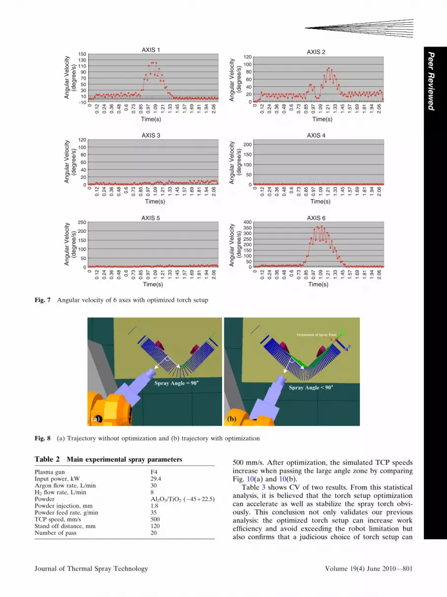
Figure 5 shows the optimized torch setup and the samesimulation with optimized torch setup. Figure 6 shows themovement of each axis after optimization. Figure 7 showsthe calculated angular velocities of six axes correspondingto every sampling point after optimization. As shown inFig. 7, the angular velocity increases slightly for axes 1, 2and 3; however, the angular velocity decreases greatly foraxes 4 and 5. It is clear that axis 6 was distributed moremovement load than the other axes. As mentioned earlier,axis 6 is the most flexible axis in all axes, so it is reasonableto let axis 6 assume the well-proportioned task. And thiskind of movement load distribution should improve TCPspeed.
For a deeper investigation, a comparison parametercalled Motion Quantity (MQ) was defined for analyzingthe robot work efficiency. MQ is the summation of the
rotation angle per unit path length. Mathematically, it canbe represented as:
MQ ¼R t
0 xdt
lðEq 1Þ
where x is the angular velocity of axis, t is the robotmoving time and l is the robot moving distance counted bymeter. To make an objective and convenient assessment ofrobot work efficiency, the weighted mean of MQ is chosenas an estimation criterion which is expressed as follows:
MQ ¼Pm
i¼1 wiMQi
mðEq 2Þ
where m is the number of quantity of axis, wi is thereciprocal of the maximum angular velocity of the axis i,MQi is the MQ of the axis i.
According to Eq 1 and 2, MQ without optimization is31.03 and MQ with optimization is 18.35. This resultreveals that the optimized torch setup can lead to a lessMQ per axis and further explains that the sacrifice of axis6 leads to a global optimization so that the robot workefficiency is improved.
2.2 Optimizing the Spray Trajectory by Modifyingthe Angle Between Two Adjacent Points
This method aims at improving the trajectory whichcontains a large angle. If the workpiece has a curved
Fig. 2 (a) Conventional torch setup and (b) simulation in RobotStudio�
-40-30-20-10
010203040
00.
120.
240.
360.
48 0.6
0.73
0.85
0.97
1.09
1.21
1.33
1.45
1.57
1.69
1.81
1.94
2.06
2.18 2.
3
Time(s)
Rot
atio
n A
ngle
(deg
ree)
1 AXIS 2 AXIS 3 AXIS
-90-70-50-30-101030507090
00.
120.
240.
360.
48 0.6
0.73
0.85
0.97
1.09
1.21
1.33
1.45
1.57
1.69
1.81
1.94
2.06
2.18 2.
3
Time(s)
Rot
atio
n A
ngle
(deg
ree)
4 AXI S 5 AXI S 6 AXI S
(a) (b)
Fig. 3 Movements (rotation angle) of 6 axes vs. the time with conventional torch setup for (a) axes 1-3 and (b) axes 4-6
798—Volume 19(4) June 2010 Journal of Thermal Spray Technology
Peer
Revie
wed

surface with a large angle as shown in Fig. 1(a), the robothas to do a sudden change of orientation when passingthe large angle zone. The TCP speed decreases then sig-nificantly. This quick change of torch orientation must beavoided. Thus, it is necessary to keep a smooth and slowchange of torch orientation in order to keep a constantlinear speed. The method is to assign the deflexion of thetorch orientation before and after the large angle zone andinsure that robot passes the angle little by little. This isdone through changing the orientation of point after set-ting the maximum angle between each neighboring point.The spray angle will not be kept 90� with this method, butthe TCP speed is close to constant.
For this application, an add-in program based onRobotStudio� was developed for determining andoptimizing the spray trajectory (Ref 8). The following
steps are performed by the program for optimizing thespray trajectory: Firstly, choosing the reference pointwhich is in the center inflexion in the trajectory. Then,setting the optimization fitness value: the maximumintersection angle between two normal directions ofadjacent points. The fitness value is set to 2� in thisexperiment. Finally, the new orientation of each pointwhich satisfies the above fitness is calculated and executedby the program automatically.
Figure 8(a) shows the trajectory without optimization,and Fig. 8(b) describes the trajectory with optimization. Itis clear that the movement of torch becomes smootherafter optimization. To figure out the influence of the fit-ness variation on the performance of the algorithm, a pre-evaluation with varying settings for the threshold rangingfrom 1 to 10� was conducted. In general, a smaller inter-section angle threshold results in a smoother trajectory,which helps to stabilize the TCP speed, but it also in-creases the number of optimized points. From the evalu-ated values for our case, 2� seems the best in terms of theTCP speed stability and the number of optimized point.
3. Experiments and Discussion
In the last section, two methods were proposed toimprove the stability of TCP speed and some preliminary
AXIS 1
-101030507090
110130150
00.
120.
240.
360.
48 0.6
0.73
0.85
0.97
1.09
1.21
1.33
1.45
1.57
1.69
1.81
1.94
2.06
2.18 2.
3
Time(s)
Ang
ular
Vel
ocity
(deg
ree/
s)
AXIS 2
020
4060
80100
120
00.
120.
240.
360.
48 0.6
0.73
0.85
0.97
1.09
1.21
1.33
1.45
1.57
1.69
1.81
1.94
2.06
2.18 2.
3
Time(s)
Ang
ular
Vel
ocity
(deg
ree/
s)
AXIS 3
020
4060
80100
120
00.
120.
240.
360.
48 0.6
0.73
0.85
0.97
1.09
1.21
1.33
1.45
1.57
1.69
1.81
1.94
2.06
2.18 2.
3
Time(s)
Ang
ular
Vel
ocity
(deg
ree/
s)
AXIS 4
050
100150
200250
300
00.
120.
240.
360.
48 0.6
0.73
0.85
0.97
1.09
1.21
1.33
1.45
1.57
1.69
1.81
1.94
2.06
2.18 2.
3
Time(s)
Ang
ular
Vel
ocity
(deg
ree/
s)
AXIS 5
0
50
100
150
200
250
00.
120.
240.
360.
48 0.6
0.73
0.85
0.97
1.09
1.21
1.33
1.45
1.57
1.69
1.81
1.94
2.06
2.18 2.
3
Time(s)
Ang
ular
Vel
ocity
(deg
ree/
s)
AXIS 6
050
100150200250300
00.
120.
240.
360.
48 0.6
0.73
0.85
0.97
1.09
1.21
1.33
1.45
1.57
1.69
1.81
1.94
2.06
2.18 2.3
Time(s)
Ang
ular
Vel
ocity
(deg
ree/
s)
Fig. 4 Angular velocity of 6 axes with conventional torch setup
Table 1 Maximum angular velocity and working rangeof each axis
Axis nameMaximum angular
velocity, �/SWorkingrange, �
AXE 1 150 +165 to �165AXE 2 120 +95 to �80AXE 3 120 +65 to �60AXE 4 225 +200 to �200AXE 5 250 +120 to �120AXE 6 330 +400 to �400
Journal of Thermal Spray Technology Volume 19(4) June 2010—799
Peer
Revie
wed

analyses were carried out to validate our proposals. In thissection, TCP speed and coating thickness uniformity willbe analyzed with the help of simulations and experimentswith a typical atmospheric plasma spray (APS).
A coating system was designed to apply this experi-ment. The ABB robot IRB 4400_45 was used to transportthe APS torch F4 and the optimized torch setup wasapplied.
The main spray parameters of experiment are listed inTable 2.
3.1 Load Testing
As mentioned above, the weights of devices fixed onthe robot may prevent the robot arm from running. Twocomparison tests were performed to find the influence.The real TCP speeds were recorded by means of anacquisition card set in the control console (Ref 9). Onewas registered without torch; another was with the torchand cables. These speeds faithfully reflect the influence ofload. Figure 9 shows these two speeds.
From these recorded speeds, it can be found that thereal TCP speed with the torch is almost the same as thatwithout the torch. That means that the inertia does notslow down the TCP speed. But both speeds are only300 mm/s, less than the designed value: 500 mm/s. It isprobably due to the total scanning course or the scanningcourse is too short for the robot to accelerate to 500 mm/s.
Anyway the influence of device weights is very minor forthis robot. So it is not necessary to consider this factorwhen using this robot. Moreover, the robot used in thisstudy is relative heavy compared to the torch; the robotcan support 45 kg on the axis 6 and the torch and cablesare only 9.7 kg. If the robot was smaller, this speeddecrease had to be considered.
3.2 TCP Speed Optimization for the CurvedWorkpiece
3.2.1 Simulated TCP Speed Analysis. A statisticmethod was used to treat the data to compare the stabilityof simulated TCP speed. The coefficient of variation (CV)is considered as an effective criterion. The mathematicalexpression of CV is as follows (Ref 10):
CV ¼ S
X� 100% ðEq 3Þ
where S is the standard deviation (SD) and X is meanspeed.
Figure 10 shows the simulated TCP speed variationrecorded during the first simulation based on our firstproposal: optimizing the spray trajectory by changingtorch setup. These data come from RobotStudio� simu-lation. Due to the limit of the processing performance ofthe robot controller, the maximum simulated TCP speed isaround 350 mm/s, whereas the planned TCP speed was
Fig. 5 (a) Optimized torch setup and (b) simulation in RobotStudio�
-40-30-20-10
010203040
00.
12
0.24
0.36
0.48 0.
60.
73
0.85
0.97
1.09
1.21
1.33
1.45
1.57
1.69
1.81
1.94
2.06
Time(s)
Rot
atio
n A
ngle
(deg
ree)
1 AXIS 2 AXIS 3 AXIS
-90-70-50-30-1010305070
0
0.12
0.24
0.36
0.48 0.
6
0.73
0.85
0.97
1.09
1.21
1.33
1.45
1.57
1.69
1.81
1.94
2.06
Time(s)
Rot
atio
n A
ngle
(deg
ree)
4 AXI S 5 AXI S 6 AXI S
(a) (b)
Fig. 6 Movements (rotation angle) of 6 axes with optimized torch setup: (a) axes 1-3 and (b) axes 4-6
800—Volume 19(4) June 2010 Journal of Thermal Spray Technology
Peer
Revie
wed
500 mm/s. After optimization, the simulated TCP speedsincrease when passing the large angle zone by comparingFig. 10(a) and 10(b).
Table 3 shows CV of two results. From this statisticalanalysis, it is believed that the torch setup optimizationcan accelerate as well as stabilize the spray torch obvi-ously. This conclusion not only validates our previousanalysis: the optimized torch setup can increase workefficiency and avoid exceeding the robot limitation butalso confirms that a judicious choice of torch setup can
AXIS 1
-101030507090
110130150
0
0.12
0.24
0.36
0.48 0.6
0.73
0.85
0.97
1.09
1.21
1.33
1.45
1.57
1.69
1.81
1.94
2.06
Time(s)
Ang
ular
Vel
ocity
(deg
ree/
s)
AXIS 2
0
20
40
60
80
100
120
0
0.12
0.24
0.36
0.48 0.6
0.73
0.85
0.97
1.09
1.21
1.33
1.45
1.57
1.69
1.81
1.94
2.06
Time(s)
Ang
ular
Vel
ocity
(deg
ree/
s)
AXIS 3
0
20
40
60
80
100
120
0
0.12
0.24
0.36
0.48 0.6
0.73
0.85
0.97
1.09
1.21
1.33
1.45
1.57
1.69
1.81
1.94
2.06
Time(s)
Ang
ular
Vel
ocity
(deg
ree/
s)
AXIS 4
0
50
100
150
200
0
0.12
0.24
0.36
0.48 0.6
0.73
0.85
0.97
1.09
1.21
1.33
1.45
1.57
1.69
1.81
1.94
2.06
Time(s)
Ang
ular
Vel
ocity
(deg
ree/
s)
AXIS 5
0
50
100
150
200
250
0
0.12
0.24
0.36
0.48 0.6
0.73
0.85
0.97
1.09
1.21
1.33
1.45
1.57
1.69
1.81
1.94
2.06
Time(s)
Ang
ular
Vel
ocity
(deg
ree/
s)
AXIS 6
050
100150200250300350400
0
0.12
0.24
0.36
0.48 0.6
0.73
0.85
0.97
1.09
1.21
1.33
1.45
1.57
1.69
1.81
1.94
2.06
Time(s)
Ang
ular
Vel
ocity
(deg
ree/
s)
Fig. 7 Angular velocity of 6 axes with optimized torch setup
Fig. 8 (a) Trajectory without optimization and (b) trajectory with optimization
Table 2 Main experimental spray parameters
Plasma gun F4Input power, kW 29.4Argon flow rate, L/min 30H2 flow rate, L/min 8Powder Al2O3/TiO2 (�45 + 22.5)Powder injection, mm 1.8Powder feed rate, g/min 35TCP speed, mm/s 500Stand off distance, mm 120Number of pass 20
Journal of Thermal Spray Technology Volume 19(4) June 2010—801
Peer
Revie
wed

optimize the TCP speed. Although the improvement is notprobably radical, the result shows clearly the importanceof the torch setup design. The torch setup should bedesigned according to the trajectory directions. The fol-lowing principle should be followed: try to let axis 6turning in the same plane where the trajectory is so thatthe axis 6 can share the motion quantity of other axes, andthe possibility that the robot exceeds its limit is reduced.
The second simulation is for our second proposal:optimizing the spray trajectory by modifying the anglebetween two adjacent points. The simulated TCP speedsin two different coating processes with and without pointoptimization are shown in Fig. 11, respectively. These datawere also recorded from the simulation in RobotStudio�and the optimized torch setup was used.
Here, the previous treatment method, the CV, is stillused. Table 4 shows the CV of two results. The CV withoptimization is much smaller than that without optimiza-tion. It indicates that the second optimization proposal isvery effective. It is obvious from Fig. 11(b) that the sim-ulated TCP speed is more homogeneous especially whenthe torch passed the large angle zone.
3.2.2 Experimental Results. As it is well known,experiment is the best criterion for testing the correctnessof our solutions. Furthermore, RobotStudio� is not fit for
checking the coating quality. Therefore, after analysis forsimulation, an APS experiment is carried out.
Previous analysis of simulation revealed that bothoptimization methods can make the TCP speed moreconstant. Thus, both proposed optimizations were appliedin this experiment to reach a good spray coating qualitywith a homogeneous coating structure as well as a constantthickness.
Two plasma sprayings were carried out with the con-ditions listed in table 2; one was done without optimiza-tion (see Fig. 8a), another was done with optimization (seeFig. 8b). The workpiece and coating after spraying areshown in Fig. 1(a). The workpiece is sampled in equalinterval in the length direction for thickness measure-ment, and the position of each sample corresponds withthe position of each spray point on the trajectory.Figure 12 shows the coating thicknesses without and withoptimization.
It can be seen clearly from Fig. 12 that the coatingwithout optimization is very thick in the center. Thethickness is about 2 mm in this region while the thicknessof other regions is about half. This zone corresponds to theconcave zone where the TCP speed is very slow as shownin Fig. 11(a). The coating thickness after optimizationdoes not have this variation and is rather homogeneous.
The coating thickness in the flat area is about 0.7 mm.Figure 13 shows the spray angle at each point on thetrajectory after optimization. In the curve area A, the TCPspeed is almost the same, the spray angle was changed,and the coating thickness is nearly 0.7 mm and almostuniform, so the change of spray angle has not muchinfluence on the deposition efficiency for this material,only the TCP speed affects the uniformity of the coating.
0
100
200
300
400
500
600
0
0.1
0.2
0.3
0.4
0.5
0.6
0.7
0.8
0.9 1
1.1
1.2
1.3
1.4
Time(s)
TC
P S
peed
(mm
/s)
0
100
200
300
400
500
600
0
0.1
0.2
0.3
0.4
0.5
0.6
0.7
0.8
0.9 1
1.1
1.2
1.3
1.4
Time(s)
TC
P S
peed
(mm
/s)
(a) (b)
Fig. 9 Real TCP speed (a) without torch and (b) with torch and cable
0
100
200
300
400
500
600
0.29
0.39
0.48
0.58
0.68
0.77
0.87
0.97
1.06
1.16
1.26
1.35
1.45
1.55
1.65
1.74
1.84
1.94
2.03
2.13
2.23
2.32
Time(s)
TC
P S
peed
(mm
/s)
0
100
200
300
400
500
600
0.29
0.39
0.48
0.58
0.68
0.77
0.87
0.97
1.06
1.16
1.26
1.35
1.45
1.55
1.65
1.74
1.84
1.94
2.03
2.13
Time(s)T
CP
Spe
ed(m
m/s
)
(a) (b)
Fig. 10 Simulated TCP speed of (a) conventional torch setup and (b) optimized torch setup
Table 3 Statistic parameters of torch setup optimization
Parameters Without optimization With optimization
Mean 225.1 249.4SD 129.9 114.6CV 0.58 0.46
802—Volume 19(4) June 2010 Journal of Thermal Spray Technology
Peer
Revie
wed

In the curve area B1 and B2, the coating is relatively thickcompared to the curve area A; this is due to a decrease ofspeed in a short period and this decrease was probablycaused by the beginning of variations of spray angle asshown in Fig. 13. This variation will be explored andoptimized in our further work. Globally, the coating isimproved by the optimization even there are two littlevariations
Here, the CV is once again fit to analyze the coatingthickness uniformity. As described in Table 5, it is obviousthat CV with optimization is less than that without opti-mization. As expected, this result indicates the coatingthickness uniformity is improved by our solutions.
To investigate the effect of spray angle on the micro-structure of coatings, cross sections of four samples with
0
100
200
300
400
500
600
0.29
0.39
0.48
0.58
0.68
0.77
0.87
0.97
1.06
1.16
1.26
1.35
1.45
1.55
1.65
1.74
1.84
1.94
2.03
2.13
Time(s)
TC
P S
peed
(mm
/s)
0
100
200
300
400
500
600
0.29
0.36
0.44
0.51
0.58
0.65
0.73 0.8
0.87
0.94
1.02
1.09
1.16
1.23
1.31
1.38
1.45
1.52 1.6
1.67
1.74
Time(s)
TC
P S
peed
(mm
/s)
(a) (b)
Fig. 11 Simulated TCP speed (a) without optimization and (b) with optimization
0.5
0.8
1.1
1.4
1.7
2
1 3 5 7 9 11 13 15 17 19 21 23 25 27 29 31 33 35 37 39 41 43 45 47 49 51 53 55 57 59
Number of sample
Thi
chne
ss(m
m)
Without Optimization With Optimization
B1 B2A
Fig. 12 Thickness of each sample on workpiece in coating length direction
50
55
60
65
7075
80
85
90
95
1 3 5 7 9 11 13 15 17 19 21 23 25 27 29 31 33 35 37 39 41 43 45 47 49 51 53 55 57 59
Spray Point
Spr
ay A
ngle
(deg
ree)
Fig. 13 Spray angle at each spray point
Table 4 Statistic parameters of point optimization
Parameters Without optimization With optimization
Mean 225.1 319.5SD 129.9 49.5CV 0.58 0.16
Table 5 Statistic parameters of the coating thicknessuniformity
Parameters Without optimization With optimization
Mean 1.04 0.82SD 0.37 0.09CV 0.36 0.10
Journal of Thermal Spray Technology Volume 19(4) June 2010—803
Peer
Revie
wed

different spray angles were analyzed by optical micros-copy (Nikon, Japan) and porosity measurements weredone by image analyse software (Scion Image). Theporosity measurements for each sample were carried outfrom five micrographs and shown in Table 6.
According to the statistical method ANOVA F-test(Ref 11), the F value calculated from these four porositiesis equal to 1.1. Compared to the table of F-test criticalvalues, the result is significant at the 28% significancelevel. Normally if the significance level is upper than 5%,it can be deduced that these four porosities have no sig-nificant differences. It means that spray angle, in thisrange, has no or slight influence on the porosity.
Figure 14 shows the typical scanning electron micro-scope (JEOL, Tokyo, Japan) images of coatings. It can befound that there is no difference between the coatingsprayed with 90 and 60�.
4. Conclusions
The high-performance thermally sprayed coatingsrequire advanced automation systems. The TCP speedstability is becoming an important process parameter asthe demand for high-quality spray coating. In this paper,the reasons for inconstant TCP speed while the work-piece has a curved surface were investigated. Conse-quently, based on these analyses, two optimizationmethods to keep the TCP speed are proposed. One is theimprovement of torch setup system; in such way theflexible axis can share more motion quantity in order toreduce the total motion quantity. Furthermore, the de-sign of torch setup should be adapted to the concretetrajectory. Another is to change the point orientationbefore and after the curve zone to distribute this largeangle into the whole trajectory. The simulations andexperiments are implemented for the different scenarios.The conclusions from simulations and experiments verifythat these two optimization methods can improve effec-tively the coating quality.
References
1. Z.Y. He, D.B. Zhu, Y.P. Tang, and B.H. Lu, A Novel ArcSpraying Robot for Rapid Tooling, Int. J. Adv. Manuf. Technol.,2006, 31(9-10), p 1012-1020
2. A. Candel and R. Gadow, Optimized Multiaxis Robot Kinematicfor HVOF Spray Coatings on Complex Shaped Substrates, Surf.Coat. Technol., 2006, 201(5), p 2065-2071
3. J.L. Fuller, Robotics: Introduction, Programming, and Projects,2nd ed., Prentice-Hall, Upper Saddle River, NJ, 1999
4. Lozano-Perez, Robot Programming Technical Report Memo 698,Proceedings of the IEEE, Vol 71, July 1983
5. L.W. Tsai, Robot Analysis: The Mechanics of Serial and ParallelManipulators, Wiley, New York, 1999
6. ABB, RobotStudio� Users Guide, Sweden, 20027. S. Deng, H. Liao, and C. Coddet, Robotic Trajectory Autogen-
eration in Thermal Spraying, Thermal Spray: Explore its Poten-tial!, E. Lugscheider, Ed., May 2-4, 2005 (Basel, Switzerland),ASM International, 2005, p 481-485
8. S. Deng, H. Liao, C. Zeng, P. Charles, and C. Coddet, Devel-opment of Robotic Trajectories Auto Generation in ThermalSpraying: A New Extended Program of ABB RobotStudio�, Lesdeuxiemes rencontres Internationale sur la projection thermique,2005 (Lille France), 2005, p 97-104
9. S. Deng, H. Liao, R. Bonnet, C. Zeng, and C. Coddet, Real TimeMonitoring of Robot Trajectory in Thermal Spraying, ThermalSpray: Advances in Technology and Application, May 10-12, 2004(Osaka, Japan), ASM International, 2004
10. Z. Govindarajulu, Elements of Sampling Theory and Methods,Prentice Hall, Upper Saddle River, NJ, 1999
11. W.S. George and G.C. William, Statistical Methods, 8th ed.,Wiley-Blackwell, 1989
Table 6 Porosities of the coatings
1 2 3 4 5 Average
Spray angle 90�, % 4.95 6.85 6.4 5.36 4.87 5.686Spray angle 80�, % 5.31 5.67 3.1 4.19 3.99 4.452Spray angle 70�, % 4.88 4.11 4.07 3.47 4.97 4.3Spray angle 60�, % 3.81 2.7 3.5 6.05 7.06 4.624
Fig. 14 Scanning electron micrographs of a coating cross-section for (a) spray angle 90� and (b) spray angle 60�
804—Volume 19(4) June 2010 Journal of Thermal Spray Technology
Peer
Revie
wed