the effect of hydrophobic surface modification on bulk cohesive strength
TRANSCRIPT
This article appeared in a journal published by Elsevier. The attachedcopy is furnished to the author for internal non-commercial researchand education use, including for instruction at the authors institution
and sharing with colleagues.
Other uses, including reproduction and distribution, or selling orlicensing copies, or posting to personal, institutional or third party
websites are prohibited.
In most cases authors are permitted to post their version of thearticle (e.g. in Word or Tex form) to their personal website orinstitutional repository. Authors requiring further information
regarding Elsevier’s archiving and manuscript policies areencouraged to visit:
http://www.elsevier.com/copyright
Author's personal copy
The effect of hydrophobic surface modification on bulk cohesive strength
Kerry Johanson a,b,⁎, J.D. Miller c, C.L. Lin c
a Material Flow Solutions Inc., United Statesb Particle Engineering Research Center (PERC), University of Florida, United Statesc Department of Metallurgical Engineering, College of Mines and Earth Science, University of Utah, United States
a b s t r a c ta r t i c l e i n f o
Article history:Received 28 January 2008Received in revised form 7 January 2009Accepted 6 March 2009Available online 19 March 2009
Keywords:Unconfined yield strengthHydrophobicForce chainsAttenuationCT scan
The current trend in industry is to add small amounts of very fine or nano-particles to already existingproducts in hopes that the combination of particles will exhibit some enhanced behavior. A science isdeveloping around the addition of these small particles and the appearance of certain chemical behaviorsthat they cause in the bulk. In addition, techniques are being developed that allow surface modification ofmany products. It has become a routine to coat particles with hydrophobic or hydrophilic coatings to achievecertain behaviors in solutions or gels. However, little attention is paid to the effect that these surfacemodifications and small particle interactions may have on the cohesive nature of the bulk particulatematerial. One intriguing question to be answered is: can methodologies or theories be postulated to predictthe bulk cohesion of a given particle assembly after a prescribed surface modification or the addition ofcustom nano-particles? This paper examines the strength behavior of hydrophobic particles in moist or wetenvironments. In some instances the effect of liquid addition to hydrophobic surfaces dramatically reducesthe bulk unconfined yield strength. This is likely due to the reduction in inter-particle friction fromhydrodynamic effects. However, some particle sizes and degrees of hydrophobicity show an increase ofcohesive behavior as moisture is added to the system. Finer particles tend to first exhibit a reduction instrength followed by an increase as the moisture content is increased. In any event, there is a non-linearrelationship between particle size, liquid binder content, and the hydrophobic nature of the surface which isexamined in this paper.
© 2009 Elsevier B.V. All rights reserved.
1. Introduction
Cohesion is often an undesirable quantity in a bulk particulatematerial. For example, unconfined yield strength is a key flowproperty used to describe the potential for a bulk material to arch orrathole in a given process. The greater the unconfined yield strength,the greater the arching and rathole problems. Conversely, increasingunconfined yield strength plays a positive role in preventing se-gregation and can even enhance blending when present in moderateamounts. Thus, to facilitate product design, it is desirable to developrules that allow prediction of bulk unconfined yield strength values asa function of surface characteristics and particle size distribution.
From a continuum point of view, unconfined yield strength isdefined as the major principle stress acting on an unconfined bulksample of powder that will cause an unconfined material to yield orfail in shear. From a particle point of view, bulk unconfined yieldstrength can be thought of as the collective sum of all forces that resistshear during inter-particle motion of a bulk assembly of particles. It iscommon knowledge that these forces are a function of the distance
between particles. By definition, particles in a shearing assembly arebeing pulled apart and sliding over one another. Particle separationduring shear is not synchronous but occurs in a random fashion withparticles at different stages in the separation process. Because of this,the shear stress of the entire assembly depends on the energy releasedduring the separation process. Thus, short range and long rangeadhesive inter-particle forces along with particle friction propertiescontribute to shear resistance and, hence, affect bulk unconfined yieldstrength. During shear adjacent particles or groups of particles se-parate as they flow past each other, breaking adhesive bonds. Shearalso results in local frictional forces between particles as they slidepast each other (see Fig. 1).
Thus, the resistance to shear depends on both the adhesive andfrictional forces between particles. These particle forces are a functionof particle separation distance and contact area. If these forces areknown, then the work required to separate particles or groups ofparticles can be computed and summed to determine the total workrequired to shear a bulk assembly of particles [1]. Work computed inthis manner can then be equated to the plastic work occurring duringfailure or yield of a bulk material to give a relationship between thebulk unconfined yield strength and inter-particle forces. It stands toreason that factors which affect either the adhesive force betweenparticles or the frictional forces between particles will in some way
Powder Technology 194 (2009) 1–9
⁎ Corresponding author. Material Flow Solutions Inc., United States.E-mail addresses: [email protected] (K. Johanson),
[email protected] (J.D. Miller), [email protected] (C.L. Lin).
0032-5910/$ – see front matter © 2009 Elsevier B.V. All rights reserved.doi:10.1016/j.powtec.2009.03.016
Contents lists available at ScienceDirect
Powder Technology
j ourna l homepage: www.e lsev ie r.com/ locate /powtec
Author's personal copy
affect the bulk unconfined yield strength. Modifying inter-particleforces or inter-particle friction coefficients will have a profound effecton the magnitude of the unconfined yield strength. This paperpresents experimental evidence showing the cohesive strengthreduction caused by the hydrophobic nature of particle surfaces.
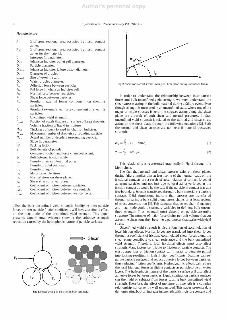
In order to understand the relationship between inter-particleforces and bulk unconfined yield strength, we must understand theshear stresses acting in the bulk material during a failure event. Eventhough strength is measured in an unconfined state, where one of themajor principle stresses is zero, the stresses acting along the shearplane are a result of both shear and normal pressures. In fact,unconfined yield strength is related to the normal and shear stressacting on the shear plane through the following equations [2]. Boththe normal and shear stresses are non-zero if material possessesstrength.
σn =fc2
· 1− sin /ð Þð Þ ð1Þ
τn =fc2
· cos /ð Þ ð2Þ
This relationship is represented graphically in Fig. 2 through theMohr circle.
The fact that normal and shear stresses exist on shear planesduring failure implies that at least some of the normal loads on thefrictional contacts are a result of accumulation of contact forces ofadjacent particles and not just due to local adhesive forces at thefriction contact as would be the case if the particle in contact was at afree boundary. Stress is transferred through a bulkmaterial via particlecontacts. DEM simulations indicate that stresses are transferredthrough shearing a bulk solid along stress chains or at least regionsof stress concentration [3]. This suggests that stress chain frequencyand magnitude could be primary variables in defining bulk uncon-fined strength. Thus, strength must depend on particle assemblystructure. The number of major force chains per unit volume that cutacross the shear zone then becomes a parameter that scales with yieldstress.
Unconfined yield strength is also a function of accumulation oflocal friction effects. Normal forces are translated into shear forcesthrough a coefficient of friction. Accumulated shear forces along theshear plane contribute to shear resistance and the bulk unconfinedyield strength. Therefore, local frictional effects must also affectstrength. Many factors contribute to friction at particle contacts. Theelastic asperities at friction contact can interact to generate partialinterlocking resulting in high friction coefficients. Coatings can se-parate particle surfaces and reduce adhesive forces between particles,thus reducing friction coefficients. Hydrodynamic effects can reducethe local frictional forces at sliding contacts as particle slide on waterlayers. The hydrophobic nature of the particle surface will also affectadhesive forces between particles. Liquid coatings on particle surfacescan then add or subtract from forces causing bulk unconfined yieldstrength. Therefore, the effect of moisture on strength is a complexrelationship not currently well understood. This paper presents datademonstrating both an increase in strengthwithmoisture content andFig. 1. Forces acting on particles in bulk assembly.
Fig. 2. Shear and normal stresses acting on shear plane during unconfined failure.
Nomenclature
Af % of cross sectional area occupied by major contactzones.
Afo % of cross sectional area occupied by major contactzones for dry material.
b Intercept fit parameter.Dout Johanson Indicizer outlet cell diameter.Dp Particle diameter.Dpiston Johanson Indicizer failure piston diameter.Dw Diameter of droplet.dvoxel Size of voxel in scan.Dw Water droplet diameter.Fad Adhesion force between particles.Ffail Fail force in Johanson Indicizer cell.FN Normal force between particles.FS Shear force between particles.Fσ Resultant external forces component on shearing
particles.Fτ Resultant external shear force component on shearing
particles.fc Unconfined yield strength.fvoxel Fraction of voxels that are on surface of large droplets.fw Volume fraction of liquid in mixture.Hfail Thickness of puck formed in Johanson Indicizer.Nmax Maximum number of droplets surrounding particle.Nact Actual number of droplets surrounding particle.m Slope fit parameter.PF Packing factor.γ Bulk density of powder.η Combined friction and force chain coefficient.ϕ Bulk Internal friction angle.ρa Density of air in interstitial pores.ρs Density of solid particles.ρw Density of liquid.σ1 Major principle stress.σn Normal stress on shear plane.τn Shear stress on shear plane.μp Coefficient of friction between particles.μdry Coefficient of friction between dry contacts.μwet Coefficient of friction between wet contacts.
2 K. Johanson et al. / Powder Technology 194 (2009) 1–9
Author's personal copy
a reduction in strength with moisture content and proposes somemechanisms to explain these observations.
2. Experimental
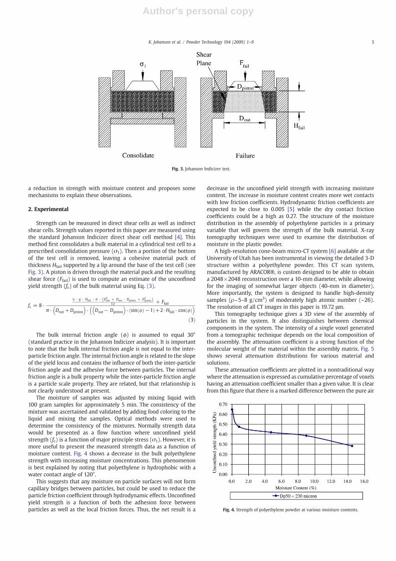
Strength can be measured in direct shear cells as well as indirectshear cells. Strength values reported in this paper are measured usingthe standard Johanson Indicizer direct shear cell method [4]. Thismethod first consolidates a bulk material in a cylindrical test cell to aprescribed consolidation pressure (σ1). Then a portion of the bottomof the test cell is removed, leaving a cohesive material puck ofthickness Hfail supported by a lip around the base of the test cell (seeFig. 3). A piston is driven through the material puck and the resultingshear force (Ffail) is used to compute an estimate of the unconfinedyield strength (fc) of the bulk material using Eq. (3).
fc = 8 ·γ · g · Hfail · π · D2
out + Dout · Dpiston + D2pistonð Þ
12 + Ffail
π · Dout +Dpiston
� �· Dout− Dpiston
� �· sin /ð Þ−1ð Þ+2·Hfail · cos /ð Þ
� �
ð3Þ
The bulk internal friction angle (ϕ) is assumed to equal 30°(standard practice in the Johanson Indicizer analysis). It is importantto note that the bulk internal friction angle is not equal to the inter-particle friction angle. The internal friction angle is related to the slopeof the yield locus and contains the influence of both the inter-particlefriction angle and the adhesive force between particles. The internalfriction angle is a bulk property while the inter-particle friction angleis a particle scale property. They are related, but that relationship isnot clearly understood at present.
The moisture of samples was adjusted by mixing liquid with100 gram samples for approximately 5 min. The consistency of themixture was ascertained and validated by adding food coloring to theliquid and mixing the samples. Optical methods were used todetermine the consistency of the mixtures. Normally strength datawould be presented as a flow function where unconfined yieldstrength (fc) is a function of major principle stress (σ1). However, it ismore useful to present the measured strength data as a function ofmoisture content. Fig. 4 shows a decrease in the bulk polyethylenestrength with increasing moisture concentrations. This phenomenonis best explained by noting that polyethylene is hydrophobic with awater contact angle of 120°.
This suggests that any moisture on particle surfaces will not formcapillary bridges between particles, but could be used to reduce theparticle friction coefficient through hydrodynamic effects. Unconfinedyield strength is a function of both the adhesion force betweenparticles as well as the local friction forces. Thus, the net result is a
decrease in the unconfined yield strength with increasing moisturecontent. The increase in moisture content creates more wet contactswith low friction coefficients. Hydrodynamic friction coefficients areexpected to be close to 0.005 [5] while the dry contact frictioncoefficients could be a high as 0.27. The structure of the moisturedistribution in the assembly of polyethylene particles is a primaryvariable that will govern the strength of the bulk material. X-raytomography techniques were used to examine the distribution ofmoisture in the plastic powder.
A high-resolution cone-beam micro-CT system [6] available at theUniversity of Utah has been instrumental in viewing the detailed 3-Dstructure within a polyethylene powder. This CT scan system,manufactured by ARACOR®, is custom designed to be able to obtaina 2048×2048 reconstruction over a 10-mm diameter, while allowingfor the imaging of somewhat larger objects (40-mm in diameter).More importantly, the system is designed to handle high-densitysamples (ρ~5–8 g/cm3) of moderately high atomic number (~26).The resolution of all CT images in this paper is 19.72 μm.
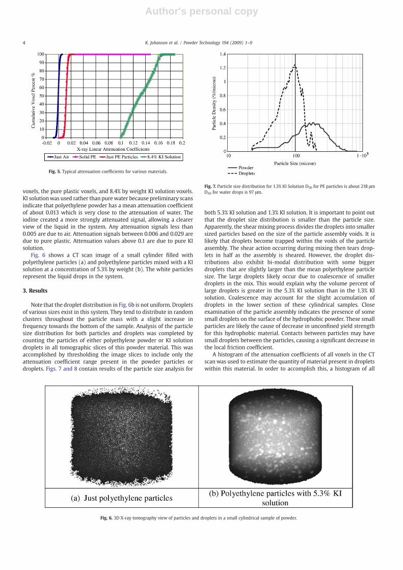
This tomography technique gives a 3D view of the assembly ofparticles in the system. It also distinguishes between chemicalcomponents in the system. The intensity of a single voxel generatedfrom a tomographic technique depends on the local composition ofthe assembly. The attenuation coefficient is a strong function of themolecular weight of the material within the assembly matrix. Fig. 5shows several attenuation distributions for various material andsolutions.
These attenuation coefficients are plotted in a nontraditional waywhere the attenuation is expressed as cumulative percentage of voxelshaving an attenuation coefficient smaller than a given value. It is clearfrom this figure that there is a marked difference between the pure air
Fig. 3. Johanson Indicizer test.
Fig. 4. Strength of polyethylene powder at various moisture contents.
3K. Johanson et al. / Powder Technology 194 (2009) 1–9
Author's personal copy
voxels, the pure plastic voxels, and 8.4% by weight KI solution voxels.KI solutionwas used rather than purewater because preliminary scansindicate that polyethylene powder has a mean attenuation coefficientof about 0.013 which is very close to the attenuation of water. Theiodine created a more strongly attenuated signal, allowing a clearerview of the liquid in the system. Any attenuation signals less than0.005 are due to air. Attenuation signals between 0.006 and 0.029 aredue to pure plastic. Attenuation values above 0.1 are due to pure KIsolution.
Fig. 6 shows a CT scan image of a small cylinder filled withpolyethylene particles (a) and polyethylene particles mixed with a KIsolution at a concentration of 5.3% by weight (b). The white particlesrepresent the liquid drops in the system.
3. Results
Note that the droplet distribution in Fig. 6b is not uniform. Dropletsof various sizes exist in this system. They tend to distribute in randomclusters throughout the particle mass with a slight increase infrequency towards the bottom of the sample. Analysis of the particlesize distribution for both particles and droplets was completed bycounting the particles of either polyethylene powder or KI solutiondroplets in all tomographic slices of this powder material. This wasaccomplished by thresholding the image slices to include only theattenuation coefficient range present in the powder particles ordroplets. Figs. 7 and 8 contain results of the particle size analysis for
both 5.3% KI solution and 1.3% KI solution. It is important to point outthat the droplet size distribution is smaller than the particle size.Apparently, the shear mixing process divides the droplets into smallersized particles based on the size of the particle assembly voids. It islikely that droplets become trapped within the voids of the particleassembly. The shear action occurring during mixing then tears drop-lets in half as the assembly is sheared. However, the droplet dis-tributions also exhibit bi-modal distribution with some biggerdroplets that are slightly larger than the mean polyethylene particlesize. The large droplets likely occur due to coalescence of smallerdroplets in the mix. This would explain why the volume percent oflarge droplets is greater in the 5.3% KI solution than in the 1.3% KIsolution. Coalescence may account for the slight accumulation ofdroplets in the lower section of these cylindrical samples. Closeexamination of the particle assembly indicates the presence of somesmall droplets on the surface of the hydrophobic powder. These smallparticles are likely the cause of decrease in unconfined yield strengthfor this hydrophobic material. Contacts between particles may havesmall droplets between the particles, causing a significant decrease inthe local friction coefficient.
A histogram of the attenuation coefficients of all voxels in the CTscan was used to estimate the quantity of material present in dropletswithin this material. In order to accomplish this, a histogram of all
Fig. 5. Typical attenuation coefficients for various materials.
Fig. 6. 3D X-ray tomography view of particles and droplets in a small cylindrical sample of powder.
Fig. 7. Particle size distribution for 1.3% KI Solution D50 for PE particles is about 218 μmD50 for water drops is 97 μm.
4 K. Johanson et al. / Powder Technology 194 (2009) 1–9
Author's personal copy
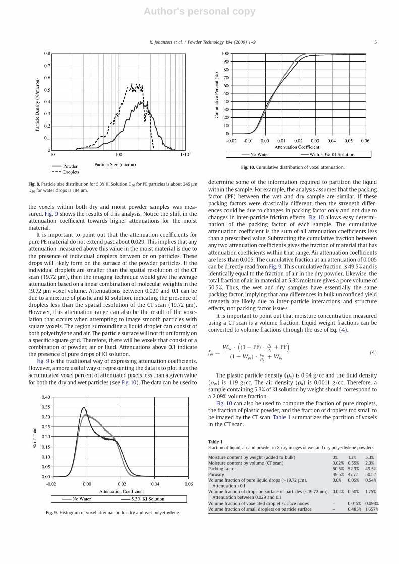
the voxels within both dry and moist powder samples was mea-sured. Fig. 9 shows the results of this analysis. Notice the shift in theattenuation coefficient towards higher attenuations for the moistmaterial.
It is important to point out that the attenuation coefficients forpure PE material do not extend past about 0.029. This implies that anyattenuation measured above this value in the moist material is due tothe presence of individual droplets between or on particles. Thesedrops will likely form on the surface of the powder particles. If theindividual droplets are smaller than the spatial resolution of the CTscan (19.72 μm), then the imaging technique would give the averageattenuation based on a linear combination of molecular weights in the19.72 μm voxel volume. Attenuations between 0.029 and 0.1 can bedue to a mixture of plastic and KI solution, indicating the presence ofdroplets less than the spatial resolution of the CT scan (19.72 μm).However, this attenuation range can also be the result of the voxe-lation that occurs when attempting to image smooth particles withsquare voxels. The region surrounding a liquid droplet can consist ofboth polyethylene and air. The particle surfacewill not fit uniformly ona specific square grid. Therefore, there will be voxels that consist of acombination of powder, air or fluid. Attenuations above 0.1 indicatethe presence of pure drops of KI solution.
Fig. 9 is the traditional way of expressing attenuation coefficients.However, a more useful way of representing the data is to plot it as theaccumulated voxel percent of attenuated pixels less than a given valuefor both the dry and wet particles (see Fig. 10). The data can be used to
determine some of the information required to partition the liquidwithin the sample. For example, the analysis assumes that the packingfactor (PF) between the wet and dry sample are similar. If thesepacking factors were drastically different, then the strength differ-ences could be due to changes in packing factor only and not due tochanges in inter-particle friction effects. Fig. 10 allows easy determi-nation of the packing factor of each sample. The cumulativeattenuation coefficient is the sum of all attenuation coefficients lessthan a prescribed value. Subtracting the cumulative fraction betweenany two attenuation coefficients gives the fraction of material that hasattenuation coefficients within that range. Air attenuation coefficientsare less than 0.005. The cumulative fraction at an attenuation of 0.005can be directly read from Fig. 9. This cumulative fraction is 49.5% and isidentically equal to the fraction of air in the dry powder. Likewise, thetotal fraction of air in material at 5.3% moisture gives a pore volume of50.5%. Thus, the wet and dry samples have essentially the samepacking factor, implying that any differences in bulk unconfined yieldstrength are likely due to inter-particle interactions and structureeffects, not packing factor issues.
It is important to point out that moisture concentration measuredusing a CT scan is a volume fraction. Liquid weight fractions can beconverted to volume fractions through the use of Eq. (4).
fw =Ww · 1− PFð Þ · ρa
ρs+ PF
� �1− Wwð Þ · ρw
ρs+ Ww
ð4Þ
The plastic particle density (ρs) is 0.94 g/cc and the fluid density(ρw) is 1.19 g/cc. The air density (ρa) is 0.0011 g/cc. Therefore, asample containing 5.3% of KI solution by weight should correspond toa 2.09% volume fraction.
Fig. 10 can also be used to compute the fraction of pure droplets,the fraction of plastic powder, and the fraction of droplets too small tobe imaged by the CT scan. Table 1 summarizes the partition of voxelsin the CT scan.
Fig. 8. Particle size distribution for 5.3% KI Solution D50 for PE particles is about 245 μmD50 for water drops is 184 μm.
Fig. 9. Histogram of voxel attenuation for dry and wet polyethylene.
Table 1Fraction of liquid, air and powder in X-ray images of wet and dry polyethylene powders.
Moisture content by weight (added to bulk) 0% 1.3% 5.3%Moisture content by volume (CT scan) 0.02% 0.55% 2.3%Packing factor 50.5% 52.3% 49.5%Porosity 49.5% 47.7% 50.5%Volume fraction of pure liquid drops (N19.72 μm).
Attenuation N0.10.0% 0.05% 0.54%
Volume fraction of drops on surface of particles (b19.72 μm).Attenuation between 0.029 and 0.1
0.02% 0.50% 1.75%
Volume fraction of voxelated droplet surface nodes – 0.015% 0.093%Volume fraction of small droplets on particle surface – 0.485% 1.657%
Fig. 10. Cumulative distribution of voxel attenuation.
5K. Johanson et al. / Powder Technology 194 (2009) 1–9
Author's personal copy
Table 1 shows the basic breakdown of where the moisture is in thesystem. However, the fraction of drops on the particle surfaces alsocontains some voxels that contain surface nodes on the larger droplets.If we assume that these larger droplets are nearly spherical, then wecan compute the fraction of the voxels in the 0.029 to 0.1 attenuationrange that resulted from voxelated droplets. The fraction (fvoxel) ofthe liquid droplet that is attached to avoxelated surface depends on thesize of the droplets (Dp) relative to the voxel resolution (dvoxel). If theparticles can be reasonably represented by spherical particles, thenthe quantity of voxelated material on the surface can be approximatedby computing the volume occupied by a spherical shell that is half avoxel thick on average. Using this assumption, Eq. (5) shows the frac-tion of volume in voxelated surface voxels.
fvoxel = 3 ·
dvoxel2
� �Dp
− 3 ·
dvoxel2
� �Dp
0@
1A2
+dvoxel2
� �Dp
0@
1A3
ð5Þ
There is a range of droplet particle sizes producing a range of voxelfractions. However, the particle size distributions in Figs. 7 and 8 canbe used along with Eq. (5) to estimate the average voxel fraction ofsurface voxels that have attenuation in the 0.029 to 0.10 range. 17.3% ofthe pure droplet voxels for the 5.3% moisture material end up in themid-range attenuation. Likewise, 30.0% of the pure droplet voxels forthe 1.3% moisture material end up in this mid-range attenuation. Theremaining moisture in this mid-range attenuation is on the surface ofthe particles and can change the inter-particle coefficient of frictiondue to lubrication effects. Table 1 suggests that 1.657% of the totalvolume for the 5.3% moisture material is due to moisture on thesurface of particles. Since the resolution of the CT scan is 19.72 μm, themaximum size of non-imaged droplets on particle surfaces is also19.72 μm. Droplets larger than this would appear as individual dropswhen constructing the tomographic image. However, it seemsunreasonable to assume that droplets on all particle surfaces have aconstant diameter of 19.72 μm. Instead, a more reasonable assumption
would be that droplet size scales with the size of the particle. Thelargest particles would have droplets nearly 19.72 μm in diameter,while the smaller particles would contain proportionally smallerdroplets. It can be shown that a constant size droplet formed on thesurface of a spherical particle could be distributed in N distinctparticles and cover the surface where the droplets were just touching.This maximum coverage is given by Eq. (6) where Dp is the particlediameter. Dw is the droplet diameter, and Nmax is the maximumnumber of possible contacts.
Nmax =2:05 · π
4 · 1 + DwDp
� �
1 + DwDp
� �−
ffiffiffiffiffiffiffiffiffiffiffiffiffiffiffiffiffiffiffiffiffiffiffiffiffiffiffiffiffiffiffi2 · Dw
Dp+ 1
� �r ð6Þ
For example, if the droplet size is the same as the particle diameter,then the above equation suggests that, at most, 12 droplets couldsurround the surface of the particle. However, the largest particle inthe powder is about 600 μm, while the droplet on this surface wouldbe about 19.72 μm. Eq. (4) suggests that the number of possibledroplets on this large particle would be about 3180. It is important topoint out that, if the size ratio of droplet size to particle size isconstant, then the number of possible droplets per particle would beindependent of the particle size. If the actual number of droplets onthe particle surface were known, then the percent of area covered bydroplets on the surface could be determined. The actual number ofdroplets on a particle surface could be obtained using Eq. (7):
Nact =fw
1− fw·
Dp
Dw
� �3ð7Þ
where fw is the fraction of moisture on the surface of the particles. Inthe example above, the moisture content on the particle surfaces isabout 1.657% based on total volume for the 5.3% moisture material.This corresponds to an actual number of droplets on the surface ofabout 474. Since the maximum number of droplets on the surface is3180, the surface area covered by liquid drops is about 15%. Theprobability of an inter-particle contact having a liquid droplet betweenadjacent particles is roughly proportional to the percent coverage bydrops. Thus, one can assume that the contact is either wet or dry anduse a linear combination of wet and dry friction coefficients toestimate the average friction coefficient for the bulk (μp). In this paper,we assume that the dry friction coefficient (μdry) is 0.27 and the wetcontact friction coefficient (μwet) is 0.005. The overall frictioncoefficient is computed from Eq. (8) and results in μp=0.230 for thecase of a 5.3% mixture of KI solution.
μp =Nact
Nmax· μwet + 1− Nact
Nmax
� �· μdry ð8Þ
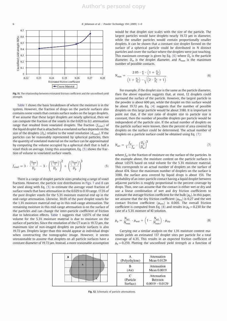
Carrying out a similar analysis on the 1.3% moisture content ma-terials yields an estimated 137 droplet sites per particle for a totalcoverage of 4.3%. This results in an expected friction coefficient ofμp=0.259. Plotting the unconfined yield strength as a function of
Fig.11. The relationship between estimated friction coefficient and the unconfined yieldstrength.
Fig. 12. Schematic of particle attenuations.
6 K. Johanson et al. / Powder Technology 194 (2009) 1–9
Author's personal copy
estimated average friction coefficient yields the results shown inFig. 11.
Increasing the coefficient of friction between particles increasesthe unconfined yield strength. However, the behavior does not seemto follow a linear relationship. This nonlinearity can be explained byincluding some of the structure effects. Discreet element simulationsindicate that shearing assemblies of particulate matter form forcechains. The loads appear to distribute though this bulk material alongpredominate force chains. One could assume that the unconfined yieldstrength is a function of how many major force chains are shearedduring flow. If this were the case, the relative fraction of area occupiedby these force chains should vary in proportion to the unconfinedyield strength. The CT scans of these particles gives a means of esti-mating these predominant force chains. The slices obtained from thescans can be thresholded to obtain the voxels at the edge of theparticles (Fig. 12).
Consider a schematic of a particle given in Fig. 12. A voxel located atpoint B would have attenuation close to 0.0019 (or that of air). A voxellocated at point A would have attenuation near 0.129. A voxel locatedat point C would be somewhere in between.
An attenuation threshold range of 0.0062 to 0.012 was chosen toselect just the edge of particles. The next step was to select only thecontiguous regions where the size of the adjoining voxels in the x–yplane was in excess of 525 μm (at least 2.5 particles based on D50). Ifforce chains form in the material, they will form along predominate
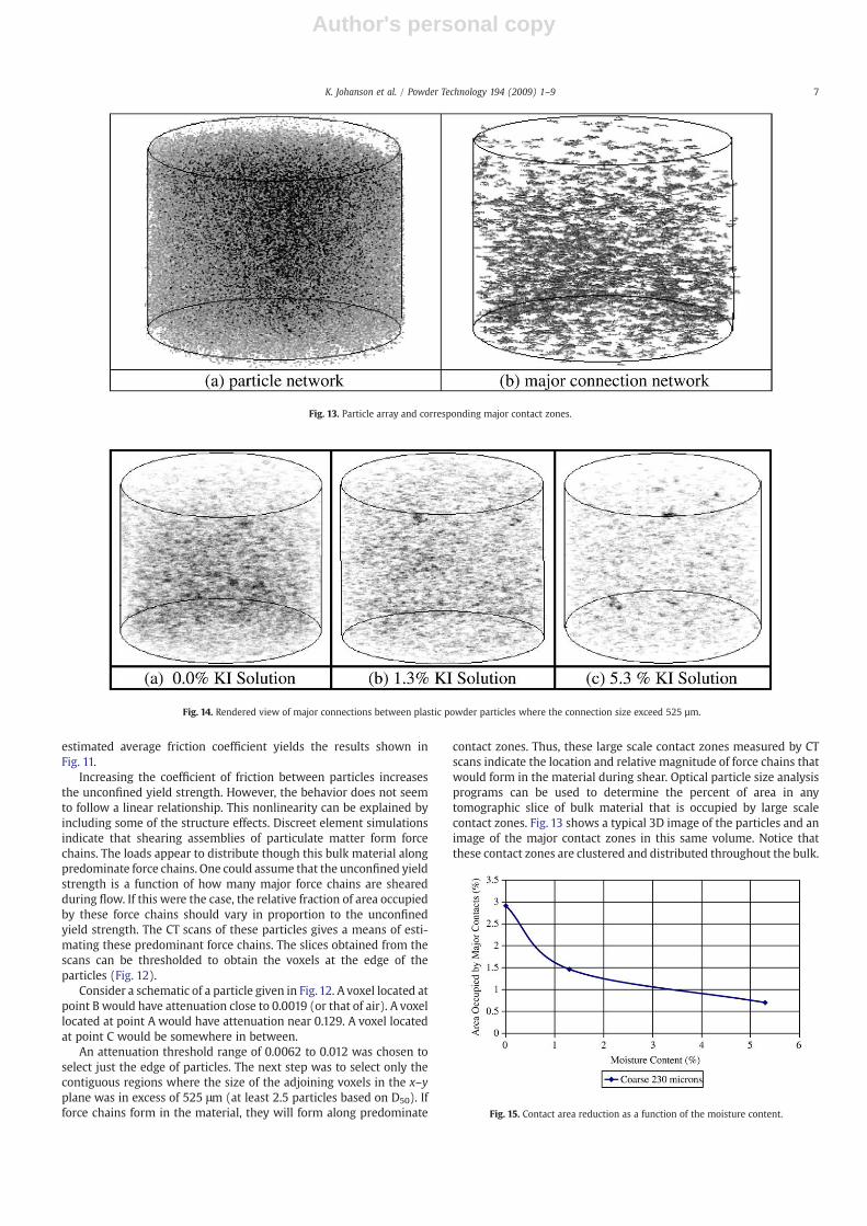
contact zones. Thus, these large scale contact zones measured by CTscans indicate the location and relative magnitude of force chains thatwould form in the material during shear. Optical particle size analysisprograms can be used to determine the percent of area in anytomographic slice of bulk material that is occupied by large scalecontact zones. Fig. 13 shows a typical 3D image of the particles and animage of the major contact zones in this same volume. Notice thatthese contact zones are clustered and distributed throughout the bulk.
Fig. 14. Rendered view of major connections between plastic powder particles where the connection size exceed 525 µm.
Fig. 13. Particle array and corresponding major contact zones.
Fig. 15. Contact area reduction as a function of the moisture content.
7K. Johanson et al. / Powder Technology 194 (2009) 1–9
Author's personal copy
This procedure was done to the CT scans at various moisturecontents and displayed graphically in Fig. 14. This clearly indicates areduction in major contact area with an increase in moisture content.
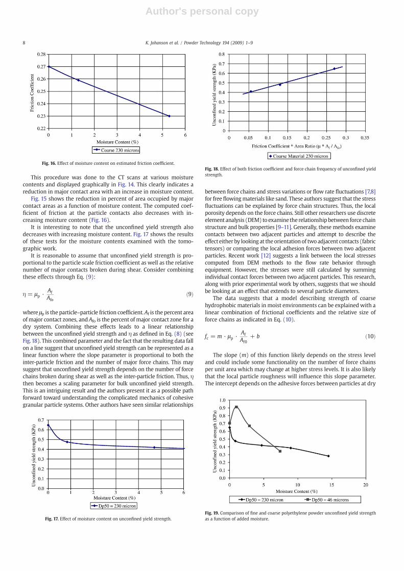
Fig. 15 shows the reduction in percent of area occupied by majorcontact areas as a function of moisture content. The computed coef-ficient of friction at the particle contacts also decreases with in-creasing moisture content (Fig. 16).
It is interesting to note that the unconfined yield strength alsodecreases with increasing moisture content. Fig. 17 shows the resultsof these tests for the moisture contents examined with the tomo-graphic work.
It is reasonable to assume that unconfined yield strength is pro-portional to the particle scale friction coefficient as well as the relativenumber of major contacts broken during shear. Consider combiningthese effects through Eq. (9):
η = μp ·Af
Afoð9Þ
where μp is the particle–particle friction coefficient.Af is the percent areaof major contact zones, and Afo is the percent of major contact zone for adry system. Combining these effects leads to a linear relationshipbetween the unconfined yield strength and η as defined in Eq. (8) (seeFig.18). This combined parameter and the fact that the resulting data fallon a line suggest that unconfined yield strength can be represented as alinear function where the slope parameter is proportional to both theinter-particle friction and the number of major force chains. This maysuggest that unconfined yield strength depends on the number of forcechains broken during shear as well as the inter-particle friction. Thus, ηthen becomes a scaling parameter for bulk unconfined yield strength.This is an intriguing result and the authors present it as a possible pathforward toward understanding the complicated mechanics of cohesivegranular particle systems. Other authors have seen similar relationships
between force chains and stress variations or flow rate fluctuations [7,8]for free flowingmaterials like sand. These authors suggest that the stressfluctuations can be explained by force chain structures. Thus, the localporosity depends on the force chains. Still other researchers use discreteelement analysis (DEM) to examine the relationshipbetween force chainstructure and bulk properties [9–11]. Generally, these methods examinecontacts between two adjacent particles and attempt to describe theeffect either by looking at theorientationof two adjacent contacts (fabrictensors) or comparing the local adhesion forces between two adjacentparticles. Recent work [12] suggests a link between the local stressescomputed from DEM methods to the flow rate behavior throughequipment. However, the stresses were still calculated by summingindividual contact forces between two adjacent particles. This research,along with prior experimental work by others, suggests that we shouldbe looking at an effect that extends to several particle diameters.
The data suggests that a model describing strength of coarsehydrophobic materials in moist environments can be explained with alinear combination of frictional coefficients and the relative size offorce chains as indicated in Eq. (10).
fc = m · μp ·Af
Af0+ b ð10Þ
The slope (m) of this function likely depends on the stress leveland could include some functionality on the number of force chainsper unit area which may change at higher stress levels. It is also likelythat the local particle roughness will influence this slope parameter.The intercept depends on the adhesive forces between particles at dry
Fig. 16. Effect of moisture content on estimated friction coefficient.
Fig. 17. Effect of moisture content on unconfined yield strength.
Fig. 18. Effect of both friction coefficient and force chain frequency of unconfined yieldstrength.
Fig. 19. Comparison of fine and coarse polyethylene powder unconfined yield strengthas a function of added moisture.
8 K. Johanson et al. / Powder Technology 194 (2009) 1–9
Author's personal copy
surface conditions. This coefficient is dependent on the strength of vander Waals forces between dry particles and should be expected toincrease with a decrease in particle size. The local roughness may alsoinfluence the intercept since inter-particle forces in dry conditions areshort range and the roughness provides additional particle separation.The dependence of these parameters on particle scale propertiesshould be a topic of further research.
Particle size has a distinct effect on the relationship betweenunconfined yield strength and moisture content. Unfortunately, thiseffect is very non-linear as indicated in Fig. 19.
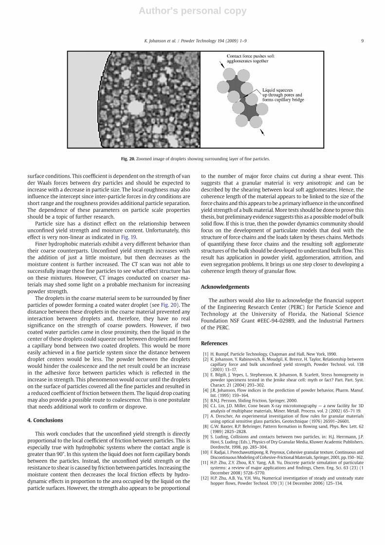
Finer hydrophobic materials exhibit a very different behavior thantheir coarse counterparts. Unconfined yield strength increases withthe addition of just a little moisture, but then decreases as themoisture content is further increased. The CT scan was not able tosuccessfully image these fine particles to see what effect structure hason these mixtures. However, CT images conducted on coarser ma-terials may shed some light on a probable mechanism for increasingpowder strength.
The droplets in the coarse material seem to be surrounded by finerparticles of powder forming a coated water droplet (see Fig. 20). Thedistance between these droplets in the coarse material prevented anyinteraction between droplets and, therefore, they have no realsignificance on the strength of coarse powders. However, if twocoated water particles came in close proximity, then the liquid in thecenter of these droplets could squeeze out between droplets and forma capillary bond between two coated droplets. This would be moreeasily achieved in a fine particle system since the distance betweendroplet centers would be less. The powder between the dropletswould hinder the coalescence and the net result could be an increasein the adhesive force between particles which is reflected in theincrease in strength. This phenomenonwould occur until the dropletson the surface of particles covered all the fine particles and resulted ina reduced coefficient of friction between them. The liquid drop coatingmay also provide a possible route to coalescence. This is one postulatethat needs additional work to confirm or disprove.
4. Conclusions
This work concludes that the unconfined yield strength is directlyproportional to the local coefficient of friction between particles. This isespecially true with hydrophobic systems where the contact angle isgreater than 90°. In this system the liquid does not form capillary bondsbetween the particles. Instead, the unconfined yield strength or theresistance to shear is causedby frictionbetweenparticles. Increasing themoisture content then decreases the local friction effects by hydro-dynamic effects in proportion to the area occupied by the liquid on theparticle surfaces. However, the strength also appears to be proportional
to the number of major force chains cut during a shear event. Thissuggests that a granular material is very anisotropic and can bedescribed by the shearing between local soft agglomerates. Hence, thecoherence length of the material appears to be linked to the size of theforce chainsand this appears to be aprimary influence in theunconfinedyield strength of a bulkmaterial. More tests should be done to prove thisthesis, but preliminaryevidence suggests this as apossiblemodel of bulksolid flow. If this is true, then the powder dynamics community shouldfocus on the development of particulate models that deal with thestructure of force chains and the loads taken by theses chains. Methodsof quantifying these force chains and the resulting soft agglomeratestructures of the bulk should bedeveloped to understand bulkflow. Thisresult has application in powder yield, agglomeration, attrition, andeven segregation problems. It brings us one step closer to developing acoherence length theory of granular flow.
Acknowledgements
The authors would also like to acknowledge the financial supportof the Engineering Research Center (PERC) for Particle Science andTechnology at the University of Florida, the National ScienceFoundation NSF Grant #EEC-94-02989, and the Industrial Partnersof the PERC.
References
[1] H. Rumpf, Particle Technology, Chapman and Hall, New York, 1990.[2] K. Johanson, Y. Rabinovich, B. Moudgil, K. Breece, H. Taylor, Relationship between
capillary force and bulk unconfined yield strength, Powder Technol. vol. 138(2003) 13–17.
[3] E. Bilgili, J. Yepes, L. Stephenson, K. Johanson, B. Scarlett, Stress homogeneity inpowder specimens tested in the Jenike shear cell: myth or fact? Part. Part. Syst.Charact. 21 (2004) 293–302.
[4] J.R. Johanson, Flow indices in the prediction of powder behavior, Pharm. Manuf.Int. (1995) 159–164.
[5] B.N.J. Persson, Sliding Friction, Springer, 2000.[6] C.L. Lin, J.D. Miller, Cone beam X-ray microtomography — a new facility for 3D
analysis of multiphase materials, Miner. Metall. Process. vol. 2 (2002) 65–71 19.[7] A. Drescher, An experimental investigation of flow rules for granular materials
using optical sensitive glass particles, Geotechnique (1976) 26591–26601.[8] G.W. Baxter, R.P. Behringer, Pattern formation in flowing sand, Phys. Rev. Lett. 62
(1989) 2825–2828.[9] S. Luding, Collisions and contacts between two particles, in: H.J. Herrmann, J.P.
Hovi, S. Luding (Eds.), Physics of Dry Granular Media, Kluwer Academic Publishers,Dordrecht, 1998, pp. 285–304.
[10] F. Radjai, I. Preechawuttipong, R. Peyroux, Cohesive granular texture, Continuous andDiscontinuousModelingof Cohesive-FrictionalMaterials, Springer, 2001, pp.150–162.
[11] H.P. Zhu, Z.Y. Zhou, R.Y. Yang, A.B. Yu, Discrete particle simulation of particulatesystems: a review of major applications and findings, Chem. Eng. Sci. 63 (23) (1December 2008) 5728–5770.
[12] H.P. Zhu, A.B. Yu, Y.H. Wu, Numerical investigation of steady and unsteady statehopper flows, Powder Technol. 170 (3) (14 December 2006) 125–134.
Fig. 20. Zoomed image of droplets showing surrounding layer of fine particles.
9K. Johanson et al. / Powder Technology 194 (2009) 1–9