the art of woodworking vol 05 - home workshop.pdf
TRANSCRIPT

{',*
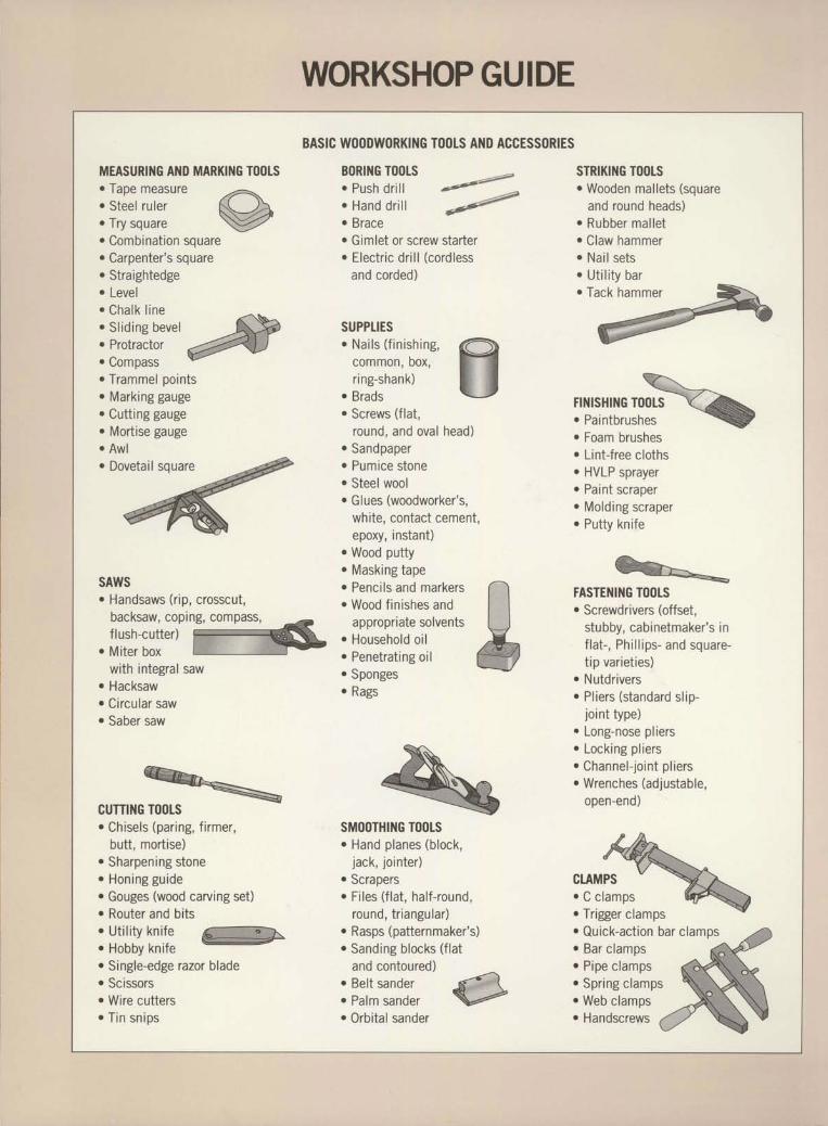
MEASURING AND MARKING TOOTS. Tape measure. Steel ruler. Try square. Combinat ion square. Carpenter's square. Straightedge. Level. Cha l k l i ne. Slidins bevel
ry:::'ff:::'a. Trammel pointso Marking gauge. Cutting gauge. Mortise gauge. Awl. Dovetail square
SAWS. Handsaws (rip, crosscut,
backsaw, coping, compass, _-flush-cutter) ref-
. Miter box ['i'.' ''r]'ttP
with integral saw. Hacksaw. Circular saw. Saber saw
CUTTING TOOLS. Chisels (par ing, f i rmer,
butt, mortise). Sharpening stoneo Hon ing gu ide. Gouges (wood carving set). Router and bits. U t i r i t y k n i f e
@. HODDY KNIIC
. Single-edge razor blade
. Scissors
. Wire cutters
. Tin snips
BASIC W()ODWORKING TO()TS AI{D ACCESSORIES
BORING TOOLS. Push d r i l l. Hand d r i l l. Brace. Gimlet or screw starter. Electr ic dr i l l (cordless
and corded)
SUPPTIESr Na i ls ( f in ish ing ,
common, box,r ing-shank)
. Brads
. Screws (flat,
round, and oval head)r Sandpaper. Pumice stone. Steel wool. Glues (woodworker's,
white, contact cement,epoxy, instant)
. Wood putty
. Masking tape
. Penci ls and markers
. Wood f in ishes andappropriate solvents
. Household o i lo Penetrating oil. Spongeso Reoq
SMOOTHING TOOTS. Hand planes (block,
jack, jo inter). Scrapers. Fi les ( f lat , hal f-round,
round, tr iangular). Rasps (patternmaker's). Sanding blocks ( f lat
and contoured)
:3: l l ' : : f f : ,#. Orbi tal sander
F'4"4
'sF
STRIKING TOOLS. Wooden mallets (square
and round heads). Rubber mal let. Claw hammerr Nai l sets. Ut i l i ty barr Tack hammer
v\\-YFlNlSHlNc t00LS
\1+
. Foam brushes
. Lint-free cloths
. HVLP sprayer
. Paint scraper
. Molding scraper
. Putty knife
FASTEI{ING TOOLS. Screwdrivers (offset,
stubby, cabinetmaker 's inf lat- , Phi l l ips- and square-t ip var iet ies)
o Nutdriversr Pl iers (standard sl ip-
joint type)r I n n o - n n q p n l i o r c
. Locking pl iers
. Channel- joint pl iers
. Wrenches (adj ustable,open-end)
:TT,fu-w
. Trigger clamps v
. Quick-act ion bar c lamos
. Bar clamps
. Pipe clamps
. Spring clampso Web clamps. Handscrews
WORKSHOPGUIDE
ItI
ttI
I
tI
I
I
I
I
I
I
I
I
tI
I
I
tI
I
I
I
I
tItI
I
t3rII

IItIItI
THE ART OF WOODWORKING
HOMEWORI$HOP

THE ART OF WOODVV'ORKING
HOMEWORI$HOP
TIME-LIFE BOOKSALEXANDRIA, VIRGINIA
ST. REMY PRESSMONTREAL. NEW YORK

PUBLISHERPRESIDENT
Series EditorSeries Art Director
Senior Editors
Art Directors
DesignersResearch Editor
Picture EditorWriters
C o n t r ib ut i ng IIlu st r ht o r s
AdministratorProduction ManagerSystem Coordinator
Photographer
Kenneth WinchesterPierre Ldveill6
Pierre Home-DouglasFrancine LemieuxMarc Cassini (Text)Heather Mills (Research)Normand Boudreault, Luc Germain,Solange LabergeJean-Guy Doiron, Michel GigudreIim McRaeChristopher JacksonAndrew Jones, Rob LutesGilles Beauchemin, Rolland Bergera,Jean-Pierre Bourgeois, Michel Blais,Nicole Chartier, Ronald Durepos,Philippe Gauvreau, G€rard Mariscalchi,Jacques Perrault, Robert Paquet,Iames ThdrienNatalie WatanabeMichelle TurbideIean-Luc RovRobert Chariier
THECONSULTANTS
Jon Arno is a consultant, cabinetmaker andfreelance writer who lives in Tioy, Michigan.He also conducts seminars on wood identifica-tion and early American furniture design.
Giles Miller-Mead taught advanced cabinet-rnaking at Montreal technical schools for morethan ten years. A native ofNew Zealand, he hasworked as a restorer of antique furniture.
foseph Truini is Senior Editor of HoneMechanixmagazine. A former Shop and ToolsEditor of Popular Mechanics, he has worked asa cabinetmaker, home improvement contractorand carpenter.
Home Workshopp. cm.-(The Art of Woodworking)
Includes index.ISBN 0-8094-9920-7 . (trade\ISBN 0-8094-992 1-s oib)1. Woodshops.2. Woodwork--Equipment and supplies.I. Time-Life Books. II. SeriesTTI52.H6 1993684' .08-dc20 92-682r
CIP
For information about any Time-Life book,please call l-800-621-7026, or write:Reader InformationTime-Life Customer ServiceP.O. Box C-32068Richmond, Virginia2326t-2068
@ 1993 Time-Life Books Inc.All rights reserved.No part of this book may be reproduced inany form or by any electronic or mechanicalmeans, including information storage andretrieval devices or systems, without priorwritten permission from the publisher, exceptthat briefpassages may be quoted for reviews.First printing. Printed in U.S.A.Published simultaneously in Canada.
TIME-LIFE is a trademark of Time WarnerInc. U.S.A.
THE ART OF WOODWORKING was produced byST. REMY PRESS
Time-Life Books is a division of Time-Life Inc.,a wholly owned subsidiary of
THE TIME INC. BOOK COMPANY
TIME-LIFEBOOKS
PresidentVice-President
Editor-in-ChiefDirector of Editorial Resources
Marketing DirectorEditorial DirectorConsulting Editor
Production Manager
lohn D. HallNancy K. JonesThomas H. FlahertyElise D. futter-Clough
Regina HallLee HassigJohn R. SullivanMarlene Zack

CONTENTS
6 INTRODUCTION
12 SAFETYL4 Accident prevention15 Working with safe finishes16 Fire safety17 Electrical safety18 Personal safety gear23 First aid
28 SHOP TAYOUT30 Workshop planning32 Planning for stationary tools36 Shop organization4L Electrical power43 Lishtins44 FlSors, i"a[s, and ceilings45 Heating and ventilation
46 WORKBENCH48 Anatomv of a workbench50 Building the base53 Building the top56 Vises and accessories62 Bench dogs and hold downs
68 SHOP ACCESSORIES70 A store of shop accessories72 Air compressors74 Portable generators76 Bench grinders78 Dust collection85 Portable dust collection
88 STORAGE90 Storing wood94 Storing tools and supplies
IIO WORKSURFACESLL2 Work tables118 SawhorsesI25 Work supportsI29 Extension tablesI34 Tool stands and tables
I4O GLOSSARY
I42 INDEX
I44 ACKNOWTEDGMENTS
INTRODUCTION
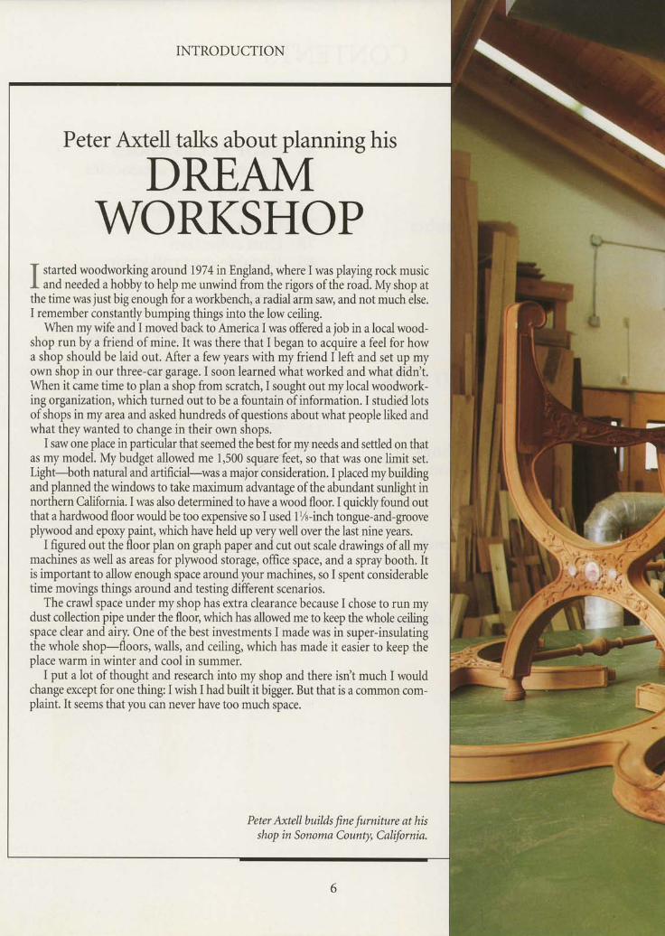
Peter Axtell talks about planning his
DREAIVIWORKSHOP
f started woodworking around 1974 nEngland, where I was playing rock musicI and needed a hobby to help me unwind from the rigors of the road. My shop atthe time was just big enough for a workbench, a radial arm saw and not much else.I remember constantlybumping things into the low ceiling.
When mywife and I moved back to America I was offered a job in a local wood-shop run by a friend of mine. It was there that I began to acquire a feel for howa shop should be laid out. After a few years with my friend I left and set up myown shop in our three-car garuge.I soon learned what worked and what didn'gWhen it came time to plan a shop from scratch,I sought out mylocalwoodwqrft-ing organization, which turned out to be a fountain of information. I studi/d lotsof shops in my area and asked hundreds of questions about what people liked andwhat they wanted to change in their own shops.
I saw one place in particular that seemed the best forjry needs and settled on thatas my model. My budget allowed me 1,500 sqlrgtt.feet, so that was one limit set.Light-both natural and artificial-was a maior consideration. I placed mybuildingand plannedthe windows to take maximum advantage ofthe abundant sunlight innorthern California. I was also determined to have a wood floor. I quickly found outthat a hardwood floor would be too expensive so I used l%-inch tongue-and-grooveplywood and epory paint, which have held up very well over the last nine years.
I figured out the floor plan on graph paper and cut out scale drawings of all mymachines as well as areas for plywood storage, office space, and a spray booth. Itis important to allow enough space around your machines, so I spent considerabletime movings things around and testing different scenarios.
The crawl space under myshop has extra clearance because I chose to run mydust collection pipe under the floor, which has allowed me to keep the whole ceilingspace clear and airy. One of the best investments I made was in super-insulatingthe whole shop-floors, walls, and ceiling, which has made it easier to keep theplace warm in winter and cool in summer.
I put a lot of thought and research into my shop and there isrt't much I wouldchange except for one thing: I wish I had built it bigger. But that is a common com-plaint. It seems that you can never have too much space.
Peter Axtell builik fine furniture at hisshop in SonomaCounty, Californin.


bUa -- - ---'-lFr o cnotrsrrxT'cAf€ cttEz'tAllpsE
- - { - F
INTRODUCTION
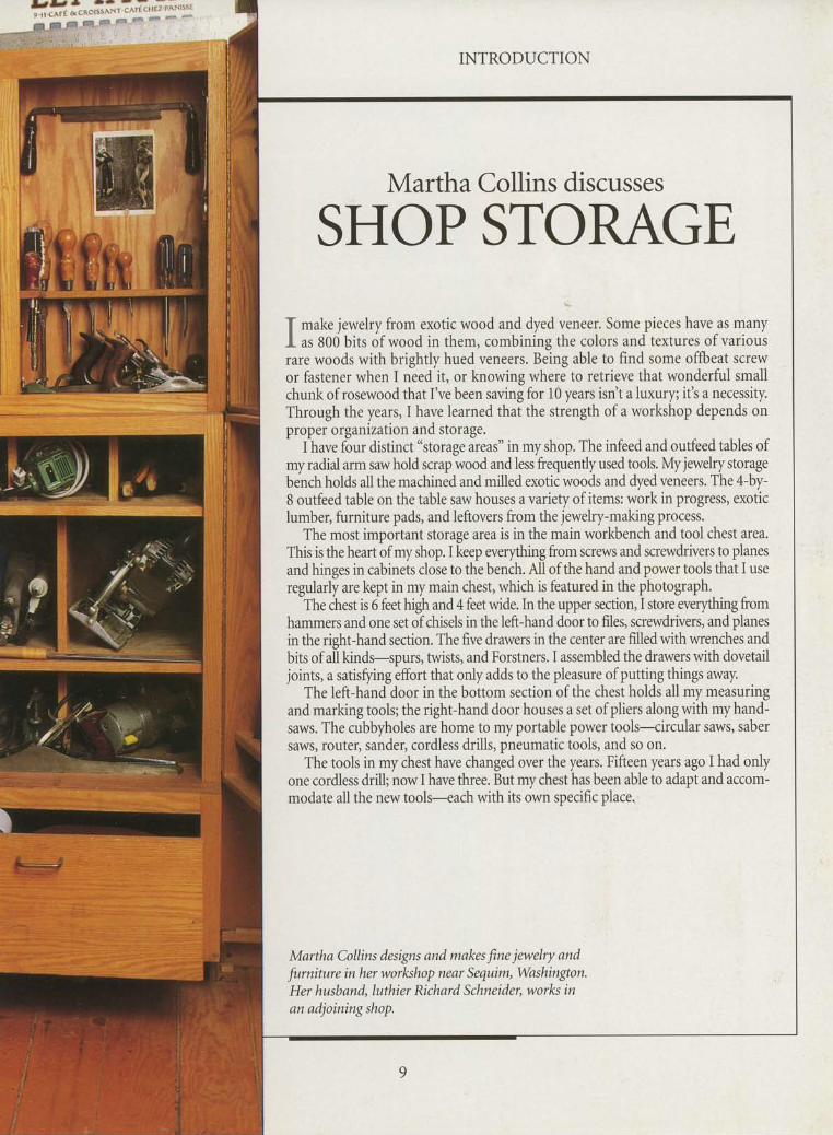
Martha Collins discusses
SHOP STORAGE
I make jewelry from exotic wood and dy.d ulne.r. Some pieces have as manyI as 800 bits of wood in them, combining the colors and textures of variousrare woods with brightly hued veneers. Being able to find some offbeat screwor fastener when I need it, or knowing where to retrieve that wonderful smallchunk of rosewood that I've been saving for 10 years isrlt a luxury; it's a necessity.Through the years, I have learned that the strengh of a workshop depends onproPer organization and storage.
I have four distinct "storage areas" in my shop. The infeed and outfeed tables ofmy radial arm saw hold scrap wood and less frequently used tools My jewelry storagebench holds all the machined and milled exotic woods and dyed veneers. The 4-by-8 outfeed table on the table saw houses a variety of items: work in progress, exoticlumber, furniture pads, and leftovers from the jewelry-making process.
The most important storage area is in the main workbench and tool chest area.This is the heart of my shop. I keep werything from screws and screwdrivers to planesand hinges in cabinets close to the bench. All of the hand and power tools that I useregularly are kept in my main chest, which is featured in the photograph.
The chest is 6 feet high and 4 feet wide. In the upper section, I store werything fromhammers and one set of chisels in the left-hand door to files, screwdrivers, and planesin the right-hand section. The five drawers in the center are filled with wrenches andbits of all kindrspurs, twists, and Forstners. I assembled the drawers with dovetailjoints, a satisfring effort that only adds to the pleasure of putting things away.
The left-hand door in the bottom section of the chest holds all my measuringand marking tools; the right-hand door houses a set of pliers along with my hand-saws. The cubbyholes are home to my portable power tools-circular saws, sabersaws, router, sander, cordless drills, pneumatic tools, and so on.
The tools in my chest have changed over the years. Fifteen years ago I had onlyone cordles d,rill; now I have three. But my chest has been able to adapt and accom-modate all the new tools-each with its own specific place.
Martha Collins designs and makes fine jewelry and
furninne in her worhshop near Sequim, Washington.Her husband, luthier Richard Schneider, worlcs inan adjoiningshop.

INTRODUCTION
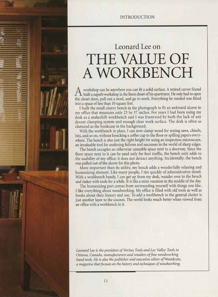
Leonard Lee on
THE\ALUE OFAWORKBENCHworlshop can be anywhere you can fit a solid surface. A retired carver friendbuilt a superb worlshop in the linen doset of his aparhnent. He only had to gpel
the closet doo5 pull out a stool, and go to work. Everything he needed was fittedinto a space ofless than l0 square feet.
I built the small cherry bench in the photograph to fit an awkward alcove in
Leonard Lee is the president of Veritas Tools and Lee Valley Tools inOttawa, Canada, manufacturers and retailers of fine woodworkinghand tools. He is also the publisher and executive editor ofWoodcuts,a magazine that focuses on the history and techniques of woodworking.
my office that measures only 23 by 37 inches. For years I had been using mydesk as a makeshift workbench and I was frustrated by both the lack of anydecent clamping system and enough clear work surface. The desk is often ascluttered as the bookcase in the background.
With the workbench in place, I can now clamp wood for testing saws, chisels,bits, and so on, without knocking a coffee cup to the floor or spilling papers every-where. The bench is also just the right h.tght for using an inspection microscope,an invaluable tool for analyzngfailures and successes in the world of sharp edges.
The bench occupies an otherwise unusable space next to a doorway. Since thefloor space next to it can be used only for foot traffic, the bench only adds t9the usibility of my office; it does not detract anything. Incidentally the benchwas pulled out of the alcove for this photo.
More important than its utility, my bench adds a wonderfully relaxing andhumanizing element. Like many people, I tire quickly of administrative detail.With a workbench handy, I can get up from my desk, wander over to the benchand tinker with tools for a while. It is like a mini-vacation in the middle of the day.
The humanizing part comes from surrounding yourself with things you like.I like everything about woodworking. My office is filled with old tools as well asbooks about thiir history and use. To add a workbench to the general clutter isjust another layer to the cocoon. The world lools much better when viewed froman office with a workbench in it.
i
Tl or most woodworkers, the homef worlshop is a peacefirl refuge, wherecraft gives shape to creative ideas. It isalso the placewhere accidents mayoccur,owing to the very nature of the activity.But the likelihood of mishap can bereduced by a few simple precautions.First, an informed woodworker is a safewoodworker. Read the owner's manu-als supplied with all your tools. Beforestarting a job, make sure you know howto use the safety accessories that aredesigned to protect you from injurywhile working with a tool.
Most accidents are the result of care-lessness or inattention-failure to use asafety guard when cutting a board on atable saw, face jointing stock with barehands (rather than with a push block),
SAFETY
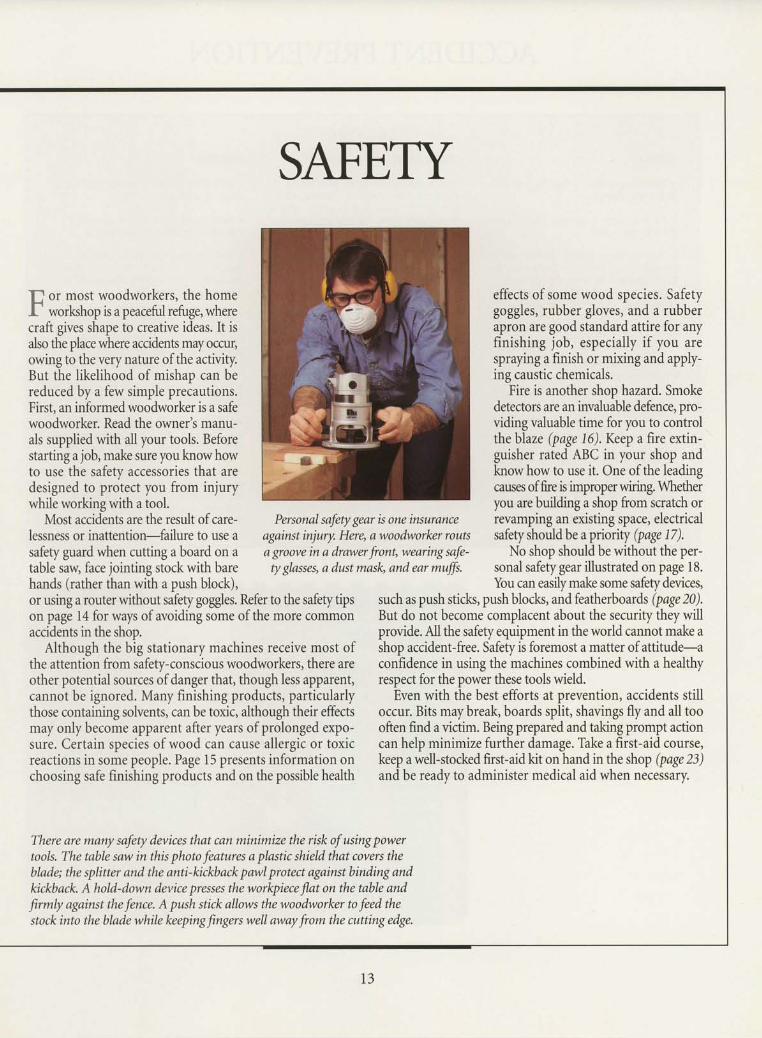
Personal safety gear is one insuranceagainst injury. Here, a woodworker routsa groove in a dra"wer front, wearing safe-ty gJasses, a dust maslg and ear muffs.
effects of some wood species. Safetygoggles, rubber gloves, and a rubberapron are good standard attire for anyfinishing job, especially if you arespraying a finish or mixing and apply-ing caustic chemicals.
Fire is another shop hazard. Smokedetectors are an invaluable defence, pro-viding valuable time for you to controlthe blaze (page 16). Keep a fire extin-guisher rated ABC in your shop andknow how to use it. One of the leadingcauses offire is improperwiring. Whetheryou are building a shop from scratch orrevamping an existing space, electricalsafety should be a priority (page 17).
No shop should be without the per-sonal safety gear illustrated on page 18.You can easilymake some safetydevices,
i
It -
IIl _
or using a router without safety goggles. Refer to the safety tipson page 14 for ways of avoiding some of the more commonaccidents in the shop.
Although the big stationary machines receive most ofthe attention from safety-conscious woodworkers, there areother potential sources ofdanger that, though less apparent,cannot be ignored. Many finishing products, particularlythose containing solvents, can be toxic, although their effectsmay only become apparent after years of prolonged expo-sure. Certain species of wood can cause allergic or toxicreactions in some people. Page 15 presents information onchoosing safe finishing products and on the possible health
such as push sticks, push blocls, and featherboards (page 20).But do not become complacent about the security they willprovide. All the safety equipment in the world cannot make ashop accidentfree. Safety is foremost a matter of attitude-aconfidence in using the machines combined with a healthyrespect for the power these tools wield.
Even with the best efforts at prevention, accidents stilloccur. Bits maybreak, boards split, shavings fly and all toooften find a victim. Being prepared and taking prompt actioncan help minimize further damage. Take a first-aid course,keep a well-stocked first-aid kit on hand in the shop (page 23)and be ready to administer medical aid when necessary.
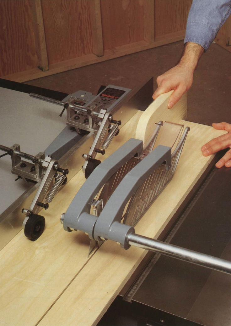
There are many safety devices that can minimize the risk of using powertook. The table san in this photo features a plnstic shield that covers theblade; the splitter and the anti-kickback panl protect against binding andkickback. A hold-down device presses the workpiece flat on the table and
firmly against the fence. A push stick allows the woodnorker to feed thestock into the blnde while keeping fingers well anay from the cutting edge.
t 3
ACCIDENT PREVENTION
GENERAL
r Make sure workshop lighting and venti-lation are adequate.
r Keep children, onlookers, and pets awayfrom the work area.
. Concentrate on the job; do not rush ortake shortcuts. Never work when you aretired, stressed, or have been drinkingalcohol or using medications that induceqrowstness.
. Find a comfortable stance: avoid over-reaching.
r Keep your work area clean and tidy;clutter can lead to accidents.
HAND TOOTS
o Use the appropriate tool for the job;do not try to make a tool do somethingfor which it was not designed.
r When possible, cut away from your-self rather than toward your body.
. Keep tools clean and sharp.
SAFETY TIPS
POWER TOOTS
o Wear appropriate safety gear: safetyglasses or face shield and hearing protec-tion. lf there is no dust collection system,wear a dust mask. For allergenic woods,such as ebony, use a respirator.
. Read your owner's manual carefullybefore operating any tool.
. Tie back long hair and avoid loose-fit-ting clothing. Remove rings and otherjewelry that can catch in moving parts.
. Unplug a tool before performing setupor instal lation operations.
r Whenever possible, clamp down theworkpiece, leaving both hands free toperform an operation.
. Keep your hands well away from a turn-ing blade or bit.
. Turn off a tool if it oroduces an unfa-miliar vibration or noise: have the toolserviced before resuming operations.
o Do not use a tool if any part of it isworn or damaged.
FINISHING
. Do not eai, drink, or smoke when usingfinishing products.
r Avoid exposure to organic solvents ifyou are pregnant or breast-feeding.
. Install at least one smoke detector onthe ceiling of your shop above potentialf ire hazards; keep a fully charged ABCfire extinguisher nearby.
r Never store solvents or chemicals inunmarked containers. Chemical solutionsshould always be stored in dark glass jarsto shield them from light, which maychange their composition.
o Store finishing products in a lockedcabi net.
oTo prevent eye injury, wear safety gog-gles, and don rubber gloves when workingwith caustic or toxic finishing products.
. Do not flush used solvents down thedrain. Consult the Yellow Pages to findout who handles chemical disoosal inyour area, or check with your local f iredeoartment.
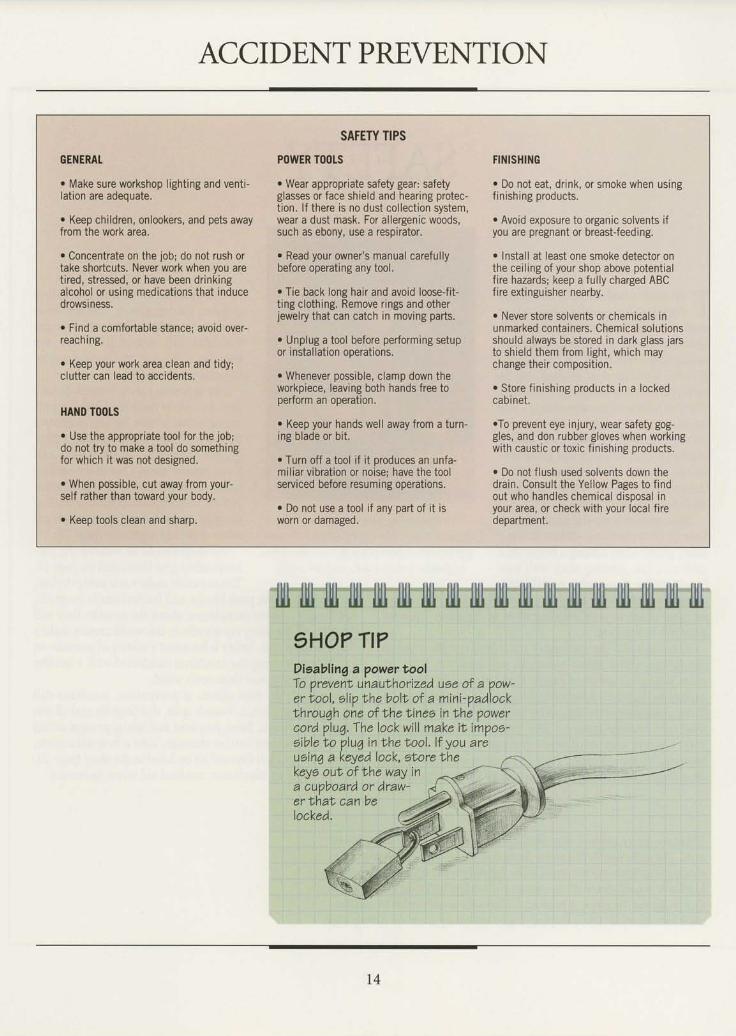
"fl|"ff'lll""1{l"lll"'llll'1lll'lII ill llll'llll'll|l llll llti llll llll trlll IlIl1HO? TI?Disabling a powertoolTo prevent unaulhorized use of a ?ow-er lool, olip lhe boll of a mini-Vadlockthrouqh one of the tinee in lhe power
keye out of vhe way ina cupboard or draw-er thal can belocked.
cord pluq. The lock will make it im?o6-sible to plu6 in trhe trool.lf you areueinq akeyedlock, s lorelhe t
t4
WORKING WITH SAFE FINISHES
I lthough a number of high-qualityA water-based finishes have becomeavailable recently, solvent-based finish-ing products are still widely used, andconsidered superior for some applica-tions. Thus woodworkers must learn toprotect themselves against the healthhazards associated with organic solvents.Organic solvents can have a number ofhealth effects. Short-term use can resultin ailments ranging from headaches andnausea to skin and eye irritation. With
Toxrc soLvENTs
extended use, many solvents are knownto damage the central nervous systemor respiratory tract. Some glycol ethersare suspected ofcausing birth defects,while other solvents,like methylene chlo-ride, have been linked with cardiac arrest.
Solvents can be absorbed into thebloodstream in a number of ways: afterbeing inhaled, or ingested along withfood left in the shop, absorbed throughthe skin, or swallowed when vapors set-tle in saliva. Most solvent-based finish-
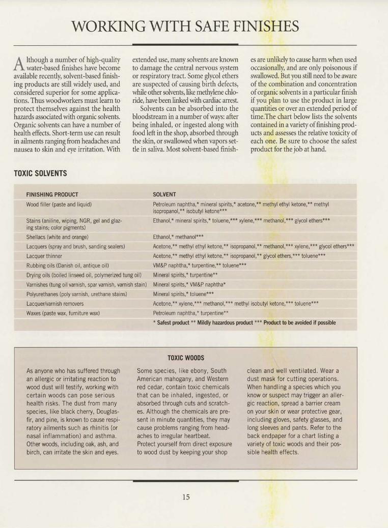
es are unlikely to cause harm when usedoccasionally, and are only poisonous ifswallowed. But you still need to be awareof the combination and concentrationof organic solvents in a particular finishif you plan to use the product in largequantities or over an extended period oftime.The chart below lists the solventscontained in a variety of finishing prod-ucts and assesses the relative toxicity ofeach one. Be sure to choose the safestproduct for the job at hand.
FINISHING PRODUCT
Wood fi l ler (paste and liquid)
Stains (anil ine, wiping, NGR, gel and glaz-ing stains; color pigments)
Shellacs (white and orange)
Lacquers (spray and brush, sanding sealers)
Lacquer thinner
Rubbing oils (Danish oil, antique oil)
Drying oils (boiled l inseed oil, polymerized tung oil)
Varnishes (tung oil varnish, spar varnish, varnish stain)
Polyurethanes (poly varnish, urethane stains)
Laco uer/varn ish removers
Waxes (paste wax, furniture wax)
SOLVENT
Petroleum naphtha,* mineral spirits,* acetone,** methyl ethyl ketone,** methylisopropanol, ** isobutyl ketone***
Ethanol,* mineral spirits,* toluene,*** xylene,*** methanol,*** glycol ethers***
Ethanol,* methanol***
Acetone,** methyl ethyl ketone,** isopropanol,** methanol,*** xylene,*** glycol ethers***
Acetone,** methyl ethyl ketone,** isopropanol,** glycol ethers,*** toluene***
VM&P naphtha,* turpentine,** toluene***
Mineral spirits,* turpentine**
Mineral spirits,* VM&P naphtha*
Mineral spirits,* toluene***
Acetone,** xylene,*** methanol,*** methyl isobutyl ketone,*** toluene***
Petroleum naphtha,* turpentine*** Safest product ** Mildly hazardous product *** Product to be avoided if possible
As anyone who has suffered throughan allergic or irritating reaction towood dust will testify, working withcertain woods can oose serioushealth risks, The dust from manyspecies, like black cherry, Douglas-fir, and pine, is known to cause respi-ratory ailments such as rhinitis (ornasal inf lammation) and asthma.Other woods, including oak, ash, andbirch, can irritate the skin and eyes.
Toxtc w00Ds
Some species, l ike ebony, SouthAmerican mahogany, and Westernred cedar, contain toxic chemicalsthat can be inhaled, ingested, orabsorbed through cuts and scratch-es. Although the chemicals are pre-sent in minute quantities, they maycause problems ranging from head-aches to inegular heartbeat.Protect yourself from direct exposureto wood dust by keeping your shop
clean and wel l vent i lated. Wear adust mask for cutt ing operat ions.When handling a species which youknow or suspect may trigger an aller-gic reaction, spread a barrier creamon your skin or wear protective gear,including gloves, safety glasses, andlong sleeves and pants. Refer to theback endpaper for a chart listing avariety of toxic woods and their pos-sible health effects.
1 5
FIRE SAFETY
/a onsiderins the number of flamma-\-, Ut. rut.ri"ul, and potential ignitionsources in a woodworking shop, fire pre-vention should be one ofyour foremostsafety concerns. Sawdust, wood, paint,and thinners tend to accumulatel oftenthey are near tools that produce sparksand heat. The combinat ion can orovevolat i le: When vaporized in a imal lenough concentraiion of air, a smallquantity of lacquer thinner, for exam-ple, can be ignited by a spark from a tooland cause a life-threatening explosion.
The first step in fire safety is preven-tion. All finishing products and solvents,for example, should be stored away fromheat sources in airtight glass or metalcontainers, preferably in a fireproofcab-inet (page B9). Hang rags soaked withflammable chemicals to dry outdoors,or soak them in water and store them insealed metal containers. When workinewith finishing products, keep windowiopen and the shop well ventilated.
Be prepared to dealwith a fire effec-tively. Install a smoke detector on the
shop ceiling or a wall, and keep an ABCfire extinguisher nearby. Design a fireevacuation plan that maps out two pos-sible escape routes from each room ofthe building in which the shop is locat-ed. Ifthe fire involves an electric tool, apower cord, or an electrical outlet, shutoffthe power. Call the fire departmentimmediately, inform them of the natureof the fire, and try to extinguish the blazeyourself. But if the flames cannot be con-tained, or the fire is coming from insidea wall or ceiling, evacuate the building.
PREPARING AGAINST FIRE
Installing a smoke detectorOpen the cover of the detector, hold the base on thecei l ing or wal l , and mark the screw holes. Bore a holefor a screw anchor at each mark. Tao the anchors intothe holes and, holding the detector in posit ion, dr ivea screw into each anchor to secure the base (right).Install a battery and close the detector cover. Test thedevice once every month. First, press the test button.Then, blow out a l i t match or candle below a vent,letting smoke enter it. Replace the battery if the alarmdoes not sound for both tests-or if it emits a chirpingsound, indicat ing the battery is weak.
Controlling a fireTo ext inguish a smal l , contained f i re, use an ABC-rat-ed dry-chemical f i re ext inguisher, which is effect iveagainst all three major classes of fires: burning wood orother combustibles (Class A), oil- or grease-fed flames(Class B), and electrical blazes (Class C). Position your-self a safe distance from the fire with your back to thenearest exi t . Holding the ext inguisher upright, pul l thelock pin out of the handle ( insef)and aim the nozzle atthe base of the f lames. Squeeze the handle and sprayrn a quick, side{o-side motion (/eff) until the f ire is out.Watch for " f lashback," or rekindl ing, and be preparedto spray again. l f the f i re spreads, leave the bui lding.Dispose of burned waste following the advice of the f iredepartment. After use, have the ext inguisher profes-sionally recharged; replace it if it is non-rechargeable.
T6
ELECTRICAL SAFETY
lectricity plays a major role in themodern woodworking shop, pow-
ering machines and tools, lighting fix-tures and lamps, and heating systems.Electricityis so commonplace that it is alltoo easy to forget is potential for danger.An electrical shock, even one that canhardlybe felt, can be deadly. For this rea-son, the electrical system is strictly reg-ulated by codes and standards designedto protect you from fire and shock.
Living safely with electricity alsorequires following basic precautionsdesigned to prevent mishaps. Inspectplugs for cracks and power cords forfrayrng, and replace any worn or dam-aged part before using a tool. Neverreplace a blown fuse with one of a high-er amperage. Do not plug a three-prongplug into a two-slot outlet by remov-ing the grounding prong from a three-prong plug. Instead, replace the outletwithaGFCI |WA.
Before undertaking a repair, shut offthe oower at the service oanel. To workon the system, wear rubber gloves and,where possible, use only one hand, keep-ing your free hand behind your back.
MINIMUM WIRE GAUGE F(|R EXTENSION CORDS
PLUGGING IN SAFELY
Using GFGI outletsThe U.S. National Electrical Code requires that any new outlet in a garageor unfinished basement must be protected by a ground-fault circuit inter-rupter (GFCI). A GFCI protects a circuit-and you-by monitoring the flow ofelectricity passing through it and tripping instantly when it detects a leak toground. lf you need to replace an outlet in your shop, install a GFCI, such asthe one shown above, followingthe manufacturer's directions, or have a quali-fied electrician do the work. Test the outlet once every month by pushing theTEST button; the RESET button should pop out. lf it does not, have the outletserviced. To reactivate the outlet, press the RESET button.
AMPERAGIRATII{G OF TOOL
o-2.0 18
2,1-3.4 18
3.5-5.0 18
5.1-7 .0 18
7.I-12,0 18
1 2 . 1 - 1 6 . 0 1 6
MINIMUM GAUGE F(lRDIFFERE}IT TENGTH CORDS
25' 50'
18
1 8
1 8
1 6
T4
I 2
Choosing a wire with the proper gaugeUsing an extension cord with the wrong gauge cancause a drop in line voltage, resulting in loss of pow-er. excessive heat. and tool burnout. Refer to thechart at left to determine the minimum wire gaugefor the tool and task at hand. lf, for instance, yourtool has a 7 -amp motor and youlre using a 75{ootextension cord, the minimum gauge should be 14.Choose only round-jacketed extension cords listedby Underwriters Laboratory (UL).
75'
1 8
1 8
1 6
t4
T 2
1 0
t 7

PERSONAL SAFETY GEAR
-f h. personal safety equipment shownI below can go a long way toward
shieldingyou from most dangers in theworkshop. But carrying an inventoryof safety gear is not enough; the itemsmust be properly used to protect youfrom injury.
The need for some items may not bereadily apparent, although the dangers
are very real. Few woodworkers need tobe reminded of the cutting power of aspinning saw blade or jointer cutterhead.Less well known are the long-term effectsofbeing exposed to the sound generatedby power tools. The chart on the nextpage lists a variety of power tools alongwith their approximate noise levels indecibels. The chart also indicates the
Iongest recommended time that anunprotected person can be exposed tovarious levels before risking permanenthearing loss.
Remember, too, that even short-termexposure to some noise, while it maynot lead to hearing loss, can dull thesenses and cause a woodworker's alert-ness to flag-a setup for an accident.
A PAI{OPIY OF SAFETY EOUIPMENT5afety goggleeFlexible, molded plaati" f,:6o6qleo protect eyee. lliType with perforated vani \holea ehielda aqainat impactinjury and sawduat; type withbaffled vents protecto a7ainotahemi cal apl a eh e a: n o nvent edqoq7lea albo available.
Faae shieldClear plaatic ahield pro-tecta a4ainat. flyinq debriaand eplaahea; featureaadjuetable head 4ear
Work glovesFor handlinq rouqhlumben typically fea-turee leather or thickfabrio palmo and finqer-tipe with elaaticized orknitted wrists
for one-ti me- uoe protec-tion aqainet inhaiation ofduat or miaX featurea acotton or fiber shield withan adjuotable head atrapand a metal noee olip
Rubber gloveaHouaehold rubbergloveo or dieposablevinyl qloveo protectaqainot mild chemicalsor finishea; neoprene rub-ber alovea shield akinfrom cauetic finiahinqProducto
Ear muffsCuahioned muffa withadiuetable plaatic headeirap protbct hearinqagainot hi1h -intenaitynoiae from power toola
D u a l - aa ftri dg e re s pi rato rFrotecta aqainet fumea when workin4with chemicala or aprayinq a finiah.lnterchanqeable filtera and chemicalcartridqee ehield aqainat opecific haz-ards; filter prevents inhalation of dust.Cartridqea purify air and expel toxinath rough exhalation valve
Ear plugs with neakband
Reuaable duat maskFeatures a neoprene rubberor aoft plaatii frame withan adjubtable head etrapand a replaceable cottonfiber or 7auzefiltec protecteagainet duet and misL
Detachable foam-rubber pluqa compreooedand inaerted into ear canals provide hearinqprotection from high-inteneity power toolnoiae; plaatic neckband fits around neck
2afetyglaeeee j I
?;f:lT,if'tr:;i::fT:f \leneee proteot eyeb from flyinqwood chipo and other debris:t.ypically feature aide ahielda
t 8

SAFETY
MACHII{E SOUND IEVELS *
1%-Hf router
1 1 5
112
I09
2-HF circular eaw
l-HP router
%.-HP radial arm
%-HP ioi
%-HF router
%-HP band
2-HF ahaper2-HP table aaw
%-HF drill preao
* Higheet decibel ratingwhile cutting hardwood
Occupational )afety a n dHealih Adminiat.rat'ion(OAHA) atandarda forpermi a oibl e n oiae exp oeu rewitho ut h ea ri n4 p rotec'tio n
Sound levelin decibela
Maximumoafe expooureper day (hr)
NOISE LEVELS PR(IDUCED BY POWER T(|(ILS
While a %-horsepower drill press is unlikely to damage your hearing-unless you run the machine all daylong-unprotected exposure to the noise produced by a 1 %-horsepower router can be dangerous after only30 minutes. The above chart shows approximate noise levels produced by a variety of power tools. Keep inmind that tools with dull cutters or blades generate more noise than those with well-sharpened cutting edges.
TESTING A RESPIRATOR
Checking for air leaksA respirator is only as good as its seal against your face. Noseal, no protection. To test your respirator, place it over yourface, setting the top strap over the crown of your head. Adjustthe side straps for a snug fit. To test the respirator, cover theoutlet valve with your hand and breathe out gently (right).Thereshould be no air leakage around the facepiece. lf air leaks outof the respirator, readjust the straps for a tighter fit. Replacethe facepiece when necessary following the manufacturer'sinstructions, or replace the respirator. Use the appropriate fil-ters for the job at hand. (lf you have a beard, use a full-facemask with forced-air venti lation.)
,.+s\N\\,$ ;
{ / f l \ /
I 9
SAFETY
A VARIETY ()F PUSH STICK DESIGNS
12" -
12" '
PUSH STICKSPush sticks for feeding stock acrossstationary tool tables can be pur-chased ready-made, but they areeasy to make in the shop using %-inch plywood scraps and a band sawor saber saw. The variations shownabove can serve as rough guides, butno one shape is ideal for every situa-tion. Design a push stick that is com-fortable to hold and suited to themachine and ooeration at hand. Thelong base of a rectangular push stick(above, left) or shoe-shaped model(above, right)allows you to applyfirm downward pressure on a work-piece. Either design wi l l ef fect ivelykeep your hands away from a bladeor cutter while pushing narrow stockacross a saw table.
For most cuts on a table saw, designa push stick with a 45' angle betweenthe handle and the base (above, cen-fer.). A push stick featuring a smallerangle, with the handle closer to thetable, works better for ripping wood
on a radial arm saw. Whatever designyou choose, the notch on the bottomedge must be deep enough to supportthe workpiece, but shal low enoughnot to contact the machine table. Youcan also chamfer the edges of thehandle for a more comfortable grip.
Keep your push sticks close at hand,ready to feed stock when necessary.
To use a push st ick on a radial armsaw (below), set it against the trail-ing end of the workpiece and feedit into the blade; at the same t ime,apply some side pressure to keepthe stock f lush against the fence.When the cut is completed, retractthe push st ick careful ly to preventi t f rom catching in the blade.
20
SAFETY
PUSH BTOCK
A PUSH BLOCK FOR FACE JOINTINGThe long, wide base of the push blockshown above is ideal for surfacing theface of a board on a jointer. Althoughpush blocks for such jobs are availablecommercial ly, you can easi ly fashion
your own. Refer to the illustration forsuggested dimensions, but tai lor thedesign to suit your own needs.
Cut the pieces to size, then glue thelip to the underside of the base, flushwith one end. Screw the handle to the
top, positioning it so the back is evenwith the end of the base. Drive thescrews from the underside of the base;be sure to countersink the fasteners toavoid marring the workpiece when youfeed it across the jointer knives. Bore ahole near the front end of the base soyou can hang the push block on thewal l when i t is not in use.
To use the push block, set the work-piece on the jointer 's infeed table afew inches from the knives, butt ingits edge against the fence. Then laythe push block squarely on top of thestock, centered between its sides, withthe l ip over the trai l ing end of theworkpiece. With your leading handon the front end of the stock and yourthumb braced against the push block,slowly feed the workpiece across theknives (/efil. (For stock thinner than3/a inch, use only the push block.) Applydownward pressure to keep the stockflat on the tables and lateral Dressureto keep it butted against the fence.
2 I
SAFETY
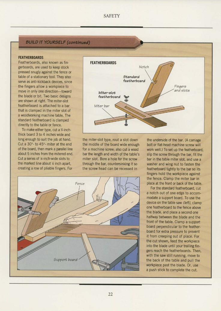
FEATHERBOARDSFeatherboards, also known as fin-gerboards, are used to keep stockpressed snugly against the fence ortable of a stationary tool. They alsoserve as anti-kickback devices, sincethe f ingers al low a workpiece tomove in only one direction-towardthe blade or bit. Two basic designsare shown at right. The miter-slotfeatherboard is attached to a barthat is clamped in the miter slot ofa woodworking machine table. Thestandard featherboard is clampeddirectly to the table or fence.
To make either type, cut a %-inch-thick board 3 to 4 inches wide andlong enough to suit the job at hand.Cut a 30"- to 45o- miter at the endof the board, then mark a parallel lineabout 5 inches from the mitered end.Cut a series of X-inch-wide slots tothe marked line about 1l inch aoart,creating a row of pliable fingers. For
the miter-slot type, rout a slot downthe middle of the board wide enoughfor a machine screw; also cut a woodbar the length and width of the table'smiter slot, Bore a hole for the screwthrough the bar, countersinking it sothe screw head can be recessed in
FEATHERB()ARDS
9tandardfeatherboard
the underside of the bar. (A carriagebolt or flat-head machine screw willwork well.) To set up the featherboard,slip the screw through the bar, fit thebar in the table miter slot, and use awasher and wing nut to fasten thefeatherboard tightly to the bar so itsf ingers hold the workpiece againstthe fence. Clamp the miter bar inplace at the front or back of the table.
For the standard featherboard, cuta notch out of one edge to accom-modate a support board. To use thedevice on the table saw (/eftl, clampone featherboard to the fence abovethe blade, and place a second onehalfway between the blade and thefront of the table. Clamp a supportboard perpendicular to the feather-board for extra pressure to preventi t f rom creeping out of place. Forthe cut shown, feed the workpieceinto the blade until your trailing fin-gers reach the featherboards. Then,with the saw still running, move tothe back of the table and pul l theworkpiece past the blade. 0r, usea push stick to complete the cut.
22
FIRSTAID
ost woodworking accidents arisefrom the improper use of tools
and safety guards, unsafe work habits,and mishandling hazardous materials.Thke the time to set up properly for ajob, gathering together the tools, equip-ment, and materials you need. Alwaysuse the appropriate safety gear. Workmethodically; never hurry through a job.
Be especially carefrrl-or stop working-ifyou are fatigued.
Accidents can befall even the mostcarefirl woodworker. Boards split, bladesnick, and liquids splash. Many finishingproducts contain chemicals that emitioxic fumes, causing dizziness or nau-sea. Keep in mind the potential hazardsof anv tool or material vou use. Store a
first-aid kit, stocked with the basic sup-plies shown below, in an easily accessiblespot in your shop. In the event ofan acci-dent, you will want anyone to be able tofind it quickly to administer first aid.Keep emergency telephone numbershandy. Techniques for handling somecommon shop mishaps are shown onthe following pages.
FIRST.AID SUPPTIES
Tweezera
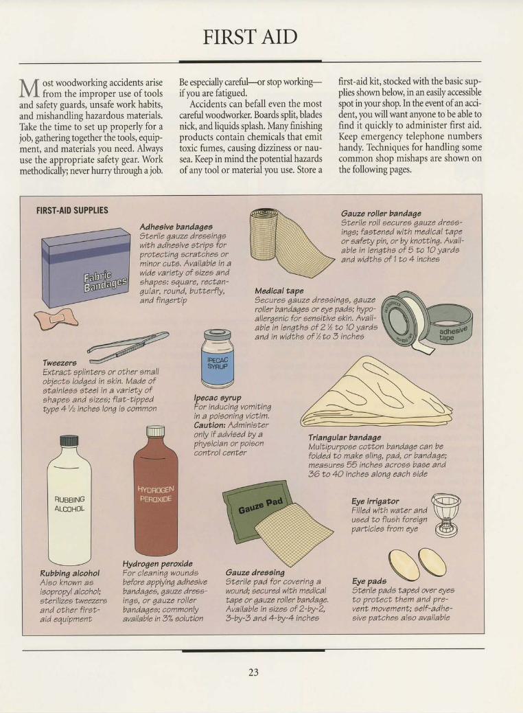
Rubbing alaoholAlao known aaiaopropyl alcohol:aterilizea tweezeroand other firat'aid equipment
Adheaive bandagea)terile 4auze dreeeinqowith adheaive atripa forprotecting acratchea orminor cuta. Available in awide variety of sizes andahapes: gquare, rectan'qutAr, rouid, butterfty,and finaerbip
Oauze roller bandageOtedle roll oecurea qauze dreoa-inga; faotened with medical tapeor aafety pin, or by knottinq. Avail-able in lenqtha of 5 to 10 yardoand widtha of 1 to 4 inchea
Medical tape)ecurea qauze dreeein7a, 1auzeroller bandaqes or eye pada: hypo-aller4enic for aenaitive akin. Avail'able in lenqtha of 2 % to 10 yardaand in widths of %to 5 inches
Extract eplintera or other emallobjecto lod7ed in akin. Made ofetainlese steel in a variety ofohapee and aizea; flat-tippedtype 41/z inchea lon7 ie common
Ipeaaa eyrupFor inducin7 vomitinqin a poiaoning victim.Caution: Administeronly if advieed by aphyeician or poiaoncontrol center
Triangular bandageMultipurpoee cotton banda7e can befolded to make alin4, pad, or bandaqe;meaeurea 55 inchea acroeo baoe and36 to 40 inchea alona each aide
Eye irrigatorFilled with water andueed to fluah foreiqnparticleo from eye
Hydrogen peroxideFor cleaninq woundsbefore applyinq adheoivebanda7ee,1auze dreaa'inga, or qauze roilerbandaqea; aommonlyavailable in 3% aolution
Gauze dreeaing)terile pad for coverin7 awound; becured with medicaltape or qauze roller bandaqe.Available in aizes of 2-by-2,3-W-3 and 4-by-4 inchea
r\r\\ \ \ )
Eye pada \-'l)terile pado taped over eyeeto protect them and pre-vent movement: aelf-aane-oive patchea alao available
23
SAFETY
PROVIDING MINOR FIRST AID
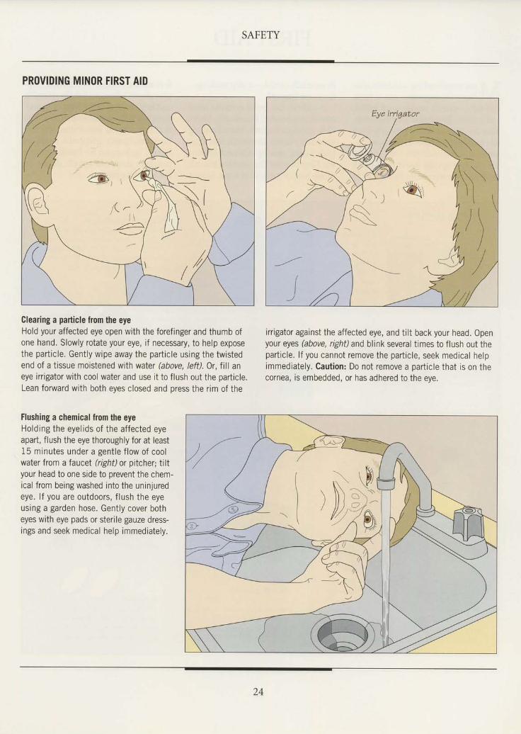
Clearing a pailicle from the eyeHold your affected eye open with the forefinger and thumb ofone hand. Slowly rotate your eye, if necessary, to help exposethe particle. Gently wipe away the particle using the twistedend of a tissue moistened with water (above, left). Or, till aneye irrigator with cool water and use it to flush out the particle.Lean forward with both eyes closed and press the rim of the
irrigator against the affected eye, and tilt back your head. Openyour eyes (above, right) and blink several times to flush out theparticle. lf you cannot remove the particle, seek medical helpimmediately. Caution: Do not remove a particle that is on thecornea, is embedded, or has adhered to the eye.
/ / J
Flushing a chemical fiom the eyeHolding the eyelids of the affected eyeapart, flush the eye thoroughly for at least15 minutes under a gentle flow of coolwater from a faucet (right) or pitcher; tiltyour head to one side to prevent the chem-ical from being washed into the uninjuredeye. lf you are outdoors, flush the eyeusing a garden hose. Gently cover botheyes with eye pads or sterile gauze dress-ings and seek medical help immediately.
24
SAFETY
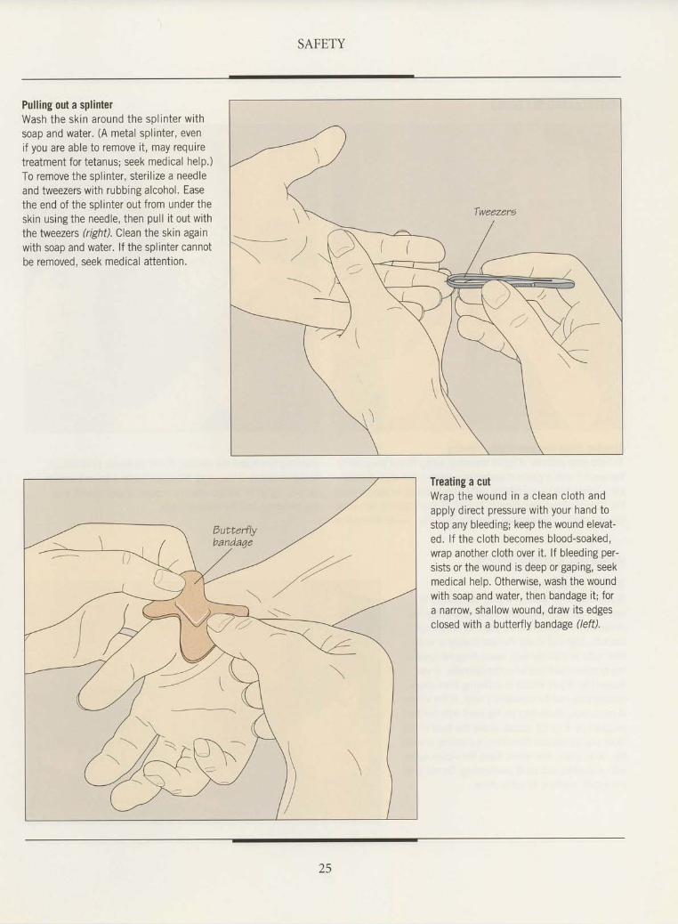
Pulling out a splinterWash the skin around the sol inter withsoap and water. (A metal splinter, evenif you are able to remove it, may requiretreatment for tetanus; seek medical help,)To remove the splinter, sterilize a needleand tweezers with rubbing alcohol. Easethe end of the splinter out from under theskin using the needle, then pull it out withthe tweezers (right). Clean the skin againwith soap and water. lf the splinter cannotbe removed. seek medical attention.
Treating a cutWrap the wound in a clean cloth andapply direct pressure with your hand tostop any bleeding; keep the wound elevat-ed. lf the cloth becomes blood-soaked,wrap another cloth over it. lf bleeding per-sists or the wound is deep or gaping, seekmedical help. Otherwise, wash the woundwith soap and water, then bandage it; fora narrow, shallow wound, draw its edgesclosed with a butterfly bandage (left).
25
SAFETY
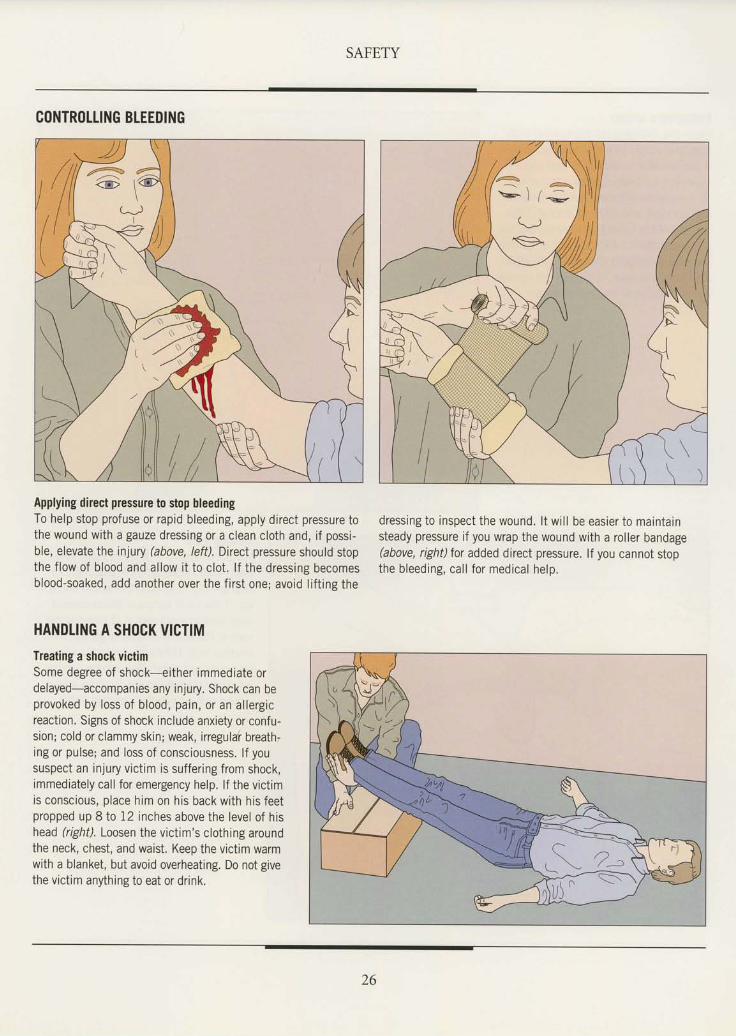
CONTROTLING BLEEDING
Applying direct pressure to stop bleedingTo help stop profuse or rapid bleeding, apply direct pressure tothe wound with a gauze dressing or a clean cloth and, if possi-ble, elevate the injury (above, left). DiecI pressure should stopthe f low of blood and al low i t to clot . l f the dressing becomesblood-soaked, add another over the f i rst one; avoid l i f t ing the
dressing to inspect the wound. l t wi l l be easier to maintainsteady pressure if you wrap the wound with a roller bandage(above, right) tor added direct pressure. lf you cannot stopthe bleeding, cal l for medical help.
4 = ,@ \
HANDTING A SH(ICK VICTIMTreating a shock victimSome degree of shock-ei ther immediate ordelayed-accompanies any injury. Shock can beprovoked by loss of blood, pain, or an al lergicreaction. Signs of shock include anxiety or confu-sion; cold or clammy skin; weak, iregular breath.ing or pulse; and loss of consciousness. lf yoususpect an injury victim is suffering from shock,immediately call for emergency help. lf the victimis conscious, place him on his back with his feetpropped up 8 to 12 inches above the level of hishead (right). Loosen the victim's clothing aroundthe neck, chest, and waist. Keep the victim warmwith a blanket, but avoid overheating. Do not givethe victim anything to eat or drink.
26
SAFETY
TREATING A VICTIM OF ELECTRICAL SHOCK
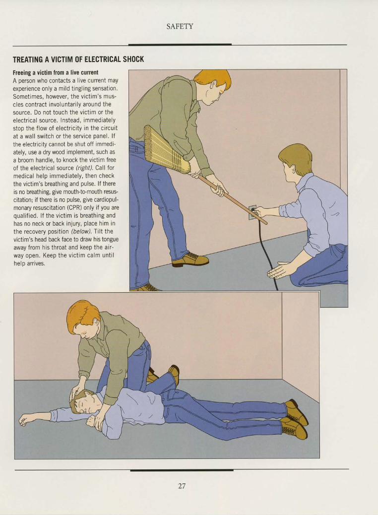
Freeing a victim from a live currentA person who contacts a live current mayexperience only a mi ld t ingl ing sensat ion.Sometimes, however, the vict im's mus-cles contract involuntar i ly around thesource. Do not touch the vict im or theelectr ical source. lnstead, immediatelystop the f low of electr ic i ty in the circui tat a wal l switch or the service panel. l fthe electr ic i ty cannot be shut off immedi-ately, use a dry wood implement, such asa broom handle, to knock the vict im freeof the electrical source (right). Call Iormed ica l he lp immedia te ly , then checkthe vict im's breathing and pulse. l f thereis no breathing, give mouth-to-mouth resus-citation; if there is no pulse, give cardiopul-monary resuscitatton (CPR) only if you arequa l i f ied . l f the v ic t im is b rea th ing andhas no neck or back injury, place him inthe recovery posit ion (below). Tt l t thevictim's head back face to draw his tongueaway from his throat and keep the air-way open. Keep the v ic t im ca lm unt i lhelo arr ives.
27
t"tr,,,
{ -r." \. . \
; r f ,
''a*6*"'n'
\,9
. G
*-
i
s they gain experienceand accumulate tools.
most woodworkers pine fortheir own special place topractice their skills. In theirfantasies, the workshop is anairy space equipped with a sub-stantial workbench and anarrav of stationarv machinesand portable tools. The realityfor many woodworkers, how-ever, is much more modest.The typical shop never seemsto have enough light, power, orelbow room.
Fewhomes have space specif-ically designed as a workshoparea. As a result, setting up ahome shop demands creativity and flexibility; the task ofteninvolves converting an arcaoriginally intended for some oth-er purpose. With careful planning and forethought, however,a location that might appear unsuitable can be turned into anefficient, comfortable place to work.
Although size is often the first consideration, several otherconcerns may be more important. For example, situating ashop in a spare room on the main floor of a home may providea large working area, but noise and dust from tools wouldprobably inconvenience other members of the family. To suittheir own needs without intruding too much on the peopletheylive with, woodworkers commonlylocate home shops in
SHOPIAOI-]T
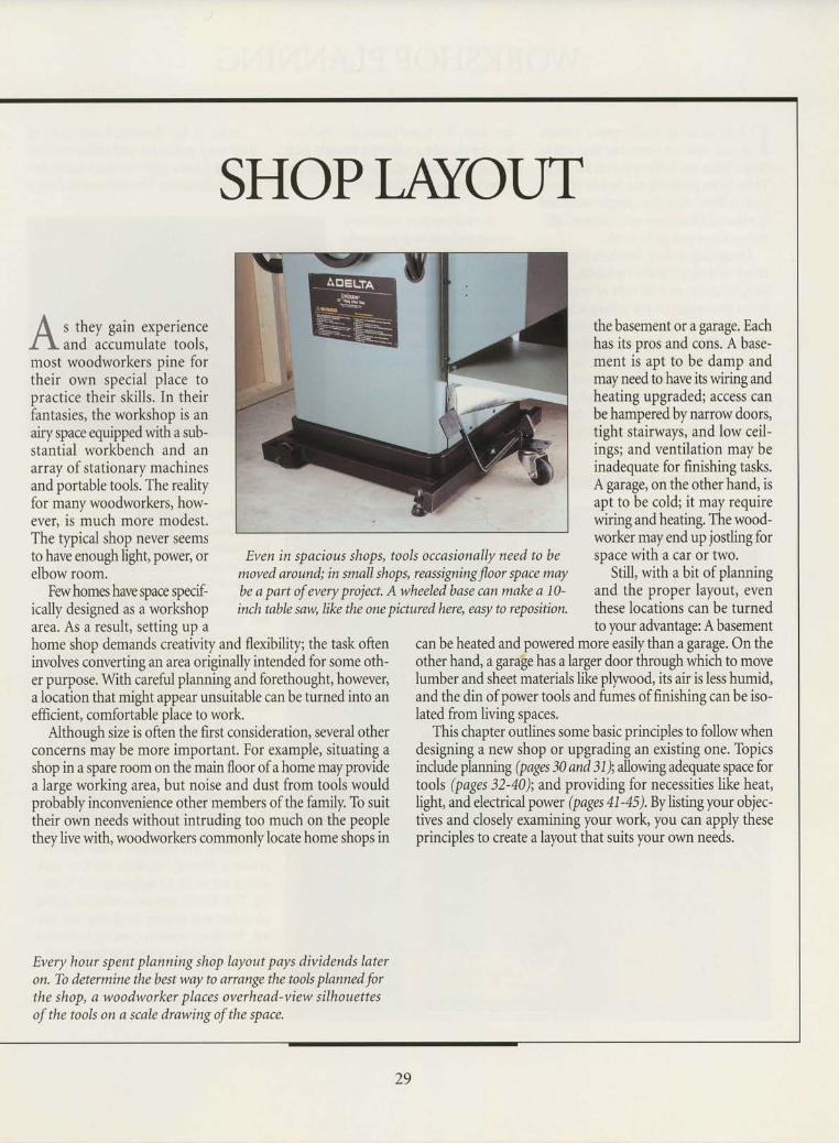
Even in spacious shops, tools occasionally need to bemoved around; in small shopl reassigning floor space maybe a part of every project. A wheeled base can make a 10-inch table saw, like the one pictured here, easy to reposition.
the basement or a garage. Eachhas its pros and cons. A base-ment ii apt to be damp andmay need to have its wiring andheating upgraded; access canbe hampered by narrow doors,tight stairways, and low ceil-ings; and ventilation may beinadequate for finishing tasks.A garage, on the other hand, isapt to be cold; it may requirewiring and heating. The wood-worker may end up jostling forspace with a car or two.
Still, with a bit of planningand the proper layout, eventhese locations can be turnedto your advantage: A basement
can be heated and powered more easily than a garage. On theother hand, a garage has a larger door through which to movelumber and sheet materials like plpvood, its air is less humid,and the din of power tools and fumes of finishing can be iso-lated from living spaces.
This chapter outlines some basic principles to followwhendesigning a new shop or upgrading an existing one. Topicsinclude plannng (pages 30 and 3l);allowing adequate space fortools (pages 32-40); and providing for necessities like heat,light, and electrical power (pages 41-45). By listing your objec-tives and closely examining your work, you can apply theseprinciples to create a layout that suits your own needs.
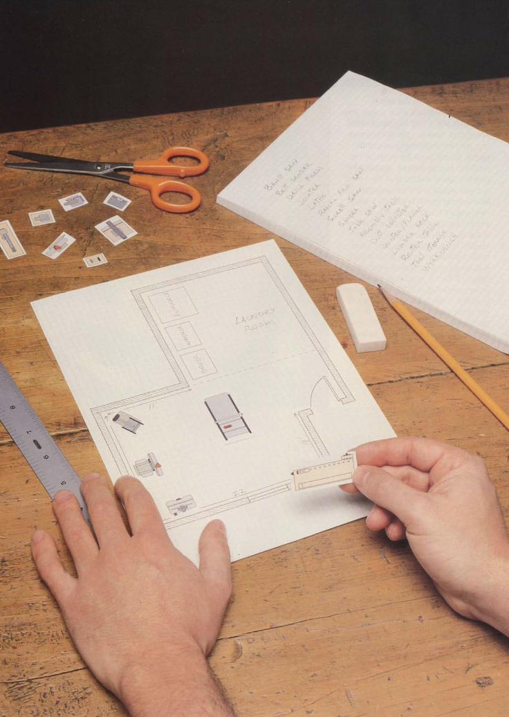
Every hour spent planning shop layout pays dividends lateron. Tb determine the best way to arrange the tools planned forthe shop, e woodworker places overhead-view silhouettesof the tools on a scale drawing of the space.
29
WORKSHOP PLANNING
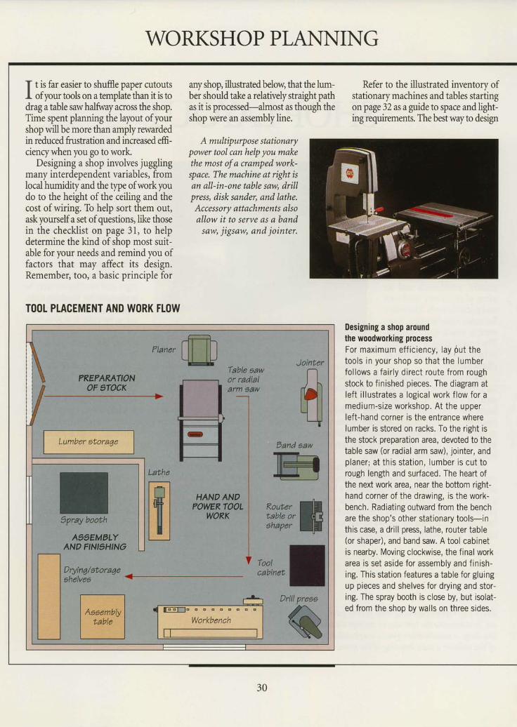
I t is far easier to shuffle paper cutoutsI of vour tools on a template than it is todrag a table saw halfwayicross the shop.Time spent planning the layout of yourshop will be more than amply rewardedin reduced frustration and increased effi-ciency when you go to work.
Designing a shop involves jugglingmany interdependent variables, fromlocal humidity and the qpe of work youdo to the height of the ceiling and thecost of wiring. To help sort them out,ask yourselfa set ofquestions, like thosein the checklist on page 31, to helpdetermine the kind of shoo most suit-able for your needs and remind you offactors that may affect its design.Remember, too, a basic principle for
T()OI PLACEMENT AND WORK FLOW
any shop, illustrated below, that the lum-ber should take a relatively straight pathas it is processed-almost as though theshoo were an assemblv line.
A multipurp o s e statio narypower tool can help you makethe most of a cramped work-space. The machine at right isan all-in-one table sew, drillpress, disk sander, and lathe.Acces sory attachments alsoallow it to serve as a band
saw, j igsaw, and jointer.
Refer to the illustrated inventory ofstationary machines and tables startingon page 32 as a guide to space and light-ing requirements. The best way to design
Designing a shop aroundthe woodworking processFor max imum ef f i c iency , lay Out thetoo ls in your shop so tha t the lumberfollows a f aily direct route from roughstock to f inished pieces. The diagram atlef t i l lustrates a logical work f low for amedium-size workshop. At the upperlef t-hand corner is the entrance wherelumber is stored on racks. To the right isthe stock preparation area, devoted to thetable saw (or radral arm saw), jo inter, andp laner ; a t th is s ta t ion , lumber i s cu t torough length and surfaced. The heart ofthe next work area, near the bottom right-hand corner of the drawing, is the work-bench. Radiating outward from the benchare the shop's other stationary tools-inthis case, a drill press, lathe, router table(or shaper), and band saw. A tool cabinetis nearby. Moving clockwise, the f inal workarea is set aside for assembly and f in ish-ing. This station features a table for gluingup pieces and shelves for drying and stor-ing. The spray booth is close by, but isolat-ed from the shop by walls on three sides.
Lumber gtoraqeDand saw
lxH'€_-J
Wi,ftIzil,",t
30
SHOP LAYOUT
the layout is to experiment with arrang-ing photocopies of scale drawings ofthe tools (page 35) on a sheet ofgraphpaper. Remember that a tool should beoositioned so that an access door is vis-ible from it. In addition, a workpiecekicked back from the tool should notbe able to strike someone working atanother station.
Consider dedicating spaces for spe-cific woodworking tasls. A finishing areaor spray booth requires priority in plan-ning because of light, temperature, andventilation needs.
Depending on the extent of your shopand local zoning and building codes, youmay need to obtain permits; consultyour local building inspection office.
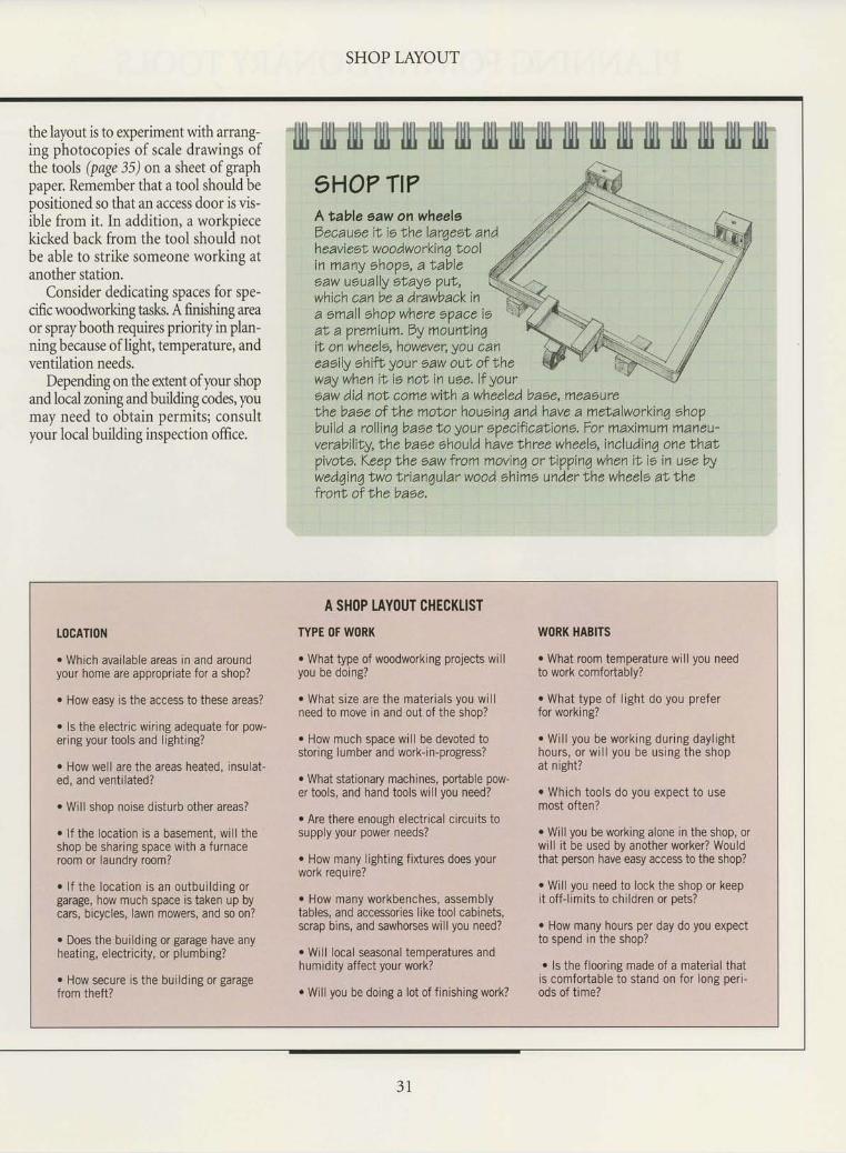
illl tllt l|lt llll ljrl llll llll rlll lllj llll llrl llll llll illl lllj llll llll rll11HO? Tt?Atable eaw on wheelsDecause iI is Lhe larqeot, andhe aviesl w oo dworkin q No olin many ohopo, a Iableoaw uoually etaye pul,which can be a drawbackina emall ohop where epace ieat, a premium. By mountingil on wheels, however, you caneaeily ehifl your 6aw out of theway when it is not in uee.lf yoursaw did nol come with a wheeled baee, measurelhe base of the moNor houeinq and have a melalworkin4 ohopbuild a rollinq baoe lo your epecificaf,ions, For maximuftl trlafitau-verability, the base ehould have lhree wheels, includinq one lhaLpivoNe. Keep Ihe saw from moving or tiVping when iN ie in uee bywedqinq two Irianqular wood ehime under the wheels al lhefront of the baee.
TOGATION
o Which available areas in and aroundyour home are appropriate for a shop?
o How easy is the access to these areas?
. ls the electric wiring adequate for pow-ering your tools and lighting?
. How well are the areas heated, insulat-ed, and ventilated?
r Will shop noise disturb other areas?
. lf the location is a basement, wil l theshop be sharing space with a furnaceroom or laundry room?
. l f the locat ion is an outbui ld ing orgarage, how much space is taken up bycars, bicycles, lawn mowers, and so on?
. Does the building or garage have anyheating, electricity, or plumbing?
o How secure is the building or garagefrom theft?
A SHOP TAYOUT CHECKLIST
TYPE OF WORK
. What type of woodworking projects willyou be doing?
o What size are the materials you wil lneed to move in and out of the shop?
' How much space will be devoted tostoring lumber and work-in-progress?
r What stationary machines, podable pow-er tools, and hand tools wil l you need?
. Are there enough electrical circuits tosupply your power needs?
o How many lighting fixtures does yourwork reouire?
. How many workbenches, assemblytables, and accessories like tool cabinets,scrap bins, and sawhorses will you need?
. Will local seasonal temperatures andhumidity affect your work?
. Will you be doing a lot of f inishing work?
WORK HABITS
r What room temperature will you needto work comfortably?
. What type of l ight do you preferfor working?
r Wi l l you be work ing dur ing dayl ighthours, or wi l l you be us ing the shopat night?
o Which tools do you expect to usemost often?
. Will you be working alone in the shop, orwill it be used by another worker? Wouldthat person have easy access to the shop?
o Will you need to lock the shop or keepit off-l imits to children or pets?
o How many hours per day do you expectto spend in the shop?
r ls the flooring made of a material thatis comfortable to stand on for long peri-ods of t ime?
31
TABTEsAw
PLANNING FOR STIIfIONARY TOOLS
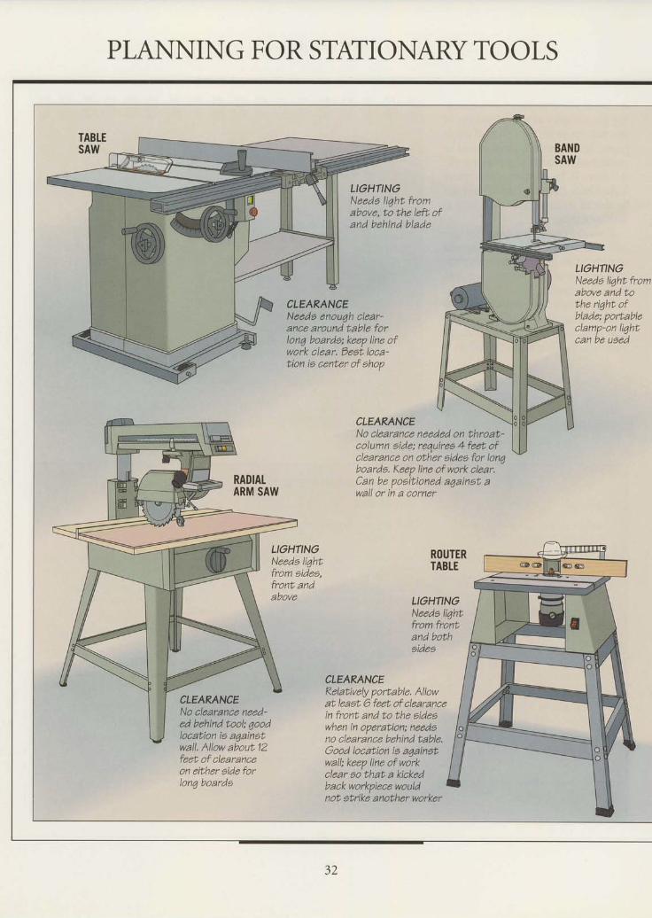
LIOHTINGNaeda liqht fromabove, to the laft ofand behind blade
CLEARANCENeeda enouqh clear-ance around table forlon6 boarde; keep line ofwork clear. Best loca-tion ia center of ahop
CLEARANCE
LIGHNNANeede liqht. fromabove and tothe riqht ofblade; porLableclamp-on li7htcan be uaed
RADIATARM SAW
No clearance needed on throat-column aide; requirea 4 feet ofclearance on other aidee for lonqboarda. Keep line of work alear.Can be poeitioned aqainat awall or in a corner
LIOHTINONeeda li7htfrom aides,front andabove
ROUTERTABTE
LIOHTINGNeeda liqhtfrom frontand bothaides
CLEARANCE
CLEARANCENa clearanae need-ed behind tool; qoodlocation ia againatwall. Allow about 12feet of clearanceon either eide forlong boarde
Relatively portable. Allowat leaat 6 fert of clearancein front and to the aideswhen in operation; needono clearance behind table.Good location ie aqainetwall: keep line of workclear so that a kiakedback workpiece wouldnot. atrike another worker
32
DRITLPRESS
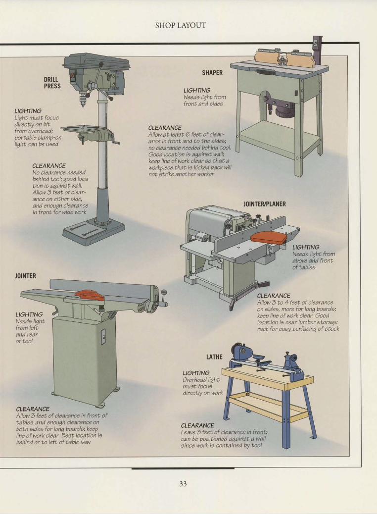
LIOHTINGLiqht muat focuadirectly on bitfrom overhead;portable clamp-onIiqht can be uaed
CLEARANCENo clearance neededbehind toob qood loca'tion ia aqainet wall,AIIow 3 feet of clear-ance on either aide,and enou4h clearancein front for wide work
LIGHTINONeeda liqhtfrom lefLand rearof tool
CLEARANCEAllow 3 feet of clearance in front oftablea and enouqh clearance onboth aidea for long boarde; keepline of work clear. Dest location iebehind or to [ef, of table eaw
SHOP LAYOUT
SHAPER
LIGHTINGNeeda light fromfronL and aidea
CLEARANCEAllow at leaat 6 feet of alear-ance in front and to the sides:no clearance needed behind tool.Good location is aqainat wall;keep line of work clear ao that aworkpiece that ie kicked back willnot atrike another worker
JOINTEUPTANER
LIOHTINONeeda lightfromabove and frontof tablea
CLEARANCEAllow 3 to 4 feet of clearanceon aidea, more for lonq boarde;keep line of work clear. Goodlocation ta near lumber atoraqerack for eaey aurfacin4 of atock
TATHE
LIOHTING)verhead li4htmuat focuadirectly on work
CLEARANCELeave 3 feet of clearance in front:can be poaitioned a7ainet a wallaince work is contained bv tool
JOINTER
33
SHOP LAYOUT
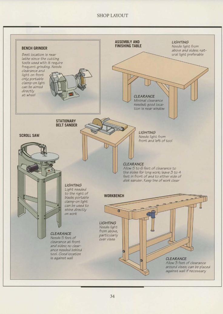
BENCH GRINDER
Deet. location ia nearlathe aince the cuttingtoola ueed with it requirefrequenL 4 ri ndi nq. N eed aclearance andli4ht on frontonly; porEableclamp-on lightcan be aimeddirectlyat whee[
ASSEMBLY ANDFINISHING TABTE
LIGHTINGNeede liqht fromabove and aidea: nat-ural li4ht preferable
CLEARANCEMinimal clearanceneeded; qood loaa-tion ie near window
STATIONARYBEtT SANDER
scR0lt sAwLIOHTINONeede liqht fromfront and left of tool
CLEARANCEAllow 5 to 6 feet of clearance tobhe aidea for lon4 work; leave 3 to 4feet in front of and to either side ofdiak aander. Keep line of work clear
LIOHTINOLi4ht neededto the riqht. ofblade; portableclamp-on lightcan be uoed toehine directlyon work
WORKBENCH
CLEARANCENeeda 5 feet ofclearance at frontand eidea; no alear-ance needed behindtool. Oood locationie a4ainot wall
LIGHTINGNeeda li4htfrom above,parLicularlyover viaeo
CLEARANCEAllow 3 feet of clearancearound viaea; can be placeda4ainet wall if neceoear,
34
SHOP LAYOUT
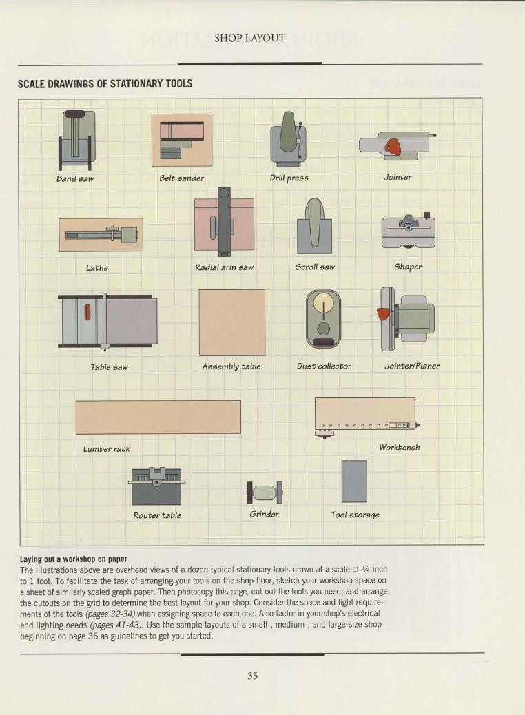
SCATE DRAWINGS OF STATIOI{ARY TOOTS
Laying out a wodtshop on papelThe illustrations above are overhead views of a dozen typical stationary tools drawn at a scale of V+ inchto 1 foot. To facilitate the task of arranging your tools on the shop floor, sketch your workshop space ona sheet of similarly scaled graph paper. Then photocopy this page, cut out the tools you need, and arrangethe cutouts on the grid to determine the best layout for your shop. Consider the space and light require-ments of the tools (pages 32-34) when assigning space to each one. Also factor in your shop's electricaland lighting needs (pages 41-43). Use the sample layouts of a small-, medium-, and large-size shopbeginning on page 36 as guidelines to get you started.
35
SHOP ORGANIZATION
LAYOUT OF A SMALL SH()P
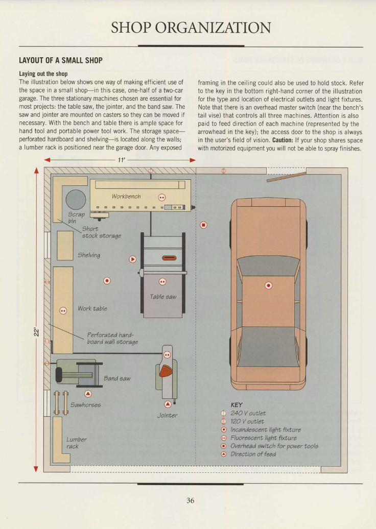
Laying out the shopThe i l lustrat ion below shows one way of making eff ic ient use ofthe space in a smal l shop-in this case, one-half of a two-cargarage. The three stationary machines chosen are essential formost projects: the table saw, the jointer, and the band saw. Thesaw and jointer are mounted on casters so they can be moved ifnecessary. With the bench and table there is ample space forhand tool and portable power tool work. The storage space-perforated hardboard and shelving-is located along the walls;a lumber rack is positioned near the garage door. Any exposed
atock atoraqe
thelvinq
e
Work table
Ferforated hard-board wall etoraqe
Dand aaw
eJointer
f raming in the ce i l ing cou ld a lso be used to ho ld s tock . Referto the key in the bottom r ight-hand corner of the i l lustrat ionfor the type and locat ion of electr ical out lets and l ight f ixtures.Note that there is an overhead master swrtch (near the bench'sta i l v ise) tha t con t ro ls a l l th ree mach ines . A t ten t ion is a lsopaid to feed direct ion of each machine (represented by thearrowhead in the key); the access door to the shop is alwaysin the user 's f ie ld of v is ion. Caut ion: l f your shop shares spacewith motor ized equipment you wi l l not be able to spray f in ishes.
KEY24O V outlet12O V outletI ncandescent liqht fixtu reF I uoreecent liqht firtu reOverhead ewitch for power tooleDirection of feed
11 '
r-)t\ _ / 1 .
^ r cscrap Ibin I
\ strort
d b d b ( a )
l l l l vl l l l )awhoreeeq_F q_F
Tt t| | t,mu",
| | racr
tJ
o0oooo
. .y':,"-n": . -?r:
36
SHOP LAYOUT
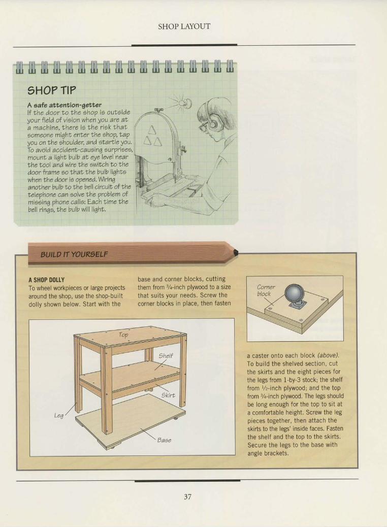
tllt llll fill llll ffi llll llll llll llll llll llll llll llli lllt llll llll llll llll1HO? TI?A s af e att'enti o n - g et t e rl f the door to t 'he ehop is outsideyourf ield ofvieionwhenyou are aIa machine, lhere ie the r iek Ihat 'oomeone miqhl enLer the ehoV,t'apyou on the ehoulder, and etarLle You,Io avoid accident'caueinq ourprioee,mounf, a liqht bulb aI eye level nearthe t ool and wire Nhe swiLch No thedoor frame eo thaLthe bulb liqhtowhenlhe door is oVened,Wirinqano|her bulb to the bell circuiL of Nherelephone can solve the problem ofmis bin a oho n e c alle: E a ih t' im e th ebell rinio,rhe bulb will l iqht.
I\._.2
A SHOP DOLTYTo wheel workpieces or large projectsaround the shop, use the shop-builtdol lv shown below. Start with the
base and corner blocks, cutt ingthem from 3/q-inch plywood to a sizethat sui ts your needs, Screw thecorner blocks in place, then fasten
a caster onto each block (abovd.To bui ld the shelved sect ion, cutthe skir ts and the eight pieces forthe legs from 1-by-3 stock; the shelffrom %-inch plywood; and the toPfrom %-inch plywood. The legs shouldbe long enough for the top to sit ata comfortable height. Screw the legpieces together, then attach theskirts to the legs' inside faces. Fastenthe shelf and the top to the skir ts.Secure the legs to the base withangle brackets.
37
SHOP LAYOUT
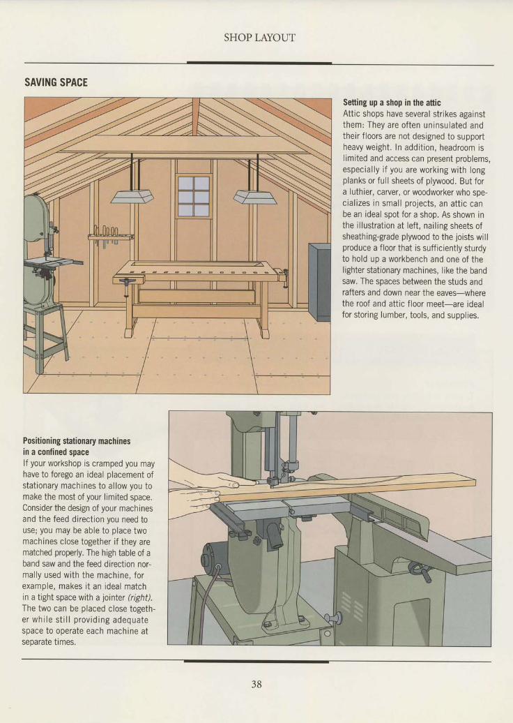
SAVING SPACE
Setting up a shop in the atticAttic shops have several strikes againstthem: They are often uninsulated andtheir f loors are not designed to supportheavy weight. In addit ion, headroom islimited and access can present problems,espec ia l l y i f you are work ing w i th longplanks or full sheets of plywood. But fora luthier, carver, or woodworker who spe-cial izes in smal l projects, an att ic canbe an ideal spot for a shop. As shown inthe i l lustrat ion at lef t , nai l ing sheets ofsheathing-grade plywood to the joists willproduce a floor that is sufficiently sturdyto hold up a workbench and one of thelighter stationary machines, like the bandsaw, The spaces between the studs andrafters and down near the eaves-wherethe roof and attic f loor meet-are idealfor stor ing lumber, tools, and suppl ies.
Positioning stationary machinesin a confined spacelf your workshop is cramped you mayhave to forego an ideal placement ofstat ionary machines to al low you tomake the most of your limited space.Consider the design of your machinesand the feed direct ion you need touse; you may be able to place twomachines close together i f they arematched properly. The high table of aband saw and the feed direction nor-mal ly used w i th the mach ine , fo rexample, makes i t an ideal matchrn a tight space with a jointer (right).The two can be placed close togeth-e r w h i l e s t i l l p r o v i d i n g a d e q u a t espace to operate each machine atseparate times.
38
SHOP LAYOUT
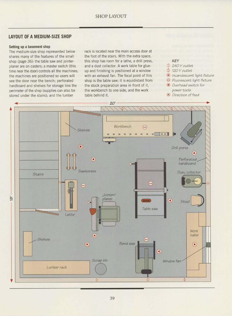
LAYOUT OF A MEDIUM-SIZE SH()P
Setting up a basement shopThe medium-size shop represented belowshares many of the features of the smal lshop (page 36): the table saw and jointer-
olaner are on casters: a master switch (thls
t ime near the door) contro ls a l l the machines;the machines are posi t ioned so users wi l lsee the door near the bench; per foratedhardboard and shelves for s torage l ine theper imeter of the shop (suppl ies can a lso bestored under the sta i rs) ; and the lumber
rack is located near the main access door atthe foot of the sta i rs . Wi th the extra space,th is shop has room for a la the, a dr i l l press,
and a dust co l lector . A work table for g lue-
up and f in ish ing is posi t ioned at a windowwith an exhaust fan. The focal point of th isshop is the table saw; i t is equid is tant f romthe stock preparat ion area in f ront of i t ,the workbench to one s ide, and the worktab le beh rnd i t .
KEY:l 24O V ouLletrl' 12O V outletA lncandeacenL lt4hL ftxl;ureO FluoreecenL ltqhL fixt.ure@ Overhead ewtLch for
power toolo@ Dtrectton of feed
20'
e
thelvee
eSawhoreea
o
Drill prena
e?erforatedhardboard
Duai; collectorilt
Lathe
thelvea
Lumber rack
oe Eand saw
- :o:*".n*- - -? ofr.Er
Jointer/
grrrl[)
39
Window fan
SHOP LAYOUT
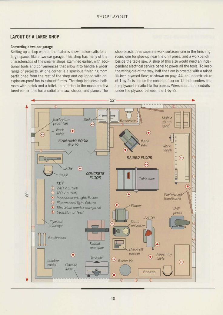
LAYOUT OF A LARGE SH()P
Converting a two-car garageSett ing up a shop with al l the features shown below cal ls for alarge space, like a two-car garage. This shop has many of thecharacter ist ics of the smal ler shops examined earl ier, with addi-t ional tools and conveniences that al low i t to handle a widerrange of projects. At one corner is a spacious f in ishing room,part i t ioned from the rest of the shop and equipped with anexplosion-proof fan to exhaust fumes. The shop includes a bath-room with a sink and a toi let . In addit ion to the machines fea-tured earlier, this has a radial arm saw, shaper, and planer. The
shop boasts three separate work surfaces: one in the finishingroom, one for glue-up near the dr i l l press, and a workbenchbeside the table saw. A shop of this size would need an inde-pendent electrical service panel to power all the tools. To keepthe wiring out of the way, half the floor is covered with a raised3/rinch plywood floor; as shown on page 44, an understructureof 1-by-2s is laid on the concrete floor on 12-inch centers andthe plywood is nai led to the boards. Wires are run in conduitsunder the plywood between the 1-by-2s.
Work (-vTaorc
Explooion'proof fan
w -
T- F-tMobite l-l -lctamp I rl Fr IrACK
flt--------tu: ulWork' l" I l lu^"n li I ll
l ' ' l l llH l l lIH tr|I ^
(]
FINI'HINO ROOM6'x|O' $-;
RAI9ED
lllll,*,"*-
FLOOR
o
00oooe,
CONCRETEFLOOR
Radial
Ferforated'hardboard
Drill
Pree6
?lywoodstora4e
SawhoreesililDisk/beltaander
oAeeemblytableo6 ) -v zcraP ptn
/-\ .----.....--..-. frO \_/ | snetves lpfl
trb*lI U F \ I
-f--l \ Lu"h" O\J-gtuor
KEY24O V outlet12O V outletI n ca n d eacent I iqht fixtu reF luoreacent liqht fixbureEl eatriaal ae rvi ce oub- pa n elDirection of feed
40
ELE,CTRICAL POWER
f, lectric power requirement should beI ; considered early in the process ofplanning a shop's layout. Allow forgrowth. Then, as you add new tools andlight fixtures, you will avoid the headachesof an inadequate system: repeated trip-ping of circuit breakers or blowing of fus-es, and octopus adapters funneling severaloower cords into one outlet.
If you plan to wire your shop to yourhome's main service panel, be sure thatyour electrical supply has enough addi-tional power. You can get a rough ideaof how many amperes your shop willdraw from the system by totaling theamperage of all the tools you plan to useand dividing the result in half. If yoursvstem is barely able to handle thedemands being'placed on it by yourhousehold, you probably will need toupgrade your service entrance-in oth-er words, increase the number of ampsthe service panel can draw from the util-ity company. If the shop will be somedistance from the main service panel, itis a good idea to install a 50-amp sub-
panel dedicated to the shop. Anotherpoint to remember: Any woodworkingmachine that draws more than six ampsshould be on a separate (dedicated) cir-cuit, unless the tool's motor is shielded.
Refer to the illustration on page 42 asa guide to planning the electrical layoutof your shop. As you plan, rememberthat even simple electrical jobs, likeextending a circuit or replacing an out-let, can be dangerous. They can alsocause a fair amount of damage-rangingfrom burned-out tool motors to a housefire-if they are carried out improperly.Unless vou are cualified and comfort-able wiih the idea of wiring your shopto the electrical system, have a qualifiedelectrician do the job.
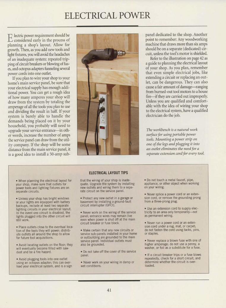
The workbench is a natural worksurface for using portable powertools. Mounting a power strip onone ofthe legs and plugging it intoan outlet eliminates the need for aseparate extension cord for every tool.
r When planning the electrical layout foryour shop, make sure that outlets forpower tools and lighting fixtures are onseDarate circuits.
o Unless your shop has bright windowsor your lights are equipped with batterybackups, include at least two separatelighting circuits in your electrical layout.In the event one circuit is disabled, thelights plugged into the other circuit wil lsti l l work.
r Place outlets close to the eventual loca-tion of the tools they wil l power; distrib-ute outlets all around the shoo to allowfor future tool acquisit ions.
. Avoid locating outlets on the floor; theywill eventually become fi l led with saw-dust and be a fire hazard.
. Avoid plugging tools into one outletusing an octopus adapter; this can over-load your electrical system, and is a sign
ETECTRICAT TAYOUT TIPS
that the wiring of your shop is inade-quate. Upgrade the system by installingnew outlets and wiring them to a sepa-rate circuit on the service panel.
o Protect any new outlet in a garage orbasement by install ing a ground-faultcircuit intenupter (GFCI).
. Never work on the wiring of the servicepanel; entrance wires may remain l iveeven when power is shut off at the maincircuit breaker or fuse block.
. Make certain that any new circuits orservice sub-panels installed in your homeor outbuilding are grounded to the mainservice panel. Individual outlets mustalso be grounded.
. Do not take off the cover of the serviceoane l .
o Never work on your wiring in damp orwet conditions.
. Do not touch a metal faucet, pipe,appliance, or other object when workingon your wiring.
. Never splice a power cord or an exten-sion cord, or remove the grounding prongfrom a three-prong plug.
. Use an extension cord to supply elec-tricity to an area only temporarily-notas permanenl wrnng.
. Never run a oower cord or an exten-sion cord under a rug, mat, or carpet;do not fasten the cord using tacks, pins,or staples.
. Never replace a blown fuse with one ofhigher amperage; do not use a penny, awasher, or foil as a substitute for a fuse.
o lf a circuit breaker trips or a fuse blowsrepeatedly, check for a short circuit, anddetermine whether the circuit is over-loaded.
4 I
SHOP LAYOUT
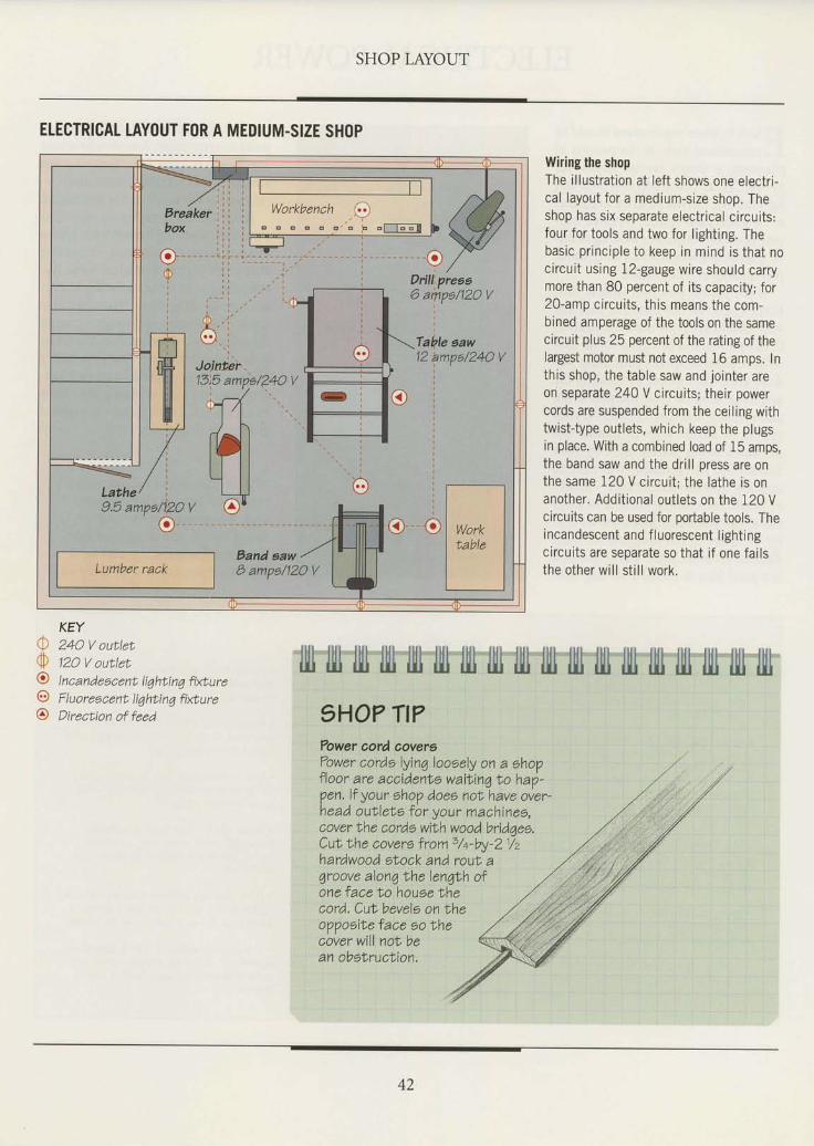
ETECTRICAT TAYOUT FOR A MEDIUM.SIZE SH(IP
24O V outlet12O V outletI n ca nd eecent liqhti nq firtu reF I uo reacent I iqhti nq fixtu reDirection of feed
Wiring the shopThe illustration at left shows one electri-cal layout for a medium-size shop. Theshop has six separate electrical circuits:four for tools and two for lighting. Thebasic principle to keep in mind is that nocircuit using !2-gauge wire should carrymore than 80 percent of its capacity; for20-amp circuits, this means the com-bined amperage of the tools on the samecircuit plus 25 percent of the rating of thelargest motor must not exceed 16 amps. Inthis shop, the table saw and jointer areorf separate 240 V circuits; their powercords are suspended from the ceiling withtwist-type outlets, which keep the plugsin place, With a combined load of 15 amps,the band saw and the drill press are onthe same 120 V circuit; the lathe is onanother. Additional outlets on the 120 Vcircuits can be used for portable tools. Theincandescent and fluorescent lightingcircuits are separate so that if one failsthe other will stil l work.
rh\v0ot
o
KEY
42
LIGHTING
] f you find yourself cutting off line orI cannot properly examine a f in ishunless you take your work outside, thelighting in your workshop may need anupgrade. At best, a poorly lit shop willmerely bring on fatigue; at worst, it cancontribute to sloppy, imprecise work andto accidents.
Fluorescent lights are the most pop-ular type of workshop lighting fixture.They cast a relatively shadowless light,the tubes are long-lasting, and they use20 percent to 30 percent less electricitythan incandescent lights of the samebrightness. Many woodworkers find thattoo much fluorescent light can result infatigue and headaches, however, and pre-fer the warmth of incandescent andtungsten lights,
At a minimum, a shop bigger than120 scuare feet needs 2 watts of incan-descent light or 3/q, walt of fluorescentlight per square foot, As in the electri-cal layout illustrated on page 42, shoplights should be circuits separate from
your tools. Ideally, the light fixtures willbe divided between tvvo seDarate circuits.As a rule of thumb, do not exceed 1600watts on one 20-amp circuit. Also, dis-tribute lighting fixtures around the shop;mounting a single fixture in the middleof the ceiling will make it difficult to illu-minate the shadowy areas at the edgesofthe shoo.
If possible, make the most of naturalIight; there is no better substitute, espe-cially for hand-tool work and finishing.Trying to evaluate planing, sanding, andfinishing jobs under artificial light canbe frustrating. Both fluorescent andincandescent light tend to distort or dis-guise the surface texture of natural andfinished wood surfaces. Natural light,particularly from the north, has a soft,non-glare quality. If your shop has a win-dow that faces north, place your work-bench under it.
Keep in mind that upgrading thelighting in your shop need not entailpurchasing expensive fixtures and
rewiring the system. Simply painting aconcrete floor a light color or coveringthe ceiling with white tiles will allowthese surfaces to reflect light, rather thanabsorb it.
IllI illt llll fill III fill fill illl llll llll llll I]I1 llll llll llll llll llll llll1HO? Tt?
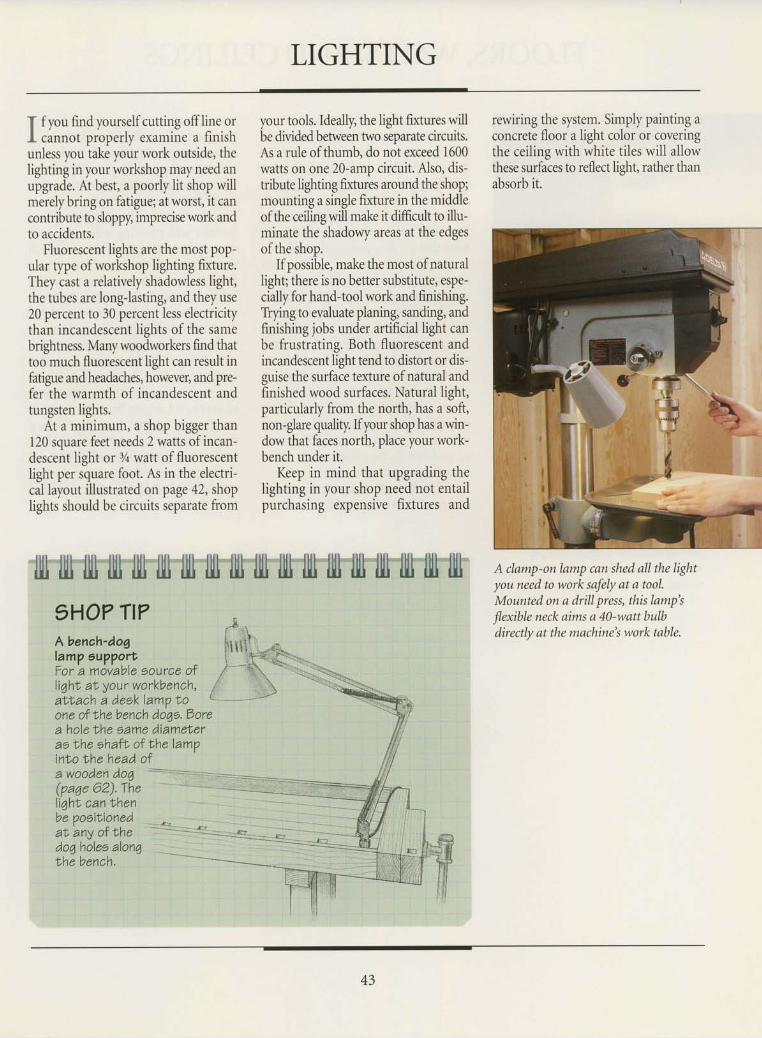
A clamp-on lamp can shed all the lightyou need to work safely at a tool.Mounted on a drill press, this lamp's
flexible neck aims a 4)-watt bulbdirectly at the machine's work table.
A benah'dog 1,, , , , \ ,lamo oupport l'lllt'+qil'\'-." l - - - A " . a \ rFor a movable source of , /
- - t \ - ' : - - : \l iqhl aI your workbench, / \
."r:r' i
a i tach A desklamp No {- ' - *--" ' " 'one of the bench doqe. Dorea hole Nhe eame diameNeras the ehafL of Lhe lampinto the head ofa w o o d en .d o,q +:==::::=--::R-::::-..--=.:
(pa4e62).The -- -------=:*:li,ahr, canLhen -:]b:e poeitioned *.al any of the - *-<<*.*t3- ja-. _;doqholeo alonq -__--the bench.
43
FLOORS, WALLS, AND CEILINGS
Q i":. most workshops are set up\,, In basements or garages, concretefloors are a common feature. Yet foranyone who has to spend much timestanding on concrete or sweeping itclean, the material can prove bothuncomfortable and inconvenient. Thehard surface is particularly tough ontools that are dropped accidentally.
Simply painting a concrete floor witha paint made specifically for the pulposewill keep down the dust and make thesurface easier to clean. Adhesive vinylfloor tile can be laid down as well. Yetmany woodworkers prefer the comfortof a raised wooden floor. A simole floorcan be constructed from sheeis of %-inch plyruood laid atop a grid of 1-by-2s on 12-inch centers. Not only is thisqpe of floor easier on the feet, but wiringfor stationary power tools can be rout-ed underneath the raised surface in %-inch olastic or steel conduit.
Unlike the walls of most homes, thoseofseparate workshops seldom are insu-
Iated. If you live in a northern climate,you can increase the thermal efficiencyof your shop by covering its walls withwood paneling or sheet material, andfilling the gap in between studs withinsulation. Wood paneling in particularcreates a warm, comfortable atmosphere.Interior wall covering will make yourshop quieter too, since the walls willabsorb some of the din of vour Dowertools. fu a bonus, you can conceal wiringbehind the walls. Make sure the base-ment walls do not leak before coveringthem with insulation and paneling.
To hide the exposed joists, ducts,and wiring above your head, considerinstalling a ceiling. A suspended tile ceil-ing, in which the tiles sit in a frameworkof supports hanging from the joists, isone popular option. In a large shop, adropped ceiling such as this will also helpretain heat. Acoustical ceiling tiles arean inexpensive alternative; the tiles areattached to furring strips that are nailedto the joists.Standing in one place for hours on
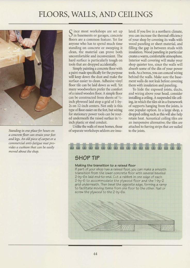
a concrete floor can strain your feetand legs. An old piece of carpet or acommercial anti-fatigue mat pro-vides a cushion that can be easilymoved about the shop.
lll1 ljll ilt fill lll1 llli llll firl ilu tlll llll tlll ilII llll llll lll1 fiu lllt9HO7 Tt?Making the transition to a raieed floorlf parl of your ehop hao a raised floor,you can make a smoolhlransilion from Nhe lower concrete floor with eeveral beveled2-by-6o laid end-No-end. Cut a rabbeN in one edqe of each2-W-6lo accommodate the plywood f loor and the 1-by-2qrid undernealh, Then bevel lhe oppoeite edqe, forminq a ram?lo f acilitate movinq it ems from one floor t o the oLher. Nail orscrew Ihe plywoodto the 2-by-Oe.
\ *ri.
44
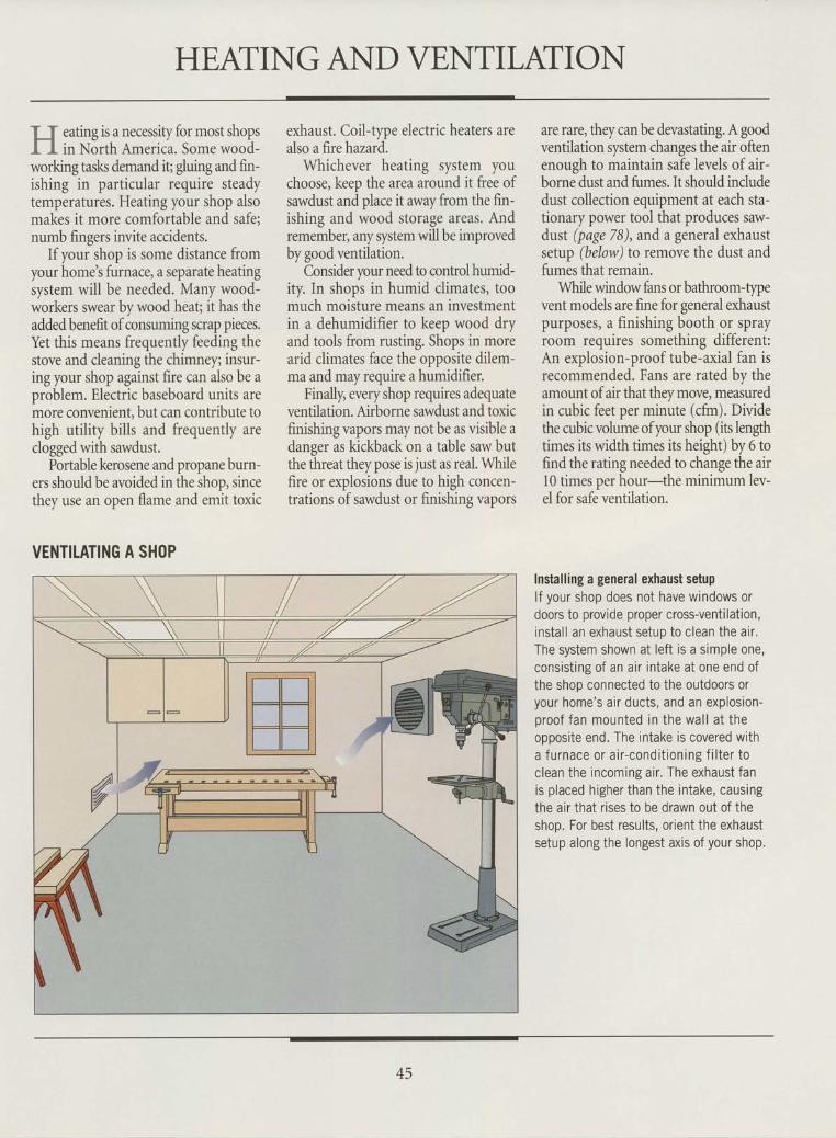
HEATING AND VENTILATI ON
ff eating is a necessiry for most shopsI I in North America. Some wood-working tasks demand it; gluing and fin-ishing in particular require steadytemperatures. Heating your shop alsomakes it more comfortable and safe;numb fingers invite accidents.
If your shop is some distance fromyour home's furnace, a separate heatingsystem will be needed. Many wood-workers swear by wood heaq it has theadded benefit of consuming scrap pieces.Yet this means frequently feeding thestove and cleaning the chimney; insur-ing your shop against fire can also be aoroblem. Electric baseboard units aremore convenient, but can contribute tohigh utility bills and frequently areclogged with sawdust.
Portable kerosene and propane burn-ers should be avoided in the shop, sincethev use an oDen flame and emit toxic
exhaust. Coil-type electric heaters arealso a fire hazard.
Whichever heating system youchoose, keep the area around it free ofsawdust and place it away from the fin-ishing and wood storage areas. Andremember, any system will be improvedby good ventilation.
Consider your need to control humid-ity. In shops in humid climates, toomuch moisture means an investmentin a dehumidifier to keep wood dryand tools from rusting. Shops in morearid climates face the opposite dilem-ma and may require a humidifier.
Finally, every shop requires adequateventilation. Airborne sawdust and toxicfinishing vapors may not be as visible adanger as kickback on a table saw butthe threat they pose is just as real. Whilefire or explosions due to high concen-trations of sawdust or finishing vapors
are rare, they can be devastating. A goodventilation system changes the air oftenenough to maintain safe levels of air-borne dust and fumes. It should includedust collection equipment at each sta-tionary power tool that produces saw-dust (page 7B), and a general exhaustsetup (below) to remove the dust andfumes that remain.
While window fans or bathroom-tlpevent models are fine for general exhaustpurposes, a finishing booth or sprayroom requires something different:An explosion-proof tube-axial fan isrecommended. Fans are rated by theamount of air that they move, measuredin cubic feet per minute (cfm). Dividethe cubic volume ofyour shop (its lengthtimes its width times its height) by 6 tofind the rating needed to change the air10 times per hour-the minimum lev-el for safe ventilation.
VENTILATING A SHOPInstalling a general exhaust setuplf your shop does not have windows ordoors to provide proper cross-ventilation,instal l an exhaust setup to clean the air .The system shown at left is a simple one,consist ing of an air intake at one end ofthe shop connected to the outdoors oryour home's air ducts, and an explosion-proof fan mounted in the wal l at theoooosite end. The intake is covered witha f u rnace or a i r -cond i t ion ing f i l te r toclean the incoming air . The exhaust fanis placed higher than the intake, causingthe air that rises to be drawn out of theshop. For best results, orient the exhaustsetup along the longest axis of your shop.
45
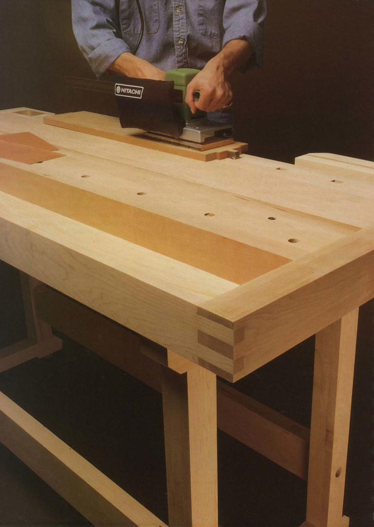
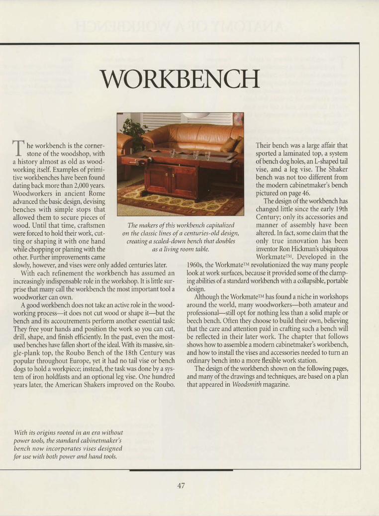
he workbench is the corner-stone of the woodshop, with
a history almost as old as wood-working itself. Examples of primi-tive workbenches have been founddating back more than 2,000 years.Woodworkers in ancient Romeadvanced the basic design, devisingbenches with simple stops thatallowed them to secure pieces ofwood. Until that time, craftsmenwere forced to hold their work, cut-ting or shaping it with one handwhile chopping or planing with theother. Further improvements came
i - j
I
r -L_ .
f -t _
WORKBENCH
The makers of this workbench capitalizedon the classic lines of a centuries-old design,
creating a scaled-down bench that doublesas a living room table.
slowly, however, and vises were only added centuries later.With each refinement the workbench has assumed an
increasingly indispensable role in the workshop. It is little sur-prise that many call the workbench the most important tool awoodworker can own.
A good workbench does not take an active role in the wood-working process-it does not cut wood or shape it-but thebench and its accoutrements perform another essential task:They free your hands and position the work so you can cut,drill, shape, and finish efficiently. In the past, even the most-used benches have fallen short of the ideal. With its massive, sin-gle-plank top, the Roubo Bench of the 18th Century waspopular throughout Europe, yet it had no tail vise or benchdogs to hold a workpiece; instead, the task was done by a sys-tem of iron holdfasts and an optional leg vise. One hundredyears later, the American Shakers improved on the Roubo.
Their bench was a large affair thatsported a laminated top, a systemofbench dogholes, an L-shapedtailvise, and a leg vise. The Shakerbench was not too different fromthe modern cabinetmaker's benchpictured on page 46.
The design ofthe workbench haschanged little since the early 19thCentury; only its accessories andmanner of assembly have beenaltered. In fact, some claim that theonly true innovation has beeninventor Ron Hickman's ubiquitousWorkmaterv. Developed in the
1960s, the Workmaterv revolutionized the way many peopleIook at work surfaces, because it provided some of the clamp-ing abilities of a sandard workbench with a collapsible, portabledesign.
Although the Workmaterru has found a niche in worlshopsaround the world, many woodworkers-both amateur andprofessional-still opt for nothing less than a solid maple orbeech bench. Often they choose to build their own, believingthat the care and attention paid in crafting such a bench willbe reflected in their later work. The chapter that followsshows how to assemble a modern cabinetmaker's workbench,and how to install the vises and accessories needed to turn anordinarybench into a more flexible work station.
The design of the workbench shown on the following pages,and many of the drawings and techniques, are based on a planthat appeared in Wo o dsmith magazine.
With its origins rooted in an era withoutpower tools, the standard cabinetmaker'sbench now incorporates vises designed
for use with both power and hand tools.
47
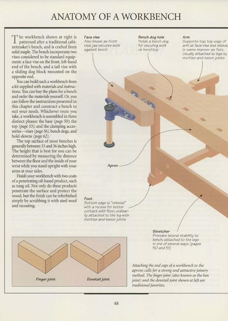
ANTATOMY OF AWORKBENCH
T h. workbench shown at right isI patterned after atraditional cabi-
netmaker's bench, and is crafted fromsolid maple. Thebendr incorporates twovises considered to be standard equip-ment a face vise on the front, left-handend of the bench, and a tail vise witha sliding dog block mounted on theopposite end.
You canbuildsuc,h aworkbench fromaht suppliedwith materials and instruc-tions. You canbuythe plans for abenchand order the materials yourself. Or, youcan followthe instructions presented inthis chapter and construct a bench tosuit your needs. Whichever route youtake, aworkbench is assembled in threedistinct phases: the base (page 50);thetop (page 53); andthe damping accessories-vises (page 56),benchdogs, andhold-downs (page62).
The top surface of most benches isgenerallybetriveen 33 and 36 incha high.The height that is best for you can bedetermined by measuring the distancebetween the floor and the inside ofyourwrist while you stand upright with yourarms at your sides.
Finish pur workbench with two coatsof a penetrating oil-basedproduct, suchas tung oil. Not only do these productspenetrate the surface and protect thewoo4 but the finish can be refurbishedsimply by scrubbing it with steel wooland recoating.
Faae vieeAlao known aa frontvioe; jaw aecures worka4ainot bench
Eottom ed6e ia "relieved"
with a recesa for betteraontact with floory ordinar-ily attached to the le4 withmortiae- and -tenon iointa
r-rl
f
Bench dog holeHolda a bench doqfor oecurinq workon benchtop
ArmSupporta top; top edqe ofarm atface-viae end relieved' Iin aame manner as feet.Uaually attached to le6a W - ,mortiae-and-tenon iointa - l
5tretcherFrovidea laf,eral atability tobench; attached to the leg6in one of aeveral wayo (paqea50 and 51)
Attaching the end caps of a worl&ench to theaprons calls for a strong and attradive joinerymethod The fingu joint (also known as the boxjoint) and the dovetail joint shown atw aretraditional favorita.
_l
l- t
-_l48
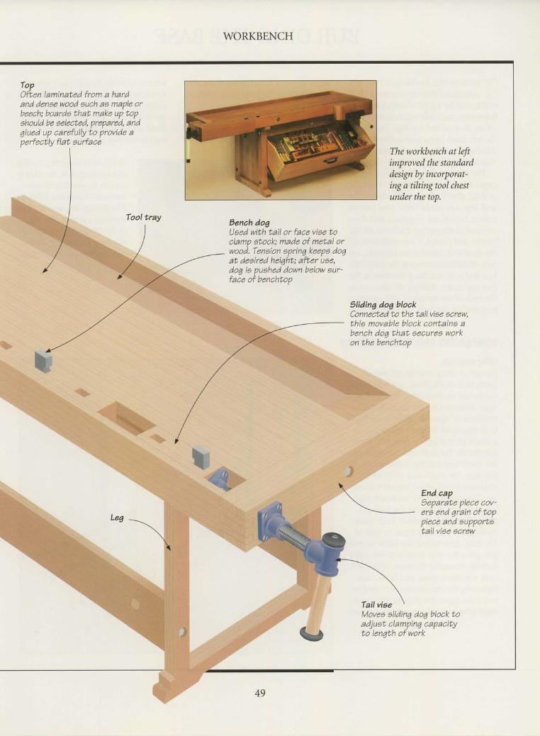
WORKBENCH
ToPOfLen laminal;ed from a hardand dense wood auch ae maple orbeech: boarda that make up topehould be aelected, prepared, and7lued up carefully to provtde ap e r-f e ctly fl at E u rf a c e
Tool tray
)
/ , ,
Aenah dogUaed with tarl or face vise toclamp eLock; made of metal orwood. Teneion oprinq keepa doqaL deeired heiqht; afLer uae,dog io puehed down below aur-face of benchtop
The workbench at leftimproved the standarddesign by incorporat-ing a tilting tool chestunder the top.
Sliding dog bloakConnecLed Lo Lhe tail viee ecrew,Lhts movable block contatna abench dog that. eecuree workon the benchtop
tes -\
End capL l e n a r a t e n i e r e r n t t -
era end grain of toppiece and eupportetatl vtse acrew
Movee elidin7 do1 block LoadjueL clamptn4 capaciLxto len7th of work
49
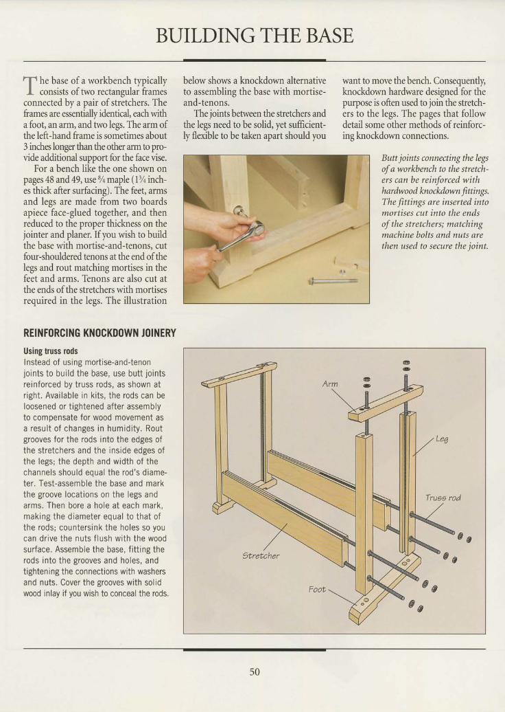
BUILDING THE BASE
"f h. base of a workbench typicallyJ- consists of two rectangular frames
connected by a pair ofstretchers. Theframes are essentially identical, each witha foot, an arm, and two legs. The arm ofthe left-hand frame is sometimes about3 inches longer than the other arm to pro-vide additional support for the face vise.
For a bench like the one shown onpages 48 and,49,use % maple (l% inch-es thick after surfacing). The feet, armsand legs are made from two boardsapiece face-glued together, and thenreduced to the proper thickness on thejointer and planer. If you wish to buildthe base with mortise-and-tenons, cutfour-shouldered tenons at the end ofthelegs and rout matching mortises in thefeet and arms. Tenons are also cut atthe ends of the stretchers with mortisesrequired in the legs. The illustration
REINF(|RCING KN(ICKD(IWN J(|INERY
Using truss rodsInstead of using mort ise-and-tenonjoints to bui ld the base, use butt jo intsreinforced by truss rods, as shown atr ight. Avai lable in ki ts, the rods can beloosened or t ightened after assemblyto compensate for wood movement asa resu l t o f changes in humid i ty . Routgrooves for the rods into the edges ofthe stretchers and the inside edges ofthe legs; the depth and width of thechanne ls shou ld eoua l the rod 's d iame-ter. Test-assemble the base and markthe groove locat ions on the legs andarms. Then bore a hole at each mark,mak ing the d iameter equa l to tha t o fthe rods; countersink the holes so youcan dr ive the nuts f lush with the woodsurface. Assemble the base, f i t t ing therods into the grooves and holes, andt ightening the connect ions with washersand nuts. Cover the grooves with sol idwood inlay if you wish to conceal the rods.
below shows a knockdown alternativeto assembling the base with mortise-and-tenons.
The joints betrveen the stretchers andthe legs need to be solid, yet sufficient-ly flexible to be taken apart should you
want to move the bench. Consequently,knockdown hardware designed for thepurpose is often used to join the stretch-ers to the legs. The pages that followdetail some other methods of reinforc-ine knockdown connections.
Bun joints connecting the legsof a workbench to the stretch-ers can be reinforced withhardwood knockdow n finings.The fittings are inserted intomortises cut into the endsof the stretchers; matchingmachine bolts and nuts arethen used to secure the ioint.
@ 8
50
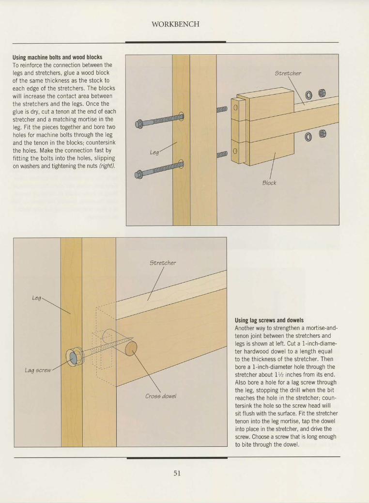
WORKBENCH
Using machine bolts and wood blocksTo reinforce the connection between thelegs and stretchers, glue a wood blockof the same thickness as the stock toeach edge of the stretchers. The blockswill increase the contact area betweenthe stretchers and the legs. Once theglue is dry, cut a tenon at the end of eachstretcher and a matching mortise in theleg. Fit the pieces together and bore twoholes for machine bolts through the legand the tenon in the blocks; countersinkthe holes. Make the connection fast byfitting the bolts into the holes, slippingon washers and tightening the nuts (right).
Using lag screws and dowelsAnother way to stren$hen a mortise-and-tenon joint between the stretchers andlegs is shown at left. Cut a 1-inch-diame-ter hardwood dowel to a length equalto the thickness of the stretcher. Thenbore a 1-inch-diameter hole through thestretcher aboullVz inches from its end.Also bore a hole for a lag screw throughthe leg, stopping the drill when the bitreaches the hole in the stretcher: coun-tersink the hole so the screw head willsit flush with the surface. Fit the stretchertenon into the leg mortise, tap the dowelinto place in the stretcher, and drive thescrew. Choose a screwthat is long enoughto bite through the dowe,.
5 1
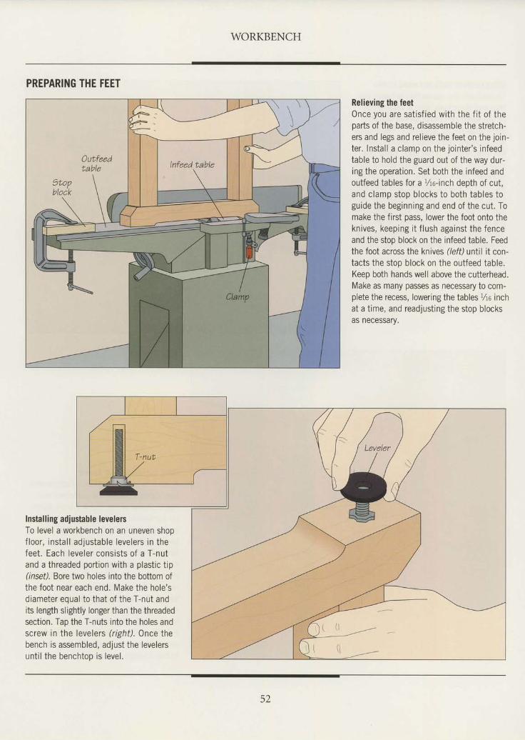
WORKBENCH
PREPARING THE FEET
Relieving the feetOnce you are sat isf ied with the f i t of theparts of the base, disassemble the stretch-ers and legs and relieve the feet on the join-ter. Install a clamp on the jointer's infeedtable to hold the guard out of the way dur-ing the operation. Set both the infeed andoutfeed tables for a %o-inch depth of cut,and clamp stop blocks to both tables toguide the beginning and end of the cut. Tomake the first pass, lower the foot onto theknives, keeping i t f lush against the fenceand the stop block on the infeed table. Feedthe foot across the knives (/efil until it con-tacts the stop block on the outfeed table.Keep both hands well above the cutterhead.Make as many passes as necessary to com-plete the recess, lowering the tables %o inchat a time, and readjusting the stop blocksas necessary.
Installing adjustable levelersTo level a workbench on an uneven shopf loor, instal l adjustable levelers in thefeet. Each leveler consists of a T-nutand a threaded portion with a plastic tip0nsel. Bore two holes into the bottom ofthe foot near each end. Make the hole'sdiameter eoual to that of the T-nut andits len$h slightly longer than the threadedsection. Tao the T-nuts into the holes andscrew in the levelers (right). Once thebench is assembled, adjust the levelersunt i l the benchtoo is level.
52
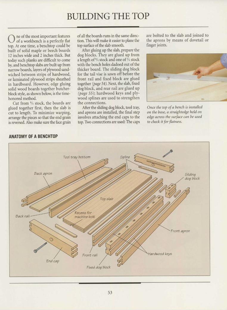
BUILDINGTHETOP
ne of the most important featuresof a workbench is a perfectly flat
top. At one time, a benchtop could bebuilt of solid maple or beech boards12 inches wide and 2 inches thick. Buttoday such planks are difficult to comeby, and benchtop slabs are built up fromnarrow boards, layers of ply,vood sand-wiched between strips of hardwood,or laminated plywood strips sheathedin hardboard. However, edge gluingsolid wood boards together butcher-blockstyle, as shownbelow is the time-honored method.
Cut from % stock, the boards areglued together first, then the slab iscut to length. To minimize warping,arrange the pieces so that the end grainis reversed. Also make sure the facegran
of all the boards runs in the same direc- are bolted to the slab and joined totion. This will make it easier to plane the the aprons by means of dovetail ortop surface of the slab smooth. finger joints.
After gluing up the slab, prepare thedog blocks. They are glued up froma length of% stock and one of% stockwith the bench holes dadoed out of thethicker board. The sliding dog blockfor the tail vise is sawn off before thefront rail and fixed block are gluedtogether (page 5a). Next, the slab, fixeddogblock, and rear rail are glued up(page 55); hardwood keys and ply-wood splines are used to strengthenthe connections.
After the sliding dog block, tool tray,and aprons are installed, the final stepinvolves attaching the end caps to thetop. Two connections are used: The caps
Once the top of a bench is installedon thebase, a straightedge held onedge across the surface can be usedto check it for Jlatness.
ANATOMY (lF A BENCHT(|P
9lidin4do7 block
Front rail
End cap
53
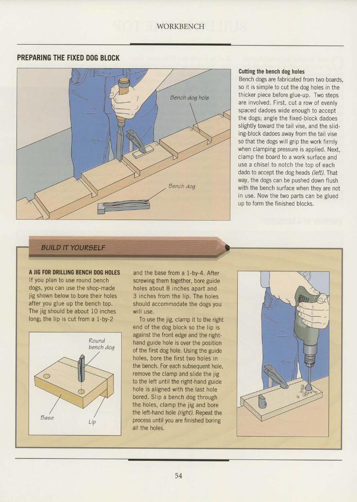
WORKBENCH
PREPARING THE FIXED D(|G BTOCK
Gutting the bench dog holesBench dogs are fabricated from two boards,so i t is s imple to cut the dog holes in thethicker piece before glue-up. Two stepsare involved. First , cut a row of evenlyspaced dadoes wide enough to acceptthe dogs; angle the f ixed-block dadoessl ight ly toward the tai l v ise, and the sl id-ing-block dadoes away from the tail viseso that the dogs will grip the work firmlywhen clamping pressure is appl ied. Next,clamp the board to a work surface anduse a chisel to notch the top of eachdado to accept the dog heads (lefl.fhatway, the dogs can be pushed down flushwith the bench surface when they are notin use. Now the two parts can be gluedup to form the f in ished blocks.
tsench doq hole
@tsenchdo4
A JIG FOR DRIttIl{G BENCH DOG HOTESlf you plan to use round benchdogs, you can use the shop-madejig shown below to bore their holesafter you glue up the bench top.The j ig should be about 10 incheslong; the lip is cut trom a l-by-2
Koundbench dog
and the base from a 1-by-4, Afterscrewing them together, bore guideho les about 8 inches apar t and3 inches from the l ip, The holesshould accommodate the dogs youwi l l use .
To use the jig, clamp it to the rightend of the dog block so the l ip isagainst the front edge and the right-hand guide hole is over the positionof the first dog hole. Using the guideholes, bore the f i rst two holes inthe bench. For each subsequent hole,remove the clamp and slide the jigto the left until the right-hand guidehole is al igned with the last holebored. Sl ip a bench dog throughthe holes, c lamp the j ig and borethe left-hand hole (right). Repeat theprocess until you are finished boringal l the holes,
54
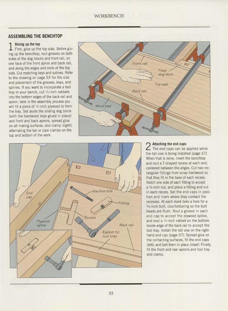
WORKBENCH
ASSEMBLING THE BENCHTOP' l Gluing up the topI First , glue up the top slab. Before glu-ing up the benchtop, rout grooves on bothsides of the dog blocks and front rai l , onone face of the front apron and back rai l ,and along the edges and ends of the topslab. Cut matching keys and spl ines. Referto the drawing on page 53 for the sizeand placement of the grooves, keys, andsplrnes. l f you want to incorporate a tooltray in your bench, cut r/z-inch rabbetsinto the bottom edges of the back rail andapron; later in the assembly process youwill f it a piece of r/z-inch plywood to formthe tray. Set aside the sl id ing dog block(with the hardwood keys glued in place)and front and back aprons, spread glueon all mating surfaces, and clamp (right),al ternat ing the bar or pipe clamps on thetoo and bottom of the work.
r) Attaching the end capsL m" end caps can be app l red wh i lethe tai l v ise is being instal led (page 57).When that is done, invert the benchtopand rout a T-shaped recess at each end,centered between the edges. Cut two rec-tangular f ittings from scrap hardwood sothat they fit in the base of each recess.Notch one side of each fitting to accepta 7e-inch nut, and place a f i t t ing and nutin each recess. Set the end caps in oosi-t ion and mark where they contact therecesses. At each mark bore a hole for a%- inch bo l t , counterbor ing so the bo l theads are f lush. Rout a groove in eachend cap to accept the p lywood sp l ine ,and rout a r/z-inch rabbet on the bottominside edge of the back rai l to accept thetool t ray. Instal l the tai l v ise on the r ight-hand end cap (page 5/). Spread glue onthe contact ing surfaces, f i t the end caps(\efl, and bolt them in place (inseil. Finally,f i t the front and rear aprons and tool t rayan0 c ramp.
55
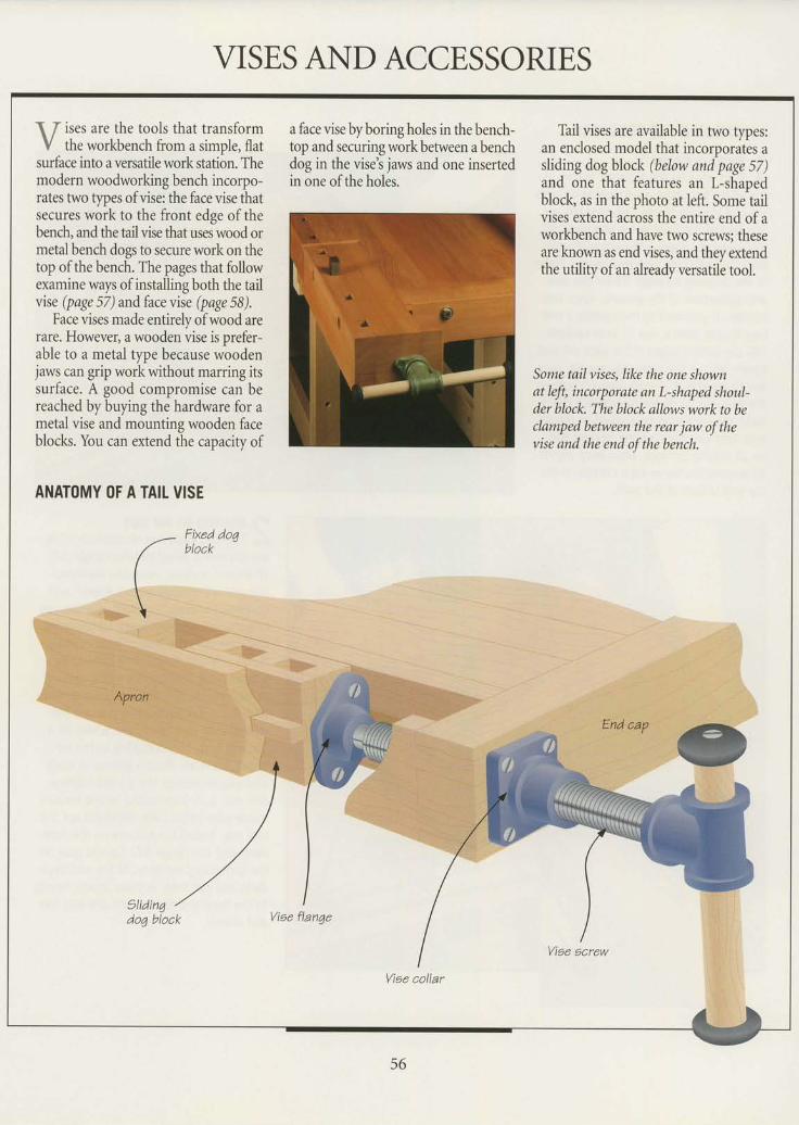
VISES AND ACCESSORIES
\ / ises are the tools that transformV the workbench from a simple, flat
surface into a versatile work station. Themodern woodworking bench incorpo-rates hvo tlpes of vise: the face vise thatsecures work to the front edge ofthebench, and the tail vise that uses wood ormetal bench dogs to secure work on thetop of the bench. The pages that followexamine ways of installing both the tailvise (page 57) and face vise (page 58).
Face vises made entirely of wood arerare. However, a wooden vise is prefer-able to a metal type because woodenjaws can grip work without marring itssurface. A good compromise can bereached by buying the hardware for ametal vise and mounting wooden faceblocks. You can extend the capacitv of
ANATOMY OF A TAII VISE
a face vise by boring holes in the bench-top and securing work between a benchdog in the vise's jaws and one insertedin one of the holes.
Thil vises are available in two types:an enclosed model that incorporates asliding dog block (below and page 57)and one that features an L-shapedblock, as in the photo at left. Some tailvises extend across the entire end ofaworkbench and have two screws; theseare known as end vises, and they extendthe utility ofan already versatile tool.
Some tail vises, like the one shownat left, incorporate an L-shaped shoul-der block. The block allows work to beclamped between the rear jaw of thevise and the end of the bench.
Fixed doqblock
Apron
Viee flanqe
Viae collar
56
-
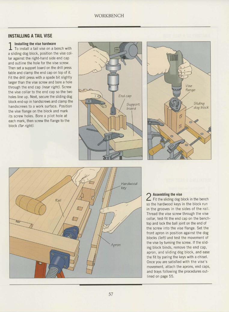
WORKBENCH
INSTALLING A TAIL VISE
1 Installing the vise hardwareI To ins ta l l a ta i l v ise on a bench w i tha sl id ing dog block, posi t ion the vise col-lar against the r ight-hand side end capand out l ine the hole for the vtse screw.Then set a support board on the drill presstable and clamp the end cap on top of i t .Fi t the dr i l l press with a spade bi t s l ight lylarger than the vise screw and bore a holethrough the end cap (near right), Screwthe vise col lar to the end cap so the twoholes l ine up. Next, secure the sl id ing dogblock end-up in handscrews and clamp thehandscrews to a work surface. Posit ionthe vise f lange on the block and marki ts sc rew ho les . Bore a p i lo t ho le a teach mark, then screw the f lange to theblock (far right).
r) Assembling the viseL f ttthe sliding dog block in the benchso the hardwood keys in the block runin the grooves in the s ides o f the ra i l .Thread the vise screw through the visecol lar, test- f i t the end cap on the bench-top and lock the bal l jo int on the end ofthe screw into the vise f lange. Set thefront apron in posit ion against the dogblocks (/eff) and test the movement ofthe vise by turning the screw. l f the sl id-ing b lock b inds , remove the end cap,apron, and s l id ing dog b lock , and easethe f i t by paring the keys with a chisel .Once you are sa t is f ied w i th the v ise 'smovement, at tach the aprons, end caps,and trays fol lowing the procedures out-l i n o d n n n e o p 5 5
57
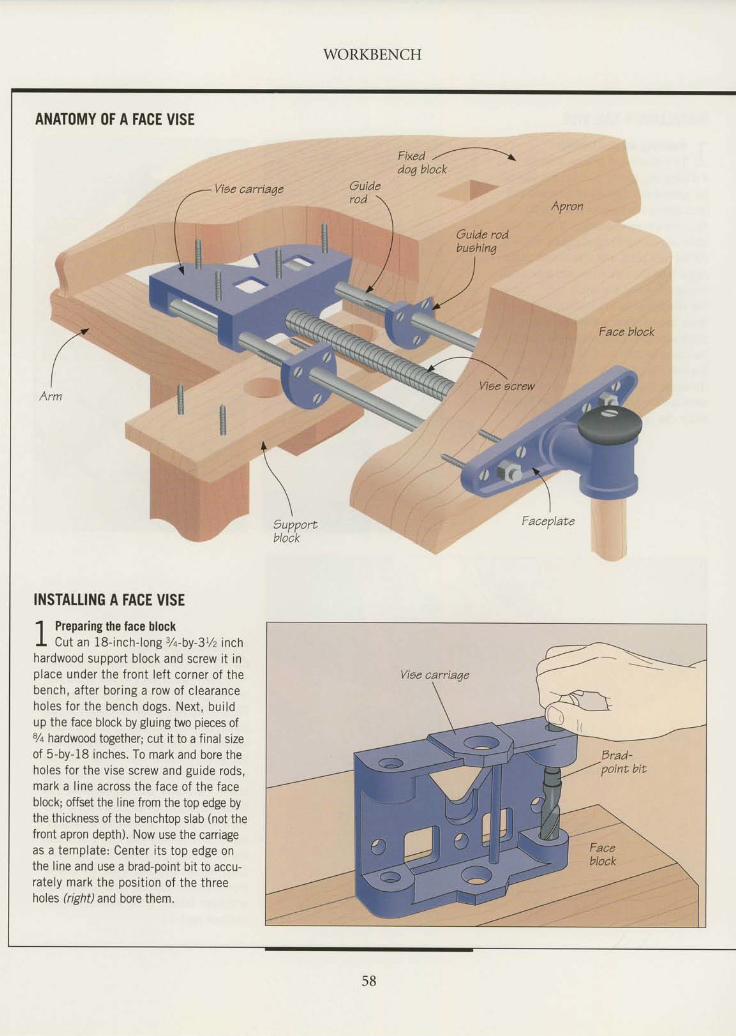
WORKBENCH
ANATOMY OF A FACE VISE
fixea ,,',------ldoq block
Apron
Faceplate
Face block
INSTALTING A FACE VISE
1 Preparing the face blockI Cut an 18-inch-long 3/a-by-31/z inchhardwood support block and screw i t inplace under the front lef t corner of thebench, after bor ing a row of c learanceho les fo r the bench dogs . Nex t , bu i ldup the face block by gluing two pieces of7a hardwood together; cut it to a final sizeof 5-by-18 inches. To mark and bore theholes for the vise screw and guide rods,mark a l ine across the face of the faceblock; offset the line from the top edge bythe thickness of the benchtop slab (not thefront apron depth). Now use the carriageas a template: Center i ts top edge onthe line and use a brad-point bit to accu-rately mark the posit ion of the threeholes (right) and bore them.
58
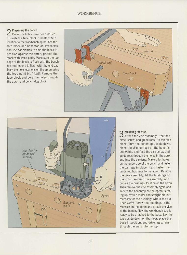
WORKBENCH
r) Preparing the benchL Once the holes have been dr i l ledthrough the face block, t ransfer thetrlocation to the workbench apron. Set theface block and benchtop on sawhorsesand use bar clamps to hold the block inposit ion against the apron; protect thestock with wood pads. Make sure the topedge of the block is f lush with the bench-top and i ts end is f lush with the end cap.Mark the hole locations on the apron usingthe brad-poinI bi I (r ight) . Remove theface b lock and bore the ho les th roughthe apron and bench dog block,
Mounting the viseAttach the vise assembly- the face-
plate, screw, and guide rods-to the faceb lock . Turn the benchtop ups ide down,p lace the v ise car r iage on the bench 'sunderside, and feed the vise screw andguide rods through the holes in the apronand into the carr iage. Make pi lot holeson the underside of the bench and fastenthe carr iage in place. Next, fasten theguide rod bushings to the apron: Removethe v ise assembly , f i t the bush ings onthe rods , remount the assembly , andoutline the bushings' location on the apron.Then remove the vise assembly again andsecure the benchtop so the apron is fac-ing up. With a router and straight bit, cutrecesses for the bushings within the out-lines (left). Screw the bushings to therecesses in the aoron and attach the viseto the bench. Now the workbench top isready to be attached to the base. Lay thetop upside down on the f loor, place thebase in posit ion, and dr ive lag screwsthrough the arms into the top.
59
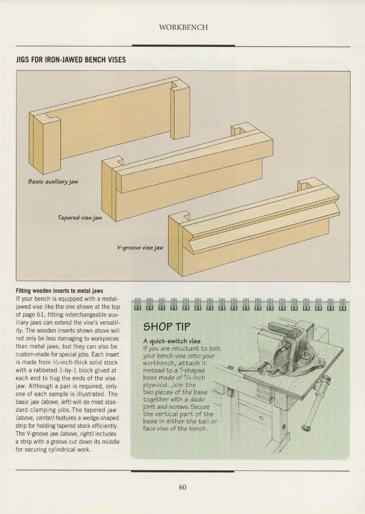
WORKBENCH
JIGS FOR IRON.JAWED BENCH VISES
Eaeia auxiliary jaw
Tapered vieejaw
V-groove viae jaw
Fitting wooden inserts to metal jawslf your bench is equipped with a metal-jawed vise l ike the one shown at the topof page 61, f i t t ing interchangeable aux-i l iary jaws can extend the vise's versat i l -ity. The wooden inserts shown above willnot only be less damaging to workpiecesthan metal jaws, but they can also becustom-made for special jobs. Each insertis made from r/z-inch-thick solid stockwith a rabbeted 1-by-1 block glued ateach end to hug the ends o f the v isejaw. A l though a pa i r i s requ i red , on lyone o f each sample is i l l us t ra ted . Thebasic jaw (above, left)will do most stan-dard c lamping jobs .The tapered jaw(above, center) features a wedge-shapedstrip for holding tapered stock efficiently.The V-groove jaw (above, rghf) includesa strip wrth a groove cut down its middlefor securing cyl indr ical work.
plywood. Join Ihe \
fill fill lll} tlll fill fill llll tlll ill} Illt llll llit llll tlll fill tlll illl ltll5HO? TI?A quiak-owitahviself you are reluclanlto bollyour bench vioe onlo yourworkbench, at lach i tineheadto aT-shaoedbase made of 5/+-inch
twopieceeofthebase \to7ether with a dadoioint and 5crew6. 5 ecureLhe verlical parl of Nhebase in e iNher Lhe t a i l o rface viee of the bench.
60
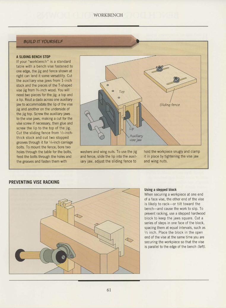
WORKBENCH
A SLIDING BENCH STOPlf your "workbench" is a standardtable with a bench vise fastened toone edge, the jig and fence shown atright can lend it some versatility. Cutthe aux i l ia ry v ise jaws f rom f - inch
stock and the pieces of the T-shapedvise jig from %-inch wood. You willneed two pieces for the jig: a top anda lip. Rout a dado across one auxiliaryjaw to accommodate the lip of the visejig and another on the underside ofthe jig top. Screw the auxiliary jawsto the vise jaws, making a cut for thevise screw if necessary, then glue andscrew the l ip to the top of the j ig.Cut the sl id ing fence from r/z- inch-
thick stock and cut two stoppedgrooves through it for Yq-inch carriagebolts. To mount the fence, bore twoholes through the table for the bolts,feed the bolts through the holes andthe grooves and fasten them with
washers and wing nuts. To use the jigand fence, sl ide the l ip into the auxi l -iary jaw, adjust the sl id ing fence to
hold the workpiece snugly and clampit in place by tightening the vise jawand w ing nu ts .
Auxiliaryviae jaw
PREVENTING VISE RACKING
Using a stepped blockWhen securing a workpiece at one endof a face vise, the other end of the viseis l i ke ly to rack-or t i l t toward thebench-and cause the work to sl ip. Toprevent racking, use a stepped hardwoodb lock to keep the jaws square . Cut aseries of steps in one face of the block,spacing them at equal intervals, such asr/z inch. Place the block in the openend of the vise at the same time you aresecuring the workpiece so that the viseis parallel to the edge of the bench (/eft).
6 l
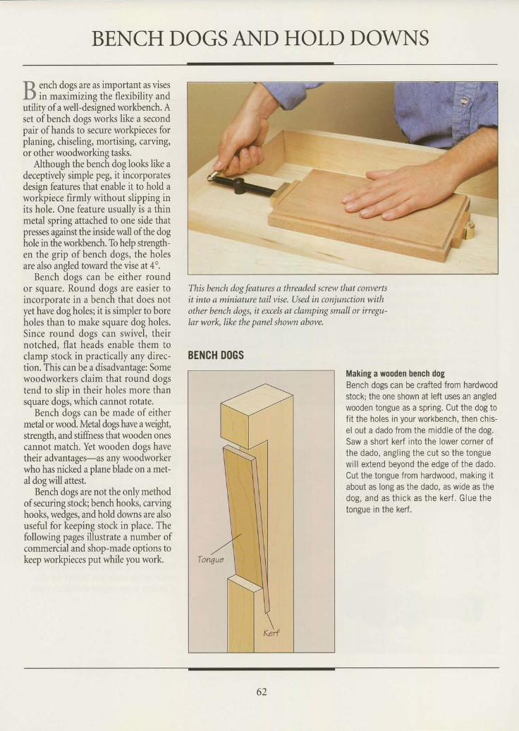
BENCH DOGSAND HOLD DOVNS
p ench dogs are as important as visesLl in maximizing the flexibility andutility of a well-designed workbench. Aset of bench dogs works like a secondpair of hands to secure workpieces forplaning, chiseling, mortising, carving,or other woodworking tasks.
Although the bench dog looks like adeceptively simple peg, it incorporatesdesign features that enable it to hold aworkpiece firmly without slipping inits hole. One feature usually is a thinmetal spring attached to one side thatpresses against the inside wall of the doghole in the workbench. To help strength-en the grip of bench dogs, the holesare also angled toward the vise at 4o.
Bench dogs can be either roundor square. Round dogs are easier toincoroorate in a bench that does notyet hJve dog holes; it is simpler to boreholes than to make square dog holes.Since round dogs can swivel, theirnotched, flat heads enable them toclamp stock in practically any direc-tion. This can be a disadvantage: Somewoodworkers claim that round dogstend to slio in their holes more thansquare dogi, which cannot rotate.
Bench dogs can be made of eithermetal or wood. Metal dogs have a weight,strength, and stiffiress that wooden onescannot match. Yet wooden dogs havetheir advantages-as any woodworkerwho has nicked a plane blade on a met-al dog will attest.
Bench dogs are not the only methodofsecuring stock; bench hooks, carvinghooks, wedges, and hold downs are alsouseful for keeping stock in place. Thefollowing pages illustrate a number ofcommercial and shop-made options tokeep workpieces put while you work.
This bench dog features a threaded screw that convertsit into a miniature tail vise. Used in conjunction withother bench dogs, it excek at clamping small or irregu-lar work, like the panel shown above.
BENCH DOGS
Making a wooden bench dogBench dogs can be crafted from hardwoodstock; the one shown at left uses an angledwooden tongue as a spring. Cut the dog tof i t the holes in your workbench, then chis-el out a dado from the middle of the dog.Saw a short kerf into the lower corner ofthe dado, angl ing the cut so the tonguewil l extend beyond the edge of the dado,Cut the tongue from hardwood, making itabout as long as the dado, as wide as thedog, and as th ick as the ker f . G lue thetongue in the kerf.
62
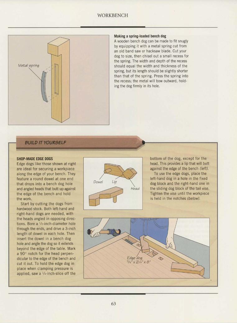
WORKBENCH
Making a spring-loaded bench dogA wooden bench dog can be made to fit snuglyby equipping i t with a metal spr ing cut f roman old band saw or hacksaw blade. Cut yourdog to size, then chisel out a smal l recess forthe spring. The width and depth of the recessshould eoual the width and thickness of thespring, but its length should be slightly shorterthan that of the spr ing. Press the spr ing intothe recess; the metal will bow outward, hold-ing the dog f i rmly in i ts hole.
SHOP-MADE EDGE DOGSEdge dogs like those shown at rightare ideal for securing a workpiecealong the edge of your bench. Theyfeature a round dowel at one endthat drops into a bench dog holeand angled heads that butt up againstthe edge of the bench and holdthe work.
Start by cutting the dogs fromhardwood stock. Both left-hand andright-hand dogs are needed, withthe heads angled in opposing direc-tions. Bore a t/z-inch-diameter holethrough the ends, and drive a 3-inchlength of dowel in each hole. Theninsert the dowel in a bench doghole and angle the dog so it extendsbeyond the edge of the table. Marka 90' notch for the head perpen-dicular to the edge of the bench andcut i t out. To hold the edge dog inp lace when c lamping pressure isappl ied, saw a %-inch-sl ice off the
bottom of the dog, except for thehead. This provides a lip that will buttagainst the edge of the bench (/eff).
To use the edge dogs, place theleft-hand dog in a hole in the f ixeddog block and the r ight-hand one inthe sl id ing dog block of the tai l v ise.Tighten the vise until the workpieceis held in the notches (below).
3/+"x21/+"x8"
63
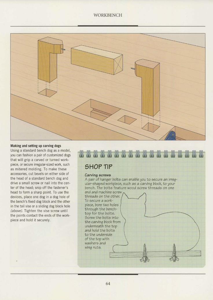
WORKBENCH
Making and setting up carving dogsUsing a standard bench dog as a model,you can fashion a pair of customized dogsthat will grip a carved or turned work-piece, or secure irregular-sized work, suchas mitered molding. To make theseaccessories, cut bevels on either side ofthe head of a standard bench dog anddrive a small screw or nail into the cen-ter of the head; snip off the fastener'shead to form a sharp point. To use thedevices, place one dog in a dog hole ofthe bench's fixed dog block and the otherin the tail vise or a sliding dog block hole(above). Tighten the vise screw untilthe points contact the ends of the work-piece and hold it securely.
64
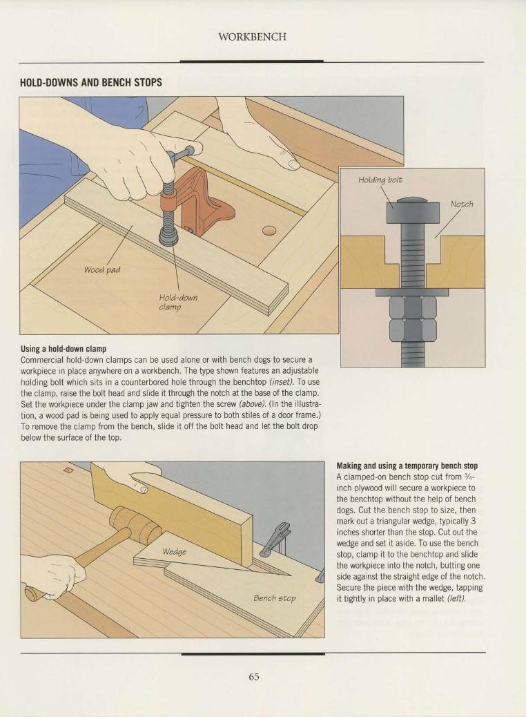
WORKBENCH
HOLD-DOWNS AND BENCH STOPS
Using a hold-down clampCommercial hold-down clamps can be used alone or with bench dogs to secure aworkpiece in place anywhere on a workbench. The type shown features an adjustableholding bolt which sits in a counterbored hole through the benchtop (insef). To usethe clamp, raise the bolt head and slide it through the notch at the base of the clamp.Set theworkp ieceunder thec lamp jawandt igh ten thescrew (above) . ( ln the i l lus t ra -tion, a wood pad is being used to apply equal pressure to both siiles of a door frame.)To remove the clamp from the bench, slide it off the bolt head and let the bolt dropbelow the surface of the top.
Making and using a temporary bench stopA clamped-on bench stop cut from 7a-inch plywood will secure a workpiece tothe benchtop without the help of benchdogs. Cut the bench stop to size, thenmark out a tr iangular wedge, typical ly 3inches shorter than the stoo. Cut out thewedge and set it aside. To use the benchstop, clamp i t to the benchtop and sl idethe workpiece into the notch, butting oneside against the straight edge of the noich.Secure the piece with the wedge, tappingit tightly in place with a mallet (/eff).
65
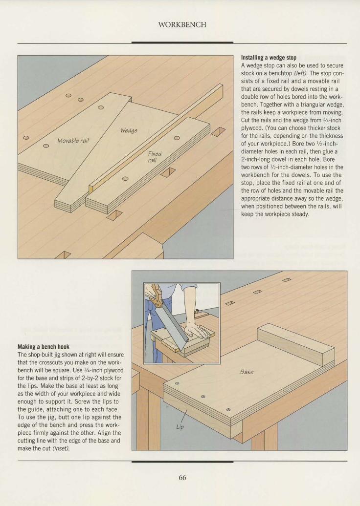
WORKBENCH
Installing a wedge stopA wedge stop can also be used to securestock on a benchtop (left).The stop con-sists of a fixed rail and a movable railthat are secured by dowels resting in adouble row of holes bored into the work-bench. Together with a triangular wedge,the rails keep a workpiece from moving.Cut the rails and the wedge from %-inchplywood. (You can choose thicker stockfor the rails, depending on the thicknessof your workpiece.) Bore two L/z-inch-
diameter holes in each rail, then glue a2-inch-long dowel in each hole. Boretwo rows of %-inch-diameter holes in theworkbench for the dowels. To use thestop, place the fixed rail at one end ofthe row of holes and the movable rail theappropriate distance away so the wedge,when positioned between the rails, willkeep the workpiece steady.
Making a bench hookThe shop-built jig shown at right will ensurethat the crosscuts you make on the work-bench will be square. Use 3/a-inch plywoodfor the base and strips of 2-by-2 stock forthe lips. Make the base at least as longas the width of your workpiece and wideenough to support it. Screw the lips tothe guide, at taching one to each face.To use the j ig, butt one l ip against theedge of the bench and press the work-piece firmly against the other. Align thecutting line with the edge of the base andmake the cut (inset).
66
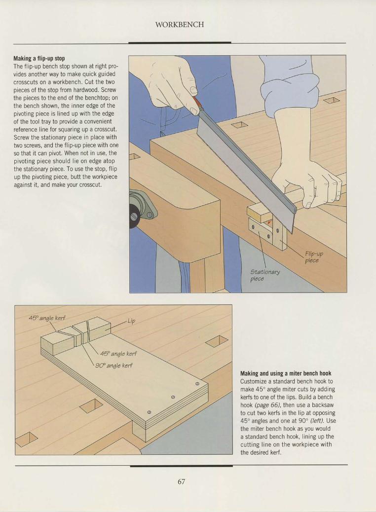
WORKBENCH
Making a flip-up stopThe flip-up bench stop shown at right pro-vides another way to make quick guidedcrosscuts on a workbench. Cut the twopieces of the stop from hardwood. Screwthe pieces to the end of the benchtop; onthe bench shown, the inner edge of thepivot ing piece is l ined up with the edgeof the tool tray to provide a convenientreference line for squaring up a crosscut.Screw the stat ionary piece in place withtwo screws, and the flip-up piece with oneso that it can pivot. When not in use, thepivot ing piece should l ie on edge atopthe stationary piece. To use the stop, flipup the pivoting piece, butt the workpieceagainst it, and make your crosscut.
Making and using a miter bench hookCustomize a standard bench hook tomake 45" angle miter cuts by addrngkerfs to one of the lios. Build a benchhook (page 66), then use a backsawto cut two kerfs in the lip at opposing45'angles and one at 90" (/eff). Usethe miter bench hook as you woulda standard bench hook, l in ing up thecut t ing l ine on the workp iece w i ththe desired kerf.
67
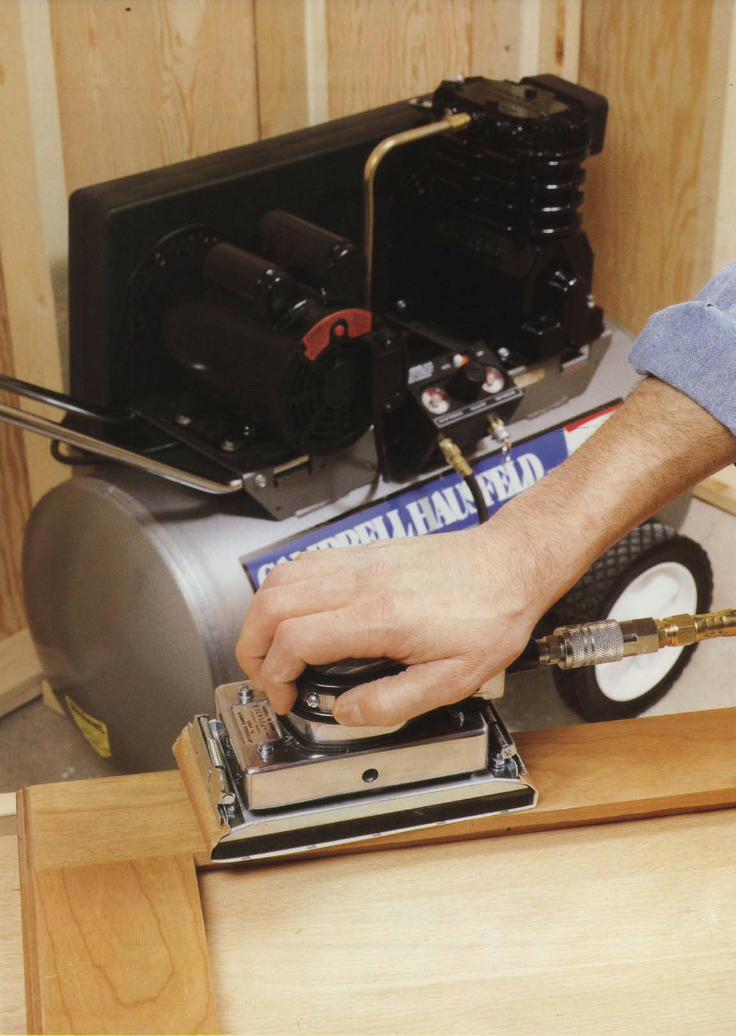
* \ .
t { : r
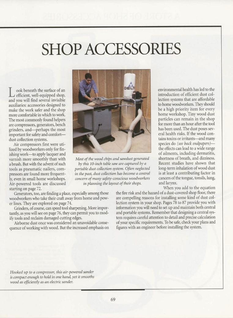
SHOPACCE,SSOruES
ii-r- r:ne3'jr ,-n3 :,jrl?tt I'l 'ill
- I L!!uur-'r''Lrrlq rrLdur rr@ rLu Lv urL
, . : , j : , - ! 1 ' : ] : . - , - : . - . : : : r . : : = : : : : - G f - - - = - - _ o * = . * . ' . - , ' j - - . - : , . : , -
,,,#f,i1,ffiil:,H1,,yffi ;:i lWw'jffi ;ilH:.t.:i:,::ii::?,#,:,G
and you will find severi
make the work safer an
important for safety and
varniih *ore smoothly thin with Most of the wood chips and sawdust generated shortness of breath, and dizziness.abrush.Butwiththeadventofsuch bythisl0-inchtablesawarecapturedbya Recent studies have shown thattools as pneumatic nailers, com- portable dust collection system. Ofien neglected long-term inhalation ofwood dustpr.rrotr ir. found more frequent- in the past, dust collection has become a central is at least a contributing factor iniy, .u.n in small home workshops. tort"i, of many safety-conscious woodworkers cancers of the tongue, tonsils' lung,Air-powered tools are discussid in planningthelayout of their shops. *9 b.fnt'starting onpage72. When you ad{ 1o the equation
Geniratorsltoo, are finding a place, especially among those the fire risk and the hazard of a dust-covered.lhop floor, therewoodworkers who take their irait away from home and pow- are compelling reasons for installing some kind of dust col-er lines. They are explored onpageTl'.
- lection system in yo_ur shop. Pages 78 to 87. provide you with
Grinders, of course, can speed tool sharpening. More impor- information you will need to set up_ and-maintain both centraltantly, as you will see on page 76, they canpermit you to mod- and portable systems. Remember.that designing a central sys-ifi'tools and reclaim dariraged cutting edges. temrequires carefrrlattentionlo {etail an{Precise calculation'
Airborne dust once wasionsidered an unavoidable conse- ofyour specific requirements. To be safe, checkyour plans andquence ofworking with wood. But the increased emphasis on figures with an engineer before installing the system.
ishingwork-to applylacquer and -72:i*.ii;*''{ r"-rqrffi
of ailments, inclt'ding dermatitis,
Hooked up to a compressor, this air-powered sanderis compact enough n hold in one hand. yet it smoothswood as fficiently as an electric sander.
69
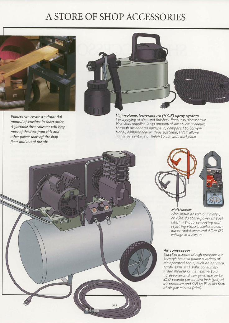
A STORE OF SHOP ACCESSORIES
High-volume, Iow-preaeure (HVLP) epray syltemPlaners can create a substantialmound of sawdust in short order.A portable dust collector will keepmost of the dust from this andother power tools offthe shopJloor and out of the air.
For applying ataina and finishee. FeaLuree electric tur-bine that auppliea larae amount of air at low nreaartreouppliea lar4e amount of air at low preaeure
ir hoge to aprav aun: comoared lio conven-throuqh air hoae to epray 7un; compared to ionven-tional, compressed-air type eyateme, HVLF allowational, compressed-air type eyateme, HVLF allowahiqher percenta1e of fi niah to contact workpiece
MultitesterAleo known aa volt-ohmmeter,or VOM. tsatte ry- p owe red to oluaed in troubleahootina andrepairing electric deviceZ: mea-eures reeiatance and AC or DCvoltaqe in a circuit
Air compreaoorSuppliea atream of high preeeure airthrouqh hoae to power a variety ofair-operated toola, auch aa aandere,epray qune, and drilla; coneumer-4rade modele ranqe froml/a to 5nor9ePower and can qenerate uP to2OO pounda p€r oquare inch (pei) ofair preeaure and O.3 to 15 cubic feetof air per minute (cfm).
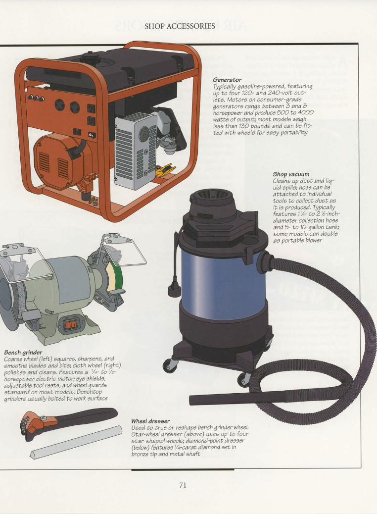
SHOP ACCESSORIES
GeneratorTypic ally g a a oli n e' powered, featu ri n quo to four 12O- and 24O-volt out-leta. Motors on congumer'qradeqeneratoro ranqe batween 3 and Bhoraapower and produce 5OO to 4OOOwatto of output; moet modela weiqhleaathanlSO poundo and can befit-ted with wheela for eaay portabili$
thop vacuumCleana up duat and liq-uid apills; hoae can beattached to individualtools to collect duat asit ia produced. Typicallyfeaturea 1%- to 2%-inch'diameter collection hoaeand 5- to 1O'qallon tank;some modele can doubleaa portable blower
Bench grlnderCoarse wheel (left) 6quarea, aharpena, andamootha bladea and bits; cloth wheel (ri4ht)poliahea and cleana. Features a 1/+- tol/z''horoepower
electric moton eye ahielda,adjueiable tool resta, and wheel 1uardaatandard on most modela, Benchtopgrindero ueually bolted to work aurface
Wheel dreeeerUsed to true or reehapa bench 4rinderwheel.gtar-wheel dresaer (above) ueea uP to fourota r- ohaped wheela; diamond-point dreaser(below) fiatureal/+'carat diamond aet inbronze tip and metal shaft
7T

AIR COMPRESSORS
A n air compressor can be fitted withA a larse number of tools and attach-ments, riaking it a convenient shopaccessory. In some shops, a compressorcan represent an alternative to someelectric tools. For others, it can be a valu-able supplement.
Air-powered tools work best at aspecific pressure indicated in theowner's manual for the particulartool. Before starting a job, the com-pressor's air regulator should beadjusted to the proper settingforthe task at hand.
Pneumatic drills, grinders, sanders,and wrenches perform at least as effec-tively as their ilectric-powered coun-terparts. Some tools, like sprayers,nailers, and abrasive cleaners, are clear-ly superior to the alternatives.
Compressors and the tools theydrive are inherently simple: The air isdrawn in, pressurized by a diaphragmor one or more pistons, and usuallystored in a tank. When the trigger on anair-driven tool is pressed, the air travelsthrough a hose to power the tool.
Because they contain no heavy elec-tric motor, most air tools are lighter,cheaper, and easier to repair than theircousins. They cannot overheat, and thereis no danger ofelectrical shock.
Compressed-air power does havesome drawbacks, chiefly the cost of thecompressor itself and maintenance. Airdrills and the like must be oiled daily.And you will invest several hundred dol-lars in a compressor that is capable ofdriving typical shop tools.
Some air-powered tools require a siz-able volume of air, usually measured incubic feet per minute (cfm); others needa minimum level of air pressure inpounds per square inch (psi). Whenchoosing a compressor, consider the cfrnor psi requirements of the air-poweredtools you plan to use and buy a com-pressor with slightly more power. Younever know when you will want toexpand your tool inventory.
AIR-POWERED TOOTS AND ACCESSORIES
Jitterbug sander)rbital eander capable of pro-ducina 25OO atrokes oerminute: weigho leas than 5pounda. Keauirea 6.5 cfm at'9O
pai; muat be uaed withtank- mounted compreeaorwith at leaat 3 horaepower
3/a-inch drill that turna bitaat 25OO rpm; wei4he only2 % pounde. Kequirea 5cfm at 90 pei; muet beueed with tank-mountedcompresoor with at leaat'l horeepower
Drill
9pray gunHeavy-duty aprayer withadjuatable fluid and aircontrole. Kequiree 5.5 cfmat 40 pai; can be uaed withany compreoaor with morethan t horeepower
72
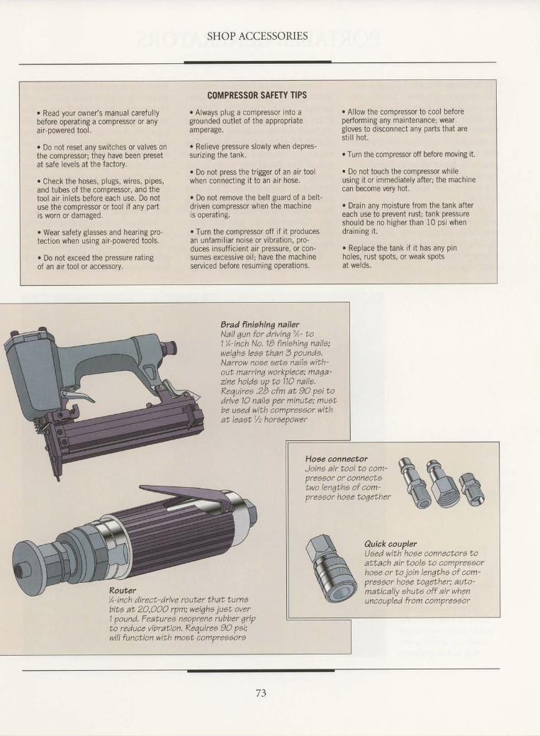
SHOP ACCESSORIES
o Read your owner's manual carefullybefore operating a compressor or anyair-powered tool.
r Do not reset any switches or valves onthe compressor; they have been presetat safe levels at the factory.
. Check the hoses, plugs, wires, pipes,and tubes of the compressor, and thetool air inlets before each use. Do notuse the compressor or tool if any partis worn or damaged.
o Wear safety glasses and hearing pro-tection when using air-powered tools.
. Do not exceed the pressure ratingof an air tool or accessory.
C(|MPRESSOR SAFETY TIPS
. Always plug a compressor into agrounded outlet of the appropriateamperage.
r Relieve pressure slowly when depres-surizing the tank.
o Do not press the trigger of an air toolwhen connecting it to an air hose.
r Do not remove the belt guard of a belt-driven comoressor when the machineis operating.
. Turn the compressor off if it producesan unfamiliar noise or vibration, pro-duces insufficient air pressure, or con-sumes excessive oil; have the machineserviced before resuming operations.
. Allow the compressor to cool beforeperforming any maintenance; weargloves to disconnect any parts that aresti l l hot.
r Turn the compressor off before moving it.
o Do not touch the compressor whileusing it or immediately after; the machinecan become very hot.
r Drain any moisture lrom the tank aftereach use to prevent rust; tank pressureshould be no higher than 10 psi whendraining it.
. Replace the tank if i t has any pinholes, rust spots, or weak spotsat welds.
Brad ffniahing nailerNail qun for drivinq 3/u- to1%-inch No.1B finishin7 naila:wei1ha leas than 3 pounda.Narrow nose eets naile with'out. marrinq workpiece: ma4a-zine holds up to 11O naila.Requireo .2b cfm at 90 paitodrive 10 naile per minute; muetbe used with compreaaor withat leaetl/z horaepower
Router%-inch direct-drive router that turnsbits at 2O,OOO rpm; wei1ha juat over1 pound. Featuree neoprene rubber qripto reduce vibration, Requiree 90 poi;will function with most compreoaore
j:i,2";:#:fi;"",. ww
Presgor Or Connect?two len4tha of com'preeeor hooe toqether
Quiak couplerUaed with hoae connectora toattach air tools to compreeeorhose or to join lenqtha of com-preooor hoee toqether; auto'matically ahuta off air whenuncoupled from compreeeor
73

PORTABLE GENERATORS
,| he average home and shop is so wellI equippedwith electric fixtures, out-
lets, and extension cords that it is easyto take for granted the essential role thatelectricity plays in our lives. Yet a pow-er outage can quickly remind you ofthat role. At such a time, a portable ACgenerator becomes an indispensableaccessory for your home, your shop, orin a remote cabin where power lines donot reach.
AC, or alternating current) genera-tors typically feature a gasoline motorthat drives an alternator. Models areavailablewith motors ranging from 3 to8 horsepower, producing 500 to 4000watts of power.
There are several factors to considerwhen selecting a generator, and the charton page 75 can help gurde you. The gen-erator must produce enough power tostart and run the tools and any otherelectrical devices you plug into it. Thewattage ratings listed on the chart aretypical. You should refer to the actualrating of your tool, which is usuallyprinted on the tool body. Ifnot, youcan calculate the rating by multiplyingthe tool's amperage rating by the volt-age. (For example, a 3-amp tool oper-ating on 120 volts would have a wattagerating of 360.)
The wattage rating of a generatorrefers to its continuous runningwattage.
Although all models feature a surge ormaximum rating as much as 25 percenthigher than the running value, youshould rely on the running wattage rat-ing when choosing a generator. A gen-erator with more power than you needwill run more smoothly for longerstretches and require less maintenance.
Most generators are equipped withone to four 120-volt outlets. Many mod-els also have a 240-volt outlet anda12-volt DC output for charging batteries.
Make sure that anygeneratoryoubuyis equipped with an effective muffler.Also check the size of the fuel tank. Thegenerator should be able to run for atleast 90 minutes on a frrll tank.
Portable generators area handy source of elec-
tricity during power out-ages or in locations where
a conventional electricalsupply is unavailable.
Rated at 3500 watts, thismodel is able to drive vir-tually any electric work-
shop tool or appliance.
74

SHOP ACCESSORIES
TYPICAT POWER TOOL WATTAGE RATINGSChoosing a generator witha suitable waftage ratingAll electric tools require more power tostart up than for continuous running. Thechart at left gives typical power require-ments for a number of tools. When select-ing a generator, make sure its wattage rat-ing is higher than the start-up wattageof your most powerful tool. Add a safetymargin of about 20 percent to the com-bined running wattage of al l tools youwil l p lug into the device and operate atthe same time.
Tool
Air compressor (%-hp)
Table saw (10")
Saber saw
Circular saw (7%")
Circular saw (6%")
Belt sander
Bench grinder ('t-hp)
Orbital sander
Router
Electric drill (%")
Electr ic dr i l l (%")
Power plane
Electric drill (%")
Random-orbit sander
HVLP spray system
Watts (Start-up)
4000400025002500220015001500900900800600600500500400
Watts (Running)
20001500120012001000600r200360700600350450250360240
. Read your owner's manual carefullybefore operating a generatot.
o Never run a generator indoors; like anyinternal combustion engine, it producescarbon monoxide fumes that are deadlyin a confined space.
. Do not fill the generator's fuel tankwhile the motor is running or hot.
r Add fuel to the fuel tank at least 10 feetfrom your work area and any sources ofheat or flames. Do not fill the tank right tothe brim; the fuel can expand ahd overflow.
. Do not smoke while fi l l ing the fuel tank.
o Clean up any gas or oil spil ls immedi-ately, wiping up the area with a cleancloth, or soaking it up with an absorbentmaterial such as cat litter or vermiculite;avoid using sawdust, which is com-bustible. Place fuel-soaked rags in sealedmetal containers and dispose of them fol-lowing local environmental regulations.
r Do not remove any safety guards, cov-ers, or screens from the generator whilethe machine is operating.
GENERATOR SAFETY TIPS
e Keep gas and oil only in containersdesigned specifically for fuel storageand clearly marked FUEL. Keep thecontainers away from sources of heatand flames.
r Check the engine oil level each timeyou refuel the generator.
. Check the generator's fuel Iines andconnections regularly; if you notice anyleakage, turn the machine off and haveit serviced before resuming operations.
o Never use a generator with a faultyor damaged exhaust system
. Ground the generator following themanufacturer's instructions; this willdivert any stray current from a shott cir-cuit to ground, reducing the risk of elec-trical shock.
. Do not connect a 240-volt tool or appli-ance to a 120-volt receptacle.
. Do not overload the generator by plug-ging in power tools or appliances withhigher wattage ratings than that of thegenerar0r.
. Never wire the generator to the electri-cal system of your home or shop in anattempt to provide power during an out-age. This practice, known as "backfeed-
ing," is unlav'rful in some areas, as itposes a risk to anyone working on theelectrical system.
. Keep your hands and face away fromcarburetor whenever the air cleaner hasbeen removed; a sudden backfire--orexplosion of fuel in an engine cylinder-can cause serious burns.
. Do not touch the generator engine orexhaust piping while the machine is run-ning or immediately after turning it off;these parts can become very hot. Allowthe generator to cool before performingany matnlenance.
r Turn the generator off before performingany maintenance on it; also disconnectthe spark plug wire and the battery to pre-vent accidental startup of the motor.
r Generator use is regulated by federaland state legislation in some areas; con-tact the appropriate authorities in yourcommunity for any applicable laws.
7 \
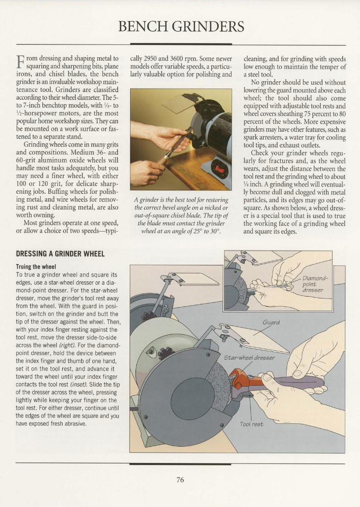
BENCH GRINDERS
f, rom dressing and shaping metaltoI squaring and sharpening bits, planeirons, and chisel blades, the benchgrinder is an invaluable worlshop main-tenance tool. Grinders are classifiedaccording to their wheel diameter. The 5-to 7-inch benchtop models, with %- to%-horsepower motors, are the mostpopular home workshop sizes. They canbe mounted on a work surface or fas-tened to a seoarate stand.
Grinding wheels come in many gritsand compositions. Medium 36- and60-grit aluminum oxide wheels willhandle most tasks adequately, but youmay need a finer wheel, with either100 or 120 grit, for delicate sharp-ening jobs. Buffing wheels for polish-ing metal, and wire wheels for remov-ing rust and cleaning metal, are alsoworth owning.
Most grinders operate at one speed,or allow a choice of two speeds-typi-
DRESSING A GRINDER WHEELTruing the wheelTo true a gr inder wheel and square i tsedges, use a star-wheel dresser or a dia-mond-point dresser. For the star-wheeldresser, move the grinder's tool rest awayfrom the wheel. With the guard in posi-t ion, switch on the gr inder and butt thetip of the dresser against the wheel. Then,with your index finger resting against thetool rest, move the dresser side-to-sideacross the wheel (right). For the diamond-point dresser, hold the device betweenthe index f inger and thumb of one hand,set i t on the tool rest, and advance i ttoward the wheel unt i l your index f ingercontacts the tool rest (inset). Slide the tipof the dresser across the wheel, pressingl ight ly whi le keeping your f inger on thetool rest. For either dresser, continue untilthe edges of the wheel are square and youhave exoosed fresh abrasive.
cally 2950 and 3600 rpm. Some newermodels offer variable speeds, a particu-larly valuable option for polishing and
A grinder is the best tool for restoringthe correct bevel angle on a nicked orout-of-square chisel blade. The tip ofthe blade must contact the grinderwheel at an angle of 25" to 30".
cleaning, and for grinding with speedslow enough to maintain the temper ofa steel tool.
No grinder should be used withoutlowering the guard mounted above eachwheel; the tool should also comeequipped with adjustable tool rests andwheel covers sheathing 75 percent to 80percent of the wheels. More expensivegrinders may have other features, such asspark arresters, a water tray for coolingtool tips, and exhaust outlets.
Check your grinder wheels regu-larly for fractures and, as the wheelwears, adjust the distance between thetool rest and the grinding wheel to aboutr/tinch. A grinding wheel will eventual-ly become dull and clogged with metalparticles, and its edges may go out-of-square. As shown below, a wheel dress-er is a special tool that is used to truethe working face of a grinding wheeland square its edges.
76
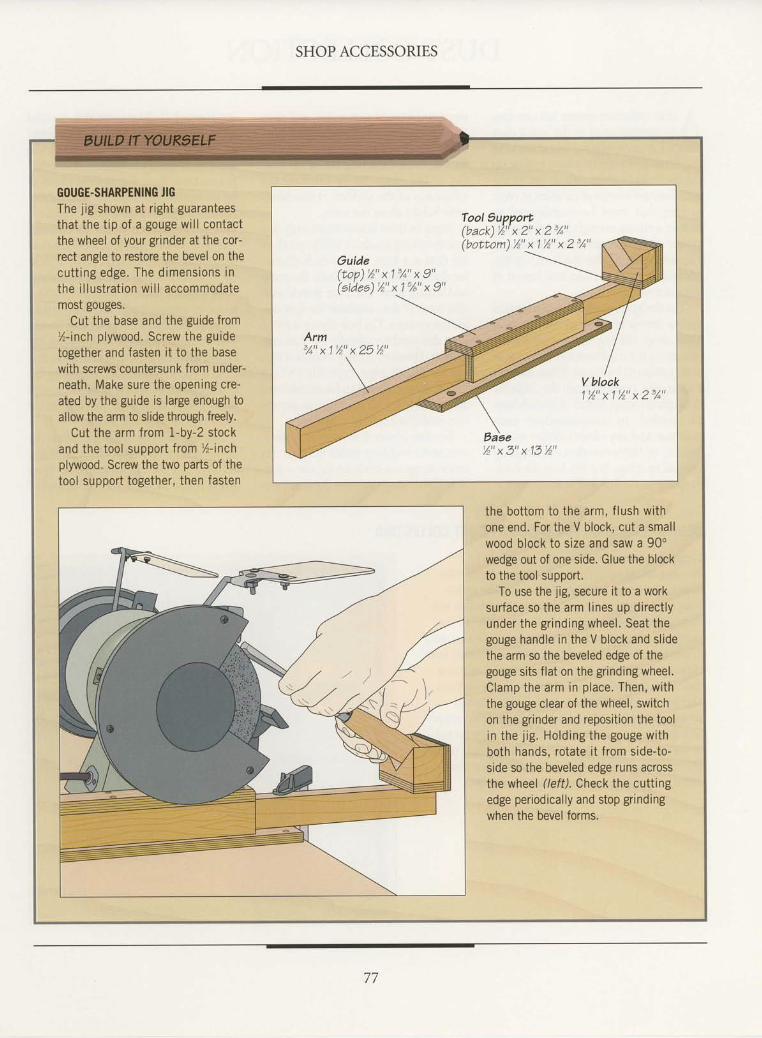
SHOP ACCESSORIES
U^
GOUGE.SHARPENING JIGThe jig shown at right guaranteesthat the t ip of a gouge wi l l contactthe wheel of your grinder at the cor-rect angle to restore the bevel on thecut t ing edge. The d imens ions inthe i l lustrat ion wi l l accommodatemosr gouges.
Cut the base and the guide from%-inch plywood. Screw the guidetogether and fasten it to the basewith screws countersunk from under-neath. Make sure the opening cre-ated by the guide is large enough toallow the arm to slide through freely.
Cut the arm from 1-by-2 stockand the tool support f rom %-inchplywood. Screw the two parts of thetool support together, then fasten
the bottom to the arm, f lush withone end. For the V block, cut a smallwood block to size and saw a 90"wedge out of one side. Glue the blockto the tool support.
To use the jig, secure it to a worksurface so the arm l ines up direct lyunder the gr inding wheel. Seat thegouge handle in the V block and slidethe arm so the beveled edge of thegouge sits flat on the grinding wheel.Clamp the arm in place. Then, withthe gouge clear of the wheel, switchon the grinder and reposition the toolin the j ig . Ho ld ing the gouge w i thboth hands, rotate it from side-to-side so the beveled edge runs acrossthe wheel (left). Check the cuttingedge periodically and stop grindingwhen the bevel forms.
Tool 9upport(back) '1 "x2"x2 '1"(bo t tom)%"x1%"x2 ' /o "
Ouide( r o p ) % " x 1 % " x 9 "(a tdee ) ' h "x1u /a "x9 "
77
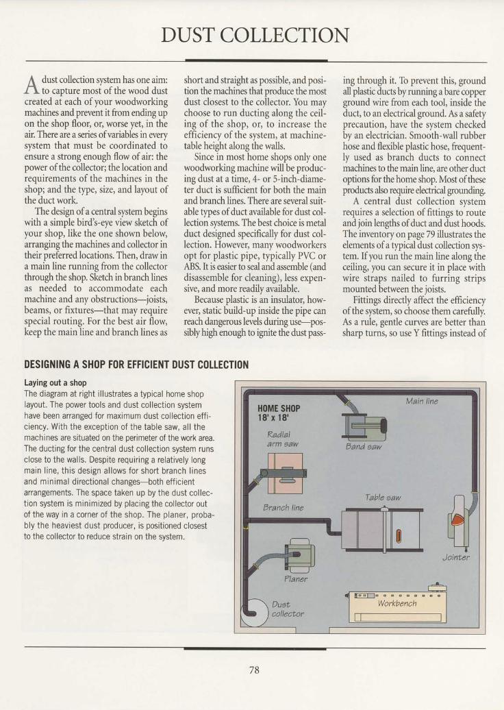
DUST COLLECTION
A dust collection system has one aim:A to capture mosiof the wood dustcreated at each ofyour woodworkingmachines and prevent it from ending upon the shop floor, or, worse yet, in theair. There are a series ofvariables in everysystem that must be coordinated toensure a strong enough flow ofair: thepower of the collector;the location andrequirements of the machines in theshop; and the type, size, and layout ofthe duct work.
The design ofa central system beginswith a simple bird's-eye view sketch ofyour shop, like the one shown below,arranging the machines and collector intheir preferred locations. Then, draw ina main line running from the collectorthrough the shop. Sketch in branch linesas needed to accommodate eachmachine and any obstructions-joists,beams, or fixtures-that may requirespecial routing. For the best air flow,keep the main line and branch lines as
short and straight as possible, and posi-tion the machines that produce the mostdust closest to the coilector. You maychoose to run ducting along the ceil-ing of the shop, or, to increase theefficiency of the system, at machine-table height along the walls.
Since in most home shops only onewoodworking machine will be produc-ing dust at a time, 4- or 5-inch-diame-ter duct is sufficient for both the mainand branch lines. There are several suit-able types ofduct available for dust col-lection systems. The best choice is metalduct designed specifically for dust col-lection. However, many woodworkersopt for plastic pipe, typically PVC orABS. It is easier to seal and assemble (anddisassemble for cleaning), Iess expen-sive, and more readily available.
Because plastic is an insulator, how-ever, static build-up inside the pipe canreach dangerous levels during use-pos-siblyhigh enough to ignite the dust pass-
ing through it. To prevent this, groundall plastic ducts by running a bare copperground wire from each tool, inside theduct, to an electrical ground. As a safetyprecaution, have the system checkedby an electrician. Smooth-wall rubberhose and flexible plastic hose, frequent-ly used as branch ducts to connectmachines to the main line, are other ductoptions for the home shop. Most of theseproducs also require electrical grounding.
A central dust collection systemrequires a selection offittings to routeand join lenghs of duct and dust hoods.The inventory on page 79 illustrates theelements of a qpical dust collection sys-tem. If you run the main line along theceiling, you can secure it in place withwire straps nailed to furring stripsmounted between the joists.
Fittings directly affect the efficiencyof the system, so choose them carefully.As a rule, gentle curves are better thansharp turns, so use Y fittings instead of
DESIGNING A SHOP
Laying out a shop
F()R EFFICIENT DUST C()LTECTION
The diagram at right il lustraies a typical home shoplayout. The power tools and dust collection systemhave been arranged for maximum dust collection eff i-c iency. With the except ion of the table saw, al l themachines are situated on the perimeter of the work area.The ducting for the central dust collection system runsclose to the wal ls. Despite requir ing a relat ively longmain l ine , th is des ign a l lows fo r shor t b ranch l inesand minimal direct ional changes-both eff ic ientarrangements. The space taken up by the dust col lec-t ion system is minimized by placing the col lector outof the way in a corner of the shop. The planer, proba-bly the heaviest dust producer, is positioned closestto the collector to reduce strain on the svstem.
78
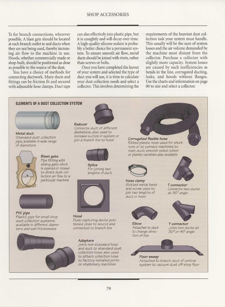
SHOP ACCESSORIES
Ts for branch connections, whereverpossible. A blast gate should be locatedat each branch outlet to seal ducts whenthey are not being used, thereby increas-ing air flow to the machine in use.Hoods, whether commercially made orshop-built, should be positioned as closeas possible to the source of the dust.
You have a choice of methods forconnecting ductwork. Many ducts andfittings can be friction fit and securedwith adjustable hose clamps. Duct tape
can also effectively join plastic pipe, butit is unsightly and will decay over time.A high-quality silicone sealant is proba-bly a better choice for a permanent sys-tem. To ensure smooth air flow metalducts should be joined with rivets, ratherthan screws or bolts.
Once you have completed the layoutofyour system and selected the type ofduct you will use, it is time to calculateyour dust collection needs and select acollector. This involves determining the
requirements of the heaviest dust col-lection task vour svstem must handle.This usually'will bi the sum of systemlosses and the air volume demanded bythe machine most distant from thecollector. Purchase a collector withslightly more capacity. System lossesare caused by such inefficiencies asbends in the line, corrugated ducting,leaks, and hoods without flanges.Use the charts and information on page80 to size and select a collector.
ETEMENTS (lF A DUST COTTECTION SYSTEM
Reduaer
Metal duct)tanda rd duat aollectionpipe; available in wide ranqe'of
diametera
Connecta duct of differentdiametere; alao used toincreaee auction in oyatem orioin a branah line to hood Corrugated fl exible hoae
Kibbed plaatic hose uaed for ahortruns or to connect machinea f,omain duct: smooth-aided rubber
Elaet' gate?ipe fittin7 withalidin7 qate whichia opened or cloaedto direat.duat col-lection air flow to apartiaular machine
SpliceFor joinin6 twolen4tha of duct
HoodD uat- c a pt u ri n4 d evice po ai'tioned cloee to aource andconnected to branch line
or plaatic varietiea aloo available
ffi\--J_ I'
Hoee alamp
!9lotted metal band T aonneatorand acrew ueed to Connecte two ductejoin two len4the of at 90" anqleduct or hoae
PVC pipePlastic pipe for emall ehopduat, collection system6;available in different diame-tere and wall thiakneasea
Elbow Y conneatorAtt,achee to duc-t' Joina two ducte atto chan1e direc- 3Oo or 45" an6letion of line
AdaptereJoina non-atandard hoseand duat to atandard dustcolleotion hoae: also uaedto abtach collection hoaeto facto ry- i n eta ll ed po rteon etationarv maohines
Floor aweepAttached to branch duct of centraleyetem to vacuum duat off ahop floor
79

SHOP ACCESSORIES
CATCUTATING DUST C(|LTECTI(|N NEEDS
Determining static pressure lossDust collectors are rated by their ability to (1) EOU|VAIEI{T TENGTH 0F SYSTEM EIEMENTSmove a certain number of cubic feet of air per Duct or Fifting Equivalent Lengh, in Feetminute (cfm) against a specif ic stat ic pres-sure. The most important variable to keep in Smooth-wall pipe Actual length
mind when choosing a dust collector for your Corrugated pipe or hose 1.5 x actual len$h
shop is static pressure loss, which is a mea- Unflanged duct, hose, or hood connections 10sure of the friction air encounters as it passes 90" sharp elbow 20through a duct. The longer the ducting and themore numerous the system rosses, the greater 90o curved elbow 10
the static Dressure loss. To determine the 90" hose bend 10
size of collector you need, calculate the static 45' curved elbow 5pressure loss for the heaviest collection task 45" hose bend 5in the shop. In the diagram on page 78, it isthe jointer. The fol lowing calculat ions are Side leg of 90" T 20
based on it. For your own shop, you may need Side leg of 45" Y 5
to do the calculat ions for a few machines-those farthest from the collector and at theend of branch lines-and choose a collectorbased on the highest result you obtain. (2) AIR EXHAUST V0LUME RE0UIREMENTS FOR MACHINES
Start with chart 1 (right, top) to calculate Machine Cubic Feet per Minute (CFM)the equivalent length of the ducting runningto the machine. In our example, there are Jointer @-r2') 300
45 straight feet of smooth 4-inch-diameter Disc sander (up to 12") 300duct and two 90'curved elbows. The equiv- Vertical belt sander (up to 6") 350alent length therefore is: 45 feet + 20 feet = Band saw (up to 2" blade) 40065 feet. Then use chart2 (middle) to deter-mrne rne exnausr reourremenrs rn cTm oTrne Table saw (up to 16") 300
machine; for the jointer, it is 300 cfm. Radial arm saw 350Finally, use chart 3 (bottom)to determine Planer (up to 20") 400
static pressure loss for dust collection at themachine. choose from either the third or fourth
Shaper (%" spindle) 300
column of the chart depending on whether Shaper (1" spindle) 500
the machine is joined to a main- l ine duct Lathe 500(3500 feet per minute of air velocity, or fpm) Floor sweep 350or a branch line (4000 fpm). In this example, Drill press 3OOa 300-cfm machine connected to a 4- inch-diameter main line has a static oressure loss Jig saw 300
of .05 inches per foot. Thus the static pres-sure loss for this jointer is: 65 feet x .05inches/foot = 3.25 inches. Add two inchesfor unmeasured losses like air leaks and the (3) STATIC PRESSURE L(ISS PER F00T 0F DUCT AT 3500 Al{D 21000 FPMvalue rises to 5.25 inches. The shop on page CFM Duct diameter 3500 fpm 4000 fpm78 would need a col lector with a 300 cfmrating at 5.25 inches of static pressure. A 300 4' '05 in/ft '07 in/ft
system 20 percent larger would allow for 350 4u '05 in/ft .07 in/ft
future expansion. 400 4' ,05 in/ft .06 in/ft
500 5u .04 in/ft .06 in/ft
80
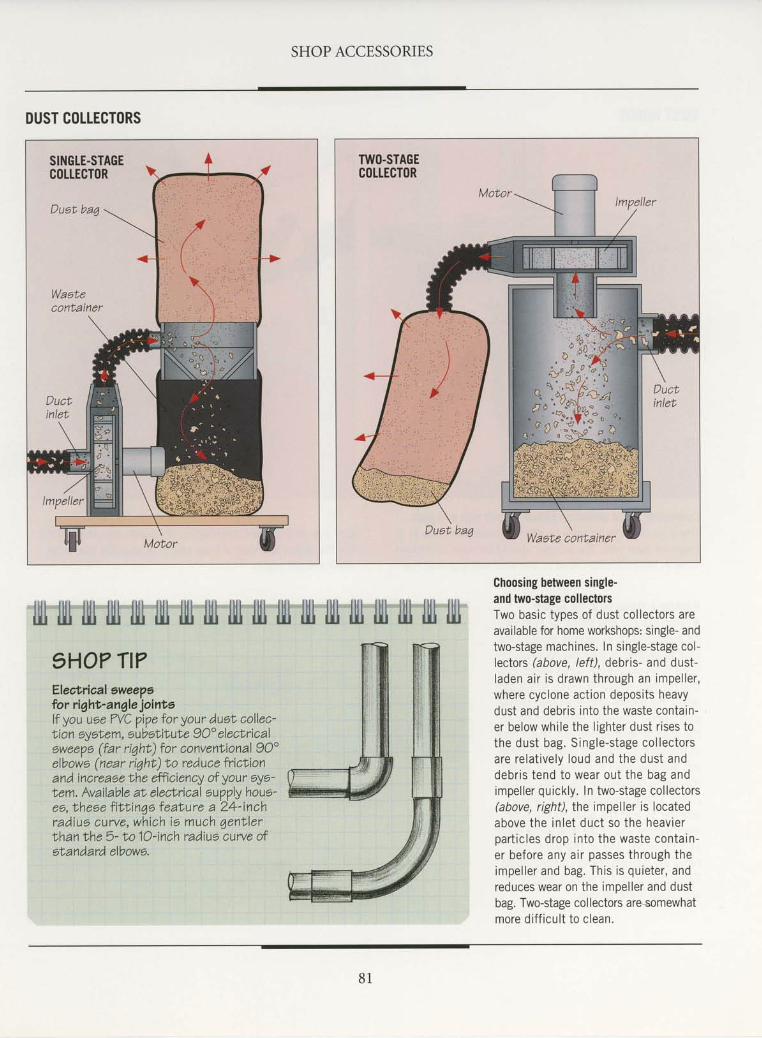
SHOP ACCESSORIES
DUST COLTECTORS
lllt illl llll ilt1 ill llll llll llll lll lll IllJ llll llll llil llll llll llil lllJ1HO? TI?Electrioal ewee?6lor riqht-angle jointolf you uee ?VC pipe tor your duet collec-Lion 6yoNem, substit'uhe 9O" electricalewee?o (far riqht) for convenlional 90"elbowe (near riqht) to reduce fricLionand increase lhe efficiency of your oye-tem. Available al elecNrical oupply houe'ee, Nhese f i t t in4e feaNure a 24-inchradius curve, which ie much qent ' lerthan Ihe 5- to |O-inch radius curve ofetandard elbowe,
Choosing between single-and two-stage collectorsTwo basic types of dust col lectors areavailable for home workshops: stngle- andtwo-stage machines. In single-stage col-leclors (above, /eff), debris- and dust-laden a i r i s d rawn th rough an impe l le r ,where cyclone act ion deposits heavydust and debris into the waste contain-er below whi le the l ighter dust r ises tothe dus t bag. S ing le -s tage co l lec to rsare re la t i ve ly loud and the dus t anddebr is tend to wear ou t the bag andimpel ler quickly. In two-stage col lectors(above, right),Ihe impeller is locatedabove the in le t duc t so the heav ie rpar t i c les d rop in to the waste conta in -er before any air passes through theimpe l le r and bag. Th is i s qu ie te r , andreduces wear on the impel ler and dustbag. Two-stage collectors are somewhatmore di f f icul t to clean.
8 1
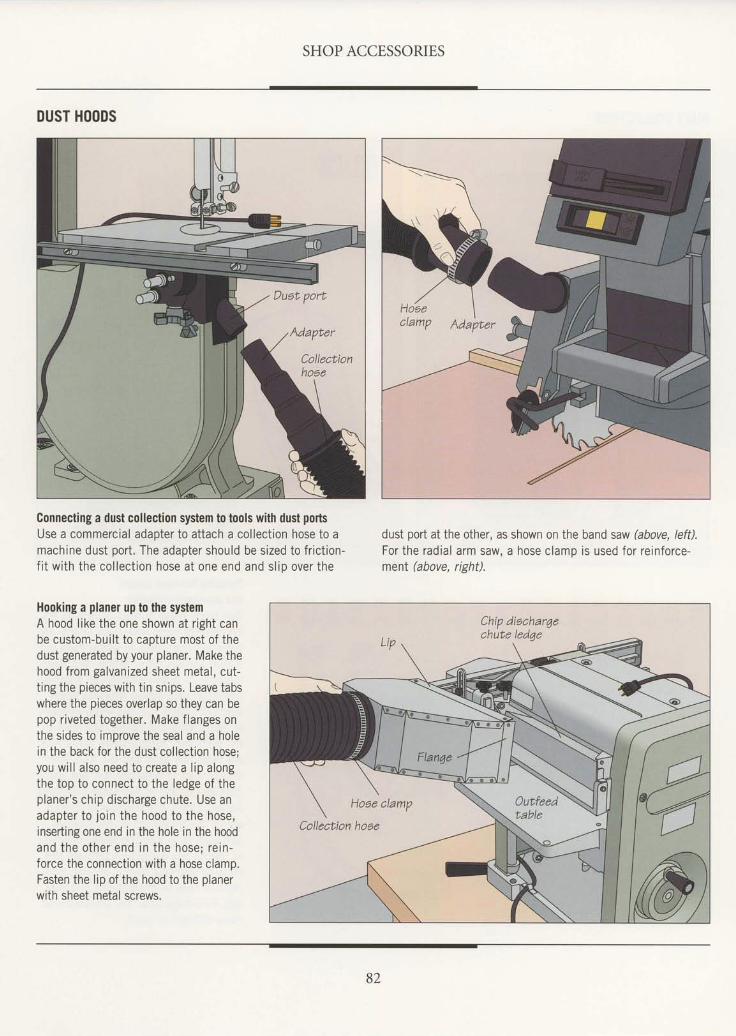
SHOP ACCESSORIES
DUST HOODS
Connecting a dust collection system to tools with dust portsUse a commercial adapter to attach a col lect ion hose to amachine dust port . The adapter should be sized to fr ict ion-f i t w i th the co l lec t ion hose a t one end and s l io over the
Hooking a planer up to the systemA hood l ike the one shown at r ight canbe custom-bui l t to caoture most of thedust generated by your planer. Make thehood from galvanized sheet metal , cut-ting the pieces with tin snips. Leave tabswhere the pieces overlap so they can bepop r iveted together. Make f langes onthe sides to imorove the seal and a holein the back for the dust col lect ion hose;you wi l l a lso need to create a l ip alongthe top to connect to the ledge of theplaner 's chip discharge chute. Use anadapter to jo in the hood to the hose,inseding one end in the hole in the hoodand the o ther end in the hose; re in -force the connection with a hose clamo.Fasten the lip of the hood to the planerwith sheet metal screws.
dust port at the other, as shown on the band saw (above, left).For the radial arm saw, a hose clamp is used for reinforce-menl (above, right).
Adapter
CollecLionhoae
82
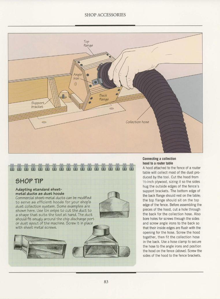
SHOP ACCESSORIES
fitl rlll llll llt tlll llll llll llll llll llll llll fiIl llll llll llll llll l]I1 llll1HO? TI?Adapt inq st andard sheet'metal ducts as dust,hoodeCommercial eheet-met al duc|'s can be modifiedLo eerve ae eff ic ient hoode tor your ohop'eduet, collecLion oyofem. Some examplea areshown here. Uee Lin snios I'o cuN Nhe ducL t'oa ehape thaN ouit6 the tool aI hand. The ducNshoulA fi1; enuqly around the chip diocharqe Vortor dusN opout of the machine. )crew iL in Vlace
Connecting a collectionhood to a router tableA hood attached to the fence of a routertable wi l l col lect most of the dust pro-duced by the tool . Cut the hood froml/z-inch plywood, sizing it so the sideshug the outside edges of the fence'ssupport brackets. The bottom edge ofthe back flange should rest on the table;the top f lange shou ld s i t on the topedge of the fence. Before assembling thepieces of the hood, cut a hole throughthe back for the col lect ion hose. Alsobore holes for screws through the sidesand screw angle i rons to the back sothat their inside edges are flush with theopening for the hose. Screw the hoodtogether, then f i t the col lect ion hosein the back. Use a hose clamp to securethe hose to the angle irons and positionthe hood on the fence bbove). Screw thesides of the hood to the fence brackets.
wibh eheet melal screwe.
B3
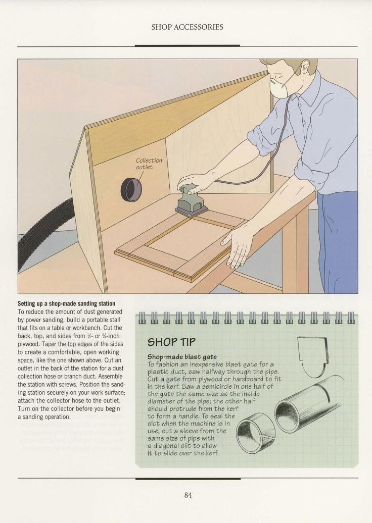
SHOP ACCESSORIES
Setting up a shop-made sanding stationTo reduce the amount of dust generatedby power sanding, bui ld a portable stal lthat fits on a table or workbench. Cut theback, top, and sides from %- or %-inchplywood. Taper the top edges of the sidesto create a comfortable, open workingspace, like the one shown above. Cut anoutlet in the back of the station for a dustcollection hose or branch duct. Assemblethe station with screws. Position the sand-ing station securely on your work surface;attach the col lector hose to the out let .Turn on the col lector before you begina sanding operat ion.
1HO? TI?Shop-madeblaot gateTo faohion an inexpeneive blael qabe for aVlael ic ducl , saw halfway Ihrouqh rhe Vipe.Cut a 4aIe from plywood or hardboard to fiiin lhe kerf .)aw a eemicircle in one half of
llll tl|t llll Il11 l]il lllr llll fiil lll1 lllr llll lll} l|ll llll llr llll lll lril
the qate Ihe same eize as lhe ineidediamet er of Nhe piVe; lhe olher haltshould orolrude from the kefrLo form a handle. To eeal theslol when |he machine ie inuse, cuL a eleeve lrom lheeame size of pipe wi lha d iaqona l s l iL to a l lowiL t o elide over Nhe kefr.
84

PORTABLE DUST COLLECTION
I central dust collection system mayA sound like overkill to the craftsmanwith a small home shop. Although suchsystems are generallymore efficient thanindependent collectors, they can be cost-ly and consume considerable space. Ifyour shop area is restricted, and onlyone machine will be operated at a time,consider a portable dust collector.
Many types of portable dust collec-tors are available. Most are strongenough to power a central system, yetlight enough to be toted around theshop. Ifyou are planning to set up aportable collection system, shop aroundfor the most transportable collector thatcan handle your needs. Keep in mindthat you may want to expand to a cen-tral system later.
Many home woodworkers will findthat a shop vacuum, although not ideal,can do a satisfactory job most of the timeif you are willing to work around the
Although you can hook up a band smuto a central dust collection system,another solution is to attach it to a
portable shop vacuum. Thevacuum'shose can oftenbe slipped around anexistingport on the machine using
a simple commercial reducer.
drawbacls. Shop vacuums are designedto move a small volume of air at highvelocity through a small-diameter hose.Dust collectors, on the other hand,move a large amount of air at a lowerspeed. A shop vacuum dust hood, there-fore, should be positioned very close tothe tool. Larger chips will tend to clogvacuum hoses, requiring frequent clean-ing. And, vacuums powered by univer-sal motors tend to wear out quickly.Models with induction-type electricmotors will last longer, but cost morethan a portable dust collector of thesame Dower.
If there is no dust collection system-portable or central-in your shop, trythe methods described starting on page86 to control airborne dust. These meth-ods are also effective supplements tocollectors that suck up a majority ofshop dust, but still leave some particlesfloating in the air.
AN AUXILIARY PORTABLE DUST C(ILLECTION SYSTEMExpanding a dust collecto/s capacityYou can more than double the capacityof your portable dust collector or shopvacuum by attaching a 55-gallon drum ora large plastic barrel as a mid-stage col-lector. Install plastic intake and exhaustoorts on the drum as shown at left andmount a hose to the intake port on thedrum to collect wood dust and chips. The90" elbow on the intake port will create acyclone effect inside the barrel, forcingchips and heavier sawdust against thewalls of the barrel. Lighter dust will bedrawn through the exhaust port into theshop vacuum or dust collector. For easyassembly and disassembly, use pipe fit-tings that form a friction fit with the hosefrom your vacuum or collector.
85
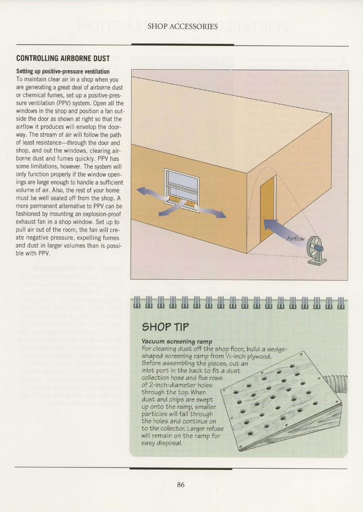
SHOP ACCESSORIES
CONTROLLING AIRBORNE DUSTsetting up positive-pressure ventilationTo maintain clear air in a shop when youare generating a great deal of airborne dustor chemical fumes, set up a positive-pres-sure ventilation (PPV) system. Open all thewindows in the shop and position a fan out-side the door as shown at right so that theairflow it produces will envelop the door-way. The stream of air will follow the pathof least resistance-through the door andshop, and out the windows, clear ing air-borne dust and fumes quickly. PPV hassome limitations, however. The system willonly function properly if the window open-ings are large enough to handle a sufficientvolume of air. Also, the rest of your homemust be well sealed off from the shoo. Amore permanent alternative to PPV can befashioned by mounting an explosion-proofexhaust fan in a shop window. Set up topul l air out of the room, the fan wi l l cre-ate negat ive pressure, expel l ing f umesand dust in larger volumes than is possi-ble with PPV.
fill llll tlt'llt llt'lll-llll tII iltt'Ixl IIt llt ll|l'lllt lll fil'fiI'l||l1HO? TI?Vaauum eareening rampFor cleaninq dust off Xhe ohop floor, build a wedqe-a L ^ a ^ - ) z r q a ^ q i a ^ - ^ * ^ t - ^ ^ 1 / ^ i - - r ^ 1 . , , , , ^ ^ - Jehaped ecreenin7 ramV froml/z-inch plywood.Oefore aeeemblinq Ihe piecee, cut aninlet porl in Ihe backto fit a dustcollection hose and five roweof 2-in ch - di am eLer h oleslhrouqh the Iop.Whendust and chiVo are 6we\u? onbo the ramp, emallerparliclee will f all throuqhlhe holee and conNinue onIo the colleclor. Larger refusewill remain on bhe ramo toreaey diopoeal.
86
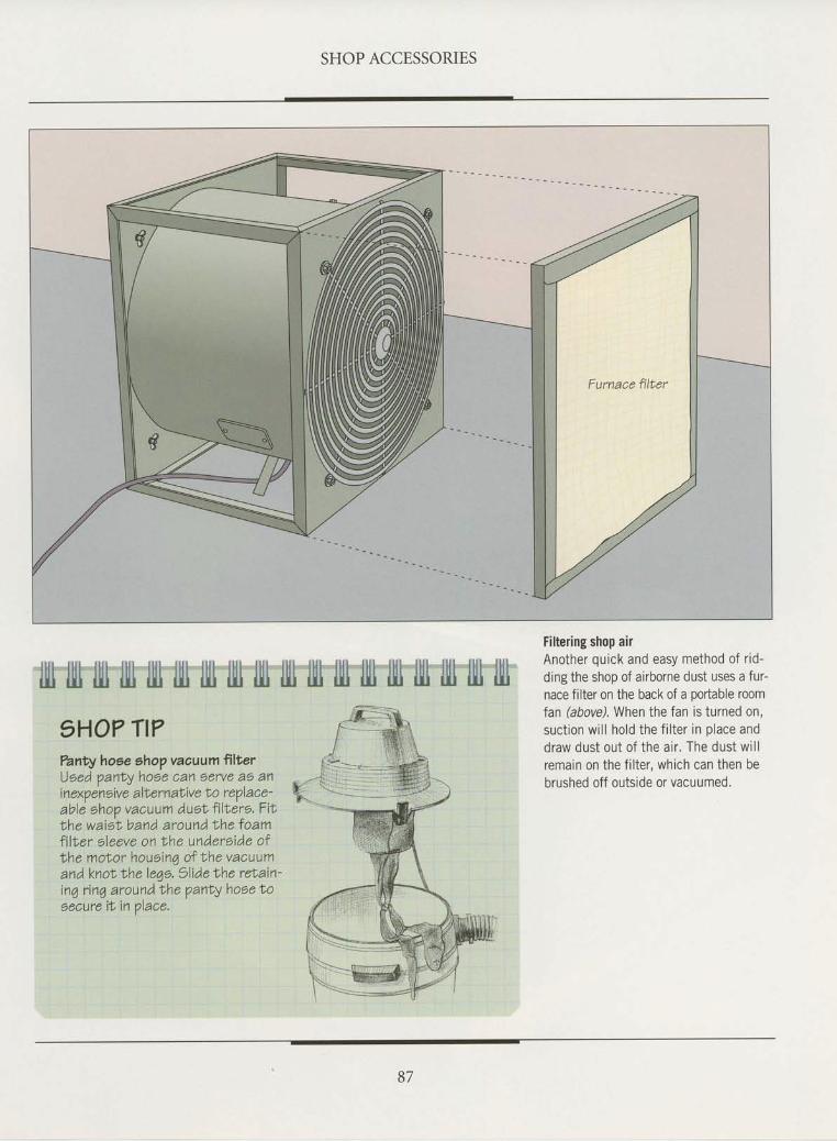
SHOP ACCESSORIES
l|Il illl llll llll lll llli llll llll llll llll llll llll llll llll llll lltl llll l]l}1HO? Tt??anty hoee ahop vacuum ftlt'erUoed panty hoee can oerve ao aninexpeneive alt'ernaLive lo replace-able shop vacuum dust' fi lNero. Fitthe waieL band around Ihe loamfilf,er sleeve on Lhe undereide oflhe molor houein4 of the vacuumand knot Ihe lege. )lide the ret'ain-inq rinq around Ihe panty hose t'oaecure iN in place.
Filtering shop airAnother quick and easy method of r td-ding the shop of airborne dust uses a fur-nace filter on the back of a podable roomfan (above). When the fan is turned on,suct ion wi l l hold the f i l ter in place anddraw dust out of the air . The dust wi l lremain on the filter, which can then bebrushed off outside or vacuumed.
87
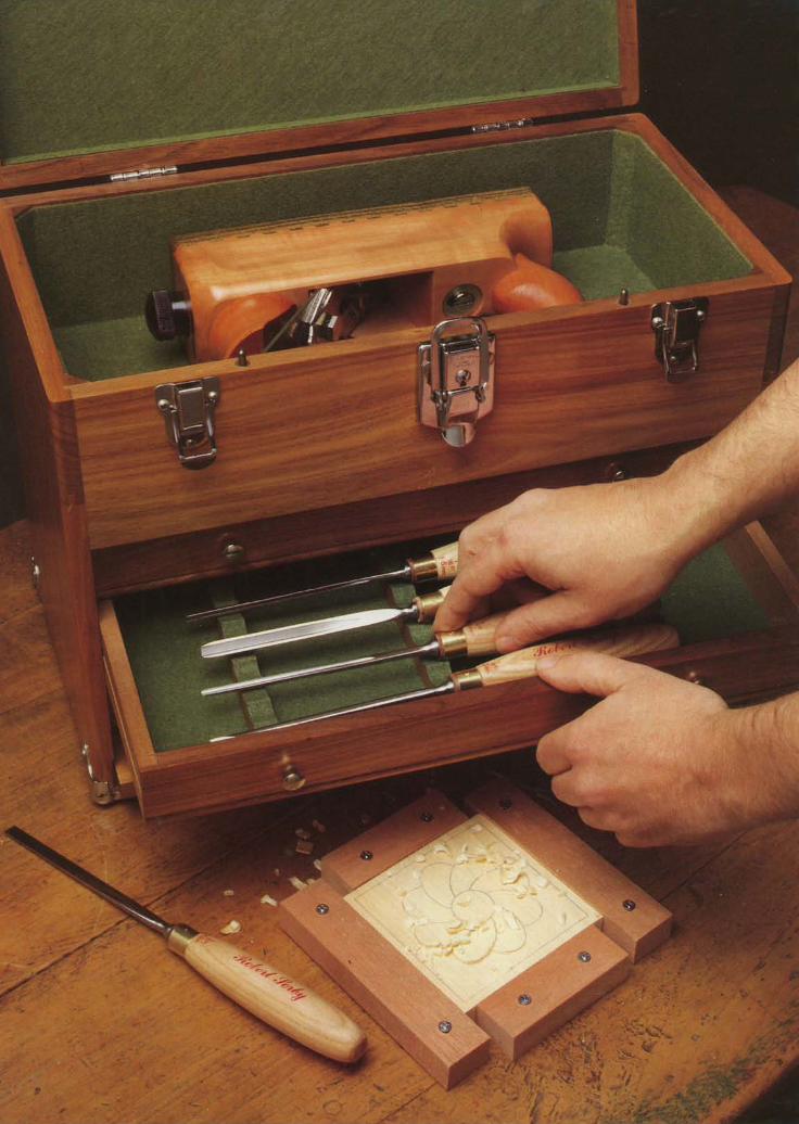

STORAGE,
n'd'ub'laccumula'fesliffi# frfi*[T"i!,{if.#i-.i'*$
astonishing rate: Lumbersaws, saw blades, drillsplanes, clamps, chisels, filt
conveniently available when need- Flammable productslikelacquers, shellacs, market, but you can build a tool
ed-and out of the way when not. and paint thinners require sltecial attention. cabinet customized to- your needsAdd to these the lumber scraps, Storiig these items in a-doubfe-lined, explosion- easily and inexpensively (p^qT: ?!)
locks, hinges, screws, nails, spire priof steet cabinet is one sensible solution. The designshown on page 98 ffillspars,'and lontainers haHill of fin two needs in one: a storage cabinetisher-all sure to be invaluable some day very soon-and you that folds down and serves as a-sturdy work surface. Hardwaremayhave the makings of a monumental stoiage problem. - can be sorted in drawers, subdivided into separate compart-
Adequate workh6p storage should accomilish two goalg: ments or, for greater "i:t!lt y, in glass containers. For toolsfooh and materials iliould bi kept within eaiy reach ofeach like clamps that are used all over the shop, consider awheeledoperation, andthe storage devices shouldencroachaslittleas rack(page 105)..pbssible on work space. lio matter what your particular needs, No matter what devices and techniques y. ou choose, youyou should find a number of storage ideas thit conserve space may find that proper storage not only provides more spacein this chapter.
- and conrrenience, but conveys a sense of order and. purpose
tn evaluating your own storage options begin by taklg two that ryill make your shop an even more pleasant and produc-inventories: oni'of your tools and materials and the other of tive place to work.
h * d * d p o * . ' t o o l s t h a t m u s t b e c o m m e r c i a l s t o r a g e d e v i c e s ' o n t h e. l
Whatever its size, a tool chest can serve as a cabinetmak-er's calling card. This portable carver's chest keeps toolsorganized" safe from damage, and within easy reach.
89
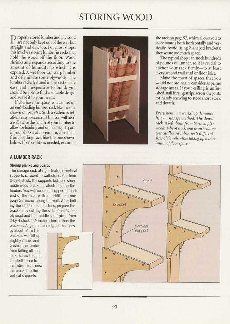
STORINGWOOD
p roperly stored lumber and plyr,voodI. are not onlykeptout ofthewaybutstraight and dry, too. For most shops,this involves storing lumber in racls thathold the wood off the floor. Woodshrinks and expands according to theamount of humidity to which it isexposed. A wet floor can warp lumberand delaminate some plywoods. Thelumber racks featured in this section areeasy and inexpensive to build; youshould be able to find a suitable designand adapt it to your needs.
Ifyou have the space, you can set upan end-loadinglumber racklike the oneshown on page 91. Such a system is rel-atively easy to construct but you will needa wall twice the lengh of your lumber toallow for loading and unloading. If spacein your shop is at a premium, consider afront-loading rack like the one shownbelow. If versatility is needed, examine
A LUMBER RACKStoring planks and boardsThe storage rack at right features verticalsupports screwed to wall studs. Cut from2-by-4 stock, the supports buttress shop-made wood brackets, which hold up thelumber. You wi l l need one support at eachend o f the rack , w i th an add i t iona l oneevery 32 inches along the wall. After bolt-ing the supports to the studs, prepare thebrackets by cutting the sides from %-inchplywood and the middle shelf piece from2-by-4 stock 1% inches shorter than thebrackets. Angle the top edge of the sidesby about 5'so thebrackets wi l l t i l t upslightly (inset)andprevent the lumberfrom fal l ing off therack. Screw the mid-dle shelf piece tothe sides, then screwthe bracket io thevertical supports.
the rack on page 92, which allows you tostore boards both horizontally and ver-tically. Avoid using Z-shaped brackets;they waste too much space.
The typical shop can stock hundredsof pounds of lumbet so it is crucial toanchor your rack firmly-to at leastevery second wall stud or floor joist.
Make the most of spaces that youwould not ordinarily consider as primestorage areas.If your ceiling is unfin-ished, nail furring strips across the joistsfor handy shelving to store short stockand dowels.
Every item in a workshop demandsits own storage method. The dowelrack at left, built from 3/t-inch ply-wood, 1-by-4 stock and 6-inch-diam-eter cardboard tubes, sorts dffirentsizes of dowels while taking up a min-imum of floor space.
o
o
o
o
o
o
90
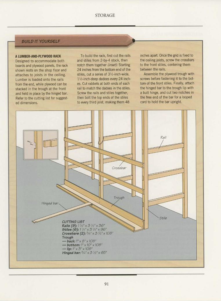
STORAGE
A TUMBER-AND.PTYWOOD RACKDesigned to accommodate bothboards and plywood panels, the rackshown rests on the shop floor andattaches to joists in the cei l ing.Lumber is loaded onto the rai lsfrom the end, while plywood can bestacked in the trough at the frontand held in place by the hinged bar.Refer to the cutting list for suggest-ed dimensions.
To build the rack, first cut the railsand stiles from 2-by-4 stock, thennotch them together (rnsef): Starting24 inches from the bottom end of thestiles, cut a series of 3%-inch-wide,1%-inch-deep dadoes every 24 inch-es. Cut rabbets at both ends of eachrail to match the dadoes in the stiles.Screw the rails and stiles together,then bolt the top ends of the stilesto every third joist, making them 48
inches apart. Once the grid is fixed tothe ceiling joists, screw the crossbarsto the front stiles, centering thembetween the rails.
Assemble the plywood trough withscrews before fastening it to the bot-tom of the front stiles. Finally, attachthe hinged bar to the trough lip witha butt hinge, and cut two notches inthe free end of the bar for a loopedcord to hold the bar upright.
CUTflNO LI5TRails (9): 1 1/2" x 31/2" x 36"?tilea (6): 'l 1/2" x 31/2" x 96"Croeebars (2)t 3,/+" x 3t/2" x 1OB"Trough- back 1" x B" x 1OB"- bottomt 1" x 10" x 1OB"- lip: 1" x 3" x 1OB"Hinged bar: 3/c" x 3 1/2" x 65"
9 l
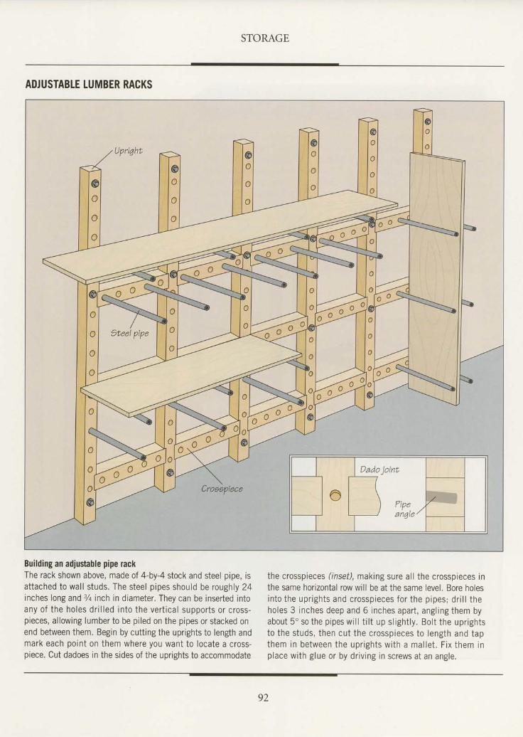
STORAGE
ADJUSTABTE LUMBER RACKS
Building an adjustable pipe rackThe rack shown above, made of 4-by-4 stock and steel pipe, isattached to wal l studs. The steel pipes should be roughly 24inches long and % inch in diameter. They can be inserted intoany of the holes dr i l led into the vert ical supports or cross-pieces, allowing lumber to be piled on the pipes or stacked onend between them. Begin by cutting the uprights to length andmark each point on them where you want to locate a cross-piece. Cut dadoes in the sides of the uprights to accommodate
the crosspieces ( inset), making sure al l the crosspieces inthe same horizontal row will be at the same level. Bore holesin to the upr igh ts and c rossp ieces fo r the p ipes ; d r i l l theholes 3 inches deep and 6 inches apart , angl ing them byabout 5' so the pipes wi l l t i l t up sl ight ly. Bolt the uprightsto the studs, then cut the crosspieces to length and tapthem in be tween the upr igh ts w i th a mal le t . F ix them inplace with glue or by dr iv ing in screws at an angle.
92
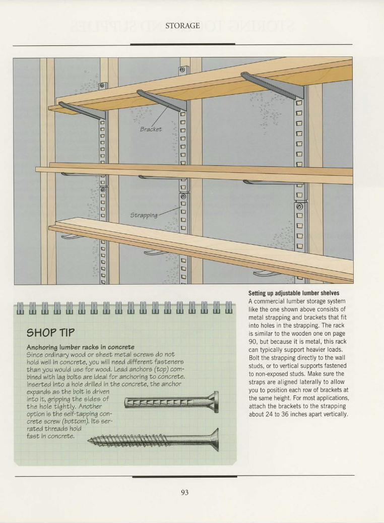
STORAGE
i l i l i l i l t t i l i i t t i l i l t t r r i l i i t i t i t i i l l l i t t r l i l l i l l l l i l l i l l l l l l i l l i l i r i l l lili i$ llt ii.l ul i$ iil d.u i$ {iJ t$ tti {ti l$ i$ iti i$ i.U
1HO? TI?Anahoring lumber raaka in aonareteeince ordinary wood or eheet melal ecrewe do noNhold well in concrele, you will need, d,ifferenf' faetenereNhan you would uee for wood. Lead, anchore (top) com-bined with laq bollo are ideal lor anchorin7 t'o concrel'e.lneerted into a hole drilled in I'he concreLe, Nhe anchor
Setting up adjustable lumber shelvesA commercial lumber storage systemlike the one shown above consists ofmetal strapping and brackets that f i tinto holes in the strapping. The rackis simi lar to the wooden one on page90, but because i t is metal , this rackcan typical ly support heavier loads.Bolt the strapping direct ly to the wal lstuds, or to vertical supports fastenedto non-exposed studs. Make sure thes t raps are a l igned la te ra l l y to a l lowyou to position each row of brackets atthe same height. For most applications,attach the brackets to the strappingabout 24 to 36 inches apart vertically.
exVands ae Nhe boll io driveninlo i t , qr ippinqtrhe eidee ofthe hole t iqhNly. AnotheroVtion ie the eell-LaVpin4 con-crele ocrew (bottom),lle eer-rated lhreade holdfasL in concreNe.
93
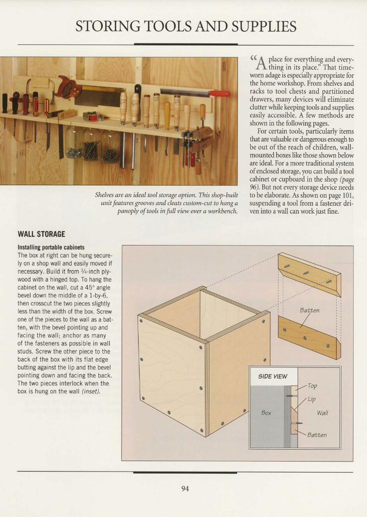
STORING TOOLS AND SUPPLIES
Shelves are an ideal tool storage option. This shop-builtunit features grooves and cleats custom-cut to hang a
panoply of took in full view oyer a workbench.
(( [ place for everything and every-
A thing in its place." That time-worn adage is especially appropriate forthe home workshop. From shelves andracks to tool chests and partitioneddrawers, many devices will eliminateclutter while keeping tools and supplieseasily accessible. A few methods areshown in the following pages.
For certain tools, particularly itemsthat are valuable or dangerous enough tobe out of the reach of children, wall-mounted boxes like those shown beloware ideal. For a more traditional systemofenclosed storage, you can build a toolcabinet or cupboard in the shop (page96).But not every storage device needsto be elaborate. As shown on page l0l,suspending a tool from a fastener dri-ven into a wall can work just fine.
WALL STORAGEInstalling portable cabinetsThe box at right can be hung secure-ly on a shop wall and easily moved ifnecessary. Build it from 3Z-inch ply-wood with a hinged top. To hang thecabinet on the wal l , cut a 45' anglebevel down the middle of a 1-by-6,then crosscut the two pieces slightlyless than the width of the box. Screwone of the oieces to the wall as a bat-ten, with the bevel point ing up andfac ing the wa l l ; anchor as manyof the fasteners as oossible in wal lstuds. Screw the other oiece to theback of the box with i ts f lat edgebutting against the lip and the bevelpoint ing down and facing the back.The two pieces inter lock when thebox is hung on the wal l ( inset).
SIDEVIEW
Wall
tsalten
94
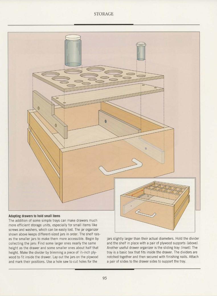
STORAGE
Adapting drawers to hold small itemsThe addit ion of some simple trays can make drawers muchmore eff ic ient storage units, especial ly for smal l i tems l ikescrews and washers, which can be easily lost. The jar organizershown above keeps different-sized jars in order. The shelf rais-es the smal ler jars to make them more accessible. Begin bycol lect ing the jars: Find some larger ones nearly the sameheight as the drawer and some smal ler ones about half thatheight. Make the divider by tr imming a piece of 7z- inch ply-wood to f it inside the drawer. Lay out the jars on the plywoodand mark their oositions. Use a hole saw to cut holes for the
jars sl ight ly larger than their actual diameters. Hold the dividerand the shelf in place with a pair of plywood supports (above).Another useful drawer organizer is the sliding tray (inseil. fhetray is a basic box that fits inside the drawer. The dividers arenotched together and then secured with finishing nails. Attacha pair of slides to the drawer sides to support the tray.
95
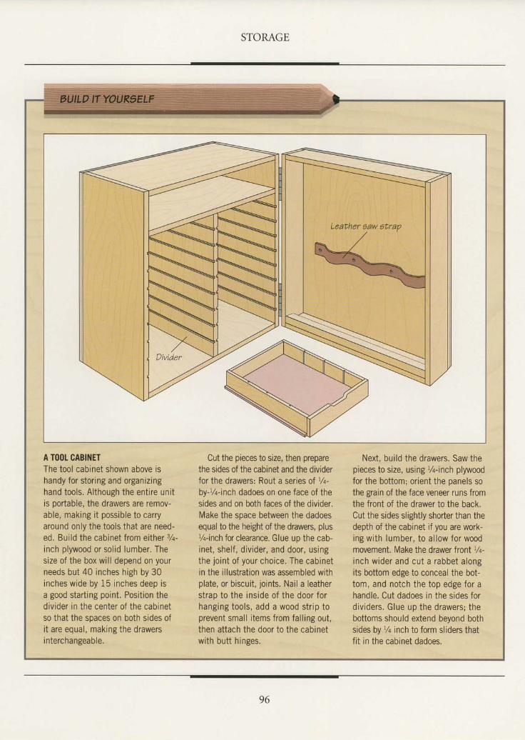
STORAGE
Leather eaw etrap
A TOOL CABINETThe tool cabinet shown above ishandy for storing and organizinghand tools. Al though the ent ire unitis portable, the drawers are remov-able, making i t possible to carryaround only the tools that are need-ed. Bui ld the cabinet from either 7a-inch plywood or sol id lumber. Thesize of the box will depend on yourneeds but 40 inches high by 30inches wide by 15 inches deep isa good starting point. Position thedivider in the center of the cabinetso that the soaces on both sides ofi t are equal, making the drawersi nterchangeable.
Cut the pieces to size, then preparethe sides of the cabinet and the dividerfor the drawers: Rout a series of 7+-by-%-inch dadoes on one face of thesides and on both faces of the divider.Make the space between the dadoesequal to the height of the drawers, plusYa-inch for clearance. Glue up the cab-inet, shelf , div ider, and door, usingthe joint of your choice. The cabinetin the illustration was assembled withplate, or biscuit, joints. Nail a leatherstrao to the inside of the door forhanging iools, add a wood str ip toprevent smal l i tems from fal l ing out,then attach the door to the cabinetwith butt hinges.
Next, build the drawers. Saw thepieces to size, using Vq-inch plywoodfor the bottom; orient the panels sothe grain of the face veneer runs fromthe front of the drawer to the back.Cut the sides slightly shorter than thedepth of the cabinet if you are work-ing with lumber, to al low for woodmovement. Make the drawer front 12-inch wider and cut a rabbet alongits bottom edge to conceal the bot-tom, and notch the top edge for ahandle. Cut dadoes in the sides fordividers. Glue up the drawers; thebottoms should extend beyond bothsides by Vq inch to form sl iders thatfit in the cabinet dadoes.
96
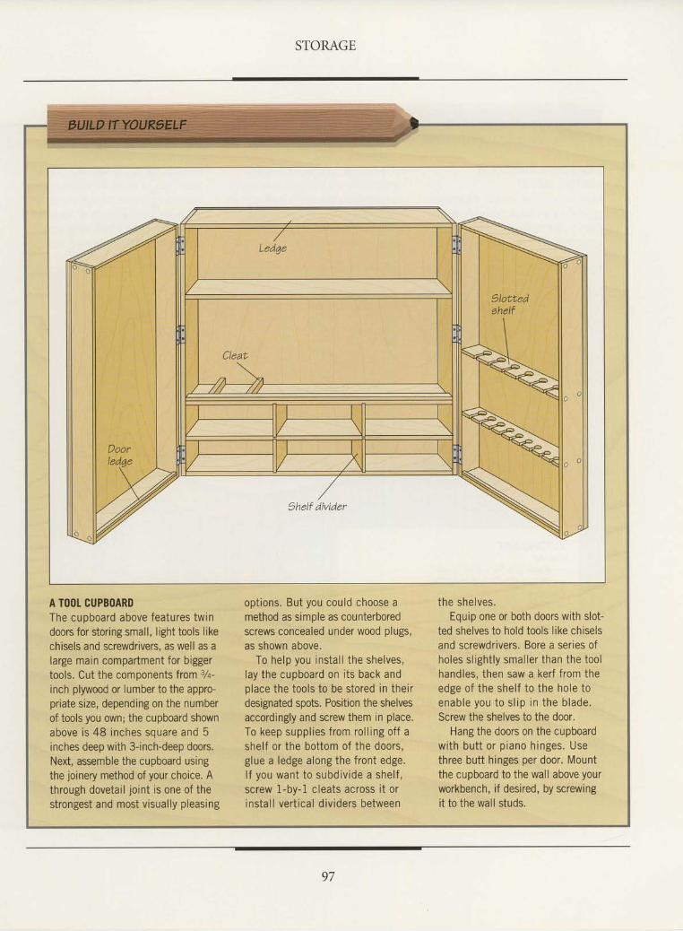
STORAGE
A TOOI- CUPBOARDThe cupboard above features twindoors for storing small, l ight tools likechisels and screwdrivers, as well as alarge main compartment for biggertools. Cut the components from 32-
inch plywood or lumber to the appro-priaie size, depending on the numberof tools you own; the cupboard shownabove is 48 inches souare and 5inches deep with 3-inch-deep doors.Next, assemble the cupboard usingthe joinery method of your choice. Athrough dovetai l jo int is one of thestrongest and most visually pleasing
opt ions. But you could choose amethod as simple as counterboredscrews concealed under wood plugs,as shown above.
To help you instal l the shelves,lay the cupboard on i ts back andolace the tools to be stored in theirdesignated spots. Position the shelvesaccordingly and screw them in place.To keep suppl ies from rol l ing off ashelf or the bottom of the doors,glue a ledge along the front edge.l f you want to subd iv ide a she l f ,screw 1-by-1 cleats across i t orinstal l vert ical div iders between
the she lves .Equip one or both doors with slot-
ted shelves to hold tools like chiselsand screwdrivers. Bore a series ofholes sl ight ly smal ler than the toolhandles, then saw a kerf f rom theedge of the shelf to the hole toenab le you to s l ip in the b lade.Screw the shelves to the door.
Hang the doors on the cupboardwi th bu t t o r p iano h inges . Usethree butt hinges per door. Mountthe cupboard to the wall above yourworkbench, if desired, by screwingit to the wall studs.
97
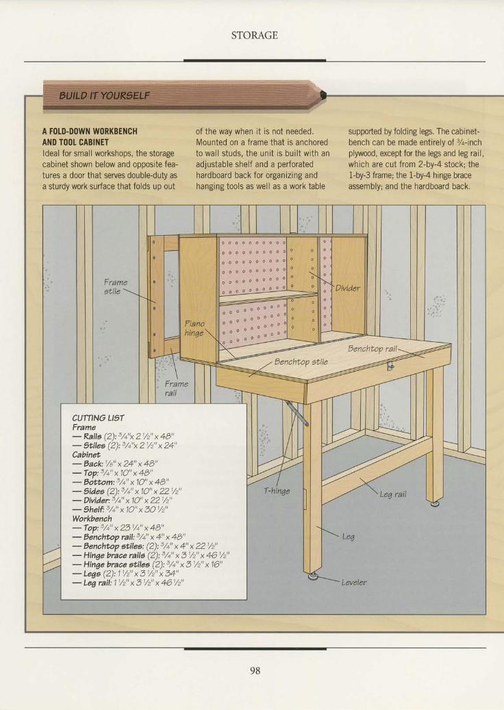
STORAGE
A FOLD-DOWN WORKBENCHAND TOOL CABINETldeal for small workshops, the storagecabinet shown below and opposite fea-tures a door that serves double-duty asa sturdy work surface that folds up out
of the way when it is not needed.Mounted on a frame that is anchoredto wal l studs, the unit is bui l t wi th anadjustable shelf and a perforatedhardboard back for organizing andhanging tools as well as a work table
supported by folding legs. The cabinet-bench can be made entirely of %-inchplywood, except for the legs and leg rail,which are cut from 2-by-4 stock; the1-by-3 frame; the 1-by-4 hinge braceassembly; and the hardboard back.
Frame
Fianohinge
o o o o o o o o o o
o o o o o o o o o
o o o o o o o o o o
o o o o o o o o o a
o o o o o o o o o o
o o o o o o o o o o
11 o o o o o o o
o o o o " " " : :
CUTTING LI9TFrame- Raile (2):3,/+"x 21/2" x 48"- Stilee (2):3/+"x 21/2" x 24"Cabinet- Back:1/a" x 24" x 48"- Top:3,/+" x 10" x 48"- Eottom:3,/+" x 10" x 48"- 1ides (2):3,/+" x 10" x 221,/2"- Divider:3,/q" x 10" x 221,/2"- thelf 3/+" x 10" x 3O1/2"Workbenah- Top:3,/+" x 23 1,/+" x 48"- Eenchtop rail:3/+" x 4" x 48"- Bencht'op atileo: (2):3/+" x 4" x 221/2"- Hinge brace rails (2):3/+" x 31/2" x 461/2"- Hinge brace stilea (2):3,/+" x 31/2" x 16"- Lege (2): 1 1/2" x 31/2" x 34"- Leg rail: 1 1/2" x 3 1/2" x 461/2"
9B
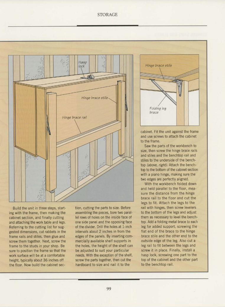
STORAGE
Build the unit in three steps, start-ing with the frame, then making thecabinet sect ion, and f inal ly cutt ingand attaching the work table and legs.Referring to the cutting list for sug-gested dimensions, cut rabbets in theframe rai ls and st i les, then glue andscrew them together. Nexi, screw theframe to the studs in your shop. Besure to position the frame so that thework surface will be at a comfortableheight, typically about 36 inches offthe floor. Now build the cabinet sec-
tion, cutting the parts to size. Beforeassembling the pieces, bore two paral-lel rows of holes on the inside face ofone side panel and the opposing faceof the divider. Drill the holes at l-inchintervals about 2 inches in from theedges of the panels. By inserting com-mercial ly avai lable shelf supports inthe holes, the height of the shelf canbe adjusted to sui t your part icularneeds. With the exception of the shelf,screw the parts together, then cut thehardboard to size and nai l i t to the
cabinet. Fi t the unit against the frameand use screws to attach the cabinetto the frame.
Saw the parts of the workbench tosize, then screw the hinge brace railsand stiles and the benchtop rail andstiles to the underside of the bench-top (above, right). Altach the bench-too to the bottom of the cabinet sectionwith a piano hinge, making sure thetwo edges are perfectly aligned.
With the workbench folded downand held paral lel to the f loor, mea-sure the d is tance f rom the h ingebrace ra i l to the f loor and cu t thelegs to f i t . Attach the legs to therai l with hinges, then screw levelersto the bottom of the legs and adjustthem as necessary to level the bench-top. Add a folding metal brace to eachleg for added support , screwing thef lat end of the brace to the hingebrace st i le and the other end to theoutside edge of the leg. Also cut aleg rai l to f i t between the legs andscrew i t in p lace . F ina l l y , ins ta l l ahasp lock, screwing one part to thetop of the cabinet and the other partto ihe benchtop rai l .
99
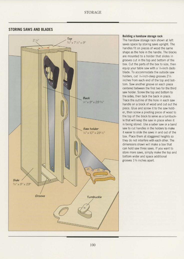
STORAGE
STORING SAWS AND BLADES
Building a handsaw storage rackThe handsaw storage rack shown at leftsaves space by storing saws upright. Thehandles fit on oieces of wood the sameshape as the hole in the handle. The blocksare mounted to a holder that s l ides ingrooves cut in the top and bottom of thebox. Cut the parts of the box to size, thenequip your table saw with a %-inch dadoblade. To accommodate the outside sawholders, cut %-inch-deep grooves 2%inches from each end of the top and bot-tom. Saw another groove on each piececentered between the first two for the thirdsaw holder. Screw the top and bottom tothe sides, then tack the back in place.Trace the out l ine of the hole in each sawhandle on a block of wood and cut out thepiece. Glue and screw i t to the saw hold-er, then screw a pivoting piece of wood tothe too of the block to serve as a turnbuck-le that will keep the saw in place when itis being stored. Use a saber saw or a bandsaw to cut handles in the holders to makeit easier to slide the saws in and out of thebox. Place them at staggered heights sothey do not interfere with each other. Thedimensions shown will make a box thatcan hold saw three saws. lf you want tostore more saws, simply make the top andbottom wider and space additionalgrooves 1% inches apart.
Baak1/+" x 9" x 29 3/+u
5aw holder1/+"x10"x291/2"
3 /+ "x8 "x29 "
Turnbuakle
/.J- /re
I00
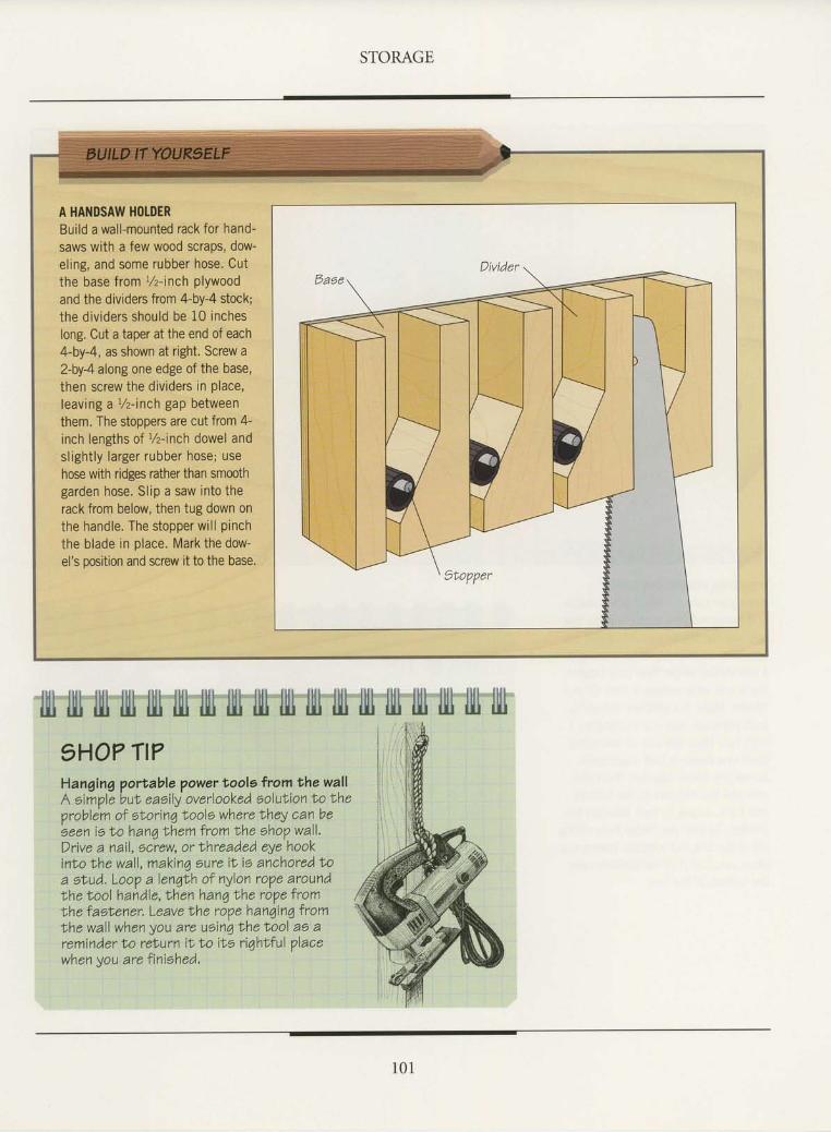
STORAGE
A HANDSAW HOTDERBuild a wall-mounted rack for hand-saws with a few wood scraps, dow-eling, and some rubber hose. Cutthe base trom r/z-inch plywoodand the dividers from 4-by-4 stock;the dividers should be 10 incheslong. Cut a taper at the end of each4-by-4, as shown at right. Screw a2-by4alongone edge of the base,then screw the dividers in place,leaving aVz-inch gap betweenthem. The stoppers are cut from 4-inch lengths of l/z-inch dowel andslightly larger rubber hose; usehose with ridges rather than smoothgarden hose. Slip a saw into therack from below, then tug down onthe handle. The stopper will pinchthe blade in place. Mark the dow-el's position and screw it to the base.
fiIl lllj lll lll lll] llll llll llll llll llll illl llll llll)HO? TI?Hanging portable ?ower toole from the wallA eim?le buV eaoily overlooked eolution to t'heproblem of elorinq Nools where lhey can beeeen ie No hang bhem from Nhe ohop wall.Drive a nail, ecrew, or lhreaded eye hookinto lhe wall, makinq sure iN is anchored f'oa elud. Loop a lenqlh of nylon rope aroundNhe tool handle,lhen han6 t'he rope fromIhe faslener, Leave t'he rope hanqinq fromLhe wall when you are uoinq t'he lool ae areminder No relurn it to it 'e riqhtful placewhen you are finiehed.
Illllttlllltlltllt
1 0 1
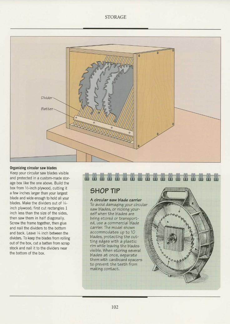
STORAGE
0rganizing circular saw bladesKeep your circular saw blades vis ibleand protected in a custom-made stor-age box l ike the one above. Bui ld thebox from t/z-inch plywood, cutting ita few inches larger than your largestblade and wide enough to hold all yourblades. Make the divrders out of t/q-inch plywood; f i rst cut rectangles 1inch less than the size of the sides,then saw them in ha l f d iagona l ly .Screw the frame together, then glueand nai l the dividers to the bottomand back. Leavel/q inch between thedividers. To keep the blades from rollingout of the box, cut a batten from scrapstock and nai l i t to the dividers nearthe bottom of the box.
lllt lllr lll iltl lllt lll1 tlll llt illl illl illt tlll ljlt rlll lllt tlll lltl llll9HO7 Tt?A aircular saw blade aarrierTo avoid damaqin4 your circulareaw blades, or nickin4 your-eelf when Lhe blades arebeinq otored or Nranoporl-ed, use a commercial bladecarrier. The model shownaccommodahee up to 10bladee, protecNinq the cuN-t inq edqee wiNh a plaoLicr im whi le leavinq Lhe bladeevieible. When eNorinq oeveralblades al once, oeparateNhem wilh cardboard 6?acerelo prevenl lhe Neeth frommakinq conlacN.
r02
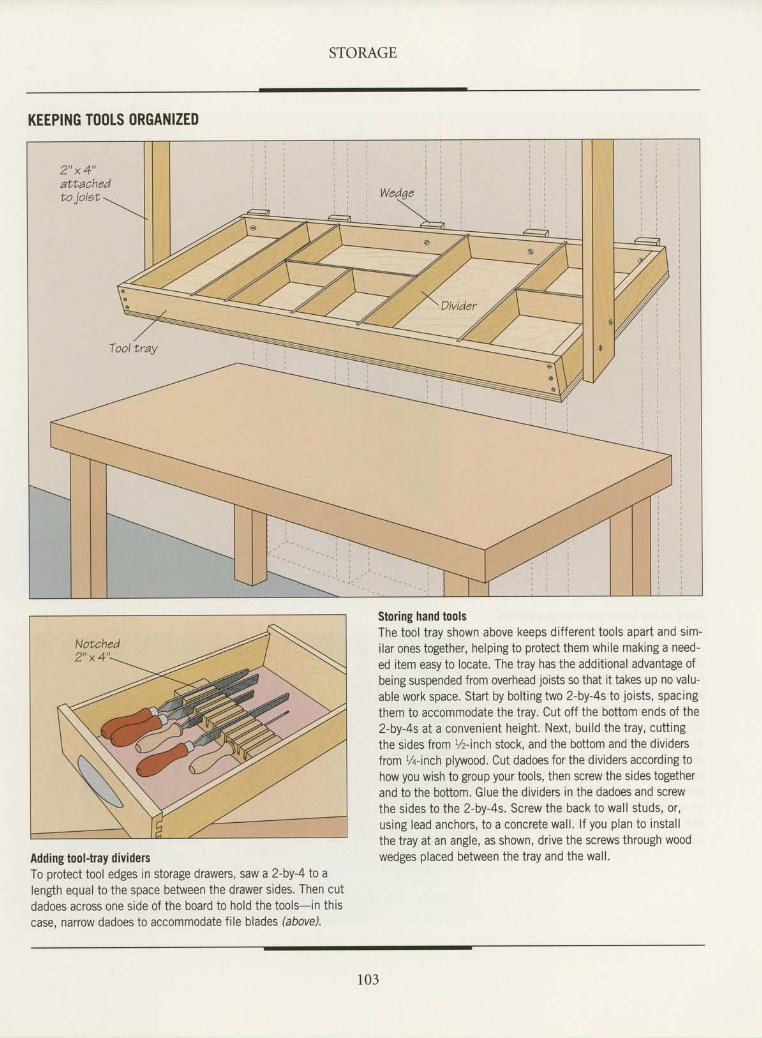
STORAGE
KEEPING TOOLS ORGANIZED
Adding tool-tray dividersTo protect tool edges in storage drawers, saw a 2-by-4 to alength equal to the space between the drawer sides. Then cutdadoes across one side of the board to hold the tools-in thiscase, narrow dadoes to accommodate file blades (above).
Storing hand toolsThe tool tray shown above keeps different tools apart and sim-ilar ones together, helping to protect them while making a need-ed item easy to locate. The tray has the additional advantage ofbeing suspended from overhead joists so that it takes up no valu-able work space. Start by bolting two 2-by-4s to joists, spacingthem to accommodate the tray. Cut off the bottom ends of theZ-by-4s at a convenient height. Next, build the tray, cuttingthe sides from %-inch stock, and the bottom and the dividersfrom 7+-inch plywood. Cut dadoes for the dividers according tohow you wish to group your tools, then screw the sides togetherand to the bottom. Glue the dividers tn the dadoes and screwthe sides to the 2-by-4s. Screw the back to wall studs, or,using lead anchors, to a concrete wall. lf you plan to installthe tray at an angle, as shown, drive the screws through woodwedges placed between the tray and the wall.
103
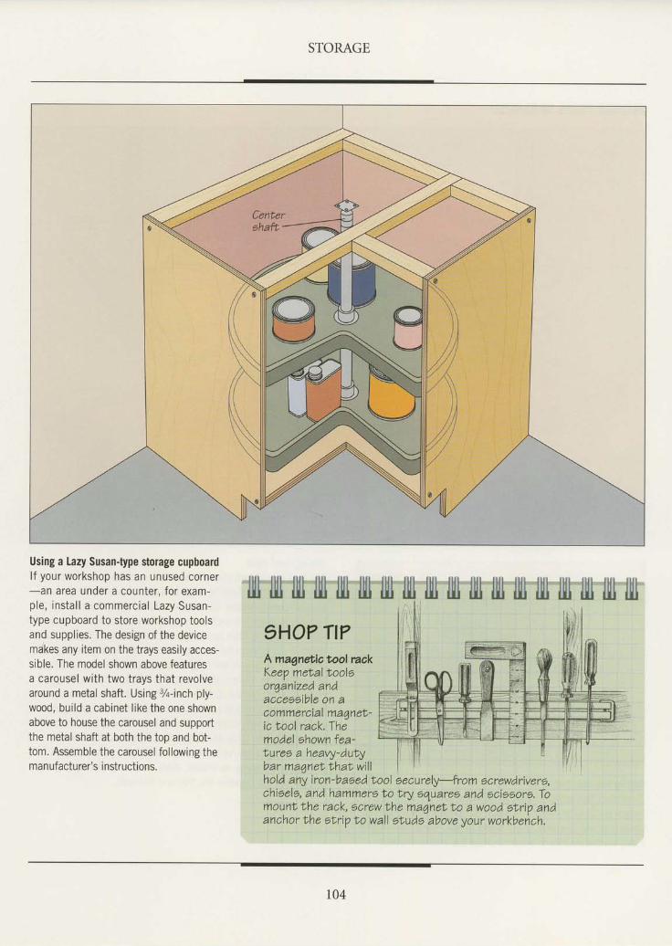
STORAGE
Using a Lazy Susan{ype storage cupboardl f your workshop has an unused corner-an area under a counter, for exam-ple, instal l a commercial Lazy Susan-type cupboard to store workshop toolsand supplies. The design of the devicemakes any item on the trays easily acces-sible. The model shown above featuresa carousel with two trays that revolvearound a metal shaft. Using %-inch ply-wood, build a cabinet like the one shownabove to house the carousel and supportthe metal shaft at both the too and bot-tom. Assemble the carousel following theman ufacturer's i nstructions.
flIl rll1 lllj llll ru llll llll illl fiIj fiIl fill lllj llll lll ljll ljll llll lllr1HO? Tt?Amagnetictool mckKeep melalNooloor4anized andaccessible on acommercial maqnel-ic Nool rack.Themodel shown fea-Eures a heavy-duLybar maqneNlhaLwi l lholA any iron-based lool eecurely-from screwdrivers,chieels, and hammero lo Lry equaree and ocieeors. Tomount f,he rack, screw Nhe maqneN lo a wood etrip andanchor Lhe otrip No wall e|uds above your workbehch,
t04
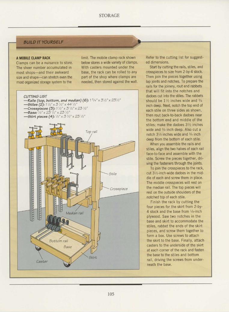
STORAGE
A MOBITE CLAMP RACKClamos can be a nuisance to store.The sheer number accumulated inmost shoos-and their awkwardsize and shape--can stretch even themost organized storage system to the
l imit . The mobi le clamp rack shownbelow stores a wide variety of clamps.With casters mounted under thebase, the rack can be rol led to anypart of the shop where clamps areneeded, then stored agatnst the wall,
Refer to the cutting list for suggest-ed dimensions.
Start by cutting the rails, stiles, andcrosspieces to size from 2-by-4 stock.Then join the pieces together usinglap joints and notches. To prepare therails for the joinery, rout end rabbetstha t w i l l f i t in to the no tches anddadoes cut into the stiles. The rabbetsshou ld be I1 /z inches w ide and 34
inch deep. Next, notch the top end ofeach st i le on three sides as shown,then rout back-to-back dadoes nearthe bo t tom end and midd le o f thest i les; make the dadoes 3% incheswide and 3/q inch deep. Also cut anolch 3t/z inches wide and 7q inchdeeo from the bottom of each stile.
When you assemble the rai ls andstiles, align the two halves of each railface-to-face and assemble with thestile. Screw the pieces together, dri-ving the fasteners through the joints,
To join the crosspieces to the rack,cut 3%-inch-wide dadoes in the mid-dle of each and screw them in place.The middle crosspieces wi l l rest onthe median rai l . The top pieces wi l lrest on the outside shoulders of thenotched top of each stile.
F in ish the rack by cu t t ing thefour pieces for the skir t f rom 2-by-4 stock and the base from l/rinch
plywood. Saw two notches in thebase and skir t to accommodate thestr les, rabbet the ends of the skir ipieces, and screw them together toform a box. Use screws to attachthe skir t to the base. Final ly, at tachcasters to the underside of the skir tat each corner of the rack and fasienthe base to the stiles and bottomrai l , dr iv ing the screws from under-neath the base.
CUTTINO LIST-Raile (top, bottom, and median) (6): t 3/+" x 31/'2" x 231/2"-gtilee (2): 1 / " x 3 / " x 44 / "
-Croaspiecea (3):11,/2" x 3t/2" x 23t/z-Eaeai/+" x 23 1/2" x 23'/2"-1kirt piecea (4):1/2" x 3t/2" x 23 i/2"
105
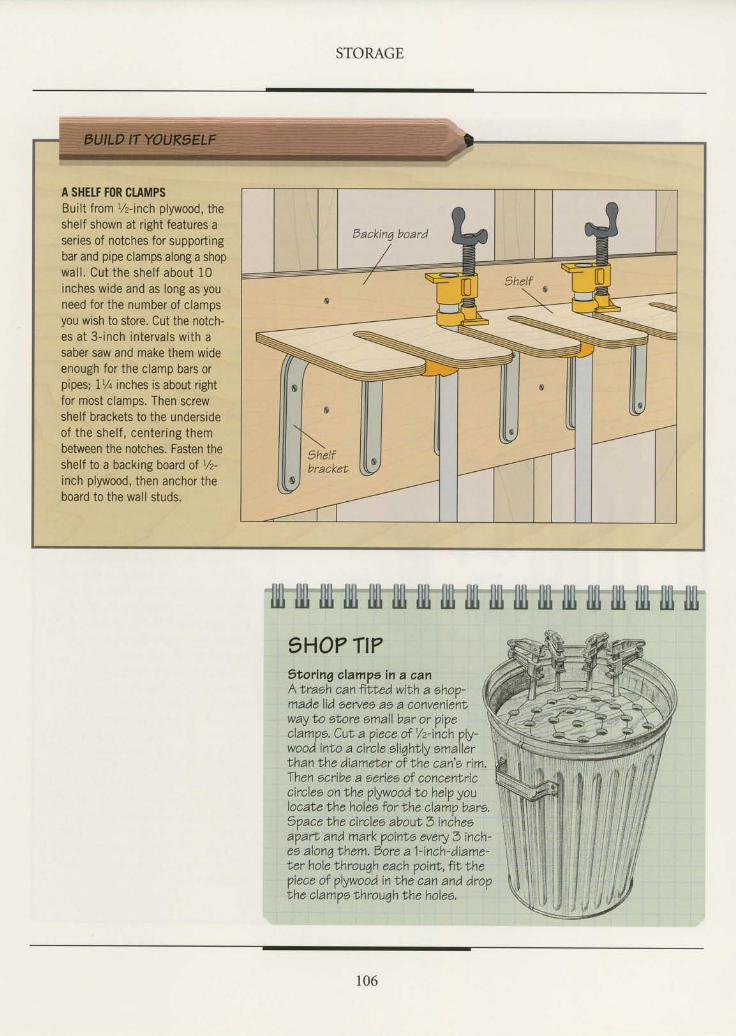
STORAGE
A SHETF FOR CTAMPSBuilt from l/z-inch plywood, theshelf shown at right features aseries of notches for supportingbar and pipe clamps along a shopwal l . Cut the shelf about 10inches wide and as long as youneed for the number of clampsyou wish to store. Cut the notch-es at 3- inch intervals with asaber saw and make them wideenough for the clamp bars orpipes; 17+ inches is about rightfor most clamos, Then screwshelf brackets to the undersideof the shelf , center ing thembetween the notches. Fasten theshelf to a backing board of Vz-inch plywood, then anchor theboard to the wall studs.
llll IIl llt'filt IIl tll'ffi IIl lll llll illt fit'IllilIt filt llll lltt tlll)HO? TI??toring alampe in a oanAtraeh canfilhedwith a ehoo-made lid eeryel as a conveniertlway to sLore small bar or pipeclampe. Cul a oiece of 1/z-inch plv-wooA into a ciicle oliqhtly emaiti,lhan the diameLer of lhe can'o rim.Then scribe a series of concenlriccircles on trhe plywood to help youlocale the holes for the clamp bare,1Vacetrhe circles aboutb incheeapart and mark poinLe every 3 inch-ee alonq lhem, Bore a f-inch- diame-ter hole throuqh each p oint, fit, thepiece of plywood in the can and dropthe clamos lhrouah lhe holes.
106
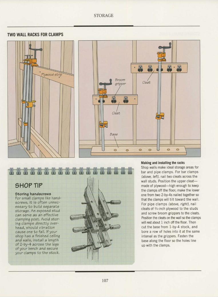
STORAGE
TWO WALI RACKS FOR CLAMPS
Making and installing the racksShop walls make ideal storage areas forbar and pipe clamps. For bar clamps(above, left), nail two cleats across thewall studs. Position the upper cleat-made of plywood-high enough to keepthe clamps off the floor; make the lowerone from two 2-by-4s nailed together sothat the clamps will ti lt toward the wall.For pipe clamps (above, right), nailcleats of 3/q-inch plywood to the studsand screw broom grippers to the cleats.Position the cleab on the wall so the clampswill rest about 1 inch off the floor. Thencut the base from 1-by-4 stock, andbore a row of holes into it at the sameinterval as the grippers. Fasten thebase along the floor so the holes lineup with the clamps.
t07
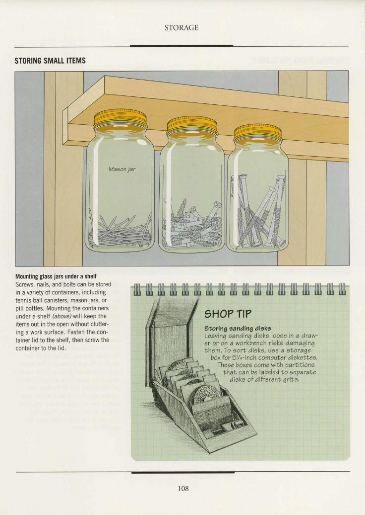
STORAGE
STORING SMALL ITEMS
Mounting glass jars under a shelfScrews, nails, and bolts can be storedin a variety of containers, includingtennis ball canisters, mason jars, orpill bottles. Mounting the containersunder a shelf (above) will keep theitems out in the ooen without clutter-ing a work surface. Fasten the con-tainer lid to the shelf. then screw thecontainer to the lid.
108
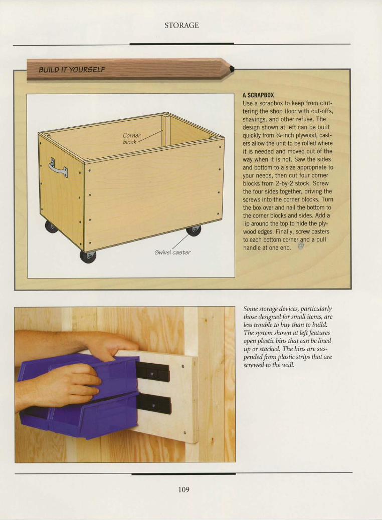
STORAGE
A SCRAPBOXUse a scrapbox to keep from clut-tering the shop floor with cut-offs,shavings, and other refuse. Thedesign shown at left can be builtquickly from %-inch plywood; cast-ers allow the unit to be rolled whereit is needed and moved out of theway when it is not. Saw the sidesand bottom to a size appropriate toyour needs, then cut four cornerblocks from 2-by-2 stock. Screwthe four sides together, driving thescrews into the corner blocks. Turnthe box over and nail the bottom tothe corner blocks and sides. Add alip around the top to hide the ply-wood edges. Finally, screw castersto each bottom corner qnd a pullhandle at one end. f'{'
Some storage devices, particularlythose designed for small items, areless trouble to buy than to build.The system shown at left featuresopen plastic bins that can be linedup or stacked. The bins are sus-pended from plastic strips that arescrewed to the wall.
109
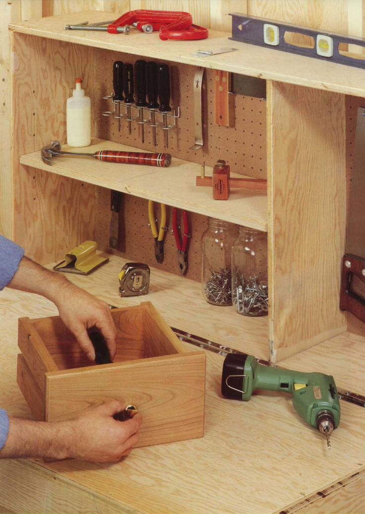
::}tu
-itffif"
n{;i4
w.:.| .::' 1l
a
r <at "-rr l. l
. :
lre,.*s
+.""{hi*.v'
Hb+
' - -*}*
qi3
.f,
"''airi+:r:,'Y,e-: ., _' ffiSdg**ffft
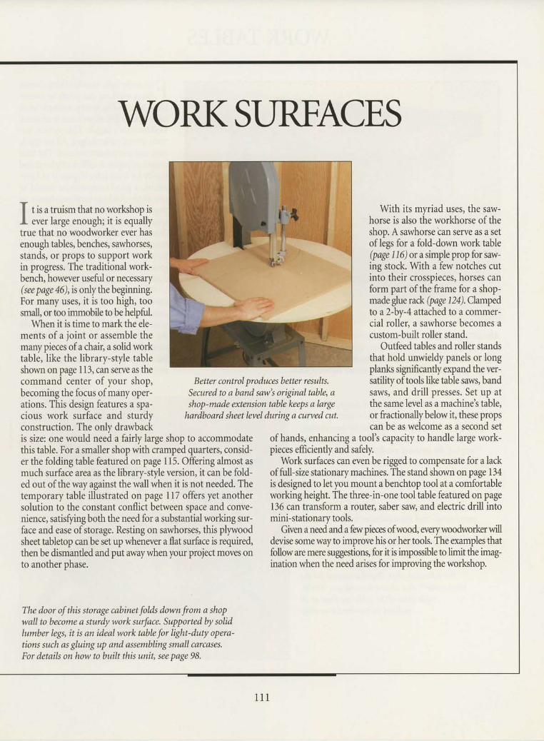
WORKSreS
f t is a truism that no worlshop isI ever large enough; it is equallytrue that no woodworker ever hasenough tables, benches, sawhorses,stands, or props to support workin progress. The traditional work-bench, however useful or necessary(supage 46),is onlythe beginning.For many uses, it is too high, toosmall, or too immobile to be helpfuL
When it is time to markthe ele-ments of a joint or assemble themany pieces of a chair, a solid worktable, like the library-style tableshown on page 113, can serve as thecommand center of your shop,becoming the focus of many oper-ations. This design features a spa-cious work surface and sturdyconstruction. The onlv drawbackis size: one would need a fairly large shop to accommodatethis table. For a smaller shop with cramped quarters, consid-er the folding table featured on page 115. Offering almost asmuch surface area as the library-style version, it can be fold-ed out of the way against the wall when it is not needed. Thetemporary table illustrated on page ll7 offers yet anothersolution to the constant conflict between space and conve-nience, satisfying both the need for a substantial working sur-face and ease of storage. Resting on sawhorses, this plywoodsheet tabletop can be set up whenever a flat surface is required,then be dismantled and put awaywhen your project moves onto another phase.
Better control produca better results,Secured to aband smr's original table, ashop-made extension table lceeps a large
hardboard sheetlevel duringa curved cut.
With its myriad uses, the saw-horse is also the workhorse of theshop. A sawhorse tan serve as a setof legs for a fold-down work table(page 116) or a simple prop for saw-ing stock. With a few notches cutinto their crosspieces, horses canform part of the frame for a shop-made glue rack (page Da).Clampedto a2-bv-4 attached to a commer-cial roller, a sawhorse becomes acustom-built roller stand.
Outfeed tables and roller standsthat hold unwieldy panels or longplanks significantly expand the ver-satility of tools like table saws, bandsaws, and drill presses. Set up atthe same level as a machine's table,or fractionallybelow it, these propscan be as welcome as a second set
of hands, enhancing a tool's capacity to handle large work-pieces efficiently and safely.
Work surfaces can even be rigged to compensate for a lackof firll-size stationary machines. The stand shown on page 134is designed to let you mount a benchtop tool at a comfortableworking height. The three-in-one tool table featured on page136 can transform a router, saber saw and electric drill intomini-stationary tools.
Given a need and a few pieces ofwood, werywoodworker willdevise somewayto improve his or her tools. The examples thatfolloware mere suggestions, for it is imposibleto limitthe imag-ination when the need arises for improving the worlshop.
The door of this storage cabinet folds down from a shopwall to become a sturdy work surface. Supported by solidlumber legs, it is an ideal work table for light-duty opera-tions such as gluingup and assembling small carcases.For details on how to built this unit, see page 98.
l 1 l
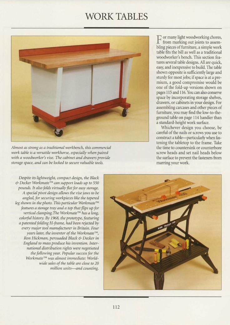
WORKTABLES
{",' or many light woodworking chores,l" frour rnarkins out ioints to asseln-bling pieces of furniture, a simple worktable fits the bill as well as a traditionalwoodworker's bench. This section fea-tures several table designs. All are quick,easy, and inexpensive to build. The tableshown opposite is sufficiently large andsturdy for nlost jobsi ifspace is at a pre-mium, a good compromise would beone of the fold-up versions shown onpages I 15 and I 16. You can also conservespace by incorporating storage shelves,drawers, or cabinets in your design. Forassembling carcases and other pieces offurniture. vou mav find the low-to-the-ground table on page 1 l4 handier thana standard-height work surface.
Whichever design you choose, becareful of the nails or screws you use toconstruct a table-particularly when fas-tening the tabletop to the frame. Thkethe time to countersink or counterborescrew heads and set nail heads belowthe surface to prevent the fasteners frommarring your work.
Alnrost as strong as a traditional workbench, this commercialwork table is a versatile workhorse, especially when pairedwith a woodworker's vise. The cabinet and drawers providestorage space, and can be locked to secLtre valuoble tools.
Despite its lightweight, conlpoct design, the Blackd* Decker Workntate'- can support loads up to 550
pounds. It oko folds virtually Jlat for easy storage.A special pivot design allows the vise jaws to betmgled, for sectn"ing workpieces like the tapered
Ieg shown in the photo. This particular Workmate'''
features a storage tray and a top that Jlips up forvertical clamping.The WorkntatetM has a long,
colorfulhistory. By 1968, the prototype, featuringa patented folding H-frante, had been rejected by
every major tool manufacturer in Britain. Fouryears later, the inventor of the Workmate'*,
Ron Hickmon, persuaded Black 6 Decker inEngland to mass produce his invention. Inter-
national distribution rights were negotiatedthe following year. Popular success for the
Worknnte'n' was olntost inmrcdiate: World-wide sales of the table are close to 20
milli o n un it s-an d c o un tin g.
rt2
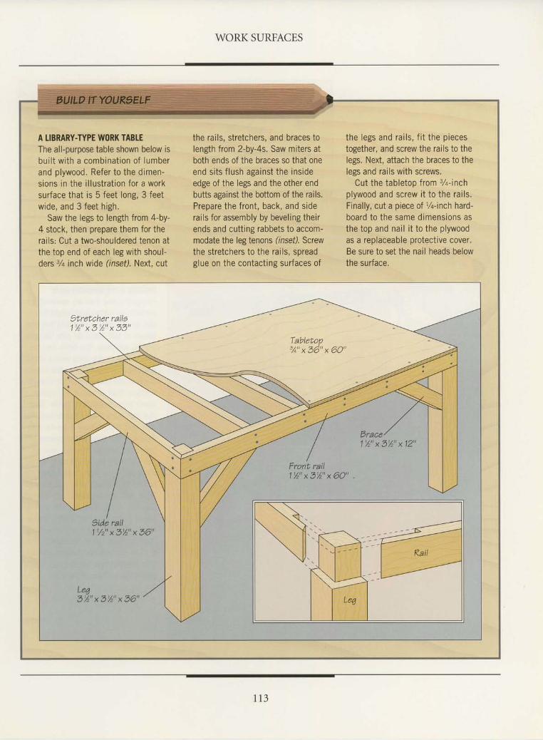
WORK SURFACES
A LIBRARY-TYPE WORK TABLEThe all-purpose table shown below isbui l t with a combinat ion of lumberand plywood. Refer to the dimen-sions in the i l lusirat ion for a worksurface that is 5 feet long, 3 feetwide, and 3 feet high.
Saw the legs to length from 4-by-4 stock, then prepare them for therails: Cut a two-shouldered tenon atthe top end of each leg with shoul-ders 3/a inch wide (inset). Next, cut
the rails, stretchers, and braces tolength from 2-by-4s. Saw miters atboth ends of the braces so that oneend si ts f lush against the insideedge of the legs and the other endbutts against the bottom of the rails.Prepare the front, back, and siderails for assembly by beveling theirends and cutting rabbets to accom-modate the leg tenons (insef). Screwthe stretchers to the rails, spreadglue on the contact ing surfaces of
the legs and rai ls, f i t the piecestogether, and screw the rails to thelegs. Next, attach the braces to thelegs and rails with screws.
Cut the tabletoo from 3Z-inchplywood and screw i t to the rai ls.Finally, cut a piece of %-inch hard-board to the same dimensions asthe top and nail it to the plywoodas a replaceable protective cover.Be sure to set the nail heads belowthe surface.
Tabletop% " x 3 6 " x 6 0 "
Brace'l %" x 5%" x 12"
Front rail'l %" x 3%" x 60"
9ide rail11 /2 "x3%"x36"
Leo3 % " x 5 % " x 3 6 "
1 1 3
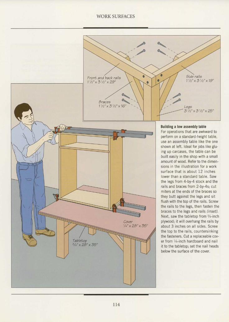
WORK SURFACES
Front and back raila11 /2 "x51 /2 "x29 "
. , / % \Erales %
- -1 1/2" x 31/2" x
'16"
Side rails11/2" x 31/2" x '19"
3 1 / 2 " x 3 1 / 2 " x 2 5 "
Building a low assembly tableFor operations that are awkward toperform on a standard-height table,use an assembly table l ike the oneshown at lef t . ldeal for jobs l ike glu-ing up carcases, the table can bebui l t easi ly in the shop with a smal lamount of wood. Refer to the dimen-sions in the i l lustrat ion for a worksur face tha t i s about 12 incheslower than a s tandard tab le . Sawthe legs from 4-by-4 stock and therai ls and braces from 2-by-4s; cutmiters at the ends of the braces sothey butt against the legs and si tflush with the too of the rails. Screwthe rai ls to the legs, then fasten thebraces to the legs and rails (inset).Next, saw the tabletop from %-inchplywood; i t wi l l overhang the rai ls byabout 3 inches on al l s ides. Screwthe top to the rai ls, countersinkingthe fasteners. Cut a replaceable cov-er from r/q-inch hardboard and naili t to the tabletop; set the nai l headsbelow the surface of the cover.
I I4
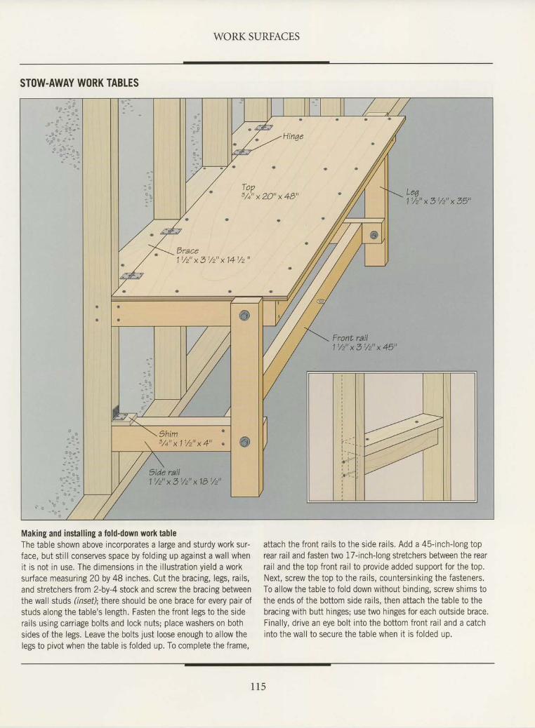
WORK SURFACES
STOW.AWAY WORK TABLES
Making and installing a fold-down work tableThe table shown above incorporates a large and sturdy work sur-face, but still conserves space by folding up against a wall whenit is not in use. The dimensions in the illustration yield a worksurface measuring 20 by 48 inches. Cut the bracing, legs, rails,and stretchers from 2-by-4 stock and screw the bracing betweenthe wall studs (insef); there should be one brace for every pair ofstuds along the table's length. Fasten the front legs to the siderails using carriage bolts and lock nuts; place washers on bothsides of the legs. Leave the bolts just loose enough to allow thelegs to pivot when the table is folded up. To complete the frame,
attach the front rails to the side rails. Add a 45-inch-long toprear rail and fasten two l7-inch-long stretchers between the rearrail and the top front rail to provide added support for the top.Next, screw the top to the rails, countersinking the fasteners.To allow the table to fold down without binding, screw shims tothe ends of the bottom side rails, then attach the table to thebracing with butt hinges; use two hinges for each outside brace,Finally, drive an eye bolt into the bottom front rail and a catchinto the wall to secure the table when it is folded up.
1 1 5
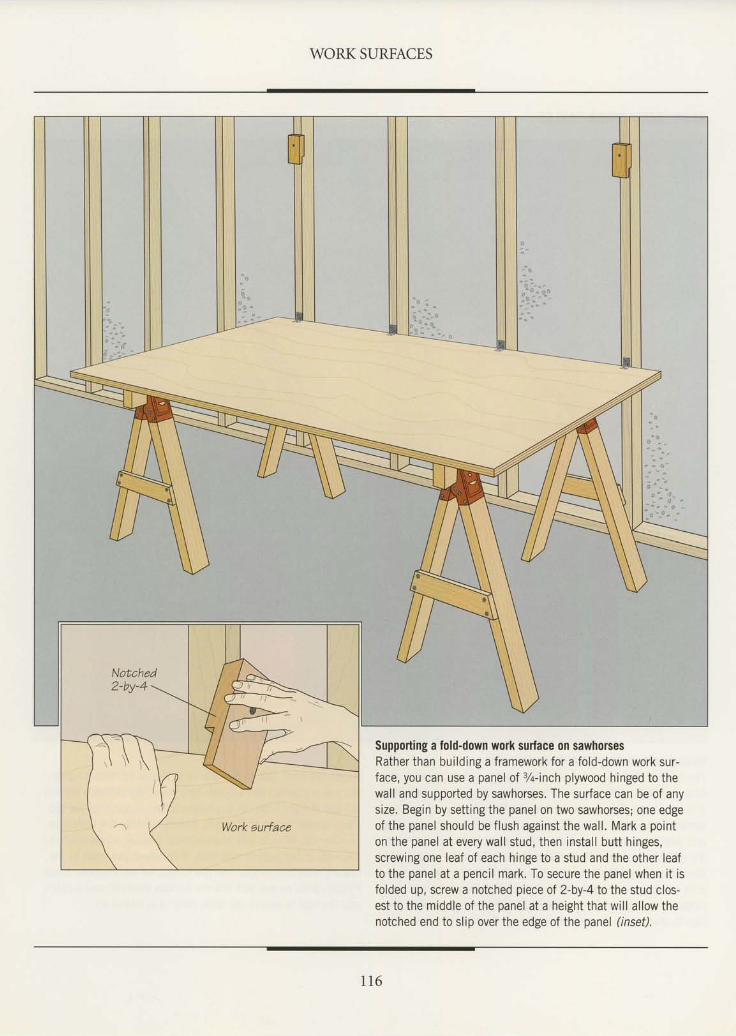
WORK SURFACES
Suppoiling a fold-down work surface on sawhorsesRather than building a framework for a fold-down work sur-face, you can use a panel of %-inch plywood hinged to thewall and supported by sawhorses. The surface can be of anysize. Begin by setting the panel on two sawhorses; one edgeof the panel should be flush against the wall. Mark a pointon the panel at every wall stud, then install butt hinges,screwing one leaf of each hinge to a stud and the other leafto the panel at a pencil mark. To secure the panel when it isfolded up, screw a notched piece of 2-by-4to the stud clos-est to the middle of the panel at a height that will allow thenotched end to slip over the edge of the panel (inset).
1 1 6
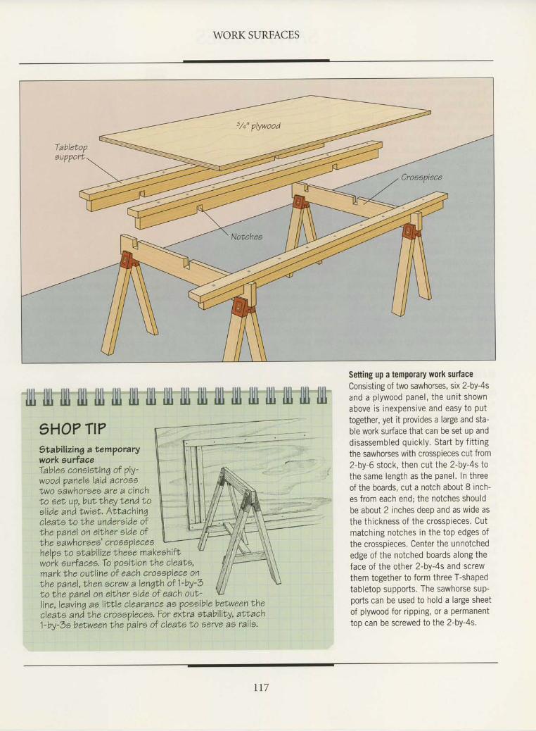
WORK SURFACES
Setting up a temporary wolk surfaceConsisting of two sawhorses, six 2-by-4sand a plywood panel, the unit shownabove is inexpensive and easy to puttogether, yet it provtdes a large and sta-ble work surface that can be set up anddisassembled quickly. Start by fittingthe sawhorses with crosspieces cut from2-by-6 stock, then cut the 2-by-4s tothe same length as the panel. In threeof the boards, cut a notch about 8 inch-es from each end; the notches shouldbe about 2 inches deep and as wide asthe thickness of the crosspieces. Cutmatching notches in the top edges ofthe crosspieces. Center the unnotchededge of the notched boards along theface of the other 2-by-4s and screwthem together to form three T-shapedtabletop supports. The sawhorse sup-ports can be used to hold a large sheetof plywood for ripping, or a permanenttop can be screwed to the 2-by-4s.
rt7
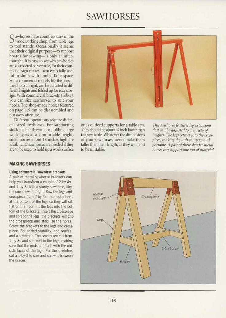
SAWHORSES
Q awhorses have countless uses in therJ woodworking shop, from table legsto tool stands. Occasionally it seemsthat their original purpose-to supportboards for sawing-is only an after-thought. It is easy to see why sawhorsesare considered so versatile, for their com-pact design makes them especially use-ful in shops with limited floor space.Some commercial models, like the ones inthe photo at right, can be adjusted to dif-ferent heights and folded up for easy stor-age. Wth commercial brackets (.below),you can slze sawnorses to sult yourneeds. The shon-made horses featuredon page 119 can be disassembled andput away after use.
Different operations require differ-ent-sized sawhorses. For supportingstock for handsawing or holding largeworkpieces at a comfortable height,smallhorses about 18 inches hieh areideal. Taller sawhorses are neededif theyare to be used to hold up a work surface
MAKING SAWHORSES
Using commercial sawhorse bracketsA pair of metal sawhorse brackets canhelp you transform a couple of 2-by-4sand 1-by-3s into a sturdy sawhorse, likethe one shown at right. Saw the legs andcrosspiece from 2-by-4s, then cut a bevelat the bottom of the legs so they will sitflat on the floor. Fit the legs into the bot-tom of the brackets, insert the crosspieceand spread the legs; the brackets will gripthe c rossp iece and s tab i l i ze the horse .Screw the brackets to the legs and cross-piece. For added stabi l i ty, add bracesand a stretcher. The braces are cut from1-by-3s and screwed to the legs, makingsure that the ends are f lush with the out-side faces of the legs. For the stretcher,cut a 1-by-3 to size and screw it betweenthe braces.
or as outfeed supports for a table sawThey should be about % inch lower thanthe saw table. Whatever the dimensionsof your sawhorses, never make themtaller than their length, as they will tendto be unstable.
This sawhorse features leg extensionsthat can be adjusted to a variety ofheights. The legs retract into the cross-piece, making the unit compact andportable. A pair of these slender metalhorses can support one ton of material.
1 1 8
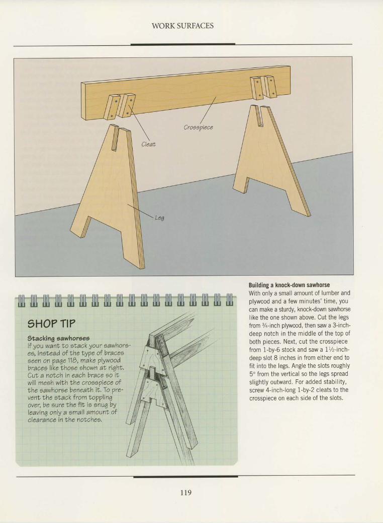
WORK SURFACES
Building a knock-down sawhorseWith only a small amount of lumber andplywood and a few minutes' time, youcan make a sturdy, knock-down sawhorselike the one shown above. Cut the legsfrom 7+inch plywood, then saw a 3-inch-deep notch in the middle of the top ofboth pieces. Next, cut the crosspiecefrom 1-by-6 stock and saw a 1%-inch-deep slot 8 inches in from either end tofit into the legs. Angle the slots roughly5o from the vertical so the legs spreadslightly outward. For added stability,screw 4-inch-long 1-by-2 cleats to thecrossoiece on each side of the slots.
1 1 9
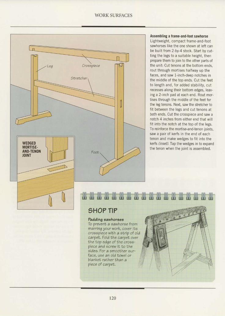
WORK SURFACES
Assembling a frame-and-foot sawhorseLightweight, com pact f rame-and-footsawhorses like the one shown at left canbe built from 2-by-4 stock. Start by cut-t ing the legs to a sui table height, thenprepare them to join to the other parts ofthe unit: Cut tenons at the bottom ends,rout through mort ises halfway up thefaces, and saw l- inch-deep notches inthe middle of the top ends. Cut the feetto length and, for added stabi l i ty, cutrecesses along their bottom edges, Ieav-ing a 2- inch pad at each end. Rout mor-tises through the middle of the feet forthe leg tenons. Next, saw the stretcher tof i t between the legs and cut tenons atboth ends. Cut the crosspiece and saw anotch 4 inches from either end that wi l lfit into the notch at the top of the legs.To reinforce the mortise-and-tenon joints,saw a pair of kerfs in the end of eachtenon and make wedges to f i t into thekerts (inset). Tap the wedges in to expandthe tenon when the joint is assembled.
I]ll ilI] illr fitl illt illt llll lllt fitl
?adding sawhorsesTo prevenl a sawhorse frommarrinq your work, cover ilscroeeViece wilh a ebrip of oldcarpeN. Fold the caroet overtheNop edqe of lhe cross-piece and ocrew it,to theeidee. For a smoolher our-face, use an oldNowel orblanket,ralherthan a i. ^ r ^ ^ ^ - c ipiece of car?et.
WEDGEDMORTISE-A1{D-TENONJOINT
uu llillll9HO?
illlllltTI?
lllli l t lilt lltllilui lll
r20
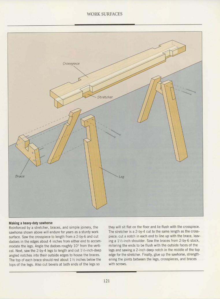
WORK SURFACES
Making a heavy-duty sawhorseReinforced by a stretcher, braces, and simple joinery, thesawhorse shown above will endure for years as a sturdy worksurface. Saw the crosspiece to length from a2-by-6 and cutdadoes in the edges about 4 inches from either end to accom-modate the legs. Angle the dadoes roughly LOo from the verti-cal. Next, saw the 2-by-4 legs to length and cut 1%-inch-deepangled notches into their outside edges to house the braces.The top of each brace should rest about 1% inches belowthetops of the legs. Also cut bevels at both ends of the legs so
they will sit flat on the floor and lie flush with the crosspiece.The stretcher is a 2-by-4 cut to the same length as the cross-piece; cut a notch in each end to line up with the brace, leav-inga lL/z-inch shoulder. Saw the braces from 2-by-6 stock,mrtering the ends to be flush with the outside faces of thelegs and sawing a 2-inch deep notch in the middle of the topedge for the stretcher. Finally, glue up the sawhorse, strength-ening the joints between the legs, crosspieces, and braceswith screws.
r2r
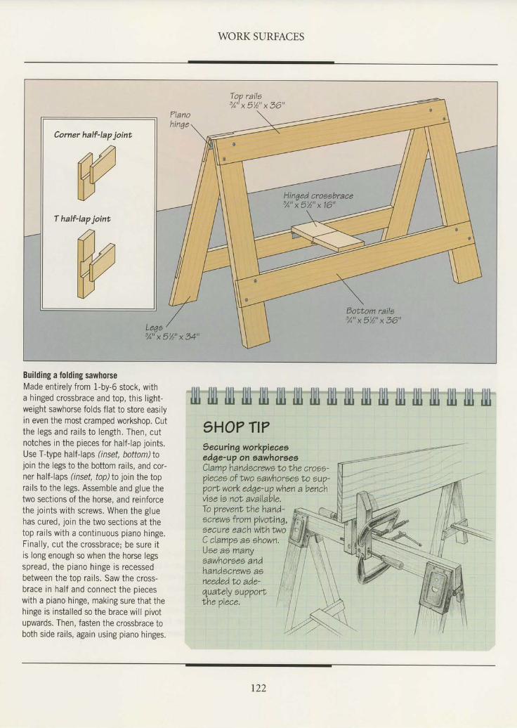
WORK SURFACES
Top railo3 /o "x5%"x36"
Corner half-lap joint
(flW
half-lap joint.
aIWa\)
3A"x5%"x54"
Hinged cro66brace3 / ^ "x5%"x16"
Building a folding sawhorseMade entirely from 1-by-6 stock, witha hinged crossbrace and top, this light-weight sawhorse folds flat to store easilyin even the most cramped workshop. Cutthe legs and rai ls to length. Then, cutnotches in the pieces for half-lap joints.Use Ttype half-laps (inset, bottom)tojoin the legs to the bottom rails, and cor-ner half-laps (inset, top) to join the toprai ls to the legs. Assemble and glue thetwo sections of the horse, and reinforcethe joints with screws. When the gluehas cured, join the two sect ions at thetop rai ls with a cont inuous piano hinge.Final ly, cut the crossbrace; be sure i tis long enough so when the horse legsspread, the piano hinge is recessedbetween the top rails. Saw the cross-brace in half and connect the pieceswith a piano hinge, making sure that thehinge is installed so the brace will pivotupwards. Then, fasten the crossbrace toboth side rai ls, again using piano hinges.
1HO? TI?Seouring workpieaeoedge-up on sawhorsesClamp handscrewe ln lhe croee-piecee of Iwo sawhoreee to eup-port work edqe-up when a benchvise ie not, available.
l]ll lll1 tll] tlll tlll tlll llltr fiu lll1 filt fit] llll lll1 llll ll11 lltl filJ iill
To prevenl lhehand-screwl from pivoNinq,aecure each withlwoC clampe as shown.Uoe ao manysawhorses andhandscrews asneededNo ade-quabe,ly 6u??ort ITne ?ECe, I I^
r22
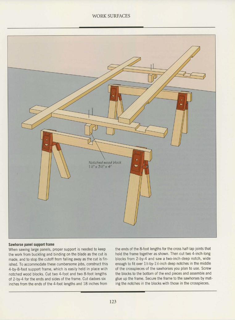
WORK SURFACES
Notched wood block1 % " x 3 % " x 4 "
Sawhorse panel support frameWhen sawing large panels, proper support is needed to keepthe work from buckl ing and binding on the blade as the cut ismade, and to stop the cutoff from falling away as the cut is fin-ished. To accommodate these cumbersome jobs, construct this4-by-8-foot support f rame, which is easi ly held in place withnotched wood blocks. Cut two 4-foot and two 8-foot lengthsof 2-by-4 for the ends and sides of the frame. Cut dadoes sixinches from the ends of the 4joot lensths and 18 inches from
the ends of the S{oot lengths for the cross half-lap joints thathold the frame together as shown. Then cut two 4-inch-longblocks from 2-by-4 and saw a two-inch-deep notch, wideenough to fit over 7%-by-I%-inch deep notches in the middleof the crosspieces of the sawhorses you plan to use. Screwthe blocks to the bottom of the end pieces and assemble andglue up the frame. Secure the frame to the sawhorses by mat-ing the notches in the blocks with those in the crosspieces.
r23
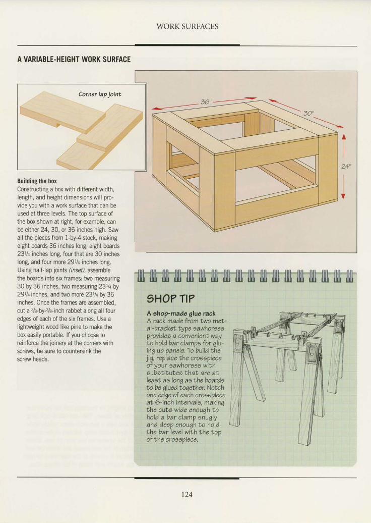
WORK SURFACES
A VARIABLE.HEIGHT WORK SURFACE
Building the boxConstructing a box with different width,lengh, and height dimensions will pro-vide you with a work surface that can beused at three levels. The too surface ofthe box shown at right, for example, canbe either 24,30, or 36 inches high. Sawall the pieces from 1-by-4 stock, makingeight boards 36 inches long, eight boards23tla inches long, four that are 30 incheslong, and four more 29tl+ inches long.Using half-lap joints (lnset) assemblethe boards into six frames: two measuring30 by 36 inches, two measuring 23Ll+ by29tlq inches, and two more 23% by 36inches. Once the frames are assembled,cut a s/e-by-3/e-inch rabbet along all fouredges of each of the six frames. Use alightweight wood like pine to make thebox easily portable. lf you choose toreinforce the joinery at the corners withscrews, be sure to countersink thescrew heads.
24"
IIt
?HO? TI?A ehop-made glue raakA rack made from two mef,-al-bracket typ e eawhoreeeVrovideo a coinvenienN wayto hold bar clampo for qlu-inq up panele.To bui ldlheji6, replace ihe crooepieceof your sawhorses wilhoubstitutea thal are atleaet ao lonq ao lhe boardst'o be 6lued t o6ether. Notchone ed6e of each crooopieceat, 6-inch inlerv alo, m Akinqbhe cuts wide enouqhtohold a bar clamp enu6lyand deep enou7hlo holdthe barlevel with the topof t'he croeepiece.
r24
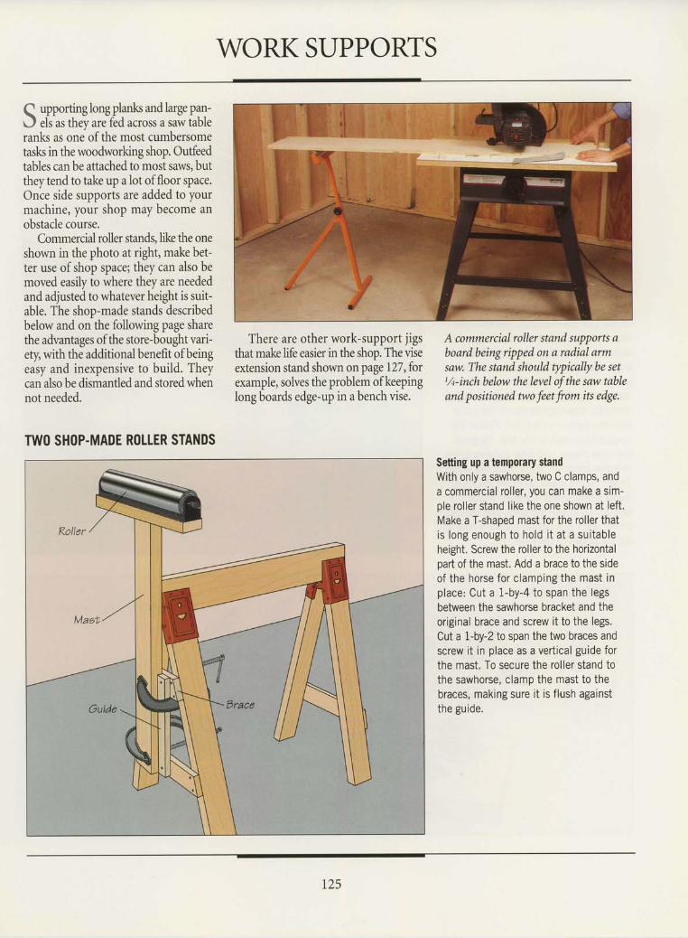
WORK SUPPORTS
Q upporling long plank and large pan-J els as thev are fed across a saw tableranks as one of the most cumbersometasls in the woodworking shop, Outfeedtables can be attached to most saws, butthey tend to take up a lot offloor space.Once side supports are added to yourmachine, your shop may become anobstacle course.
Commercial roller stands, like the oneshown in the photo at right, make bet-ter use of shop space; they can also bemoved easily to where they are neededand adjusted to whatever height is suit-able. The shop-made stands describedbelow and orthe following page sharethe advantages ofthe store-bought vari-ety, with the additional benefit of beingeasy and inexpensive to build. Theycan also be dismantled and stored whennot needed.
There are other work-support jigsthat make life easier in the shop. The viseextension stand shown on page 127, forexample, solves the problem of keepinglong boards edge-up in a bench vise.
A commercial roller stand supports aboard being ripped on a radial armsaw. The stand should typically be setl,/t-inch below the level of the saw tableand positioned two feet from its edge.
TW() SHOP.MADE ROLLER STANDSSetting up a temporary standWith only a sawhorse, two C clamps, anda commercial rol ler, you can make a sim-ple roller stand like the one shown at left.Make a T-shaped mast for the roller thatis long enough to ho ld i t a t a su i tab leheight. Screw the roller to the horizontalpart of the mast. Add a brace to the sideof the horse for c lamping the mast inplace: Cut a I-by-4 to span the legsbetween the sawhorse bracket and theoriginal brace and screw it to the legs.Cut a 1-by-2 to span the two braces andscrew i t in place as a vert ical guide forthe mast. To secure the roller stand tothe sawhorse, clamp the mast to thebraces, making sure i t is f lush againstthe guide.
r25
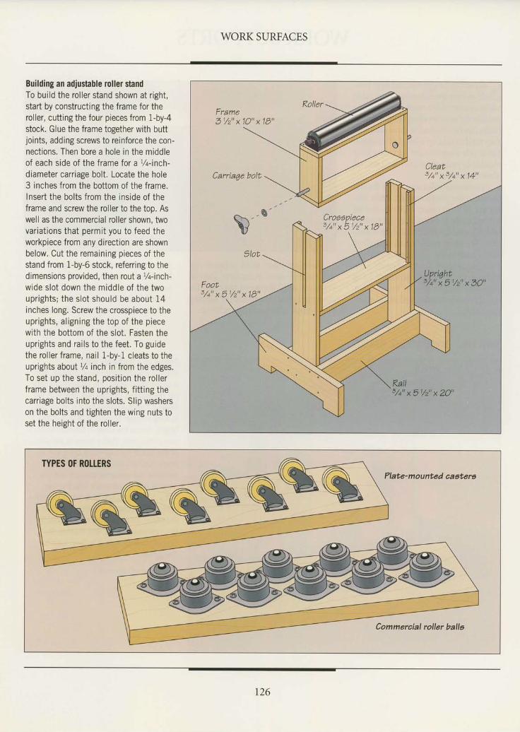
WORK SURFACES
Building an adjustable roller standTo build the roller stand shown at right,start by constructing the frame for theroller, cutting the four pieces from 1-by-4stock. Glue the frame together with buttjoints, adding screws to reinforce the con-nect ions. Then bore a hole in the middleof each side of the frame for a t/t-inch-
diameter carriage bolt. Locate the hole3 inches from the bottom of the frame.Insert the bolts from the inside of theframe and screw the roller to the too. Aswell as the commercial roller shown, twovariat ions that permit you to feed theworkpiece from any direction are shownbelow. Cut the remaining pieces of thestand from 1-by-6 stock, referring to thedimensions provided, then rout ar/q-inch-wide slot down the middle of the twouprights; the slot should be about 14inches long. Screw the crosspiece to theuprights, al igning the top of the piecewith the bottom of the slot. Fasten theuprights and rai ls to the feet. To guidethe rol ler f rame, nai l 1-by-1 cleats to theuprights aboull/q inch in from the edges.To set up the stand, posi t ion the rol lerframe between the uprights, f i t t ing thecarriage bolts into the slots. Slip washerson the bolts and tighten the wing nuts toset the heisht of the roller.
Plate-mounted aaatere
/ ^ rnaan iera
3 / + " x 5 1 / z " x 1 9 "
t26
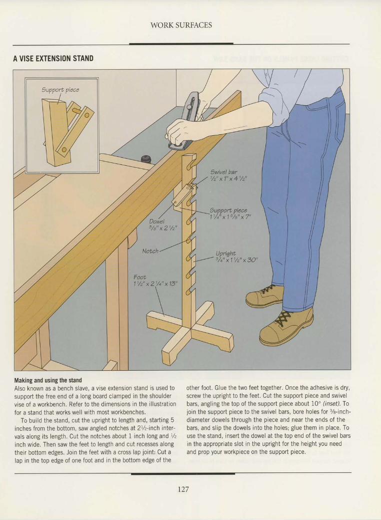
WORK SURFACES
A VISE EXTENSIOI{ STAND
Making and using the standAlso known as a bench slave, a vise extension stand is used tosupport the free end of a long board clamped in the shouldervise of a workbench, Refer to the dimensions in the illustrationfor a stand that works well with most workbenches.
To build the stand, cut the upright to length and, starting 5inches from the bottom, saw angled notches at2L/z-inch inler-vals along its length. Cut the notches about 1 inch long and r/z
inch wide. Then saw the feet to length and cut recesses alongtheir bottom edges. Join the feet with a cross lap joint: Cut alap in the top edge of one foot and in the bottom edge of the
other foot. Glue the two feet together. Once the adhesive is dry,screw the upright to the feet. Cut the support piece and swivelbars, angling the top of the support piece about 10" (inset). Tojoin the support piece to the swivel bars, bore holes for %-inch-diameter dowels through the piece and near the ends of thebars, and slip the dowels into the holes; glue them in place. Touse the stand, insert the dowel at the top end of the swivel barsin the appropriate slot in the upright for the height you needand prop your workpiece on the support piece.
t27
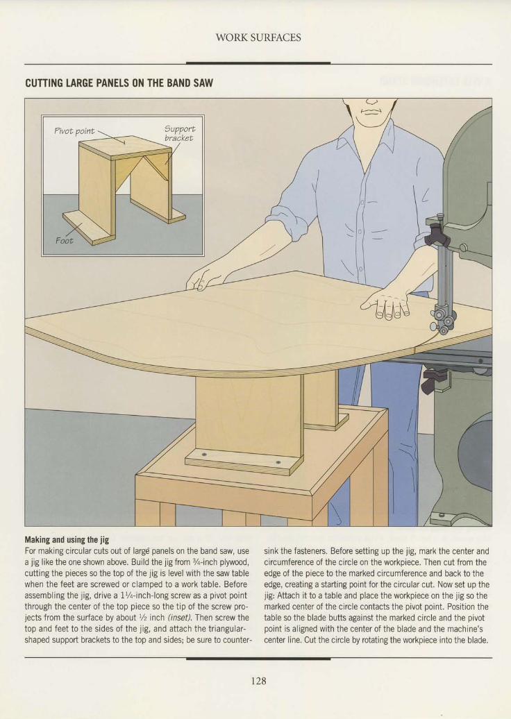
WORK SURFACES
CUTTING LARGE PANELS (lN THE BAND SAW
Making and using the jigFor making circular cuts out of large panels on the band saw, usea jig like the one shown above. Build the jig from 3/q-inch plywood,cutting the pieces so the top of the jig is level with the saw tablewhen the feet are screwed or clamped to a work table. Beforeassembling the jig, drive a IV+-inch-long screw as a pivot pointthrough the center of the top piece so the tip of the screw pro-jects from the surface by about Vz inch (inset). Then screw thetop and feet to the sides of the jig, and attach the triangular-shaped support brackets to the top and sides; be sure to counter-
sink the fasteners. Before setting up the jig, mark the center andcircumference of the circle on the workpiece. Then cut from theedge of the piece to the marked circumference and back to theedge, creating a starting point for the circular cut, Now set up thejig: Attach it to a table and place the workpiece on the jig so themarked center of the circle contacts the pivot point. Position thetable so the blade butts against the marked circle and the pivotpoint is aligned with the center of the blade and the machine'scenter line. Cut the circle by rotating the workpiece into the blade.
t28
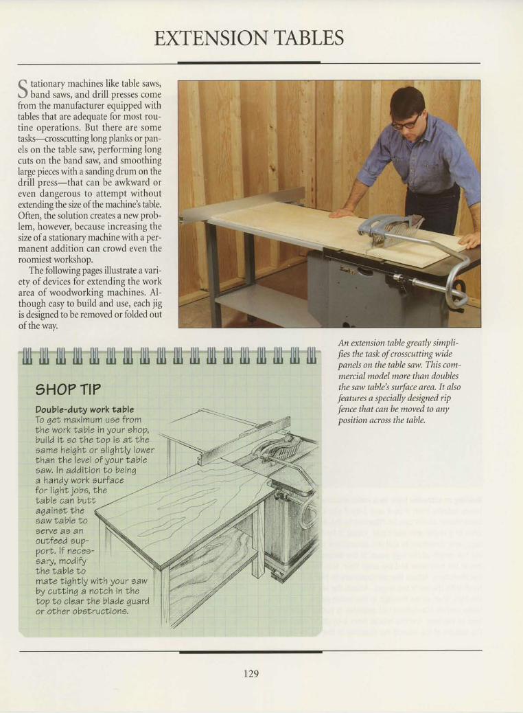
EXTENSION TABLES
Q tationary machines like table saws,J band saws, and drill presses comefrom the manufacturer equipped withtables that are adequate for most rou-tine ooerations. But there are sometasls-crosscutting long planls or pan-els on the table saw, performing longcuts on the band saw, and smoothinglarge pieces with a sanding drum on thedrill press-that can be awkward oreven dangerous to attempt withoutextending the size of the machine's table.Often, the solution creates a new prob-lem, however, because increasing thesize of a stationary machine with a per-manent addition can crowd even theroomiest workshop.
The following pages illustrate a vari-ety of devices for extending the workarea of woodworking machines. Al-though easy to build and use, each jigis designed to be removed or folded outof the way.
An extension table greatly simpli-
fies the task of crosscuttingwidepanels on the table saw. This com-mercial model more than doublesthe saw table's surface area. It also
features a specially designed rip
fence that can be moved to anyposition across the table.
1HO? TI?Double-duty workNableTo qet maximum uee fromlhe worktable in your ohop,bui ld i t oo the too ie al theoame heiqht, or eli7hr,ly lowerthan lhe level of your tableoaw.ln additr ion bo beinqa handy work eufiacetor light jobo, thelable can buttagainot thesaw lable toeerve a5 anoutfeed oup'port. l f neaee'oary, modifythe iable tomale liqhtly with you? eawby cutlinq a nolch in thetop to clear the blade 7uardo r' oth er ob sl,r u cIi o n s.
r29
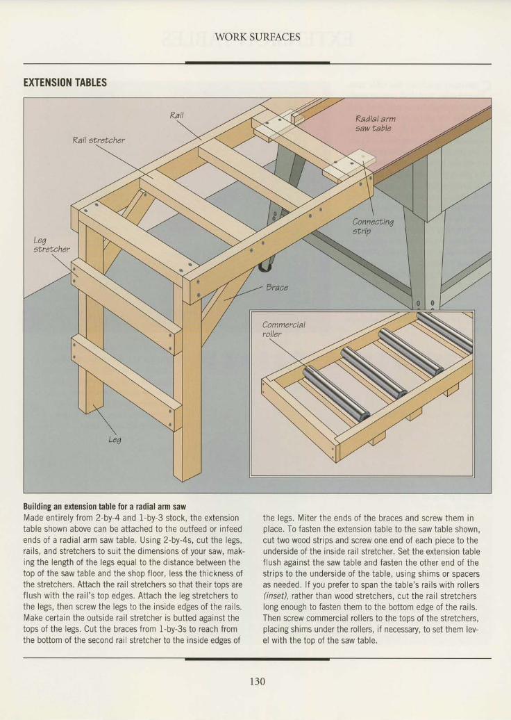
WORK SURFACES
EXTENSION TABTES
Building an extension table for a radial arm sawMade entirely from 2-by-4 and 1-by-3 stock, the extensiontable shown above can be attached to the outfeed or infeedends of a radial arm saw table. Using 2-by-4s, cut the legs,rails, and stretchers to suit the dimensions of your saw, mak-ing the length of the legs equal to the distance between thetop of the saw table and the shop floor, less the thickness ofthe stretchers. Attach the rail stretchers so that their tops areflush with the rail 's top edges. Attach the leg stretchers tothe legs, then screw the legs to the inside edges of the rails.Make certain the outside rail stretcher is butted against thetops of the legs. Cut the braces from 1-by-3s to reach fromthe bottom of the second rail stretcher to the inside edges of
the legs, Miter the ends of the braces and screw them inplace. To fasten the extension table to the saw table shown,cut two wood strips and screw one end of each piece to theunderside of the inside rail stretcher, Set the extension tableflush against the saw table and fasten the other end of thestrips to the underside of the table, using shims or spacersas needed. lf you prefer to span the table's rails with rollers(inset), rather than wood stretchers, cut the rail stretcherslong enough to fasten them to the bottom edge of the rails.Then screw commercial rollers to the tops of the stretchers,placing shims under the rollers, if necessary, to set them lev-el with the too of the saw table.
130
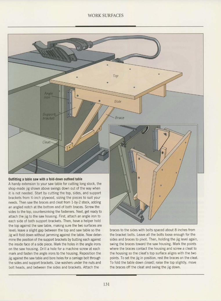
WORK SURFACES
outfitt ing a table saw with a fold-down outfeed tableA handy extension to your saw table for cut t ing long stock, theshop-made j ig shown above swings down out of the way wheni t is not needed. Star t by cut t ing the top, s ides, and supportbrackets f rom %-inch p lywood, s iz ing the p ieces to sui t your
needs. Then saw the braces and cleat from 1-by-2 stock, addingan angled notch at the bottom end of both braces. Screw thesides to the top, countersinking the fasteners. Next, get ready toat tach the l ig to the saw housing. F i rs t , a t tach an angle i ron toeach s ide of both support brackets. Then, have a helper holdthe top against the saw table, making sure the two sur faces arelevel ; leave a s l ight gap between the top and saw table so the
l ig wi l l fo ld down wi thout lamming against the table. Now deter-mine the position of the support brackets by butting each againstthe ins ide face of a s ide p iece. Mark the holes in the angle i ronson the saw housing. Dr i l l a hole for a machine screw at eachmark and fasten the angle i rons to the housing. Reposi t ion thejig against the saw table and bore holes for a carriage bolt throughthe sides and suooort brackets. Use washers under the nuts andbol t heads, and between the s ides and brackets. At tach the
braces to the sides with bolts spaced about 8 inches fromthe bracket bol ts . Leave a l l the bol ts loose enough for thesides and braces to p ivot . Then, hold ing the j ig level again,swing the braces toward the saw housing. Mark the pointswhere the braces contact the housing and screw a c leat tothe housing so the c leat 's top sur face a l igns wi th the twopoints. To set the j ig in position, rest the braces on the cleat.To fold the table down (insef), raise the top slightly, movethe braces of f the c leat and swing the j ig down.
1 3 1
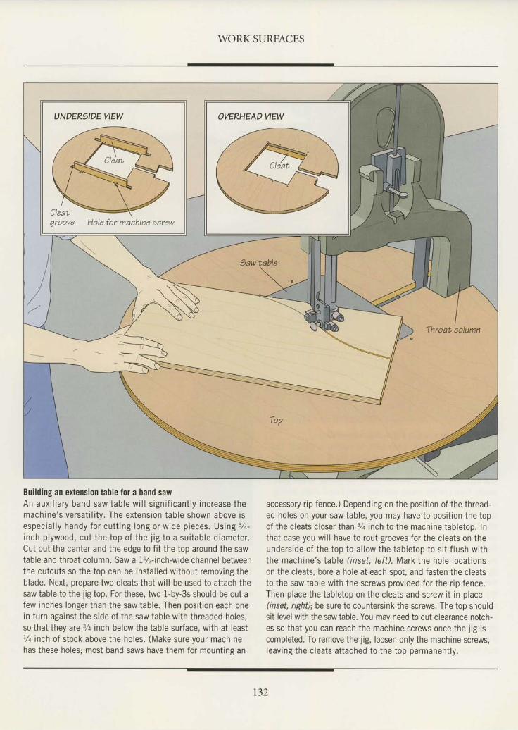
WORK SURFACES
Building an extension table for a band sawA n a u x i l i a r y b a n d s a w t a b l e w i l l s i g n i f i c a n t l y i n c r e a s e t h emach ine 's versa t i l i t y . The ex tens ion tab le shown above isespec ia l l y handy fo r cu t t ing long or w ide p ieces . Us ing 7a-inch p lywood, cu t the top o f the j ig to a su i tab le d iameter .Cut out the center and the edge to f i t the top around the sawtable and throat column. Saw a 1%-inch-wide channel betweenthe cutouts so the top can be instal led without removing theblade. Next, prepare two cleats that wi l l be used to attach thesaw table to the jig top. For these, two 1-by-3s should be cut afew inches longer than the saw table. Then posit ion each onein turn against the side of the saw table with threaded holes,so that they are 3/q inch below the table surface, with at leastt /q inch of stock above the holes. (Make sure your machinehas these holes; most band saws have them for mounting an
accessory r ip fence.) Depending on the posit ion of the thread-ed holes on your saw table, you may have to posrt ion the topof the cleats closer than 3/t inch to the machine tabletop. lnthat case you wi l l have to rout grooves for the cleats on theunders ide o f the top to a l low the tab le top to s i t f lush w i ththe machine's table ( inset, lef t) . Mark the hole locat ionson the cleats, bore a hole at each spot, and fasten the cleatsto the saw table with the screws provided for the r ip fence.Then place the tabletop on the cleats and screw i t in place(inset, right); be sure to countersink the screws. The top shouldsit level with the saw table. You may need to cut clearance notch-es so that you can reach the machine screws once the j ig iscompleted. To remove the jig, loosen only the machine screws,leaving the cleats attached to the top permanently.
t32
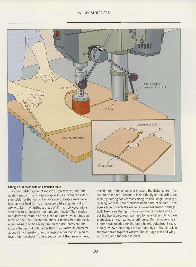
WORK SURFACES
Fitting a drill press with an extension tableThe smal l tab le typ ica l o f most d r i l l p resses w i l l no t ade-quately support many large workpieces. A customized exten-sion table for the tool wi l l enable you to keep a workpiecelevel as you feed i t into an accessory l ike a sanding drum(above). Start by cutting a piece of 7+-inch plywood into asquare with dimensions that sui t your needs. Then mark al ine down the middle of the piece and draw two circles cen-tered on the l ine. Locate one about 4 inches from the backedge, siz ing i t to f i t snugly around the dr i l l press column.Locate the second hole under the chuck; make its diameterabout r/z inch greater than the largest accessory you plan toinsert into the chuck. To help you pinpoint the center of hole,
instal l a bi t in the chuck and measure the distance from thecolumn to the bi t . Prepare to instal l the j ig on the dr i l l presstable by cutting two recesses along its back edge, leaving arectangular "ear" that protrudes behind the back hole. Thenbore a hole through the ear for a Vq-inch-diameter carriagebolt . Next, saw the j ig in two along the center l ine and cutout the two circles. You may need to make other cuts to clearprotrusions on your particular drill press. 0n the model shown,a notch was needed for the table height adjustment rack.Finally, screw a butt hinge to the front edge of the jig to jointhe two halves together (inset). The carriage bolt and wingnut w i l l c lamp the tab le in p lace .
t33
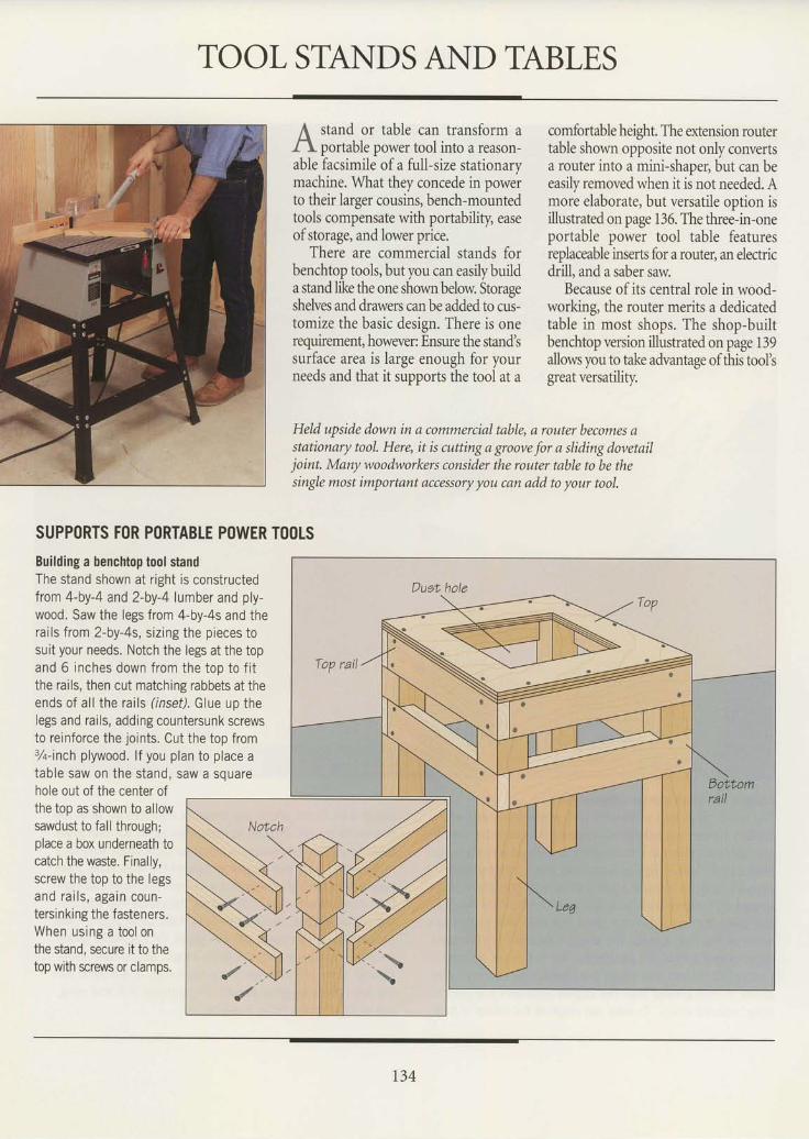
TOOL STANDSAND TABLES
stand or table can transform aportable power tool into a reason-
able facsimile of a full-size stationarymachine. What they concede in powerto their larger cousins, bench-mountedtools compensate with portability, easeof storage, and lower price.
There are commercial stands forbenchtop tools, but you can easily builda stand like the one shown below. Storaseshelves and drawers can be added to cui-tomize the basic design. There is onerequirement, however: Ensure the stand'ssurface area is large enough for yourneeds and that it supports the tool at a
comfortable height. The extension routertable shown opposite not only convertsa router into a mini-shaper, but can beeasily removed when it ii not needed, Amore elaborate, but versatile option isillustrated on page 136. The three-in-oneportable power tool table featuresreplaceable inserts for a router, an electricdrill, and a saber saw.
Because of its central role in wood-working, the router merits a dedicatedtable in most shops. The shop-builtbenchtop version illustrated on page 139allows you to take advantage of this tool'sgreat versatility.
HeId upside down in q commercial table, a router becomes astationary tool. Here, it is cutting a groove for a sliding dovetailjoint. Many woodworkers consider the router table to be thesingle most important accessory you can add to your tool.
SUPPORTS F()R PORTABTE POWER TOOLSBuilding a benchtop tool standThe stand shown at right is constructedfrom 4-by-4 and 2-by-4 lumber and ply-wood. Saw the legs from 4-by-4s and therai ls from 2-by-4s, s iz ing the pieces tosuit your needs. Notch the legs at the topand 6 inches down from the top to f i tthe rails, then cut matching rabbets at theends of al l the rai ls ( inset). Glue up thelegs and rails, adding countersunk screwsto reinforce the joints. Cut the top from3/o-inch plywood. lf you plan to place atable saw on the stand, saw a squarehole out of the center ofthe top as shown to allowsawdust to fall through;place a box underneath tocatch the waste. Finally,screw the top to the legsand ra i l s , aga in coun-tersinking the fasteners.When using a tool onthe stand, secure rt to thetop with screws or clamps.
Top rail
134
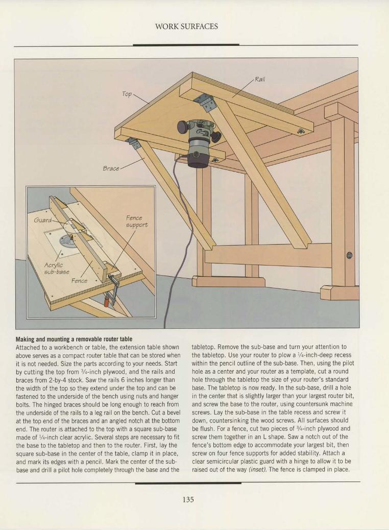
WORK SURFACES
Making and mounting a removable router tableAttached to a workbench or table, the extension table shownabove serves as a compact router table that can be stored whenit is not needed. Size the parts according to your needs. Startby cu t t ing the top f rom 3 /a- inch p lywood, and the ra i l s andbraces from 2-by-4 stock. Saw the rai ls 6 inches longer thanthe width of the top so they extend under the top and can befastened to the underside of the bench using nuts and hangerbolts. The hinged braces should be long enough to reach fromthe underside of the rai ls to a leg rai l on the bench. Cut a bevelat the top end of the braces and an angled notch at the bottomend. The router is at tached to the top with a square sub-basemade of l/q-inch clear acrylic. Several steps are necessary to fitthe base to the tabletop and then to the router. First , lay thesquare sub-base in the center o f the tab le , c lamp i t in p lace ,and mark i ts edges with a penci l . Mark the center of the sub-base and dr i l la pi lot hole completelythrough the base and the
tabletop. Remove the sub-base and turn your attent ion tothe tabletop. Use your router to plow a 7a-inch-deep recesswithin the penci l out l ine of the sub-base. Then, using the pi lothole as a center and your router as a template, cut a roundhole through the tabletop the size of your router 's standardbase, The tabletop is now ready. In the sub-base, dr i l l a holein the center that is s l ight ly larger than your largest router bi t ,and screw the base to the router, using countersunk machinescrews. Lay the sub-base in the table recess and screw i tdown, countersinking the wood screws. Al l surfaces shouldbe flush. For a fence, cut two pieces of 3/rinch plywood andscrew them together in an L shape. Saw a notch out of thefence's bottom edge to accommodate your largest bt t , thenscrew on four fence supports for added stabi l i ty. Attach aclear semicircular plast ic guard with a hinge io al low i t io beraised out of the way ( inset). The fence is clamped in place.
1 3 5
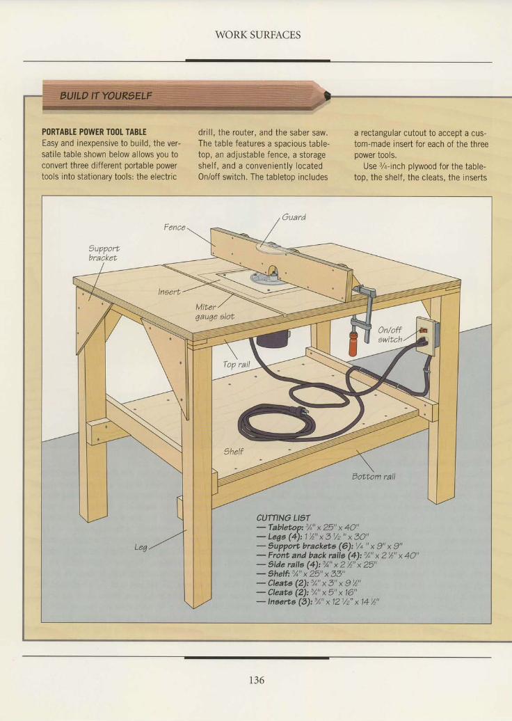
WORK SURFACES
PORTABTE POWER TOOI TABLEEasy and inexpensive to build, the ver-satile table shown below allows you toconvert three different portable powertools into stationarv tools: the electric
dr i l l , the router, and the saber saw.The table features a soacious table-top, an adjustable fence, a storageshelf , and a convenient ly locatedOn/off switch. The tabletoo includes
a rectangular cutout to accept a cus-tom-made insert for each of the threepower tools.
Use 3Z-inch plywood for the table-top, the shelf, the cleats, the inserts
Eottom rail
Le4
CUTflNG LIST- Tabletop:'1" x 25" x 40"- Lega (4): 1%" x 31/z " x 30"- Suppott bracketa (6):1/+ " x 9" x 9"- Front and back rails (4):5/o" x 2'/2" x 40"- 1lde raila (4): 5A" x 2 %" x 25"- thelfr "/o" x 25" x 33"- Cleats (2): %" x 3" x I %"- Cleate (2): %" x 5" x 16"- Inserte (3): 3A" x 121/2" x 14 %"
r36
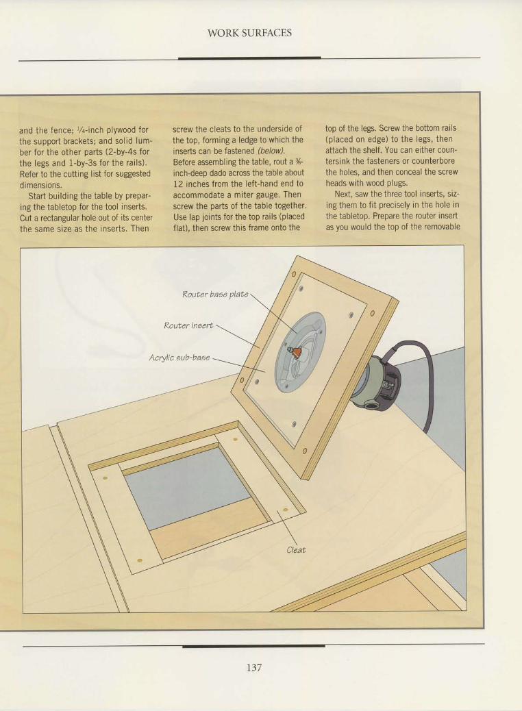
WORK SURFACES
and the fence; 14- inch plywood forthe support brackets; and sol id lum-ber for the other parts (2-by-4s forthe legs and 1-by-3s for the rai ls) .Refer to the cutting list for suggesteddimensions.
Start building the table by prepar-ing the tabletop for the tool inserts.Cut a rectangular hole out of its centerthe same size as the inserts. Then
screw the cleats to the underside ofthe top, forming a ledge to which theinserts can be fastened (below).Before assembling the table, rout a %-inch-deep dado across the table about12 inches from the lef t-hand end toaccommodate a miter gauge. Thenscrew the parts of the table together.Use lap joints for the top rails (placedflat), then screw this frame onto the
top of the legs. Screw the bottom rails(placed on edge) to the legs, thenattach the shelf. You can either coun-tersink the fasteners or counterborethe holes, and then conceal the screwheads with wood plugs.
Next, saw the three tool inserts, siz-ing them to f it precisely in the hole inthe tabletop, Prepare the router insertas you would the top of the removable
t37
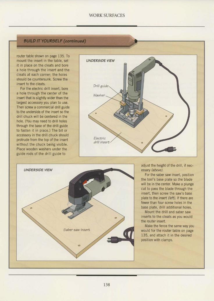
WORK SURFACES
router table shown on page 135. Tomount the insert in the table, setit in place on the cleats and borea hole through the insert and thecleats at each corner; the holesshould be countersunk. Screw theinsert to the cleats.
For the electric drill insert, borea hole through the center of theinsert that is slightly wider than thelargest accessory you plan to use.Then screw a commercial drill guideto the underside of the insert so thedrill chuck will be centered in thehole. (You may need to drill holesthrough the base of the drill guideto fasten i t in place.) The bi t oraccessory in the drill chuck shouldprotrude from the top of the insertwithout the chuck being vis ible.Place wooden washers under theguide rods of the dr i l l guide to
adjust the height of the drill, if nec-essary @bovel
For the saber saw insert, positionthe tool's base plate so the bladewill be in the center. Make a plungecut to pass the blade through theinsert, then screw the saw's baseplate to the insert (left). lt there arefewer than four screw holes in thebase plate, drill additional holes.
Mount the drill and saber sawinserts to the cleats as you wouldthe router insert.
Make the fence the same way youwould for the router table on page135, and attach it in the desiredposition with clamps,
138
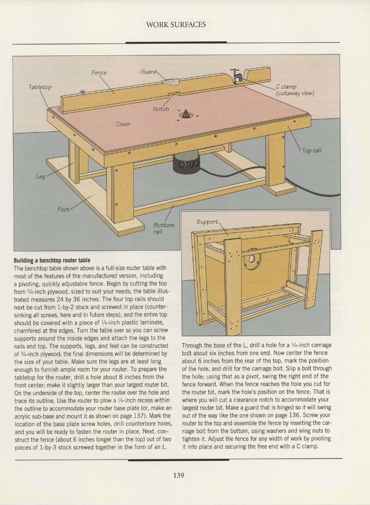
WORK SURFACES
Building a benchtop router tableThe benchtoo table shown above is a full-size router table withmost of the features of the manufactured version, includinga pivotrng, quickly adjustable fence. Begin by cutt ing the topfrom %-inch plywood, sized to sui t your needs; the table i l lus-trated measures 24 by 36 inches. The four top rai ls shouldnext be cut from 1-by-2 stock and screwed in place (counter-
srnking all screws, here and in future steps), and the entire topshould be covered with a piece of l/q-inch plastic laminate,chamfered at the edges. Turn the table over so you can screwsupports around the inside edges and attach the legs to therails and top. The supports, legs, and feet can be constructedof %-inch plywood; the f inal dimensions wi l l be determined bythe size of your table. Make sure the legs are at least longenough to furnish ample room for your router. To prepare thetabletop for the router, dr i l l a hole about 8 inches from thefront center; make it slightly larger than your largest router bit.On the underside of the top, center the router over the hole andtrace i ts out l ine. Use the router to plow a %-inch recess withinthe outline to accommodate your router base plate (or, make anacryl ic sub-base and mount i t as shown on page 137). Mark thelocat ion of the base plate screw holes, dr i l l counterbore holes,and you wi l l be ready to fasten the router in place. Next, con-struct the fence (about 6 inches longer than the top) out of twopieces of 1-by-3 stock screwed together in the form of an L.
Through the base of the L, drill a hole for a t/q-inch carrtagebolt about six inches from one end. Now center the fenceabout 6 inches from the rear of the top, mark the posit ionof the hole, and dr i l l for the carr iage bolt , Sl ip a bolt throughthe hole; using that as a pivot, swing the r ight end of thefence forward. When the fence reaches the hole you cut forthe router bit, mark the hole's position on the fence. That iswhere you wi l l cut a clearance notch to accommodate yourlargest router bi t . Make a guard that is hinged so i twi l lswingout of the way l ike the one shown on page 136. Screw yourrouter to the top and assemble the fence by inserting the car-riage bolt from the bottom, using washers and wing nuts totighten it. Adjust the fence for any width of work by ptvotingi t into place and securingthe free end with a C clamp.
r39

GLOSSARY
A.B-CBench dog: A round or square pegof metal or wood that fits into a holein a workbench to grip and hold aworkpiece in place.
Bevel cut: A cut at an angle fromface to face along the length or widthof a workpiece.
Box joint: Identical interlockingfingers that mesh to forma corner joint.
Butt joinery: A method of joiningwood in which the end or edge ofone board is set squarely againstthe face or edge ofanother.
Carcase: A box-like constructionthat constitutes the body of a pieceof furniture.
Cheek The face of the projectingtenon in a mortise-and-tenon joint.
Circuit: Continuous path for electri-cal current; from the main servicepanel in a house or garage, a branchcircuit runs to a series of outlets,wall switches, and light fixtures, andreturns to the panel.
Counterbore: To drill a hole thatpermits the head of a screw or boltto sit below a wood surface so it canbe concealed by a wood plug.
Countersink: To drill a hole so thatthe head of a screw or bolt will lieflush with or slightly below the sur-face of a workpiece.
Crosscut A saw cut across the woodgrain of a workpiece.
D-E-FDado: A rectangular channel cutinto a workpiece.
Decibeh The standard measuringunit of sound intensity; the decibel(db) scale extends from 0 to about130, with 0 representing barelyperceptible sounds and 130 delin-eating the average pain level.
Dedicated circuifi An electrical cir-cuit to which only one tool or fixtureis connected.
Dovetail joinery: A method ofjoining wood at corners by meansof interlocking pins and tails; thename is derived from the distinc-tive shape cut into the ends ofthe joining boards.
Dowek A wood pin used to rein-force certain types of wood joints.
End cap: A piece ofwood that coverseach end of the top slab of a work-bench; bolted to the slab and gluedto the aprons by means of dovetailor finger joints.
Face gluing: Bonding severalboards together face-to-face toform a thicker workpiece.
Face jointing: Using a jointer tocut shavings from the face ofaworkpiece until it is flat and squarewith the edge.
Face viss A vise that holds workagainst the front apron of a work-bench.
Featherboard: A piece ofwood cutwith thin fingers or "feathers" at oneend; used in conjunction with clampsto hold a workpiece secure againstthe fence or table of a power tool.
Fence: An adjustable guide designedto keep the edge or face of a work-piece a fixed distance from the cut-ting edge of a tool.
Furring strip: A thin board that isnailed to a wall or ceiling to providea flat or level surface for securingdrywall or paneling.
G-H-r-JGround-fault circuit interrupter(GFCI): A tFpe of electrical outletthat trips instantly when it detectsa short-circuit leak in current.
Hanger bolt A bolt with no head;one end of the bolt has screwthreads while the other end fea-tures machine threads.
Inlay: A decorative strip of metal,hardwood, or marquetry that is gluedin a groove cut into a workpiece.
Joist: A horizontal support fora floor.
140
GLOSSARY
K-LKerf: A cut made in wood bythethickness of a sawblade.
Kerf splitter: A metal device thatholds a kerf slightly open during asaw cut to prevent the blade frombinding.
Kickback The tendency of a work-piece to be thrown back in the direc-tion of the operator of a power tool.
Knockdown fitting: A piece ofhardware that accepts a screw orbolt, allowing the quick assemblyand disassembly of a workbenchor other furniture.
Lap joint A typ" ofjoint in whichmatching dadoes or rabbets overlapto connect two boards.
Lead anchor: A type of fitting thatis inserted into a hole in concreteor masonry; expands to hold a screwor bolt securely.
Legvise: A vise that secures stockto the front left-hand leg of a work-bench.
M-N-O-P-Q-R-SMiter cut A cut that angles acrossthe face of a workpiece.
Mortise: A rectangular, round,or oval-shaped hole cut into a pieceofwood.
Mortise-and-tenon: A joint inwhich a projecting tenon on oneboard fits into a mortise on another.
Push block or stick A device usedto feed a workpiece into the blade,cutterhead, or bit ofa tool to protectthe operator's fingers.
Rabbet A step-like cut in the edgeor end of a workpiece; usually formspart of a joint.
RaiL A board running along thebottom edge of a tabletop to whichthe legs ofa table can be attached.
Service entrance: A box contain-ing circuit breakers or fuses, fromwhich power is distributed to housebranch circuits.
Shoulder: In a mortise-and-tenonjoint, the part of the tenon that isperpendicular to the cheek.
Shouldervisq A fixed type offacevise with a jaw that moYes to clampa workpiece against the front apronofa workbench.
Sliding dogbloclc A wood block,part of the tail vise of a workbench,that applies the clamping face to holda workpiece between the bench dogs.
Static pressurs A measure of thefriction encountered by air as itmoves through a duct; oftenexpressed in inches per foot.
Stretcher: A board running betweenthe legs of a workbench to provideadditional support.
Stud: A vertical member formingwalls and supporting the frameworkof a building.
T.U-V-W-X-Y-ZTirilvise: A screw-type vise on theright-hand end of a workbenchincorporating a sliding dog blockto secure stock on the top surfaceofthe bench.
Tenon: A protrusion from the endof a board that fits into a mortise.
Truing: Squaring the end of a bladeor the working surface of a grinderwheel so that it conforms to its orig-inal shape.
Truss rod: A type of threaded metalrod used to reinforce the legs andstretchers of a workbench.
Wheel dresser: A star-wheel or dia-mond-point device used to true theworking surface of a grinding wheeland expose fresh abrasive particles.
t4r

INDEX
Page references in ltalics indicatean illustration of subject matter.Page references in bold indicatea Build It Yourself project.
A B CAir compressors, 69, 70, 72, 73Air-powered tooIs, 68, 72- 73Attics:
Workshop layout, 38Axtell, Peter, 6-7Band saws:
Curved cutscircle-cutting support jigs, 128
Dust collection systems, 82, 85Extension tables, 111, 132Workshop IayouI-, j2, 38
Bar clamps:Shop-made glue racks (Shop Tip), 12aStorage, 106, 107
storing clamps in a garbage can(Shop Tip), 106
Basements:Workshop layout,39
Bench dogs, 62-63Carving dogs,64Edgedogs,63Holes,54,54
Bench grinders,71,76Gouge-sharpe ning jrgs, 77Workshop layout, 34
Bench slaves. 122Black & Decker Workmater",47, 112Build It Yourself:
Bench grindersgouge-sharpening jigs, 77
Safety equipmentfeatherboards, 22push sticks,20-21
Shop layoutshop dollies, 37
Storagefold-down workbench and tool
cabinet,98-99, I10handsaw holders, 101lumber-and-plywood racks, 91mobile clamp racks, 105scrapboxes, 109shelves for clamps, 106tool cabinets,95tool cupboards,96
Workbenchesbench dog holes, 54edgedogs, 63sliding bench stops, 6l
Work surfacesIibrary-type work tables, 113portable power tool tables, 136-138
Carving dogs,64
Circular saws:BIades
circular sawblade carriers (ShopTip), 102
storage, 102Clamps:
Storage, LO5,106, 107Storing handscrews (Shop Tip), 107
Collins, Martha, 8-9Compressed-air tools. See Air-powered
tools
D EDoors:
Opened-door signalssafe attention getters (Shop Tip), 37
Dowel racks, 90Drill presses:
Extension tables, .133Workshop layout, 33
Drills:Nr-powered,,72See also Electric drills
Dust collection systems, 69, 70, 78-81Dust hoods, 82-84
adapting standard sheet metal ductsas dust hoods (Shop Tip), 83
Electrical sweeps for right-angle joints(Shop Tip), 81
Portable,85,87shop vacuums, 71,85, 87
Shop-made blast gates (Shop Tip), 84Vacuum screening ramps (ShopTip), 86
Electrical systems:Electrical shock,27Portable generators, 7 1, 74-75Power cord covers (Shop Tip),42Power tool ratings, 75Safetyprecautions, IZShop layout, 41-42,44
Electric drills:Tables, 136-138
Emergency procedures:Fire, 16See also First aid; Safety precautions
Extension cords, l7
F G H I IFasteners:
Anchoring lumber racks in concrete(Shop Tip), 93
Storage, 108,109Featherboards, 22Finishes:
Safety precautions, 14, 15Fire, 13, 16Fire extinguishers, 16Fftstaid.23-27
Eyes,24Shock,26
electrical,27Wounds,25-26
Garages:Workshop layo:ut, 36,40
Generators, 71,74-75GIue racks:
Shop-made glue racks (Shop Tip), 124Ground-fault circuit interrupters
(GFCIs) ,17Handsaws:
Storage, 100,101Hand tools, /ront endpaper
Safety precautions, 14Hearing protection, .18, 19Heating systems,45Hickman, Ron,47, 112High-volume, low-pressure (HVLP)
,. spray systems, 70J lgs:
Band sawscircular cuts, 128
Bench dog holes, 54Bench grinders
gouge-sharpening jigs, 77Vises
stepped blocks to prevent racking, 6.1Workbenches
bench stops, 61,65-67carving dogs,64edgedogs,63wooden inserts for metal-jawed
vises, 60Iointer/planers:
Workshop layout, 33Iointers:
Push blocks. 2lWorkshop layout, 33, 38
K L M N OLathes:
Workshop layout, 33Lee, Leonard, l0-llLighting:
Bench-dog lamp support (ShopTip), a3
Shop Layout, 43Lumber:
Sizes, back endpaperLumber racks, 94 9l
Adjustable, 92-9jAnchoring lumber racks in concrete
(Shop Tip), 93Multitesters, T0Nail guns:
Air-powered,73Outfeed tables, 125, I 29- I 33
P Q RPipe clamps:
Storage, 106, 107storing clamps in a garbage can
(Shop Tip), 106Planers:
Dust hoods. 82
t42

Plywood:Storage racks,91
Power tools:Hanging portable power tools from
the wall (Shop Tip), l0.lMultipurpose, 30Safety precautions, 14
disabling a power tool (ShopTip), 14
featherboards, 22noise levels, -19push sticks,20-21
Wattage ratings, 75Workshop placement, 30
space and light requirements, 32-34See also Lir-powered tools
Protective clothing, 13, 18- 19Push sticks, 20-21Radial arm saws:
Dust hoods, 82Extension tables, 130Workshop Iayout, j2
Respirators, 18, 19Roller stands, 125- 126Routers:
Air-powered,73Tables, 134, 136- 137, 139
dust hoods, 83removable router tables, 135workshop layout, 32
S T U VSaber saws:
Tables, f36-f38Safety precautions, 13
Anti-fatigue mats,44Compressed air, 73Door-opened signals
safe attention-getters (Shop Tip), 37Electrical systems, 12Finishes, 14, l5Flammable products, 89Generators, 75Hand tools. 14Power tools, 14
disabling a power tool (ShopTip), 14
Protective clothing, 13, 18- 19Tool storage,94See also Toxic substances
Sanders:Air-powered, 68, 72Sanding stations, 84Storing sanding disks (Shop Tip), 108Workshop layout, 34
Sawhorses, 118-120FoIding, 122Heavy-dfiy, 121Padding sawhorses (Shop Tip), 120Panel support frames, 123Securing workpieces edge-up on
sawhorses (Shop Tip), 122Shop-made glue racks (Shop Tip), 124
Stacking sawhorses (Shop Tip), lI9Scrapboxes, 109Scroll saws:
Workshop layott,34Shapers:
Workshop layout, 33Shop dollies,37Shop Tips:
Dust collection systems, 81,83, 84,86,87
Safety precautions, 14Storage systems, 93, 101, 102, 104, 106,
107, 108Workbenches, 60, 64Workshop layout, 37, 42, 43, 44Work surfaces, 117, 119, 120, 722, 124,
129Shop vacuums, 71,85
Panty-hose shop vacuum filters (ShopTip),87
Smoke detectors, l6Solvents, 15Spray guns:
Ait-powered,72Storage systems, 8-9, 89
Flammable products, 89Tool chests, 88TooIs, 94-95, 96, 97, 103- 104
clamp racks, 105, 106fold-down workbench and tool
cabinet, 98-99, 110handsaw racks, 104 101hanging portable power tools from
the wall (Shop Tip), JOImagnetic tool racks (Shop Tip), 104
See alsoLtmber racksTables, l l l ,112
Assembly and finishing tables, 34Extension tables, 1 29- 1 3 3
double-duty work tables (ShopTip),129
Library-type work tables, 113Low assembly tables, 114Stow-away tables, 1 1 5- 1 1 6Temporary, 117
stabilizing a temporary worksurface (Shop Tip), 117
See also WorkbenchesTable saws:
Extension tables, 129double-duty work tables (Shop
Tip), 129fold-down outfeed tables, I3-l
Safety devices, 12Wheel bases,29
table saw on wheels (Shop Tip), 3iWorkshop layout, 29, 31, 32
Telephones:Visual ringing signals, 37
Toxic substances:rlnrsnes. 15Woods, back endpaper, 13, 15
Ventilation systems, 45
Positive-pressure ventilation, 86See also Dust collection systems
Vises:Extension slands,127Workbenches, 56
face vises, 56, 58- 59, 60, 61quick-switch vises (Shop Tip), 60
tail vises, 56-57, 60, 62wooden inserts for metal iaws, 60
W X Y ZWheel dressers,71,76Wide panels:
Circle-cutting support jigs, 128Support frames, 123Table saws, 129
Wood:Toxic effects, back endpaper, 13, 15See alsoLumber
Workbenches, 10-ll, 46-49Bases, 50-52Bench hooks, 66, 67Bench stops, 65-67
sliding bench stops, 61Black & Decker Workmater',4T, 112Carving screws (Shop Tip),64Fold-down workbench and tool
cabinet, 98-99, 110Hold-downs,65Tops,43-55Vises, 56
face vises, 56, 58-59, 60, 61tail vises, 56-57, 60, 62wooden inserts for metal jaws, 60
Workshop layo:ut, j4See also Bench dogs
Workshop layout,29-31Dust collection systems, 78Electrical systems, 41-42, 44Floorc,44Large spaces, 40Lighting, 43Medium-sized spaces, 39, 42Scale drawings, 28, 30, 36, 39, 40, 42
tools, 35Small spaces, 36-39
Workshops:Ceilings,44Floors, 44
making the transition to a raisedfloor (Shop Tip),44
power cord covers (Shop Tip),42Heating systems, 45Planning,6Ventilation systems, 45, 86Walls,44See also Dust collection systems;
Workshop layoutWork surfaces:
Tool stands, 134, 135,136-138,139Variable-height work strfaces, 1 24S ee also T ables; Workbenches
r43

ACKNOWLEDGMENTS
The editors wish to thank the following
SAFETYAdjustable Clamp Co., Chicago, IL; Black & Decker/Elu Power Tools, Towson, MD; Delta International
Machinery/Porter Cable, Guelph, Ont.; Fisher Hill Products, Inc., Fitzwilliam, NH; Freud Westmore Tools, Ltd.,Mississauga, Ont.; Lee Valley Tools Ltd., Ottawa, Ont.; Sears, Roebuck and Co., Chicago, IL;
Vermont American Corp., Lincolnton, NC and Louisville, KY
SHOPLAYOUTBlack & Decker Power Tools, Towson, MD; Delta International Machinery/Porter Cable, Guelph, Ont.;
Hitachi Power Tools U.S.A. Ltd., Norcross, GA; Lee Valley Tools Ltd., Ottawa, Ont.; Sears, Roebuck and Co.,Chicago, IL; Thoroughbred Sawhorses and Equipment, Division of the Ivy Group, Inc., Valparaiso, IN
WORKBENCHAdjustable Clamp Co., Chicago, IL; Black & Decker/Elu Power Tools, Towson, MD; Delta International Machinery/Porter
Cable, Guelph, Ont.; Freud Westmore Tools, Ltd., Mississauga, Ont.; Great Neck Saw Mfrs. Inc. (Buck Bros. Division),Millbury, MA; Hitachi Power Tools U.S.A. Ltd., Norcross, GA; The Workbench Book (Taunton Press, 1987) by Scott Landis;
Lee Valley Tools Ltd., Ottawa, Ont.; Record Tools Inc., Pickering, Ont.; Robert Larson Compann Inc., San Francisco, CA;Sandvik Saws and Tools Co., Scranton, PA; Sears, Roebuck and Co., Chicago, IL; Thoroughbred Sawhorsesand Equipment, Division of the Iry Group, Inc., Valparaiso, IN; Vermont American Corp., Lincolnton,
NC and Louisville, KY; Woodsmirh,2200 Grand Ave., Des Moines, 1A50312
SHOPACCESSORIESCampbell Hausfeld, Harrison, OH; Delta International Machinery/Porter Cable, Guelph, Ont.; Dewalt Industrial
Tool Co., Hampstead, MD; Great Neck Saw Mfrs. Inc. (Buck Bros. Division), Millbury, MA; Ingersoll-RandCanada Inc., Rexdale, Ont.; Sears, Roebuck and Co., Chicago, IL; Wagner Spray Tech Corp., Minneapolis, MN
STORAGEAdjustable Clamp Co., Chicago, IL; American Tool Cos., Lincoln, NE; Freud Westmore Tools, Ltd., Mississauga, Ont.;
Hitachi Power Tools U.S.A. Ltd., Norcross, GA; The Workshop Book (Taunton Press, 1991) by Scott Landis;Lee Valley Tools Ltd., Ottawa, Ont.; Robert Sorby Ltd., Sheffield, U.K./Busy Bee Machine Tools, Concord, Ont.;
Sandvik Saws and Tools Co., Scranton, PA; Stanley Tools, Division of the Stanley Works, New Britain, CT;Vermont American Corp., Lincolnton, NC and Louisville, KY
WORKSURFACESAdjustable Clamp Co., Chicago, IL; Black & Decker Power Tools, Towson, MD; Delta International Machinery/Porter Cable,
Guelph, Ont.; Freud Westmore Tools, Ltd., Mississauga, Ont.; Hitachi Power Tools U.S.A. Ltd., Norcross, GA; The Workshop Book(Taunton Press, 1991) by Scott Landis; Lee Valley Tools Ltd., Ottawa, Ont.; Record Tools Inc., Pickering, Ont.;
Sandvik Saws and Tools Co., Scranton, PA; Sears, Roebuck and Co., Chicago, IL; Shopsmith, Inc., Montreal, Que.; Stanley Tools,Division of the Stanley Works, New Britain, CT; Thoroughbred Sawhorses and Equipment, Division of the Ivy Group, Inc.,Valparaiso, IN; Tru-Align Manufacturing Inc., Tempe, AZ; Vermont American Corp., Lincolnton, NC and Louisville, KY
The following persons also assisted in the preparation of this book:
Ren6 Bertrand, Elizabeth Cameron, Donna Curtis, Lorraine Dor€, Rdjean Garand, Graphor Consultation,Irene Huang, Carolyn Jackson, Leonard Lee, GeneviEve Monette
PICTURE CREDITS
Cover Robert Chartier6,7 Robert Holmes
8,9 Raymond Gendreau10, ll Ron Levine
30 Courtesy Shopsmith, Inc.47 Courtesy Sjcibergs of Sweden
49 Courtesy Woodcraft Supply Corp.70 Courtesy Makita Canada Ltd.
89 Courtesy Iustrite Manufacturing Co.l12 (upper) Courtesy Shure Manufacturing Corp.
t44

IItttIttIIIIIIIItIIIIIIIIIIIItI.r
WORKSHOP GUIDE
Toxtc w00DsProtecting yourself from toxic speciesThe dust from many wood species can pose healthrisks ranging from respiratory ailments to skin anceye irritations. Some woods contain chemicals thatcan cause toxic effects (page 10. The chart belowl ists a number of species and their possible healtheffects. To reduce direct exposure to dust from awood that may trigger an allergic reaction, keep yourshop clean and wel l vent i lated, and wear a dust maskfor cutt ing,operat ions. Before handl ing the species,spread a barrier cream on your skin or wear protectivegear, including long pants and sleeves, gloves, and^ ^ J ^ + . , ^ l ^ ^ ^ ^ ^5drur .y Brd55cs .
Arbor vitaeAshBlack cherry R SBlack soruce R SBoxwood R SCalifornia redwood R S TCashewChestnut R SCocobolo R SDouglas-fir R SEbony R S TEuropean larch R SEUrOpean spruce R Slmbuia R Slroko R SLacewood R SMahogany, African R SMahogany, South American R S T0ak R SPine R SRed cedar R SRosewood. BrazilianRosewood, East IndianSatinwood, CeylonSilky oak R STeakWalnut R SWenge R SWestern red cedar R S IWhite cedar
R = Respiratory ailmentsS = Skin and eye irritationsT = Toxic effects
R S T
1{0M[{At Al{D ACTUATSOFTWOOD TUMBER SIZES
ilominal(lnches)
Actual(lnches)
Surfaced dry Surfaced green
l-by-2 3h-by-It/z 25h2-by-IeA6
1-by-3 3/+-by-21/z 25/zz-by-2eA.o
1-by-4 3/q-by-3r/z 25/zz-by-3e/rc
1-by-6 3h-by-5t/z 25/zz-by-55/a
1-by-8 3h-by-7th 25Az-by-7Vz
1-by-10 3h-by-9|h
I-by-12 3h-by-Ilth 25/zz-by-I Ir/z
2-by-2 I1/z-by-Ir/z Ts/rc-by-leAo
2-by-4 I1/z-by-31/z Ie/rc-by-3e/rc
2-by-6 Ir/z-by-St/z Iehe-by-55/a
2-by-8 Ir/z-by-7th leAa-by-7 Vz
2-by-I0 lVz-by-91h Ie/rc-by-9Vz
2-by-12 I1/z-by-IIth Is/rc-by-IIVz
3-by-4 2t/z-by-3t/z 2sAo-by-3s/rc
4-by-4 3r/z-by'3r/z 3e/rc-by-3e/rc
4-by-6 3Vz-by-51/z 3eAe -by-55/a
STAI{DARD THICKI{ESSESFOR SURFACED HARDWOOD
l{ominal(rough)
Actual(surfaced two sides)
3An 3/:.a"
v'%' %ott
,1. slu"
1 u %" o r '%e"
7Yo' IrAe"
T''' I5lu"
2', l%" o r I%"
3' 23/o'
3%',4"