essentials of woodworking; a textbook for schools
TRANSCRIPT
Class L
Book. OLi
Copyright}!^.
COPYRIGHT DEPOSED
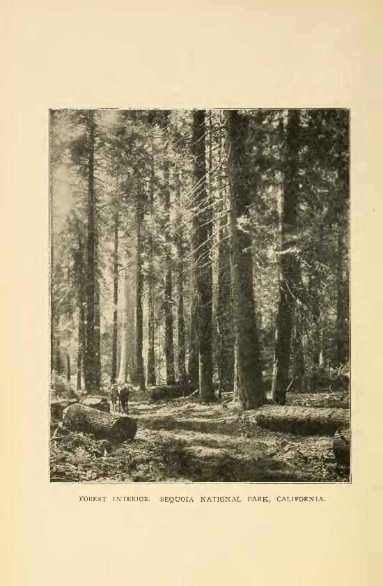
FOREST INTERIOR. SEQUOIA NATIONAL PARK, CALIFORNIA.
ESSENTIALS OFWOODWORKINGA TEXTBOOK FOR SCHOOLS
BY
Ira Samuel Griffith, A. B*-.
ILLUSTRATIONS BY
Edwin Victor Lawrence
The Manual Arts PressPeoria, Illinois
XLIBRARY of CONGRESS
Tv/0 Copies Received
NOV \2 1908
^ Copyngnt entry _,
CLAsk O- KXc, No,
\
Copyright
Ira Samuel Griffith1908
^-33^90
PREFACE.
An experience, somewhat extended, in teaching aca-
demic branches of learning as well as woodworking, has
convinced the author that the most effective teaching of
woodworking can be accomplished only when its content
is made a subject of as diligent study as is that of the
other and older branches. Such a study necessitates the
possession, by the student, of a text-book.
The selection of a suitable text is made difficult be-
cause of the fact that tool processes are usually treated
in connection either with models or exercises. It is hardly
to be expected that any one set of models or of exercises,
tho they may be of very great value, will fill the needs of
varying local school conditions. The production of a text-
book which shall deal with tool processes in a general
way without reference to any particular set of models or
exercises is the author's aim. It is believed that such a
text will prove suitable wherever the essentials of wood-
working shall be taught, whether in grammar, high
school or college, and whatever the system of instruction.
A few words as to the manner of using the text seem
advisable. It is not expected that the book will be stud-
ied chapter by chapter, consecutively, as are the elemen-
tary texts in mathmatics or science. Rather, it is to be
studied topically. To illustrate : A class is to make a mod-
el, project, exercise, or whatever we may choose to call it,

2 ESSENTIALS OF WOODWORKING.
which will require a knowledge of certain tools and the
manner of using them. At a period previous to their in-
tended use the numbers of the sections of the text relating
to these tools and their uses, or the page numbers, should
be given the student. Previous to the period in which
these tools are tO' be used he should be required to study
the sections so marked. The recitation upon the assigned
text should take place at the beginning of the period fol-
lowing that of the assignment, and may be conducted in
a manner quite similar to that of academic branches.
This should prepare the way and make intelligible the
"demonstration" which may be given in connection with
the recitation or at its close.
If as thoro a knowledge of the matter studied is in-
sisted upon in the recitation as is insisted upon in the
academic classroom, there need be but little excuse for
ignorance on the part of the pupil when he begins his
work or at any subsequent time.
Acknowledgement is due the Department of Forestry,
Washington, D. C, for the use of material contained in
the chapter on Woods and for the prints from which
many of the half-tones relating to forestry, were pro-
duced.
INTRODUCTION.
Care of Tools and Bench.
It is important that a beginner should become im-
pressed with the importance of keeping his tools in the
best condition. Good results can be obtained only when
tools are kept sharp and clean, and used only for the pur-
poses for which they are made. Tools properly shari>
ened and properly used permit one to work easily as well
as accurately. When it becomes necessary for the work-
er to use undue strength because of the dullness of his
tools, ''troubles" begin to accumulate and the ''pleasure
of doing" is soon changed to despair.
Orderliness and carefulness, with knowledge and
patience are sure to bring good results;just as a lack of
them will bring failure.
The bench top must not be marked with pencil or
scratched unnecessarily. Chisel boards are to protect the
top from any accidental cuts and should always be used
for that purpose. Bench tops that are scraped and shel-
laced or oiled every other year ought to remain in as good
condition as when new except for the few accidental
marks too deep to remove, which the thoughtless boy may
have inflicted.
Good workers take pride in keeping their benches in
o^ood order. Tools that are not in immediate use should
4 ESSENTIALS OF WOODWORKING.
be placed in their racks that they may not be injured or
cause injury to the worker. At the close of the period
the bright parts of tools that have come in contact with
perspiring hands should be wiped off with oily waste kept
for that purpose. All tools should then be put away in
their proper places and the top of the bench brushed clean.
The beginner should also understand that, important
as are the results he may be able to produce in wood,
more serious results are being produced in himself in the
habits he is forming. Carefulness, neatness, accuracy,
ability to economize in time and material, ability to
''think" and ''to do" because of the thinking, honesty, or-
derliness—these are some of the more important results
that are oftentimes overlooked.
CONTENTS.
Introduction.
Care of tools and bench 3
PART I.
Tools and Elementary Processes.
Chapter I.—Laying-out Tools ; Their Uses 9
I. The rule; 2. The try-square; 3. The framing
square ; 4. The bevel ; 5. The marking gage ; 6. The
pencil gage ; 7. Splitting gage ; 8. The mortise gage
;
9. The Dividers; 10. Pencil and knife.
Chapter II.—Saws . .
' 20
II. Saws; 12. The crosscut saw; 13. The rip-saw;
14. The back-saw; 15. The turning saw; 16. The
compass saw; 17. Saw filing.
Chapter III.—Planes 28
18. Planes; 19. Setting the blade ; 20. Adjustment of
the iron; 21. The jack-plane; 22. The smooth-plane;
23. The jointer; 24. The block-plane; 25. The wood-
en plane; 26. Planing first surface true; 27. Face
side, face edge; 28. Planing first edge square with
face side ; 29. Finishing the second edge ; 30. Finish-
ing the second side ; 31. Planing the first end square
;
32. Finishing the second end; 33. End planing with
the shooting board ; 34. Rules for planing to dimen-
sions ; 35 Planing a chamfer.
6 ESSENTIALS OF WOODWORKING.
Chapter IV.—Boring Tools 46
36. Brace or bitstock ; 37. Center bit ; 38. The auger
bit; 39. The drill bit; The gimlet bit; 40. Counter-
sink bit; 41. The screwdriver bit; 42. The brad-awl;
43. Positions while boring; 44. Thru boring; 45.
Boring to depth.
Chapter V.—Chisels and Chiseling 53
46. Chisels; 47. Horizontal paring across the grain;
48. Vertical paring; 49. Oblique and curved line par-
ing; 50 Paring chamfers; 51. The firmer gouge; 52.
Grinding beveled edge tools; 53. Whetting beveled
edge tools ; 54. Oilstones ; 55. Sharpening the chis-
el ; 56. Sharpening plane-irons ; 57. To tell whether
a tool is sharp or not.
Chapter VI.—Form Work ; Modeling 65
58. Making a cylinder; 59. The spokeshave; 60.
Making curved edges; 61. Modeling.
Chapter VII.— i. Laying Out Duplicate Parts ; 2. Scrap-
ing and Sandpapering; 3. Fastening Parts 70
62. Laying out duplicate parts ; 63. Scraping ; 64.
Sandpapering ; 65. Hammers ; 66. Nails ; 67. Nail-
ing; 68. Nailset; 69. Withdrawing nails; 70. The
screwdriver; 71. Screws; 72. Fastening with screws;
73. Glue; 74. Clamps; 75. Gluing.
PART 11.
Simple Joinery.
Chapter VIII.—Type Forms 84
76. Joinery; 77. General directions for joinery; 78.
Dado; 79. Directions for dado; 80. Cross-lap joint;
CONTENTS. 7
81. Directions for cross-lap joint, iirst method; 82.
Directions for cross-lap joint, second method; 83.
Glue joint; 84. Directions for glue joint; 85. Dow-eling; 86. Directions for doweling; 87. Keyed ten-
on-and-mortise ; 88. Directions for key; 89. Direc-
tions for tenon; 90. Directions for mortise; 91.
Directions for mortise in the tenon; 92. Blind mor-
tise-and-tenon ; 93. Directions for tenon ; 94. Direc-
tions for laying out mortise; 95. Directions for cut-
ting mortise, iirst method; 96. Directions for cut-
ting mortise, second method; 97. Miter joint; 98.
Directions for miter joint; 99. Dovetail joint; 100.
Directions for dovetail joint.
Chapter IX.—Elementary Cabinet Work 105
101. Combination plane; 102. Drawer construction;
103. Directions for rabbeted corner; 104. Direc-
tions for dovetail corner; 105. Directions for draw-
er; 106. Paneling; 107. Cutting grooves; 108.
Haunched mortise-and-tenon ; 109. Rabbeting; 110.
Fitting a door; 111. Hinging a door; 112. Locks..
PART III.
Wood and Wood Finishing.
Chapter X.—Wood 116
113. Structure; 114. Growth; 115. Respiration and
transpiration; 116. Moisture; 117. Shrinkage; 118.
Weight; 119. Other properties; 120. Grain.
Chapter XL—Lumbering and Milling 126
121. Lumbering; 122. Milling; 123. Quarter saw-
ing; 124. Waste; 125. Lumber transportation; 126.
Seasoning; 127. Lumber terms and measurements
8 ESSENTIALS OF WOODWORKING.
Chapter XII.—Common Woods 138
128. Classification. Coniferous woods. 129. Cedar;
130. Cypress; 131. Pine; 132. Spruce. Broad-leaved
woods; 133. Ash; 134. Basswood; 135. Birch; 136.
Butternut; 137. Cherry; 138. Chestnut; 139. Elm;140. Gum; 141. Hickory; 142. Maple; 143. Oak; 144.
Sycamore; 145. Tulip wood; 146. Walnut,
Chapter XIII.—Wood Finishing 150
147. Wood finishes; 148. Brushes; 149. General
directions for using brush; 150. Fillers; 151. Fill-
ing with paste filler; 152. Stains; 153. Waxing;154. Varnishes; 155. Shellac; 156. Shellac finishes;
157. Oil or copal varnishes; 158. Flowing copal var-
nish; 159. Typical finishes for coarse-grained woods;
160. Patching; 161. Painting.
Appendix I.—Additional Joints 164
Appendix II.—Wood Finishing Recipes 171
1. Wax; 2. Water stains; 3. Oil stains; 4. Spirit
stains.
Appendix III.—Working Drawings 173
1. Instruments; 2. Conventions; 3. Projection and
relation of views; 4. Letters and figures; 5. Con-
structions ; 6. Order of procedure.
CHAPTER I.
Laying-Out Tools—Their Uses.
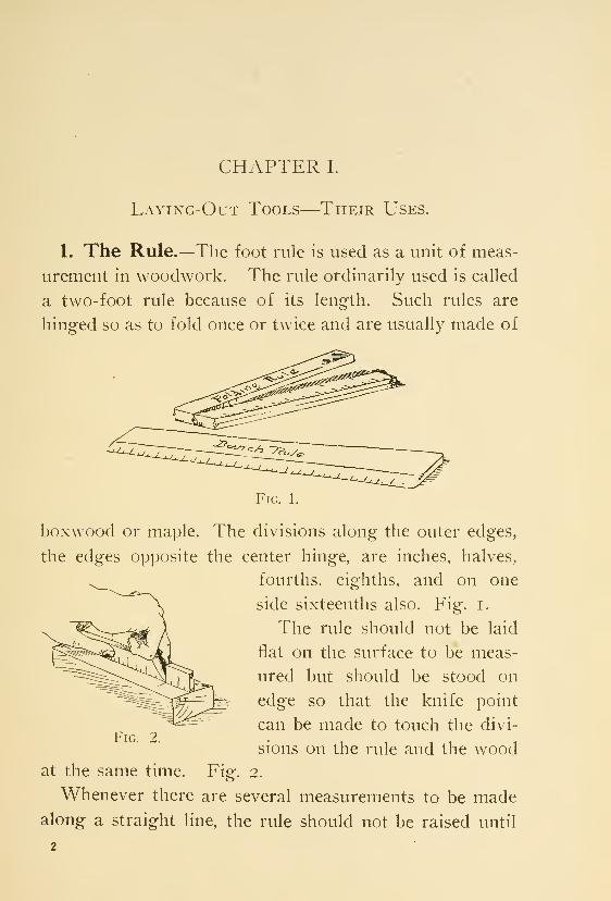
1. The Rule.—The foot rule is used as a unit of meas-
urement in woodwork. The rule ordinarily used is called
a two-foot rule because of its length. Such rules are
hinged so as to fold once or twice and are usually made of
Fig. 1.
boxwood or maple. The divisions along the outer edges,
the edges opposite the center hinge, are inches, halves,
fourths, eighths, and on one
side sixteenths also. Fig. i.
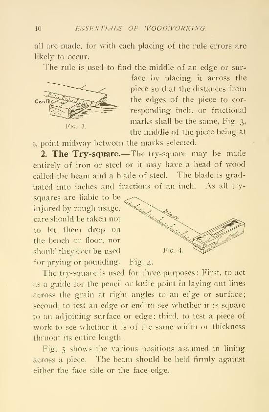
The rule should not be laid
flat on the surface to be meas-
ured but should be stood on
edge so that the knife point
can be made to touch the divi-
sions on the rule and the woodat the same time. Fig. 2.
Whenever there are several measurements to be madealong a straight line, the rule should not be raised until
Fig. 2.
10 ESSENTIALS OF WOODWORKING.
Ccnleis
all are made, for with each placing of the rule errors are
likely to occur.
The rule is used to find the middle of an edge or sur-
face by placing it across the
piece so that the distances from
the edges of the piece to cor-
responding inch, or fractional
marks shall be the same, Fig. 3,
the middle of the piece being at
a point midway between the marks selected.
2. The Try-square.—The try-square may be made
entirely of iron or steel or it may have a head of w^ood
called the beam and a blade of steel. The blade is grad-
uated into inches and fractions of an inch. As all try-
squares are liable to be
Fig. 3.
injured by rough usage,
care should be taken not
to let them drop on
the bench or floor, nor
should they ever be used
for prying or pounding. Fig. 4.
The try-square is used for three purposes : First, to act
as a guide for the pencil or knife point in laying out lines
across the grain at right angles to an edge or surface;
second, to test an edge or end to see whether it is square
to an adjoining surface or edge; third, to test a piece of
work to see whether it is of the same width or thickness
thruout its entire length.
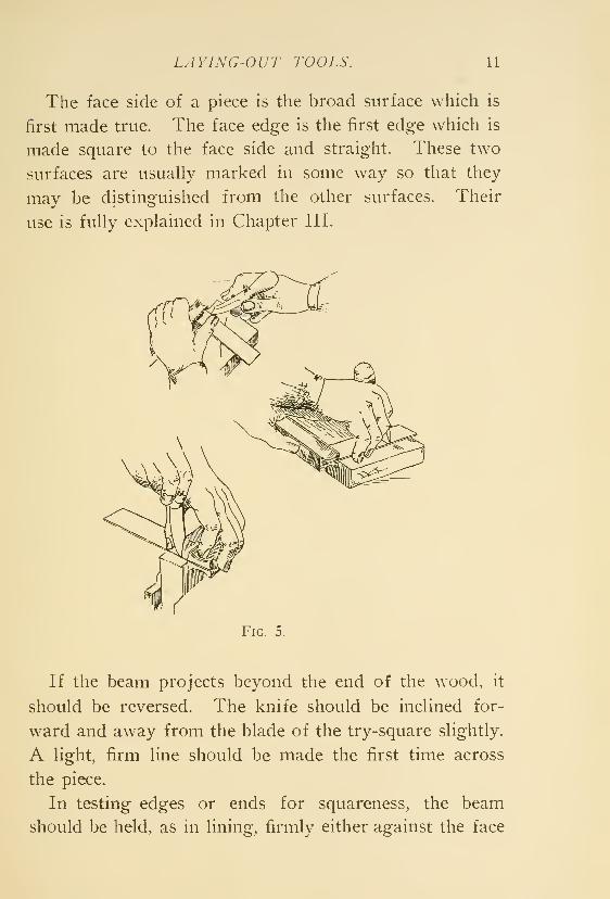
Fig. 5 shows the various positions assumed in lining
across a piece. The beam should be held firmly against
either the face side or the face edge.
LAYING-OUT TOOLS. 11
The face side of a piece is the broad surface which is
first made true. The face edge is the first edge which is
made square to the face side and straight. These two
surfaces are usually marked in some way so that they
may be distinguished from the other surfaces. Their
use is fully explained in Chapter III.
Fig. 5.
If the beam projects beyond the end of the wood, it
should be reversed. The knife should be inclined for-
ward and away from the blade of the try-square slightly.
A light, firm line should be made the first time across
the piece.
In testing edges or ends for squareness, the beam
should be held, as in lining, firmly either against the face
12 ESSENTIALS OF WOODWORKING.
side or the face edgfe. Fig. 6. Care should be taken to
test the extreme ends of the piece. Also test at a suffi-
cient number of points to show fully the condition of the
Fig. 6.
edge. Sliding the try-square along the edge is not ob-
jectionable if the blade be held lightly on the surface.
Under no circumstances should
the try-square be used to scrape
the wood.
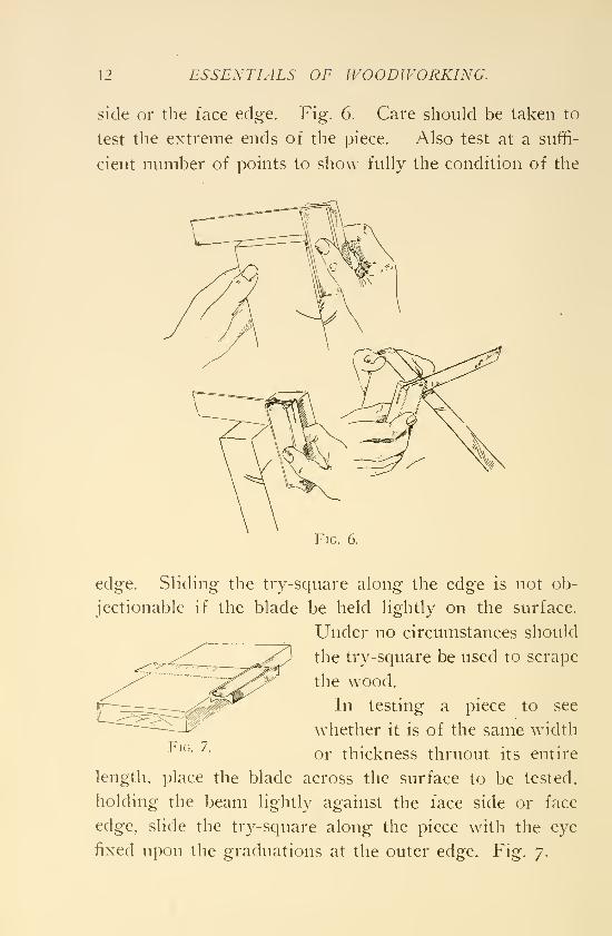
In testing a piece to see
whether it is of the same width
or thickness thruout its entire
length, place the blade across the surface to be tested,
holding the beam lightly against the face side or face
edge, slide the try-square along the piece with the eye
fixed upon the graduations at the outer edge. Fig. 7.
Fig. 7.
LAYING-OUT TOOLS. 13
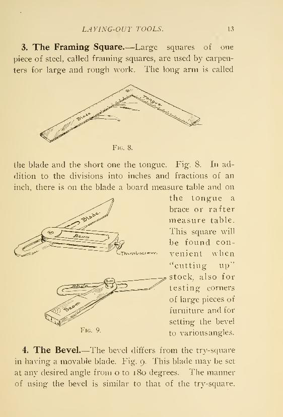
3. The Framing Square.—Large squares of one
piece of steel, called framing squares, are used by carpen-
ters for large and rough work. The long arm is called
Fig. 8.
the blade and the short one the tonsfue. Fig. 8. In ad-
dition to the divisions into inches and fractions of an
inch, there is on the blade a board measure table and on
the tongue a
brace or rafter
measure table.
This square will
be found con-
venient when"cutting up"
stock, also for
testing corners
of large pieces of
furniture and for
setting the bevel
to various angles.
TKum U 3<^r«= •»-<.
Fig. 9.
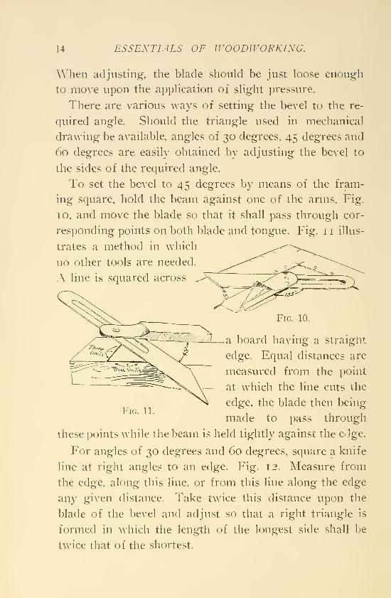
4. The Bevel.—The bevel differs from the try-square
in having a movable blade. Fig. 9. This blade may be set
at any desired angle from o to 180 degrees. The manner
of using the bevel is similar to that of the try-square.
14 ESSENTIALS OF WOODWORKING.
When adjusting, the blade should be just loose enough
to move upon the application of slight pressure.
There are various ways of setting the bevel to the re-
quired angle. Should the triangle used in mechanical
drawing be available, angles of 30 degrees, 45 degrees and
60 degrees are easily obtained by adjusting the bevel to
the sides of the required angle.
To set the bevel to 45 degrees by means of the fram-
ing square, hold the beam against one of the arms. Fig.
10, and move the blade so that it shall pass through cor-
responding points on both blade and tongue. Fig. 1 1 illus-
trates a method in which
no other tools are needed.
A line is squared across ^^s. ^^^'33>— - ^^
Fig. 11.
Fig. 10.
a board having a straight
edge. Equal distances are
measured from the point
at which the line cuts the
edge, the blade then being
made to pass through
these points while the beam is held tightly against the edge.
For angles of 30 degrees and 60 degrees, square a knife
line at right angles to an edge. Fig. 12. Measure from
the edge, along this line, or from this line along the edge
any given distance. Take twice this distance upon the
blade of the bevel and adjust so that a right triangle is
formed in which the length of the longest side shall be
twice that of the shortest.
LAYING-OUT TOOLS. 15
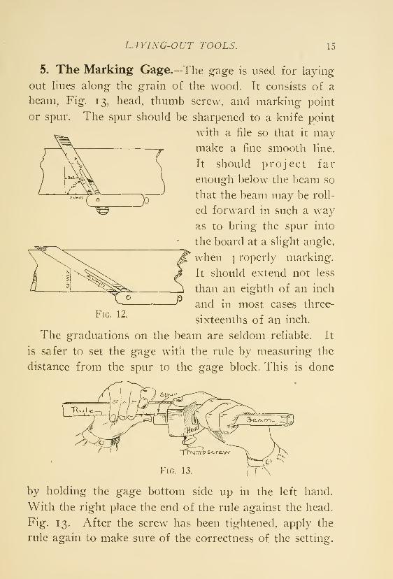
5. The Marking Gage.—The gage is used for laying
out lines along the grain of the wood. It consists of a
beam, Fig. 13, head, thumb screw, and marking point
or spur. The spur should be sharpened to a knife point
with a file so that it maymake a fine smooth line.
It should project far
enough below the beam so
that the beam may be roll-
ed forward in such a way
as to bring the spur into
the board at a slight angle,
when ] roperly marking.
It should extend not less
than an eighth of an inch
and in most cases three-
sixteenths of an inch.
The graduations on the beam are seldom reliable. It
is safer to set the gage wath the rule by measuring the
distance from the spur to the gage block. This is done
Fig. 12.
Fig. 13.
by holding the gage bottom side up in the left hand.
With the right place the end of the rule against the head.
Fig. 13. After the screw has been tightened, apply the
rule again to make sure of the correctness of the setting.
16 ESSENTIALS OF WOODWORKING.
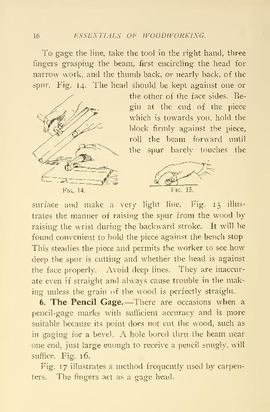
To gage the line, take the tool in the right hand, three
fingers grasping the beam, first encircling the head for
narrow work, and the thumb back, or nearly back, of the
spur. Fig. 14. The head should be kept against one or
the other of the face sides. Be-
gin at the end of the piece
which is towards you, hold the
block firmly against the piece,
roll the beam forward until
the spur barely touches the
Fig. 14. Fig. 15.
Fig. 15 illus-surface and make a very light line,
trates the manner of raising the spur from the wood by
raisinof the wrist durinjj the backward stroke. It will be
found convenient to hold the piece against the bench stop
This steadies the piece and permits the worker to see how
deep the spur is cutting and whether the head is against
the face properly. Avoid deep lines. They are inaccur-
ate even if straight and always cause trouble in the mak-
ing unless the grain of the wood is perfectly straight.
6. The Pencil Gage.—There are occasions when a
pencil-gage marks with sufficient accuracy and is more
suitable because its point does not cut the wood, such as
in gaging for a bevel. A hole bored thru the beam near
one end, just large enough to receive a pencil snugly, will
suffice. Fig. 16.
Fig. 17 illustrates a method frequently used by carpen-
ters. The fingers act as a gage head.
LAYING-OUT TOOLS. 17
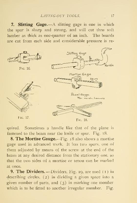
A. slitting gage is one in which7. Slitting Gage.
the spur is sharp and strong, and will cut thru soft
lumber as thick as one-quarter of an inch. The boards
are cut from each side and considerable pressure is re-
^^litTinq G^-g*
Fig. 16.
AnMe
NorTise Gd-qe-
Fig. 17.Fig. 18.
quired. Sometimes a handle like that of the plane is
fastened to the beam near the knife or spur. Fig. i8.
8. The Mortise Gauge.—Fig. i8 also shows a mortise
gage used in advanced work. It has twu spurs, one of
them adjusted by means of the screw at the end of the
beam at any desired distance from the stationary one, so
that the two sides of a mortise or tenon can be marked
at once.
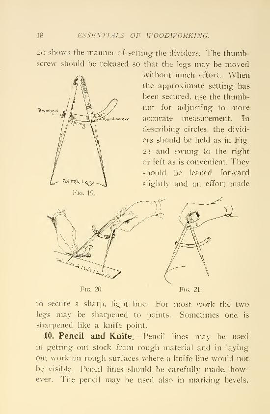
9. The Dividers.—Dividers, Fig. 19, are used (i) in
describing circles, (2) in dividing a given space into a
given number of parts, and (3) in marking one member
which is to be fitted to another irregular member. Fig.
18 ESSEXTIALS OF WOODWORKING.
Tnvmbnut
20 shows the manner of setting the dividers. The thumb-
screw should be released so that the legs may be moved
without much effort. Whenthe approximate setting has
been secured, use the thumb-
nut for adjusting to more
accurate measurement. In
describing circles, the divid-
ers should be held as in Fig.
21 and swung to the right
or left as is convenient. They
should be leaned forward
slightly and an effort made
Fig. 20. Fig. 21.
to secure a sharp, light line. For most work the two
legs may be sharpened to points. Sometimes one is
sharpened like a knife point.
10. Pencil and Knife.—Pencil lines may be used
in getting out stock from rough material and in laying
out work on rough surfaces where a knife line would not
be visible. Pencil lines should be carefully made, how-ever. The pencil may be used also in marking bevels.
LAYING-OUT TOOLS. 19
curves and in other places where the knife or gage mark
would be injurious. Otherwise, the knife and gage should
be used. Pencil lines are easiest removed from wood by
means of the eraser.
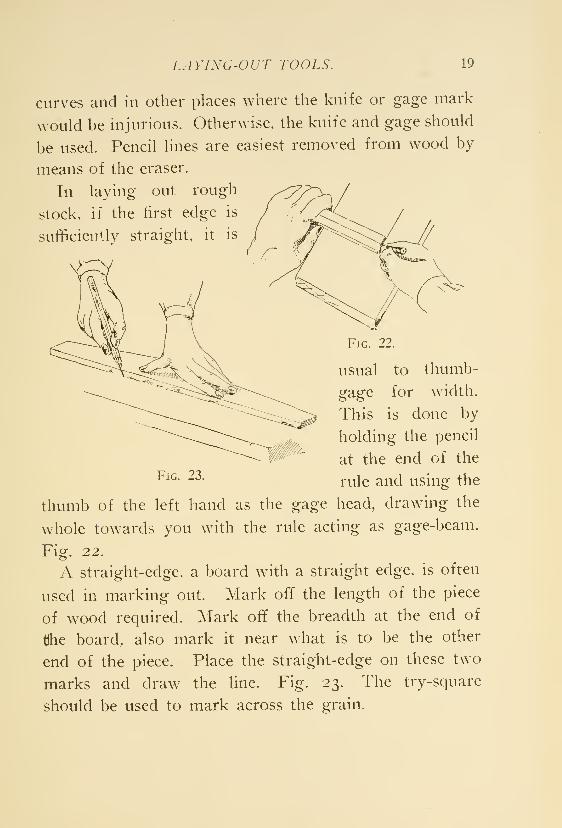
In laying out rough
stock, if the first edge is
sufficiently straight, it is
thumb-
width.
Fig. 23.
/Fig. 22.
usual to
gage for
This is done by
holding the pencil
at the end of the
rule and using the
thumb of the left hand as the gage head, drawing the
whole towards you with the rule acting as gage-beam.
Fig. 22.
A straight-edge, a board with a straight edge, is often
used in marking out. Mark off the length of the piece
of wood required. Mark off the breadth at the end of
tjhe board, also mark it near what is to be the other
end of the piece. Place the straight-edge on these two
marks and draw the line. Fig. 23. The try-square
should be used to mark across the grain.
CHAPTER 11.
Saws.
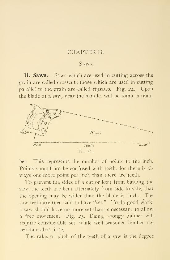
11. Saws.—Saws which are used in cutting across the
grain are called crosscut ; those which are used in cutting
parallel to the grain are called ripsaws. Fig. 24. Upon
the blade of a saw, near the handle, will be found a num-
/Yee/ ThinTT
ber. This represents the number of points to the inch.
Points should not be confused with teeth, for there is al-
ways one more point per inch than there are teeth.
To prevent the sides of a cut or kerf from binding the
saw, the teeth are bent alternately from side to side, that
the opening may be wider than the blade is thick. The
saw teeth are then said to have ''set." To do good work,
a saw should have no more set than is necessary to allow
a free movement. Fig. 25. Damp, spongy lumber will
require considerable set, while well seasoned lumber ne-
cessitates but little.
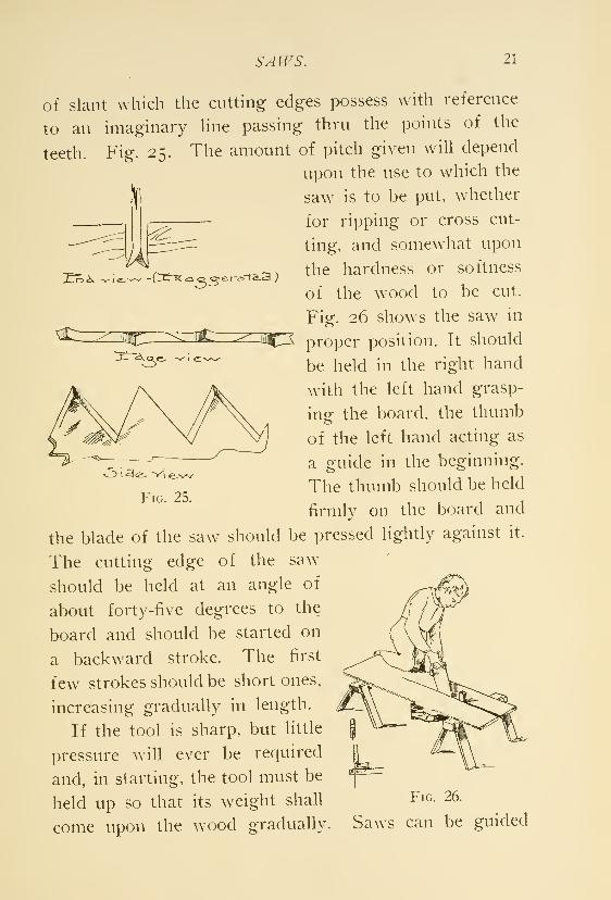
The rake, or ])itch of the teeth of a saw is the degree
SAWS. 21
E^^ (^£^ '3S e.r"«>~t^cd )
^^fcl^^i^Z HL;
"x- 1̂5^
of slant which the cutting edges possess with reference
to an imaginary hne passing thru the points of the
teeth. Fig. 25. The amount of pitch given will depend
upon the use to which the
saw is to be put, whether
for ripping or cross cut-
ting, and somewhat upon
the hardness or softness
of the wood to be cut.
Figf. 26 shows the saw in
^2 proper position. It should
be held in the right hand
with the left hand grasp-
ing the board, the thumb
of the left hand acting as
a guide in the beginning.
The thumb should be held
firmly on the board and
the blade of the saw should be pressed lightly against it.
The cutting edge of the saw
should be held at an angle of
about forty-five degrees to the
board and should be started on
a backward stroke. The first
few strokes should be short ones,
increasing gradually in length.
If the tool is sharp, but little
pressure will ever be recpiired
and, in starting, the tool must be
held up so that its weight shall
come upon the wood gradually.
Fig. 26.
Saws can be guided
21 ESSENTIALS OF WOODWORKING.
better if the index finger of the right hand is allowed to
extend along the side of the handle. Test occasionally,
sighting down the saw blade to see that the sides of the
saw are at right angles to the surface of the board. Atry-square may be used by the beginner, as shown in
Fig. 26.
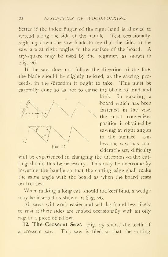
If the saw does not follow the direction of the line,
the blade should be slightly twisted, as the sawing pro-
ceeds, in the direction it ought to take. This must be
carefully done so as not to cause the blade to bind and
kink. In sawins; a
'board which has been
fastened in the vise,
the most convenient
position is obtained by
sawing at right angles
to the surface. Un-
less the saw has con-
siderable set, difficulty
will be experienced in changing the direction of the cut-
ting should this be necessary. This may be overcome by
lowering the handle so that the cutting edge shall make
the same angle with the board as when the board rests
on trestles.
When making a long cut, should the kerf bind, a wedge
may be inserted as shown in Fig. 26.
All saws will w^ork easier and will be found less likely
to rust if their sides are rubbed occasionally with an oily
rag or a piece of tallow.
12. The Crosscut Saw.—Fig. 25 shows the teeth of
a crosscut saw. This saw is filed so that the cutting
SAWS. 23
Ai
-^ 15^
Fig. 28.
edges are on the sides of the teeth. Every tooth is sharp-
ened to a point, one on the right side, the next on the left,
giving two parallel lines of sharp points with a V-shaped
groove between.
The pitch given the teeth of a crosscut saw will vary
with the hardness or softness of the wood which is to be
cut. For all-around use the amount of slant is about
one-third of the whole tooth. Fig. 2y.
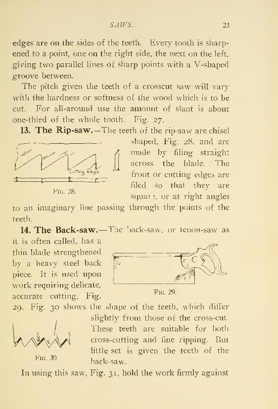
13. The Rip-saw.—The teeth of the rip-saw are chisel
shaped. Fig. 28, and are
/ made by filing straight
across the blade. The
front or cutting edges are
filed so that they are
squar ^ or at right angles
to an imaginary line passing through the points of the
teeth.
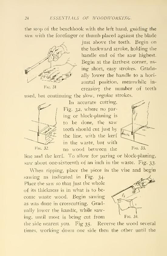
14. The Back-saw.—The '>ack-saw, or tenon-saw as
it is often called, has a
thin blade strengthened
by a heavy steel back
piece. It is used upon
work requiring delicate,
accurate cutting, Fig.
29. Fig. 30 shows the shape of the teeth, which differ
slightly from those of the cross-cut.
These teeth are suitable for both
cross-cutting and fine ripping. But
little set is given the teeth of the
hack-saw.
Fig. 29.
Fig. 30.
In using this saw, Fig. 31, hold the work firmly against
24 ESSENTIALS OF WOODWORKING.
the stop of the benchhook with the left hand, guiding the
saw with the forefinger or thumb placed against the blade
just above the teeth. Begin on
the backward stroke, holding the
handle end of the saw highest.
Begin at the farthest corner, us-
ing short, easy strokes. Gradu-
ally lower the handle to a hori-
zontal position, meanwhile in-
creasin'^ the number of teeth
used, but continuing the slow, regular strokes.
In accurate cutting,
Fig. 32, where no par-
ing or block-planing is
to be done, the saw
teeth should cut just by
the line, with the kerf
in the waste, but with
no wood between the
line and the kerf. To allow for paring or block-planing,
saw about one-sixteeiith of an inch in the waste. Fig. 33.
When ripping, place the piece in the vise and begin
sawing as indicated in Fig. 34.
Place the saw so that just the whole
of its thickness is in what is to be-
come waste wood. Begin sawing
as was done in crosscutting. Grad-
ually lower the handle, while saw-
ing, until most is being cut from
the side nearest you. Fig 35. Reverse the wood several
times, working down one side then the other until the
Fig. 2)i.
Fig. 34.
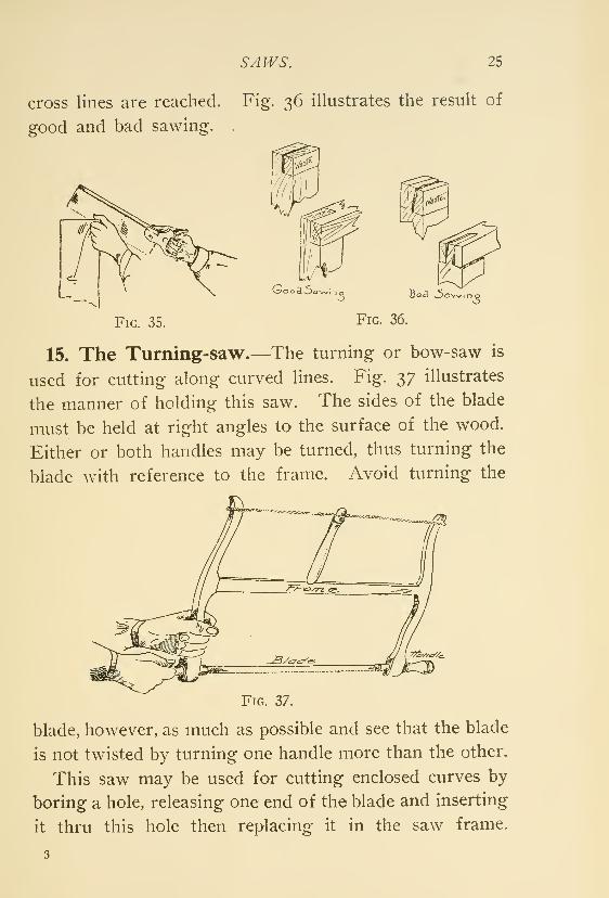
SAWS. 25
cross lines are reached. Fig. 36 illustrates the result of
good and bad sawing. .
(coo 3 s
Fig. 35. Fig. 36.
15. The Turning-saw.—The turning or bow-saw is
used for cutting along curved lines. Fig. 37 illustrates
the manner of holding this saw. The sides of the blade
must be held at right angles to the surface of the wood.
Either or both handles may be turned, thus turning the
blade with reference to the frame. Avoid turning the
Fig. 37.
blade, however, as much as possible and see that the blade
is not twisted by turning one handle more than the other.
This saw may be used for cutting enclosed curves by
boring a hole, releasing one end of the blade and inserting
it thru this hole then replacing it in the saw frame.
26 ESSENTIALS OF WOODWORKING.
Fig. 38.
As the cut of the turning saw is not very smooth, it is
advisable to leave about one-sixteenth of an inch between
the kerf and the line, to be removed later with the spoke-
shave.
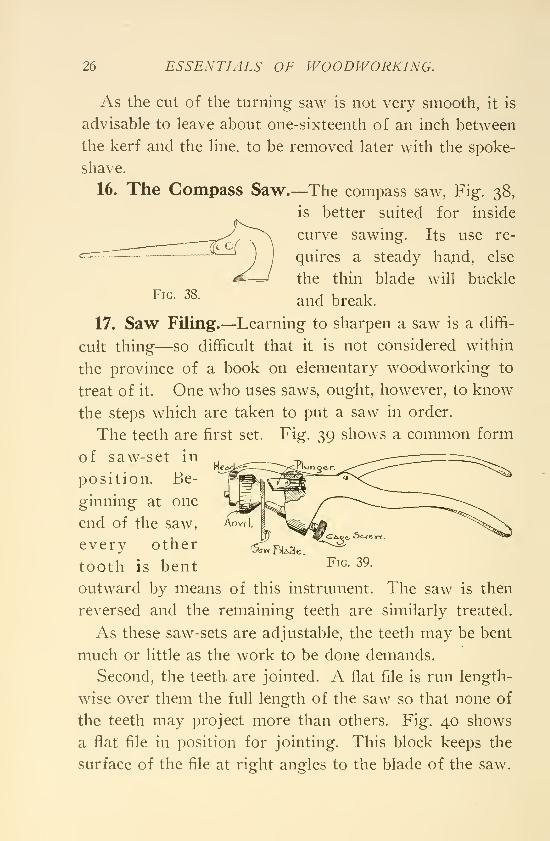
16. The Compass Saw.—The compass saw, Fig. 38,
is better suited for inside
curve sawing. Its use re-
quires a steady hand, else
the thin blade will buckle
and break.
17. Saw Filing.—Learning to sharpen a saw is a diffi-
cult thing—so difficult that it is not considered within
the province of a book on elementary woodworking to
treat of it. One who uses saws, ought, however, to know
the steps which are taken to put a saw in order.
The teeth are first set. Fig. 39 shows a common form
of saw-set in
position. Be-
ginning at one
end of the saw,
every other ^f>i^7^^'tooth is bent ^^^- ^^
outward by means of this instrument. The saw is then
reversed and the remaining teeth are similarly treated.
As these saw-sets are adjustable, the teeth may be bent
much or little as the work to be done demands.
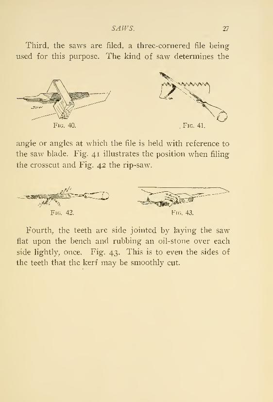
Second, the teeth are jointed. A flat file is run length-
wise over them the full length of the saw so that none of
the teeth may project more than others. Fig. 40 shows
a flat file in position for jointing. This block keeps the
surface of the file at right angles to the blade of the saw.
SAWS. 27
Third, the saws are filed, a three-cornered file being
used for this purpose. The kind of saw determines the
Fig. 40.,Fig. 41.
angle or angles at which the file is held with reference to
the saw blade. Fig. 41 illustrates the position when filing
the crosscut and Fig. 42 the rip-saw.
Fig. 43.
Fourth, the teeth are side jointed by laying the saw
flat upon the bench and rubbing an oil-stone over each
side lightly, once. Fig. 43. This is to even the sides of
the teeth that the kerf may be smoothly cut.
CHAPTER III.
Planes.
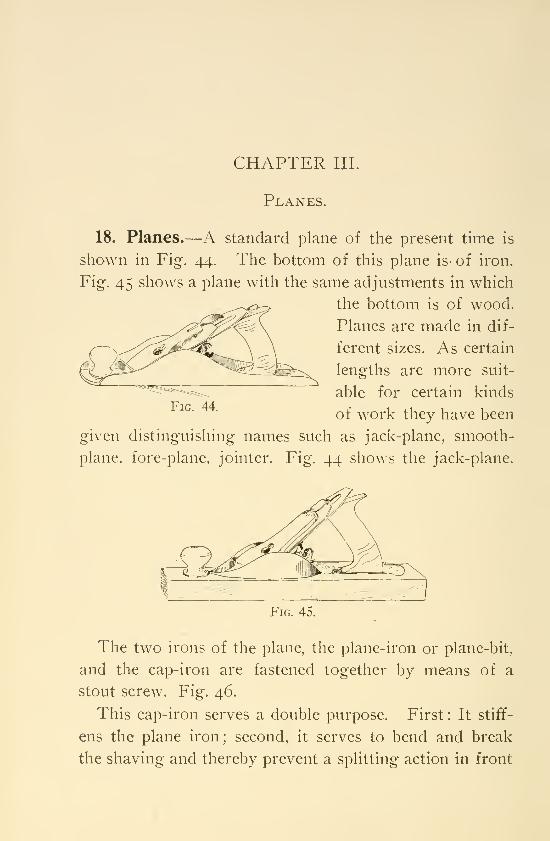
18. Planes.—A standard plane of the present time is
shown in Fig. 44. The bottom of this plane is- of iron.
Fig. 45 shows a plane with the same adjustments in which
the bottom is of wood.
Planes are made in dif-
ferent sizes. As certain
lengths are more suit-
able for certain kinds
of work they have been
given distinguishing names such as jack-plane, smooth-
plane, fore-plane, jointer. Fig, 44 shows the jack-plane.
Fig. 45.
The two irons of the plane, the plane-iron or plane-bit,
and the cap-iron are fastened together by means of a
stout screw. Fig. 46.
This cap-iron serves a double purpose. First : It stiff-
ens the plane iron ; second, it serves to bend and break
the shaving and thereby prevent a splitting action in front
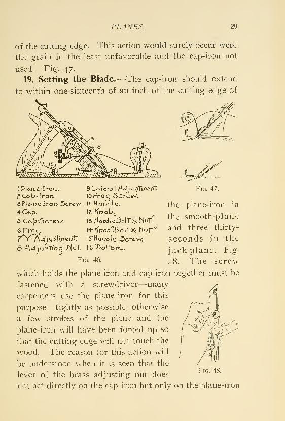
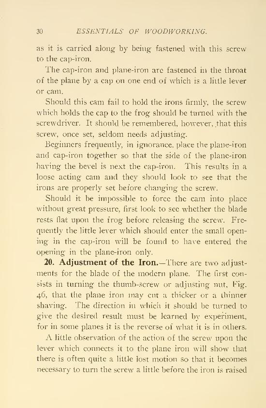
PLANES. 29
of the cutting edge. This action would surely occur were
the grain in the least unfavorable and the cap-iron not
used. Fig. 47.
19. Setting the Blade.—The cap-iron should extend
to within one-sixteenth of an inch of the cutting edge of
I P»6>ae-Iroa. 9 )_A.t«r<:« I AdJusTrpenT.£C6.|D-Iroa loFroQ 5crewr.
»3Pl6»ne-Iroo ^crew. il Handle.
AC&>\>. \% Kr7ob.
5 C<s )D-5crew. ) 5 KapJ I e.'3o It^. H< 'T.*
6 Fro3. )^ IVrvob'Boir^ MuK"T^'Y AdiustnoenlT l5"HaDdle ^crew.
Fig. 46.
Fig. 47.
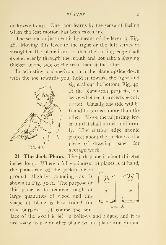
the plane-iron in
the smooth-plane
and three thirty-
seconds in the
jack-plane. Fig.
48. The screw
which holds the plane-iron and cap-iron together must be
fastened with a screwdriver—many
carpenters use the plane-iron for this
purpose—tightly as possible, otherwise
a few strokes of the plane and the
plane-iron will have been forced up so
that the cutting edge will not touch the
wood. The reason for this action will
be understood when it is seen that the
lever of the brass adjusting nut does
not act directly on the cap-iron but only on the plane-iron
Fig. 48.
30 ESSENTIALS OF WOODWORKING.
as it is carried along by being fastened with this screw
to the cap-iron.
The cap-iron and plane-iron are fastened in the throat
of the plane by a cap on one end of which is a little lever
or cam.
Should this cam fail to hold the irons firmly, the screw
which holds the cap to the frog should be turned with the
screwdriver. It should be remembered, however, that this
screw, once set, seldom needs adjusting.
Beginners frequently, in ignorance, place the plane-iron
and cap-iron together so that the side of the plane-iron
having the bevel is next the cap-iron. This results in a
loose acting cam and the}^ should look to see that the
irons are properly set before changing the screw.
Should it be impossible to force the cam into place
without great pressure, first look to see whether the blade
rests flat upon the frog before releasing the screw. Fre-
quently the little lever which should enter the small open-
ing in the cap-iron will be found to have entered the
opening in the plane-iron only.
20. Adjustment of the Iron.—There are two adjust-
ments for the blade of the modern plane. The first con-
sists in turning the thumb-screw or adjusting nut, Fig.
46, that the plane iron may cut a thicker or a thinner
shaving. The direction in which it should be turned to
give the desired result must be learned by experiment,
for in some planes it is the reverse of what it is in others.
A little observation of the action of the screw upon the
lever which connects it to the plane iron will show that
there is often quite a little lost motion so that it becomes
necessary to turn the screw a little before the iron is raised
PLANES. 31
—Ji
or lowered any. One soon learns by the sense of feeling
when the lost motion has been taken up.
The second adjustment is by means of the lever, 9, Fig.
46. Moving this lever to the right or the left serves to
straighten the plane-iron, so that the cutting edge shall
extend evenly through the mouth and not take a shaving
thicker at one side of the iron than at the other.
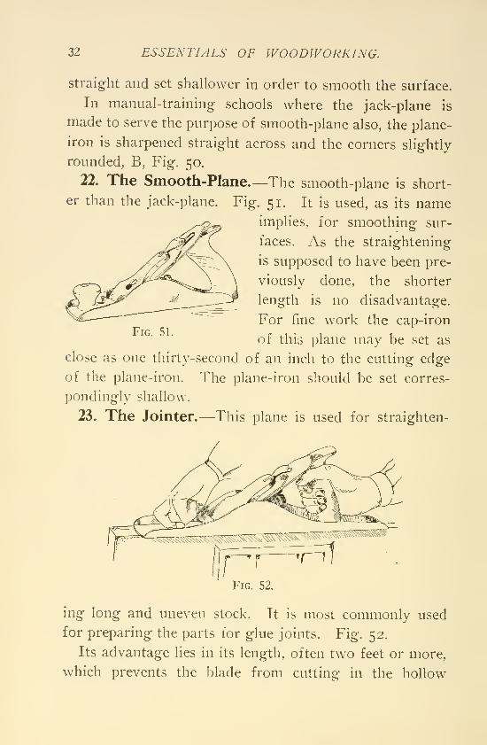
In adjusting a plane-iron, turn the plane upside down
with the toe towards you, hold it toward the light and
sight along the bottom, Fig. 49.
If the plane-iron projects, ob-
serve whether it projects evenly
or not. Usually one side will be
found to project more than the
other. Move the adjusting lev-
er until it shall project uniform-
ly. The cutting edge should
project about the thickness of a
piece of drawing paper for
average work.
21. The Jack-Plane.—The jack-plane is about thirteen
inches long. Where a full equipment of planes is at hand,
the plane-iron of the jack-plane is
ground slightly rounding as is
shown in Fig. 50 A. The purpose of
this plane is to remove rough or
large quantities of w^ood and this
shape of blade is best suited for
that purpose. Of course the sur-
face of the wood is left in hollows and ridges, and it is
necessary to use another plane with a plane-iron ground
Fig. 49.
fVi nsiE.
Fig. 50.
22 ESSENTIALS OF WOODWORKING.
Straight and set shallower in order to smooth the surface.
In manual-training schools where the jack-plane is
made to serve the purpose of smooth-plane also, the plane-
iron is sharpened straight across and the corners slightly
rounded, B, Fig. 50.
22. The Smooth-Plane.—The smooth-plane is short-
er than the jack-plane. Fig. 51. It is used, as its nameimplies, for smoothing sur-
faces. As the straightening
is supposed to have been pre-
viously done, the shorter
length is no disadvantage.
For fine work the cap-iron
of thi;5 plane may be set as
close as one thirty-second of an inch to the cutting edge
of the plane-iron. The plane-iron should be set corres-
pondingly shallow.
23. The Jointer.—This plane is used for straighten-
FiG. 51.
ing long and uneven stock. It is most commonly used
for preparing the parts for glue joints. Fig. 52.
Its advantage lies in its length, often two feet or more,
which prevents the blade from cutting in the hollow
PLANES. 33
places until all of the high places have been leveled. Ashort plane would simply follow the irrgularities, smooth-
ing but not straightening. The plane-iron of the jointer
should be ground straight across.
Fore-planes are short jointers, next in size to the jack-
planes, and are used for such work as straightening the
edges of doors, windows, etc., when fitting them.
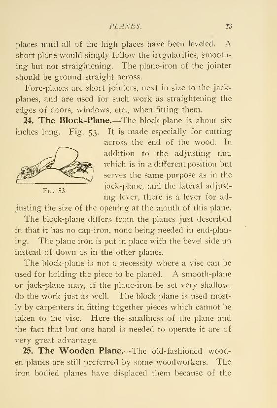
24. The Block-Plane.—The block-plane is about six
inches long. Fig. 53. It is made especially for cutting
across the end of the wood. In
addition to the adjusting nut,
which is in a different position but
serves the same purpose as in the
^ ,^ jack-plane, and the lateral adjust-FiG. 53.
. . . .
ing lever, there is a lever for ad-
justing the size of the opening at the mouth of this plane.
The block-plane differs from the planes just described
in that it has no cap-iron, none being needed in end-plan-
ing. The plane iron is put in place with the bevel side up
instead of down as in the other planes.
The block-plane is not a necessity where a vise can be
used for holding the piece to be planed. A smooth-plane
or jack-plane may, if the plane-iron be set very shallow,
do the work just as well. The block-plane is used most-
ly by carpenters in fitting together pieces which cannot be
taken to the vise. Here the smallness of the plane and
the fact that but one hand is needed to operate it are of
very great advantage.
25. The Wooden Plane.—The old-fashioned wood-
en planes are still preferred by some woodworkers. The
iron bodied planes have displaced them because of the
34 ESSENTIALS OF WOODWORKING.
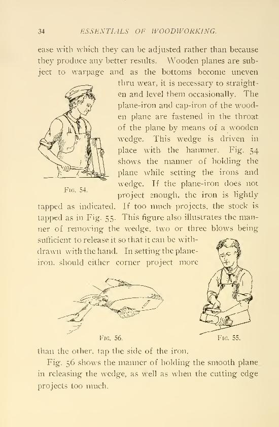
ease with which they can be adjusted rather than because
they produce any better results. Wooden planes are sub-
ject to warpage and as the bottoms become uneven
thru wear, it is necessary to straight-
en and level them occasionally. The
plane-iron and cap-iron of the wood-
en plane are fastened in the throat
of the plane by means of a wooden
wedge. This wedge is driven in
place with the hammer. Fig. 54
shows the manner of holding the
plane while setting the irons and
wedge. If the plane-iron does not
project enough, the iron is lightly
tapped as indicated. If too much projects, the stock is
tapped as in Fig. 55. This figure also illustrates the man-
ner of removing the wedge, two or three blows being
sufficient to release it so that it can be with-
drawn with the hand. In setting the plane-
iron, should either corner project more
Fig. 54.
Fig. 56. Fig. 55.
than the other, tap the side of the iron.
Fig. 56 shows the manner of holding the smooth plane
in releasing the wedge, as well as when the cutting edge
projects too much.
PLANES. 35
26. Planing First Surface True.—A true surface is
one which is straight as to its length and width and
which has its surface at the four corners in the same plane.
Select for this first surface, which we shall call the face
side, the better of the two broad surfaces. Knots, sap,
wind, shakes, etc., should there be any, must be taken into
Fig. 57.
account when passing judgment. Often the two sides are
so nearly alike that there is little reason for choice.
Where several parts are to be fitted together, the faces
are turned in ; in this case, the best surfaces should not be
selected for faces. Chapter VII, section 75.
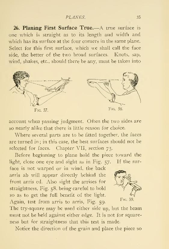
Before beginning to plane hold the piece toward the
light, close one eye and sight as in Fig. 57. If the sur-
face is not warped or in wind, the back
arris ab will appear directly behind the
front arris cd. Also sight the arrises for
straightness, Fig. 58, being careful to hold
so as to get the full benefit of the light.
Again, test from arris to arris, Fig. 59.
The try-square may be used either side up, but the beam
must not be held against either edge. It is not for square-
ness but for straightness that this test is made.
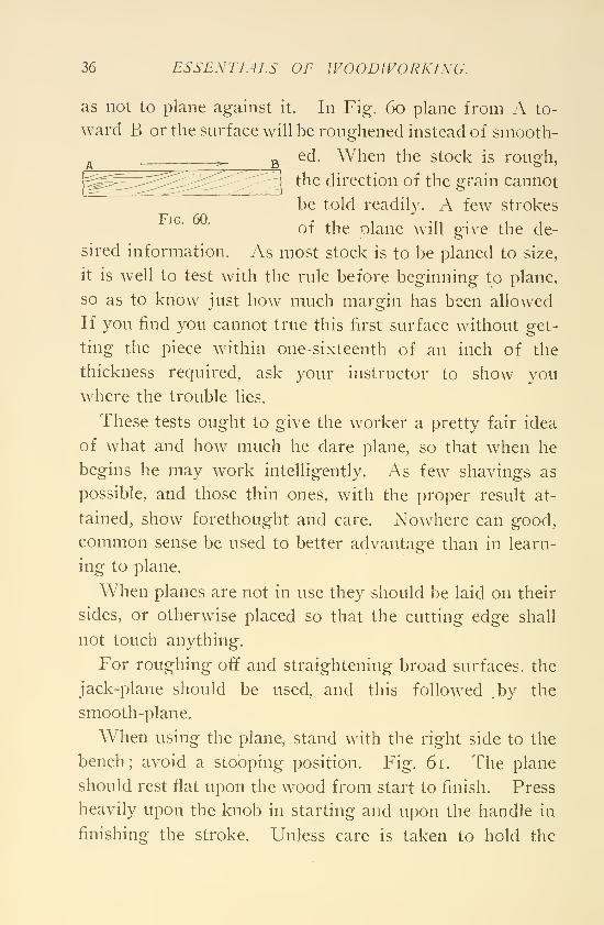
Notice the direction of the grain and place the piece so
Fig. 59.
36 ESSENTIALS OF WOODWORKING.
as not to plane against it. In Fig. 60 plane from A to-
ward B or the surface will be roughened instead of smooth-
ed. When the stock is rough,
the direction of the grain cannot
be told readily. A few strokes
of the olane will give the de-
sired information. As most stock is to be planed to size,
it is well to test with the rule before beginning to plane,
so as to know just how much margin has been allowed
If you find you cannot true this first surface without get-
ting the piece within one-sixteenth of an inch of the
thickness required, ask your instructor to show you
where the trouble lies.
These tests ought to give the worker a pretty fair idea
of what and how much he dare plane, so that when he
begins he may work intelligently. As few shavings as
possible, and those thin ones, with the proper result at-
tained, show forethought and care. Nowhere can good,
common sense be used to better advantage than in learn-
ing to plane.
When planes are not in use they should be laid on their
sides, or otherwise placed so that the cutting edge shall
not touch anything.
For roughing ofT and straightening broad surfaces, the
jack-plane should be used, and this followed .by the
smooth-plane.
When using the plane, stand with the right side to the
bench; avoid a stooping position. Fig. 61. The plane
should rest flat upon the wood from start to finish. Press
heavily upon the knob in starting and upon the handle in
finishing the stroke. Unless care is taken to hold the
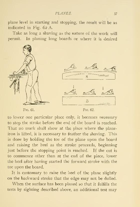
PLANES. 37
plane level in starting and stopping, the result will be as
indicated in Fig. 62 A.
Take as long a shaving as the nature of the work will
permit. In planing long boards or where it is desired
B
Fig. 61. Fig. 62.
to lower one particular place only, it becomes necessary
to stop the stroke before the end of the board is reached.
That no mark shall show at the place where the plane-
iron is lifted, it is necessary to feather the shaving. This
is done by holding the toe of the plane upon the board
and raising the heel as the stroke proceeds, beginning
just before the stopping point is reached. If the cut is
to commence other than at the end of the piece, lower
the heel after having started the forward stroke with the
toe upon the board.
It is customary to raise the heel of the plane slightly
on the backward stroke that the edge may not be dulled.
When the surface has been planed so that it fulfills the
tests by sighting described above, an additional test may
38 ESSENTIALS OF WOODWORKING.
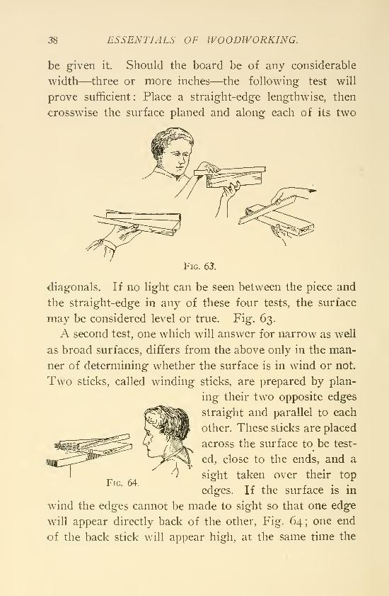
be given it. Should the board be of any considerable
width—three or more inches—the following test will
prove sufficient: Place a straight-edge lengthwise, then
crosswise the surface planed and along each of its two
Fig. 63'.
diagonals. If no light can be seen between the piece and
the straight-edge in any of these four tests, the surface
may be considered level or true. Fig. 63.
A second test, one which will answer for narrow as well
as broad surfaces, differs from the above only in the man-
ner of determining whether the surface is in wind or not.
Two sticks, called winding sticks, are prepared by plan-
ing their two opposite edges
straight and parallel to each
other. These sticks are placed
across the surface to be test-
ed, close to the ends, and a
sight taken over their top
edges. If the surface is in
wind the edges cannot be made to sight so that one edge
will appear directly back of the other, Fig. 64; one end
of the back stick will appear high, at the same time the
Fig. 64.
PLANES. 39
Other one will appear low with reference to the edge of
the fore stick. The back corner is high only as compared
with the fore corner. The wind may be taken out of the
surface just as well by planing the fore corner which is
diagonally opposite. Usually, equal amounts should be
planed from the surface at each of these corners. If,
however, the board is thicker at one corner than the other,
it is best to take the whole amount at the thicker corner.
27. Face Side, Face Edge.—The first surface and the
first edge planed serve a special purpose and are given
special names. The first surface is called the face side,
and the first edge, the face edge ; both may be referred to
as the faces. These faces are sometimes known by other
names such as working face
and joint edge, marked face
and marked edge, etc., but their
meaning is the same.
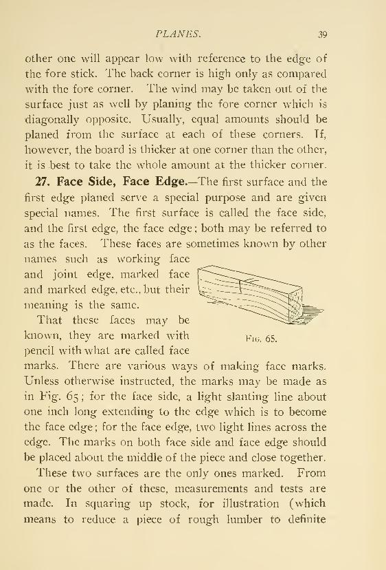
That these faces may be
known, they are marked with ^ig. 65.
pencil with what are called face
marks. There are various ways of making face marks.
Unless otherwise instructed, the marks may be made as
in Fig. 65 ; for the face side, a light slanting line about
one inch long extending to the edge which is to become
the face edge ; for the face edge, two light lines across the
edge. The marks on both face side and face edge should
be placed about the middle of the piece and close together.
These two surfaces are the only ones marked. Fromone or the other of these, measurements and tests are
made. In squaring up stock, for illustration (which
means to reduce a piece of rough lumber to definite
40 ESSENTIALS OF WOODWORKING.
length, width and thickness so that it shall have smooth,
flat sides at right angles to each other) the gage block is
held against one or the other of these faces only, and the
beam of the try-square when testing for squareness is
placed against one or the other of these faces only.
28. Planing First Edge Square with Face Side.—
Make a preliminary test with the eye before beginning to
plane. Sight the arrises of the edge to see where it needs
straightening. Examine the end to see which arris is
high. Also look to see which way the grain runs. Avoid
imperfections in the wood as far as possible in choosing
this edge.
It is the part of wisdom to examine the plane-iron to
see that the surface planing has not caused the cutting
edge to project unevenly. A plane, set out of true, is
likely to cause hours of extra work ; it defeats every effort
that may be made to hold the plane properly.
Strive to get shavings the full length of the piece, es-
pecially on the last few strokes.
The smooth-plane is little if ever used for edge planing
on account of its short length. In using the jack-plane?
in which the edge is slightly rounded, thus making a shav-
ing thicker in the middle than at the edges, avoid tilting
the plane to make it cut on one side rather than the other.
Move the whole plane over to the high side so that the
middle of the cutting edge shall be directly over the high
place. Keep the sides of the plane parallel with the edge
so as to get the full benefit of the length of the plane.
The two tests which this first edge must fulfill are:
First, that it shall be straight; second, that it shall be
square with the face side. Fig. 6, Chapter I, shows the
PLANES. 41
method of testing for squareness. As in planing the face
side, try to accomplish the desired result with as few
shavings as possible.
The caution about planing the first surface, where a
definite size is to be attained, applies equally to planing
the first edge.
When the edge has been properly trued, put on the face
marks suitable for the face edge.
29. Finishing the Second Edge.—A line gaged from
the face edge indicates the proper stopping place in plan-
ing the second edge. This line, if lightly made, should be
half planed off.
As the line is parallel with the face edge, no straight
edge test is necessary. The try-square test for square-
ness, the beam being held against the face side, must be
frequently applied when approaching the gage line.
Where the amount of waste stock to be planed is about
an eighth of an inch, the plane-iron may be set a little
deeper than average. When near the line, however, it
must be set quite shallow. If the waste stock measures
more than three sixteenths of an inch, the rip-saw should
be used, sawing parallel to the gage line and about one-
eighth of an inch away from it.
30. Finishing the Second Side.—Lines gaged from
the face side on the two edges show the amount to be
planed.
The test for this side is made by placing the straight-
edge across the piece from arris to arris as the planing
proceeds, to see that the middle shall be neither high nor
low when the gage lines have been reached. No other
test is necessary; a little thought will show the reason.
42 ESSENTIALS OF WOODWORKING.
Never attempt to work without lines. If by mistake
you plane out your line, take the piece to your instructor
at once, unless you have been otherwise directed, that he
may tell you what to do.
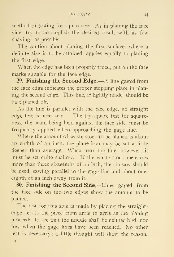
31. Planing the First End Square.—See that the cut-
ting edge is very sharp and that the plane-iron is set per-
fectly true and very shallow. Examine one of the ends
of the piece by placing the beam of the try-square against
the face side then against face edge to locate the high
places. Fig. 6.
In free end planing, the cutting edge must not be allow-
ed to reach the farther corner or the corner will be broken
Stop
II
\
Fig. 66.
\ \
off. Plane only part way across the end, stopping the cut-
ting edge half an inch or more from the far edge. Fig.
66. After a few strokes in this direction, reverse the posi-
tion and plane in the opposite direction, stopping the cut-
ting edge half an inch or more of the first edge.
Keep testing the end as the planing proceeds that you
may know what you are doing. Remove no more material
than is necessary to square the end, and lay on the rule
occasionally that you may not endanger the correct length
in your efforts to square this end.
32. Finishing the Second End.—Knife lines squared
entirely around the piece, at a given distance from the end
first squared, limit the amount of the planing that can be
PLANES. 43
Fig. 67.
done on this end. If the waste stock is over one-eighth of
an inch the saw should be used to remove all but a thirty-
second of an inch before beginning to plane. Watch the
lines. If you are uncertain as to their accuracy, test this
end as you did the first one.
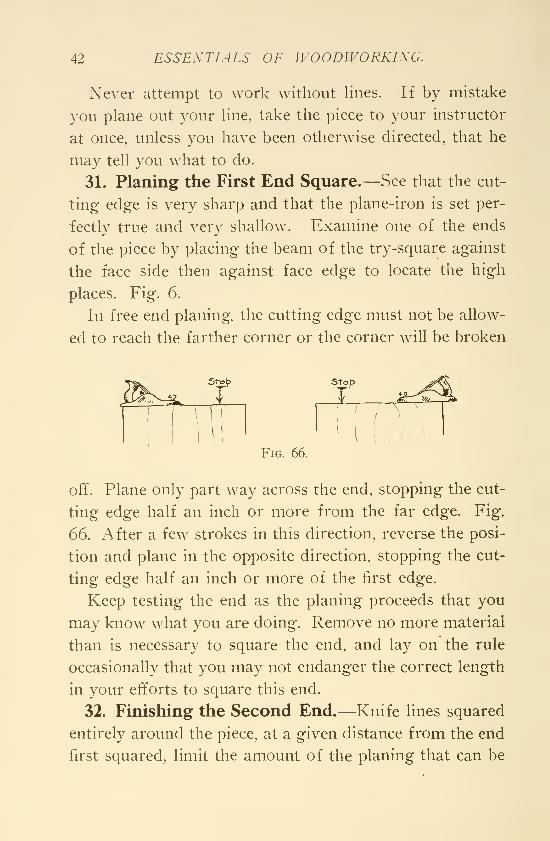
33. End Planing with the Shooting Board.—Fig. 67illustrates a way in which the
ends of narrow pieces may be
easily squared. The plane is
pressed to the shooting board
with the right hand. The left
hand holds the piece against
the stop and to the plane.
The face edge of the piece
should be held against the
stop; the wood must not be
allowed to project beyond the stop.
If it does, the corners, being unsup-
ported, will be broken away as in
free planing when the cutting edge
is accidentally shoved entirely across
the piece.
The bench hook makes an admir-
able shooting board. Fig. 68.
34. Rules for Planing to Dimensions.A True and smooth a broad surface; put on a face
mark. This becomes the face side.
2. Joint (straighten and square) one edge from the
face side;put on a face mark. This becomes the face edge.
3. Gage to required width from the face edge, and
joint to the gage line.
Fig. 68.
44 ESSENTIALS OF WOODWORKING.
4. Gage to required thickness on both edges from the
face side;plane to the gage lines.
5. Square one end from the face side and face edge.
6. Lay off with knife and square the required length
from the squared end ; saw to the knife line.
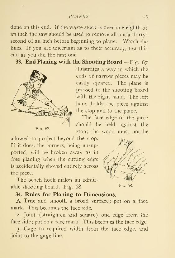
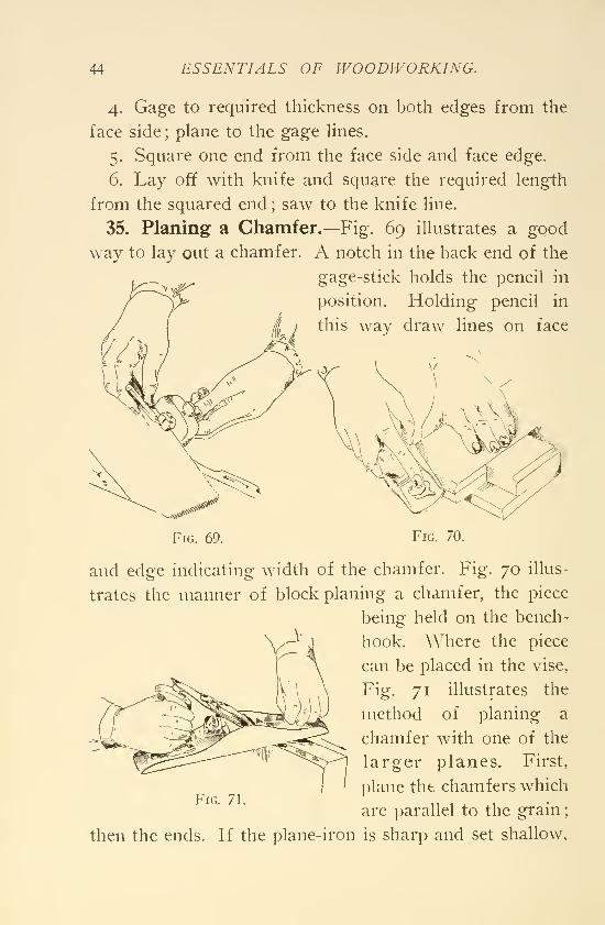
35. Planing a Chamfer.—Fig. 69 illustrates a good
way to lay out a chamfer. A notch in the back end of the
gage-stick holds the pencil in
position. Holding pencil in
this way draw lines on face
Fig. 69. Fig. 70.
and edge indicating width of the chamfer. Fig. 70 illus-
trates the manner of block planing a chamfer, the piece
being held on the bench-
hook. Where the piece
can be placed in the vise,
Fig. 71 illustrates the
method of planing a
chamfer with one of the
larger planes. First,
plane the chamfers which
are parallel to the grain
;
then the ends. If the plane-iron is sharp and set shallow,
Fig. 71.
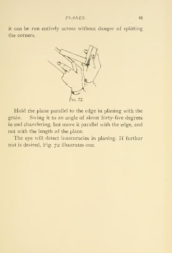
PLANES. 45
it can be run entirely across without danger of splitting
the corners.
Fig. 72.
Hold the plane parallel to the edge in planing with the
grain. Swing it to an angle of about forty-five degrees
in end chamfering, but move it parallel with the edge, and
not with the length of the plane.
The eye will detect inaccuracies in planing. If furthur
test is desired, Fig. 72 illustrates one.
CHAPTER IV.
Boring Tools—Boring.
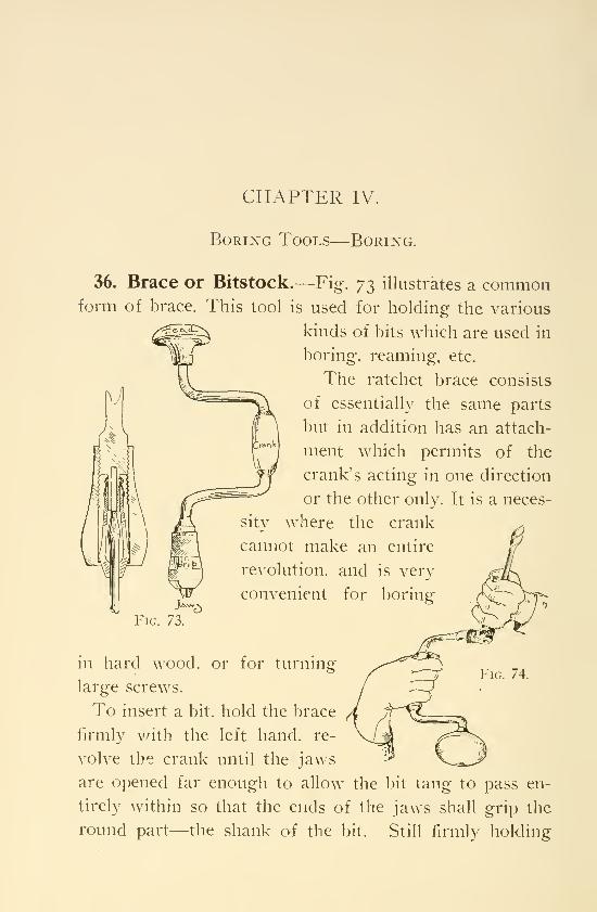
36. Brace or Bitstock.—Fig. 73 illustrates a commonform of brace. This tool is used for holding the various
kinds of bits which are used in
boring, reaming, etc.
The ratchet brace consists
of essentially the same parts
but in addition has an attach-
ment which permits of the
crank's acting in one direction
or the other only. It is a neces-
sity where the crank
cannot make an entire
revolution, and is very
convenient for boring
in hard wood, or for turning-
large screws.
To insert a bit. hold the brace
firmly with the left hand, re-
volve the crank until the jaws
are opened far enough to allow the bit tang to pass en-
tirely within so that the ends of the jaws shall grip the
round part—the shank of the bit. Still firmly holding
BORING TOOLS. A7
the brace, revolve the crank in the opposite direction until
the bit is firmly held. Fig. 74.
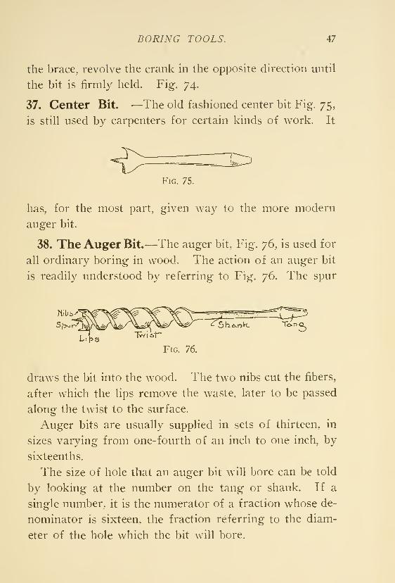
37. Center Bit. —The old fashioned center bit Fig. 75,
is still used by carpenters for certain kinds of work. It
Fig. 75.
has, for the most part, given way to the more modern
auger bit.
38. The Auger Bit.—The auger bit, Fig. y6, is used for
all ordinary boring in wood. The action of an auger bit
is readily understood by referring to Fig. 76. The spur
draws the bit into the wood. The tw^o nibs cut the fibers,
after which the lips remove the waste, later to be passed
along the twist to the surface.
Auger bits are usually supplied in sets of thirteen, in
sizes varying from one-fourth of an inch to one inch, by
sixteenths.
The size of hole that an auger bit will bore can be told
by looking at the number on the tang or shank. If a
single number, it is the numerator of a fraction whose de-
nominator is sixteen, the fraction referring to the diam-
eter of the hole which the bit will bore.
48 ESSENTIALS OF WOODWORKING.
Exercise care in laying down a bit ; it is easily dulled.
Do not use a good auger bit where there is any danger of
its striking nails or other metal.
x\uger bits are easily sharpened, a small file being used,
but they are more easily spoiled by improper filing, and
no student should attempt to sharpen one without having
personal direction from his instructor.
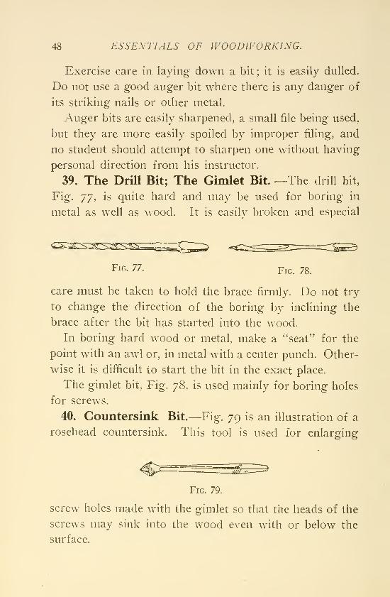
39. The Drill Bit; The Gimlet Bit. —The drill bit,
Fig. yy, is quite hard and may be used for boring in
metal as well as wood. It is easily broken and especial
Fig. 77. Fjg. 78.
care must be taken to hold the brace firmly. Do not try
to change the direction of the boring by inclining the
brace after the bit has started into the wood.
In boring hard wood or metal, make a ''seat" for the
point with an awl or, in metal with a center punch. Other-
wise it is difficult to start the bit in the exact place.
The gimlet bit, Fig. 78, is used mainly for boring holes
for screws.
40. Countersink Bit.—Fig. 79 is an illustration of a
rosehead countersink. This tool is used for enlarging
Fig. 79.
screw holes made with the gimlet so that the heads of the
screws may sink into the wood even with or below the
surface.
BORING TOOLS. 49
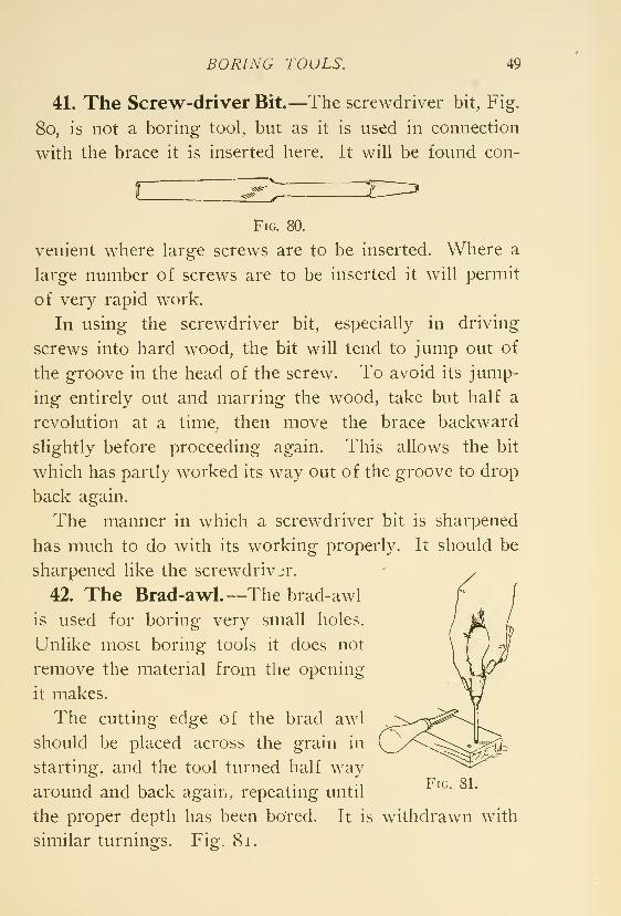
41. The Screw-driver Bit.—The screwdriver bit, Fig.
80, is not a boring tool, but as it is used in connection
with the brace it is inserted here. It will be found con-
FiG. 80.
venient where large screws are to be inserted. Where a
large number of screws are to be inserted it will permit
of very rapid work.
In using the screwdriver bit, especially in driving
screws into hard wood, the bit will tend to jump out of
the groove in the head of the screw. To avoid its jump-
ing entirely out and marring the wood, take but half a
revolution at a time, then move the brace backward
slightly before proceeding again. This allows the bit
which has partly worked its way out of the groove to drop
back again.
The manner in which a screwdriver bit is sharpened
has much to do with its working properly. It should be
sharpened like the screwdrivjr.
42. The Brad-awl.—The brad-awl
is used for boring very small holes.
Unlike most boring tools it does not
remove the material from the opening-
it makes.
The cutting edge of the brad awl
should be placed across the grain in
starting, and the tool turned half way
around and back again, repeating until
the proper depth has been bored. It is withdrawn with
similar turnings. Fig. 81.
Fig. 81.
50 ESSENTIALS OF WOODWORKING.
Patent spiral screwdrivers and automatic drills have
come into quite common use in recent years. They are
used mainly upon light work ; their advantage being the
rapidity with which they do their work.
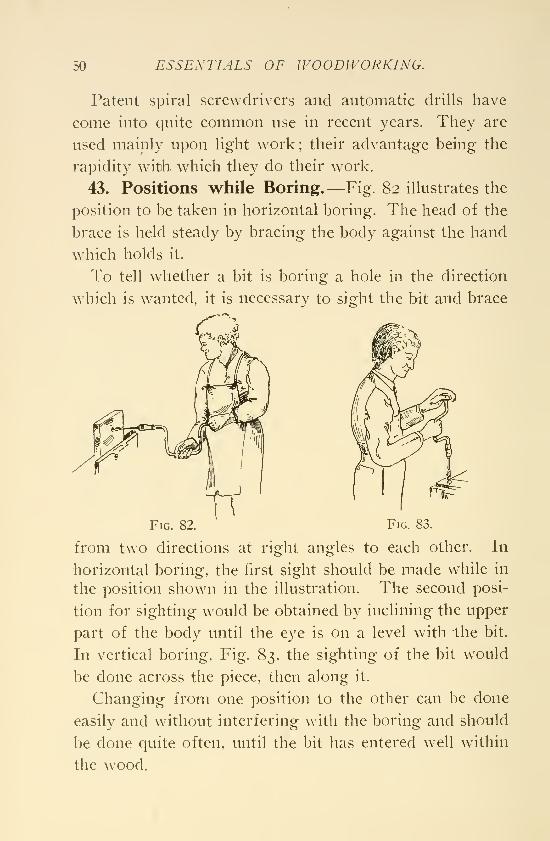
43. Positions while Boring.—Fig. 82 illustrates the
position to be taken in horizontal boring. The head of the
brace is held steady by bracing the body against the hand
which holds it.
To tell whether a bit is boring a hole in the direction
which is wanted, it is necessary to sight the bit and brace
Fig. 82. Fig. 83.
from two directions at right angles to each other. In
horizontal boring, the first sight should be made while in
the position shown in the illustration. The second posi-
tion for sighting would be obtained by inclining the upper
part of the body until the eye is on a level with the bit.
In vertical boring, Fig. 83, the sighting of the bit would
be done across the piece, then along it.
Changing from one position to the other can be done
easily and without interfering with the boring and should
be done quite often, until the bit has entered well within
the wood.
BORING TOOLS. 51
Fig. 84.
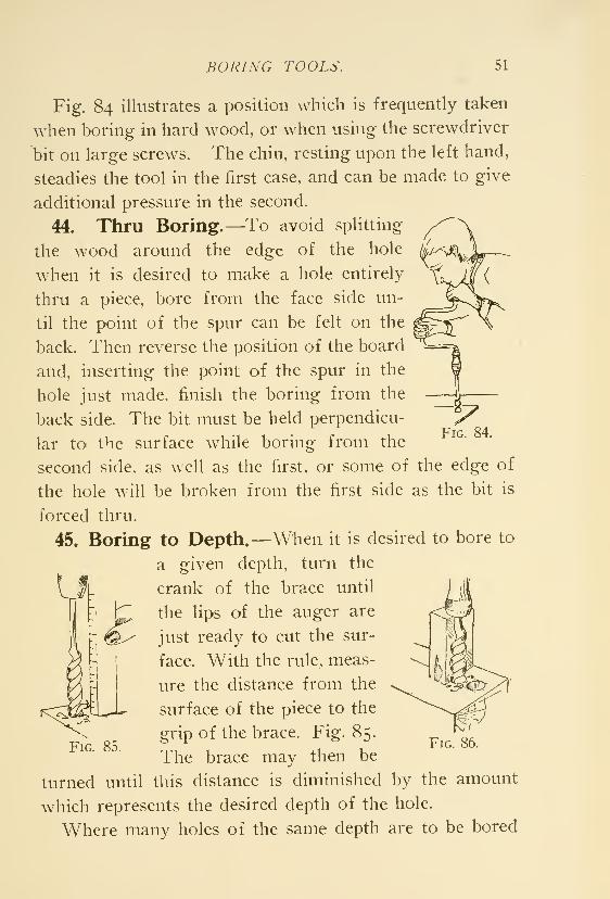
Fig. 84 illustrates a position which is frequently taken
when boring in hard wood, or when using the screwdriver
bit on large screws. The chin, resting upon the left hand,
steadies the tool in the first case, and can be made to give
additional pressure in the second.
44. Thru Boring.—To avoid splitting
the wood around the edge of the hole
when it is desired to make a hole entirely
thru a piece, bore from the face side un-
til the point of the spur can be felt on the
back. Then reverse the position of the board
and, inserting the point of the spur in the
hole just made, finish the boring from the
back side. The bit must be held perpendicu-
lar to the surface while boring from the
second side, as well as the first, or some of the edge of
the hole will be broken from the first side as the bit is
forced thru.
45. Boring to Depth.—When it is desired to bore to
a given depth, turn the
crank of the brace until
the lips of the auger are
just ready to cut the sur-
face. With the rule, meas-
ure the distance from the
surface of the piece to the
grip of the brace. Fig. 85.
The brace may then be
turned until this distance is diminished by the amount
which represents the desired depth of the hole.
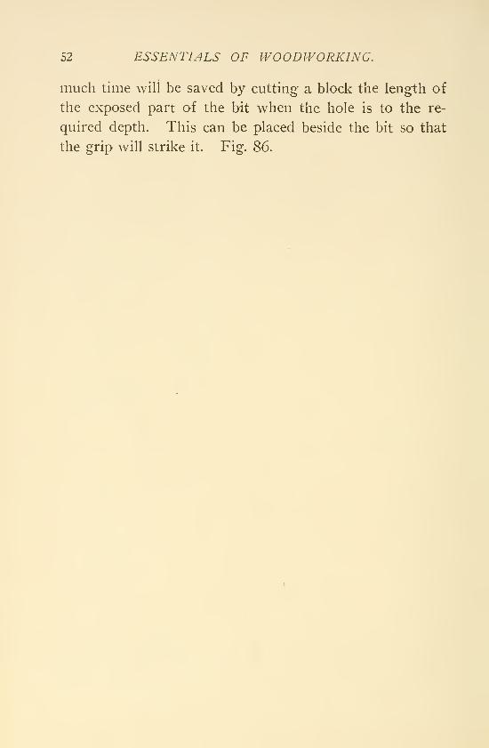
Where many holes of the same depth are to be bored
Fig. 85.
52 ESSENTIALS OF WOODWORKING.
much time will be saved by cutting a block the length of
the exposed part of the bit when the hole is to the re-
quired depth. This can be placed beside the bit so that
the grip will strike it. Fig. 86.
CHAPTER V.
Chisels and Chiseling.
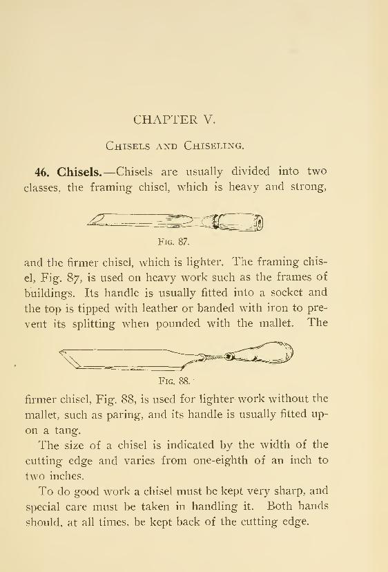
46. Chisels.—Chisels are usually divided into two
classes, the framing chisel, which is heavy and strong,
Fig. 87.
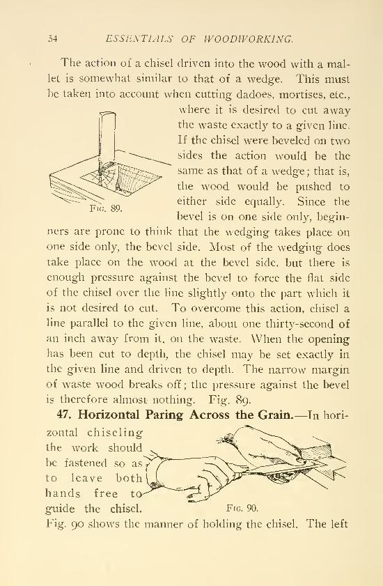
and the firmer chisel, which is lighter. The framing chis-
el, Fig. 87, is used on heavy work such as the frames of
buildings. Its handle is usually fitted into a socket and
the top is tipped with leather or banded with iron to pre-
vent its splitting when pounded with the mallet. The
Fig. 88.•
firmer chisel, Fig. 88, is used for lighter work without the
mallet, such as paring, and its handle is usually fitted up-
on a tang.
The size of a chisel is indicated by the width of the
cutting edge and varies from one-eighth of an inch to
two inches.
To do good work a chisel must be kept very sharp, and
special care must be taken in handling it. Both hands
should, at all times, be kept back of the cutting edge.
54 ESSENTIALS OF WOODWORKING.
Fig. 89.
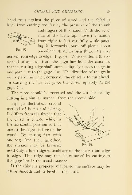
The action of a chisel driven into the wood with a mal-
let is somewhat similar to that of a wedge. This must
be taken into account when cutting dadoes, mortises, etc.,
where it is desired to cut awaythe waste exactly to a given line.
If the chisel were beveled on two
sides the action would be the
same as that of a wedge ; that is,
the wood would be pushed to
either side equally. Since the
bevel is on one side only, begin-
ners are prone to think that the wedging takes place on
one side only, the bevel side. Most of the wedging does
take place on the wood at the bevel side, but there is
enough pressure against the bevel to force the flat side
of the chisel over the line slightly onto the part which it
is not desired to cut. To overcome this action, chisel a
line parallel to the given line, about one thirty-second of
an inch away from it, on the waste. When the opening
has been cut to depth, the chisel may be set exactly in
the given line and driven to depth. The narrow margin
of waste wood breaks off; the pressure against the bevel
is therefore almost nothing. Fig. 89.
47. Horizontal Paring Across the Grain.—In hori-
zontal chiseling
the work should
be fastened so as y
to leave both
hands free to
guide the chisel. Fig. 90.
Fig. 90 shows the manner of holding the chisel. The left
CHISELS AND CHISELING. 55
Fig. 91.
hand rests against the piece of wood and the chisel is
kept from cutting too far by the pressuie of the thumb
and lingers of this hand. With the bevel
side of the blade up, move the handle
from right to left carefully while push-
ing it forwards;pare off pieces about
one-sixteenth of an inch thick half way
across from edge to edge. Fig. 91. When within a thirty-
second of an inch from the gage line hold the chisel so
that its cutting edge shall move obliquely across the grain
and pare just to the gage line. The direction of the grain
will determine which corner of the chisel is to cut ahead.
In starting the last cut place the chisel squarely fn the
gage line.
The piece should be reversed and the cut finished by
cutting in a similar manner from the second side.
Fig. 92 illustrates a second
method of horizontal paring.
It differs from the first in that
the chisel is turned while in
the horizontal position so that
one of the edges is free of the
wood. By cutting first with
one edge free, then the other,
the surface may be lowered ^^^- ^^•
until only a low ridge extends across the piece from edge
to edge. This ridge may then be removed by cutting to
the gage line in the usual manner.
If the chisel is properly sharpened the surface may be
left as smooth and as level as if planed.
56 ESSENTIALS OF WOODWORKING.
Fig. 93.
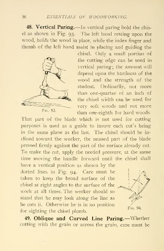
48. Vertical Paring.—In vertical paring hold the chis-
el as shown in Fig. 93. The left hand resting upon the
wood, holds the wood in place, while the index finger and
thumb of the left hand assist in placing and guiding the
chisel. Only a small portion of
the cutting edge can be used in
vertical paring; the amount will
depend upon the hardness of the
wood and the strength of the
student. Ordinarily, not more
than one-quarter of an inch of
the chisel width can be used for
very soft woods and not more
than one-eighth for hard woods.
That part of the blade which is not used for cutting
purposes is used as a guide to insure each cut's being
in the same plane as the last. The chisel should be in-
clined toward the -worker, the unused part of the blade
pressed firmly against the part of the surface already cut.
To make the cut, apply the needed pressure, at the same
time moving the handle forward until the chisel shall
have a vertical position as shown by the
dotted lines in Fig. 94. Care must be
taken to keep the broad surface of the
chisel at right angles to the surface of the
work at all times. The worker should so
stand that he may look along the line as
he cuts it. Otherwise he is in no position
for sighting the chisel plumb.
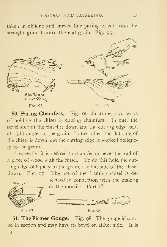
49. Oblique and Curved Line Paring.—Whethercutting with the grain or across the grain, care must be
Fig. 94.
CHISELS AND CHISELING. 57
taken in oblique and curved line paring to cut from the
straight grain toward the end grain. Fig. 95.
C. D-VVrono.OFig. 95. Fig. 96.
50. Paring Chamfers.—Fig. 96 illustrates two ways
of holding the chisel in cutting chamfers. In one, the
bevel side of the chisel is down and the cutting edge held
at right angles to the grain. In the other, the flat side of
the chisel is down and the cutting edge is worked oblique-
ly to the grain.
Frequently, it is desired to chamfer or bevel the end of
a piece of wood with the chisel. To do this hold the cut-
ting edge obliquely to the grain, the flat side of the chisel
down. Fig. 97. The use of the framing chisel is de-
scribed in connection with the making
of the mortise. Part II.sr^v
cFig. 97. Fig. 98.
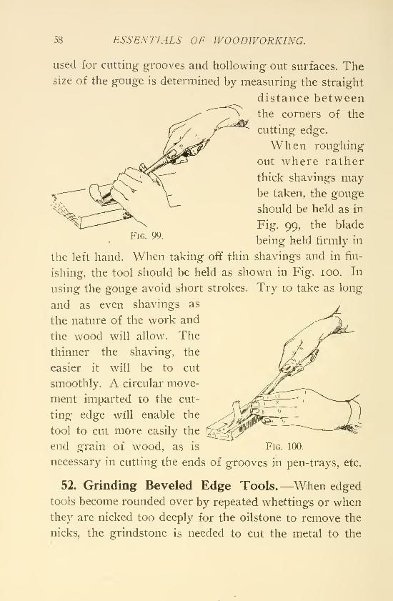
51. The Firmer Gouge.—Fig. 98. The gouge is curv-
ed in section and may have its bevel on either side. It is
58 ESSENTIALS OF WOODWORKING.
used for cutting grooves and hollowing out surfaces. Thesize of the gouge is determined by measuring the straight
distance between
the corners of the
cutting edge.
When roughing
out where rather
thick shavings maybe taken, the gouge
should be held as in
Fig. 99, the blade'
being held firmly in
the left hand. When taking off thin shavings and in fin-
ishing, the tool should be held as shown in Fig. lOO. In
using the gouge avoid short strokes. Try to take as long
and as even shavings as
the nature of the work and
the wood will allow. The
thinner the shaving, the
easier it will be to cut
smoothly. A circular move-
ment imparted to the cut-
ting edge will enable the
tool to cut more easily the
end grain of wood, as is
necessary in cutting the ends of grooves in pen-trays, etc.
52. Grinding Beveled Edge Tools.—When edged
tools become rounded over by repeated whettings or whenthey are nicked too deeply for the oilstone to remove the
nicks, the grindstone is needed to cut the metal to the
CHISELS AND CHISELING. 59
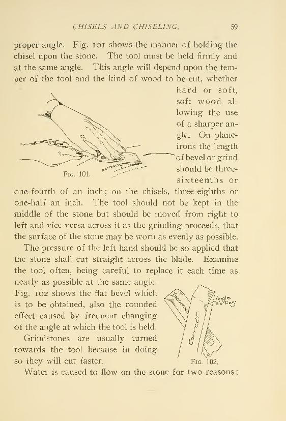
proper angle. Fig. loi shows the manner of holding the
chisel upon the stone. The tool must be held firmly and
at the same angle. This angle will depend upon the tem-
per of the tool and the kind of wood to be cut, whether
hard or soft,
soft wood al-
lowing the use
of a sharper an-
gle. On plane-
irons the length
' "~~~"of bevel or grind
should be three-
sixteenths or
one-fourth of an inch; on the chisels, three-eighths or
one-half an inch. The tool should not be kept in the
middle of the stone but should be moved from right to
left and vice versa across it as the grinding proceeds, that
the surface of the stone may be worn as evenly as ix>ssible.
The pressure of the left hand should be so applied that
the stone shall cut straight across the blade. Examine
the tool often, being careful to replace it each time as
nearly as possible at the same angle.
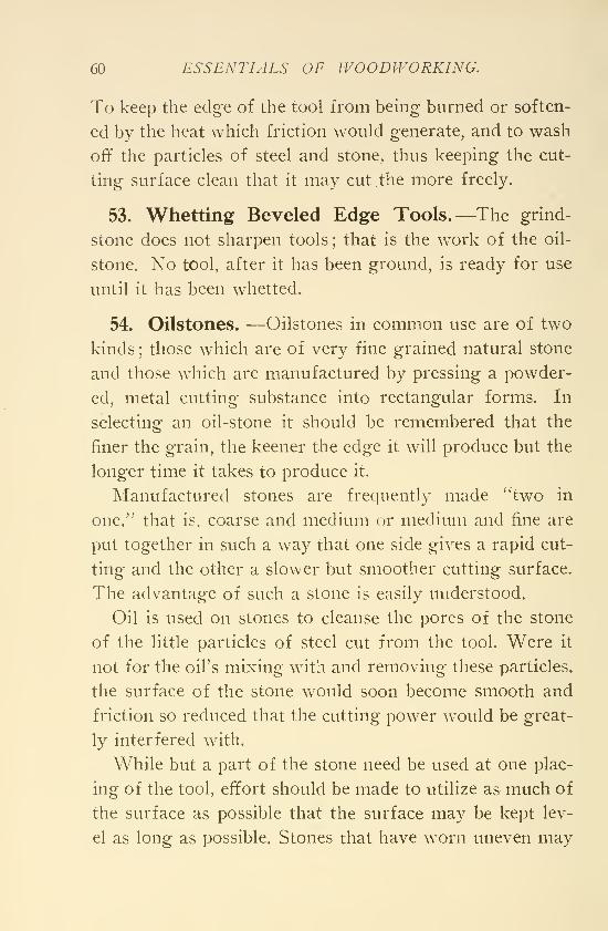
Fig. 1 02 shows the flat bevel which
is to be obtained, also the rounded
effect caused by frequent changing
of the angle at which the tool is held.
Grindstones are usually turned
towards the tool because in doing
so they will cut faster.
Water is caused to flow on the stone for two reasons
:
Fig. 102.
60 ESSENTIALS OF WOODWORKING.
To keep the edge of the tool from being burned or soften-
ed by the heat which friction would generate, and to wash
off the particles of steel and stone, thus keeping the cut-
ting surface clean that it may cut the more freely.
53. Whetting Beveled Edge Tools.—The grind-
stone does not sharpen tools; that is the work of the oil-
stone. No tool, after it has been ground, is ready for use
until it has been whetted.
54. Oilstones. —Oilstones in common use are of two
kinds ; those which are of very fine grained natural stone
and those which are manufactured by pressing a powder-
ed, metal cutting substance into rectangular forms. In
selecting an oil-stone it should be remembered that the
finer the grain, the keener the edge it will produce but the
longer time it takes to produce it.
Manufactured stones are frequently made ''two in
one," that is, coarse and medium or medium and fine are
put together in such a way that one side gives a rapid cut-
ting and the other a slower but smoother cutting surface.
The advantage of such a stone is easily understood.
Oil is used on stones to cleanse the pores of the stone
of the little particles of steel cut from the tool. Were it
not for the oil's mixing with and removing these particles,
the surface of the stone would soon become smooth and
friction so reduced that the cutting power would be great-
ly interfered with.
While but a part of the stone need be used at one plac-
ing of the tool, effort should be made to utilize as much of
the surface as possible that the surface may be kept lev-
el as long as possible. Stones that have worn uneven may
CHISELS AND CHISELING. 61
have their surfaces leveled by rubbing them on a piece of
sandpaper or emery paper placed on a flat surface.
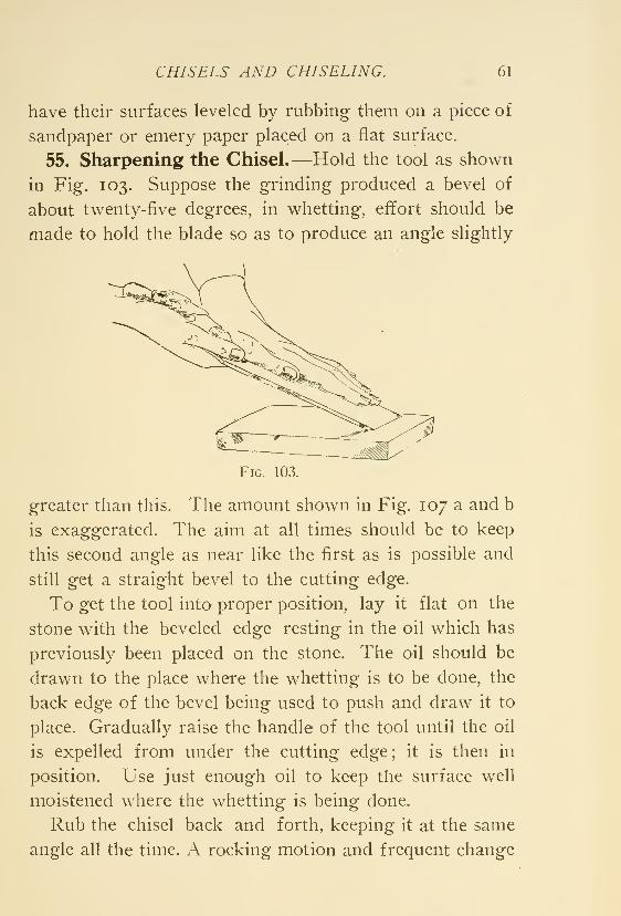
55. Sharpening the Chisel.—Hold the tool as shown
in Fig. 103. Suppose the grinding produced a bevel of
about twenty-five degrees, in whetting, effort should be
made to hold the blade so as to produce an angle slightly
Fig. 103.
greater than this. The amount shown in Fig. 107 a and b
is exaggerated. The aim at all times should be to keep
this second angle as near like the first as is possible and
still get a straight bevel to the cutting edge.
To get the tool into proper position, lay it flat on the
stone with the beveled edge resting in the oil which has
previously been placed on the stone. The oil should be
drawn to the place where the whetting is to be done, the
back edge of the bevel being used to push and draw it to
place. Gradually raise the handle of the tool until the oil
is expelled from under the cutting edge; it is then in
position. Use just enough oil to keep the surface well
moistened where the whetting is being done.
Rub the chisel back and forth, keeping it at the same
angle all the time. A rocking motion and frequent change
62 ESSENTIALS OF WOODWORKING.
of angle will result in a rounded end instead of a straight
bevel. Some workmen prefer to give the blade a circular
instead of the forward and backward movement.
To remove the feather or wire edge wdiich frequently
results from over-whetting or from grinding, proceed as
follows : Hold the tool with the flat side down, just a
little above the stone, with the handle just a very little
higher than the cutting edge. In one stroke push the cut-
ting edge forward and dow^n on the stone, at the same
time lowering the rear end to a level with the cutting
edge. The effect of this movment is to turn the wire
edge under and cut it off. If the first attempt does not
remove it, whet the bevel just enough to turn the edge
back on the flat side and try again. The presence of a
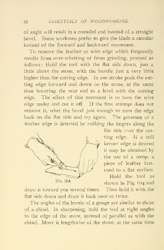
feather edge is detected by rubbing the fingers along the
flat side ever the cut-
ting edg^.. If a still
keener edge is desired
it may be obtained by
the use of a strop, a
piece of leather fast-
ened to a flat surface.
Hold the tool as
show^n in Fig. 104 and
draw it toward you several times. Then hold it with the
flat side down and draw it back once or twice.
The angles of the bevels of a gouge are similar to those
of a chisel. In sharpening, hold the tool at right angles
to the edge of the stone, instead of parallel as with the
chisel. Move it lengthwise of the stone, at the same time
Fig. 104.
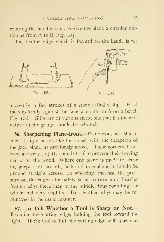
CHISELS AND CHISELING. 63
rotating the handle so as to give the blade a circular mo-
tion as from A to B, Fig. 105.
The feather edge which is formed on the inside is re-
FiG. 105 Fig. 106.
moved by a few strokes of a stone called a slip. Hold
the slip firmly against the face so as not to form a bevel.
Fig. 106. Slips are of various sizes ; one that fits the cur-
vature of the gouge should be selected.
56. Sharpening Plane-Irons.—Plane-irons are sharp-
ened straight across like the chisel, with the exception of
the jack plane, as previously noted. Their corners, how-
ever, are very slightly rounded off to prevent their leaving
marks on the wood. Where one plane is made to serve
the purpose of smooth, jack and fore-plane, it should be
ground straight across. In whetting, increase the pres-
sure on the edges alternately so as to turn up a heavier
feather edge there than in the middle, thus rounding the
whole end very slightly. This feather edge may be re-
removed in the usual manner.
57. To Tell Whether a Tool is Sharp or Not.—Examine the cutting edge, holding the tool toward the
light. If the tool is dull, the cutting edge will appear as
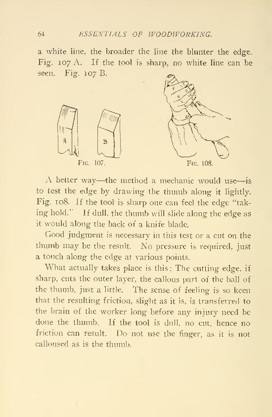
64 ESSENTIALS OF WOODWORKING.
2L white line, the broader the line the blunter the edge.
Fig. 107 A. If the tool is sharp, no white line can be
seen. Fig. 107 B.
Fig. 107. Fig. 108.
A better way—the method a mechanic would use—is
to test the edge by drawing the thumb along it lightly.
Fig. 108. If the tool is sharp one can feel the edge *'tak-
ing hold." If dull, the thumb will slide along the edge as
it would along the back of a knife blade.
Good judgment is necessary in this test or a cut on the
thumb may be the result. No pressure is required, just
a touch along the edge at various points.
What actually takes place is this : The cutting edge, if
sharp, cuts the outer layer, the callous part of the ball of
the thumb, just a little. The sense of feehng is so keen
that the resulting friction, slight as it is, is transferred to
the brain of the worker long before any injury need be
done the thumb. If the tool is dull, no cut, hence no
friction can result. Do not use the finger, as it is not
calloused as is the thumb.
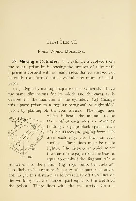
CHAPTER VL
Form Work, Modeling.
58. Making a Cylinder.—The cylinder is evolved from
the square prism by increasing the number of sides until
a prism is formed with so many sides that its surface can
be easily transformed into a cylinder by means of sand-
paper.
( I.) Begin by making a square prism which shall have
the same dimensions for its width and thickness as is
desired for the diameter of the cylinder. (2) Change
this square prism to a regular octagonal or eight-sided
prism by planing off the four arrises. The gage lines
which indicate the amount to be
taken off of each arris are made by
holding the gage block against each
of the surfaces and gaging from each
(^il' arris each way, two lines on each
surface. These lines must be made
lightly. The distance at which to set
^^J/ the spur of the gage from the head is
Fig. 109.equal to one-half the diagonal of the
square end of the prism. Fig. 109. Since the ends are
less likely to be accurate than any other part, it is advis
able to get this distance as follows : Lay off two lines on
the working face a distance apart equal to the width of
the prism. These lines with the two arrises form a
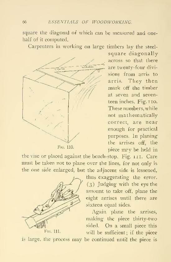
66 ESSENTIALS OF WOODWORKING.
square the diagonal of which can be measured and one-
half of it computed.
Carpenters in working on large timbers lay the steel-
square diagonally
across so that there
are twenty-four divi-
sions from arris to
arris. They then
mark off the timber
at seven and seven-
teen inches. Fig. no.
These numbers, while
not mathematically
correct, are near
enough for practical
purposes. In planing
the arrises off, the
piece mry be held in
the vise or placed against the bench-stop. Fig. in. Care
must be taken not to plane over the lines, for not only is
the one side enlarged, but the adjacent side is lessened,
thus exaggerating the error.
(3) Judging with the eye the
amount to take off, plane the
eight arrises until there are
sixteen equal sides.
Again plane the arrises,
making the piece thirty-two
sided. On a small piece this
^^^- ^^^- will be sufficient; if the piece
is large, the process may be continued until the piece is
Fig. 110.
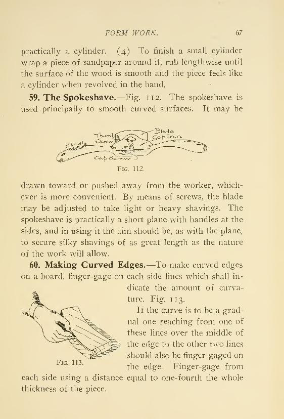
FORM WORK. 67
practically a cylinder. (4) To finish a small cylinder
wrap a piece of sandpaper around it, rub lengthwise until
the surface of the wood is smooth and the piece feels like
a cylinder when revolved in the hand.
59. The Spokeshave.—Fig. 112. The spokeshave is
used principally to smooth curved surfaces. It may be
drawn toward or pushed away from the worker, which-
ever is more convenient. By means of screws, the blade
may be adjusted to take light or heavy shavings. The
spokeshave is practically a short plane with handles at the
sides, and in using it the aim should be, as with the plane,
to secure silky shavings of as great length as the nature
of the work will allow.
60, Making Curved Edges.—To make curved edges
on a board, finger-gage on each side lines which shall in-
dicate the amount of curva-
ture. Fig. 113.
If the curve is to be a grad-
ual one reaching from one of
these lines over the middle of
the edge to the other two lines
should also be finger-gaged on
the edge. Finger-gage from
each side using a distance equal to one-fourth the whole
thickness of the piece.
Fig. 113.
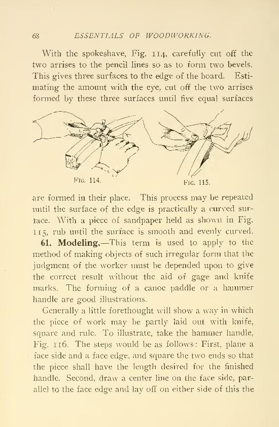
68 ESSENTIALS OF WOODWORKING.
With the spokeshave, Fig. 114, carefully cut off the
two arrises to the pencil lines so as to form two bevels.
This gives three surfaces to the edge of the board. Esti-
mating the amount with the eye, cut off the two arrises
formed by these three surfaces until five equal surfaces
Fig. 114. Fig. 115.
are formed in their place. This process may be repeated
until the surface of the edge is practically a curved sur-
tace. With a piece of sandpaper held as shown in Fig.
115, rub until the surface is smooth and evenly curved.
61. Modeling.—This term is used to apply to the
method of making objects of such irregular form that the
judgment of the worker must be depended upon to give
the correct result without the aid of gage and knife
marks. The forming of a canoe paddle or a hammer
handle are good illustrations.
Generally a little forethought will show a way in which
the piece of work may be partly laid out with knife,
square and rule. To illustrate, take the hammer handle,
Fig. 116. The steps would be as follows: First, plane a
face side and a face edge, and square the two ends so that
the piece shall have the length desired for the finished
handle. Second, draw a center line on the face side, par-
allel to the face edge and lay off on either side of this the
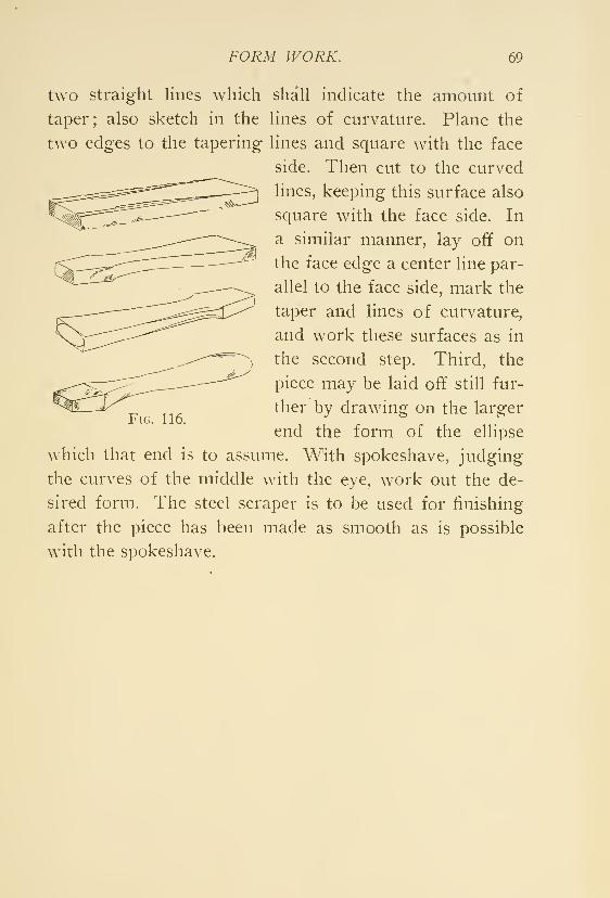
FORM WORK. 69
two straight lines which shall indicate the amount of
taper; also sketch in the lines of curvature. Plane the
two edges to the tapering lines and square wnth the face
side. Then cut to the curved
lines, keeping this surface also
square with the face side. In
a similar manner, lay off on
the face edge a center line par-
allel to the face side, mark the
taper and lines of curvature,
and work these surfaces as in
the second step. Third, the
piece may be laid off still fur-
ther by drawing on the larger
end the form of the ellipse
which that end is to assume. With spokeshave, judging
the curves of the middle with the eye, work out the de-
sired form. The steel scraper is to be used for finishing
after the piece has been made as smooth as is possible
with the spokeshave.
Fig. 116.
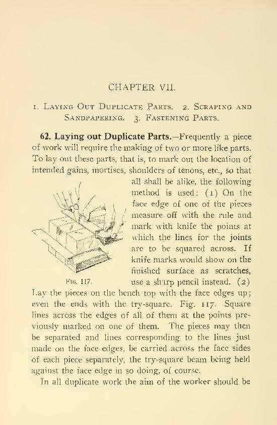
CHAPTER VII.
I. Laying Out Duplicate Parts. 2. Scraping andSandpapering. 3. Fastening Parts.
62, Laying out Duplicate Parts.—Frequently a piece
of work will require the making of two or more like parts.
To lay out these parts, that is, to mark out the location of
intended gains, mortises, shoulders of tenons, etc., so that
all shall be alike, the following
method is used: (i) On the
face edge of one of the pieces
measure off with the rule and
mark with knife the points at
which the lines for the joints
are to be squared across. If
knife marks would show on the
finished surface as scratches,
use a sh'irp pencil instead. (2)
Lay the pieces on the bench top with the face edges up;
even the ends with the try-square. Fig. 117. Square
lines across the edges of all of them at the points pre-
viously marked on one of them. The pieces may then
be separated and lines corresponding to the lines just
made on the face edges, be carried across the face sides
of each piece separately, the try-square beam being held
against the face edge in so doing, of course.
In all duplicate work the aim of the worker should be
Fig. 117.
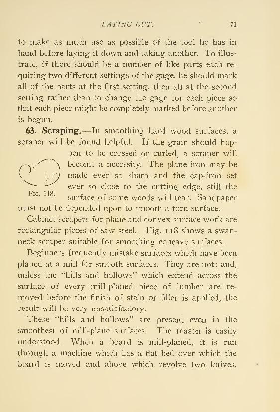
LAYING our.'
71
to make as much use as possible of the tool he has in
hand before laying it down and taking another. To illus-
trate, if there should be a number of like parts each re-
quiring two different settings of the gage, he should mark
all of the parts at the first setting, then all at the second
setting rather than to change the gage for each piece so
that each piece might be completely marked before another
is begun.
63. Scraping.—In smoothing hard wood surfaces, a
scraper will be found helpful. If the grain should hap-
pen to be crossed or curled, a scraper will
become a necessity. The plane-iron may be
made ever so sharp and the cap-iron set
ever so close to the cutting edge, still the
surface of some woods will tear. Sandpaper
must not be depended upon to smooth a torn surface.
Cabinet scrapers for plane and convex surface work are
rectangular pieces of saw steel. Fig. ii8 shows a swan-
neck scraper suitable for smoothing concave surfaces.
Beginners frequently mistake surfaces which have been
planed at a mill for smooth surfaces. They are not ; and,
unless the ''hills and hollows" which extend across the
surface of every mill-planed piece of lumber are re-
moved before the finish of stain or filler is applied, the
result will be very unsatisfactory.
These "hills and hollows" are present even in the
smoothest of mill-plane surfaces. The reason is easily
understood. When a board is mill-planed, it is run
through a machine which has a flat bed over which the
board is moved and above which revolve two knives.
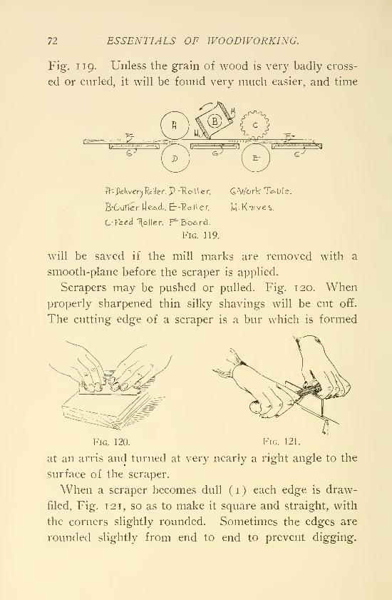
12 ESSENTIALS OF WOODWORKING.
Fig. 119. Unless the grain of wood is very badly cross-
ed or curled, it will be found very much easier, and time
fl--j)€hver^'Rcller. P -"Ro Her.
B-6vjlTer \\ e<^cL. Er -T? o 1 1 e r
C-Teeid l^oller. V^hoMi\.
Fig. 119.
-^^YT^
G-V/ork T^Ule.
W,Kr?ive^.
^
will be saved if the mill marks are removed with a
smooth-plane before the scraper is applied.
Scrapers may be pushed or pulled. Fig. 120. Whenproperly sharpened thin silky shavings will be cut off.
The cutting edge of a scraper is a bur which is formed
Fig. 120. Fig. 121.
at an arris and turned at very nearly a right angle to the
surface of the scraper.
When a scraper becomes dull ( i) each edge is draw-
filed, Fig. 121, so as to make it square and straight, with
the corners slightly rounded. Sometimes the edges are
rounded slightly from end to end to prevent digging.
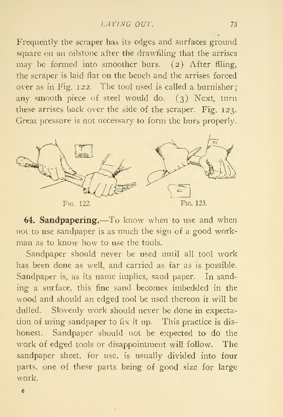
LAYING OUT. 73
Frequently the scraper has its edges and surfaces ground
square on an oilstone after the drawfihng that the arrises
may be formed into smoother burs. (2) After filing,
the scraper is laid flat on the bench and the arrises forced
over as in Fig. 122. The tool used is called a burnisher;
any smooth piece of steel would do. (3) Next, turn
these arrises back over the side of the scraper. Fig. 123.
Great pressure is not necessary to form the burs properly.
Fig. 122. Fig. 123.
64. Sandpapering,—To knov^ when to use and when
not to use sandpaper is as much the sign of a good work-
man as to know how to use the tools.
Sandpaper should never be used until all tool work
has been done as well, and carried as far as is possible.
Sandpaper is, as its name implies, sand paper. In sand-
ing a surface, this fine sand becomes imbedded in the
wood and should an edged tool be used thereon it will be
dulled. Slovenly work should never be done in expecta-
tion of using sandpaper to fix it up. This practice is dis-
honest. Sandpaper should not be expected to do the
work of edged tools or disappointment will follow. The
sandpaper sheet, for use, is usually divided into four
parts, one of these parts being of good size for large
work.
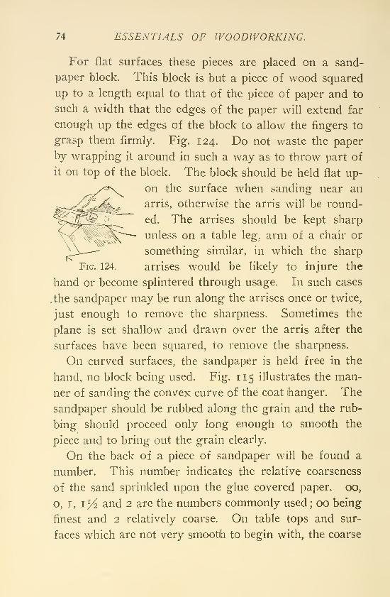
74 ESSENTIALS OF WOODWORKING.
For flat surfaces these pieces are placed on a sand-
paper block. This block is but a piece of wood squared
up to a length equal to that of the piece of paper and to
such a width that the edges of the paper will extend far
enough up the edges of the block to allow the fingers to
grasp them firmly. Fig. 124. Do not waste the paper
by wrapping it around in such a way as to throw part of
it on top of the block. The block should be held flat up-
on the surface when sanding near an
arris, otherwise the arris will be round-
ed. The arrises should be kept sharp
unless on a table leg, arm of a chair or
something similar, in which the sharp
Fig. 124. arrises would be likely to injure the
hand or become splintered through usage. In such cases
.the sandpaper may be run along the arrises once or twice,
just enough to remove the sharpness. Sometimes the
plane is set shallow and drawn over the arris after the
surfaces have been squared, to remove the sharpness.
On curved surfaces, the sandpaper is held free in the
hand, no block being used. Fig. 115 illustrates the man-
ner of sanding the convex curve of the coat hanger. The
sandpaper should be rubbed along the grain and the rub-
bing should proceed only long enough to smooth the
piece and to bring out the grain clearly.
On the back of a piece of sandpaper will be found a
number. This number indicates the relative coarseness
of the sand sprinkled upon the glue covered paper. 00,
o, I , I J^ and 2 are the numbers commonly used ; 00 being
finest and 2 relatively coarse. On table tops and sur-
faces which are not very smooth to begin with, the coarse
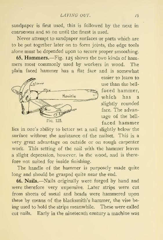
LAYING OUT. /5
sandpaper is first used, this is followed by the next in
coarseness and so on until the finest is used.
Never attempt to sandpaper surfaces or parts which are
to be put together later on to form joints, the edge tools
alone must be depended upon to secure proper smoothing.
65, Hammers.—Fig. 125 shows the two kinds of ham-
mers most commonly used by workers in wood. Theplain faced hammer has a flat face and is somewhat
easier to learn to
s'^^^ use than the bell-
'^^^m. faced hammer,Hkioale ^j which has a
slightly rounded
face. The advan-
tage of the bell-
faced hammerlies in one's ability to better set a nail slightly below the
surface without the assistance of the nailset. This is a
very great advantage on outside or on rough carpenter
work. This setting of the nail with the hammer leaves
a slight depression, however, in the wood, and is there-
fore not suited for inside finishing.
The handle of the hammer is purposely made quite
long and should be grasped quite near the end.
66. Nails.—Nails originally were forged by hand and
were therefore very expensive. Later strips were cut
from sheets of metal and heads were hammered upon
these by means of the blacksmith's hammer, the vise be-
ing used to hold the strips meanwhile. These were called
cut nails. Early in the nineteenth century a machine was
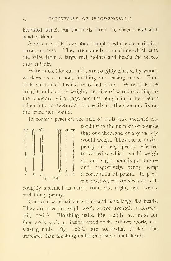
76 ESSENTIALS OF WOODWORKING.
T^ i^ "W W YT
invented which cut the nails from the sheet metal and
headed them.
Steel wire nails have about supplanted the cut nails for
most purposes. They are made by a machine which cuts
the wire from a large reel, points and heads the pieces
thus cut off.
Wire nails, like cut nails, are roughly classed by wood-
workers as common, finishing and casing nails. Thin
nails with small heads are called brads. Wire nails are
bought and sold by weight, the size of wire according to
the standard wire gage and the length in inches being
taken into consideration in specifying the size and fixing
the price per pound.
In former practice, the size of nails was specified ac-
cording to the number of pounds
that one thousand of any variety
would weigh. Thus the term six-
penny and eig"htpenny referred
to varieties which would weigh
six and eight pounds per thous-
and, respectively, penny being
B A A B c a corruption of pound. In pres-
•
ent practice, certain sizes are still
roughly specified as three, four, six, eight, ten, twenty
and thirty penny.
Common wire nails are thick and have large flat heads.
They are used in rough work where strength is desired.
Fig. 126 A. Finishing nails. Fig. 126 B, are used for
fine work such as inside woodwork, cabinet work, etc.
Casing nails, Fig. 126 C, are somewhat thicker and
stronger than finishing nails ; they have small heads.
1^ ^
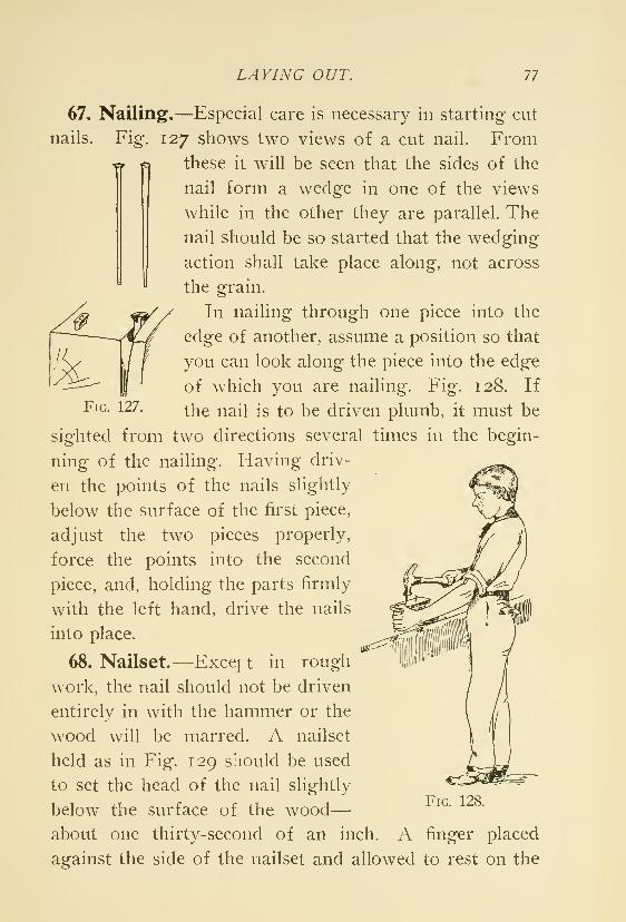
LAYING OUT. 77
Fig. 127.
67. Nailing,—Especial care is necessary in starting cut
nails. Fig. 127 shows two views of a cut nail. From
-fr f? these it will be seen that the sides of the
nail form a wedge in one of the views
while in the other they are parallel. The
nail should be so started that the wedging
action shall take place along, not across
the grain.
In nailing through one piece into the
edge of another, assume a position so that
you can look along the piece into the edge
of which you are nailing. Fig. 128. If
the nail is to be driven plumb, it must be
sighted from two directions several times in the begin-
ning of the nailing. Having driv-
en the points of the nails slightly
below the surface of the first piece,
adjust the two pieces properly,
force the points into the second
piece, and, holding the parts firmly
with the left hand, drive the nails
into place.
68. Nailset.—Excej t in rough
work, the nail should not be driven
entirely in with the hammer or the
wood will be marred. A nailset
held as in Fig. 129 should be used
to set the head of the nail slightly
below the surface of the wood
—
about one thirty-second of an inch. A finger placed
against the side of the nailset and allowed to rest on the
Fig. 128.
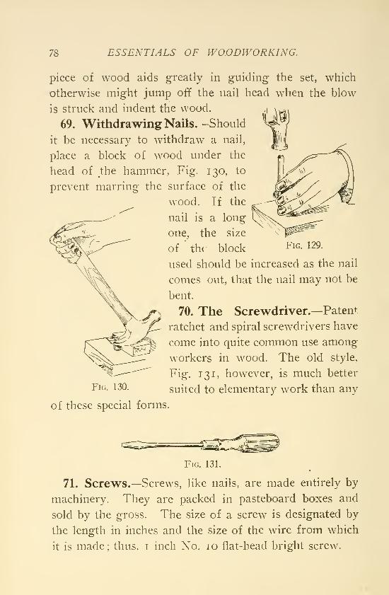
78 ESSENTIALS OF WOODWORKING.
piece of wood aids greatly in guiding the set, which
otherwise might jump off the nail head when the blow
is struck and indent the wood.
69. Withdrawing Nails. -Should
it be necessary to withdraw a nail,
place a block of wood under the
head of ^the hammer. Fig. 130, to
prevent marring the surface of the
wood. If the
nail is a long
one, the size
of'
th( block Fig. 129.
used should be increased as the nail
comes out, that the nail may not be
bent.
70. The Screwdriver.—Patent
ratchet and spiral screwdrivers have
come into quite common use among
workers in wood. The old style.
Fig. 131, however, is much better
Fig. 130. suited to elementar}^ work than any
of these special forms.
Fig. 131.
71. Screws.—Screws, like nails, are made entirely by
machinery. They are packed in pasteboard boxes and
sold by the gross. The size of a screw is designated by
the length in inches and the size of the wire from which
it is made; thus, i inch No. 10 flat-head bright screw.
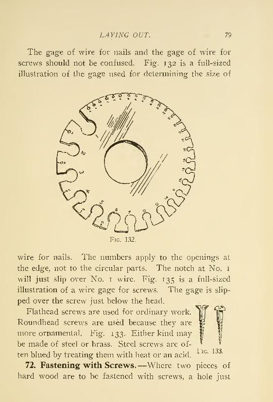
LAYING OUT. 79
The gage of wire for nails and the gage of wire for
screws should not be confused. Fig. 132 is a full-sized
illustration of the gage used for determining the size of
7^
Fig. 132.
wire for nails. The numbers apply to the openings at
the edge, not to the circular parts. The notch at No. i
will just slip over No. i wire. Fig. 135 is a full-sized
illustration of a wire gage for screws. The gage is slip-
ped over the screw just below the head.
Flathead screws are used for ordinary work.
Roundhead screws are used because they are
more ornamental. Fig. 133. Either kind maybe made of steel or brass. Steel screws are of-
ten blued by treating them with heat or an acid.
72. Fastening with Screws.—Where two pieces of
hard wood are to be fastened with screws, a hole just
I'iG. 133.
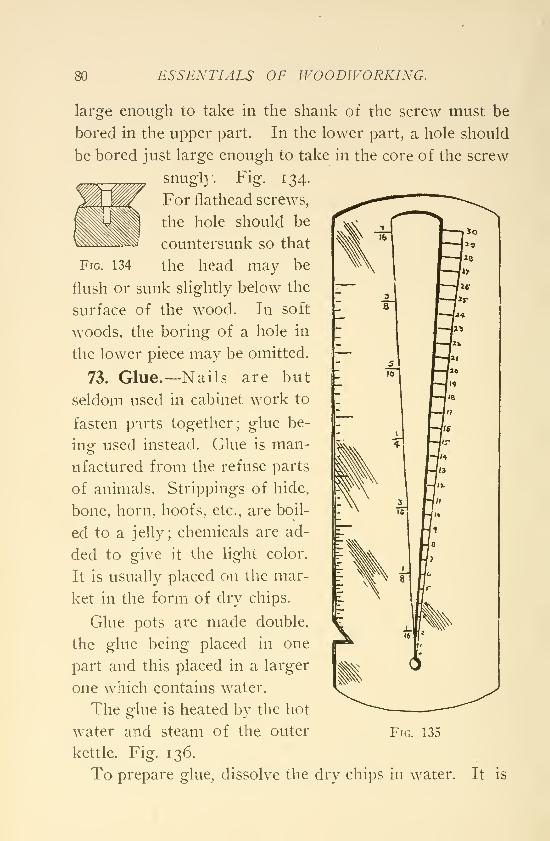
80 ESSENTIALS OF WOODWORKING.
large enough to take in the shank of the screw must be
bored in the upper part. In the loAver part, a hole should
be bored just large enough to take in the core of the screw
snugl]. Fig. 134.
For flathead screws,
the hole should be
countersunk so that
Fig. 134 the head may be
flush or sunk slightly below the
surface of the wood. In soft
woods, the boring of a hole in
the lower piece may be omitted.
73. Glue.—Nails are but
seldom used in cabinet work to
fasten pirts together; glue be-
ing used instead. Glue is man-
ufactured from the refuse parts
of animals. Strippings of hide,
bone, horn, hoofs, etc., are boil-
ed to a jelly; chemicals are ad-
ded to give it the light color.
It is usually placed on the mar-
ket in the form of dry chips.
Glue pots are made double,
the glue being placed in one
part and this placed in a larger
one which contains water.
The glue is heated by the hot
water and steam of the outer
kettle. Fig. 136.
To prepare glue, dissolve the dry chips in water
Fig. 135
It is
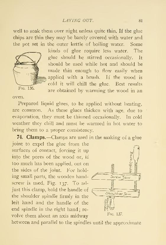
LAYING OUT. 81
well to soak them over night unless quite thin. If the glue
chips are thin they may be barely covered with water and
the pot set in the outer kettle of boiling water. Somekinds of glue require less water. The
glue should be stirred occasionally. It
should be used while hot and should be
made thin enough to flow easily when
applied with a brush. If the wood is
cold it will chill the elue. Best results
are obtained by warming the wood in an
oven.
Prepared liquid glues, to be applied without heating,
are common. As these glues thicken with age, due to
evaporation, they must be thinned occasionally. In cold
weather they chill and must be warmed in hot water to
bring them to a proper consistency.
74. Clamps.—Clamps are used in the making of a glue
joint to expel the glue from the
surfaces of contact, forcing it up
into the pores of the wood or, if
too' much has been applied, out on
the sides of the joint. For hold-
ing small parts, the wooden hand-
screw is used, Fig. 137. To ad-
just this clamp, hold the handle of n- ~-^
the shoulder spindle firmly in the =~7^r^=^^left hand and the handle of the t:f|
end spindle in the right hand; re- K^^^
volve them about an axis midwaybetween and parallel to the spindles until the approximate
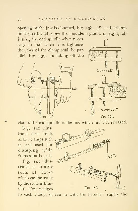
82 ESSENTIALS OF WOODWORKING.
Opening of the jaw is obtained, Fig. 138. Place the clamp
on the parts and screw the shoulder spindle up tight, ad-
justing the end spindle when neces-
sary so that when it is tightened
the jaws of the clamp shall be par-
allel. Fig. 139. In taking off this
m[QcorrecT^
Fig. 138. Fig. 139.
clamp, the end spindle is the one which must be released.
Fig. 140 illus-
trates three kinds
of bar clamps such
as are used for
clamping wide
frames and boards.
Fig. 141 illus-
trates a simple
form of clamp
which can be made
by the student him-
self. Two wedges Fig. UO.
to each clamp, driven in with the hammer, supply the
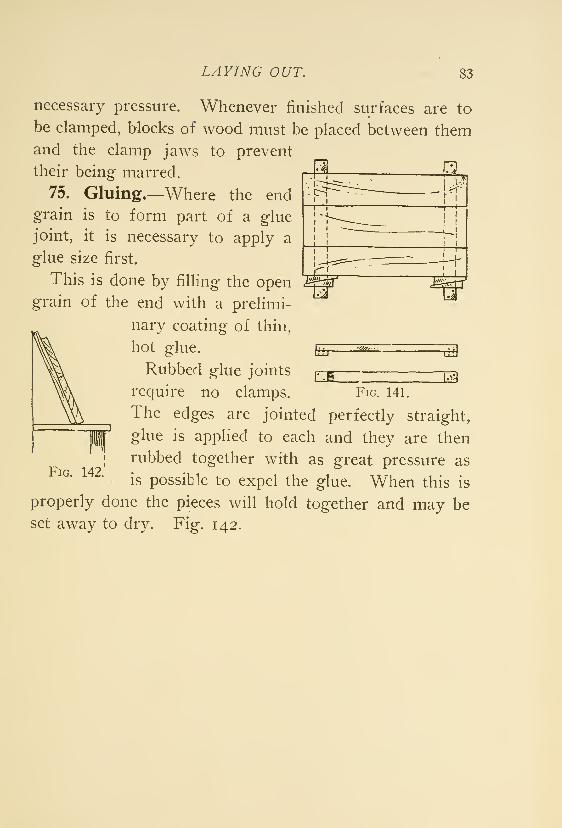
LAYING OUT. 83
necessary pressure. Whenever finished surfaces are to
be clamped, blocks of wood must be placed between themand the clamp jaws to prevent
their being marred.
75. Gluing.—Where the end
grain is to form part of a glue
joint, it is necessary to apply a
glue size first.
This is done by filling the open'
-^4^
grain of the end with a prelimi-
nary coating of thin,
hot glue. ^Rubbed glue joints
require no clamps.
U-
::£. sFig. 141.
The edges are jointed perfectly straight,
glue is applied to each and they are then
rubbed together with as great pressure as
is possible to expel the glue. When this is
properly done the pieces will hold together and may be
set away to dry. Fig. 142.
Fig. 142.'
PART 11.
SIMPLE JOINERY.
Chapter VIII.
Type Forms.
76. Joinery.—This term in its broader meaning refers
to the art of framing the finishing work of a house, such
as doors and windows; and to the construction of per-
manent fittings, such as mantels, cupboards, hnen presses,
etc. Joinery as used herein refers merely to the putting
together of two or more parts, called the members.
77. General Directions for Joinery:—Take into con-
sideration the direction of the grain in planning the rela-
tive positions of the members. Make due allowance where
shrinkage is likely to be considerable.
As far as possible, plan to have the members join face
to face. Face sides are more likely to be true than are
the other two surfaces and therefore the joints are more
likely to fit properly.
Make all measurements from a common starting point,
as far as practicable. Remember to keep the head of the
gage, and the beam of the trysquare against one or the
other of the faces, unless there should be special reasons
for doing otherwise.
In practice it is sometimes advisable to locate the sides
of a joint by superposition rather than by measurement.
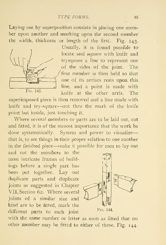
TYPE FORMS. 85
Fig. 143.
Laying out by superposition consists in placing one mem-ber upon another and marking upon the second memberthe width, thickness or length of the first. Fig. 143.
Usually, it is found possible to
locate and square with knife and
trysquare a line to represent one
of the sides of the joint. The/first member is then held so that
one of its arrises rests upon this
line, and a point is made with
knife at; the other arris. Thesuperimposed piece is then removed and a line made with
knife and try-square—not thru the mark of the knife
point but inside, just touching it.
Where several members or parts are to be laid out, cut
and fitted, it is of the utmost importance that the work be
done systematically. System and power to visualize
—
that is, to see things in their proper relation to one another
in the finished piece—make it possible for men to lay out
and cut the members to the
most intricate frames of build-
ings before a single part has
been put together. Lay out
duplicate parts and duplicate
joints as suggested in Chapter
VII, Section 62. Where several
joints of a similar size and
kind are to be fitted, mark the
different parts to each joint
with the same number or letter as soon as fitted that no
other member may be fitted to either of these. Fig. 144.
Fig. 144.
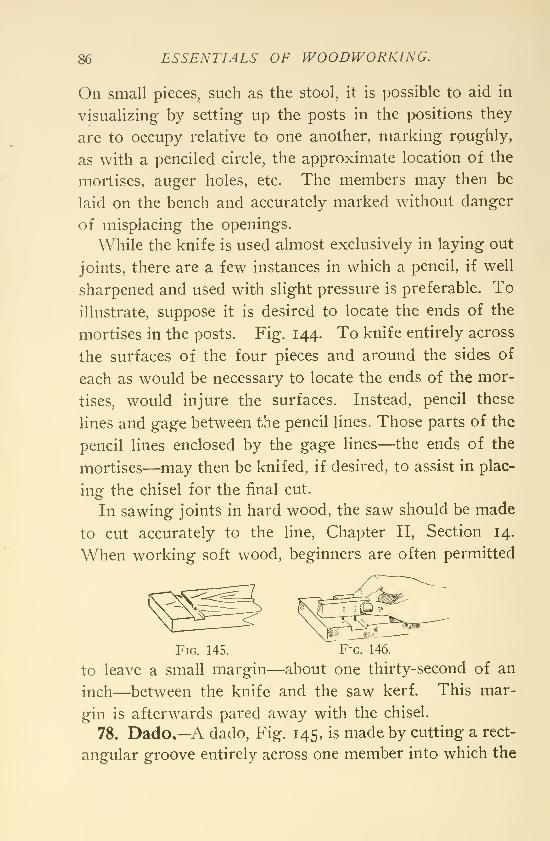
86 ESSENTIALS OF WOODWORKING.
On small pieces, such as the stool, it is possible to aid in
visualizing by setting up the posts in the positions they
are to occupy relative to one another, marking roughly,
as with a penciled circle, the approximate location of the
mortises, auger holes, etc. The members may then be
laid on the bench and accurately marked without danger
of misplacing the openings.
While the knife is used almost exclusively in laying out
joints, there are a few instances in which a pencil, if well
sharpened and used with slight pressure is preferable. To
illustrate, suppose it is desired to locate the ends of the
mortises in the posts. Fig. 144. To knife entirely across
the surfaces of the four pieces and around the sides of
each as would be necessary to locate the ends of the mor-
tises, would injure the surfaces. Instead, pencil these
lines and gage between the pencil lines. Those parts of the
pencil lines enclosed by the gage lines—the ends of the
mortises^—may then be knifed, if desired, to assist in plac-
ing the chisel for the final cut.
In sawing joints in hard wood, the saw should be made
to cut accurately to the line, Chapter II, Section 14.
When working soft wood, beginners are often permitted
Fig. 145. F'g. 146.
to leave a small margin—about one thirty-second of an
inch—^between the knife and the saw kerf. This mar-
gin is afterwards pared away with the chisel.
78. Dado,—A dado. Fig. 145, is made by cutting a rect-
angular groove entirely across one member into which the
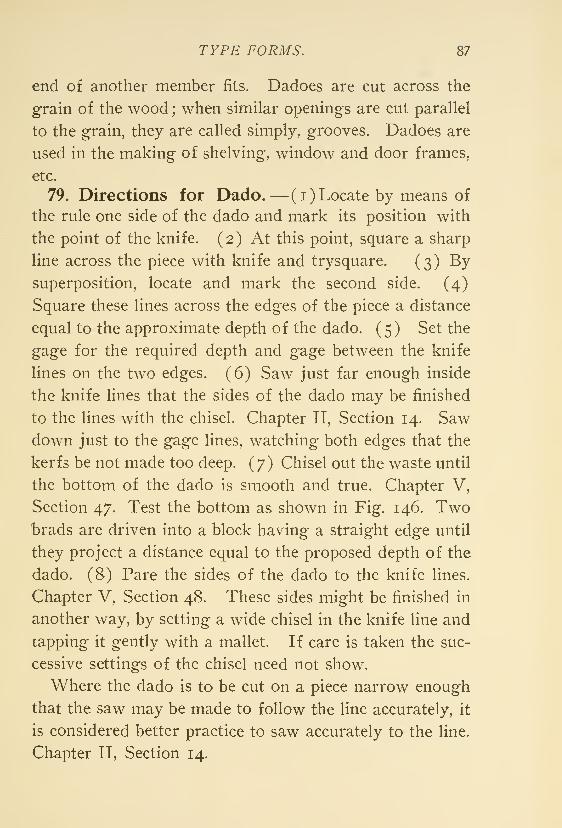
TYPE FORMS. 87
end of another member fits. Dadoes are cut across the
grain of the wood ; when similar openings are cut parallel
to the grain, they are called simply, grooves. Dadoes are
used in the making of shelving, window and door frames,
etc.
79. Directions for Dado.— ( i ) Locate by means of
the rule one side of the dado and mark its position with
the point of the knife. (2) At this point, square a sharp
line across the piece with knife and trysquare. (3) Bysuperposition, locate and mark the second side. (4)
Square these lines across the edges of the piece a distance
equal to the approximate depth of the dado. (5) Set the
gage for the required depth and gage between the knife
lines on the two edges. (6) Saw just far enough inside
the knife lines that the sides of the dado may be finished
to the lines with the chisel. Chapter II, Section 14. Sawdown just to the gage lines, watching both edges that the
kerfs be not made too deep. (7) Chisel out the waste until
the bottom of the dado is smooth and true. Chapter V,
Section 47. Test the bottom as shown in Fig. 146. Twobrads are driven into a block having a straight edge until
they project a distance equal to the proposed depth of the
dado. (8) Pare the sides of the dado to the knife lines.
Chapter V, Section 48. These sides might be finished in
another way, by setting a wide chisel in the knife line and
tapping it gently with a mallet. If care is taken the suc-
cessive settings of the chisel need not show.
Where the dado is to be cut on a piece narrow enough
that the saw may be made to follow the line accurately, it
is considered better practice to saw accurately to the line.
Chapter II, Section 14.
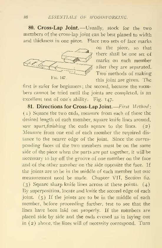
88 ESSENTIALS OF WOODWORKING.
80. Cross-Lap Joint.—Usually, stock for the twomembers of the cross-lap joint can be best planed to width
and thickness in one piece. Place two sets of face marks
on the piece, so that
there shall be one set of
marks on each memberafter they are separated.
Two methods of makingFig. 147. +u- • • .
• t-ithis jomt are given, i he
first is safer for beginners ; the second, because the mem-bers cannot be tried until the joints are completed, is an
excellent test of one's ability. Fig. 147.
81. Directions for Cross-Lap Joint.—First Method:
( I ) Square the two ends, measure from each of these the
desired length of each member, square knife lines around,
saw apart,finishing the ends square to the lines. (2)
Measure from one end of each member the required dis-
tance to the nearer edge of the joint. Since the corres-
ponding faces of the two members must be on the same
side of the piece when the parts are put together, it will be
necessary to lay off the groove of one member on the face
and of the other member on the side opposite the face. If
the joints are to be in the middle of each member but one
measurement need be made. Chapter VII, Section 62.
(3) Square sharp knife lines across at these points. (4)
By superposition, locate and knife the second edge of each
joint. (5) If the joints are to be in the middle of each
member, before proceeding further, test to see that the
lines have been laid out properly. If the members are
placed side by side and the ends evened as in laying out
in (2) above, the lines will of necessity correspond. Turn
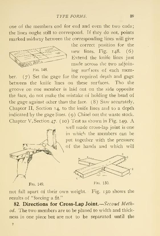
TYPE FORMS. 89
one of the members end for end and even the two ends;
the Hnes ought still to correspond. If they do not, points
marked midway between the corresponding lines will give
the correct position for the
new lines, Fig. 148. (6)
Extend the knife lines just
made across the two adjoin-
FiG. 148. ing surfaces of each mem-
ber. (7) Set the g*age for the required depth and gage
between the knife lines on these surfaces. Tho the
groove on one member is laid out on the side opposite
the face, do not make the mistake of holding the head of
the gage against other than the face. (8) Saw accurately,
Chapter II, Section 14, tO' the knife lines and tO' a depth
indicated by the gage lines. (9) Chisel out the waste stock.
Chapter V, Section 47. (10) Test as shown in Fig. 149. Awell made cross-lap joint is one
in which the members can be
put together with the pressure
of the hands and which will
Fig. 149. Fig. 150.
not fall apart of their own weight. Fig. 150 shows the
results of "forcing a fit."
82. Directions for Cross-Lap ioint.—Second Meth-
od. The two members are to be planed to width and thick-
ness in one piece but are not to be separated until the
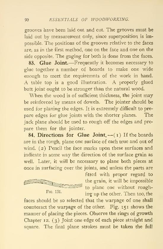
90 ESSENTIALS OF WOODWORKING.
grooves have been laid out and cut. The grooves must be
laid out by measurement only, since superposition is im-
possible. The positions of the grooves relative to the faces
are, as in the first method, one on the face and one on the
side opposite. The gaging for both is done from the faces.
83. Glue Joint.—Frequently it becomes necessary to
glue together a number of boards to make one wide
enough to meet the requiremnts of the work in hand.
A table top is a good illustration. A properly glued
butt joint ought to be stronger than the natural wood.
When the wood is of sufficient thickness, the joint may
be reinforced by means of dowels. The jointer should be
used for planing the edges. It is extremely difficult to pre-
pare edges for glue joints with the shorter planes. The
jack plane should be used to rough off the edges and pre-
pare them for the jointer.
84, Directions for Glue Joint.—(i) If the boards
are in the rough, plane one surface of each true and out of
wind. (2) Pencil the face marks upon these surfaces and
indicate in some way the direction of the surface grain as
well. Later, it will be necessary to plane both pieces at
once in surfacing over the joints, and unless the parts are
fitted with proper regard to
the grain, it will be impossible
to plane one without rough-FiG 1 SI
in^ Up the Other. Then too, the
faces should be so selected that the warpage of one shall
counteract the warpage of the other. Fig. 151 shows the
manner of placing the pieces. Observe the rings of growth
Chapter 12. (3) Joint one edge of each piece straight and
square. The final plane strokes must be taken the full
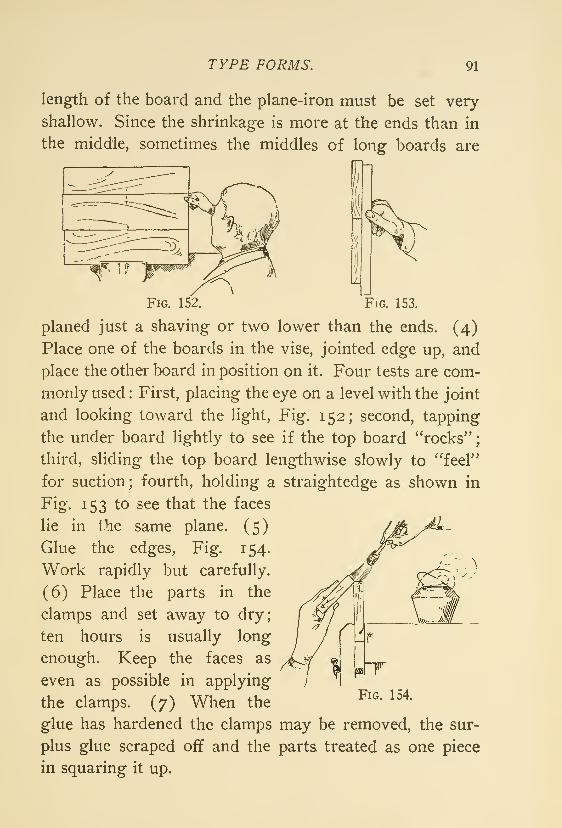
TYPE FORMS. 91
length of the board and the plane-iron must be set very
shallow. Since the shrinkage is more at the ends than in
the middle, sometimes the middles of long boards are
Fig. 152. Fig. 153.
planed just a shaving or two lower than the ends. (4)
Place one of the boards in the vise, jointed edge up, and
place the other board in position on it. Four tests are com-
monly used : First, placing the eye on a level with the joint
and looking toward the light, Fig. 152; second, tapping
the under board lightly to see if the top board "rocks"
;
third, sliding the top board lengthwise slowly to "feel"
for suction; fourth, holding a straightedge as shown in
Fig. 153 to see that the faces
lie in the same plane. (5)
Glue the edges, Fig. 154.
Work rapidly but carefully.
(6) Place the parts in the
clamps and set away to dry;
ten hours is usually long
enough. Keep the faces as ,
even as possible in applying
the clamps. (7) When the
glue has hardened the clamps may be removed, the sur-
plus glue scraped off and the parts treated as one piece
in squaring it up.
S^i-'^
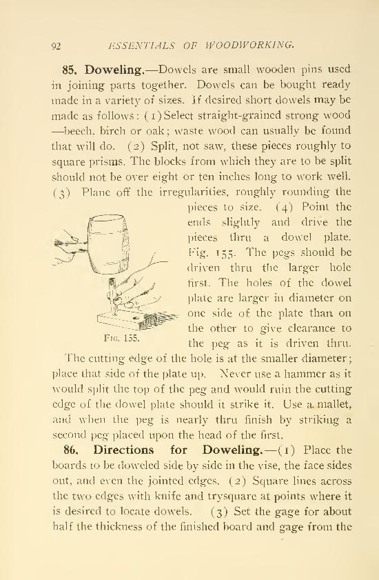
92 ESSENTIALS OF WOODWORKING,
85, Doweling,—Dowels are small wooden pins used
in joining parts together. Dowels can be bought ready
made in a variety of sizes. If desired short dowels may be
made as follows : ( i ) Select straight-grained strong wood
—beech, birch or oak; waste wood can usually be found
that will do. (2) Split, not saw, these pieces roughly to
square prisms. The blocks from which they are to be split
should not be over eight or ten inches long to work well.
(3) Plane off the irregularities, roughly rounding the
pieces to size. (4) Point the
ends slightly and drive the
pieces thru a dowel plate.
Fig. 155. The pegs should be
driven thru the larger hole
first. The holes of the dowel
plate are larger in diameter on
one side of the plate than on
the other to give clearance to
the peg as it is driven thru.
The cutting edge of the hole is at the smaller diameter
;
place that side of the plate up. Never use a hammer as it
would split the top of the peg and would ruin the cutting
edge of the dowel plate should it strike it. Use a. mallet,
and when the peg is nearly thru finish by striking a
second peg placed upon the head of the first.
86, Directions for Doweling.— (i) Place the
boards to be doweled side by side in the vise, the face sides
out, and even the jointed edges. (2) Square lines across
the two edges with knife and trysquare at points where it
is desired to locate dowels. (3) Set the gage for about
half the thickness of the finished board and gage from the
Fig. 155.
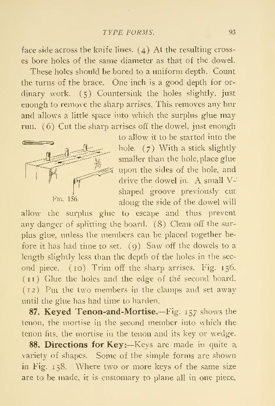
TYPE FORMS. 93
face side across the knife lines. (4) At the resulting cross-
es bore holes of the same diameter as that of the dowel.
These holes should be bored to a uniform depth. Count
the turns of the brace. One inch is a good depth for or-
dinary work. (5) Countersink the holes slightly, just
enough to remove the sharp arrises. This removes any bur
and allows a little space into which the surplus glue may
run. (6) Cut the sharp arrises off the dowel, just enough
to allow it to be started into the
hole. (7) With a stick slightly
smaller than the hole, place glue
upon the sides of the hole, and
drive the dowel in. A small V-'
shaped groove previously cut
^^^- ^^^-along the side of the dowel will
allow the surplus glue to escape and thus prevent
any danger of splitting the board. (8) Clean off the sur-
plus glue, unless the members can be placed together be-
fore it has had time to set. (9) Saw off the dowels to a
length slightly less than the depth of the holes in the sec-
ond piece. (10) Trim off the sharp arrises. Fig. 156.
(11) Glue the holes and the edge of the second board.
(12) Put the two members in the clamps and set away
until the glue has had time to harden.
87, Keyed Tenon-and-Mortise,—Fig. 157 shows the
tenon, the mortise in the second member into which the
tenon fits, the mortise in the tenon and its key or wedge.
88. Directions for Key:—Keys are made in quite a
variety of shapes. Some of the simple forms are shown
in Fig. 158. Where two or more keys of the same size
are to be made, it is customary to plane all in one piece.
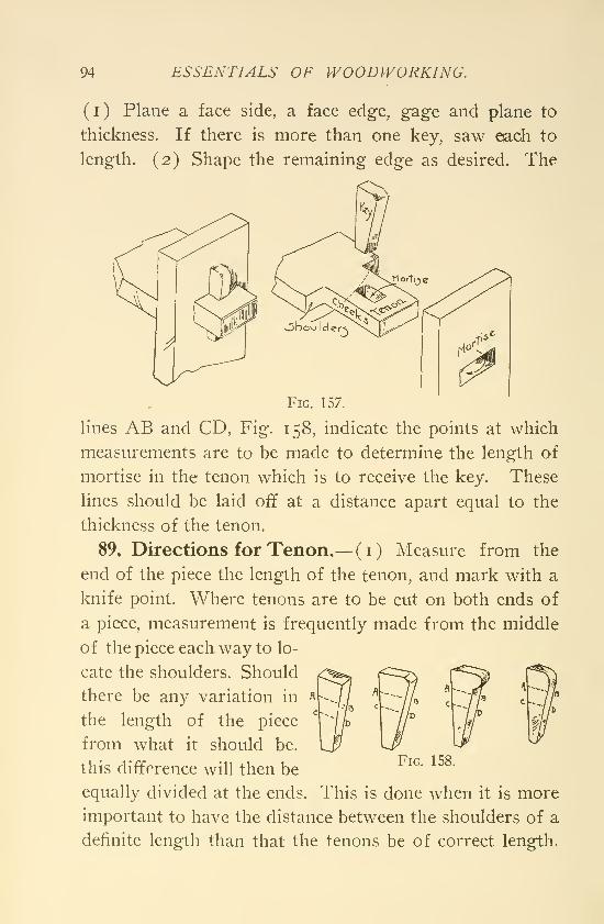
94 ESSENTIALS OF WOODWORKING.
(i) Plane a face side, a face edge, gage and plane to
thickness. If there is more than one key, saw each to
length. (2) Shape the remaining edge as desired. The
Fig. 157.
lines AB and CD, Fig. 158, indicate the points at which
measurements are to be made to determine the length of
mortise in the tenon which is to receive the key. These
lines should be laid off at a distance apart equal to the
thickness of the tenon.
89, Directions for Tenon,— (i) Measure from the
end of the piece the length of the tenon, and mark with a
knife point. Where tenons are to be cut on both ends of
a piece, measurement is frequently made from the middle
of the piece each way to lo-
cate the shoulders. Should
there be any variation in
the length of the piece
from what it should be.
this difference will then be
equally divided at the ends. This is done when it is more
important to have the distance between the shoulders of a
definite length than that the tenons be of correct length.
Fig. 158.
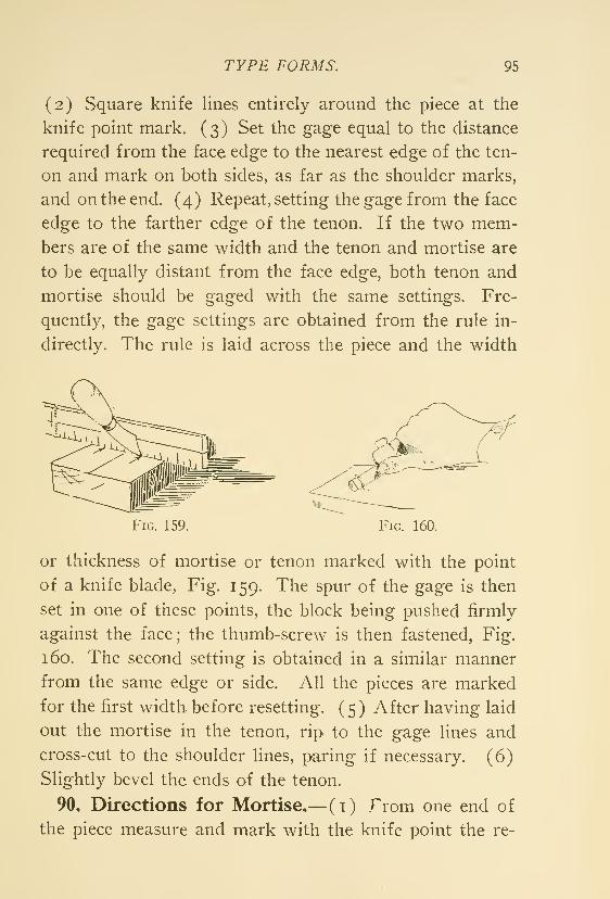
TYPE FORMS. 95
(2) Square knife lines entirely around the piece at the
knife point mark. (3) Set the gage equal to the distance
required from the face edge to the nearest edge of the ten-
on and mark on both sides, as far as the shoulder marks,
and on the end. (4) Repeat, setting the gage from the face
edge to the farther edge of the tenon. If the two mem-bers are of the same width and the tenon and mortise are
to be equally distant from the face edge, both tenon and
mortise should be gaged with the same settings. Fre-
quently, the gage settings are obtained from the rule in-
directly. The rule is laid across the piece and the width
Fig. 159. Fig. 160.
or thickness of mortise or tenon marked with the point
of a knife blade. Fig. 159. The spur of the gage is then
set in one of these points, the block being pushed firmly
against the face; the thumb-screw is then fastened, Fig.
160. The second setting is obtained in a similar manner
from the same edge or side. All the pieces are marked
for the first width before resetting. (5) After having laid
out the mortise in the tenon, rip to the gage lines and
cross-cut to the shoulder lines, paring if necessary. (6)
Slightly bevel the ends of the tenon.
90, Directions for Mortise,— (i) From one end of
the piece measure and mark with the knife point the re-
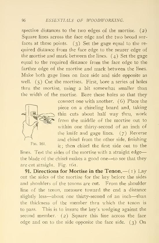
96 ESSENTIALS OF WOODWORKING.
spective distances to the two edges of the mortise. (2)
Square lines across the face edge and the two broad sur-
faces at these points. (3) Set the gage equal to the re-
quired distance from the face edge to the nearer edge of
the mortise and mark between the lines. (4) Set the gage
equal to the required distance from the face edge to the
farther edge of the mortise and mark between the lines.
Make both gage lines on face side and side opposite as
well. (5) Cut the mortises. First, bore a series of holes
thru the mortise, using a bit somewhat smaller than
the width of the mortise. Bore these holes so that they
connect one with another. (6) Place the
piece on a chiseling board and, taking
thin cuts about half way thru, work
^^^ from the middle of the mortise out to
within one thirty-second of an inch of
the knife and gage lines. (7) Reverse
and chisel from the other side, finishingFig. 161. -^
. ^^^^^ chisel the first side out to the
lines. Test the sides of the mortise with a straight edge
—
the blade of the chisel makes a good one—to see that they
are cut straight. Fig. 161.
91, Directions for Mortise in the Tenon.— (i ) Lay
out the sides of the mortise for the key before the sides
and shoulders of the tenons are cut. From the shoulder
line of the tenon, measure toward the end a distance
slightly less—about one thirty-second of an inch—than
the thickness of the member thru which the tenon is
to pass. This is to insure the key's wedging against the
second member. (2) Square this line across the face
edge and on to the side opposite the face side. (3) On
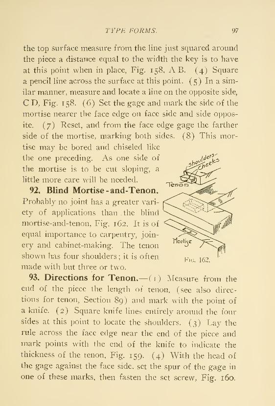
TYPE FORMS. 97
^M.^i^-^t'*
the top surface measure from the line just squared around
the piece a distance equal to the width the key is to have
at this point when in place, Fig. 158, A B. (4) Square
a pencil line across the surface at this point. (5) In a sim-
ilar manner, measure and locate a line on the opposite side,
C D, Fig. 158. (6) Set the gage and mark the side of the
mortise nearer the face edge on face side and side oppos-
ite. (7) Reset, and from the face edge gage the farther
side of the mortise, marking both sides. (8) This mor-
tise may be bored and chiseled like
the one preceding. As one side of
the mortise is to be cut sloping, a
little more care will be needed.
92, Blind Mortise -and-Tenon,
Probably no joint has a greater vari-
ety of applications than .the blind
mortise-and-tenon. Fig. 162. It is of
equal importance to carpentry, join-
ery and cabinet-making. The tenon
shown has four shoulders ; it is often
made with but three or two.
93, Directions for Tenon,— (i) Measure from the
end of the piece the length of tenon, (see also direc-
tions for tenon. Section 89) and mark with the point of
a knife. (2) Square knife lines entirely around the four
sides at this point to locate the shoulders. (3) Lay the
rule across the face edge near the end of the piece andmark points with the end of the knife to indicate the
thickness of the tenon, Fig. 159. (4) With the head of
the gage against the face side, set the spur of the gage in
one of these marks, then fasten the set screw, Fig. 160.
Fig. 162.
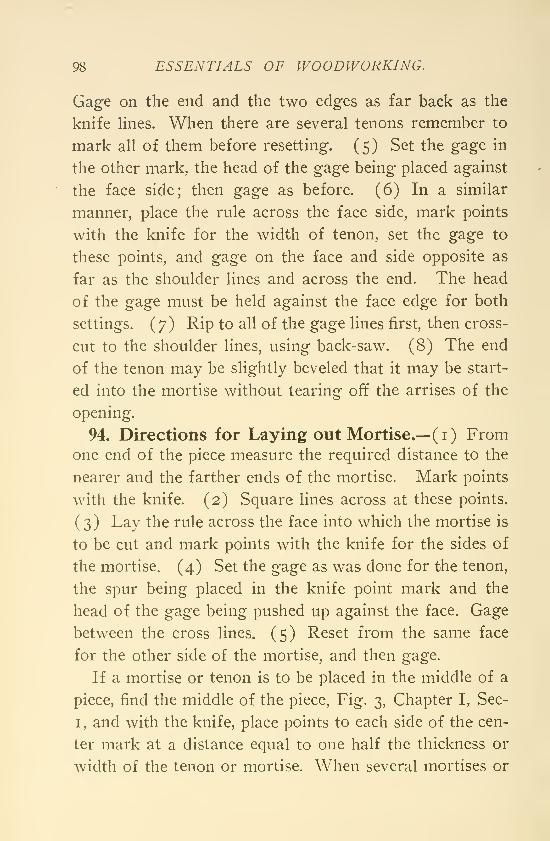
98 ESSENTIALS OF WOODWORKING.
Gage on the end and the two edges as far back as the
knife lines. When there are several tenons remember to
mark all of them before resetting. (5) Set the gage in
the other mark, the head of the gage being placed against
the face side; then gage as before. (6) In a similar
manner, place the rule across the face side, mark points
with the knife for the width of tenon, set the gage to
these points, and gage on the face and side opposite as
far as the shoulder lines and across the end. The head
of the gage must be held against the face edge for both
settings. (7) Rip to all of the gage lines first, then cross-
cut to the shoulder lines, using back-saw. (8) The end
of the tenon may be slightly beveled that it may be start-
ed into the mortise without tearing off the arrises of the
opening.
94. Directions for Laying out Mortise,— (i) Fromone end of the piece measure the required distance to the
nearer and the farther ends of the mortise. Mark points
with the knife. (2) Square lines across at these points.
( 3 ) Lay the rule across the face into which the mortise is
to be cut and mark points with the knife for the sides of
the mortise. (4) Set the gage as was done for the tenon,
the spur being placed in the knife point mark and the
head of the gage being pushed up against the face. Gage
between the cross lines. (5) Reset from the same face
for the other side of the mortise, and then gage.
If a mortise or tenon is to be placed in the middle of a
piece, find the middle of the piece, Fig. 3, Chapter I, Sec-
I, and with the knife, place points to each side of the cen-
ter mark at a distance equal to one half the thickness or
width of the tenon or mortise. When several mortises or
TYPE FORMS. 99
tenons of the same size are to be laid out and are to be
equally distant from a face, the gage needs to be set but
twice for all—once to mark the nearer edges and once for
the farther edges of the tenon or mortise. Should there be
several like members with like joints, the gage settings
obtained from the first piece will suffice for all.
The importance of working from face sides or face
edges only, cannot be overestimated. To work from eith-
er of the other two sides of a piece would make the joints
subject to any variation in the widths or thicknesses of
the pieces. To gage from the faces only, insures mortises
and tenons of exact size no matter how much the pieces
may vary in widths or thicknesses.
95, Directions for Cutting Mortise, —Two methods
of cutting mortises are in common use, (a) boring and
chiseling, and (b) chiseling alone. First method: (i)
Fasten the piece in the vise in a horizontal position. (2)
Bore a series of connecting holes to the required depth.
Chapter IV, Section 45, with a bit slightly smaller than the
width of the mortise. (3) The sides of the mortise are
next pared to the gage and knife lines, beginning at the
auger holes and working with thin slices toward the lines.
This method requires care and patience in order to get the
sides of the mortise cut square to the surface. It is es-
pecially well adapted to large mortises from which much
wood is to be removed.
96. Directions for Cutting Mortise,—Second Meth-
od: ( I ) Clamp the piece which is to be mortised firmly
to the bench top, using a hand clamp. Fig. 163 shows a
little device called a mortise grip. Tighten the vise screw
and tap the grip with the mallet until it holds the piece
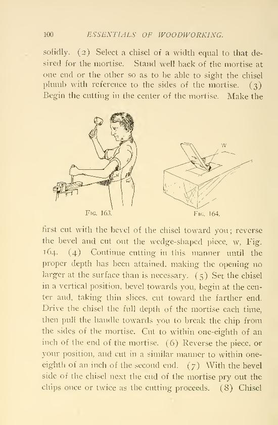
100 ESSENTIALS OF WOODWORKING.
solidly. (2) Select a chisel of a width equal to that de-
sired for the mortise. Stand well back of the mortise at
one end or the other so as to be able to sight the chisel
plumb with reference to the sides of the mortise. (3)Begin the cutting in the center of the mortise. Make the
Fig. 163.
first cut with the bevel of the chisel toward you ; reverse
the bevel and cut out the wedge-shaped piece, w, Fig.
164. (4) Continue cutting in this manner until the
proper depth has been attained, making the opening no
larger at the surface than is necessary.( 5 ) Set the chisel
in a vertical position, bevel towards you, begin at the cen-
ter and, taking thin slices, cut toward the farther end.
Drive the chisel the full depth of the mortise each time,
then ])ull the handle towards you to break the chip from
the sides of the mortise. Cut to within one-eighth of an
inch of the end of the mortise. (6) Reverse the piece, or
your position, and cut in a similar manner to within one-
eighth of an inch of the second end. (7) With the bevel
side of the chisel next the end of the mortise pry out the
chips once or twice as the cutting proceeds. (8) Chisel
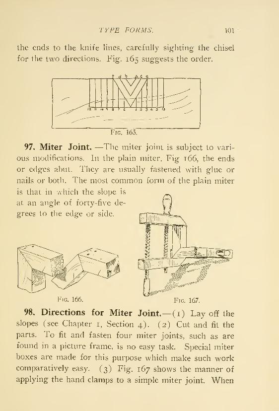
TYPE FORMS. 101
the ends to the knife Hnes, carefully sighting the chisel
for the two directions. Fig. 165 suggests the order.
Fig. 165.
97. Miter Joint, —The miter joint is subject to vari-
ous modifications. In the plain miter, Fig 166, the ends
or edges abut. They are usually fastened with glue or
nails or both. The most common form of the plain miter
is that in which the slope is
at an angle of forty-five de-
grees to the edge or side.
Fro. 166. Fig. 167.
98, Directions for Miter Joint,— (i) Lay off the
slopes (see Chapter i, Section 4). (2) Cut and fit the
parts. To fit and fasten four miter joints, such as are
found in a picture frame, is no easy task. Special miter
boxes are made for this purpose which make such workcomparatively easy. (3) Fig. 167 shows the manner of
applying the hand clamps to a simple miter joint. When
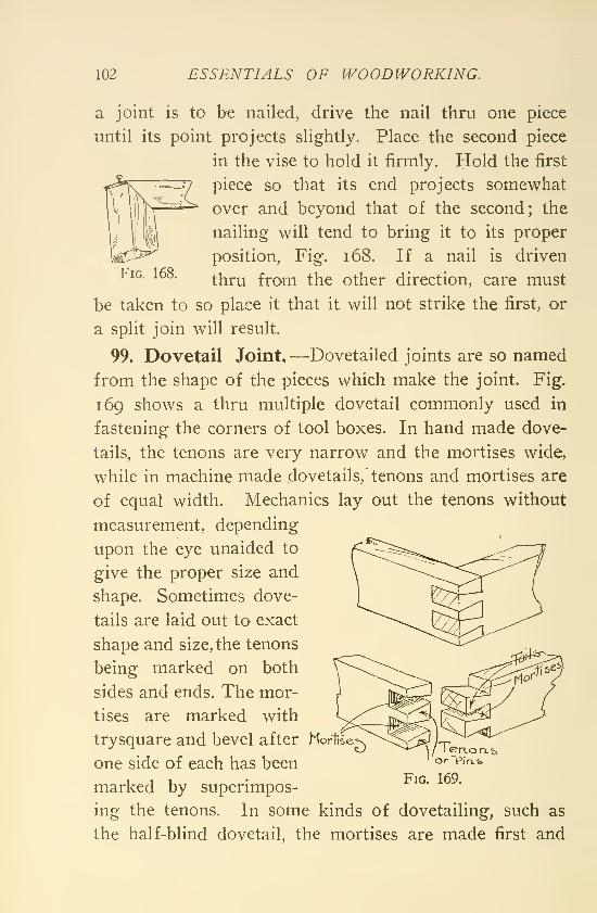
102 ESSENTIALS OF WOODWORKING.
Fig. 168.
a joint is to be nailed, drive the nail thru one piece
until its point projects slightly. Place the second piece
in the vise to hold it firmly. Hold the first
piece so that its end projects somewhat
over and beyond that of the second; the
nailing will tend to bring it to its proper
position, Fig. i68. If a nail is driven
thru from the other direction, care must
be taken to so place it that it will not strike the first, or
a split join will result.
99. Dovetail Joint,—Dovetailed joints are so named
from the shape of the pieces which make the joint. Fig.
169 shows a thru multiple dovetail commonly used in
fastening the corners of tool boxes. In hand made dove-
tails, the tenons are very narrow and the mortises wide,
while in machine made dovetails,' tenons and mortises are
of equal width. Mechanics lay out the tenons without
measurement, depending
upon the eye unaided to
give the proper size and
shape. Sometimes dove-
tails are laid out to exact
shape and size, the tenons
being marked on both
sides and ends. The mor-
tises are marked with
trysquare and bevel after Mortle<N^"
one side of each has been,11. . Fig. 169.
marked by superimpos-
ing the tenons. In some kinds of dovetailing, such as
the half-blind dovetail, the mortises are made first and
Tertomb
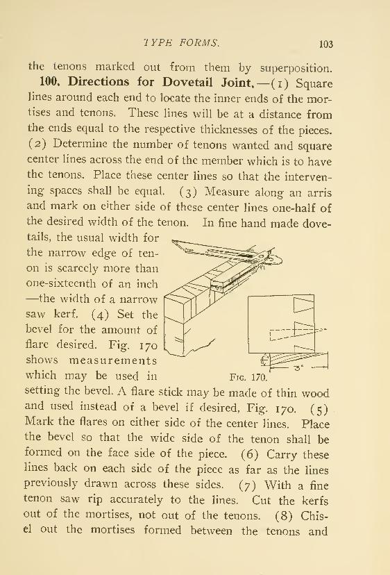
lYPE FORMS. 103
the tenons marked out from them by superposition.
100, Directions for Dovetail Joint,— (i) Squarelines around each end to locate the inner ends of the mor-tises and tenons. These lines will be at a distance fromthe ends equal to the respective thicknesses of the pieces.
(2) Determine the number of tenons wanted and square
center lines across the end of the member which is to havethe tenons. Place these center lines so that the interven-
ing spaces shall be equal. (3) Measure along an arris
and mark on either side of these center lines one-half of
the desired width of the tenon. In fine hand made dove-
tails, the usual width for
the narrow edge of ten-
on is scarcely more than
one-sixteenth of an inch
—the width of a narrow
saw kerf. (4) Set the
bevel for the amount of
flare desired. Fig. 170
shows measurementswhich may be used in Fig. 170.
setting the bevel. A flare stick may be made of thin woodand used instead of a bevel if desired, Fig. 170. (5)Mark the flares on either side of the center lines. Racethe bevel so that the wide side of the tenon shall beformed on the face side of the piece. (6) Carry these
lines back on each side of the piece as far as the lines
previously drawn across these sides. (7) With a fine
tenon saw rip accurately to the lines. Cut the kerfs
out of the mortises, not out of the tenons. (8) Chis-
el out the mortises formed between the tenons and
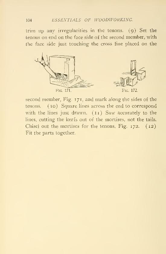
104 ESSENTIALS OF WOODWORKING.
trim up any irregularities in the tenons. (9) Set the
tenons on end on the face side of the second member, with
the face side just touching the cross line placed on the
Fig. 171. Fig. 172.
second member, Fig. 171, and mark along the sides of the
tenons. (10) Square lines across the end to correspond
with the lines just drawn. (11) Saw accurately to the
lines, cutting the kerfs out of the mortises, not the tails.
Chisel out the mortises for the tenons, Fig. 172. (12)
Fit the parts together.
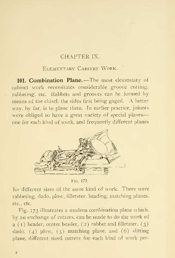
CHAPTER IX.
Elementary Cabinet Work.
101. Combination Plane.—The most elementary of
cabinet work necessitates considerable groove cutting,
rabbeting, etc. Rabbets and grooves can be formed by
means of the chisel, the sides first being gaged. A better
way, by far, is to plane them. In earlier practice, joiners
were obliged to have a great variety of special planes
—
one for each kind of work, and frecjuently different planes
Fig. 173.
for different sizes of the same kind of work. There were
rabbeting, dado, plow, filletster, beading, matching planes,
etc., etc.
Fig. 173 illustrates a modern combination plane which,
by an exchange of cutters, can be made to do the work of
a (i) header, center header, (2) rabbet and filletster, (3)
dado, (4) plow, (5) matching plane, and (6) slitting
plane, different sized cutters for each kind of work per-
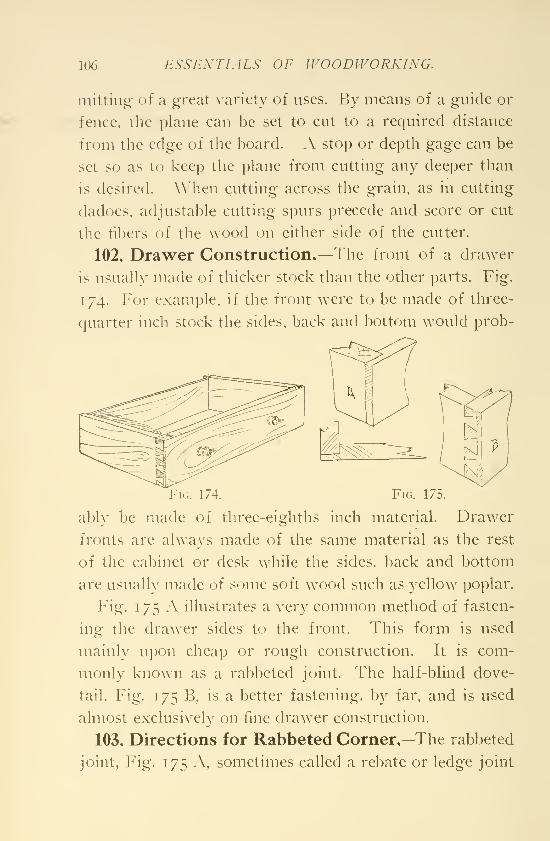
106 ESSENTIALS OF WOODWORKING.
mitting of a great variety of uses. By means of a guide or
fence, the plane can be set to cut to a required distance
from the edge of the board. A stop or depth gage can be
set so as to keep the plane from cutting any deeper than
is desired. \Mien cutting across the grain, as in cutting
dadoes, adjustable cutting spurs precede and score or cut
the fibers of the wood on either side of the cutter.
102, Drawer Construction,—11ie front of a drawer
is usually made of thicker stock than the other parts. Fig.
174. For example, if the front were to be made of three-
quarter inch stock the sides, back and bottom would prob-
FiG. 174. Fig. 175.
ably be made of three-eighths inch material. Drawer
fronts are always made of the same material as the rest
of the cabinet or desk while the sides, back and bottom
are usually made of some soft wood such as yellow poplar.
Fig. 1 75 A illustrates a very common method of fasten-
ing the drawer sides to the front. This form is used
mainly u])on cheap or rough construction. It is com-
monly known as a rabbeted joint. The half-blind dove-
tail, Fig. 175 B, is a better fastening, by far, and is used
almost exclusively on fine drawer construction.
103. Directions for Rabbeted Corner,—The rabbeted
joint, Fig. 175 A, sometimes called a rebate or ledge joint
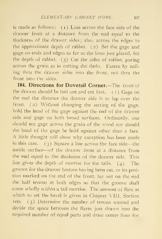
ELEMENTARY CABINET WORK. 107
is made as follows : ( i ) Line across the face side of the
drawer front at a distance from the end equal to the
thickness of the drawer sides; also, across the edges to
the approximate depth of rabbet. (2) Set the gage and
gage on ends and edges as far as the lines just placed, for
the depth of rabbet. (3) Cut the sides of rabbet, paring
across the grain as in cutting the dado. Fasten by nail-
ing thru the drawer sides into the front, not thru the
front into the sides.
104. Directions for Dovetail Corner,—The front of
the drawer should be laid out and cut first. ( i ) Gage on
the end the distance the drawer side is to lap over the
front. (2) Without changing the setting of the gage,
hold the head of the gage against the end of the drawer
side and gage on both broad surfaces. Ordinarily, one
should not gage across the grain of the wood nor should
the head of the gage be held against other than a face.
A little thought will show why exception has been madein this case. (3) Square a line across the face side—the
inside surface—of the drawer front at a distance fromthe end equal to the thickness of the drawer side. This
line gives the depth of mortise for the tails. (4) Thegroove for the drawer bottom having been cut, or its posi-
tion marked on the end of the front, lay out on the end
the half tenons at both edges so that the groove shall
come wholly within a tail mortise. The amount of flare at
which to set the bevel is given in Chapter VIII, Section
100. (5) Determine the number of tenons wanted anddivide the space between the flares just drawn into the
required number of equal parts and draw center lines for
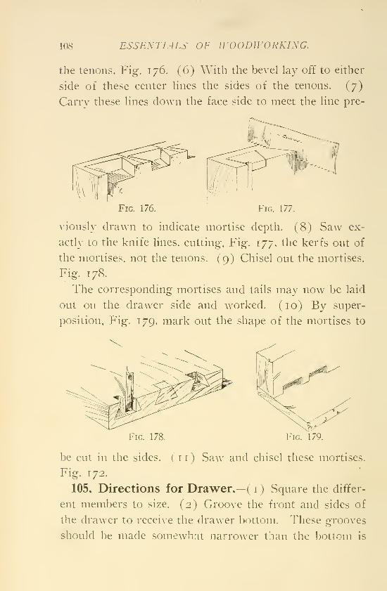
108 ESSENTIALS OF WOODWORKING.
the tenons, Fig. 176. (6) With the bevel lay off to either
side of these center lines the sides of the tenons. (7)
Carry these lines down the face side to meet the line pre-
FiG. 176. Fig. 177.
^•jously drawn to indicate mortise depth. (8) Saw ex-
actly to the knife lines, cutting. Fig. 177, the kerfs out of
the mortises, not the tenons. (9) Chisel out the mortises.
Fig. 178.
The corresponding mortises and tails may now be laid
out on the drawer side and w^orked. (10) By super-
position, Fig. 179, mark out the shape of the mortises to
Fig. 178. Fig. 179.
be cut in the sides. { 11 ) Saw and chisel these mortises.
Fig. 172.
105, Directions for Drawer.— ( i ) Square the dififer-
ent members to size. (2) Groove the front and sides of
the drawer to receive the drawer bottom. These o-rooves
should be made somewhat narrower than the bottom is
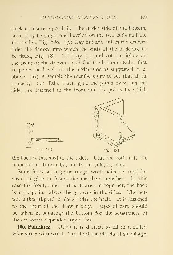
ELEMENTARY CABINET WORK. 109
thick to insure a good fit. The under side of the bottom,
later, may be gaged and beveled on the two ends and tlie
front edge, Fig. i8o. (3) Lay out and cut in the drawer
sides the dadoes into which the ends of the back are to
be fitted, Fig. 181. (4) Lay out and cut the joints on
the front of the drawer. ( 5 ) Get the bottom, ready ; that
is, plane the bevels on the under side as suggested in 2,
above. (6) Assemble the members dry to see that all fit
properly. (7) Take apart; glue the joints by which the
sides are fastened to the front and the joints by which
Fig. 180. Fig. 181.
the back is fastened to the sides. Glue tbe bottom to tlie
front of the drawer but not to the sides or back.
Sometimes on large or rough work nails are used in-
stead of glue to fasten the members together. In this
case the front, sides and back are put together, the back
being kept just above the grooves in the sides. The bot-
tim is then slipped in place under the back. It is fastened
to the front of the drawer only. Especial care should
be taken in squaring the bottom for the squareness of
the drawer is dependent upon this.
106. Paneling.—Often it is desired to fill in a rather
wide space with wood. To offset the effects of shrinkage,
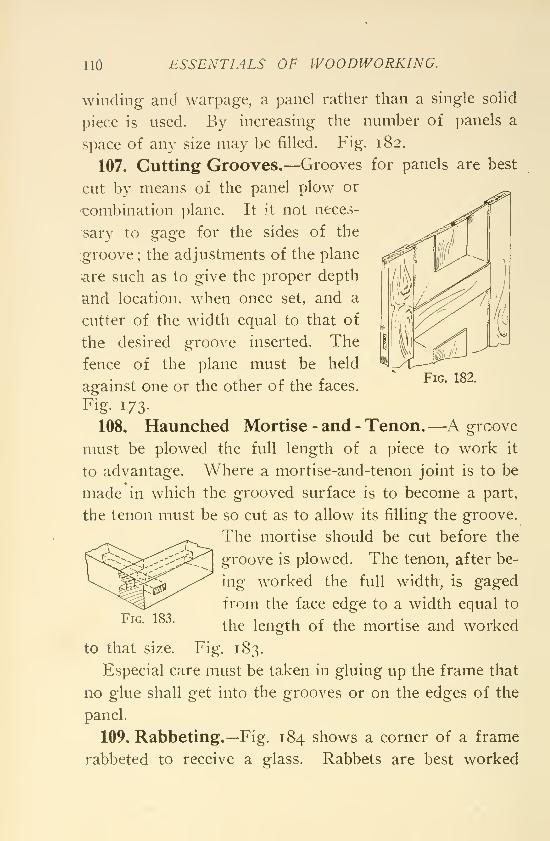
iio ESSENTIALS OF WOODWORKING.
Fig. 182.
winding and warpage, a panel rather than a single solid
piece is used. By increasing the number of panels a
space of any size may be filled. Fig. 182.
107, Cutting Grooves,—Grooves for panels are best
cut by means of the panel plow or
combination plane. It it not neces-
sary to gage for the sides of the
[groove ; the adjustments of the plane
are such as to give the proper depth
and location, when once set, and a
cutter of the width equal to that of
the desired groove inserted. The
fence of the plane must be held
against one or the other of the faces.
Fig- 173-
108, Haunched Mortise - and - Tenon,—A groove
must be plowed the full length of a piece to work it
to advantage. Where a mortise-and-tenon joint is to be
made in which the grooved surface is to become a part,
the tenon must be so cut as to allow its filling the groove.
The mortise should be cut before the
groove is plowed. The tenon, after be-
ing worked the full width, is gaged
from the face edge to a width equal to
the length of the mortise and worked
to that size. Fig. 183.
Especial care must be taken in gluing up the frame that
no glue shall get into the grooves or on the edges of the
panel.
109, Rabbeting,—Fig. 184 shows a corner of a frame
rabbeted to receive a glass. Rabbets are best worked
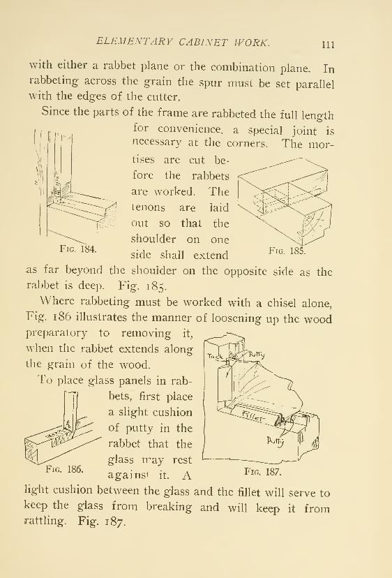
ELEMENTARY CABINET WORK. Ill
Fig. 184. Fig. 185.
with either a rabbet plane or the combination plane. Inrabbeting- across the grain the spur must be set parallel
with the edges of the cutter.
Since the parts of the frame are rabbeted the full length
for convenience, a special joint is
necessary at the corners. The mor-
tises are cut be-
fore the rabbets
are worked. The
tenons are laid
out so that the
shoulder on one
side shall extend
as far beyond the shoulder on the opposite side as the
rabbet is deep. Fig. 185.
Where rabbeting must be worked with a chisel alone,
Fig. 186 illustrates the manner of loosening up the woodpreparatory to removing it,
when the rabbet extends along
the grain of the wood.
To place glass panels in rab-
bets, first place
a slight cushion
of putty in the
rabbet that the
glass may rest
against it. Alight cushion between the glass and the fillet will serve to
keep the glass from breaking and will keep it fromrattling. Fig. 187.
Fig. 186. Fig. 187.
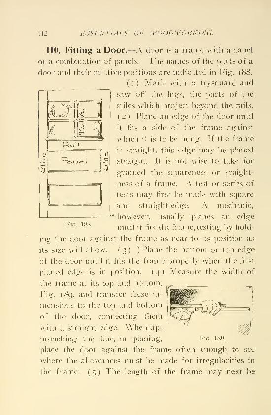
112 liSSENTJ.lLS 01' WOODWORKING.
lii
Tioil
l^ccSO«
110, Fitting a Door,—A door is a frame with a panel
or a combination of jianels. The names of the parts of a
door and their relative positions are indicated in Fig. i88.
( I ) Mark with a trysquare and
saw off tlie higs, the parts of the
stiles which project beyond the rails.
(2) Plane an edge of the door nntil
it fits a side of the frame against
which it is to be hung. If the frame
is straight, this edge may be ]>laned
straight. It is not wise to take for
granted the squareness or sraight-
ness of a frame. A test or series of
tests may first be made with square
and straight-edge. A mechanic,
'^liowevei', usually planes an edge
until it fits the frame, testing by hold-
ing- the door against the frame as near to its position as
its size will allow. (3) ) Plane the bottom or top edge
of the door until it fits the frame properly when the first
planed edge is in position. (4) Meastu-c the width of
the frame at its top and bottom,
Fig. 189, and transfer these di-
mensions to the top and bottom
of the door, connecting them
with a straight edge. When ap-
proaching the line, in planing, I^c. 189.
place the door against the frame often enough to see
where the allowances must be made for irregularities in
the frame. (5) The length of the frame may next be
Fjg. 188.
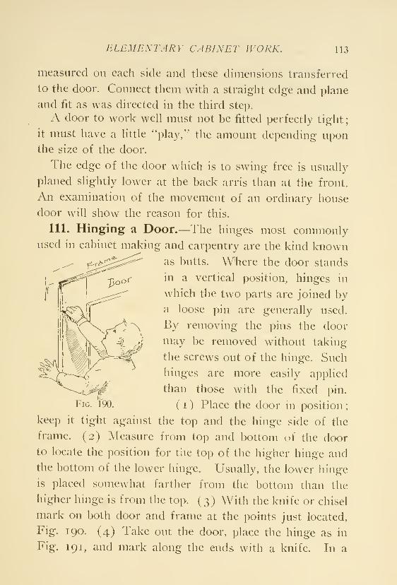
ELEMENTARY CABINET WORK. 113
measured on each side and these dimensions transferred
to the door. Connect them with a straight edge and plane
and fit as was directed in the third step.
A door to work well must not be fitted perfectly tight
;
it must have a Httle ''play," the amount depending uponthe size of the door.
The edge of the door which is to swing free is usually
planed slightly lower at the back arris than at the front.
An examination of the movement of an ordinary house
door will show the reason for this.
111. Hinging a Door.—The hinges most commonlyused in cabinet making and carpentry are the kind known
as butts. Where the door stands
in a vertical position, hinges in
,w^hich the two parts are joined by
a loose pin are generally used.
By removing the pins the door
may be removed without taking
the screws out of the hinge. Such
hinges are more easily applied
than those with the fixed \m\.
Fig. foo. ( i ) Place the door in position;
keep it tight against the top and the hinge side of the
frame. (2) Measure from top and bottom of the door
to locate the position for the top of the higher hinge and
the bottom of the lower hinge. Usually, the lower hinge
is placed somewhat farther froui the bottom than the
higher hinge is from the top. (3) With the knife or chisel
mark on both door and frame at the points just located,
Fig. 190. (4) Take out the door, place the hinge as in
Fig. 191, and mark along the ends with a knife. In a
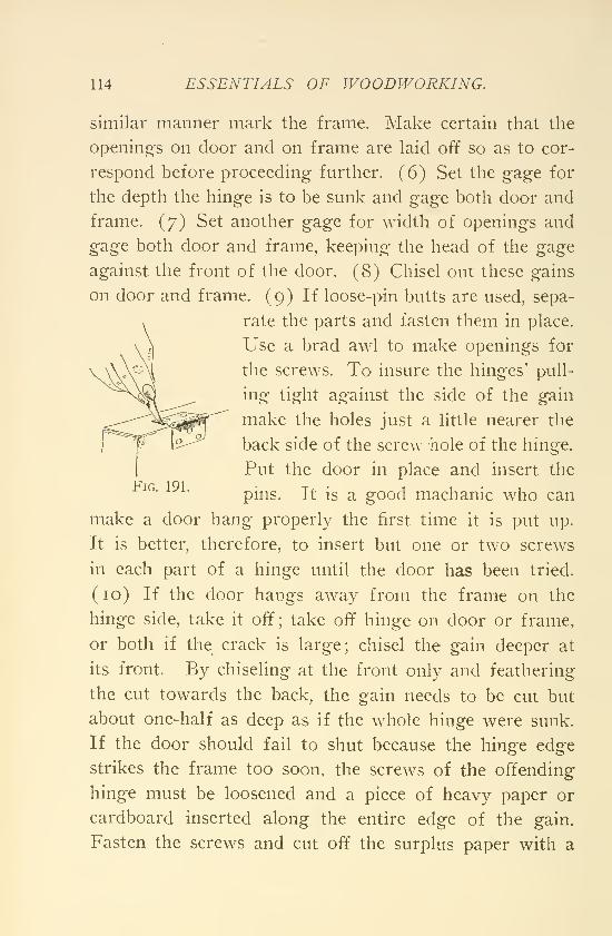
114 ESSENTIALS OF WOODWORKING.
similar manner mark the frame. Make certain that the
openings on door and on frame are laid off so as to cor-
respond before proceeding further. (6) Set the gage for
the depth the hinge is to be sunk and gage both door and
frame. (7) Set another gage for width of openings and
gage both door and frame, keeping the head of the gage
against the front of the door. (8) Chisel out these gains
on door and frame. (9) If loose-pin butts are used, sepa-
rate the parts and fasten them in place.
Use a brad awl to make openings for
the screws. To insure the hinges' pull-
ing tight against the side of the gain
make the holes just a little nearer the
back side of the screw hole of the hinge.
Put the door in place and insert the"Pjp 1Q1 . .
pms. It is a good machanic who can
make a door hang properly the first time it is put up.
It is better, therefore, to insert but one or two screws
in each part of a hinge until the door has been tried.
(10) If the door hangs away from the frame on the
hinge side, take it off; take off hinge on door or frame,
or both if the crack is large; chisel the gain deeper at
its front. By chiseling at the front only and feathering
the cut towards the back, the gain needs to be cut but
about one-half as deep as if the whole hinge were sunk.
If the door should fail to shut because the hinge edge
strikes the frame too soon, the screws of the offending
hinge must be loosened and a piece of heavy paper or
cardboard inserted along the entire edge of the gain.
Fasten the screws and cut off the surplus paper with a
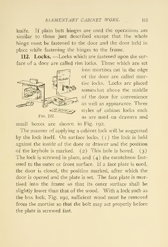
ELEMENTARY CABINET WORK. 115
Fig. 192.
knife. If plain butt hinges are used the operations are
similar to those just described except that the whole
hinge must be fastened to the door and the door held in
place while fastening the hinges to the frame.
112. Locks, —Locks which are fastened upon the sur-
face of a door are called rim locks. Those which are set
into mortises cut in the edge
of the door are called mor-
tise locks. Locks are placed
somewhat above the middle
of the door for convenience
as well as appearance. Three
styles of cabinet locks such
as are used on drawers and
small boxes are shown in Fig. 192.
The manner of applying^ a cabinet lock will be suggested
by the lock itself. On surface locks, ( i) the lock is held
against the inside of the door or drawer and the position
of the keyhole is marked. (2) This hole is bored. (3)
The lock is screwed in place, and (4) the escutcheon fast-
ened to the outer or front surface. If a face plate is used,
the door is closed, the position marked, after which the
door is opened and the plate is set. The face plate is mor-
tised into the frame so that its outer surface shall be
slightly lower than that of the wood. With a lock such as
the box lock. Fig. 192, sufficient wood must be removed
from the mortise so that the bolt may act properly before
the plate is screwed fast.
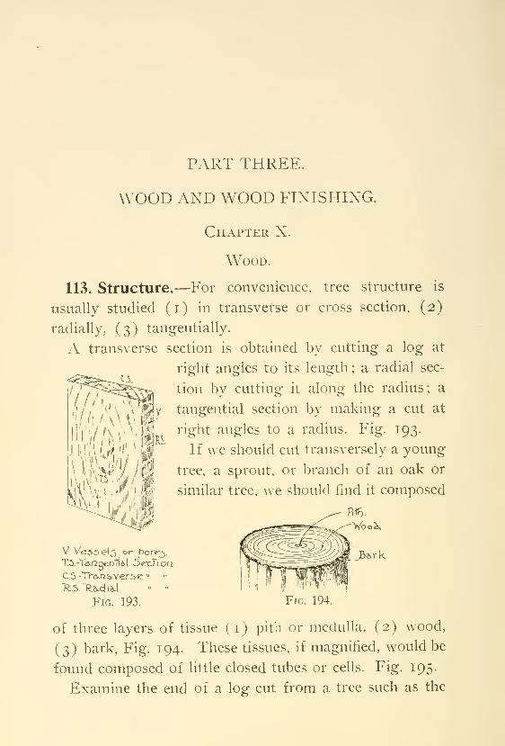
PART THREE.
WOOD AND WOOD FINISHING.
Chapter X.
Wood.
113. Structure,—For convenience, tree structure is
usually studied (i) in transverse or cross section, (2)
radially, (3) tangentially.
A transverse section is obtained by cutting a log at
right angles to its length ; a radial sec-
tion by cutting it along the radius; a
tangential section by making a cut at
right angles to a radius. Fig. 193.
If we should cut transversely a young
tree, a sprout, or branch of an oak or
similar tree, we should find it composed
V Vessel^ or porer^.
T5.-TAageo1iA-l ^ecX\on
C5 -Tr6~n.sYer6e "
R..5 "Resell ^1 " "
Fig. 193.
B^rk
Fig. 194.
of three layers of tissue (i) pith or medulla, (2) wood,
(3) bark. Fig. 194. These tissues, if magnified, would be
found composed of little closed tubes or cells. Fig. 195.
Examine the end of a log cut from a tree such as the
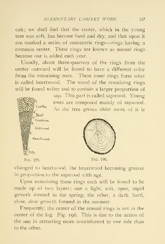
ELEMENTARY CABINET WORK. 117
oak; we shall find that the center, which in the young
tree was soft, has become hard and dry, and that upon it
are marked a series of concentric rings—rings having a
common center. These rings are known as annual rings
because one is added each year.
Usually, about three-quarters of the rings from the
center outward will be found to have a different color
from the remaining ones. These inner rings form what
is called heartwood. The wood of the remaining rings
will be found softer and to contain a larger proportion of
sap. This part is called sapwood. Youngtrees are composed mainly of sapwood.
Cortex
Ba-sf
As the tree grows older more of it is
^dvj:?woo<f.
He<ivrfv»'oocl.
changed to heartwood, the heartwood becoming greater
in proportion to the sapwood with age.
Upon examining these rings each will be found to be
made up of two layers; one a light, soft, open, rapid
growth formed in the spring, the other, a dark, hard,
close, slow growth formed in the summer.
Frequently, the center of the annual rings is not in the
center of the log. Fig. 196. This is due to the action of
the sun in attracting more nourishment to one side than
to the other.
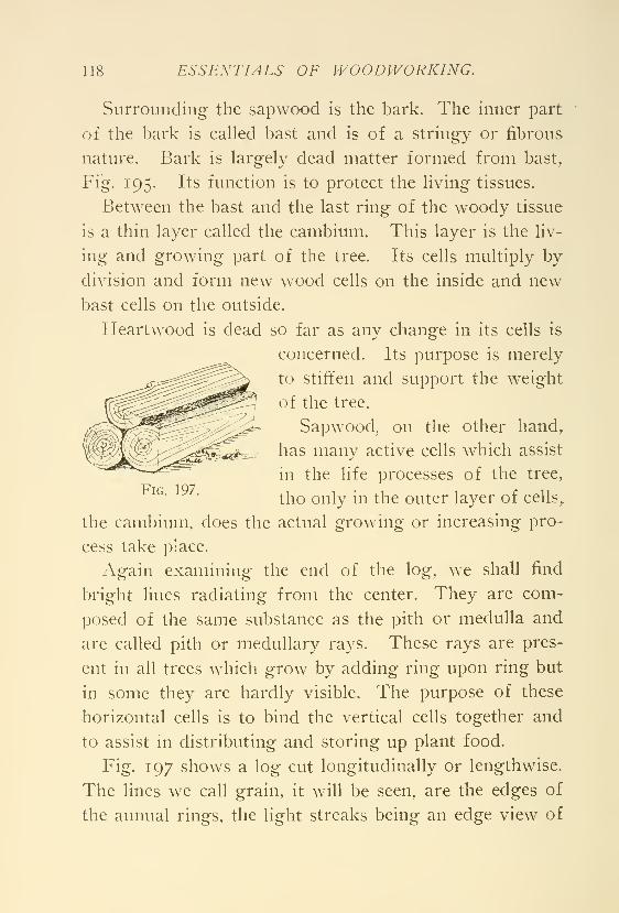
118 ESSENTIALS OF WOODWORKING.
Surrounding the sapwood is the bark. The inner part
of the bark is called bast and is of a stringy or fibrous
nature. Bark is largely dead matter formed from bast,
Fig. 195. Its function is to protect the living tissues.
Between the bast and the last ring of the woody tissue
is a thin layer called the cambium. This layer is the liv-
ing and growing part of the tree. Its cells multiply by
division and form new wood cells on the inside and new
bast cells on the outside.
Heartwood is dead so far as any change in its cells is
concerned. Its purpose is merely
to stiffen and support the weight
of the tree,
Sapwood, on the other hand,
W^¥^-^'C^^^^^^^^s=r has many active cells which assist
in the life processes of the tree,
^*^"
tho only in the outer layer of cells,
the cambium, does the actual growing or increasing pro-
cess take place.
Again examining the end of the log, we shall find
bright lines radiating from the center. They are com-
posed of the same substance as the pith or medulla and
are called pith or medullary rays. These rays are pres-
ent in all trees which grow by adding ring upon ring but
in some they are hardly visible. The purpose of these
horizontal cells is to bind the vertical cells together and
to assist in distributing and storing up plant food.
Fig. 197 shows a log cut longitudinally or lengthwise.
The lines we call grain, it will be seen, are the edges of
the annual rings, the light streaks being an edge view of
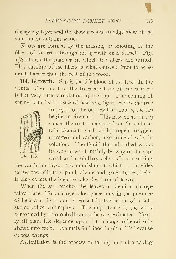
ELEMENTARY CABINET WORK. 119
the spring layer and the dark streaks an edge view of the
summer or autumn wood.
Knots are formed by the massing or knotting of the
fibers of the tree through the growth of a branch. Fig.
1^8 shows the manner in which the fibers are turned.
This packing of the fibers is what causes a knot to be so
much harder than the rest of the wood.
114, Growth.—Sap is the life blood of the tree. In the
winter when most of the trees are bare of leaves there
is but very little circulation of the sap. Xhe coming of
spring with its increase of heat and light, causes the tree
to begin to take on new life ; that is, the sap
begins to circulate. This movement of sap
causes the roots to absorb from the soil cer-
tain elements such as hydrogen, oxygen,
nitrogen and carbon, also mineral salts in
solution. The liquid thus absorbed works
its way upward, mainly by way of the sap-
wood and medullary cells. Upon reaching
the cambium layer, the nourishment which it provides
causes the cells to expand, divide and generate new cells.
It also causes the buds to take the form of leaves.
When the sap reaches the leaves a chemical change
takes place. This change takes place only in the presence
of heat and light, and is caused by the action of a sub-
stance called chlorophyll. The importance of the workperformed by chlorophyll cannot be overestimated. Near-
ly all plant life depends upon it to change mineral sub-
stance into food. Animals find food in plant life because
of this change.
Assimilation is the process of taking up and breaking
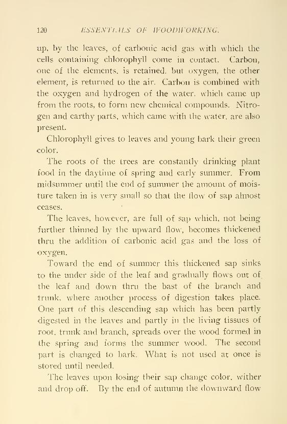
120 ESSENTIALS OF WOODWORKING.
up, by the leaves, of carbonic acid gas with which the
cells containing chlorophyll come in contact. Carbon,
one of the elements, is retained, but oxygen, the other
element, is returned to the air. Carbon is combined with
the oxygen and hydrogen of the water, which came up
from the roots, to form new chemical compounds. Nitro-
gen and earthy parts, w^hich came with the water, are also
present.
Chlorophyll gives to leaves and young bark their green
color.
The roots of the trees are constantly drinking plant
food in the daytime of spring and early summer. From
midsummer until the end of summer the amount of mois-
ture taken in is very small so that the flow of sap almost
ceases.
The leaves, however, are full of sap which, not being
further thinned by the upward flow% becomes thickened
thru the addition of carbonic acid gas and the loss of
oxygen.
Toward the end of summer this thickened sap sinks
to the under side of the leaf and gradually flows out of
the leaf and down thru the bast of the branch and
trunk, where another process of digestion takes place.
One part of this descending sap which has been partly
digested in the leaves and partly in the living tissues of
root, trunk and branch, spreads over the wood formed in
the spring and forms the summer wood. The second
part is changed to bark. What is not used at once is
stored until needed.
The leaves upon losing their sap change color, wither
and drop oft*. By the end of autumn the downward flow
ELEMENTARY CABINET WORK. 121
of changed sap from the leaves is completed and the tree
has prepared itself for the coming winter.
It must be remembered that the foregoing changes are
made gradually. After the first movement of the sap in
the early spring has nourished the buds into leaves of a
size sufficient to perform work, there begins a downward
movement of food materials—slight at first, to be sure,
but ever increasing in volume until the leaves are doing
full duty. We may say, therefore, that the upward move-
ment of the sap thru the sapwood and the downward flow
of food materials thru the bast takes place at the same
time, their changes being of relative volumes rather than
oi time.
115. Respiration and Transpiration.—Plants, like
animals, breathe ; like animals they breathe in oxygen and
breath out carbonic acid gas. Respiration which is but
another name for breathing, goes on day and night, but
is far less active than assimilation, which takes place only
during the day. Consequently more carbonic acid gas is
taken in than is given out except at night when, to a slight
extent, the reverse takes place, small quantities of car-
bonic acid gas being given off and oxygen taken in.
Very small openings in the bark called lenticles, furnish
breathing places. Oxygen is also taken in thru the
leaves.
Transpiration is the evaporation of water from all parts
of the tree above ground, principally from the leaves.
The amount of water absorbed by the roots is greatly
in excess of what is needed. That fresh supplies of
earthy matter may reach the leaves, the excess of water
must be got rid of. In trees with very thick bark, tran-
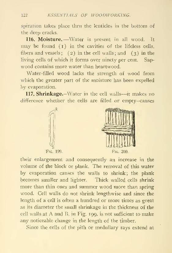
122 ESSENTIALS OF WOODWORKING.
spiration takes place thru the lenticles in the bottom of
the deep cracks.
116. Moisture.—Water is present in all wood. It
may be found (i) in the cavities of the lifeless cells,
fibers and vessels; (2) in the cell walls ; and (3) in the
living cells of which it forms over ninety per cent. Sap-
w^ood contains more water than heartwood.
Water-filled wood lacks the strength of wood from
which the greater part of the moisture has been expelled
by evaporation.
117. Shrinkage,-Water in the cell walls—it makes no
difference whether the cells are filled or empty—causes
BFig. 199. Fig. 200.
their enlargement and consequently an increase in the
volume of the block or plank. The removal of this water
by evaporation causes the walls to shrink; the plank
becomes smaller and lighter. Thick walled cells shrink
more than thin ones and summer wood more than spring
wood. Cell walls do not shrink lengthwise and since the
length of a cell is often a hundred or more times as great
as its diameter the small shrinkage in the thickness of the
cell walls at A and B, in Fig. 199, is not sufficient to makeany noticeable change in the length of the timber.
Since the cells of the pith or medullary rays extend at
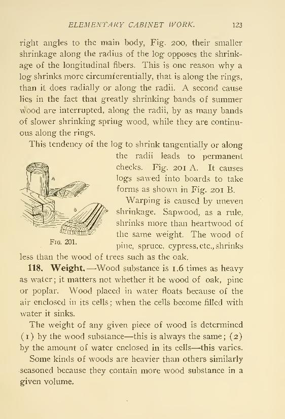
ELEMENTARY CABINET WORK. 123
right angles to the main body, Fig. 200, their smaller
shrinkage along the radius of the log opposes the shrink-
age of the longitudinal fibers. This is one reason why a
log shrinks more circumferentially, that is along the rings,
than it does radially or along the radii. A second cause
lies in the fact that greatly shrinking bands of summer
wood are interrupted, along the radii, by as many bands
of slower shrinking spring wood, while they are continu-
ous along the rings.
This tendency of the log to shrink tangentially or along
the radii leads to permanent
checks. Fig. 201 A. It causes
logs sawed into boards to take
forms as shown in Fig. 201 B.
Warping is caused by uneven
shrinkage. Sapwood, as a rule,
shrinks more than heartwood of
the same weight. The wood ofFig. 201. •
^ u • 1
pnie, spruce, cypress, etc., shrmks
less than the wood of trees such as the oak.
118, Weight,—Wood substance is 1.6 times as heavy
as water ; it matters not whether it be wood of oak, pine
or poplar. Wood placed in water floats because of the
air enclosed in its cells ; when the cells become filled with
water it sinks.
The weight of any given piece of wood is determined
( i) by the wood substance—this is always the same; (2)
by the amount of water enclosed in its cells—this varies.
Some kinds of woods are heavier than others similarly
seasoned because they contain more wood substance in a
given volume.
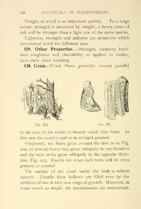
124 ESSENTIALS OF WOODWORKING.
Weight of wood is an important quality. To a large
extent, strength is measured by weight; a heavy piece of
oak will be stronger than a light one of the same species.
Lightness, strength and stiffness are properties which
recommend wood for different uses.
119, Other Properties,—Strength, elasticity, hard-
ness, toughness and cleavability as applied to timber,
have their usual meaning.
120, Grain,-Wood fibers generally extend parallel
Fig. 202. Fig. 203.
to the axis of the trunk or branch which they form. In
this case the wood is said to be straight grained.
Frequently, the fibers grow around the tree as in Fig.
202, or several layers may grow obliquely in one direction
and the next series grow obliquely in the opposite direc-
tion, Fig. 203. Boards cut from such trees will be cross
grained or twisted.
The surface of the wood under the bark is seldom
smooth. Usually these hollows are filled even by the
addition of one or two new rings of growth. However, in
some woods as maple, the unevennesses are maintained.
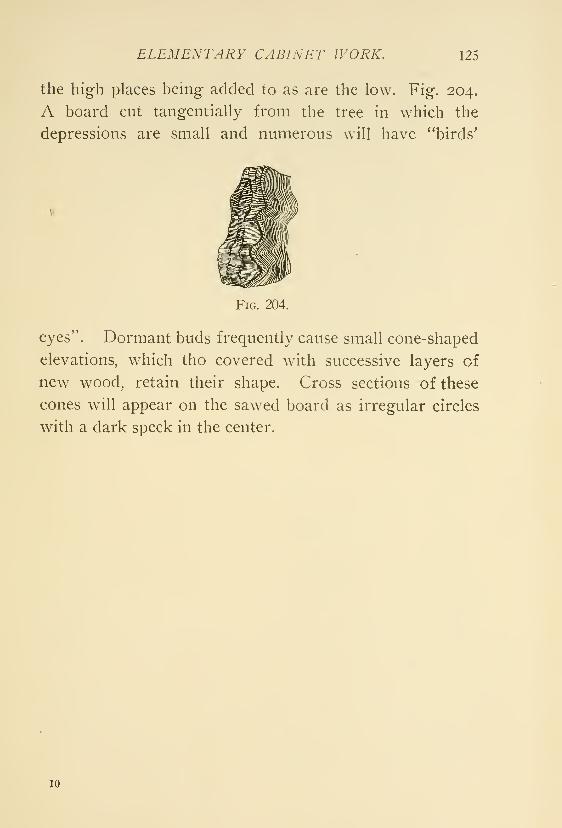
ELEMENTARY CABINET WORK. 125
the high places being added to as are the low. Fig. 204.
A board cut tangentially from the tree in which the
depressions are small and numerous will have *^birds'
Fig. 204.
eyes". Dormant buds frequently cause small cone-shaped
elevations, which tho covered with successive layers of
new wood, retain their shape. Cross sections of these
cones will appear on the sawed board as irregular circles
with a dark speck in the center.
10
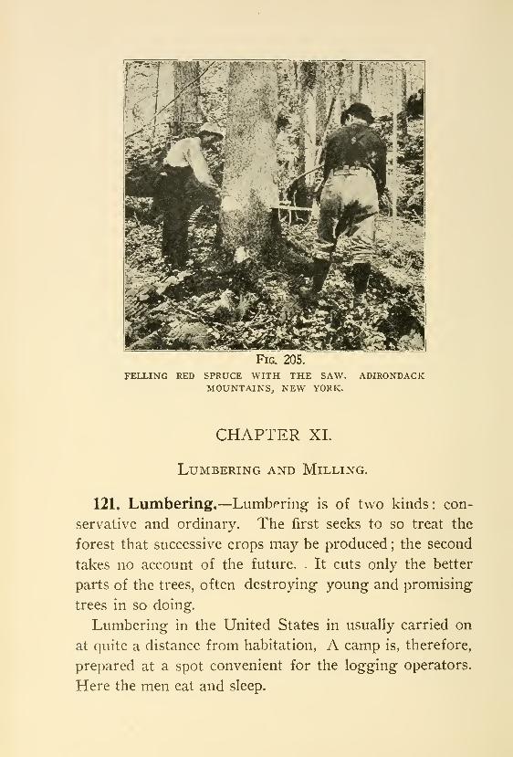
Fig. 205.
felling red spruce with the saw.mountains^ new york.
ADIRONDACK
CHAPTER XL
Lumbering and Milling.
121, Lumbering,—Lumbering is of two kinds : con-
servative and ordinary. The first seeks to so treat the
forest that successive crops may be produced ; the second
takes no account of the future. . It cuts only the better
parts of the trees, often destroying young and promising
trees in so doing.
Lumbering in the United States in usually carried on
at quite a distance from habitation, A camp is, therefore,
prepared at a spot convenient for the logging operators.
Here the men eat and sleep.
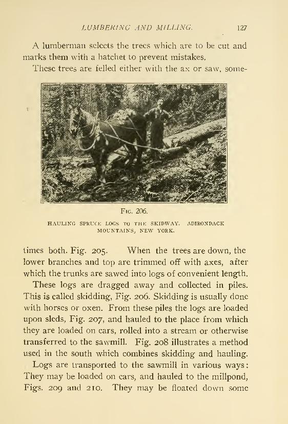
LUMBERING AND MILLING. 127
A lumberman selects the trees which are to be cut and
marks them with a hatchet to prevent mistakes.
These trees are felled either with the ax or saw, some-
FiG. 206.
HAULING SPRUCE LOGS TO THE SKIDWAY.MOUNTAINS,, NEW YORK.
ADIRONDACK
times both. Fig. 205. When the trees are down, the
lower branches and top are trimmed off with axes, after
which the trunks are sawed into logs of convenient length.
These logs are dragged away and collected in piles.
This is called skidding, Fig. 206. Skidding is usually done
with horses or oxen. From these piles the logs are loaded
upon sleds, Fig. 207, and hauled to the place from which
they are loaded on cars, rolled into a stream or otherwise
transferred to the sawmill. Fig. 208 illustrates a method
used in the south which combines skidding and hauling.
. Logs are transported to the sawmill in various ways:
They may be loaded on cars, and hauled to the millpond,
Figs. 209 and 210. They may be floated down some
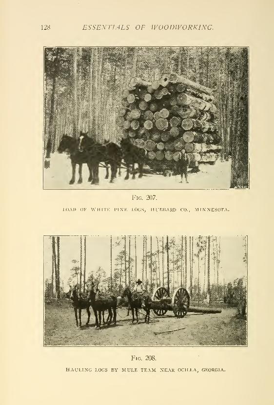
128 ESSENTIALS OF WOODWORKING.
Fig. 207.
load of white pine logs, hubbard co., minnesota.
Fig. 208.
hauling logs by mule team near ocilla, georgia.
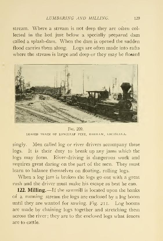
LUMBERING AND MILLING. 129
Stream. Where a stream is not deep they are often col-
lected in the bed just below a specially prepared damcalled a splash-dam. When the dam is opened the sudden
flood carries them along. Logs are often made into rafts
where the stream is large and deep or they may be floated
Fig. 209.
loaded train of longleaf pine, barham, louisiana.
singly. Men called log or river drivers accompany these
logs. It is their duty to break up any jams which the
logs may form. River-driving is dangerous work and
requires great daring on the part of the men. They must
learn to balance themselves on floating, rolling logs.
When a log jam is broken the logs go out with a great
rush and the driver must make his escape as best he can.
122. Milling.—If the sawmill is located upon the banks
of a running stream the logs are enclosed by a log boomuntil they are wanted for sawing. Fig. 211. Log booms
are made by chaining logs together and stretching them
across the river ; they are to the enclosed logs what fences
are to cattle.
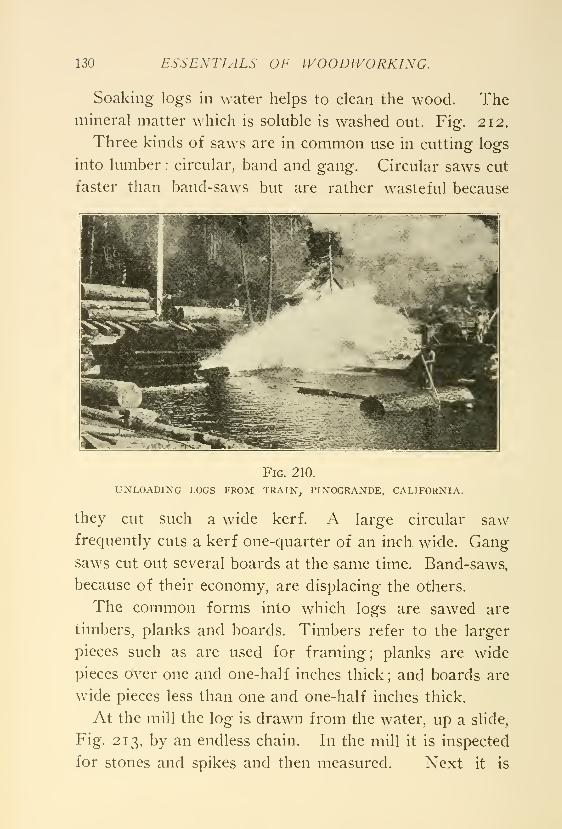
130 ESSENTIALS OF WOODWORKING.
Soaking logs in water helps to clean the wood. Themineral matter which is soluble is washed out. Fig. 212.
Three kinds of saws are in common use in cutting logs
into lumber : circular, band and gang. Circular saws cut
faster than band-saws but are rather wasteful because
Fig. 210.
unloading logs from train^ pinogrande, california.
they cut such a wide kerf. A large circular saw
frequently cuts a kerf one-quarter of an inch wide. Gangsaws cut out several boards at the same time. Band-saws,
because of their economy, are displacing the others.
The common forms into which logs are sawed are
timbers, planks and boards. Timbers refer to the larger
pieces such as are used for framing; planks are wide
pieces over one and one-half inches thick; and boards are
wide pieces less than one and one-half inches thick.
At the mill the log is drawn from the water, up a slide,
Fig. 213. by an endless chain. In the mill it is inspected
for stones and spikes and then measured. Next it is
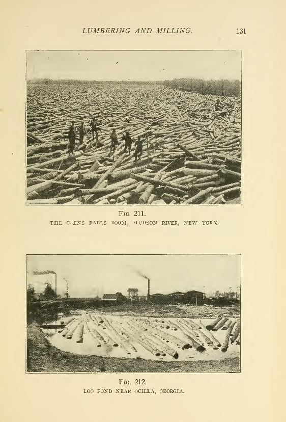
LUMBERING AND MILLING. 131
Fig. 211.
the glens falls boom, hudson river^ new york.
Fig. 212.
log pond near ocilla, georgia.
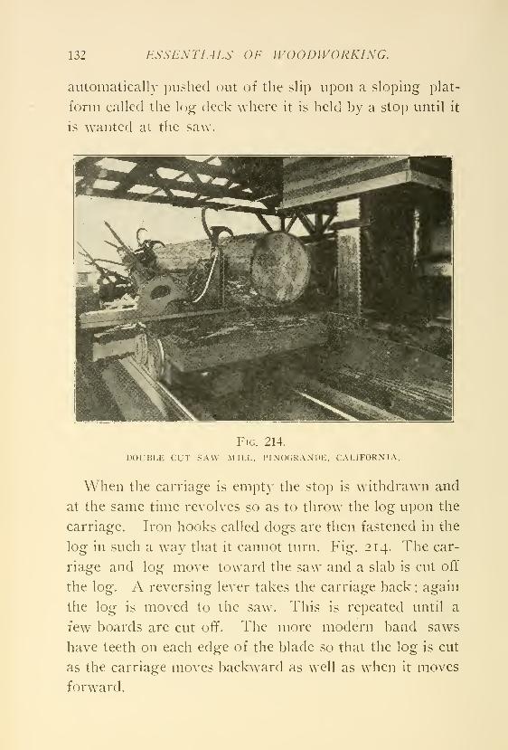
132 ESSENTIALS OF WOODWORKING.
automatically pushed out of the slip upon a sloping plat-
form called the log- deck where it is held by a stop until it
is wanted at the saw.
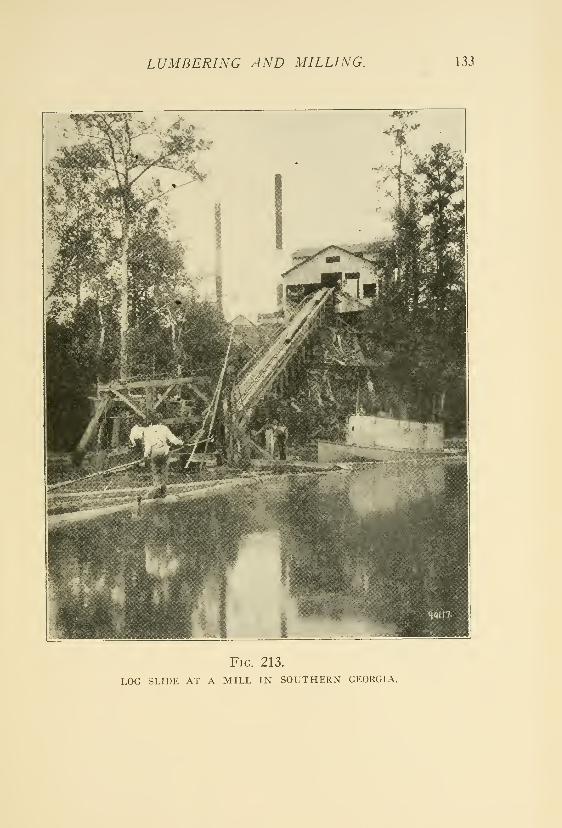
LUMBERING AND MILLING. 133
Fig. 213.
log slide at a mill in southern georgia.
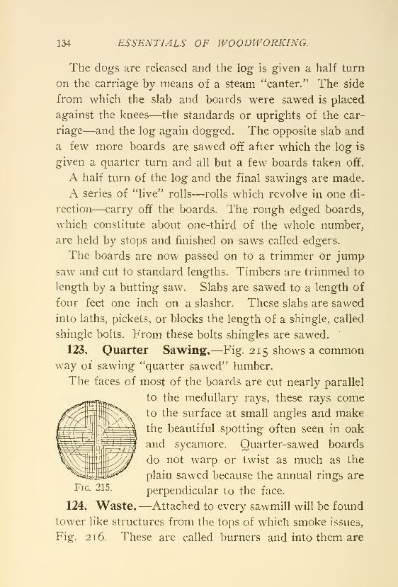
134 ESSENTIALS OF WOODWORKING.
The dogs are released and the log is given a half turn
on the carriage by means of a steam ''canter." The side
from which the slab and boards were sawed is placed
against the knees—the standards or uprights of the car-
riage—and the log again dogged. The opposite slab and
a few more boards are sawed off after which the log is
given a quarter turn and all but a few boards taken off.
A half turn of the log and the final sawings are made.
A series of ''live" rolls—rolls which revolve in one di-
rection—carry off the boards. The rough edged boards,
which constitute about one-third of the whole number,
are held by stops and finished on saws called edgers.
The boards are now passed on to a trimmer or jump
saw and cut to standard lengths. Timbers are trimmed to
length by a butting saw. Slabs are sawed to a length of
four feet one inch on a slasher. These slabs are sawed
into laths, pickets, or blocks the length of a shingle, called
shingle bolts. From these bolts shingles are sawed.
123. Quarter Sawing,—Fig. 215 shows a commonway of sawing "quarter sawed" lumber.
The faces of most of the boards are cut nearly parallel
to the medullary rays, these rays come
to the surface at small angles and make
the beautiful spotting often seen in oak
and sycamore. Quarter-sawed boards
do not warp or twist as much as the
plain sawed because the annual rings are
Fig. 215. perpendicular to the face.
124, Waste.—Attached to every sawmill will be found
tower like structures from the tops of which smoke issues,
Fig. 216. These are called burners and into them are
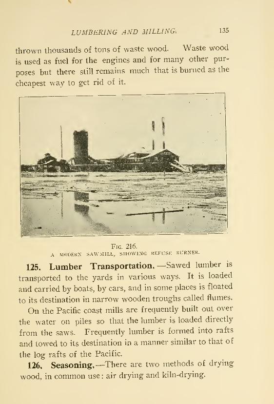
LUMBERING AND MILLING-. 135
thrown thousands of tons of waste wood. Waste wood
is used as fuel for the engines and for many other pur-
poses but there still remains much that is burned as the
cheapest way to get rid of it.
Fig. 216.
A MODERN SAWMILL, SHOWING REFUSE BURNER.
125. Lumber Transportation, —Sawed lumber is
transported to the yards in various ways. It is loaded
and carried by boats, by cars, and in some places is floated
to its destination in narrow wooden troughs called flumes.
On the Pacific coast mills are frequently built out over
the water on piles so that the lumber is loaded directly
from the saws. Frequently lumber is formed into rafts
and towed to its destination in a manner similar to that of
the log rafts of the Pacific.
126, Seasoning,—There are two methods of drying
wood, in common use : air drying and kiln-drying.
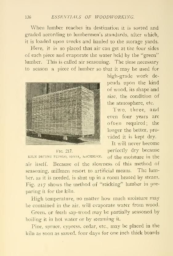
136 ESSENTIALS OF WOODWORKING.
When lumber reaches its destination it is sorted and
graded according to lumbermen's standards, after which,
it is loaded upon trucks and hauled to the storage yards.
Here, it is so placed that air can get at the four sides
of each piece and evaporate the water held by the ''green"
lumber. This is called air seasoning. The time necessary
to season a piece of lumber so that it may be used for
high-grade work de-
pends upon the kind
of wood, its shape and
size, the condition of
the atmosphere, etc.
Two, three, and
even four years are
often required; the
longer the better, pro-
vided it is kept dry.
It will never become
Fig. 217. perfectly dry because
KILN DRriNG TUPELO, IONIA,, MICHIGAN. q£ ^J^g mOlstUrC iu tllC
air itself. Because of the slowness of this method of
seasoning, millmen resort to artificial means. The lum-
ber, as it is needed, is shut up in a room heated by steam.
Fig. 217 shows the method of ''sticking" lumber in pre-
paring it for the kiln.
High temperature, no matter how much moisture may
be contained in the air, will evaporate water from wood.
Green, or fresh sap-wood may be partially seasoned by
boiling it in hot water or by steaming it.
Pine, spruce, cypress, cedar, etc., may be placed in the
kiln as soon as sawed, four days for one inch thick boards
LUMBERING AND MILLING. 137
being sufficient to dry them. Hard woods, such as oak,
maple, birch, etc., are usually allowed to ''air season" for
a period of from three to six months before being placed
in the kiln. Six to ten days additional kiln drying is
allowed them.
The usual temperature for kilns is from 158 to 180
degrees Fahr. Hardwoods lose moisture so slowly that
to place them in the kiln directly from the saw would
cause them to shrink very unevenly and hence make them
subject to serious ''checks".
Lumber is frequently steamed to prevent its checking
and "case hardening" while being kiln dryed.
127, Lumber Terms and Measurements,—"Clear"
lumber is lumber which is free from knots and sapwood.
"Dressed" lumber or "surfaced" or "sized" lumber
is lumber which has passed thru the planer.
The unit of measure is the board-foot which is one inch
thick and twelve inches square. Boards less than one
inch thick are sold by the square foot, face measure.
Shingles and lath are sold by the bundle. AToldings
are sold by "running" or lineal measure.
Prices are usually based upon the thousand feet ; thus,
200 feet, I St, clear, S2S, (sized or surfaced on two sides)
at $47 per M.
CHAPTER XII.
Common Woods.
128, Classification, —According to botanical class-
ification, woods belong to the Flowering Plants (Phan-
eroganiia). Classified further we have :
(i) Naked seeds (gymnosperms)
1. Palm ferns, etc. (cycadacese)
2. Joint firs (gnetacese)
3. Pines, firs, etc. (conifers)
(2) Fruits (angiosperms)
1. One-seed-leaf (monocotyledons)
(Bamboos, palms, grasses, etc.)
2. Two-seed-leaf (dicotyledon)
a. Herbs.
h. Broad-leafed trees,
(oak, ash, elm, etc.)
Conifers and broad-leaved trees are alike in that they
add a new layer of wood each year which covers the old
wood of root, trunk and branch. They are known as
exogens—outward growers.
In woods such as the palms, bamboos, and yuccas,
growth is made from within.
The new wood strands mingle with the old and cause
the cross sections to appear dotted, Fig. 218. Trees of
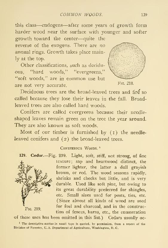
COMMON WOODS. 139
this class—endogens—after some years of growth form
harder wood near the surface with younger and softer
growth toward the center—quite the
reverse of the exogens. There are no
annual rings. Growth takes place main-
ly at the top.
Other classifications, such as decidu-
ous, "hard woods," "evergreens,"
"soft woods," are in common use butKir 218
are not very accurate.
Deciduous trees are the broad-leaved trees and ^ri so
called because they lose their leaves in the fall. Broad-
leaved trees are also called hard woods.
Conifers are called evergreens because their needle-
shaped leaves remain green on the tree the year around.
They are also known as soft woods.
Most of our timber is furnished by (i) the needle-
leaved conifers and (2) the broad-leaved trees.
Coniferous Woods. ^
129. Cedar.—Fig. 219. Light, soft, stiff, not strong, of fine
texture; sap and heartwood distinct, the
former lighter, the latter a dull grayish
brown, or red. The wood seasons rapidly,
shrinks and checks but little, and is very
durable. Used like soft pine, but owing to
its great durability preferred for shingles,
etc. Small sizes used for posts, ties, etc.
(Since almost all kinds of wood are used
V oirt for fuel and charcoal, and in the construc-FiG. 219. . , .
,
'
,
tion 01 fences, barns, etc., the enumeration
of these uses has been omitted in this list.) Cedars usually oc-
^ The descriptive matter in small type is quoted, by permission, from a report of the
Division of Forestry, U. S. Department of Agriculture, Washington, D. C.
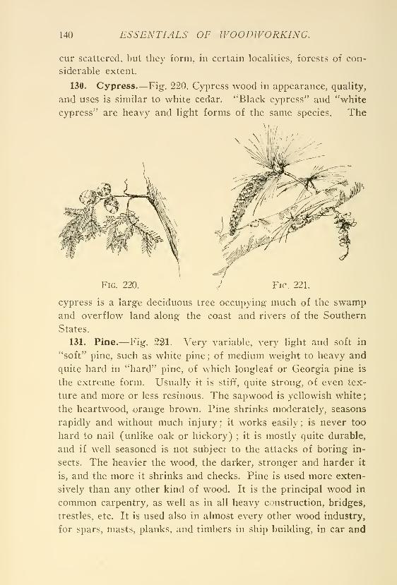
140 ESSENTIALS OF WOODWORKING.
cur scattered, but they form, in certain localities, forests of con-
siderable extent.
130. Cypress.—Fig. 220. Cypress wood in appearance, quality,
and uses is similar to white cedar, "Black cypress" and "white
cypress" are heavy and light forms of the same species. The
Fig. 220. Fir 221.
cypress is a large deciduous tree occupying- much of the swampand overflow land along the coast and rivers of the Southern
States.
131. Pine.—Fig. 221. Very variable, very light and soft in
"soft" pine, such as white pine ; of medium weight to heavy and
quite hard in "hard" pine, of which longleaf or Georgia pine is
the extreme form. Usually it is stiff, quite strong, of even tex-
ture and more or less resinous. The sapwood is yellowish white
;
the heartwood, orange brown. Pine shrinks moderately, seasons
rapidly and without much injury; it works easily; is never too
hard to nail (unlike oak or hickory) ; it is mostly quite durable,
and if well seasoned is not subject to the attacks of boring in-
sects. The heavier the wood, the darker, stronger and harder it
is, and the more it shrinks and checks. Pine is used more exten-
sively than any other kind of wood. It is the principal wood in
common carpentry, as well as in all heavy construction, bridges,
trestles, etc. It is used also in almost every other wood industry,
for spars, masts, planks, and timbers in ship building, in car and
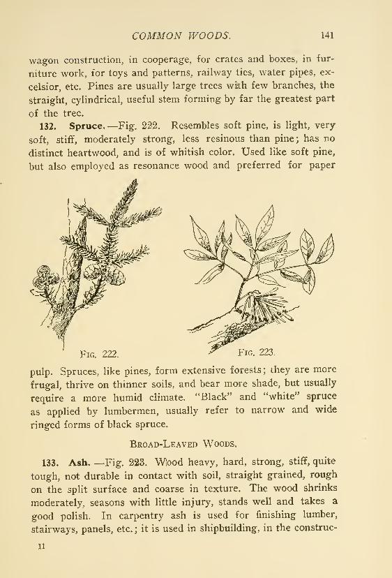
COMMON WOODS. 141
wagon construction, in cooperage, for crates and boxes, in fur-
niture work, for toys and patterns, railway ties, water pipes, ex-
celsior, etc. Pines are usually large trees with few branches, the
straight, cylindrical, useful stem forming by far the greatest part
of the tree.
132. Spruce.—Fig. 222. Resembles soft pine, is light, very
soft, stiff, moderately strong, less resinous than pine; has no
distinct heartwood, and is of whitish color. Used like soft pine,
but also employed as resonance wood and preferred for paper
Fig. 222. Fig. 223
pulp. Spruces, like pines, form extensive forests ; they are more
frugal, thrive on thinner soils, and bear more shade, but usually
require a more humid climate. "Black" and "white" spruce
as applied by lumbermen, usually refer to narrow and wide
ringed forms of black spruce.
Broad-Leaved Woods.
133. Ash. —Fig. 223. Wlood heavy, hard, strong, stiff, quite
tough, not durable in contact with soil, straight grained, rough
on the split surface and coarse in texture. The wood shrinks
moderately, seasons with little injury, stands well and takes a
good polish. In carpentry ash is used for finishing lumber,
stairways, panels, etc. ; it is used in shipbuilding, in the construc-
11
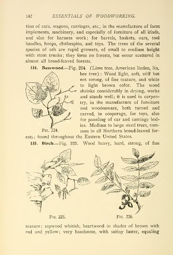
142 ESSENTIALS OF WOODWORKING.
tion of cars, wagons, carriages, etc., in the manufacture of farm
implements, machinery, and especially of furniture of all kinds,
and also for harness work; for barrels, baskets, oars, tool
handles, hoops, clothespins, and toys. The trees of the several
species of ash are rapid growers, of small to medium height
with stout trunks; they form no forests, but occur scattered in
almost all broad-leaved forests.
134. Basswood.—Fig. 224 (Lime tree, American linden, lin,
bee tree) : Wood light, soft, stiff but
not strong, of fine texture, and white
to light brown color. The woodshrinks considerably in drying, works
and stands well; it is used in carpen-
try, in the manufacture of furniture
and woodenware, both turned and
carved, in cooperage, for toys, also
for paneling of car and carriage bod-
ies. Medium to large sized trees, com-
mon in all Northern broad-leaved for-
ests; found throughout the Eastern United States.
135. Birch Fig. 225. Wood heavy, hard, strong, of fine
Fig. 224.
Fig. 225. Fig. 226.
texture; sapwood whitish, heartwood in shades of brown with
red and yellow; very handsome, with satiny luster, equaling
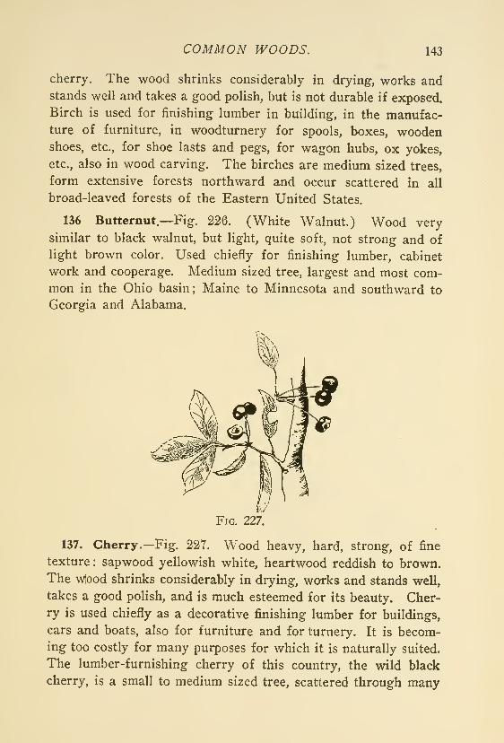
COMMON WOODS.'
143
cherry. The wood shrinks considerably in drying, works andstands well and takes a good polish, but is not durable if exposed.
Birch is used for finishing lumber in building, in the manufac-ture of furniture, in woodturnery for spools, boxes, woodenshoes, etc., for shoe lasts and pegs, for wagon hubs, ox yokes,
etc., also in wood carving. The birches are medium sized trees,
form extensive forests northward and occur scattered in all
broad-leaved forests of the Eastern United States.
136 Butternut.—Fig. 226. (White Walnut.) Wood very
similar to black walnut, but light, quite soft, not strong and of
light brown color. Used chiefly for finishing lumber, cabinet
work and cooperage. Medium sized tree, largest and most com-mon in the Ohio basin; Maine to Minnesota and southward to
Georgia and Alabama.
Fig. 227.
137. Cherry.—Fig. 227. Wood heavy, hard, strong, of fine
texture: sapwood yellowish white, heartwood reddish to brown.
The wtood shrinks considerably in drying, works and stands well,
takes a good polish, and is much esteemed for its beauty. Cher-ry is used chiefly as a decorative finishing lumber for buildings,
cars and boats, also for furniture and for turnery. It is becom-ing too costly for many purposes for which it is naturally suited.
The lumber-furnishing cherry of this country, the wild black
cherry, is a small to medium sized tree, scattered through many
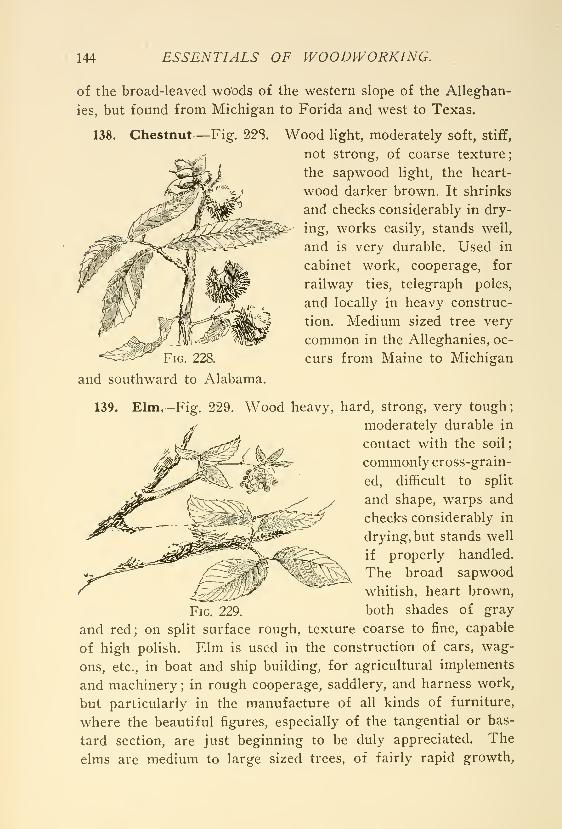
144 ESSENTIALS OF WOODWORKING.
of the broad-leaved woiods of the western slope of the Alleghan-
ies, but found from Michigan to Forida and west to Texas.
138. Chestnut—Fig. 22S. Wood light, moderately soft, stiff,
not strong, of coarse texture;
the sapwood light, the heart-
wood darker brown. It shrinks
and checks considerably in dry-
ing, works easily, stands well,
and is very durable. Used in
cabinet work, cooperage, for
railway ties, telegraph poles,
and locally in heavy construc-
tion. Medium sized tree very
common in the AUeghanies, oc-
FiG. 228. curs from Maine to Michigan
and southward to Alabama.
139. Elm,—Fig. 229. Wood heavy, hard, strong, very tough;
moderately durable in
contact with the soil
;
commonly cross-grain-
ed, difficult to split
and shape, warps and
checks considerably in
drying, but stands well
if properly handled.
The broad sapwood
whitish, heart brown.
Fig. 229. both shades of gray
and red; on split surface rough, texture coarse to fine, capable
of high polish. Elm is used in the construction of cars, wag-
ons, etc., in boat and ship building, for agricultural implements
and machinery ; in rough cooperage, saddlery, and harness work,
but particularly in the manufacture of all kinds of furniture,
where the beautiful figures, especially of the tangential or bas-
tard section, are just beginning to be duly appreciated. The
elms are medium to large sized trees, of fairly rapid growth,
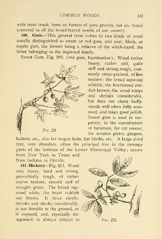
COMMON WOODS. 145
with stout trunk, form no forests of pure growth, but are foundscattered in all the broad-leaved woods of our country.
140. Gum.—This general term refers to two kinds of woodusually distinguished as sweet or red gum, and sour, black, ortupelo gum, the former being a relajtive of the witch-hazel, the
latter belonging to the dogwood family.
Sweet Gum. Fig. 230. (red gum, liquidambar); Wood rather
heavy, rather soft, quite
stifif and strong, tough, com-monly cross-grained, of fine
texture; the broad sapwoodwhitish, the heartwood red-
dish brown ; the wood warps
and shrinks considerably,
but does not check badly,
stands well when fully seas-
oned, and takes good polish.
Sweet gum is used in car-
pentry, in the manufacture
of furniture, for cut veneer,
for wooden plates, plaques,
baskets, etc., also for wagon hubs, hat blocks, etc. A large sized
tree, very abundant, often the principal tree in the swampyparts of the bottoms of the Lower Mississippi Valley; occurs
from New York to Texas and
from Indiana to Florida.
141. Hickory—Fig. 23 L. Woodvery heavy, hard and strong,
proverbially tough, of rather
coarse texture, smooth and of
straight grain. The broad sap-
wood white, the heart reddish
nut brown. It dries slowly,
shrinks and checks considerably,
is not durable in the ground, or
if exposed, and, especially the
sapwood, is always subject to
Fig. 23(
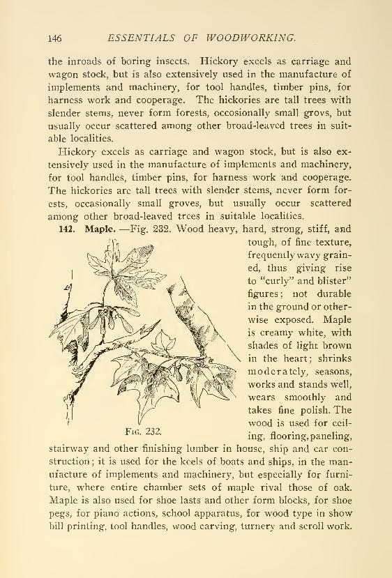
146 ESSENTIALS OF WOODWORKING.
the inroads of boring insects. Hickory excels as carriage and
wagon stock, but is also extensively used in the manufacture of
implements and machinery, for tool handles, timber pins, for
harness work and cooperage. The hickories are tall trees with
slender stems, never form forests, occosionally small grovs, but
usually occur scattered among other broad-leaved trees in suit-
able localities.
Hickory excels as carriage and wagon stock, but is also ex-
tensively used in the manufacture of implements and machinery,
for tool handles, timber pins, for harness work and cooperage.
The hickories are tall trees with slender stems, never form for-
ests, occasionally small groves, but usually occur scattered
among other broad-leaved trees in suitable localities.
142. Maple. —Fig. 232. Wood heavy, hard, strong, stiff, and
tough, of fine texture,
frequently wavy grain-
ed, thus giving rise
to "curly" and blister"
figures ; not durable
in the ground or other-
wise exposed. Maple
is creamy white, with
shades of light brown
in the heart; shrinks
moderately, seasons,
works and stands well,
wears smoothly and
takes fine polish. The
wood is used for ceil-
ing, flooring, paneling,
stairway and other finishing lumber in house, ship and car con-
struction ; it is used for the keels of boats and ships, in the man-
ufacture of implements and machinery, but especially for furni-
ture, where entire chamber sets of maple rival those of oak.
Maple is also used for shoe lasts and other form blocks, for shoe
pegs, for piano actions, school apparatus, for wood type in show
bill printing, tool handles, wood carving, turnery and scroll work.
Fig. 232.
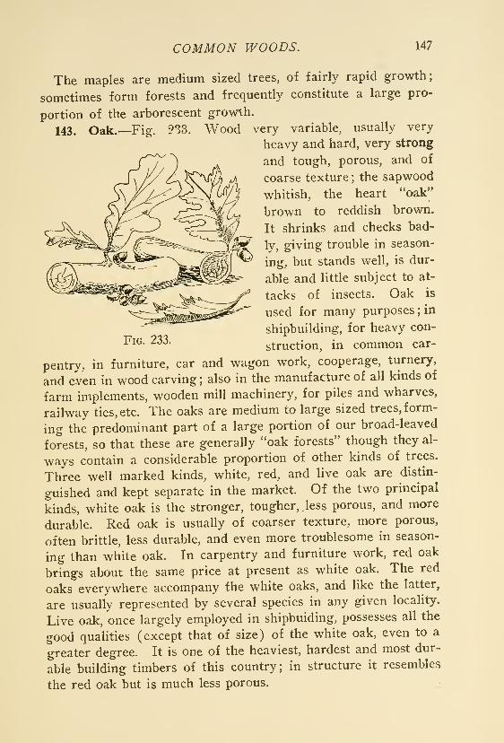
COMMON WOODS. 147
Fig. 233.
The maples are medium sized trees, of fairly rapid growth;
sometimes form forests and frequently constitute a large pro-
portion of the arborescent growth.
143. Oak.—Fig. ?33. Wood very variable, usually very
heavy and hard, very strong
and tough, porous, and of
coarse texture ; the sapwood
whitish, the heart "oak"
y^^—~-.^CAi brown to reddish brown.
^^^-By' It shrinks and checks bad-
j{.^' ly, giving trouble in season-
ing, but stands well, is dur-
able and little subject to at-
tacks of insects. Oak is
used for many purposes ; in
shipbuilding, for heavy con-
struction, in common car-
pentry, in furniture, car and wagon work, cooperage, turnery,
and even in wood carving ; also in the manufacture of all kinds of
farm implements, wooden mill machinery, for piles and wharves,
railway ties, etc. The oaks are medium to large sized trees, form-
ing the predominant part of a large portion of our broad-leaved
forests, so that these are generally "oak forests" though they al-
ways contain a considerable proportion of other kinds of trees.
Three well marked kinds, white, red, and live oak are distin-
guished and kept separate in the market. Of the two principal
kinds, white oak is the stronger, tougher,. less porous, and more
durable. Red oak is usually of coarser texture, more porous,
often brittle, less durable, and even more troublesome in season-
ing than white oak. In carpentry and furniture work, red oak
brings about the same price at present as white oak. The red
oaks everywhere accompany the white oaks, and like the latter,
are usually represented by several species in any given locality.
Live oak, once largely employed in shipbuiding, possesses all the
good qualities (except that of size) of the white oak, even to a
greater degree. It is one of the heaviest, hardest and most dur-
able building timbers of this country ; in structure it resembles
the red oak but is much less porous.
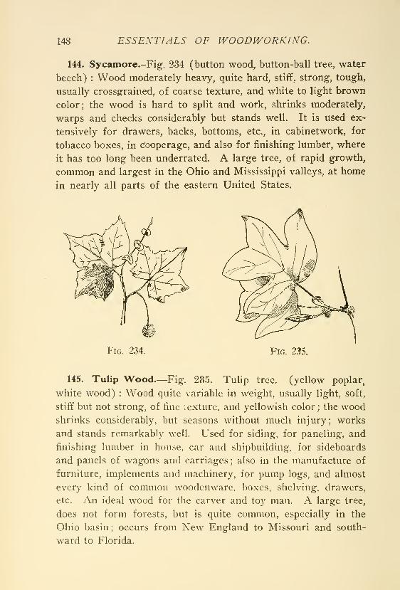
148 ESSENTIALS OF WOODWORKING.
144. Sycamore.-Fig. 234 (button wood, button-ball tree, water
beech) : Wood moderately heavy, quite hard, stiff, strong, tough,
usually crossgrained, of coarse texture, and white to light brown
color; the wood is hard to split and work, shrinks moderately,
warps and checks considerably but stands well. It is used ex-
tensively for drawers, backs, bottoms, etc., in cabinetwork, for
tobacco boxes, in Cooperage, and also for finishing lumber, where
it has too long been underrated. A large tree, of rapid growth,
common and largest in the Ohio and Mississippi valleys, at home
in nearly all parts of the eastern United States.
Fig. 234. Fig. 235.
145. Tulip Wood.—Fig. 285. Tulip tree, (yellow poplar,
white wood) : Wood quite variable in weight, usually light, soft,
stiff but not strong, of fine ;exture, and yellowish color ; the woodshrinks considerably, but seasons without much injury; works
and stands remarkably well. Used for siding, for paneling, and
finishing lumber in house, car and shipbuilding, for sideboards
and panels of wagons and carriages ; also in the manufacture of
furniture, implements and machinery, for pump logs, and almost
every kind of common woodenware, boxes, shelving, drawers,
etc. An ideal wood for the carver and to}^ man. A large tree,
does not form forests, but is quite common, especially in the
Ohio basin ; occurs from New England to Missouri and south-
ward to Florida.
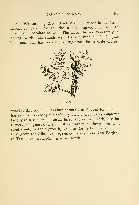
COMMON WOODS. 149
146. Walnut.-Fig. 23f^. Black Walnut. Wood heavy, hard,
strong, of coarse texture; the narrow sapwood whitish, the
heartwood chocolate brown. The wtood shrinks moderately in
drying, works and stands well, takes a good polish, is quite
handsome, and has been for a long time the favorite cabinet
Fig. 236.
wolod in this country. Walnut formerly used, even for fencing,
has become too costly for ordinary uses, and is to-day employed
largely as a veneer, for inside finish and cabinet work, also for
turnery, for gunstocks, etc. Black walnut is a large tree, with
stout trunk, of rapid growth, and was formerly quite abundant
throughout the Alleghany region, occurring from New England
to Texas, and from Michigan to Florida.
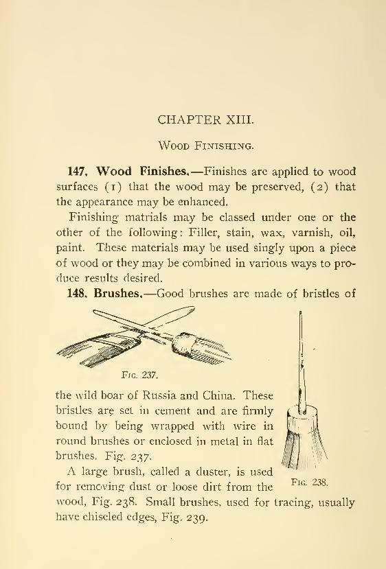
CHAPTER XIII.
Wood Finishing.
147, Wood Finishes.—Finishes are applied to woodsurfaces (i) that the wood may be preserved, (2) that
the appearance may be enhanced.
Finishing matrials may be classed under one or the
other of the following: Filler, stain, wax, varnish, oil,
paint. These materials may be used singly upon a piece
of wood or they may be combined in various ways to pro-
duce results desired.
148. Brushes,—Good brushes are made of bristles of
Fig. 237.
the wild boar of Russia and China. These
bristles are set in cement and are firmly
bound by being wrapped with wire in
round brushes or enclosed in metal in flat
brushes. Fi^. 237.
A large brush, called a duster, is used
for removing dust or loose dirt from the
wood. Fig. 238. Small brushes, used for tracing, usually
have chiseled edges, Fig. 239.
Fig. 238.
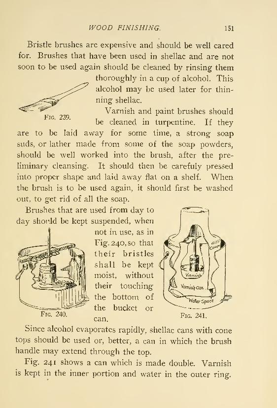
WOOD FINISHING. 151
Fig. 239.
Bristle brushes are expensive and should be well cared
for. Brushes that have been used in shellac and are not
soon to be used again should be cleaned by rinsing them
thoroughly in a cup of alcohol. This
alcohol may be used later for thin-
ning shellac.
Varnish and paint brushes should
be cleaned in turpentine. If they
are to be laid away for some time, a strong soap
suds, or lather made from some of the soap powders,
should be well worked into the brush, after the pre-
liminary cleansing. It should then be carefuly pressed
into proper shape and laid away flat on a shelf. Whenthe brush is to be used again, it should first be washed
out, to get rid of all the soap.
Brushes that are used from day to
day shonld be kept suspended, when
not in use, as in
Fig. 240, so that
their bristles
shall be kept
moist, without
their touching
the bottom of
the bucket or
can.
Since alcohol evaporates rapidly, shellac cans with cone
tops should be used or, better, a can in which the brush
handle may extend through the top.
Fig. 241 shows a can which is made double. Varnishis kept in the inner portion and water in the outer ring.
Fig. 240.
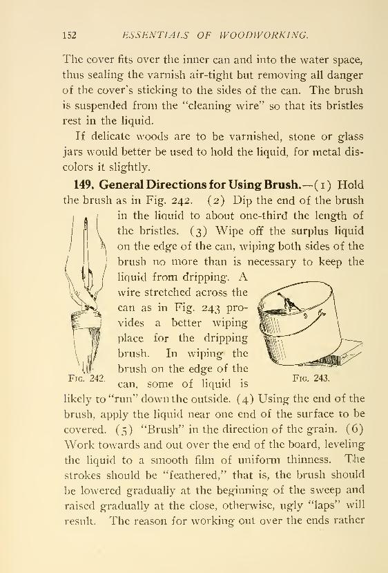
152 ESSENTIALS OF WOODWORKING.
The cover fits over the inner can and into the water space,
thus sealing the varnish air-tight but removing all danger
of the cover's sticking to the sides of the can. The brush
is suspended from the ''cleaning wire" so that its bristles
rest in the liquid.
If delicate woods are to be varnished, stone or glass
jars would better be used to hold the liquid, for metal dis-
colors it slightly.
149, General Directions for Using Brush.— ( i ) Hold
the brush as in Fig. 242. (2) Dip the end of the brush
in the liquid to about one-third the length of
the bristles. (3) Wipe off the surplus liquid
on the edge of the can, wiping both sides of the
brush no more than is necessary to keep the
liquid from dripping. Awire stretched across the
can as in Fig. 243 pro-
vides a better wiping
place for the dripping
brush. In wiping the
brush on the edge of the
can, some of liquid is
likely to ''run" down the outside. (4) Using the end of the
brush, apply the liquid near one end of the surface to be
covered. (5) "Brush" in the direction of the grain. (6)
Work towards and out over the end of the board, leveling
the liquid to a smooth film of uniform thinness. The
strokes should be "feathered," that is, the brush should
be lowered gradually at the beginning of the sweep and
raised gradually at the close, otherwise, ugly "laps" will
result. The reason for working out over the ends rather
Fig. 242. Fig. 243.
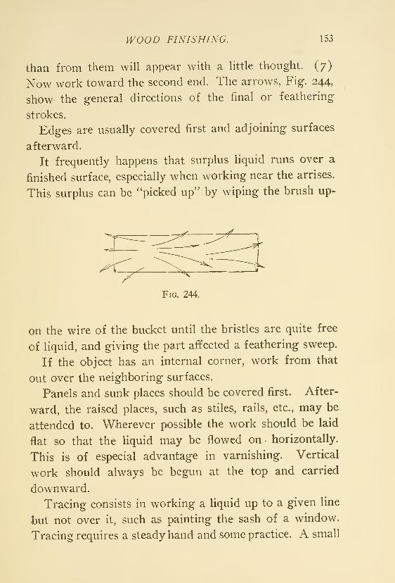
WOOD FINISHING. 153
than from them will appear with a little thought. (7)
Now work toward the second end. The arrows, Fig. 244,
show the general directions of the final or feathering
strokes.
Edges are usually covered first and adjoining surfaces
afterward.
It frequently happens that surplus liquid runs over a
finished surface, especially when working near the arrises.
This surplus can be ''picked up" by wiping the brush up-
FiG. 244.
on the wire of the bucket until the bristles are quite free
of liquid, and giving the part affected a feathering sweep.
If the object has an internal corner, work from that
out over the neighboring surfaces.
Panels and sunk places should be covered first. After-
ward, the raised places, such as stiles, rails, etc., may be
attended to. Wherever possible the work should be laid
flat so that the liquid may be flowed on • horizontally.
This is of especial advantage in varnishing. Vertical
work should always be begun at the top and carried
downward.
Tracing consists in working a liquid up to a given line
but not over it, such as painting the sash of a window.
Tracing requires a steady hand and some practice. A small
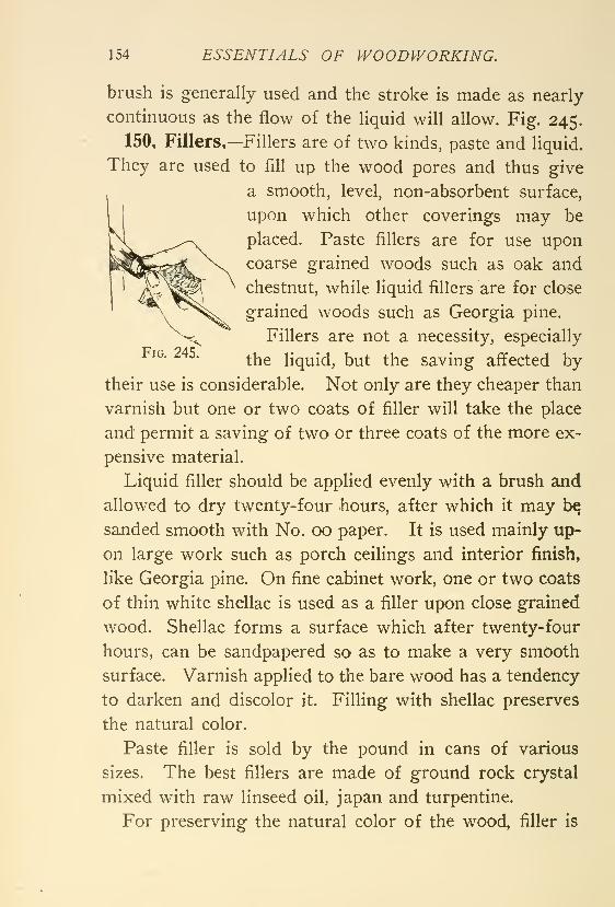
154 ESSENTIALS OF WOODWORKING.
brush is generally used and the stroke is made as nearly
continuous as the flow of the liquid will allow. Fig. 245.
150, Fillers,—Fillers are of two kinds, paste and liquid.
They are used to fill up the wood pores and thus give
a smooth, level, non-absorbent surface,
upon which other coverings may be
placed. Paste fillers are for use upon
coarse grained woods such as oak and
chestnut, while liquid fillers are for close
grained woods such as Georgia pine.
Fillers are not a necessity, especiallyiG. 45.
^j^^ liquid, but the saving affected by
their use is considerable. Not only are they cheaper than
varnish but one or two coats of filler will take the place
and permit a saving of two or three coats of the more ex-
pensive material.
Liquid filler should be applied evenly with a brush and
allowed to dry twenty-four hours, after which it may b^
sanded smooth with No. 00 paper. It is used mainly up-
on large work such as porch ceilings and interior finish,
like Georgia pine. On fine cabinet work, one or two coats
of thin white shellac is used as a filler upon close grained
wood. Shellac forms a surface which after twenty-four
hours, can be sandpapered so as to make a very smooth
surface. Varnish applied to the bare wood has a tendency
to darken and discolor it. Filling with shellac preserves
the natural color.
Paste filler is sold by the pound in cans of various
sizes. The best fillers are made of ground rock crystal
mixed with raw linseed oil, japan and turpentine.
For preserving the natural color of the wood, filler is
WOOD FINISHING. 155
left white; for Flemish, it is colored brown; for antique
and weathered finishes, it is dark. Fillers can be pur-
chased ready colored.
151, FUling with Paste Filler,— (i) Thin the filler
with turpentine until it makes a thin paste. (2) With a
stiff-bristled brush, force the filler into the pores of the
wood and leave the surface covered with a thin coating.
(3) Allow this to stand until the filler has ''flatted,"
that is, until the "gloss" has disappeared and the filler
becomes dull and chalkish. The time required for this
to take place varies. Twenty minutes is not unusual. (4)
Rub the filler off just as soon as it has flatted—do not let
it stand longer, for the longer it stands the harder it is to
remove. Rub across the grain as much as is possible,
using a wad of excelsior. Finish fine work by going
over it a second time with a cloth, rubbing with the grain
as well as across, that the "high lights" may be clear of
filler.
On fine work use a felt pad to rub the filler into the
pores, and rub off with a cloth only.
Twenty-four hours should be allowed the filler to hard-
en. One filling is sufficient for ordinary work; on fine
work the above process is sometimes repeated after the
first filling has hardened.
The striking contrasts in the grain of wood such as
oak and chestnut, obtained by the use of colored fillers,
are due to the dark filler's remaining in the open grain
but being wiped off of the close grain—the "high lights."
On quarter-sawed oak, each flake is sometimes sanded
with fine paper. No. 00, to remove the stain that the con-
trast may be sharper.
156 ESSENTIALS OF WOODWORKING.
Excelsior and rags used in cleaning off filler must not
be allowed to lie around but must be burned for they are
subject to spontaneous combustion and are dangerous.
152. Stains.—Stains are used to darken the high lights
of wood preparatory to the application of a relatively
darker filler. By varying the intensity of the stain
different results may be obtained with the same color of
filler. Stains are also used without fillers.
There are three kinds of stains: (i) water, (2) oil,
(3) spirit. Each kind has its advantag^es and its disad-
vantages.
Wood stains are cheap, penetrate the wood deeply, and
are transparent. They cause the grain of the wood to
''rough up," however, and for this reason are used mainly
upon hard woods which require darkening before the
application of a filler. The wood is sanded before the
filler is applied. Where water stain is not to be followed
by filler, it is customary to thoroughly moisten the sur-
face to be covered with water alone. After this has dried,
the surface is sanded with fine paper and the stain ap-
plied. The stain does not raise the grain as it otherwise
would.
Water stains may be applied with a brush or a sponge.
They are sometimes heated that they may enter the wood
more deeply. Any coloring matter that can be dissolved
in water will make a wood dye or stain.
Oil stains, like water stains, are often used to stain
wood before filling. They are more generally used where
no filling is desired. They are easier to apply evenly than
water or spirit stains. They do not raise the grain of
the wood like the other stains. On the other hand, they
WOOD FINISHING. 157
do not penetrate and therefore cannot color hard woods
dark. Neither do they give the clear effects.
Most oil stains are applied with a brush, after which
the surface of the wood is immediately wiped clean with
a cloth.
Spirit stains are but little used where surfaces of any
size are to be covered. They are expensive, fade easily,
and are hard to apply evenly.
They are applied with a brush and dry very quickly.
A stain which penetrates deeply and is clear is obtained
by placing the wood in a closed receptacle in which is
placed a dish of concentrated ammonia. The fumes of
this Hquid cause a chemical change to take place, giving
to the wood a rich nut-brown color.
153, Waxing,—An old finish that has recently become
popular is that of waxing. It takes the place of the var-
nish, by which it was supplanted years ago.
Wax finish is easily appHed and is cheaper than var-
nish. It will not stand wetting. However, it is easily re-
paired.
Our ancestors used to make wax polish by "cutting"
beeswax with turpentine.
Rapid drying and hardening waxes can be purchased
now-a-days. They require a smooth surface and a very
thin application for a successful result. Too much waxupon a rough surface will produce very ugly, white, chalk-
like spottings as the wax dries. These are especially
noticeable upon dark finishes. Waxes colored black over-
come this but are not needed if the ordinary wax is prop-
erly applied.
In finishing with wax the following directions may be
12
158 ESSENTIALS OF WOODWORKING.
followed: (i) Stain the wood, if a very dark finish is de-
sired. (2) If the wood is coarse-grained, put on two coats
of paste filler and rub it off carefully, that a smooth sur-
face may be prepared. Allow the stain twelve hours in
which to dry, also each coat of the filler. (3) With a soft
cloth apply as thin a coating of wax as can be and yet
cover the wood. Wax is in paste form. (4) Allow this to
stand five or ten minutes, then rub briskly with a soft dry
cloth to polish.( 5 ) After this coat has stood for twenty-
four hours another may be applied in the same manner.
A thin coat of shellac brushed evenly upon the hard-
ened filler ^'brings out" the grain and makes an excellent
base for wax as well as varnish. It should stand twenty-
four hours and then be sanded smooth with No. 00 sand-
paper before the wax is applied.
There are other patent preparations which give the
same soft effects as wax and are as easily applied—in
fact, some of them are but wax in liquid form.
154. Varnishes,—Varnishes are used where a hard
transparent coating is desired. There are two kinds, ( i
)
shellac or spirit varnish, (2) copal or oil varnish.
Varnishes vary greatly in quality and therefore in price.
If made of specially selected pale gum for use on light or
white woods the price will be higfher than for that of or-
dinary color tho the quality may be no higher.
Rubbing varnishes are so made that they may take a
"rubbed finish."
Varnishing should be done in a room in which the
temperature can be kept from 70 to 80 degrees Fahr., and
which is comparatively free from dust. The surface to
be covered must be clean, dry and filled even and smooth.
WOOD FINISHING. 159
155, Shellac,—Shellac or spirit varnish is a solution of
lac and alcohol. Lac is soluble in both grain and woodalcohol but grain alcohol is preferable. Beds of crude lac
are found in parts of Africa and South America where
the lac has been left by the decay of leaves and twigs
which it at one time encrusted. Crude lac is deposited up-
on leaves and twigs of certain of the lac-bearing trees by
countless numbers of insects which draw out the sap.
Stick-lac is crude lac which has been purified somewhat
of the bodies and eggs of the insects and rolled into stick
forms. When crushed and washed it is known as seed-
lac. When fully purified, which is done by melting and
straining, it is spread out and is known as shellac.
White shellac is obtained by bleaching. Orange shellac
is unbleached. Pure white shellac is used where the more
yellow shellac would discolor. Orange shellac is stronger
than white and will last longer but is harder to apply be-
cause it sets more rapidly.
Shellac varnish sets quickly, dries hard but softens un-
der moisture. Unlike oil varnish, it does not "level up'*
and must, therefore, be brushed on quickly, using long,
even strokes. No spots must be omitted for they cannot
be "touched up."
156, Shellac Finishes.—The use of one or more coats
of shellac preparatory to a varnish finish has been noted.
A very simple finish, and one that is easily applied, is
obtained by covering stained wood with a very thin coat
of shellac.
To obtain the finish known as egg-shell gloss, ( i ) Coat
the smooth wood with from three to six applications of
thin shellac. Allow each coat twenty-four hours in which
160 ESSENTIALS OF WOODWORKING.
to harden. (2) Rub to a smooth surface each hardened
coat using curled hair or fine steel wool or fine oiled sand-
paper.
157, Oil or Copal Varnishes,—Oil varnish is com-
posed of copal gum, boiled oil and turpentine. Copal
gums are obtained from Africa mainly, in certain parts
of which they are found as fossil resins, the remains of
forests which once covered the ground.
Pressed flaxseed furnish crude linseed oil while the
long leaf pine of the South, furnishes the turpentine pitch.
The oil is prepared for use by boiling it in huge kettles
with different materials which cause it to change chemi-
cally. It is then put away to settle and age, that is to clear
and purify itself. It takes from one to six months for the
oil to reach a proper degree of clearness and purity. Tur-
pentine is obtained from its pitch by distillation.
The copal gums are melted and boiled thoroly with
the oil. Turpentine is added after the mixture of gumand oil has cooled sufficiently. The whole is then strained
several times, placed in tanks to age or ripen. From
one month to a year, or even more, is required.
The quality of varnish depends upon the qualities of
the gums, the proportion of oil and turpentine and the
care which is exercised in the boiling process.
158, Flowing Copal Varnish.— (i) Lay on the var-
nish quickly in a good heavy coat. Use a good varnish
brush and dip the bristles deeply into the liquid, wiping
them off just enough to prevent dripping. (2) Wipe the
bristles quite free of varnish;go over the surface and
pick up as much of the surplus liquid as the brush will
hold. Replace the varnish in the can by wiping the
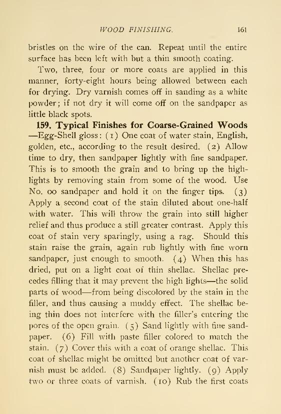
WOOD FINISHING. 161
bristles on the wire of the can. Repeat until the entire
surface has been left with but a thin smooth coating.
Two, three, four or more coats are applied in this
manner, forty-eight hours being allowed between each
for drying. Dry varnish comes off in sanding as a white
powder; if not dry it will come off on the sandpaper as
little black spots.
159, Typical Finishes for Coarse-Grained Woods—Egg-Shell gloss : ( I ) One coat of water stain, English,
golden, etc., according to the result desired. (2) Allow
time to dry, then sandpaper lightly with fine sandpaper.
This is to smooth the grain and to bring up the high-
lights by removing stain from some of the wood. Use
No. 00 sandpaper and hold it on the finger tips. (3)
Apply a second coat of the stain diluted about one-half
with water. This will throw the grain into still higher
relief and thus produce a still greater contrast. Apply this
coat of stain very sparingly, using a rag. Should this
stain raise the grain, again rub lightly with fine worn
sandpaper, just enough to smooth. (4) When this has
dried, put on a light coat of thin shellac. Shellac pre-
cedes filling that it may prevent the high lights—the solid
parts of wood—from being discolored by the stain in the
filler, and thus causing a muddy effect. The shellac be-
ing thin does not interfere with the filler's entering the
pores of the open grain.( 5 ) Sand lightly with fine sand-
paper. (6) Fill with paste filler colored to match the
stain. (7) Cover this with a coat of orange shellac. This
coat of shellac might be omitted but another coat of var-
nish must be added. (8) Sandpaper lightly. (9) Apply
two or three coats of varnish. ( 10) Rub the first coats
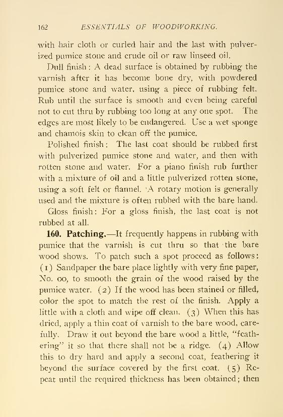
162 ESSENTIALS OF WOODWORKING.
with hair cloth or curled hair and the last with pulver-
ized pumice stone and crude oil or raw linseed oil.
Dull finish : A dead surface is obtained by rubbing the
varnish after it has become bone dry, with powdered
pumice stone and water, using a piece of rubbing felt.
Rub until the surface is smooth and even being careful
not to cut thru by rubbing too long at any one spot. The
edges are most likely to be endangered. Use a wet sponge
and chamois skin to clean off the pumice.
Polished finish : The last coat should be rubbed first
with pulverized pumice stone and water, and then with
rotten stone and water. For a piano finish rub further
with a mixture of oil and a little pulverized rotten stone,
using a soft felt or flannel. A rotary motion is generally
used and the mixture is often rubbed with the bare hand.
Gloss finish : For a gloss finish, the last coat is not
rubbed at all.
160. Patching,—It frequently happens in rubbing with
pumice that the varnish is cut thru so that the bare
wood shows. To patch such a spot proceed as follows:
( I ) Sandpaper the bare place lightly with very fine paper,
No. oo, to smooth the grain of the wood raised by the
pumice water. (2) If the wood has been stained or filled,
color the spot to match the rest of the finish. Apply a
little with a cloth and wipe off clean. (3) When this has
dried, apply a thin coat of varnish to the bare wood, care-
fully. Draw it out beyond the bare wood a little, ''feath-
ering" it so that there shall not be a ridge. (4) Allow
this to dry hard and apply a second coat, feathering it
beyond the surface covered by the first coat. (5) Re-
peat until the required thickness has been obtained; then
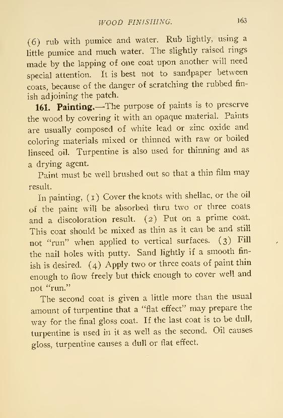
WOOD FINISHING. 163
(6) rub with pumice and water. Rub lightly, using a
little pumice and much water. The slightly raised rings
made by the lapping of one coat upon another will need
special attention. It is best not to sandpaper between
coats, because of the danger of scratching the rubbed fin-
ish adjoining the patch.
161. Painting,—The purpose of paints is to preserve
the wood by covering it with an opaque material. Paints
are usually composed of white lead or zinc oxide and
coloring materials mixed or thinned with raw or boiled
linseed oil. Turpentine is also used for thinning and as
a drying agent.
Paint must be well brushed out so that a thin film may
result.
In painting, ( I ) Cover the knots with shellac, or the oil
of the paint will be absorbed thru two or three coats
and a discoloration result. (2) Put on a prime coat.
This coat should be mixed as thin as it can be and still
not "run" when applied to vertical surfaces. (3) Fill
the nail holes with putty. Sand lightly if a smooth fin-
ish is desired. (4) Apply two or three coats of paint thin
enough to flow freely but thick enough to cover well and
not "run."
The second coat is given a little more than the usual
amount of turpentine that a "flat effect" may prepare the
way for the final gloss coat. If the last coat is to be dull,
turpentine is used in it as well as the second. Oil causes
gloss, turpentine causes a dull or flat effect.
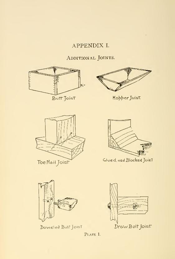
APPENDIX I.
Additional Joints.
E,viTr JoinT MoJ^fDerJoiQt
ToeH6^\iJo\aTCivjed. aad Blocked Joi'fzT
I)owelecl BuTT JoiqT DrcywBoltJoiner
Plate 1.
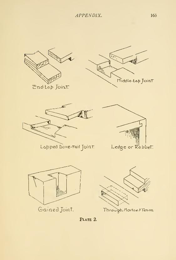
APPENDIX. 165
'ricWd^p Join.17
Lesppecl hoMZ-TQW Joint: Ledqe or "R'abDeT
Gained Joii?.t. Tb ro >ob>b- -^ orti 5 e /. Ten otT.
Plate 2.
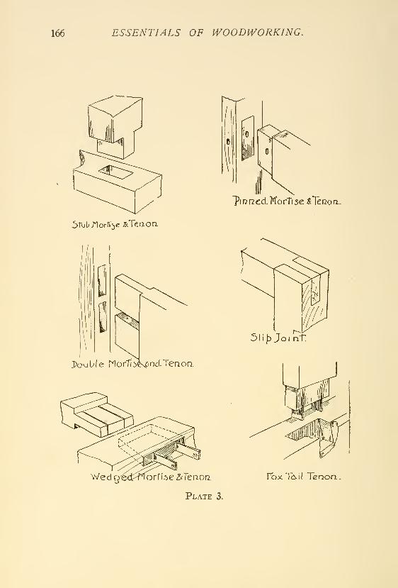
166 ESSENTIALS OF WOODWORKING.
bt\s\j AorTv^e ^'Vcn.OVL
I)ouL'le MorTi3espod lenon
T'mRcd.KorT/se &Tcuon..
Wed o€ct^orri:>e Zkleiiorz
Plate 3.
5 1 i |d Jo I n
ft)x T6.i( Tenon.
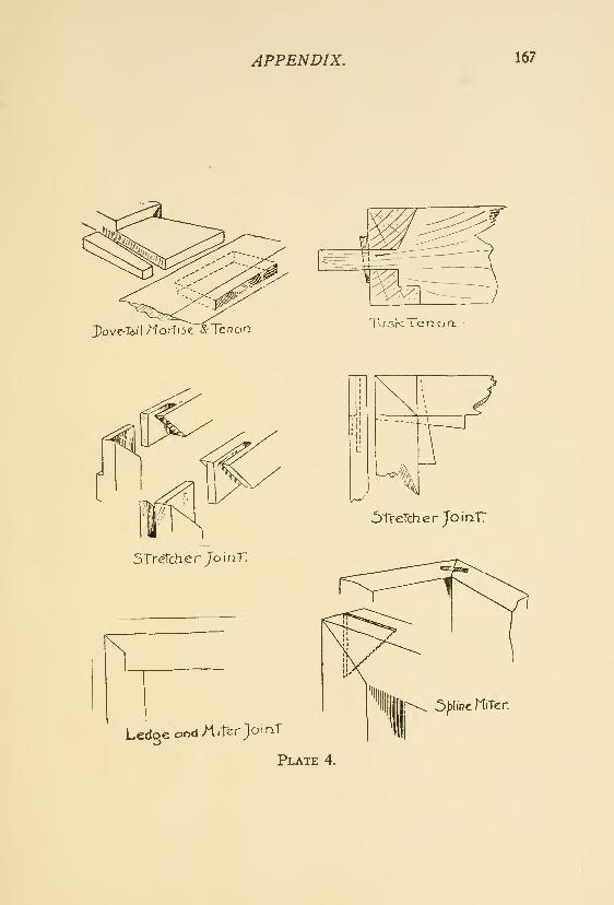
APPENDIX. 167
J)ov€-Td.iiMorhbc ScTenon Tuok Ten on.
Stretchier Jo iqT:
Ledpe and M.ter Joint
>4
Stretch e r Jo I nT?
^pUncnrcr.
Plate 4.
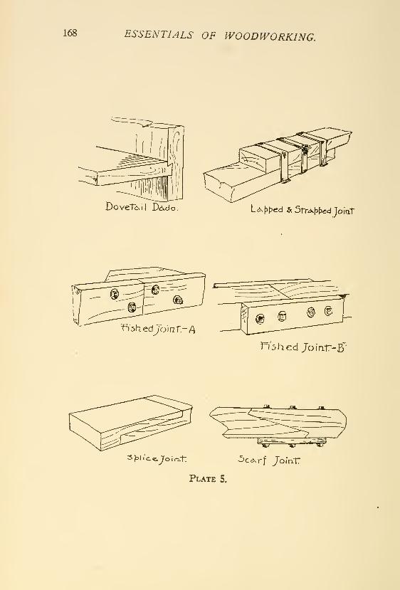
168 ESSENTIALS OF WOODWORKING.
DoveT(^il Dcixdo. Ld^f>f)ed * 5trd^\>\>c<i JoiaT
T\3he(iJo'\aT-f\
ri3hed /oinr-B*
Plate 5.
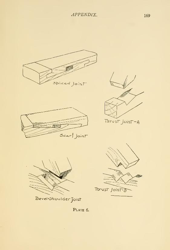
APPENDIX. 169
'Scesrf join.r"
Thrusrjoinr-A
Bevel -N3hcj I d e r Joi qT
Plate 6.
TDrvjsT joint
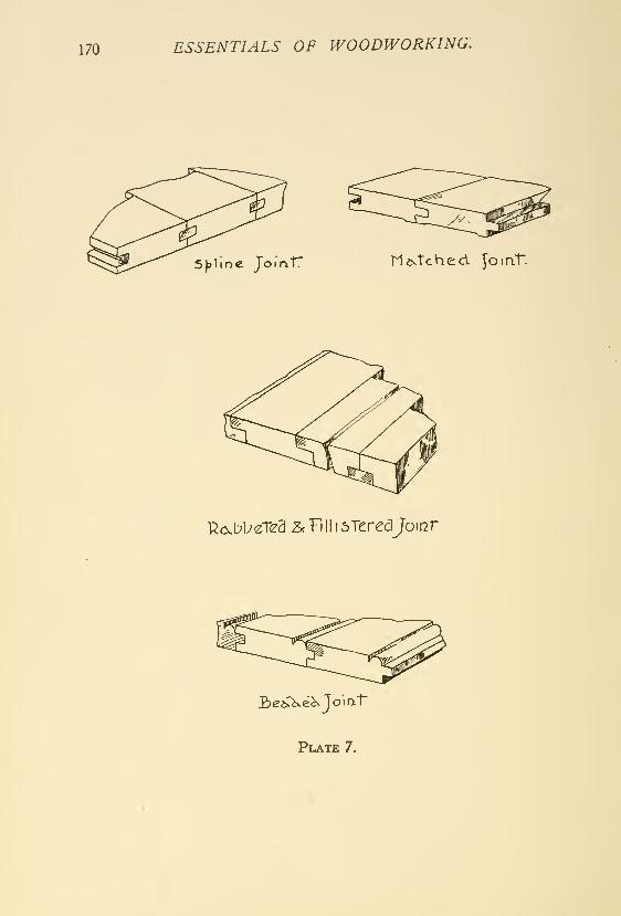
170 ESSENTIALS OF WOODWORKING.
5p\ine. Jo I at* Mistched yoinT.
Rcxbl72T(?a Zc Fi II 1 5rereclJoii7r
APPENDIX 11.
Wood Finishing Recipes.
1, Wax,—Cut up beeswax and add to it about one-
third of its volume of turpentine. Heat to the boihng
point in a double boiler. Or, melt a quantity of beeswax
and to this add an equal quantity of turpentine. Care
must be taken that the turpentine shall not catch fire.
2, Water Stains,—Any coloring matter that is soluble
in water will make a stain.
Mahogany : Three quarts of boiling water, one ounce
of Bismarck-brown aniline.
Brown : Extract of logwood, the size of a walnut, dis-
solved by boiling in four ounces of water. Apply hot and
repeat until the desired color is obtained.
Black : First stain the wood brown with the logwood
solution. Coat this with a stain prepared as follows:
Soak a teaspoonful of cast iron filings in four ounces of
acetic acid or vinegar. Allow it to stand for a week,
stirring it occasionally.
Walnut : Make a strong solution of powdered bicrom-
ate of potash and hot water. Over this stain, apply a coat
of the logwood stain.
3, Oil Stains,—Coach colors ground in Japan when
thinned with turpentine make good stain. Mix in the
proportion of one-half gallon of turpentine to one pound
of color and add a little boiled oil. Colors commonly
172 ESSENTIALS OF WOODWORKING.
used are drop black, Vandyke brown, medium chrome
yellow, burnt and raw umber and burnt and raw sienna.
Green : Drop-black, two parts, medium chrome yellow,
one part, a little red to kill the brightness.
Walnut: Asphaltum with a little Venetian red.
Golden oak: Asphaltum and turpentine thinned like
water, to be followed with filler darkened with burnt um-
ber and black.
Antique oak : Raw sienna properly thinned, with a little
burnt umber and black added.
I [4, Spirit Stains,
Black : Alcohol and aniline black.
Mahogany : Alcohol and Bismark brown.
Aniline stains cut with alcohol, and mixed with white
shellac and banana oil or amyl alcohol in equal parts make
good stains for small pieces of work.
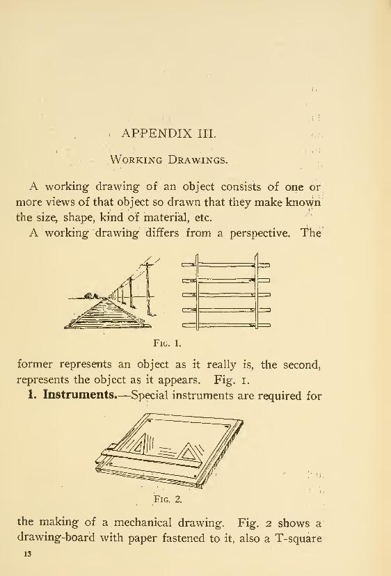
APPENDIX III.
Working Drawings. .
A working drawing of an object consists of one or
more views of that object so drawn that they make known'
the size, shape, kind of material, etc.
A working drawing differs from a perspective. The
Fig. 1.
former represents an object as it really is, the second,
represents the object as it appears. Fig. i.
1. Instruments.—Special instruments are required for
Fig. 2.
the making of a mechanical drawing. Fig. 2 shows a
drawing-board with paper fastened to it, also a T-square
13
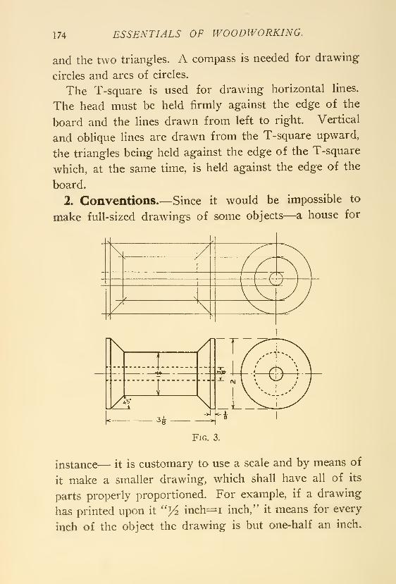
174 ESSENTIALS OF WOODWORKING.
and the two triangles. A compass is needed for drawing
circles and arcs of circles.
The T-square is used for drawing horizontal lines.
The head must be held firmly against the edge of the
board and the lines drawn from left to right. Vertical
and oblique lines are drawn from the T-square upward,
the triangles being held against the edge of the T-square
which, at the same time, is held against the edge of the
board.
2. Conventions.—Since it would be impossible to
make full-sized drawings of some objects—a house for
Fig. 3.
instance— it is customary to use a scale and by means of
it make a smaller drawing, which shall have all of its
parts properly proportioned. For example, if a drawing
has printed upon it ">^ inch=i inch," it means for every
inch of the object the drawing is but one-half an inch.
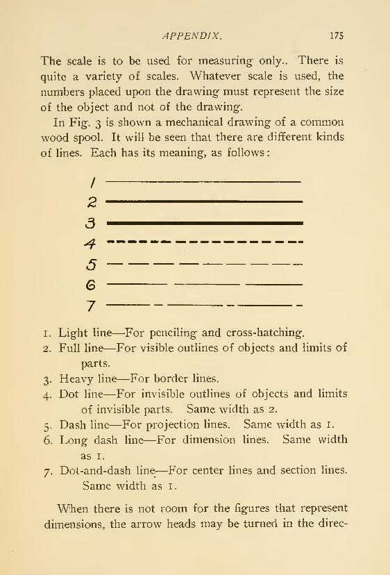
APPENDIX. 175
The scale is to be used for measuring only.. There is
quite a variety of scales. Whatever scale is used, the
numbers placed upon the drawing must represent the size
of the object and not of the drawing.
In Fig. 3 is shown a mechanical drawing of a common
wood spool. It will be seen that there are different kinds
of lines. Each has its meaning, as follows
:
/
2
3456
7
1. Light line—For penciling and cross-hatching.
2. Full line—For visible outlines of objects and limits of
parts.
3. Heavy line—For border lines.
4. Dot line—For invisible outlines of objects and limits
of invisible parts. Same width as 2.
5. Dash line—For projection lines. Same width as i.
6. Long dash line—For dimension lines. Same width
as I.
7. Dot-and-dash line—For center lines and section lines.
Same width as i.
When there is not room for the figures that represent
dimensions, the arrow heads may be turned in the direc-
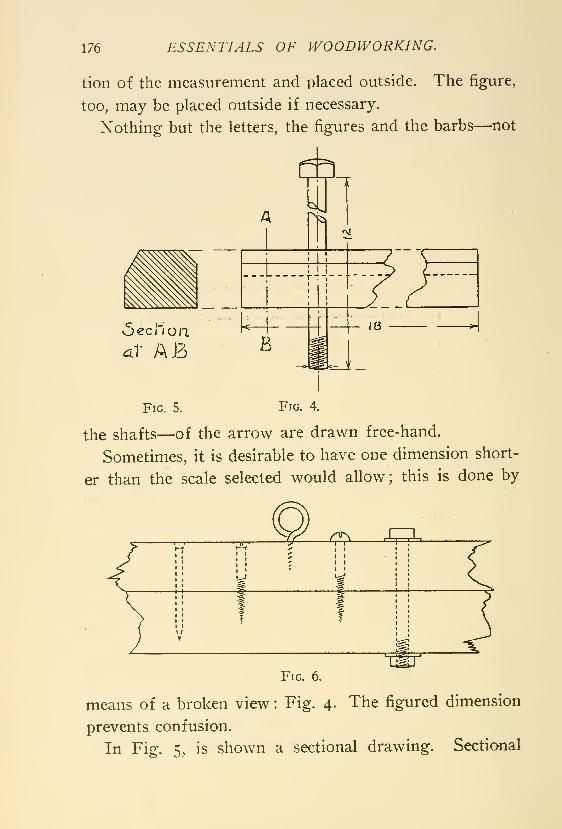
176 ESSENTIALS OF WOODWORKING.
tion of the measurement and placed outside. The figure,
too, may be placed outside if necessary.
Nothing but the letters, the figures and the barbs—not
oeci ion.
Fig. 5. Fig. 4.
the shafts—of the arrow are drawn free-hand.
Sometimes, it is desirable to have one dimension short-
er than the scale selected would allow; this is done by
ax
^=?r-
FiG. 6.
"^
means of a broken view : Fig. 4. The figured dimension
prevents confusion.
In Fig. 5, is shown a sectional drawing. Sectional
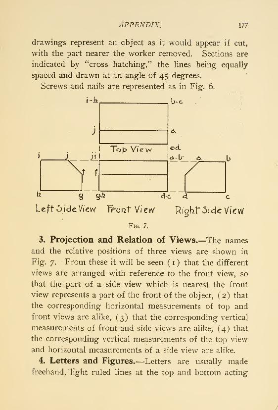
APPENDIX. \77
drawings represent an object as it would appear if cut,
with the part nearer the worker removed. Sections are
indicated by "cross hatching," the lines being equally
spaced and drawn at an angle of 45 degrees.
Screws and nails are represented as in Fig. 6.
A li
f f
TojD ViewA-b-
^2 9 S-/2 4c a:
Leftside View Tf-oiit View^ RighLtoi^e VicW
Fig. 7.
3. Projection and Relation of Views.—The names
and the relative positions of three views are shown in
Fig. 7. From these it will be seen ( i ) that the different
views are arranged with reference to the front view, so
that the part of a side view which is nearest the front
view represents a part of the front of the object, (2) that
the corresponding horizontal measurements of top and
front views are alike,( 3 ) that the corresponding vertical
measurements of front and side views are alike, (4) that
the corresponding vertical measurements of the top view
and horizontal measurements of a side view are alike.
4. Letters and Figures.—Letters are usually madefreehand, light ruled lines at the top and bottom acting
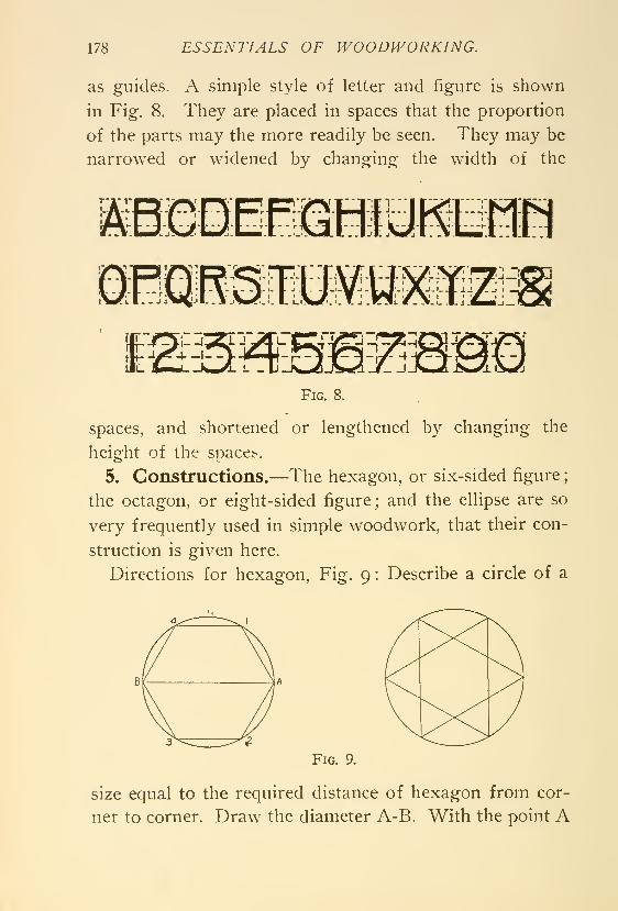
178 ESSENTIALS OF WOODWORKING.
as guides. A simple style of letter and figure is shown
in Fig. 8. They are placed in spaces that the proportion
of the parts may the more readily be seen. They may be
narrowed or widened by changing the width of the
Fig. 8.
spaces, and shortened or lengthened by changing the
height of the space^.
5. Constructions.—The hexagon, or six-sided figure
;
the octagon, or eight-sided figure; and the ellipse are so
very frequently used in simple woodwork, that their con-
struction is given here.
Directions for hexagon. Fig. 9: Describe a circle of a
Fig. 9.
size equal to the required distance of hexagon from cor-
ner to corner. Draw the diameter A-B. With the point A
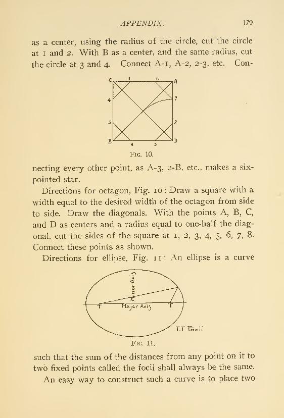
APPENDIX. 179
as a center, vising the radius of the circle, cut the circle
at I and 2. With B as a center, and the same radius, cut
the circle at 3 and 4. Connect A-i, A-2, 2-3, etc. Con-
FiG. 10.
necting every other point, as A-3, 2-B, etc., makes a six-
pointed star.
Directions for octagon, Fig. 10: Draw a square with a
width equal to the desired width of the octagon from side
to side. Draw the diagonals. With the points A, B, C,
and D as centers and a radius equal to one-half the diag-
onal, cut the sides of the square at i, 2, 3, 4, 5, 6, 7, 8.
Connect these points as shown.
Directions for ellipse. Fig. 11: An ellipse is a curve
T.T T^.
Fig. 11.
such that the sum of the distances from any point on it to
two fixed points called the focii shall always be the same.
An easy way to construct such a curve is to place two
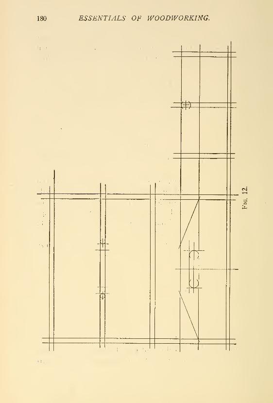
180 ESSENTIALS OF WOODWORKING.
4-
-M
"^""
d
f
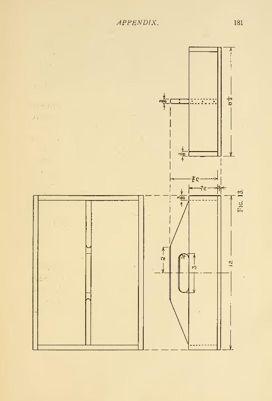
APPENDIX. 181
»|09 C 00
r)IO
*c- J
ra'
-fe-
/f^
V^J
182 ESSENTIALS OF WOODWORKING.
thumb tacks at the focii, attach the ends of a string to
them. With a pencil moving freely in the string but hold-
ing it taut draw the curve. By moving the tacks farther
apart or closer together and by lengthening or shortening-
the string, the size and shape of the curve may be changed
as desired.
6. Order of Procedure.—Beginners should strive to
know and to acquire good practice in drawing. Before
beginning see that the pencil is properly sharpened.
( 1 ) Determine the size and spacings of the views so
that the parts of the drawings may be properly placed.
(2) With light full lines block out the different views.
Blocking-out lines are made of indefinite length and the
proper distances marked off on them after they are
drawn. Holding the rule or scale upon the drawing ver-
tically, mark off the vertical spaces. Draw light lines
thru these points. Upon one of these horizontal lines
lay off the horizontal spaces. Draw light vertical lines
thru these points. Fig. 12.
(3) Put on the dimensions.
(4) Put on the lettering.
(5) The drawing is ready for inking. In blocking-
out, all lines are made full, light. In inking, the different
kinds must be represented properly. Fig. 13. If it is not
to be inked go over the lines that represent edges with the
pencil a second time so that the outlines of the object will
''stand out."
Books on the Manual Arts
Beginning Woodwork. At Home and in School. By
CLINTON SHELDON VAN DEUSEN ; illustrated by
Edwin Victor Lawrence.
A full and clear description in detail of the fundamental processes of elementary
benchwork in wood. This description is given through directions for making a few
simple, useful articles suitable either for school or home problems. Even without a
teacher a bright boy, by following this book faithfully, may acquire considerable skill.
It is a safe guide for farmers' boys as well as for city boys, and is especially well suited
for use in rural and village schools in which the teacher has had but little experience
in the use of woodworking tools. The book is illustrated by more than one hundred
figures, including ten plates of working drawings. Each of these figures is an orig-
inal drawing made expressly for this book. Price, $1.00.
Problems in Woodworking, By m. w. Murray.
A convenient collection of good problems ready to place in the hands of the pupils.
It consists of forty plates bound in heavy paper covers with brass fasteners. Each
plate is a working drawing, or problem in bench work that has been successfully
worked out by boys in one of the grades from seven to nine inclusive. Many of the
problems can be worked out in various ways according to the individual ability, inter-
est and taste of the pupil. Price, 75 cents. Board covers, 20 cents extra.
Problems in Furniture Making. By fred d. craw-SHAW.
This book consists of 32 plates of working drawings suitable for use in grammar and
high schools and 24 pages of text, including chapters on design, construction and fin-
ishes, and notes on the problems. Price, in heavy paper covers, $1.00. Board covers,
20 cents extra.
Problems in Mechanical Drawing. By charles a.
BENNETT. With drawings made by Fred D. Crawshaw.
This book consists of 80 plates and a few explanatory notes, and is bound in heavy
paper covers with brass fasteners. Its purpose is to furnish teachers of classes be-
ginning mechanical drawing with a large number of simple, practical problems. These
have been selected with reference to the formation of good habits in technique, the in-
terest of the pupils, and the subjects usually included in a grammar and first-year high
school course. The book covers simple projection—straight lines and circles, prob-
lems involving tangents, planes of projection, revolution of solids, developments, in-
tersections, isometric projection, lettering and working drawings. Each problem
given is unsolved and therefore in proper form to hand to the pupil for solution.
Price, $1.00. Board covers, 20 cents extra.
Books on the Manual Arts
Classroom Practice in Design. By james partonHANEY.
A concise, up-to-date, richly illustrated booklet on the teaching of applied design.
Very suggestive. Price, 50 cents.
The Wash Method of Handling Water Colour. ByFRANK FORREST FREDERICK.
"This little book is a helpful guide and affords a stimulus to the use of water-color
as practiced by the earlier painters, whose beautiful work is unexcelled." Price, 50
cents.
Manual Training Magazine.
An illustrated, bi-monthly publication devoted to the interests of the Manual Arts in
Education. Subscription price, $1.50 a year; single copies, 35 cents. In foreign
countries, including Canada, $1.75 a year ; single copies, 40 cents.
The Manual Arts PressPeoria, Illinois

Muv 12 idoa