the 4x4x4 led cube (arduino) - instructables.com
TRANSCRIPT
http://www.instructables.com/id/The-4x4x4-LED-cube-Arduino/
Home Sign Up! Browse Community Submit
All Art Craft Food Games Green Home Kids Life Music Offbeat Outdoors Pets Photo Ride Science Tech
The 4x4x4 LED cube (Arduino)by forte1994 on September 2, 2010
Table of Contents
The 4x4x4 LED cube (Arduino) . . . . . . . . . . . . . . . . . . . . . . . . . . . . . . . . . . . . . . . . . . . . . . . . . . . . . . . . . . . . . . . . . . . . . . . . . . . . . . . . . . . . . . . . . . . . . . . . . . . 1
Intro: The 4x4x4 LED cube (Arduino) . . . . . . . . . . . . . . . . . . . . . . . . . . . . . . . . . . . . . . . . . . . . . . . . . . . . . . . . . . . . . . . . . . . . . . . . . . . . . . . . . . . . . . . . . . . . 2
Step 1: Get the materials . . . . . . . . . . . . . . . . . . . . . . . . . . . . . . . . . . . . . . . . . . . . . . . . . . . . . . . . . . . . . . . . . . . . . . . . . . . . . . . . . . . . . . . . . . . . . . . . . . . . . 2
Step 2: Assemble the board(the LED cube base) . . . . . . . . . . . . . . . . . . . . . . . . . . . . . . . . . . . . . . . . . . . . . . . . . . . . . . . . . . . . . . . . . . . . . . . . . . . . . . . . . . . 3
Step 3: Defuse the LED . . . . . . . . . . . . . . . . . . . . . . . . . . . . . . . . . . . . . . . . . . . . . . . . . . . . . . . . . . . . . . . . . . . . . . . . . . . . . . . . . . . . . . . . . . . . . . . . . . . . . . 4
Step 4: Construct the cube . . . . . . . . . . . . . . . . . . . . . . . . . . . . . . . . . . . . . . . . . . . . . . . . . . . . . . . . . . . . . . . . . . . . . . . . . . . . . . . . . . . . . . . . . . . . . . . . . . . 5
Step 5: PROGRAM . . . . . . . . . . . . . . . . . . . . . . . . . . . . . . . . . . . . . . . . . . . . . . . . . . . . . . . . . . . . . . . . . . . . . . . . . . . . . . . . . . . . . . . . . . . . . . . . . . . . . . . . . 8
File Downloads . . . . . . . . . . . . . . . . . . . . . . . . . . . . . . . . . . . . . . . . . . . . . . . . . . . . . . . . . . . . . . . . . . . . . . . . . . . . . . . . . . . . . . . . . . . . . . . . . . . . . . . . . . . 9
Step 6: ADD on . . . . . . . . . . . . . . . . . . . . . . . . . . . . . . . . . . . . . . . . . . . . . . . . . . . . . . . . . . . . . . . . . . . . . . . . . . . . . . . . . . . . . . . . . . . . . . . . . . . . . . . . . . . . 9
Related Instructables . . . . . . . . . . . . . . . . . . . . . . . . . . . . . . . . . . . . . . . . . . . . . . . . . . . . . . . . . . . . . . . . . . . . . . . . . . . . . . . . . . . . . . . . . . . . . . . . . . . . . . . . 9
Comments . . . . . . . . . . . . . . . . . . . . . . . . . . . . . . . . . . . . . . . . . . . . . . . . . . . . . . . . . . . . . . . . . . . . . . . . . . . . . . . . . . . . . . . . . . . . . . . . . . . . . . . . . . . . . . . . 10
http://www.instructables.com/id/The-4x4x4-LED-cube-Arduino/
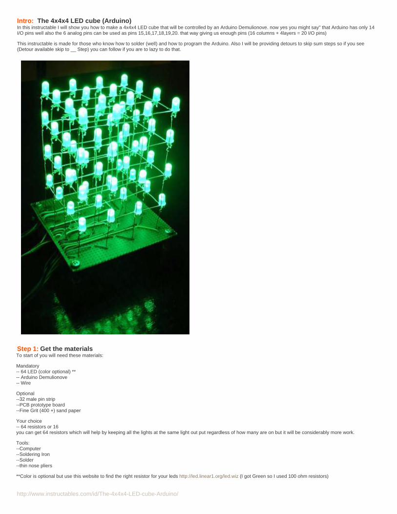
Intro: The 4x4x4 LED cube (Arduino)In this instructable I will show you how to make a 4x4x4 LED cube that will be controlled by an Arduino Demulionove. now yes you might say" that Arduino has only 14I/O pins well also the 6 analog pins can be used as pins 15,16,17,18,19,20. that way giving us enough pins (16 columns + 4layers = 20 I/O pins)
This instructable is made for those who know how to solder (well) and how to program the Arduino. Also I will be providing detours to skip sum steps so if you see(Detour available skip to __ Step) you can follow if you are to lazy to do that.
Step 1: Get the materialsTo start of you will need these materials:
Mandatory-- 64 LED (color optional) **-- Arduino Demulionove-- Wire
Optional--32 male pin strip--PCB prototype board--Fine Grit (400 +) sand paper
Your choice-- 64 resistors or 16you can get 64 resistors which will help by keeping all the lights at the same light out put regardless of how many are on but it will be considerably more work.
Tools:--Computer--Soldering Iron--Solder--thin nose pliers
**Color is optional but use this website to find the right resistor for your leds http://led.linear1.org/led.wiz (I got Green so I used 100 ohm resistors)
http://www.instructables.com/id/The-4x4x4-LED-cube-Arduino/
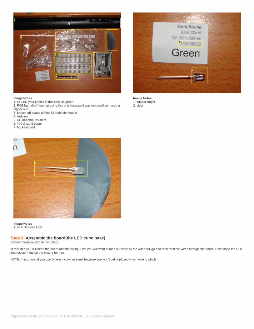
Image Notes1. 64 LED your choice in this case its green2. PCB but I didn't end up using this one because it was too small so I used abigger one3. broken off peace off the 32 male pin header4. Arduino5. 64-100 ohm resistors6. 400 G sand paper7. My keyboard
Image Notes1. supper Bright2. clear
Image Notes1. now Defused LED
Step 2: Assemble the board(the LED cube base)(Detour available skip to next step)
In this step you will need the board and the wiring. First you will want to map out were all the wires will go and then feed the wires through the board. Don't mind the LEDand resistor note on the picture for now.
NOTE: I recommend you use Different color wire just because you won't get confused which wire is which.
http://www.instructables.com/id/The-4x4x4-LED-cube-Arduino/
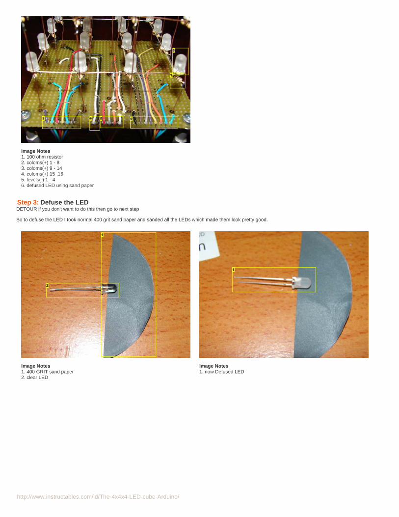
Image Notes1. 100 ohm resistor2. coloms(+) 1 - 83. coloms(+) 9 - 144. coloms(+) 15 ,165. levels(-) 1 - 46. defused LED using sand paper
Step 3: Defuse the LEDDETOUR if you don't want to do this then go to next step
So to defuse the LED I took normal 400 grit sand paper and sanded all the LEDs which made them look pretty good.
Image Notes1. 400 GRIT sand paper2. clear LED
Image Notes1. now Defused LED
http://www.instructables.com/id/The-4x4x4-LED-cube-Arduino/
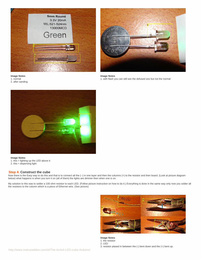
Image Notes1. normal2. after sanding
Image Notes1. with flash you can still see the defused one but not the normal
Image Notes1. this = lighting up the LED above it2. this = dispersing light
Step 4: Construct the cubeNow there is the Easy way to do this and that is to connect all the (--) in one layer and then the columns (+) to the resistor and then board. (Look at picture diagrambelow) what happens is when you turn it on (all of them) the lights are dimmer then when one is on.
My solution to this was to solder a 100 ohm resistor to each LED. (Follow picture instruction on how to do it.) Everything is done in the same way only now you solder allthe resistors to the column which is a piece of Ethernet wire. (See picture)
Image Notes1. the resistor2. LED3. resistor plased in between the (-) bent down and the (+) bent up.
http://www.instructables.com/id/The-4x4x4-LED-cube-Arduino/
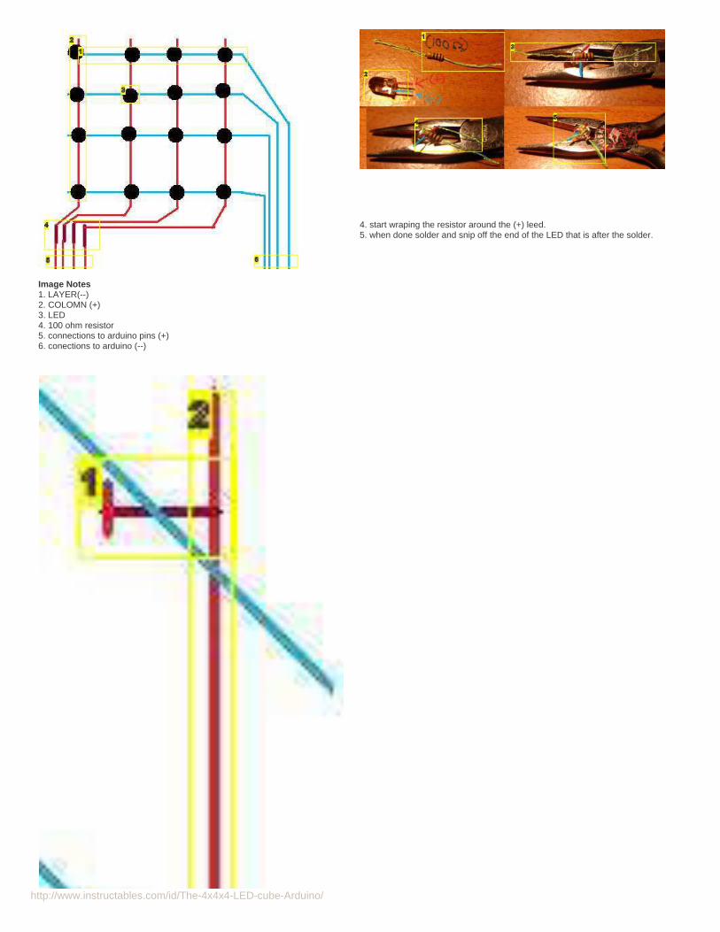
Image Notes1. LAYER(--)2. COLOMN (+)3. LED4. 100 ohm resistor5. connections to arduino pins (+)6. conections to arduino (--)
4. start wraping the resistor around the (+) leed.5. when done solder and snip off the end of the LED that is after the solder.
http://www.instructables.com/id/The-4x4x4-LED-cube-Arduino/
http://www.instructables.com/id/The-4x4x4-LED-cube-Arduino/
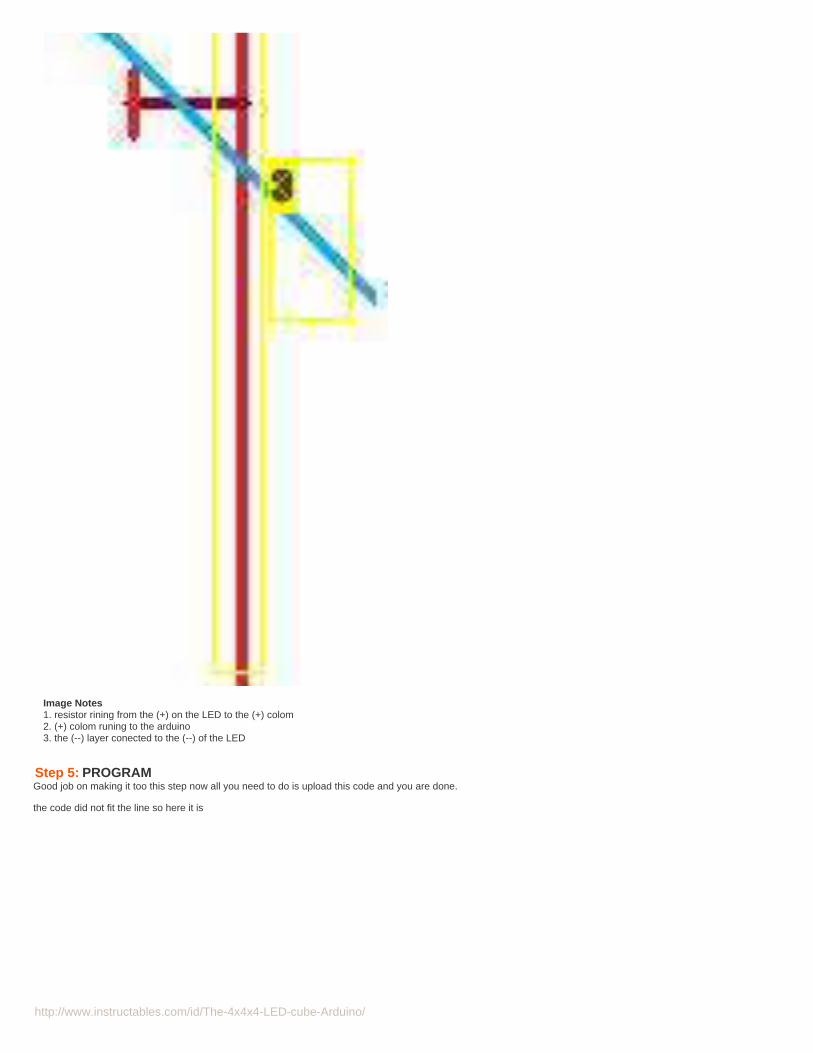
Image Notes1. resistor rining from the (+) on the LED to the (+) colom2. (+) colom runing to the arduino3. the (--) layer conected to the (--) of the LED
Step 5: PROGRAMGood job on making it too this step now all you need to do is upload this code and you are done.
the code did not fit the line so here it is

http://www.instructables.com/id/The-4x4x4-LED-cube-Arduino/
Image Notes1. All finished YAY took me about 4 days 2-5 hours a day to finish and program.
File Downloads
LED_cube_4x4x4.zip (2 KB)[NOTE: When saving, if you see .tmp as the file ext, rename it to 'LED_cube_4x4x4.zip']
Step 6: ADD onso to program the cube all you need to do is change the
B1111, B1111, B1111, B1111, B1111, B1111, B1111, B1111, B1111, B1111, B1111, B1111, B1111, B1111, B1111, B1111, 80,
codeeach B1111 corresponds to a line of LEDs in your cube 0 being off and 1 being on. The last number is the time it will display that part in milliseconds.
so get programing and enjoy.
Related Instructables
4x4x4 LED cubeby ElectronicsMan
Led Cube 4x4x4(video) by bajgik
LED Cube andArduino Lib bygzip
How to build an8x8x8 LED cubeand control itwith an Arduinoby R-
LED Cube 4x4x4by chr
Make a 24X6LED matrix bySyst3mX

http://www.instructables.com/id/The-4x4x4-LED-cube-Arduino/
Comments
50 comments Add Comment view all 51 comments
TheWaddleWaaddle says: Mar 14, 2011. 8:27 PM REPLY*Duemilanove
4and20chars says: Feb 21, 2011. 8:25 PM REPLYI love this instructable but I have a few questions. The first is, why did you not use transistors on the cathodes. The second question is how did you calculatethe resistor needed for each LED? Lastly, without resistors on the ground pins, is the arduino still protected or are they only needed with transistors. Sorry forthe long list, theses were the only things I was unsure of after scouring the internet. Thanks.
forte1994 says: Feb 24, 2011. 8:31 PM REPLY1) because the High setting on arduino is basicly + and the Low is - so i desided not to use transistors scince i can just turn on -.
2) its a website i found on google also i just generaly use 100 ohm even when the calculator says 73 or somthin just to be safe.
http://www.engplanet.com/content/resistorinfo.html
3) if i put resistors on the ground pins then the led wont light up because of the double resistance (2 x 100 ohm)
4and20chars says: Feb 25, 2011. 1:46 PM REPLYSo just to be clear, there is no (reasonable) chance of damaging the arduino or leds using your code and cube construction.
Electronics Man says: Feb 12, 2011. 6:02 AM REPLYWhich wires coming from the cube hook into the arduino pins? I have the cube built but I dont know where to connect the wires.
forte1994 says: Feb 21, 2011. 2:33 PM REPLYthe coloms to pins 0 - 13 analog in 0 - 1the layers to anlog in 5 - 2
supernova12 says: Feb 4, 2011. 12:54 PM REPLYThis cube is awesome, I just built it as my first project with my new arduino and it works great :). Thanks so much for the code, I honestly couldn't bebothered writing all the patterns myself.
forte1994 says: Feb 5, 2011. 5:03 PM REPLYGood job, and I did make a java app to write the code for you and you just check and ubchek boxes, its still a work in progress but does genorate thecode. I'll try to finish it asap and post it here.
the seaker says: Dec 29, 2010. 9:18 AM REPLYso basically what you're saying is thisB1111(column1), B1111(column2), B1111(column3), B1111(column4), B1111(column5), B1111(column6), B1111(column7), B1111(column8),B1111(column9), B1111(column10), B1111(column11), B1111(column12), B1111(column13), B1111(column14), B1111(column15), B1111(column16),80(time)
is how the code is set up?this is a great instructable. simple and educational.
ajmontag says: Jan 5, 2011. 11:29 PM REPLYIn my cube I use decoders and a bit of bitwise black magic:
/*** Displays the anode column with the given number value; [0, 24].*/void displayNum(int num){//constrain the argument to be between 0 and 24 inclusive.num = constrain(num, 0, 24);
/** AND: selects the bit, the bit at weight will be 1 if the pin is to be high* >>: shifts the selected bit to the end of the word, making the value a 0 or 1* first result is lsb* digitalWrite: write the approptiate result (HIGH or LOW)* to the appropriate decoder pin*/for(int weight=1, pin=0; pin < DECODER_BITS; weight*=2, pin++)digitalWrite(decoderPins[pin] ,(num & weight) >> pin);

http://www.instructables.com/id/The-4x4x4-LED-cube-Arduino/
//delay, this is the absoloute minimum time the light will be displayed.//ensures adequate delay for decoders as well.delayMicroseconds(MICRO);}
check it out at: http://www.instructables.com/id/LED-Cube-with-Arduino-and-custom-PCB/
forte1994 says: Dec 31, 2010. 10:08 AM REPLYum.. thats how its supposed to be, but don't count on it being exact it might be a row or a colom for me it was row it all depends on how you set it up.
thanks
the seaker says: Dec 31, 2010. 11:14 PM REPLYthanks
emihackr97 says: Dec 8, 2010. 3:46 PM REPLYi dont understand, doesn't Arduino only have 3 GROUND PINS??how cmoe you connect 4 different wires to it, please answer.
Mike32526 says: Dec 8, 2010. 5:30 PM REPLYthe 4 diff coms are so you can turn on an individual level with out turning on that whole colum of leds just the one on that level u wish to come on
Mike
emihackr97 says: Dec 8, 2010. 7:21 PM REPLYyeah, i know that, but, arent the Level pins supposed to be ground???as far as i know, those pins can supply V out but not gnd, in confused.Do you understand me??? can you explain me how these work??
Mike32526 says: Dec 8, 2010. 8:34 PM REPLYAll your pin on ur arduino can be manipulated to do any thing for example +5v (HIGH) or 0 volts (LOW) (gnd) by useing somryging like:digital.Write(2,LOW); Or something of that nature to tell the pin hey go gnd or go positive, Dont do this as a power Source!! As this will blow i/opins and/or the micro processor( the brain of it) Leds pull very little so they are semi safe to use. The resistor is to protect the arduino from the ledpulling to much as it limits the power it can draw from the pin.
The i/o pins are very universal in use i begin to love my arduino more and more every day!!
Mike
emihackr97 says: Dec 9, 2010. 8:02 PM REPLYthanks for the explanation, I thught that telling the pin to go LOW just disconnected it, but now I understand.also, I think that the resistor is not to protect the arduino, but the LEDs, since they are normally 3v and the Arduino is 5.
Mike32526 says: Dec 10, 2010. 5:49 AM REPLYthe led will pull alot of milli amps as well possible to over load the i/o pins capable out put so the resistor limits how much it can pull. yesalso protects led but the i/o pin isnt capable of suppling enough ma to blow the led any faster...
forte1994 says: Dec 11, 2010. 9:15 AM REPLYsrry i could not reply resently.good explanations and also yu do not need to put resistors on each led just the coloms.
ill be making an 8x8x8 soon (hopefully)and the resistor is like a 2 way protection:led --> arduino protects arduinoarduino --> led protects the led from burning out
hope this mekes it easier :-)thanks
Mike32526 says: Dec 11, 2010. 10:51 AM REPLYPost some videos id love to see it i to hope to make one that big i mave accomplished the 4x4x4 and is great
forte1994 says: Dec 31, 2010. 10:09 AM REPLYim working on the video just didnt have the time yet.
hopefully will have it soon

http://www.instructables.com/id/The-4x4x4-LED-cube-Arduino/
mackjr says: Dec 31, 2010. 9:29 AM REPLYmatrix specifically identity matrix like 1 0 00 1 00 0 1
the seaker says: Dec 28, 2010. 1:18 PM REPLYdid you use some sort of jig to create the layers? if so do you know how far the leds were apart?
emihackr97 says: Dec 11, 2010. 8:12 AM REPLYI'm making one today. Yay!
forte1994 says: Dec 11, 2010. 9:10 AM REPLYgood luck ;-)post some pictures of it later :-)
emihackr97 says: Dec 11, 2010. 10:45 PM REPLYyes, I couldn't finish it today but I have allready made all the layers, just need to attach it together.any tips to do this??
forte1994 says: Dec 17, 2010. 11:14 AM REPLY-put the second from botom layer in the jig and then match it with the next.
-then if you need to, bend the legs that are stiking up so that they easelyconnect to the next leyer
-put something to space them apart and solder the corners
-then remove the suports and solder evrything else
-rinse and repeat
-(ths way you do layer 1-2 then 1,2-3 then 1,2,3-4 4 being top)
good luck
emihackr97 says: Dec 19, 2010. 11:44 PM REPLYI made it a bit different and didn't add a resistor to each LED but to each column.
emihackr97 says: Dec 19, 2010. 11:43 PM REPLYI've allready finished, but i'm finishing my code so, when I finish it I will post some pics.
emihackr97 says: Dec 11, 2010. 10:48 PM REPLYcan you tell me in what pins does every column adr layer goes, please??
emihackr97 says: Dec 12, 2010. 10:56 AM REPLYI've catually figured it out from the code, thanks!
emihackr97 says: Dec 8, 2010. 3:52 PM REPLYor wouldn't you need transistors???
chr says: Dec 1, 2010. 6:23 AM REPLYHi forte1994,
Nice LED Cube! :)
I've built a few led cubes, and want to share some insights and design considerations.
1) There should be no need to have a resistor for each LED. If you use multiplexing, and it is working correctly, no more than one LED per column will be onat any given time.
2) I would recommend using an interrupt routine to do the multiplexing.
Create an buffer array of 4x4 bytes. (that way X and Y is the byte, and Z is the bits within the byte. It will save you 48 bytes of ram)
Set up a timer that runs every 10 milliseconds or something, and set up an interrupt routine that is called on every timer reset.

http://www.instructables.com/id/The-4x4x4-LED-cube-Arduino/
Every time the interrupt routine is called, it turns all layers off, loads the next layer from the buffer array onto the IO pins, and turns the next layer on. Rinseand repeat.
The cube now draws the buffer contents onto the LED cube in the background, and your main() loop can be preserved for code that generates animations.
I haven't tried using timers or interrupts on an Arduino before, but it shouldn't be very different from using them on a plain AVR.
You will also free up a lot of programming space by not having to store the patterns in program memory. I have ledcubes that run several minutes ofanimations on a 16KB avr.
You can also populate the cube buffer array via the serial line and control it from a computer.
Check out some code examples in my LED Cube instructable:
http://www.instructables.com/id/LED-Cube-4x4x4/
Hope you found this useful!
-chr
forte1994 says: Dec 4, 2010. 5:36 PM REPLYI found that for some reson some of the lights do not do multiplexing because I set up a camera that fillmed it and then played it back at VERY slowmotion.(by very slow I mean it was a 30 second video and I solowed it down to 30 min.)
thanks for the advise next I want to do a 8x8x8 and then 16x16x16 untill I can get to 64x64x64 :)
ReadyWater says: Nov 26, 2010. 6:48 AM REPLYAny chance the ingredients were purchased at Creatron in Toronto? The resistor bags and led info sheets look awfully familiar.
forte1994 says: Dec 4, 2010. 3:25 PM REPLYhehe YEP
forte1994 says: Sep 13, 2010. 10:30 PM REPLYDoes anyone now how to rate something (instructible ) before it was stars, what is it now?
Thanks in advance.
zascecs says: Nov 25, 2010. 9:13 AM REPLYYou go to the stars above someone's name, and then click on how many starts you think the person deserves ( From worthless, 0.5 starts, to best ever,5 stars).
If you're asking how many stars yours has, its 4.33 out of 5.
thomasofacton says: Nov 20, 2010. 3:02 PM REPLYI love it. I want to make one of these. But could you upload your code. When i do the copy and paste well arduino Ver 21 doesn't like it. Thanks again goodjob
forte1994 says: Nov 20, 2010. 6:56 PM REPLYok i changed the code and tested it and it works (the step wasnt alowing more text and cut it off)
thank you for noticing
mertaxoy says: Nov 8, 2010. 9:43 AM REPLYthere are many missing commands in program like this for (ledrow=0; ledrowcan i give us the code as a file please ?thank you..
zack247 says: Sep 12, 2010. 12:13 AM REPLYcool! i have always wanted to make a led cube, but i never found enough leds, maybe a 3x3x3 will be good enough for me.
PS: its spelled diffused, not defused, sorry if this came across as negative
forte1994 says: Sep 13, 2010. 10:21 PM REPLYNa I always make mistakes ( I'm only human) lol thanks

http://www.instructables.com/id/The-4x4x4-LED-cube-Arduino/
herpelcano says: Sep 9, 2010. 11:25 PM REPLYSince only one layer is on at a time you could have saved yourself a lot of trouble by only putting your resistors on the wires leading to the sixteen columns.
forte1994 says: Sep 10, 2010. 3:25 PM REPLYya at first i tried it with a 3x3x3 led cube and the colons would get considerably darker as more then one led on that colon turned on so thats why i did theextra work.
the seaker says: Sep 9, 2010. 9:03 AM REPLYmy last post was done when i was half asleep and i apoligize, i deleted it and ill start over. okay so if you do it your way using 20 pins, wouldnt lighting all theleds up draw more current than the arduino can put out?
herpelcano says: Sep 9, 2010. 11:23 PM REPLYThe authors cube is multiplexed which means only one layer it sixteen LEDs is on at any one time and they layers switch back and forth every couplemilliseconds to make it appear as if they are all on.
forte1994 says: Sep 9, 2010. 3:10 PM REPLYwell since each led is using its own 100 ohm resistor then i don't see why it would pull to much ( i don't know much about that stuff yet only grade 11) butthe Arduino works perfectly fine and all the leds have the same light out put.
the seaker says: Sep 10, 2010. 8:27 AM REPLYi am only grade 11 as well. and i see what you're saying, thanks for putting it that way because i some how managed to over look this simple fact.with both the arduino turning the leds on and off every couple milliseconds and the resistors, there wouldn't really be any way to go over the currentlimit of the arduino.
forte1994 says: Sep 13, 2010. 10:27 PM REPLYThere is actualy a way to see the led cube having one led on (at a time) while our eye sees the whole cube lit. Get a cammera and (don't knowmuch about cameras) and there is a setting that will make the cube look like it's flashing.That way it is way easier to understand it.
view all 51 comments