the 2009 mars telecom orbiter mission
TRANSCRIPT
1
The 2009 Mars Telecom Orbiter Mission1,2
Stephen F. Franklina, John P. Slonski, Jr.a, Stuart Kerridgea, Gary Noreena, Joseph E. Riedela, Tom Komareka, Dorothy
Stosica, Caroline Rachoa, Bernard Edwardsb, Don Borosonc
a-Jet Propulsion Laboratory, California Institute of Technology; Pasadena, Ca. 91109;
b-NASA Goddard Spaceflight Center, Greenbelt, Md. 20771 USA c-MIT-Lincoln Laboratory, Lexington, Ma, 02420
1 0-7803-8155-6/04/$17.00© 2004 IEEE 2 IEEE AC, Paper #1597, Version 0, October ,2004
Abstract—This paper provides an overview of the Mars Telecom Orbiter (MTO) mission, and is an update to the paper presented at last year’s conference. Launched in 2009, MTO will provide Mars-to-Earth relay services for NASA missions arriving at Mars between 2010 and 2020, enabling far higher science data return and lowering the telecom and operations costs for these missions. MTO carries an optical communications payload, which will demonstrate downlink bit rates from 1 Mbps up to and possibly exceeding 30 Mbps. MTO will also demonstrate the ability to autonomously navigate, and to search for and rendezvous with an orbiting sample, in preparation for NASA’s proposed Mars Sample Return Mission. A to-be-defined science instrument will also be carried.
TABLE OF CONTENTS
1. INTRODUCTION..................................................1 2. TRAJECTORY AND ORBIT TRADES ....................3 3. SPACECRAFT DESIGN DRIVERS .........................4 4. END-TO-END INFORMATION SYSTEM................6 5. RENDEZVOUS AND AUTONAV DEMONSTRATION8 6. ELECTRA UHF/X-BAND PAYLOAD .................12 6. LASER COMMUNICATIONS DEMO ...................14 8. CONCLUSION ...................................................16 REFERENCES .......................................................16 ACKNOWLEDGMENTS..........................................17
1. INTRODUCTION The 2009 Mars Telecom Orbiter (MTO) is the first mission in NASA’s plan to provide dedicated telecom relay capability from Mars science missions to Earth. MTO will greatly enhance the data return of Mars missions, as has been demonstrated by the successful relay of the two Mars Exploration Rover’s data by the MGS and Odyssey orbiters, which together have returned more than 94% of the rovers’ data. Last year’s 2004 IEEE aerospace conference paper of the same title (written by myself and others) presented an overview of the mission as defined one year ago. Substantial progress has been made on MTO’s mission definition since then, as described in the following paragraphs. MTO passed its Mission Concept Review in June and is now in phase A, preparing to issue its Request for Proposal for the spacecraft system contract.
Mission and flight system requirements have been written. The flight system requirements define the flight system performance and functionality to the competing system contract proposers. A Rendezvous and Autonomous Navigation (RAN) demonstration has been added. An orbiting sample canister will be released and tracked by the ground using on-board cameras. The spacecraft will then rendezvous with the canister using its autonomous navigation capability, coming to within ten meters of (but not capturing) the canister. This operation demonstrates capabilities that the proposed NASA Mars Sample Return orbiter will require to capture the Mars soil sample in its canister after it is launched into orbit around Mars. A science instrument will be flown, the Announcement of Opportunity for which is planned to be issued in December or January. The instrument is constrained by 5’s: it is to cost no more than $5M (not including accommodation), weigh no more than 5 kg and require no more than 5W power. The Mars Science Laboratory (MSL) mission launches in the same period as MTO and both will launch from Kennedy Space Center. The MTO mission Timeline is shown in Figure 1. Because of turn-around time constraints on the Atlas and Delta launch vehicles, the two launches must be separated by at least one week. Analysis of MSL’s and MTO’s arrival and launch constraints is ongoing. The answer will not be entirely optimal for either mission, but will provide MSL with a wide range of landing latitudes, allow MTO to arrive a month ahead in order to be commissioned prior to MSL’s arrival, and will allow both missions to stay within their launch vehicle budgets. Orbit selection work continues as a large number of circular and elliptical orbits are evaluated over many performance parameters, including total customer data return volume. MTO continues to carry its reference 5450 km altitude circular sun-synchronous 130 deg inclined orbit. The Mars Laser Comm Demonstration (MLCD) payload passed both its Mission Concept Review in January and System Requirements Review in October. The payload has
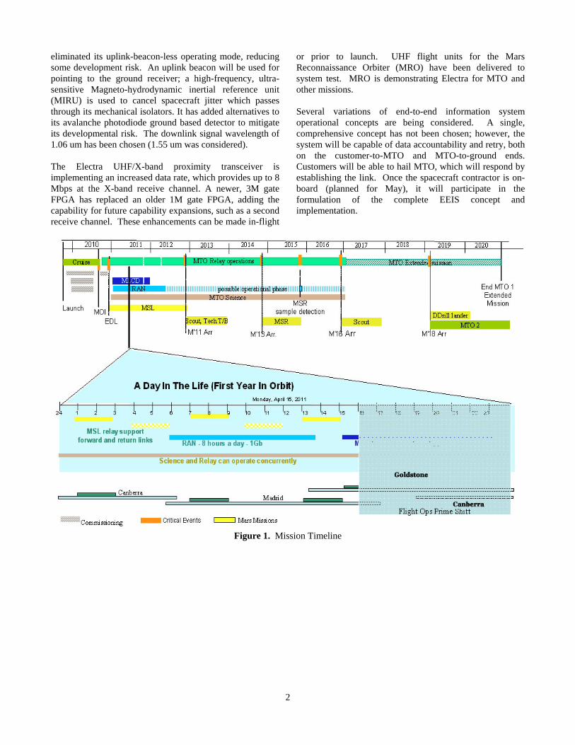
eliminated its uplink-beacon-less operating mode, reducing some development risk. An uplink beacon will be used for pointing to the ground receiver; a high-frequency, ultra-sensitive Magneto-hydrodynamic inertial reference unit (MIRU) is used to cancel spacecraft jitter which passes through its mechanical isolators. It has added alternatives to its avalanche photodiode ground based detector to mitigate its developmental risk. The downlink signal wavelength of 1.06 um has been chosen (1.55 um was considered). The Electra UHF/X-band proximity transceiver is implementing an increased data rate, which provides up to 8 Mbps at the X-band receive channel. A newer, 3M gate FPGA has replaced an older 1M gate FPGA, adding the capability for future capability expansions, such as a second receive channel. These enhancements can be made in-flight
or prior to launch. UHF flight units for the Mars Reconnaissance Orbiter (MRO) have been delivered to system test. MRO is demonstrating Electra for MTO and other missions. Several variations of end-to-end information system operational concepts are being considered. A single, comprehensive concept has not been chosen; however, the system will be capable of data accountability and retry, both on the customer-to-MTO and MTO-to-ground ends. Customers will be able to hail MTO, which will respond by establishing the link. Once the spacecraft contractor is on-board (planned for May), it will participate in the formulation of the complete EEIS concept and implementation.
Figure 1. Mission Timeline
2
3
2. TRAJECTORY AND ORBIT TRADES
Interplanetary trajectory - The launch and arrival dates for MTO are being coordinated with those of the Mars Science Laboratory Mission (MSL), which is also being launched in the 2009 Mars opportunity. Preliminary agreement has been reached with MSL on the launch and arrival dates required for its mission. The logistics at KSC will ultimately result from a negotiation between the projects, KSC and its launch vehicle providers. The arrival date separation required at Mars, between MTO and MSL will be decided by operations issues as well as details of mission and spacecraft implementation of the two projects. The current reference interplanetary trajectory satisfies the following constraints: 1. There must be at least a 7-day gap between the dual launch periods of MSL and MTO in 2009.
2. There must be a minimum arrival date separation at Mars of 30 days with MTO arriving before MSL.
Given these constraints, MTO has adopted a 20-day launch period beginning Sept. 22, 2009 with a maximum C3 of 13.9 km2/s2 and a maximum delta-v for Mars Orbit Insertion, MOI, of 676 m/s over the launch period. Arrival Dates vary from Aug. 13 to Aug. 23, 2010, across the launch period. Orbit Selection - A wide range of orbits is being considered for MTO. The criteria for final selection will include the following items: • Total delta-v to reach final orbit • Data throughput from typical landers anticipated to be
the main relay users • Ability to cover critical events such as EDL of landers
and MOI of orbiters • Spacecraft design considerations such as eclipse history • Mission and Spacecraft Operability.
The current state of orbit selection is best described by means of the classes of orbits that are being considered. Since the primary function of MTO is to provide relay coverage for Mars landers the relationship between the orbiter and a fixed ground location is critical. It is assumed that the ground location can be anywhere on Mars surface. All possible orbits into one of three possible categories:
1. Ground Track Repeating (GTR): these orbits cyclically repeat their pattern of coverage with respect to any (fixed) lander location. To date the length of the cycle has been adopted as one Martian day (1 sol) although there is nothing to prevent this length from being either longer or shorter than 1 sol. The integral number of orbit revolutions within the cycle length is denoted by a number Q. To date orbits between Q = 4 and Q = 8 have been studied in some detail. This results in a range of orbit periods and, therefore, a range of orbit altitudes. Generally these orbits are circular
but there is one unique elliptical orbit that was described in refer to last year’s version of this paper. 2. Quasi-GTR: these orbits are essentially the same as the GTR orbits except that their ellipticity drives a longer term variation about a mean repeat pattern. This long term variation is due to the argument of periapse steadily walking around the whole 360 deg. of true anomaly of the orbit. Since the eccentricities considered are fairly small (< 0.3) this variation is small compared to the gross variation of passes from one revolution to the next within the shorter cycle time. Since the periodicity of the argument of periapse is generally many hundreds of sols some of these orbits can be treated over some period of time (many sols) as if they are actually GTR in nature.
3. Non-GTR orbits: these orbits have no short term repeatability of pass coverage for landers. Two subclasses of these orbits have been looked at. The first are circular orbits whose periodicity is not related in a rational way to the rotation period of Mars. The second are orbits that maintain their line of apsides in a constant relationship to the Mean Sun defined at Mars. In the literature maybe Ted Sweetser can provide a ref. these are known as Sunwalker orbits. For Mars they are potentially useful for landers that require either long (but distant) Apoapse passes or short (and close) Periapse passes with the selected pass always being in daylight to enable relay from a solar powered lander.
Since this categorization really only addresses criterion #2 in the above listing a few words are in order regarding other orbit classes related to some of the remaining criteria.
Design and operation of spacecraft is often facilitated by selecting an orbit to be Sun-synchronous. This generally means that the line of nodes, and hence the plane of the MTO orbit, maintains a nearly-constant orientation with respect to solar illumination. All orbits studied to date have been designed to be sun-synchronous. It is anticipated that this informal guideline will be violated in coming studies in order to address the full range of criteria for orbit selection.
Critical events coverage of other Mars missions is best facilitated by selecting orbits that are some 1000s rather than the 100s of kms above Mars surface. This is generally true of Mars science orbiters such as Odyssey (ODY) and Mars Reconnaissance Orbiter (MRO). ODY has productively supported relays for the Mars Exploration Rovers, Spirit and Opportunity, and both ODY and MRO are likely to be used by MSL for some relay, neither orbit is particularly effective in global access to isolated events at specific epochs as characterizes Critical Events of Mars missions. This drives MTO to select a higher orbit than is historically true for other Mars orbiters. The issue of the total DV required for a selected orbit is a complex one since it depends primarily on the size (read semi-major axis) of the orbit and its eccentricity.
4
Beneficially it requires less DV to get into a larger orbit than a smaller one of the same eccentricity. Thus MTO’s preference for higher altitudes is helpful in this regard. However at a fixed orbit size (read semi-major axis) it requires less and less DV to get into an orbit of higher and higher eccentricity. Although this may seem acceptable, there arises potential conflict with the need for an orbit to provide adequate relay support over the whole of Mars.
By its very nature, an elliptical orbit provides preferential coverage to some areas of the planet and something less than this to others. Since the missions likely to need support in the 10 year orbital phase of MTO will generally not be defined until well after MTO is designed, built and (even) flown, it makes it problematic on how best to orient an elliptical orbit above Mars. When coupling this fact with the limited ability of MTO to modify its orbit shape and size during its orbital phase (due to limited propellant allocated to this) we may end up providing less than useful coverage to some future landers. Alternatively it could drive the project to over design the capabilities of the spacecraft so that not even the less attractive parts of an elliptical orbit would still be satisfactory for all future missions.
Having said all this a large number of elliptical orbits have been studied in detail larger DV leads to larger launch masses for spacecraft and this in turn leads to higher costs. In a severely restricted budgetary climate it behooves the MTO project to seek all possible ways to reduce spacecraft mass and particularly includes the need to address the adequacy of orbits needing less DV to reach them.
A single orbit has remained the reference orbit for MTO for at least the past two years. It is circular at an altitude of 4450 km and an inclination of 130 deg. This orbit can access the whole of the Martian surface. It is sun-synchronous although there is currently no project requirement for the node to be at any particular Local Mean Solar Time. This latter parameter will be determined by the nature of the interplanetary trajectory approaching Mars. This orbit was early determined to be particularly attractive both due to its high altitude for Critical Event coverage and its pattern of coverage for relay. It turns out that the latter results in nearly a constant relay data throughput over all latitudes on Mars, potentially a useful attribute for unknown future landing sites.
Reference Mission Scenario - A reference scenario has been developed for progressing from the initial orbit achieved at MOI to the first operational (for routine relay) orbit: 1. MOI occurs at an altitude of 250 km and the initial orbit is sized to an period equal to 5 sols. This is called the Initial Orbit. Advantage is gained in a DV sense by selecting a larger orbit than 1-sol that the Project considered earlier.
2. About 2 weeks after MOI a maneuver is performed at apoapse of the Initial Orbit to raise periapse up to the altitude required in the final orbit, viz., 4450 km. This is called the Intermediate Orbit.
3. About 4 weeks after the periapse-raise maneuver a second maneuver is executed at periapse of the Intermediate Orbit to lower apoapse to its final altitude of 4450 km. The orbit achieved is called the Initial Service Orbit.
This 3-burn strategy is optimal for propellant usage.
In this scenario it is the Intermediate Orbit that would be utilized for EDL coverage of MSL should it arrive 30 days after MTO. This scenario is being revisited to determine if it would be beneficial to be in the Initial Service Orbit prior to MSL’s arrival. There appear to be no navigation issues that would preclude either option.
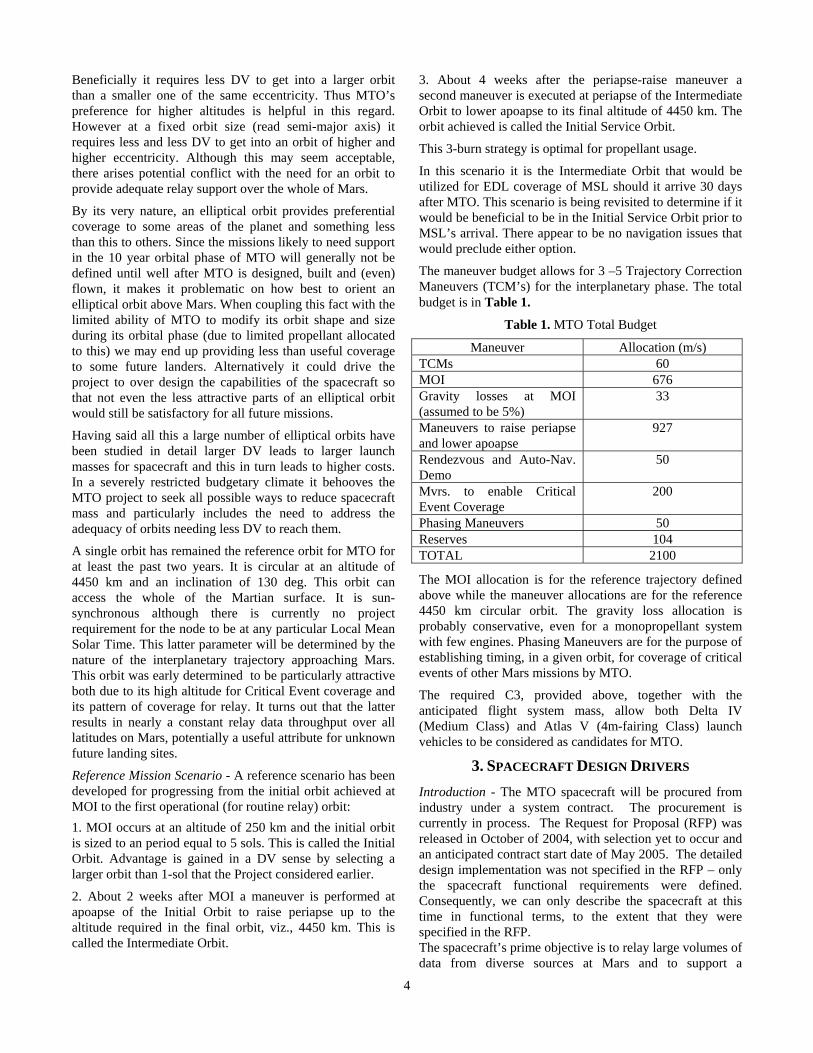
The maneuver budget allows for 3 –5 Trajectory Correction Maneuvers (TCM’s) for the interplanetary phase. The total budget is in Table 1.
Table 1. MTO Total Budget
Maneuver Allocation (m/s) TCMs 60 MOI 676 Gravity losses at MOI (assumed to be 5%)
33
Maneuvers to raise periapse and lower apoapse
927
Rendezvous and Auto-Nav. Demo
50
Mvrs. to enable Critical Event Coverage
200
Phasing Maneuvers 50 Reserves 104 TOTAL 2100
The MOI allocation is for the reference trajectory defined above while the maneuver allocations are for the reference 4450 km circular orbit. The gravity loss allocation is probably conservative, even for a monopropellant system with few engines. Phasing Maneuvers are for the purpose of establishing timing, in a given orbit, for coverage of critical events of other Mars missions by MTO.
The required C3, provided above, together with the anticipated flight system mass, allow both Delta IV (Medium Class) and Atlas V (4m-fairing Class) launch vehicles to be considered as candidates for MTO.
3. SPACECRAFT DESIGN DRIVERS Introduction - The MTO spacecraft will be procured from industry under a system contract. The procurement is currently in process. The Request for Proposal (RFP) was released in October of 2004, with selection yet to occur and an anticipated contract start date of May 2005. The detailed design implementation was not specified in the RFP – only the spacecraft functional requirements were defined. Consequently, we can only describe the spacecraft at this time in functional terms, to the extent that they were specified in the RFP. The spacecraft’s prime objective is to relay large volumes of data from diverse sources at Mars and to support a
5
planetary-distance, high rate, laser communications demonstration at Mars (MLCD). In addition, the spacecraft will support a rendezvous and autonomous navigation (RAN) demonstration payload, plus carry a 100 watt Ka-band traveling wave tube amplifier assembly (TWTA) as a technology demonstration.
Basic Spacecraft Operations - The spacecraft will be launched in 2009 and arrive at Mars in 2010 after approximately 11 months of cruise. The spacecraft will be launched on either a Delta IV or Atlas V vehicle, due primarily to its large propellant load. The spacecraft will be carrying more than half its mass as propellant, and will be capable of providing more than 2100 m/s of velocity change (ΔV). Launch energy requirements and launch vehicle capabilities will limit the launch mass to approximately 3000 kg. During cruise, the spacecraft will perform the usual propulsive course corrections and hardware calibrations, including checkout and calibration of the RAN cameras and possibly the UHF proximity antenna. In addition, the 100 watt Ka-band TWTA will be used periodically, and the MLCD will be extensively operated and calibrated, so that it is ready to operate at Mars.
Relay Operations - The primary role of the spacecraft is to support relay operations from/to other Mars craft, including landers, rovers, aerobots, and orbiters. To support this, the spacecraft carries a two-way proximity relay radio subsystem named Electra. Electra will be first flown on the Mars Reconnaissance Orbiter (MRO), which is being launched in 2005. The version being used by the MTO spacecraft is essentially the same design, with a somewhat higher data rate handling capability and the addition of an X-band receiver, to provide higher link performance. In addition to two-way data capability at UHF frequencies and receive-only capability at X-band, Electra provides corresponding metric tracking (i.e. Doppler) capabilities at these frequencies. Electra implements the Proximity-1 protocol defined by the Consultative Committee on Space Data Systems (CCSDS). The other element supporting relay operations is the spacecraft radio frequency link with the Deep Space Network (DSN) on earth. The data received from other Mars craft by Electra will be stored onboard the spacecraft for later transmission to the DSN via X-band and Ka-band links. Immediate playback of the stored data is possible, if there is DSN coverage at the time of relay data receipt, which yields the equivalent of a “bent pipe” mode. Ka-band is being used to carry bulk science data, because of its efficient high data rate capability. Ka-band performance, however, is more sensitive to terrestrial weather degradation, so X-band is used to carry health and safety telemetry plus high priority data needed to plan the near term activities of user Mars craft. Another reason to use Ka-band is the rate limitation placed on X-band due to channel spectrum considerations for spacecraft operating at Mars. Because of this limitation, the maximum data rate allowable for the Quadrature Phase Shift Keying (QPSK)
modulation system used by the MTO spacecraft is on the order of 500 kbps. No such limitation exists for Ka-band, and the maximum data rate planned for this link is 4000 kbps. The actual link performance could support in excess of 20 Mbps at minimum earth – Mars range, but the short periods for which this is possible do not justify requiring the spacecraft data system to support it. The data rates that will be supported over the spacecraft to DSN links at maximum range are 350 kbps and 35 kbps over Ka-band and X-band, respectively. Assuming a daily 8-hour DSN pass, MTO should be able to relay at least 10 gigabits/day to earth from the various Mars craft MTO will be supporting.
The MTO spacecraft will be capable of regularly supporting Mars craft operating on the surface or above the surface up to an altitude of 500 km. In addition, it will be able to support, on an occasional basis, critical activities of Mars craft anywhere in the vicinity of the planet. These activities include entry, descent, and landings (EDL), orbit insertions, launch of Mars ascent vehicles, and orbital rendezvous. Also, the spacecraft will be capable of acquiring metric tracking data from an incoming spacecraft that is within approximately 30 days of arrival.
Data acquired by the spacecraft from user Mars craft will be transmitted to the DSN in a priority ordered fashion. The received user data will in general contain embedded meta-data which will be used by the spacecraft to determine which data will be transmitted first and also which frequency channel, X or Ka, is to be used. The onboard algorithm which regulates this process will also handle retransmission requests from the ground system. The onboard algorithm will be programmable, so that it can be updated over the spacecraft 10 year mission as its user set changes and their mission phases evolve with time.
Relay data files will be handled according to the CCSDS file delivery protocol (CFDP), with retransmissions requested by the ground system when link dropouts occur. Ka-band data rates will be set with lower margins and, therefore, higher link error rates than normally used at X-band, in order to optimally take advantage of retransmissions and to operate the link closer to its maximum capacity. Onboard data storage will act as a buffer in this system. This mass storage is sized at 350 gigabits, which allows accumulation without data loss during an extended weather-induced DSN outage of up to four days (corresponds to <5 day data reception delay).
Laser Communications Operations - The spacecraft’s primary role in supporting the MLCD is to provide coarse pointing and a stable platform for the onboard Mars Lasercom Terminal (MLT). Because there are two fine pointing systems within the MLT, the pointing control requirement that the spacecraft has to support is only 4 milliradians. The MLT incorporates an instrument adjustment mechanism (IAM) and a fast steering mirror (FSM), which “home” the transmitted signal to a beacon signal transmitted from the MLCD ground station. The former moves the entire MLT optical module and
6
compensates for long term spacecraft changes affecting MLT boresight pointing, while the latter compensates for higher frequency deviations in spacecraft attitude control.
Because of the inability of the latter to respond to spacecraft jitter, e.g. due to stepper motors or reaction wheel motors, the spacecraft must meet stringent short-term angular disturbance and linear acceleration specifications. In addition to meeting the pointing and jitter requirements, the spacecraft will provide the MLT processor in real time with current attitude and ephemeris information. The MLT uses this information to calculate a “point ahead” correction relative to the beacon signal, which will allow its very narrow beam to arrive at the ground station one round-trip light time after the ground station beacon signal was transmitted. To support the MLCD objective of demonstrating the return of science data from Mars over an optical link, the spacecraft will provide the MLT with access to the data stored in spacecraft mass storage, using a transfer rate in the range of 5 – 10 Mbps.
Operationally, the spacecraft is required to transmit health and safety data, including MLT engineering telemetry, over the X-band link simultaneous with transmission of the MLT signal. It is also intended to continue transmitting bulk relay data over the Ka-band link during MLT operations, so that support to Mars craft is not affected by MLCD operations. Support of simultaneous operation of all three links will be possible because of co-alignment of the X-band and Ka-band electrical boresights, plus inflight co-alignment of the MLT optical boresight, which is made possible by the IAM system. Simultaneous use of the proximity relay link to acquire data from Mars craft may be precluded, however, if there is relay antenna articulation that generates too much jitter. Providing power resources for operating all the links is not a problem, though, because the MLCD primary mission is planned for the first year in orbit, before the worst-case sun range occurs. The solar array size is driven by non-MLCD operations later in the mission.
Rendezvous/Autonomous Navigation Operations - The spacecraft will carry a RAN payload consisting of two gimbaled camera assemblies, avionics, and a deployable orbital sample canister (OSC). The avionics include a capable processor for conducting autonomous operations, which consist of rendezvous and orbital navigation, plus electronics to control the gimbals. The OSC simulates the sample canister that will be used in the Mars Sample Return mission, and will be used to validate the detection and rendezvous techniques that are planned for it.
The spacecraft’s function in the autonomous rendezvous phase is to accept sequencing, attitude control, and propulsive ΔV requests from the RAN processor, allowing the spacecraft to autonomously rendezvous with the deployed OSC (to within 10 m). Initial detection of the deployed OSC, however, will be accomplished by ground scheduled imaging, with the OSC orbit determined by ground analysis of the returned images. To enable close
rendezvous, the spacecraft will have small thrusters configured to permit combinations of them to be fired simultaneously such that the resultant thrust vector can be in any direction without having to reorient the spacecraft (“vector mode thrusting”). There will be on the order of 12 separate rendezvous demonstrations conducted during the MTO mission, requiring a total ΔV allocation of 50 m/s.
The spacecraft’s function in the autonomous navigation phase is similar to autonomous rendezvous. The spacecraft will be capable of accepting sequencing and propulsive ΔV requests from the RAN processor, with the difference being that the objective would be to perform autonomous orbit trim maneuvers consisting of turn-and-burn propulsive events. Before the orbit trims are performed, the RAN processor will by itself acquire images of surface landmarks and of the Martian satellites, perform orbit determination calculations based on these images, and transmit the results to the ground for validation.
Miscellaneous - The spacecraft will operate in operational orbits subject to solar eclipse. Current constraints on orbit selection limit the maximum eclipse duration to 50 minutes per orbit. Due to the likelihood that the operational orbits will be sun synchronous, the eclipse season is long. One orbit that has been studied had eclipses of up to 48 minutes every orbit for approximately 400 consecutive days per Martian year. The spacecraft battery will be sized to limit its depth of discharge so that it can survive this type of cycle over the 10 year mission. Redundancy will exist, either at the cell level or battery level, to allow full functionality in the event of a random cell failure.
The 100 watt Ka-band TWTA will be periodically operated in place of the spacecraft’s Ka-band transmitter, when power resources permit. There are no special data rates to be used during this demonstration, since the received signal level itself is sufficient to determine tube output performance.
The spacecraft will carry a science instrument, although the science investigation which it will support has not yet been selected. The investigation and the instrument will necessarily have to be compatible with the orbits and spacecraft orientations designed for the relay operations.
4. END-TO-END INFORMATION SYSTEM The MTO End-to-End Information System (EEIS) is the set of functions distributed across the flight, ground, launch, and mission operation systems that interoperate cooperatively to collect and transport, store, translate, integrate, and manage mission information. These functions are performed cooperatively by flight and ground elements to manage, control and achieve mission objectives.
MTO EEIS includes telemetry flow through all subsystems from data transmission from a user Marscraft3, through the MTO spacecraft, on to the Deep Space Network (DSN), the
3An aerobot, lander, rover or orbiter in the vicinity of Mars.
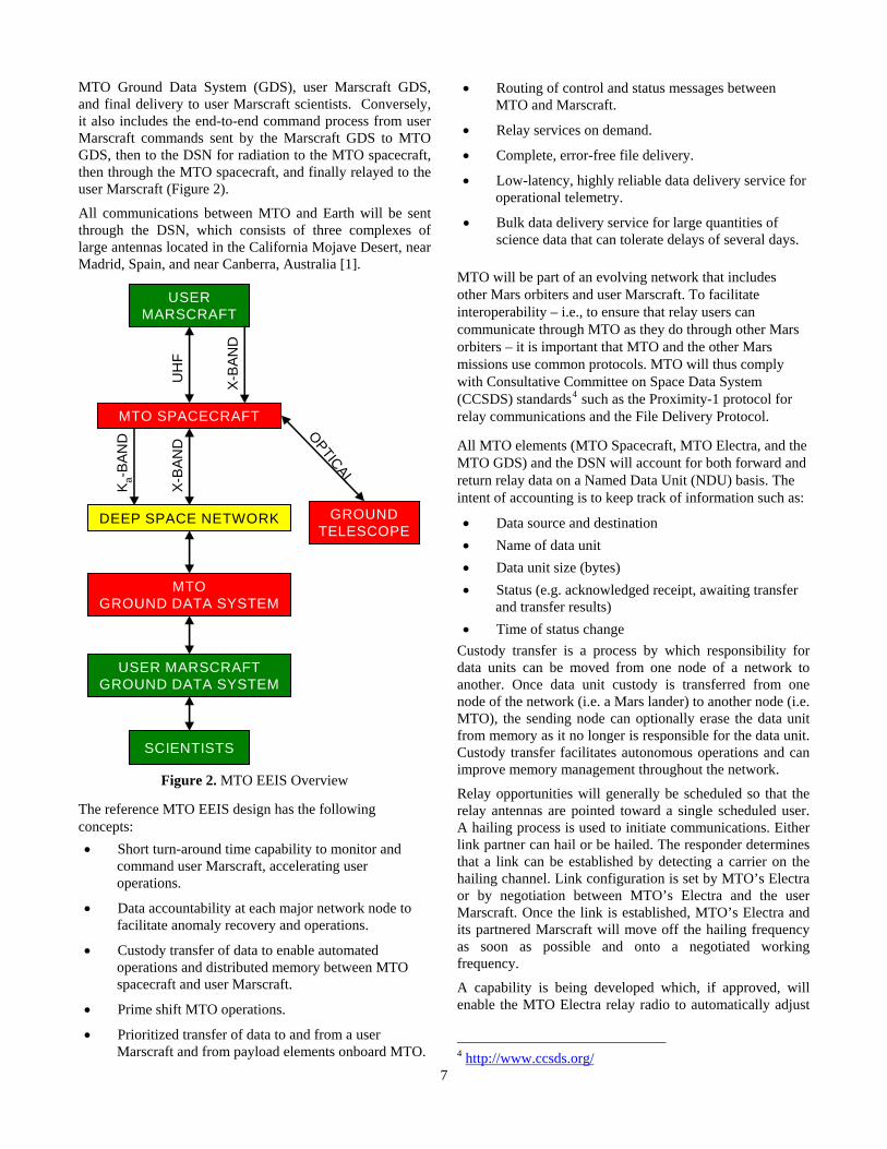
MTO Ground Data System (GDS), user Marscraft GDS, and final delivery to user Marscraft scientists. Conversely, it also includes the end-to-end command process from user Marscraft commands sent by the Marscraft GDS to MTO GDS, then to the DSN for radiation to the MTO spacecraft, then through the MTO spacecraft, and finally relayed to the user Marscraft (Figure 2).
All communications between MTO and Earth will be sent through the DSN, which consists of three complexes of large antennas located in the California Mojave Desert, near Madrid, Spain, and near Canberra, Australia [1].
USERMARSCRAFT
MTO SPACECRAFT
DEEP SPACE NETWORK
MTOGROUND DATA SYSTEM
USER MARSCRAFTGROUND DATA SYSTEM
UH
F
X-B
AND
X-B
AND
K a-BA
ND
GROUNDTELESCOPE
OPTICAL
SCIENTISTS
Figure 2. MTO EEIS Overview
The reference MTO EEIS design has the following concepts: • Short turn-around time capability to monitor and
command user Marscraft, accelerating user operations.
• Data accountability at each major network node to facilitate anomaly recovery and operations.
• Custody transfer of data to enable automated operations and distributed memory between MTO spacecraft and user Marscraft.
• Prime shift MTO operations.
• Prioritized transfer of data to and from a user Marscraft and from payload elements onboard MTO.
• Routing of control and status messages between MTO and Marscraft.
• Relay services on demand.
• Complete, error-free file delivery.
• Low-latency, highly reliable data delivery service for operational telemetry.
• Bulk data delivery service for large quantities of science data that can tolerate delays of several days.
MTO will be part of an evolving network that includes other Mars orbiters and user Marscraft. To facilitate interoperability – i.e., to ensure that relay users can communicate through MTO as they do through other Mars orbiters – it is important that MTO and the other Mars missions use common protocols. MTO will thus comply with Consultative Committee on Space Data System (CCSDS) standards4 such as the Proximity-1 protocol for relay communications and the File Delivery Protocol.
All MTO elements (MTO Spacecraft, MTO Electra, and the MTO GDS) and the DSN will account for both forward and return relay data on a Named Data Unit (NDU) basis. The intent of accounting is to keep track of information such as:
• Data source and destination • Name of data unit • Data unit size (bytes) • Status (e.g. acknowledged receipt, awaiting transfer
and transfer results) • Time of status change
Custody transfer is a process by which responsibility for data units can be moved from one node of a network to another. Once data unit custody is transferred from one node of the network (i.e. a Mars lander) to another node (i.e. MTO), the sending node can optionally erase the data unit from memory as it no longer is responsible for the data unit. Custody transfer facilitates autonomous operations and can improve memory management throughout the network.
Relay opportunities will generally be scheduled so that the relay antennas are pointed toward a single scheduled user. A hailing process is used to initiate communications. Either link partner can hail or be hailed. The responder determines that a link can be established by detecting a carrier on the hailing channel. Link configuration is set by MTO’s Electra or by negotiation between MTO’s Electra and the user Marscraft. Once the link is established, MTO’s Electra and its partnered Marscraft will move off the hailing frequency as soon as possible and onto a negotiated working frequency.
A capability is being developed which, if approved, will enable the MTO Electra relay radio to automatically adjust
4 http://www.ccsds.org/
7
8
the return link relay data rate during a pass in response to changing link conditions.
MTO will transmit prioritized data acquired from multiple Marscraft to Earth based on programmable parameter-based rules specified by the Ground System, including:
• Source of the data, • Emergency flag, • Age of the data, and • Length of time the data was stored onboard MTO.
MTO will provide two basic return link delivery services: low latency and bulk data. A single relay user can use both services simultaneously.
The low latency delivery service will send MTO and user Marscraft data to Earth with high reliability and minimal delay (one way light time plus a few minutes if the DSN is tracking). This service will be used for MTO and user Marscraft health and safety telemetry and data needed for user Marscraft operational planning purposes. The low latency delivery service will be provided over X-band Direct-To-Earth (DTE) links with high margin to maximize the probability of reliable delivery on the first transmission.
The bulk data delivery service will transfer large quantities of user Marscraft data to Earth with high reliability but potentially long latency (as long as 5 days). This service will be provided over Ka-band DTE links, which are susceptible to weather, with minimal margin; lost data will be retransmitted.
5. RENDEZVOUS AND AUTONAV
DEMONSTRATION The MTO mission, as part of it suite of technology demonstrations will fly and operate RAN, the Rendezvous and Autonomous Navigation demonstration. The RAN Tech Demo will prove two closely linked and dependent technologies, autonomous rendezvous on Mars orbit, and autonomous optical navigation. The principal objectives of the RAN demonstration are 1) to perform a rendezvous demonstration to prove MSR-required rendezvous technologies, and 2) demonstrate autonomous navigation capabilities to establish an in-orbit Mars autonomous navigation infrastructure to provide reliable and reduced-cost Mars operations. The RAN system is composed of a largely self-contained and integrated hardware and software suite, including two MRO-based Narrow Angle Cameras (NAC’s), a CPU, two 2-D gimbals, two gimbal controllers, two wide angle cameras, and a substantially upgraded version of the Deep Space 1/Deep Impact Autonomous
Navigation (AutoNav) software. Also included, but not part of the integrated hardware/software suite is a sample orbiting canister (OSC) and carrier/release-once mechanism with a small one-way UHF beacon (primary battery powered) contained in the OSC.
The AutoNav component of RAN undertakes demonstration activities throughout the mission, culminating – perhaps late in the orbital mission or extended mission – with extended periods of fully autonomous navigation operations. AutoNav uses images taken by the NAC’s to perform Orbit Determination (OD) and Maneuver Planning (MP). With the integrated nature of the RAN s/w and h/w, these efforts can largely occur without impact to other s/c operations. Interfaces into the RAN system are minimal, and include a suite of less than 20 commands, data file transfers, and regular s/c attitude reports. Interfaces out of RAN include data files, telemetry data, and automatically generated sequences for execution of trajectory correction maneuvers (TCM’s) and Orbit Trim Maneuvers (OTM’s). Before the system is validated, RAN requests for s/c action will be reviewed by ground operations before they can take effect.
The rendezvous component of the RAN demo commences in the Spring or Summer of 2011 (6 to 9 months after MOI), with release of the OSC. For the following approximately 6 months, RAN performs a series of experiments where the range to the OSC is variously manually and autonomously maintained and changed with a dozen events where the range is reduced to less than 10m. Autonomous tracking and maneuvering is accomplished by the RAN AutoNav system. Also during this several month period the range to the OSC will be increased to several (e.g. 7) thousand km, for purposes of demonstrating long-range detection and tracking in support of MSR technology and mission operations.
Figure 3 gives a general and schematic description of the RAN rendezvous mission design, especially those operations associated with a dozen or so “capture sorties” which will take place over the 6 months of the primary demonstration mission. In this approximately 1 week series of events, the range of the spacecraft to the OSC varies from up to 10km to within 10m. Throughout this time, optical observables are taken with the narrow angle cameras, supplemented at close range with data from the wide angle cameras. The spacecraft is, via combinations of closed-loop and autonomous control, put into a series of co-elliptic and circumnavigating orbits relative to the OSC. Also, Figure 3 shows the method of achieving the long ranges to the OSC necessary for the search phase of the demonstration. Additionally noted are the contrasts in timing and geometry between the MTO demonstration and the MSR activities.
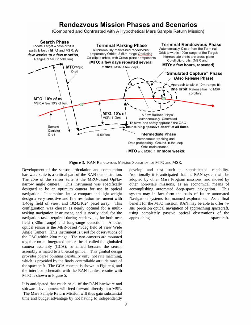
Figure 3. RAN Rendezvous Mission Scenarios for MTO and MSR.
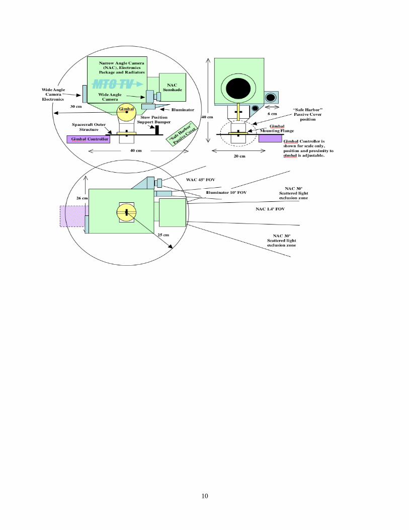
Development of the sensor, articulation and computation hardware suite is a critical part of the RAN demonstration. The core of the sensor suite is the MRO-based OpNav narrow angle camera. This instrument was specifically designed to be an optimum camera for use in optical navigation. It combines into a compact and light weight design a very sensitive and fine resolution instrument with 1.4deg field of view, and 1024x1024 pixel array. This configuration was chosen as nearly optimal for a multi-tasking navigation instrument, and is nearly ideal for the navigation tasks required during rendezvous, for both near field (>20m range) and long-range detection. Another optical sensor is the MER-based 45deg field of view Wide Angle Camera. This instrument is used for observations of the OSC within 20m range. The two cameras are mounted together on an integrated camera head, called the gimbaled camera assembly (GCA), so-named because the sensor assembly is mated to a bi-axial gimbal. This gimbal design provides coarse pointing capability only, not rate matching, which is provided by the finely controllable attitude rates of the spacecraft. The GCA concept is shown in Figure 4, and the interface schematic with the RAN hardware suite with MTO is shown in Figure 5.
It is anticipated that much or all of the RAN hardware and software development will feed forward directly into MSR. The Mars Sample Return Mission will thus gain substantial time and budget advantage by not having to independently
develop and test such a sophisticated capability. Additionally it is anticipated that the RAN system will be adopted by other Mars Program missions, and indeed by other non-Mars missions, as an economical means of accomplishing automated deep-space navigation. This system may in fact form the basis of future automated Navigation systems for manned exploration. As a final benefit for the MTO mission, RAN may be able to offer in-situ precision optical navigation of approaching spacecraft, using completely passive optical observations of the approaching spacecraft.
9
10
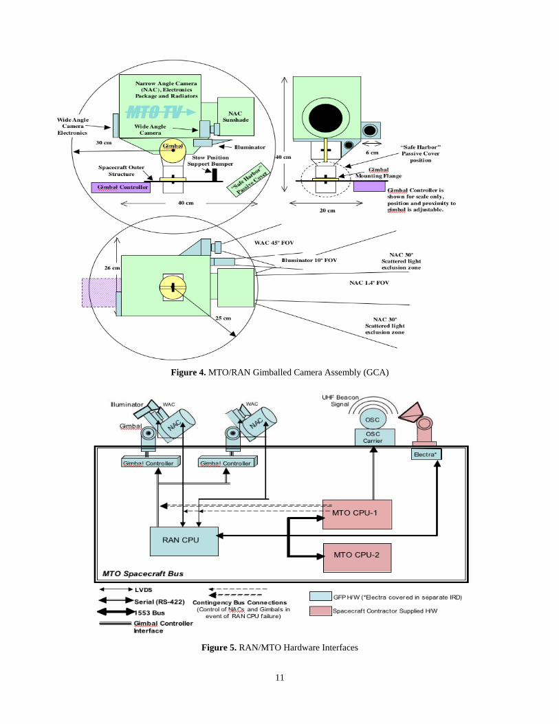
Figure 4. MTO/RAN Gimballed Camera Assembly (GCA)
Figure 5. RAN/MTO Hardware Interfaces
11
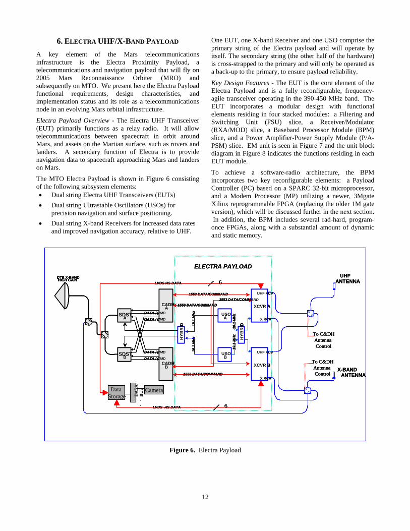
6. ELECTRA UHF/X-BAND PAYLOAD One EUT, one X-band Receiver and one USO comprise the primary string of the Electra payload and will operate by itself. The secondary string (the other half of the hardware) is cross-strapped to the primary and will only be operated as a back-up to the primary, to ensure payload reliability.
A key element of the Mars telecommunications infrastructure is the Electra Proximity Payload, a telecommunications and navigation payload that will fly on 2005 Mars Reconnaissance Orbiter (MRO) and subsequently on MTO. We present here the Electra Payload functional requirements, design characteristics, and implementation status and its role as a telecommunications node in an evolving Mars orbital infrastructure.
Key Design Features - The EUT is the core element of the Electra Payload and is a fully reconfigurable, frequency-agile transceiver operating in the 390-450 MHz band. The EUT incorporates a modular design with functional elements residing in four stacked modules: a Filtering and Switching Unit (FSU) slice, a Receiver/Modulator (RXA/MOD) slice, a Baseband Processor Module (BPM) slice, and a Power Amplifier-Power Supply Module (P/A-PSM) slice. EM unit is seen in Figure 7 and the unit block diagram in Figure 8 indicates the functions residing in each EUT module.
Electra Payload Overview - The Electra UHF Transceiver (EUT) primarily functions as a relay radio. It will allow telecommunications between spacecraft in orbit around Mars, and assets on the Martian surface, such as rovers and landers. A secondary function of Electra is to provide navigation data to spacecraft approaching Mars and landers on Mars.
To achieve a software-radio architecture, the BPM incorporates two key reconfigurable elements: a Payload Controller (PC) based on a SPARC 32-bit microprocessor, and a Modem Processor (MP) utilizing a newer, 3Mgate Xilinx reprogrammable FPGA (replacing the older 1M gate version), which will be discussed further in the next section. In addition, the BPM includes several rad-hard, program-once FPGAs, along with a substantial amount of dynamic and static memory.
The MTO Electra Payload is shown in Figure 6 consisting of the following subsystem elements: • Dual string Electra UHF Transceivers (EUTs) • Dual string Ultrastable Oscillators (USOs) for
precision navigation and surface positioning. • Dual string X-band Receivers for increased data rates
and improved navigation accuracy, relative to UHF.
SDSTA
SDSTB
C&DHA
C&DHB
DATA / CMD
DATA / CMD
DATA / CMD
DATA / CMD
USOA
USOB
HYB
RID
XCVR A
XCVR B
19.1
MH
z19
.1 M
Hz
19.1
MH
z19
.1 M
Hz
DTE X-BANDHIGH GAIN
ELECTRA PAYLOAD
HYB
RID
UHF XCV
X RCV
UHF XCV
X RCV
X-BANDANTENNA
UHFANTENNA
1553 DATA/COMMAND
1553 DATA/COMMAND
Data Storage D
ATA
B
US Camera
LVDS HS DATA
LVDS HS DATA
1553 DATA/COMMAND 1553 DATA/COMMAND
To C&DHAntenna Control
To C&DHAntenna Control
6
6
.
.
.
Figure 6. Electra Payload
12
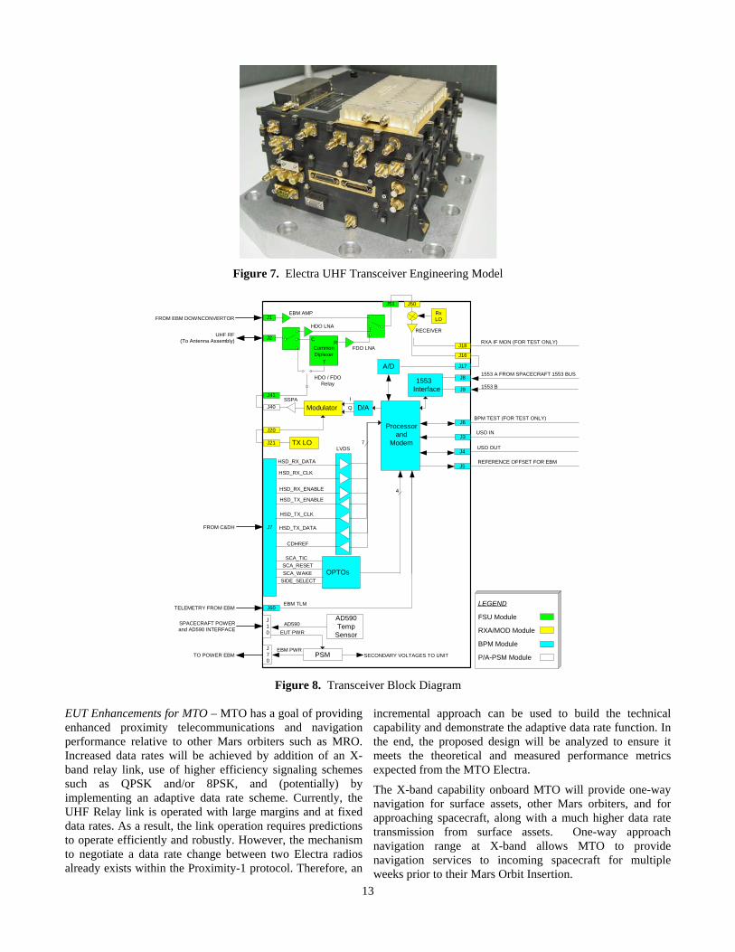
Figure 7. Electra UHF Transceiver Engineering Model
J1EBM AMP
J2
HDO LNA
FDO LNACommonDiplexer
J41
J40 Modulator D/A
J51 J50
J16
J17A/D
Processorand
Modem
J8
J91553
Interface
HDO / FDORelay
I
QSSPA
J20
J21 TX LO
J6
J3
BPM TEST (FOR TEST ONLY)
USO IN
1553 A FROM SPACECRAFT 1553 BUS
1553 B
J18RXA IF MON (FOR TEST ONLY)
RECEIVER
LVDS
HSD_RX_DATA
HSD_RX_CLK
HSD_RX_ENABLE
HSD_TX_DATA
HSD_TX_CLK
HSD_TX_ENABLE
OPTOs
SCA_TICSCA_RESETSCA_WAKE
SIDE_SELECT
4
J60EBM TLM
J10
J70
AD590Temp
Sensor
PSM
AD590EUT PWR
EBM PWR
J7
7
CDHREF
J4
J5
USO OUT
REFERENCE OFFSET FOR EBM
RxLOFROM EBM DOWNCONVERTOR
UHF RF(To Antenna Assembly)
FROM C&DH
TELEMETRY FROM EBM
SPACECRAFT POWERand AD590 INTERFACE
TO POWER EBM SECONDARY VOLTAGES TO UNIT
LEGEND
FSU Module
RXA/MOD Module
BPM Module
P/A-PSM Module
C R
T
Figure 8. Transceiver Block Diagram
EUT Enhancements for MTO – MTO has a goal of providing enhanced proximity telecommunications and navigation performance relative to other Mars orbiters such as MRO. Increased data rates will be achieved by addition of an X-band relay link, use of higher efficiency signaling schemes such as QPSK and/or 8PSK, and (potentially) by implementing an adaptive data rate scheme. Currently, the UHF Relay link is operated with large margins and at fixed data rates. As a result, the link operation requires predictions to operate efficiently and robustly. However, the mechanism to negotiate a data rate change between two Electra radios already exists within the Proximity-1 protocol. Therefore, an
incremental approach can be used to build the technical capability and demonstrate the adaptive data rate function. In the end, the proposed design will be analyzed to ensure it meets the theoretical and measured performance metrics expected from the MTO Electra.
The X-band capability onboard MTO will provide one-way navigation for surface assets, other Mars orbiters, and for approaching spacecraft, along with a much higher data rate transmission from surface assets. One-way approach navigation range at X-band allows MTO to provide navigation services to incoming spacecraft for multiple weeks prior to their Mars Orbit Insertion.
13

Electra hardware changes needed to support MTO requirements include development of an X-band downconverter to interface with the EUT. The downconverter will enable the EUT to accept an X-band signal (8400 – 8450 MHz) on a switchable secondary receive channel (SRC) and downconvert to UHF, which will then be processed by the EUT in the usual manner. Internal part changes included replacement of the smaller, 1M Gate Xilinx for the larger, 3M Gate version, to accommodate future expansion capability, such as a secondary receive channel for simultaneous asset tracking. The addition of core memory in the new Xilinx, internal to the UHF portion, allows for future software uploads that could enable a secondary receive channel, as well as superior signaling schemes that may yet to be developed. Providing sufficient I/O for future use has been deemed a necessary “improvement” to the unit to accommodate what may lie ahead in the next 10-15 years. In addition, to meet the MTO 10-year mission life requirement upscreening and/or substitution of specific EEE components, beyond parts swapped out for increased capability, has been necessary.
Lastly, MTO relay performance improvements will be achieved through the use of steerable medium gain UHF and X-band relay antennas having approximately 12-15 dBi and 30dBi of gain, respectively. Studies are currently in process to determine the best design to match MTO’s requirements.
6. LASER COMMUNICATIONS DEMO
Introduction
NASA’s Goddard Space Flight Center (GSFC), the Jet Propulsion Laboratory (JPL) of California Institute of Technology, and the Massachusetts Institute of Technology Lincoln Laboratory (MIT/LL) are working together on the Mars Laser Communication Demonstration (MLCD). GSFC is the lead for project management. JPL is providing the Principal Investigator and is lead for ground terminal development and operations. MIT/LL is the lead for the Mars Lasercom Terminal development and systems engineering. The Project will demonstrate high-rate optical communications from Mars and gain the knowledge and experience base that will enable NASA to design, procure, and operate cost-effective future deep space optical communication systems. This project is independent of the MTO relay functions and is intended only as a technology demonstration. The major components of MLCD are shown in Figure 9.
Figure 9. Mars Laser Communication Demonstration Block
Diagram
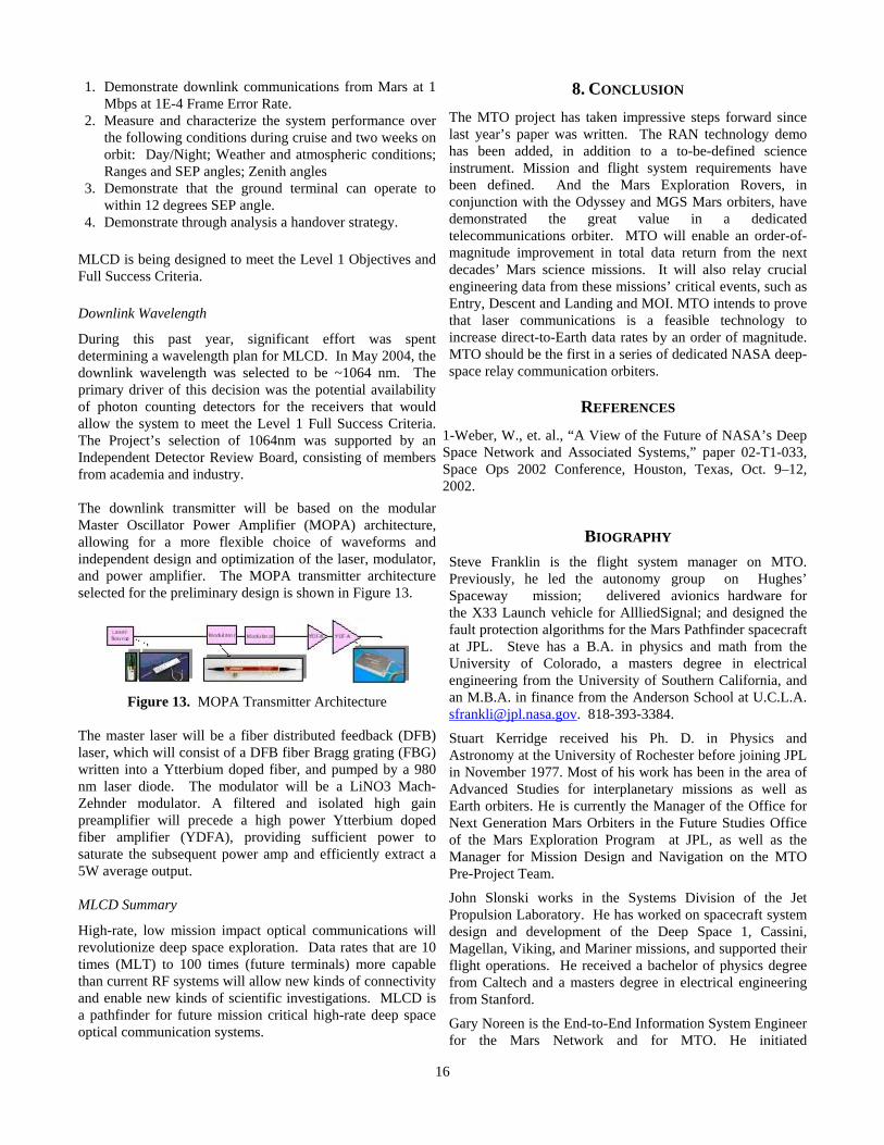
The Mars Lasercom Terminal (MLT) is the optical communications package that will fly to Mars on MTO. It consists of a 30-cm telescope that is carried on passive vibration-isolation struts. These both soften the vibrations during launch and reduce the in-space micro-vibrations that are present on the spacecraft during operation. Further beam stabilization is performed with a three-phase approach. The highest frequency stabilization is achieved by employing a high-speed tracking loop based on a fast steering mirror and a quad detector that monitors a pseudo-star, created by an on-board inertially-stabilized reference called a MIRU (Magnetohydrodynamic (MHD) Inertial Reference Unit.) Mid-frequency stabilization is performed by monitoring the bright image of the Earth on a focal plane array (FPA) and using the tracking error signal to re-center the MIRU, which has a low-frequency limit on its stability. Finally, a beacon signal, uplinked from either the Optical Communications Telescope Laboratory (OCTL) Transmit Terminal at Table Mountain, Ca., or the transportable Link Development and Evaluation System (LDES) Transmit Terminal, is also monitored on the FPA for absolute pointing measurements down to a small fraction of the beamwidth. A low rate uplink command channel will also be provided by both optical uplinks. A block diagram of the MLT configuration is shown in Figure 10.
14
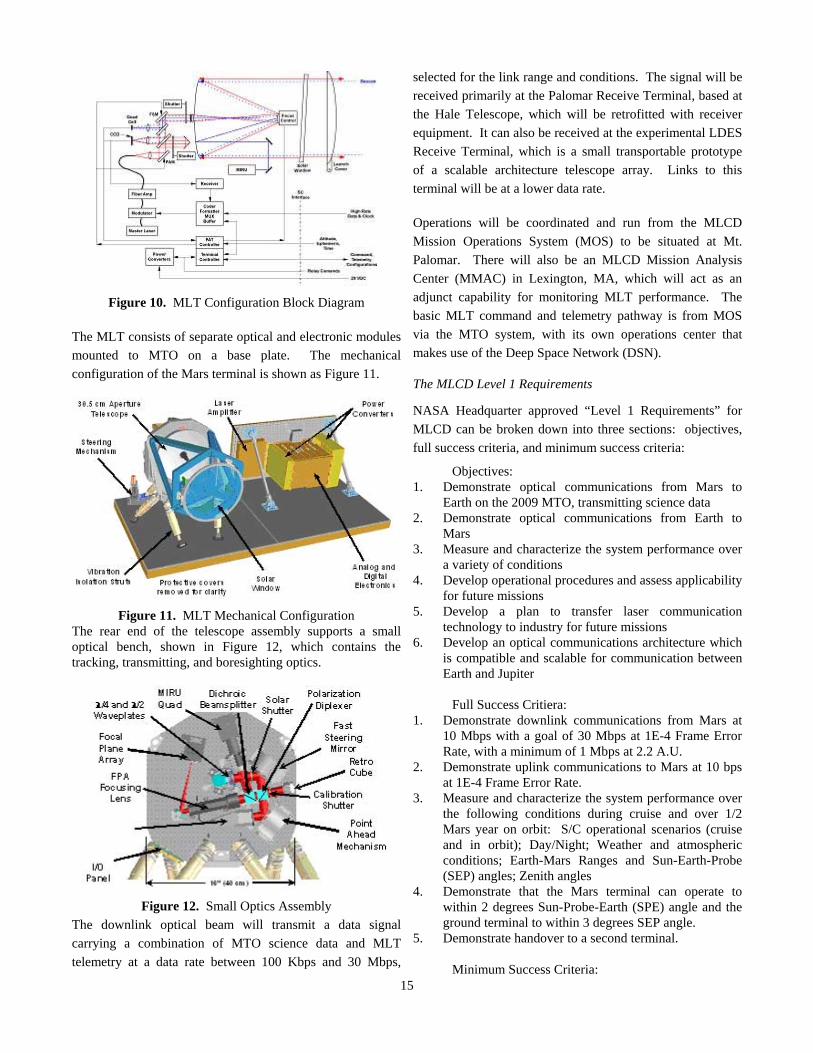
Figure 10. MLT Configuration Block Diagram
The MLT consists of separate optical and electronic modules mounted to MTO on a base plate. The mechanical configuration of the Mars terminal is shown as Figure 11.
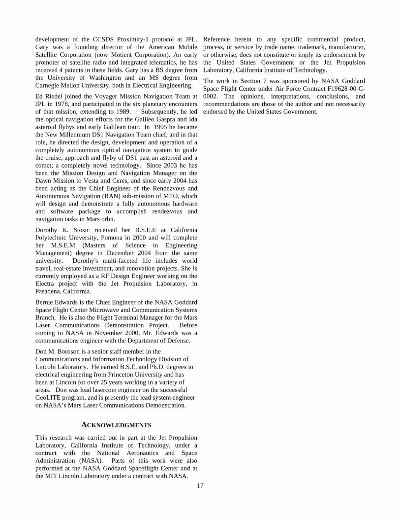
Figure 11. MLT Mechanical Configuration
The rear end of the telescope assembly supports a small optical bench, shown in Figure 12, which contains the tracking, transmitting, and boresighting optics.
Figure 12. Small Optics Assembly
The downlink optical beam will transmit a data signal carrying a combination of MTO science data and MLT telemetry at a data rate between 100 Kbps and 30 Mbps,
selected for the link range and conditions. The signal will be received primarily at the Palomar Receive Terminal, based at the Hale Telescope, which will be retrofitted with receiver equipment. It can also be received at the experimental LDES Receive Terminal, which is a small transportable prototype of a scalable architecture telescope array. Links to this terminal will be at a lower data rate. Operations will be coordinated and run from the MLCD Mission Operations System (MOS) to be situated at Mt. Palomar. There will also be an MLCD Mission Analysis Center (MMAC) in Lexington, MA, which will act as an adjunct capability for monitoring MLT performance. The basic MLT command and telemetry pathway is from MOS via the MTO system, with its own operations center that makes use of the Deep Space Network (DSN). The MLCD Level 1 Requirements
NASA Headquarter approved “Level 1 Requirements” for MLCD can be broken down into three sections: objectives, full success criteria, and minimum success criteria:
Objectives: 1. Demonstrate optical communications from Mars to
Earth on the 2009 MTO, transmitting science data 2. Demonstrate optical communications from Earth to
Mars 3. Measure and characterize the system performance over
a variety of conditions 4. Develop operational procedures and assess applicability
for future missions 5. Develop a plan to transfer laser communication
technology to industry for future missions 6. Develop an optical communications architecture which
is compatible and scalable for communication between Earth and Jupiter
Full Success Critiera: 1. Demonstrate downlink communications from Mars at
10 Mbps with a goal of 30 Mbps at 1E-4 Frame Error Rate, with a minimum of 1 Mbps at 2.2 A.U.
2. Demonstrate uplink communications to Mars at 10 bps at 1E-4 Frame Error Rate.
3. Measure and characterize the system performance over the following conditions during cruise and over 1/2 Mars year on orbit: S/C operational scenarios (cruise and in orbit); Day/Night; Weather and atmospheric conditions; Earth-Mars Ranges and Sun-Earth-Probe (SEP) angles; Zenith angles
4. Demonstrate that the Mars terminal can operate to within 2 degrees Sun-Probe-Earth (SPE) angle and the ground terminal to within 3 degrees SEP angle.
5. Demonstrate handover to a second terminal.
Minimum Success Criteria: 15
1. Demonstrate downlink communications from Mars at 1 Mbps at 1E-4 Frame Error Rate.
2. Measure and characterize the system performance over the following conditions during cruise and two weeks on orbit: Day/Night; Weather and atmospheric conditions; Ranges and SEP angles; Zenith angles
3. Demonstrate that the ground terminal can operate to within 12 degrees SEP angle.
4. Demonstrate through analysis a handover strategy.
MLCD is being designed to meet the Level 1 Objectives and Full Success Criteria. Downlink Wavelength
During this past year, significant effort was spent determining a wavelength plan for MLCD. In May 2004, the downlink wavelength was selected to be ~1064 nm. The primary driver of this decision was the potential availability of photon counting detectors for the receivers that would allow the system to meet the Level 1 Full Success Criteria. The Project’s selection of 1064nm was supported by an Independent Detector Review Board, consisting of members from academia and industry. The downlink transmitter will be based on the modular Master Oscillator Power Amplifier (MOPA) architecture, allowing for a more flexible choice of waveforms and independent design and optimization of the laser, modulator, and power amplifier. The MOPA transmitter architecture selected for the preliminary design is shown in Figure 13.
Figure 13. MOPA Transmitter Architecture
The master laser will be a fiber distributed feedback (DFB) laser, which will consist of a DFB fiber Bragg grating (FBG) written into a Ytterbium doped fiber, and pumped by a 980 nm laser diode. The modulator will be a LiNO3 Mach-Zehnder modulator. A filtered and isolated high gain preamplifier will precede a high power Ytterbium doped fiber amplifier (YDFA), providing sufficient power to saturate the subsequent power amp and efficiently extract a 5W average output. MLCD Summary
High-rate, low mission impact optical communications will revolutionize deep space exploration. Data rates that are 10 times (MLT) to 100 times (future terminals) more capable than current RF systems will allow new kinds of connectivity and enable new kinds of scientific investigations. MLCD is a pathfinder for future mission critical high-rate deep space optical communication systems.
8. CONCLUSION The MTO project has taken impressive steps forward since last year’s paper was written. The RAN technology demo has been added, in addition to a to-be-defined science instrument. Mission and flight system requirements have been defined. And the Mars Exploration Rovers, in conjunction with the Odyssey and MGS Mars orbiters, have demonstrated the great value in a dedicated telecommunications orbiter. MTO will enable an order-of-magnitude improvement in total data return from the next decades’ Mars science missions. It will also relay crucial engineering data from these missions’ critical events, such as Entry, Descent and Landing and MOI. MTO intends to prove that laser communications is a feasible technology to increase direct-to-Earth data rates by an order of magnitude. MTO should be the first in a series of dedicated NASA deep-space relay communication orbiters.
REFERENCES 1-Weber, W., et. al., “A View of the Future of NASA’s Deep Space Network and Associated Systems,” paper 02-T1-033, Space Ops 2002 Conference, Houston, Texas, Oct. 9–12, 2002.
BIOGRAPHY Steve Franklin is the flight system manager on MTO. Previously, he led the autonomy group on Hughes’ Spaceway mission; delivered avionics hardware for the X33 Launch vehicle for AllliedSignal; and designed the fault protection algorithms for the Mars Pathfinder spacecraft at JPL. Steve has a B.A. in physics and math from the University of Colorado, a masters degree in electrical engineering from the University of Southern California, and an M.B.A. in finance from the Anderson School at U.C.L.A. [email protected]. 818-393-3384.
Stuart Kerridge received his Ph. D. in Physics and Astronomy at the University of Rochester before joining JPL in November 1977. Most of his work has been in the area of Advanced Studies for interplanetary missions as well as Earth orbiters. He is currently the Manager of the Office for Next Generation Mars Orbiters in the Future Studies Office of the Mars Exploration Program at JPL, as well as the Manager for Mission Design and Navigation on the MTO Pre-Project Team.
John Slonski works in the Systems Division of the Jet Propulsion Laboratory. He has worked on spacecraft system design and development of the Deep Space 1, Cassini, Magellan, Viking, and Mariner missions, and supported their flight operations. He received a bachelor of physics degree from Caltech and a masters degree in electrical engineering from Stanford.
Gary Noreen is the End-to-End Information System Engineer for the Mars Network and for MTO. He initiated
16
17
development of the CCSDS Proximity-1 protocol at JPL. Gary was a founding director of the American Mobile Satellite Corporation (now Motient Corporation). An early promoter of satellite radio and integrated telematics, he has received 4 patents in these fields. Gary has a BS degree from the University of Washington and an MS degree from Carnegie Mellon University, both in Electrical Engineering.
Ed Riedel joined the Voyager Mission Navigation Team at JPL in 1978, and participated in the six planetary encounters of that mission, extending to 1989. Subsequently, he led the optical navigation efforts for the Galileo Gaspra and Ida asteroid flybys and early Galilean tour. In 1995 he became the New Millennium DS1 Navigation Team chief, and in that role, he directed the design, development and operation of a completely autonomous optical navigation system to guide the cruise, approach and flyby of DS1 past an asteroid and a comet; a completely novel technology. Since 2003 he has been the Mission Design and Navigation Manager on the Dawn Mission to Vesta and Ceres, and since early 2004 has been acting as the Chief Engineer of the Rendezvous and Autonomous Navigation (RAN) sub-mission of MTO, which will design and demonstrate a fully autonomous hardware and software package to accomplish rendezvous and navigation tasks in Mars orbit.
Dorothy K. Stosic received her B.S.E.E at California Polytechnic University, Pomona in 2000 and will complete her M.S.E.M (Masters of Science in Engineering Management) degree in December 2004 from the same university. Dorothy's multi-faceted life includes world travel, real-estate investment, and renovation projects. She is currently employed as a RF Design Engineer working on the Electra project with the Jet Propulsion Laboratory, in Pasadena, California.
Bernie Edwards is the Chief Engineer of the NASA Goddard Space Flight Center Microwave and Communication Systems Branch. He is also the Flight Terminal Manager for the Mars Laser Communications Demonstration Project. Before coming to NASA in November 2000, Mr. Edwards was a communications engineer with the Department of Defense.
Don M. Boroson is a senior staff member in the Communications and Information Technology Division of Lincoln Laboratory. He earned B.S.E. and Ph.D. degrees in electrical engineering from Princeton University and has been at Lincoln for over 25 years working in a variety of areas. Don was lead lasercom engineer on the successful GeoLITE program, and is presently the lead system engineer on NASA’s Mars Laser Communications Demonstration.
ACKNOWLEDGMENTS This research was carried out in part at the Jet Propulsion Laboratory, California Institute of Technology, under a contract with the National Aeronautics and Space Administration (NASA). Parts of this work were also performed at the NASA Goddard Spaceflight Center and at the MIT Lincoln Laboratory under a contract with NASA.
Reference herein to any specific commercial product, process, or service by trade name, trademark, manufacturer, or otherwise, does not constitute or imply its endorsement by the United States Government or the Jet Propulsion Laboratory, California Institute of Technology.
The work in Section 7 was sponsored by NASA Goddard Space Flight Center under Air Force Contract F19628-00-C-0002. The opinions, interpretations, conclusions, and recommendations are those of the author and not necessarily endorsed by the United States Government.