testing grid application workflows using ttcn-3
TRANSCRIPT

Testing Grid Application Workflows Using TTCN-3
Thomas Rings, Helmut Neukirchen, Jens GrabowskiSoftware Engineering for Distributed Systems Group,
Institute for Computer Science, University of Gottingen,Lotzestr. 16–18, 37083 Gottingen, Germany.
{rings,neukirchen,grabowski}@cs.uni-goettingen.de
Abstract
The collective and coordinated usage of distributed re-sources for problem solution within dynamic virtual orga-nizations can be realized with the Grid computing technol-ogy. For distributing and solving a task, a Grid applicationinvolves a complex workflow of dividing a task into smallersub-tasks, scheduling and submitting jobs for solving thosesub-tasks, and eventually collecting and combining the re-sults of the sub-tasks into a final result. The quality assur-ance of Grid applications is a challenge due to the highlydistributed nature of the Grid environment in which the Gridapplication is deployed. This paper investigates the appli-cability of the Testing and Test Control Notation (TTCN-3)for testing the workflows of distributed Grid applications.To this aim, a case study has been created that consistsof a distributed Grid application which includes a typicalGrid application workflow; as the main contribution, thiscase study contains a corresponding distributed TTCN-3test suite that tests the correct execution of the Grid appli-cation workflow. To demonstrate the adaptation of the ab-stract TTCN-3 test suite to a specific Grid environment, cor-responding reusable test adapters have been implementedfor the Grid middleware Globus Toolkit 4 (GT4). The real-ized test system demonstrates that TTCN-3 is applicable fortesting the workflow of distributed Grid applications.
1. Introduction
In the last years, supercomputing experienced a change:expensive super computer hardware is replaced by cheaperdistributed computer Grids. This trend has manifold rea-sons: on the one hand, today’s demand for super comput-ing resources grows faster than Moore’s law and can thusonly be satisfied using distributed computing; on the otherhand processor cycles from idling computers can be cost-efficiently scavenged using Grid technology. Finally, Gridcomputing offers the promise to make computing, as well
as, access to data and remote equipment as easy as the useof electricity from the electrical power grid. Like in manyother domains, this trend is accompanied with the problemthat the corresponding software becomes more complex andtheir development more error-prone. Surprisingly, qualityassurance for Grid computing software is not very matureand only a few proprietary test approaches exist. This paperinvestigates the applicability of the standardized Testing andTest Control Notation (TTCN-3) for testing in Grid envi-ronments. While testing of Grid middleware is comparableto message-based protocol testing using the ConformanceTesting Methodology and Framework (CTMF) standard, wefocus on functional testing of distributed Grid applicationsthat make use of higher-level communication mechanisms.
This paper is structured as follows: In Section 2, we givean overview about the foundations of Grid computing, con-formance testing, and TTCN-3. Afterwards, in Section 3,we describe the Grid application used in this paper. In Sec-tion 4, we focus on the TTCN-3 case study that is used totest the Grid application introduced in Section 3. In Sec-tion 5, we provide a comparison with related work. Finally,we conclude with a summary and outlook in Section 6.
2. Foundations
In the following, we provide a brief overview on Gridcomputing, on the Conformance Testing Methodology andFramework (CTMF) that we adopt for distributed functionaltesting, and on the test language TTCN-3 that we apply forthe specification and implementation of our tests.
2.1. Grid computing
For performing resource intensive and complex tasks,a Grid computing environment provides an efficient shar-ing and management of computing resources [2], whichare not administered centrally, in order to achieve a non-trivial quality of service [6]. To overcome the high de-gree of heterogeneity of the underlying resources, a Grid
2008 International Conference on Software Testing, Verification, and Validation
0-7695-3127-X/08 $25.00 © 2008 IEEEDOI 10.1109/ICST.2008.24
210
2008 International Conference on Software Testing, Verification, and Validation
0-7695-3127-X/08 $25.00 © 2008 IEEEDOI 10.1109/ICST.2008.24
210
2008 International Conference on Software Testing, Verification, and Validation
0-7695-3127-X/08 $25.00 © 2008 IEEEDOI 10.1109/ICST.2008.24
210
2008 International Conference on Software Testing, Verification, and Validation
978-0-7695-3127-4/08 $25.00 © 2008 IEEEDOI 10.1109/ICST.2008.24
210

computing environment uses open, standard, general pur-pose protocols and interfaces as middleware. Particularly,a standardization of Grid computing allows a dynamic ne-gotiation and management of shared resources between anyinterested parties of a virtual organization [6].
The architecture of a Grid system can be described interms of layers as depicted in Figure 1. The lowest layer,the Fabric layer, provides a basis as a common interface forall kinds of physical devices or resources that can includecomputers, networks, and storage systems [5, 8].
The Connectivity layer is located above the Fabric layerand defines the core communication and authentication pro-tocols, which are required by the Grid. The delegation ofauthorizations and methods for a single sign-on are essen-tial for this layer [5, 8].
In the Resource layer, which is above the Connectivitylayer, the common access to several resources is organizedin order to enable secure initiation, monitoring, and controlof resource-sharing operations, such as assignment or reser-vation [5, 8].
The role of the Collective layer that is above the Re-source layer is the coordination between different resources.Responsibilities of the Collective layer include directoryand brokering services for discovery, allocation, monitor-ing, and diagnostic of resources [5, 8].
At the top of any Grid system is the Application layerwith the user applications. These make use of the servicesprovided by the lower layers that allow to access resourcestransparently [8].
The algorithm of an application that is supposed to runin a Grid computing environment should be parallelizable totap the full potential of the advantages of Grid computing,i.e., the main task is divided into smaller sub-tasks in orderto allow parallel computation. Hence, a Grid application ispartitioned into independently running sub-applications.
The usual approach for creating a Grid application is tosolve each sub-task by a sub-application, i.e., an executableprogram. A node of the Grid, on which that sub-applicationis installed, may then execute that sub-application as a job.It is very common that an already existing command-lineapplication shall be integrated into a Grid (“gridification”).As long as the already existing command-line applicationcan be requested by the appropriate parameters to solve notthe whole problem, but only a part of the problem, thiscommand-line application can be integrated without anychanges as sub-application. Since the existing command-line applications write in most cases their output into a file,this file can than be transferred via a network file transferservice between the different nodes of the Grid as required.
To control the workflow of dividing a task into smallersub-tasks, scheduling and submitting jobs for solving thosesub-tasks, monitoring the execution of the jobs, and even-tually collecting and combining the results of the sub-tasks
Figure 1. Layered Grid architecture mappedwith the Internet protocol architecture [8]
into a final result, a separate application management is re-quired. This application management provides an interfaceto the Grid user and thus hides the complexity of the under-lying Grid technology.
It depends on the services that are actually provided bythe layers of a Grid middleware implementation, which ofthe above steps actually need to be implemented by theapplication management or whether the application man-agement may delegate them to a lower layer. If, for ex-ample, a Grid environment offers a full-fledged Collectivelayer, the application management may rely on workflowmanagement services from that layer. If, for example, aGrid environment offers only minimal services in its lay-ers and thus lacks scheduling, software discovery and bro-kering services, the application management may even beresponsible for assigning and submitting its jobs to appro-priate nodes of the Grid.
The application management and the related sub-applications form a massively distributed application.While the Grid middleware itself may use fine-grainedmessage- or procedure-based communication mechanisms,a Grid application uses coarse-grained communicationmechanisms, namely remote job submission and remote filetransfer. Thus it is investigated in the remainder of this pa-per whether known distributed testing methods and tech-nologies apply for testing Grid applications as well.
In the case that the sub-applications of a Grid applicationare existing command-line applications, it can be assumedthat these applications are already adequately tested. How-ever, the application management of a Grid application hasusually been developed from scratch and thus requires thor-ough testing.
2.2. Conformance Testing Methodology andFramework
For the functional black-box testing of distributedGrid applications, we adopt concepts of the internationalISO/IEC multipart standard 9646 OSI Conformance TestingMethodology and Framework (CTMF) [13]. CTMF definesa comprehensive procedure for the conformance testing of
211211211211

Open Systems Interconnection (OSI) protocol implementa-tions. The entire standard consists of seven parts and coversthe following aspects: concepts (Part 1), test suite specifi-cation and test system architectures (Part 2), test notation(Part 3), test realization (Part 4), means of testing, and or-ganizational aspects (parts 5–7).
Even though CTMF provides concepts and means thatare specific to OSI protocol testing, CTMF has been suc-cessfully applied for testing other kinds of distributed sys-tems like for example, ISDN- and GSM-based systems.Thus, we decided to adopt concepts from CTMF as wellfor functional testing of distributed Grid applications. How-ever, only the test suite production procedures and test ar-chitecture from Part 2 of CTMF were applicable for ourwork, because the other parts were too OSI or conformancetesting specific.
The CTMF procedure for producing test suites startswith the identification of the requirements to be tested. Therequirements are used to define test groups necessary toachieve an appropriate coverage of the requirements. Theobjective of each test group is described by means of an in-formal test objective. For each test group, a set of test pur-poses is developed. A test purpose is an informal or semi-formal description of a test case. Afterwards, an appropriatetest architecture is selected and for each test purpose, a testcase is implemented by means of a test language.
The CTMF test methods are abstract, i.e., implemen-tation independent, test architectures. They define Imple-mentation Under Test (IUT), System Under Test (SUT), thePoints of Control and Observation (PCOs) that are neededto control and observe the SUT, and the connections be-tween these constituents.
Figure 2 presents the CTMF Multi-party test method,which we used to test the application management. TheIUT is controlled and observed by one Upper Tester (UT)and several Lower Testers (LTs). The underlying serviceand the IUT constitute the SUT. CTMF assumes a layeredarchitecture: the LTs communicate with the IUT by using anunderlying communication service. It is assumed that thisservice provider has already been adequately tested. Con-ceptually, the UT plays the role of a service user of the IUTand LTs play the role of peer entities that realize togetherwith the IUT the service used by the UT. The PCOs are thestandardized interfaces used by UT and LTs to communi-cate with the SUT. UT and LTs communicate by means ofTest Coordination Procedures (TCPs). To avoid probe ef-fects, the underlying communication service should not beused for the implementation of the TCPs.
For the functional testing of Grid applications, we fol-lowed Part 2 of CTMF to produce test suites and adaptedthe standardized test methods to the Grid requirements. Aspart of this adaption, we do not distinguish between UT andLT, but use the more general term test component instead.
Figure 2. CTMF Multi-party test method
2.3. TTCN-3
The Testing and Test Control Notation (TTCN-3) [4, 11]is a test specification and test implementation languagestandardized by the European Telecommunications Stan-dards Institute (ETSI) and the International Telecommuni-cation Union (ITU). While TTCN-3 has its roots in func-tional black-box testing of telecommunication systems, itis nowadays also used in other domains such as Internetprotocols, automotive, aerospace, or service-oriented archi-tectures. TTCN-3 can be used not only for specifying andimplementing functional tests, but also for scalability, ro-bustness, or stress tests.
The TTCN-3 language has the look and feel of a typicalgeneral purpose programming language, i.e., it is based ona textual syntax. Most of the concepts of general purposeprogramming languages can be found in TTCN-3 as well,e.g. data types, variables, functions, parameters, loops, con-ditional statements, and import mechanisms. In addition,test related concepts are available to ease the specificationof test suites.
TTCN-3 supports distributed testing through the notionof test components: in addition to the Main Test Compo-nent (MTC), Parallel Test Components (PTCs) can be cre-ated dynamically. Each test component runs concurrentlyand may therefore execute test behavior in parallel to othertest components. Test components can be connected to eachother or to the SUT via ports. These concepts allow to cre-ate powerful distributed test architectures, for example in-stantiations of the CTMF test methods.
For the communication between test components andwith the SUT, operation such as send and receive (TTCN-3keywords are printed in bold typeface) can be used to trans-fer messages via ports. The values of these message arespecified using templates. TTCN-3 templates may involvewildcards and thus provide a powerful matching mechanismto check whether expected test data has been received ornot.
Further concepts that ease test specification are: test ver-dict handling, logging, timers, and defaults. Defaults aretypically used for specifying alternative behavior that deals
212212212212

with unexpected events. Since a receive operation blocksuntil it observes a message that matches the specified tem-plate, defaults can be activated to catch, e.g. the expirationof a timer or any unexpected message.
To allow the automated execution of TTCN-3 test suites,TTCN-3 tools can be used to compile TTCN-3 test specifi-cations into executable tests. However, TTCN-3 test spec-ifications use abstract communication mechanisms. Thus,to make TTCN-3 test specifications executable, an adap-tation layer is required. Hence, a System Adapter (SA)entity that implements operations of the TTCN-3 RuntimeInterface (TRI) [4] and a Coding/Decoding (CD) entitythat implements operations of the TTCN-3 Control Inter-face (TCI) [4, 18] must be additionally realized.
For those ports that are mapped to PCOs, the SA realizessend and receive operations by using the communicationmechanisms of the SUT, e.g. sockets. The CD is responsi-ble for the translation between the abstract TTCN-3 valuesand the concrete bit-level data encoding used by the SUT.
Using TTCN-3 has several advantages in comparison toproprietary test languages or low-level test implementation.The high abstraction level speeds up test development. Fur-thermore, the re-usability is higher, because both, the ab-stract TTCN-3 test specifications and the adapters, can bere-used independently from each other. Finally, due to thefact that TTCN-3 is standardized and various TTCN-3 toolsare available, a vendor dependence is avoided.
3. Grid application
For investigating the applicability of TTCN-3 for test-ing the workflow of Grid applications, we developed a Gridapplication that consists of an application management andcorresponding calculation sub-applications.
The application that is transferred into a Grid applica-tion solves the task of calculating the Mandelbrot set [15]or a subset, respectively. This task is parallelizable, be-cause each element of the Mandelbrot set can be calcu-lated independently from each other. A corresponding non-interactive Mandelbrot set Calculation Application has beenimplemented: it uses command-line parameters that specifyas input the subset of the Mandelbrot set that shall be cal-culated and provides as output a file that contains a colorgraphic of the calculated Mandelbrot subset.
For the gridification of this application, an ApplicationManagement and the actual Calculation Application haveto be integrated into the Grid environment. To ensure thatwe are able to investigate also the case, where a Grid envi-ronment does not provide services of the higher Grid layers,the Application Management realizes on its own services ofthe Collective layer such as job scheduling and assigningjobs to the nodes of the Grid.
Grid Middleware: Globus Toolkit 4 (GT4), Network File System (NFS)
ApplicationManagement
CalculationApplication
CalculationApplication … Calculation
Application
User interaction
Master node Node 1 Node 2 Node n…
Figure 3. Application integration into the Gridenvironment
3.1. The Grid environment
The Grid environment that has been applied for hostingthe implemented Grid application is the Instant-Grid [12]environment that is a project funded by the e-Science Ini-tiative from the German Federal Ministry of Education andResearch. Instant-Grid provides a complete computer Gridenvironment based on a Knoppix [14] Linux live CD-ROM,which includes all required services for establishing a Gridwith Intel x86 computers. It includes an automated con-figuration mechanism that deploys without any user inter-action Instant-Grid on computers that share a Local AreaNetwork (LAN).
Instant-Grid uses the software services and librariesoffered by the Globus Toolkit 4 (GT4) Grid middle-ware [7, 10] that is developed by the Globus Alliance. GT4implements the Resource and Connectivity layers of theGrid protocol architecture. The higher Collective and Ap-plication layers are not provided by GT4, but by Instant-Grid and its user applications.
Additional to these services, Instant-Grid offers a Net-work File System (NFS) for collective data access by allnodes of the Grid. Alternatively, it is possible to use theGT4 GridFTP service for data transfer.
3.2. Integration into the Grid
The integration of the Mandelbrot set Calculation Appli-cation and its Application Management into Instant-Grid isdepicted in Figure 3. It has been integrated as a Grid ap-plication into the Instant-Grid CD-ROM in order to make itavailable on the file system of each Grid node.
After the user has sent a request, the Application Man-agement divides this request into sub-tasks and submitsthem as jobs to GT4 in order to execute the Calculation Ap-plication on an idle node. For the submission of a job, theGT4 service globusrun-ws is used. This call requires asparameters the name of a node, the name of the executableto be started, its file system location, and command-line pa-rameters.
213213213213
7. compose job result
6. submit compose job
1. start calculation
2. submit job
3. submit job
4. job result
5. job result
Master node Node 1 Node 2
8. composed result
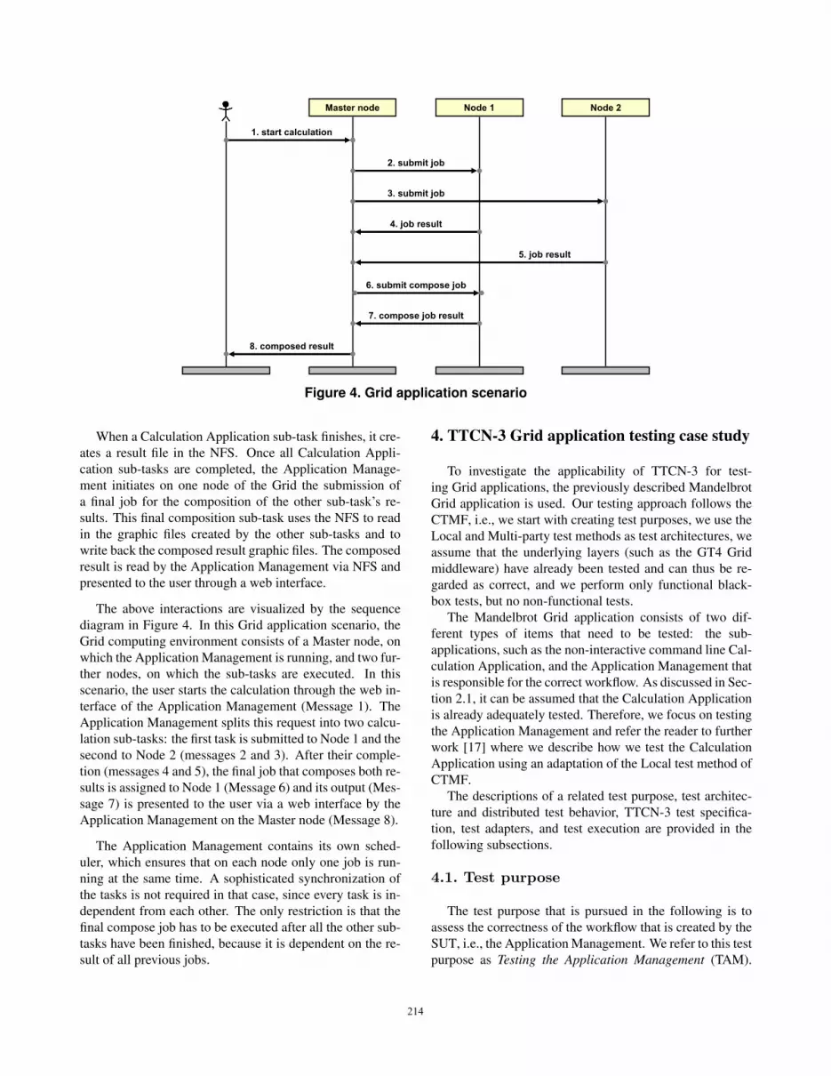
Figure 4. Grid application scenario
When a Calculation Application sub-task finishes, it cre-ates a result file in the NFS. Once all Calculation Appli-cation sub-tasks are completed, the Application Manage-ment initiates on one node of the Grid the submission ofa final job for the composition of the other sub-task’s re-sults. This final composition sub-task uses the NFS to readin the graphic files created by the other sub-tasks and towrite back the composed result graphic files. The composedresult is read by the Application Management via NFS andpresented to the user through a web interface.
The above interactions are visualized by the sequencediagram in Figure 4. In this Grid application scenario, theGrid computing environment consists of a Master node, onwhich the Application Management is running, and two fur-ther nodes, on which the sub-tasks are executed. In thisscenario, the user starts the calculation through the web in-terface of the Application Management (Message 1). TheApplication Management splits this request into two calcu-lation sub-tasks: the first task is submitted to Node 1 and thesecond to Node 2 (messages 2 and 3). After their comple-tion (messages 4 and 5), the final job that composes both re-sults is assigned to Node 1 (Message 6) and its output (Mes-sage 7) is presented to the user via a web interface by theApplication Management on the Master node (Message 8).
The Application Management contains its own sched-uler, which ensures that on each node only one job is run-ning at the same time. A sophisticated synchronization ofthe tasks is not required in that case, since every task is in-dependent from each other. The only restriction is that thefinal compose job has to be executed after all the other sub-tasks have been finished, because it is dependent on the re-sult of all previous jobs.
4. TTCN-3 Grid application testing case study
To investigate the applicability of TTCN-3 for test-ing Grid applications, the previously described MandelbrotGrid application is used. Our testing approach follows theCTMF, i.e., we start with creating test purposes, we use theLocal and Multi-party test methods as test architectures, weassume that the underlying layers (such as the GT4 Gridmiddleware) have already been tested and can thus be re-garded as correct, and we perform only functional black-box tests, but no non-functional tests.
The Mandelbrot Grid application consists of two dif-ferent types of items that need to be tested: the sub-applications, such as the non-interactive command line Cal-culation Application, and the Application Management thatis responsible for the correct workflow. As discussed in Sec-tion 2.1, it can be assumed that the Calculation Applicationis already adequately tested. Therefore, we focus on testingthe Application Management and refer the reader to furtherwork [17] where we describe how we test the CalculationApplication using an adaptation of the Local test method ofCTMF.
The descriptions of a related test purpose, test architec-ture and distributed test behavior, TTCN-3 test specifica-tion, test adapters, and test execution are provided in thefollowing subsections.
4.1. Test purpose
The test purpose that is pursued in the following is toassess the correctness of the workflow that is created by theSUT, i.e., the Application Management. We refer to this testpurpose as Testing the Application Management (TAM).
214214214214

5. compose job result
1. start calculation
2. submit job
3. job result
SUT
6. composed result
Test System
loop[All jobs results received]
4. submit compose job
Figure 5. Test purpose TAM illustrated as asequence diagram
For testing the correctness of the workflow, the job submis-sion order and the parameters that are passed to the jobs bythe SUT have to be checked.
The message exchange of the TAM test purpose is basedon the Grid application scenario in Figure 4. In addition tomessages that relate to the actual job submission, the testpurpose includes also the start of the calculation via theWeb-based user interface as an initial stimulus and the pre-sentation of the final composed result to the user.
The corresponding graphical representation of the TAMtest purpose is depicted in the sequence diagram in Figure 5.Initially, the test system sends a message for stimulating theSUT (Message 1). This stimulus includes the data that issupposed to be entered by the user. The SUT uses this datain order to determine the parameters for the sub-tasks. Afterthis determination, the SUT assigns the tasks to the nodes ofthe Grid by submitting jobs via the Grid middleware. Thetest system has to observe these job submissions (includ-ing their parameters) to decide whether the SUT divided theoverall task correctly into sub-tasks (Message 2). Since theSUT expects that each job returns a file as result, the testsystem has to provide them to the SUT (Message 3). Thenumber of jobs that are submitted by the SUT depends onthe parameters that are passed in the stimulating start cal-culation message. Hence, the sequence diagram for the testpurpose TAM contains a loop that iterates until the expectednumber of job submissions has been observed by the testsystem. After the correct number of calculation sub-taskshas been performed, it has to be tested if the final compo-sition job has been submitted with the correct parameters(Message 4). Afterwards, the test system provides the over-all result as file to the SUT (Message 5). Finally, it is testedthat the SUT forwards this composed result correctly to theuser interface (Message 6).
Figure 6. Test architecture for test purposeTAM
4.2. Test architecture and distribution oftest behavior
To turn the TAM test purpose into a test case, a suitabletest architecture needs to be selected and the test behaviorneeds to be assigned to the different test components of thetest architecture. Because the job submissions that are per-formed by the SUT may result in the execution of processeson nodes that are distributed throughout the Grid, the Multi-party test method of CTMF is a suitable test architecture.Thus, the SUT comprises not only the Application Man-agement that is actually the IUT but also the lower layers ofthe Grid middleware.
Figure 6 shows the test architecture that is used for test-ing the TAM test purpose. This figure is related to Figure 3and shows the integration of the test system into the Grid en-vironment: the human user is substituted by the Main TestComponent (MTC), i.e., the MTC stimulates the IUT viaan HTTP-based interface and observes the final composedresult. For observing that the IUT submits jobs correctly tothe nodes of the Grid environment, a Parallel Test Compo-nent (PTC) is required on each node. These PTCs serve asstubs for the Calculation Application and are thus able tointercept the parameters of the job submission. Since thesePTCs replace the Calculation Application, they must alsobe able to provide a file as job result. The same considera-tions apply for the final compose job sub-application that isreplaced as well by a stub.
It is not possible to predict to which node the schedulerinside the IUT submits a job. This may depend on the cur-rent load in the Grid and on differing computing power ofthe nodes. Hence, in every test run, different nodes may beselected by the IUT. Therefore, a PTC cannot decide usingits local knowledge only, whether observed job submissionsare part of a correct workflow or not. Instead, global knowl-edge is required to be able to decide whether for each sub-task a corresponding job has been submitted. To this aim,each PTC forwards the observed job submission parametersto the MTC, thus providing the MTC with global knowledgethat is required to set a test verdict. To support these test co-
215215215215

Listing 1. Excerpt of the TTCN-3 test behaviorfor test purpose TAM
1 ...2 // send the stimulus3 pt http .send(a httpStimulus(HORIZONTAL, VERTICAL, v workingpath));45 // check received job parameters messages6 while( i<HORIZONTAL∗VERTICAL) {7 pt PTCParameters.receive(8 a Reaction( ?, ?, ?, ?, ?, ?, ?, ?, ?, ?, ?))9 −> value v Parameters {
10 v check := false ;11 for ( j :=0; j<HORIZONTAL∗VERTICAL; j:=j+1) {12 // check if the received message is in the array13 if (v Parameters == JobArray[j]) {14 log( ”matched ReactionType”);15 checkArray[j] := true ;16 v check := true ;17 i := i+1;18 }19 }20 // if the message does not match, testcase failed21 if (v check == false) {22 log( ”mismatch”);23 setverdict ( fail );24 }25 }26 }27 ...
ordination procedures between the PTCs and the MTC, thetest architecture provides also the corresponding communi-cation channels (“test infrastructure” in Figure 6).
4.3. TTCN-3 test specification
The actual test suite for testing the Grid application isspecified using TTCN-3. It contains definitions of types,test data templates, several test components as well as testbehavior. The behavior of a TTCN-3 test case for the testpurpose TAM is described in the following. The test caseitself is parameterized to support a stimulation of the IUTwith different job sizes and to be able to specify the numberof nodes in the Grid environment, i.e. how many test com-ponents are to be created in order to observe all relevantnodes of the Grid.
The MTC is responsible for dynamically creating thePTCs of the distributed test architecture, connecting the testcomponents to each other, and starting the behavior on theseveral PTCs. Afterwards, the actual behavior that relatesto the test purpose TAM is performed. Listing 1 shows thecorresponding excerpt of the test case that runs on the MTC.
First, the MTC sends the stimulus to the SUT (Line 3in Listing 1). This corresponds to Message 1 in Figure 5.The data used for the stimulation is specified by the pa-rameterized TTCN-3 template a httpStimulus (Line 3 inListing 1). It includes the desired resolution of the finaloutput graphic and the file system working path, where theIUT places the output graphic. According to the applica-tion’s specification, the desired resolution of the final out-
put graphic influences directly the number of jobs that aresubmitted by the IUT. The actual parameter values for theparameterized template are based on test case parametersand can thus be easily changed to obtain test cases with dif-ferent test data.
The while loop in lines 6 to 26 is used collect the ob-served job parameter values that are forwarded by the PTCsto the MTC. Since the order, in which the forwarded jobssubmission messages are received, cannot be predicted, asort of tally sheet is used. All the expected job parametersare predefined and stored in the array JobArray – the pre-definition of this array is not shown in the excerpt. Once anarbitrary job submission message is received (the ? wild-cards in the template used in lines 7–8 matches any jobsubmission message), the contained jobs parameters are re-trieved and stored into the variable v Parameters (Line 9).The for loop in lines 11–19 checks whether the received jobparameters correspond to one of the predefined job param-eters from JobArray. If true, this is marked in the Booleanarray checkArray (Line 15). If false, the for loop will even-tually terminate unsuccessfully and the test verdict will beset to fail (Line 23). Subsequently (not shown in the ex-cerpt anymore), it is checked that no further job submissionsare received and that all jobs in the checkArray have beenmarked, i.e., all of the expected job submissions have beenobserved. All of the above described test behavior relates tohow the MTC implements the test coordination proceduresthat are associated to Message 2 in Figure 5.
Since a distributed test architecture is used, the PTCs ex-ecute behavior as well: once a Calculation Application jobsubmission is observed at a PTC (Message 2 in Figure 5),the job parameters are forwarded to the MTC as part ofthe associated test coordination procedures. After a con-figurable amount of time, the PTC creates a graphic file asresult (Message 3 in Figure 5).
The remainder of the TTCN-3 test case contains behav-ior that relates to messages 4–6 of the test purpose depictedin Figure 5. Furthermore, to prevent blocking in the casethat no message arrive and to be able to detect when un-expected messages are observed, the TTCN-3 concept ofdefaults is used: such a default is activated at the beginningof the test case and a timer is started. In case that the defaultcatches a timeout or a wrong message, the fail test verdictis automatically set by the behavior of the default.
4.4. Adaptation layer
The TTCN-3 test suite that has been described in the pre-vious subsection, abstracts from implementation details ofthe Grid middleware. Hence, to allow an automated execu-tion of the abstract TTCN-3 test suite, an adaptation layer isrequired. This adaptation layer consists of the Coding/De-coding (CD) and the System Adapter (SA) entities. The CD
216216216216

SocketFileoperation
System Adapter (SA)
TTCN-3 Test Suite
pt_SUTPara.receive pt_Image.send
submit_job job_result
Network File System (NFS)
Stub for executables
TTCN-3 Test System
Figure 7. System Adapter
translates between the concrete data representation of theGrid environment and the abstract TTCN-3 data types andvalues. The SA maps the TTCN-3 send and receive opera-tions to concrete operations of the Grid environment. In ourcase study, the adaptation has been realized for the Instant-Grid environment, e.g. by mapping send and receive to thecreation of result files in the NFS or the observation of jobsubmissions via GT4 respectively.
Figure 7 illustrates how the PTCs, their SAs, and theGrid environment interact: to be able to intercept a GT4job submission (i.e., a call to a command-line executable bythe SUT), the command-line executable is replaced by anexecutable stub that forwards its command-line parametersvia a socket to the SA. The PTC is then able to retrieve thismessage from the SA via a receive operation. For creating afile with the resulting graphic, the PTC sends a message to acertain port. Inside the SA, this port has been implementedto write a file to the NFS.
All other adapters, e.g. those for the communication be-tween MTC and PTCs are provided by the TTCN-3 testinfrastructure. In our case study, we use the TTCN-3 de-velopment environment TTworkbench and the distributedtest execution management TTmex from Testing Technolo-gies [19]. TTmex uses CORBA [16] for the communicationbetween distributed test components; hence the test infras-tructure does not influence the Grid middleware.
4.5. Test execution
With the help of a TTCN-3 runtime environment, theTTCN-3 test suite can be executed. An example trace ofthe execution of the TAM test case is depicted in Figure 8.The test case has been parameterized to start two PTCs inaddition to the MTC. The MTC runs on the Master nodeto observe and control the IUT, whereas each of the PTCsthat observes the submission of jobs is running on a differ-ent node in the Grid. The assignment of MTC and PTCsto Grid nodes can be configured via TTmex that we used
in our case study. In addition to the three instance axes forMTC, PTC 1, and PTC 2, the test trace in Figure 8 con-tains one instance axis that represents the whole SUT, i.e.,the IUT and the underlying Grid environment.
In the example trace, the initial stimulus that is sent bythe MTC to the SUT via the pt http port (Message 1 in Fig-ure 8) leads to the submissions of two jobs. From the trace,it can be seen that the SUT submits one job to the node, onwhich PTC 1 is running (Message 2), and one job to thenode, on which PTC 2 is running (Message 3). The pa-rameters that are observed by the PTCs are then forwardedto the MTC (messages 4 and 6). After a configurable time,each PTC that serves as stub for the Calculation Applica-tion, creates via its pt Image port a graphic file as a resultthat is consumed by the SUT (messages 5 and 7). After-wards, the SUT submits the final job to a node in order tocompose a final result from all sub-results. This is observedby a PTC (Message 8) and subsequently forwarded to theMTC (Message 9). After a predefined time, this PTC cre-ates the composed result file via its pt Image port (Mes-sage 10). This file is consumed by the SUT. Finally, theMTC observes the presentation of the composed result im-age (Message 11). Since all the observations that were madeby the MTC where correct, the MTC sets the verdict pass.
5. Comparison with related work
Our case study has demonstrated that TTCN-3 is verywell applicable for testing distributed Grid applications. Inparticular the concepts that TTCN-3 provides for distributedtesting facilitate the testing of the workflow created by anApplication Management. We are aware of two works thatcan be related to application testing in Grid environments:
Duarte et al. describe an approach for Multi-EnvironmentSoftware Testing on the Grid [3]. They developed and ap-plied the tool GridUnit for controlling and monitoring exe-cution of tests on several nodes of a Grid. The tests that areexecuted on each node are implemented using the JUnit [9]Java-based test framework.
The Centre for Development of Advanced Computing(C-DAC) provides C-DAC Grid Computing Test Suites andGrid Probes [1]. These test suites have the objective tocheck basic capabilities of the Grid middleware itself, e.g.remote job submission, validation of proxy or mutual au-thentication in a Grid environment that is based on GT4.These test suites are implemented in various general pur-pose programming languages such as C or Java.
In comparison to our TTCN-3 approach, the JUnit-basedapproach of Duarte et al. does not support a communica-tion between the test components that run on the differentnodes of a Grid. Therefore, a synchronization between dif-ferent test components is not possible or requires a propri-etary communication mechanism.
217217217217

11. composed_result
pt_Image
4. received_job_datapt_PTCPara pt_PTCPara
pt_Image pt_Image5. job_result
pt_SUTPara3. submit_job
pt_SUTPara
pt_SUTPara pt_SUTPara2. submit_job
1. start_calculationpt_httppt_http
pt_PTCPara
7. job_result
MTC SUT PTC 1 PTC 2
pt_Image
pt_PTCPara
pt_ImageAnwser pt_ImageAnwser
pass
6. received_job_data
pt_SUTfinalPara pt_SUTfinalPara8. submit_compose_job
9. received_compose_job_datapt_PTCfinalPara pt_PTCfinalPara
pt_Image pt_Image10. compose_job_result
Figure 8. Test trace
The approach from C-DAC is intended only for testingthe Grid middleware itself and involves to some extent dis-tributed testing. Parts of the test suite implementations maythus also serve as example how to test Grid applications ina distributed manner.
Both related works have in common that they directlyimplement test suites using general purpose programminglanguages. Therefore, they lack the advantages that areprovided by the standardized test specification and test im-plementation language TTCN-3. Due to the abstraction ofTTCN-3, the re-usability is increased: the same TTCN-3test suite (or parts of it) can be re-used in different Grid mid-dleware, by simply exchanging the underlying adapters. Onthe other hand, the adapters can be re-used for different testsuites that are executed on the same Grid middleware. Fur-thermore, the high-level concepts that are part of TTCN-3increase the test development efficiency, since the existingTTCN-3 tools take charge of low-level details, e.g. the in-frastructure for the communication between the distributedtest components.
Standardization also started to study testing needsfor Grid infrastructure. For this, European Commu-nity/European Free Trade Association funding was given to
the ETSI Technical Committee (TC) Grid to establish a Spe-cialists Task Force (STF) to study interoperability of Gridsolutions. The STF started its work in October 2007. Ina first step, the state of the art for Grid interoperability isstudied and interoperability gaps are identified. In subse-quent steps, proposals to close the identified interoperabil-ity gaps will be developed. This includes a roadmap forplanning and coordinating standardization work on interop-erability testing at ETSI, the study of methods and tools forGrid interoperability testing and the organization of interop-erability events to test the interoperability of Grid solutions.
Our research group participates in this STF. The casestudy presented in this paper shows the applicability of thestandardized test language TTCN-3 for Grid testing. Ittherefore can be regarded as a first step towards testing stan-dards for Grid applications.
6. Summary and outlook
We presented a case study for the application of thestandardized test specification and test implementation lan-guage TTCN-3 for the specification and automated execu-tion of test cases for Grid applications. We described in de-
218218218218

tail a test case for assessing the functional correctness of theworkflow of a Grid application that makes use communica-tion mechanisms like remote job submission and file trans-fer. Grid applications are highly distributed; hence a cor-responding test requires also a distributed test system. Ourcase study demonstrates that the distributed test concepts ofTTCN-3 and the remote communication mechanisms thatare provided by a TTCN-3 runtime environment facilitatevery well the distributed testing in Grid environments.
Related Grid testing approaches are not based onTTCN-3, but are implemented in a low-level general pur-pose programming language, such as the C language. ATTCN-3-based approach has the advantage of a higher ab-straction. This abstraction leverages the re-usability, e.g.the adaptation layer can be re-used for different test suitesand by simply changing the adaptation layer, the same testsuite can be executed on different Grid middlewares. Addi-tionally, the abstract level of TTCN-3 increases the test de-velopment efficiency, because the TTCN-3 tooling handlesmost of the low-level details, such as the communicationbetween distributed test components.
In our case study, the test suite was executed in a Grid en-vironment that spans a LAN. Future work will investigatethe scalability of our approach and the available TTCN-3run-time environments to Grid environments that are glob-ally distributed with full security in place. Furthermore,we investigated only functional testing of Grid applications.Additional scopes to cover include testing the Grid mid-dleware itself and non-functional tests (e.g. performance orstress tests) using TTCN-3. As part of our involvement inthe ETSI TC Grid, we will also study interoperability tests.Finally, we intend to investigate the automatic generation oftest cases from formalized workflow descriptions that arespecified, e.g. with UML activity diagrams, Petri nets, orthe Business Process Execution Language (BPEL).
Acknowledgments The authors like to thank TestingTechnologies for providing the TTworkbench and TTmexTTCN-3 tools.
References
[1] Centre for Development of Advanced Computing. C-DAC Grid Computing Test Suites and Grid Probes.[Online; http://www.cdac.in/HTML/npsf/gridcomputing/npsfgrid.asp fetched on01/15/2008].
[2] M. Di Stefano. Distributed Data Management for GridComputing. John Wiley and Sons, Inc., Hoboken, NJ, 2005.
[3] A. Duarte, G. Wagner, F. Brasileiro, and W. Cirne. Multi-Environment Software Testing on the Grid. In PADTAD-IV: Proceedings of the 2006 workshop on Parallel and Dis-tributed Systems: Testing and Debugging, pages 61–68.ACM Press, 2006.
[4] ETSI. ETSI Standard (ES) 201 873 V3.2.1: The Testingand Test Control Notation version 3; Parts 1-8. EuropeanTelecommunications Standards Institute (ETSI), Sophia-Antipolis, France, also published as ITU-T Recommenda-tion series Z.140, 2007.
[5] I. Foster. The Grid: A New Infrastructure for 21st CenturyScience. Physics Today, 55(2):42–47, 2002.
[6] I. Foster. What is the Grid? A Three Point Checklist. GridToday, 1(6):22, 2002.
[7] I. Foster. Globus Toolkit Version 4: Software for Service-Oriented Systems. In Proceedings of the IFIP InternationalConference on Network and Parallel Computing (NPC05),volume 3779 of LNCS. Springer, 2005.
[8] I. Foster, C. Kesselman, and S. Tuecke. The Anatomy ofthe Grid: Enabling Scalable Virtual Organization. The In-ternational Journal of High Performance Computing Appli-cations, 15(3):200–222, 2001.
[9] E. Gamma and K. Beck. JUnit. [Online; http://junit.sourceforge.net fetched on 01/15/2008].
[10] Globus Alliance. [Online; http://www.globus.orgfetched on 01/15/2008].
[11] J. Grabowski, D. Hogrefe, G. Rethy, I. Schieferdecker,A. Wiles, and C. Willcock. An introduction to the test-ing and test control notation (TTCN-3). Computer Net-works, 42(3):375–403, June 2003. DOI: 10.1016/S1389-1286(03)00249-4.
[12] Instant-Grid. [Online; http://www.instant-grid.de fetched on 01/15/2008].
[13] ISO/IEC. Information Technology – Open Systems Inter-connection – Conformance testing methodology and frame-work. International ISO/IEC multipart standard No. 9646,1994-1997.
[14] KNOPPER.NET. Knoppix. [Online; http://www.knoppix.org fetched on 01/15/2008].
[15] B. B. Mandelbrot. Fractals and Chaos: The Mandelbrot Setand Beyond. Springer, New York, 2004.
[16] Common Object Request Broker Architecture: Core Speci-fication, Version 3.0.3 (formal/04-03-12). Object Manage-ment Group (OMG), 2004.
[17] T. Rings. Testing Grid Applications Using TTCN-3.Master’s thesis, Institute for Informatics, University ofGottingen, Germany, ZFI-BM-2007-27, 2007.
[18] I. Schieferdecker and T. Vassiliou-Gioles. Realizing dis-tributed TTCN-3 test systems with TCI. In Proceedings ofthe 15th IFIP International Conference on Testing of Com-municating Systems (TestCom2003), volume 2644 of LNCS.Springer, 2003.
[19] Testing Technologies IST GmbH TTworkbench. [On-line; http://www.testingtech.de/products_services/ttwb_intro.php fetched on 01/15/2008].
219219219219