exploring many task computing in scientific workflows
TRANSCRIPT
Exploring Many Task Computing in Scientific Workflows1 Eduardo Ogasawara, Daniel de Oliveira, Fernando Chirigati, Carlos Eduardo Barbosa,
Renato Elias, Vanessa Braganholo, Alvaro Coutinho, Marta Mattoso Federal University of Rio de Janeiro - Rio de Janeiro – Brazil
{ogasawara, danielc, fernando_seabra, eduardo, marta}@cos.ufrj.br, [email protected], {renato, alvaro}@nacad.ufrj.br
ABSTRACT One of the main advantages of using a scientific workflow management system (SWfMS) to orchestrate data flows among scientific activities is to control and register the whole workflow execution. The execution of activities within a workflow with high performance computing (HPC) presents challenges in SWfMS execution control. Current solutions leave the scheduling to the HPC queue system. Since the workflow execution engine does not run on remote clusters, SWfMS are not aware of the parallel strategy of the workflow execution. Consequently, remote execution control and provenance registry of the parallel activities is very limited from the SWfMS side. This work presents a set of components to be included on the workflow specification of any SWMfS to control parallelization of activities as MTC. In addition, these components can gather provenance data during remote workflow execution. Through these MTC components, the parallelization strategy can be registered and reused, and provenance data can be uniformly queried. We have evaluated our approach by performing parameter sweep parallelization in solving the incompressible 3D Navier-Stokes equations. Experimental results show the performance gains with the additional benefits of distributed provenance support.
Categories and Subject Descriptors H.4.1 [Information Systems Applications]: Workflow management. H.2.8 [Database Management]: Scientific. I.6.7 [Simulation and Modeling]: Simulation Support Systems Environments
General Terms Performance, Experimentation
Keywords Scientific Workflows, Provenance, Computational Fluid Dynamics, Parallelization.
1. INTRODUCTION Large scale scientific experiments are usually composed of a
set of data flows that are realized as a chain of activities that may be represented as scientific workflows [1,2]. Each scientific 1 This work is partially sponsored by CNPq and Petrobras Permission to make digital or hard copies of all or part of this work for personal or classroom use is granted without fee provided that copies are not made or distributed for profit or commercial advantage and that copies bear this notice and the full citation on the first page. To copy otherwise, to republish, to post on servers or to redistribute to lists, requires prior specific permission and/or a fee.
MTAGS '09 November 16th, 2009, Portland, Oregon, USA
Copyright © 2009 ACM 978-1-60558-714-1/09/11... $10.00
experiment is conceived in order to confirm or refute a scientific hypothesis. To confirm or refute this hypothesis, the scientist explores many variations of a given workflow through parameter tuning, changing data sets or even activities. Hence, a scientific workflow can be seen as one of the trials a scientific experiment conducts to evaluate one controlled action. The set of trials represented by each distinct workflow execution defines one scientific experiment. Therefore, a scientific workflow can be seen as part of a scientific experiment.
During this workflow design process, different parallel strategies can be defined and experimented. These variations should be controlled, both on the specification of the workflow and on its corresponding execution. When the workflow is defined through scripts or low level programming interfaces, the scientist can be lost among the several variations that are being tested for the same experiment. According to Zhao, Raicu and Foster [3] there is “a need of common generic infrastructures and platforms in the science domain for workflow administration, scheduling, execution, monitoring, provenance tracking etc.” In other words, the scientific experiment life cycle must be coordinated as a whole. We may define the life cycle of the experiment in three phases: composition, execution and analysis. During composition, several abstract workflow trials are designed, mapped to concrete specification and sent to the workflow execution phase to be further analyzed among other trials basically using provenance data [4]. Provenance must be gathered during composition (prospective) and during execution (retrospective) so that it can be analyzed and continue the experiment cycle. There are several challenges to support composition, execution and analysis in large scientific experiments in an integrated infrastructure. We discuss some issues for each one of these phases.
Composing a workflow is complex in large scale not only due to the complexity of the workflow but mainly to the number of trials that have to be managed. There are no tools to manage high-level abstract specifications before getting to the concrete executable workflows.
For the execution phase there are innumerous Scientific Workflow Management Systems (SWfMS) [5-11]. They are being used to orchestrate scientific data flows by controlling the whole execution of the workflow and gathering provenance data along the execution. SWfMS are evolving towards giving more support in workflow design, reuse, version control and provenance support. However, this is disconnected from the composition phase and the support is only on the concrete level. One of the challenges of the execution phase in large scale experiments is combining features like workflow composition and evolution with high performance computing (HPC). Currently, SWfMS that are strong in concrete workflow design and provenance support such as VisTrails [5], Kepler [6] and Taverna [7] lack on HPC support. On the other hand, SWfMS specifically built for grids [8], such as Pegasus [9], Swift [10] and Triana [11] are strong in HPC support
but do not provide version control to help workflow design with the corresponding prospective provenance support. For example, in HPC SWfMS such as Swift, each specification variation represents a new workflow coding. Replacing a pre-processing activity on a workflow means a new different workflow, and not a variation along the evolution of a scientific experiment design. Controlling large number of variations is not simple. Therefore, using systems that are rich in workflow composition (through easy-to-work drag-and-drop visual components) and version control combined to HPC is an important step towards managing large scale experiments.
The analysis phase is complex not only because of the large volume of provenance data but also because of heterogeneous provenance gathering. Provenance [4] is a key feature of SWfMS, since the analysis of scientific results, using the whole data flow, can only be evaluated if provenance data has been collected in a structured manner and during all experiment phases. Retrospective provenance is managed by the SWfMS execution engine. Collecting this provenance data along HPC is not simple, since the workflow execution engine does not run on remote HPC environments. Task scheduling in HPC is done by a specific software rather than the workflow engine. SWfMS are not aware of the parallel strategy of the activity workflow execution. Consequently, remote execution control and provenance registry of the parallel activities is very limited from the SWfMS point of view.
Considering the challenges concerning each phase of the experiment, in this work we focus on the execution phase while keeping a relationship with workflow composition and provenance gathering along parallel execution. Our goal is to provide for HPC with implicit parallelism to be detected along workflow composition independent of the SWfMS. Many-task computing (MTC) is a very attractive paradigm to parallelize workflow activities in very large HPC [12]. However, the execution of one highly parallel and loosely coupled activity should not be disconnected from previous workflow activities executed locally. For example, in the case of the Computational Fluid Dynamics (CFD) workflow (presented in Section 3), it is hard to be sure which pre-processor tool was used before the execution of one specific parallel solver and what visualization results correspond to this flow of execution, when these executions are not controlled as part of one workflow. Combining workflow provenance support with the middleware that supports MTC is present in Swift/Falcon approach. However, Swift only supports workflows on a concrete executable programming specification and no prospective provenance is supported. Several SWfMS are available, each one with its own provenance support and workflow design tools. The scientist should be free to choose the SWfMS that suits best for the application needs. This choice should not prevent the adoption of an MTC solution for executing one or more activities of a workflow.
This paper aims at providing a middleware solution as a bridge between SWfMS and HPC supporting workflow design and provenance combined to MTC. It presents Hydra, a set of components to be included on the workflow specification of any SWMfS to control parallelization of activities as MTC. In addition, these components gather provenance data during remote parallel workflow execution. Through these components, an MTC parallelization strategy can be registered, reused, and provenance may be uniformly gathered. Hydra aims to reduce the complexity involved in designing and managing activity/workflow parallel executions within scientific experiments. The main contributions
of this work are helping the scientist in: (i) identifying parallel workflow activities in an abstract level, (ii) modeling workflow activities using MTC paradigm, (iii) submitting activities from the SWfMS to the distributed environment, (iv) steering by finding failures, detecting performance bottlenecks, monitoring processes status to let the SWfMS aware of the remote execution, and (v) gathering prospective and remote retrospective provenance data.
We have evaluated Hydra in a CFD workflow. CFD can benefit from parallel parameter sweep exploration in Verification and Validation and Uncertainty Quantification studies [13,14] and these fit well as an MTC application. Experimental results show that a systematic approach for distributing parallel activities is viable, sparing scientist time and decreasing operational errors, with the additional benefits of distributed provenance support.
This paper is organized as follows. Section 2 presents the Hydra conceptual architecture and an overview of parallel workflow execution strategies (data and parameters). Section 3 presents the specific CFD scientific workflow and how it was modeled using Hydra approach. Section 4 presents the Hydra evaluation and experimental results. Section 5 discusses related work. Finally, section 6 concludes.
2. HYDRA As the complexity of the in-silico experiments increased, the
demands for performance in executing some activities have also increased considerably. As mentioned before, in-silico experiments modeled as scientific workflows may potentially be benefited by the performance of a MTC environment. In order to achieve this goal, we have developed Hydra, a middleware capable of distributing, controlling and monitoring the execution of activities of a scientific workflow into a MTC environment. These activities can be programs or even completely independent scientific workflows. Hydra was developed following the primary definition of middleware, which, in our architecture, is done by providing a suite of components that transparently attach a MTC environment into a generic SWfMS. Hydra may be instantiated on demand as part of a workflow, preserving the original features, i.e., the non-distributed activities, of the scientific workflow.
Hydra was designed to be a two-layer middleware, since it is executed in both generic SWfMS, which is considered the client layer in our architecture, and in the MTC environment, which is considered the server layer. In this way, Hydra aims to reduce the complexity involved in designing and managing parallel activity executions within scientific workflows. Hydra isolates the end user (scientist) from the MTC environment complexity, offering a transparent and explicit structure to execute scientific workflows activities that demand high computation by using the MTC paradigm.
2.1 Hydra Architectural Features Hydra provides an opportunity to implement two types of
parallelization functionalities with little effort and minimum changes of the original sequential scientific workflow. To understand them, we first formally define a scientific workflow. Our formalization was adapted from [15]. A scientific workflow can be characterized by a collection of activities organized to represent one scientific model. A workflow Wf is represented by a quadruple (A,Pt,I,O) where: A is a set {a1, a2, …, an} of activities that composes the workflow Wf; I is a set {i1, i2, …, im} of input data; Pt is a set {pt1, pt2, …, ptr} of parameters of the Wf and O is a set of sets {O1, O2, …, On}, where Oj is a set of output data for activity aj. Each parameter in Pt, as well as each input data in I
may assume values in the domain associated with it. Thus, Dpti denote the domain of possible values for parameter pti, and Dij denote the domain of possible values for input data ij.
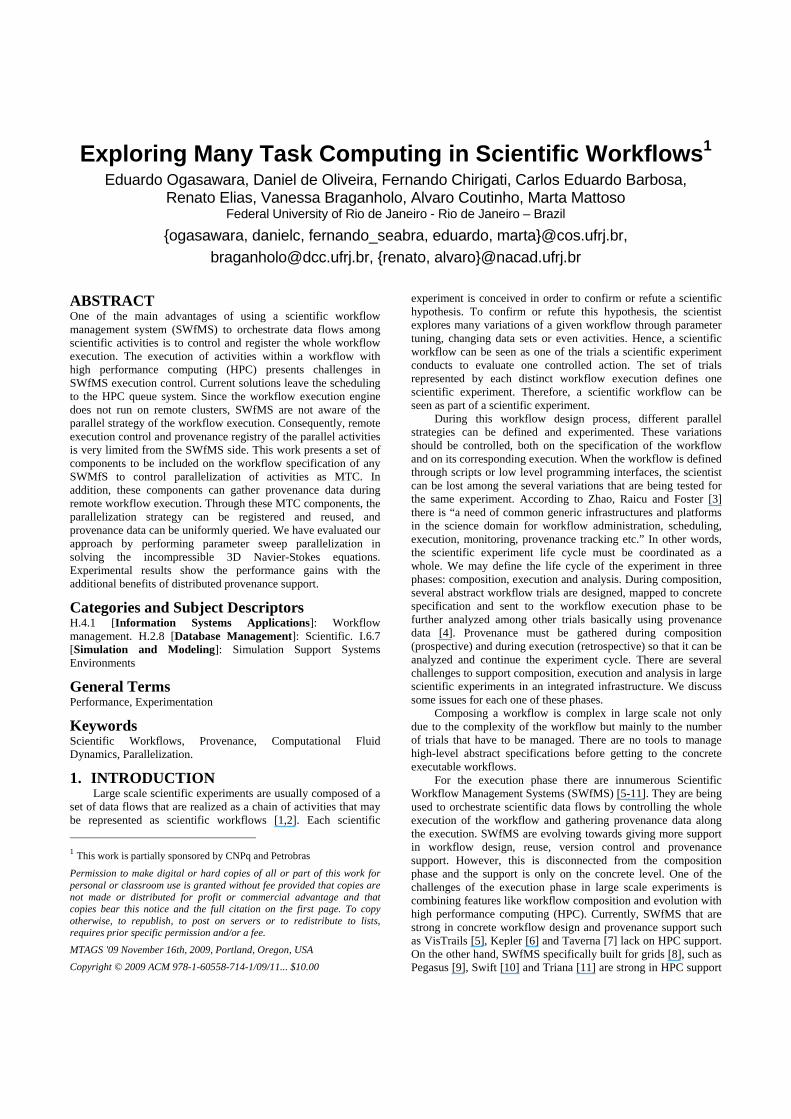
There are many different types of workflow parallelisms [16,17]. In this paper, we explore two types: parameter sweep [18,19] parallelism and data parallelism [20]. These two types of parallelism may represent a barrier for the scientist to control, gather and register workflow provenance. Data parallelism can be characterized by the simultaneous execution of one activity ai of the workflow Wf, where each ai execution processes a subset of the entire input data. This parallelism can be achieved by replicating the activity ai in all nodes of the MTC environment and each node having a specific a subset of the entire input data. As an example, suppose a workflow Wf has input data I = {i1}. Assume also that the domain of this input value is Di1 = [1,3,5,7,9,12]. We could define fragments of Di1 by using a fragmentation function f. In the case of the example, we could define that the fragments of Di1 resulting from f(Di1) are Di1-f1 = [1,3], Di1-f2 = [5,7], and Di1-f3 = [9,12]. Notice that the result of fragmentation function needs to be disjoint. The set of output data FOk generated at each k node must be merged in order to produce the final result (Oi), as presented in Figure 1.
Figure 1 Data Parallelism Parameter sweep parallelism is characterized by the
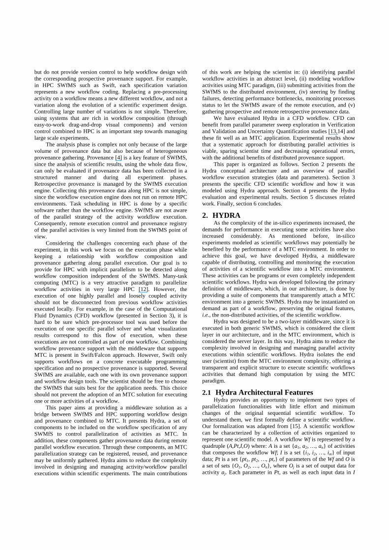
simultaneous execution of one activity of the workflow Wf (or all the activities of Wf), each execution using different values for the parameters Pt. For example, suppose that a given Wf has parameters pt1, pt2 and pt3. Suppose also that the domain of possible values for parameters pt1, pt2 and pt3 is Dpt1 = [x, x’], Dpt2 = [y, y’] Dpt3 = [z, z’]. One instance of one activity ai of Wf may consume values x, y, z for parameters pt1, pt2 and pt3 respectively, and another instance may consume values x’, y’ and z’, and so on. This can be achieved by allocating a different configuration of values for the parameters in Pt at each node of the MTC environment. Formally, these configurations are formed by taking the parameter values from the domain in a given order. Thus, the first configuration uses Dpt1[1] (which denotes the first value in Dpt1), Dpt2[1], and Dpt3[1]. The second configuration uses Dpt1[2], Dpt2[2], and Dpt3[2], and so on. The set of output data Ok generated by the k-th execution needs to be aggregated, since they refer to different executions of the same experiment. Figure 2 illustrates
this kind of parallelism, where the same activity is replicated in n nodes. In this case, I is the same for all nodes.
Hydra provides a systematic approach to support these two types of parallelism with heterogeneous distributed provenance gathering. Hydra is decoupled from the enactment workflow engine, and has some other features: (i) Hydra components act in a transparent mode, by isolating the scientist from the complexity of the MTC environment; (ii) it allows scientists to monitor legacy applications on distributed resources through its provenance data; and (iii) it provides a loosely coupled interaction between the local SWfMS and the distributed MTC environment. These features guided us to an architecture in which Hydra is simple to deploy and able to be architecturally linked to any local SWfMS with minimum effort. The architecture is described in the next sub-section.
Figure 2 Parameter Sweep Parallelism
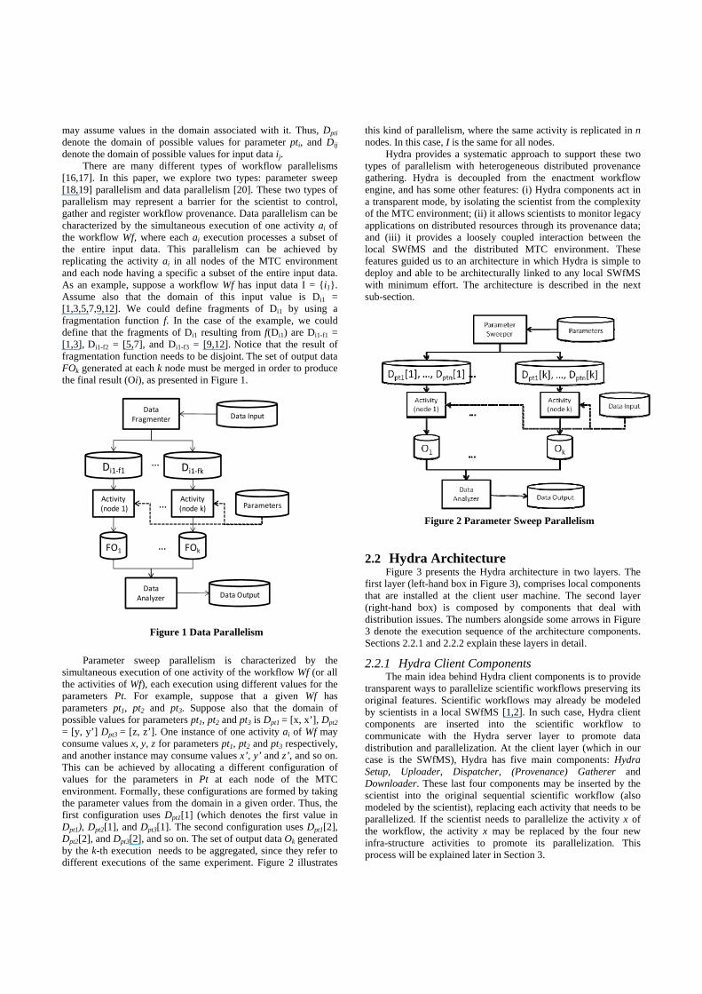
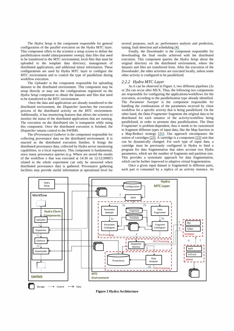
2.2 Hydra Architecture Figure 3 presents the Hydra architecture in two layers. The
first layer (left-hand box in Figure 3), comprises local components that are installed at the client user machine. The second layer (right-hand box) is composed by components that deal with distribution issues. The numbers alongside some arrows in Figure 3 denote the execution sequence of the architecture components. Sections 2.2.1 and 2.2.2 explain these layers in detail.
2.2.1 Hydra Client Components The main idea behind Hydra client components is to provide
transparent ways to parallelize scientific workflows preserving its original features. Scientific workflows may already be modeled by scientists in a local SWfMS [1,2]. In such case, Hydra client components are inserted into the scientific workflow to communicate with the Hydra server layer to promote data distribution and parallelization. At the client layer (which in our case is the SWfMS), Hydra has five main components: Hydra Setup, Uploader, Dispatcher, (Provenance) Gatherer and Downloader. These last four components may be inserted by the scientist into the original sequential scientific workflow (also modeled by the scientist), replacing each activity that needs to be parallelized. If the scientist needs to parallelize the activity x of the workflow, the activity x may be replaced by the four new infra-structure activities to promote its parallelization. This process will be explained later in Section 3.
Data InputData
Fragmenter
Di1‐f1 Di1‐fk…
ParametersActivity(node 1)
Activity (node k)…
DataAnalyzer
FO1 FOk…
Data Output
The Hydra Setup is the component responsible for general configuration of the parallel execution on the Hydra MTC layer. This component offers to the scientist a setup screen to define the parallelization model (data/parameter sweep); data files that need to be transferred to the MTC environment; local files that must be uploaded to the template data directory; management of distributed applications; and additional minor information. These configurations are used by Hydra MTC layer to configure the MTC environment and to control the type of parallelism during workflow execution.
The Uploader is the component responsible for uploading datasets to the distributed environment. This component may be setup directly or may use the configurations registered on the Hydra Setup component to obtain the datasets and files that need to be transferred to the MTC environment.
Once the data and applications are already transferred to the distributed environment, the Dispatcher launches the execution process of the distributed activity on the MTC environment. Additionally, it has monitoring features that allows the scientist to monitor the status of the distributed applications that are running. The execution on the distributed site is transparent while using this component. Once the distributed execution is finished, the Dispatcher returns control to the SWfMS.
The (Provenance) Gatherer is the component responsible for collecting provenance data on the distributed environment. It is enacted as the distributed execution finishes. It brings the distributed provenance data, collected by Hydra server monitoring capabilities, to a local repository. This component is fundamental, since many provenance queries (e.g. Where are stored the results of the workflow x that was executed at 14:30 on 12/12/2008?) related to the whole experiment can only be answered when distributed provenance data is gathered. Provenance gathering facilities may provide useful information at operational level for
several purposes, such as: performance analysis and prediction, tuning, fault detection and scheduling [4].
Finally, the Downloader is the component responsible for downloading the final results achieved with the distributed execution. This component queries the Hydra Setup about the original directory on the distributed environment, where the datasets and files are transferred from. After the execution of the Downloader, the other activities are executed locally, unless some other activity is configured to be parallelized.
2.2.2 Hydra MTC Layer As it can be observed in Figure 3, two different pipelines (2a
or 2b) can occur after MUX. Thus, the following two components are responsible for configuring the applications/workflows for the execution, according to the parallelization type already identified. The Parameter Sweeper is the component responsible for handling the combinations of the parameters received by client workflow for a specific activity that is being parallelized. On the other hand, the Data Fragmenter fragments the original data to be distributed for each instance of the activity/workflow being parallelized, in order to promote data parallelization. The Data Fragmenter is problem-dependent, thus it needs to be customized to fragment different types of input data, like the Map function in a Map-Reduce strategy [21]. Our approach encompasses the notion of cartridges [22]. A cartridge is a component [22] unit that can be dynamically changed. For each type of input data, a cartridge must be previously configured in Hydra to bind a program for data fragmentation that takes account two Hydra parameters, which are the number of fragments and partition size. This provides a systematic approach for data fragmentation, which can be further improved to adaptive virtual fragmentation.
Once a given input dataset is fragmented in different parts, each part is consumed by a replica of an activity instance. As
Provenance
Fragment
Falkon
Workflow
MTC Environment
PBS
VisTrails
SwiftDownloader
Uploader
Dispatcher
Gatherer
MUX
ParameterSweeper
DataFragmenter
ParameterCataloguer
FragmentCataloguer
Template
DataAnalyzer
DispatcherMonitor
Scheduler
SWfMS
Pre‐Processing
Hydra MTC Layer
1
2
2a 2b
3a 3b
4
5
6 7
8
9
10
11
12
Configuration
HydraSetup
SWfMS
Hydra Client Components
MTC Processing
Post‐Processing
Storage Control Data
Figure 3 Hydra Architecture
mentioned before, this activity may be a single program or a whole workflow.
After choosing the activity to be distributed, the components responsible for configuring the distributed environment must be enacted. In case of data parallelism, the Fragment Cataloguer is responsible for creating the directory structure to store the fragmented data (generated by Data Fragmenter) and parameters. The Fragment Cataloguer reads information from the fragment repository it contains information about data fragment to be distributed in each workspace) and the template repository (it contains information about the data/parameters that must be replicated in each workspace) in order to create isolated workspaces for each data fragment. Each workspace is related to a single distributed activity execution. The workspace includes the distributed activity, data files and parameters needed for the execution of the activity. The Parameter Cataloguer only reads information from the template repository in order to create isolated workspaces for each different set of parameters..
These replicated data come from the template repository. Some files of the template repository are instrumented with tags, similar to Java Server Pages (JSP) tags [23], to differentiate each parameter or data fragment. Both the Fragment Cataloguer and the Parameter Cataloguer resolve each instrumented file in each different replicated directory to support the execution of distributed activities, using the precise parameter or data fragment.
After the whole environment is configured, the Dispatcher Monitor is enacted. This component is responsible for invoking external schedulers (such as Torque [24] or Falkon [10]) to execute the activity/workflow in the distributed environment. It is important to emphasize that Hydra is not limited to work with a specific scheduler. Indeed, a cartridge may be developed to enable Hydra to work with different external schedulers. The scheduling problem is addressed by many other approaches, and each approach is adequate for a specific scenario. Thus, Hydra architecture is expansible to address as many pre-existing schedulers as possible.
After invoking the external scheduler, the Dispatcher Monitor continues to monitor the parallel execution. It executes pooling monitoring commands to the external schedulers on the MTC environment to discover the status quo of the execution. Currently, Hydra relies on fault tolerance support of the external scheduler. Nevertheless, this issue should be improved in order to support fault tolerance in the scope of the scientific workflow being executed, as done in other approaches, such as Condor [9]. All the collected execution data and metadata are stored into a Provenance repository on the Hydra MTC layer. This repository contains information about the experiment related to the distributed execution. The Provenance repository was modeled to be able to link the prospective provenance and the retrospective distributed provenance collected during the scientific experiment life cycle. In addition, the Provenance repository was modeled to be compatible to the ongoing effort of the Open Provenance Model (OPM) [25]. OPM is being designed to allow provenance information to be exchanged between SWfMS, by means of a compatibility layer based on a shared provenance model. Hydra stores, in a relational database, both the prospective provenance of the scientific experiment and the distributed part of the retrospective provenance . Nevertheless, due to the fact that the OPM still does not handle distributed execution and prospective provenance, we are still working in associating our provenance schema with the OPM model [27] to support these two challenges.
Currently, our provenance model was only evaluated using VisTrails relational provenance model.
After the execution of the parallel instances is finished, the Data Analyzer component is invoked. This component is responsible for combining the final results (in the case of data parallelization) performing optional merge (aggregation) function to organize the final results to be transferred to the client layer (SWfMS). These aggregation functions have some basic pre-defined routines, but can be customized by cartridges. Particularly in the case of data fragmentation, the cartridge encompasses an equivalent reduce function, as in a Map-Reduce strategy. The Data Analyzer component also stores information on the Provenance repository, since the final results are generated by it and they must be registered for provenance purposes.
3. CASE STUDY This section presents a case study in the area of
Computational Fluid Dynamics (CFD). Engineers and scientists often solve such problems many times, studying the influence on flow features of several parameters, such as viscosity, and Reynolds number. Traditionally, CFD is one of the most demanding areas of scientific computing and it is always on the leading edge of the available supercomputer technology [28]. Recently, there is a growing interest on complex CFD studies involving verification, validation and uncertainty quantification which usually require a massive amount of simulations and generate huge data. This scenario increases the managing complexity of such analyses. Simple scheduling, as in standard many tasks systems, cannot cope with such complexity. Scientific workflows are promising solutions to support such exploratory demands automatically besides providing less error prone environments. Particularly, since the amount of generated data increases dramatically, provenance has a key role in this scenario, and it is supported by scientific workflows.
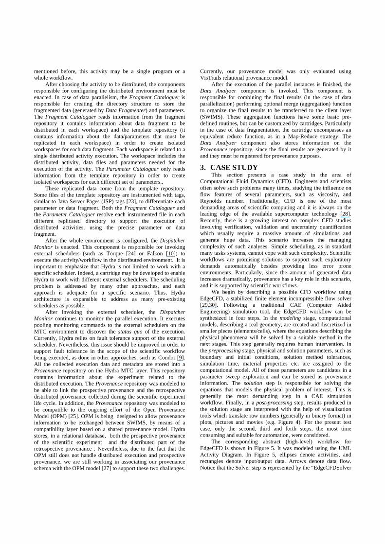
We begin by describing a possible CFD workflow using EdgeCFD, a stabilized finite element incompressible flow solver [29,30]. Following a traditional CAE (Computer Aided Engineering) simulation tool, the EdgeCFD workflow can be synthesized in four steps. In the modeling stage, computational models, describing a real geometry, are created and discretized in smaller pieces (elements/cells), where the equations describing the physical phenomena will be solved by a suitable method in the next stages. This step generally requires human intervention. In the preprocessing stage, physical and solution parameters, such as boundary and initial conditions, solution method tolerances, simulation time, material properties etc. are assigned to the computational model. All of these parameters are candidates in a parameter sweep exploration and can be stored as provenance information. The solution step is responsible for solving the equations that models the physical problem of interest. This is generally the most demanding step in a CAE simulation workflow. Finally, in a post-processing step, results produced in the solution stage are interpreted with the help of visualization tools which translate raw numbers (generally in binary format) in plots, pictures and movies (e.g. Figure 4). For the present test case, only the second, third and forth steps, the most time consuming and suitable for automation, were considered.
The corresponding abstract (high-level) workflow for EdgeCFD is shown in Figure 5. It was modeled using the UML Activity Diagram. In Figure 5, ellipses denote activities, and rectangles denote input/output data. Arrows denote data flow. Notice that the Solver step is represented by the “EdgeCFDSolver
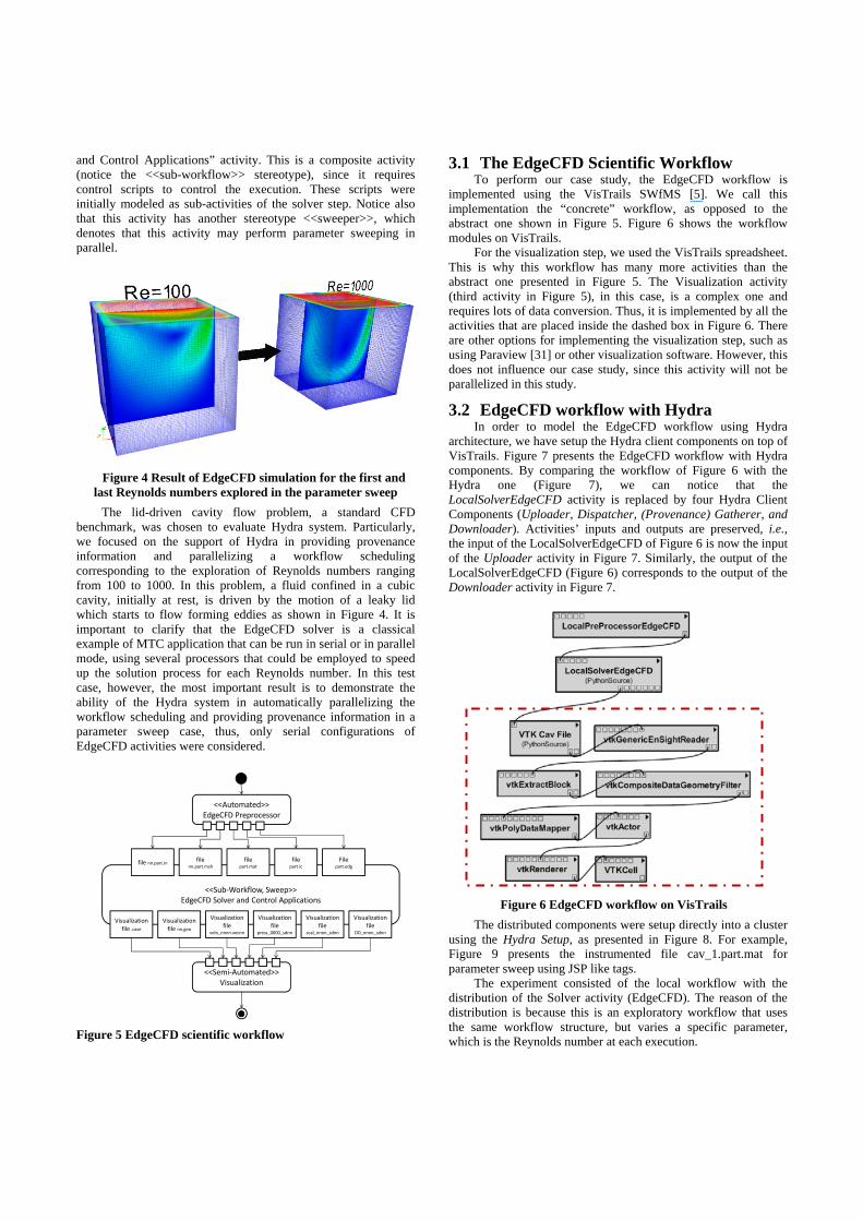
and Control Applications” activity. This is a composite activity (notice the <<sub-workflow>> stereotype), since it requires control scripts to control the execution. These scripts were initially modeled as sub-activities of the solver step. Notice also that this activity has another stereotype <<sweeper>>, which denotes that this activity may perform parameter sweeping in parallel.
Figure 4 Result of EdgeCFD simulation for the first and
last Reynolds numbers explored in the parameter sweep The lid-driven cavity flow problem, a standard CFD
benchmark, was chosen to evaluate Hydra system. Particularly, we focused on the support of Hydra in providing provenance information and parallelizing a workflow scheduling corresponding to the exploration of Reynolds numbers ranging from 100 to 1000. In this problem, a fluid confined in a cubic cavity, initially at rest, is driven by the motion of a leaky lid which starts to flow forming eddies as shown in Figure 4. It is important to clarify that the EdgeCFD solver is a classical example of MTC application that can be run in serial or in parallel mode, using several processors that could be employed to speed up the solution process for each Reynolds number. In this test case, however, the most important result is to demonstrate the ability of the Hydra system in automatically parallelizing the workflow scheduling and providing provenance information in a parameter sweep case, thus, only serial configurations of EdgeCFD activities were considered.
Figure 5 EdgeCFD scientific workflow
3.1 The EdgeCFD Scientific Workflow To perform our case study, the EdgeCFD workflow is
implemented using the VisTrails SWfMS [5]. We call this implementation the “concrete” workflow, as opposed to the abstract one shown in Figure 5. Figure 6 shows the workflow modules on VisTrails.
For the visualization step, we used the VisTrails spreadsheet. This is why this workflow has many more activities than the abstract one presented in Figure 5. The Visualization activity (third activity in Figure 5), in this case, is a complex one and requires lots of data conversion. Thus, it is implemented by all the activities that are placed inside the dashed box in Figure 6. There are other options for implementing the visualization step, such as using Paraview [31] or other visualization software. However, this does not influence our case study, since this activity will not be parallelized in this study.
3.2 EdgeCFD workflow with Hydra In order to model the EdgeCFD workflow using Hydra
architecture, we have setup the Hydra client components on top of VisTrails. Figure 7 presents the EdgeCFD workflow with Hydra components. By comparing the workflow of Figure 6 with the Hydra one (Figure 7), we can notice that the LocalSolverEdgeCFD activity is replaced by four Hydra Client Components (Uploader, Dispatcher, (Provenance) Gatherer, and Downloader). Activities’ inputs and outputs are preserved, i.e., the input of the LocalSolverEdgeCFD of Figure 6 is now the input of the Uploader activity in Figure 7. Similarly, the output of the LocalSolverEdgeCFD (Figure 6) corresponds to the output of the Downloader activity in Figure 7.
Figure 6 EdgeCFD workflow on VisTrails The distributed components were setup directly into a cluster
using the Hydra Setup, as presented in Figure 8. For example, Figure 9 presents the instrumented file cav_1.part.mat for parameter sweep using JSP like tags.
The experiment consisted of the local workflow with the distribution of the Solver activity (EdgeCFD). The reason of the distribution is because this is an exploratory workflow that uses the same workflow structure, but varies a specific parameter, which is the Reynolds number at each execution.
<<Semi‐Automated>>Visualization
<<Automated>>EdgeCFD Preprocessor
<<Sub‐Workflow, Sweep>>EdgeCFD Solver and Control Applications
file nn.part.in file nn.part.msh
file part.mat
filepart.ic
Filepart.edg
Visualizationfile .case
Visualizationfile nn.geo
Visualization file
velo_nnnn.vecnn
Visualization file
press_0000_sdnn
Visualization file
scal_nnnn_sdnn
Visualization file
DD_nnnn_sdnn

Figure 7 EdgeCFD workflow with Hydra Components This case study has evidenced the five main contributions of
Hydra (see Section 1). Initially, the parameter sweep specification (in Figure 5) indicated to Hydra the potential for the (i) implicit parameter parallelism. Then, the scientist is guided to include the required Hydra components to (ii) model the MTC activities as shown in Figure 6. Then, (iii) MTC submission is helped by the configurator (Figure 7) and can be (iv) steered as shown in Figure 8. Finally, (v) provenance gathering shows that, by using Hydra, it is possible to register the prospective provenance for the parameter sweep of the exploratory experiment. Additionally, this would be a laborious activity subjected to human errors if done manually by scientists. In our Hydra infra-structure, this exploratory execution can be run in a MTC environment considering a parameter sweep that generates as many configurations as required for the Solver to run.
Figure 8 EdgeCFD distribution/parallel setup
The implementation of the local components encompasses all the client components explained on Section 2. The Uploader and the Downloader are implemented to connect to the cluster via SSH, and send/receive the data files directly to a repository on the cluster storage. The Dispatcher connects via SSH to MUX on the
Hydra MTC layer to invoke the distributed activity at the MTC environment, which in our example is the Solver.
Figure 9 Instrumented cavity file for parameter sweep Although we use a secure connection to transfer data, there
are many other issues concerning security, which are outside the scope of the present paper. For further information on provenance and security issues see [32,33].
4. EXPERIMENTAL RESULTS The EdgeCFD workflow was invoked by VisTrails from a
desktop and distributed the Solver activity using MTC paradigm into a cluster using the Hydra MTC infra-structure for parallel parameter sweep. The execution of the EdgeCFD workflow using Hydra was performed on HPC3. Hydra MTC infra-structure was setup to use Torque Cartridge as the job scheduler [24] to setup the job submission for the serial version of the EdgeCFD solver for the cavity flow problem described in Section 3.
Through this experiment, we could observe that Hydra middleware provides a systematic approach for supporting the parameter sweep exploration. Initially, we used Hydra Setup to define the parallel configuration for the workflow as presented in Figure 8. This configuration was stored at the Parameter Catalog for the experiment. This Parameter Catalog represents the prospective provenance for the parallel parameter sweep. The configuration files or commands line parameters for each program were then instrumented using tags that are easy to understand, as presented in Figure 9 (please see the selected text). Thus, with the instrumented files and the catalog definition in hand, we needed only to make small changes on the scientific workflow to support the desired parallelism, as presented in Figure 7.
After modifying the workflow, we started its execution. The pre-processing activities were executed on VisTrails, and then the generated files required by EdgeCFDSolver were transferred to the MTC environment. Hydra Client Components invoked Hydra MTC to parallelize the several solver activities. Hydra MTC automatically handles and creates an isolated workspace that includes all needed files for each distributed activity executed at the MTC environment. In the case of the parameter sweep, an individual workspace is created for each set of parameters combination, as presented in section 2.1. Hydra retrospective provenance mechanism registers each workspace and its association to a specific set of parameters used in the parameter sweep exploration. Once all workspaces are created, Hydra MTC dispatches these activities to the local scheduler execution. Each individual activity execution is monitored. The execution catalog represents the retrospective provenance for the parallel Hydra MTC execution. If any error occurs, they are recorded by Hydra retrospective provenance mechanism. Also, execution information for each activity is recorded at the execution catalog. Yet, after all 3 SGI Altix ICE 8200 with 64 nodes with Intel Xeon 8-core procs/node
installed at the High Performance Computing Center, COPPE/ UFRJ.
activities are completed, the execution control returns to VisTrails. The Gatherer sends the retrospective provenance from the MTC environment back to the SWfMS (VisTrails).
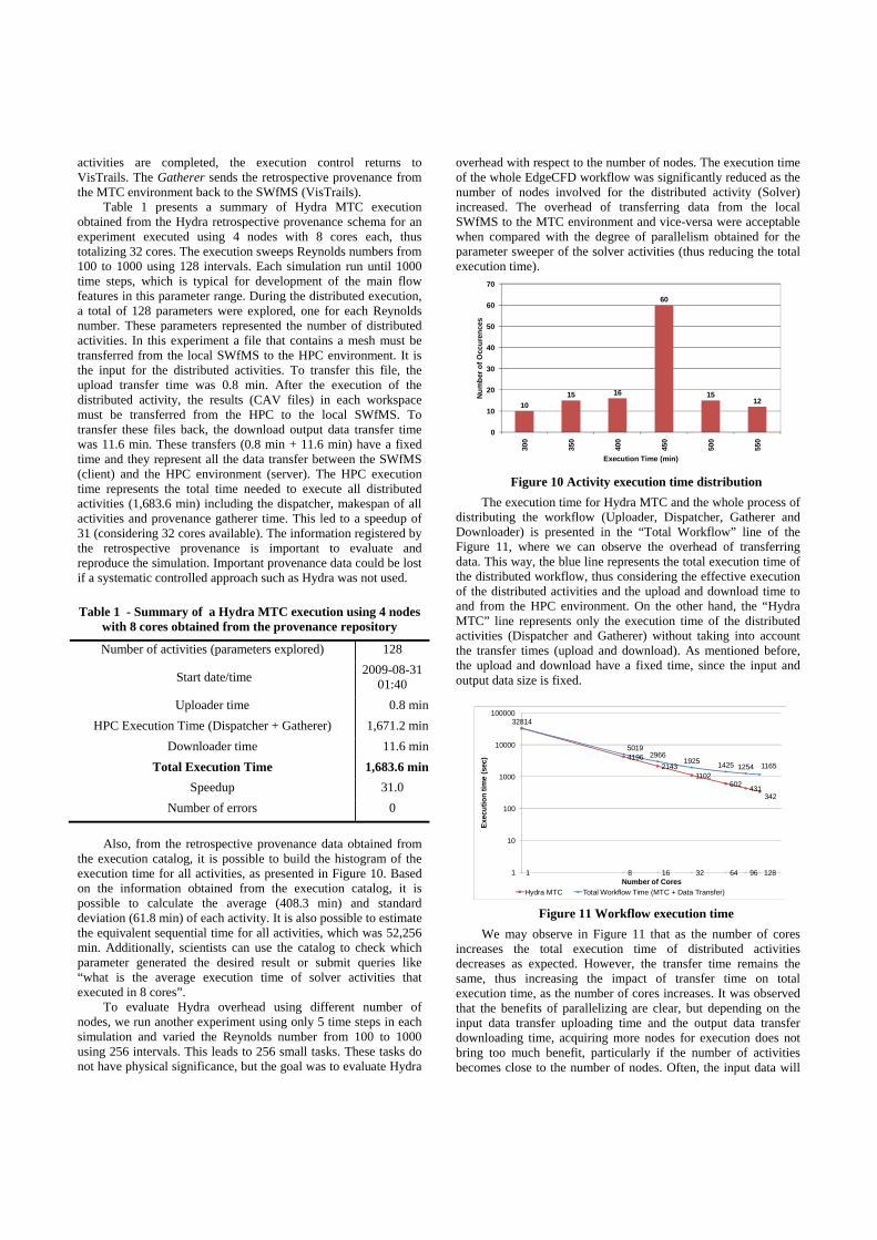
Table 1 presents a summary of Hydra MTC execution obtained from the Hydra retrospective provenance schema for an experiment executed using 4 nodes with 8 cores each, thus totalizing 32 cores. The execution sweeps Reynolds numbers from 100 to 1000 using 128 intervals. Each simulation run until 1000 time steps, which is typical for development of the main flow features in this parameter range. During the distributed execution, a total of 128 parameters were explored, one for each Reynolds number. These parameters represented the number of distributed activities. In this experiment a file that contains a mesh must be transferred from the local SWfMS to the HPC environment. It is the input for the distributed activities. To transfer this file, the upload transfer time was 0.8 min. After the execution of the distributed activity, the results (CAV files) in each workspace must be transferred from the HPC to the local SWfMS. To transfer these files back, the download output data transfer time was 11.6 min. These transfers (0.8 min + 11.6 min) have a fixed time and they represent all the data transfer between the SWfMS (client) and the HPC environment (server). The HPC execution time represents the total time needed to execute all distributed activities (1,683.6 min) including the dispatcher, makespan of all activities and provenance gatherer time. This led to a speedup of 31 (considering 32 cores available). The information registered by the retrospective provenance is important to evaluate and reproduce the simulation. Important provenance data could be lost if a systematic controlled approach such as Hydra was not used.
Table 1 - Summary of a Hydra MTC execution using 4 nodes with 8 cores obtained from the provenance repository
Number of activities (parameters explored) 128
Start date/time 2009-08-31 01:40
Uploader time 0.8 minHPC Execution Time (Dispatcher + Gatherer) 1,671.2 min
Downloader time 11.6 minTotal Execution Time 1,683.6 min
Speedup 31.0 Number of errors 0
Also, from the retrospective provenance data obtained from
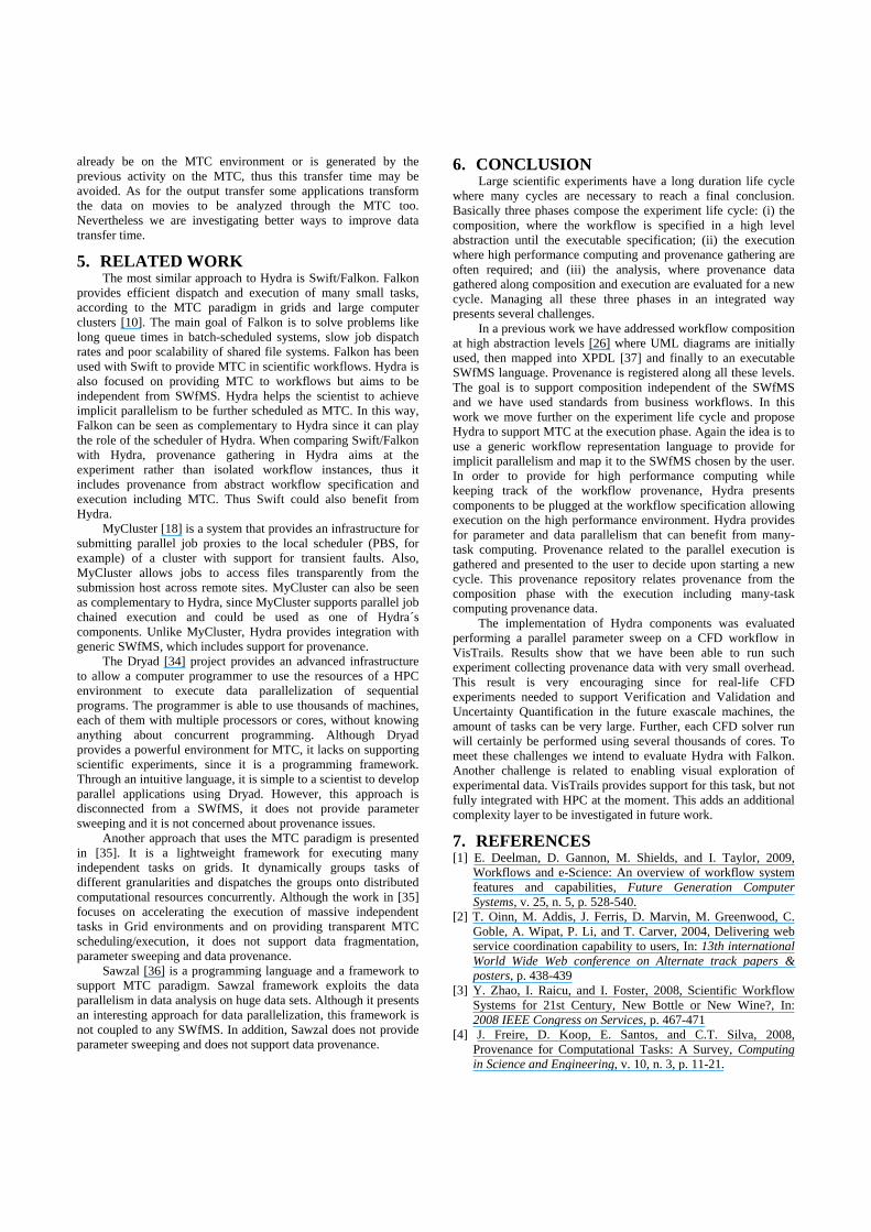
the execution catalog, it is possible to build the histogram of the execution time for all activities, as presented in Figure 10. Based on the information obtained from the execution catalog, it is possible to calculate the average (408.3 min) and standard deviation (61.8 min) of each activity. It is also possible to estimate the equivalent sequential time for all activities, which was 52,256 min. Additionally, scientists can use the catalog to check which parameter generated the desired result or submit queries like “what is the average execution time of solver activities that executed in 8 cores”.
To evaluate Hydra overhead using different number of nodes, we run another experiment using only 5 time steps in each simulation and varied the Reynolds number from 100 to 1000 using 256 intervals. This leads to 256 small tasks. These tasks do not have physical significance, but the goal was to evaluate Hydra
overhead with respect to the number of nodes. The execution time of the whole EdgeCFD workflow was significantly reduced as the number of nodes involved for the distributed activity (Solver) increased. The overhead of transferring data from the local SWfMS to the MTC environment and vice-versa were acceptable when compared with the degree of parallelism obtained for the parameter sweeper of the solver activities (thus reducing the total execution time).
Figure 10 Activity execution time distribution
The execution time for Hydra MTC and the whole process of distributing the workflow (Uploader, Dispatcher, Gatherer and Downloader) is presented in the “Total Workflow” line of the Figure 11, where we can observe the overhead of transferring data. This way, the blue line represents the total execution time of the distributed workflow, thus considering the effective execution of the distributed activities and the upload and download time to and from the HPC environment. On the other hand, the “Hydra MTC” line represents only the execution time of the distributed activities (Dispatcher and Gatherer) without taking into account the transfer times (upload and download). As mentioned before, the upload and download have a fixed time, since the input and output data size is fixed.
Figure 11 Workflow execution time
We may observe in Figure 11 that as the number of cores increases the total execution time of distributed activities decreases as expected. However, the transfer time remains the same, thus increasing the impact of transfer time on total execution time, as the number of cores increases. It was observed that the benefits of parallelizing are clear, but depending on the input data transfer uploading time and the output data transfer downloading time, acquiring more nodes for execution does not bring too much benefit, particularly if the number of activities becomes close to the number of nodes. Often, the input data will
1015 16
60
1512
0
10
20
30
40
50
60
70
300
350
400
450
500
550
Num
ber o
f Occ
uren
ces
Execution Time (min)
41962143
1102602 431
342
32814
50192966
1925 1425 1254 1165
1 8 16 32 64 96 1281
10
100
1000
10000
100000
Exec
utio
n tim
e (s
ec)
Number of CoresHydra MTC Total Workflow Time (MTC + Data Transfer)
already be on the MTC environment or is generated by the previous activity on the MTC, thus this transfer time may be avoided. As for the output transfer some applications transform the data on movies to be analyzed through the MTC too. Nevertheless we are investigating better ways to improve data transfer time.
5. RELATED WORK The most similar approach to Hydra is Swift/Falkon. Falkon
provides efficient dispatch and execution of many small tasks, according to the MTC paradigm in grids and large computer clusters [10]. The main goal of Falkon is to solve problems like long queue times in batch-scheduled systems, slow job dispatch rates and poor scalability of shared file systems. Falkon has been used with Swift to provide MTC in scientific workflows. Hydra is also focused on providing MTC to workflows but aims to be independent from SWfMS. Hydra helps the scientist to achieve implicit parallelism to be further scheduled as MTC. In this way, Falkon can be seen as complementary to Hydra since it can play the role of the scheduler of Hydra. When comparing Swift/Falkon with Hydra, provenance gathering in Hydra aims at the experiment rather than isolated workflow instances, thus it includes provenance from abstract workflow specification and execution including MTC. Thus Swift could also benefit from Hydra.
MyCluster [18] is a system that provides an infrastructure for submitting parallel job proxies to the local scheduler (PBS, for example) of a cluster with support for transient faults. Also, MyCluster allows jobs to access files transparently from the submission host across remote sites. MyCluster can also be seen as complementary to Hydra, since MyCluster supports parallel job chained execution and could be used as one of Hydra´s components. Unlike MyCluster, Hydra provides integration with generic SWfMS, which includes support for provenance.
The Dryad [34] project provides an advanced infrastructure to allow a computer programmer to use the resources of a HPC environment to execute data parallelization of sequential programs. The programmer is able to use thousands of machines, each of them with multiple processors or cores, without knowing anything about concurrent programming. Although Dryad provides a powerful environment for MTC, it lacks on supporting scientific experiments, since it is a programming framework. Through an intuitive language, it is simple to a scientist to develop parallel applications using Dryad. However, this approach is disconnected from a SWfMS, it does not provide parameter sweeping and it is not concerned about provenance issues.
Another approach that uses the MTC paradigm is presented in [35]. It is a lightweight framework for executing many independent tasks on grids. It dynamically groups tasks of different granularities and dispatches the groups onto distributed computational resources concurrently. Although the work in [35] focuses on accelerating the execution of massive independent tasks in Grid environments and on providing transparent MTC scheduling/execution, it does not support data fragmentation, parameter sweeping and data provenance.
Sawzal [36] is a programming language and a framework to support MTC paradigm. Sawzal framework exploits the data parallelism in data analysis on huge data sets. Although it presents an interesting approach for data parallelization, this framework is not coupled to any SWfMS. In addition, Sawzal does not provide parameter sweeping and does not support data provenance.
6. CONCLUSION Large scientific experiments have a long duration life cycle
where many cycles are necessary to reach a final conclusion. Basically three phases compose the experiment life cycle: (i) the composition, where the workflow is specified in a high level abstraction until the executable specification; (ii) the execution where high performance computing and provenance gathering are often required; and (iii) the analysis, where provenance data gathered along composition and execution are evaluated for a new cycle. Managing all these three phases in an integrated way presents several challenges.
In a previous work we have addressed workflow composition at high abstraction levels [26] where UML diagrams are initially used, then mapped into XPDL [37] and finally to an executable SWfMS language. Provenance is registered along all these levels. The goal is to support composition independent of the SWfMS and we have used standards from business workflows. In this work we move further on the experiment life cycle and propose Hydra to support MTC at the execution phase. Again the idea is to use a generic workflow representation language to provide for implicit parallelism and map it to the SWfMS chosen by the user. In order to provide for high performance computing while keeping track of the workflow provenance, Hydra presents components to be plugged at the workflow specification allowing execution on the high performance environment. Hydra provides for parameter and data parallelism that can benefit from many-task computing. Provenance related to the parallel execution is gathered and presented to the user to decide upon starting a new cycle. This provenance repository relates provenance from the composition phase with the execution including many-task computing provenance data.
The implementation of Hydra components was evaluated performing a parallel parameter sweep on a CFD workflow in VisTrails. Results show that we have been able to run such experiment collecting provenance data with very small overhead. This result is very encouraging since for real-life CFD experiments needed to support Verification and Validation and Uncertainty Quantification in the future exascale machines, the amount of tasks can be very large. Further, each CFD solver run will certainly be performed using several thousands of cores. To meet these challenges we intend to evaluate Hydra with Falkon. Another challenge is related to enabling visual exploration of experimental data. VisTrails provides support for this task, but not fully integrated with HPC at the moment. This adds an additional complexity layer to be investigated in future work.
7. REFERENCES [1] E. Deelman, D. Gannon, M. Shields, and I. Taylor, 2009,
Workflows and e-Science: An overview of workflow system features and capabilities, Future Generation Computer Systems, v. 25, n. 5, p. 528-540.
[2] T. Oinn, M. Addis, J. Ferris, D. Marvin, M. Greenwood, C. Goble, A. Wipat, P. Li, and T. Carver, 2004, Delivering web service coordination capability to users, In: 13th international World Wide Web conference on Alternate track papers & posters, p. 438-439
[3] Y. Zhao, I. Raicu, and I. Foster, 2008, Scientific Workflow Systems for 21st Century, New Bottle or New Wine?, In: 2008 IEEE Congress on Services, p. 467-471
[4] J. Freire, D. Koop, E. Santos, and C.T. Silva, 2008, Provenance for Computational Tasks: A Survey, Computing in Science and Engineering, v. 10, n. 3, p. 11-21.
[5] S.P. Callahan, J. Freire, E. Santos, C.E. Scheidegger, C.T. Silva, and H.T. Vo, 2006, VisTrails: visualization meets data management, In: Proceedings of the 2006 ACM SIGMOD, p. 745-747, Chicago, IL, USA.
[6] I. Altintas, C. Berkley, E. Jaeger, M. Jones, B. Ludascher, and S. Mock, 2004, Kepler: an extensible system for design and execution of scientific workflows, In: 16th SSDBM, p. 423-424, Santorini, Greece.
[7] D. Hull, K. Wolstencroft, R. Stevens, C. Goble, M.R. Pocock, P. Li, and T. Oinn, 2006, Taverna: a tool for building and running workflows of services, Nucleic Acids Research, v. 34, n. Web Server issue, p. 729-732.
[8] J. Yu and R. Buyya, 2005, A Taxonomy of Workflow Management Systems for Grid Computing, Journal of Grid Computing, v. 34, n. 3-4, p. 171-200.
[9] E. Deelman, G. Mehta, G. Singh, M. Su, and K. Vahi, 2007, "Pegasus: Mapping Large-Scale Workflows to Distributed Resources", Workflows for e-Science, Springer, p. 376-394.
[10] I. Raicu, Y. Zhao, C. Dumitrescu, I. Foster, and M. Wilde, 2007, Falkon: a Fast and Light-weight tasK executiON framework, In: 2007 ACM/IEEE conference on Supercomputing, p. 1-12, Reno, Nevada.
[11] I. Taylor, M. Shields, I. Wang, and A. Harrison, 2007, "The Triana Workflow Environment: Architecture and Applications", Workflows for e-Science, Springer, p. 320-339.
[12] I. Raicu, I. Foster, and Yong Zhao, 2008, Many-task computing for grids and supercomputers, In: Workshop on Many-Task Computing on Grids and Supercomputers, p. 1-11
[13] D.L. Brown, J. Bell, D. Estep, W. Gropp, B. Hendrickson, S. Keller-McNulty, D. Keyes, J.T. Oden, L. Petzold, et al., 2008, Applied Mathematics at the U.S. Department of Energy: Past, Present and a View to the Future. URL: http://www.osti.gov/bridge/servlets/purl/944335-d7sRna/.
[14] M.S.[. Eldred, H.[. Agarwal, V.M.[. Perez, S.F.[. Wojtkiewicz, and J.E.[. Renaud, 2007, Investigation of reliability method formulations in DAKOTA/UQ, Structure & Infrastructure Engineering: Maintenance, Management, Life-Cycl, v. 3 (Sep.), p. 199-213.
[15] L.A. Meyer, S.C. Rössle, P.M. Bisch, and M. Mattoso, 2005, "Parallelism in Bioinformatics Workflows", High Performance Computing for Computational Science - VECPAR 2004, , p. 583-597.
[16] R.S. Barga, D. Fay, D. Guo, S. Newhouse, Y. Simmhan, and A. Szalay, 2008, Efficient scheduling of scientific workflows in a high performance computing cluster, In: 6th international workshop on Challenges of large applications in distributed environments, p. 63-68, Boston, MA, USA.
[17] W.M.P.V.D. Aalst, A.H.M.T. Hofstede, B. Kiepuszewski, and A.P. Barros, 2003, Workflow Patterns, Distrib. Parallel Databases, v. 14, n. 1, p. 5-51.
[18] E. Walker and C. Guiang, 2007, Challenges in executing large parameter sweep studies across widely distributed computing environments, In: 5th IEEE workshop on Challenges of large applications in distributed environments, p. 11-18, Monterey, California, USA.
[19] M.E. Samples, J.M. Daida, M. Byom, and M. Pizzimenti, 2005, Parameter sweeps for exploring GP parameters, In: 2005 workshops on Genetic and evolutionary computation, p. 212-219, Washington, D.C.
[20] L. Meyer, D. Scheftner, J. Vöckler, M. Mattoso, M. Wilde, and I. Foster, 2007, "An Opportunistic Algorithm for Scheduling Workflows on Grids", High Performance Computing for Computational Science - VECPAR 2006, , p. 1-12.
[21] J. Dean and S. Ghemawat, 2008, MapReduce: simplified data processing on large clusters, Commun. ACM, v. 51, n. 1, p. 107-113.
[22] C. Szyperski, 1997, Component Software: Beyond Object-Oriented Programming. Addison-Wesley Professional.
[23] H. Bergsten, 2003, JavaServer pages. O'Reilly Media, Inc. [24] A. Bayucan, R.L. Henderson, and J.P. Jones, 2000, Portable
Batch System Administration Guide, Veridian System [25] L. Moreau, J. Freire, J. Futrelle, R. McGrath, J. Myers, and P.
Paulson, 2008, "The Open Provenance Model: An Overview", Provenance and Annotation of Data and Processes, , p. 323-326.
[26] E. Ogasawara, C. Paulino, L. Murta, C. Werner, and M. Mattoso, 2009, Experiment Line: Software Reuse in Scientific Workflows, In: 21th SSDBM, p. 264–272, New Orleans, LA.
[27] A. Marinho, L. Murta, C. Werner, V. Braganholo, S.M.S.D. Cruz, and M. Mattoso, 2009, A Strategy for Provenance Gathering in Distributed Scientific Workflows, In: IEEE International Workshop on Scientific Workflows, Los Angeles, California, United States.
[28] D.A. Bader, 2008, Petascale computing: algorithms and applications. Chapman & Hall/CRC.
[29] R.N. Elias and A.L.G.A. Coutinho, 2007, Stabilized edge-based finite element simulation of free-surface flows, International Journal for Numerical Methods in Fluids, v. 54, n. 6-8, p. 965-993.
[30] R.N. Elias, V. Braganholo, J. Clarke, M. Mattoso, and A.L. Coutinho, 2009, Using XML with large parallel datasets: is ther any hope?, In: Parallel Computational Fluid Dynamics (ParCFD)
[31] Paraview, 2009, Paraview, http://www.paraview.org. [32] L. Gadelha and M. Mattoso, 2008, Kairos: An Architecture
for Securing Authorship and Temporal Information of Provenance Data in Grid-Enabled Workflow Management Systems, In: International Workshop on Scientific Workflows and Business Workflow Standards in e-Science (SWBES 2008), p. 597-602
[33] R. Hasan, R. Sion, and M. Winslett, 2007, Introducing secure provenance: problems and challenges, In: Proceedings of the 2007 ACM workshop on Storage security and survivability, p. 13-18, Alexandria, Virginia, USA.
[34] M. Isard, M. Budiu, Y. Yu, A. Birrell, and D. Fetterly, 2007, Dryad: distributed data-parallel programs from sequential building blocks, In: 2nd ACM SIGOPS/EuroSys European Conference on Computer Systems, p. 72, 59, Lisbon, Portugal.
[35] Li Hui, Huashan Yu, and Li Xiaoming, 2008, A lightweight execution framework for massive independent tasks, In: Workshop on Many-Task Computing on Grids and Supercomputers, 2008, p. 1-9
[36] R. Pike, S. Dorward, R. Griesemer, and S. Quinlan, 2005, Interpreting the data: Parallel analysis with Sawzall, Sci. Program., v. 13, n. 4, p. 277-298.
[37] I. WfMC, 2009, Binding, WfMC Standards, WFMC-TC-1023, http://www. wfmc. org, 2000.