test of a full scale roof truss - scholars' mine
TRANSCRIPT
Missouri University of Science and Technology Missouri University of Science and Technology
Scholars' Mine Scholars' Mine
International Specialty Conference on Cold-Formed Steel Structures
(1992) - 11th International Specialty Conference on Cold-Formed Steel Structures
Aug 20th, 12:00 AM - Aug 21st, 12:00 AM
Test of a Full Scale Roof Truss Test of a Full Scale Roof Truss
Yao - Jie Guo
Shan-Feng Fang
Follow this and additional works at: https://scholarsmine.mst.edu/isccss
Part of the Structural Engineering Commons
Recommended Citation Recommended Citation Guo, Yao - Jie and Fang, Shan-Feng, "Test of a Full Scale Roof Truss" (1992). International Specialty Conference on Cold-Formed Steel Structures. 4. https://scholarsmine.mst.edu/isccss/11iccfss/11iccfss-session7/4
This Article - Conference proceedings is brought to you for free and open access by Scholars' Mine. It has been accepted for inclusion in International Specialty Conference on Cold-Formed Steel Structures by an authorized administrator of Scholars' Mine. This work is protected by U. S. Copyright Law. Unauthorized use including reproduction for redistribution requires the permission of the copyright holder. For more information, please contact [email protected].

Eleventh International Specialty Conference on Cold-Formed Steel Structures St. Louis, Missouri, U,S.A., Odober 20-21, 1992
TEST OF A FULL SCALE ROOF TRUSS
Yao - Jie Guo' and Shan - Feng FangZ
SUMMARY
In order to obtain information of ultimate capacity and destructive characteriltics of a roof truss, the test of a full scale roof truss was carried oul Based on the test results this article has analysed the destructive mechanism and presented the suggestions of improvement to design and fabrication,
1. INTRODUCTION
There is a industrial building its overal1 length and width are 709 feet (216m) and 2x98.5 feet (2 x 30m) respectively. The distances between columns are 19.5 feet (6m) along left or right side-row columns and 39 feet (12m) along mid -row columns. Roof trusses were symmetrically placed along the ridge line and simply snpported on mid - row columns or joists and left or right side - row columns. The top chord of each roof truss is inclined with a slope of 1: 2 as shown in Fig. L The spans of roof trusses are 98.5 feet (30m). Purlins and desks are cold - formed steel shapes and profiled steel sheetings respectively. The vertical design load applied at each loading joint of this roof truss is 4.5 kip (20kN).
These roof trusses were fabricated in lieldside and each of their members was made of two cold - formed lipped channels connected by welding lip to lip.
The sizes of the members and the fabricated conditions of the testing truss were all the same as the actual roof trusses. The purpose of this test was to obtain information of ultimate load -carrying capacity of this truss and destructive charaleristics etc. On the basis of test results we have analysed the destructive mechanism and presented the suggestions of improvement of design and fabrication.
2. OUTLINE OF TEST
2.1 Basic data of members and joints
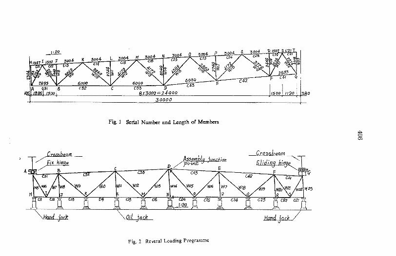
Fig. 1 shows the serial rumber of the members and their lengths. There are four sizes of cross sections used in this truss. Their plate thicknesses and web depths are all equal to 1/12 In. (4.Smm) and 4 in. (10Omm) respectively, but their flange widths are di.fl'erent, the flange widths of top and bottom chords are equal to 6 -1/4 in. (16Omm) and S -1/2 in. (14Omm) respectively, the flange widths of web members are 4 in. (lOOmm) for W5, WI0, W18, W20 and W23 and 4 -3/4 in. ( 120mm) for other web members.
L Lecturer of Civ. Engrg .• Wuhan Univ. of Hydro- Electric Engrs Hube~ CHINA. 2. Professor of Civ. Engrs. Wuhan Univ. of Hydro - Electric Engrg Hub~ CHINA.
30000
Fig. 1 Serial Number and Length of Members
c!5 Qj
Crosshe~
"/ r:ix hill$.!! - . t: F '-cam A * /B- * 03 /\\.< C~3 /K: C42 /K q:J &1 K (3Z
Fig. 2 ReveraJ Loading Programme
407
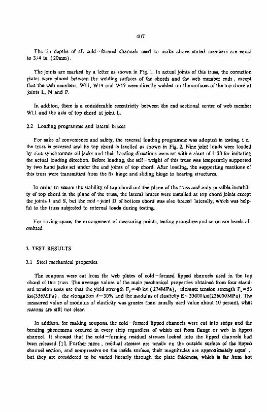
The lip depths of all cold - formed channels UlIed to make above stated members are equal to 3/4 in. (20mm).
The joints are marked by a letter as shown in Fig. 1. In actual joints of this truss, the connetion plates were placed between the welding surfaces of the chords and the web member ends , except that the web members, WH. WI4 and W17 were directly welded on the surfaces oftbe top chord at joints L, N and P.
In additon. there is a considerable eccentricity between the end sectional center of web member Wll and the axis of top chord at joint L.
2.2 Loading programme and lateral braces
For sake of convenience and safety, the reversal loading programme was adopted in testing. i e. the truss is reversed and its top chord is levelled as shown in Fig. 2. Nine joint loads were loaded by nine synchronous oil jacks and their loading directions were set with a slant of 1: 20 for imitating the actual loading direction. Before loading, the self-weight of tbis truss was temperarily supported by two hand jacks set under the end joints of top chord. After loading, the supporting reactions of this truss were transmitted from the fix binge and sliding binge to bearing structures.
In order to assure the stability of top chord out the plane of the truss and only possible instability of top chord in the plane of the truss, the lateral braces were installed at top chord jointll except the joints I and S, but the mid - joint D of bottom chord was also braced laterally, whlch waa helpful to the truss subjected to external loads during testing.
For saving space, the arrangement of measuring points, testing procedu.re and 80 on are herein all omitted.
3. TEST RESULTS
3.1 Steel mechanical properties
The coupons were cut from the web plates of cold - formed lipped channels UlIed in the top chord of thls truss. The average values of the main mechanical properties obtained from four standard tension tests are that the yield strength F, = 40 ksi ( 274MPa), ultimate tension strength F. = S3 ksi(3S6MPa), the elongation 0 = 30% and the modulus of elasticity E = 33000 ksi(226000MPa). 'Ibt measured value of Illodulus of elasticity was graeter than usually used value about 10 percent, what reasons are still not clear.
In additon, for making coupons, the cold -formed lipped channels were cut into strips and the bending phenomena occured in every strip regardless of whlch cut from flange or web in lipped channel. It showed that the cold - forming residual stresses locked into the lipped channels had been released [1]. Further more, residual stresses are tensile on the outside surface of the lipped channel section, and compressive on the inside surface, their magnitudes are approximatel, equal. but they are considered to be varied linearly through the plate thlckncss, whlch is rar from hot
408
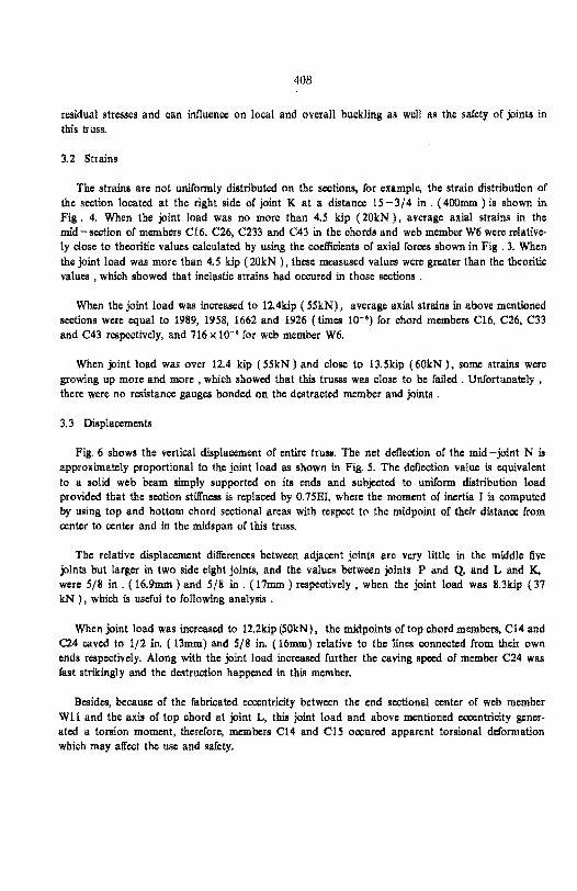
residual stresses and can influence on local and overall buckling as well as the safety of joints in this truss.
3.2 Strains
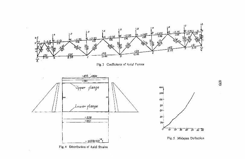
The strains are not uniformly distributed on the sections, for example, the strain distribution of the section located at the right side of joint K at a distance 15 -3/4 in. (400mm) is shown in Fig. 4. When the joint load was no more than 4.5 kip (20kN), average axial strains in the mid - scd:ion of members C16, C26, C233 and C43 in the chords and web member W6 were relatively close to theoritic values calculated by using the coefficients of axial forces shown in Fig. 3. When the joint load was more than 4.5 kip (20kN ), these mcasused values were greater than the theoritic values, which showed that inelastic strains had occured in those sections.
When the joint load was increased to 12.4kip (SSkN), average axial strains in above mentioned sections were equal to 1989, 19S8, 1662 and 1926 (times 10-') for chord members C16, C26, C33 and C43 respectively, and 716 x 10-' for web member W6.
When joint load was over 12.4 kip (SSkN ) and close to 13.Skip (60kN ). some strains were growing up more and more, which showed that this truSlS was close to be failed. Unfortunately, there were no resistance gauges bonded on the destracted member and joints.
3. 3 Displacements
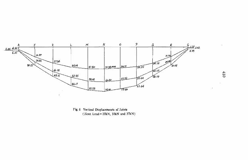
Fig. 6 shows the vertical displacement of entire truss. The net deflection of the mid -joint N is approximately proportional to the joint load as shown in Fig. 5. The deflection value is equivalent to a solid web beam simply supported on its ends and subjected to uniform distribution load provided that the section stiffness is replaced by O.7SEI, where the moment of inertia I is computed by using top and bottom chord sectional areas with respect to the midpoint of their distance from center to center and in the midspan of this truss.
The relative displacement differences between adjacent joints are very little in the middle five joints but larger in two side eight joints, and the values between joints P and Q, and L and K, were 5/8 in. (16.9mm) and 5/8 in. (17mm) respectively, when the joint load was 8.3kip (37 kN ), which is useful to following analysis .
When joint load was increased to 12.2kip (SOkN). the midpoints of top chord members, C14 and C24 caved to 1/2 in. (13mm) and 5/8 in. (16mm) relative to the lines connected from their own ends respectively. Along with the joint load increased further the caving speed of member C24 was fast strikingly and the destruction happened in this member.
Besides, because of the fabricated eccentricity between the end sectional center of web member Wll and the axis of top chord at joint L, this joint load and above mentioned eccentricity generated a torslon moment, therefore, members C14 and C1S occured apparent torsional deformation which may affcd: the use and safety.
1.0
Fig.3 Coefficients of Axial Forces
80
Upper flange
Lower flange
-559 -M61
-6 - 263S{X/O J
Fig.4 Distribution of Axial Strains
mm
120
fO/)
SO
60
4D
20
o· 10 !It; 2!0 4J) 50 ;,., Ill{
Fig. 5 Midspan Deflection
t:; CoO
Lt~ii~ 52.99 5B.as I I -~ ~ ~ HO 0
75.23 I ~5.G4
Fig.6 Vertical Displacements of Joints (Jiont Load = 20kN, 30kN and 37kN)
411
3.4 Destructive characteristics and ultimate load -carrying capacity
When joint load was loaded to 13.Sldp (60kN), only few seconds, the truss was destructed in the order of local buckling of the plate element nearby joint P, the settlement of joint P or the end of web member Wll was compressed into top chord flange, the compression buckling of me mbcr C24 in the plane of tbe truss.
These events happened almost in the same time but it is certain tbat the destruction of this truss stared from the local buckling and failure of tbe joint rather than tbe buckling of the member. The damaged locations were acted by all stresses including axial stress, residual stresses and sub -stress ( or second order stress induced by the stiffness of joints in actual struss and the displacement difference between adjacent joints as the truss loaded) rather than only axial stress.
Owing to the fact that the loading programme was reversal, the ultimate joint load 13.Skip (60kN) involved the joint load 0.63Idp( 2.8kN) induced by the truss self-weight, therefore, actual joint load was 119ldp (S7.2kN) applied on every loading point The ultimate load -carrying capacity was 2.85 times the design load -carrying capacity in this test.
4. ANALYSIS OF DESTRUCTION MECHANISM
In the popular truss design method, assume the joints are ideal hinges and the members are only subjected to axial stresSC8. In fact, there are more or less sub - stresses in the menbers as men tined above. When the panel length to the sectional depth ratios in the chords arc greater than 10, the sub - stresses arc less and can be ignored in designing the truss of hot - rolled steel shapes. However, when designing the truss of cold - formed steel members, because the plate clements of cold - formed sections may be locally buckled and the maximum of cold - forming residual stresses may reach to 0.5F, [1), the sub - stress, cold - forming residual stress and axial stress added together not only may cause the buckling of the plate clement or the member earlier but also may damage the joint. This is why the destruction of the testing truss started from local buckling of the plate clement and failure of the joint.
The design width - thickness ratio of top or bottom flange in top chord of tbe testing truss is 35.6. If cold - forming residual stress is 0.5 F, • when the compression stress sum of axial stress and Bub-stress is greater than 0.5 F, , the elastic width -thickness ratio of the nanga will be greater than 35.6 and the valuc along with the increase of joint load is increased. Because of reaching critical value, the local buckling of the top chord flange nearby the joint P oceurcd first. moreover, the connection plate between the end of web member Wll and the welding surface of top chord at joint P was omitted, and hence, the end of web member Wll was suddenly compressed into the top chord flange, while the joint P was equaivalent to be settled abruptly, so that the displacement dHrerence between joints P and Q was incre.ascd to a greater valuc as to induce a greater sub - stress in the top chord sections nearby joint Q.
Under the coaction of all compression s!rcsses including sub -stress, axial stress and cold -forming residual stress, the most pessimistic section nearby joint Q was squashed and the top chord member C24 • like a member hinged betwcen joint P and the squashed section nearhby joint Q , was buckled at once .
412
Although the axial stresses of the member C16 or C26 is slightly greater than that ofthe member C14 or C24, which can be scen from the Fig. 3, but the displacement differences between the ends of these menbers were that these values of members C16 and C26 were less than those of members C14 and C24. Owing to the settlement of joint P, this value of member C24 Willi greater than that of member C14 and so do the sub-stresses.
It is scen that the failure of member C24 is not surprised.
S. CONCLUSIONS AND SEGGESTIONS
5.1 Ultimate capacity was 285 times design load -carrying capacity in this test and relative deflection of the mid span in this truss was 0.002 IllI the joint load was being 6.7kip (30kN). It is obvious that the design seems too conservative. The enhanced strength due to the effect of cold - forming exceeds O.1F, regardless of the computation in accordance with Chinese Standard (GB118 -87) or the result of stud column test (a complementary test Willi conducted after this truss test had been finished) for cold - formed lipped channels used in this truss.
This strength should be utilized for saving steel.
5.2 The cold - forming residual stress and the sub - stress are of considerable influencoe on the local buckling of plate clements, which may not only cause the instability of members earlier but also damage the joints, If joints are assumed as ideal higned joints in designing this type of trusses, the width - thickness ratio of the plate element in compression chord should be chosen carefully and controlled strickly for paying regard to the harmful effcets as mentioned above.
S.3 It is hardly justifiable in design that the failure of the joint oooured before the member collapsed in the testing truss. For improving the stress states of the plate elements connected with web members, preventing web member ends prone to be compressed into chord at joints and giving auUfanoe that the failure of joints is not prior to the collapse of members in the truss. the conection plates between the ends of web members and the welding surfaces of chords are needed and justified.
5.4 The cold -forming and welding residual stresses exist simutaneously in the sections made of two cold - formed Upped channels connected by welding lip to lip, but the cold - forming residual stresses play an important part in local buckling of flanges of compression chord, and the welding residual stresses are higher tensile stresses on the middle of web plates and lower compressive stresses on top and bottom flanges of the sections. Especially, the cold - forming residual stresses are worthy of note and needed to study further.
5.5 Fabricating eccentricity betwcen the end sectional center of web menbers and the axis of chords should be small IllI far as possible to avoid the considerable torsional deformation in chords. When the eccentricity has exceeded the pemiasible tolerance in fabrication, which should be done over again.
This is only a test report, the further theoretical analysis for these test results remain to be fulfilled and will be presented in another paper.
413
APPENDIX - - REFERENCES.
1. Weng. C C. and Pekoz, T. "Residual Streu in Cold - Fonned Steel Menbers· Research Report,
Cornell University, Ithaca, New York, 1988.
2. Chinese Standard, "Specification for the Design of Cold - Fonned Thin - Walled Steel Structures" , (GBJ 18 -87)
APPENDIX- -NOTATION
E =modulus of elasticity F, = yield strength F u = ul timate strength I = moment of inertia 6=elongation in a 2-inch gage length
ADDITIONAL PHOTOGRAPHS AND COroolNTS
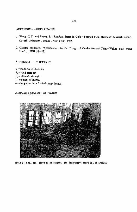
Photo I Is the roof truss after failure, the destru.ctlve chord C2( Is arrowed
414
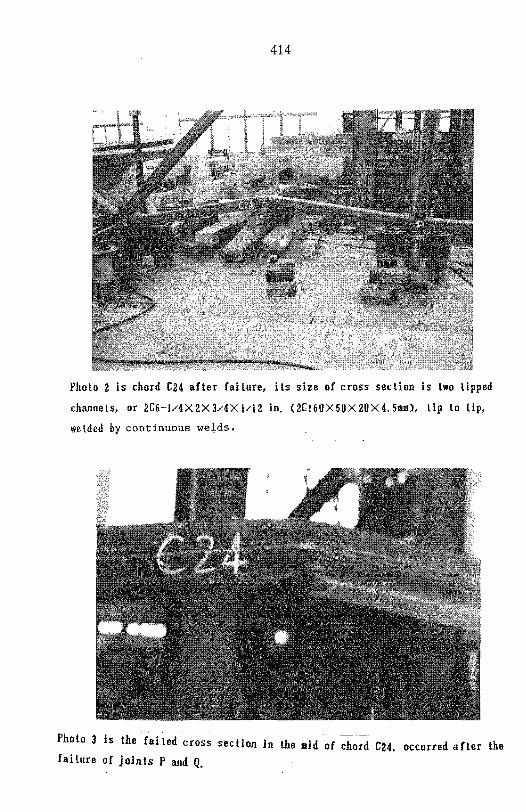
Photo 2 is (hord &24 after failure, its size of cross se(tion is two lipped
channels, or 2Cfi-l/4X2X3/4Xl/12 in. <2C16I1X50X20X4.5u), Lip to lip,
we lded by continuous we!ds.
Photo 3 Is the failed 'cross section in the aId of chord &24. occurred after the f ai lure of join ts P and Q.
415
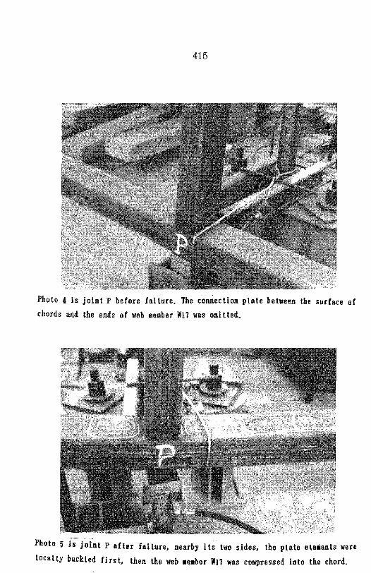
Photo 4 is joint P before failure. The connection plate between the surface of
chords and the ends of web member WI? was omitted.
Photo 5 i;-'j~int Palter failure, nearby its two sides, the plate eleMents were
locally buckled first, then the web .€laber lVI? was compressed into the chord.
416
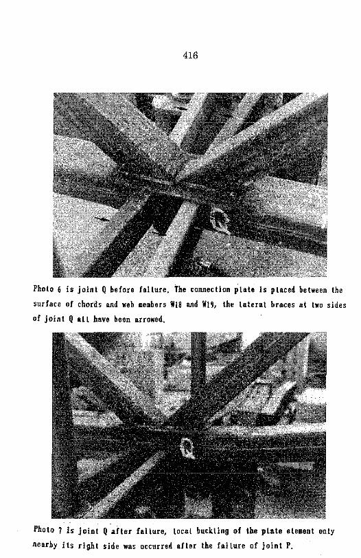
Photo 6 is joint Q before failure. The connection plate is placed between the
surface of chords and web members 118 and WI', the lateral braces at two sides
of joint Q all have been arrowed.
Photo 7 Is joint Q after failure, local buckling of the pl~te ele.ent only
nearby its right side was occurred after the failure of joint P.