insulated roof systems - nyserda
TRANSCRIPT

EXISTING FIRESTONE'S EPDMROOF SYSTEM (ASSUMED 2"OF EXISTING, MECHANICALLYATTACHED POLYISO ROOFINSULATION;AGED R-VALUE=R-10 (+/-)
5" WIDE COVER STRIPSOVER THE EXISTING LAP SEAMS
DRAINAGE LAYER(CARLISLE'S CCW MIRADRAING4 DRAINAGE COMPOSITE)DRAINAGE LAYER
(AT A RATE OF 10-12 LBS/SF)
(TOTAL THICKNESS OF FLATXPS INSULATION IS 6" (R-5 PER 1")R-30 TOTAL
NOMINAL 1 1/2" ROUNDED WATER-WORN GRAVELCONFORMING TO GRADATION #4PER ASTM D 448
NOTE:A LICENSED STRUCTURAL ENGINEER NEEDSTO PERFORM THE NECESSARY STRUCTURALCALCULATIONS TO ASCERTAIN IF THE EXISTINGROOF DECK STRUCTURE IS CAPABLE OFSUPPORTING THE PROPOSED ROOF ASSEMBLY.
BY:ELVEDIN KRUPICSWBRDEC. 19, 2018
EXISTING SLOPED WOODROOF DECK STRUCTURE

Section Overview
PRMA, Vegetative and Plaza DeckInsulated Roof Systems
PRMA, Vegetative and Plaza Deck Waterproofi ng
Protected roof membrane assemblies (PRMA) provide high value and long term durability on long life cycle buildings. PRMA roofs range in function from infrequently accessed stone ballasted systems, to paver/plaza deck walking surfaces, to fully landscaped vegetative roof gardens. PRMA extends the life of roofi ng components and reduces building maintenance costs by eliminating UV exposure and minimizing thermal cycling.
Vegetative roofs are gaining widespread acceptance due to the practical, fi nancial, and environmental benefi ts they provide. In addition to creating more usable landscaped space in the form of rooftop terraces, walkways, plazas and gardens, a well insulated PRMA vegetative roof assembly improves energy effi ciency and reduces heating and cooling costs. In some instances vegetative roofs receive fi nancial funding incentives from government agencies responsible for reducing environmental impact. Vegetative roofs provide a number of important environmental benefi ts such as reduced storm water runoff and sewer fees, they help keep contaminants out of lakes and streams, they reduce the urban heat island effect, and they improve air quality by converting carbon dioxide to oxygen.
FOAMULAR® Extruded Polystyrene (XPS) Insulation for PRMA
FOAMULAR® XPS insulation products 404, 604, 404RB and 604RB are used in PRMA applications. Extruded polystyrene is the only insulation used in PRMA roof systems due to its excellent resistance to water absorption compared to any other type of rigid board insulation. Because the insulation is installed above the waterproofi ng membrane and is exposed to water through its service life, resistance to water while maintaining physical properties is critical.
FOAMULAR® 404 and 604 have channels cut into the bottom edges on all four sides of the board to enhance drainage at the board/membrane interface. FOAMULAR® 404RB and 604RB have ribs cut into the top surface of the board in addition to the channels on the bottom. The ribs serve as drainage enhancement under pavers when the pavers are laid directly on top of the foam board.
PRMA, Vegetative and Plaza Deck Above Deck Roof Insulation
Vegetated Waterproofi ng System
Plaza Deck/Paver Waterproofi ng System
Stone Ballasted Waterproofi ng System

Section Overview
PRMA, Vegetative and Plaza DeckInsulated Roof Systems
OWENS CORNING INSULATING SYSTEMS, LLCONE OWENS CORNING PARKWAYTOLEDO, OHIO 43659
1-800-GET-PINK®
www.owenscorning.com
Printed in U.S.A. September 2011. THE PINK PANTHER™ & ©1964-2011 Metro -Goldwyn-Mayer Studios Inc. All Rights Reserved. The color PINK is a registered trademark of Owens Corning. ©2011 Owens Corning.
Disclaimer of Liability Technical information contained herein is furnished without charge or obligation and is given and accepted at recipient’s sole risk. Because conditions of use may vary and are beyond our control, Owens Corning makes no representation about, and is not responsible or liable for the accuracy or reliability of data associated with particular uses of any product described herein. Nothing contained in this bulletin shall be considered a recommendation.
The GREENGUARD INDOOR AIR QUALITY CERTIFIED mark is registered certifi cation mark used under license through the GREENGUARD Environmental Institute.
LEED is a registered trademark of the U.S. Green Building Council.
Sustainability
Owens Corning is committed to driving sustainability through greening our operations, greening our products and accelerating energy effi ciency in the built environment. Owens Corning FOAMULAR® XPS products are GREENGUARD Indoor Air Quality Certifi ed® and GREENGUARD Children and Schools Certifi edSM. FOAMULAR® XPS is also third party certifi ed, to contain a minimum 20 percent recycled polystyrene content and is produced with a zero ozone depletion blowing agent formulation. FOAMULAR® XPS insulation products contribute to achieving credits in multiple LEED® categories including energy effi ciency and recycled material content and carry a lifetime limited warranty1 on all ASTM C578 physical properties for true long lasting value.
Notes
1. See actual warranty for complete details, limitations and
requirements.

PRINCIPLES OF DESIGNING PLAZA
WATERPROOFING SYSTEMS
BY PAUL BUCCELLATO, AIA, RWC, FASTM HENSHELL & BUCCELLATO, RED BANK, NJ
S YM P O S I U M O N BU I L D I N G E N V E L O P E T E C H N O L O G Y • N O V E M B E R 2007 BU C C E L L AT O • 9

ABSTRACT
Plaza waterproofing differs from that of roofing systems because of the severe conditions under which it must perform. The waterproofing membrane is inaccessible for repairs, and its primary performance criteria are to resist the passage of water under continuous exposure to moisture. A plaza waterproofing system is covered by a wearing surface that can impede drainage at the membrane level. This makes any investigation and repair extremely difficult and expensive. Therefore, the anticipated service life of the membrane must approximate the predicted life of the building.
This paper will present design and installation fundamentals for plaza waterproofing systems. It will discuss drainage, insulation, waterproofing, and flashing details.
SPEAKER
PAUL BUCCELLATO, AIA, RWC, FASTM — HENSHELL & BUCCELLATO, RED BANK, NJ
PAUL BUCCELLATO is a registered architect in four states and holds a certificate from the National Council of Architectural Registration Boards. He is also a Registered Waterproofing Consultant with RCI. Buccellato is a member of the American Institute of Architects, the New Jersey Society of Architects, the Construction Specifications Institute, RCI, and ASTM Committees D08 Roofing and Waterproofing (chairman Subcommittee D08.20 Roofing Membrane Systems), C 15 Masonry Units, and C24.
Mr. Buccellato has authored several technical papers on waterproofing and roofing, as well as three ASTM standards on roofing, and has lectured at Brookdale College, NJ. He wrote a column on roof design for The Roofing Specifier and is coauthor of an NCARB monograph on builtup roofing. He has presented papers relating to waterproofing and roofing for RCI and ASTM.
Mr. Buccellato is a member of the RCI Education Committee and NRCA’s Educational Resource Committee. He is also a member of RCI’s Registered Waterproofing Examination Development Subcommittee.
10 • BU C C E L L AT O S YM P O S I U M O N BU I L D I N G E N V E L O P E T E C H N O L O G Y • N O V E M B E R 2007

PRINCIPLES OF DESIGNING PLAZA
WATERPROOFING SYSTEMS
INTRODUCTION The design of a plaza over occupied
space must create a system that waterproofs and insulates the structural building deck while supporting pedestrian and/or vehicle traffic, including landscaping elements (Figure 1). Its design entails multiple component layers, including a waterproofing membrane, protection layer, drainage course, insulation, and wearing surface.
Earlier plaza designs did not incorpo
Figure 1A and 1B – Plaza with landscaping elements.
rate a drainage layer within the system components. As a result, water that was trapped between the membrane and wearing surface caused them to deteriorate from freeze/thaw cycling or saturation. Since publication of Charles Parise’s seminal paper in 1981, the accepted ASTM and industry standard requires the incorporation of a drainage course. The system must allow for the flow of water from the plaza wearing surface through the various com
ponents at the drains and sides. There are two basic categories of overburden on plazas over occupied spaces:
• Hardscaping with wearing surfaces, or
• Landscaping or softscaping with planting, fountains, etc.
Systems can be further divided into categories where the membrane is either accessible or inaccessible.
Accessible systems are those in which the wearing course is removable. Pavers that are installed on insulation, pedestals, or sand beds are classified as accessible systems. Landscaping or planting is considered to be an accessible system.
Inaccessible plaza systems are those in which the membrane is covered with a concrete protection slab or where the wearing surface units are installed in a solid, mortarsetting bed. Fountains and most vehicular wearing surfaces also fall into this category. These systems require demolition of the concrete protection slab or solidly grouted units for access to the membrane.
A waterproofed plaza system that
S YM P O S I U M O N BU I L D I N G E N V E L O P E T E C H N O L O G Y • N O V E M B E R 2007 BU C C E L L AT O • 11

Figure 2 – Basic components of membrane waterproofing over a framed structural slab. (Courtesy of ASTM International.)
includes a separate wearing course contains some or all the following components (Figure 2):
• Structural deck • Membrane • Protection board or protection membrane • Drainage layer or course • Thermal insulation • Concrete protection slab (optional) • Flashing, • Wearing surface
An earthcovered system consists of essentially the same, with the exception of the wearing surface, where the earth takes its place (Figure 3).
There are three ASTM International Standards that cover waterproofing under hardscaping:
C981 — Standard Guide for Design of BuiltUp Bituminous Membrane Waterproofing Systems for Building Decks
C898 — Standard Guide for Use of HighSolids Content, Cold, LiquidApplied Elastomeric Waterproofing Membrane with Separate Wearing Course
C1127 — Standard Guide for Use of HighSolids Content, Cold, LiquidApplied Elastomeric Waterproofing Membrane with an Integral Wearing Course
Designers are advised to consult these standards when designing waterproofed plaza decks because they constitute the current body of knowledge on the subject.
STRUCTURAL BUILDING DECK A structural plaza deck typically consists of reinforced
concrete slabs, concrete topping over precast units, posttensioned slabs, or composite concreteandsteel decking. Reinforced structural concrete slabs are the most common and consist of framed or flat slabs. However, monolithic concrete slabs make a better substrate for waterproofing.
Joints between and at the ends of precast units and at
Figure 3 – Basic components of membrane waterproofing under earth.
12 • BU C C E L L AT O S YM P O S I U M O N BU I L D I N G E N V E L O P E T E C H N O L O G Y • N O V E M B E R 2007

their ends may not be in the same plane, and therefore they require a concrete topping to even out lippage and cover lifting rings and welded plates. However, the topping is prone to cracking along joints and, in particular, at the end joints, which may rotate between precast elements at supporting girders.
Posttensioned slabs offer better control of deflection and cracking within the plaza deck. However, careful analysis of the deck deflection pattern and posttensioning design is critical to achieve proper slopetodrains after the plaza overburden has been placed.
Composite decking comprised of concreteonsteel centering is more commonly used for terraces at higher floor levels than for plaza design near grade level. Provisions for venting moisture from the concrete must be made if a liquid membrane is applied to the concrete surface. This is typically achieved by using a slotted steel deck or additional curing time, which can be reduced by a low cement/water ratio.
Whichever structural system is selected, the waterproofing designer should assure himself that the structural engineer is informed as to the need for positive slopetodrain. These discussions should include coordination among the waterproofing designer, landscape architect, and structural engineer to assure adequate loadbearing capacity and slab slope.
MEMBRANES Membranes for waterproofed deck sys
tems include: • Conventional builtup bituminous • Multiply modified bitumen sheets • Singleply sheets • Liquid or fluidapplied elastomers
A builtup bituminous membrane consists of alternating multiple plies of saturated felts between applications of bitumen applied onsite (Figure 4). The plies include organic felt, glass mats or fabrics, and polyester mats or fabrics as reinforcement.
Organic felts are preferred over glass. The bitumen can be asphalt or coal tar pitch. The bitumen of choice for waterproofing is coal tar pitch (ASTM D450, Type I or II) because of its selfhealing properties. Asphalt (ASTM D449) has greater water absorption than coal tar pitch and is not suitable.
The felt plies can be shingled or phased (plyonply). In a phasedtype application, moisture that penetrates through a lap leads only to the next ply and not through the entire membrane.
Except for tarred felts, membranes constructed of organic felt have not performed well when exposed to standing water. Glass fiber felts are less absorbent than organic felt, but they tend to float or sink in coal tar pitch.
Modified bitumen sheets are modified with polymers to improve the sheets’ flexibility and elasticity, as well as the cohesive strength of the bitumen. Some are self
Figure 4 – Application of a coal tar pitch waterproofing membrane.
Figure 5 – Application of selfadhering
modified bitumen membrane.
adhering sheets, laminated to a highdensity, polyethylene backing, and are often called “peelandstick” or rubberized asphalt (Figure 5). The sheets can be applied as a single or multiply waterproofing membrane system. They must be protected from ultraviolet exposure within a few weeks of application.
Modified bitumen sheets used for roofing do not perform as well when used for waterproofing membranes because of the potential for wicking of the reinforcing as endlaps. These systems are fully adhered to the concrete substrate and are sensitive to site conditions, moisture, and deck surface quality.
Singleply sheets include EPDM, butyl
S YM P O S I U M O N BU I L D I N G E N V E L O P E T E C H N O L O G Y • N O V E M B E R 2007 BU C C E L L AT O • 13

rubber, KEE, and PVC. Butyl rubber sheets have an advantage over EPDM sheets because of their lower moisture absorption. This benefit is more important for a waterproofing membrane than EPDM’s greater resistance to ultraviolet resistance. PVC sheets offer improved puncture resistance and heatwelded seams.
These sheets are either fully adhered or loose laid. When loose laid, they should be compartmentalized by adhering the sheet in a 3meter (10foot) grid. This forms compartments that confine water migration if a leak occurs and also helps facilitate leak detection (Figure 6).
Liquidapplied membranes include hot and cold:
• Polymermodified asphalt • Singleblown asphalt • Coal tar modified urethane • Twocomponent urethanes • Aliphatic polyurethanes • Reinforced liquid polyester • Twocomponent synthetic
rubber • Polymermodified asphaltic
emulsion.
Proper performance of solvated or emulsiontype membrane systems requires that they contain a minimum of 65 percent solids to reduce pinholing. Problems associated with reflective cracking from the deck below can be addressed by proper dry mil thickness of the membrane (which is normally a minimum 60drymil film thickness) and by reinforcement
The advantage of adhered mem
14 • BU C C E L L AT O
Figures 8A and 8B – Hotapplied membrane application.
S YM P O S I U M O N BU I L D I N G E N V E L O P E T E C H N O L O G Y • N O V E M B E R 2007
Figure 6 – Compartmentalized installation of singleply PVC membrane.
Figure 7 – Pinholing and air bubbles in liquidapplied membrane.
brane systems is the localization of leaks. A disadvantage is the need for rigorous surface preparation of the substrate, which must be dry an dustfree, with a lightly broomed texture. Cracks must be detailed. Liquidapplied membranes should never be used to fill or level surface irregularities.
Moisture is the adversary of these systems. It causes urethanes to foam and hotapplied systems to froth. Dust can cause pinholing or entrained air bubbles in the coating film (Figure 7). Unsuitable curing agents such as waterglass can inhibit adhesion.
Hotapplied liquid systems are often reinforced with polyester or woven glass (Figure 8). This process requires two applications in order to prevent coincident pinholing and
thin spots in the membrane. Coldapplied liquid membranes are
applied over concrete substrates by spray, squeegee, roller, brush, trowel, or other

Figure 9 – Squeegee application of coldapplied liquid membrane.
method acceptable to the membrane manufacturer (Figure 9). Manufacturers claim that these products are sufficiently elastic to bridge cracks that occur in the concrete after the coating is in place. Reflected cracking is reduced by increased thickness.
The reinforced liquid polyester systems require exposure to ultraviolet light to cure. PMMA cures from contact with moisture in the air.
ASTM International Standard C836, which was first published in 1976, is a nongeneric performance specification that describes the required properties and test methods for coldapplied, elastomerictype waterproofing membranes for both one and twocomponent systems.
PROTECTION BOARD
Waterproofing membranes all require protection during construction as well as from ultraviolet radiation. This protection should be applied as soon as
possible after the membrane is installed and flood testing is concluded.
The industry’s most common material is an asphaltcore, laminated panel with polyethylene film on one side that prevents sticking. The panel or board is produced in
1.5mm (1/16inch), 3.1mm (1/8inch), or 6mm (1/4inch) thicknesses. One manufacturer produces a 2mm (.085inch), synthetic, fiberreinforced, rubberized, asphaltprotection sheet in roll form for use with its waterproofing system.
Protection of the horizontal waterproofing membrane is mandatory after the membrane is installed and water testing is completed. The sequencing of these steps – membrane application, flood testing, and protectionboard installation – must continue without interruption. If the protectionboard installation is delayed, damage to the waterproofing membrane can occur from some of the following construction activities (Figure 10):
• Pipe scaffolding without proper protection
• Stockpiled masonry • Reinforcing bars • Welding rods • Fasteners • Loose aggregate
Any of the above items are hazards to the membrane’s service life. A membrane is worthless after it is damaged or destroyed by careless construction operations. That is why it is important to have a qualified per
Figure 10 – Construction activities over protection board. S YM P O S I U M O N BU I L D I N G E N V E L O P E T E C H N O L O G Y • N O V E M B E R 2007 BU C C E L L AT O • 15

son inspect the membrane and to ensure that the protection board is installed after the flood testing is completed. If the membrane fails the flood test, the protection application must be held until the membrane is repaired and retested.
DRAINAGE DESIGN When a membrane waterproofing sys
tem is applied directly to the structural deck and then covered with a wearing surface or overburden, it is assumed that water will reach the membrane. If this were not the case, there would be no need for the membrane.
According to ASTM C981, drainage of the waterproofed deck system should include all components, from the wearing surface down to the membrane. The structural deck and the supporting columns and walls should be properly designed to provide positive slope. Inadequate slopetodrain is a common deficiency in plaza design.
Drainage at the membrane level is required for the following reasons:
• To avoid building up hydrostatic pressure due to collected water against the membrane
• To avoid freezethaw cycling of trapped water that could heave and disrupt the wearing surface
• To minimize the harmful effect that standing, undrained water may have on the wearing surface material and membrane
• To minimize thermal inefficiency of wet insulation or water below the insulation
A 2 percent (6mm 1/4in per ft) slope is recommended for positive drainage. The substrate should slope away from expansion joints and walls. Gravel or plastic drainage panels (Figure 11) and grooved or ribbed insulation boards can provide the necessary medium to facilitate water flow to drains.
Waterproofed decks should incorporate multilevel drains capable of draining all layers (Figure 12). These drains must permit differential movement between the strainer located at the wearing level and the drain body that is cast into the struc
tural concrete slab to prevent shearing. The drainage of a waterproofing system
at the wearing surface level can be accomplished through an openjointed or closedjointed system. The openjointed system allows rainwater to quickly filter down to the membrane level and subsurface drainage system. A closedjointed system is designed to remove most of the rainwater rapidly by sloping surface drains and allowing a minor portion to gradually infiltrate down to the membrane level.
Openjointed systems include pavers on pedestals or pavers placed directly on ribbed polystyrene insulation boards (Figure 13). Joints should be less than 6 mm (1/4in) wide to minimize catching highheels and cigarettes. Advantages are:
• El imina tion of the cost and ma i n t e nance of s e a l a n t joints
• Ease of adaptability to a deadlevel wearing surface
• Faster and more efficient drainage • Easier access for cleaning and
repairs to subsurface components
The disadvantages are: • Rocking of improperly set pavers
due to pedestrian traffic • Unpleasant reverberations from heel
impact • Possible hazards for pedestrians
wearing highheeled shoes
Figure 11 – Plastic drainage panel.
Figure 12 – Twostage plaza drain. (Courtesy of ASTM International.)
16 • B U C C E L L AT O S YM P O S I U M O N BU I L D I N G E N V E L O P E T E C H N O L O G Y • N O V E M B E R 2007

Closedjoint systems consist of either a • Its imposition of a
Figure 13 – Openjointed pavers on pedestals.
mortarsetting bed or caulked joints. This type of construction changes the waterproofing membrane to a secondary line of waterproofing defense, since the majority of rainwater is drained from the wearing surface level (Figure 14). The closedjoint system should slope away from adjoining walls and expansion joints to direct water away above and below the wearing surface level. The advantages of a closedjointed system include:
• Protection of the membrane from deicing chemicals, dirt, and debris
• Its flexibility to a greater variety of paver types, designs, and sizes
• The feeling of solidity under pedestrian traffic
The main disadvantages are: • Its slow drainage rate
Closedjoint pavers over mortarsetting bed. S YM P O S I U M O N BU I L D I N G E N V E L O P E T E C H N O L O G Y • N O V E M B E R 2007
hydrostatic head of pressure on the membrane.
A third system that is better than a closedjointed system, but not as good as an openjointed system, is one that provides for brick or stone pavers in a sandsetting bed.
INSULATION The selection of insulation and its loca
tion in the system is influenced by:
• Deck design • The environ
ment under which it may be functioning
• Its physical and chemical prop
Figures 14A and 14B –
erties • The characteristics of the wearing
surface • The loads to be supported
Insulation placed over the waterproofing membrane, protection, and drainage layer results in maximum system benefit. When insulation is placed in this location, the deck and membrane are insulated against
BU C C E L L AT O • 17
extreme temperature cycles and the membrane can then function as a vapor retarder. The location of the insulation above the membrane also provides additional protection to the membrane.
The choice of insulation type is limited to extruded polystyrene (XPS) (ASTM International C578 Standard Specification for Rigid, Cellular Polystyrene Thermal Insulation). It must be able to accommodate the plaza’s dead and live loads and be dimensionally stable and compatible with the waterproofing membrane. It must also be as nonabsorbent as possible and resistant to freeze/thaw deterioration
FLASHING AND EXPANSION JOINTS Waterproofed deck systems, like roof
systems, require flashings where the membrane terminates at walls, penetrations, and expansion joints. However, unlike roof systems where the flashing installation follows the membrane installation, flashing waterproofed deck terminations or penetrations must be installed first, prior to the membrane application.
FLASHING INSTALLATION
Reinforce all intersections that occur at walls, corners, or any other location that may be subjected to unusual stress with one additional ply of membrane.
Extend flashing membranes above the wearing surface a minimum of 100 mm (8 in). This height is critical if the plaza design incorporates a wearing surface with closed joints. When the flashing extends above the wearing surface, it must be covered or protected against exposure to ultraviolet sunlight with sheet metal or vertical wall finishes such as stone or stucco. Some liquidapplied membranes (LAM) are self flashing.
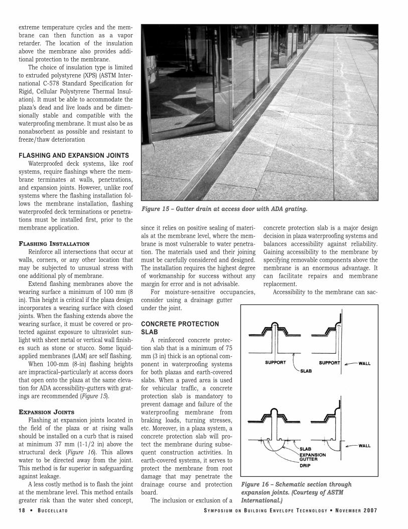
When 100mm (8in) flashing heights are impractical–particularly at access doors that open onto the plaza at the same elevation for ADA accessibility–gutters with gratings are recommended (Figure 15).
EXPANSION JOINTS
Flashing at expansion joints located in the field of the plaza or at rising walls should be installed on a curb that is raised at minimum 37 mm (11/2 in) above the structural deck (Figure 16). This allows water to be directed away from the joint. This method is far superior in safeguarding against leakage.
A less costly method is to flash the joint at the membrane level. This method entails greater risk than the water shed concept,
Figure 15 – Gutter drain at access door with ADA grating.
since it relies on positive sealing of materials at the membrane level, where the membrane is most vulnerable to water penetration. The materials used and their joining must be carefully considered and designed. The installation requires the highest degree of workmanship for success without any margin for error and is not advisable.
For moisturesensitive occupancies, consider using a drainage gutter under the joint.
CONCRETE PROTECTION SLAB
A reinforced concrete protection slab that is a minimum of 75 mm (3 in) thick is an optional component in waterproofing systems for both plazas and earthcovered slabs. When a paved area is used for vehicular traffic, a concrete protection slab is mandatory to prevent damage and failure of the waterproofing membrane from braking loads, turning stresses, etc. Moreover, in a plaza system, a concrete protection slab will protect the membrane during subsequent construction activities. In earthcovered systems, it serves to protect the membrane from root damage that may penetrate the drainage course and protection board.
The inclusion or exclusion of a
concrete protection slab is a major design decision in plaza waterproofing systems and balances accessibility against reliability. Gaining accessibility to the membrane by specifying removable components above the membrane is an enormous advantage. It can facilitate repairs and membrane replacement.
Accessibility to the membrane can sac
Figure 16 – Schematic section through expansion joints. (Courtesy of ASTM International.)
18 • BU C C E L L AT O S YM P O S I U M O N BU I L D I N G E N V E L O P E T E C H N O L O G Y • N O V E M B E R 2007

rifice reliability. Protection boards and drainage composite boards can provide resistance to root intrusion for earthcovered slabs. However, they can neither provide the level of resistance to root intrusion that a concrete protection slab can nor the protection from landscaping equipment. The decision to incorporate a concrete protection slab must be based on cost, which includes the initial cost of the slab and the potential cost associated with its removal to access the waterproofing membrane.
WEARING COURSE As stated previously,
wearing surfaces are generally divided into openjoint systems that are drained at the membrane level and closedjoint systems that are drained at the surface.
Waterproofing membranes in an openjoint system are infrequently subjected to hydrostatic pressure exceeding 5 psf (25 mm [1 in] depth of water). Closedjoint systems shed water at the surface and similarly protect the membrane from hydrostatic pressure.
Any waterproofed plaza wearing surface must satisfy and meet the following criteria:
• Structurally sound to bear the intended traffic
• Durable under heavy wear and weathering
• Resistant to abrasion • Aesthetically pleasing • Heat reflecting
The first two items are mandatory, and the last two are optional.
EARTHCOVERED SLABS Although beyond the scope of this
paper, earthcovered slabs can be planted with groundcover, shrubs, and trees. Typically referred to as a green roof system, it is an extension of the existing roof that involves a highquality waterproofing and root barrier system, a drainage system, filter cloth, a growing medium, and plants.
Green roof systems may be modular, with drainage layers, filter cloth, growing media, and plants already prepared in movable, interlocking grids; or each component
Figure 17 – Planter containers.
of the system may be installed separately. A green roof involves the creation of “contained” green space on top of a manmade structure.
In today’s environment, building owners and architects are embracing green roof technology. The two distinct types of green roofs are intensive and extensive.
Extensive green roofs are much lighter in weight, with engineered soil depths ranging from 75 mm (3 in) to 175 mm (7 in). Due
to the shallow soils and the extreme environment on many roofs, plants are typically lowgrowing groundcover that are extremely sun and drought tolerant.
Extensive green roofs can be installed over existing roof decks, provided a structural engineer first inspects the structure to ascertain its load capacity. Although the focus of most extensive green roofs are their environmental benefits, extensive green roofs still require periodic maintenance and must be designed to resist wind uplift.
Intensive green roofs are characterized by thick soil depths (200 mm [8 in] 1.2 m [4 ft]), heavy weights, and elaborate plantings that include shrubs and trees. Intensive green roofs are installed primarily over concrete roof decks to withstand the weight requirements. These parklike green roofs can be at or above grade and require considerable maintenance to sustain their aesthetic appearance.
PLAZA FURNITURE If a plaza design includes planters,
reflecting pools, foundations, benches, and
S YM P O S I U M O N BU I L D I N G E N V E L O P E T E C H N O L O G Y • N O V E M B E R 2007
other plaza “furniture,” they should be installed over the waterproofing membrane. These items should be waterproofed individually and not part of the main waterproofing membrane. Trees should be planted in concrete containers (Figure 17) to avoid damage to the waterproofing membrane from root penetration or landscape shovels.
FLOOD TESTING A failed waterproofing system is more
destructive and expensive to correct than a failed roof. The replacement cost of a failed roof can be anywhere from $15 to $22 psf; a failed waterproofed plaza, between $75 and $125 psf, at a minimum.
It is therefore advisable to floodtest a waterproofed deck after the flashing and membrane have been installed. ASTM D5957, Flood Testing Horizontal Waterproofing Installations, first published in 1996, provides the necessary method for testing the watertightness of a waterproofed deck (Figure 18). Some limitations
of this standard are: • Slopeofdeck or membrane to be
tested must not exceed 2 percent (6.25 mm [1/4 inch]) per foot.
• Membranes can be LAMs, adhered or looselaid sheets, or builtup and modified.
• Do not test until 24 hours after the membrane has been installed. (This requirement increases to 48 hours if the membrane was installed at ambient temperatures below 50˚ F.)
• Inspect and repair flashing and membrane prior to testing.
If a leak occurs during the test process, the following provisions are to be followed:
• Drain water. • Locate and repair leak. • Retest area under the same initial
conditions.
Electric field vector mapping (EFVM™) is a new tool for improving quality control of waterproofing systems. Although relatively new to the United States, it has achieved a
BU C C E L L AT O • 19

long record of success in Europe. The system was pioneered in Germany. EFVM, unlike other leakdetection methods, can quickly and accurately locate the point of water entry.
EFVM uses water as an electrically conductive medium. A wire loop is installed around the perimeter of the area to be tested and introduces an electrical potential. The area within the loop is dampened and forms the upper electrical plate. The structural deck then becomes the lower plate. The membrane acts as separator and insulator between the two plates. If moisture enters a defect in the membrane, an electrical contact is established. The survey technician can then follow the direction of the electric field to the membrane defect. Advocates of EFVM state that the test method:
• Locates defects precisely, enabling efficient repairs
• Is able to retest repairs immediately • Can be used after cover systems are
installed, especially with green roof landscapes
• Is less expensive than conventional flood testing
• Eliminates the hazard of overloading structural decks during testing
• Can be used on steeply sloped roof surfaces where flood testing is impossible
The suitability of EFVM depends on the electrical resistance of the waterproofing materials, and all membranes may not be compatible with this test method. Systems that employ a root barrier require special procedures, since the root barrier will act as an insulating layer. When root barriers are used, it is necessary to make small slits in the barrier to permit the establishment of electrical contact with the underlying waterproofing membrane. These cuts can be resealed after the leak is located.
SUMMARY A plaza design over occupied spaces
must create a system that waterproofs and insulates the structural building deck while supporting pedestrian and/or vehicle traffic, as well as landscaping elements.
The building deck must be reasonably smooth, be sound, and provide adequate slope to promote drainage. The waterproofing membrane selected and installed must be capable of withstanding longterm exposure to ponding water. Flashings at drains, penetrations, expansion joints, and other similar membrane terminations should be carefully detailed, since most leakage problems occur at these locations.
Insulation should be placed above the membrane to minimize temperature cycles of the membrane and deck and provide additional protection for the membrane. The insulation must have high compressive strength, low water absorption, and be resistant to freeze/thaw.
Drainage at the membrane level is an essential component of the system. Drainage at both the membrane level and below the wearing surface is particularly important to ensure water flow to drains and minimize freeze/thaw heaving or deterioration of the wearing surface.
The wearing surface should be aesthetically pleasing, durable, and able to accommodate loads associated with the plaza function. The wearing surface should consist of discrete components to facilitate
removal and reinstallation and to allow for maintenance.
BIBLIOGRAPHY Buccellato, Paul, “BelowGrade Water
proofing Selection Process,” 2006 Building Envelope Technology Symposium, Washington, D.C., RCI, Inc.
Buccellato, Paul, “Principles for Better Waterproofing,” 2002 Building Envelope Technology Symposium, Coral Springs, FL, RCI, Inc.
Henshell, Justin, The Manual of BelowGrade Waterproofing Systems, 2000, John Wiley & Sons, Inc., New York, NY.
Kubal, Michael K., Waterproofing the Building Envelope, McGrawHill, Inc. New York, NY.
Parise, Charles, Waterproofing Structural Concrete Decks over Occupied Space, 1981, American Concrete Institute’s SP70.
Simpson, Gumpertz & Heger, The Building Envelope: Solutions to Problems.
2 0 • B U C C E L L A T O S Y M P O S I U M O N B U I L D I N G E N V E L O P E T E C H N O L O G Y • N O V E M B E R 2 0 0 7
Figures 18A and 18B – Flood testing. (Sketch courtesy of ASTM International.)

SarnafilPlaza Deck Systems

Waterproofing. Protect your investment.
You are an architect, a designer or a building
owner, and you have a building to protect.
If this building is like most, it has critical areas
inside the building that must be protected
from the damaging effects of water, moisture
or other contaminants. If these areas are
covered with overburden such as earth,
landscaping and pavers, it can be a challenge
to remove the overburden and determine the
cause should a leak occur. As a result, one
of the most important decisions you have to
make is the waterproofing system.
Without proper waterproofing it is a question
of when, not if, water infiltrates the structure.
Structures move and settle with time.
Structural movements or deficiencies cause
cracks and openings in the structure.
The cracks and openings create a pathway
for water and moisture to enter the building.
Water infiltration not only affects the usage
and value of a building, but also has the
potential to propagate mold and fungus
growth. A building owner can be faced with
future repairs and mitigation actions that
could cost thousands. Because of this, it is
important to not only waterproof your building,
but to choose a waterproofing manufacturer
whose performance history speaks for itself.
Sika Sarnafil. Waterproofing integrity.
Sika Sarnafil has earned the reputation as
the most trusted name in waterproofing.
Architects, specifiers and building owners
choose Sika Sarnafil waterproofing systems
for applications that demand absolute
system integrity and watertight security.
For over 40 years our waterproofing systems
have provided protection against water
infiltration on many of the world’s most
valuable building and civil engineering
structures. With over 15 billion square feet
of roofing and waterproofing membrane
installed worldwide, you can depend on
Sika Sarnafil for proven products and
system performance.
Sika Sarnafil manufactures a variety of
thermoplastic waterproofing membranes
designed to provide long-term durability
and watertightness for varying building
and civil engineering applications and
conditions. Our Sarnafil G476 membrane
is the key component to the success of
our waterproofing systems.
Sika Sarnafil has been using the same
basic formulation in its manufacturing
process for over 40 years. This durable
thermoplastic membrane is designed to
remain watertight in the extreme conditions
of buried environments including constant
dampness, ponding water, high and low
alkaline conditions, exposure to plant roots,
fungi and bacterial organisms.
Sarnafil G476 membrane is available
in a range of thicknesses to match the
application, overburden type and your
specific project requirements. Highly
puncture resistant, its bright orange surface
color makes it easy to identify and inspect to
maintain high levels of quality assurance and
control during construction.
s JFK Library and Museum, Boston, MA
Sarnafil Milestone Management
The Sarnafil Milestone Management™
process is the key to a successful
installation. From specification
assistance to installation, our “hands
on approach” is designed to make
any project an easier task for you.
Here’s how we help make the process
go smoothly:
Proven Materials
A high quality membrane is the key to
any successful roofing or waterproofing
project that demands absolute system
integrity. With that in mind, Sika Sarnafil’s
manufacturing process uses only the
highest quality materials to produce a
monolithic, non-laminated membrane
that offers excellent weatherablility and
dimensional stability.
Expert Assistance
Our skilled technical experts make
Sika Sarnafil stand apart from other
manufacturers. We’re involved at each
major milestone – offering design
assistance to architects and specifiers
if needed, reviewing Notice of Award
documentation, and training authorized
applicators in the classroom and at
the job site.
Skillful Workmanship
Unlike most other roofing and water-
proofing manufacturers, Sika Sarnafil
does not sell through distributors.
Instead, we sell directly to a select group
of trained, authorized applicators – only
the best are invited to join our team.
Maintaining strict control over
the installation process means that
Sika Sarnafil quality is carried through
from start to finish.On the cover:
H.H. Dow Academy
Midland, MI
s

Plaza Deck Waterproofing
Plaza decks are located at or above grade
level. They are public areas accessible to
pedestrians and in some cases vehicles.
They may cover valuable commercial or
office space, storage or mechanical areas,
or parking.
Plaza decks are waterproofed to protect
the structure, their occupants and the
property beneath them from water and
moisture penetration.
Plaza decks require special attention since
they may hold water for a period of time
after precipitation, and the waterproofing
system is buried under the overburden
making repairs challenging and costly.
Choosing the right waterproofing system
is one of the most important decisions you
will make on your project.
The right waterproofing system should:
Provide Factory Controlled Membrane
Thickness – Sheet waterproofing
membranes are manufactured in a
controlled environment, eliminating
thickness variations found in field-
applied systems. Thin spots can lead
to a premature failure in the water-
proofing system.
Accommodate Building Movement –
Waterproofing systems need to be
flexible enough to withstand structural
and thermal movement, and versatile
enough to provide design options for
each application.
Perform in Ponded Water Conditions –
Decks will hold water. The waterproofing
membrane must withstand ponded water
and constant damp conditions.
Resistant to Roots and Decay – Roots are
very aggressive and can penetrate some
types of waterproofing materials. The
waterproofing system must be resistant
to roots and should not deteriorate in
damp environments.
Puncture Resistance – Waterproofing
membranes must be tough and highly
puncture resistant to withstand potential
damage during and after installation.
Protection layers will provide protection,
but there will be times during the
construction process when the water-
proofing membrane will not be covered.
Secure Seams – Sheet membranes are
seamed together in the field to form
a continuous waterproofing barrier.
The seams must be the strongest part
of the system, not the weakest.
Proven Performance History – Make sure
the company behind the waterproofing
system has a history of proven
performance on projects similar to yours.
Sika Sarnafil waterproofing systems meet
and exceed these requirements. Sarnafil
G476 membrane provides long-term durability
and high puncture resistance. This durable
thermoplastic membrane is compounded
to remain watertight in extreme conditions
including constant dampness, ponded water,
high and low alkaline conditions, exposure
to plant roots, fungi and bacterial organisms.
It also is extremely flexible and able to
conform to even the most difficult of details.
Sarnafil membrane seams are hot-air
welded, a key factor to the success of our
waterproofing systems.
s Chase Tower Plaza, Dallas, TX

Adhered SystemWhen your building demands absolute
system integrity with maximum watertight
security, Sika Sarnafil’s adhered system is
for you. The system consists of the robust
G476 Self-Adhered (SA) membrane, a
composite sheet comprised of the heat-
weldable G476 waterproofing membrane
with a closed-cell foam backing. The foam
backing is factory-coated with a pressure
sensitive adhesive and is protected by a
plastic release liner which is removed
during installation.
Sarnafil G476 SA combines the time-tested,
proven performance of Sarnafil G476 water-
proofing membrane with the added security
of an adhered sheet system. G476 SA
provides ‘peace of mind’ for specifiers and
owners who value the benefits of an adhered
system and thermoplastic technology.
The flexible foam backing layer conforms
to minor irregularities in the substrate and
provides a cushion for the G476 waterproofing
membrane. The pressure sensitive adhesive
provides a tenacious bond to the substrate
mitigating potential water migration under
the membrane. The integration of G476
membrane with a foam backing layer and
pressure sensitive adhesive eliminates the
need for a field installed separation layer
and adhesives. This ‘all-in-one’ product
increases applicator productivity and helps
keep the project on schedule. Sarnafil G476
SA also doesn’t require hot asphalt kettles or
flammable adhesives. This improves worker
and job site safety.
Sarnafil G476 SA is best suited for new
construction. It can also be used on
certain renovation projects where the old
waterproofing system can be removed
completely, or where a new concrete topping
slab is placed over the structural deck.
Advantages:
Robust, factory-manufactured
composite sheet
Mitigates water migration under
the sheet
Reduces the risk of expensive removal
and replacement of overburden
Heat-weldable laps
More Sika Sarnafil Benefits
Grid SystemFor renovation projects where the substrate
is contaminated or removal of the existing
waterproofing is not practical, Sika Sarnafil
offers the grid system. The grid system
combines all of the advantages of a loose-
laid membrane installation with the added
security of adhered membrane grid strips.
The grid strips compartmentalize the water-
proofing system into smaller areas effectively
limiting the scope of overburden removal if
a problem develops.
Advantages:
The adhered grid strips act as a sub-
membrane waterstop to compartmentalize
the waterproofed areas and limit over-
burden removal if a problem develops
Optional control drains can be installed in
each grid area as an active monitoring and
alerting mechanism. The drain opening can
be used as an injection port to facilitate
repair without overburden removal
The grid system can be installed
economically over existing waterproofing
with minimal deck preparation and removal
of the existing waterproofing system
s St. Louis Children’s Hospital, St. Louis, MO
Quality Assurance
Quality assurance is the key to a successful
project. Sika Sarnafil offers on-site monitoring
and inspection programs to building owners
who want active involvement from the water-
proofing system manufacturer. Sika Sarnafil
has nearly 50 years experience in water-
proofing applications and can assist the
owner in achieving maximum performance.
Root Resistance
Many waterproofing membranes are not
resistant to root penetration. They fail,
often prematurely, due to root infiltration
into the field seams and flashings.
Our Sarnafil membranes are inherently
root and algae resistant and do not require
additional root barriers. Sarnafil membranes
have passed the most stringent European
tests for root resistance including both
the German FLL and the Swiss SIA 280
standards. The FLL standard test exposes
the waterproofing membrane to 2 years
of accelerated root growth.
G476 SA Composite Membrane – Cross SectionG476 with Heat Weldable Selvedge
Closed Cell Foam Backing
Pressure Sensitive Adhesive
Removable Release Liner
Hot-Air Welded Seams and Flashings
Faulty seams and details are a common
source of leaks in waterproofing systems.
Some waterproofing membranes use sealants,
adhesives or tapes to secure the seams, but
because the Sarnafil membrane is thermoplastic,
seams and flashings are welded together using
Sika Sarnafil’s automatic hot-air welder, the
Sarnamatic. When welded together, the sheets
of membrane become one monolithic layer
of material impervious to water and moisture
infiltration. In fact, hot-air welded seams are
even stronger than the membrane itself and
will last at least the duration of the system.
Warranty Options
Sika Sarnafil offers two types of warranties,
consisting of 5, 10, 15 and 20 year durations:
Waterproofing Membrane Only (Material)
Waterproofing Labor and Material (Standard)
Partners Club
Sika Sarnafil sells directly to a limited
group of authorized applicators assuring
only trained, qualified contractors install
our systems. Every applicator is trained
on system installation and assisted as
necessary during projects by our technical
specialists. Only the best applicators are
invited to join our team, your assurance
of a quality installation.
si
ka sarnafil
qu
ality assur
ed
Paver System
Filter Fabric
Extruded Polystyrene Insulation
Drainage Composite
Protection Layer
G476 Self-Adhered Membrane
Substrate
Paver System
Filter Fabric
Extruded Polystyrene Insulation
Drainage Composite
Protection Layer
Substrate
G476 Membrane
Grid StripLeveling Layer

Sika Sarnafil
A Division of Sika Corporation
100 Dan Road
Canton, MA 02021
Telephone 1-800-451-2504
Telefax 781-828-5365
Internet www.sikacorp.com
Sika Sarnafil
A Business Unit of Sika Canada, Inc.
6820 Davand Drive, Unit 2
Mississauga, Ontario
L5T 1J5 Canada
Telephone 1-800-268-0479
Telefax 905-670-5278
Internet www.sika.ca
Sika – Your Local Partner with a Global Presence
Sika is a globally active company in the
specialty and construction chemicals
business. It has sub sidiary manufacturing,
sales and technical support facilities in
over 70 countries around the world.
Sika is THE global market and technology
leader in water proofing, sealing, bonding,
dampening, strengthening and protection
of buildings and civil engineering structures.
Sika has more than 10,000 employ ees
world wide and is therefore ideally positio ned
to support the success of its customers.
Quick Reference Guide
Sika Sarnafil Waterproofing Systems provide…
Proven performance •Anindustryveteranthathasproducedbillionsofsq.ft.ofmembrane
since 1964
•Thesamebasicmembraneformulationthathasprotectedbuildingsformore than 40 years
•Materialthatconsistentlyranksasthehighestqualitythermoplastic membrane in independent testing
Watertight integrity •Permanentwatertightflashingsanddetailswithhot-airweldedseams
•TheSarnafilG476membraneisdesignedforburiedenvironmentssuch as constant dampness, ponding water, high and low alkaline conditions,
exposure to plant roots, fungi and bacterial organisms
Milestone Management •Proven Materials – Sika Sarnafil’s manufacturing process uses only the
highest quality materials to produce a monolithic membrane that offers
excellent waterproofing and dimensional stability
•Expert Assistance – We’re involved at each major milestone, offering
design assistance to architects and specifiers if needed
•Skillful Workmanship – We sell directly to a select group of trained,
authorized applicators—only the best are invited to join our team
Our most current General Sales Conditions shall apply.
Please consult the Product Data Sheet prior to any use and processing.
ISO 14001: 2004-Compliant
081
5/5
M/1
01
0 ©
Sik
a S
arnaf
il
ed w
ith s
oy in
ks o
n st
ock
cont
aini
ng 5
5%
rec
ycle
d fib
er w
ith 3
0%
pos
t co
nsum
er c
onte
nt.

Plaza Waterproofing and Green Roofing Utilizing Liquid-applied Reinforced Polymeric MembranesReprinted with permission from Interface, The Journal Of RCI, January 2008

Plaza Waterproofing and GreenRoofing Utilizing Liquid-AppliedReinforced Polymeric Membranes
By Paul Allenstein, PE
At first glance, plaza waterproofing and green roofingmight not appear to have much in common. After all, mostplazas are at grade level or, at most, a few stories above theground, while green roofs (garden roofs, landscaped roofs,etc.) are way up on top of the building. Though theseapplications may appear opposite in concept, they end up achieving the same purpose.
Plaza waterproofing and green roofing both represent theneed and desire to achieve multiple functions from thesame space. Plazas create and allow the use of occupiedspace under an open public area. Green roofs create andallow the use of an open public area above an occupiedspace.
Relative elevations aside, plaza waterproofing and greenroofing share many of the same challenges toward achieving a watertight condition, which is the fundamentalrequirement of both applications:
• The membrane will be inaccessible following application of overburden.
• The membrane will be subjected to moist and dark conditions, with the likelihood of standing water in some areas.
• The flashings will be subjected to long-term UV exposure.
• The membrane will be subjected to foot traffic and use as a staging area during overburden placement.
• The waterproofing/roofing membrane will be expected to accommodate elevation changes,
dividing walls, planting wells, fountains and other water features, and various overburden materials.
The use of liquid-applied reinforced polymeric membranesystems allows designers and specifiers to satisfy these criteria.
Selecting the Membrane
Liquid-applied reinforced polymeric membrane is a 50-year-old technology that has only recently begun to enjoy more widespread recognition.
Briefly, liquid-applied reinforced polymeric membrane systems utilize a polymer-based resin (polyester,polyurethane, polymethylmethacrylate) to saturate a polyester or fiberglass reinforcing fabric. The advantages of this type of system are as follows:
• The reinforcing fabric is cut to fit tightly at perimeter conditions and around penetrations so that when the fabric is saturated with the resin, the flashings conform and bond directly to the walls, curbs, and penetrations. This eliminates the use of pitch pockets, preformed boots, termination bars, and other accessory products.
• Based upon laboratory testing, liquid-applied polymeric resins generally have an inherent resistance to deterioration from UV rays root penetration, and algae growth. This allows the use of the same resin and reinforcement at flashings as well as on the field membrane, providing a monolithic and continuous barrier to water penetration. This eliminates the need for the use of dissimilar flashing materials such as rubber sheets and metal accessories that can disbond from the primary waterproofing/roofing membrane. In addition, it eliminates the need for the use of a root barrier and UV barrier, typically required with asphalt-based membranes and representing an added expense to the installed system.
When the owners ofMassachusetts General Hospitalenvisioned constructing a newlandscaped green roof abovetheir cancer wing in 2005, theyhad two chief concerns: safetyand long-term durability. Theychose a cold-liquid-appliedwaterproofing and roofingmembrane by Kemper System,Inc. The landscaped roof designincluded four different gardenswith extensive shrubbery, treesand grass designed to providecancer patients with a havenfor relaxation and meditationto aid in the healing process.

• Liquid-applied polymeric membrane systems are generally durable and resistant to scuffing, puncturing, and tearing. They do not soften significantly in hot weather and retain reasonableflexibility in cold weather. A simple aggregated surface utilizing kiln-dried sand broadcast into the
wet resin will significantly improve resistance to damagerelated to foot traffic and staging operations. Of course, it is always a good idea to provide additional temporaryprotection in areas of heavy use.
• When properly installed, a polymeric membrane system provides a tightly bonded, custom-fitted membrane and flashing system that can seamlessly transition from through-wall flashing to base flashing to plaza deck membrane to parapet wall flashing to fountain lining to green roofing membrane to planter lining; all without mechanical transitions, system breaks,
material changes, or other discontinuities.
For these reasons, a liquid-applied polymeric reinforcedmembrane system is often the system of choice for plazadeck waterproofing and green roofing applications.
Selecting the System
A design consideration related to the selection ofmembrane type is the design of a basic membrane system.This involves the following considerations:
• It is usually preferable to have the waterproofing/roofing membrane fully adhered, whether it is adhered directly to the structural deck substrate or to an underlying foam insulation/cement coverboard assembly. By nature, liquid-applied polymeric reinforcedmembrane systems are always fully adhered.
• There may be some system cost savings associated with the use of grid-adhered, mechanically attached, and loose-applied membranes, because adhesives can be expensive and less labor is required if adhesives and mechanical fasteners can be eliminated entirely. However, should there be a water penetration event, with mechanically attached and loose-applied systems,
there is the certainty of uncontrolled lateral movement of water beneath the membrane. Grid-adhered systems are dependent on the integrityof their grid to provide some degree of water control. The cost savings compared to a fullyadhered system is probably not sufficient to justify
the increased risk and future expense associated withuntraceable, buried leaks.
• It is usually preferable to have the waterproofing/roofing membrane placed directly over the structural deck, which is generally possible with concrete and wood decks. Again, this minimizes the potential for lateral movement of water beneath the membrane. If insulation is required in the system, extruded polystyrene insulation can be placed above themembrane in a manner similar in concept to a typical protected membrane assembly. Wherever possible, fully adhered membranes should be installed in plaza deck waterproofing and green roofing applications.
If insulation must be installed beneath the waterproofing/roofing membrane (as is the case with steel decks), theuse of a water- and rot-resistant foam insulation suchas polyisocyanurate or extruded polystyrene isrecommended. In addition, the installation of a waterand rot-resistant, high-compressive-strength, cement-based cover board is recommended as well. In a1/2-inch thickness, cement-based coverboards actalmost like concrete decks, minimizing the potential forpenetration through the membrane and into the heartof the insulated assembly, thereby limiting the potentialfor lateral movement of water beneath the membrane.
Selecting the Overburden Assembly
Plaza decks and green roofs both lend themselves to creative selection of overburden materials to create an environment that satisfies the overall design intent. This can range from an area for quiet, private reflection to something as completely different as an area for transient, public gatherings.
Typical challenges of most applications where planters are involved arethe numerous steel reinforcing bars that project upwards through thedeck. Most systems don’t have the ability to wrap those penetrationsand treat each rebar as an individual flashing. The waterproofing androofing membrane’s ability to detail each individual rebar greatlyreduces the possibility that water will seep through the planter wallsand down to the existing plaza. This plaza is at 75 Henry Street,Brooklyn, NY.

What follows is a short listing of commonly used overburdenmaterials and some general comments on each.
Precast Concrete Pavers on Pedestals – This is the mostcommon plaza-deck wearing course. Pavers are typically24” x 24” x 2” thick. The use of a drainage mat, asphalt-protection board, or nonwoven polyester mat is often specified as protection between the pedestals and thewaterproofing membrane. Sometimes pieces of extrudedpolystyrene insulation are substituted for pedestals as acost-saving measure. This is not a good idea because thepieces of extruded polystyrene insulation tend to movearound under the pavers and do not allow for accurateshimming and adjustment of paver heights.
Precast Concrete Pavers, Natural Stone Tiles, or Brick PavingStones in a Sand Setting Bed – The use of a drainage mat is critical in order to have the sand-setting bed drainproperly. Edge securement around the perimeter, at drainoutlets, etc. is required to ensure that the paving units donot shift over time. The selection of the correct sand forthe setting bed is important. Some specifiers prefer to mix a small quantity of asphalt into the sand. The use of bilevelplaza drains is required with this type of overburden, providing drainage at both the membrane level as wellas at the overburden level.
Quarry Tile or Natural Stone Tile in a Cementitious SettingBed – The use of a drainage mat beneath the setting bed ispreferred by many specifiers as a means of ensuring properdrainage of the setting bed, reducing the potential forfreeze-thaw damage, and possibly limiting efflorescence inthe grout joints. Typically, a 2” thick cementitious settingbase bed is installed first, with the quarry or stone tile situated into a thin-set cementitious tile adhesive. The selection of a polymer-modified setting bed, tile adhesive,and grout intended for exterior application is important toachieve satisfactory performance. Interior-grade materialsshould not be used. The use of bilevel plaza drains isrequired with this type of overburden, providing drainage atboth the membrane level as well as at the overburden level.
Wood Decking on Pedestals or Sleepers – Wood decking is often installed in residential applications. The use of adrainage mat is usually specified as a protection layerbetween wood sleepers and the waterproofing membranebecause it facilitates drainage beneath the sleepers. Wooddecking is sometimes constructed in sections to allowremoval and reinstallation to provide access to the water-proofing membrane. Of interest is the recent introductionof wood deck tiles intended to be supported on pedestalscommonly used to support concrete pavers. The selectionof wood type is important; the current trend towards environmentally sensitive use of natural resources favors the use of naturally rot-resistant wood such as teak and ipâ that are part of a controlled harvesting program. Wood decking will require maintenance.
Sedum-Based Extensive Green Roofing – Many traditionalgreen roof systems use hardy, low-lying sedum plants set in2”–3” of a special growing medium. The sedum plants maynot be particularly attractive compared to flower beds,shrubs, and turf, but the sedum plants require little maintenance and provide all of the environmentally important attributes of green roofing such as drainageretention, improved localized air quality, and protection of the waterproofing membrane.
A drainage and water-retention mat is usually installedbetween the growing medium and the waterproofingmembrane. The special growing medium consists of mineral aggregates with a small amount of organic material. The idea is that the organic material fosters initial plant growth and establishment, while the mineralaggregate fosters development of a root mat that knits the planting layer together. The installation of concretepavers in the corner and perimeter areas of the roof may be necessary to resist wind scour.
Intensive Green Roofing and Planting Beds – Most people expect green roofs to be garden-like, with flowers,perennials, shrubs, grasses, etc. The growing mediumbecomes thicker and more organic as larger plants areincorporated into the green landscape. This type of green
An 80,000-sq-ft open plazaarea in New York City with difficult vertical flashing detailsrequired a seamless mem-brane, with many parts beingcovered with soil. The trackrecord and ability of the waterproofing and roofingmembrane to protect high-endbusinesses located below theplaza area were key factors inthe product’s selection.

roofing requires regular landscaping maintenance, supplemental irrigation systems, and periodic fertilizing,but it also allows for great design flexibility.
This type of green roofing is often combined with hard-scape materials such as concrete pavers and with water features such as ponds and fountains. The most straight- forward method of addressing the waterproofingrequirements of such a varied design is often to install thewaterproofing membrane throughout the roof area,followed by a drainage and water retention mat, and thenthe landscaping materials over this common base assembly.
Providing Positive Slope to Drain
Both plaza deck and green roof applications involve the useof overburden materials that can eliminate the appearanceof ponding water. If a waterproofing/roofing system is usedthat is resistant to biodeterioration and is fully adhereddirectly to the structural substrate, the need for positiveslope to drain may not be apparent. However, positiveslope to drain is an important consideration that should not be ignored for the following reasons:
• Ponding water represents significant dead weight that must be taken into account when evaluating the structural adequacy of a deck to support all of the overburden materials, saturated soils, vehicular and pedestrian traffic, etc. The weight issue is always a structural concern.
• Ponding water represents a fertile breeding ground for mosquitoes. Positive slope to drain can limit the amount of standing water trapped beneath pedestal-supported concrete pavers. This is becoming more and more of an issue now that mosquito-borne diseases are experiencing a resurgence.
• When it comes to plants, providing the correct amount of water is critical to long life. Too much water will cause root rot to develop, while too little water will dry the roots out. Poorly draining soil can lead to underwatering just as readily as overwatering. Either way, the plants die. Therefore, achieving properly draining soil is the key to balancing moisture within the growing medium. Providing positive slope to drain allows excess water to make its way out of the assembly.
Approach Green Roofing with Caution
Plaza deck waterproofing is a relatively well-understoodapplication when compared to green roofing. A green roofis a living environment, and in order for a green roof to beconsidered a success, it must be sustainable for 20 years orlonger. It only seems like an easy proposition to roll out adrainage mat, spread some dirt, and install some plants, awalkway, and a koi pond. But that is only the beginning.
A green roof is much easier to maintain if it is properlydesigned. Achieving the correct balance among drainage,irrigation, growing medium composition, water retention, andplant types is an endeavor that requires careful consideration.The correct balance is going to be different, based upon geo-graphic location as well. That is why the design services of aqualified landscape designer may be a smart investment inorder to ensure the success of a green roof project.
Paul Allenstein, PE
Paul Allenstein is the technical director for Kemper System, Inc., a manufacturer of cold liquid-applied reinforced waterproofing and roofing membrane systems. He is a professional engineer registered in New York and New Jersey. Allenstein has over 25years of experience in construction materials, working in a technicalcapacity for Hilti Fasteners, Dynamit Nobel, Alkor-Hedwin, and GAF Materials Corp. before joining Kemper six years ago. He alsoworked for 10 years as a consulting engineer, specializing in building inspection and building exterior envelope evaluation.
This large penthouse terrace was designed as an outdoor environment to com-plement a multi-million dollar apartment high atop the New York City skyline,with multiple levels requiring exceptional waterproofing, especially around the flashings.

For future information contact us at [email protected].
1182 Teaneck Road, Teaneck, NJ 07666(800) 541-5455 • (201) 833-8898 • Fax (201) 833-8422 • www.kempersystem.net
KEMP-3019
All information and statements contained herein are believed to be accurate, but Kemper System, Inc., its agents and/or affiliates make no warranty with respect thereto, includingbut not limited to any results to be obtained or the infringement of any proprietary right. Improper and unauthorized use or application of such information or statements or thematerial or systems described herein is at user’s sole discretion and risk, and consequently user acknowledges that Kemper System, Inc. shall bear no responsibility or liability forsame. Nothing herein shall be construed as a license of or recommendation for use which infringes any proprietary right. All sales are subject to Kemper System, Inc.’s StandardTerms and Conditions of Sale, including but not limited to its Limited Warranty.

Section Overview
PRMA, Vegetative and Plaza DeckInsulated Roof Systems
PRMA, Vegetative and Plaza Deck Waterproofi ng
Protected roof membrane assemblies (PRMA) provide high value and long term durability on long life cycle buildings. PRMA roofs range in function from infrequently accessed stone ballasted systems, to paver/plaza deck walking surfaces, to fully landscaped vegetative roof gardens. PRMA extends the life of roofi ng components and reduces building maintenance costs by eliminating UV exposure and minimizing thermal cycling.
Vegetative roofs are gaining widespread acceptance due to the practical, fi nancial, and environmental benefi ts they provide. In addition to creating more usable landscaped space in the form of rooftop terraces, walkways, plazas and gardens, a well insulated PRMA vegetative roof assembly improves energy effi ciency and reduces heating and cooling costs. In some instances vegetative roofs receive fi nancial funding incentives from government agencies responsible for reducing environmental impact. Vegetative roofs provide a number of important environmental benefi ts such as reduced storm water runoff and sewer fees, they help keep contaminants out of lakes and streams, they reduce the urban heat island effect, and they improve air quality by converting carbon dioxide to oxygen.
FOAMULAR® Extruded Polystyrene (XPS) Insulation for PRMA
FOAMULAR® XPS insulation products 404, 604, 404RB and 604RB are used in PRMA applications. Extruded polystyrene is the only insulation used in PRMA roof systems due to its excellent resistance to water absorption compared to any other type of rigid board insulation. Because the insulation is installed above the waterproofi ng membrane and is exposed to water through its service life, resistance to water while maintaining physical properties is critical.
FOAMULAR® 404 and 604 have channels cut into the bottom edges on all four sides of the board to enhance drainage at the board/membrane interface. FOAMULAR® 404RB and 604RB have ribs cut into the top surface of the board in addition to the channels on the bottom. The ribs serve as drainage enhancement under pavers when the pavers are laid directly on top of the foam board.
PRMA, Vegetative and Plaza Deck Above Deck Roof Insulation
Vegetated Waterproofi ng System
Plaza Deck/Paver Waterproofi ng System
Stone Ballasted Waterproofi ng System

Section Overview
PRMA, Vegetative and Plaza DeckInsulated Roof Systems
OWENS CORNING INSULATING SYSTEMS, LLCONE OWENS CORNING PARKWAYTOLEDO, OHIO 43659
1-800-GET-PINK®
www.owenscorning.com
Printed in U.S.A. September 2011. THE PINK PANTHER™ & ©1964-2011 Metro -Goldwyn-Mayer Studios Inc. All Rights Reserved. The color PINK is a registered trademark of Owens Corning. ©2011 Owens Corning.
Disclaimer of Liability Technical information contained herein is furnished without charge or obligation and is given and accepted at recipient’s sole risk. Because conditions of use may vary and are beyond our control, Owens Corning makes no representation about, and is not responsible or liable for the accuracy or reliability of data associated with particular uses of any product described herein. Nothing contained in this bulletin shall be considered a recommendation.
The GREENGUARD INDOOR AIR QUALITY CERTIFIED mark is registered certifi cation mark used under license through the GREENGUARD Environmental Institute.
LEED is a registered trademark of the U.S. Green Building Council.
Sustainability
Owens Corning is committed to driving sustainability through greening our operations, greening our products and accelerating energy effi ciency in the built environment. Owens Corning FOAMULAR® XPS products are GREENGUARD Indoor Air Quality Certifi ed® and GREENGUARD Children and Schools Certifi edSM. FOAMULAR® XPS is also third party certifi ed, to contain a minimum 20 percent recycled polystyrene content and is produced with a zero ozone depletion blowing agent formulation. FOAMULAR® XPS insulation products contribute to achieving credits in multiple LEED® categories including energy effi ciency and recycled material content and carry a lifetime limited warranty1 on all ASTM C578 physical properties for true long lasting value.
Notes
1. See actual warranty for complete details, limitations and
requirements.

Protected Membrane RoofInstallation Guidelines
I N S TA L L AT I O N I N F O RM AT I O N United States C OMM E R C I A L
P M R F I R S T . . . T O L A S T .

®™Trademark of The Dow Chemical Company (“Dow”) or an affiliated company of Dow
TABLE
OF
CONTENTS
Table of Contents
1
O V E R V I E W . . . . . . . . . . . . . . . . . . . . . . . . . . . . . . . . . . . . . . . . . . . . . . . . . . . . . . . . . . . . . . . . . . . 2
G L O S S A R Y . . . . . . . . . . . . . . . . . . . . . . . . . . . . . . . . . . . . . . . . . . . . . . . . . . . . . . . . . . . . . . . . . . . 4
C O M P O N E N T S . . . . . . . . . . . . . . . . . . . . . . . . . . . . . . . . . . . . . . . . . . . . . . . . . . . . . . . . . . . . . 6STYROFOAM™ Extruded Polystyrene Insulation . . . . . . . . . . . . . . . . . . . . . . . . . . . . . . . . . . . . . . 6Fabric . . . . . . . . . . . . . . . . . . . . . . . . . . . . . . . . . . . . . . . . . . . . . . . . . . . . . . . . . . . . . . . . . . . . . . . 8Ballast . . . . . . . . . . . . . . . . . . . . . . . . . . . . . . . . . . . . . . . . . . . . . . . . . . . . . . . . . . . . . . . . . . . . . . 10Pavers . . . . . . . . . . . . . . . . . . . . . . . . . . . . . . . . . . . . . . . . . . . . . . . . . . . . . . . . . . . . . . . . . . . . . . 12All Other Components . . . . . . . . . . . . . . . . . . . . . . . . . . . . . . . . . . . . . . . . . . . . . . . . . . . . . . . . . 13
C O N D I T I O N S , I S S U E S A N D R A T I N G S . . . . . . . . . . . . . . . . . . . . . . . . 15Special Conditions and Issues . . . . . . . . . . . . . . . . . . . . . . . . . . . . . . . . . . . . . . . . . . . . . . . . . . . 15
Cold Rain Phenomenon . . . . . . . . . . . . . . . . . . . . . . . . . . . . . . . . . . . . . . . . . . . . . . . . . 15Moisture Absorption . . . . . . . . . . . . . . . . . . . . . . . . . . . . . . . . . . . . . . . . . . . . . . . . . . . . 16Dimensional Stability . . . . . . . . . . . . . . . . . . . . . . . . . . . . . . . . . . . . . . . . . . . . . . . . . . . 16Green Roof Design . . . . . . . . . . . . . . . . . . . . . . . . . . . . . . . . . . . . . . . . . . . . . . . . . . . . . . 17Finding Leaks in a PMR . . . . . . . . . . . . . . . . . . . . . . . . . . . . . . . . . . . . . . . . . . . . . . . . . . 18Low Temperature Applications . . . . . . . . . . . . . . . . . . . . . . . . . . . . . . . . . . . . . . . . . . . . 18High Temperature Installation . . . . . . . . . . . . . . . . . . . . . . . . . . . . . . . . . . . . . . . . . . . . 18Membrane Seam Failure . . . . . . . . . . . . . . . . . . . . . . . . . . . . . . . . . . . . . . . . . . . . . . . . . 19Plant Growth on PMR Assemblies . . . . . . . . . . . . . . . . . . . . . . . . . . . . . . . . . . . . . . . . . . 19
Fire and Wind Ratings . . . . . . . . . . . . . . . . . . . . . . . . . . . . . . . . . . . . . . . . . . . . . . . . . . . . . . . . . 20Overview . . . . . . . . . . . . . . . . . . . . . . . . . . . . . . . . . . . . . . . . . . . . . . . . . . . . . . . . . . . . . 20Test Methods . . . . . . . . . . . . . . . . . . . . . . . . . . . . . . . . . . . . . . . . . . . . . . . . . . . . . . . . . . 20ULI Hourly Fire Resistance Ratings for PMR – Steel Deck . . . . . . . . . . . . . . . . . . . . . . . 21ULI Hourly Fire Resistance Ratings for PMR – Concrete Deck . . . . . . . . . . . . . . . . . . . . 22ULI Hourly Fire Resistance Ratings for PMR – Other . . . . . . . . . . . . . . . . . . . . . . . . . . . 22ULC Hourly Fire Resistance Ratings for PMR – Metal Deck . . . . . . . . . . . . . . . . . . . . . . 23ULC Hourly Fire Resistance Ratings for PMR – Concrete Deck . . . . . . . . . . . . . . . . . . 24FM Hourly Fire Resistance Ratings for PMR . . . . . . . . . . . . . . . . . . . . . . . . . . . . . . . . . . 24FM Class 1 Fire and Wind Uplift . . . . . . . . . . . . . . . . . . . . . . . . . . . . . . . . . . . . . . . . . . . 24

®™Trademark of The Dow Chemical Company (“Dow”) or an affiliated company of Dow
OVERVIE
W
2
Protected membrane roofing’sbreakthrough contribution toflat roof technology was theincorporation of an “upside-down” approach to insulatingthe roof: placing the insulationon top of the waterproof mem-brane to improve the membrane’seffectiveness and the insulation’sefficiency.This advancement was made
possible in large part by the useof STYROFOAM™ extruded poly-styrene insulation, whoseclosed-cell, water-resistant quali-ties have proven to be a keycomponent in protected mem-brane roof (PMR) systems.A conventional roof places
the membrane on top of theinsulation, leaving the mem-brane vulnerable to extremetemperature changes, freeze-thaw conditions and physicalabuse from heavy foot traffic(Figure 1).The PMR system places the
insulation on top of the mem-brane, protecting the roofingmembrane from extreme tem-perature changes and physicalabuse (Figure 2).The main difference between
PMR and conventional roofingis the sequence in which thematerials are applied. The keyto the PMR system is that theinsulation is placed on top ofthe waterproofing membrane.This configuration protects themembrane, resulting in superiorlong-term performance anddurability.
Figure 1: Conventional Roof With Membrane Abovethe Insulation (depending upon building and climateconditions, a vapor barrier may also be used)
Figure 2: PMR With Membrane Below the Insulation
Ballast
FilterFabric
STYROFOAM™ExtrudedPolystyreneInsulation
Membrane
Deck
Membrane
STYROFOAM™ExtrudedPolystyreneInsulation
Deck
OverviewC H A N G I N G T H E S E Q U E N C E

®™Trademark of The Dow Chemical Company (“Dow”) or an affiliated company of Dow
OVERVIE
W
3
OverviewC H A N G I N G T H E S E Q U E N C E
Advantages of PMRAll flat roof assemblies consist
of the same basic elementsassembled in a seemingly logicalorder: a deck (composed of wood,metal or concrete), covered withinsulation and topped with awaterproofing membrane. Aprotected membrane roof canemploy the same elements, butthe membrane is positionedunder the insulation, offeringsuperior long-term performanceand durability.
PMR assemblies:• Maintain the membrane at anearly constant temperature,close to the temperature ofthe building’s interior; thisminimizes the stresses on themembrane by reducing theharmful effects of freeze-thawcycling, thermal cycling andexcessive heat
• Protect the membrane fromweathering, foot traffic and othertypes of physical abuse – bothduring and after construction
• Allow year-round constructionsince the roof is waterproofedfirst, then insulated
• Permit easy removal and re-installation of the ballast andinsulation for making repairsor for constructing additionalstories. In addition, a protectedmembrane roof provides anenvironmentally preferredoption to reuse the insulation
• Allow for a range of ballastoptions – stone, precast pavingslabs, green roof, interlockingstone or concrete – dependingon use and aestheticconsiderations
• Are compatible with a rangeof membrane types
• Eliminate the need for a sepa-rate vapor retarder
PROVIDE DURABILITYAND PROTECTIONWith the membrane positioned
under the insulation, the choiceof insulation becomes an impor-tant consideration. The insulationmust be able to withstand wetenvironments (without sacrificinginsulation performance) andfoot traffic during and afterconstruction, while continuingto perform over time.Because of its durability and
outstanding moisture-resistantqualities, STYROFOAM™ extrudedpolystyrene insulation deliversexceptional performance inroofing and plaza applications.• Provides excellent moistureresistance and long-termR-value*
• Offers exceptional durabilityto extend the life of the plazaor roof
• Protects the membrane againstweathering, physical abuseand damage
• Maintains the membrane at arelatively constant temperature
• Controls dew point location
*R means resistance to heat flow. The higher the R-value, the greater the insulating power.

Absorption: the ability of amaterial to absorb quantities ofgases or liquids, such as moisture.
Accelerated Weathering: anexperimental test where a materialis exposed in a controlledenvironment to various elements(heat, water, condensation orlight) to magnify the effectsof weathering. The material’sphysical properties are measuredbefore and after the process toidentify any detrimental effectsof weathering.
Aggregate: rock, stone, crushedstone, crushed slag or water-worn gravel used for ballastinga roof system.
Aging: the effect on materialsexposed to an environment fora defined time.
Alligatoring: the cracking of theexposed bitumen on a built-uproof, producing a pattern of crackssimilar to an alligator’s hide.
Asphalt: a dark brown or blacksubstance left as a residue whenprocessing crude oil or petroleum.Asphalt may be further refinedto conform to various roofinggrade specifications.
Asphalt Emulsion: a mixture ofasphalt particles and an emulsi-fying agent, such as bentoniteclay and water.
Ballast: an anchoring material,such as stone or precastconcrete pavers, used to holdinsulation and/or roof mem-branes in place.
Base Ply: the bottom ply ofroofing in a roof membrane orroof system.
Base Sheet: an impregnated,saturated or coated felt placed asthe first ply in some multi-plybuilt-up and modified bitumenroof membranes.
Blocking: sections of wood builtinto a roof assembly, usuallyattached above the deck andbelow the membrane or flashing,used to stiffen the deck aroundan opening, act as a stop forinsulation, support a curb or toserve as a nailer for attachmentof the membrane and/or flashing.
Built-up Roof (BUR) Membrane:a continuous, semi-flexible multi-ply roof membrane, made up ofplies or layers of saturated felts,fabrics or mats with bitumen inbetween.
Cant Strip: a beveled or triangular-shaped strip of wood or othersuitable material used to transi-tion from the horizontal surfaceof a roof deck or rigid insulationto a vertical surface.
Caulking: sealing and makingweather-tight the joints, seamsor voids between adjacent unitsusing a sealant.
Compatible Materials: twoor more substances that canbe mixed, blended or attachedwithout separating, reacting oraffecting the materials adversely.
Condensation: the conversionof water vapor or other gas toliquid state as the temperaturedrops or atmospheric pressurerises. (Also see Dew Point.)
Counterflashing: formed metalsheeting secured on or intoanother surface used to protectthe upper edge of the membraneor underlying metal flashingand associated fasteners fromexposure to the weather.
Curb: a raised roof locationrelatively low in height.
Dead Load: permanent non-moving load that results from theweight of a building’s structuraland architectural components,mechanical and electricalequipment, and the roofassembly itself.
Deck: a structural component ofthe roof of a building designedto safely support the design deadand live loads, including theweight of the roof systems, andthe additional live loads requiredby the governing building codes.Decks are either non-combustible(e.g., corrugated metal, concreteor gypsum) or combustible (e.g.,wood plank or plywood) and arethe substrate used to apply theroofing or waterproofing system.
Design Load: load specifiedin building codes or standardspublished by federal, state,county or city agencies, or inowners’ specifications to beused in the design of a building.
Dew Point: the temperaturewhere water vapor condensesin cooling air at the existingatmospheric pressure andvapor content. Cooling at orbelow the dew point will causecondensation.
Dynamic Load: any load that isnon-static, such as a wind loador a moving live load.
®™Trademark of The Dow Chemical Company (“Dow”) or an affiliated company of Dow
GLOSSARY
4
Glossary

®™Trademark of The Dow Chemical Company (“Dow”) or an affiliated company of Dow
GLOSSARY
5
Glossary
Fabric: a woven cloth or materialof organic or inorganic filaments,threads or yarns. Can be usedas a reinforcement in certainmembranes and flashings orused in a protected membraneroof application to reduce theballast requirements.
Flashing: materials used toweatherproof or seal the roofsystem edges at perimeters,penetrations, walls, expansionjoints, valleys, drains and otherplaces where the roof coveringis interrupted or terminated.
Gravel Stop: a low profile,upward-projecting metal edgeflashing with a flange along theroof side, usually formed fromsheet or extruded metal. Installedalong the perimeter of a roof toprovide a continuous finishededge for roofing material.
Humidity: the amount ofmoisture contained in theatmosphere. Generally expressedas percent relative humidity(% RH). It is the ratio of theamount of water vapor actuallypresent in the air, compared tothe maximum amount that theair could contain at the sametemperature.
Inverted Roof MembraneAssembly (IRMA): same asprotected membrane roof (PMR)assembly, where a closed-cellinsulation (e.g., STYROFOAM™
insulation) and ballast are placedover the roof membrane.
Live Load: temporary loadthat the roof structure must bedesigned to support, as requiredby governing building codes.Can include people, installationequipment, vehicles, wind,snow, ice or rain, etc.
Loose-laid Membrane: mem-brane that is not attached to thesubstrate except at the perimeterof the roof and at penetrations.Typically, a loose-laid membraneis held in place with ballast.
Mechanically FastenedMembrane: membrane that isattached at defined intervals tothe substrate, using various fas-teners and/or other mechanicaldevices.
Membrane: a flexible orsemi-flexible material that water-proofs (excludes water) a roof.
Parapet Wall: that part of aperimeter wall immediatelyadjacent to the roof, whichextends above the roof.
PMR: protected membrane roof.
Positive Drainage: the drainageprofile of a deck, consideringthe roof slope and loadingdeflections to ensure the roofdeck drains within 48 hours ofrainfall during ambient dryingconditions.
Ridge: highest point on the roofwhere two roof areas intersect.
Roof Assembly: an assemblyof interacting roof components(includes the roof deck, vaporretarder [if present], insulationand roof covering).
Roof Slope: the angle a roofsurface makes with the horizon-tal. Typically expressed as a ratioof rise to run, such as 4:12, or asa percent.
Square: 100 square feet of roofarea.
Substrate: the surface on whichthe roofing or waterproofingmembrane is applied (e.g., thestructural deck or insulation).
Vapor Retarder: a material thatrestricts the movement of watervapor.
Wind Uplift: the force caused bythe deflection of wind at roofedges, roof peaks or obstructions,causing a drop in air pressureimmediately above the roofsurface (e.g., suction). Uplift mayalso occur from air movementfrom underneath the roof deck,causing the membrane to balloonand pull away from the deck.

DescriptionSTYROFOAM™ extruded
polystyrene insulation is a rigid,closed-cell insulation, ideallysuited and designed for PMRinstallations. Because of theproperties imparted during theextrusion process combinedwith the hydrophobic natureof polystyrene, STYROFOAMinsulation has a high resistanceto both water and water vapor,providing demonstrated long-term mechanical and thermalperformance.The boards are available in a
range of thicknesses, densities,and edge and surface treatments.
®™Trademark of The Dow Chemical Company (“Dow”) or an affiliated company of Dow
COMPONENTS
–STYROFOAM
Extruded
Polystyrene
Insula
tio
n
6
ComponentsS T Y R O F O A M ™ E X T R U D E D P O L Y S T Y R E N E I N S U L A T I O N
STYROFOAM™ ROOFMATE™
An extruded polystyrene foam insulationproviding excellent moisture resistance,durability and long-term R-value. Idealfor installation above waterproofing orroofing membranes in PMR applications.
STYROFOAM™ Ribbed ROOFMATE™
An extruded polystyrene foam insulationboard with 1/4" x 1/2" drainage channelson the bottom long edge of each board.The top surface of the board has ribs thatform corrugations in the long dimensionof the board.
Designed for installation above water-proofing or roofing membranes in PMRapplications that use pavers as ballast.Pavers can be installed directly over theribbed foam surface without needingpedestals.
STYROFOAM™ PLAZAMATE™
A high-density extruded polystyrene foaminsulation board designed to be installedabove waterproofing or roofing membranesin most plaza deck applications.
STYROFOAM™ Highload 40, 60 and 100An extruded polystyrene foam insulationboard with high compressive strengthdeveloped specifically for in-groundapplication and freezer floors. The prod-ucts are also well-suited for plaza decksand protected membrane roofs that mustwithstand heavy traffic.

®™Trademark of The Dow Chemical Company (“Dow”) or an affiliated company of Dow
COMPONENTS
–STYROFOAM
Extruded
Polystyrene
Insula
tio
n
7
ComponentsS T Y R O F O A M ™ E X T R U D E D P O L Y S T Y R E N E I N S U L A T I O N
FunctionProvide thermal properties:
STYROFOAM™ extruded poly-styrene insulation has a highaged thermal resistance (R-value)when compared with competi-tive roof insulations.Provide membrane protection:
By installing the insulation overthe membrane, the membraneis kept at a relatively constanttemperature year-round andprotected from weathering,mechanical damage and abuse.
SpecificationThe insulation shall meet
ASTM C578-05 (Type V, VI orVII depending on the requiredproperties) or CAN/ULC S701Type 4.Install required thickness of
STYROFOAM™ extruded poly-styrene insulation unbondedover the roof membrane. Installa slip or separation sheet overthe membrane if the membraneis coal tar or Type 1 or 2 asphalt,or if required by the membranemanufacturer.Butt boards tightly together
with a maximum 3/8" gapbetween boards, staggering endjoints. The recommended staggerbetween each board is 2'.However, in cases where boardshave been cut to fit, try andmaximize the stagger where pos-sible. At a minimum, each boardshould have at least an 8" stagger.When using STYROFOAM
insulation with pre-cut drainagechannels, ensure that thedrainage channel edges are facedown (i.e., on the membrane side).Bevel edges to fit closely to
cant slopes.Fit around protrusions and
obstructions with a maximum3/4" gap to minimize heat loss.
Multi-layer foam installation:• The bottom layer of insulation(the layer directly on themembrane) must be at least2" thick.
• The bottom layer must be thethickest or, at minimum, equalto the top layer (e.g., 3" bottomand 3" top).
• Lay successive layers ofinsulation unbonded orunadhered.
• Stagger or offset all joints fromthose of the underlying layer.
Installation NotesProtect insulation from physi-
cal damage.Handle boards carefully to pre-
vent damage during installation.Always wear protective eye-
wear and gloves when handlingand cutting insulation.Always store insulation away
from direct sunlight, particularlywhen storing for an extendedtime. Cover with a light-coloredopaque tarp for protection fromsolar radiation. The surfacedegradation caused by ultraviolet(UV) light will have no measurableeffect on the insulating valueunless the deterioration isallowed to continue until actualthickness is lost.Always check the compatibility
with other products that maycome in direct contact with theinsulation, particularly thosecontaining solvents. Preventivecare must be taken, such asallowing the solvents to evapo-rate, providing a slip sheet orpainting the surface of the insu-lation with white latex paint.Always brush off any surfacedust before applying white latexpaint on the insulation.STYROFOAM™ extruded poly-
styrene insulation is combustibleand may constitute a fire hazardif improperly used or installed.The insulation contains a flame-retardant additive to inhibitignition from small fire sources.During shipping, storage, instal-lation and use, this materialshould not be exposed to openflames or other ignition sources.

®™Trademark of The Dow Chemical Company (“Dow”) or an affiliated company of Dow**This is an illustration of a typical detail. Responsibility for actual design remains that of the designer.
COMPONENTS
–Fabric
8
ComponentsF A B R I C
DescriptionBallast reduction fabric,
commonly known as filterfabric, is used in PMR installa-tions between the ballast andinsulation. This water-permeablematerial must have proven long-term weather resistance, be strongenough to withstand trafficabuse and prevent displacementof the insulation under flotationconditions.
Function• Prevent fines from penetratingbetween insulation boards
• Raft the insulation togetherto reduce ballast requirements
• Reduce mechanical damageto insulation
• Allow easy stone removal ifaccess required to flashings,insulation and/or membrane
Overlap all edges a minimumof 12". If a small piece has to beused, minimum size should be8' x 8'.Slit fabric to fit over any roof
penetrations. Cut around roofdrains and other openings(Figure 4).
SpecificationApply fabric unbonded and
shingle fashion over the installedinsulation (Figure 3).
Ballast
Filter Fabric
STYROFOAM™Extruded PolystyreneInsulation
Membrane
Deck
STYROFOAM™Extruded PolystyreneInsulation
BallastFilter Fabric
Membrane
Deck
Drain Body Drain Line WithInsulation Wrap
Drain CapExterior Drain Body
Figure 3: Fabric Placement**
Figure 4: Drain Detail With Fabric**

®™Trademark of The Dow Chemical Company (“Dow”) or an affiliated company of Dow
COMPONENTS
–Fabric
9
ComponentsF A B R I C
Installation NotesStore all materials in dry,
protected areas in an uprightposition.Dow experience has shown
that when the STYROFOAM™
extruded polystyrene insulationis exposed to both direct sunlightand an outdoor air temperatureover 90°F, distortion of the foamcan occur in as little as 30 minuteswhen a heavy, dark-colored fabricis over the insulation. To preventthis phenomenon during hotweather, temporarily place whiteopaque polyethylene film on thefabric until the ballast is laid.
Install the fabric unadhereddirectly over the foam insulation.Wetting the fabric sometimeshelps secure it until the ballastcan be applied.
SupportingDocumentation
TechNote 501a: “ProtectingSTYROFOAM Brand InsulationBelow Dark Roofing Membranesand Fabrics”
Extend the fabric up theroof perimeter cants and roofprotrusions by at least 3" abovethe top level of the ballast(typically about a 6" upturn)and place it loose under themetal counterflashings (Figure 5).Fabrics, such as Fabrene V.I.E.,†
should meet or exceed theguidelines listed in Table 1.
Deck
Membrane
Ballast
Filter Fabric
STYROFOAM™
Flashing
8' 6"Ballast at 22 lbs/ft2 to 4 Feet
in from Parapet for Wind UpliftAround Entire Perimeter of Roof
Extruded Polystyrene Insulation
Figure 5: Parapet Detail With Fabric**
T A B L E 1
**This is an illustration of a typical detail. Responsibility for actual design remains thatof the designer.
†Fabrene V.I.E. is a registered trademark of PGI - Fabrene Inc.
Specification Guidelines
Criteria Test Method Units ValueUnit Weight ASTM D1910 oz/yd2 4.0 (max)
Notch Tear lbMD ASTM D2262 7.0 (min)CD 7.0 (min)
Tensile Grab lbfMD ASTM D1682 70 (min)CD 60 (min)
Elongation @ break ASTM D1682 % 15 (min)
UV Resistance Approved for outdoor use
Material Woven polyolefin preferredto promote run-off

®™Trademark of The Dow Chemical Company (“Dow”) or an affiliated company of Dow
COMPONENTS
–Ballast
1 0
DescriptionCrushed stone or washed,
rounded riverbed rock, ASTMD448 Gradation #2, 4, 5 or 57depending on membrane type,building height, wind zone andparapet height (Table 2).Depending on the ballast
design, the range of ballast is10 to 15 lb/ft2 with additionalballast around perimeters andpenetrations (15 to 20 lb/ft2). Insome cases, pavers can be used.See “Pavers” on page 12 foradditional details.
FunctionPrevent uplift and prevent
flotation: The amount andplacement of ballast is based onthe following considerations:• Design wind speed – Refer tothe ANSI/ASCE 7-95 windspeed map, contact the localcode authority for the designwind speed for the buildinglocation or refer to TechNote508: “Ballast Design Guide forIRMA Roofs”
• Roof height – Use the worst-case elevation (e.g., fromground level to the highestpoint of the roof)
• Parapet height – Measuredfrom the top of the ballast tothe top of the parapet, use theshortest parapet height in anyvariation
• Membrane type – Adhered,loose-laid or mechanicallyattached
Areas of extra ballasting:Extra ballast, required to overcomehigh wind loads and restraininsulation during heavy rain-storms, should be considered inthe following locations:• Perimeter edge – 8.5' wideband running along theperimeter edge of the roofinsulation. As an alternate toadditional ballast, 1 to 4 rowsof concrete pavers may beinstalled along the perimeteredge (see TechNote 508).
• Penetrations through the insu-lation – 4' wide band aroundany roof penetration greaterthan 4' in any direction (e.g.,skylights, equipment pads, etc.).
• Corners – Concrete pavers maybe required with steel strap-ping and anchors for certaindesigns (see TechNote 508).See “Pavers” on page 12 fordetails about concrete pavers.
• Building exposure – Considerthe surrounding terrain and itspotential effect on the overallwind exposure (e.g., nearbywoods versus shorelines).
• Membrane type – Adhered,mechanically fastened or fullyballasted. For additionaldetails, see “All OtherComponents” on page 13.
Prevent wind scouring: Thewind performance of stone bal-lasted PMRs has been excellent.Only a few isolated minor scour-ing problems have occurred,typically limited to small areasin a corner. In these few cases,the ballast has blown inboundby about 4' and piled up on thefilter fabric, creating additionalweight.Prevent UV degradation of
the insulation: Most PMR appli-cations use a filter fabric thattypically incorporates a UVstabilizer. However, if no fabricis used, the insulation must betotally covered by the ballast toprevent UV degradation. Thequality of the ballast is verycritical in these types of applica-tions. Too small (fines not morethan 10 percent of mix) andthe stones may work into theinsulation joints or be movedby the wind; too large and theballast may not provide adequatecover to protect from UV light.Provide a Class A fire-resistant
roof cover: Class A roof covering,as defined by ULC S107, ULI790 and ASTM E108. (See “Fireand Wind Ratings” on page 20for additional details.) Therequirements for Class A roofconstruction cover the perform-ance of roof assemblies and roofcovering materials whenexposed to a fire originatingfrom sources outside a building.The stone ballast or paversprovide the Class A fire rating.
Standard Sizes of Coarse Aggregate (Weight % Finer Than Sieve Openings)
ASTM D448 Nominal Size 3" 2-1/2" 2" 1-1/2" 1" 3/4" 1/2" 3/8" 3/16"Gradation Square Openings2 2-1/2" to 1-1/2" 100% 90-100% 35-70% 0-15% 0-5%
4 1-1/2" to 3/4" 100% 90-100% 20-55% 0-15% 0-5%
5 1" to 1/2" 100% 90-100% 20-55% 0-10% 0-5%
57 1" to No. 4 100% 95-100% 25-60% 0-10%
T A B L E 2
ComponentsB A L L A S T
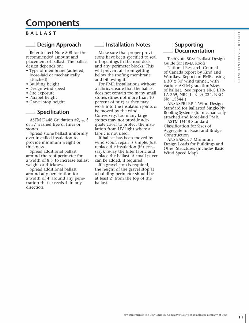
®™Trademark of The Dow Chemical Company (“Dow”) or an affiliated company of Dow
COMPONENTS
–Ballast
1 1
ComponentsB A L L A S T
Design ApproachRefer to TechNote 508 for the
recommended amount andplacement of ballast. The ballastdesign depends on:• Type of membrane (adhered,loose-laid or mechanicallyattached)
• Building height• Design wind speed• Site exposure• Parapet height• Gravel stop height
SpecificationASTM D448 Gradation #2, 4, 5
or 57 washed free of fines orstones.Spread stone ballast uniformly
over installed insulation toprovide minimum weight orthickness.Spread additional ballast
around the roof perimeter fora width of 8.5' to increase ballastweight or thickness.Spread additional ballast
around any penetration fora width of 4' around any pene-tration that exceeds 4' in anydirection.
Installation NotesMake sure that proper provi-
sions have been specified to sealoff openings in the roof deckand any perimeter blocks. Thiswill prevent air from gettingbelow the roofing membraneand billowing it.For PMR installations without
a fabric, ensure that the ballastdoes not contain too many smallstones (fines not more than 10percent of mix) as they maywork into the insulation joints orbe moved by the wind.Conversely, too many largestones may not provide ade-quate cover to protect the insu-lation from UV light where afabric is not used.If ballast has been moved by
wind scour, repair is simple. Justreplace the insulation (if neces-sary), re-lay the filter fabric andreplace the ballast. A small pavercan be added, if required.If a gravel stop is required,
the height of the gravel stop ata building perimeter should beat least 2" from the top of theballast.
SupportingDocumentation
TechNote 508: “Ballast DesignGuide for IRMA Roofs”National Research Council
of Canada report by Kind andWardlaw. Report on PMRs usinga 30' x 30' wind tunnel, withvarious ASTM gradation/sizesof ballast. (See reports NRC LTR-LA 269, NRC LTR-LA 234, NRCNo. 15544.)ANSI/SPRI RP-4 Wind Design
Standard for Ballasted Single-PlyRoofing Systems (for mechanicallyattached and loose-laid PMR)ASTM D448 Standard
Classification for Sizes ofAggregate for Road and BridgeConstructionANSI/ASCE 7 Minimum
Design Loads for Buildings andOther Structures (includes BasicWind Speed Map)

®™Trademark of The Dow Chemical Company (“Dow”) or an affiliated company of Dow
COMPONENTS
–Pavers
1 2
ComponentsP A V E R S
DescriptionConcrete slab pavers or inter-
locking pavers can be used tosupplement or replace conven-tional stone ballast requirementsand create a surface for rooftopdecks, walkways, terraces, gardensand similar applications.
Note: For structural plaza deckdesign, such as for parking decksand other high-traffic areas, thedesign is the responsibility of anarchitect and/or structural engineer.
FunctionNote: For additional information,see “Ballast” on page 10.
Narrow roof walkways foraccess: Pavers can be placed tofacilitate access to rooftopequipment.Prevent wind scouring: In
exposed areas or areas of highwinds, pavers may be required.In certain conditions, the paversshould be strapped togetherusing galvanized or stainlesssteel straps, mechanically fas-tened to each paver.Perimeter ballast: Additional
ballast is required around thebuilding perimeter in a PMRdesign. Depending on thedesign, pavers can be installedinstead of conventional stoneballast.Plaza-deck design: For light
traffic requirements, the stoneballast can be replaced withconcrete pavers completely. Inmany cases, the pavers must beraised from the surface of thefabric and insulation. See“Installation Notes” for details.
SpecificationPAVERSConcrete pavers shall be man-
ufactured from minimum 3,000lb/in2 concrete with a minimumweight of 18 lb/ft2.When ribbed insulation is not
used and the total area to becovered by pavers is more than10 percent and the location hasmore than 3,000 heating degree-days, pavers should be raisedfrom the surface of the fabricand insulation using spacersto maintain at least a 3/16"ventilating air space (“diffusionopen” design). The spacer can be:• 1" thick insulation cut into6" square blocks and placedunder the four corners of thepaver (limited to 108 lb/in2
live loading)• Preformed pavers with at leasta 3/16" foot in each corner orribbed undersurface
• Paver pedestal of injectionmolded, weathering-grade plastic,installed under each corner(e.g., PAVE-EL by Envirospec Inc.,Terra-Tabs by Wausau Tile, etc.)
• Layer of pea gravel 1" (min.)free of fines
Note: This air space is not requiredif the pavers are covering only alimited area (less than 10 percentof roof area), such as corners ornarrow roof walkways.
PAVER STRAPPING ANDFASTENERS (IF REQUIRED):Straps shall be of 22 gauge
galvanized or stainless steel,3" wide and 12' long.Fasteners shall be 1/4" x 1-1/4"
corrosion-resistant metalanchors, expanded in pre-drilledholes (e.g., Zamac Nailin #2814by Powers Fasteners, Inc).
Installation NotesWhen pavers cover more than
10 percent of the insulation sur-face and are located in climateswith more than 3,000 heatingdegree-days, create a 3/16" spacebetween the insulation andthe underside of the pavers.In colder climates, the air spacewill minimize any freeze-thawspalling on the concrete andmoisture build-up in the insula-tion due to vapor drive from theinside.

®™Trademark of The Dow Chemical Company (“Dow”) or an affiliated company of Dow
COMPONENTS
–All
OtherComponents
1 3
ComponentsA L L O T H E R C O M P O N E N T S
DescriptionMEMBRANESThe membrane is the flexible
or semi-flexible waterproofinglayer on the roof deck. In a PMRapplication, the membrane issandwiched between the roofdeck and the insulation.Membranes fall into three
general categories: built-up roof(BUR), two-ply modified bitumen,single-ply (sheet) or liquidmembranes.
Note: PMR assemblies should beinstalled with adhered membranesonly.
BUR membranes are semi-flex-ible, multi-ply roof membranes,consisting of plies or layers ofsaturated felts, coated felts, fab-rics or mats between alternatelayers of bitumen, either asphaltor coal tar based.
Modified bitumen membranesare similar to BUR membranes,but instead are manufactured ina production facility, usingasphalt modified with variousadditives. The membrane is fullyadhered and the seams overlapto provide an uninterruptedwaterproof layer.
Sheet or single-ply membranesare prefabricated sheets of polymer-based material, such as thermo-plastic (e.g., PVC), elastomeric(e.g., EPDM) or modified bitumenwith polymer modifiers. Single-ply roofs can be:• Fully or partially adhered: Themembrane is fully or partiallyadhered to the underlying sub-strate with a flood coat.
• Loose-laid: The membrane isnot attached to the substrateexcept at the perimeter and atpenetrations. In a PMR assem-bly, the loose-laid membraneis held in place with full ballast.(See “Ballast” on page 10 fordetails.) Care must be taken toensure that air infiltrationunderneath the membrane isprevented.
• Mechanically fastened: Themembrane is attached atdefined intervals to the sub-strate. Mechanical fasteningmay use various fasteners and/or other mechanical devices,such as plates or battens.
• Self-adhering: The membrane isadhered to a substrate and toitself at overlaps without theuse of an additional adhesive.This is usually accomplishedwith a surface adhesive pro-tected by a release paper orfilm that prevents the mem-brane from bonding to itselfduring shipping and handling.
Note: With some membranes,manufacturers may recommend aslip sheet (e.g., 4-mil polyethylenefilm) over the membrane to preventadhesion of the foam to themembrane or plasticizer migration(e.g., chemical attack) to theSTYROFOAM™ extruded poly-styrene insulation. Consult themembrane manufacturer forrecommendations.
Liquid membranes are appliedin-situ as a liquid that hardens orsets into a continuous, monolithicmembrane over the substrate.These liquids are generallyapplied by spraying or withrollers and include:• Hot-applied rubberizedasphalts, a blend of asphalt,mineral fillers, elastomers, virginor reclaimed oil. Some versionsconsist of two coats of rubber-ized asphalt with a polyestermat in between (fully reinforcedor two-ply system).
• Cold-applied liquid com-pounds consist of emulsionsand solutions of resins, elas-tomers (e.g., polyurethanes,silicones, acrylics, etc.) andbitumens and/or modifiedbitumens.
FLASHINGSFlashings are materials used
to weatherproof or seal the roofsystem edges at perimeters,penetrations, walls, expansionjoints, valleys, drains and otherplaces where the roof coveringis interrupted or terminated. Forexample, membrane base flash-ing covers the edge of the fieldmembrane, and cap flashingsor counterflashings shield theupper edges of the base flashing.
ROOF DECKThe roof deck (including
drains and gutters) is the struc-tural component of a building’sroof. The deck must be capableof safely supporting the designdead and live loads, includingthe weight of the roof systemsand the additional live loadsrequired by governing buildingcodes.Decks are either non-com-
bustible (e.g., corrugated metal,concrete or gypsum) or com-bustible (e.g., wood plank orplywood), and provide the sub-strate to which the roofing orwaterproofing system is applied.

®™Trademark of The Dow Chemical Company (“Dow”) or an affiliated company of Dow
COMPONENTS
–All
OtherComponents
1 4
FunctionThe roof deck should:• Provide structural support toaccommodate both live anddead loads without significantdeflection.
• Provide dimensional stability byforming a stable substrate notaffected adversely by cyclicalthermal- and moisture-inducedmovement.
• Provide fire resistance as deter-mined by the building typeand intended use.
• Provide a substrate for the roofsystem.
• Accommodate building move-ment. Where necessary, buildingexpansion joints and roof areadividers should be designedand installed.
• Provide for drainage (either bysloping the roof deck or usingtapered insulation or both).The roof surface should besound and should drain waterfreely within 48 hours follow-ing a rain. Every effort shouldbe made to isolate and correctthe causes of any standingwater or ponding on the roof.CRCA and NRCA recommenda minimum slope of 1/4" perfoot (2 percent). TheInternational Building Code(IBC) also requires a slope of1/4", except for coal tar mem-branes that require 1/8" slope.However, if the roof isdesigned to allow ponding,ensure the insulation is notadhered to the membraneand a filter fabric is used.
• Provide suitable roof drainsand gutters. Care should betaken to prevent ballast fromentering the drains and/orgutters by using perforatedcollars or paving stones.When concerns exist, adrainage assessment shouldbe conducted per SMACNAguidelines.
The membrane should:• Provide a continuous water-proofing barrier to protect theinterior environment.
• If the membrane is tacky, usea slip or separation sheet (e.g.,4-mil polyethylene) to mini-mize adhesion between themembrane and insulation.
• If there are compatibility issueswith the membrane, such aswith certain PVC or coal tarmembranes, refer to themanufacturer’s or supplier’srecommendations. In somecases, a slip or separation sheet(e.g., 4-mil polyethylene) maybe required.
The flashing should:• Provide a continuous water-proofing barrier when tiedinto the membrane to protectthe interior environment.
• Extend well above the expectedhigh water level (typically 8"minimum).
SpecificationGeneral: The overall system(including membrane and insu-lation) should be designed so thatthe dew point is located abovethe membrane. The system shouldbe designed so that freezing willnot occur at the membrane level.Where required, an adequate
thermal barrier should be pro-vided between the insulation andthe interior of the building. Thethermal barrier may consist of thedeck, a ceiling assembly or anunderlayment board equivalentto 1/2" gypsum board.
Membrane: Refer to membranemanufacturer’s literature fordetails. The manufacturer orsupplier of the membrane shallbe responsible for determiningcompatibility of the membranewith STYROFOAM™ extrudedpolystyrene insulation.
Roof deck and flashing: Referto general roofing specificationfor details.
Installation NotesSee the NRCA Roofing and
Waterproofing Manual – FifthEdition. Online edition availableat: http://www.nrca.net/rp/technical/manual/manual.aspxSee the CRCA Roofing
Specification Manual. Detailsavailable at: http://www.roofingcanada.com/ItemsForSale.asp
ComponentsA L L O T H E R C O M P O N E N T S

®™Trademark of The Dow Chemical Company (“Dow”) or an affiliated company of Dow
CONDIT
IONS,IS
SUES
AND
RATIN
GS
–Specia
lConditio
nsand
Issues
1 5
Conditions, Issues and RatingsS P E C I A L C O N D I T I O N S A N D I S S U E S
Cold RainPhenomenon
THE ISSUE“Cold rain phenomenon” (or
“cold water wash”) occurs dur-ing periods of cold rain and/ormelting snow or when the ambi-ent condition is 33°F to 50°F.In these conditions, the decktemperature may be temporarilyreduced. The issue is that theremay be additional heat loss, andin buildings with high humidity,such as pulp and paper mills,the likelihood of condensationincreases.
DISCUSSIONIncreased heat loss: Heat loss
studies have shown that extraheat loss in PMR systems duringperiods of “cold rain” is a tem-porary phenomenon, occurringonly during the short time ofcold rain in a heating season. Infact, cold rain in the coolingseason creates a cooling advan-tage for a PMR system. Studiescomparing a conventional versusPMR assembly show only a 3percent overall heat loss disad-vantage for the PMR assembly.
High temperature/high humiditybuildings: According to NRCA, abuilding with 45 percent RH isconsidered high moisture occu-pancy. Other buildings, such aspulp and paper mills, textilemills and natatoriums, can havean even higher internal humidity.Combining high humidity witha higher than normal operatingtemperature results in a “hightemperature/high humidity”building environment thatrequires special designconsideration.
The severe operating conditionsof high temperature/high humiditybuildings are particularly prob-lematic for conventional roofsystems. The high temperaturesdrive the high humidity upinto the roof system, resultingin severe condensation andpremature deterioration of theinsulation and roof deck.A PMR system offers an inher-
ent design solution for thismoisture problem. The water-proof roof membrane is anexcellent vapor retarder. Withthe membrane directly on theroof deck and the insulationabove the membrane, the mem-brane effectively blocks watervapor from reaching the insula-tion. Also, the membrane ismaintained at a temperaturenear that of the interior, dramat-ically reducing the probability ofcondensation on the membraneand minimizing the possibilityof premature roof failure.The “cold rain phenomenon”
can change this situation. Coldrain, filtering past the insulationto the membrane, can cool themembrane and the deck below,resulting in a temporary con-densation condition on theunderside of the deck. For somebusinesses, like pulp and papermills, this dripping condensationcan create problems with themanufacturing processes andproducts, causing decreasedproductivity and increasedproduction costs.To solve this problem, a thin
layer of insulation can be placedbelow the membrane. This layerkeeps the roof deck warm duringbrief cold rain periods – main-taining the inherent advantagesof a PMR system while mitigat-ing the problem of the “coldrain phenomenon.”See TechNote 507: “STYROFOAM™
Insulation in the OptimumDesign System for Pulp & PaperMill Roofs” for additional details.
CONCLUSIONThe effect of “cold rain phe-
nomenon” is temporary anddoes not have a significant over-all effect on the performance ofa PMR assembly. Generally,thicker amounts of insulationare not required to counteractthe negative effects of cold rain.In high humidity and high
temperature applications, sand-wiching the membrane betweentwo layers of insulation, coupledwith a vapor retarder on theroof deck will address condensa-tion problems in high humidityroofing systems. Remember thatthe thicker insulation layershould be above the membraneto ensure the dew point is abovethe membrane.

®™Trademark of The Dow Chemical Company (“Dow”) or an affiliated company of Dow
CONDIT
IONS,IS
SUES
AND
RATIN
GS
–Specia
lConditio
nsand
Issues
1 6
MoistureAbsorption
THE ISSUESTYROFOAM™ extruded poly-
styrene insulation will absorbwater and the insulation valuewill be reduced.
DISCUSSIONIn a PMR design, it is critical
that any insulation installedabove the membrane can per-form in a wet environmentwithout any detrimental effectson its long-term performance.STYROFOAM™ extruded poly-styrene insulation has a uniqueclosed-cell structure that providesexcellent moisture resistanceand long-term R-value.Nine PMR systems were moni-
tored over a period of 22 yearsand the insulation propertiesassessed. The average moisturecontent of the insulation was0.9 percent on a percent byvolume basis, with a retainedR-value of 96 percent.In plaza deck designs, it is
important that a drainage layerbe created above the insulation,allowing precipitation to drainoff the top surface of the insula-tion, creating a “diffusion open”assembly. If the insulation issandwiched between a vaporbarrier (e.g., pavers) and the roofdeck, vapor cannot escape so itis driven back into the insula-tion. To create a “diffusionopen” layer, ensure imperme-able roof coverings (such aspavers) have a ventilating airspace. This could be a layer offine-free gravel or a 3/16" mini-mum air space. See “Pavers” onpage 12 for additional details. Inaddition, if the wearing surfaceis installed in direct contactwith the insulation, moisturemay become trapped and freeze-thaw cycling could causespalling on the bottom of thewearing surface.
Always ensure that the roofdeck has proper drainage; if thePMR system has significantponding (e.g., standing water), theinsulation will not be “diffusionopen.” Follow roofing associationguidelines for drainage recom-mendations.
CONCLUSIONSTYROFOAM™ extruded
polystyrene insulation offersdemonstrated long-term perform-ance in a PMR assembly.
DimensionalStability
THE ISSUESTYROFOAM™ extruded poly-
styrene insulation “shrinks”over time, leading to increasedheat loss.
DISCUSSIONAll building materials will
experience dimensional changedue to temperature fluctuations.STYROFOAM™ extruded poly-styrene insulation is no different.For example, the coefficient of
expansion of STYROFOAMextruded polystyrene insulationis 3.5 x 10⁻⁵ in/in/°F. A 2' x 8'sheet of insulation exposed to atemperature swing of 75°F couldresult in a maximum change ofjust 1/4" in the 8' direction.Once the temperature isreduced, the insulation willreturn to its original cut dimension.In addition, this theoreticalchange does not account for thetemperature profile across theinsulation. For example, whileone side may see a large temper-ature swing, the underside maysee only a small change.This relatively small gap
between the boards does not sig-nificantly increase the heat lossthrough the board joints. Inheat loss studies comparing PMRversus conventional roofs, therewas no significant differencebetween the two systems. Thefindings showed that the PMR
system used 3 percent moreenergy per year.In addition to addressing the
coefficient of expansion, anotherconsideration is the “creep” ofmaterials. Creep is the permanentdeformation resulting fromcontinuous, long-term dead(or non-moving) loads. Creepis generally only an issue forSTYROFOAM insulation used inpavements, airport runways,parking decks, floors, etc. –installations where the insulationis used to carry a significantload for a long time. In theseapplications, higher compressivestrength insulation may berequired.
CONCLUSIONAll building materials have a
coefficient of expansion thatresults in dimensional changewith temperature fluctuations.The dimensional change thatoccurs in STYROFOAM™ insula-tion in a PMR assembly does notsignificantly impact the system’sthermal performance.
Conditions, Issues and RatingsS P E C I A L C O N D I T I O N S A N D I S S U E S

®™Trademark of The Dow Chemical Company (“Dow”) or an affiliated company of Dow
CONDIT
IONS,IS
SUES
AND
RATIN
GS
–Specia
lConditio
nsand
Issues
1 7
Green Roof DesignTHE ISSUECan PMR assemblies be used
for “green roof” designs?
DISCUSSIONIn a “green roof” design, the
ballast in a PMR assembly isessentially replaced with greenmaterial – usually soil andplantings – plus a drainage layerdirectly on top of the insulation(Figure 6). Replacing conven-tional ballast with vegetation canlimit storm water runoff and, byfiltering the runoff through theplants, also improve the qualityof the runoff. The plantings notonly ballast the insulation, theycan, depending on the configu-ration, also add additionalR-value to the roof assembly.Green roofs provide habitat forinsects and other wildlife andoften are considered in buildingsapplying for LEED†† (Leadershipin Energy & EnvironmentalDesign) certification.Many materials may be suitable
as ballast, provided they arecompatible with the insulation,prevent flotation, shield ultra-violet light and provide a ClassA fire-resistant roof finish.The roof structure must also be
designed to accommodate thedead load from the additionalweight of the plantings (includingwhen they are fully saturated byrainfall and covered in severalfeet of snow), plus any live loadfrom traffic, if applicable. It isalso important to design theroof slope and drainage systemto accommodate rain runoff.
Figure 6: Green Roof Design
PMR assemblies are ideal forgreen roof designs:• The membrane is protectedunder the insulation.
• Because STYROFOAM™ extrud-ed polystyrene products comein a range of compressivestrengths, the insulation layercan be designed to withstandthe higher dead loads.
• STYROFOAM insulation isproven to outperform in amoist environment.
• STYROFOAM insulation has ahigh modulus of elasticity,allowing it to perform underlong-term live or cycle loading.Maximum recommendeddynamic (live) load is 1/10 ofthe rated compressive strengthfor 1,000,000 repetitions toaddress creep and fatigueguidelines.
Typically, a drainage layer isplaced over the insulation todirect runoff to the drains, aswell as keep the top surface ofthe insulation “diffusion open.”(See “Moisture Absorption” onpage 16 for details.) Thisdrainage layer usually includes afabric over the insulation to pro-tect the joints and keep themopen for drainage. Any stoneused for this drainage layer mustbe clean and have a low per-centage of fines. In some cases,a drainage mat combined with afilter fabric has also been usedsuccessfully to create the neces-sary air space.
For additional information ongreen roof design, see:
Design Guidelines for Green Roofs,by Steven Peck and MonicaKuhn, B.E.S., B. Arch., OAA, anOAA and CMHC publication,available at http://www.cmhc-schl.gc.ca
CONCLUSIONPMR assemblies are ideally
suited to green roof designs.
Vegetation
Soil
System Filters
Filter Fabric
STYROFOAM™ExtrudedPolystyreneInsulation
Membrane
Deck
††Trademark of the U.S. Green Building Council
Conditions, Issues and RatingsS P E C I A L C O N D I T I O N S A N D I S S U E S

®™Trademark of The Dow Chemical Company (“Dow”) or an affiliated company of Dow
CONDIT
IONS,IS
SUES
AND
RATIN
GS
–Specia
lConditio
nsand
Issues
1 8
Finding Leaksin a PMR
THE ISSUEIs it more difficult to locate a
leak with a PMR or conventionalroof assembly?
DISCUSSIONBuilding upon years of in-field
experience, the majority of roofleaks in PMR systems occur atflashing as opposed to the inte-rior field area. The field area isprotected from physical abuse,UV attack and thermal cycling –all factors that are the primarycauses of roof failures – by boththe insulation and ballast overthe membrane. However, some-times interior field leaks dooccur.Concrete decks: For PMR
installations on concrete decks,generally the membrane is fullyadhered to the deck. This simpli-fies leak detection because theleak is localized. For example,the leak in the interior will beexactly where the hole in themembrane is located. If themembrane is not adhered, thewater can run under the mem-brane for many feet beforeentering the building – just likein a conventional roof.Steel decks: For PMR installa-
tions on steel decks, a layer ofinsulation or other substrate(e.g., drywall) is placed first toprovide a base for the mem-brane – exactly the same as in aconventional roof. The sametype of leak detection effort isrequired for both PMR and con-ventional roofs on steel decks.Wood decks: On wood decks
with a PMR installation, themembrane is typically a feltlayer and two or three pliesmopped on top. In a conven-tional installation, the insulationis fastened to the deck and thenthe membrane is applied. Bothof these approaches will allowthe water to run to the deckjoints prior to entering thebuilding.
CONCLUSIONNot only do PMR assemblies
have fewer leaks in the firstplace, PMR assemblies overconcrete decks with bondedmembranes have definite advan-tages when isolating any leaksthat do occur. Both conventionaland PMR roofs over steel orwood decks require the sameleak detection strategies. Inaddition, because PMR roofs areeasier to repair and typically allof the original materials can bereused (ballast and insulation),this environmentally friendlyfeature can save money.
Low TemperatureApplications
THE ISSUEPMR assemblies should
not be used in low temperatureapplications because of thepotential adverse effect on theSTYROFOAM™ extruded poly-styrene insulation.
DISCUSSIONIn a low temperature applica-
tion (e.g., freezers), the interiorspace has a low temperature andlow water vapor pressure(humidity). In contrast, thewarm outside temperature andhigher water vapor pressurecauses a vapor drive toward theinterior space. Unless addressed,this vapor can condense in theinsulation and lower the R-valueof the system. It can also con-dense on the membrane andfreeze, gradually forming a layerof thick ice.Typically in low temperature
applications, the membrane isplaced on the “warm side” – orthe exterior in a conventionalroofing application.
CONCLUSIONIn low temperature applications
(e.g., freezers), a conventionalroof may offer performancebenefits.
High TemperatureInstallation
THE ISSUEIn high temperature locations,
PMR assemblies should notbe covered with a dark fabricprior to laying the ballastbecause of the potential adverseeffect on the STYROFOAM™
extruded polystyrene insulation.
DISCUSSIONLike many insulations, higher
temperatures may cause permanentdistortion and/or long-termcreep. The maximum usetemperature for STYROFOAM™
extruded polystyrene insulationis 165°F for continuous use,with short-term exposure up to190°F.Typically, this concern arises
in warmer locations (e.g., south-ern U.S.) when STYROFOAMinsulation is placed underneatha dark fabric prior to laying theballast. Given the right condi-tions, the temperature on thetop of the insulation may reachclose to the upper limits forpolystyrene insulation and causesome distortion. Experience hasshown that when the STYROFOAMinsulation is exposed to bothdirect sunlight and an outdoorair temperature over 90°F, distor-tion of the foam can occur in aslittle as 30 minutes when aheavy fabric is over the insulation.To prevent this phenomenonduring hot weather, temporarilyplace white opaque polyethylenefilm on the fabric until theballast is laid.
CONCLUSIONIn high temperature locations,
the temporary use of whiteopaque polyethylene film laidon the fabric until the ballast islaid will prevent any distortionof the insulation.
Conditions, Issues and RatingsS P E C I A L C O N D I T I O N S A N D I S S U E S

®™Trademark of The Dow Chemical Company (“Dow”) or an affiliated company of Dow
CONDIT
IONS,IS
SUES
AND
RATIN
GS
–Specia
lConditio
nsand
Issues
1 9
Membrane SeamFailure
THE ISSUEFailures at the seams in
thermoset membranes maybe worse with PMR becausethe membrane stays damp.
DISCUSSIONThermoset membranes (such
as EPDM and neoprene) werehistorically seamed with a con-tact adhesive. Seam failure dueto moisture intrusion or othercontaminant was a concern forthis type of membrane becausethe membrane stays damp in aPMR, potentially resulting in anincrease in seam failure. In fact,Dow never received a complaintabout this perceived concern.In today’s EPDM system, a
seam tape is used. This tape hasexhibited excellent performanceand this is no longer an issue.
CONCLUSIONThere are no documented
cases of seam failure related tothe PMR application.
Plant Growth onPMR Assemblies
THE ISSUEPeriodically, plant growth
will occur on PMR and otherlow-sloped roofs. Can this beavoided?
DISCUSSIONAt times, grass, weeds or small
trees may grow on both PMRand conventional roofs. Goodroofing practice should includea maintenance program thatincludes periodic inspection forthis type of growth. Any plantgrowth should be pulled outand, if required, the area treatedwith a weed killer.Roots from plant growth can
sometimes damage the mem-brane if left unchecked. With aPMR system, there is less chanceof this happening since themembrane is protected by theinsulation, fabric and ballast.
CONCLUSIONA preventive maintenance and
inspection program shouldinclude inspection and removalof any plant growth.
Conditions, Issues and RatingsS P E C I A L C O N D I T I O N S A N D I S S U E S

CONDIT
IONS,IS
SUES
AND
RATIN
GS
–Fire
and
Win
dRatin
gs
2 0
OverviewFire and wind ratings are
required to meet building coderequirements. Typically, a PMRassembly, including roof deck,membrane, insulation andballast, is tested in exactly thesame configuration as wouldbe constructed in the field. Nodeviation from the componentspecification is allowed.Underwriters Laboratories Inc.
(ULI), Underwriters LaboratoriesCanada (ULC) and FactoryMutual (FM) have developed testmethods to rate the fire andwind properties of assemblies.
For the most current listings,contact Dow at 1-866-583-BLUE(2583).
Test MethodsFIRE RESISTANCE RATINGS –FIRE WITHIN A BUILDINGBoth ULI and ULC test roof
assemblies based on the type offire exposure. For fires originatingwithin a building, roof assembliesare assessed using either ANSI/UL263 or CAN/ULC S101-M.When testing for fires originat-
ing within a building, a full-scaleroof system is exposed to acontrolled fire in order to assessa construction/assembly thatcan contain a fully developedfire. The Fire Resistance Ratingrepresents the time it takes forthe temperature on the unex-posed side of the assembly toincrease by 250°F.
A sample measuring approxi-mately 14' x 17' is used,including the decking material,any suspended ceiling, hangers,insulation, etc. The sample isthen exposed to a fire withtemperatures reaching 1,000°Fat five minutes and then 1,700°Ffor a specified time. During thetest, a load is applied to the floorto represent the maximum loadthe joists are designed to support.
EXTERNAL FIREPERFORMANCE OFA ROOF ASSEMBLYThe fire resistance performance
of roof coverings exposed tosimulated fire source originatingoutside a building is conductedin accordance with UL 790(ASTM E108) or CAN/ULC S107-M.Three classifications are available.
Class A roof covering:• Effective against severe fire testexposures
• Provides a high degree of fireprotection
• Not expected to produce flyingembers
• Does not slip from positionduring the test
Class B roof covering:• Effective against moderate firetest exposures
• Provides a moderate degree offire protection
• Not expected to produce flyingembers
• Does not slip from positionduring the test
Class C roof covering:• Effective against light fire testexposures
• Provides a light degree of fireprotection
• Not expected to produce flyingembers
• Does not slip from positionduring the test
Note: PMR assemblies ballastedwith a minimum of 9 lb/ft2 ofstone ballast (or pavers installedwith a maximum gap of 1/4")achieve a Class A rating.
FM TESTS FORWIND PERFORMANCEFactory Mutual approved roof
assemblies are only required whenthe building is insured by FMGlobal. Building code authoritiesmay recognize some FMstandards; however, they do notrequire the use of FM approvedor accepted products and systems.FM 4450, “Approval Standard
for Class 1 Insulated Steel DeckRoofs,” and FM 4470, “ApprovalStandard for Class 1 RoofCovers,” are two recognizedlaboratory test methods fordetermining the wind-upliftresistances of roof assemblies.FM 4450 and FM 4470 are thebasis of FM’s 1-60, 1-90, 1-120,etc., approvals. For example, aClass 1-60 design resists a 60lb/ft2 uplift pressure for oneminute without loss of pressure.Dow has a PMR system rated
FM 1-90 that adheresSTYROFOAM™ extruded poly-styrene insulation to a BUR roofassembly with asphalt. This sys-tem can be used on both steeland concrete roof decks. Loose-laid single-ply roof membraneswith ballast are not listed in theFM approval guide since thereare not methods to test thesesystems for wind uplift. Loose-laid systems can be “accepted”by FM if the assembly is ballast-ed in accordance with FM LossPrevention Guide 1-29 andreviewed by the local FM engi-neering office.
IBC REQUIREMENTSFOR BALLASTED ROOFASSEMBLIESThe International Building
Code (IBC) requires that ballast-ed roofing assemblies, includingPMR assemblies, be ballasted inaccordance with ANSI/SPRI RP-4.This standard can be down-loaded (free of charge) atwww.spri.org
®™Trademark of The Dow Chemical Company (“Dow”) or an affiliated company of Dow
Conditions, Issues and RatingsF I R E A N D W I N D R A T I N G S

®™Trademark of The Dow Chemical Company (“Dow”) or an affiliated company of Dow
CONDIT
IONS,IS
SUES
AND
RATIN
GS
–Fire
and
Win
dRatin
gs
2 1
ULI Hourly FireResistance Ratings forPMR – Steel Deck
Note: Always refer to the actual listing for complete details, includingmaximum thickness of insulation allowed. For details, call Dow at1-866-583-BLUE (2583).
Assembly #
P-225, P-226, P-235(New PMR)
P-404(New PMR)
P-801, P-805(Retrofit PMR)
P-803(Retrofit PMR)
P-811(New PMR)
P-813(New PMR)
P-908
Rating (hrs)
1, 1-1/2
1-1/2
1, 1-1/2, 2
1, 1-1/2
1, 1-1/2, 2, 3
1, 1-1/2
2
Description
Steel deck1/2" or 5/8" Type X gypsum (varies)Bar joistsSuspended ceiling
Steel deck1" mineral or fiberboardBar joistsPlaster ceiling
Steel deckMineral or fiberboardsSpray fiber fireproofingBeam construction
Steel deckMineral or fiberboardsSpray fiber fireproofingBar joists
Steel deck5/8" Type X gypsumSpray fiber fireproofingBeam constructionSuspended ceiling (optional)
Steel deck5/8" Type X gypsumSpray fiber fireproofingBar joists
Steel deck3-5/6" vermiculite concreteBeam construction
Conditions, Issues and RatingsF I R E A N D W I N D R A T I N G S

®™Trademark of The Dow Chemical Company (“Dow”) or an affiliated company of Dow
CONDIT
IONS,IS
SUES
AND
RATIN
GS
–Fire
and
Win
dRatin
gs
2 2
ULI Hourly FireResistance Ratings forPMR – Concrete Deck
Assembly #
P-904, P-909,P-912, P-915(Retrofit PMR)
P-904, P-909,P-912, P-915(New PMR)
Rating (hrs)
2
2
Description
Precast concrete unitsMineral fiberboard
Precast concrete units1" gypsum board
ULI Hourly FireResistance Ratings forPMR – Other
Assembly #
P-229, P-505, P-507(New PMR)
Rating (hrs)
1, 1-1/2
Description
2' poured gypsum deckBar joistsSuspended ceiling
Conditions, Issues and RatingsF I R E A N D W I N D R A T I N G S

®™Trademark of The Dow Chemical Company (“Dow”) or an affiliated company of Dow
CONDIT
IONS,IS
SUES
AND
RATIN
GS
–Fire
and
Win
dRatin
gs
2 3
ULC Hourly FireResistance Ratings forPMR – Metal Deck
Assembly #
R-202, R-217(New PMR)
R-702, R-703(New PMR)
R-804(New PMR)
R-805, R-806(New PMR)
Rating (hrs)
1
1, 1-1/2
3/4, 1, 1-1/2,2, 3
1
Description
Steel deck1/2" gypsumBeams or bar joistsSuspended ceiling
Steel deck5/8" gypsumSpray cementitious mixtureBeams or bar joists
Steel deck5/8" Type X gypsumSpray fiber fireproofingBeam construction
Steel deck1/2" or 5/8" Type X gypsum (varies)Spray fiber fireproofingBeams or bar joists
Conditions, Issues and RatingsF I R E A N D W I N D R A T I N G S

Assembly #
P-229, P-505, P-507(New PMR)
®™Trademark of The Dow Chemical Company (“Dow”) or an affiliated company of Dow§StrataGuard is a trademark of Owens Corning§§DensDeck is a trademark of Georgia-Pacific
CONDIT
IONS,IS
SUES
AND
RATIN
GS
–Fire
and
Win
dRatin
gs
2 4
ULC Hourly FireResistance Ratings forPMR – Concrete Deck
Rating (hrs)
1, 1-1/2
Description
2' poured gypsum deckBar joistsSuspended ceiling
FM Hourly Fire ResistanceRatings for PMR
FM Class 1 Fire andWind Uplift
Note: Current FM wind tests cannot be used to evaluate loose-appliedroofing systems. FM Loss Prevention Guide 1-29 provides acceptedballasting requirements.
Assembly #
RC-227(New PMR)
RC-264(New PMR)
Rating (hrs)
1
1
Description
Steel deck1/2" Type X gypsumGypsum board ceiling
Steel deck1/2" Type X gypsumSuspended ceiling
Class
1-60, 1-90
Description
Steel deck1/2" StrataGuard§ or 5/8" DensDeck§§(mechanically fastened)3-ply BUR
Conditions, Issues and RatingsF I R E A N D W I N D R A T I N G S

NOTICE: No freedom from infringement of any patent owned by Dow or others is to be inferred. Because use conditions and applicable laws may differ from one location to another and may change with time, Customer is respon-sible for determining whether products and the information in this document are appropriate for Customer's use and for ensuring that Customer's workplace and disposal practices are in compliance with applicable laws and othergovernment enactments. The product shown in this literature may not be available for sale and/or available in all geographies where Dow is represented. The claims made may not have been approved for use in all countries. Dowassumes no obligation or liability for the information in this document. References to “Dow” or the “Company” mean the Dow legal entity selling the products to Customer unless otherwise expressly noted. NO WARRANTIES AREGIVEN; ALL IMPLIED WARRANTIES OF MERCHANTABILITY OR FITNESS FOR A PARTICULAR PURPOSE ARE EXPRESSLY EXCLUDED.
COMBUSTIBLE: Protect from high heat sources. Local building codes may require a protective or thermal barrier. For more information, consult MSDS or call Dow at 1-866-583-BLUE (2583). In an emergency, call 1-989-636-4400.
Building and/or construction practices unrelated to building materials could greatly affect moisture and the potential for mold formation. No material supplier including Dow can give assurance that mold will not develop in any specificsystem.
IN THE U.S.:• For Technical Information: 1-866-583-BLUE (2583)• For Sales Information: 1-800-232-2436
THE DOW CHEMICAL COMPANY• Building Solutions • 200 Larkin • Midland, MI 48674 • www.dowstyrofoam.com/architect
Form No. 179-05051-0713MCKMcKAY219202
Printed in U.S.A. ®™Trademark of The Dow Chemical Company(“Dow”) or an affiliated company of Dow

Craig A. Hargrove, AIA LEED AP directs Hoffmann Architects, Inc.’s New York City office. As Senior Vice President and Director, Architecture, he is responsible for the integrity, coordination, and oversight of diverse plaza and terrace rehabilitation projects. Stephanie L. Dillon, Assoc. AIA, Project Coordinator, has experience in all phases of plaza evaluation, waterproofing, design, and construction.
Craig A. Hargrove, AIA LEED AP and Stephanie L. Dillon, Assoc. AIA
Journal of architectural
technology published by
Hoffmann Architects, Inc.,
specialists in the rehabilitation
of building exteriors.
I S S U E 2 / 2 0 0 9 V O L U M E 2 6 N U M B E R 2
Fundamentals of Plaza Design
plaza can be an attractive ame-nity, especially in an urban area where open space is at a premium. But when age, deferred maintenance, de-sign defects, or faulty construction lead to unsightly weed growth and pooling water, dangerous tripping hazards and ice buildup, or costly maintenance de-mands, it might be prudent to protect that amenity by rehabilitating it.
The question is, “how?” (And, rea-sonably, “how much?”) The answer depends on the type of system that’s in place, the type you opt to install, the use of the plaza space, and the complexity and requirements of plant-ers, stairs, fountains, seating, and other features. To begin, a team of architects and/or engineers should evaluate the existing plaza or terrace and help es-tablish a realistic rehabilitation budget. Then, the design team should guide you in balancing project variables to achieve the desired look while meet-ing cost objectives.
A well-designed plaza or terrace not only reduces upkeep costs, it also attracts tenants, increases property value, and enhances outdoor space. With reductions in energy and main-tenance expenses afforded by “green” design principles and sophisticated water movement strategies, plaza
or terrace rehabilitation can provide excellent return on investment.
Plaza Use and Configuration
When considering options for plaza or terrace design, an architect or engineer will first assess the function and composition of the space. A plaza over which vehicles routinely drive demands a different type of assembly than does a roof terrace that sees only maintenance foot traffic.
Similarly, a private terrace for the exclusive use of building tenants has different design considerations than does a plaza classified as “privately owned public space” or one in a busy campus setting. Access, circulation, furniture, decorative elements, and plantings must be coordinated to facilitate intended usage. Paving assemblies and materials, as well as any waterproofing systems, are thus dictated not only by the form of the plaza or terrace space, but also by its function. Historic planning regulations may place further restrictions on surfacing options.
Types of Paving Assemblies
The surfacing system needs to ac-commodate the volume and type of anticipated traffic, while meeting
Plaza investigation by an experienced architect or engineer uncovers the causes of water damage or deterioration.
A

2
J O U R N A L
Waterproofing is the central concern for a terrace or plaza that is also a roof.
The membrane. Once the waterproofing has been installed on a plaza or terrace, it is buried beneath tons of overburden, making it virtually impossible to access should problems arise. In all horizontal waterproofing applications, choosing and correctly applying the membrane is critical, but plazas and terraces demand a more conservative approach than do roofs or parking structures. Generally speaking, the options are:
Choice of membrane is situation-specific, and demands holistic consideration of the entire plaza. Only by analyzing all variables, from weather to traffic to load limits to space constraints, can a design professional determine the appropriate assembly.
The substrate. The deck should be cleaned of debris and properly pre-pared to facilitate adhesion. A fully adhered system prevents moisture that does penetrate the membrane from travelling underneath it. Spot repairs can then be completed without tearing up the entire plaza in search of the water entry point.
The protection. Drainage mats atop the membrane system direct water to drains, and protection boards can provide additional coverage in high-wear-ing areas. Insulation helps control energy costs.
The paving. Structural analysis must confirm that the building can accommo-date the chosen paving system, as well as additional loading from snow, ice, wind, pedestrians, and plantings.
The result. Waterproofing concerns shouldn’t undermine a plaza’s allure. A well-designed, properly installed plaza or terrace creates usable outdoor space above a built structure, a valuable asset in a dense urban setting.
Comparison of Waterproofing Systems for Plazas and Terraces
Membrane system Installation Puncture
resistanceCrack bridging Strong suit Weak spot
Single-plySheets adhered to deck, with glued, taped, or welded seams.
Poor FairCold, low-odor application.
Seam quality de-pends on skilled installation. No redundancy.
Multi-layer and combination
Multiple sheets bonded in layers by flame or by cold adhesive.
Excellent ModerateRedundancy, via layered materials.
Height restric-tions may preclude use in some retrofit applications.
Fluid-appliedLiquid binder applied to deck, with embedded reinforcing.
Good Poor
Seamless, with smooth transition from horizontal to vertical.
Poor adhesion or uneven coverage if prepared or applied incorrectly.
Plazas Over Occupied Space
design goals for drainage, loading, sit-ing, and usage. What are the benefits, drawbacks, and appropriate applica-tions for each type of system? Here are the basics:
Light DutyIf the plaza or terrace is designed to function as an extension of the building interior, with space for dining, seating, or entertaining, then the finish surface will need to be nearly level, while still allowing for the effective removal of water. For light pedestrian traffic, there are two basic options: a paver-on-pedestal or sand-set system.
Features. Paver-on-pedestal: Wa-terproofing membrane adheres to substrate, which slopes to drains. Columnar pedestals are individually set, at graduated heights, atop the insulation or a protection board, to create a level support. Pavers are then supported by a pedestal at each corner. Open joints allow water to flow directly down to the sloped sur-face below and on to drains. Sand-set: Pavers are set atop compacted sand, with small butt joints (approx. 1/16 of an inch), into which additional sand is swept. Walking surface is pitched to bi-level drains.
Benefits. Quick and easy to install. Depending on material selection, light-weight systems can also be the
Installation of a paver-on-pedestal system. Pavers are supported only at corners, with fully open joints.

3
V O L U M E 2 6 N U M B E R 2
least expensive. Should any problems develop, the loose-laid pavers can be readily removed for maintenance, investigation, and repair.
Drawbacks. Open joints are notori-ously problematic for high-heeled shoes, and they can create tripping hazards should pavers become dis-placed. Snow removal must be done with a blower or shovel, as plows can dislodge pavers. Weight limitations may preclude not only snowplows but also, in the case of a plaza at the front entrance to a building, emergency ve-hicles. It is possible to accommodate occasional vehicular access with an open-joint system, but at a significantly greater construction cost.
Medium DutyFrequent and heavy foot traffic, such as on a college campus or in a shop-ping mall, demands a more resilient system. An asphalt-set system with sand-swept joints can provide a landscaped pedestrian setting while holding up to the abuses of shoes and occasional light vehicles, like golf carts.
Features. Modular brick, stone, or concrete pavers are set on an asphalt/
sand composite bed, atop asphalt or cast-in-place concrete slabs separated by expansion joints. Drainage takes place predominantly at the surface level, although bi-level drains should be used to remove any water that does penetrate below the pavers.
Benefits. The asphalt-set paver system can accommodate much greater loads without cracking or displacement than can a paver-on-pedestal system, be-cause the load is supported across the entirety of each paver, rather than only at corners. Although the setting bed is still 90% sand, the addition of asphalt creates a more durable paving assembly than the simple sand-set system. Ap-plication of a neoprene tack coat adds further resilience.
Drawbacks. As the frequency and weight of traffic increases, so do costs. Medium duty plazas are more expen-sive to install than are light duty plazas, and the level of traffic demands more vigilant maintenance. Because asphalt-set pavers are more secure than are their light-duty counterparts, removal and replacement present challenges, as does accessing underlying waterproof-ing membranes.
Heavy DutyPlazas can also be designed to with-stand heavier vehicle traffic. The two options for durable support of cars and trucks are cast-in-place concrete or closed-joint paving systems.
Features. Where the plaza is set on grade, the subgrade must be well compacted. Insufficient compac-tion can result in cracking, heaving, and premature deterioration of the paving assembly. To withstand the rigors of vehicle traffic, hard joints, with mortar or sealant, are preferred. A cementitious setting bed adds durability.
Benefits. Aggressive resistance to traffic. Closed-joint systems can be designed to support 40 tons or more without damage.
Drawbacks. Material costs for high- traffic plazas are greater than for other plaza types. Maintenance, par-ticularly of joints, can be demanding, and replacement of pavers is difficult. Overly aggressive cleaning can blow out joints. Mortar or sealant lifespan should be considered as part of the cost equation, as joint material may need replacement every 7-10 years.
Representative Illustrations of Paving Assemblies
Heavy-Duty on gradeLight-Duty on gradeDrawings not to scale. Components can vary.
Medium-Duty over suspended slab
Finished Paving Surface
Setting Bed
Concrete or Asphalt Base
Processed Aggregate
Subbase
Undisturbed Soil
Finished Paving Surface
Neoprene Tack CoatSetting BedProtection Board
Insulation
Drainage Composit
WaterproofingSloped Concrete Fill
Structural Deck
Finished Paving Surface
Sand Setting BedFilter Fabric
Processed Aggregate
Undisturbed Soil

4
J O U R N A L
Code Compliance
When a plaza retrofit project is already underway is not the time to discover that building codes have changed, and that the seating for 20 must now be increased to 200, or that the plan needed to incorporate wheelchair access ramps. Local regu-lations stipulate when a plaza rehabili-tation is significant enough to demand updated code compliance. Plazas classified as “privately held public spaces” are generally subject to fairly rigid parameters governing occupancy, circulation, and hours of use, all of which will necessarily impact design.
Federal, state, and municipal regula-tions incorporate evolving “green” building codes, including provisions for plaza and terrace lighting, energy conservation, and water use. Security measures may also be dictated by lo-cal law. The design team can coordi-nate lighting, signage, access pathways, and landscape elements to maximize safety while meeting ecological build-ing standards.
Weight Limits
A plaza or terrace must support the weight of pavers, landscaping elements, seating, fountains, pedestrians, and, in some cases, vehicles. Grade-level terraces may also need to bear fire equipment, in an emergency. Ret-rofitting an existing plaza or terrace requires consideration of structural load-bearing capacity, especially when a new type of system is being installed that carries significant load beyond that of the existing assembly.
To avoid serious structural failure, the project architect or engineer should assess load-bearing capacity before plaza rehabilitation is undertaken.
THE REHABILITATION PROCESSColumbia University, College Walk
Construction of concrete retaining walls. The existing plaza.
Asphalt setting bed, ready to receive hexagonal asphalt pavers.
Installation of granite curbs.
The reconstructed pedestrian street. The redesigned paving system can withstand frequent, heavy pedestrian traffic, as well as vehicle use, while preserving the aesthetic character of the original plaza.

5
V O L U M E 2 6 N U M B E R 2
The Final Design
DrainageOnce owner’s expectations, usage, weight limitations, applicable building codes, and traffic exposure have been considered and a plaza system select-ed, it’s time to prepare the deck slope. Some original concrete decks were constructed dead level, leading to standing water and leaks. To correct the problem, slope fill may need to be added, which can create waterproof-ing challenges during construction, as well as raise load-bearing concerns. For areas that will contain tables and chairs, a 1/4 inch per foot slope is generally sufficient and maintains a suitable walking surface. However, a 1/4 to 1/2 inch per foot slope or more provides better drainage.
Drains should allow for water removal not only at the surface, but at the membrane or deck level, as well. Bi-level drains prevent trapped water from pooling atop the membrane, leading to premature deterioration. A combination of trench drains, which collect water from a larger area but are not designed for subsurface drain-age, and area drains, which are smaller but both efficient and bilevel, is often the best strategy for optimal drainage.
AppearanceMaterials. Plaza design must inte-grate the aesthetics of the outdoor space with those of the structure and surrounding area. Pavers of natural stone, brick, or concrete are the most common options, and care must be taken to balance appearance of these
materials with their durability. To avoid slippery surfaces, the coef-ficient of friction of various finishes must be considered, as well. Ice and snow removal approaches will also need to vary depending on the mate-rial selected, as some pavers respond better than others to deicing chemi-cals and snowplows.
Landscaping. Caretaking demands for landscaping can vary widely. Some plantings will demand daily mowing, weekly pruning, or monthly replace-ment, as well as costly irrigation systems, while many native or adaptive plants can get by with only natural rainfall and minimal attention. Eco-logically conscious landscaping design therefore saves not only on natural resources, but on costs.
Fields of Green
As green building initiatives are prompting federal, state, and local mandates on efficiency and sustainability, building codes and regulations change to reflect evolving ecological guidelines. Relevant requirements for efficient water use, storm water runoff management, light pollution reduction, and energy con-servation should be researched as part of the plaza or terrace design process. Some green ideas:
• Reuse pavers, where possible, after replacing a waterproof-ing membrane, both to reduce waste and save on material expenses.
• Use “dark sky” technology, which employs strategically positioned, low-radiance lighting, low-angle spotlights, and low-reflectance surfaces to cut down on light pollution. See sample plaza lighting diagram, above.
• Choose materials that reduce the “heat island effect.” Heat-trapping materials like asphalt, tar, and non-pigmented concrete raise air temperatures in cities. Besides plantings, which dissipate heat through evapotranspiration, certain building materials, like light-colored pavers, can help moderate temperature differences.
• Select native or adaptive plantings to conserve water and provide a habitat for bird and insect populations. Limit sod and turf grasses, which demand copious irrigation, mowing, and pest/weed control.
• Use efficient drip systems or subsurface sprinklers, in conjunction with reclaimed water, wherever irrigation is needed.
• Install “smart” controllers that vary light and water use by season, time of day, and weather.
• Employ mulching, alternate mowing, and composting, low-tech solutions that protect the environment and cut upkeep costs.
Above all, correct design and installation is the best way to build an environmentally sound plaza. When poor construction shortens a plaza’s lifespan, resources are wasted on rebuilding. The most ecological plaza is the one built to last.
Courtesy ERCO Lighting, Inc.

J O U R N A L
6
Maintaining Your Investment
You’ve invested in rehabilitating your plaza or terrace, and it looks great. How do you keep it up?
A little prevention goes a long way. By catching small problems before they become big ones, you can extend the lifespan of your plaza and avoid the undue expense of major repairs.
Daily. Sweep and remove trash and debris. Check for and treat ice and snow accumulation and clear tripping hazards.
Weekly. Wash down plaza. Clean joints and check drains and sump pumps. Trim and weed plantings and check for proper operation of irrigation systems. Do a safety check of railings, stairs, and lights.
Monthly. Replace dead plantings. Repair deteriorated mortar or sealant in joints.
Seasonally. Inspect sprinkler systems. Perform checks of the deck for de-terioration, leaks, cracks, or rust. Repair rust spots on railings, conduits, and other metal.
Annually. Fall: Drain irrigation and sprinkler systems for winter. Spring: Con-duct a structural inspection to plan for summer repairs.
Every 3-5 years. Replace sand in sand-swept butt joints.
If any leaks are reported, inspect and repair the waterproofing system as soon as possible to avoid further damage. Know your rights within the water-proofing warranty. If the problem persists, a design professional experienced in plaza remediation may need to conduct a more thorough investigation.
Additionally, planters require spe-cial waterproofing considerations, including root barriers and other extra protection over the membrane to avoid puncture. Structural load capacity may also be an issue when selecting plantings; beyond the weight of the plants themselves, growing media ranges in density and can add significant load.
Water features. Fountains and pools demand extra attention to water-proofing, especially over occupied space. Generally, a continuous waterproofing system is preferred, which can smoothly accommodate transitions from horizontal to vertical surfaces. Size and position of water features may also be dictated by traffic patterns, drainage sloping, and struc-tural capacity, as well as aesthetics.
Furniture. Seating can rest atop pav-ers, as with dining chairs and other temporary furniture, or it can be anchored to the plaza. Waterproofing and paving system options therefore may be dependent on the quantity and design of any furniture or orna-mental elements.
Lighting. Safety and appearance of a plaza or terrace at night depend on the quality and positioning of illumina-tion. A plaza which sees significant nighttime traffic will need thoughtfully designed lighting, including within foun-tains and around planters, to preserve the ambiance and protect pedestri-ans. More is not necessarily better : indiscriminate use of bright lights casts stark shadows and can actually dimin-ish visibility, and it also contributes to light pollution.
BudgetInitial installation and materials costs play a role in plaza design, but so do maintenance expenses. Be sure to understand up front what upkeep will be required for any systems under consideration. Some paving assem-
blies, such as sand-set systems, can be significantly cheaper to install, but demand vigilant maintenance to keep overgrown weeds from making the plaza look ragged and unkempt. For elevated plazas or terraces over occupied spaces, it can be tempting to cut costs by going with a less pricey waterproofing option, as the mem-brane lies below the surface, out of view. However, scrimping on water-proofing can cost more than it saves if the membrane fails prematurely, and the entire paving overburden must be ripped up to replace it.
AccessibilityLocal building codes, as well as the Americans with Disabilities Act (ADA), dictate the incorporation of ramps, el-evators, railings, and other accessibility provisions. Substantial rehabilitation
of a plaza provides an opportunity to upgrade entrance and egress path-ways to admit wheelchairs, strollers, or walkers, without compromising on aesthetics.
ScheduleAll rehabilitation projects for plazas over occupied space are, by necessity, on a tight schedule, as removal of the waterproofing system for any period of time opens the building up to water entry. Even plazas on grade may need to remain operational during con-struction, because of local government requirements, building access issues, or both. Organizing a plaza or terrace project into well-orchestrated phases can permit continuous usage while ac-complishing rehabilitation objectives.
The time of year at which a given waterproofing assembly can be
(continued on page 8)

7
Plaza and Terrace Rehabilitation
Hoffmann Architects focuses ex-clusively on the outsides of existing buildings. A substantial portion of our practice involves diagnosing and correcting problems within plazas, ter-races, roof setbacks, and courtyards.
For plazas and terraces over occupied space, Hoffmann Architects solves recurrent water infiltration by treating these areas as roofs that need extra protection, rather than as platforms for traffic on which waterproofing is merely an afterthought.
We create aesthetically appealing, technically appropriate plaza and ter-race solutions by locating the sources of deterioration and developing targeted programs of replacement or repair. Project oversight and guid-ance for ongoing maintenance see the rehabilitation through to a successful outcome, now and in the long term.
Among Hoffmann Architects’ plaza and terrace projects are:
College WalkColumbia UniversityNew York, New YorkPlaza Reconstruction
Phoenix Life Insurance CompanyOne American RowHartford, ConnecticutPlaza Investigation
The World BankWashington, District of ColumbiaTerrace Waterproofing System Design
Royal Bank of Scotland Greenwich Capital BuildingGreenwich, ConnecticutPlaza Rehabilitation
Purchase Campus CenterState University of New York (SUNY) Purchase, New YorkPlaza Reconstruction
Franklin & Marshall CollegeKeiper Hall/Green Room TheatreLancaster, PennsylvaniaPlaza and Stair Rehabilitation
The Ford FoundationNew York, New YorkPlaza Rehabilitation
The Schering-Plough CorporationKenilworth, New JerseyPlaza Investigation and Design
V O L U M E 2 6 N U M B E R 2
Paul Rudolph HallYale UniversityNew Haven, ConnecticutTerrace, Exterior Stair, Roof, and Skylight Rehabilitation and Reconstruction
Babbidge Library, White Building, and Bousfield HallUniversity of ConnecticutStorrs, ConnecticutInvestigation and Rehabilitation of Plazas and Exterior Stairs
Manhattan House O’Connor Capital PartnersNew York, New YorkRoof Garden and Terrace Rehabilitation
State of Connecticut Office Building25 Sigourney StreetHartford, ConnecticutPlaza Rehabilitation
The George Washington University’s Eye Street Pedestrian Mall in Washington, DC. Plaza Design and Rehabilitation

Unfortunately, many suffer from poor design, inappropriate materials selec-tion, faulty installation, or simply the effects of time and the elements. If your plaza or terrace evidences the following or other burdensome conditions, rehabilitation might prove cost-effective:
• Deterioration• Decreased usage• Rising maintenance expenses• Increased liability
Facing an ailing plaza can be daunting. But those who brave a plaza over-haul with forethought and care are rewarded with a functional, pleasant open space that demands little atten-tion or resources once it’s in place.
Hoffmann Architects, Inc.2321 Whitney AvenueHamden, CT 06518
ADDRESS SERVICE REQUESTED
JOURNAL is a publication of Hoffmann Architects, Inc., specialists in the rehabilitation of building exteriors. The firm’s work includes investigative and rehabilitative architecture and engineering services for the analysis and resolution of problems within roofs, facades, glazing, and structural systems of existing buildings, plazas, terraces and parking garages.
For address changes, free subscriptions, or information on the topics discussed in this issue, contact our Marketing Coordinator at 800-239-6665, [email protected], or :
2321 Whitney AvenueHamden, CT 06518203-239-6660
500 Fifth Avenue, Suite 830New York, NY 10110212-789-9915
2611 Jefferson Davis Highway, Suite 200Arlington, VA 22202703-253-9800
www.hoffarch.com
Editor : Alison HoffmannProduction: Cari Tate
Printed on 50% recycled paper.
J O U R N A L
installed may also affect a rehabilitation project’s scheduling. For example, ad-hesives and fluid-applied membranes must generally be applied when air temperatures are above approxi-mately 40°F and below 80°F, which may mean scheduling installation for late spring or early fall. Coordinating seasonal restrictions with building us-age demands and weather events can pose significant logistical challenges.
When to Rehabilitate: Cost-Benefit Analysis
Plazas and terraces are appealing features that attract tenants, raise property values, and provide aestheti-cally pleasing outdoor public spaces.
(continued from page 6)
This multi-level plaza over occupied space coordinates temporary and fixed furniture and planters with high- and low-traffic areas to achieve a practical, aesthetically appealing outdoor space.

Segmental Concrete Paving Units for Roof DecksIntroductionAn increasing amount of new and rehabilitated roof decks use segmental concrete paving units to support pedestrian and vehicular applications. The units provide an attractive, durable walking surface for pedestrian plaza decks. They can be used to create outdoor space, usable exterior living environments at commercial and residential buildings e.g. next to offices, hotels, hospitals, universities, observation areas on commercial build-ings and at cultural centers. See Figure 1. Parking structures and the roof decks of underground buildings use concrete pavers to support vehicular traffic as shown in Figure 2.
Segmental concrete paving units protect roofing materials from damage due to foot traffic, equipment, hail and vehicles. Concrete provides a heat sink that reduces the thermal stress and deterioration of waterproofing materials. The units flex with the movement of the structure as well as with vehicular and seismic loads. Additionally, the units provide a slip-resistant sur-face and are especially attractive when viewed from adjacent buildings. They can exhibit high durability under freeze-thaw and deicing salt conditions.
A primary role of segmental concrete units is ballast for roof-ing materials to prevent uplift from high winds. When caught by high winds, gravel ballast on roofs can shift and distribute unevenly. This leaves roof materials exposed to winds, thereby increasing the risk of their uplift. In some cases the gravel can be blown from roofs creating a hazard for glass, pedestrians and
Figure 1. Concrete pavers provide a durable and attractive roof plaza deck surface. At left is the observation deck on the 86th floor of Empire State Building in New York City. At center is a hotel plaza deck constructed with concrete paving slabs.
© 2002 ICPI Tech Spec No. 14 • Interlocking Concrete Pavement Institute • Revised August 2016 • All rights reserved.
Figure 2. Concrete pavers serve vehicular traffic and parking over a concrete parking structure next to a residential development.
vehicles. Concrete units are preferred over gravel ballast because they provide a consistent, evenly distributed weight for protec-tion from wind uplift and damage. Furthermore, concrete unit paving is required by many building codes as roof ballast for high-rise buildings.
This Tech Spec provides guidance on the design and con-struction of roof assemblies using precast concrete pavers or concrete paving slabs using with various setting methods for pedestrian and vehicular applications. There are many kinds of roof assemblies placed under these types of paving units. The compatibility of paving units and setting methods with the components of roofing assemblies such as waterproof mem-brane, protection board and insulation should always be verified with the manufacturers of such components.
Vegetated, low-slope roof surfaces or “green roofs” are receiv-ing increased attention from designers and clients interested in reducing building energy costs and the urban heat island. This trend is changing the aerial view of our cities. Furthermore, sus-tainable building rating systems such as LEED® recognize green roof technology as well as highly reflective roof surfaces. Concrete unit paving offers designers a reflective surface that can be easily integrated into green roof projects while earning LEED® credits. ICPI Tech Spec 16-Acheiving LEED® Credits with Segmental Concrete Pavement provides additional information on how to integrate green roofs with concrete unit paving.
T e c h S p e c 1 4

ICPI Tech Spec 14 Page 2
Plaza Deck ComponentsConcrete pavers and slabs—There are two categories of seg-mental concrete deck materials for roofs, concrete pavers and slabs. See Figure 3. Concrete pavers are units that are a minimum thickness of 2 3/8 in. (60 mm) and whose length to thickness (aspect ratio) does not exceed 4 to 1. They conform to the require-ments of ASTM C 936 (1) in the U.S. or CSA A231.2 (2) in Canada. These units can be used in pedestrian and vehicular applications. Concrete pavers 23/8 in. (60 mm) thick are commonly used in pedestrian plaza or terrace applications. When the capacity of the structure is limited to additional weight, units as thin as 11/2 in. (40 mm) have been used in pedestrian applications. For vehicular uses, the recommended minimum thickness of units is 31/8 in. (80 mm).
Precast concrete paving slabs range in nominal size from 10 x 10 in. (250 x 250 mm) to 48 x 48 in. (1200 x 1200 mm). These products should conform to CSA A231.1 (3) in Canada ASTM C1782 (4) in the US. Like pavers, concrete paving slabs can be manufactured with a variety of colors, special aggregates and architectural finishes to enhance their appearance. Surface finishes include shot-blasted, hammered and ground or polished. They differ from pavers in that slabs typically require at least two hands to lift and place them, and the length to thickness (aspect ratio) is 4 to 1 or greater. Paving slabs generally range in thickness from 1 1/2 in. to 2 in. (40 to 50 mm) and thicker units are also applied to roofs. Slabs are only for pedestrian
Figure 3. Concrete paver (right) and a concrete paving slab (left): similar paving products with varying applications for roof decks.
plaza applications and are not recommended for vehicular use. Slabs risk tip-ping, cracking from bending forces, and shifting under repeated forces from turn-ing and braking tires.
In ASTM and CSA paving slab product standards, flex-ural (rather than compres-sive strength) is used to assess unit strength since the larger slabs are exposed to bending and cracking. Compressive strength is excluded from these stan-
dards because it is not a true measure of the performance of the concrete. It can increase as the thickness of the tested unit decreases. Therefore, a high compressive strength test result required from a thin slab gives a false indication of a slab’s resistance to bending since thinner slabs will break in bending more readily than thicker ones.
Unit dimensions are measured on samples and compared to the dimensions of the manufacturer’s product drawings. Allowable tolerances for length and width in ASTM C1782 and CSA A231.1 (3) are –1.0 to +2.0 mm from the manufacturer’s product draw-ings. Height should not vary ±3.0 mm. Units should not warp more than 2 mm on those up to 450 mm in length and/or width. For units over 450 mm, warping should not exceed 3 mm. Tighter dimensional tolerances may be required for pedestal-set, bitu-men-set and some sand-set applications. Recommended toler-ances are typically ±1.5 mm for length, width, height and no greater than 1.5 mm for warpage. These tolerances are needed for precision required in these construction assemblies and manage-ment of tripping hazards. These tolerances are often met through grinding the units, also called gauging.
There are some lightweight, low-flexural strength ballast slabs (mistakenly named roof pavers) manufactured with a tongue-and-groove or bevels along their sides to increase their interlock. Other designs include plastic fasteners to connect one
unit to the next. These methods of joining the sides to one another provide greater resis-tance to uplift from wind. Figure 4 illustrates one type of unit with tongue and grooved sides (not visible) and connecting tabs between each unit. Some of these types of units are made with lightweight concrete, or are thinner in order to reduce the dead load on the roof structure. Some designs have grooves on their bottom surface. When installed, these follow the roof slope to help remove water. These types of units offer limit-ed architectural enhancement from patterns, colors, or surface finishes.
ASTM has issued C1491, Standard Specification for Concrete Roof Pavers (5). This product specification is appropriate for ballast-only type paving units (pavers or slabs) used
Figure 4. Some ballast-type slabs for roof decks are made with lightweight concrete materials. They can be joined with tongue-and-grooves and/or with connec-tors to resist wind uplift. This is one of several designs available.
Precast concrete paving slabs
Open joints for drainage
Roof drain
Plastic pedestal
Protection board (as required)
Waterproof membrane
Roof deckmin. 2% slope to drain
Figure 5Figure 5. Paving slabs on pedestals

ICPI Tech Spec 14 Page 3
only in direct contact with roof materials and only for limited pedes-trian use such as walkways for maintenance personnel. Products that meet this standard should not be subject to constant pedes-trian use, not placed on pedestals and never be subject to vehicles. Specifiers and contractors are advised to use roof paving products for vehicular and pedestrian applications that meet the previously mentioned ASTM or CSA standards. ICPI takes a conserva-tive approach by not recognizing differences among shapes with respect to structural and functional performance. Certain manufacturers may have materials and data that discuss the potential benefits of shapes that impact func-tional and structural performance.
Setting materials Pedestals—Paving slabs for plaza decks are often placed on plastic or fiberglass pedestals. The result is a level deck, concealment of slope and drains and water storage space under the units during very heavy rainfalls. Pedestal-set paving units install quickly and enable fast removal for repair of waterproofing materials and for maintenance of deck drains. The units can be reinstated after repair with no visible evidence of movement. Damaged paving units can also be easily removed and replaced. Figure 5 shows a dia-gram of a pedestal system with paving slabs.
In most pedestal-set applications, units are 18 x 18 in.
(450 x 450 mm) or larger but can be configured to support nearly any unit dimensions. The corners of paving units rest on plastic pedestals. These units usually require shimming after placement. Shims are inserted under the corners of a nonaligned paving unit until its surface is even with adjacent units. Some plastic pedestals have a built-in leveling device to reduce the amount of labor involved with shimming. Some are telescoping cylinders whose length can be changed by rotating an adjustable sleeve within another. Other designs have a base that tilts slightly to compensate for the slope of the roof.
Vertical spacers are often molded in the plastic pedestals to ensure uniform joint widths among the paving units. The open joints allow runoff to pass through them onto the waterproof membrane and into roof drains. The joint created by the spacer should not exceed 3/16 in. (5 mm) and this will minimize the likelihood of tripping.
Another type of pedestal system consists of 8 in. (200 mm) square extruded polystyrene blocks (typically 2 in. or 50 mm thick) glued together, spaced on a grid across the deck and adhered to a polystyrene insulation board that rests on the waterproof membrane. Many contractors use 60 psi (0.4 MPa) polystyrene blocks to support the paving units. To support heavier loads, 100 psi (0.7 MPa) extruded or expanded polysty-rene foam can be used. The bottom block of foam may have grooves in contact with roofing materials to facilitate drainage. The grooves should point toward drains.
A patented leveling system trims the tops of the polystyrene blocks to the required height. Shimming is not necessary except for the occasional paving unit that might be slightly out of dimension. Spacing is typically maintained with neoprene rub-ber spacer tabs adhered to the corners of the paving units, although plastic pedestals can be used. This pedestal system supports units up to 36 x 36 in. (910 x 910 mm). The foam ped-estals can extend as high as 5 ft (1.5 m). Figure 6 shows the foam pedestals in place and receiving the paving slabs (6).
Another approach to creating roof decks is placing a plastic or fiberglass grid system, geotextile, pavers and jointing sand.
Figure 6. Foam pedestal system
Figure 7. Concrete pavers on geotextile over plastic grids
Surface sloped to drain
Concrete pavers or slabs with sand-filled stabilized joints
1 in. (25 mm) nominal thicknes sand bed or ASTM No. 89 aggregate
Drainage mat (glued in place)
Protection board as required
Waterproof membrane
Roof deck min. 2% slope to drain
Figure 8. Sand-set concrete pavers or slabs for a pedestrian roof plaza deck. Units no larger than 12 x 12 in. (300 x 300 mm) length and width are recom-mended for sand-set applications to avoid tipping.

ICPI Tech Spec 14 Page 4
With any segmental paving system, the final, installed result should provide a smooth, stable, and even surface. For pedes-trian plaza deck applications, lipping tolerances among adja-
cent paving units should be no greater than 1/8 in. (3 mm). Surface tolerances of the finished elevations should be no
greater than ±1/8 in. (±3 mm).
Figure 8 shows this application as overlay onto an existing concrete roof deck. This assembly is for pedestrian applications only.
Bedding and Joint Sand for Pedestrian Applications—Sand-set pavers and slabs (up to 12 x 12 in. or 300 x 300 mm) are common options for pedestrian applications. The typical sand thickness is nominal one inch (25 mm). Figure 8 illustrates a sand-set application for pedestrians.
A key design consideration is not allowing the bedding sand to become saturated. Continually saturated sand and joints can sup-port moss or vegetation that eventually clogs roof drains. Saturated sand can increase the potential for efflorescence that might exist in some concrete paving units. While not attrac-tive, efflorescence will eventually disappear and it is not detrimental to structural performance.
The risk of saturated bedding sand is reduced by adequate slope of the roof struc-ture and correct sand gradation. Sand requires
at least a minimum deck slope of 2% to drain. Gradation of the bedding sand for pedestrian applications should conform to ASTM C33 (7) or CSA A23.1 “FA 1” (8). It is important that no material (fines) pass the No. 200 (0.075 mm) sieve as the pres-ence of this size of material will greatly slow the movement of water through the bedding sand.
Concrete pavers or slabs
3/4 in. (20 mm) thick bituminous sand bed with neoprene adhesive
Asphalt-impregnated protection board
Waterproof membrane
Existing roof deck min. 2% slope to drain
Figure 8
Figure 9. Neoprene adhesive on an asphalt-stabilized sand setting bed
Gradation for Bedding SandASTM C33 CSA A23.1 FA1
Sieve Size Percent Passing Sieve Size Percent Passing 3/8 in.(9.5 mm) 100 10.0 mm 100
No. 4 (4.75 mm) 95 to 100 5.0 mm 95 to 100 No. 8 (2.36 mm) 80 to 100 2.5 mm 80 to 100
No. 16 (1.18 mm) 50 to 85 1.25 mm 50 to 90 No. 30 (0.6 mm) 25 to 60 630 µm 25 to 65 No. 50 (0.3 mm) 5 to 30 315 µm 10 to 35
No. 100 (0.15 mm) 0 to 10 160 µm 2 to 10 No. 200 (0.075 mm) 0 to 1 80 µm 0 to 1
Gradation for Joint SandASTM C144 CSA A179
Sieve Size Percent Passing Sieve Size Percent Passing No. 4 (4.75 mm) 100 5.0 mm 100No. 8 (2.36 mm) 95 to 100 2.5 mm 90 to 100
No. 16 (1.18 mm) 70 to 100 1.25 mm 85 to 100No. 30 (0.6 mm) 40 to 75 630 µm 65 to 95 No. 50 (0.3 mm) 10 to 35 315 µm 15 to 80
No. 100 (0.15 mm) 2 to 15 160 µm 0 to 35 No. 200 (0.075 mm) 0 to 5 80 µm 0 to 10
Note: Bedding sands should conform to ASTM C33 or CSA A23.1 FA1 gradations for concrete sand. For ASTM C33, ICPI recommends the additional limitations on the No. 200 (0.075 mm) sieve as shown. For CSA A23.1 FA1, ICPI recommends reducing the maximum passing the 80 μm sieve from 3% to 1%.
Table 1. Bedding and Joint Sand Gradation for Concrete Pavers and Paving Slabs for Roof Decks

ICPI Tech Spec 14 Page 5
Recommended gradations for pedestrian applications are pro-vided in Table 1. Limestone screenings or stone dust should not be used since they typically have fines passing the No. 200 (0.075 mm) sieve. It is accepted construction practice to use bedding sand for joint sand. Additional effort in sweeping and compacting joint sand may be required to work the larger particles down the joints. The sand should be dry when applied so that it flows freely into the joints.
Bedding and Joint Materials for Vehicular Applications—As with pedes-trian plaza or terrace applications, bedding materials for vehicular applications need to freely drain water so that they do not become saturated. Again, an essential roof structure requirement is a 2% minimum slope. Parking decks with saturated bedding sand subject-ed to constant wheel loads will pump sand laterally or upward and out of the paving assembly. Joint sand is carried out as well, and loss of interlock follows. An unstable surface results where loose pavers receive damage (chipping and cracking) from con-tinued wheel loads. Loss and lateral move-ment of bedding sand can result in damage to and leaks in the waterproof membrane from loose paving units.
In a few older, vehicular roof deck applica-tions, there have been instances of bedding sand becoming clogged with fines over sev-eral years. The source of fines is likely from a combination of a lack of adequate slope, dirt deposited from vehicles and sometimes from degradation and wearing of the sand into finer material under constant traffic. The fines eventually accumulate in the bedding sand and slow drainage.
To help prevent the bedding layer from becoming saturated or becoming clogged,
bedding material with a coarser gradation than that shown in Table 1 may be advantageous for vehicular or pedestrian applications. An example is material conforming to the gradation of ASTM No. 9 or No. 89 aggregate (9). See Table 2. The void space in this aggregate can allow for movement and removal of fines.
Joint sand should have sufficient coarseness such that it does not vacate the joints by working its way down and into the bed-ding material. The bedding material gradation should overlap with that of ASTM C33 or CSA A23.1 joint sand to help prevent it from working into the bedding sand.
Joint Sand Stabilization—Joint stabilization materials are recommended in sand-set roof applications for pedestrian and vehicular use. They are applied as a liquid or mixed dry with the joint sand and activated by moistening the joints with water. These materials reduce infiltration of water and ingress of fines brought to the surface by vehicles, and they achieve early stabili-zation of joint sand. Stabilization can help prevent the joint sand from being washed out by rainfall or blown out by winds. ICPI
Table 2. ASTM No. 9 or 89 materials for the bedding material may be an advantageous alternative to some sands for vehicular and pedestrian applications
Concrete pavers or slabs
Mortared joints
Minimum 2 in. (50 mm) thick mortar setting bed
Protection sheet & board
Waterproof membrane
Roof deck min. 2% slope to drain
Figure 9.
Figure 10. Mortar bed under paving units
Parapet or building wall
Concrete pavers or slabs
Geotextile 1 ft. (0.3 m) wideat all perimeters flashed upat edge
Drainage mat (glued in place)
Bedding sand
Jointing sand
Waterproof membrane
Roof deck tied to parapet or building wall and min. 2% slope to drain
Figure 10. Figure 11. Detail showing geotextile at all edges of sand and aggregate bedding courses for a pedestrian application.
Grading Requirements for ASTM No. 9 and ASTM No. 89 Bedding Materials
Sieve Size ASTM No. 9Percent Passing
ASTM No. 89Percent Passing
1/2 in. (12.5 mm) – 100
3/8 in. (9.5 mm) 100 90 to 100
No. 4 (4.75 mm 85 to 100 20 to 55
No. 8 (2.36 mm) 10 to 40 5 to 30
No. 16 (1.18 mm) 0 to 10 0 to10
No. 50 (0.300 mm) 0 to 5 0 to 5

ICPI Tech Spec 14 Page 6
Tech Spec 5– Cleaning, Sealing and Joint Sand Stabilization of Interlocking Concrete Pavements offers further guidance on the types of joint stabilizers and their applications.
Neoprene adhesive with bitumen-sand bed—This setting method typically involves applying an asphalt primer to the substrate and then placing a 3/4 in. (20 mm) (1 in. or 25 mm maximum) thick asphalt-stabilized sand layer over it, followed by a neoprene adhesive. The sand asphalt mix is applied hot and compacted. The units are set into the adhesive after a dry skin forms and the joints are then filled with sand. Figure 9 provides a schematic cross-section. The waterproof membrane manufac-turer should confirm compatibility of the primer, asphalt setting bed and adhesive with the membrane. Joint sand stabilizer can provide early stabilization of the joint sand. Cement mixed with sand to stabilize it in joints is not recommended since the cement can stain the surface of the paving units.
Drainage for roof applications should use bi-level drains which provide surface and bedding layer drainage. Bi-level drains include holes in the sides of roof drains to remove water that collects below the paving units. Details on drains are dis-cussed later.
Mortar—While it is not a common setting material, a mortar bed (approximately 3:1 sand to cement) may be used to level and secure pavers or slabs. This setting method is not used over drainage mats. See Figure 10. Like a bitumen setting bed, mortar is costly to remove and replace should there be a need for roof maintenance. In addition, mortar deteriorates in freeze-thaw climates, and especially when exposed to deicing salts. In ASTM C270, Standard Specification for Mortar for Unit Masonry, the Appendices include a table on the Guide for the Selection of Masonry Mortars. While Type S is recom-mended, the guide states caution in selecting mortar for horizontal applications. While they are not foolproof, latex or epoxy modified mortars can reduce the onset of deterioration from freeze-thaw and salts making them acceptable for some pedestrian applications. However, loading and environmental factors preclude the use of mortar-set paving units for vehicular applications, and this setting method is better suited for non-freezing areas.
Geotextiles, Protection Board, Insulation and Drainage MatsGeotextiles—With sand or aggregate bedding materials, geo-textile will be needed to contain them and keep them from migrating into deck drains or through wall drains such as scup-pers. In addition, sand or aggregate requires geotextile under it to prevent loss into the protection board and insulation (if used). Geotextile manufacturers should be consulted on geotextile selection. The fabric should be turned up against drains, vents and other protrusions in the roof and along parapets and walls.
To contain sand and aggregate bedding materials, the geo-textile should extend up the side. Figure 11 shows this detail which will help prevent loss of bedding materials from a deluge of rainfall that causes temporary ponding around the drains. A separate piece of geotextile is wrapped around the roof drain to prevent loss of bedding sand or aggregate.
Protection board—Most waterproofing systems require a protection board over them to prevent damage to the water-proofing from paving units and to reduce thermal stresses from temperature changes. This can be an asphaltic protection board or other materials. The manufacturers of waterproofing systems can provide guidance on the use of protection layers and they can recommend specific materials when this option is required. Protection board is generally not used in vehicular applications.
Insulation—If a pedestrian plaza deck covers an inhabited space, insulation may be required. Insulation typically consists of foam or fiber boards placed over the waterproofing. Sometimes they are adhered directly to the waterproofing. Insulation may be tapered to roof drains to facilitate movement of water into the drains. Insulation board in contact with the waterproof membrane should have drainage channels to facilitate drainage of water under it. Insulation under pavers in vehicular applica-tions requires careful design and execution. As with other engi-neered pavements, consult an experienced designer familiar with these applications. A secure location for insulation is sand-wiched in place inside the concrete deck.
Drainage mats—Drainage mats are generally placed under bedding sand and over waterproof mem-branes to accelerate drainage of water from the sand. Drainage mats are typically 1/4 to 3/8 in. (6 to 10 mm) thick. They consist of a plastic core, called a geonet, covered by geotextile. Some geonets are a “dim-pled” plastic sheet, which will have limited ability to support load. Geonets that have a lattice like structure are capable of carrying greater loads. The geonet and geotextile support and contain the bedding sand under the paving units while allowing water to move into it and laterally to roof drains. They are recommended in pedes-trian applications under a sand setting bed. They should be placed at a minimum of 2% slope.
Installation of drainage mats for pedes-trian applications should start at the low-
Aluminum or galvanized steel angle
Sealant
SealantJoint filler/sealant
Joint sand with stabilizer/sealer
Concrete pavers or slabs
Bedding sand maximum 1 in. (25 mm) nominal thickness
Waterproof membrane
Geotextile
Roof deck min. 2% slope to drain
Bolt to roof deck
Figure 11Figure 12. Edge restraint detail at a roof construction joint for pedestrian roof applications (14)

ICPI Tech Spec 14 Page 7
est slope on the roof with the work proceeding upslope. Flaps on each should go under the next (in a manner similar to placing roof shingles) so that the water drains from one section to the next. This helps prevent water from leaking under the mats. While mats reduce the amount of water reaching the waterproof membrane, they are not a substitute for deck waterproofing. The paving installation contractor should install mats.
Drainage mats are typically supplied in rolls making them difficult to flatten, and they often don’t remain flat during instal-lation. An adhesive between the mat and waterproof membrane will likely be required to maintain flat drainage mats during their installation. Before using an adhesive, confirm that it will not harm the other materials oand in particular the waterproof membrane.
Drainage mats can be used under foam or plastic pedestal systems. While drainage mats may be tested according to the compressive strength test method in ASTM D1621 (10), they may require additional testing by pre-loading to ensure that they will not crush under loads from the pedestals.
Drainage mats should not be used under vehicles. Mats deflect under wheel loads, eventually fatiguing, compressing and deform-ing. Repeated deflection tends to shift the pavers, bedding and joint sand, making interlock difficult to maintain. The deflection causes the joint sand to work its way into the bedding and the bed-ding sand shifts under loads, especially when saturated. The loss of joint and bedding sand, with possible eventual crushing of the mat, retains water and this can saturate the bedding sand.
Waterproof MembranesThe choice of waterproofing is influenced by the application, the project budget, the deck materials under it and the type of structure supporting the roof. There are three broad types of waterproofing materials used under concrete paving units. They are single-ply, liquid membranes, built-up or modified bitumen roofing. A brief description of these materials follows with their compatibility to segmental paving (11,12).
Single-ply roofing is strictly for pedestrian applications and it is the most widely used waterproofing. It is typically made from vulca-nized (cured) elastomers such as ethylene propylene diene mono-mer (EPDM), neoprene, or butyl. These flexible sheets have excellent weathering properties, high elongation and puncture resistance. When assembled on a roof, the sheets are spliced together at the job site with an adhesive. The entire assembly of sheets can be loose-laid and ballast provided by paving units. They also can be partially or fully adhered, or mechanically fastened to the roof deck.
Another type of single-ply membranes includes non-vulca-nized elastomers such as polyisobutylene (PIB), chlorinated polyethylene (CPE), chlorosulfanated polyethylene (CSPE). These materials are usually reinforced with a polyester mat laminated between two plies. Thermoplastics such as polyvinyl chloride (PVC) sheets are heat welded in the field. Like the elas-tomers, PVC is loose-laid with ballast paving units, partially or fully adhered, or mechanically fastened to the deck material.
Rubberized asphalt membranes and polyethylene laminates have been used extensively to waterproof pedestrian plaza decks. Prefabricated sheets are made in small sheets and are spliced together in field. They generally are fully adhered to the
concrete deck, so their longevity is highly dependent on the quality of the workmanship in splicing and on the smoothness and quality of the concrete.
Manufacturers of single-ply membranes should be contacted about the extent of warranties on the field splices under paving units. Additional measures may be necessary to protect the splices from the paving. This can include installation of a second, sacrificial membrane layer directly under the paving units.
Liquid applied membranes are installed either hot or cold depending on the materials. Rubberized asphalt membranes are hot applied to the concrete deck to form a continuous coating with no seams. These are for pedestrian plaza decks only. Cold-applied liquid resins and elastomers such as polyurethane are generally suitable as waterproofing on concrete decks subject to vehicular use. Sprayed-in-place polyurethane foam acts as an insulator and as waterproofing. The material is soft and is not recommended for use with concrete paving units.
Built-up roofing is made from paper, woven fabric or glass fiber mats, polyester mats or fabrics adhered together in alter-nating layers with bitumen or coal tar. The exterior surface of the layers is covered with bitumen or coal tar. Built-up roofs use concrete pavers or slabs as a walking surface to prevent wear and puncture of the membrane, especially around mechanical equipment. The use of pedestal systems should be avoided in built-up roofing due to the likelihood of indentations in the lay-ered waterproofing materials.
Modified bitumen consists of plastic or rubber additives pressed into asphalt sheets. They are installed by heating the sheets with a torch and applying them to the deck substrate, or by mopping bitumen and securing them to the substrate with it. Some systems use cold cement or mastics to adhere the sheets to the substrate. Some modified bitumen waterproofings create over-lap “bumps” every yard (meter) or so. There can be an additional construction cost to avoid these when using a pedestal system. These systems do not require segmental paving ballast unless insu-lation needs to be secured in place. While these systems are gener-ally compatible with concrete paving units in pedestrian applica-tions, manufacturers should be contacted for verification of use with paving units under vehicular traffic.
Each of these waterproofing systems has advantages and disadvantages on speed of installation, costs, durability and
Figure 13. An absence of edge restraints and use of a sealant in this con-struction joint caused the pavers to shift and open their joints on both sides of the sealant.

ICPI Tech Spec 14 Page 8
ing in liquid-applied membranes and some fully adhered bituminous systems. Post-tensioned slabs are generally suited for liquid applied mem-branes because the slabs have a low amount of deflection and cracking. Loose-laid waterproof-ing systems are suited for over precast elements because they can accommodate the many joints in the deck, whereas liquid-applied and fully adhered membranes are prone to reflective cracking and splitting at joints.
In lighter, less expensive roofs, the concrete deck is poured onto and formed by a corrugat-ed steel deck. In some cases the concrete is lightweight, i.e., weighing less per cubic foot or cubic meter than ordinary ready-mixed con-crete. The weight of lightweight concrete is reduced by using lighter aggregates and by air-entraining the concrete mix. Lightweight concrete reduces loads on the columns and beams, thereby reducing their size and expense. (See Reference 13 for further information on lightweight concrete.) Steel decks topped with concrete should be vented so that moisture can escape if waterproofed with liquid-applied or fully adhered materials. Some waterproofing manufacturers do not recommend use of their materials over lightweight concrete.
Steel—Corrugated steel decks are generally covered with insulation and loose-laid single-ply membranes. This inexpensive assembly often uses ballast made with lightweight con-crete paving units. These assemblies typically do not use heavier precast concrete pavers or paving slabs.
Design ConsiderationsDetailing for movement for pedestrian appli-cations—Roof joints should be located when there is a change in roof direction, dimension,
height, material, or when there are extreme differences in humidity or temperature within a building. Most roof structures have joints that allow each part of the structure to move independently due to settle-ment, seismic activity and thermal expansion/contraction. There is
Control joint material
Sealant
Concrete pavers or slabs (max. 12 x 12 in. or 300 x 300 mm)
Controljoint material
Geotextile 1 ft. (0.3 m) wideat all perimeters flashedup at edge
Drainage mat (glued in place)
Bedding sand
Waterproof membrane
Roof deck min. 2% slope to drain
Figure13
Figure 14. Detail at building wall not joined to decking using paving units and bedding sand with a drainage mat for pedestrian applications only
Figure14
Structural slab min. 2%slope to drain
Seal at jointEpoxy grout fillerWaterproof membrane
Asphalt joint filler/sealant
GeotextileNominal 1 in. (25 mm) bedding sand
Concrete pavers3 1/8 in. (80 mm) minimum thickness
Figure 15. Edge restraint detail at a roof expansion joint for vehicular applications
Figure 16. An absence of holes in the sides of this roof drain led to ponding.
manufacturer warranties. Many waterproof membrane manu-facturers require the use of roofing contractors that have been certified to install a particular manufacturer’s roofing system. The subject of roof waterproofing is large and outside the scope of this publication. There are many references on roofing and waterproofing systems. An overview is provided in Roofing—Design Criteria, Options, Selection (12). Other resources are pub-lications by the National Roofing Contractors Association at http://www.nrca.net and the Roof Consultants Institute at http://www.rci-online.org.
Deck Structure Systems Concrete—There are four types of concrete deck structural systems (11). They are reinforced concrete slabs, post-tensioned slabs, pre-stressed precast elements such as “T” beams with a concrete top-ping, and concrete poured onto and formed by steel decks. Each type responds to waterproofing differently. For example, volumet-ric changes in reinforced concrete slabs can cause reflective crack-

ICPI Tech Spec 14 Page 9
usually a flexible sealant in the joint to prevent water from entering and leaking into the space below. The sealant can be a compression seal squeezed into the joint, or a more expensive and durable strip seal. A strip seal is a length of flexible material fastened to metal clips secured to the concrete deck. The strip seal flexes with the movement of the adjacent struc-tures.
Figure 12 illustrates a joint in a concrete struc-ture and with sand-set paving units over it. Expansion joints should be treated as pavement edges. As with all segmental pavement construc-tion, an edge restraint is required to hold the units together. Figure 12 shows steel angle restraint on both sides of the joint and secured to the concrete deck. There should be a compres-sion seal at the top against the steel edge restraints, as well as one between the concrete decks. This detail is recommended at roof expan-sion joints for pedestrian applications.
This detail shows the paving pattern stopping at a joint in the deck and resuming on the opposite side. The sealant is joined to the edge restraint and not to the sides of the paving units. The use of a sailor or soldier course of pavers on both sides of the joint will present a clean visual break in the pat-tern. Figure 13 shows the consequences of not stopping the pattern with an edge restraint at an expansion joint. The pavers separated and exposed the bedding sand and waterproof membrane.
Parapets or building walls can typically serve as edge restraints. For sand-set paving assemblies, expansion material should be placed between the outside edge of the pavers and vertical walls of buildings when functioning as separate structures from the deck on which the paving units rest. Figure 14 shows this detail with expansion material. It should not adhere to the paving units or the wall, but should independently expand and contract with their movement. Expansion materials at the perimeter of the pavers are not necessary to place against walls or parapets when the pavers are rest-ing on the same structure as the walls. Figure 11 illustrates this condition.
Detailing for movement for vehicular applications—Figure 15 details an expansion joint in a roof application subject to vehicles such as a parking structure. Although compression seals can be used, this assembly uses a strip seal for bridging the joint. The ends of the concrete deck are formed as edge restraints to hold the concrete pavers in place.
23/8 in. (60 mm) vs. 3 1/8 in. (80 mm) thick pavers for vehicular applications—Most vehicular applications with pavers are supported by a concrete structure. The support from such a structure is often used as rationale for using pavers that are less than 3 1/2 in. (80 mm) thick. Thicker units render greater vertical and
rotational interlock. Using concrete pavers less than 3 1/2 in. (80 mm) thick in vehicular of applications increases the risk of reduced surface stability by reducing horizontal and rotational interlock under turning and braking vehicles.
Weight—Concrete pavers, slabs and bedding materials exert
Concrete pavers 3 1/8 in. (80 mm) minimum thickness
1 in. (25 mm) nominal thicknessbedding sand
Geotextile—turn up and back at drain and at all vertical surfaces
Protection board as required
Bi-level roof drain–wrap in geotextile
Holes for drainage
Concrete roof deck min. 2% slope to drain
Waterproof membrane
Figure 17
Rigid insulation—thickness varies with local codes and climate
Protection board grooved bottom for drainage
Geotextile–Turn up and back at drain and at all vertical surfaces
1 in. (25 mm) nominal thickness bedding sand
Concrete pavers or slabs
Roof drain–wrap in geotextile
Gasket
Holes for drainage
Waterproof membrane
Roof deck min. 2%slope to drain
Figure 17. A bi-level drain detail for a pedestrian plaza deck over habitable space.
Figure 18. A bi-level drain detail on a vehicular roof application.

ICPI Tech Spec 14 Page 10
Figure 19. A mechanical screed used to level bedding sand on a roof parking deck project.
substantial weight on roof structures. The structure supporting these materials should withstand dead and live loads. The advice of a structural engineer should be sought to assess the capacity of the roof and tolerable deflections from paving-related loads especially when units are added to an existing roof deck structure. The weight of paving units can be obtained from manufacturers for the pur-poses of calculating loads. Bedding sand (1 in. or 25 mm thick) weighs approximately 10 lbs. per sf (49 kg/m2).
Resistance to wind uplift—The designer should consult Loss Prevention Data for Roofing Contractors Data Sheets published by Factory Mutual (FM) Engineering Corporation (15). Data Sheets 1-28 and 1-29 provide design data including the minimum pounds per square foot (or kg/m2) of paving unit weight required for resistance to wind uplift. The FM charts consider wind velocity pressure on roofs at various heights in different geographic locations. Design pressures are then compared to the type of roof construction, para-pet height and the whether the paving units have tongue-and-groove, beveled joints, or are strapped together. Some high wind regions may have local building codes with additional weight requirements for paving units, especially on high-rise buildings.
Slope for drainage—A flat or “dead level” roof, i.e., one with no pitch, should never be designed. A dead level roof does not drain, creating a high risk of leaks in the waterproofing, as well a potential saturation of bedding sand (when used). The mem-brane will be exposed to continual standing water and ice that accelerates its deterioration and increases the potential for leaks. Likewise, paving units and bedding materials in constantly standing water subject to many freeze and thaw cycles will experience a decrease in their useful life.
Regardless of the deck substrate, it should be built with a minimum 2% slope to drain. This may be difficult to achieve with certain decks sloping toward area drains and some decks are built flat and then a topping applied to achieve slopes. The designers should take every opportunity to use deck systems that enable construction of a minimum 2% slope as some top-pings are not waterproof and flat roofs will eventually leak.
Slopes for pedestrians and vehicles —The maximum slope is constrained by the need for a comfortable walking surface and the maximum percentage is typically 8% (4.5°). For driving surfaces, the maximum recommended slope should not exceed 20% (11°) and ideally should not exceed 8% as such surfaces will
often see pedestrian use. For slopes exceeding 4% with exposure to vehicles, consideration should be given to using bituminous-set rather than sand set systems.
Roof drains—Depending on the design, roofs are drained at their edges and/or from the interior with roof drains. When roofs decks are loaded with dead and live loads, they will deflect. Continual deflection over time results in deformation of the roof. This movement can make drain inlets or scuppers adjacent to col-umns or on frame lines at the perimeter of the highest points of the roof. Therefore, sufficient pitch to the roof that accounts for such deflections is essential to continual drainage. In addition, the sur-face of the paving should be a minimum of 3/16 in. (5 mm) above the inlet of roof drains.
When sand or aggregate is used for bedding or fill, it is essential that holes be in the sides of drains to allow water to escape the bed-ding sand. The bottom of the holes should be at the same elevation as the top of the waterproof membrane. As previously noted, drains should be wrapped in geotextile or fiberglass screen to prevent loss of bedding material through the drain holes.
Figure 16 illustrates ponding around a parking deck roof drain that didn’t have drain holes in its sides to drain subsurface water. Figures 17 and 18 illustrate a possible drain solution with holes for a pedestrian roof and parking deck. For paving slabs with pedestals, the slabs generally are located over roof drains, or are cut to fit around drains (see Figure 5). Bitumen-set assemblies require holes in the sides of the drains to remove water that may collect below the paving units. Bitumen and neoprene must not be allowed to clog roof drains or holes on their sides during installation.
Raising elevations—New and rehabilitated roofs may require fill material for raising the paved surface so it conforms to adjacent elevations. The deck surface receiving the fill material should slope a minimum of 2%. Fill materials are typically concrete, asphalt, or open-graded base. The structure should be evaluated first by a structural engineer for its capability in taking the additional load. Lightweight concrete may be considered if there are load limita-tions. These fill materials are often placed over a water-proof mem-brane. Consideration should be given to using insulation and pro-tection board over the waterproof membrane. Attention in detail-ing and during construction should be given to how the fill materi-als will meet vents, skylights and other protrusions in the roof without damage to them, their flashing, or to their waterproofing.
Open-graded bases will require geotextile under them to contain them. The fabric should cover all sides of the base.
Dense-graded aggregate base fill materials without drains are not recommended since water can col-lect at the bottom of the base and soften it. Over time, this condition can increase the potential for defor-mation of the base under repeated vehicular wheel loads. In addition, aggregate base materials can shed fine particles that, over time, can clog geotextiles and drains. Concrete, asphalt, or open-graded
Figure 20. Mechanical equipment used to install con-crete pavers on a roof deck.

ICPI Tech Spec 14 Page 11
Figure 22. The plaza area around Scope Center in Norfolk, Virginia, (left) and one side of the Alamo Dome (right) in San Antonio, Texas, include roof plaza decks surfaced with concrete pavers.
bases are preferred as fill materials since they do not deform when con-tinually exposed to water. In addition, they seldom shed particles into the roof drains so they present a much lower risk of clogged geotextile and drains.
Due to its high temperature at appli-cation, asphalt may not be compatible with some waterproof membranes, insulation, or protection board. All fill materials should be reviewed with the manufacturer for compatability with these components. Other important considerations are the minimum thick-ness to which the fill materials can be applied without cracking and deterio-ration from freeze-thaw cycles and salts. The design and selection of fill materials should address movement from temperature changes, vibration (if exposed to vehicles) and seismic activity.
Construction ConsiderationsLow slope roofs and waterproofing systems are generally installed by a specialty roofing subcontractor. A second subcon-tractor specializing in the installation of segmental paving sup-plies and installs bedding materials, pedestals, pavers or slabs after the waterproofing is placed by the roofing contractor. Installation of protection board and/or drainage mat may be by the paving contractor or roofing contractor depending on the project specifications. Testing of the waterproofing for leaks and any repairs should be completed prior to starting the paving.
Job Planning—Roof jobs are typically built in a very limited space. There will be an additional expense of moving the paving units from the ground to the roof. Most roofs may not have space to store cubes of pavers and stockpiled sand, and if they did, they most likely do not have the structural capacity to withstand their concentrated weight. The advice of a structural engineer should be
should be sought on assessing the maximum load capacity of the roof to safely support the weight, packaging and distribution of all materials delivered to the roof, or a crane used to lift them from the exterior.
Forecasting delivery time for moving pavers to the roof, as well as sand, pedestals, saw(s), tools, geotextile and crew to the roof is critical to accurately estimating roof projects. Labor func-tions and costs must be tracked on each project for use in future bids. For example, additional time and expense may arise from the need for the paving contractor to place temporary protec-tion on the waterproof membrane to prevent damage during construction. A one-story parking garage may allow all materials to be driven onto and delivered quickly to the roof. A multi-story parking garage with pavers on the top floor may have a 6 ft - 6 in. (2 m) ceiling height that will not allow delivery of pavers and sand in large trucks. Trucks with a low clearance will be needed to move materials through the structure and to the roof, or craned to the roof.
The packaging of most concrete pavers and slabs allows their transport to the roof via elevator or crane during construction.
Figure 21. Vacuum assisted mechanical equipment for installing paving slabs.

ICPI Tech Spec 14 Page 12
Roof access, construction scheduling, the capacity of the roof to withstand loads from packaged materials, and reduction of labor costs will dictate the economics of using a crane to transport mate-rials to the roof. The roofing contractor often handles this.
In some cases, an elevator may be the only means of trans-port. An example of using only an elevator to move crews, tools and materials was to the observation deck on the 86th floor of the Empire State Building in New York City (Figure 1) where the deck was rehabilitated with concrete pavers.
The layout of paving slabs can be more demanding than the layout of interlocking concrete pavers. Some designers prefer joint lines to be located in particular places such as centered at columns or staircases. Careful planning of the layout will spare wasted cuts and adjusting the pattern on site to conform to the drawings and design intent.
Sometimes railing posts along the perimeter of a roof may require coring holes in paving slabs to fit around them. In addi-tion, paving units may need to be cut to fit against moldings and other protrusions from parapets. The location of the pattern and cutting should be anticipated in advance of the construction.
Installation of bedding sand—After placing the geotextile, the bedding sand is screeded using screed bars and a strike board to 1 in. (25 mm) thickness. Mechanical screeders may be used on large deck jobs as shown in Figure 19. This shows 40,000 sf (3,715 m2) of pavers on a concrete parking deck next to a con-dominium housing project. Once the bedding sand is screeded, the pavers are compacted into the bedding sand. Sand is spread, swept and vibrated into the joints with at least two passes of a plate compactor. Excess sand is removed upon completion of compacting.
For larger than 12 in. x 12 in. (300 mm x 300 mm) slabs, bitumen or pedestals are recommended as the preferred setting methods rather than a sand bed. If placed on bedding sand, larger slabs tend to tip and tilt when loads are placed on their corners. Pedestals and bitumen are more stable assemblies for pedestrian applications. When compacting paving slabs with a plate compactor, using “add-on” rollers on this equipment should be considered to help eliminate risk of damage.
Some jobs may require slabs to completely cover the roof right up to the parapets and protruding vents. If full slabs do not fit next to vents and parapets, the slabs are saw cut and placed on pedestals next to them.
Mechanical installation—Roof decks can be built by mechanically placing the paving units. Figure 20 shows a park-ing deck being installed with mechanical equipment. Slabs can be installed with vacuum equipment that relies on suction to grab and place each unit. See Figure 21. For most jobs, these kinds of equipment can not run directly on the waterproofing. They must run over installed concrete pavers. Therefore, a start-ing area of pavers may need to be placed by hand and the equipment placed on it to continue the paving. Further informa-tion on mechanical installation is found in ICPI Tech Spec 11—Mechanical Installation of Interlocking Concrete Pavements. Regardless of the installation method, all federal, provincial, state and local worker safety rules should be followed for fall protection of crews working on roofs.
References1. ASTM C936, Standard Specification for Solid Concrete Interlocking
Paving Units, American Society for Testing and Materials, Vol. 04.05, Conshohocken, Pennsylvania, 2007.
2. CSA A231.2, Precast Concrete Pavers, Canadian Standards Association, Rexdale, Ontario, Canada, 2006.
3. CSA A231.1, Precast Concrete Paving Slabs, Canadian Standards Association, Rexdale, Ontario, Canada, 2006.
4. ASTM C1782, Standard Specification for Utility Segmental Concrete Paving Slabs, American Society for Testing and Materials, Vol. 04.05, Conshohocken, Pennsylvania, 2016.
5. ASTM C1491, Standard Specification for Concrete Roof Pavers, Vol. 04.05, American Society for Testing and Materials, Conshohocken, Pennsylvania, 2003.
6. MacElroy, William P. and Winterbottom, Daniel, “Up on a Pedestal,” Landscape Architecture magazine, American Society of Landscape Architects, Washington, D.C., January, 2000, pp. 66 – 80.
7. ASTM C33, Standard Specification for Concrete Aggregates, American Society for Testing and Materials, Vol. 04.02, Conshohocken, Pennsylvania, 2007.
8. CSA A23.1-2000, Concrete Materials and Methods of Concrete Construction, Canadian Standards Association, Rexdale, Ontario, Canada, 2004.
9. ASTM D448, Standard Classification of Sizes for Aggregates for Road and Bridge Construction, American Society for Testing and Materials, Vol. 04.03, Conshohocken, Pennsylvania, 2003.
10. ASTM D1621, Standard Test Method for Compressive Properties Of Rigid Cellular Plastics, American Society for Testing and Materials, Vol. 08.01, Conshohocken, Pennsylvania, 2004.
11. Gish, Laura E., Editor, Building Deck Waterproofing, STP 1084, American Society for Testing and Materials, Conshohocken, Pennsylvania, 1990.
12. Herbert, R. D., Roofing – Design Criteria, Options, Selection, R. S. Means Company, Inc. Kingston, Massachusetts, 1989.
13. ACI Manual of Concrete Practice, American Concrete Institute, Farmington, Michigan, 2008.
14. Cairns, John E., “Paving of Concrete Roof Decks,” in Proceedings of the Sixth International Conference on Concrete Block Paving, Japan Interlocking Concrete Block Pavement Engineering Association, Tokyo, Japan, 2000, pp. 419-426.
15. Loss Prevention Data for Roofing Contractors, Factory Mutual Engineering Corporation, 1151 Boston-Providence Turnpike, Norwood, Massachusetts 02062-9012, 2000.
The content of ICPI Tech Spec technical bulletins is intended for use only as a guide-line. It is not intended for use or reliance upon as an industry standard, certification or as a specification. ICPI makes no promises, representations or warranties of any kind, expressed or implied, as to the content of the Tech Spec Technical Bulletins and disclaims any liability for damages resulting from the use of Tech Spec Techni-cal Bulletins. Professional assistance should be sought with respect to the design, specifications and construction of each project.
14801 Murdock Street Suite 230Chantilly, VA 20151
In Canada:P.O. Box 1150Uxbridge, ON L9P 1N4Canada
Tel: 703.657.6900Fax: 703.657.6901E-mail: [email protected]
BOD Approved: August 2016

Introduction Subsurface drainage in any paving sys
tem is critical to its long-term performance, particularly in freeze-thaw climates. “Paving” is a broad term that includes both continuous (i.e., asphalt or Portland cement concrete) and unit paving systems (i.e., brick, stone, or precast concrete pavers,
Figure 1A (above) and 1B (right) – Two examples of plaza paving systems with membrane-level drainage: unit pavers on pedestals, and concrete paving slab over drainage composite.
installed either in an open-joint configuration or with filled joints). While each of these systems performs differently, they all allow some water to seep through cracks or joints. Where the paving is installed on grade, this incidental water typically seeps down into the ground, aided by gravel layers and/or perforated pipes where appro
priate. However, when paving is installed over a waterproofing membrane, moisture that penetrates it can become trapped in the paving and cause drainage and durability problems. Paving installed over waterproofing membranes can be found on pedestrian or vehicular plaza decks over below-grade parking garages or occupied space, and
also on rooftop terraces and bridge decks. These applications require membrane-level drainage (see Figures 1A and 1B). Designers mus make provisions for water that infiltrates the paving and collects on the membrane to travel laterally to a drainage outlet.
Plaza drainage systems such as paver-pedestals, prefabricated drainage composites, and bilevel drain fixtures have long been available, but we continue to see failures in paving systems over waterproofing where membrane-level drainage was not provided. This article presents examples of problems the authors have observed on existing plaza decks, and it reviews principles for designing successful membrane-level drainage in new or remedial designs to prevent premature deterioration of the paving.
Problems Caused by Poor Membrane-Level Drainage
Moisture trapped in the paving system due to poor membrane-level drainage can create numerous problems, such as the following:
• Freeze-thaw cycles can cause paving materials, such as the stone shown in Photo 1, to flake and crumble. These pavers were installed on a thin peastone setting bed over waterproofing membrane, and the internal drains on this plaza have only small, slow-flowing seepage holes at the membrane level. The concrete paving slab in Photo 2 is another example of freeze-thaw
1 8 • I N T E R F A C E M A R C H 2 0 0 9

Photo 1 – Freeze-thaw damage to stone pavers.
Photo 2 – Freeze-thaw damage to concrete paving slab.
damage caused by poor drainage. This slab was poured directly on top of the waterproofing with no drainage layer, and the plaza drains are typical roadway storm drains with no path for water on the membrane level to get into the drain. It is important to note that some paving materials have a greater ability to resist freeze-thaw cycles than others, but material selection is outside the scope of this article.
• Frost heaving is also a concern in cold climates and can create tripping hazards, such as the brick shown in Photo 3. This closed-joint (mortar joint) brick paving system was installed in a mortar-setting bed directly over the waterproofing (no drainage lay er), and the plaza drains had no seepage holes to drain water at the membrane level. Water that soaks through the joints between pavers be comes trapped in the setting bed material, creating frost heaves Photo 3 – Frost
heaving of brick pavers.
in the winter months.
M A R C H 2 0 0 9 I N T E R F A C E • 1 9

Photo 4 – Efflorescence on brick pavers at the base of stairs.
Photo 5 – Leakage to interior spaces below a plaza.
not provided under the paving. Rather than flowing past, water was trapped against the waterproofing, exerting constant hydrostatic pressure on any holes in the waterproofing. (Wa ter proofing system selection, flashing de tails, and workmanship also play a major role in the prevention of leakage, but these issues are outside the scope of this article).
Use Membrane-Level Drainage to Avoid Paving Problems
The three design features described be
• Efflorescence on paving can be caused by moisture migrating to the surface and depositing salts in the form of white stains. Efflorescence is particularly common at the bottom of stairs and other transitions where water can exit the system (Photo 4), but it can also occur in stagnant areas of flat paving where moisture wicks to and evaporates from its surface.
• Leakage through the waterproofing (Photo 5) is not directly a paving problem but is important to note because leakage is often exacerbated by drainage problems, and it can reduce the lifespan of a plaza where the paving has to be removed to replace the waterproofing. Many of the severe plaza leakage problems that we have seen were in instances where membrane-level drainage was
2 0 • I N T E R F A C E
low can help provide good membrane-level drainage and avoid premature deterioration of the paving.
Slope Provide positive slope-to-drain at the
waterproofing membrane level. An inverted diamond pattern (four-way slope to an internal drain – Figure 2) is generally the most efficient layout. The slope on the waterproofing should be a minimum of one-quarter in per ft (approximately 2%). Lesser
M A R C H 2 0 0 9

slopes will drain slowly and increase the likelihood that localized areas of unevenness in the deck surface will result in ponding on the membrane (particularly in valleys, where the slope is already less). All decks have some natural unevenness due to construction tolerances and will experience deflection when loaded.
On a recent waterproofing reconstruction project, the existing concrete deck (a two-way slab with 28-ft column bays) in a large planter area had midspan deflections ranging from three-quarter to two inches, which caused water to pond on the membrane. Positive slope is needed to overcome the unevenness and deflection. For new construction, locating the plaza drains near the midspan of the deck (as opposed to near the columns – see Figure 2) will allow future deflection to complement the intended slope (as the low point at the drain deflects even lower), rather than working against it. If a drain cannot be located at the center of each span, provide sufficient slope to counteract the anticipated deflection and maintain good slope-to-drain on the waterproofing membrane. The structural engineer can estimate the deflection of the plaza deck. When reconstructing an existing plaza, a
Figure 2 – Example drainage plan showing four-way drainage coordinated with the structural column layout.
simple, level survey of the structural deck can determine existing slopes and locate low points.
Reconstruction of existing plazas with little or no slope may require adding tapered concrete to improve drainage prior to
installing the waterproofing. A structural engineer must confirm that the existing structure can safely support the additional weight of tapered concrete. Improvements to existing slope may also be limited by the height of perimeter conditions. When
M A R C H 2 0 0 9 I N T E R F A C E • 2 1

Photo 6 – Various examples of geosynthetic drainage cores.
designing a drainage layout, coordinate slope on the paving surface with slope on the membrane level, and space drainage outlets (discussed below) closely enough to accommodate desired slopes without exceeding the available thickness at the high point between drains. Coordinate the drainage layout with curbs, expansion joints, and other elements that could interfere with drainage.
Drainage Layer Most paving materials have such low
permeability that, even with proper slope, they will block the flow of subsurface water and become saturated if installed directly on the membrane. Therefore, a drainage layer should be provided between the waterproofing and the paving whenever possible.
The best way to promote free drainage under the paving is to use a system of pavers on pedestals (Figure 1A). Pedestals keep the paving up out of the water that collects on the membrane and provide an open space underneath the paving so water can flow freely to a drain. Paver-on-pedestal systems also allow easy removal and reinstallation of the paving for inspection and maintenance of the waterproofing mem
2 2 • I N T E R F A C E
brane. However, pedestals are not applicable to small-unit pavers (i.e., brick) or continuous paving. Also, most prefabricated paver and pedestal products have limited load-bearing capacity and are intended for pedestrian traffic only. Custom paving systems can be designed to accommodate vehicular traffic using reinforced concrete “paver slabs” set on concrete piers for drainage. These systems work similarly to pedestrian pedestal-paver systems, but the custom paver slabs are generally thicker and require special lifting equipment.
On decks where other paving finishes or traffic-bearing properties are desired, a geosynthetic drainage core (Figure 1B) placed under the paving can provide more uniform support for the paving and still allow drainage. Drainage cores consist of plastic that is molded into a dimpled sheet or woven into an open grid (Photo 6) and are used to support overlying materials while maintaining a path for drainage between dimples or strands. Drainage cores are more easily clogged than a paver-onpedestal system because the drainage area is generally smaller; and soil, concrete, or mortar placed over them can run or be washed into the drainage area where the fil
ter fabric is not continuous or properly installed. Designs using a geosynthetic drainage core should consider the following:
• Flow capacity is published for most drainage cores. A product with capacity exceeding the expected flow rate should be selected. For low-permeability paving systems where most of the water drains off the surface, the expected flow rate at the membrane level is very small. However, thicker drainage cores with higher drainage capacity are still preferred, because the larger open spaces for drainage are less susceptible to clogging. Drainage cores up to 1¼ inch thick in one layer are available.
• Filter fabric is needed to keep debris from clogging the drainage core. Prefabricated products known as drainage composites include a filter fabric already laminated to the drainage core, but additional fabric will be needed to wrap the edges and cut ends of the drainage panels. Careful detailing and installation is needed to prevent debris from washing through the filter fabric at joints
M A R C H 2 0 0 9

or terminations and potentially clogging the drainage composite.
• Coordinate the use of drainage cores with support requirements for the paving system (both during installation and in service). While drainage cores are available with overall compressive strengths high enough for most applications, the drainage core will not lie perfectly flat until loaded, resulting in uneven support. For example, a thin, sand-setting bed for unit pavers may be difficult to compact when installed over drainage cores. The drainage core can also act as a slip plane, preventing the transfer of in-plane shear loads from the paving to the structural deck. For example, traffic-bearing asphalt paving installed over drainage cores may be more prone to rutting due to the slip plane created by the drainage layer.
• Continuity of drainage path is imperative. The drainage cores must extend all the way to the drainage outlet. Depending on the drainage layout and paving design, this may require the drainage cores to be continuous underneath curbs and other features that would otherwise block drainage.
• Gravel can also be used as a drainage layer in plaza paving systems, but is generally less desirable than either pedestal systems or drainage cores, because it can have slower drainage capacity and adds more weight to the structure.
Drainage Outlet Drainage outlets at the low points of the
waterproofing membrane are needed to receive and carry away water that collects in the drainage layer; these outlets are in addition to the outlets at the surface of the paving. Drainage at both levels can be achieved via “bilevel” drains or by separate systems of surface and subsurface drains. In some cases, water on the membrane level drainage can be drained off the edge of the foundation wall, but this requires providing a drainage system at the foundation wall to receive this runoff and exposes the foundation wall to additional water and potential leakage. Designers of internal drains should consider the following:
• Many drain assemblies promoted as “bilevel” plaza drains have only a small number of tiny weep openings
M A R C H 2 0 0 9
to collect water on the membrane • Many plaza drains are available with level. These openings are prone to stainless steel perforated extenclogging with debris or minerals that sions, which increase the number seep out of the paving and cannot be and size of the openings to receive relied upon to provide membrane- water that has infiltrated the paving level drainage over the long term. (Figure 3). These extensions are gen-When relying solely on these weep erally not traffic-bearing by them-openings for bilevel drainage, use selves; traffic-bearing applications drains that contain a large number require a separate, heavy-duty of substantial-sized openings or frame and drain grate or a manhole modify the drain to enlarge or sup- cover embedded in the paving and plement the openings provided by spanning over the membrane-level the manufacturer. drain to protect it from traffic loads.
I N T E R F A C E • 2 3

Figure 3
Roofing contractors & specifiers choose Durapax coal tar roofing systems.
Coal Tar: First Choice for Flat Roofs
Durapax: First Choice in Coal Tar
610.579.9075 Durapax.com
• Coal tar roofing provides low cost and long life (25+ years)
• Many coal tar roofs last more than 50 years
• Coal tar’s cold flow properties provide self-healing
• Superior technical & customer support
• Delivery you can depend on
• Comprehensive warranties
• UL & FM approved systems
Specify your next flat roof with a Durapax coal tar roofing system.
• Trench drains are generally not effective for bilevel drainage applications such as waterproofing below paving; most do not have m e m b r a n e -clamping hardware or subsurface weep slots. Those that have these fea tures generally have only small, clog-prone weeps that need to be enlarged and/or sup plemented. Membrane-level trench drains also require coordination with the structural design, because they require forming a continuous slot in the deck to receive the trench drain. Due to these difficulties, unit drains are generally preferred for plaza paving and waterproofing systems. Where trench drains must be used for surface drainage, a secondary system of subsurface drains may be needed to drain away water at the membrane level.
Summary Many problems with paving systems
installed over waterproofing membranes can be avoided with a basic understanding
of drainage issues and careful detailing. The following strategies will help improve the long-term performance of both the paving and the waterproofing:
• Slope the deck a minimum of ¼ in per ft at the waterproofing membrane level using a four-way drain age pattern that is coordinated with the structural supports and anticipated deflection.
• Maintain a free-flowing, continuous drainage layer at the membrane level, coordinated with the support requirements for the paving system.
• Select drain hardware that provides an adequate drainage outlet on the waterproofing membrane level and is not prone to blockage.
Greg Doelp, PE
Greg Doelp, PE, is a principal at Simpson Gumpertz & Heger Inc. (SGH) and has 24 years of experience as a consulting engineer. He specializes in investigating and designing plaza waterproofing, below-grade waterproofing, and roofing systems. His projects have also included analyzing building moisture problems and leakage problems as well as repairing and renovating structures. Mr. Doelp is a member of RCI and the American Society of Civil Engineers. He can be reached at [email protected] and at 781-907-9217.
Phil Moser, LEED AP
Phil Moser, LEED AP, is on the building technology staff at SGH and specializes in investigating and designing plaza waterproofing, below-grade waterproofing, and roofing systems. His projects have also included evaluating and designing repairs to window systems and to masonry and concrete façades. Mr. Moser can be reached at [email protected] and at 781-907-9281.
2 4 • I N T E R F A C E M A R C H 2 0 0 9

Business BrillianceWith Montante Solar you now have a clean alternative to your utility
Prepared For:Scott DuekerConifer Realty, LLC90 S. Main StreetPortville, NY14770
System Size kW Proposal Date:
Show Your Brilliance
August 24, 2018101

Buy the Systemand enjoy a quick payback
Prepared for Conifer Realty, LLC │ Prepared by Daniel Montante (716) 876-8899
© 2018 Montante Solar. All rights reserved. Pricing valid for 30 days from Proposal Date
Page 2

About Montante SolarFull Service Solar Installation
Prepared for Conifer Realty, LLC │ Prepared by Daniel Montante (716) 876-8899
© 2018 Montante Solar. All rights reserved. Pricing valid for 30 days from Proposal DatePage 3

The BenefitsWith solar power comes great benefits: both fiscal and environmental
Prepared for Conifer Realty, LLC │ Prepared by Daniel Montante (716) 876-8899
© 2018 Montante Solar. All rights reserved. Pricing valid for 30 days from Proposal DatePage 4

and that's not all…
Prepared for Conifer Realty, LLC │ Prepared by Daniel Montante (716) 876-8899
© 2018 Montante Solar. All rights reserved. Pricing valid for 30 days from Proposal DatePage 5

Key Solar Array Specs and System MonitoringYour System Description and Its Environmental Impact
Features Tailored for Commercial Solar UsersEasy to view graphs and metrics
System Size: Performance stats by day, week, month or lifetimeArea Required (ft2) Automated Reports & AlertsAnnual Electricity Production: Customize elements, colors, branding
EPA energy equivalenciesReduction in CO2 Emissions Kiosk / Touchscreen readyLifetime CO2 Reduction
Prepared for Conifer Realty, LLC │ Prepared by Daniel Montante (716) 876-8899
© 2018 Montante Solar. All rights reserved. Pricing valid for 30 days from Proposal Date
4,213,135 lbs
117,936 kWh
Your Solar Array Specifications
100.8 kW
168,524 lbs
10,000
Page 6

Quantifiable Benefits & IncentivesEnergy Savings Add Up!
NYSERDA Grant
Federal 30% Tax Credit
Depreciation Benefit
Value of Electricity
TOTAL
Prepared for Conifer Realty, LLC │ Prepared by Daniel Montante (716) 876-8899
© 2018 Montante Solar. All rights reserved. Pricing valid for 30 days from Proposal Date
A Brief Explanation
$300,990
$13,475$13,676
Your Project Financial Benefits
$501,980$14,086
$45,360
$71,064
$84,566
$300,9902324
Rate ($/kWh)0.0850.0870.0880.0900.092
Solar electricity production willdecline about 0.5% per year. This isnormal and we ensure our financialmodels reflect this factor.
We also assume that electricity rateswill increase at 2.0% per year - orroughly the rate of long-term
Multiplying your solar electricityproduction by your rate gives youthe value of your electricity
0.0960.0980.1000.1020.104
112,734
$13,880
$12,515
0.106112,170
Solar Energy Production & ValueYear
1
25
Value
1819202122
1314151617
$14,296
$10,025$10,174$10,326$10,479
0.094
12 $11,796$11,971$12,150
106,153
107,761
67
116,176
$11,452$11,622
$10,636$10,794$10,955$11,118$11,284
111,051110,496
$12,701$12,890$13,082
0.1190.1210.1240.126
109,943 0.1120.114109,394
108,847108,303
$12,331
0.117
$13,277
0.108
115,017114,442113,870113,300
0.110
Production (kWh)
111,609
891011
115,595
117,936117,346116,760
2345
0.137104,5682,778,095
107,222106,686
105,622105,094
0.1290.1310.134
Page 8


Additional Quantifiable Benefits - Depreciation Depreciation Tax Rules Support Solar!
Year123456
Year123456
THE FINE PRINT1 Cost basis is reduced by 50% of the value of the Federal Investment Tax Credit2 Assumes Fed marginal tax rate of 35% , and NY marginal tax rate of 7%
Prepared for Conifer Realty, LLC │ Prepared by Daniel Montante (716) 876-8899
© 2018 Montante Solar. All rights reserved. Pricing valid for 30 days from Proposal Date
$201,348 6% $11,678 $817$201,348 $14,094
$201,348 19% $38,659 $2,706$201,348 12% $23,155 $1,621$201,348 12% $23,155 $1,621
Benefit 2
$201,348 20% $40,270 $2,819$201,348 32% $64,431 $4,510
Non Cash TaxFederal Depreciation Schedule
Depreciable DepreciationBasis1 Schedule Expense Benefit 2
$201,348 100% $201,348 $70,472$201,348 0% $0 $0
$201,348 0% $0 $0$201,348 $70,472
New York State Depreciation ScheduleDepreciable Depreciation Non Cash Tax
Basis1 Schedule Expense
$201,348 0% $0 $0
$201,348 0% $0 $0$201,348 0% $0 $0
Page 10

Total Solar OwnershipSystem Cost and New York State & Federal Incentives
Gross System Cost
LESS: NYSERDA Grant
Contract Cost . . .
ADD: Taxes on GrantLESS: Federal 30% Tax Credit
LESS: 1 st Yr Fed Depreciation BenefitLESS: 1 st Yr NY Depreciation BenefitLESS: 1 st Yr Energy Savings
NET INVESTMENT
THE FINE PRINT
Prepared for Conifer Realty, LLC │ Prepared by Daniel Montante (716) 876-8899
© 2018 Montante Solar. All rights reserved. Pricing valid for 30 days from Proposal Date
($10,174)
$236,880
Montante Solar handles all thepaperwork, permitting, installation work,and interconnection to provide you witha simple, hassle-free experience!
($2,819)
($71,064)
The tax credit must be initially claimed in the tax year that the solar system commences operation. This does not constitute tax advice. Consult your tax advisor to understand how these credits apply to your specific situation.
$52,867
($70,472)
$15,876
Your Investment
($45,360)
$191,520
Page 11

Business BrillianceWith Montante Solar you now have a clean alternative to your utility
Prepared For:Scott DuekerConifer Realty, LLC90 S. Main StreetPortville, NY14770
System Size kW Proposal Date:
Show Your Brilliance
August 24, 2018126

Buy the Systemand enjoy a quick payback
Prepared for Conifer Realty, LLC │ Prepared by Daniel Montante (716) 876-8899
© 2018 Montante Solar. All rights reserved. Pricing valid for 30 days from Proposal Date
Page 2

About Montante SolarFull Service Solar Installation
Prepared for Conifer Realty, LLC │ Prepared by Daniel Montante (716) 876-8899
© 2018 Montante Solar. All rights reserved. Pricing valid for 30 days from Proposal DatePage 3

The BenefitsWith solar power comes great benefits: both fiscal and environmental
Prepared for Conifer Realty, LLC │ Prepared by Daniel Montante (716) 876-8899
© 2018 Montante Solar. All rights reserved. Pricing valid for 30 days from Proposal DatePage 4

and that's not all…
Prepared for Conifer Realty, LLC │ Prepared by Daniel Montante (716) 876-8899
© 2018 Montante Solar. All rights reserved. Pricing valid for 30 days from Proposal DatePage 5

Key Solar Array Specs and System MonitoringYour System Description and Its Environmental Impact
Features Tailored for Commercial Solar UsersEasy to view graphs and metrics
System Size: Performance stats by day, week, month or lifetimeArea Required (ft2) Automated Reports & AlertsAnnual Electricity Production: Customize elements, colors, branding
EPA energy equivalenciesReduction in CO2 Emissions Kiosk / Touchscreen readyLifetime CO2 Reduction
Prepared for Conifer Realty, LLC │ Prepared by Daniel Montante (716) 876-8899
© 2018 Montante Solar. All rights reserved. Pricing valid for 30 days from Proposal Date
5,266,419 lbs
147,420 kWh
Your Solar Array Specifications
126 kW
210,656 lbs
13,000
Page 6

Quantifiable Benefits & IncentivesEnergy Savings Add Up!
NYSERDA Grant
Federal 30% Tax Credit
Depreciation Benefit
Value of Electricity
TOTAL
Prepared for Conifer Realty, LLC │ Prepared by Daniel Montante (716) 876-8899
© 2018 Montante Solar. All rights reserved. Pricing valid for 30 days from Proposal Date
A Brief Explanation
$376,237
$16,844$17,095
Your Project Financial Benefits
$623,336$17,608
$56,700
$86,940
$103,459
$376,2372324
Rate ($/kWh)0.0850.0870.0880.0900.092
Solar electricity production willdecline about 0.5% per year. This isnormal and we ensure our financialmodels reflect this factor.
We also assume that electricity rateswill increase at 2.0% per year - orroughly the rate of long-term
Multiplying your solar electricityproduction by your rate gives youthe value of your electricity
0.0960.0980.1000.1020.104
140,917
$17,349
$15,643
0.106140,213
Solar Energy Production & ValueYear
1
25
Value
1819202122
1314151617
$17,870
$12,531$12,717$12,907$13,099
0.094
12 $14,745$14,964$15,187
132,691
134,701
67
145,220
$14,315$14,528
$13,294$13,492$13,694$13,898$14,105
138,814138,120
$15,876$16,113$16,353
0.1190.1210.1240.126
137,429 0.1120.114136,742
136,059135,378
$15,413
0.117
$16,597
0.108
143,771143,052142,337141,625
0.110
Production (kWh)
139,512
891011
144,494
147,420146,683145,949
2345
0.137130,7103,472,618
134,028133,358
132,027131,367
0.1290.1310.134
Page 8


Additional Quantifiable Benefits - Depreciation Depreciation Tax Rules Support Solar!
Year123456
Year123456
THE FINE PRINT1 Cost basis is reduced by 50% of the value of the Federal Investment Tax Credit2 Assumes Fed marginal tax rate of 35% , and NY marginal tax rate of 7%
Prepared for Conifer Realty, LLC │ Prepared by Daniel Montante (716) 876-8899
© 2018 Montante Solar. All rights reserved. Pricing valid for 30 days from Proposal Date
$246,330 6% $14,287 $1,000$246,330 $17,243
$246,330 19% $47,295 $3,311$246,330 12% $28,328 $1,983$246,330 12% $28,328 $1,983
Benefit 2
$246,330 20% $49,266 $3,449$246,330 32% $78,826 $5,518
Non Cash TaxFederal Depreciation Schedule
Depreciable DepreciationBasis1 Schedule Expense Benefit 2
$246,330 100% $246,330 $86,216$246,330 0% $0 $0
$246,330 0% $0 $0$246,330 $86,216
New York State Depreciation ScheduleDepreciable Depreciation Non Cash Tax
Basis1 Schedule Expense
$246,330 0% $0 $0
$246,330 0% $0 $0$246,330 0% $0 $0
Page 10

Total Solar OwnershipSystem Cost and New York State & Federal Incentives
Gross System Cost
LESS: NYSERDA Grant
Contract Cost . . .
ADD: Taxes on GrantLESS: Federal 30% Tax Credit
LESS: 1 st Yr Fed Depreciation BenefitLESS: 1 st Yr NY Depreciation BenefitLESS: 1 st Yr Energy Savings
NET INVESTMENT
THE FINE PRINT
Prepared for Conifer Realty, LLC │ Prepared by Daniel Montante (716) 876-8899
© 2018 Montante Solar. All rights reserved. Pricing valid for 30 days from Proposal Date
($12,717)
$289,800
Montante Solar handles all thepaperwork, permitting, installation work,and interconnection to provide you witha simple, hassle-free experience!
($3,449)
($86,940)
The tax credit must be initially claimed in the tax year that the solar system commences operation. This does not constitute tax advice. Consult your tax advisor to understand how these credits apply to your specific situation.
$63,623
($86,216)
$19,845
Your Investment
($56,700)
$233,100
Page 11

Flip the page to learn the potential savings from using Neopor® Insulation
Neopor® GPS Energy Savings Guide for Existing HomesInsulated Vinyl Siding • Fanfold Underlayment • Continuous Insulation Sheathing
Neopor® is Smart InsulationBASF Neopor® GPS is a graphite polystyrene (GPS) rigid thermal foam insulation that gives builders maximum effi ciency, cost-effectiveness and sustainability on construction projects. It’s unique silver-gray color and exceptional insulation characteristics are a result of high-purity graphite that refl ects and absorbs radiant energy, decreasing the materials thermal conductivity and increasing its R-value.
• Excellent insulation value of R-5 per inch enabling the use of thinner boards • Exceptional moisture resistance with maximum water absorption by volume of less than 1% • New polymeric fl ame retardant (PolyFR) with a better environmental profi le
This means that Neopor® can result in serious annual energy savings for you when used as your preferred insulation material.
Existing Homes

Existing Homes
State-MSA Climate Zone
Potential Annual Energy Savings based on Neopor Thickness ($)All Electric Gas/Electric
1/4" 1/2" 3/4" 1" 1/4" 1/2" 3/4" 1"AL-Birmingham 3 55 93 113 130 38 65 78 89AK-Anchorage 7 306 508 609 692 101 170 206 236AZ-Phoenix 2 44 73 89 102 52 86 105 120AR-Little Rock 3 61 100 122 139 44 71 86 107CA-Los Angeles 3 20 33 40 46 19 32 38 44CA-San Diego 3 18 31 37 42 15 26 32 38CA-San Francisco 3 35 58 69 80 26 44 53 61CO-Denver 5 142 236 282 321 57 97 117 134CT-Hartford 5 131 216 259 295 55 92 112 128DE-Dover 4 102 169 203 230 52 88 106 121FL-Miami 1 17 29 35 39 24 40 48 55FL-Orlando 2 19 31 38 43 22 37 44 51FL-Tampa 2 22 39 47 54 28 47 57 64GA-Atlanta 3 54 93 114 131 37 62 75 86HI-Honolulu 1 21 36 43 50 30 51 62 71ID-Boise 6 128 212 253 288 58 98 119 135IL-Chicago 5 165 272 327 371 60 101 122 140IN-Indianapolis 5 136 226 271 308 55 94 113 129IA-Des Moines 5 174 289 346 394 62 104 126 145KS-Wichita 5 111 185 221 252 53 91 110 126KY-Louisville 4 94 155 187 211 47 78 94 108LA-New Orleans 2 35 58 70 81 32 55 66 76ME-Portland 6 179 296 354 401 64 109 132 152MD-Baltimore 4 91 152 182 206 49 84 101 115MA-Boston 5 114 190 228 258 53 88 107 123MI-Detroit 5 154 253 304 344 0 100 120 138MN-Minneapolis 6 229 381 457 520 72 124 149 171MS-Jackson 2 49 86 103 119 38 66 80 91MO-St. Louis 4 111 184 221 252 52 88 106 122MT-Billings 6 192 318 382 434 65 109 131 151NE-Omaha 5 167 277 333 377 60 102 124 142NV-Las Vegas 3 59 99 121 138 55 93 113 129NH-Manchester 6 132 218 262 297 55 95 114 131NJ-Trenton 5 96 160 191 217 49 83 101 115NM-Albuquerque 4 78 133 161 185 50 85 102 117NY-New York 4 90 151 182 207 50 84 101 116NC-Charlotte 3 60 102 124 142 42 71 85 98NC-Raleigh 4 64 106 128 147 41 69 83 95ND-Fargo 7 278 465 560 637 85 144 173 199OH-Cincinnati 5 107 178 213 242 51 86 104 120OK-Oklahoma City 3 75 124 150 170 45 75 92 105OR-Portland 5 68 116 140 160 42 70 85 98PA-Philadelphia 4 96 161 192 219 50 85 103 118RI-Providence 5 122 203 244 277 54 91 111 126SC-Columbia 3 49 85 104 119 36 61 74 84SD-Sioux Falls 6 225 374 450 511 72 122 148 168TN-Nashville 4 76 125 151 172 44 74 90 102TX-Dallas 3 52 88 108 123 44 73 88 100TX-Austin 2 44 74 88 100 40 67 80 92TX-Houston 3 37 63 76 88 34 57 69 78TX-San Antonio 2 44 72 86 98 40 66 79 90UT-Salt Lake City 5 116 192 231 261 59 99 120 137VA-Charlottesville 4 73 121 145 166 44 74 90 102VT-Burlington 6 213 354 424 482 70 118 142 163DC-Washington 4 85 142 171 195 49 83 101 115WA-Seattle 5 66 111 134 152 39 66 79 91WV-Charleston 4 95 158 190 216 46 79 94 108WI-Milwaukee 6 187 310 371 421 66 111 134 155WY-Cheyenne 6 172 286 342 389 65 109 132 151
Neopor Potential Energy Savings ChartYou can determine the money Neopor insulated vinyl siding, wall underlayment and insulated wall sheathing will potentially save you on your annual energy bills by using the table to the right. Just follow these steps:
1. Find the city nearest to you in the first column.
2. Use the All Electric or Gas/Electric columns, depending on what type of energy your home uses.
3. Scan across to the thickness of Neopor that you will be using. This is your potential savings!
U.S. Climate Zone Map
MethodologyEnergy and cost savings were determined using RESNET REM software (V14.6.1). New Home savings were based on the current IECC (International Energy Conservation Code) requirements in each state for building envelope and mechanical equipment construction. New Home potential annual savings were based on the current IECC (International Energy Conservation Code) requirements in each state for building envelope and mechanical equipment construction. U.S. Department of Energy data was used to determine the relevant climate zone as well as the heating and cooling degree days for each location. A representative 2200 ft2, 2-story home with 3-bedrooms, slab-on-grade, 2x4 walls, truss roof, and worst-case solar orientation was defined using U.S. Bureau of the Census and U.S. DOE Energy Information Administration data.
THE DESCRIPTIONS, DESIGNS, DATA AND INFORMATION CONTAINED HERE-IN ARE PRESENTED IN GOOD FAITH, AND ARE BASED ON BASF’S CURRENT KNOWLEDGE AND EXPERIENCE. THEY ARE PROVIDED FOR GUIDANCE ONLY, AND DO NOT CONSTITUTE THE AGREED CONTRACTUAL QUALITY OF THE PRODUCT OR A PART OF BASF’S TERMS AND CONDITIONS OF SALE. BECAUSE MANY FACTORS MAY AFFECT PROCESSING OR APPLICATION/USE OF THE PRODUCT, BASF RECOMMENDS THAT THE READER CARRY OUT ITS OWN INVESTIGATIONS AND TESTS TO DETERMINE THE SUITABILITY OF A PRODUCT FOR ITS PARTICULAR PURPOSE PRIOR TO USE. IT IS THE RESPONSIBILITY OF THE RECIPIENT OF PRODUCT TO ENSURE THAT ANY PROPRIETARY RIGHTS AND EXISTING LAWS AND LEGISLATION ARE OB-SERVED. NO WARRANTIES OF ANY KIND, EITHER EXPRESS OR IMPLIED, INCLUDING, BUT NOT LIMITED TO, WARRANTIES OF MERCHANTABILITY OR FITNESS FOR A PARTICULAR PURPOSE, ARE MADE REGARDING PRODUCTS DESCRIBED OR DESIGNS, DATA OR INFORMATION SET FORTH HEREIN, OR THAT THE PRODUCTS, DESCRIPTIONS, DESIGNS, DATA OR INFORMATION MAY BE USED WITHOUT INFRINGING THE INTELLECTUAL PROPERTY RIGHTS OF OTHERS. ANY DESCRIPTIONS, DE-SIGNS, DATA AND INFORMATION GIVEN IN THIS PUBLICATION MAY CHANGE WITHOUT PRIOR INFORMATION. THE DESCRIPTIONS, DESIGNS, DATA, AND INFORMATION FURNISHED BY BASF HEREUNDER ARE GIVEN GRATIS AND BASF ASSUMES NO OBLIGATION OR LIABILITY FOR THE DESCRIPTIONS, DESIGNS, DATA OR INFORMATION GIVEN OR RESULTS OBTAINED, ALL SUCH BEING GIVEN AND ACCEPTED AT THE READER’S RISK.
Neopor® is a trademark of BASF SE. ICC-ES is a registered trademark of ICC-ES.© 2015 BASF, Wyandotte, MI 48192. All rights reserved. BF-XXXXX10/15
Source: U.S. Department of Energy
BASF Corporation1609 Biddle AvenueWyandotte, MI 48192 USAWeb: neopor.basf.comPhone: 1-800-543-1747Email: [email protected]
* Please consider that annual savings potential varies with climate zone, heating degree days and also local energy code.

www.neopor-insulation.com
Performance You Can Rely OnSmart Insulation by Neopor® Plus GPS.

CONTENTS
2
Table of Contents Page 2
Good Reasons to Choose Neopor Plus GPS Page 3
Stability and Durability Page 4
Moisture Management Page 6
Adaptable to all climate zones Page 7
Resource-efficient Page 8
– Neopor Plus GPS – A strong contribution to sustainable construction Page 9
– Neopor Plus GPS demonstrates low Global Warming Potential (GWP) Page 10
Third-party validated and certified Page 11
Reference Projects made of Neopor Plus GPS Page 12
Neopor Plus GPS – From Top to Bottom Page 16
Applications with Neopor Plus GPS Page 18– Continuous Insulation Sheathing (CIS), Basement Wall and Basement Ceiling Page 18
– Commercial Roof (Flat Roof) and Pitch Roof (Unvented / Vented) Page 19
– Under Slab, Perimeter and Foundation Page 20
– Attic and Insulating Concrete Forms (ICF) Page 21
Neopor Plus GPS Technical Properties Page 22

3
GOOD REASONS TO CHOOSE NEOPOR® PLUS GPS
Neopor Plus GPS – the next generation of insulationNeopor Plus GPS is a graphite polystyrene (GPS) rigid foam
insulation that gives maximum efficiency, cost-effectiveness
and sustainability on construction projects. Planners, archi-
tects, contractors and builder-owners benefit from insulation
made of Neopor Plus GPS because of the special advantag-
es this material offers.
Grey Neopor Plus GPS is comprised of many small pockets
of air within a polymer matrix containing graphite. The
graphite reflects radiant heat energy like a mirror, increasing
the material’s resistance to the flow of heat, or R-value.
Most polymer-based foams exhibit a greater ability to
slow the movement of heat as the temperature decreases.
Neopor Plus GPS is in a unique class because it increases
in R-value as the temperature outside drops.
Neopor Plus GPS is S.M.A.R.T. Insulation:
Stability and DurabilityNeopor Plus GPS is adaptable in size, thickness, shape and density, providing maximum flexibility and durability.
And, Neopor Plus GPS is stable as it consistently delivers the highest consistent R-value performance over time.
Moisture-managementNeopor Plus GPS is a breathable and semi-permeable high performance insulation that helps reduce the risk of mold,
rot and structural damage associated with moisture condensation and long-term water retention.
Adaptable to all climate zonesNeopor Plus GPS powers up when it gets cold outside. Insulating external walls with Neopor Plus GPS increases
the temperature of their inside surfaces which helps create a better indoor climate. And, Neopor Plus GPS boards
are thinner than others so the same effect is achieved with less material.
Resource-efficientNeopor Plus GPS uses up to 30% less material than other rigid foam insulation to achieve the same R-value, saving on
building materials and installation labor.
Third-party validated and certifiedNeopor Plus GPS earned GREENGUARD Gold Certification and has been referenced by both The Collaborative for High
Performance Schools (CHPS) and the Leadership in Energy and Environmental Design (LEED®) Building Rating System.
THE S.M.A.R.T. INSULATION

4
STABILITY AND DURABILITY
THE S.M.A.R.T. INSULATION
Neopor Plus GPS is adaptable in size, thickness, shape and density. This means you can specify the thickness you need.
Neopor Plus GPS is versatile. It has numerous applications
in building and construction, packaging, cold storage,
and more. The material can be shaped or formed to the
design needed. It can be wire-cut to incorporate water
drainage channels or precisely manufactured for insertion
into window frames. Neopor Plus GPS can also be shape
molded with corners, bulk-water management grooves
and interlocking features “built-in” such as the interlocking
features of ICF’s made of Neopor Plus GPS.
And, since Neopor Plus GPS can be produced in any density
between 0.9 to 2.0 lbs/ft3, Neopor Plus GPS lets insulation
manufacturers select the density that affords them the
strength and the R-value they need.
NEOPOR® PLUS GPS STANDS FOR STRENGTH
Density and Compressive Strength – the designer is in charge
*Results of extreme conditions cycling test are provided by Intertek, Evaluation Center, June 26, 2015.
30
25
20
15
10
5
00.90 1.00 1.15 1.35 1.80
Com
pres
sive
Str
engt
h (p
si)
12 12
1618
29
Density (lbs/ft3)

5
In fact, Neopor Plus GPS maintains its ability to slow
the movement of heat energy, year after year because it
sustains its R-value. Compared to polymer-based foams
like extruded polystyrene that use fluorocarbons as an
expansion agent and insulating gas, Neopor Plus GPS
uses air. This means Neopor Plus GPS maintains its
R-value performance at its original level and does not
deteriorate over time, a phenomenon called ‘Thermal Drift’.
This, and the material’s other unique attributes, leads to its
choice as a specified ingredient in a variety of higher efficien-
cy insulation products and highly engineered components.
Neopor Plus GPS Thermal Resistance (R-value)
10 15 20 25
Compressive Strength (psi)
25°F Neopor Plus GPS
40°F Neopor Plus GPS
75°F Neopor Plus GPS
R-v
alue
at
nom
inal
inch
of
thic
knes
s
5.6
5.4
5.2
5.0
4.8
4.6
4.4
4.2
R means resistance to heat flow. The higher the R-value, the greater the insulating power. The R-value properties are based on 1-1/16 in thickness.

6
MOISTURE MANAGEMENT
THE S.M.A.R.T. INSULATION
DRYING POTENTIAL OF NEOPOR® PLUS GPS
An ideal insulation material has both the ability to shed
bulk water and allow water to pass through it. Neopor Plus
GPS does both—and maintains a significant proportion of
its original R-value even after extensive contact with water.
Neopor Plus GPS is a breathable and semi-permeable
material. As an assembly component or stand alone appli-
cation, it provides an opportunity for moisture to ‘dry out’.
Neopor Plus GPS starts dry and stays dry.
For panels of the same thickness, Neopor Plus GPS (unfaced
or faced with a material of equal or higher vapor permeability),
supports conveyance of water vapor at a rate greater than
XPS or EPS can demonstrate.
Neopor results of extreme conditions cycling test (Freeze Thaw Study ASTM C1512) are provided by Intertek, Evaluation Center, 2015.
Neopor Plus GPSCompression ASTM D1621
(lbs/in2)
Moisture Content After Cycling
(%)
Retained R-value
(%)
Type I 12 0.03 99.7
Type VIII 16 0.02 100
Type II 18 0.04 100
Type IX 24 0.04 100

7
ADAPTABLE TO ALL CLIMATE ZONES
THE S.M.A.R.T. INSULATION
NEOPOR® PLUS GPS ‘POWERS UP’ WHEN IT GETS COLD OUTSIDE
Good insulation ensures a pleasant indoor climateThermal comfort in a room depends on two factors: the
temperature of the air and the surface temperature on
the insides of external walls. Insulating external walls
increases the temperature of their inside surfaces, which
helps create a better indoor climate. Insulation made of
Neopor Plus GPS provides two benefits at once, because
of its greater insulating performance, thinner boards
achieve the same effect.
Good insulation is also essential for ensuring good hygiene
indoors. Mildew can thrive in moist spots inside a house.
These can result when condensation forms on cold surfac-
es. When walls are properly insulated with boards made of
Neopor Plus GPS, they are warm on the inside and free of
thermal bridges. The risk of mildew developing is there-
fore much smaller than on the insides of uninsulated and
cold external walls.
Professional insulation protects the houseInsulation made of Neopor Plus GPS offers a lot of poss-
ibilities when planning new buildings and renovating existing
ones. To make sure that insulation has the desired effect of
keeping a building in good shape for many years – and, ideally,
even increasing its value – it is absolutely essential for the work
to be planned and executed by experienced experts.
Thermal comfort – a comparison:
71°FAir temperature
(inside)
68°FAir temperature
(inside)
Building WITH thermal insulationBuilding WITHOUT thermal insulation
50°FSurface temperature
(inside)
64°FSurface temperature
(inside)
Source: Forschungsinstitut für Wärmeschutz e.V. München, FIW

8
THE S.M.A.R.T. INSULATION
RESOURCE-EFFICIENT
SPECIFYING NEOPOR® PLUS GPS MEANS USING RESOURCES MORE WISELY
Specification of Neopor Plus GPS can lead up to 30% mat-
erial savings compared to conventional EPS and XPS. The
chart below illustrates the mass (lbs) of various R-5 rigid
insulation materials required for a typical 2,000 sq.ft.
building (continuous insulation, 75% of exterior surface
with 9 ft. tall exterior walls).
Mass of R-5 continuous insulation required using rigid foam in a typical residence.
375
350
325
300
275
250Neopor Plus GPS
10 psiNeopor Plus GPS
13 psiEPS
10 psiXPS
15 psiXPS
25 psi
Mas
s (lb
s)

9
NEOPOR® PLUS GPS – A STRONG CONTRIBUTION TO SUSTAINABLE CONSTRUCTION
Insulating for the future with Neopor Plus GPSTo tell whether a building qualifies as sustainable, it has to
be assessed in its entirety. The exemplary eco-efficiency
of Neopor Plus GPS greatly improves overall sustainability
assessments.
Houses mainly lose energy through their outer envelope. In
the case of a single-family home, an uninsulated external
wall without windows can account for between 20 and 30%
of the total energy loss. To achieve energy-saving targets,
whether they are prescribed by law or voluntary, Neopor
Plus GPS provides solutions to this challenge as numerous
reference projects have shown.
Properly executed and installed insulation made of
Neopor Plus GPS lasts for many years and greatly contrib-
utes to reducing heating costs.
Especially in the context of integrated concepts for increas-
ing the energy efficiency of new or renovated older build-
ings, insulation made of Neopor Plus GPS makes good
economic sense.
Shares of heat loss in a typical unrenovated single-family home
Exemplary Eco-efficiencyBASF’s patented Eco-efficiency Analysis evaluates effi-
ciency from both an economic and an environmental
standpoint. Compared with alternative products, Neopor
Plus GPS insulating materials offer greater benefits at
lower costs with less environmental impact. The advan-
tage is in its performance: its higher R-values means as
much as 50% less raw material is needed. This lowers
costs, saves resources and reduces the environmental
effects of construction. Neopor Plus GPS materials also
achieve the same insulation effect at up to 30% thinner
profiles, making it a highly eco-efficient insulation for
modern thermal protection.
Source: FIW Munich
Roof: approx.
15-20%
Ventilation: approx.
10-20%Windows: approx.
10-25%
Cellar: approx.
15-25%
Exterior wall without windows: approx.
20-30%
Neopor 032
Neopor 035
Styropor® 035
Mineral wool 035
Mineral wool 040
Cost (standardized)
1.31.3
1.0
0.7
1.0
Env
iron
men
tal i
mpa
ct
(sta
ndar
dize
d)
0.7
Source: Eco-effi ciency analysis for average CIFS insulated house in Germany by BASF in 2013, validated by TÜV Rheinland.
This graphic orders different insulating materials in terms of their cost-effectivness and environmental impacts:
For 10 sq.ft. of CIFS
Considering their entire life cycle (raw materials, production, logistics, processing, useful life, disposal)

10
NEOPOR® PLUS GPS DEMONSTRATES LOW GLOBAL WARMING POTENTIAL (GWP)
Insulation is key to reducing carbon emissions and global
warming potential from buildings by saving energy
consumption. On the other hand, all insulation materials
take energy to manufacture and transport—something the
industry refers to as embodied energy.
The amount of embodied energy depends to a great extent
on the blowing agent in insulation material. Designers,
architects and builders aiming to minimize the global
warming impacts of their buildings should choose non-HFC
(hydrofluorocarbon) foam insulation.
Two common foam insulation materials are produced with
HFC blowing agents: Extruded polystyrene (XPS) and
standard closed-cell spray polyurethane foam (ccSPF).
Neopor Plus GPS is a non-HFC foam insulation and com-
plies with the latest requirements published as part of the
Significant New Alternatives Policy (SNAP, 2015) by the
Environmental Protection Agency (EPA).
Payback (years) of insulation materialsThe graphs below show the payback period (years) of
different insulation materials based on their R-value.
Payback refers to how many years of energy savings will
be required to neutralize the global warming potential of the
insulation. Neopor Plus GPS, listed under EPS, with an
R-value of 40 will be fully covered after 3 years. In com-
parison to XPS that will need almost 80 years for the same
R-value.
Building Science Corporation at NESEA Building Energy Conference, 2010.
0 10 20 30 40 50 60
120.00
100.00
80.00
60.00
40.00
20.00
0.00
Pay
back
(yea
rs)
Final R-value
XPS 50%
ccSPF 50%
Other Insulation
0 10 20 30 40 50 60
8.00
7.00
6.00
5.00
4.00
3.00
2.00
1.00
0.00
Pay
back
(yea
rs)
Final R-value
Water-blown SPF and Mineral Wool EPS (such as Neopor Plus GPS) Polyisocyanurate Fiberglass 1/2lb SPF Cellulose
11
THE S.M.A.R.T. INSULATION
THIRD-PARTY VALIDATED AND CERTIFIED
NEOPOR® PLUS GPS MEETS STRINGENT PERFORMANCE STANDARDS
GREENGUARD Gold Certified for indoor air qualityNeopor Plus GPS has achieved GREENGUARD Gold
Certification by UL Environment for products with low
chemical emissions.
Products used to build indoor environments can have a
significant impact on indoor air pollution levels. Those that
have achieved GREENGUARD Certification are scientifi-
cally proven to meet some of the most rigorous, third-party
chemical emissions standards—helping reduce indoor air
pollution and the risk of chemical exposure while aiding in
the creation of healthier indoor environments.
Neopor Plus GPS is proven to performNeopor Plus GPS meets ASTM C578 Type I, VIII, II, II (1.45
lbs/ft3), IX and CAN/ ULC S701 Type 1,2,3 requirements,
complies with ASTM C1512, UL-723, UL S102.2 and is
listed in NFRC 101 for use in fenestration products.
Neopor Plus GPS is described in ICC-ES ESR 3463,
listed with UL and UL Canada under UL ER 5817-02
and listed on the QAI Laboratories Material Directory.
The product is fire and code approved by UL and
ICC for ASTM E84, NFPA 286 and NFPA 285 for use
in commercial cavity wall with a wide range of cladding
approvals (i.e. multiple masonry veneer finishes over steel
stud frame). The use of Neopor Plus GPS can earn points
under the LEED® Energy Performance Process.
ESR 3463ESR 2784
See complete UL Classification Marking on the product, prod-uct packaging or UL Certificate that accompanies the product.

12
FACTS & FIGURES: Continuous Insulation Finish System (CIFS), roof insu-lation and basement insulation made of Neopor Plus GPS
Originally built in 1930 to accommodate workers
Work to revitalize the district began in 1996
Germany’s first “three-liter houses”
Development of innovative system solutions
Residents involved in planning phase
Long-term monitoring results in 2013: insulation system intact,
reduction in heat consumption even greater than predicted in
some cases, high level of tenant satisfaction
“In our climate zone, it’s always a good thing when the heat stays inside. And we hardly ever have to turn on the heating, only on a few really cold days in the winter. We’ve
benefitted enormously from the insulation and the ventilation system.”
Peter Doland, Tenant
REFERENCE PROJECTS MADE OF NEOPOR® PLUS GPS
BRUNCKVIERTEL DISTRICT IN LUDWIGSHAFEN, GERMANY

13
FACTS & FIGURES: Exterior remodel features three products made of Neopor® Plus GPS, forming an integrated, highly effec-tive insulation envelope around the exterior of the home
Halfback H2O by Progressive Foam Technologies as continuous insulation,
which significantly improved the performance of the existing wall insulation
CraneBoard 7-inch clapboard vinyl siding by Royal Building Products,
backed by Solid CoRe insulation — an R-3 insulated siding product that
integrates Neopor Plus GPS to further mitigate thermal bridging through the
existing wall structure
Fiberglass entry door by JELD-WEN, which features an insulating core
made of Neopor Plus GPS
“We are so pleased with how our project turned out. Our home used to be drafty in
the winter, and in the summer we had some rooms that were too warm to enjoy. We have already noticed a difference in the comfort
level of our home.”
Ben and Kathy Higl, Homeowners
EXTERIOR REMODEL IN BOLIVAR, OHIO
Location: Bolivar, OhioSize: 2,500 sq.ft. homeCompleted: Summer 2013Builder: Kraiger Construction Co.
The remodel project in progress.
Thermographic images, before …
… and after Neopor Plus GPS insulation.

14
FACTS & FIGURES: BASF HP+™ Wall System made of Neopor® Plus GPS
The builder participated in the HP+ Wall System, which featured
advanced framing and incorporated four control layers in a single-wall
design to deliver integrated control of heat, air, moisture and vapor flow
The home achieved a significantly lower HERS score
The process also enabled the builder to allocate costs in an extremely
efficient manner, in some areas reducing both materials and labor
Plus, since the HP+ Wall System’s design capacity has been demon-
strated to be 35% greater than the design capacity of a wall built with
standard framing and OSB with full sheathing, its installation also posi-
tively impacted the home’s structural integrity
“Overall, I have to say that it was a wonderful experience from which we learned a great deal that will allow us to achieve higher performance
at a price point that delivers outstanding value to our customers. We are proud of the homes we build, and now, with BASF, they’re even better.”
Tim O’Brien, President, Tim O’Brien Homes
TIM O‘BRIEN HOMES IN MILWAUKEE, WISCONSIN
Builder: Tim O’Brien Homes Location: Milwaukee and Madison, Wisconsin Established in 2007 250 Homes per year First builder in Wisconsin to achieve NAHB Bronze,
Silver, Gold and Emerald green certifications Member of the Green Builder® Coalition
WALLTITE® SPF HP+ High Performance insulating air barrier material
2x4 wood framing at 24”center construction Neopor Plus GPS rigid foam insulation Weather-resistive barrier

15
FACTS & FIGURES: Commercial Roof (Flat Roof) made of Neopor® Plus GPS
Award-winning project at the 2013 International Building Exhibition
in Hamburg
Builder-owner: Association for the Protection of German Forests,
which has the motto “Learning About, Understanding, and Practicing
Sustainability”
The proven excellent eco-efficiency of Neopor Plus GPS supports the
goal of sustainability
Its ease of use enables quick and simple installation on flat roofs
Its very good insulating properties yield considerable energy savings
WÄLDERHAUS IN HAMBURG, GERMANY

16
ONE INSULATION, MANY USES
NEOPOR® PLUS GPS – FROM TOP TO BOTTOM
Insulating Concrete Forms (ICF)
Continuous Insulation Sheathing (CIS) /Continuous Insulation Finish System (CIFS)
Basement Wall / Ceiling
Under Slab

17
Commercial Roof (Flat Roof)
Attic
Pitch Roof (Vented / Unvented)
Perimeter and Foundation
Commercial Roof (Flat Roof)Commercial Roof (Flat Roof)

18
Advantages■ Efficient thermal insulation
■ Uncomplicated and economical
■ Excellent for facade
renovations
CONTINUOUS INSULATION SHEATHING (CIS)
Heat lost through wall surface thermal bridging can add up to annual
energy losses of 40%, Continuous Insulation Sheathing (CIS) made of
Neopor Plus GPS is the practical way to help reduce such losses. It
has excellent structural-physical properties for thermal insulation of residential
and commercial exterior walls. By using CIS made of Neopor Plus GPS, builders
can meet the latest energy codes and home owners can benefit from energy
savings as well.
Advantages■ Rooms heat up quickly
■ Simple and cost-effective
implementation
■ Improved thermal insulation
BASEMENT WALL
Internal thermal insulation achieves very good insulation results for new con-
struction or renovation projects wherever external thermal insulation is not an
option. Spaces that have to be heated up quickly or only for brief periods of time
definitely benefit from interior thermal insulation.
Because of the outstanding thermal insulation properties of Neopor Plus GPS
insulating boards, better insulation performance is achieved with smaller thick-
nesses than other insulation materials. This means less valuable interior space
is lost.
Continuous Insulation Finishing System (CIFS)
APPLICATIONS WITH NEOPOR® PLUS GPS
BASEMENT CEILING
Basement ceilings can be optimally insulated with insulation boards made of
Neopor Plus GPS. The existing ceiling height is only minimally reduced, and as a
result, the heating energy consumption is lowered.Advantages■ Improved insulation
performance
■ Low installation height
■ Cool basements, warm living
spaces
Basement CeilingBasement Wall

19
Advantages■ Reliable thermal insulation
■ Economical constructions
■ Installation independent of
weather conditions
COMMERCIAL ROOF (FLAT ROOF)
Flat roofs are subject to high thermal stress and the resulting strains, which has
an effect on the roof waterproofing and the building construction. Insulation
boards made of Neopor® Plus GPS protect the construction from the effects of
temperature fluctuations and ensure reliable thermal insulation. Insulation boards
made of Neopor Plus GPS are used for warm roof constructions. They are suitable
for almost all conceivable sealing materials, as well as protective and top layers.
Environmentally friendly and economical flat roofs are realized with insulation
boards made of Neopor Plus GPS. An additional thermal insulation layer with insu-
lation boards made of Neopor Plus GPS is used for roof renovations. This modern-
izes the flat roof to meet today’s thermal insulation standards.
Above-rafter insulationFrom a structural-physical point of view, above-rafter insulation is an opti-
mal construction, since the insulating layer is installed virtually without gaps
above the roof construction. In doing so, the visible rafters are integrated as
a decorative element in the interior design of the rooms. In order to optimally
fulfill the thermal insulation requirements, insulation materials made of Neopor
Plus GPS are installed efficiently in the form of panels or roof elements for
above-rafter insulation. Professionally renovated areas under steep roofs offer
valuable living space. The sufficiently dimensioned insulation layer made of Neopor
Plus GPS is of special importance in this regard: In the summer, living spaces under
the roof can stay cooler and in the winter, the thermal insulation can restrict the loss
of expensive heating energy.
Between- / Under-rafter insulationSlotted thermal insulation boards made of Neopor Plus GPS are ideal for
between-rafter insulation. Special longitudinal slits make the insulation board flex-
ible and elastic, which enables a perfect fit of the panels between the rafters. The
combination of between- and under-rafter insulation with insulation boards made
of Neopor Plus GPS provides increased thermal insulation with minimal installation
height. The energetic restoration of the attic with insulation boards made of Neopor
Plus GPS provides a healthy and cozy living space and contributes to the conser-
vation of and increase in value of the building.
Advantages■ Complete insulation layer
■ Water-repellent and open to
diffusion
■ Easy handling
Advantages■ Dust-free and fast laying
■ No skin-irritant effects
■ Firm and dimensionally stable
PITCH ROOF (VENTED / UNVENTED)
Commercial Roof (Flat Roof) Above-rafter Insulation Between- / Under-rafter Insulation

20
UNDER SLAB
Floor insulation is important for preventing heat loss to the soil substrate.
Due to their high compression strength, Neopor® Plus GPS boards are excellently
suited for distributing loads when used for this application. Because it insulates
more effectively than other insulation materials, thinner boards can be installed.
This reduces construction costs in addition to delivering other benefits.
PERIMETER AND FOUNDATION
Heat loss from heated basements to the surrounding ground can be significantly
reduced by installing technically approved Neopor Plus GPS perimeter insulation
panels on the exterior of basement walls.
Perimeter insulation panels made of Neopor Plus GPS have good R-values and
therefore strong thermal insulation properties. In addition, they are stable under
pressure at different installation depths and pressure loads, and are highly
resistant to normal soil moisture.
During installation, it is important to follow the specifications of local building
codes for the relevant area of application.
Neopor Plus GPS insulation panels also provide the base of a building with
effective protection against heat loss.
Perimeter and Foundation insulation panels do not assume functions such as
providing drainage or sealing buildings against moisture.
Under Slab Perimeter and Foundation
Advantages■ Low water uptake
■ Resistant to aging and decay
■ High compression strength
and bulk density
Advantages■ High resistance to normal soil
moisture
■ Perfect supplement to thermal
insulation composite systems

21
Regardless of building code requirements, it is recommended for all owners to
check the thermal insulation in the attic, which may help to significantly save costs.
In many homes, the ceiling of the top floor is poorly insulated or not insulated at
all. The attic can be optimally insulated using insulation boards made of Neopor®
Plus GPS.
ATTIC
INSULATING CONCRETE FORMS (ICF)
Insulating concrete forms made of Neopor Plus GPS are suitable for all types of
building elements, particularly for those requiring thermal insulation and a
simple design. They are used as wall and ceiling elements for single-
family homes as well as high-rise buildings. They offer enormous potential savings
for do-it-yourself builders.
Formwork elements made of Neopor Plus GPS make it possible to build
and insulate exterior walls at the same time. The elements are available in vari-
ous wall thicknesses and designs – for example, lintel elements that are free of
thermal bridges, floor surrounds, roller shutter housings, or cantilevers. Thanks
to their good thermal-insulating propties, for work elements made of
Neopor Plus GPS are well-suited for the construction of low-energy and
passive houses.
Attic Insulating concrete forms (ICF)
Advantages■ Optimal insulation
■ High energy cost savings
■ Recommended for older
buildings
Advantages■ No thermal bridges
■ High degree of thermal
insulation
■ Simple and fast handling

22
NEOPOR® PLUS GPS TECHNICAL PROPERTIES
Property Unit Neopor Plus GPS
ASTM C578 Classification Type I Type VIII Type II Type II+ Type IX
Compressive Resistance at yield of 10% deformation in psi (min)
10.0 14.0 15.0 20.0 25.0
Thermal Resistance (R-value)°F · ft2 · h/BTU (°C · m2/W) at 75°F 5.0 5.0 5.0 5.0 5.0
°F · ft2 · h/BTU (°C · m2/W) at 40°F 5.2 5.2 5.2 5.3 5.3
Water Vapor Permeance Max perm (ng/Pa · s · m2) 4.0 3.1 3.1 3.1 2.5
Water Absorption by Total Immersion Max volume % absorbed 1.1 1.1 1.1 1.1 1.1
Flexural Strength psi 25.0 32.0 39.0 40.0 50.0
Density lbs/ ft3 (min) 0.90 1.15 1.35 1.45 1.80
Flame Spread Index 5
Smoke Development Index 25
Please note:R means resistance to heat flow. The higher the R-value, the greater the insulating power. Ask your representative for the fact sheet on R-values.The technical and physical metrics provided in this table are reference values for insulation products made of Neopor Plus GPS.The values and properties may vary depending on how they are processed and produced. The R-value properties are based on 1-1/16 in thickness.Water absorption rates typical when tested according to C272.
Neopor Plus GPS rigid foam is today’s energy-efficient and cost-effective insulation solution for architects, builders and
contractors.
23

Important Note:While the descriptions, designs, data and information contained herein are presented in good faith and believed to be accurate, they are provided for guidance only. Because many factors may affect processing or application/use, BASF recommends that the reader make tests to determine the suitability of a product for a particular purpose prior to use. NO WARRANTIES OF ANY KIND, EITHER EXPRESSED OR IMPLIED, INCLUDING, BUT NOT LIMITED TO, WARRANTIES OF MERCHANTABILITY OR FITNESS FOR A PARTICULAR PURPOSE, ARE MADE REGARDING PRODUCTS DESCRIBED OR DESIGNS, DATA OR INFOR-MATION SET FORTH, OR THAT THE PRODUCTS, DESCRIPTIONS, DESIGNS, DATA OR INFORMATION MAY BE USED WITHOUT INFRINGING THE INTELLECTUAL PROPERTY RIGHTS OF OTHERS. In no case shall the descriptions, information, data or designs provided be considered a part of BASF’s terms and conditions of sale. Further, the descriptions, designs, data and information furnished by BASF hereunder are given gratis and BASF assumes no obligation or liability for the descriptions, designs, data or information given or results obtained, all such being given and accepted at the reader’s risk.
Neopor® is a trademark of BASF SE.ICC-ES is a registered trademark of ICC-ES.UL® and GREENGUARD are registered trademarks of UL LLC. QAI is a trademark of QAI Laboratories.NFRC is a registered trademark of the National Fenestration Rating Council.LEED® is a registered trademark of the U.S. Green Building Council®.
© BASF Corporation, 2017BF-10308 05/17r4Neopor® U.S.A.
BASF Corporation1609 Biddle AvenueWyandotte, MI 48192phone: 800-543-1747fax: 800-667-4706email: [email protected]

Neopor® HPE-130 Product Data SheetInnovation in Insulation Enhanced with Graphite.
Product Description.Neopor HPE-130 is an Innovation in in-sulation product with a maximum R-value enhanced with graphite.
Neopor HPE-130 is a premium grade in-sulation manufactured to provide builders and contractors all the features and ben-efi ts inherent in a high quality insulation.
Applications.• Exterior above and below grade insulation
Technical Data.Code Compliances.Neopor HPE-130 is manufactured under an industry leading quality control program monitored by UL and further recognized in UL Evaluation Report UL ER5817-02.
Applicable Standards.Neopor HPE-130 meets ASTM C578, Type VIII, “Standard Specifi cation for Rigid Cellular Polystyrene Thermal Insula-tion”. Applicable standards include:• ASTM D1621 – Standard Test Method
for Compressive Properties of Rigid Cellular Plastics
• ASTM C518 – Standard Test Method for Steady-State Thermal Transmission Properties by Means of the Heat Flow Meter Apparatus
• ASTM C203 – Standard Test Methods for Breaking Load and Flexural Proper-ties of Block-Type Thermal Insulation
• ASTM E96 – Standard Test Methods for Water Vapor Transmission of Materials
• ASTM C272 – Standard Test Method for Water Absorption of Core Materials for Structural Sandwich Constructions
• ASTM D2126 – Standard Test Method for Response of Rigid Cellular Plastics to Thermal and Humid Aging
R-value.Neopor HPE-130 has air in its closed cells and therefore has a stable R-val-ue. Many other insulations use blowing agents that cause R-value loss and are harmful to the environment.
As temperatures drop, the R-value of Neopor HPE-130 increases signifi cantly. Many other insulations lose R-value at low temperatures.
Innovation in Insulation.Neopor® is an advanced rigid thermal insulation material available locally and world-wide that allows builders to achieve energy code while still meeting client budget expectations.
Why Builders Rely on Neopor® High Performance Insulation.
• Graphite-enhanced R-5
performance
• Meets 2009, 2012 and 2015
International Residential
Code (IRC) for Continuous
Insulation (CI), Below Grade,
Attics and Crawl Spaces
• Moisture-resistant and
Vapor-open
• GREENGUARD Gold
Indoor Air Quality
• Attractive incentive program
• R-value Warranty

Installation.Neopor HPE-130 boards are easy to handle, cut using a utility knife or serrated blade, and install.
Moisture Resistance.Neopor HPE-130 is manufactured to resist moisture absorption in wetting conditions and release absorbed mois-ture quickly during drying periods, which means Neopor HPE-130 maintains R-value. The drying potential of Neopor HPE-130 sets it apart from other insula-tion materials.
Product Protection.Neopor HPE-130 can be damaged by prolonged direct sunlight exposure or by reflected sunlight. Neopor HPE-130 must be protected during storage, transpor-tation, and at the project with a light colored opaque material.
Please refer to the Neopor HPE-130 Handling Instructions.
Flame RetardantsAlthough flame retardants present in Neo-por HPE-130 provide an important margin of safety, all Neopor HPE-130 products must be considered combustible.
A protective barrier or thermal barrier is required as specified in the appropriate building code.
Temperature Exposure.Neopor HPE-130 is able to withstand the rigors of temperature cycling, assuring long-term performance. The maximum rec-ommended long-term exposure tempera-ture for Neopor HPE-130 is 165°F (74°C).
Termites.Neopor High Performance Insulation can be manufactured with Termiticide.
Warranty.Neopor HPE-130 is covered by a 50 year limited warranty ensuring thermal perfor-mance
Product Availability and Support.Neopor HPE-130 is supported by a team of experts who work with you to answer your questions, offer solutions, and do
everything they can to make sure your project goes smoothly and ends suc-cessfully.
Neopor HPE-130 is manufactured and sold by a network of locations throughout North America.
Physical Properties of Neopor HPE-130.Compressive Strength1,2 @ 10% deformation, min. ASTM D1621 psi 13
R-value1,Thermal Resistance,ASTM C518
40oF oF·ft2·h/Btu 5.2
75oF oF·ft2·h/Btu 5.0
Density, Nominal ASTM C303 lb/ft3 1.25
Flexural Strength1, min. ASTM C203 psi 32
Water Vapor Permeance1 of 1.0 in. thickness, max., perm ASTM E96 3.1
Water Absorption1 by total immersion, max., volume % ASTM C272 1.1
Flame Spread Index ASTM E84 <25
Smoke Developed Index ASTM E84 <450
Maximum use temperature 165oF (74oC)
ASTM C578 Compliance, Type VIII
1 Please refer to ASTM C578 specification for complete information. R-values are based on 1-1/16” thickness.
2 Compressive strength is measured at 10 percent in accordance with ASTM C578. A safety factor is required to prevent long-term creep for sustained loads. For static loads, a safety factor of 3:1 is recom-mended.
Product and Packaging Data.
Product Product Dimensions Thickness (in) x Width (in) x Length (in) Pieces per Bundle
R-3 11/16 x 48 x 96 16
R-5 1-1/16 x 48 x 96 11
R-10 2-1/8 x 48 x 96 5
BASF Corporation1609 Biddle AvenueWyandotte, MI 48192 USAWeb: neopor.basf.usPhone: 1-800-543-1747Email: [email protected]
THE DESCRIPTIONS, DESIGNS, DATA AND INFORMATION CONTAINED HEREIN ARE PRESENTED IN GOOD FAITH, AND ARE BASED ON BASF’S CURRENT KNOWLEDGE AND EXPERIENCE. THEY ARE PROVIDED FOR GUIDANCE ONLY, AND DO NOT CONSTITUTE THE AGREED CONTRACTUAL QUALITY OF THE PROD-UCT OR A PART OF BASF’S TERMS AND CONDITIONS OF SALE. BECAUSE MANY FACTORS MAY AFFECT PROCESSING OR APPLICATION/USE OF THE PRODUCT, BASF RECOMMENDS THAT THE READER CARRY OUT ITS OWN INVESTIGATIONS AND TESTS TO DETERMINE THE SUITABILITY OF A PRODUCT FOR ITS PARTIC-ULAR PURPOSE PRIOR TO USE. IT IS THE RESPONSIBILITY OF THE RECIPIENT OF PRODUCT TO ENSURE THAT ANY PROPRIETARY RIGHTS AND EXISTING LAWS AND LEGISLATION ARE OBSERVED. NO WARRANTIES OF ANY KIND, EITHER EXPRESS OR IMPLIED, INCLUDING, BUT NOT LIMITED TO, WARRANTIES OF MERCHANTABILITY OR FITNESS FOR A PARTICULAR PURPOSE, ARE MADE REGARDING PRODUCTS DESCRIBED OR DESIGNS, DATA OR INFORMATION SET FORTH HEREIN, OR THAT THE PRODUCTS, DESCRIPTIONS, DESIGNS, DATA OR INFORMATION MAY BE USED WITHOUT INFRINGING THE INTEL-LECTUAL PROPERTY RIGHTS OF OTHERS. ANY DESCRIPTIONS, DESIGNS, DATA AND INFORMATION GIVEN IN THIS PUBLICATION MAY CHANGE WITHOUT PRIOR INFORMATION. THE DESCRIPTIONS, DESIGNS, DATA, AND INFORMATION FURNISHED BY BASF HEREUNDER ARE GIVEN GRATIS AND BASF ASSUMES NO OBLIGATION OR LIABILITY FOR THE DESCRIPTIONS, DESIGNS, DATA OR INFORMATION GIVEN OR RESULTS OBTAINED, ALL SUCH BEING GIVEN AND ACCEPTED AT THE READER’S RISK.
Neopor® is a trademark of BASF SE.
© 2017 BASF, Wyandotte, MI 48192. All rights reserved. BF-00000 01/17

Neopor® HPE-130 Tech Data SheetInnovation in Insulation Enhanced with Graphite.Product Description.Neopor HPE-130 is an Innovation in insulation product with a maximum R-value enhanced with graphite.
Neopor HPE-130 is a premium grade insulation manufactured to provide builders and contractors all the features and benefi ts inherent in a high quality insulation.
Applications.• Exterior above and below grade insulation
Technical Data.Code Compliances.Neopor HPE-130 is manufactured under an industry leading quality control program monitored by UL and further recognized in UL Evaluation Report UL ER5817-02.
Applicable Standards.Neopor HPE-130 meets ASTM C578, Type VIII, “Standard Specifi cation for Rigid Cellular Polystyrene Thermal Insulation”. Applicable standards include:
• ASTM D1621 – Standard Test Method for Compressive Prop-erties of Rigid Cellular Plastics
• ASTM C518 – Standard Test Method for Steady-State Ther-mal Transmission Properties by Means of the Heat Flow Meter Apparatus
• ASTM C203 – Standard Test Methods for Breaking Load and Flexural Properties of Block-Type Thermal Insulation
• ASTM E96 – Standard Test Methods for Water Vapor Trans-mission of Materials
• ASTM C272 – Standard Test Method for Water Absorption of Core Materials for Structural Sandwich Constructions
• ASTM D2126 – Standard Test Method for Response of Rigid Cellular Plastics to Thermal and Humid Aging
Innovation in Insulation.Neopor® is an advanced rigid thermal insulation material available locally and world-wide that allows builders to achieve energy code while still meeting client budget expectations.

Neopor® HPE-130 Physical Properties.
Property Unit of Measure Result
Compressive Strength1,2 @ 10% deformation, min. ASTM D1621 psi 13
R-value1,Thermal Resistance,ASTM C518
40oF oF·ft2·h/Btu 5.2
75oF oF·ft2·h/Btu 5.0
Density, Nominal ASTM C303 lb/ft3 1.25
Flexural Strength1, min. ASTM C203 psi 32
Water Vapor Permeance1 of 1.0 in. thickness, max., perm ASTM E96 3.1
Water Absorption1 by total immersion, max., volume % ASTM C272 1.1
Flame Spread Index ASTM E84 <25
Smoke Developed Index ASTM E84 <450
Maximum use temperature 165oF (74oC)
ASTM C578 Compliance, Type VIII
1 Please refer to ASTM C578 specification for complete information. R-values are based on 1-1/16” thickness.2 Compressive strength is measured at 10 percent in accordance with ASTM C578. A safety factor is required to prevent long-term creep for sustained loads.
For static loads, a safety factor of 3:1 is recommended.
BASF Corporation1609 Biddle AvenueWyandotte, MI 48192 USAWeb: neopor.basf.usPhone: 1-800-543-1747Email: [email protected]
THE DESCRIPTIONS, DESIGNS, DATA AND INFORMATION CONTAINED HEREIN ARE PRESENTED IN GOOD FAITH, AND ARE BASED ON BASF’S CURRENT KNOWLEDGE AND EXPERIENCE. THEY ARE PROVIDED FOR GUIDANCE ONLY, AND DO NOT CONSTITUTE THE AGREED CONTRACTUAL QUALITY OF THE PROD-UCT OR A PART OF BASF’S TERMS AND CONDITIONS OF SALE. BECAUSE MANY FACTORS MAY AFFECT PROCESSING OR APPLICATION/USE OF THE PRODUCT, BASF RECOMMENDS THAT THE READER CARRY OUT ITS OWN INVESTIGATIONS AND TESTS TO DETERMINE THE SUITABILITY OF A PRODUCT FOR ITS PARTIC-ULAR PURPOSE PRIOR TO USE. IT IS THE RESPONSIBILITY OF THE RECIPIENT OF PRODUCT TO ENSURE THAT ANY PROPRIETARY RIGHTS AND EXISTING LAWS AND LEGISLATION ARE OBSERVED. NO WARRANTIES OF ANY KIND, EITHER EXPRESS OR IMPLIED, INCLUDING, BUT NOT LIMITED TO, WARRANTIES OF MERCHANTABILITY OR FITNESS FOR A PARTICULAR PURPOSE, ARE MADE REGARDING PRODUCTS DESCRIBED OR DESIGNS, DATA OR INFORMATION SET FORTH HEREIN, OR THAT THE PRODUCTS, DESCRIPTIONS, DESIGNS, DATA OR INFORMATION MAY BE USED WITHOUT INFRINGING THE INTEL-LECTUAL PROPERTY RIGHTS OF OTHERS. ANY DESCRIPTIONS, DESIGNS, DATA AND INFORMATION GIVEN IN THIS PUBLICATION MAY CHANGE WITHOUT PRIOR INFORMATION. THE DESCRIPTIONS, DESIGNS, DATA, AND INFORMATION FURNISHED BY BASF HEREUNDER ARE GIVEN GRATIS AND BASF ASSUMES NO OBLIGATION OR LIABILITY FOR THE DESCRIPTIONS, DESIGNS, DATA OR INFORMATION GIVEN OR RESULTS OBTAINED, ALL SUCH BEING GIVEN AND ACCEPTED AT THE READER’S RISK.
Neopor® is a trademark of BASF SE.
© 2017 BASF, Wyandotte, MI 48192. All rights reserved. BF-00000 01/17
• Graphite-enhanced R-5 performance• Meets 2009, 2012 and 2015 International
Residential Code (IRC) for Continuous Insulation (CI), Below Grade, Attics and Crawl Spaces
• Moisture-resistant and Vapor-open• GREENGUARD Gold Indoor Air Quality• Attractive incentive program• R-value Warranty
Why Builders Rely on Neopor® High Performance Insulation.

Enhanced Multi-Family Compartmentalization
August 2, 2018Neal Walsh [email protected] Williams [email protected]

Agenda
Big Picture
Compartmentalization sealing
Technology, FAQ, sealant & cost
Examples
Who is Aeroseal?

2
Aeroseal AeroBarrier
Development Original technology Derivative technology
Purpose Duct sealing Building envelope &
compartmentalization sealing
Commonality
Invented by Dr. Mark Modera
Seals from the inside
Seals holes that are difficult for humans to find
Verifiable & guaranteed

Aeroseal Duct Sealing Video

4
AeroBarrier Compartmentalization Sealing
• Air sealing / acoustical sealing
• Derivative of Aeroseal
• Sealing & real-time verification, with documented results
• Consistently tighter apartments
• Faster & cost effective
➔ TURNKEY SOLUTION PROVIDED BY AEROSEAL

Certified Results

Agenda
Big Picture
Compartmentalization sealing
Technology, FAQ, sealant & cost
Examples
Who is Aeroseal?

Why “Compartment” in Apartment
Increases Energy Efficiency
Air leakage in apartment buildings can contribute 20% of the annual space-heating energy load (CMCH)
Reduces
Noise
Odors
Smoke
Pests
LEED m/f:
0.23 CFM* = requirement
0.15 CFM* = 3 points
Energystar m/f:
0.30 CFM* = requirement
Helps achieve Enterprise Green Communities certification
* at 50Pa, per sq ft of enclosed area

Time consuming & labor intensive, multi-trade & multi-step process
Costly to identify shortfalls . . .➔How do we identify the leaks?➔Who didn’t seal the holes!?!?
Compartmentalization Is Laborious

600+ NYC Apartments
.1-.15 .15-.2 .2-.25 .25-.3 .3-.35 .35-.4 >.4
8% 14%
78% failed to achieve LEED requirements%
(interim blower door tests)

Effective Air Barriers Are Costly
10

Audits For Air Tightness Ain’t Cheap
11

Agenda
Big Picture
Compartmentalization sealing
Technology, FAQ, sealant & cost
Examples
Who is Aeroseal?

Step 1
Cover all large openings (drains, HVAC vents)
Set up equipment
Pressurize apartment

Step 2
Aerosolize the sealant
Air currents transport sealant
Particles deposit along the leaks.

15
Step 3 – Certified Results Software regulates the
process parameters, monitors, records and, verifies air-tightness target achieved.

Results

17
AeroBarrier Video

Process FAQsTurnkey solution provided by Aeroseal
Air tightness levels as low as 0.2 ACH @50Pa, per sq ft
Applied at temperatures of 40F or more with no special prep
Seal gaps up to1/2” and as small as 10 microns
Three hours, on average, to install per unit
Space can be occupied 10 minutes after sealing
Staging
Typically after drywall and taping
Can be applied before insulation or drywall
Before installing fixtures and finishes
Do not cover windows and unfinished floors

Sealant FAQs Vapor permeable elastomeric membrane
Acrylic polymer
Low VOC’s
Complies with ASTM E2357, E2178, and NFPA 285
Commercially available as a caulk
Looks like grey caulk and can be painted
GreenGuard Gold Certified for use in schools & hospitals
10 year warranty
Service Temperature: -40F to 240 F
Complies with ASTM E2357, E2178, and NFPA 285
19

Cost Of Air TightnessAir / Acoustical Sealing Labor & Materials Cost for 800 Sq Ft Apartment
LEED Required: $700 - $900 per unit
LEED Enhanced: $1400 - $1800 per unit
Compliance Audits and Blower Door Testing: $150 - $250 per unit
AeroBarrier Price - Guaranteed
~$1 per square foot ➔ $800
Savings
Fewer blower door tests
Fewer commissioning inspections
Can be used to satisfy HERS rating requirements
No costly call backs, sometimes ripping things out
Eliminate contingency costs – guaranteed
Avoid occupancy delays

2.61 2.56
1
0.6
0.4
0
0.5
1
1.5
2
2.5
3
Test 1 Test 2 Goal Passive House AeroBarrier
Manual sealingaccomplished by
3 contractors over 8 hours
ACH50
Comparison to Old Methods
AeroBarrier can meet & exceed Passive House standards

RFQ / Turnkey Solution
Provide Info1. Location
2. # of units
3. Size
4. Stage
5. Prints
6. Goals
Budgetary
quote
Drawing
review
and/or
walkthrough
Project plan
& proposal
Evaluation, contract & installation
provided as a turnkey solution

Agenda
Big Picture
Compartmentalization sealing
Technology, FAQ, sealant & cost
Examples
Who is Aeroseal?

Perch in Harlem
• Upper West Side,
Manhattan
• First Passive House
apartment
• After old sealing,
further reduced leakage
by 47%
• Exceeded PHIUS
parameters

“It was blowing people’s minds – mostly because monitoring compartmentalization in a multi-family building under construction is typically a very difficult, time consuming task. The level of coordination and commitment you need to get from all contractors on the job is as critical as it is nearly impossible to achieve. With Aerobarrier, it’s simply not a problem.”
- Chris Benedict, R.A., ArchitectCBRA
From The Field

From The Field
“I don’t know of any other way to get the level of
tightness we were looking for. No amount of caulking could get this type of result. Most importantly, with Aerobarrier, you know you’re going to get the results
you want in the end. It’s cost-effective and highly efficient at reducing energy costs and improving livability for our tenants. There’s nothing that can
compete with that.”
- Justin Palmer, Founder and CEO, Synapse Development Group

More Projects
27
YOTEL Hotel
San Francisco CA
Beach Green North
Passive House
Rockaway NY

Agenda
Big Picture
Compartmentalization sealing
Technology, FAQ, sealant & cost
Examples
Who is Aeroseal?

About Aeroseal LLC
Location Dayton, Ohio
Owners JMD Corporation, (owned by UTC/Carrier, 2001 to 2010)
Service Providers 400+ in USA (residential & commercial)
Employees ~50
Sealing work Residential: 125,000+ homes sealedCommercial: 35 million sq ft;
Management Seasoned HVAC experience
Invention Lawrence Berkeley National Lab
Original Funding Department of Energy

Milestones
2018
2017
2016
2012
2010
1997
1994Patent awarded to Lawrence Berkeley National Laboratory
Aeroseal founded 2002 100 most beneficial technologies in 23 years
Certified
Approved energy savings
Certified
Recognized in 2005
2013 “Best of Show”
Introduced into commercial market
2014
“Product of the Year”
AHR Expo( ASHRAE)
JMD acquires Aeroseal from UTC/Carrier
Aeroseal becomes an approved ECM with most ESCOs
AeroBarrier introduced

Thank You!

Senershield-R Vapor Permeable Air/Water-Resistive Barrier Membrane
Product Bulletin

DESCRIPTION SENERSHIELD-R is a one-component, fluid-applied vapor permeable air/water-resistive barrier. This waterproof, resilient coating may be spray-, roller-, brush-, or trowel-applied directly to approved above grade wall substrates. It provides excellent secondary moisture protection behind most wall claddings including EIFS, stucco*, brick, siding and metal panels. SENERSHIELD-R is listed in ICC ESR-1878, ESR-1794 and ESR-2986.
*A slipsheet is required for stucco claddings.
USESFor use over the following exterior wall substrates: Poured concrete/unit masonry, ASTM C1177 type sheathings, including DensGlassTM or DensElement exterior sheathing, eXPTM sheathing, GlasRoc® sheathing, SecurockTM glass-mat sheathing, Weather DefenseTM Platinum sheathing, GreenGlass® sheathing, PermaBaseTM cement-board by National Gypsum and other cement-boards (ASTM C1325 Type A Exterior), Untreated Exposure I or exterior plywood sheathing (grade C-D or better), Untreated Exposure I OSB, gypsum sheathing (ASTM C79/ASTM C1396).
Do not use SENERSHIELD-R for below-grade applications or on surfaces subject to water immersion.
COLOR Gray
COVERAGE*Substrate ASTM C1177 Type Sheathing 41 m2 (450 ft2) per pail Cement Board 46 m2 (500 ft2) per pail Plywood* 24 m2 (265 ft2) per pail Oriented Strand Board (OSB)* 24 m2 (265 ft2) per pail Concrete Masonry Units (CMU)* Standard Weight 24 m² (265 ft²) per pailMedium Weight 17 m² (180 ft²) per pailLight Weight 12 m² (125 ft²) per pail Poured Concrete 46 m2 (500 ft2) per pail Note: Coverage for C1177 sheathing, cement board, poured concrete is at 10 mils WFT; for plywood OSB and CMU are at 20 mils WFT.
PACKAGING27.2 kg per 19-liter pail (60 lbs per 5-gallon pail)
4” SHEATHING FABRIC: 101.5 mm x 54.8 m (4” x 180 ft ) roll 6” SHEATHING FABRIC: 152.4 mm x 54.8 m (6” x 180 ft ) roll 9” SHEATHING FABRIC: 228.5 mm x 54.8 m (9” x 180 ft ) roll
SENERSHIELD-R complies with the air barrier requirements of the Massachusetts State Energy Code.
Embed Sheathing Fabric 4” Sheathing Fabric 192 m (630 ft) per pail 6” Sheathing Fabric 128 m (420 ft) per pail 9” Sheathing Fabric 85 m (280 ft) per pail
Senershield-R
Roll or spray / backroll for optimum coverage rate. Other application methods may provide less coverage. Actual results may vary depending on surface porosity, roughness, moisture uptakes, or other factors.
*
Features
ICC ESR-2986 Evaluation Report
Benefits
Confirms compliance with IBC, IRC, and IECC requirements.
ABAA evaluated Approved for projects requiring ABAA specifications and quality assurance
Meets ASTM D1970 nail sealability requirements with and without Sheathing Fabric
Self sealing performance
One component, low-VOC formulation Easy to apply, meets VOC requirements in all 50 states
<1% of allowable air leakage per ASTM E2357 Air Leakage of Building Assemblies test
Easily meets air tightness requirements defined by ASHRAE 189.1, ASHRAE 90.1 and ABAA
Nonflammable as applied Workplace safety
Mineral oil and plasticizer free Will not dry out or crack due to loss of oil / plasticizer over time
Water based Cleans up with water; solvents and citrus based cleaners not required
Tough, abrasion resistant Rugged membrane resists damage after installation
Can be used with most code-compliant claddings One continuous air/water-resisitve barrier for buildings with multiple claddings
Low temperature performance with LT ADDITIVE Extends minimum application temperature to 4˚ C (25˚ F)
180 day outdoor exposure rating Flexible construction scheduling

Acceptable SheathingSenershield-R
Senergy Adhesive
Senergy Insulation Board
Senergy Base Coat
Senergy Reinforcing Mesh
Senergy Base Coat Senergy Finish Coat Brick, Stone or other code approved cladding
Multi-Clad Wall Assembly using Senershield-R
TEST RESULTS
Air Permeance of Building MaterialsASTM E 2178
0.0002 l/s.m2 @ 75 Pa(0.0000 cfm/ft2 @ 1.57 psf)
TEST RESULT
Rate of Air LeakageASTM E 283
0.0185 l/s·m2 @ 75 Pa (0.0037 cfm/ft2 @ 1.57 psf)
Pull-Off Strength of Coatings ASTM D 4541
Pass - Min. 110 kPa (15.9 psi) or substrate failure (Tested over exterior gypsum sheathing, ASTM C1177 glass-mat sheathing, cement board, OSB, plywood; pvc and galvanized flashing)
Surface Burning ASTM E 84
Class A flame spread <25Class A smoke developed index <450
Nail Sealability (without Sheathing Fabric) ASTM D 1970
Pass - No water penetration at galvanized roofing nail penetration under 127 mm (5”) head of water after 3 days at 4° C (40° F)
Water Vapor Transmission ASTM E 96 Method B
18 Perms (grains/Hr. in Hg. ft2) @ 10 mils wet film thickness 14 Perms (grains/Hr. in Hg. ft2) @ 20 mils wet film thickness
Air Leakage of Air Barrier Assemblies ASTM E 2357
0.0066 l/s.m2 (0.00132 cfm/ft2 ) @ 75 Pa (1.57 psf) positive / post conditioning0.0014 l/s.m2 (0.0003 cfm/ft2 ) @ 75 Pa (1.57 psf) negative / post conditioning
Radiant Heat Multi-Story Tests NFPA 268, NFPA 285
Pass using many wall designs; including Senergy EIFS cladding with 12” EPS insulation Engineering analyses available on request
Water-Resistive Barriers under EIFS ASTM E 2570
Pass (Meets all criteria in the standard)
Compound Stability (Elevated Temperature) ASTM D5147 Section 15
No flowing, dripping, or drop formation up to 177° C (350° F)
Fire Resistance ASTM E119/UL 263
Will not add or detract from the rating of a fire resistive wall assembly
Drainage EfficiencyASTM E 2273
99%
ICC-ES AC 212 Acceptance Criteria for Water-Resistive Coatings used as Water-Resistive Barriers over Exterior Sheathing
Structural: ASTM E 1233 Procedure A No cracking at joints or interface of flashing
Sequential Testing - Structural, Racking, Restrained Environmental Conditioning and Water Penetration
No water penetration after 90 min @ 299 Pa (6.24 psf)Tested over OSB and gypsum sheathing
No cracking at joints or interface of flashing No cracking at joints or interface of flashing Racking: ASTM E 72
Restrained Environmental Conditioning: ICC-ES AC 212
Water Penetration : ASTM E 331
1.2.3.
4.
No cracking or bond failure to substrate UV Light Exposure: ICC-ES AC 212
No cracking or bond failure to substrate Accelerated Aging: ICC-ES AC 212No water penetration under 55cm (21.7") head of water for 5 hoursHydrostatic Pressure Test:
AATCC 127-1985
Sequential Testing - Weathering1.2.3.

CCMC Tech Guide 07240
Joint Disruption Resistance No cracking, delamination or other deleterious effects at L/180 deflection
Joint Relaxation Resistance Pass Max water transmission rate 2 x 10⁻⁷ kg/m2 · s (4.1 x 10⁻⁸ lbs/ ft2 · s) after extension and environmental cycling
Adhesive/Cohesive Bond PassMin 0.3 MPa (43.5 psi) in dry state, 0.1 MPa (14.5 psi) after 48 hour water immersion
Nail Popping Resistance No cracking or delamination around nail head following 1 mm (0.04”) protrusion
Water Absorption PassMaximum 0.004 kg/m2 · s (0.0008 lbs/ ft2 · s)
Accelerated Weather Resistance No visible effects (cracking, flaking, other deleterious effects) after 334 total hours
TEST RESULTS
Cold Temperature Pliability ASTM D 1970, AAMA 711
No cracking after bending around a 25 mm (1”) mandrel after 2 hour exposure to -18° C (0° F)
Nail Sealability after Thermal Cycling ASTM D 1970 (Modified), AAMA 711
Pass
Tensile Strength after UV Exposure ASTM D 5034, AAMA 711
All samples meet the minimum requirement of 3.5 N/mm (20 lbs/in)
Peel Adhesion ASTM D 3330 Method F
Tested over ASTM C1177 glass-mat sheathing, OSB, plywood, pvc and uncoated aluminum
Resistance to Peeling AAMA 711
No signs of distress or failure after 24 hours of exposure at room temperature, 50° C (122° F), 65° C (149° F), 80° C (176° F)
No cracking or bond failure to substrate UV Light Exposure: ICC-ES AC 148
No cracking or bond failure to substrate Acclerated Aging: ICC-ES AC 148No water penetration under 55cm (21.7”) head of water for 5 hoursHydrostatic Pressure Test:
AATCC 127-1985
Sequential Testing - Weathering1.2.3.
After UV Exposure Pass
After Elevated Temperature Exposure After Water Immersion
Pass
Pass
After Accelerated Aging Pass
ICC-ES AC 148 Acceptance Criteria for Flexible Flashing Materials
ICC-ES AC 212 (Continued from the previous page)
Freeze-Thaw ASTM E 2485 (Method B)
No sign of deleterious effects after 10 cycles (Tested over exterior gypsum sheathing, ASTM C1177 glass-mat sheathing, cement board, OSB, plywood)
Water Resistance ASTM D 2247
No sign of deleterious effects after 14 day exposure (Tested over exterior gypsum sheathing, ASTM C1177 glass-mat sheathing, cement board, OSB, plywood)
Tensile Bond ASTM C 297
>103 kPa (15 psi) Tested over exterior gypsum sheathing, ASTM C1177 glass-mat sheathing, cement board, OSB, plywood, CMU; pvc and galvanized flashing
Tensile Bond (before & after freeze-thaw) ASTM C 297
>103 kPa (15 psi) avg; no failure of the lamina after 10 cycles freeze-thaw(Tested over various substrates)


MIXING1. Use directly from original packaging or prepare in a container that is
clean and free of foreign substances. Do not use a container which has contained or been cleaned with a petroleum-based product.
2. Mix SENERSHIELD-R with a clean, rust-free paddle and drill until thoroughly blended. Dilution of SENERSHIELD-R is not recommended.
3. Additives, other than LT ADDITIVE, are not permitted.4. Close container when not in use.5. Clean tools and equipment with water immediately after use. Dried
material can only be removed mechanically.
APPLICATION Job ConditionsTo apply to SENERSHIELD-R at ambient temperatures below 4°C (40°F) but greater than -4°C (25°F), thoroughly blend 1 full quart of LT ADDITIVE with one full 5-gallon pail of SENERSHIELD-R. When using LT ADDITIVE, extended drying time can be expected. Do not apply SENERSHIELD-R to frozen or frost-laden substrates.
Do not apply SENERSHIELD-R in ambient temperatures below 4°C (40°F) or onto substrates below 4°C (40°F) unless LT ADDITIVE is used.
Walls shall be capped to prevent moisture and precipitation from entering wall during construction.
Limit the weather exposure of SENERSHIELD-R to a maximum of 180 days. Verify surfaces are free of dirt, contaminants, or other deleterious conditions before application of cladding. Report and correct any such conditions prior to cladding application. Dry/cure times of adhesively applied EPS insulation board installed over SENERSHIELD-R may be prolonged, particularly in cool and/or damp weather. Non-cementitious adhesives are not recommended for EPS insulation board attachment to SENERSHIELD-R. Proper application is the responsibility of the user.
Surface PreparationSubstrate shall be dry, clean, sound and free of release agents, paint or other residue or coatings. Verify substrate is flat, free of fins or planar irregularities greater than 6.4 mm in 3 m (1/4” in 10’). Unsatisfactory conditions shall be reported to the general contractor and corrected before application of SENERSHIELD-R.
EquipmentUse a 20 mm (3/4”) nap roller or paint brush. If spraying, refer to Spray Application technical bulletin for spray application equipment and application instructions. Note: If using roller application, it is necessary to pre-wet the synthetic roller pad with water and spin out the excess water. The pre-wetting only needs to be done once at the start of application. Procedure1. Substrate shall be of a type acceptable by BASF and shall be
installed per substrate manufacturer’s instructions and local code requirements.
2. Rough openings and sheathing joints can be treated with MAXFLASH Liquid Flashing Membrane or SHEATHING FABRIC saturated with SENERSHIELD-R. See following sections for addiitional steps.
USING MAXFLASH Flashing Rough Openings:A. Apply a bead of MAXFLASH in each corner of the rough opening
and tool MAXFLASH into corners, ensuring that corners are fully sealed. Where wood bucks are used, tool MAXFLASH into gaps between bucks and between the buck and building structure.
B. Apply additional MAXFLASH in a zigzag pattern onto head, sill, jambs and exterior substrate. Spread MAXFLASH evenly across the rough opening to form a uniform, continuous, void- and pinhole-free membrane with a 12-30 mil thickness. Spread MAXFLASH before it skins, typically within 2-3 minutes of application.
C. Extend MAXFLASH membrane minimum 4-inches onto the exterior wall, maintaining 12-30 mil thickness.
D. Allow MAXFLASH to skin before applying BASF fluid-applied air/water-resistive barrier to sheathing. Lap air/water-resistive barrier a minimum of 2-inches onto MAXFLASH, creating a continuous, monolithic air/water-resistive barrier.
E. Allow MAXFLASH to cure before installing windows.
Sheathing Joints:MAXFLASH can be used to fill sheathing joints up to ½” wide.A. Apply a thick bead of MAXFLASH to sheathing joints.B. Spread MAXFLASH evenly 1-inch beyond the joint on either
side. Apply 20-30 mils of MAXFLASH across the sheathing joint.C. Spot fastener heads with MAXFLASH or BASF fluid-applied air/
water-resistive barrier.D. Allow MAXFLASH to skin before applying subsequent coat of
air/water-resistive barrier. See the MAXFLASH product bulletin for coverages and additional product highlights.
- OR -USING SHEATHING FABRIC Flashing Rough Openings: Wrap openings with SHEATHING FABRIC. Apply a generous amount of mixed SENERSHIELD-R to all surfaces and immediately embedding SHEATHING FABRIC, completely saturating the SHEATHING FABRIC. If necessary, apply a second coat of SENERSHIELD-R to ensure a complete, void-free membrane.
Sheathing Joints:A. Spot all fasteners and precoat sheathing joints, terminations,
inside and outside corners with mixed SENERSHIELD-R using a 101 mm (4”) wide by 20 mm (3/4”) nap roller,brush or spray.
B. 1. Immediately place and center SHEATHING FABRIC over wet SENERSHIELD-R at all sheathing joints, terminations, inside and outside corners, as well as knot holes and check cracks that may exist in plywood or OSB. Ensure SHEATHING FABRIC extends evenly on both sides of the sheathing joint. Completely saturate SHEATHING FABRIC with SENERSHIELD-R.
2. Lap SHEATHING FABRIC 63.5 mm (2 1/2”) minimum at intersections.
3. If using roller, brush, or trowel application, allow to dry tothe touch before applying SENERSHIELD-R to entire wall surface. If spraying, “wet on wet” application is acceptable.
3. a. Apply SENERSHIELD-R to concrete, DensGlassTM or DensElement exterior sheathing, eXPTM sheathing, GlasRoc® sheathing, SecurockTM glass-mat sheathing, Weather DefenseTM Platinum sheathing, GreenGlass® sheathing, PermaBaseTM
cement-board by National Gypsum and other cement-boards (ASTM C1325 Type A Exterior) and gypsum sheathing (ASTM C79/ASTM C1396) with a 20 mm (3/4”) nap roller, stainless steel trowel, brush or spray gun to a consistent, minimum 10 wet mil thickness that is free of voids and pin holes. A fully loaded roller pad is required to obtain a consistent, minimum 10 wet mil thickness. Backrolling may be needed to produce a pinhole-free film.

Note: Refer to Spray Application technical bulletin for spray application equipment and application instructions.
b. Apply SENERSHIELD-R to plywood, OSB or CMU substrate(s) with a 20 mm (3/4”) nap roller or spray to a consistent, minimum 10 wet mil thickness. Prior to application of the second coat, visually inspect to assure sheathing surface is blister free and coating is free of voids and pinholes. Repair if needed and then apply a second coat after the initial coating is sufficiently dry. Note: A minimum of two (2) 10 mil wet coats of SENERSHIELD-R is required over OSB, plywood and CMU. SENERSHIELD-R may be sprayed to a 20-mil thickness over OSB and plywood in one wet application. Backrolling may be needed to produce a pinhole-free film.
Drying TimeAllow to dry completely, typically 2 to 10 hours, before proceeding with EIFS or other cladding installation. Protect from rain and from temperatures less than 4°C (40°F) for 24 hours.
For Best PerformancePrior to application of EPS insulation boards for EIFS or alternative claddings, visually inspect the SENERSHIELD-R for voids, pinholes, surface deficiencies, etc. Repair deficiencies and areas that are not intact. Apply additional SENERSHIELD-R as necessary such that SENERSHIELD-R is free of voids, pinholes, etc. All sheathing joints, terminations, inside and outside corners must be reinforced with 4”, 6” or 9” SHEATHING FABRIC or WS FLASH 4 or 9 or treated with MAXFLASH. Reference Air/Vapor/Water-Resistive Barrier Guidelines technical bulletin for proper treatment of rough openings and sheathing joints.

LIMITATIONSShipping & StorageProtect BASF materials during transportation and installation to avoid physical damage. Store BASF materials in a cool, dry place protected from freezing. Store at no less than 4°C (40°F). Protect from extreme heat and direct sunlight.
StackingDo not stack pallets.
Shelf Life Approximately 2 years, properly stored in original containers.
TECHNICAL SUPPORTConsult the BASF Wall Systems Technical Services Department for specific recommendations concerning all other applications. Consult the Senergy website, www.senergy.basf.com, for additional information about products and systems and for updated literature.
HEALTH AND SAFETYFollow good safety and industrial hygiene practices during handling and installing products and systems. Take necessary precautions and wear the appropriate personal protective equipment as needed. Read Safety Data Sheet (SDS) and related literature on this product before specification and/or installation.
Solids 74% solids
VOC Content 11 g/l, or 0.09 lbs/gal less water and exempt solvents per ASTM D2369 (based in part on EPA method 24). For medical emergencies only call CHEMTREC at (800) 424-9300.
WarrantyBASF warrants this product to be free from manufacturing defects and to meet the technical properties on the current Product Bulletin, if used as directed within shelf life. Satisfactory results depend not only on quality products but also upon many factors beyond our control. BASF MAKES NO OTHER WARRANTY OR GUARANTEE, EXPRESS OR IMPLIED, INCLUDING WARRANTIES OF MERCHANTABILITY OR FITNESS FOR A PARTICULAR PURPOSE WITH RESPECT TO ITS PRODUCTS. The sole and exclusive remedy of Purchaser for any claim concerning this product, including but not limited to, claims alleging breach of warranty, negligence, strict liability or otherwise, is shipment to purchaser of product equal to the amount of product that fails to meet this warranty or refund of the original purchase price of product that fails to meet this warranty, at the sole option of BASF. In the absence of an extended warranty issued by BASF, any claims concerning this product must be received in writing within one (1) year from the date of shipment and any claims not presented within that period are waived by Purchaser. BASF WILL NOT BE RESPONSIBLE FOR ANY SPECIAL, INCIDENTAL, CONSEQUENTIAL (INCLUDING LOST PROFITS) OR PUNITIVE DAMAGES OF ANY KIND.
Purchaser must determine the suitability of the products for the intended use and assumes all risks and liabilities in connection therewith. This information and all further technical advice are based on BASF’s present knowledge and experience. However, BASF assumes no liability for providing such information and advice including the extent to which such information and advice may relate to existing third party intellectual property rights, especially patent rights, nor shall any legal relationship be created by or arise from the provision of such information and advice. BASF reserves the right to make any changes according to technological progress or further developments. The Purchaser of the Product(s) must test the product(s) for suitability for the intended application and purpose before proceeding with a full application of the product(s). Performance of the product described herein should be verified by testing and carried out by qualified experts.
BASF Corporation - Wall Systems | 3550 St Johns Bluff Rd South Jacksonville, Florida 32224 Phone: 800.221.9255 Fax: 904.996.6300© 2017 BASF Corporation rev 171127
For the most current version of this literature, please visit our website at www.senergy.basf.com.


Drainage Planes and Air Spaces Research Report - 0999 1999
Joseph Lstiburek
Abstract:
Every exterior cladding system needs an air space and drainage plane for performance and durability. This article presents the right materials and spaces for most exterior claddings—brick, stucco, and wood, metal and vinyl lap siding.
building science.com© 2008 Building Science Press All rights of reproduction in any form reserved.

Drainage Planes and Air Spaces
All wood frame wall assemblies require a drainage plane coupled with adrainage space - where it rains. "Where it rains" is defined as locations inNorth America that receive more than 20 inches of rain annually. Traditionally,drainage planes consisted of tar paper installed shingle fashion behindexterior claddings coupled with a flashing at the base of each wall to directrainwater that penetrated the cladding systems to the exterior. It wasimportant that some form of air space or drainage space was also providedbetween the cladding system and the drainage plane to allow drainage.
With wood siding, the drainage space is typically intermittent and dependslargely on the profile of the siding. Ideally, wood siding should be installedover furring creating a drained (and vented) air space between the drainageplane and wood siding. With vinyl and aluminum siding, the drainage space ismore pronounced and furring is not necessary.
With stucco claddings, the drainage space was traditionally provided by usingtwo layers of asphalt impregnated felt paper. The water absorbed by the feltpapers from the base coat of stucco caused the papers to swell and expand.When the assembly dried, the papers would shrink, wrinkle and de-bondproviding a tortuous, but reasonably effective, drainage space. This drainagespace was typically around 1/8-inch wide.
With brick veneers, the width of the drainage space has been based more ontradition rather than physics. A 1-inch airspace is more-or-less the width of amason's fingers. It is important that this 1-inch airspace is coupled with afunctional drainage plane.
The Masonry Institute recommendation of a 2-inch airspace behind a brickveneer is based more on politics rather than physics. The masonry industrylikes to see brick veneers installed over masonry block back-up walls. Themasonry industry does not like steel stud back-up walls covered with gypsumboard and a drainage plane. The reason is obvious - the masonry industrywould like to sell you blocks, not steel studs.
However, the masonry industry is faced with a problem. In order to be costcompetitive, the masonry back-up wall needs to be constructed at the sametime as the brick veneer. This precludes the possibility of installing a drainageplane on the exterior surface of the masonry back-up wall. If a drainage planeis not present, an airspace greater than 1-inch is necessary to control rainentry - and this airspace must be free from mortar droppings. Of course, thecorollary of this is as follows: if a drainage plane is present, and airspace ordrainage space of 3/8-inch thickness will work just fine, even if it is filled withmortar droppings. Think of a traditional stucco wall - isn't it really a wall with adrainage plane that has a tortuous drainage space filled with mortardroppings?
Physics shows that free drainage occurs whenever an airspace is greater than3/8-inch. The surface tension of water will not allow water to span a gap
RR-0999: Drainage Planes and Air Spaces

greater than 3/8-inch. On the suction side, capillary suction will not occur withgaps greater than 1/8-inch.
When constructing stone veneers, a 3/8-inch airspace coupled with adrainage plane is common. This is often done with Enka-drain (thick plasticbrillo pad covered with a filter cloth) installed over a #30 felt. With watermanaged EIFS, grooved foam with grooves 3/8-inch wide are common as wellas plastic mesh spacers providing an airspace of 3/8-inch or more. Thegrooves or spacers are installed over a drainage plane. The problem with thestandard EIFS have been due to the lack of a drainage plane and anassociated drainage space.
With brick veneer, a minimum 3/8-inch airspace coupled with a drainage planeis required to control rainwater. Both are necessary. The drainage plane mustalso be vapor semi-permeable or impermeable to prevent the entry of solardriven water vapor. When brick gets wet and then is exposed to the sun, themoisture is pushed inwards.
Moisture moves from warm to cold (due to a thermal gradient) as well as frommore to less (due to a concentration gradient). A vapor permeable housewrapsuch as Tyvek, Typar or #15 felt is not recommended behind a brick veneerfor this reason. A more robust felt paper such as a #30 felt or asemi-permeable extruded foam such as the Dow blueboard or theOwens-Corning pinkboard is desirable.
When using foam sheathings, a drainage plane and drainage spaces areboth still required. The foam sheathing can be installed in such a manner asto act as a drainage plane on its own or a drainage plane can be installedunder the foam sheathing to provide this function. It is not recommended thatbuilding papers be installed over foam sheathing - they should be alwaysinstalled under foam sheathing. It is not possible to staple building papers intofoam and have the building paper be able to resist any wind load.
Foam sheathing can act as an effective drainage plane if vertical joints areshiplapped or tongue-and-grooved and if horizontal joints are flashed. Anadditional building paper is unnecessary in such a case.
RR-0999: Drainage Planes and Air Spaces

Drainage Planes and Air Spaces
About the Author
Joseph Lstiburek, Ph.D., P.Eng., is a principal of Building Science Corporation in
Westford, Massachusetts. He has twenty-five years of experience in design,construction, investigation, and building science research. Joe is an ASHRAE Fellow
and an internationally recognized authority on indoor air quality, moisture, andcondensation in buildings. More information about Joseph Lstiburek can be found at
www.buildingscienceconsulting.com
Direct all correspondence to:
Building Science Corporation, 30 Forest Street, Somerville, MA 02143
Limits of Liability and Disclaimer of Warranty:
Building Science documents are intended for professionals. The author and the publisher of this article have used their best efforts toprovide accurate and authoritative information in regard to the subject matter covered. The author and publisher make no warranty ofany kind, expressed or implied, with regard to the information contained in this article.
The information presented in this article must be used with care by professionals who understand the implications of what they aredoing. If professional advice or other expert assistance is required, the services of a competent professional shall be sought. The authorand publisher shall not be liable in the event of incidental or consequential damages in connection with, or arising from, the use of theinformation contained within this Building Science document.