test & measurement - chroma ate
TRANSCRIPT

w w w . c h r o m a a t e . c o m
TM
Distributed by:
Worldwide Distribution and Service Network201703-3570
CH
RO
MA
AT
E IN
C. Te
st & M
easu
rem
en
t Pro
du
ct Catalo
g 2
01
7
Test & Measurement2017 Product Catalog
Table of Contents
Introduction 1-1
Functional Index 2-1
Model Index 2-3
New Products 3-1
Video & Color Test Solution 4-1
Flat Panel Display (FPD) Test Solution 5-1
LED/Lighting Test Solution 6-1
Optical Devices Test Solution 7-1
Photovoltaic Test & Automation Solution 8-1
Automated Optical Inspection (AOI) Solution 9-1
Power Electronics & Electric Vehicle Test Solution 10-1
Battery Test & Automation Solution 11-1
Passive Component Test Solution 12-1
Electrical Safety Test Solution 13-1
Semiconductor/IC Test Solution 14-1
PXI Test & Measurement Solution 15-1
General Purpose Test Solution 16-1
Manufacturing Execution Systems (MES) Solution 17-1
Turnkey Test & Automation Solution 18-1
Customer Support & Service 19-1
Global Service Network 20-1
1-1
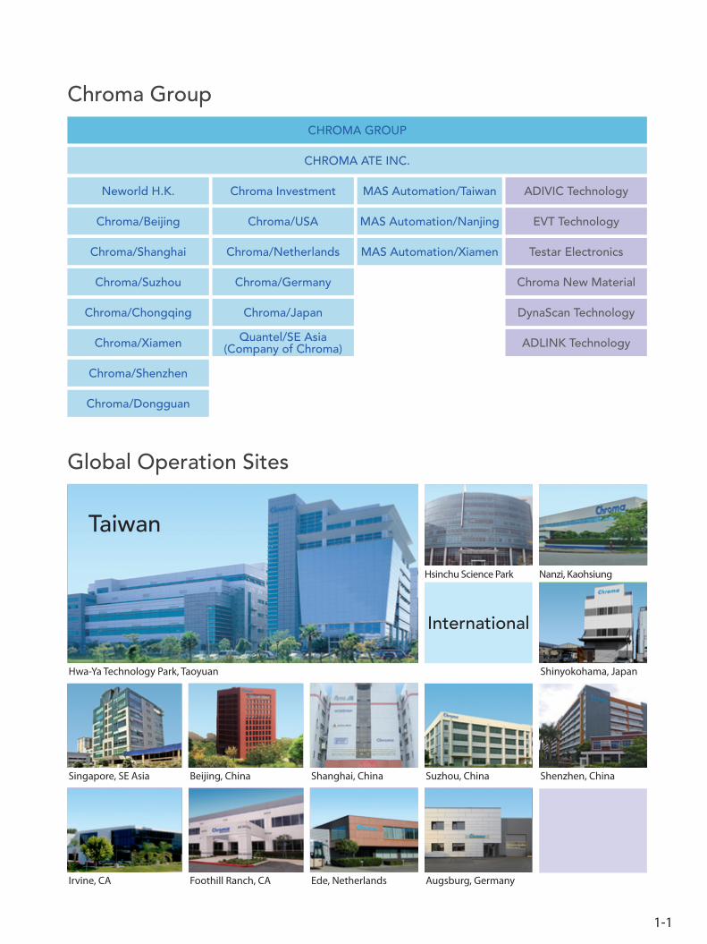
Chroma Group
Hsinchu Science Park Nanzi, Kaohsiung
Hwa-Ya Technology Park, Taoyuan
Taiwan
Shinyokohama, Japan
CHROMA GROUP
CHROMA ATE INC.
Neworld H.K. MAS Automation/Taiwan ADIVIC Technology
Chroma/Beijing
Chroma/Shanghai
Chroma/Suzhou
Chroma/Chongqing
Chroma/Xiamen
Chroma/Shenzhen
Chroma Investment
Chroma/USA
Chroma/Netherlands
Chroma/Japan
Chroma/Germany
Quantel/SE Asia(Company of Chroma)
MAS Automation/Nanjing
MAS Automation/Xiamen
EVT Technology
Chroma New Material
Testar Electronics
DynaScan Technology
ADLINK Technology
Chroma/Dongguan
International
Global Operation Sites
Foothill Ranch, CAIrvine, CA Ede, Netherlands Augsburg, Germany
Shenzhen, ChinaSuzhou, ChinaShanghai, ChinaBeijing, ChinaSingapore, SE Asia
Functional Index
New products are asterisked.
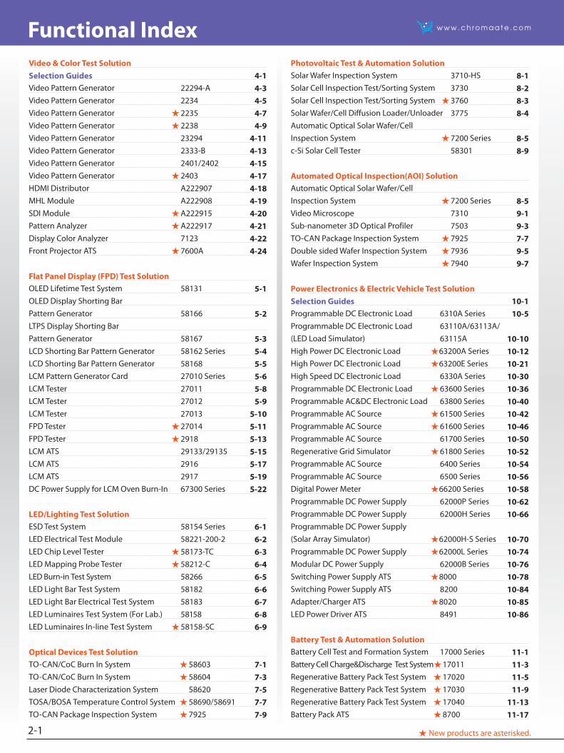
Photovoltaic Test & Automation SolutionSolar Wafer Inspection System 3710-HS 8-1Solar Cell Inspection Test/Sorting System 3730 8-2Solar Cell Inspection Test/Sorting System 3760 8-3Solar Wafer/Cell Diffusion Loader/Unloader 3775 8-4Automatic Optical Solar Wafer/CellInspection System 7200 Series 8-5c-Si Solar Cell Tester 58301 8-9
Automated Optical Inspection(AOI) SolutionAutomatic Optical Solar Wafer/CellInspection System 7200 Series 8-5Video Microscope 7310 9-1Sub-nanometer 3D Optical Profiler 7503 9-3TO-CAN Package Inspection System 7925 7-7Double sided Wafer Inspection System 7936 9-5Wafer Inspection System 7940 9-7
Power Electronics & Electric Vehicle Test SolutionSelection Guides 10-1Programmable DC Electronic Load 6310A Series 10-5Programmable DC Electronic Load 63110A/63113A/ (LED Load Simulator) 63115A 10-10High Power DC Electronic Load 63200A Series 10-12High Power DC Electronic Load 63200E Series 10-21High Speed DC Electronic Load 6330A Series 10-30Programmable DC Electronic Load 63600 Series 10-36Programmable AC&DC Electronic Load 63800 Series 10-40Programmable AC Source 61500 Series 10-42Programmable AC Source 61600 Series 10-46Programmable AC Source 61700 Series 10-50Regenerative Grid Simulator 61800 Series 10-52Programmable AC Source 6400 Series 10-54Programmable AC Source 6500 Series 10-56Digital Power Meter 66200 Series 10-58Programmable DC Power Supply 62000P Series 10-62Programmable DC Power Supply 62000H Series 10-66Programmable DC Power Supply(Solar Array Simulator) 62000H-S Series 10-70Programmable DC Power Supply 62000L Series 10-74Modular DC Power Supply 62000B Series 10-76Switching Power Supply ATS 8000 10-78Switching Power Supply ATS 8200 10-84Adapter/Charger ATS 8020 10-85LED Power Driver ATS 8491 10-86
Battery Test & Automation Solution Battery Cell Test and Formation System 17000 Series 11-1Battery Cell Charge&Discharge Test System17011 11-3Regenerative Battery Pack Test System 17020 11-5Regenerative Battery Pack Test System 17030 11-9Regenerative Battery Pack Test System 17040 11-13Battery Pack ATS 8700 11-17
Video & Color Test SolutionSelection Guides 4-1Video Pattern Generator 22294-A 4-3Video Pattern Generator 2234 4-5Video Pattern Generator 2235 4-7Video Pattern Generator 2238 4-9Video Pattern Generator 23294 4-11Video Pattern Generator 2333-B 4-13Video Pattern Generator 2401/2402 4-15Video Pattern Generator 2403 4-17HDMI Distributor A222907 4-18MHL Module A222908 4-19SDI Module A222915 4-20Pattern Analyzer A222917 4-21Display Color Analyzer 7123 4-22Front Projector ATS 7600A 4-24
Flat Panel Display (FPD) Test SolutionOLED Lifetime Test System 58131 5-1OLED Display Shorting BarPattern Generator 58166 5-2LTPS Display Shorting BarPattern Generator 58167 5-3LCD Shorting Bar Pattern Generator 58162 Series 5-4LCD Shorting Bar Pattern Generator 58168 5-5LCM Pattern Generator Card 27010 Series 5-6LCM Tester 27011 5-8LCM Tester 27012 5-9LCM Tester 27013 5-10FPD Tester 27014 5-11FPD Tester 2918 5-13LCM ATS 29133/29135 5-15LCM ATS 2916 5-17LCM ATS 2917 5-19DC Power Supply for LCM Oven Burn-In 67300 Series 5-22
LED/Lighting Test SolutionESD Test System 58154 Series 6-1LED Electrical Test Module 58221-200-2 6-2LED Chip Level Tester 58173-TC 6-3LED Mapping Probe Tester 58212-C 6-4LED Burn-in Test System 58266 6-5LED Light Bar Test System 58182 6-6LED Light Bar Electrical Test System 58183 6-7LED Luminaires Test System (For Lab.) 58158 6-8LED Luminaires In-line Test System 58158-SC 6-9
Optical Devices Test SolutionTO-CAN/CoC Burn In System 58603 7-1TO-CAN/CoC Burn In System 58604 7-3Laser Diode Characterization System 58620 7-5TOSA/BOSA Temperature Control System 58690/58691 7-7TO-CAN Package Inspection System 7925 7-9
2-1
Functional Index
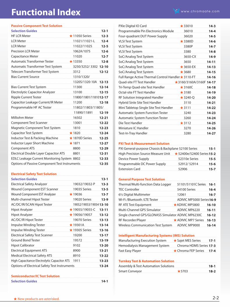
New products are asterisked.
PXIe Digital IO Card 33010 14-3Programmable Pin Electronics Module 36010 14-4Four-quadrant DUT Power Supply 36020 14-5VLSI Test System 3380D 14-6VLSI Test System 3380P 14-7VLSI Test System 3380 14-8SoC/Analog Test System 3650-CX 14-9SoC/Analog Test System 3650 14-11SoC/Analog Test System 3650-EX 14-13SoC/Analog Test System 3680 14-15Full Range Active Thermal Control Handler 3110-FT 14-16Quad-site FT Test Handler 3160/3160A/3160F 14-17Tri-Temp Quad-site Test Handler 3160C 14-18Octal-site FT Test Handler 3180 14-19RF Solution Integrated Handler 3240-Q 14-20Hybrid Sinle Site Test Handler 3110 14-21Mini Tabletop Single Site Test Handler 3111 14-22Automatic System Function Tester 3240 14-23Automatic System Function Tester 3260 14-24Die Test Handler 3112 14-25Miniature IC Handler 3270 14-26Test-In-Tray Handler 3280 14-27
PXI Test & Measurement SolutionPXI General-purpose Chassis & Backplane 52100 Series 15-1High Precision Source Measure Unit 52400e/52400 Series 15-2Device Power Supply 52310e Series 15-5Programmable DC Power Supply 52912/ 52914 15-6Extension Card 52906 15-7
General Purpose Test SolutionThermal/Multi-function Data Logger 51101/51101C Series 16-1TEC Controller 54100 Series 16-46½ Digital Multimeter 12061 16-7Wi-Fi /Bluetooth /LTE Tester ADIVIC MP5000 Series16-9RF ATE Test Equipment ADIVIC MP5800 16-10Multi-Channel GPS Simulator ADIVIC MP6220 16-11Single channel GPS/GLONASS Simulator ADIVIC MP6230C 16-12RF Recorder/Player ADIVIC MP7 Series 16-13Wireless Communication Test System ADIVIC MP9000 16-14
Intelligent Manufacturing Systems (IMS) SolutionManufacturing Execution System Sajet MES Series 17-1Hemodialysis Management System Chroma HDMS Series 17-3Fast Easy Player Chroma FEP Series 17-4
Turnkey Test & Automation SolutionAssembly & Test Automation Solutions 18-1Smart Conveyor 5703 18-2
Passive Component Test SolutionSelection Guides 12-1HF LCR Meter 11050 Series 12-3LCR Meter 11021/11021-L 12-4LCR Meter 11022/11025 12-5Precision LCR Meter 1062A/1075 12-6Capacitance Meter 11020 12-7Automatic Transformer Tester 13350 12-8Automatic Transformer Test System 3250/3252/ 3302 12-10Telecom Transformer Test System 3312 12-12Bias Current Source 1310/1320/ 1320S/1320-10A 12-13Bias Current Test System 11300 12-14Electrolytic Capacitor Analyzer 13100 12-15Ripple Current Tester 11800/11801/11810 12-17Capacitor Leakage Current/IR Meter 11200 12-18Programmable HF AC Tester 11802/11803/11805/
11890/11891 12-19Milliohm Meter 16502 12-21Component Test Scanner 13001 12-22Magnetic Component Test System 1810 12-23Capacitor Test System 1820 12-24Inductor Test & Packing Machine 1870D Series 12-25Inductor Layer Short Machine 1871 12-27Component ATS 8800 12-29Electrical Double Layer Capacitor ATS 8801 12-31EDLC Leakage Current Monitoring System 8802 12-33Options of Passive Component Test Instruments 12-35
Electrical Safety Test SolutionSelection Guides 13-1Electrical Safety Analyzer 19032/19032-P 13-3Wound Component EST Scanner 19035 Series 13-5Wound Component EST Analyzer 19036 13-7Multi-channel Hipot Tester 19020 Series 13-9AC/DC/IR/SCAN Hipot Tester 19052/19053/19054 13-10Hipot Analyzer 19055/19055-C 13-11Hipot Analyzer 19056/19057 13-12AC/DC/IR Hipot Tester 19070 Series 13-13Impulse Winding Tester 19301A 13-14Impulse Winding Tester 19305 Series 13-16Electrical Safety Test Scanner 19200 13-17Ground Bond Tester 19572 13-19Hipot Calibrator 9102 13-20Electrical Equipment ATS 8900 13-21Medical Electrical Safety ATS 8910 13-22High Capacitance Electrolytic Capacitor ATS 1911 13-23Options of Electrical Safety Test Instruments 13-24
Semiconductor/IC Test Solution Selection Guides 14-1
2-2
Model Index
New products are asterisked.2-3
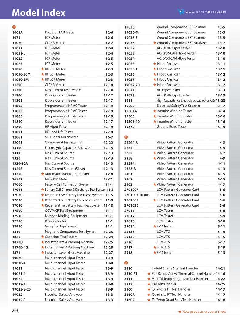
19035 Wound Component EST Scanner 13-519035-M Wound Component EST Scanner 13-519035-S Wound Component EST Scanner 13-519036 Wound Component EST Analyzer 13-719052 AC/DC/IR Hipot Tester 13-1019053 AC/DC/SCAN Hipot Tester 13-1019054 AC/DC/SCAN Hipot Tester 13-1019055 Hipot Analyzer 13-1119055-C Hipot Analyzer 13-1119056 Hipot Analyzer 13-1219057 Hipot Analyzer 13-1219057-20 Hipot Analyzer 13-1219071 AC Hipot Tester 13-1319073 AC/DC/IR Hipot Tester 13-131911 High Capacitance Electrolytic Capacitor ATS 13-2319200 Electrical Safety Test Scanner 13-1719301A Impulse Winding Tester 13-1419305 Impulse Winding Tester 13-1619305-10 Impulse Winding Tester 13-1619572 Ground Bond Tester 13-19
➋
22294-A Video Pattern Generator 4-32234 Video Pattern Generator 4-52235 Video Pattern Generator 4-72238 Video Pattern Generator 4-923294 Video Pattern Generator 4-112333-B Video Pattern Generator 4-132401 Video Pattern Generator 4-152402 Video Pattern Generator 4-152403 Video Pattern Generator 4-172701007 LCM Pattern Generator Card 5-62701007 10 bit LCM Pattern Generator Card 5-62701009 LCM Pattern Generator Card 5-62701020 LCM Pattern Generator Card 5-627011 LCM Tester 5-827012 LCM Tester 5-927013 LCM Tester 5-1027014 FPD Tester 5-1129133 LCM ATS 5-1529135 LCM ATS 5-152916 LCM ATS 5-172917 LCM ATS 5-192918 FPD Tester 5-13
➌
3110 Hybrid Single Site Test Handler 14-213110-FT Full Range Active Thermal Control Handler 14-163111 Mini Tabletop Single Site Test Handler 14-223112 Die Test Handler 14-253160 Quad-site FT Test Handler 14-173160A Quad-site FT Test Handler 14-173160C Tri-Temp Quad Sites Test Handler 14-18
➊
1062A Precision LCR Meter 12-61075 LCR Meter 12-611020 CLC/IR Meter 12-711021 LCR Meter 12-411021-L LCR Meter 12-411022 LCR Meter 12-5 11025 LCR Meter 12-5 11050 HF LCR Meter 12-3 11050-30M HF LCR Meter 12-3 11050-5M HF LCR Meter 12-3 11200 CLC/IR Meter 12-1811300 Bias Current Test System 12-1411800 Ripple Current Tester 12-17 11801 Ripple Current Tester 12-17 11802 Programmable HF AC Tester 12-1911803 Programmable HF AC Tester 12-1911805 Programmable HF AC Tester 12-1911810 Ripple Current Tester 12-1711890 HF Hipot Tester 12-1911891 HF Load Life Tester 12-1912061 6½ Digital Multimeter 16-713001 Component Test Scanner 12-2213100 Electrolytic Capacitor Analyzer 12-15 1310 Bias Current Source 12-13 1320 Bias Current Source 12-13 1320-10A Bias Current Source 12-13 1320S Bias Current Source (Slave) 12-1313350 Automatic Transformer Tester 12-816502 Milliohm Meter 12-21 17000 Battery Cell Formation System 11-117011 Battery Cell Charge & Discharge Test System11-317020 Regenerative Battery Pack Test System 11-517030 Regenerative Battery Pack Test System 11-917040 Regenerative Battery Pack Test System 11-1317800 OCV/ACR Test Equipment 11-117910 Barcode Binding Equipment 11-117920 Rework Sorter 11-117930 Grouping Equipment 11-11810 Magnetic Component Test System 12-231820 Capacitor Test System 12-241870D Inductor Test & Packing Machine 12-251870D-12 Inductor Test & Packing Machine 12-251871 Inductor Layer Short Machine 12-2719020 Multi-channel Hipot Tester 13-919020-4 Multi-channel Hipot Tester 13-919021 Multi-channel Hipot Tester 13-919021-4 Multi-channel Hipot Tester 13-919022 Multi-channel Hipot Tester 13-919022-4 Multi-channel Hipot Tester 13-919023-8-20 Multi-channel Hipot Tester 13-919032 Electrical Safety Analyzer 13-319032-P Electrical Safety Analyzer 13-3
Model Index
New products are asterisked. 2-4
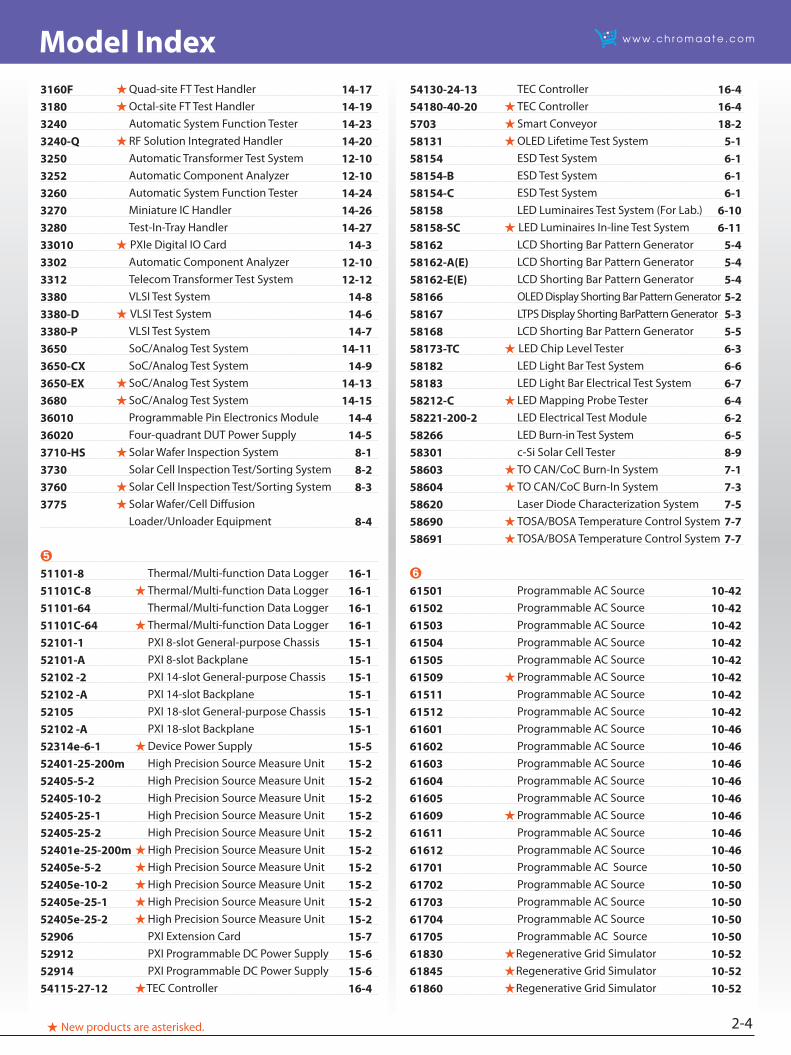
3160F Quad-site FT Test Handler 14-173180 Octal-site FT Test Handler 14-193240 Automatic System Function Tester 14-233240-Q RF Solution Integrated Handler 14-203250 Automatic Transformer Test System 12-103252 Automatic Component Analyzer 12-103260 Automatic System Function Tester 14-243270 Miniature IC Handler 14-263280 Test-In-Tray Handler 14-2733010 PXIe Digital IO Card 14-33302 Automatic Component Analyzer 12-10 3312 Telecom Transformer Test System 12-123380 VLSI Test System 14-83380-D VLSI Test System 14-63380-P VLSI Test System 14-73650 SoC/Analog Test System 14-113650-CX SoC/Analog Test System 14-93650-EX SoC/Analog Test System 14-133680 SoC/Analog Test System 14-1536010 Programmable Pin Electronics Module 14-436020 Four-quadrant DUT Power Supply 14-53710-HS Solar Wafer Inspection System 8-13730 Solar Cell Inspection Test/Sorting System 8-23760 Solar Cell Inspection Test/Sorting System 8-33775 Solar Wafer/Cell Diffusion Loader/Unloader Equipment 8-4
➎
51101-8 Thermal/Multi-function Data Logger 16-151101C-8 Thermal/Multi-function Data Logger 16-151101-64 Thermal/Multi-function Data Logger 16-151101C-64 Thermal/Multi-function Data Logger 16-152101-1 PXI 8-slot General-purpose Chassis 15-152101-A PXI 8-slot Backplane 15-152102 -2 PXI 14-slot General-purpose Chassis 15-152102 -A PXI 14-slot Backplane 15-152105 PXI 18-slot General-purpose Chassis 15-152102 -A PXI 18-slot Backplane 15-152314e-6-1 Device Power Supply 15-552401-25-200m High Precision Source Measure Unit 15-252405-5-2 High Precision Source Measure Unit 15-252405-10-2 High Precision Source Measure Unit 15-252405-25-1 High Precision Source Measure Unit 15-252405-25-2 High Precision Source Measure Unit 15-252401e-25-200m High Precision Source Measure Unit 15-252405e-5-2 High Precision Source Measure Unit 15-252405e-10-2 High Precision Source Measure Unit 15-252405e-25-1 High Precision Source Measure Unit 15-252405e-25-2 High Precision Source Measure Unit 15-252906 PXI Extension Card 15-752912 PXI Programmable DC Power Supply 15-652914 PXI Programmable DC Power Supply 15-654115-27-12 TEC Controller 16-4
54130-24-13 TEC Controller 16-454180-40-20 TEC Controller 16-45703 Smart Conveyor 18-258131 OLED Lifetime Test System 5-158154 ESD Test System 6-158154-B ESD Test System 6-158154-C ESD Test System 6-158158 LED Luminaires Test System (For Lab.) 6-1058158-SC LED Luminaires In-line Test System 6-1158162 LCD Shorting Bar Pattern Generator 5-458162-A(E) LCD Shorting Bar Pattern Generator 5-458162-E(E) LCD Shorting Bar Pattern Generator 5-458166 OLED Display Shorting Bar Pattern Generator 5-258167 LTPS Display Shorting BarPattern Generator 5-358168 LCD Shorting Bar Pattern Generator 5-558173-TC LED Chip Level Tester 6-358182 LED Light Bar Test System 6-658183 LED Light Bar Electrical Test System 6-758212-C LED Mapping Probe Tester 6-458221-200-2 LED Electrical Test Module 6-258266 LED Burn-in Test System 6-558301 c-Si Solar Cell Tester 8-958603 TO CAN/CoC Burn-In System 7-158604 TO CAN/CoC Burn-In System 7-358620 Laser Diode Characterization System 7-558690 TOSA/BOSA Temperature Control System 7-758691 TOSA/BOSA Temperature Control System 7-7
➏
61501 Programmable AC Source 10-4261502 Programmable AC Source 10-4261503 Programmable AC Source 10-4261504 Programmable AC Source 10-4261505 Programmable AC Source 10-4261509 Programmable AC Source 10-4261511 Programmable AC Source 10-4261512 Programmable AC Source 10-4261601 Programmable AC Source 10-4661602 Programmable AC Source 10-4661603 Programmable AC Source 10-4661604 Programmable AC Source 10-4661605 Programmable AC Source 10-4661609 Programmable AC Source 10-4661611 Programmable AC Source 10-4661612 Programmable AC Source 10-4661701 Programmable AC Source 10-5061702 Programmable AC Source 10-5061703 Programmable AC Source 10-5061704 Programmable AC Source 10-5061705 Programmable AC Source 10-5061830 Regenerative Grid Simulator 10-5261845 Regenerative Grid Simulator 10-5261860 Regenerative Grid Simulator 10-52
Model Index
New products are asterisked.2-5
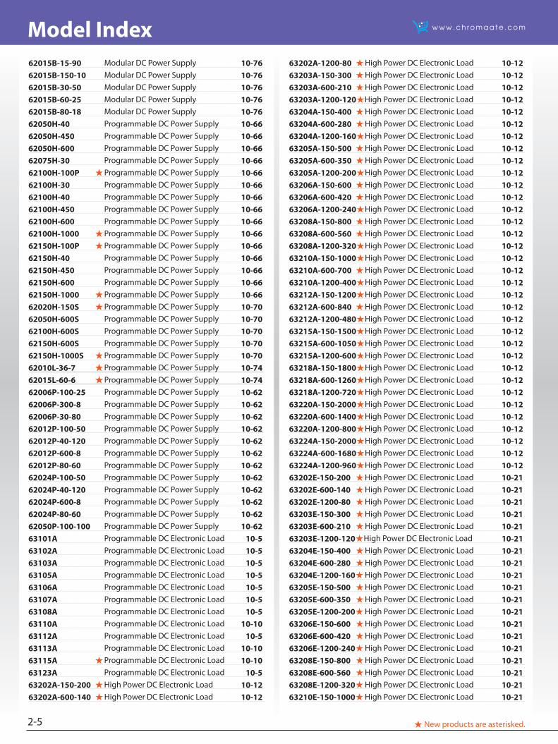
62015B-15-90 Modular DC Power Supply 10-7662015B-150-10 Modular DC Power Supply 10-7662015B-30-50 Modular DC Power Supply 10-7662015B-60-25 Modular DC Power Supply 10-7662015B-80-18 Modular DC Power Supply 10-7662050H-40 Programmable DC Power Supply 10-6662050H-450 Programmable DC Power Supply 10-6662050H-600 Programmable DC Power Supply 10-6662075H-30 Programmable DC Power Supply 10-6662100H-100P Programmable DC Power Supply 10-6662100H-30 Programmable DC Power Supply 10-6662100H-40 Programmable DC Power Supply 10-6662100H-450 Programmable DC Power Supply 10-6662100H-600 Programmable DC Power Supply 10-6662100H-1000 Programmable DC Power Supply 10-6662150H-100P Programmable DC Power Supply 10-6662150H-40 Programmable DC Power Supply 10-6662150H-450 Programmable DC Power Supply 10-6662150H-600 Programmable DC Power Supply 10-6662150H-1000 Programmable DC Power Supply 10-6662020H-150S Programmable DC Power Supply 10-7062050H-600S Programmable DC Power Supply 10-7062100H-600S Programmable DC Power Supply 10-7062150H-600S Programmable DC Power Supply 10-7062150H-1000S Programmable DC Power Supply 10-7062010L-36-7 Programmable DC Power Supply 10-7462015L-60-6 Programmable DC Power Supply 10-7462006P-100-25 Programmable DC Power Supply 10-6262006P-300-8 Programmable DC Power Supply 10-6262006P-30-80 Programmable DC Power Supply 10-6262012P-100-50 Programmable DC Power Supply 10-6262012P-40-120 Programmable DC Power Supply 10-6262012P-600-8 Programmable DC Power Supply 10-6262012P-80-60 Programmable DC Power Supply 10-6262024P-100-50 Programmable DC Power Supply 10-6262024P-40-120 Programmable DC Power Supply 10-6262024P-600-8 Programmable DC Power Supply 10-6262024P-80-60 Programmable DC Power Supply 10-6262050P-100-100 Programmable DC Power Supply 10-6263101A Programmable DC Electronic Load 10-563102A Programmable DC Electronic Load 10-563103A Programmable DC Electronic Load 10-563105A Programmable DC Electronic Load 10-563106A Programmable DC Electronic Load 10-563107A Programmable DC Electronic Load 10-563108A Programmable DC Electronic Load 10-563110A Programmable DC Electronic Load 10-1063112A Programmable DC Electronic Load 10-563113A Programmable DC Electronic Load 10-1063115A Programmable DC Electronic Load 10-1063123A Programmable DC Electronic Load 10-563202A-150-200 High Power DC Electronic Load 10-1263202A-600-140 High Power DC Electronic Load 10-12
63202A-1200-80 High Power DC Electronic Load 10-1263203A-150-300 High Power DC Electronic Load 10-1263203A-600-210 High Power DC Electronic Load 10-1263203A-1200-120High Power DC Electronic Load 10-1263204A-150-400 High Power DC Electronic Load 10-1263204A-600-280 High Power DC Electronic Load 10-1263204A-1200-160 High Power DC Electronic Load 10-1263205A-150-500 High Power DC Electronic Load 10-1263205A-600-350 High Power DC Electronic Load 10-1263205A-1200-200 High Power DC Electronic Load 10-1263206A-150-600 High Power DC Electronic Load 10-1263206A-600-420 High Power DC Electronic Load 10-1263206A-1200-240 High Power DC Electronic Load 10-1263208A-150-800 High Power DC Electronic Load 10-1263208A-600-560 High Power DC Electronic Load 10-1263208A-1200-320 High Power DC Electronic Load 10-1263210A-150-1000 High Power DC Electronic Load 10-1263210A-600-700 High Power DC Electronic Load 10-1263210A-1200-400 High Power DC Electronic Load 10-1263212A-150-1200 High Power DC Electronic Load 10-1263212A-600-840 High Power DC Electronic Load 10-1263212A-1200-480 High Power DC Electronic Load 10-1263215A-150-1500 High Power DC Electronic Load 10-1263215A-600-1050 High Power DC Electronic Load 10-1263215A-1200-600 High Power DC Electronic Load 10-1263218A-150-1800 High Power DC Electronic Load 10-1263218A-600-1260 High Power DC Electronic Load 10-1263218A-1200-720 High Power DC Electronic Load 10-1263220A-150-2000 High Power DC Electronic Load 10-1263220A-600-1400 High Power DC Electronic Load 10-1263220A-1200-800 High Power DC Electronic Load 10-1263224A-150-2000 High Power DC Electronic Load 10-1263224A-600-1680 High Power DC Electronic Load 10-1263224A-1200-960 High Power DC Electronic Load 10-1263202E-150-200 High Power DC Electronic Load 10-2163202E-600-140 High Power DC Electronic Load 10-2163202E-1200-80 High Power DC Electronic Load 10-2163203E-150-300 High Power DC Electronic Load 10-2163203E-600-210 High Power DC Electronic Load 10-2163203E-1200-120High Power DC Electronic Load 10-2163204E-150-400 High Power DC Electronic Load 10-2163204E-600-280 High Power DC Electronic Load 10-2163204E-1200-160 High Power DC Electronic Load 10-2163205E-150-500 High Power DC Electronic Load 10-2163205E-600-350 High Power DC Electronic Load 10-2163205E-1200-200 High Power DC Electronic Load 10-2163206E-150-600 High Power DC Electronic Load 10-2163206E-600-420 High Power DC Electronic Load 10-2163206E-1200-240 High Power DC Electronic Load 10-2163208E-150-800 High Power DC Electronic Load 10-2163208E-600-560 High Power DC Electronic Load 10-2163208E-1200-320 High Power DC Electronic Load 10-2163210E-150-1000 High Power DC Electronic Load 10-21
Model Index
New products are asterisked. 2-6
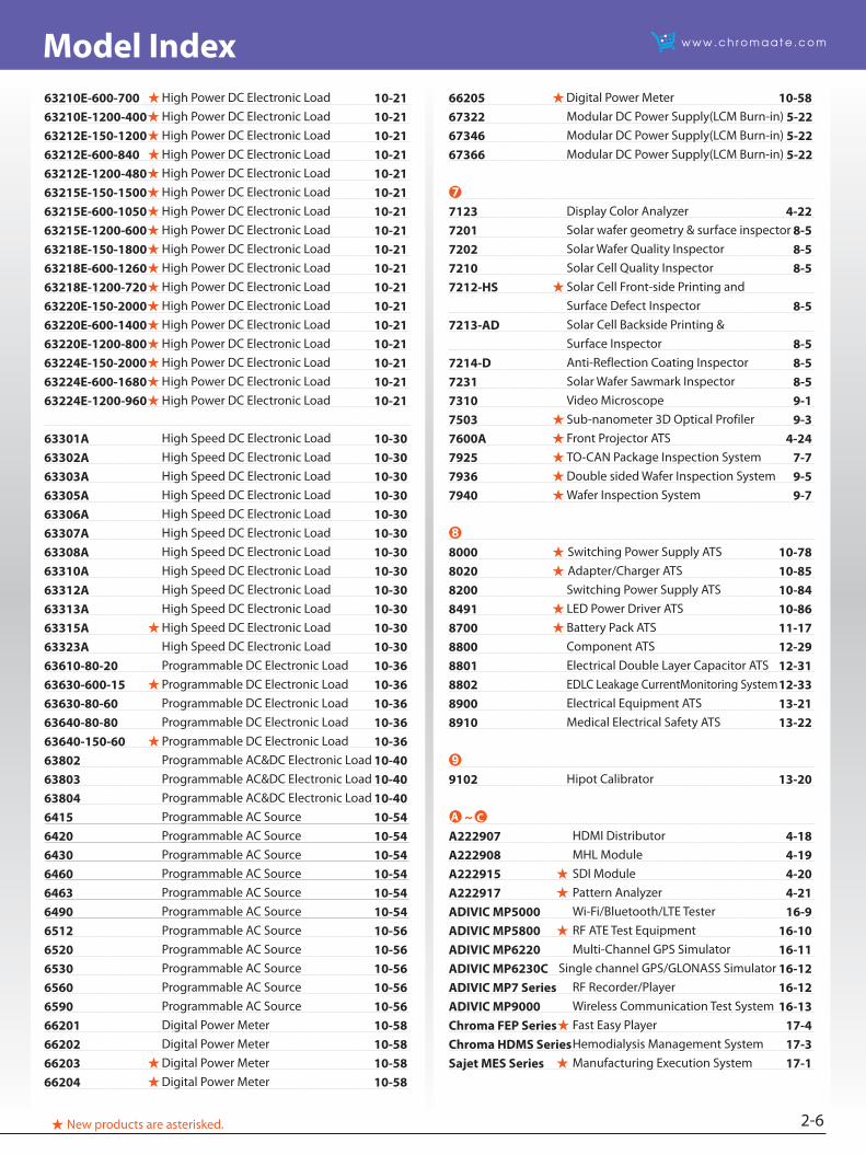
63210E-600-700 High Power DC Electronic Load 10-2163210E-1200-400 High Power DC Electronic Load 10-2163212E-150-1200 High Power DC Electronic Load 10-2163212E-600-840 High Power DC Electronic Load 10-2163212E-1200-480 High Power DC Electronic Load 10-2163215E-150-1500 High Power DC Electronic Load 10-2163215E-600-1050 High Power DC Electronic Load 10-2163215E-1200-600 High Power DC Electronic Load 10-2163218E-150-1800 High Power DC Electronic Load 10-2163218E-600-1260 High Power DC Electronic Load 10-2163218E-1200-720 High Power DC Electronic Load 10-2163220E-150-2000 High Power DC Electronic Load 10-2163220E-600-1400 High Power DC Electronic Load 10-2163220E-1200-800 High Power DC Electronic Load 10-2163224E-150-2000 High Power DC Electronic Load 10-2163224E-600-1680 High Power DC Electronic Load 10-2163224E-1200-960 High Power DC Electronic Load 10-21
63301A High Speed DC Electronic Load 10-3063302A High Speed DC Electronic Load 10-3063303A High Speed DC Electronic Load 10-3063305A High Speed DC Electronic Load 10-3063306A High Speed DC Electronic Load 10-3063307A High Speed DC Electronic Load 10-3063308A High Speed DC Electronic Load 10-3063310A High Speed DC Electronic Load 10-3063312A High Speed DC Electronic Load 10-3063313A High Speed DC Electronic Load 10-3063315A High Speed DC Electronic Load 10-3063323A High Speed DC Electronic Load 10-3063610-80-20 Programmable DC Electronic Load 10-3663630-600-15 Programmable DC Electronic Load 10-3663630-80-60 Programmable DC Electronic Load 10-3663640-80-80 Programmable DC Electronic Load 10-3663640-150-60 Programmable DC Electronic Load 10-3663802 Programmable AC&DC Electronic Load 10-4063803 Programmable AC&DC Electronic Load 10-4063804 Programmable AC&DC Electronic Load 10-406415 Programmable AC Source 10-546420 Programmable AC Source 10-546430 Programmable AC Source 10-546460 Programmable AC Source 10-546463 Programmable AC Source 10-546490 Programmable AC Source 10-546512 Programmable AC Source 10-566520 Programmable AC Source 10-566530 Programmable AC Source 10-566560 Programmable AC Source 10-566590 Programmable AC Source 10-5666201 Digital Power Meter 10-5866202 Digital Power Meter 10-5866203 Digital Power Meter 10-5866204 Digital Power Meter 10-58
66205 Digital Power Meter 10-5867322 Modular DC Power Supply(LCM Burn-in) 5-2267346 Modular DC Power Supply(LCM Burn-in) 5-2267366 Modular DC Power Supply(LCM Burn-in) 5-22
➐
7123 Display Color Analyzer 4-227201 Solar wafer geometry & surface inspector 8-57202 Solar Wafer Quality Inspector 8-57210 Solar Cell Quality Inspector 8-57212-HS Solar Cell Front-side Printing and Surface Defect Inspector 8-57213-AD Solar Cell Backside Printing & Surface Inspector 8-57214-D Anti-Reflection Coating Inspector 8-57231 Solar Wafer Sawmark Inspector 8-57310 Video Microscope 9-17503 Sub-nanometer 3D Optical Profiler 9-37600A Front Projector ATS 4-247925 TO-CAN Package Inspection System 7-77936 Double sided Wafer Inspection System 9-57940 Wafer Inspection System 9-7
➑
8000 Switching Power Supply ATS 10-788020 Adapter/Charger ATS 10-858200 Switching Power Supply ATS 10-848491 LED Power Driver ATS 10-868700 Battery Pack ATS 11-178800 Component ATS 12-298801 Electrical Double Layer Capacitor ATS 12-318802 EDLC Leakage CurrentMonitoring System 12-338900 Electrical Equipment ATS 13-218910 Medical Electrical Safety ATS 13-22
➒
9102 Hipot Calibrator 13-20
~A222907 HDMI Distributor 4-18A222908 MHL Module 4-19A222915 SDI Module 4-20A222917 Pattern Analyzer 4-21ADIVIC MP5000 Wi-Fi/Bluetooth/LTE Tester 16-9ADIVIC MP5800 RF ATE Test Equipment 16-10ADIVIC MP6220 Multi-Channel GPS Simulator 16-11ADIVIC MP6230C Single channel GPS/GLONASS Simulator 16-12ADIVIC MP7 Series RF Recorder/Player 16-12ADIVIC MP9000 Wireless Communication Test System 16-13Chroma FEP Series Fast Easy Player 17-4Chroma HDMS Series Hemodialysis Management System 17-3Sajet MES Series Manufacturing Execution System 17-1
A C
3-1
New Products
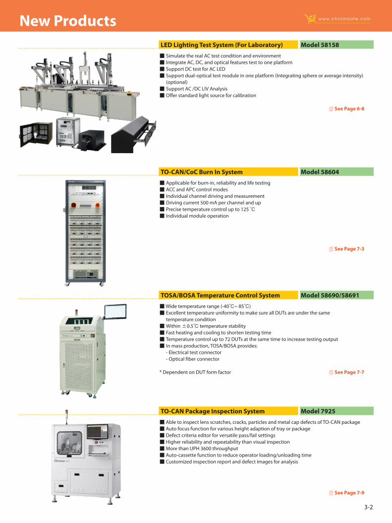
Support 8K SHV (Super Hi-Vision 7680x4320 / 8192x4320) Support full 8K scrolling function Independent signal and power module design Dual-core graphics processing architecture - Increase graphics and data transmission performance - 8K Super Hi-Vision images switch in less than 200ms Support 6/8/10/12 bits color depth (12 bit only in LUT mode)
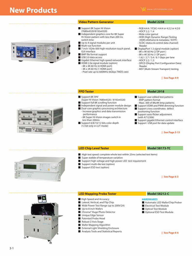
Support 8K Super Hi-Vision (7680x4320/8192x4320) Independent graphics core for 8K Super Hi-Vision pattern with less than 200 ms switch time Up to 4 signal modules per unit Multi-out function 7 inch 1024x 600 high-resolution touch panel, GUI interface BMP file format support USB 3.0 data access Gigabit Ethernet high-speed network interface HDMI 2.0a signal module (option) - 8K x 4K 60 Hz (4 HDMI port) - 4K x 2K 60 Hz (1 HDMI port) - Pixel rate up to 600MHz (6Gbps TMDS rate)
FPD Tester Model 2918
4 See Page 5-13
4 See Page 4-9
Support user edited test patterns - BMP pattern format - Maxi. 300 of 8Kx4K bmp patterns Support VDIM and PWM dimming function Support cross coordinates defect positioning function Support auto flicker adjustment (with A712306) Support gigabit Ethernet control interface Support USB port for data update
- RGB 4:4:4 / YCbCr 4:4:4 or 4:2:2 or 4:2:0 - HDCP 2.2 / 1.4 - Wide color gamut - HDR (High Dynamic Range) Testing (HDR infoframe & metadata / EOTF) - SCDC (status & control data channel) Reader DisplayPort 1.3 signal module (option) - 8K x 4K 60 Hz (2 DP port ) - 8K x 4K 30 Hz (1 DP port ) - 1.62 / 2.7 / 5.4 / 8.1 Gbps per lane - HDCP 2.2 / 1.3 - DPCD (Display Port Configuration Data) Reader - MST (Multi-Stream Transport) testing
Video Pattern Generator Model 2238
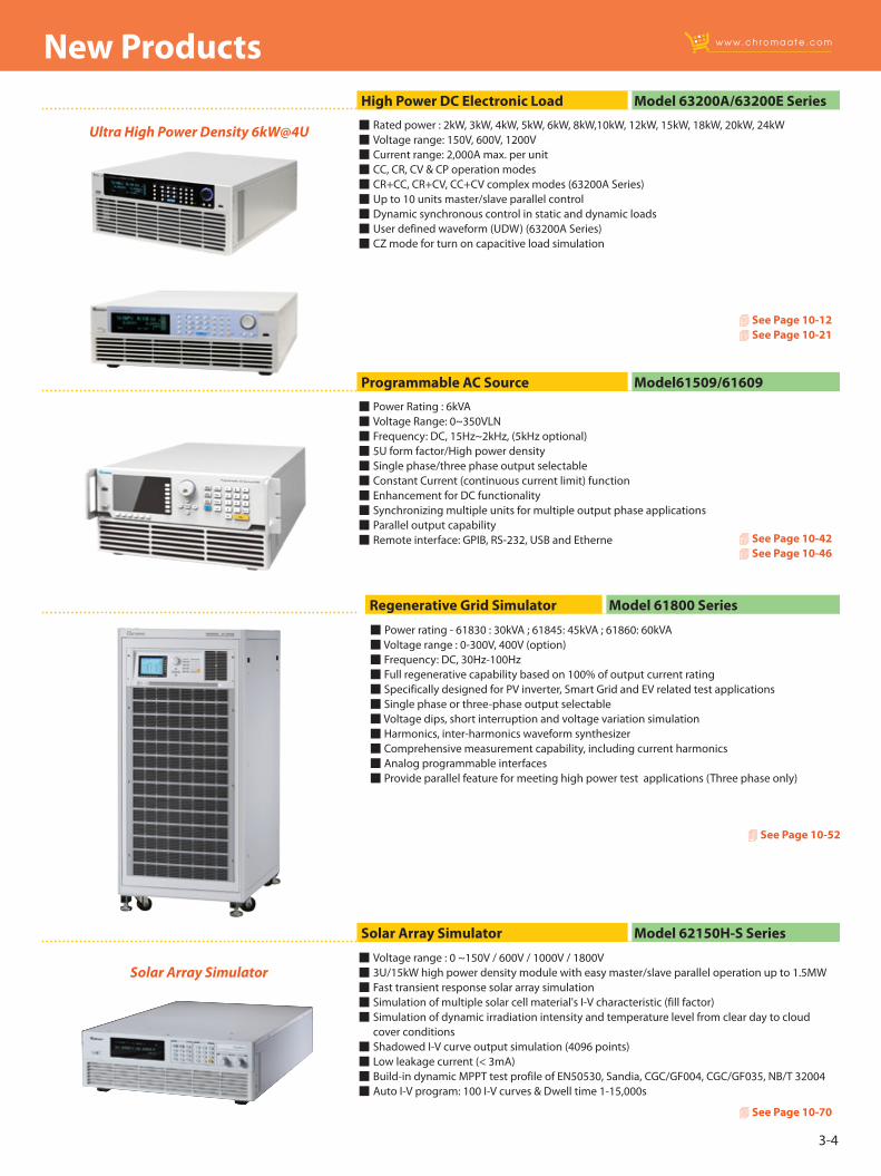
High Speed and Accuracy Lateral, Vertical, and Flip Chip Wide Power Test Range (up to 200V/2A) Up to 8 inch Wafers Chroma® Huge Photo Detector Unique Edge Sensor Patented Probe Head Robust Z-Axis Stage Wafer Mapping Algorithm External Light Shielding Enclosure Analysis Tools and Statistical Reports
LED Mapping Probe Tester Model 58212-C
4 See Page 6-4
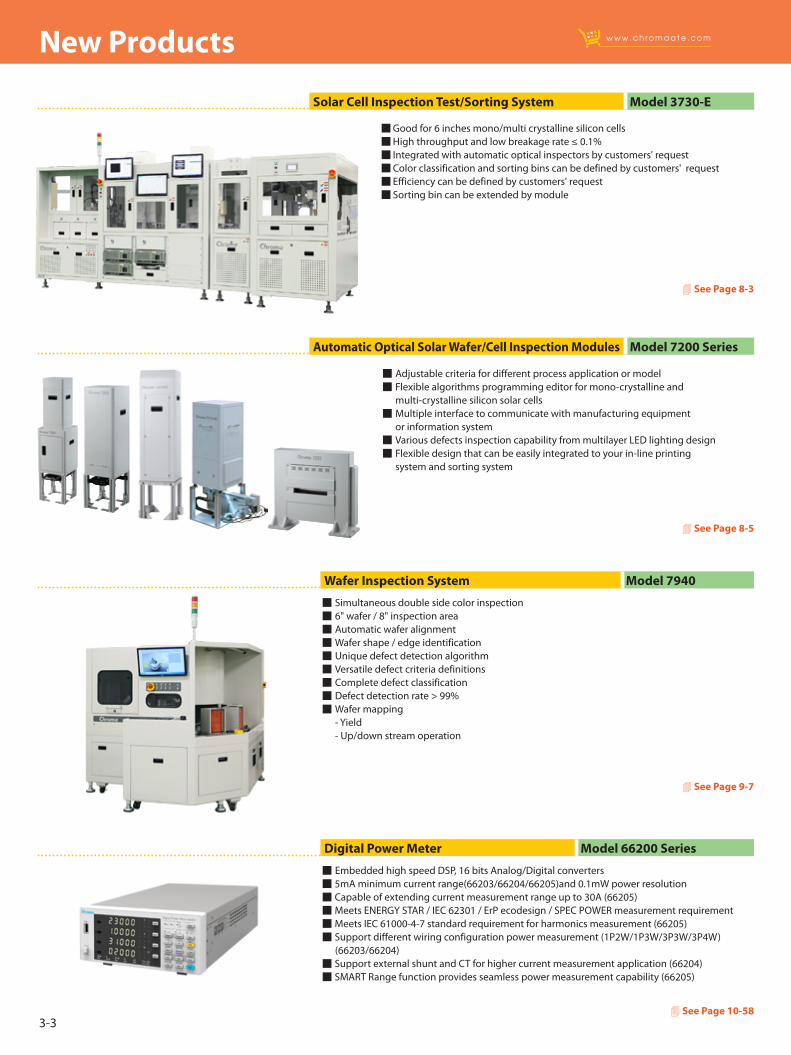
High test speed: complete whole test within 25ms (selected test items) Super statble of temperature variation Support high voltage and high power LED test requirement Support multi-die test (option) Support ESD test (option)
LED Chip Level Tester Model 58173-TC
4 See Page 6-3
HARDWARES Automatic LED Wafer/Chip Prober Electrical Test Module Optical Test Module Optional ESD Test Module
3-2
New Products
Simulate the real AC test condition and environment Integrate AC, DC, and optical features test to one platform Support DC test for AC LED Support dual-optical test module in one platform (Integrating sphere or average intensity)
(optional) Support AC /DC LIV Analysis Offer standard light source for calibration
LED Lighting Test System (For Laboratory) Model 58158
4 See Page 6-8
Able to inspect lens scratches, cracks, particles and metal cap defects of TO-CAN package Auto focus function for various height adaption of tray or package Defect criteria editor for versatile pass/fail settings Higher reliability and repeatability than visual inspection More than UPH 3600 throughput Auto-cassette function to reduce operator loading/unloading time Customized inspection report and defect images for analysis
Wide temperature range (-40~ 85) Excellent temperature uniformity to make sure all DUTs are under the same temperature condition Within ±0.5 temperature stability Fast heating and cooling to shorten testing time Temperature control up to 72 DUTs at the same time to increase testing output In mass production, TOSA/BOSA provides: - Electrical test connector - Optical fiber connector
* Dependent on DUT form factor
Applicable for burn-in, reliability and life testing ACC and APC control modes Individual channel driving and measurement Driving current 500 mA per channel and up Precise temperature control up to 125 Individual module operation
TO-CAN Package Inspection System Model 7925
TOSA/BOSA Temperature Control System Model 58690/58691
TO-CAN/CoC Burn In System Model 58604
4 See Page 7-9
4 See Page 7-7
4 See Page 7-3
3-3
New Products
Solar Cell Inspection Test/Sorting System Model 3730-E
4 See Page 8-3
Adjustable criteria for different process application or model Flexible algorithms programming editor for mono-crystalline and multi-crystalline silicon solar cells Multiple interface to communicate with manufacturing equipment or information system Various defects inspection capability from multilayer LED lighting design Flexible design that can be easily integrated to your in-line printing system and sorting system
Automatic Optical Solar Wafer/Cell Inspection Modules Model 7200 Series
4 See Page 8-5
Simultaneous double side color inspection 6" wafer / 8" inspection area Automatic wafer alignment Wafer shape / edge identification Unique defect detection algorithm Versatile defect criteria definitions Complete defect classification Defect detection rate > 99% Wafer mapping - Yield - Up/down stream operation
Wafer Inspection System Model 7940
4 See Page 9-7
Embedded high speed DSP, 16 bits Analog/Digital converters 5mA minimum current range(66203/66204/66205)and 0.1mW power resolution Capable of extending current measurement range up to 30A (66205) Meets ENERGY STAR / IEC 62301 / ErP ecodesign / SPEC POWER measurement requirement Meets IEC 61000-4-7 standard requirement for harmonics measurement (66205) Support different wiring configuration power measurement (1P2W/1P3W/3P3W/3P4W) (66203/66204) Support external shunt and CT for higher current measurement application (66204) SMART Range function provides seamless power measurement capability (66205)
Digital Power Meter Model 66200 Series
4 See Page 10-58
Good for 6 inches mono/multi crystalline silicon cells High throughput and low breakage rate ≤ 0.1% Integrated with automatic optical inspectors by customers' request Color classification and sorting bins can be defined by customers' request Efficiency can be defined by customers' request Sorting bin can be extended by module
3-4
New Products
Voltage range : 0 ~150V / 600V / 1000V / 1800V 3U/15kW high power density module with easy master/slave parallel operation up to 1.5MW Fast transient response solar array simulation Simulation of multiple solar cell material's I-V characteristic (fill factor) Simulation of dynamic irradiation intensity and temperature level from clear day to cloud cover conditions Shadowed I-V curve output simulation (4096 points) Low leakage current (< 3mA) Build-in dynamic MPPT test profile of EN50530, Sandia, CGC/GF004, CGC/GF035, NB/T 32004 Auto I-V program: 100 I-V curves & Dwell time 1-15,000s
Solar Array Simulator Model 62150H-S Series
4 See Page 10-70
Solar Array Simulator
Ultra High Power Density 6kW@4U Rated power : 2kW, 3kW, 4kW, 5kW, 6kW, 8kW,10kW, 12kW, 15kW, 18kW, 20kW, 24kW Voltage range: 150V, 600V, 1200V Current range: 2,000A max. per unit CC, CR, CV & CP operation modes CR+CC, CR+CV, CC+CV complex modes (63200A Series) Up to 10 units master/slave parallel control Dynamic synchronous control in static and dynamic loads User defined waveform (UDW) (63200A Series) CZ mode for turn on capacitive load simulation
Power Rating : 6kVA Voltage Range: 0~350VLN Frequency: DC, 15Hz~2kHz, (5kHz optional) 5U form factor/High power density Single phase/three phase output selectable Constant Current (continuous current limit) function Enhancement for DC functionality Synchronizing multiple units for multiple output phase applications Parallel output capability Remote interface: GPIB, RS-232, USB and Etherne
High Power DC Electronic Load Model 63200A/63200E Series
Programmable AC Source Model61509/61609
4 See Page 10-124 See Page 10-21
4 See Page 10-424 See Page 10-46
4 See Page 10-52
Power rating - 61830 : 30kVA ; 61845: 45kVA ; 61860: 60kVA Voltage range : 0-300V, 400V (option) Frequency: DC, 30Hz-100Hz Full regenerative capability based on 100% of output current rating Specifically designed for PV inverter, Smart Grid and EV related test applications Single phase or three-phase output selectable Voltage dips, short interruption and voltage variation simulation Harmonics, inter-harmonics waveform synthesizer Comprehensive measurement capability, including current harmonics Analog programmable interfaces Provide parallel feature for meeting high power test applications (Three phase only)
Regenerative Grid Simulator Model 61800 Series
3-5
New Products
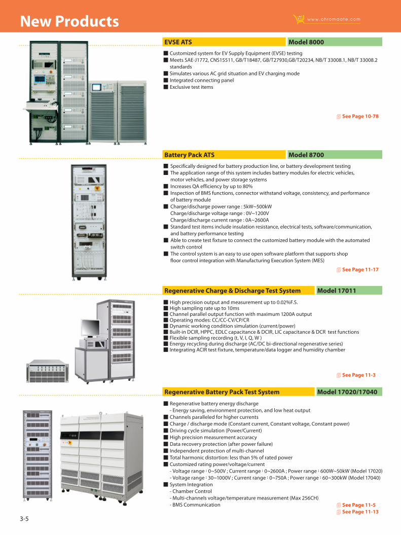
High precision output and measurement up to 0.02%F.S. High sampling rate up to 10ms Channel parallel output function with maximum 1200A output Operating modes: CC/CC-CV/CP/CR Dynamic working condition simulation (current/power) Built-in DCIR, HPPC, EDLC capacitance & DCIR, LIC capacitance & DCR test functions Flexible sampling recording (t, V, I, Q, W ) Energy recycling during discharge (AC/DC bi-directional regenerative series) Integrating ACIR test fixture, temperature/data logger and humidity chamber
Regenerative Charge & Discharge Test System Model 17011
4 See Page 11-3
Regenerative battery energy discharge - Energy saving, environment protection, and low heat output Channels paralleled for higher currents Charge / discharge mode (Constant current, Constant voltage, Constant power) Driving cycle simulation (Power/Current) High precision measurement accuracy Data recovery protection (after power failure) Independent protection of multi-channel Total harmonic distortion: less than 5% of rated power Customized rating power/voltage/current - Voltage range:0~500V ; Current range:0~2600A ; Power range:600W~50kW (Model 17020) - Voltage range:30~1000V ; Current range:0~750A ; Power range:60~300kW (Model 17040) System Integration - Chamber Control - Multi-channels voltage/temperature measurement (Max 256CH) - BMS Communication
Regenerative Battery Pack Test System Model 17020/17040
4 See Page 11-54 See Page 11-13
Customized system for EV Supply Equipment (EVSE) testing Meets SAE-J1772, CNS15511, GB/T18487, GB/T27930,GB/T20234, NB/T 33008.1, NB/T 33008.2 standards Simulates various AC grid situation and EV charging mode Integrated connecting panel Exclusive test items
EVSE ATS Model 8000
4 See Page 10-78
Specifically designed for battery production line, or battery development testing The application range of this system includes battery modules for electric vehicles, motor vehicles, and power storage systems Increases QA efficiency by up to 80% Inspection of BMS functions, connector withstand voltage, consistency, and performance of battery module Charge/discharge power range : 5kW~500kW Charge/discharge voltage range : 0V~1200V Charge/discharge current range : 0A~2600A Standard test items include insulation resistance, electrical tests, software/communication, and battery performance testing Able to create test fixture to connect the customized battery module with the automated switch control The control system is an easy to use open software platform that supports shop floor control integration with Manufacturing Execution System (MES)
Battery Pack ATS Model 8700
4 See Page 11-17
3-6
New Products
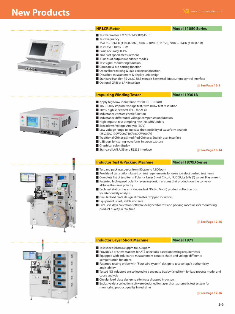
Test Parameter: L/C/R/Z/Y/DCR/Q/D/ θ Test Frequency : 75kHz ~ 30MHz (11050-30M), 1kHz ~ 10MHz (11050), 60Hz ~ 5MHz (11050-5M) Test Level: 10mV ~ 5V Basic Accuracy: 0.1% 7ms fast speed measurement 3 kinds of output impedance modes Test signal monitoring function Compare & bin-sorting function Open/short zeroing & load correction function Detached measurement & display unit design Standard Handler, RS-232C, USB storage & external bias current control interface Optional GPIB or LAN interface
HF LCR Meter Model 11050 Series
Inductor Layer Short Machine Model 1871
4 See Page 12-3
4 See Page 12-26
Test speeds from 600ppm to1,500ppm Provides 2 or 5 test stations for ATS selections based on testing requirements Equipped with inductance measurement contact check and voltage difference compensation functions Patented testing probe with "Four wire system" design to test voltage's authenticity and stability Tested NG inductors are collected to a separate box by failed item for bad process model and cause analysis Circular load plate design to eliminate dropped inductors Exclusive data collection software designed for layer short automatic test system for monitoring product quality in real time
Inductor Test & Packing Machine Model 1870D Series
Test and packing speeds from 80ppm to 1,800ppm Provides 4 test stations based on test requirements for users to select desired test items Complete list of test items: Polarity, Layer Short Circuit, IR, DCR, Ls & Rs (Q value), Bias current Patented high-speed polarity reversing design ensures that products on the conveyor all have the same polarity Each test station has an independent NG (No Good) product collection box for later quality analysis Circular load plate design eliminates dropped inductors Equipment is fast, stable and safe Exclusive data collection software designed for test and packing machines for monitoring product quality in real time
4 See Page 12-25
Impulsing Winding Tester Model 19301A
Apply high/low inductance test (0.1uH~100uH) 10V~1000V impulse voltage test, with 0.06V test resolution 20mS high speed test (P1.0 for ACQ) Inductance contact check function Inductance differential voltage compensation function High impulse test sampling rate (200MHz),10bits Breakdown Voltage Analysis (BDV) Low voltage range to increase the sensibility of waveform analysis (25V/50V/100V/200V/400V/800V/1000V) Traditional Chinese/Simplified Chinese/ English user interface USB port for storing waveform & screen capture Graphical color display Standard LAN, USB and RS232 interface 4 See Page 13-14
3-7
New Products
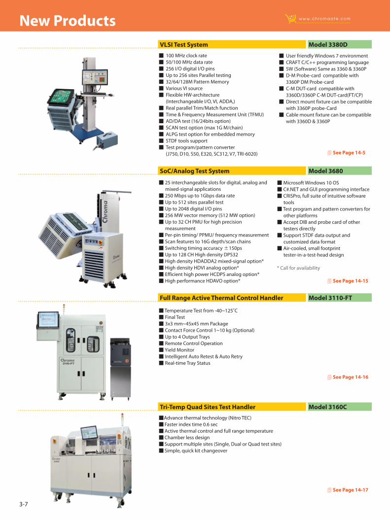
Advance thermal technology (Nitro TEC) Faster index time 0.6 sec Active thermal control and full range temperature Chamber less design Support multiple sites (Single, Dual or Quad test sites) Simple, quick kit changeover
Tri-Temp Quad Sites Test Handler Model 3160C
4 See Page 14-17
Temperature Test from -40~125˚C Final Test 3x3 mm~45x45 mm Package Contact Force Control 1~10 kg (Optional) Up to 4 Output Trays Remote Control Operation Yield Monitor Intelligent Auto Retest & Auto Retry Real-time Tray Status
Full Range Active Thermal Control Handler Model 3110-FT
4 See Page 14-16
25 interchangeable slots for digital, analog and mixed-signal applications 250 Mbps up to 1Gbps data rate Up to 512 sites parallel test Up to 2048 digital I/O pins 256 MW vector memory (512 MW option) Up to 32 CH PMU for high precision measurement Per-pin timing/ PPMU/ frequency measurement Scan features to 16G depth/scan chains Switching timing accuracy ±150ps Up to 128 CH High density DPS32 High density HDADDA2 mixed-signal option* High density HDVI analog option* Efficient high power HCDPS analog option* High performance HDAVO option*
100 MHz clock rate 50/100 MHz data rate 256 I/O digital I/O pins Up to 256 sites Parallel testing 32/64/128M Pattern Memory Various VI source Flexible HW-architecture (Interchangeable I/O, VI, ADDA,) Real parallel Trim/Match function Time & Frequency Measurement Unit (TFMU) AD/DA test (16/24bits option) SCAN test option (max 1G M/chain) ALPG test option for embedded memory STDF tools support Test program/pattern converter (J750, D10, S50, E320, SC312, V7, TRI-6020)
Microsoft Windows 10 OS C#.NET and GUI programming interface CRISPro, full suite of intuitive software tools Test program and pattern converters for other platforms Accept DIB and probe card of other testers directly Support STDF data output and customized data format Air-cooled, small footprint tester-in-a-test-head design
* Call for availability
User friendly Windows 7 environment CRAFT C/C++ programming language SW (Software) Same as 3360 & 3360P D-M Probe-card compatible with 3360P DM Probe-card C-M DUT-card compatible with 3360D/3360P C-M DUT-card(FT/CP) Direct mount fixture can be compatible with 3360P probe-Card Cable mount fixture can be compatible with 3360D & 3360P
SoC/Analog Test System Model 3680
VLSI Test System Model 3380D
4 See Page 14-5
4 See Page 14-15
3-8
New Products
PXIe Digital IO Card Model 33010
Device Power Supply Model 52310e Series
Manufacturing Execution System Model Sajet MES Series
4 See Page 14-3
4 See Page 15-6
4 See Page 17-1
4 See Page 18-1
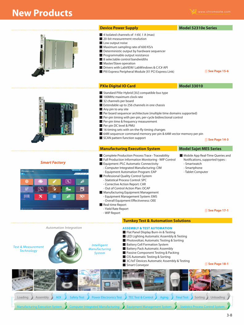
Standard PXIe-Hybrid [3U] compatible bus type 100MHz maximum clock rate 32 channels per board Extendable up to 256 channels in one chassis Any pin to any site Per board sequencer architecture (multiple time domains supported) Per-pin timing with per-pin, per-cycle bidirectional control Per-pin time & frequency measurement Per-pin DC level & PMU 16 timing sets with on-the-fly timing changes 64M sequencer command memory per pin & 64M vector memory per pin SCAN pattern function support
4 Isolated channels of ±6V, 1 A (max) 20-bit measurement resolution Low output noise Maximum sampling rate of 600 KS/s Deterministic output by hardware sequencer Programmable output resistance 8 selectable control bandwidths Master/Slave operation Drivers with LabVIEW/ LabWindows & C/C# API PXI Express Peripheral Module (X1 PCI Express Link)
Complete Production Process Trace - Traceability Full Production Information Monitoring - WIP Control Equipment /PLC Automatic Connectivity - Computer Integrated Manufacturing: CIM - Equipment Automation Program: EAP Professional Quality Control System - Statistical Process Control: SPC - Corrective Action Report: CAR - Out of Control Action Plan: OCAP Manufacturing Equipment Management - Equipment Management System: EMS - Overall Equipment Effectiveness: OEE Real-time Report - Yield Rate Report - WIP Report
ASSEMBLY & TEST AUTOMATION Flat Panel Display Burn-in & Testing LED Lighting Automatic Assembly & Testing Photovoltaic Automatic Testing & Sorting Battery Cell Formation System Battery Pack Automatic Assembly Passive Component Testing & Packing CIS Automatic Testing & Sorting 3C/IoT Devices Automatic Assembly & Testing Smart Conveyor
Turnkey Test & Automation Solutions
Test & MeasurementTechnology
IntelligentManufacturing
System
Automation Integration
Loading Assembly AgingPower Electronics Test SortingAOI Safety Test Final TestTEC Test & Control Unloading
Manufacturing Execution System Equipment Management System Statistics Process Control SystemComputer Integrated Manufacturing
Smart Factory
Mobile App Real-Time Queries and Notifications, supported types :
- Smartwatch - Smartphone - Tablet Computer
Selection Guides 4-1
Video Pattern Generator (VPG) 4-3
HDMI Distributor 4-18
MHL Module 4-19
SDI Module 4-20
Pattern Analyzer 4-21
Display Color Analyzer 4-22
Front Projector ATS 4-24
Video & Color Test Solution
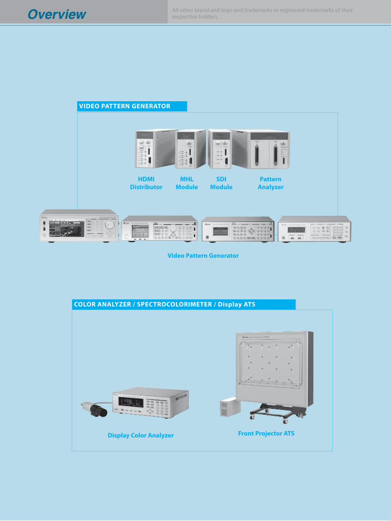
Overview
HDMIDistributor
MHLModule
Display Color Analyzer
Video Pattern Generator
VIDEO PATTERN GENERATOR
COLOR ANALYZER / SPECTROCOLORIMETER / Display ATS
SDIModule
Front Projector ATS
Overview All other brand and logo and trademarks or registered trademarks of theirrespective holders.
PatternAnalyzer
Selection Guides
All specifications are subject to change without notice. All specifications are subject to change without notice.4-1
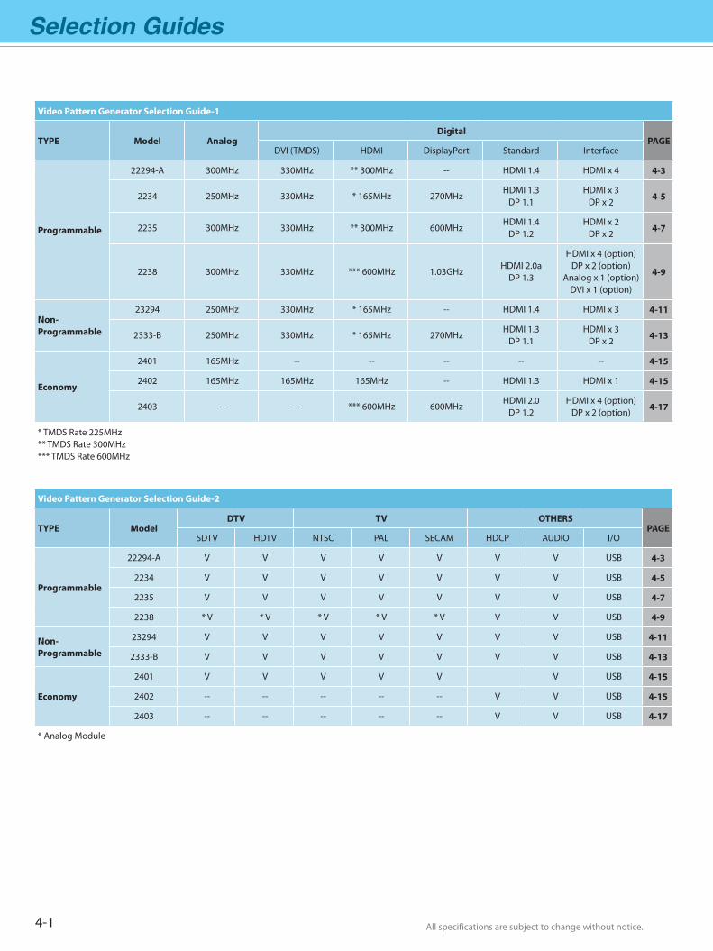
Video Pattern Generator Selection Guide-1
TYPE Model AnalogDigital
PAGEDVI (TMDS) HDMI DisplayPort Standard Interface
Programmable
22294-A 300MHz 330MHz ** 300MHz -- HDMI 1.4 HDMI x 4 4-3
2234 250MHz 330MHz * 165MHz 270MHzHDMI 1.3
DP 1.1HDMI x 3
DP x 2 4-5
2235 300MHz 330MHz ** 300MHz 600MHzHDMI 1.4
DP 1.2HDMI x 2
DP x 2 4-7
2238 300MHz 330MHz *** 600MHz 1.03GHzHDMI 2.0a
DP 1.3
HDMI x 4 (option)DP x 2 (option)
Analog x 1 (option)DVI x 1 (option)
4-9
Non-Programmable
23294 250MHz 330MHz * 165MHz -- HDMI 1.4 HDMI x 3 4-11
2333-B 250MHz 330MHz * 165MHz 270MHzHDMI 1.3
DP 1.1HDMI x 3
DP x 2 4-13
Economy
2401 165MHz -- -- -- -- -- 4-15
2402 165MHz 165MHz 165MHz -- HDMI 1.3 HDMI x 1 4-15
2403 -- -- *** 600MHz 600MHzHDMI 2.0
DP 1.2HDMI x 4 (option)
DP x 2 (option) 4-17
* TMDS Rate 225MHz** TMDS Rate 300MHz*** TMDS Rate 600MHz
Video Pattern Generator Selection Guide-2
TYPE ModelDTV TV OTHERS
PAGESDTV HDTV NTSC PAL SECAM HDCP AUDIO I/O
Programmable
22294-A V V V V V V V USB 4-3
2234 V V V V V V V USB 4-5
2235 V V V V V V V USB 4-7
2238 * V * V * V * V * V V V USB 4-9
Non-Programmable
23294 V V V V V V V USB 4-11
2333-B V V V V V V V USB 4-13
Economy
2401 V V V V V V USB 4-15
2402 -- -- -- -- -- V V USB 4-15
2403 -- -- -- -- -- V V USB 4-17
* Analog Module
All specifications are subject to change without notice. All specifications are subject to change without notice. 4-2
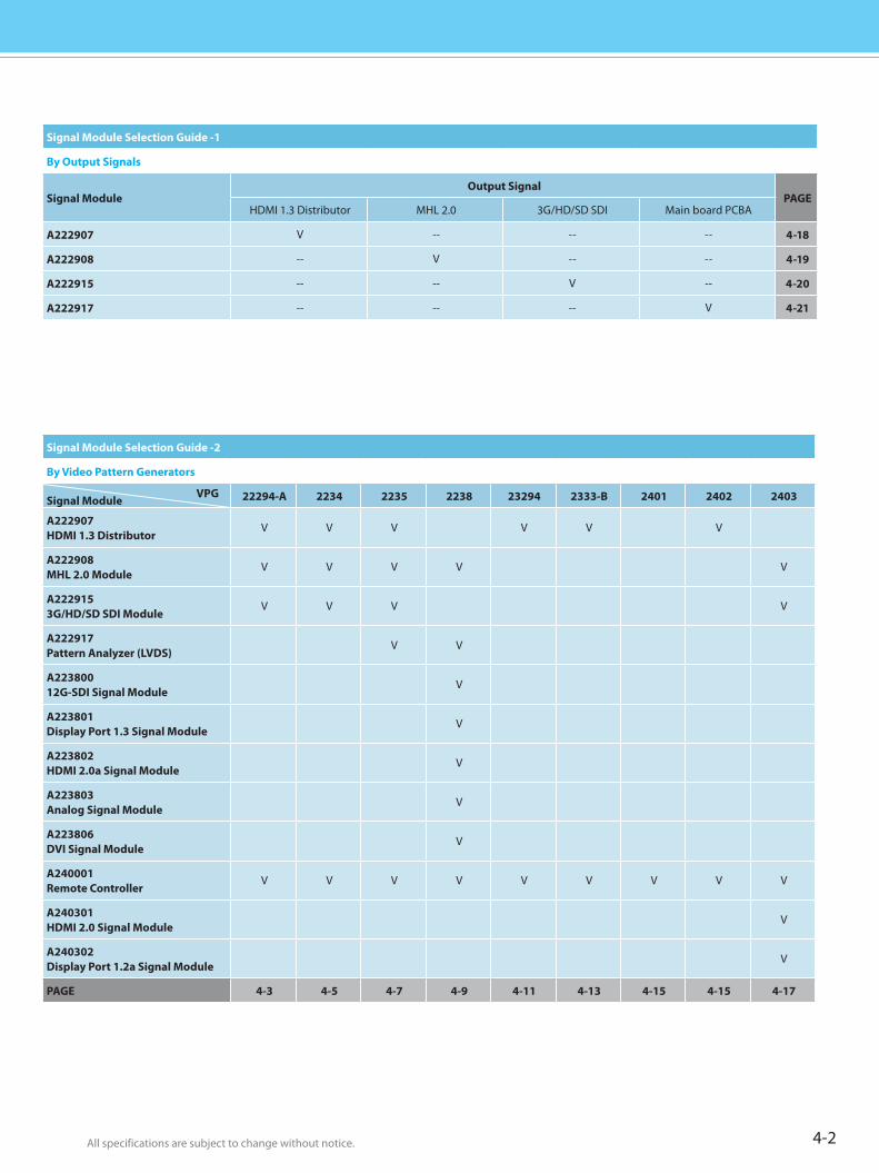
Signal Module Selection Guide -1
By Output Signals
Signal ModuleOutput Signal
PAGEHDMI 1.3 Distributor MHL 2.0 3G/HD/SD SDI Main board PCBA
A222907 V -- -- -- 4-18
A222908 -- V -- -- 4-19
A222915 -- -- V -- 4-20
A222917 -- -- -- V 4-21
Signal Module Selection Guide -2
By Video Pattern Generators
Signal Module VPG 22294-A 2234 2235 2238 23294 2333-B 2401 2402 2403
A222907HDMI 1.3 Distributor
V V V V V V
A222908MHL 2.0 Module
V V V V V
A2229153G/HD/SD SDI Module
V V V V
A222917Pattern Analyzer (LVDS)
V V
A22380012G-SDI Signal Module
V
A223801Display Port 1.3 Signal Module
V
A223802HDMI 2.0a Signal Module
V
A223803Analog Signal Module
V
A223806DVI Signal Module
V
A240001Remote Controller
V V V V V V V V V
A240301HDMI 2.0 Signal Module
V
A240302Display Port 1.2a Signal Module
V
PAGE 4-3 4-5 4-7 4-9 4-11 4-13 4-15 4-15 4-17
4-3 All specifications are subject to change without notice. All specifications are subject to change without notice.
Video Pattern Generator Model 22294-A
Analog 300 MHzDVI (TMDS) 330 MHzHDMI V1.4a 300 MHz(TMDS Rate 300 MHz)Multi-port HDMIx43D Output
KEY FEATURES Fully Comparable with HDMI 1.4 Standard - 3D Format Output - Audio Return Channel - Ethernet Channel - 4Kx2K / 1080P 120Hz - sYCC601 / Adobe RGB / Adobe sYCC601 - CEC / Deep Color / Lip-Sync / xvYCC Multi ports output test application - HDMI port output x 4 - SCART port x 2 (output x1/input x1) 330MHz digital (DVI) frequency Support Dual HDCP in DVI test application HDCP supports Auto / Manual Mode Ethernet Browser on Screen HDCP ON / OFF IN DVI & HDMI Interface S-Video / CVBS / SCART / RGB / Y.Pb.Pr / Y.Cb.Cr / Y,R-Y,B-Y / D-terminal NTSC / PAL / SECAM signals EDID Read/ Write/Compare/Analysis Optical / coaxial audio input (SPDIF) Support pattern dynamic scrolling Built-in China high definition standard HD patterns HDMI/DVI Hot-Plug function Support Gamma calibration ESD protection circuit Front USB & control interface PIP & OSD function
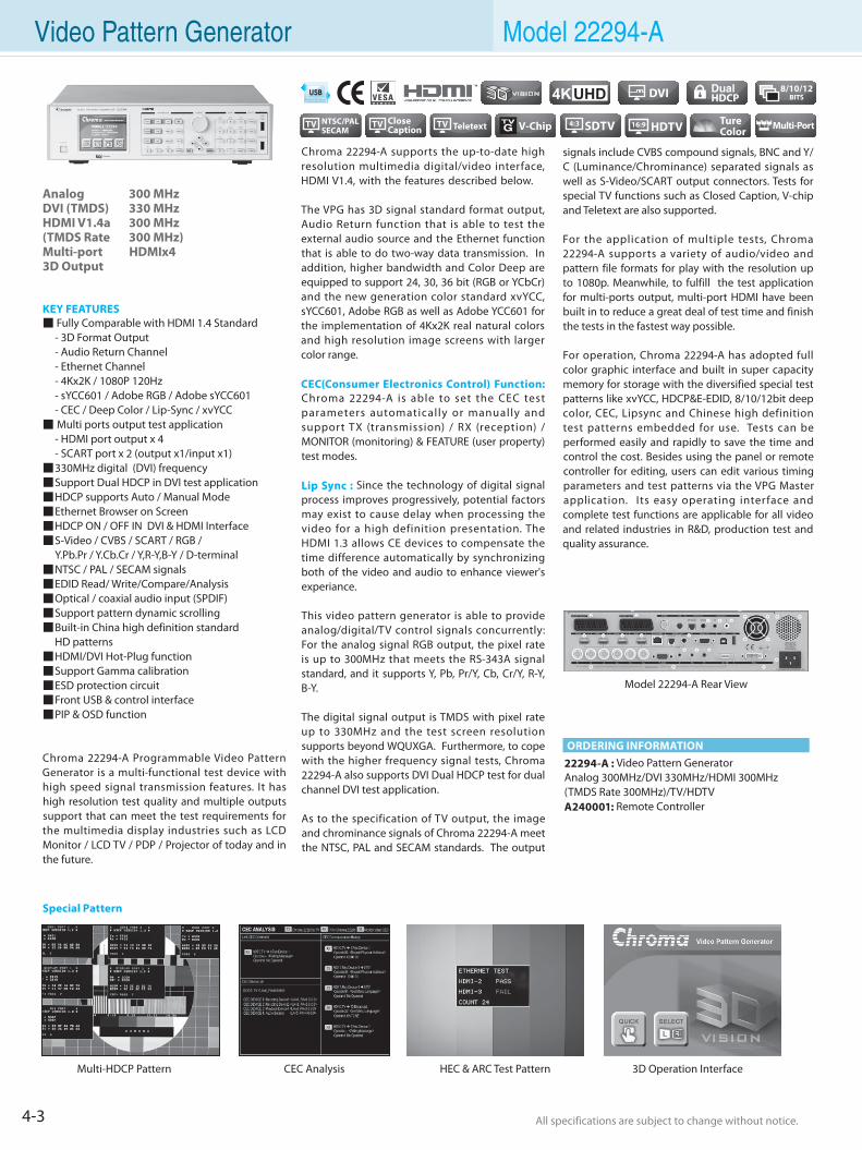
Chroma 22294-A Programmable Video Pattern Generator is a multi-functional test device with high speed signal transmission features. It has high resolution test quality and multiple outputs support that can meet the test requirements for the multimedia display industries such as LCD Monitor / LCD TV / PDP / Projector of today and in the future.
Chroma 22294-A supports the up-to-date high resolution multimedia digital/video interface, HDMI V1.4, with the features described below. The VPG has 3D signal standard format output, Audio Return function that is able to test the external audio source and the Ethernet function that is able to do two-way data transmission. In addition, higher bandwidth and Color Deep are equipped to support 24, 30, 36 bit (RGB or YCbCr) and the new generation color standard xvYCC, sYCC601, Adobe RGB as well as Adobe YCC601 for the implementation of 4Kx2K real natural colors and high resolution image screens with larger color range.
CEC(Consumer Electronics Control) Function: Chroma 22294-A is able to set the CEC test parameters automatically or manually and support TX (transmission) / RX (reception) / MONITOR (monitoring) & FEATURE (user property) test modes.
Lip Sync : Since the technology of digital signal process improves progressively, potential factors may exist to cause delay when processing the video for a high definition presentation. The HDMI 1.3 allows CE devices to compensate the time difference automatically by synchronizing both of the video and audio to enhance viewer's experiance.
This video pattern generator is able to provide analog/digital/TV control signals concurrently: For the analog signal RGB output, the pixel rate is up to 300MHz that meets the RS-343A signal standard, and it supports Y, Pb, Pr/Y, Cb, Cr/Y, R-Y, B-Y.
The digital signal output is TMDS with pixel rate up to 330MHz and the test screen resolution supports beyond WQUXGA. Furthermore, to cope with the higher frequency signal tests, Chroma 22294-A also supports DVI Dual HDCP test for dual channel DVI test application.
As to the specification of TV output, the image and chrominance signals of Chroma 22294-A meet the NTSC, PAL and SECAM standards. The output
22294-A : Video Pattern GeneratorAnalog 300MHz/DVI 330MHz/HDMI 300MHz (TMDS Rate 300MHz)/TV/HDTVA240001: Remote Controller
signals include CVBS compound signals, BNC and Y/C (Luminance/Chrominance) separated signals as well as S-Video/SCART output connectors. Tests for special TV functions such as Closed Caption, V-chip and Teletext are also supported.
For the application of multiple tests, Chroma 22294-A supports a variety of audio/video and pattern file formats for play with the resolution up to 1080p. Meanwhile, to fulfill the test application for multi-ports output, multi-port HDMI have been built in to reduce a great deal of test time and finish the tests in the fastest way possible.
For operation, Chroma 22294-A has adopted full color graphic interface and built in super capacity memory for storage with the diversified special test patterns like xvYCC, HDCP&E-EDID, 8/10/12bit deep color, CEC, Lipsync and Chinese high definition test patterns embedded for use. Tests can be performed easily and rapidly to save the time and control the cost. Besides using the panel or remote controller for editing, users can edit various timing parameters and test patterns via the VPG Master application. Its easy operating interface and complete test functions are applicable for all video and related industries in R&D, production test and quality assurance.
ORDERING INFORMATION
CEC AnalysisMulti-HDCP Pattern 3D Operation InterfaceHEC & ARC Test Pattern
Special Pattern
Model 22294-A Rear View
4KUHD
TV NTSC/PALSECAM
4-4All specifications are subject to change without notice. All specifications are subject to change without notice.
Flat PanelD
isplayPow
er Electronics
Electrical Safety
General
PurposePassive
Component
Semiconductor/
ICBattery Test & Autom
ationAutom
atedO
ptical Inspection Photovoltaic Test
& Automation
PXI Test &
Measurem
ent Video & Color
LED/
LightingO
ptical D
evicesIntelligent
Manufacturing System
Turnkey Test & Autom
ation Video Pattern Generator Model 22294-A
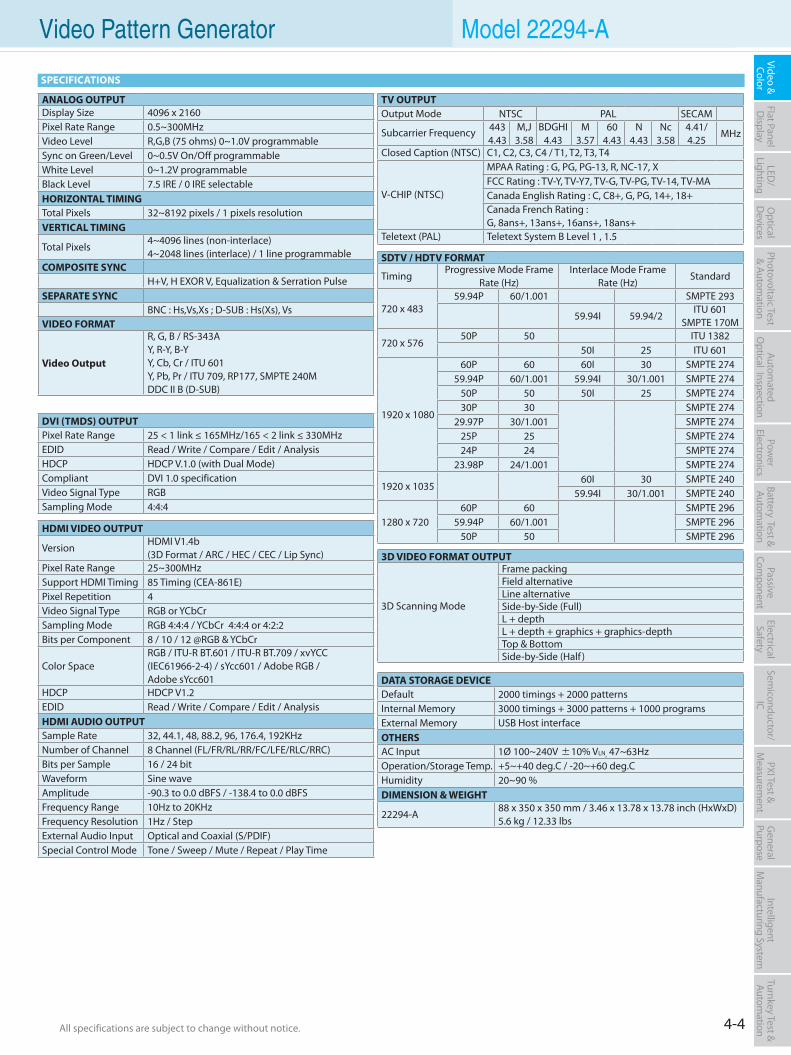
SDTV / HDTV FORMAT
Timing Progressive Mode Frame
Rate (Hz) Interlace Mode Frame
Rate (Hz)Standard
720 x 483 59.94P 60/1.001 SMPTE 293
59.94I 59.94/2 ITU 601
SMPTE 170M
720 x 576 50P 50 ITU 1382
50I 25 ITU 601
1920 x 1080
60P 60 60I 30 SMPTE 27459.94P 60/1.001 59.94I 30/1.001 SMPTE 274
50P 50 50I 25 SMPTE 27430P 30 SMPTE 274
29.97P 30/1.001 SMPTE 27425P 25 SMPTE 27424P 24 SMPTE 274
23.98P 24/1.001 SMPTE 274
1920 x 1035 60I 30 SMPTE 240
59.94I 30/1.001 SMPTE 240
1280 x 720 60P 60 SMPTE 296
59.94P 60/1.001 SMPTE 29650P 50 SMPTE 296
TV OUTPUTOutput Mode NTSC PAL SECAM
Subcarrier Frequency 4434.43
M,J3.58
BDGHI4.43
M3.57
604.43
N4.43
Nc3.58
4.41/4.25
MHz
Closed Caption (NTSC) C1, C2, C3, C4 / T1, T2, T3, T4
V-CHIP (NTSC)
MPAA Rating : G, PG, PG-13, R, NC-17, XFCC Rating : TV-Y, TV-Y7, TV-G, TV-PG, TV-14, TV-MACanada English Rating : C, C8+, G, PG, 14+, 18+Canada French Rating : G, 8ans+, 13ans+, 16ans+, 18ans+
Teletext (PAL) Teletext System B Level 1 , 1.5
ANALOG OUTPUTDisplay Size 4096 x 2160Pixel Rate Range 0.5~300MHzVideo Level R,G,B (75 ohms) 0~1.0V programmableSync on Green/Level 0~0.5V On/Off programmableWhite Level 0~1.2V programmableBlack Level 7.5 IRE / 0 IRE selectableHORIZONTAL TIMINGTotal Pixels 32~8192 pixels / 1 pixels resolutionVERTICAL TIMING
Total Pixels 4~4096 lines (non-interlace)4~2048 lines (interlace) / 1 line programmable
COMPOSITE SYNC H+V, H EXOR V, Equalization & Serration Pulse
SEPARATE SYNC BNC : Hs,Vs,Xs ; D-SUB : Hs(Xs), Vs
VIDEO FORMAT
Video Output
R, G, B / RS-343AY, R-Y, B-YY, Cb, Cr / ITU 601Y, Pb, Pr / ITU 709, RP177, SMPTE 240MDDC II B (D-SUB)
DVI (TMDS) OUTPUTPixel Rate Range 25 < 1 link ≤ 165MHz/165 < 2 link ≤ 330MHz EDID Read / Write / Compare / Edit / AnalysisHDCP HDCP V.1.0 (with Dual Mode)Compliant DVI 1.0 specificationVideo Signal Type RGBSampling Mode 4:4:4
DATA STORAGE DEVICEDefault 2000 timings + 2000 patternsInternal Memory 3000 timings + 3000 patterns + 1000 programsExternal Memory USB Host interfaceOTHERSAC Input 1Ø 100~240V ±10% VLN, 47~63HzOperation/Storage Temp. +5~+40 deg.C / -20~+60 deg.CHumidity 20~90 %DIMENSION & WEIGHT
22294-A88 x 350 x 350 mm / 3.46 x 13.78 x 13.78 inch (HxWxD)5.6 kg / 12.33 lbs
HDMI VIDEO OUTPUT
Version HDMI V1.4b (3D Format / ARC / HEC / CEC / Lip Sync)
Pixel Rate Range 25~300MHzSupport HDMI Timing 85 Timing (CEA-861E)Pixel Repetition 4Video Signal Type RGB or YCbCrSampling Mode RGB 4:4:4 / YCbCr 4:4:4 or 4:2:2Bits per Component 8 / 10 / 12 @RGB & YCbCr
Color Space RGB / ITU-R BT.601 / ITU-R BT.709 / xvYCC (IEC61966-2-4) / sYcc601 / Adobe RGB / Adobe sYcc601
HDCP HDCP V1.2EDID Read / Write / Compare / Edit / AnalysisHDMI AUDIO OUTPUTSample Rate 32, 44.1, 48, 88.2, 96, 176.4, 192KHzNumber of Channel 8 Channel (FL/FR/RL/RR/FC/LFE/RLC/RRC)Bits per Sample 16 / 24 bitWaveform Sine waveAmplitude -90.3 to 0.0 dBFS / -138.4 to 0.0 dBFSFrequency Range 10Hz to 20KHzFrequency Resolution 1Hz / StepExternal Audio Input Optical and Coaxial (S/PDIF)Special Control Mode Tone / Sweep / Mute / Repeat / Play Time
SPECIFICATIONS
3D VIDEO FORMAT OUTPUT
3D Scanning Mode
Frame packing Field alternativeLine alternativeSide-by-Side (Full)L + depthL + depth + graphics + graphics-depthTop & BottomSide-by-Side (Half )
4-5 All specifications are subject to change without notice. All specifications are subject to change without notice.
Video Pattern Generator Model 2234
Analog 250 MHzDVI (TMDS) 330 MHzHDMI V1.3C 165 MHz(TMDS Rate 225 MHz) DisplayPort V1.1a 270 MHzMulti-port (HDMIx3, DPx2)Multimedia Audio/Video
KEY FEATURES Support multimedia audio / video play formats Support up to 1080p high definition resolution Multi ports independent output test application - HDMI port output x 3 - DisplayPort output x 2 - SCART port x 2 (output x 1 / input x 1) DisplayPort V1.1a pixel rate 270MHz DisplayPort supports HDCP V1.3 Support automatically & manually setting for DisplayPort function - 2 Link rate (1.62 / 2.7Gbps) selectable - 1, 2, 4 Video lane selectable - 0 / 3.5 / 6 / 9.5dB pre-emphasis selectable - 400 / 600 / 800 / 1200mV swing level selectable Support HDMI V1.3C (with 24, 30, 36bit color depth / xvYCC / CEC / Lip Sync) Support dual HDCP in DVI test application HDCP supports auto / manual mode HDMI and DisplayPort multiplexer function or switching for independent output HDCP ON/OFF in DVI, HDMI & DisplayPort interface Y, Pb, Pr / Y, Cb, Cr / Y, R-Y, B-Y output S-Video / CVBS / SCART / RGB / Color Component / D-terminal NTSC / PAL / SECAM signals EDID read / write / compare Optical / coaxial audio input (SPDIF) Scrolling pattern support Built-in China HD standard test patterns HDMI / DVI hot plug function
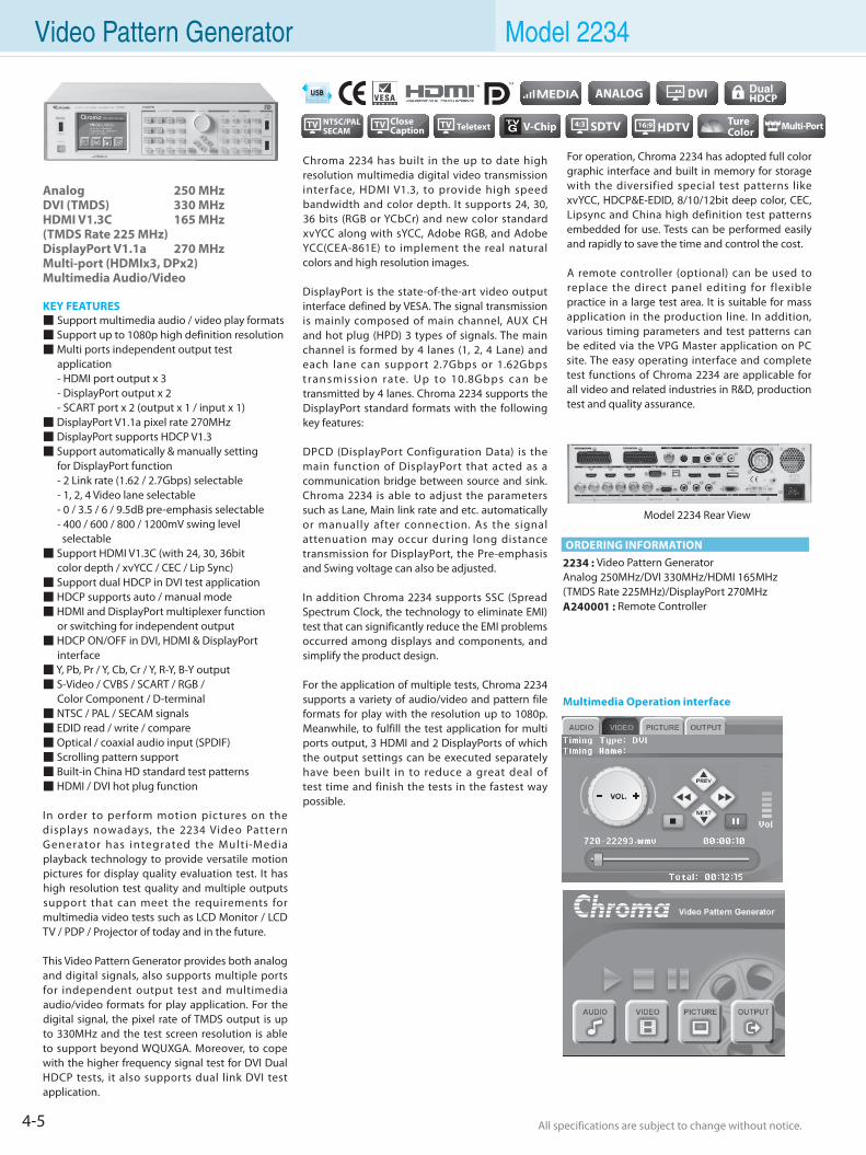
In order to perform motion pictures on the displays nowadays, the 2234 Video Pattern Generator has integrated the Mult i-Media playback technology to provide versatile motion pictures for display quality evaluation test. It has high resolution test quality and multiple outputs support that can meet the requirements for multimedia video tests such as LCD Monitor / LCD TV / PDP / Projector of today and in the future.
This Video Pattern Generator provides both analog and digital signals, also supports multiple ports for independent output test and multimedia audio/video formats for play application. For the digital signal, the pixel rate of TMDS output is up to 330MHz and the test screen resolution is able to support beyond WQUXGA. Moreover, to cope with the higher frequency signal test for DVI Dual HDCP tests, it also supports dual link DVI test application.
Chroma 2234 has built in the up to date high resolution multimedia digital video transmission interface, HDMI V1.3, to provide high speed bandwidth and color depth. It supports 24, 30, 36 bits (RGB or YCbCr) and new color standard xvYCC along with sYCC, Adobe RGB, and Adobe YCC(CEA-861E) to implement the real natural colors and high resolution images.
DisplayPort is the state-of-the-art video output interface defined by VESA. The signal transmission is mainly composed of main channel, AUX CH and hot plug (HPD) 3 types of signals. The main channel is formed by 4 lanes (1, 2, 4 Lane) and each lane can support 2.7Gbps or 1.62Gbps t ran smiss ion rate. Up to 10.8Gbps can be transmitted by 4 lanes. Chroma 2234 supports the DisplayPort standard formats with the following key features:
DPCD (DisplayPort Configuration Data) is the main function of DisplayPort that acted as a communication bridge between source and sink. Chroma 2234 is able to adjust the parameters such as Lane, Main link rate and etc. automatically or manually after connection. As the signal attenuation may occur during long distance transmission for DisplayPort, the Pre-emphasis and Swing voltage can also be adjusted.
In addition Chroma 2234 supports SSC (Spread Spectrum Clock, the technology to eliminate EMI) test that can significantly reduce the EMI problems occurred among displays and components, and simplify the product design.
For the application of multiple tests, Chroma 2234 supports a variety of audio/video and pattern file formats for play with the resolution up to 1080p. Meanwhile, to fulfill the test application for multi ports output, 3 HDMI and 2 DisplayPorts of which the output settings can be executed separately have been built in to reduce a great deal of test time and finish the tests in the fastest way possible.
For operation, Chroma 2234 has adopted full color graphic interface and built in memory for storage with the diversified special test patterns like xvYCC, HDCP&E-EDID, 8/10/12bit deep color, CEC, Lipsync and China high definition test patterns embedded for use. Tests can be performed easily and rapidly to save the time and control the cost.
A remote controller (optional) can be used to replace the direct panel editing for flexible practice in a large test area. It is suitable for mass application in the production line. In addition, various timing parameters and test patterns can be edited via the VPG Master application on PC site. The easy operating interface and complete test functions of Chroma 2234 are applicable for all video and related industries in R&D, production test and quality assurance.
2234 : Video Pattern GeneratorAnalog 250MHz/DVI 330MHz/HDMI 165MHz (TMDS Rate 225MHz)/DisplayPort 270MHzA240001 : Remote Controller
Model 2234 Rear View
ORDERING INFORMATION
TV NTSC/PALSECAM
Multimedia Operation interface
4-6All specifications are subject to change without notice. All specifications are subject to change without notice.
Flat PanelD
isplayPow
er Electronics
Electrical Safety
General
PurposePassive
Component
Semiconductor/
ICBattery Test & Autom
ationAutom
atedO
ptical Inspection Photovoltaic Test
& Automation
PXI Test &
Measurem
ent Video & Color
LED/
LightingO
ptical D
evicesIntelligent
Manufacturing System
Turnkey Test & Autom
ation Video Pattern Generator Model 2234
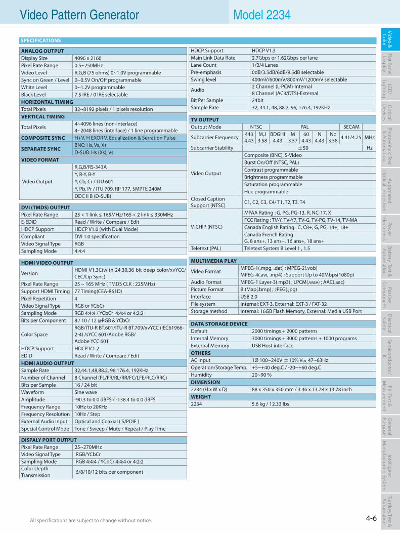
HDCP Support HDCP V1.3Main Link Data Rate 2.7Gbps or 1.62Gbps per laneLane Count 1/2/4 LanesPre-emphasis 0dB/3.5dB/6dB/9.5dB selectableSwing level 400mV/600mV/800mV/1200mV selectable
Audio2 Channel (L-PCM)-Internal8 Channel (AC3/DTS)-External
Bit Per Sample 24bitSample Rate 32, 44.1, 48, 88.2, 96, 176.4, 192KHz
DISPALY PORT OUTPUTPixel Rate Range 25~270MHzVideo Signal Type RGB/YCbCrSampling Mode RGB 4:4:4 / YCbCr 4:4:4 or 4:2:2Color Depth Transmission
6/8/10/12 bits per component
ANALOG OUTPUTDisplay Size 4096 x 2160Pixel Rate Range 0.5~250MHzVideo Level R,G,B (75 ohms) 0~1.0V programmableSync on Green / Level 0~0.5V On/Off programmableWhite Level 0~1.2V programmableBlack Level 7.5 IRE / 0 IRE selectableHORIZONTAL TIMINGTotal Pixels 32~8192 pixels / 1 pixels resolutionVERTICAL TIMING
Total Pixels 4~4096 lines (non-interlace)4~2048 lines (interlace) / 1 line programmable
COMPOSITE SYNC H+V, H EXOR V, Equalization & Serration Pulse
SEPARATE SYNC BNC: Hs, Vs, XsD-SUB: Hs (Xs), Vs
VIDEO FORMAT
Video Output
R,G,B/RS-343AY, R-Y, B-YY, Cb, Cr / ITU 601Y, Pb, Pr / ITU 709, RP 177, SMPTE 240MDDC II B (D-SUB)
DVI (TMDS) OUTPUTPixel Rate Range 25 < 1 link ≤ 165MHz/165 < 2 link ≤ 330MHz E-EDID Read / Write / Compare / EditHDCP Support HDCP V1.0 (with Dual Mode)Compliant DVI 1.0 specificationVideo Signal Type RGBSampling Mode 4:4:4
DATA STORAGE DEVICEDefault 2000 timings + 2000 patternsInternal Memory 3000 timings + 3000 patterns + 1000 programsExternal Memory USB Host interfaceOTHERSAC Input 1Ø 100~240V ±10% VLN, 47~63HzOperation/Storage Temp. +5~+40 deg.C / -20~+60 deg.CHumidity 20~90 %DIMENSION2234 (H x W x D) 88 x 350 x 350 mm / 3.46 x 13.78 x 13.78 inchWEIGHT2234 5.6 kg / 12.33 lbs
TV OUTPUTOutput Mode NTSC PAL SECAM
Subcarrier Frequency 4434.43
M,J3.58
BDGHI4.43
M3.57
604.43
N4.43
Nc3.58 4.41/4.25 MHz
Subcarrier Stability ±50 Hz
Video Output
Composite (BNC), S-VideoBurst On/Off (NTSC, PAL)Contrast programmableBrightness programmableSaturation programmableHue programmable
Closed Caption Support (NTSC) C1, C2, C3, C4/ T1, T2, T3, T4
V-CHIP (NTSC)
MPAA Rating : G, PG, PG-13, R, NC-17, XFCC Rating : TV-Y, TV-Y7, TV-G, TV-PG, TV-14, TV-MACanada English Rating : C, C8+, G, PG, 14+, 18+Canada French Rating : G, 8 ans+, 13 ans+, 16 ans+, 18 ans+
Teletext (PAL) Teletext System B Level 1 , 1.5
HDMI VIDEO OUTPUT
Version HDMI V1.3C(with 24,30,36 bit deep color/xvYCC/CEC/Lip Sync)
Pixel Rate Range 25 ~ 165 MHz ( TMDS CLK : 225MHz)Support HDMI Timing 77 Timing(CEA-861D)Pixel Repetition 4Video Signal Type RGB or YCbCrSampling Mode RGB 4:4:4 / YCbCr 4:4:4 or 4:2:2Bits per Component 8 / 10 / 12 @RGB & YCbCr
Color Space RGB/ITU-R BT.601/ITU-R BT.709/xvYCC (IEC61966-2-4) /sYCC 601/Adobe RGB/Adobe YCC 601
HDCP Support HDCP V.1.2EDID Read / Write / Compare / EditHDMI AUDIO OUTPUTSample Rate 32,44.1,48,88.2, 96,176.4, 192KHzNumber of Channel 8 Channel (FL/FR/RL/RR/FC/LFE/RLC/RRC)Bits per Sample 16 / 24 bitWaveform Sine waveAmplitude -90.3 to 0.0 dBFS / -138.4 to 0.0 dBFSFrequency Range 10Hz to 20KHzFrequency Resolution 10Hz / StepExternal Audio Input Optical and Coaxial ( S/PDIF )Special Control Mode Tone / Sweep / Mute / Repeat / Play Time
MULTIMEDIA PLAY
Video FormatMPEG-1(.mpg, .dat) ; MPEG-2(.vob)MPEG-4(.avi, .mp4) ; Support Up to 40Mbps(1080p)
Audio Format MPEG-1 Layer-3(.mp3) ; LPCM(.wav) ; AAC(.aac)Picture Format BitMap(.bmp) ; JPEG(.jpg)Interface USB 2.0File system Internal: EXT-3, External: EXT-3 / FAT-32Storage method Internal: 16GB Flash Memory, External: Media USB Port
SPECIFICATIONS
4-7 All specifications are subject to change without notice. All specifications are subject to change without notice.
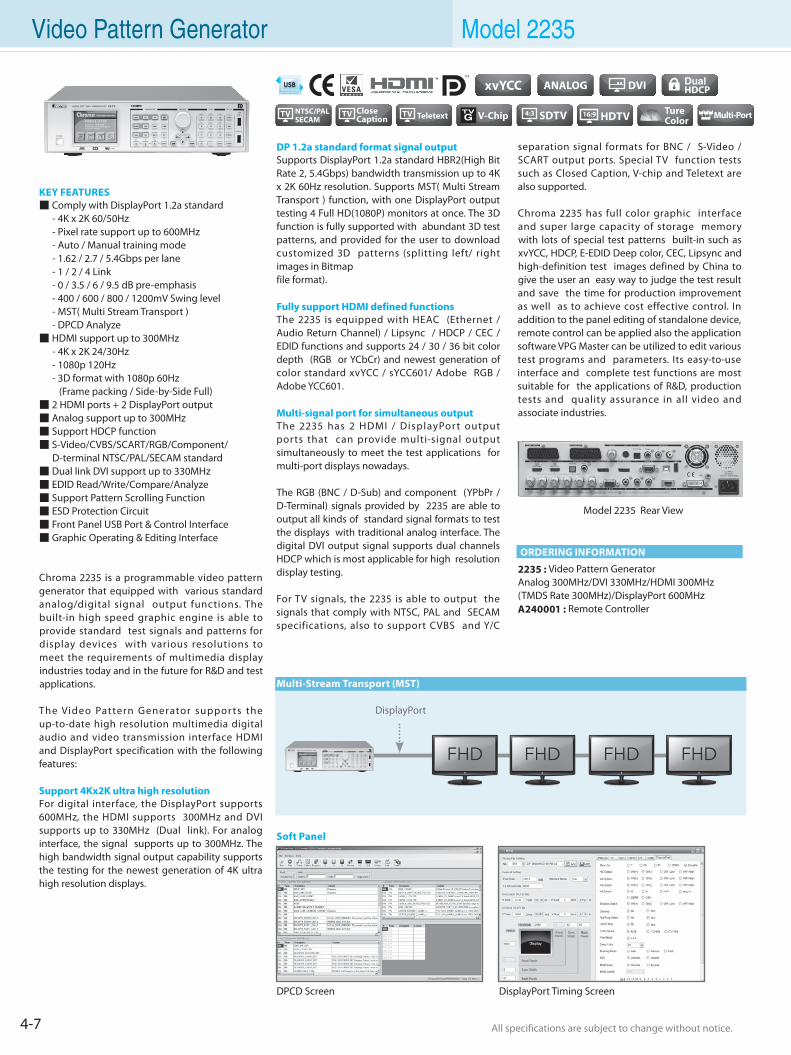
Video Pattern Generator Model 2235
KEY FEATURES Comply with DisplayPort 1.2a standard - 4K x 2K 60/50Hz - Pixel rate support up to 600MHz - Auto / Manual training mode - 1.62 / 2.7 / 5.4Gbps per lane - 1 / 2 / 4 Link - 0 / 3.5 / 6 / 9.5 dB pre-emphasis - 400 / 600 / 800 / 1200mV Swing level - MST( Multi Stream Transport ) - DPCD Analyze HDMI support up to 300MHz - 4K x 2K 24/30Hz - 1080p 120Hz - 3D format with 1080p 60Hz (Frame packing / Side-by-Side Full) 2 HDMI ports + 2 DisplayPort output Analog support up to 300MHz Support HDCP function S-Video/CVBS/SCART/RGB/Component/ D-terminal NTSC/PAL/SECAM standard Dual link DVI support up to 330MHz EDID Read/Write/Compare/Analyze Support Pattern Scrolling Function ESD Protection Circuit Front Panel USB Port & Control Interface Graphic Operating & Editing Interface
Chroma 2235 is a programmable video pattern generator that equipped with various standard analog/digital signal output functions. The built-in high speed graphic engine is able to provide standard test signals and patterns for display devices with various resolutions to meet the requirements of multimedia display industries today and in the future for R&D and test applications.
The Video Pattern Generator suppor ts the up-to-date high resolution multimedia digital audio and video transmission interface HDMI and DisplayPort specification with the following features: Support 4Kx2K ultra high resolutionFor digital interface, the DisplayPort supports 600MHz, the HDMI supports 300MHz and DVI supports up to 330MHz (Dual link). For analog interface, the signal supports up to 300MHz. The high bandwidth signal output capability supports the testing for the newest generation of 4K ultra high resolution displays.
DP 1.2a standard format signal outputSupports DisplayPort 1.2a standard HBR2(High Bit Rate 2, 5.4Gbps) bandwidth transmission up to 4K x 2K 60Hz resolution. Supports MST( Multi Stream Transport ) function, with one DisplayPort output testing 4 Full HD(1080P) monitors at once. The 3D function is fully supported with abundant 3D test patterns, and provided for the user to download customized 3D patterns (splitting left/ right images in Bitmap file format).
Fully support HDMI defined functionsThe 2235 is equipped with HEAC (Ethernet / Audio Return Channel) / Lipsync / HDCP / CEC / EDID functions and supports 24 / 30 / 36 bit color depth (RGB or YCbCr) and newest generation of color standard xvYCC / sYCC601/ Adobe RGB / Adobe YCC601.
Multi-signal port for simultaneous outputThe 2235 has 2 HDMI / DisplayPor t output ports that can provide multi-signal output simultaneously to meet the test applications for multi-port displays nowadays.
The RGB (BNC / D-Sub) and component (YPbPr / D-Terminal) signals provided by 2235 are able to output all kinds of standard signal formats to test the displays with traditional analog interface. The digital DVI output signal supports dual channels HDCP which is most applicable for high resolution display testing.
For TV signals, the 2235 is able to output the signals that comply with NTSC, PAL and SECAM specifications, also to support CVBS and Y/C
separation signal formats for BNC / S-Video / SCART output ports. Special TV function tests such as Closed Caption, V-chip and Teletext are also supported.
Chroma 2235 has full color graphic interface and super large capacity of storage memory with lots of special test patterns built-in such as xvYCC, HDCP, E-EDID Deep color, CEC, Lipsync and high-definition test images defined by China to give the user an easy way to judge the test result and save the time for production improvement as well as to achieve cost effective control. In addition to the panel editing of standalone device, remote control can be applied also the application software VPG Master can be utilized to edit various test programs and parameters. Its easy-to-use interface and complete test functions are most suitable for the applications of R&D, production tests and quality assurance in all video and associate industries.
2235 : Video Pattern GeneratorAnalog 300MHz/DVI 330MHz/HDMI 300MHz (TMDS Rate 300MHz)/DisplayPort 600MHzA240001 : Remote Controller
Model 2235 Rear View
DisplayPort
ORDERING INFORMATION
Multi-Stream Transport (MST)
Soft Panel
DPCD Screen DisplayPort Timing Screen
TV NTSC/PALSECAM
4-8All specifications are subject to change without notice. All specifications are subject to change without notice.
Flat PanelD
isplayPow
er Electronics
Electrical Safety
General
PurposePassive
Component
Semiconductor/
ICBattery Test & Autom
ationAutom
atedO
ptical Inspection Photovoltaic Test
& Automation
PXI Test &
Measurem
ent Video & Color
LED/
LightingO
ptical D
evicesIntelligent
Manufacturing System
Turnkey Test & Autom
ation Video Pattern Generator Model 2235
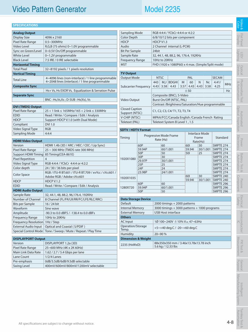
SPECIFICATIONS
Analog OutputDisplay Size 4096 x 2160Pixel Rate Range 0.5~300MHzVideo Level R,G,B (75 ohms) 0~1.0V programmableSync on Green/Level 0~0.5V On/Off programmableWhite Level 0~1.2V programmableBlack Level 7.5 IRE / 0 IRE selectableHorizontal TimingTotal Pixel 32~8192 pixels / 1 pixels resolutionVertical Timing
Total Line 4~4096 lines (non-interlace) / 1 line programmable 4~2048 lines (interlace) / 1 line programmable
Composite Sync Hs+ Vs, Hs EXOR Vs, Equalization & Serration Pulse
Separate SyncBNC : Hs,Vs,Xs ; D-SUB : Hs(Xs), Vs
DVI (TMDS) OutputPixel Rate Range 25 < 1 link ≤ 165MHz/165 < 2 link ≤ 330MHz EDID Read / Write / Compare / Edit / AnalysisHDCP Support HDCP V.1.0 (with Dual Mode)Compliant DVI 1.0Video Signal Type RGBSampling Mode 4:4:4
Data Storage DeviceDefault 2000 timings + 2000 patternsInternal Memory 3000 timings + 3000 patterns + 1000 programsExternal Memory USB Host interfaceOthersAC Input 1Ø 100~240V ±10% VLN, 47~63HzOperation/Storage Temp. +5~+40 deg.C / -20~+60 deg.C
Humidity 20~90 %Dimension & Weight
2235 (HxWxD) 88x350x350 mm / 3.46x13.78x13.78 inch 5.6 kg / 12.33 lbs
Sampling Mode RGB 4:4:4 / YCbCr 4:4:4 or 4:2:2Color Depth 6/8/10/12 bits per componentHDCP HDCP V1.3Audio 2 Channel internal (L-PCM)Bit Per Sample 24bitSample Rate 32, 44.1, 48, 88.2, 96, 176.4, 192KHzFrequency Range 10Hz to 20KHzMST FHD (1920 x 1080P60) x 4 max. (Simple/Split mode)
HDMI Video OutputVersion HDMI 1.4b (3D / ARC / HEC / CEC / Lip Sync)Pixel Rate Range 25 ~ 300 MHz (TMDS rate 300 MHz)Support HDMI Timing 85 Timing(CEA-861E)Pixel Repetition 4Video Signal Type RGB 4:4:4 / YCbCr 4:4:4 or 4:2:2Color depth 24 / 30 / 36 bits per pixel
Color SpaceRGB / ITU-R BT.601 / ITU-R BT.709 / xvYcc / sYcc601 / Adobe RGB / Adobe sYcc601
HDCP HDCP V.1.2EDID Read / Write / Compare / Edit / AnalysisHDMI Audio OutputSample Rate 32, 44.1, 48, 88.2, 96,176.4, 192KHzNumber of Channel 8 Channel (FL/FR/LR/RR/FC/LFE/RLC/RRC)Bits per Sample 16 / 24 bitWaveform Sine waveAmplitude -90.3 to 0.0 dBFS / -138.4 to 0.0 dBFsFrequency Range 10Hz to 20KHzFrequency Resolution 1Hz / StepExternal Audio Input Optical and Coaxial ( S/PDIF )Special Control Mode Tone / Sweep / Mute / Repeat / Play Time
TV OutputOutput Mode NTSC PAL SECAM
Subcarrier Frequency4434.43
M,J3.58
BDGHI4.43
M3.57
604.43
N4.43
Nc3.58
4.41/4.25
MHz
±50 Hz
Video OutputComposite (BNC), S-VideoBurst On/Off (NTSC, PAL)Contrast /Brightness/Saturation/Hue programmable
Closed Caption Support (NTSC) C1, C2, C3, C4/ T1, T2, T3, T4
V-CHIP (NTSC) MPAA/FCC/Canada English /Canada French RatingTeletext (PAL) Teletext System B Level 1 , 1.5
DISPLAYPORT OutputVersion DISPLAYPORT 1.2a (3D)Pixel Rate Range 25~600 MHz (4K x 2K 60Hz)Main Link Data Rate 1.62 / 2.7 / 5.4 Gbps per laneLane Count 1/2/4 LanesPre-emphasis 0dB/3.5dB/6dB/9.5dB selectableSwing Level 400mV/600mV/800mV/1200mV selectable
SDTV / HDTV Format
Timing Progressive Mode FrameRate (Hz)
Interlace Mode Frame
Rate(Hz)Standard
1920X1080
60P 60 60I 30 SMPTE 274 59.94P 60/1.001 59.94I 30/1.001 SMPTE 274 50P 50 50I 25 SMPTE 274 30P 30 SMPTE 274 29.97P 30/1.001 SMPTE 274 25P 25 SMPTE 274 24P 24 SMPTE 274 23.98P 24/1.001 SMPTE 274
1920X1035 60I 30 SMPTE 240 59.94I 30/1.001 SMPTE 240
1280X720 60P 60 SMPTE 296 59.94P 60/1.001 SMPTE 296 50P 50 SMPTE 296
4-9 All specifications are subject to change without notice. All specifications are subject to change without notice.
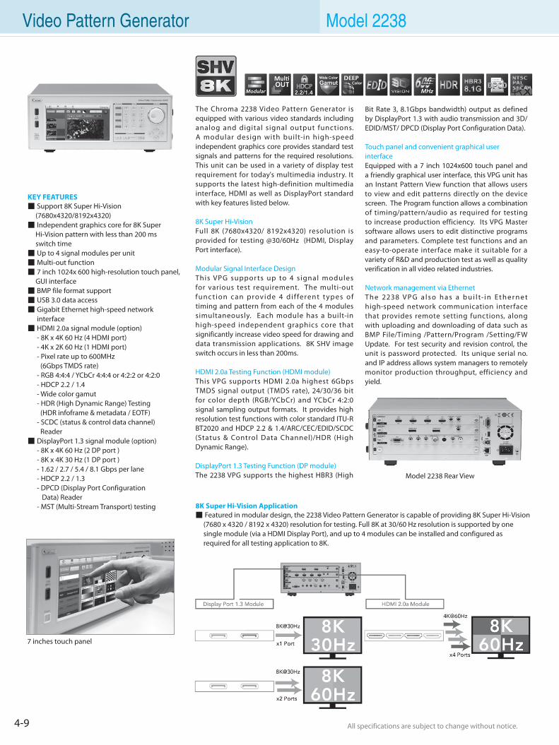
Video Pattern Generator Model 2238
Model 2238 Rear View
KEY FEATURES Support 8K Super Hi-Vision (7680x4320/8192x4320) Independent graphics core for 8K Super Hi-Vision pattern with less than 200 ms switch time Up to 4 signal modules per unit Multi-out function 7 inch 1024x 600 high-resolution touch panel, GUI interface BMP file format support USB 3.0 data access Gigabit Ethernet high-speed network interface HDMI 2.0a signal module (option) - 8K x 4K 60 Hz (4 HDMI port) - 4K x 2K 60 Hz (1 HDMI port) - Pixel rate up to 600MHz (6Gbps TMDS rate) - RGB 4:4:4 / YCbCr 4:4:4 or 4:2:2 or 4:2:0 - HDCP 2.2 / 1.4 - Wide color gamut - HDR (High Dynamic Range) Testing (HDR infoframe & metadata / EOTF) - SCDC (status & control data channel) Reader DisplayPort 1.3 signal module (option) - 8K x 4K 60 Hz (2 DP port ) - 8K x 4K 30 Hz (1 DP port ) - 1.62 / 2.7 / 5.4 / 8.1 Gbps per lane - HDCP 2.2 / 1.3 - DPCD (Display Port Configuration Data) Reader - MST (Multi-Stream Transport) testing
The Chroma 2238 Video Pattern Generator is equipped with various video standards including analog and digital signal output functions. A modular design with built-in high-speed independent graphics core provides standard test signals and patterns for the required resolutions. This unit can be used in a variety of display test requirement for today's multimedia industry. It supports the latest high-definition multimedia interface, HDMI as well as DisplayPort standard with key features listed below. 8K Super Hi-Vision Full 8K (7680x4320/ 8192x4320) resolution is provided for testing @30/60Hz (HDMI, Display Port interface).
Modular Signal Interface DesignThis VPG suppor ts up to 4 s ignal modules for various test requirement. The multi-out func t ion can provide 4 d i f ferent t ypes of timing and pattern from each of the 4 modules simultaneously. Each module has a built-in high-speed independent graphics core that significantly increase video speed for drawing and data transmission applications. 8K SHV image switch occurs in less than 200ms.
HDMI 2.0a Testing Function (HDMI module)This VPG supports HDMI 2.0a highest 6Gbps TMDS signal output (TMDS rate), 24/30/36 bit for color depth (RGB/YCbCr) and YCbCr 4:2:0 signal sampling output formats. It provides high resolution test functions with color standard ITU-R BT2020 and HDCP 2.2 & 1.4/ARC/CEC/EDID/SCDC (Status & Control Data Channel)/HDR (High Dynamic Range).
DisplayPort 1.3 Testing Function (DP module)The 2238 VPG supports the highest HBR3 (High
7 inches touch panel
Bit Rate 3, 8.1Gbps bandwidth) output as defined by DisplayPort 1.3 with audio transmission and 3D/EDID/MST/ DPCD (Display Port Configuration Data).
Touch panel and convenient graphical user interface Equipped with a 7 inch 1024x600 touch panel and a friendly graphical user interface, this VPG unit has an Instant Pattern View function that allows users to view and edit patterns directly on the device screen. The Program function allows a combination of timing/pattern/audio as required for testing to increase production efficiency. Its VPG Master software allows users to edit distinctive programs and parameters. Complete test functions and an easy-to-operate interface make it suitable for a variety of R&D and production test as well as quality verification in all video related industries.
Network management via EthernetTh e 2238 V P G a l s o h a s a b u i l t-i n E t h e r n e t high-speed network communication interface that provides remote setting functions, along with uploading and downloading of data such as BMP File/Timing /Pattern/Program /Setting/FW Update. For test security and revision control, the unit is password protected. Its unique serial no. and IP address allows system managers to remotely monitor production throughput, efficiency and yield.
8K Super Hi-Vision Application Featured in modular design, the 2238 Video Pattern Generator is capable of providing 8K Super Hi-Vision (7680 x 4320 / 8192 x 4320) resolution for testing. Full 8K at 30/60 Hz resolution is supported by one single module (via a HDMI Display Port), and up to 4 modules can be installed and configured as required for all testing application to 8K.
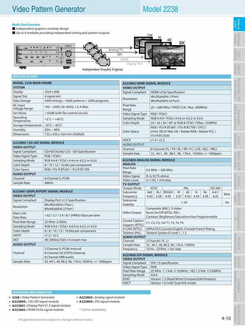
4-10All specifications are subject to change without notice. All specifications are subject to change without notice.
Flat PanelD
isplayPow
er Electronics
Electrical Safety
General
PurposePassive
Component
Semiconductor/
ICBattery Test & Autom
ationAutom
atedO
ptical Inspection Photovoltaic Test
& Automation
PXI Test &
Measurem
ent Video & Color
LED/
LightingO
ptical D
evicesIntelligent
Manufacturing System
Turnkey Test & Autom
ation Video Pattern Generator Model 2238
2238 : Video Pattern GeneratorA223800 : 12G-SDI signal moduleA223801 : Display Port V1.3 signal moduleA223802 : HDMI V2.0a signal module
A223803 : Analog signal moduleA223806 : DVI signal module
* Call for availability
Multi-Out Function Independent graphics modular design Up to 4 modules providing independent timing and pattern outputs
ORDERING INFORMATION
SPECIFICATIONS
A223801 DISPLAYPORT SIGNAL MODULEVIDEO OUTPUTSignal Compliant Display Port v1.3 Specification
Resolution8Kx4K@30Hz (1Port )8Kx4K@60Hz (2 Port )
Main LinkData Rate
1.62 / 2.7 / 5.4 / 8.1 (HRB3) Gbps per lane
Pixel Rate Range 25 MHz~2.4GHzSampling Mode RGB 4:4:4 / YCbCr 4:4:4 or 4:2:2 or 4:2:0Color Depth 6 / 8 / 10 / 12 / 16 bits per componentHDCP v1.3 / v2.2MST 4K (3840x2160) x 4 stream maxAUDIO OUTPUT
Channel2 Channel (L-PCM)-Internal8 Channel (AC3/DTS)-External8 Channel HBR-audio
Sample Rate 32, 44.1, 48, 88.2, 96, 176.4, 192KHz, +/- 1000ppm
A223800 12G-SDI SIGNAL MODULEVIDEO OUTPUTSignal Compliant SD/HD/3G/6G/12G - SDI SpecificationVideo Signal Type RGB / YCbCrSampling Mode RGB 4:4:4 / YCbCr 4:4:4 or 4:2:2 or 4:2:0Color Depth 8 / 10 / 12 / 16 bits per componentColor Space RGB / ITU-R BT.601 / ITU-R BT.709AUDIO OUTPUTChannel 8 Channel (L-PCM)Sample Rate 48KHz
A223806 DVI SIGNAL MODULEVIDEO OUTPUTSignal Compliant DVI 1.0 specificationVideo Signal Type RGBPixel Rate Range 25 MHz <1 link ≦165MHz ; 165<2 link ≦330MHzSampling Mode 4:4:4EDID Version 1.3 (Read/Write/Compare/Edit/Analysis)HDCP Version 1.0 (with Dual-link mode)
A223802 HDMI SIGNAL MODULEVIDEO OUTPUTSignal Compliant HDMI v2.0a Specification
Resolution4Kx2K@60Hz (1Port)8Kx4K@60Hz (4 Port)
Pixel RateRange
25 ~ 600 MHz ( TMDS CLK : Max. 300MHz)
Video Signal Type RGB / YCbCrSampling Mode RGB 4:4:4 / YCbCr 4:4:4 or 4:2:2 or 4:2:0Color Depth 24 / 30 / 36 / 48* @ RGB & YCbCr (*Max. 150MHz)
Color SpaceRGB / ITU-R BT.601 / ITU-R BT.709 / SYCC/ xvYcc (IEC61966-24) / Adobe RGB / Adobe YCC / ITU-R BT.2020
HDCP v1.4 / v2.2AUDIO OUTPUTChannel 8 Channel (FL / FR / RL / RR / FC / LFE / RLC / RRC)Sample Rate 32 , 44.1 , 48 , 88.2 , 96 , 176.4 , 192KHz +/- 1000ppm
A223803 ANALOG SIGNAL MODULEANALOGPixel Rate Range
0.5 MHz ~ 300 MHz
Video Signal R, G, B (75 ohms)Video Level 0~1.0V, 1 mV/stepTV OUTPUTOutput Mode NTSC PAL SECAMSubcarrier Frequency
4434.43
M,J3.58
BDGHI4.43
M3.57
604.43
N4.43
Nc3.58
4.41/4.25
MHz
SubcarrierStability ±50 Hz
Video Output Composite (BNC), S-VideoBurst On/Off (NTSC, PAL)Contrast /Brightness/Saturation/Hue Programmable
Closed Caption Support (NTSC)
C1, C2, C3, C4/ T1, T2, T3, T4
V-CHIP (NTSC) MPAA/FCC/Canada English /Canada French RatingTeletext (PAL) Teletext System B Level 1 , 1.5AUDIO OUTPUTChannel 2 Channel ( R , L)Sample Rate 32 , 44.1, 48, 88.2, 96, 176.4, 192KHzFrequency 10 Hz ~20 KHz, 1 Hz/ step
****
**
MODEL 2238 MAIN FRAMESYSTEMDisplay 1024 x 600Signal Slot 4 signal slotData Storage 5000 timings + 5000 patterns + 2000 programsAC inputVoltage Range 100 ~ 240V, 50~60Hz, 1.5 A Max.
Fan Noise < 65dB (with fan control circuit)Operating Temperature +5 ~ +40
Storage temperature -20 ~ 60Humidity 20% ~ 90%Dimensions 132 x 350 x 350 mm (HxWxD)
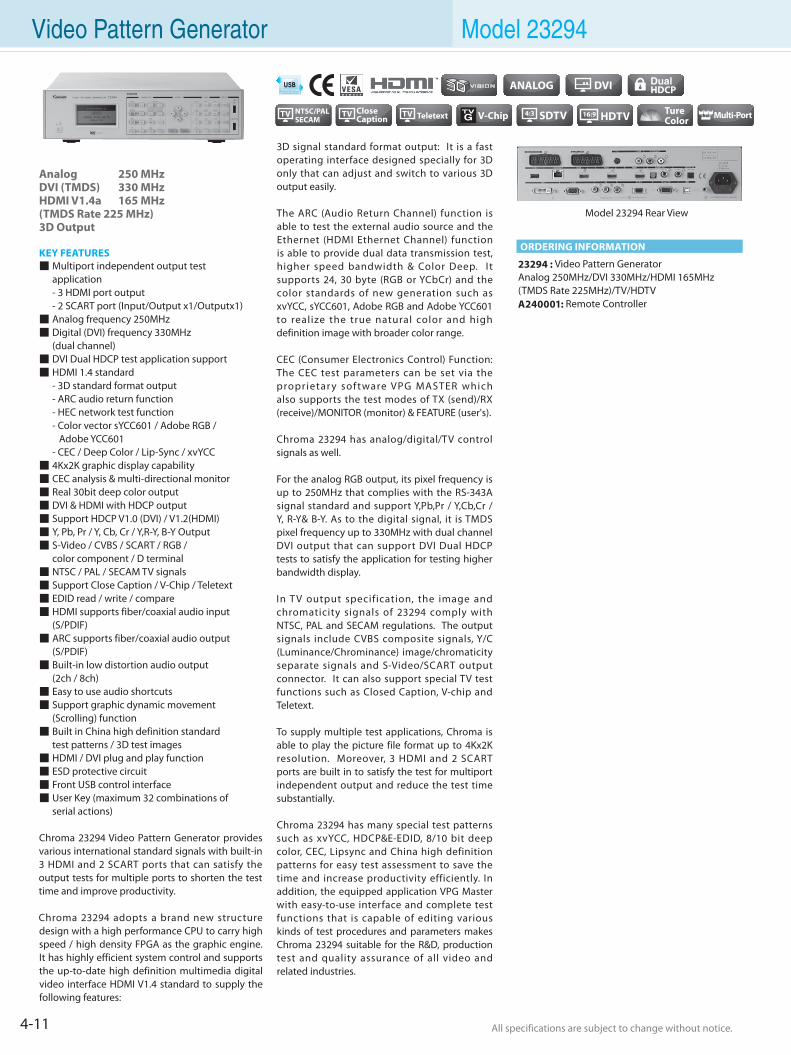
4-11 All specifications are subject to change without notice. All specifications are subject to change without notice.
Video Pattern Generator Model 23294
Analog 250 MHzDVI (TMDS) 330 MHzHDMI V1.4a 165 MHz(TMDS Rate 225 MHz)3D Output
KEY FEATURES Multiport independent output test application - 3 HDMI port output - 2 SCART port (Input/Output x1/Outputx1) Analog frequency 250MHz Digital (DVI) frequency 330MHz (dual channel) DVI Dual HDCP test application support HDMI 1.4 standard - 3D standard format output - ARC audio return function - HEC network test function - Color vector sYCC601 / Adobe RGB / Adobe YCC601 - CEC / Deep Color / Lip-Sync / xvYCC 4Kx2K graphic display capability CEC analysis & multi-directional monitor Real 30bit deep color output DVI & HDMI with HDCP output Support HDCP V1.0 (DVI) / V1.2(HDMI) Y, Pb, Pr / Y, Cb, Cr / Y,R-Y, B-Y Output S-Video / CVBS / SCART / RGB / color component / D terminal NTSC / PAL / SECAM TV signals Support Close Caption / V-Chip / Teletext EDID read / write / compare HDMI supports fiber/coaxial audio input (S/PDIF) ARC supports fiber/coaxial audio output (S/PDIF) Built-in low distortion audio output (2ch / 8ch) Easy to use audio shortcuts Support graphic dynamic movement (Scrolling) function Built in China high definition standard test patterns / 3D test images HDMI / DVI plug and play function ESD protective circuit Front USB control interface User Key (maximum 32 combinations of serial actions)
Chroma 23294 Video Pattern Generator provides various international standard signals with built-in 3 HDMI and 2 SCART ports that can satisfy the output tests for multiple ports to shorten the test time and improve productivity.
Chroma 23294 adopts a brand new structure design with a high performance CPU to carry high speed / high density FPGA as the graphic engine. It has highly efficient system control and supports the up-to-date high definition multimedia digital video interface HDMI V1.4 standard to supply the following features:
3D signal standard format output: It is a fast operating interface designed specially for 3D only that can adjust and switch to various 3D output easily.
The ARC (Audio Return Channel) function is able to test the external audio source and the Ethernet (HDMI Ethernet Channel) function is able to provide dual data transmission test, higher speed bandwidth & Color Deep. I t supports 24, 30 byte (RGB or YCbCr) and the color standards of new generation such as xvYCC, sYCC601, Adobe RGB and Adobe YCC601 to realize the true natural color and high definition image with broader color range.
CEC (Consumer Electronics Control) Function: The CEC test parameters can be set via the proprietar y software VPG MASTER which also supports the test modes of TX (send)/RX (receive)/MONITOR (monitor) & FEATURE (user's).
Chroma 23294 has analog/digital/TV control signals as well.
For the analog RGB output, its pixel frequency is up to 250MHz that complies with the RS-343A signal standard and support Y,Pb,Pr / Y,Cb,Cr / Y, R-Y& B-Y. As to the digital signal, it is TMDS pixel frequency up to 330MHz with dual channel DVI output that can support DVI Dual HDCP tests to satisfy the application for testing higher bandwidth display.
In T V output specification, the image and chromaticity signals of 23294 comply with NTSC, PAL and SECAM regulations. The output signals include CVBS composite signals, Y/C (Luminance/Chrominance) image/chromaticity separate signals and S-Video/SCART output connector. It can also support special TV test functions such as Closed Caption, V-chip and Teletext.
To supply multiple test applications, Chroma is able to play the picture file format up to 4Kx2K resolution. Moreover, 3 HDMI and 2 SCART ports are built in to satisfy the test for multiport independent output and reduce the test time substantially.
Chroma 23294 has many special test patterns such as xvYCC, HDCP&E-EDID, 8/10 bit deep color, CEC, Lipsync and China high definition patterns for easy test assessment to save the time and increase productivity efficiently. In addition, the equipped application VPG Master with easy-to-use interface and complete test functions that is capable of editing various kinds of test procedures and parameters makes Chroma 23294 suitable for the R&D, production test and quality assurance of all video and related industries.
23294 : Video Pattern GeneratorAnalog 250MHz/DVI 330MHz/HDMI 165MHz (TMDS Rate 225MHz)/TV/HDTVA240001: Remote Controller
TV NTSC/PALSECAM
ORDERING INFORMATION
Model 23294 Rear View
4-12All specifications are subject to change without notice. All specifications are subject to change without notice.
Flat PanelD
isplayPow
er Electronics
Electrical Safety
General
PurposePassive
Component
Semiconductor/
ICBattery Test & Autom
ationAutom
atedO
ptical Inspection Photovoltaic Test
& Automation
PXI Test &
Measurem
ent Video & Color
LED/
LightingO
ptical D
evicesIntelligent
Manufacturing System
Turnkey Test & Autom
ation Video Pattern Generator Model 23294
ANALOG OUTPUTDisplay Size 4096 x 2160Pixel Rate Range 0.5~250MHzVideo Level R,G,B (75 ohms) 0~1.0V programmableSync on Green / Level 0~0.5V On/Off programmableWhite Level 0~1.2V programmableBlack Level 7.5 IRE / 0 IRE selectableHORIZONTAL TIMINGTotal Pixels 32~8192 pixels / 1 pixels resolutionVERTICAL TIMING
Total Pixels 4~4096 lines (non-interlace)4~2048 lines (interlace) / 1 line programmable
COMPOSITE SYNC H+V, H EXOR V, Equalization & Serration PulseSEPARATE SYNC D-SUB: Hs (Xs), VsVIDEO FORMAT
Video Output
R, G, B / RS-343A / RS-170 / VESA (VSIS)Y, R-Y, B-YY, Cb, Cr / ITU 601Y, Pb, Pr / ITU 709, RP 177, SMPTE 240MDDC II B (D-SUB)
DVI (TMDS) OUTPUTPixel Rate Range 25 < 1 link ≤ 165MHz/165 < 2 link ≤ 330MHz E-EDID Read / Write / Compare / EditHDCP Support HDCP V1.0 (with Dual Mode)Compliant DVI 1.0 specificationVideo Signal Type RGBSampling Mode 4:4:4
DATA STORAGE DEVICEDefault 2000 timings + 2000 patternsInternal Memory 3000 timings + 3000 patterns + 1000 programsExternal Memory USB Host interfaceOTHERSAC Input 1Ø 100~240V ±10% VLN, 47~63HzOperation/Storage Temp. +5~+40 deg.C / -20~+60 deg.CHumidity 20~90 %DIMENSION23293-B (H x W x D) 88 x 350 x 350 mm / 3.46 x 13.78 x 13.78 inchWEIGHT23294 4.5 kg / 9.9 lbs
TV OUTPUTOutput Mode NTSC PAL SECAM
Subcarrier Frequency 4434.43
M,J3.58
BDGHI4.43
M3.57
604.43
N4.43
Nc3.58 4.41/4.25 MHz
Subcarrier Stability ±50 Hz
Video Output
Composite (RCA), S-VideoBurst On/Off (NTSC, PAL)Contrast programmableBrightness programmableSaturation programmableHue programmable
Closed Caption Support (NTSC) C1, C2, C3, C4/ T1, T2, T3, T4
V-CHIP (NTSC)
MPAA Rating : G, PG, PG-13, R, NC-17, XFCC Rating : TV-Y, TV-Y7, TV-G, TV-PG, TV-14, TV-MACanada English Rating : C, C8+, G, PG, 14+, 18+Canada French Rating : G, 8 ans+, 13 ans+, 16 ans+, 18 ans+
Teletext (PAL) Teletext System B Level 1 , 1.5
HDMI VIDEO OUTPUT
Version HDMI V1.4a (3D Format / ARC / HEC / CEC / Lip Sync)
Pixel Rate Range 25 ~ 165 MHz (TMDS rate 225MHz)Support HDMI Timing 85 Timing(CEA-861E)Pixel Repetition 4Video Signal Type RGB or YCbCrSampling Mode RGB 4:4:4 / YCbCr 4:4:4 or 4:2:2Bits per Component 8 / 10 / 12 @RGB & YCbCr
Color Space RGB / ITU-R BT.601 / ITU-R BT.709 / xvYCC (IEC61966-2-4) / sYcc601 / Adobe RGB / Adobe sYcc601
HDCP Support HDCP V.1.2EDID Read / Write / Compare / EditHDMI AUDIO OUTPUTSample Rate 32,44.1,48,88.2, 96,176.4, 192KHzNumber of Channel 8 Channel (FL/FR/RL/RR/FC/LFE/RLC/RRC)Bits per Sample 16 / 24 bitWaveform Sine waveAmplitude -90.3 to 0.0 dBFS / -138.4 to 0.0 dBFSFrequency Range 10Hz to 20KHzFrequency Resolution 10Hz / StepExternal Audio Input Optical and Coaxial ( S/PDIF )Special Control Mode Tone / Sweep / Mute / Repeat / Play Time
HDTV FORMAT
Timing Progressive Mode Frame Rate (Hz)
Interlace Mode Frame Rate (Hz) Standard
1920 x 1080
60P 60 60I 30 SMPTE 27459.94P 60/1.001 59.94I 30/1.001 SMPTE 274
50P 50 50I 25 SMPTE 27430P 30 SMPTE 274
29.97P 30/1.001 SMPTE 27425P 25 SMPTE 27424P 24 SMPTE 274
23.98P 24/1.001 SMPTE 274
1920 x 1035 60I 30 SMPTE 240
59.94I 30/1.001 SMPTE 240
1280 x 720 60P 60 SMPTE 296
59.94P 60/1.001 SMPTE 29650P 50 SMPTE 296
SPECIFICATIONS
3D VIDEO FORMAT OUTPUT
3D Scanning Mode
Frame packing Field alternativeLine alternativeSide-by-Side (Full)L + depthL + depth + graphics + graphics-depthTop & BottomSide-by-Side (Half )
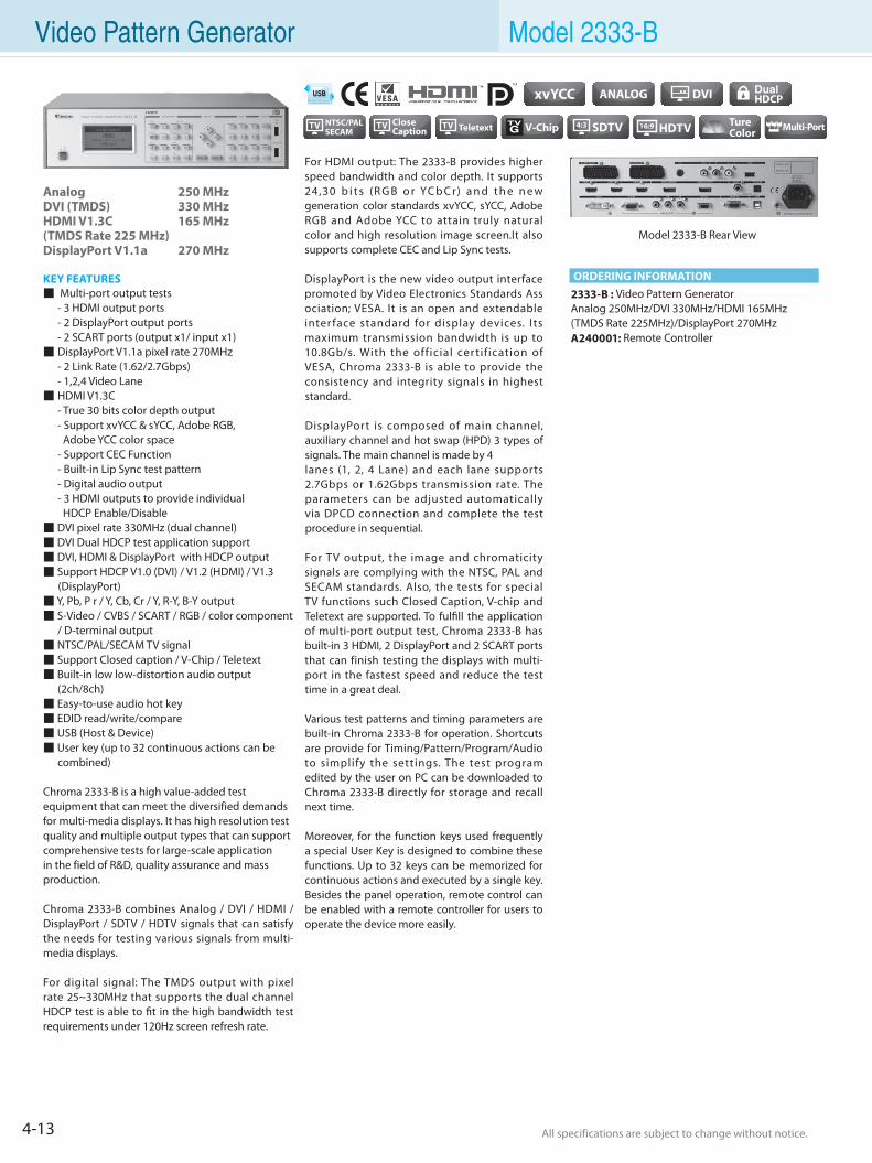
4-13 All specifications are subject to change without notice. All specifications are subject to change without notice.
Video Pattern Generator Model 2333-B
Analog 250 MHzDVI (TMDS) 330 MHzHDMI V1.3C 165 MHz(TMDS Rate 225 MHz) DisplayPort V1.1a 270 MHz
KEY FEATURES Multi-port output tests - 3 HDMI output ports - 2 DisplayPort output ports - 2 SCART ports (output x1/ input x1) DisplayPort V1.1a pixel rate 270MHz - 2 Link Rate (1.62/2.7Gbps) - 1,2,4 Video Lane HDMI V1.3C - True 30 bits color depth output - Support xvYCC & sYCC, Adobe RGB, Adobe YCC color space - Support CEC Function - Built-in Lip Sync test pattern - Digital audio output - 3 HDMI outputs to provide individual HDCP Enable/Disable DVI pixel rate 330MHz (dual channel) DVI Dual HDCP test application support DVI, HDMI & DisplayPort with HDCP output Support HDCP V1.0 (DVI) / V1.2 (HDMI) / V1.3 (DisplayPort) Y, Pb, P r / Y, Cb, Cr / Y, R-Y, B-Y output S-Video / CVBS / SCART / RGB / color component / D-terminal output NTSC/PAL/SECAM TV signal Support Closed caption / V-Chip / Teletext Built-in low low-distortion audio output (2ch/8ch) Easy-to-use audio hot key EDID read/write/compare USB (Host & Device) User key (up to 32 continuous actions can be combined)
Chroma 2333-B is a high value-added test equipment that can meet the diversified demands for multi-media displays. It has high resolution test quality and multiple output types that can support comprehensive tests for large-scale application in the field of R&D, quality assurance and mass production.
Chroma 2333-B combines Analog / DVI / HDMI / DisplayPort / SDTV / HDTV signals that can satisfy the needs for testing various signals from multi-media displays.
For digital signal: The TMDS output with pixel rate 25~330MHz that supports the dual channel HDCP test is able to fit in the high bandwidth test requirements under 120Hz screen refresh rate.
For HDMI output: The 2333-B provides higher speed bandwidth and color depth. It supports 24,30 b i t s (R G B o r YC b C r) a n d t h e n e w generation color standards xvYCC, sYCC, Adobe RGB and Adobe YCC to attain truly natural color and high resolution image screen.It also supports complete CEC and Lip Sync tests.
DisplayPort is the new video output interface promoted by Video Electronics Standards Ass ociation; VESA. It is an open and extendable inter face standard for display devices. I ts maximum transmission bandwidth is up to 10.8Gb/s. With the official certif ication of VESA, Chroma 2333-B is able to provide the consistency and integrity signals in highest standard.
DisplayPort is composed of main channel, auxiliary channel and hot swap (HPD) 3 types of signals. The main channel is made by 4lanes (1, 2, 4 Lane) and each lane supports 2.7Gbps or 1.62Gbps transmission rate. The parameters can be adjusted automatically via DPCD connection and complete the test procedure in sequential.
For TV output, the image and chromaticity signals are complying with the NTSC, PAL and SECAM standards. Also, the tests for special TV functions such Closed Caption, V-chip and Teletext are supported. To fulfill the application of multi-port output test, Chroma 2333-B has built-in 3 HDMI, 2 DisplayPort and 2 SCART ports that can finish testing the displays with multi-port in the fastest speed and reduce the test time in a great deal.
Various test patterns and timing parameters are built-in Chroma 2333-B for operation. Shortcuts are provide for Timing/Pattern/Program/Audio to simplify the settings. The test program edited by the user on PC can be downloaded to Chroma 2333-B directly for storage and recall next time.
Moreover, for the function keys used frequently a special User Key is designed to combine these functions. Up to 32 keys can be memorized for continuous actions and executed by a single key. Besides the panel operation, remote control can be enabled with a remote controller for users to operate the device more easily.
2333-B : Video Pattern GeneratorAnalog 250MHz/DVI 330MHz/HDMI 165MHz (TMDS Rate 225MHz)/DisplayPort 270MHzA240001: Remote Controller
Model 2333-B Rear View
ORDERING INFORMATION
TV NTSC/PALSECAM
4-14All specifications are subject to change without notice. All specifications are subject to change without notice.
Flat PanelD
isplayPow
er Electronics
Electrical Safety
General
PurposePassive
Component
Semiconductor/
ICBattery Test & Autom
ationAutom
atedO
ptical Inspection Photovoltaic Test
& Automation
PXI Test &
Measurem
ent Video & Color
LED/
LightingO
ptical D
evicesIntelligent
Manufacturing System
Turnkey Test & Autom
ation Video Pattern Generator Model 2333-B
AUDIO (ANALOG) OUTPUTNumber of Channel 2 Channel (R / L)Sample Rate 32, 44.1 , 48 , 88.2 , 96 , 176.4 , 192KHzLevel Resolution 10mV / StepLevel Range 0V to 2V (at 600 Ohms Load)Frequency Range 10Hz to 20KHz / 10Hz StepSpecial Control Mode Tone / Sweep / Mute / Repeat / Play Time
ANALOG OUTPUTDisplay Size 4096 x 2160Pixel Rate Range 0.5~250MHzVideo Level R,G,B (75 ohms) 0~1.0V programmableSync on Green / Level 0~0.5V On/Off programmableWhite Level 0~1.2V programmableBlack Level 7.5 IRE / 0 IRE selectableHORIZONTAL TIMINGTotal Pixels 32~8192 pixels / 1 pixels resolutionVERTICAL TIMING
Total Pixels 4~4096 lines (non-interlace)4~2048 lines (interlace) / 1 line programmable
COMPOSITE SYNC H+V, H EXOR V, Equalization & Serration PulseSEPARATE SYNC D-SUB: Hs (Xs), VsVIDEO FORMAT
Video Output
R, G, B / RS-343A / RS-170 / VESA (VSIS)Y, R-Y, B-YY, Cb, Cr / ITU 601Y, Pb, Pr / ITU 709, RP 177, SMPTE 240MDDC II B (D-SUB)
DVI (TMDS) OUTPUTPixel Rate Range 25 < 1 link ≤ 165MHz/165 < 2 link ≤ 330MHz E-EDID Read / Write / Compare / EditHDCP Support HDCP V1.0 (with Dual Mode)Compliant DVI 1.0 specificationVideo Signal Type RGBSampling Mode 4:4:4
DATA STORAGE DEVICEDefault 2000 timings + 2000 patternsInternal Memory 3000 timings + 3000 patterns + 1000 programsExternal Memory USB Host interfaceOTHERSAC Input 1Ø 100~240V ±10% VLN, 47~63HzOperation/Storage Temp. +5~+40 deg.C / -20~+60 deg.CHumidity 20~90 %DIMENSION2333-B (H x W x D) 88 x 350 x 350 mm / 3.46 x 13.78 x 13.78 inchWEIGHT2333-B 4.5 kg / 9.9 lbs
TV OUTPUTOutput Mode NTSC PAL SECAM
Subcarrier Frequency 4434.43
M,J3.58
BDGHI4.43
M3.57
604.43
N4.43
Nc3.58 4.41/4.25 MHz
Subcarrier Stability ±50 Hz
Video Output
S-Video, RCABurst On/Off (NTSC, PAL)Contrast programmableBrightness programmableSaturation programmableHue programmable
Closed Caption Support (NTSC) C1, C2, C3, C4/ T1, T2, T3, T4
V-CHIP (NTSC)
MPAA Rating : G, PG, PG-13, R, NC-17, XFCC Rating : TV-Y, TV-Y7, TV-G, TV-PG, TV-14, TV-MACanada English Rating : C, C8+, G, PG, 14+, 18+Canada French Rating : G, 8 ans+, 13 ans+, 16 ans+, 18 ans+
Teletext (PAL) Teletext System B Level 1 , 1.5
HDMI VIDEO OUTPUT
Version HDMI V1.3C(with 24,30 bit deep color/xvYCC/CEC/Lip Sync)
Pixel Rate Range 25 ~ 165 MHz ( TMDS CLK : 225MHz)Support HDMI Timing 77 Timing(CEA-861D)Pixel Repetition 4Video Signal Type RGB or YCbCrSampling Mode RGB 4:4:4 / YCbCr 4:4:4 or 4:2:2Bits per Component 8 / 10 @RGB & YCbCr
Color Space RGB/ITU-R BT.601/ITU-R BT.709/xvYCC (IEC61966-2-4) /sYCC 601/Adobe RGB/Adobe YCC 601
HDCP Support HDCP V.1.2EDID Read / Write / Compare / EditHDMI AUDIO OUTPUTSample Rate 32,44.1,48,88.2, 96,176.4, 192KHzNumber of Channel 8 Channel (FL/FR/RL/RR/FC/LFE/RLC/RRC)Bits per Sample 16 / 24 bitWaveform Sine waveAmplitude -90.3 to 0.0 dBFS / -138.4 to 0.0 dBFSFrequency Range 10Hz to 20KHzFrequency Resolution 10Hz / StepExternal Audio Input Optical and Coaxial ( S/PDIF )Special Control Mode Tone / Sweep / Mute / Repeat / Play Time
DISPLAYPORT OUTPUTVersion DisplayPort 1.1aPixel Rate Range 25~270MHzVideo Signal Type RGB/YCbCrSampling Mode RGB 4:4:4 / YCbCr 4:4:4 or 4:2:2Color Depth Transmission
6/8/10 bits per component
HDCP HDCP V1.3DPCD Read / WriteMain Link Data Rate 2.7Gbps or 1.62Gbps per laneLane Count 1/2/4 LanesAudio 2 Channel (L-PCM)-InternalBit Per Sample 24bitSample Rate 32, 44.1, 48, 88.2, 96, 176.4, 192KHz
SPECIFICATIONS
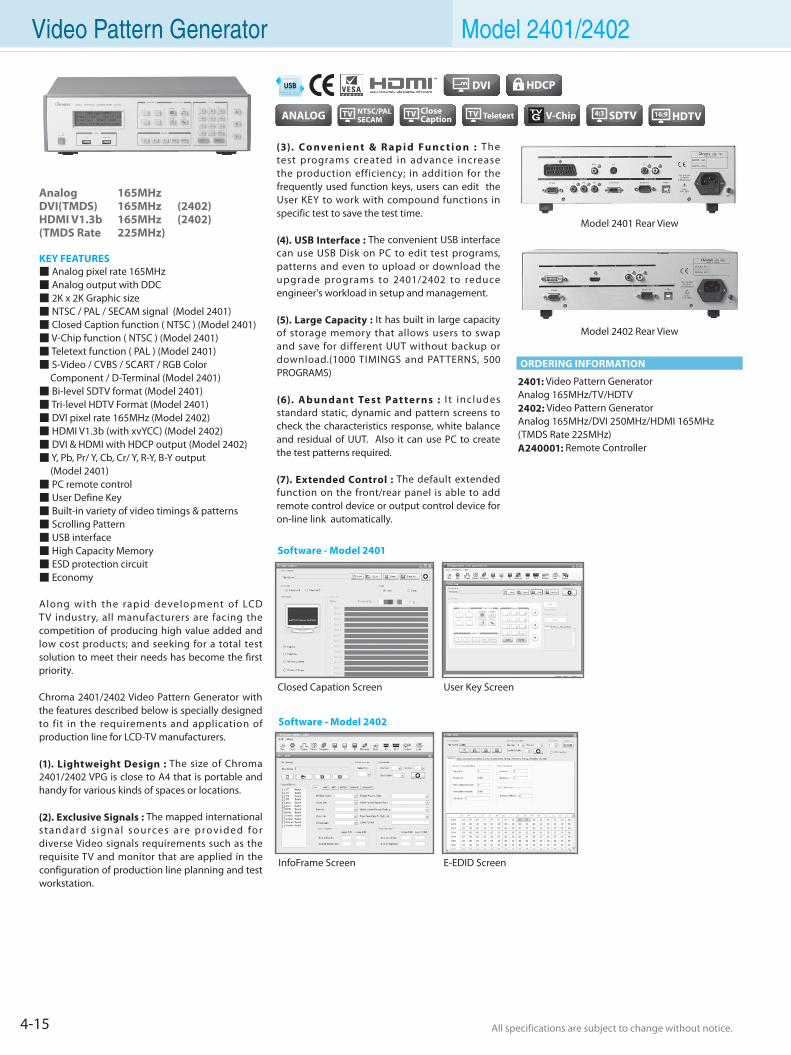
4-15 All specifications are subject to change without notice. All specifications are subject to change without notice.
Video Pattern Generator Model 2401/2402
Analog 165MHzDVI(TMDS) 165MHz (2402)HDMI V1.3b 165MHz (2402) (TMDS Rate 225MHz)
KEY FEATURES Analog pixel rate 165MHz Analog output with DDC 2K x 2K Graphic size NTSC / PAL / SECAM signal (Model 2401) Closed Caption function ( NTSC ) (Model 2401) V-Chip function ( NTSC ) (Model 2401) Teletext function ( PAL ) (Model 2401) S-Video / CVBS / SCART / RGB Color Component / D-Terminal (Model 2401) Bi-level SDTV format (Model 2401) Tri-level HDTV Format (Model 2401) DVI pixel rate 165MHz (Model 2402) HDMI V1.3b (with xvYCC) (Model 2402) DVI & HDMI with HDCP output (Model 2402) Y, Pb, Pr/ Y, Cb, Cr/ Y, R-Y, B-Y output (Model 2401) PC remote control User Define Key Built-in variety of video timings & patterns Scrolling Pattern USB interface High Capacity Memory ESD protection circuit Economy
Along with the rapid development of LCD TV industry, all manufacturers are facing the competition of producing high value added and low cost products; and seeking for a total test solution to meet their needs has become the first priority.
Chroma 2401/2402 Video Pattern Generator with the features described below is specially designed to fit in the requirements and application of production line for LCD-TV manufacturers.
(1). Lightweight Design : The size of Chroma 2401/2402 VPG is close to A4 that is portable and handy for various kinds of spaces or locations.
(2). Exclusive Signals : The mapped international s t a n d a rd s i gn a l s o u rce s a re p rov i d e d fo r diverse Video signals requirements such as the requisite TV and monitor that are applied in the configuration of production line planning and test workstation.
(3). C o nve n i e n t & R a p i d Fu n c t i o n : The test programs created in advance increase the production efficiency; in addition for the frequently used function keys, users can edit the User KEY to work with compound functions in specific test to save the test time.
(4). USB Interface : The convenient USB interface can use USB Disk on PC to edit test programs, patterns and even to upload or download the upgrade programs to 2401/2402 to reduce engineer's workload in setup and management.
(5). Large Capacity : It has built in large capacity of storage memory that allows users to swap and save for different UUT without backup or download.(1000 TIMINGS and PATTERNS, 500 PROGRAMS)
(6). Ab u nd ant Te s t Pat te rns : I t includes standard static, dynamic and pattern screens to check the characteristics response, white balance and residual of UUT. Also it can use PC to create the test patterns required.
(7). Extended Control : The default extended function on the front/rear panel is able to add remote control device or output control device for on-line link automatically.
2401: Video Pattern GeneratorAnalog 165MHz/TV/HDTV2402: Video Pattern GeneratorAnalog 165MHz/DVI 250MHz/HDMI 165MHz (TMDS Rate 225MHz)A240001: Remote Controller
ORDERING INFORMATION
TV NTSC/PALSECAM
Model 2401 Rear View
Closed Capation Screen User Key Screen
Model 2402 Rear View
InfoFrame Screen E-EDID Screen
Software - Model 2401
Software - Model 2402
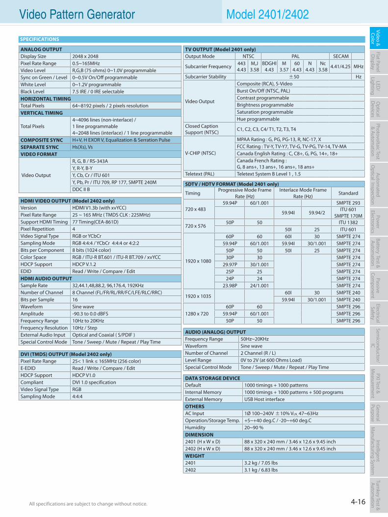
4-16All specifications are subject to change without notice. All specifications are subject to change without notice.
Flat PanelD
isplayPow
er Electronics
Electrical Safety
General
PurposePassive
Component
Semiconductor/
ICBattery Test & Autom
ationAutom
atedO
ptical Inspection Photovoltaic Test
& Automation
PXI Test &
Measurem
ent Video & Color
LED/
LightingO
ptical D
evicesIntelligent
Manufacturing System
Turnkey Test & Autom
ation Video Pattern Generator Model 2401/2402
AUDIO (ANALOG) OUTPUTFrequency Range 50Hz~20KHzWaveform Sine waveNumber of Channel 2 Channel (R / L)Level Range 0V to 2V (at 600 Ohms Load)Special Control Mode Tone / Sweep / Mute / Repeat / Play Time
ANALOG OUTPUTDisplay Size 2048 x 2048Pixel Rate Range 0.5~165MHzVideo Level R,G,B (75 ohms) 0~1.0V programmableSync on Green / Level 0~0.5V On/Off programmableWhite Level 0~1.2V programmableBlack Level 7.5 IRE / 0 IRE selectableHORIZONTAL TIMINGTotal Pixels 64~8192 pixels / 2 pixels resolutionVERTICAL TIMING
Total Pixels 4~4096 lines (non-interlace) / 1 line programmable4~2048 lines (interlace) / 1 line programmable
COMPOSITE SYNC H+V, H EXOR V, Equalization & Serration PulseSEPARATE SYNC Hs(Xs), VsVIDEO FORMAT
Video Output
R, G, B / RS-343AY, R-Y, B-YY, Cb, Cr / ITU 601Y, Pb, Pr / ITU 709, RP 177, SMPTE 240MDDC II B
DVI (TMDS) OUTPUT (Model 2402 only)Pixel Rate Range 25< 1 link ≤ 165MHz (256 color)E-EDID Read / Write / Compare / EditHDCP Support HDCP V1.0Compliant DVI 1.0 specificationVideo Signal Type RGBSampling Mode 4:4:4
DATA STORAGE DEVICEDefault 1000 timings + 1000 patternsInternal Memory 1000 timings + 1000 patterns + 500 programsExternal Memory USB Host interfaceOTHERSAC Input 1Ø 100~240V ±10% VLN, 47~63HzOperation/Storage Temp. +5~+40 deg.C / -20~+60 deg.CHumidity 20~90 %DIMENSION2401 (H x W x D) 88 x 320 x 240 mm / 3.46 x 12.6 x 9.45 inch2402 (H x W x D) 88 x 320 x 240 mm / 3.46 x 12.6 x 9.45 inchWEIGHT2401 3.2 kg / 7.05 lbs2402 3.1 kg / 6.83 lbs
TV OUTPUT (Model 2401 only)Output Mode NTSC PAL SECAM
Subcarrier Frequency 4434.43
M,J3.58
BDGHI4.43
M3.57
604.43
N4.43
Nc3.58 4.41/4.25 MHz
Subcarrier Stability ±50 Hz
Video Output
Composite (RCA), S-VideoBurst On/Off (NTSC, PAL)Contrast programmableBrightness programmableSaturation programmableHue programmable
Closed Caption Support (NTSC) C1, C2, C3, C4/ T1, T2, T3, T4
V-CHIP (NTSC)
MPAA Rating : G, PG, PG-13, R, NC-17, XFCC Rating : TV-Y, TV-Y7, TV-G, TV-PG, TV-14, TV-MACanada English Rating : C, C8+, G, PG, 14+, 18+Canada French Rating : G, 8 ans+, 13 ans+, 16 ans+, 18 ans+
Teletext (PAL) Teletext System B Level 1 , 1.5
HDMI VIDEO OUTPUT (Model 2402 only)Version HDMI V1.3b (with xvYCC)Pixel Rate Range 25 ~ 165 MHz ( TMDS CLK : 225MHz)Support HDMI Timing 77 Timing(CEA-861D)Pixel Repetition 4Video Signal Type RGB or YCbCrSampling Mode RGB 4:4:4 / YCbCr 4:4:4 or 4:2:2Bits per Component 8 bits (1024 color)Color Space RGB / ITU-R BT.601 / ITU-R BT.709 / xvYCCHDCP Support HDCP V.1.2EDID Read / Write / Compare / EditHDMI AUDIO OUTPUTSample Rate 32,44.1,48,88.2, 96,176.4, 192KHzNumber of Channel 8 Channel (FL/FR/RL/RR/FC/LFE/RLC/RRC)Bits per Sample 16Waveform Sine waveAmplitude -90.3 to 0.0 dBFSFrequency Range 10Hz to 20KHzFrequency Resolution 10Hz / StepExternal Audio Input Optical and Coaxial ( S/PDIF )Special Control Mode Tone / Sweep / Mute / Repeat / Play Time
SDTV / HDTV FORMAT (Model 2401 only)
Timing Progressive Mode Frame
Rate (Hz) Interlace Mode Frame
Rate (Hz)Standard
720 x 483 59.94P 60/1.001 SMPTE 293
59.94I 59.94/2 ITU 601
SMPTE 170M
720 x 576 50P 50 ITU 1382
50I 25 ITU 601
1920 x 1080
60P 60 60I 30 SMPTE 27459.94P 60/1.001 59.94I 30/1.001 SMPTE 274
50P 50 50I 25 SMPTE 27430P 30 SMPTE 274
29.97P 30/1.001 SMPTE 27425P 25 SMPTE 27424P 24 SMPTE 274
23.98P 24/1.001 SMPTE 274
1920 x 1035 60I 30 SMPTE 240
59.94I 30/1.001 SMPTE 240
1280 x 720 60P 60 SMPTE 296
59.94P 60/1.001 SMPTE 29650P 50 SMPTE 296
SPECIFICATIONS
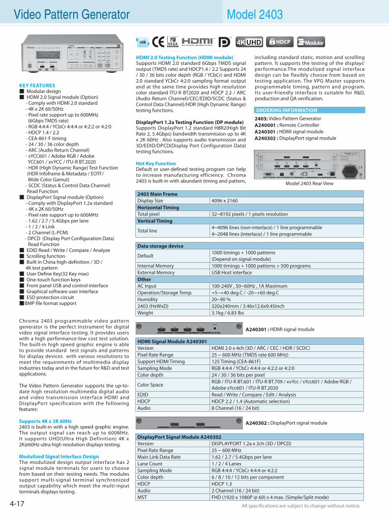
4-17 All specifications are subject to change without notice. All specifications are subject to change without notice.
Video Pattern Generator Model 2403
KEY FEATURES Modular design HDMI 2.0 Signal module (Option) - Comply with HDMI 2.0 standard - 4K x 2K 60/50Hz - Pixel rate support up to 600MHz (6Gbps TMDS rate) - RGB 4:4:4 / YCbCr 4:4:4 or 4:2:2 or 4:2:0 - HDCP 1.4 / 2.2 - CEA-861-F timing - 24 / 30 / 36 color depth - ARC (Audio Return Channel) - sYCC601 / Adobe RGB / Adobe YCC601 / xvYCC / ITU-R BT.2020 - HDR (High Dynamic Range) Test Function (HDR Infoframe & Metadata / EOTF/ Wide Color Gamut) - SCDC (Status & Control Data Channel) Read Function DisplayPort Signal module (Option) - Comply with DisplayPort 1.2a standard - 4K x 2K 60/50Hz - Pixel rate support up to 600MHz - 1.62 / 2.7 / 5.4Gbps per lane - 1 / 2 / 4 Link - 2 Channel (L-PCM) - DPCD (Display Port Configuration Data) Read Function EDID Read / Write / Compare / Analyze Scrolling function Built in China high-definition / 3D / 4K test pattern User Define Key(32 Key max) One-touch function keys Front panel USB and control interface Graphical software user interface ESD protection circuit BMP file format support
Chroma 2403 programmable video pattern generator is the perfect instrument for digital video signal interface testing. It provides users with a high performance-low cost test solution. The built-in high speed graphic engine is able to provide standard test signals and patterns for display devices with various resolutions to meet the requirements of multimedia display industries today and in the future for R&D and test applications.
The Video Pattern Generator supports the up-to-date high resolution multimedia digital audio and video transmission inter face HDMI and DisplayPort specification with the following features: Supports 4K x 2K 60Hz2403 is built-in with a high speed graphic engine. The output signal can reach up to 600MHz. It supports UHD(Ultra High Definition) 4K x 2K@60Hz ultra high resolution displays testing.
Modulized Signal Interface DesignThe modulized design output interface has 2 signal module terminals for users to choose from based on their testing needs. The modules support multi-signal terminal synchronized output capability which meet the multi-input terminals displays testing.
HDMI 2.0 Testing Function (HDMI module)Supports HDMI 2.0 standard 6Gbps TMDS signal output (TMDS rate) and HDCP1.4 / 2.2 Supports 24 / 30 / 36 bits color depth (RGB / YCbCr) and HDMI 2.0 standard YCbCr 4:2:0 sampling format output and at the same time provides high resolution color standard ITU-R BT2020 and HDCP 2.2 / ARC (Audio Return Channel)/CEC/EDID/SCDC (Status & Control Data Channel)/HDR (High Dynamic Range) testing functions.
DisplayPort 1.2a Testing Function (DP module)Supports DisplayPort 1.2 standard HBR2(High Bit Rate 2, 5.4Gbps) bandwidth transmission up to 4K x 2K 60Hz . Also supports audio transmission and 3D/EDID/DPCD(Display Port Configuration Data) testing functions.
Hot Key FunctionDefault or user-defined testing program can help to increase manufacturing efficiency. Chroma 2403 is built-in with abundant timing and pattern,
including standard static, motion and scrolling pattern. It supports the testing of the displays' performance.The modulized signal interface design can be flexibly choose from based on testing application. The VPG Master supports programmable timing, pattern and program. Its user-friendly interface is suitable for R&D, production and QA verification.
2403: Video Pattern GeneratorA240001 : Remote ControllerA240301 : HDMI signal moduleA240302 : DisplayPort signal module
ORDERING INFORMATION
Model 2403 Rear View
4KUHD Modular
2403 Main FrameDisplay Size 4096 x 2160Horizontal TimingTotal pixel 32~8192 pixels / 1 pixels resolutionVertical Timing
Total line4~4096 lines (non-interlace) / 1 line programmable4~2048 lines (interlace) / 1 line programmable
Data storage device
Default1000 timings + 1000 patterns(Depend on signal module)
Internal Memory 1000 timings + 1000 patterns + 500 programsExternal Memory USB Host interfaceOtherAC Input 100-240V , 50~60Hz , 1A MaximumOperation/Storage Temp. +5~+40 deg.C / -20~+60 deg.CHumidity 20~90 %2403 (HxWxD) 320x240mm / 3.46x12.6x9.45inchWeight 3.1kg / 6.83 lbs
A240301 : HDMI signal module
A240302 : DisplayPort signal module
HDMI Signal Module A240301Version HDMI 2.0 x 4ch (3D / ARC / CEC / HDR / SCDC)Pixel Rate Range 25 ~ 600 MHz (TMDS rate 600 MHz)Support HDMI Timing 125 Timing (CEA-861F)Sampling Mode RGB 4:4:4 / YCbCr 4:4:4 or 4:2:2 or 4:2:0Color depth 24 / 30 / 36 bits per pixel
Color Space RGB / ITU-R BT.601 / ITU-R BT.709 / xvYcc / sYcc601 / Adobe RGB / Adobe sYcc601 / ITU-R BT.2020
EDID Read / Write / Compare / Edit / AnalysisHDCP HDCP 2.2 / 1.4 (Automatic selection)Audio 8 Channel (16 / 24 bit)
DisplayPort Signal Module A240302Version DISPLAYPORT 1.2a x 2ch (3D / DPCD)Pixel Rate Range 25 ~ 600 MHzMain Link Data Rate 1.62 / 2.7 / 5.4Gbps per laneLane Count 1 / 2 / 4 LanesSampling Mode RGB 4:4:4 / YCbCr 4:4:4 or 4:2:2Color depth 6 / 8 / 10 / 12 bits per componentHDCP HDCP 1.3Audio 2 Channel (16 / 24 bit)MST FHD (1920 x 1080P @ 60) x 4 max. (Simple/Split mode)
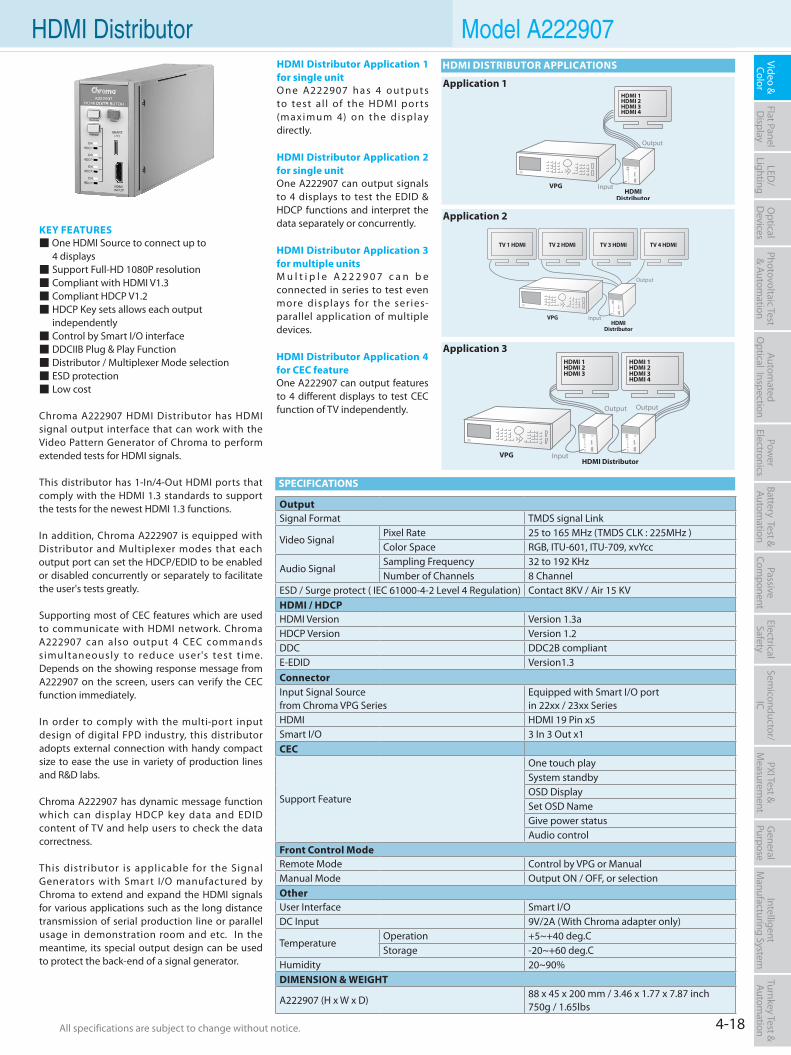
4-18All specifications are subject to change without notice. All specifications are subject to change without notice.
Flat PanelD
isplayPow
er Electronics
Electrical Safety
General
PurposePassive
Component
Semiconductor/
ICBattery Test & Autom
ationAutom
atedO
ptical Inspection Photovoltaic Test
& Automation
PXI Test &
Measurem
ent Video & Color
LED/
LightingO
ptical D
evicesIntelligent
Manufacturing System
Turnkey Test & Autom
ation
KEY FEATURES One HDMI Source to connect up to 4 displays Support Full-HD 1080P resolution Compliant with HDMI V1.3 Compliant HDCP V1.2 HDCP Key sets allows each output independently Control by Smart I/O interface DDCIIB Plug & Play Function Distributor / Multiplexer Mode selection ESD protection Low cost
Chroma A222907 HDMI Distributor has HDMI signal output interface that can work with the Video Pattern Generator of Chroma to perform extended tests for HDMI signals.
This distributor has 1-In/4-Out HDMI ports that comply with the HDMI 1.3 standards to support the tests for the newest HDMI 1.3 functions. In addition, Chroma A222907 is equipped with Distributor and Multiplexer modes that each output port can set the HDCP/EDID to be enabled or disabled concurrently or separately to facilitate the user's tests greatly.
Supporting most of CEC features which are used to communicate with HDMI network. Chroma A222907 can also output 4 CEC commands s imultaneously to reduce user's test t ime. Depends on the showing response message from A222907 on the screen, users can verify the CEC function immediately.
In order to comply with the multi-port input design of digital FPD industry, this distributor adopts external connection with handy compact size to ease the use in variety of production lines and R&D labs.
Chroma A222907 has dynamic message function which can display HDCP key data and EDID content of TV and help users to check the data correctness.
This distributor is applicable for the Signal Generators with Smart I/O manufactured by Chroma to extend and expand the HDMI signals for various applications such as the long distance transmission of serial production line or parallel usage in demonstration room and etc. In the meantime, its special output design can be used to protect the back-end of a signal generator.
HDMI Distributor Application 1 for single unitO n e A222907 h a s 4 o u t p u t s to test al l of the HDMI por ts (maximum 4) on the display directly.
HDMI Distributor Application 2 for single unitOne A222907 can output signals to 4 displays to test the EDID & HDCP functions and interpret the data separately or concurrently.
HDMI Distributor Application 3 for multiple unitsM u l t i p l e A 2 2 2 9 0 7 c a n b e connected in series to test even more displays for the ser ies-parallel application of multiple devices.
HDMI Distributor Application 4 for CEC featureOne A222907 can output features to 4 different displays to test CEC function of TV independently.
SPECIFICATIONS
HDMI Distributor Model A222907
OutputSignal Format TMDS signal Link
Video SignalPixel Rate 25 to 165 MHz (TMDS CLK : 225MHz )Color Space RGB, ITU-601, ITU-709, xvYcc
Audio SignalSampling Frequency 32 to 192 KHzNumber of Channels 8 Channel
ESD / Surge protect ( IEC 61000-4-2 Level 4 Regulation) Contact 8KV / Air 15 KVHDMI / HDCPHDMI Version Version 1.3aHDCP Version Version 1.2DDC DDC2B compliantE-EDID Version1.3ConnectorInput Signal Sourcefrom Chroma VPG Series
Equipped with Smart I/O portin 22xx / 23xx Series
HDMI HDMI 19 Pin x5Smart I/O 3 In 3 Out x1CEC
Support Feature
One touch playSystem standbyOSD DisplaySet OSD NameGive power statusAudio control
Front Control ModeRemote Mode Control by VPG or ManualManual Mode Output ON / OFF, or selectionOtherUser Interface Smart I/ODC Input 9V/2A (With Chroma adapter only)
TemperatureOperation +5~+40 deg.CStorage -20~+60 deg.C
Humidity 20~90%DIMENSION & WEIGHT
A222907 (H x W x D)88 x 45 x 200 mm / 3.46 x 1.77 x 7.87 inch750g / 1.65lbs
HDMI DISTRIBUTOR APPLICATIONS
Application 1
Application 2
Application 3
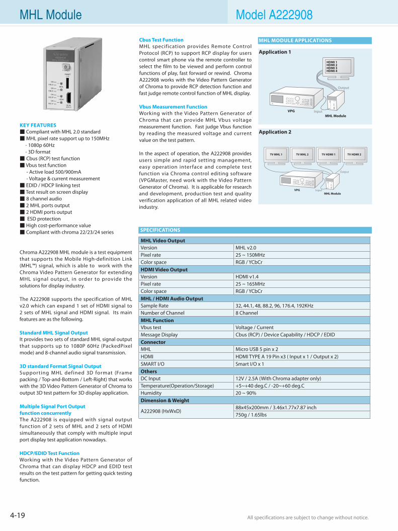
4-19 All specifications are subject to change without notice. All specifications are subject to change without notice.
SPECIFICATIONS
MHL Module Model A222908
MHL MODULE APPLICATIONS
MHL Module
TV MHL 1 TV MHL 2 TV HDMI 2TV HDMI 1
MHL Module
Application 1
Application 2KEY FEATURES Compliant with MHL 2.0 standard MHL pixel rate support up to 150MHz - 1080p 60Hz - 3D format Cbus (RCP) test function Vbus test function - Active load 500/900mA - Voltage & current measurement EDID / HDCP linking test Test result on screen display 8 channel audio 2 MHL ports output 2 HDMI ports output ESD protection High cost-performance value Compliant with chroma 22/23/24 series
Chroma A222908 MHL module is a test equipment that supports the Mobile High-definition Link (MHL™) signal, which is able to work with the Chroma Video Pattern Generator for extending MHL signal output, in order to provide the solutions for display industry.
The A222908 supports the specification of MHL v2.0 which can expand 1 set of HDMI signal to 2 sets of MHL signal and HDMI signal. Its main features are as the following.
Standard MHL Signal OutputIt provides two sets of standard MHL signal output that supports up to 1080P 60Hz (PackedPixel mode) and 8-channel audio signal transmission.
3D standard Format Signal OutputSupporting MHL defined 3D format (Frame packing / Top-and-Bottom / Left-Right) that works with the 3D Video Pattern Generator of Chroma to output 3D test pattern for 3D display application.
Multiple Signal Port Output function concurrentlyThe A222908 is equipped with signal output function of 2 sets of MHL and 2 sets of HDMI simultaneously that comply with multiple input port display test application nowadays.
HDCP/EDID Test FunctionWorking with the Video Pattern Generator of Chroma that can display HDCP and EDID test results on the test pattern for getting quick testing function.
Cbus Test FunctionMHL specification provides Remote Control Protocol (RCP) to support RCP display for users control smart phone via the remote controller to select the film to be viewed and perform control functions of play, fast forward or rewind. Chroma A222908 works with the Video Pattern Generator of Chroma to provide RCP detection function and fast judge remote control function of MHL display.
Vbus Measurement FunctionWorking with the Video Pattern Generator of Chroma that can provide MHL Vbus voltage measurement function. Fast judge Vbus function by reading the measured voltage and current value on the test pattern.
In the aspect of operation, the A222908 provides users simple and rapid setting management, easy operation inter face and complete test function via Chroma control editing software (VPGMaster, need work with the Video Pattern Generator of Chroma). It is applicable for research and development, production test and quality verification application of all MHL related video industry.
MHL Video OutputVersion MHL v2.0 Pixel rate 25 ~ 150MHz Color space RGB / YCbCr HDMI Video Output Version HDMI v1.4 Pixel rate 25 ~ 165MHz Color space RGB / YCbCr MHL / HDMI Audio OutputSample Rate 32, 44.1, 48, 88.2, 96, 176.4, 192KHz Number of Channel 8 Channel MHL FunctionVbus test Voltage / Current Message Display Cbus (RCP) / Device Capability / HDCP / EDID ConnectorMHL Micro USB 5 pin x 2 HDMI HDMI TYPE A 19 Pin x3 ( Input x 1 / Output x 2) SMART I/O Smart I/O x 1 OthersDC Input 12V / 2.5A (With Chroma adapter only) Temperature(Operation/Storage) +5~+40 deg.C / -20~+60 deg.C Humidity 20 ~ 90% Dimension & Weight
A222908 (HxWxD) 88x45x200mm / 3.46x1.77x7.87 inch 750g / 1.65lbs
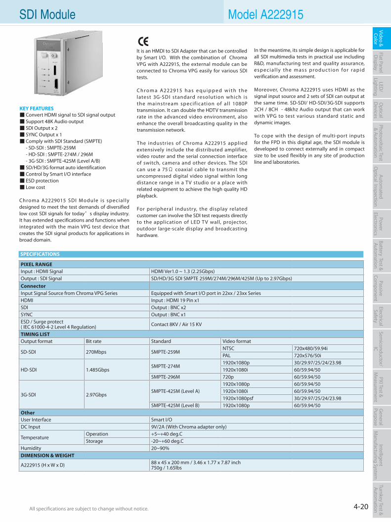
4-20All specifications are subject to change without notice. All specifications are subject to change without notice.
Flat PanelD
isplayPow
er Electronics
Electrical Safety
General
PurposePassive
Component
Semiconductor/
ICBattery Test & Autom
ationAutom
atedO
ptical Inspection Photovoltaic Test
& Automation
PXI Test &
Measurem
ent Video & Color
LED/
LightingO
ptical D
evicesIntelligent
Manufacturing System
Turnkey Test & Autom
ation SDI Module Model A222915
KEY FEATURES Convert HDMI signal to SDI signal output Support 48K Audio output SDI Output x 2 SYNC Output x 1 Comply with SDI Standard (SMPTE) - SD-SDI : SMPTE-259M - HD-SDI : SMPTE-274M / 296M - 3G-SDI : SMPTE-425M (Level A/B) SD/HD/3G format auto identification Control by Smart I/O interface ESD protection Low cost
Chroma A2229015 SDI Module is special ly designed to meet the test demands of diversified low cost SDI signals for today’s display industry. It has extended specifications and functions when integrated with the main VPG test device that creates the SDI signal products for applications in broad domain.
It is an HMDI to SDI Adapter that can be controlled by Smart I/O. With the combination of Chroma VPG with A222915, the external module can be connected to Chroma VPG easily for various SDI tests.
C h r o m a A222915 h a s e q u i p p e d w i t h t h e latest 3G-SDI standard resolution which is the mainstream speci f icat ion of a l l 1080P transmission. It can double the HDTV transmission rate in the advanced video environment, also enhance the overall broadcasting quality in the transmission network.
The industries of Chroma A222915 applied extensively include the distributed amplifier, video router and the serial connection interface of switch, camera and other devices. The SDI can use a 75Ω coaxial cable to transmit the uncompressed digital video signal within long distance range in a TV studio or a place with related equipment to achieve the high quality HD playback.
For peripheral industry, the display related customer can involve the SDI test requests directly to the application of LED T V wall, projector, outdoor large-scale display and broadcasting hardware.
In the meantime, its simple design is applicable for all SDI multimedia tests in practical use including R&D, manufacturing test and quality assurance, e s p e c i a l l y t h e m a s s p ro d u c t i o n fo r ra p i d verification and assessment.
Moreover, Chroma A222915 uses HDMI as the signal input source and 2 sets of SDI can output at the same time. SD-SDI/ HD-SDI/3G-SDI supports 2CH / 8CH - 48khz Audio output that can work with VPG to test various standard static and dynamic images.
To cope with the design of multi-port inputs for the FPD in this digital age, the SDI module is developed to connect externally and in compact size to be used flexibly in any site of production line and laboratories.
PIXEL RANGEInput : HDMI Signal HDMI Ver1.0 ~ 1.3 (2.25Gbps)Output : SDI Signal SD/HD/3G SDI SMPTE 259M/274M/296M/425M (Up to 2.97Gbps)ConnectorInput Signal Source from Chroma VPG Series Equipped with Smart I/O port in 22xx / 23xx SeriesHDMI Input : HDMI 19 Pin x1SDI Output : BNC x2SYNC Output : BNC x1ESD / Surge protect ( IEC 61000-4-2 Level 4 Regulation) Contact 8KV / Air 15 KV
TIMING LISTOutput format Bit rate Standard Video format
SD-SDI 270Mbps SMPTE-259MNTSC 720x480/59.94i PAL 720x576/50i
HD-SDI 1.485GbpsSMPTE-274M
1920x1080p 30/29.97/25/24/23.981920x1080i 60/59.94/50
SMPTE-296M 720p 60/59.94/50
3G-SDI 2.97GbpsSMPTE-425M (Level A)
1920x1080p 60/59.94/501920x1080i 60/59.94/501920x1080psf 30/29.97/25/24/23.98
SMPTE-425M (Level B) 1920x1080p 60/59.94/50OtherUser Interface Smart I/ODC Input 9V/2A (With Chroma adapter only)
TemperatureOperation +5~+40 deg.CStorage -20~+60 deg.C
Humidity 20~90%DIMENSION & WEIGHT
A222915 (H x W x D) 88 x 45 x 200 mm / 3.46 x 1.77 x 7.87 inch750g / 1.65lbs
SPECIFICATIONS
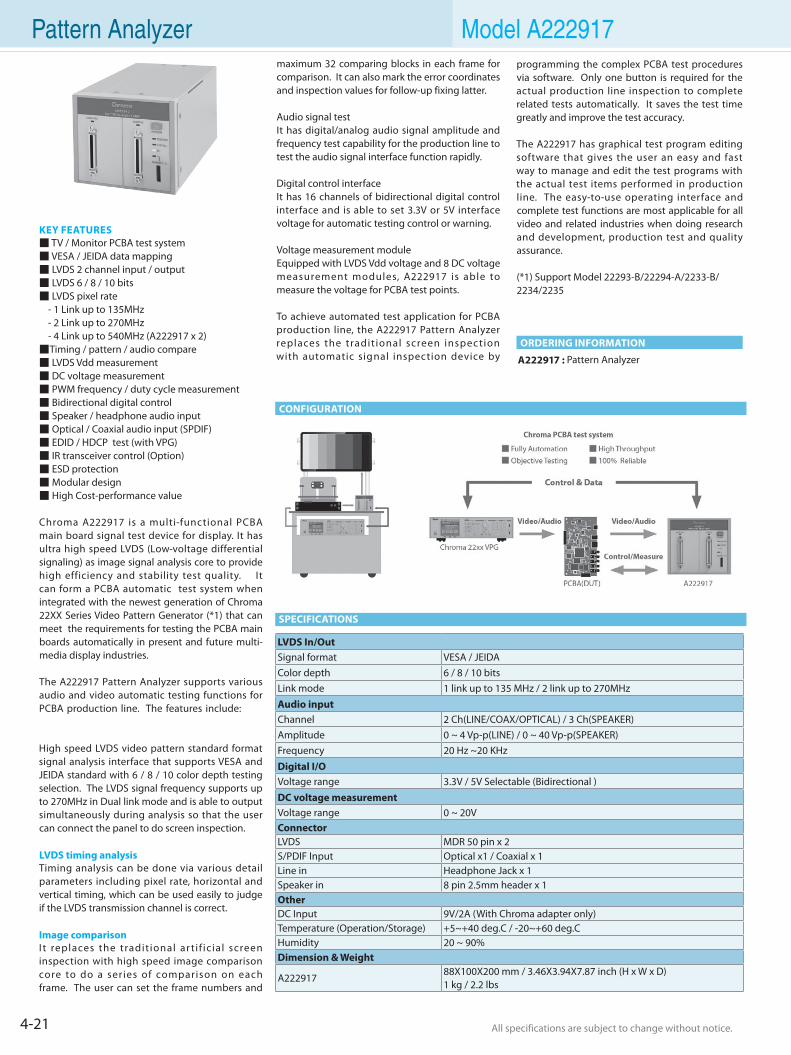
4-21 All specifications are subject to change without notice. All specifications are subject to change without notice.
Pattern Analyzer Model A222917
A222917 : Pattern Analyzer
ORDERING INFORMATION
CONFIGURATION
KEY FEATURES TV / Monitor PCBA test system VESA / JEIDA data mapping LVDS 2 channel input / output LVDS 6 / 8 / 10 bits LVDS pixel rate - 1 Link up to 135MHz - 2 Link up to 270MHz - 4 Link up to 540MHz (A222917 x 2)Timing / pattern / audio compare LVDS Vdd measurement DC voltage measurement PWM frequency / duty cycle measurement Bidirectional digital control Speaker / headphone audio input Optical / Coaxial audio input (SPDIF) EDID / HDCP test (with VPG) IR transceiver control (Option) ESD protection Modular design High Cost-performance value
Chroma A222917 is a multi-functional PCBA main board signal test device for display. It has ultra high speed LVDS (Low-voltage differential signaling) as image signal analysis core to provide high efficiency and stability test quality. It can form a PCBA automatic test system when integrated with the newest generation of Chroma 22XX Series Video Pattern Generator (*1) that can meet the requirements for testing the PCBA main boards automatically in present and future multi-media display industries.
The A222917 Pattern Analyzer supports various audio and video automatic testing functions for PCBA production line. The features include:
High speed LVDS video pattern standard format signal analysis interface that supports VESA and JEIDA standard with 6 / 8 / 10 color depth testing selection. The LVDS signal frequency supports up to 270MHz in Dual link mode and is able to output simultaneously during analysis so that the user can connect the panel to do screen inspection.
LVDS timing analysisTiming analysis can be done via various detail parameters including pixel rate, horizontal and vertical timing, which can be used easily to judge if the LVDS transmission channel is correct.
Image comparisonI t replaces the tradit ional ar t i f ic ial screen inspection with high speed image comparison core to do a series of comparison on each frame. The user can set the frame numbers and
maximum 32 comparing blocks in each frame for comparison. It can also mark the error coordinates and inspection values for follow-up fixing latter.
Audio signal testIt has digital/analog audio signal amplitude and frequency test capability for the production line to test the audio signal interface function rapidly.
Digital control interfaceIt has 16 channels of bidirectional digital control interface and is able to set 3.3V or 5V interface voltage for automatic testing control or warning.
Voltage measurement moduleEquipped with LVDS Vdd voltage and 8 DC voltage measurement modules, A222917 is able to measure the voltage for PCBA test points.
To achieve automated test application for PCBA production line, the A222917 Pattern Analyzer replaces the tradit ional screen inspection with automatic signal inspection device by
SPECIFICATIONS
programming the complex PCBA test procedures via software. Only one button is required for the actual production line inspection to complete related tests automatically. It saves the test time greatly and improve the test accuracy.
The A222917 has graphical test program editing software that gives the user an easy and fast way to manage and edit the test programs with the actual test items performed in production line. The easy-to-use operating interface and complete test functions are most applicable for all video and related industries when doing research and development, production test and quality assurance.
(*1) Support Model 22293-B/22294-A/2233-B/ 2234/2235
LVDS In/OutSignal format VESA / JEIDA Color depth 6 / 8 / 10 bits Link mode 1 link up to 135 MHz / 2 link up to 270MHz Audio inputChannel 2 Ch(LINE/COAX/OPTICAL) / 3 Ch(SPEAKER) Amplitude 0 ~ 4 Vp-p(LINE) / 0 ~ 40 Vp-p(SPEAKER) Frequency 20 Hz ~20 KHz Digital I/OVoltage range 3.3V / 5V Selectable (Bidirectional ) DC voltage measurementVoltage range 0 ~ 20V ConnectorLVDS MDR 50 pin x 2 S/PDIF Input Optical x1 / Coaxial x 1 Line in Headphone Jack x 1 Speaker in 8 pin 2.5mm header x 1 Other DC Input 9V/2A (With Chroma adapter only) Temperature (Operation/Storage) +5~+40 deg.C / -20~+60 deg.C Humidity 20 ~ 90% Dimension & Weight
A22291788X100X200 mm / 3.46X3.94X7.87 inch (H x W x D)1 kg / 2.2 lbs
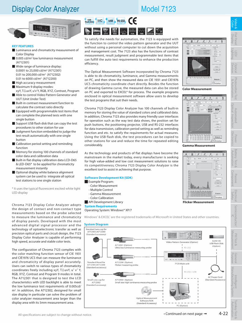
4-22All specifications are subject to change without notice. All specifications are subject to change without notice.
Flat PanelD
isplayPow
er Electronics
Electrical Safety
General
PurposePassive
Component
Semiconductor/
ICBattery Test & Autom
ationAutom
atedO
ptical Inspection Photovoltaic Test
& Automation
PXI Test &
Measurem
ent Video & Color
LED/
LightingO
ptical D
evicesIntelligent
Manufacturing System
Turnkey Test & Autom
ation Display Color Analyzer Model 7123
To satisfy the needs for automation, the 7123 is equipped with the function to control the video pattern generator and the UUT without using a personal computer to cut down the acquisition and management cost. The 7123 also has the functions of contrast measurement, result judgment and programmable test items that can fulfill the auto test requirements to enhance the production efficiency.
The Optical Measurement Software incorporated by Chroma 7123 is able to do chromaticity, luminance, and Gamma measurements on PC, and then show the measured data on CIE 1931 and CIE1976 UCS chromaticity coordinate chart directly. Besides the function of drawing Gamma curve, the measured data can also be stored on PC and exported to EXCEL® for process. The example programs enclosed in optical measurement software allow users to develop the test programs that suit their needs.
Chroma 7123 Display Color Analyzer has 100 channels of built-in memory for storing the value of standard colors and calibrated data. In addition, Chroma 7123 also provides many friendly user interfaces for operation such as the way test data shows, the position set for push buttons, the positioning projector, USB and RS-232 interfaces for data transmission, calibration period setting as well as reminding function and etc. to satisfy the requirements for actual measures. Using the USB flash disk, the test procedures can be copied to other stations for use and reduce the time for repeated editing considerably.
As the technology and products of flat displays have become the mainstream in the market today, every manufacturer is seeking for high value-added and low cost measurement solutions to raise its competitiveness; Chroma 7123 Display Color Analyzer is the excellent tool to assist in achieving that purpose.
Software Development Kit (SDK) Example Program: - Color Measurement - Multiple Control - Gamma Measurement - Color Calibration API Development LibrarySystem RequirementsOperating System: Windows® XP/7
KEY FEATURES Luminance and chromaticity measurement of Color Display 0.005 cd/m2 low luminance measurement (A712301) Wide range of luminance display: 0.0001 to 25,000 cd/m2 (A712301) 0.01 to 200,000 cd/m2 (A712302) 0.01 to 6000 cd/m2 (A712200) High accuracy measurement Maximum 9 display modes: xyY, TΔuvY, u'v'Y, RGB, XYZ, Contrast, Program Able to control Video Pattern Generator and UUT (Unit Under Test) Built-in contrast measurement function to calculate the contrast ratio directly Equipped with programmable test items that can complete the planned tests with one single button Support USB flash disk that can copy the test procedures to other station for use Judgment function embedded to judge the test result automatically with one single button Calibration period setting and reminding function Memory for storing 100 channels of standard color data and calibration data Built-in flat display calibration data LCD-D65 & LED-D65* to be applied for chromaticity measurement instantly Optional display white balance alignment system can be used to integrate all optical test stations to one single station
* It uses the typical fluorescent excited white light LED display
Chroma 7123 Display Color Analyzer adopts the design of contact and non-contact type measurements based on the probe selected to measure the luminance and chromaticity of display panels. Developed with the most advanced digital s ignal processor and the technology of optoelectronic transfer as well as precision optical parts and circuit design, the 7123 Display Color Analyzer is capable of performing high speed, accurate and stable color tests.
The configuration of Chroma 7123 complies with the color matching function sensor of CIE 1931 and CIE1976 UCS that can measure the luminance and chromaticity of display panel accurately. Users can switch to various types of chromaticity coordinates freely including xyY, TΔuvY, u’v’Y, RGB, XYZ, Contrast and Program 9 modes in total. The A712301 that is designed to test the LCD characteristics with LED backlight is able to meet the low luminance test requirements of 0.005cd/m2. In addition, the A712302, designed for small size display in particular can solve the problem of color analyzer measurement area larger than the display area with its 5mm measurement area.
Color Measurement
USB Flash Disk
Gamma Measurement
Flicker Measurement
System Diagram
Windows® & EXCEL® are the registered trademarks of Microsoft in United States and other countries.
• Continued on next page
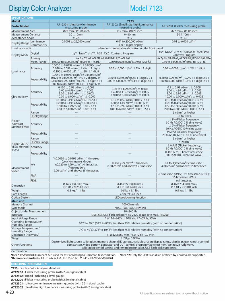
4-23 All specifications are subject to change without notice. All specifications are subject to change without notice.
Display Color Analyzer Model 7123
7123 : Display Color Analyzer Main UnitA712200 : Flicker measuring probe (with 2.5m signal cable)A712102 : Tripod (including a level gauge)A712200 : Flicker measuring probe (with 2.5m signal cable)A712301 : Ultra-Low luminance measuring probe (with 2.5m signal cable)A712302 : Small size high luminance measuring probe (with 2.5m signal cable)
ORDERING INFORMATION
SPECIFICATIONSModel 7123
Probe Model A712301 (Ultra-Low luminance measuring probe)
A712302 (Small size high Luminance measuring probe) A712200 (Flicker measuring probe)
Measurement Area Ø27 mm / Ø1.06 inch Ø5 mm / Ø0.20 inch Ø27 mm / Ø1.06 inchMeasurement Distance 30±10mm 0~10mm 30±10mmAcceptance Angle ± 2.5˚ ± 5˚ ± 2.5˚
Display Range Luminance 0.0001 to 25,000 cd/m2 0.01 to 200,000 cd/m2 0.01 to 6,000 cd/m2
Chromaticity 4 or 3 digits displayLuminance unit cd/m2 or fL, selectable via button on the front panel
Display Mode Digital xyY ; T∆uvY; u' v' Y ; RGB ; XYZ ; Contrast; Program xyY; T∆uvY; u' v' Y; RGB; XYZ; FMA; FLVL; Contrast; Program
Analog ∆x ∆y ∆Y; ∆R ∆G ∆B; ∆R G/R B/R; R/G ∆G B/G ∆x ∆y ∆Y; ∆R ∆G ∆B; ∆R G/R B/R; R/G ∆G B/G;FMA
Luminance*1
Meas. Range 0.0050 to 6,000cd/m2 (0.001 to 1751fL) 0.30 to 6,000 cd/m2 (0.09 to 1751 fL) 0.10 to 6,000 cd/m2 (0.03 to 1751 fL)
Accuracy0.0050 to 0.0199 cd/m2 :±0.0005cd/m2
0.020 to 0.099 cd/m2 :±4% ±2 digits0.100 to 6,000 cd/m2 :±2% ±1 digit
0.30 to 6,000 cd/m2 :±2%±1 digit 0.10 to 6,000 cd/m2 : ±2%±1 digit
Repeatability0.0050 to 0.0199 cd/m2 :±0.0003cd/m2
0.020 to 0.099 cd/m2 : 1% + 2 digits(2σ)0.100 to 0.999 cd/m2 : 0.2% + 1 digit(2σ)1.00 to 6,000 cd/m2 : 0.1% + 1 digit (2σ)
0.30 to 2.99cd/m2 : 0.2% +1 digit(2σ)3.00 to 6,000 cd/m2:0.1%+1 digit(2σ)
0.10 to 0.99 cd/m2 : 0.2% + 1 digit (2σ)1.00 to 6,000 cd/m2: 0.1% + 1 digit (2σ)
Chromaticity*1
Accuracy0.100 to 2.99 cd/m2 : ±0.0083.00 to 4.99 cd/m2 : ±0.0055.00 to 9.99 cd/m2 : ± 0.003
10.00 to 6,000 cd/m2 : ± 0.002
0.30 to 14.99 cd/m2 : ± 0.008 15.00 to 119.9 cd/m2 : ± 0.005120.0 to 6,000 cd/m2 : ± 0.003
0.1 to 2.99 cd/m2 : ± 0.008 3.00 to 4.99 cd/m2 : ± 0.0055.00 to 9.99 cd/m2 : ± 0.003
10.00 to 6,000 cd/m2 : ± 0.002
Repeatability0.100 to 0.199 cd/m2 : 0.015(2σ)0.200 to 0.499 cd/m2 : 0.008(2σ)0.500 to 1.99 cd/m2 : 0.003(2σ)2.00 to 6,000 cd/m2 : 0.001(2σ)
0.30 to 0.59 cd/m2 : 0.015 (2σ)0.60 to 1.49 cd/m2 : 0.008 (2σ)1.50 to 7.99 cd/m2 : 0.003 (2σ)
8.00 to 6,000 cd/m2 : 0.001 (2σ)
0.10 to 0.19 cd/m2 : 0.015 (2σ)0.20 to 0.49 cd/m2 : 0.008 (2σ)0.50 to 1.99 cd/m2 : 0.003 (2σ)
2.00 to 6,000 cd/m2 : 0.001 (2σ)
Flicker -Contrast Method(FMA)
Range --- --- 5 cd/m2 or higherDisplay Range --- --- 0.0 to 100%
Accuracy --- ---±1% (Flicker frequency:
30 Hz AC/DC10 % sine wave)±2% (Flicker frequency:
60 Hz AC/DC 10 % sine wave)
Repeatability --- --- 1% (2σ) (Flicker frequency:20 to 65 Hz AC/DC 10 % sine wave)
Flicker -JEITA/VESA Method(FLVL)
Range --- --- 5 cd/m2 or higherDisplay Range --- --- 6-240Hz
Accuracy --- --- ±0.5dB (Flicker frequency:30 Hz AC/DC10 % sine wave)
Repeatability --- --- 0.3dB (2σ) (Flicker frequency:30 Hz AC/DC 10 % sine wave)
Measurement Speed
xyY
Y:0.0050 to 0.0199 cd/m2 : 1 time/sec(Low luminance Mode)
Y:0.020 to 1.99 cd/m2 : 4 times/sec. (Auto mode) ;
2.00 cd/m2 and above: 15 times/sec.
0.3 to 7.99 cd/m2 :1 time/sec. 8.00 cd/m2 and above:15 times/sec.
0.1 to 3.99 cd/m2 : 5 times/sec. ;4.00 cd/m2 and above: 15 times/sec.
FMA --- --- 6 times/sec. (UNIV) ; 20 times/sec.(NTSC); 16 times/sec. (PAL)
FLVL --- --- 0.5 time/sec.
Dimension Ø 46 x 234.9(D) mm / Ø 1.81 x 9.25(D) inch
Ø 46 x 221.9(D) mm / Ø 1.81 x 8.74 (D) inch
Ø 46 x 234.9(D) mm / Ø 1.81 x 9.25(D) inch
Weight 0.5 kg / 1.1 lbs 0.5 kg / 1.1 lbs 0.5 kg / 1.1 lbsCord Length 2.5m / 98.43 inchOptical System LED positioning functionMain unitMemory Channel 100 ChannelsSync Mode NTSC, PAL, EXT, UNIV, INTObject Under Measurement 10~240 HzInterface USB(2.0), USB flash disk port, RS-232C (Baud rate max. 115200)Input Voltage Range 1Ø 110~240V ±10% VLN, 47~63Hz, 50VAOperating Temperature/Humidity Range 10˚C to 30˚C (50˚F to 86˚F); less than 75% relative humidity (with no condensation)
Storage Temperature /Humidity Range 0˚C to 40˚C (32˚F to 104˚F); less than 75% relative humidity (with no condensation)
Dimension (H x W x D) 115x320x260 mm / 4.5x12.6x10.2 inchWeight 2.7 Kg / 5.95lbs
Other FunctionsCustomized light source calibration, memory channel ID storage, variable analog display range, display pause, remote control,
comparison, video pattern generator and UUT control, programmable test item, test result judgment, calibration period setting and reminding function, USB flash disk supported. *2
Certification CENote *1: Standard illuminant A is used for test according to Chroma's test condition. Note *2: Only the USB flash disks certified by Chroma are supported.*Reference standards: IEC 61747-6, EIAJ ED-2522, ASTM E455-03, VESA Standard
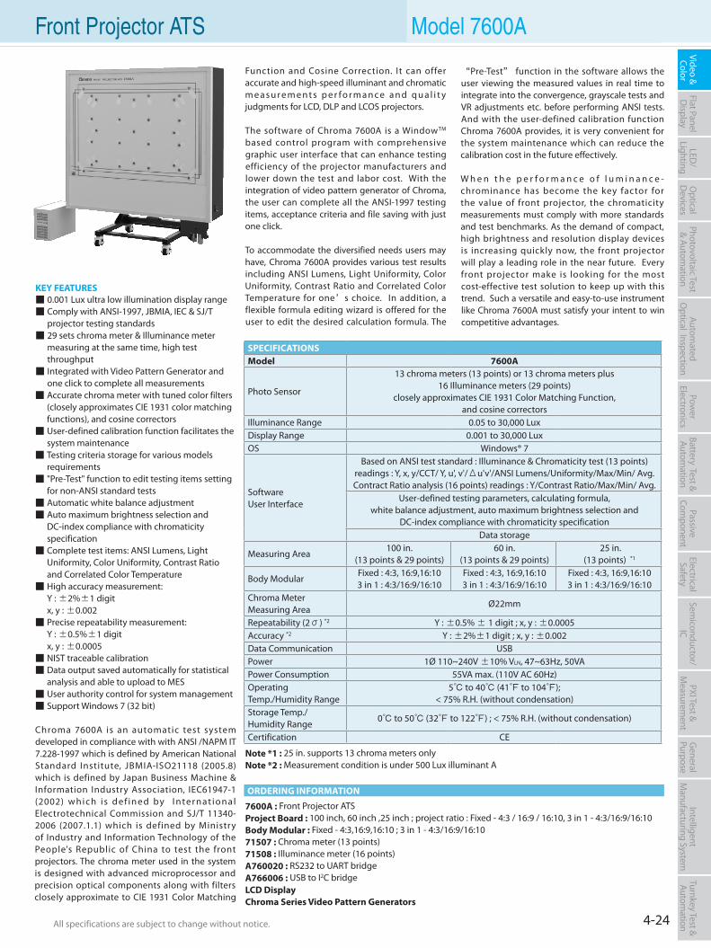
4-24All specifications are subject to change without notice. All specifications are subject to change without notice.
Flat PanelD
isplayPow
er Electronics
Electrical Safety
General
PurposePassive
Component
Semiconductor/
ICBattery Test & Autom
ationAutom
atedO
ptical Inspection Photovoltaic Test
& Automation
PXI Test &
Measurem
ent Video & Color
LED/
LightingO
ptical D
evicesIntelligent
Manufacturing System
Turnkey Test & Autom
ation Front Projector ATS Model 7600A
7600A : Front Projector ATSProject Board : 100 inch, 60 inch ,25 inch ; project ratio : Fixed - 4:3 / 16:9 / 16:10, 3 in 1 - 4:3/16:9/16:10Body Modular : Fixed - 4:3,16:9,16:10 ; 3 in 1 - 4:3/16:9/16:1071507 : Chroma meter (13 points)71508 : Illuminance meter (16 points)A760020 : RS232 to UART bridgeA766006 : USB to I2C bridgeLCD DisplayChroma Series Video Pattern Generators
ORDERING INFORMATION
Function and Cosine Correction. It can offer accurate and high-speed illuminant and chromatic m e a s u r e m e n t s p e r fo r m a n c e a n d q u a l i t y judgments for LCD, DLP and LCOS projectors.
The software of Chroma 7600A is a WindowTM
based control program with comprehensive graphic user interface that can enhance testing efficiency of the projector manufacturers and lower down the test and labor cost. With the integration of video pattern generator of Chroma, the user can complete all the ANSI-1997 testing items, acceptance criteria and file saving with just one click.
To accommodate the diversified needs users may have, Chroma 7600A provides various test results including ANSI Lumens, Light Uniformity, Color Uniformity, Contrast Ratio and Correlated Color Temperature for one’s choice. In addition, a flexible formula editing wizard is offered for the user to edit the desired calculation formula. The
KEY FEATURES 0.001 Lux ultra low illumination display range Comply with ANSI-1997, JBMIA, IEC & SJ/T projector testing standards 29 sets chroma meter & Illuminance meter measuring at the same time, high test throughput Integrated with Video Pattern Generator and one click to complete all measurements Accurate chroma meter with tuned color filters (closely approximates CIE 1931 color matching functions), and cosine correctors User-defined calibration function facilitates the system maintenance Testing criteria storage for various models requirements "Pre-Test" function to edit testing items setting for non-ANSI standard tests Automatic white balance adjustment Auto maximum brightness selection and DC-index compliance with chromaticity specification Complete test items: ANSI Lumens, Light Uniformity, Color Uniformity, Contrast Ratio and Correlated Color Temperature High accuracy measurement: Y : ±2%±1 digit x, y : ±0.002 Precise repeatability measurement: Y : ±0.5%±1 digit x, y : ±0.0005 NIST traceable calibration Data output saved automatically for statistical analysis and able to upload to MES User authority control for system management Support Windows 7 (32 bit)
Chroma 7600A is an automatic test system developed in compliance with with ANSI /NAPM IT 7.228-1997 which is defined by American National Standard Institute, JBMIA-ISO21118 (2005.8) which is defined by Japan Business Machine & Information Industry Association, IEC61947-1 (2002) which i s def ined by I nter nat ional Electrotechnical Commission and SJ/T 11340-2006 (2007.1.1) which is defined by Ministry of Industry and Information Technology of the People's Republic of China to test the front projectors. The chroma meter used in the system is designed with advanced microprocessor and precision optical components along with filters closely approximate to CIE 1931 Color Matching
SPECIFICATIONSModel 7600A
Photo Sensor
13 chroma meters (13 points) or 13 chroma meters plus16 Illuminance meters (29 points)
closely approximates CIE 1931 Color Matching Function, and cosine correctors
Illuminance Range 0.05 to 30,000 LuxDisplay Range 0.001 to 30,000 LuxOS Windows® 7
SoftwareUser Interface
Based on ANSI test standard : Illuminance & Chromaticity test (13 points) readings : Y, x, y/CCT/ Y, u', v'/Δu'v'/ANSI Lumens/Uniformity/Max/Min/ Avg.Contract Ratio analysis (16 points) readings : Y/Contrast Ratio/Max/Min/ Avg.
User-defined testing parameters, calculating formula, white balance adjustment, auto maximum brightness selection and
DC-index compliance with chromaticity specificationData storage
Measuring Area100 in.
(13 points & 29 points)60 in.
(13 points & 29 points) 25 in.
(13 points) *1
Body ModularFixed : 4:3, 16:9,16:103 in 1 : 4:3/16:9/16:10
Fixed : 4:3, 16:9,16:103 in 1 : 4:3/16:9/16:10
Fixed : 4:3, 16:9,16:103 in 1 : 4:3/16:9/16:10
Chroma Meter Measuring Area
Ø22mm
Repeatability (2σ) *2 Y : ±0.5% ± 1 digit ; x, y : ±0.0005Accuracy *2 Y : ±2%±1 digit ; x, y : ±0.002Data Communication USBPower 1Ø 110~240V ±10% VLN, 47~63Hz, 50VAPower Consumption 55VA max. (110V AC 60Hz)Operating Temp./Humidity Range
5 to 40 (41 to 104); < 75% R.H. (without condensation)
Storage Temp./Humidity Range
0 to 50 (32 to 122) ; < 75% R.H. (without condensation)
Certification CE
“Pre-Test” function in the software allows the user viewing the measured values in real time to integrate into the convergence, grayscale tests and VR adjustments etc. before performing ANSI tests. And with the user-defined calibration function Chroma 7600A provides, it is very convenient for the system maintenance which can reduce the calibration cost in the future effectively.
W h e n t h e p e r f o r m a n c e o f l u m i n a n c e - chrominance has become the key factor for the value of front projector, the chromaticity measurements must comply with more standards and test benchmarks. As the demand of compact, high brightness and resolution display devices is increasing quickly now, the front projector will play a leading role in the near future. Every front projector make is looking for the most cost-effective test solution to keep up with this trend. Such a versatile and easy-to-use instrument like Chroma 7600A must satisfy your intent to win competitive advantages.
Note *1 : 25 in. supports 13 chroma meters onlyNote *2 : Measurement condition is under 500 Lux illuminant A
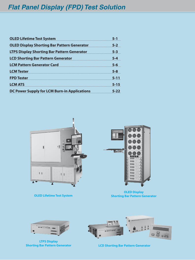
Flat Panel Display (FPD) Test Solution
OLED Lifetime Test SystemOLED Display
Shorting Bar Pattern Generator
LCD Shorting Bar Pattern GeneratorLTPS Display
Shorting Bar Pattern Generator
OLED Lifetime Test System 5-1
OLED Display Shorting Bar Pattern Generator 5-2
LTPS Display Shorting Bar Pattern Generator 5-3
LCD Shorting Bar Pattern Generator 5-4
LCM Pattern Generator Card 5-6
LCM Tester 5-8
FPD Tester 5-11
LCM ATS 5-15
DC Power Supply for LCM Burn-in Applications 5-22
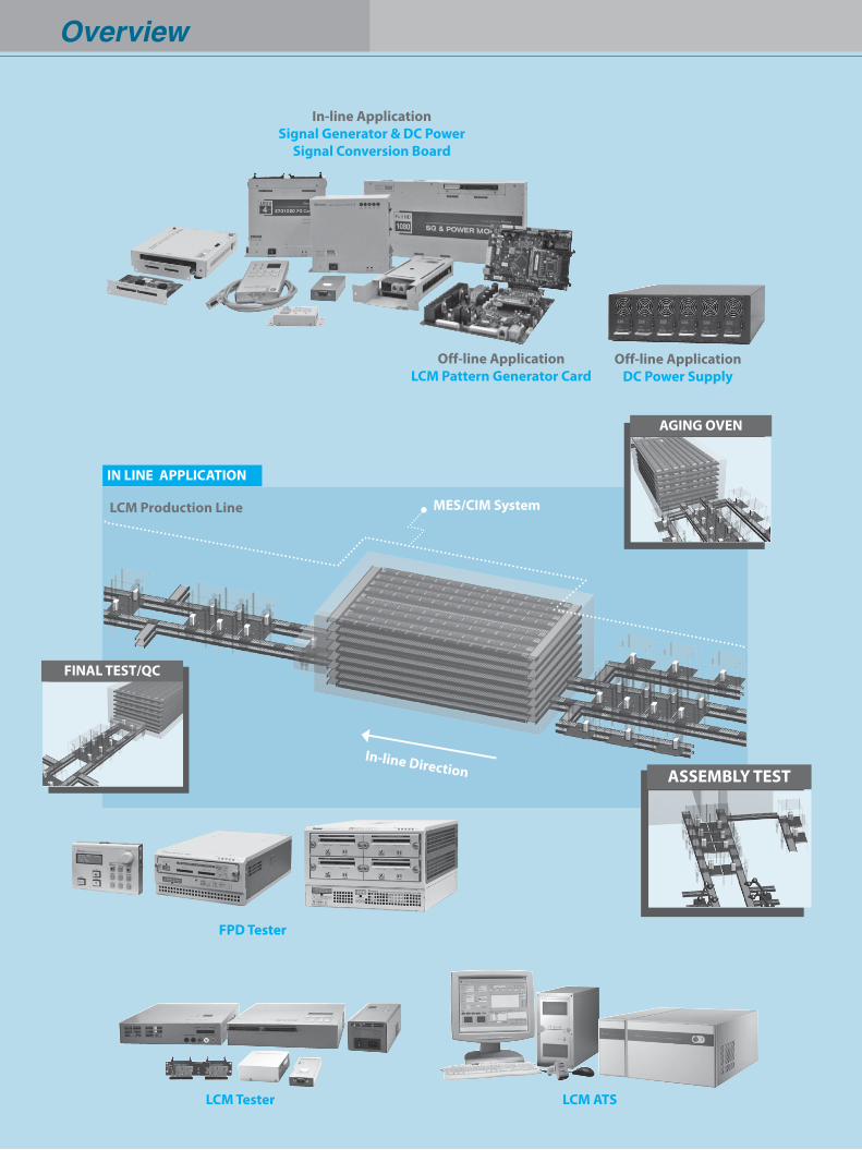
Overview
IN LINE APPLICATION
AGING OVEN
ASSEMBLY TEST
FINAL TEST/QC
LCM Tester
FPD Tester
LCM ATS
Off-line ApplicationDC Power Supply
Off-line ApplicationLCM Pattern Generator Card
In-line ApplicationSignal Generator & DC Power
Signal Conversion Board
LCM Production Line MES/CIM System
In-line Direction
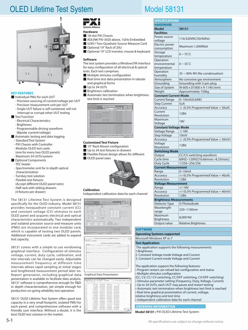
5-1 All specifications are subject to change without notice. All specifications are subject to change without notice.
OLED Lifetime Test System Model 58131
KEY FEATURES Individual PMU for each UUT - Precision sourcing of current/voltage per UUT - Precision measurement unit per UUT - Single UUT failure is self contained, will not
interrupt or corrupt other UUT testing Test Function - Electrical Characteristics - Brightness - Programmable driving waveform (Bipolar current/voltage) Automatic testing and data logging - Standard Test System - PXI Chassis with Controller - Modular OLED test cards (one for every two OLED panels) - Maximum 34 UUTs/system Optional Components - TEC heater - Spectrometer unit for in depth optical
characterization - Turnkey test solution - Flexible test fixtures (Accept different OLED panel sizes) - Half rack with sliding drawers (4 fixtures per drawer)
The 58131 Lifetime Test System is designed specifically for the OLED industry. Model 58131 provides twoquadrant constant current (CC) and constant voltage (CV) stimulus to each OLED panel and acquires electrical and optical characteristics automatically. Two independent and isolated precision source-and-measure units (PMU) are incorporated in one modular card, which is capable of testing two OLED panels. Additional instrument cards are added to expand test capacity.
58131 comes with a simple to use windowing graphical interface. Configuration of stimulus voltage, current, duty cycle, calibration, and test intervals can be changed easily. Adjustable measurement f requenc y at di f ferent t ime intervals allows rapid sampling at initial stages and lengthened measurement period later on. Report generation, including graphical data presentation is available to facilitate data analysis. 58131 software is comprehensive enough for R&D in depth characterization, yet simple enough for production on-going reliability test operation.
58131 OLED Lifetime Test System offers good test capacity in a very small footprint, isolated PMU for each panel, and comprehensive software with a friendly user interface. Without a doubt, it is the best OLED test solution in the market.
Systems Alliance
Hardware 18-slot PXI Chassis ADLINK PXI-3920 above, 1GHz Embedded 52951 Two-Quadrant Source-Measure Card Optional 19" Rack of 20U Optional 19" LCD monitor, mouse & keyboard
SoftwareThe test system provides a WindowsTM interface for easy configuration of all electrical & optical tests. Each test comprises: Multiple stimulus configuration Real time test data presentation in tabular and graphical forms Up to 34 UUTs Brightness calibration Automatic test termination when brightness test limit is reached
Customized Test Fixture 19" Rack Mount configuration Up to 34 test fixtures in drawers Flexible fixture design allows for different OLED panel sizes
CalibrationIndependent calibration data for each channel
SPECIFICATIONSHARDWAREModel 58131FacilitiesPower source voltage 110/220VAC(50/60Hz)
Electric power consumption Maximum 1,000Watt
Storage temperature 0 ~ 75
Operation environmentaltemperature
0 ~ 35
Operation humidity 35 ~ 90% RH (No condensation)
Atmosphere No corrosive gas environmentGrounding Grounding with 3-pin-plugSize of System W 600 x D1000 x H 1140 (mm)Weight Approximately 150kgConstant Current ModeCurrent Range 0~10mA(0.64W)Step Current 5uAAccuracy ± (0.5% Programmed Value + 30uA)Current Resolution 12Bit
Maximum Voltage 18V
Constant Voltage ModeVoltage Range ±18V Step Voltage 10mVAccuracy ± (0.5% Programmed Value + 30mV)Voltage Resolution 12Bit
Switching ModeOutput CC/CV switching waveformCycle time 60HZ~120HZ(16.66msec~8.33msec)Duty Cycle 1/256~256/256Current MeasurementRange 0~10mAAccuracy +/-(0.5% Programmed Value + 40uA)Resolution 12BitVoltage MeasurementRange +/-18VAccuracy +/-(0.5% Programmed Value + 40mV)Resolution 12BitBrightness MeasurementsDetector Type Si PhotodiodeWavelength range 320~1100nm
Maximum Brightness 8,000 Nit
Output value Relative Brightness
SOFTWAREOperating Systems supportedMicrosoft Windows XP or 7Test Application The application supports the following measurements:1.Brightness2. Constant Voltage mode Voltage and Current3. Constant Current mode Voltage and Current
The application support the following features:• Program restart can reload last configuration and status• Multiple stimulus configuration (CC, CV, CC/-CV switching, CC/OFF switching, CV/OFF switching)• Stimulus parameter setting (Frequency, Duty, Voltage, Current)• Up to 34 UUTs, each UUT may pause and restart testing• Automatic test termination when brightness test limit is reached• Real time graphical presentation of current, voltage, relative brightness and test time• Independent calibration data for each channel
Model 58131 : PXI OLED Lifetime Test System
ORDERING INFORMATION
Graphical Data Presentation
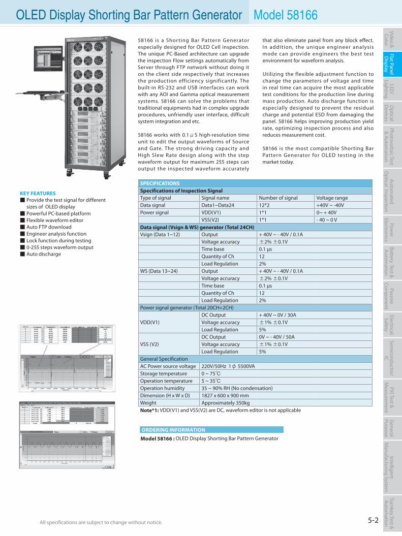
5-2All specifications are subject to change without notice. All specifications are subject to change without notice.
Flat PanelD
isplayPow
er Electronics
Electrical Safety
General
PurposePassive
Component
Semiconductor/
ICBattery Test & Autom
ationAutom
atedO
ptical Inspection Photovoltaic Test
& Automation
PXI Test &
Measurem
ent Video & Color
LED/
LightingO
ptical D
evicesIntelligent
Manufacturing System
Turnkey Test & Autom
ation
Model 58166 : OLED Display Shorting Bar Pattern Generator
ORDERING INFORMATION
Model 58166
KEY FEATURES Provide the test signal for different sizes of OLED display Powerful PC-based platform Flexible waveform editor Auto FTP download Engineer analysis function Lock function during testing 0-255 steps waveform output Auto discharge
SPECIFICATIONSSpecifications of Inspection SignalType of signal Signal name Number of signal Voltage rangeData signal Data1~Data24 12*2 +40V ~ -40VPower signal VDD(V1) 1*1 0~ + 40V
VSS(V2) 1*1 - 40 ~ 0 VData signal (Vsign & WS) generator (Total 24CH)Vsign (Data 1~12) Output + 40V ~ - 40V / 0.1A
Voltage accuracy ±2% ±0.1VTime base 0.1 µsQuantity of Ch 12Load Regulation 2%
WS (Data 13~24) Output + 40V ~ - 40V / 0.1AVoltage accuracy ±2% ±0.1VTime base 0.1 µsQuantity of Ch 12Load Regulation 2%
Power signal generator (Total 20CH+2CH)
VDD(V1)DC Output + 40V ~ 0V / 30AVoltage accuracy ±1% ±0.1VLoad Regulation 5%
VSS (V2)DC Output 0V ~ - 40V / 50AVoltage accuracy ±1% ±0.1VLoad Regulation 5%
General SpecificationAC Power source voltage 220V/50Hz 1φ 5500VAStorage temperature 0 ~ 75Operation temperature 5 ~ 35Operation humidity 35 ~ 90% RH (No condensation)Dimension (H x W x D) 1827 x 600 x 900 mmWeight Approximately 350kgNote*1: VDD(V1) and VSS(V2) are DC, waveform editor is not applicable
58166 is a Shorting Bar Pattern Generator especially designed for OLED Cell inspection. The unique PC-Based architecture can upgrade the inspection Flow settings automatically from Server through FTP network without doing it on the client side respectively that increases the production efficiency significantly. The built-in RS-232 and USB interfaces can work with any AOI and Gamma optical measurement systems. 58166 can solve the problems that traditional equipments had in complex upgrade procedures, unfriendly user interface, difficult system integration and etc.
58166 works with 0.1μS high-resolution time unit to edit the output waveforms of Source and Gate. The strong driving capacity and High Slew Rate design along with the step waveform output for maximum 255 steps can output the inspected waveform accurately
that also eliminate panel from any block effect. In addition, the unique engineer analysis mode can provide engineers the best test environment for waveform analysis.
Utilizing the flexible adjustment function to change the parameters of voltage and time in real time can acquire the most applicable test conditions for the production line during mass production. Auto discharge function is especially designed to prevent the residual charge and potential ESD from damaging the panel. 58166 helps improving production yield rate, optimizing inspection process and also reduces measurement cost.
58166 is the most compatible Shorting Bar Pattern Generator for OLED testing in the market today.
OLED Display Shorting Bar Pattern Generator
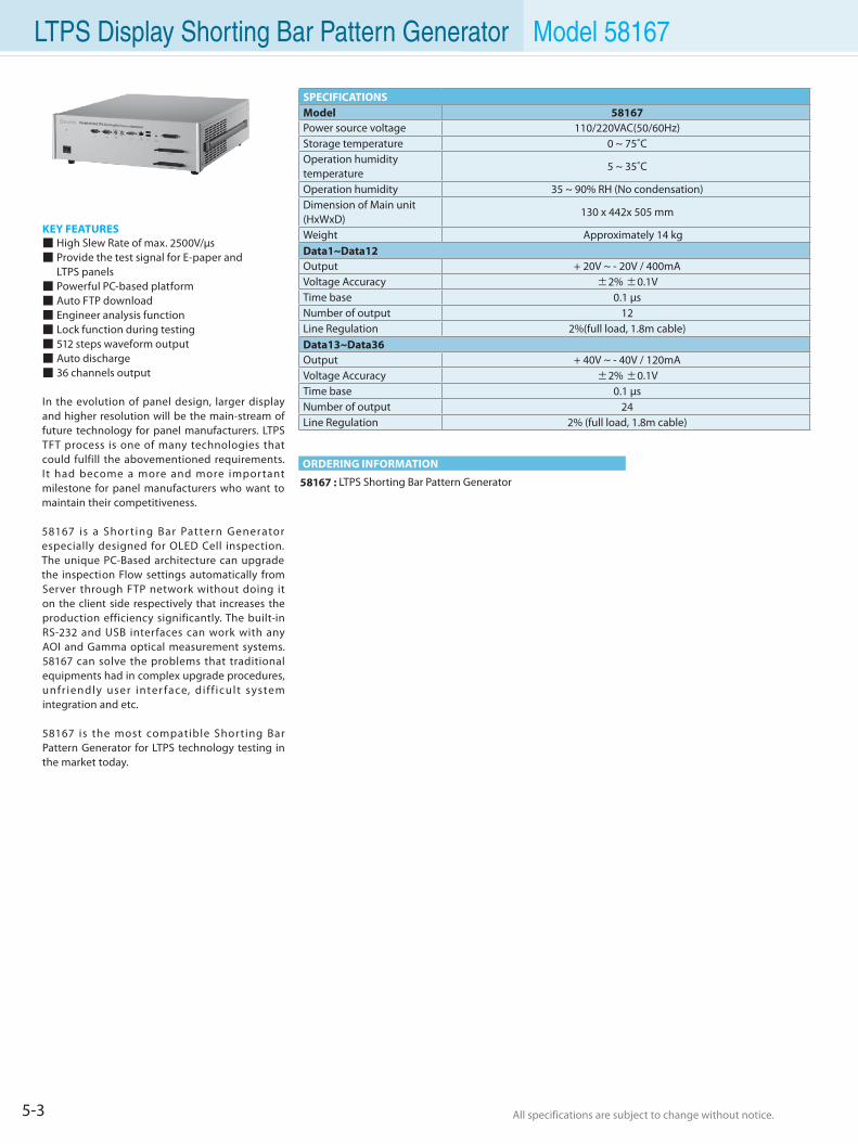
5-3 All specifications are subject to change without notice. All specifications are subject to change without notice.
Model 58167
KEY FEATURES High Slew Rate of max. 2500V/µs Provide the test signal for E-paper and LTPS panels Powerful PC-based platform Auto FTP download Engineer analysis function Lock function during testing 512 steps waveform output Auto discharge 36 channels output
In the evolution of panel design, larger display and higher resolution will be the main-stream of future technology for panel manufacturers. LTPS TFT process is one of many technologies that could fulfill the abovementioned requirements. I t had become a more and more important milestone for panel manufacturers who want to maintain their competitiveness.
58167 is a Shor t ing Bar Pattern Generator especially designed for OLED Cell inspection. The unique PC-Based architecture can upgrade the inspection Flow settings automatically from Server through FTP network without doing it on the client side respectively that increases the production efficiency significantly. The built-in RS-232 and USB interfaces can work with any AOI and Gamma optical measurement systems. 58167 can solve the problems that traditional equipments had in complex upgrade procedures, unfr iendly user inter face, di f f icult system integration and etc.
58167 is the most compatible Shorting Bar Pattern Generator for LTPS technology testing in the market today.
58167 : LTPS Shorting Bar Pattern Generator
ORDERING INFORMATION
SPECIFICATIONSModel 58167Power source voltage 110/220VAC(50/60Hz)Storage temperature 0 ~ 75˚COperation humidity temperature
5 ~ 35˚C
Operation humidity 35 ~ 90% RH (No condensation)Dimension of Main unit (HxWxD)
130 x 442x 505 mm
Weight Approximately 14 kgData1~Data12Output + 20V ~ - 20V / 400mAVoltage Accuracy ±2% ±0.1VTime base 0.1 µsNumber of output 12Line Regulation 2%(full load, 1.8m cable)Data13~Data36Output + 40V ~ - 40V / 120mAVoltage Accuracy ±2% ±0.1VTime base 0.1 µsNumber of output 24Line Regulation 2% (full load, 1.8m cable)
LTPS Display Shorting Bar Pattern Generator
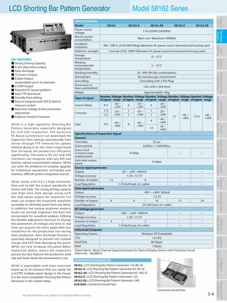
5-4All specifications are subject to change without notice. All specifications are subject to change without notice.
Flat PanelD
isplayPow
er Electronics
Electrical Safety
General
PurposePassive
Component
Semiconductor/
ICBattery Test & Autom
ationAutom
atedO
ptical Inspection Photovoltaic Test
& Automation
PXI Test &
Measurem
ent Video & Color
LED/
LightingO
ptical D
evicesIntelligent
Manufacturing System
Turnkey Test & Autom
ation LCD Shorting Bar Pattern Generator Model 58162 Series
KEY FEATURES Strong Driving Capacity 0-255 step waves output Auto discharge 12 Source Output 8 Gate Output (expandable up to 16 channels) 4 COM Output Powerful PC-based platform Auto FTP download Friendly Flow editing Easy to integrate with AOI & Optical measure system Real-time voltage & time parameter adjustment Engineer Analysis Function
58162 is a high capabi l i ty Shor t ing Bar Pattern Generator especia l ly des igned fo r LC D Ce l l i n s p e c t i o n. Th e e xc l u s i ve PC-Based architecture can download the inspection Flow settings automatically from Ser ver through FTP network for update without doing it on the client respectively that increases the production efficiency significantly. The built-in RS-232 and USB interfaces can integrate with any AOI and Gamma optical measurement systems. 58162 can solve the problems of complex upgrade for traditional equipment, unfriendly user interface, difficult system integration and etc.
58162 works with 0.5μS high-resolution time unit to edit the output waveforms of Source and Gate. The strong driving capacity and H igh S lew R ate des ign a long with the step waves output for maximum 512 steps can output the inspected waveform accurately to eliminate panel from any block. In addition the unique engineer analysis mode can provide engineers the best test environment for waveform analysis. Utilizing the flexible adjustment function to change the parameters of voltage and time in real time can acquire the most applicable test conditions for the production line during mass production. Auto discharge function is especially designed to prevent the residual charge and ESD from damaging the panel. 58162 not only increases the panel defect inspection ability, reduce the inspection process but also improve the production yield rate and lower down the measurement cost.
58162 is expandable with Gate extension board up to 24 channels that can satisfy the a-Si/LTPS multiple panel design in the future. It is the most compatible Shorting Bar Pattern Generator in the market today.
58162 : LCD Shorting Bar Pattern Generator 12S-8G-4C58162-A : LCD Shorting Bar Pattern Generator 6S-4G-2C58162-AE : LCD Shorting Bar Pattern Generator 6S-16G-2C58162-E : LCD Shorting Bar Pattern Generator 12G58162-EE : LCD Shorting Bar Pattern Generator 24GA581600 : Conversion board box
ORDERING INFORMATION
SPECIFICATIONSModel 58162 58162-A 58162-AE 58162-E 58162-EEPower source voltage 110/220VAC(50/60Hz)
Electric power consumption Main unit : Maximum 500Watt
Insulation resistance Min. 10MΩ at DC500V Mega (Between AC power source terminal and housing case)
Dielectric strength 1 minute of AC 1000V (Between AC power source terminal and housing case)Storage temperature 0 ~ 75˚C
Workingenvironmental temperature
5 ~ 35˚C
Working humidity 35 - 90% RH (No condensation)Atmosphere No corrosive gas environmentGrounding Grounding with 3-Pin-PlugDimension ofMain unit(HxWxD) 130 x 442 x 504 (mm)
Weight Approximately 14kg
Type of signal Number of signal
Voltage range
Number of signal
Voltage range
Number of signal
Voltage range
Number of signal
Voltage range
Number of signal
Voltage range
Source (Data) 6*2 -20 ~ +20V 6 -20 ~
+20V 6 -20 ~ +20V
12 -40 ~ +40V 12*2 -40 ~
+40V
Common1*2 -20 ~
+20V 1 -20 ~
+20V 1 -20 ~
+20V 1*2 1 1
Gate 4*2 -40 ~ +40V 4 -40 ~
+40V
4 -40 ~ +40V
12 -40 ~ +40V
Specifications of Inspection SignalGeneralTime base 0.5 µsFrame period 8,000us ~1,000,000usSource and Common total output power
75 Watt -- --
Gate total outputpower 75 Watt
Source signal generatorOutput -20 ~ +20V / 400mA -- --Voltage accuracy ±2% ±0.1V -- --Number of output 12 6 -- --Load Regulation 1.5%(full load, 2m cable) -- --Gate signal generatorOutput -40V ~ +40V/ 500mAVoltage accuracy ±0.2VNumber of output 8 4 16 12 24Load Regulation 2% (full load, 2m cable)DC Voltage generatorOutput -20V ~ +20V / 400mA -- --Voltage accuracy ±2% ±0.1V -- --Number of output 4 2 -- --Load Regulation 1.5%(full load, 2m cable) -- --Industrial ComputerOperating System Windows XP EmbeddedCPU 1.6 GHzHard Disk 80 GbyteRAM 1 GbytePatent Name : Multi-Channel Signal Generator for Optical Display Device with Protective CircuitPatent No. : 96208025
Conversion board box
Model 58167
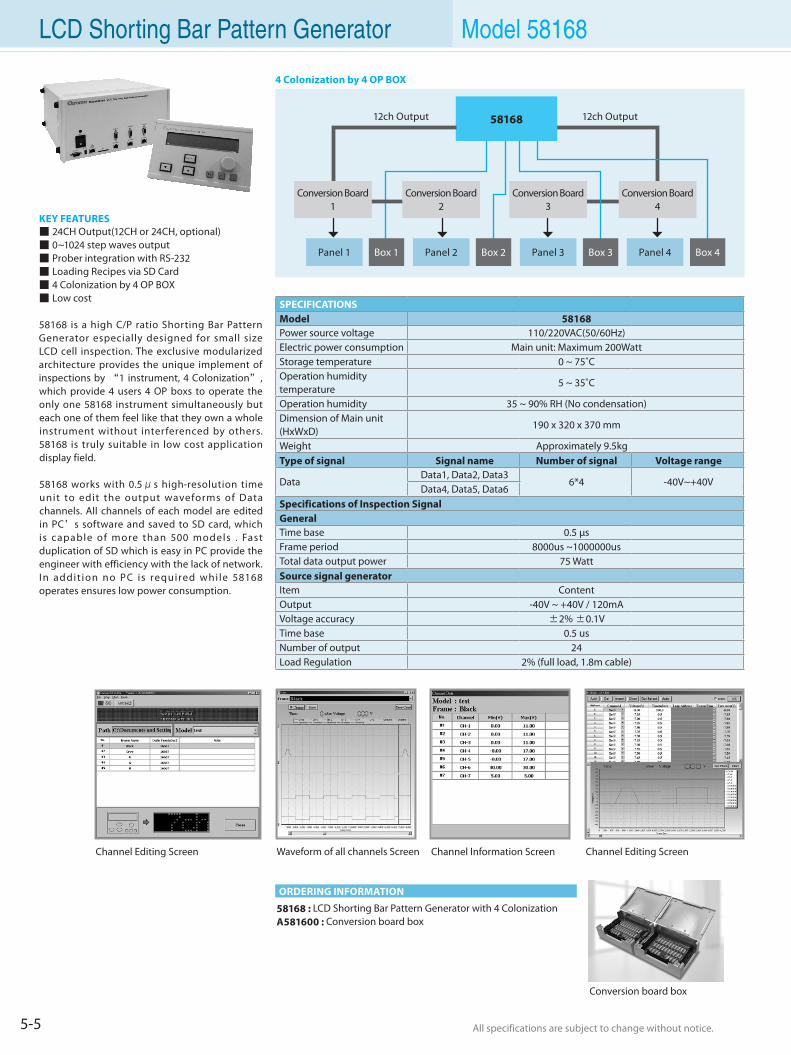
5-5 All specifications are subject to change without notice. All specifications are subject to change without notice.
LCD Shorting Bar Pattern Generator Model 58168
KEY FEATURES 24CH Output(12CH or 24CH, optional) 0~1024 step waves output Prober integration with RS-232 Loading Recipes via SD Card 4 Colonization by 4 OP BOX Low cost
58168 is a high C/P ratio Shorting Bar Pattern Generator especially designed for small size LCD cell inspection. The exclusive modularized architecture provides the unique implement of inspections by “1 instrument, 4 Colonization”, which provide 4 users 4 OP boxs to operate the only one 58168 instrument simultaneously but each one of them feel like that they own a whole instrument without interferenced by others. 58168 is truly suitable in low cost application display field.
58168 works with 0.5μs high-resolution time unit to edit the output waveforms of Data channels. All channels of each model are edited in PC’s software and saved to SD card, which is capable of more than 500 models . Fast duplication of SD which is easy in PC provide the engineer with efficiency with the lack of network. In addit ion no PC is required whi le 58168 operates ensures low power consumption.
58168 : LCD Shorting Bar Pattern Generator with 4 ColonizationA581600 : Conversion board box
ORDERING INFORMATION
SPECIFICATIONSModel 58168Power source voltage 110/220VAC(50/60Hz)Electric power consumption Main unit: Maximum 200WattStorage temperature 0 ~ 75˚COperation humidity temperature
5 ~ 35˚C
Operation humidity 35 ~ 90% RH (No condensation)Dimension of Main unit (HxWxD)
190 x 320 x 370 mm
Weight Approximately 9.5kgType of signal Signal name Number of signal Voltage range
DataData1, Data2, Data3
6*4 -40V~+40VData4, Data5, Data6
Specifications of Inspection SignalGeneralTime base 0.5 µsFrame period 8000us ~1000000usTotal data output power 75 WattSource signal generatorItem ContentOutput -40V ~ +40V / 120mAVoltage accuracy ±2% ±0.1VTime base 0.5 usNumber of output 24Load Regulation 2% (full load, 1.8m cable)
Channel Editing ScreenWaveform of all channels Screen
4 Colonization by 4 OP BOX
Channel Editing Screen Channel Information Screen
Conversion board box
Panel 1 Panel 2 Panel 3 Panel 4Box 1 Box 2 Box 3 Box 4
5816812ch Output 12ch Output
Conversion Board1
Conversion Board4
Conversion Board2
Conversion Board3
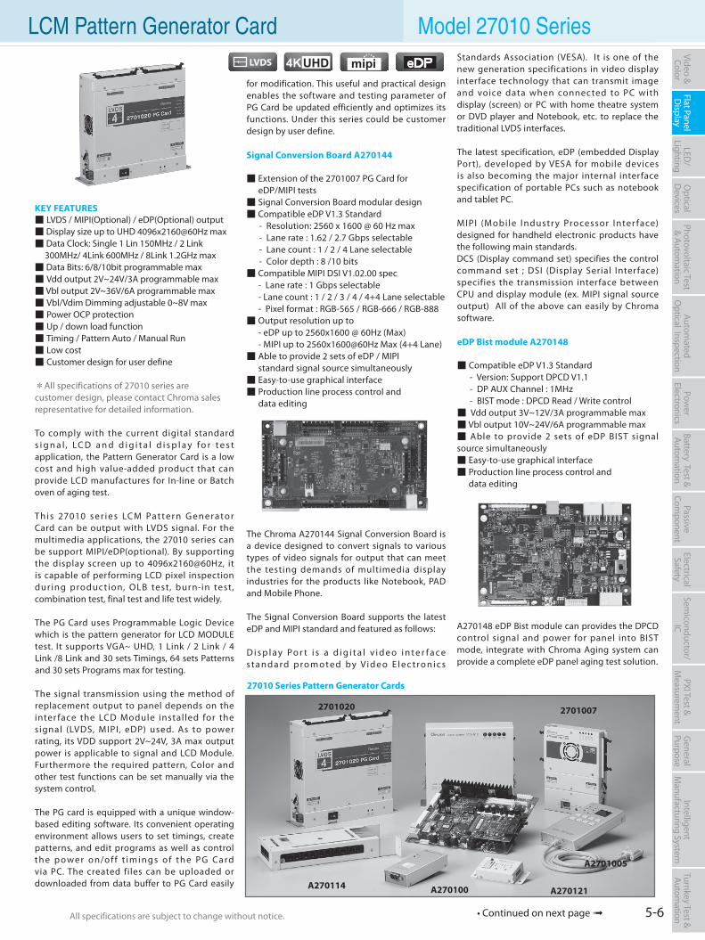
5-6All specifications are subject to change without notice. All specifications are subject to change without notice.
Flat PanelD
isplayPow
er Electronics
Electrical Safety
General
PurposePassive
Component
Semiconductor/
ICBattery Test & Autom
ationAutom
atedO
ptical Inspection Photovoltaic Test
& Automation
PXI Test &
Measurem
ent Video & Color
LED/
LightingO
ptical D
evicesIntelligent
Manufacturing System
Turnkey Test & Autom
ation LCM Pattern Generator Card Model 27010 Series
for modification. This useful and practical design enables the software and testing parameter of PG Card be updated efficiently and optimizes its functions. Under this series could be customer design by user define.
Signal Conversion Board A270144
Extension of the 2701007 PG Card for eDP/MIPI tests Signal Conversion Board modular design Compatible eDP V1.3 Standard - Resolution: 2560 x 1600 @ 60 Hz max - Lane rate : 1.62 / 2.7 Gbps selectable - Lane count : 1 / 2 / 4 Lane selectable - Color depth : 8 /10 bits Compatible MIPI DSI V1.02.00 spec - Lane rate : 1 Gbps selectable - Lane count : 1 / 2 / 3 / 4 / 4+4 Lane selectable - Pixel format : RGB-565 / RGB-666 / RGB-888 Output resolution up to - eDP up to 2560x1600 @ 60Hz (Max) - MIPI up to 2560x1600@60Hz Max (4+4 Lane) Able to provide 2 sets of eDP / MIPI standard signal source simultaneously Easy-to-use graphical interface Production line process control and data editing
The Chroma A270144 Signal Conversion Board is a device designed to convert signals to various types of video signals for output that can meet the testing demands of multimedia display industries for the products like Notebook, PAD and Mobile Phone.
The Signal Conversion Board supports the latest eDP and MIPI standard and featured as follows:
D i s p l a y Po r t i s a d i g i t a l v i d e o i n t e r f a c e s t a n d a rd p ro m o t e d by Vi d e o E l e c t ro n i c s
KEY FEATURES LVDS / MIPI(Optional) / eDP(Optional) output Display size up to UHD 4096x2160@60Hz max Data Clock: Single 1 Lin 150MHz / 2 Link 300MHz/ 4Link 600MHz / 8Link 1.2GHz max Data Bits: 6/8/10bit programmable max Vdd output 2V~24V/3A programmable max Vbl output 2V~36V/6A programmable max Vbl/Vdim Dimming adjustable 0~8V max Power OCP protection Up / down load function Timing / Pattern Auto / Manual Run Low cost Customer design for user define
*All specifications of 27010 series are customer design, please contact Chroma sales representative for detailed information.
To comply with the current digital standard s i g n a l , LC D a n d d i g i t a l d i s p l a y f o r t e s t application, the Pattern Generator Card is a low cost and high value-added product that can provide LCD manufactures for In-line or Batch oven of aging test.
Th i s 27010 s e r i e s LC M Pa t te r n G e n e ra to r Card can be output with LVDS signal. For the multimedia applications, the 27010 series can be support MIPI/eDP(optional). By supporting the display screen up to 4096x2160@60Hz, it is capable of performing LCD pixel inspection dur ing produc tion, OLB test, burn-in test, combination test, final test and life test widely.
The PG Card uses Programmable Logic Device which is the pattern generator for LCD MODULE test. It supports VGA~ UHD, 1 Link / 2 Link / 4 Link /8 Link and 30 sets Timings, 64 sets Patterns and 30 sets Programs max for testing.
The signal transmission using the method of replacement output to panel depends on the inter face the LCD Module installed for the signal (LVDS, MIPI, eDP) used. As to power rating, its VDD support 2V~24V, 3A max output power is applicable to signal and LCD Module. Furthermore the required pattern, Color and other test functions can be set manually via the system control.
The PG card is equipped with a unique window-based editing software. Its convenient operating environment allows users to set timings, create patterns, and edit programs as well as control t h e p owe r o n/o f f t i m i n g s o f t h e P G Ca rd via PC. The created files can be uploaded or downloaded from data buffer to PG Card easily
27010 Series Pattern Generator Cards
2701020 2701007
A270114 A270100 A270121
A2701005
• Continued on next page
Standards Association (VESA). It is one of the new generation specifications in video display interface technology that can transmit image and voice data when connected to PC with display (screen) or PC with home theatre system or DVD player and Notebook, etc. to replace the traditional LVDS interfaces.
The latest specification, eDP (embedded Display Port), developed by VESA for mobile devices is also becoming the major internal interface specification of portable PCs such as notebook and tablet PC.
MIPI (Mobile Industr y Processor Inter face) designed for handheld electronic products have the following main standards.DCS (Display command set) specifies the control command set ; DSI (Display Serial Inter face) specifies the transmission interface between CPU and display module (ex. MIPI signal source output) All of the above can easily by Chroma software.
eDP Bist module A270148
Compatible eDP V1.3 Standard - Version: Support DPCD V1.1 - DP AUX Channel : 1MHz - BIST mode : DPCD Read / Write control Vdd output 3V~12V/3A programmable max Vbl output 10V~24V/6A programmable max Able to provide 2 sets of eDP BIST signal source simultaneously Easy-to-use graphical interface Production line process control and data editing
A270148 eDP Bist module can provides the DPCD control signal and power for panel into BIST mode, integrate with Chroma Aging system can provide a complete eDP panel aging test solution.
4KUHD
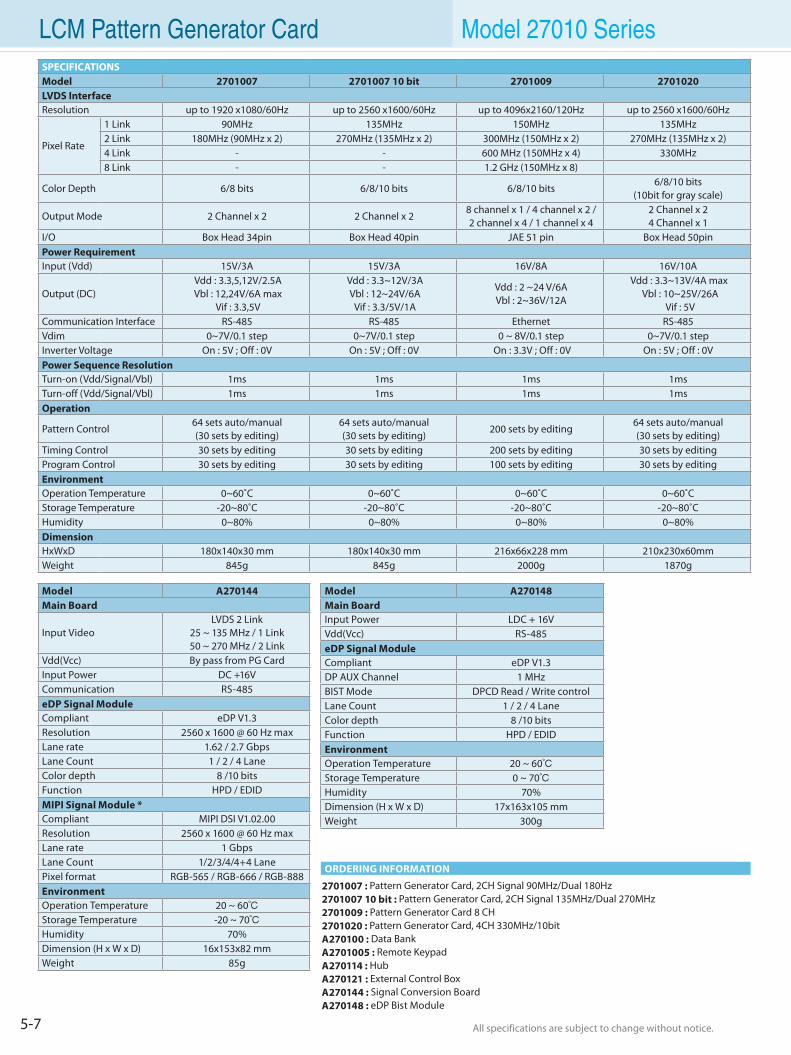
5-7 All specifications are subject to change without notice. All specifications are subject to change without notice.
LCM Pattern Generator Card Model 27010 Series
2701007 : Pattern Generator Card, 2CH Signal 90MHz/Dual 180Hz 2701007 10 bit : Pattern Generator Card, 2CH Signal 135MHz/Dual 270MHz2701009 : Pattern Generator Card 8 CH 2701020 : Pattern Generator Card, 4CH 330MHz/10bit A270100 : Data Bank A2701005 : Remote Keypad A270114 : HubA270121 : External Control Box A270144 : Signal Conversion BoardA270148 : eDP Bist Module
ORDERING INFORMATION
Model A270144Main Board
Input VideoLVDS 2 Link
25 ~ 135 MHz / 1 Link 50 ~ 270 MHz / 2 Link
Vdd(Vcc) By pass from PG CardInput Power DC +16VCommunication RS-485eDP Signal ModuleCompliant eDP V1.3Resolution 2560 x 1600 @ 60 Hz maxLane rate 1.62 / 2.7 GbpsLane Count 1 / 2 / 4 LaneColor depth 8 /10 bitsFunction HPD / EDIDMIPI Signal Module *Compliant MIPI DSI V1.02.00Resolution 2560 x 1600 @ 60 Hz maxLane rate 1 GbpsLane Count 1/2/3/4/4+4 LanePixel format RGB-565 / RGB-666 / RGB-888EnvironmentOperation Temperature 20 ~ 60Storage Temperature -20 ~ 70Humidity 70%Dimension (H x W x D) 16x153x82 mmWeight 85g
SPECIFICATIONSModel 2701007 2701007 10 bit 2701009 2701020LVDS InterfaceResolution up to 1920 x1080/60Hz up to 2560 x1600/60Hz up to 4096x2160/120Hz up to 2560 x1600/60Hz
Pixel Rate
1 Link 90MHz 135MHz 150MHz 135MHz2 Link 180MHz (90MHz x 2) 270MHz (135MHz x 2) 300MHz (150MHz x 2) 270MHz (135MHz x 2)4 Link - - 600 MHz (150MHz x 4) 330MHz8 Link - - 1.2 GHz (150MHz x 8)
Color Depth 6/8 bits 6/8/10 bits 6/8/10 bits 6/8/10 bits
(10bit for gray scale)
Output Mode 2 Channel x 2 2 Channel x 28 channel x 1 / 4 channel x 2 / 2 channel x 4 / 1 channel x 4
2 Channel x 24 Channel x 1
I/O Box Head 34pin Box Head 40pin JAE 51 pin Box Head 50pinPower RequirementInput (Vdd) 15V/3A 15V/3A 16V/8A 16V/10A
Output (DC) Vdd : 3.3,5,12V/2.5A Vbl : 12,24V/6A max
Vif : 3.3,5V
Vdd : 3.3~12V/3A Vbl : 12~24V/6A
Vif : 3.3/5V/1A
Vdd : 2 ~24 V/6AVbl : 2~36V/12A
Vdd : 3.3~13V/4A max Vbl : 10~25V/26A
Vif : 5VCommunication Interface RS-485 RS-485 Ethernet RS-485Vdim 0~7V/0.1 step 0~7V/0.1 step 0 ~ 8V/0.1 step 0~7V/0.1 stepInverter Voltage On : 5V ; Off : 0V On : 5V ; Off : 0V On : 3.3V ; Off : 0V On : 5V ; Off : 0VPower Sequence ResolutionTurn-on (Vdd/Signal/Vbl) 1ms 1ms 1ms 1msTurn-off (Vdd/Signal/Vbl) 1ms 1ms 1ms 1msOperation
Pattern Control64 sets auto/manual(30 sets by editing)
64 sets auto/manual(30 sets by editing)
200 sets by editing 64 sets auto/manual(30 sets by editing)
Timing Control 30 sets by editing 30 sets by editing 200 sets by editing 30 sets by editing Program Control 30 sets by editing 30 sets by editing 100 sets by editing 30 sets by editing EnvironmentOperation Temperature 0~60˚C 0~60˚C 0~60˚C 0~60˚CStorage Temperature -20~80˚C -20~80˚C -20~80˚C -20~80˚CHumidity 0~80% 0~80% 0~80% 0~80%DimensionHxWxD 180x140x30 mm 180x140x30 mm 216x66x228 mm 210x230x60mmWeight 845g 845g 2000g 1870g
Model A270148Main BoardInput Power LDC + 16VVdd(Vcc) RS-485 eDP Signal ModuleCompliant eDP V1.3DP AUX Channel 1 MHzBIST Mode DPCD Read / Write controlLane Count 1 / 2 / 4 LaneColor depth 8 /10 bitsFunction HPD / EDID EnvironmentOperation Temperature 20 ~ 60 Storage Temperature 0 ~ 70 Humidity 70%Dimension (H x W x D) 17x163x105 mmWeight 300g
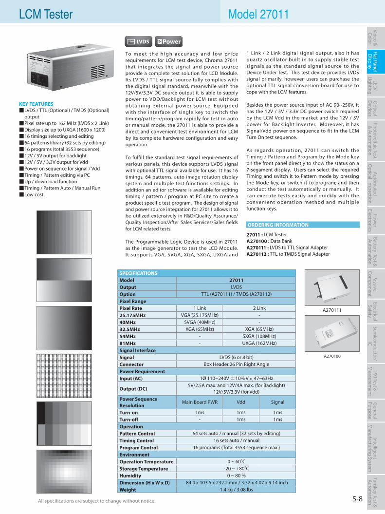
5-8All specifications are subject to change without notice. All specifications are subject to change without notice.
Flat PanelD
isplayPow
er Electronics
Electrical Safety
General
PurposePassive
Component
Semiconductor/
ICBattery Test & Autom
ationAutom
atedO
ptical Inspection Photovoltaic Test
& Automation
PXI Test &
Measurem
ent Video & Color
LED/
LightingO
ptical D
evicesIntelligent
Manufacturing System
Turnkey Test & Autom
ation LCM Tester Model 27011
To m e e t t h e h i g h a c c u r a c y a n d l o w p r i c e requirements for LCM test device, Chroma 27011 that integrates the signal and power source provide a complete test solution for LCD Module. Its LVDS / TTL signal source fully complies with the digital signal standard, meanwhile with the 12V/5V/3.3V DC source output it is able to supply power to VDD/Backlight for LCM test without obtaining external power source. Equipped with the interface of single key to switch the timing/pattern/program rapidly for test in auto or manual mode, the 27011 is able to provide a direct and convenient test environment for LCM by its complete hardware configuration and easy operation.
To fulfill the standard test signal requirements of various panels, this device supports LVDS signal with optional TTL signal available for use. It has 16 timings, 64 patterns, auto image rotation display system and multiple test functions settings. In addition an editor software is available for editing timing / pattern / program at PC site to create a product specific test program. The design of signal and power source integration for 27011 allows it to be utilized extensively in R&D/Quality Assurance/ Quality Inspection/After Sales Services/Sales fields for LCM related tests. The Programmable Logic Device is used in 27011 as the image generator to test the LCD Module. It supports VGA, SVGA, XGA, SXGA, UXGA and
1 Link / 2 Link digital signal output, also it has quartz oscillator built in to supply stable test signals as the standard signal source to the Device Under Test. This test device provides LVDS signal primarily, however, users can purchase the optional TTL signal conversion board for use to cope with the LCM features.
Besides the power source input of AC 90~250V, it has the 12V / 5V / 3.3V DC power switch required by the LCM Vdd in the market and the 12V / 5V power for Backlight Inverter. Moreover, it has Signal/Vdd power on sequence to fit in the LCM Turn On test sequence.
As regards operation, 27011 can switch the Timing / Pattern and Program by the Mode key on the front panel directly to show the status on a 7-segament display. Users can select the required Timing and switch it to Pattern mode by pressing the Mode key, or switch it to program; and then conduct the test automatically or manually. It can execute tests easily and quickly with the convenient operation method and multiple function keys.
KEY FEATURES LVDS / TTL (Optional) / TMDS (Optional) output Pixel rate up to 162 MHz (LVDS x 2 Link) Display size up to UXGA (1600 x 1200) 16 timings selecting and editing 64 patterns library (32 sets by editing) 16 programs (total 3553 sequence) 12V / 5V output for backlight 12V / 5V / 3.3V output for Vdd Power on sequence for signal / Vdd Timing / Pattern editing via PC Up / down load function Timing / Pattern Auto / Manual Run Low cost
27011 : LCM TesterA270100 : Data BankA270111 : LVDS to TTL Signal AdapterA270112 : TTL to TMDS Signal Adapter
SPECIFICATIONSModel 27011Output LVDSOption TTL (A270111) / TMDS (A270112)Pixel RangePixel Rate 1 Link 2 Link25.175MHz VGA (25.175MHz) -40MHz SVGA (40MHz) -32.5MHz XGA (65MHz) XGA (65MHz)54MHz - SXGA (108MHz)81MHz - UXGA (162MHz)Signal InterfaceSignal LVDS (6 or 8 bit)Connector Box Header 26 Pin Right AnglePower RequirementInput (AC) 1Ø 110~240V ±10% VLH, 47~63Hz
Output (DC) 5V/2.5A max. and 12V/4A max. (for Backlight)
12V/5V/3.3V (for Vdd)Power Sequence Resolution
Main Board PWR Vdd Signal
Turn-on 1ms 1ms 1msTurn-off - 1ms 1msOperationPattern Control 64 sets auto / manual (32 sets by editing)Timing Control 16 sets auto / manualProgram Control 16 programs (Total 3553 sequence max.)EnvironmentOperation Temperature 0 ~ 60˚CStorage Temperature -20 ~ +80˚CHumidity 0 ~ 80 %Dimension (H x W x D) 84.4 x 103.5 x 232.2 mm / 3.32 x 4.07 x 9.14 inchWeight 1.4 kg / 3.08 lbs
A270100
A270111
ORDERING INFORMATION
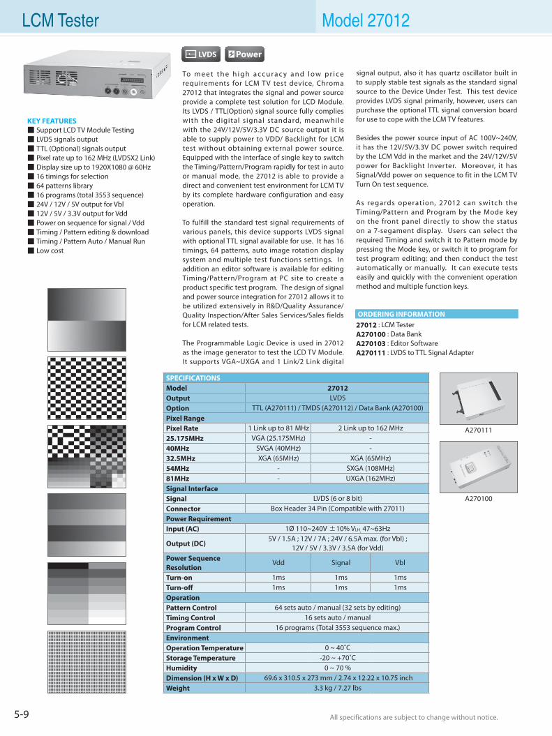
5-9 All specifications are subject to change without notice. All specifications are subject to change without notice.
LCM Tester Model 27012
To m e e t t h e h i g h a c c u r a c y a n d l o w p r i c e requirements for LCM T V test device, Chroma 27012 that integrates the signal and power source provide a complete test solution for LCD Module. Its LVDS / TTL(Option) signal source fully complies with the digital s ignal standard, meanwhile with the 24V/12V/5V/3.3V DC source output it is able to supply power to VDD/ Backlight for LCM test without obtaining external power source. Equipped with the interface of single key to switch the Timing/Pattern/Program rapidly for test in auto or manual mode, the 27012 is able to provide a direct and convenient test environment for LCM TV by its complete hardware configuration and easy operation.
To fulfill the standard test signal requirements of various panels, this device supports LVDS signal with optional TTL signal available for use. It has 16 timings, 64 patterns, auto image rotation display system and multiple test functions settings. In addition an editor software is available for editing Timing/Pattern/Program at PC site to create a product specific test program. The design of signal and power source integration for 27012 allows it to be utilized extensively in R&D/Quality Assurance/ Quality Inspection/After Sales Services/Sales fields for LCM related tests.
The Programmable Logic Device is used in 27012 as the image generator to test the LCD TV Module. It supports VGA~UXGA and 1 Link/2 Link digital
signal output, also it has quartz oscillator built in to supply stable test signals as the standard signal source to the Device Under Test. This test device provides LVDS signal primarily, however, users can purchase the optional TTL signal conversion board for use to cope with the LCM TV features.
Besides the power source input of AC 100V~240V, it has the 12V/5V/3.3V DC power switch required by the LCM Vdd in the market and the 24V/12V/5V power for Backlight Inverter. Moreover, it has Signal/Vdd power on sequence to fit in the LCM TV Turn On test sequence.
As regards operation, 27012 can switch the Timing/Pattern and Program by the Mode key on the front panel directly to show the status on a 7-segament display. Users can select the required Timing and switch it to Pattern mode by pressing the Mode key, or switch it to program for test program editing; and then conduct the test automatically or manually. It can execute tests easily and quickly with the convenient operation method and multiple function keys.
KEY FEATURES Support LCD TV Module Testing LVDS signals output TTL (Optional) signals output Pixel rate up to 162 MHz (LVDSX2 Link) Display size up to 1920X1080 @ 60Hz 16 timings for selection 64 patterns library 16 programs (total 3553 sequence) 24V / 12V / 5V output for Vbl 12V / 5V / 3.3V output for Vdd Power on sequence for signal / Vdd Timing / Pattern editing & download Timing / Pattern Auto / Manual Run Low cost
27012 : LCM TesterA270100 : Data BankA270103 : Editor SoftwareA270111 : LVDS to TTL Signal Adapter
SPECIFICATIONSModel 27012Output LVDSOption TTL (A270111) / TMDS (A270112) / Data Bank (A270100)Pixel RangePixel Rate 1 Link up to 81 MHz 2 Link up to 162 MHz25.175MHz VGA (25.175MHz) -40MHz SVGA (40MHz) -32.5MHz XGA (65MHz) XGA (65MHz)54MHz - SXGA (108MHz)81MHz - UXGA (162MHz)Signal InterfaceSignal LVDS (6 or 8 bit)Connector Box Header 34 Pin (Compatible with 27011)Power RequirementInput (AC) 1Ø 110~240V ±10% VLH, 47~63Hz
Output (DC) 5V / 1.5A ; 12V / 7A ; 24V / 6.5A max. (for Vbl) ;
12V / 5V / 3.3V / 3.5A (for Vdd)Power Sequence Resolution
Vdd Signal Vbl
Turn-on 1ms 1ms 1msTurn-off 1ms 1ms 1msOperationPattern Control 64 sets auto / manual (32 sets by editing)Timing Control 16 sets auto / manualProgram Control 16 programs (Total 3553 sequence max.)EnvironmentOperation Temperature 0 ~ 40˚CStorage Temperature -20 ~ +70˚CHumidity 0 ~ 70 %Dimension (H x W x D) 69.6 x 310.5 x 273 mm / 2.74 x 12.22 x 10.75 inchWeight 3.3 kg / 7.27 lbs
A270111
A270100
ORDERING INFORMATION
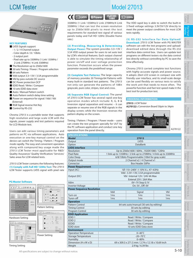
5-10All specifications are subject to change without notice. All specifications are subject to change without notice.
Flat PanelD
isplayPow
er Electronics
Electrical Safety
General
PurposePassive
Component
Semiconductor/
ICBattery Test & Autom
ationAutom
atedO
ptical Inspection Photovoltaic Test
& Automation
PXI Test &
Measurem
ent Video & Color
LED/
LightingO
ptical D
evicesIntelligent
Manufacturing System
Turnkey Test & Autom
ation LCM Tester Model 27013
330MHz (1 Link 135MHz/2 Link 270MHz/4 Link 330MHz ) that can test the screen resolution u p t o 2560x1600 p i xe l s t o m e e t t h e t e s t requirements for standard test signal of various panels today and Full HD 120Hz (Double frame rate.)
(2) Providing, Measuring & Determining Output Power: The system provides 3.3~13V / 3.5A VDD output power for users to set auto test by LCM's electrical features. Each output channel is able to simulate the timing relationship of power on/off and over voltage protection function. Protection occurs when the power parameter exceeds the predefined range.
(3) Complete Test Patterns: The large capacity of memory provides 30 Timings/64 Patterns with many built-in standard test patterns. The 27013 not only can generate the patterns of 10Bit grayscale, pure color, stripes, text and cross.
(4) Separate RGB Signal Control: The panel of 27013 LCM Tester has several rapid one-key operat ion modes which include: R, G, B & Inversion signal separation and resume – it can separate or resume one of the RGB signals in the display screen; while the Inversion reverses the pattern display on the screen.
Timing / Pattern / Program / Power mode – users can create the test program specially for UUT by the PC software application and conduct one-key operation from the panel directly.
The VDD rapid key is able to switch the built-in 3 fixed voltage settings 3.3V/5V/12V directly to meet the power output conditions for most LCM tests rapidly.
(5) R S -232 I n t e r f a c e f o r D a t a U p l o a d/ Download: 27013 LCM Tester with PG MASTER software can edit the test programs and upload/download edited data through the RS-232 interface data control box. Users can update test programs on different testers via the data control box directly without controlling by PC to save the time effectively.
Chroma 27013 carried complete test functions with highly accurate signals and power source. It adopts 20x4 LCD screen in compact size with friendly user interface, and its small-scale design can be used flexibly on various tests to satisfy the work unit that needs to move often. The powerful function and fast test speed make it the best tool for production test.
KEY FEATURES LVDS Signals support - 1 / 2 / 4 Channel output - Color depth 6 / 8 / 10bits - 2 output port - Pixel rate up to 330MHz (1 Link 135MHz / 2 Link 270MHz / 4 Link 330MHz) The Resolution up to 2560x1600 30 sets Timing / Power / Program selection 64 sets Pattern Vdd output 3.3~13V / 3.5A programmable Vbl by pass outside DC source DC Power protection OCP EDID Read / Write / Compare 10 sets EDID data store Auto / Manual Pattern switch Auto Pattern switch delay time setting Power on sequence for signal / Vdd / Vbl (External) RGB Signal reverse Hot Key Control by RS-232
Chroma 27013 is a portable tester that supports high resolution and large scale LCM with the signals, power supply and test patterns required for LCD Module test.
Users can edit various timing parameters and patterns on PC via software applications. Auto execution or one-key manual control on the device can switch the Timing / Pattern / Program mode rapidly. The easy and convenient operation along with compound key usage made the 27013 LCM Tester most applicable for R&D/ Quality Assurance/ Quality Verification/ Services/ Sales areas for LCM related tests.
27013 LCM Tester contains the following features: (1) Comply with Full HD 120Hz Test: The 27013 LCM Tester supports LVDS signal with pixel rate
27013 : LCM TesterA270122 : Conversion Board 50pin to 34pin
ORDERING INFORMATION
PG Master Software
Hardware Setting
Timing Setting
Pattern Setting
Power Setting
A270122
SPECIFICATIONSModel 27013Output LVDSOption DataBankLVDS interfaceResolution Up to 2560x1600 / 60Hz , 1920X1080 / 120HzPixel Rate 1 link up to 135MHz / 2 link up to 270MHz / 4 link up to 330MHzColor Deep 6/8/10bits Programmable (10bit for gray scale)Output mode 2 Channel x2 / 4 Channel x1Connector Box Header 50PinPower RequirementInput (AC) 1Ø 110~240V ±10% VLH, 47~63Hz
Output (DC) Vdd : 3.3V~13V, 3.5A programmable
Vbl : Internal 12V / 24V 4A MaxExtenal 25V / 26A Max
Vdim 0V~7V Step 0.1VInverter Voltage On: 5V , Off: 0V Power Sequence Resolution
Vdd Signal VblTurn-on 1ms 1ms 1msTuren-off 1ms 1ms 1msOperationPattern Control 64 sets auto/manual (30 sets by editing)Timing Control 30 sets by editingProgram Control 30 sets by editingEDID ApplicationEDID 1 Read / Write / CompareEDID 2 Read / Write / CompareEEDID Read / Write / CompareEDID store 10 sets EDID Data storeEnvironmentOperation Temperature 0~40˚CStorage Temperature -20~70˚CHumidity 0~80%Dimension (H x W x D) 69 x 309.3 x 271.5 mm / 2.74 x 12.18 x 10.69 inchWeight 2.9 kg / 6.39 lbs
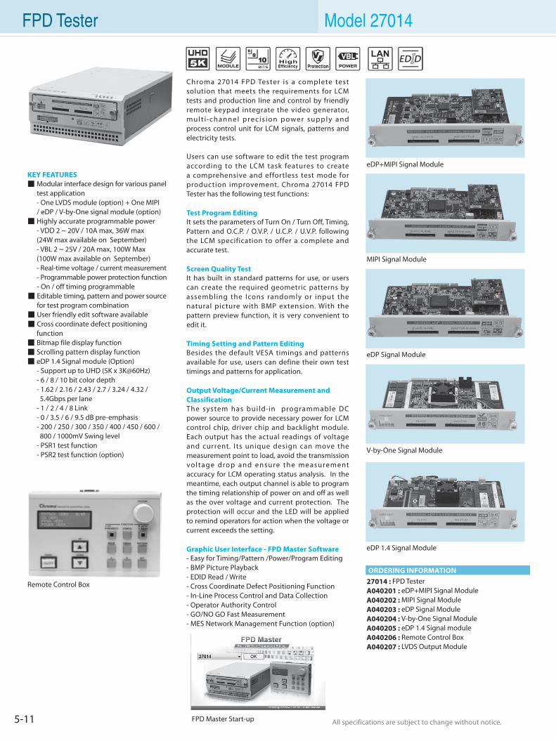
5-11 All specifications are subject to change without notice. All specifications are subject to change without notice.
FPD Tester Model 27014
Chroma 27014 FPD Tester is a complete test solution that meets the requirements for LCM tests and production line and control by friendly remote keypad integrate the video generator, mult i-channel prec is ion power supply and process control unit for LCM signals, patterns and electricity tests. Users can use software to edit the test program according to the LCM task features to create a comprehensive and effortless test mode for production improvement. Chroma 27014 FPD Tester has the following test functions: Test Program EditingIt sets the parameters of Turn On / Turn Off, Timing, Pattern and O.C.P. / O.V.P. / U.C.P. / U.V.P. following the LCM specification to offer a complete and accurate test. Screen Quality TestIt has built in standard patterns for use, or users can create the required geometric patterns by assembling the Icons randomly or input the natural picture with BMP extension. With the pattern preview function, it is very convenient to edit it.
Timing Setting and Pattern EditingBesides the default VESA timings and patterns available for use, users can define their own test timings and patterns for application.
Output Voltage/Current Measurement and ClassificationThe system has bui ld-in programmable DC power source to provide necessary power for LCM control chip, driver chip and backlight module. Each output has the actual readings of voltage and current. I ts unique design can move the measurement point to load, avoid the transmission voltage drop and ensure the measurement accuracy for LCM operating status analysis. In the meantime, each output channel is able to program the timing relationship of power on and off as well as the over voltage and current protection. The protection will occur and the LED will be applied to remind operators for action when the voltage or current exceeds the setting.
Graphic User Interface - FPD Master Software- Easy for Timing/Pattern /Power/Program Editing- BMP Picture Playback- EDID Read / Write - Cross Coordinate Defect Positioning Function- In-Line Process Control and Data Collection- Operator Authority Control- GO/NO GO Fast Measurement - MES Network Management Function (option)
KEY FEATURES Modular interface design for various panel test application - One LVDS module (option) + One MIPI / eDP / V-by-One signal module (option) Highly accurate programmable power - VDD 2 ~ 20V / 10A max, 36W max (24W max available on September) - VBL 2 ~ 25V / 20A max, 100W Max (100W max available on September) - Real-time voltage / current measurement - Programmable power protection function - On / off timing programmable Editable timing, pattern and power source for test program combination User friendly edit software available Cross coordinate defect positioning function Bitmap file display function Scrolling pattern display function eDP 1.4 Signal module (Option) - Support up to UHD (5K x 3K@60Hz) - 6 / 8 / 10 bit color depth - 1.62 / 2.16 / 2.43 / 2.7 / 3.24 / 4.32 / 5.4Gbps per lane - 1 / 2 / 4 / 8 Link - 0 / 3.5 / 6 / 9.5 dB pre-emphasis - 200 / 250 / 300 / 350 / 400 / 450 / 600 / 800 / 1000mV Swing level - PSR1 test function - PSR2 test function (option)
27014 : FPD TesterA040201 : eDP+MIPI Signal ModuleA040202 : MIPI Signal ModuleA040203 : eDP Signal ModuleA040204 : V-by-One Signal ModuleA040205 : eDP 1.4 Signal moduleA040206 : Remote Control BoxA040207 : LVDS Output Module
FPD Master Start-up
eDP+MIPI Signal Module
MIPI Signal Module
eDP Signal Module
V-by-One Signal Module
eDP 1.4 Signal Module
Remote Control Box
ORDERING INFORMATION
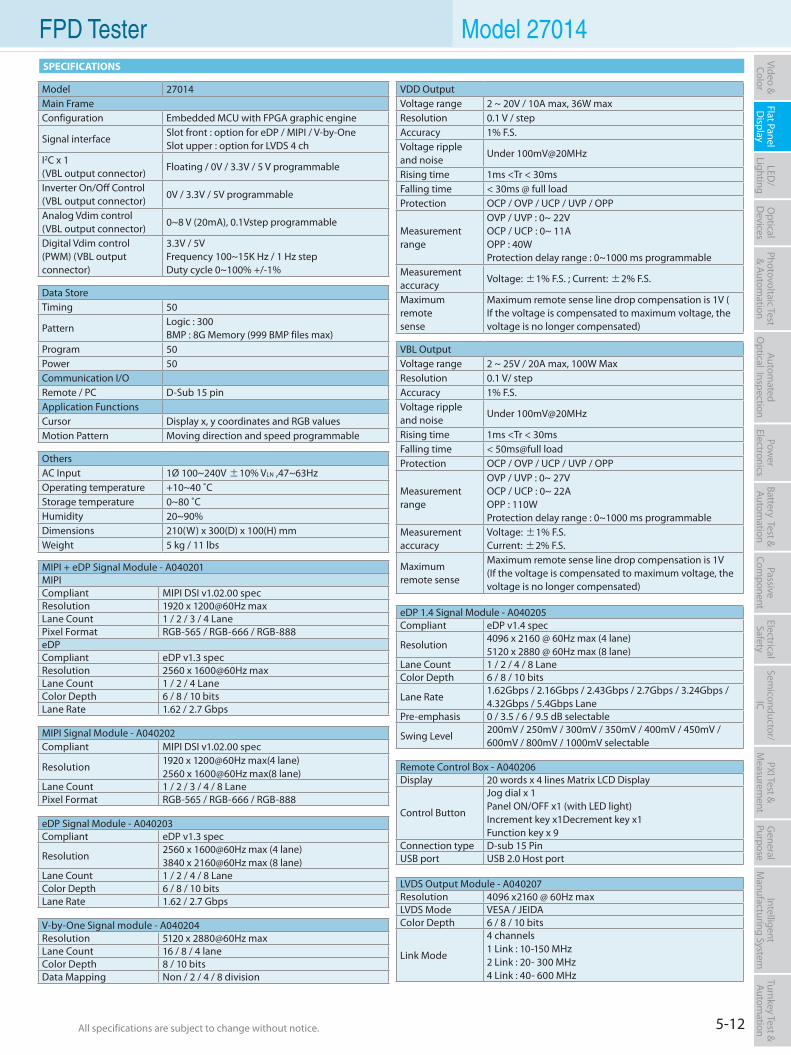
5-12All specifications are subject to change without notice. All specifications are subject to change without notice.
Flat PanelD
isplayPow
er Electronics
Electrical Safety
General
PurposePassive
Component
Semiconductor/
ICBattery Test & Autom
ationAutom
atedO
ptical Inspection Photovoltaic Test
& Automation
PXI Test &
Measurem
ent Video & Color
LED/
LightingO
ptical D
evicesIntelligent
Manufacturing System
Turnkey Test & Autom
ation FPD Tester Model 27014SPECIFICATIONS
Model 27014Main FrameConfiguration Embedded MCU with FPGA graphic engine
Signal interfaceSlot front : option for eDP / MIPI / V-by-OneSlot upper : option for LVDS 4 ch
I2C x 1(VBL output connector)
Floating / 0V / 3.3V / 5 V programmable
Inverter On/Off Control(VBL output connector)
0V / 3.3V / 5V programmable
Analog Vdim control(VBL output connector)
0~8 V (20mA), 0.1Vstep programmable
Digital Vdim control (PWM) (VBL output connector)
3.3V / 5VFrequency 100~15K Hz / 1 Hz stepDuty cycle 0~100% +/-1%
Data StoreTiming 50
PatternLogic : 300BMP : 8G Memory (999 BMP files max)
Program 50Power 50Communication I/ORemote / PC D-Sub 15 pinApplication FunctionsCursor Display x, y coordinates and RGB valuesMotion Pattern Moving direction and speed programmable
VDD OutputVoltage range 2 ~ 20V / 10A max, 36W maxResolution 0.1 V / stepAccuracy 1% F.S.Voltage rippleand noise
Under 100mV@20MHz
Rising time 1ms <Tr < 30msFalling time < 30ms @ full loadProtection OCP / OVP / UCP / UVP / OPP
Measurementrange
OVP / UVP : 0~ 22VOCP / UCP : 0~ 11AOPP : 40WProtection delay range : 0~1000 ms programmable
Measurementaccuracy
Voltage: ±1% F.S. ; Current: ±2% F.S.
Maximumremotesense
Maximum remote sense line drop compensation is 1V ( If the voltage is compensated to maximum voltage, the voltage is no longer compensated)
VBL OutputVoltage range 2 ~ 25V / 20A max, 100W Max Resolution 0.1 V/ stepAccuracy 1% F.S.Voltage ripple and noise
Under 100mV@20MHz
Rising time 1ms <Tr < 30msFalling time < 50ms@full loadProtection OCP / OVP / UCP / UVP / OPP
Measurement range
OVP / UVP : 0~ 27VOCP / UCP : 0~ 22AOPP : 110WProtection delay range : 0~1000 ms programmable
Measurement accuracy
Voltage: ±1% F.S.Current: ±2% F.S.
Maximumremote sense
Maximum remote sense line drop compensation is 1V (If the voltage is compensated to maximum voltage, the voltage is no longer compensated)
OthersAC Input 1Ø 100~240V ±10% VLN ,47~63HzOperating temperature +10~40 ˚CStorage temperature 0~80 ˚CHumidity 20~90%Dimensions 210(W) x 300(D) x 100(H) mm Weight 5 kg / 11 lbs
eDP 1.4 Signal Module - A040205Compliant eDP v1.4 spec
Resolution4096 x 2160 @ 60Hz max (4 lane) 5120 x 2880 @ 60Hz max (8 lane)
Lane Count 1 / 2 / 4 / 8 LaneColor Depth 6 / 8 / 10 bits
Lane Rate1.62Gbps / 2.16Gbps / 2.43Gbps / 2.7Gbps / 3.24Gbps / 4.32Gbps / 5.4Gbps Lane
Pre-emphasis 0 / 3.5 / 6 / 9.5 dB selectable
Swing Level200mV / 250mV / 300mV / 350mV / 400mV / 450mV / 600mV / 800mV / 1000mV selectable
eDP Signal Module - A040203Compliant eDP v1.3 spec
Resolution2560 x 1600@60Hz max (4 lane)3840 x 2160@60Hz max (8 lane)
Lane Count 1 / 2 / 4 / 8 LaneColor Depth 6 / 8 / 10 bitsLane Rate 1.62 / 2.7 Gbps
MIPI + eDP Signal Module - A040201MIPICompliant MIPI DSI v1.02.00 specResolution 1920 x 1200@60Hz maxLane Count 1 / 2 / 3 / 4 LanePixel Format RGB-565 / RGB-666 / RGB-888eDPCompliant eDP v1.3 specResolution 2560 x 1600@60Hz maxLane Count 1 / 2 / 4 LaneColor Depth 6 / 8 / 10 bitsLane Rate 1.62 / 2.7 Gbps
MIPI Signal Module - A040202Compliant MIPI DSI v1.02.00 spec
Resolution1920 x 1200@60Hz max(4 lane)2560 x 1600@60Hz max(8 lane)
Lane Count 1 / 2 / 3 / 4 / 8 LanePixel Format RGB-565 / RGB-666 / RGB-888
V-by-One Signal module - A040204Resolution 5120 x 2880@60Hz maxLane Count 16 / 8 / 4 laneColor Depth 8 / 10 bitsData Mapping Non / 2 / 4 / 8 division
LVDS Output Module - A040207Resolution 4096 x2160 @ 60Hz maxLVDS Mode VESA / JEIDAColor Depth 6 / 8 / 10 bits
Link Mode
4 channels1 Link : 10-150 MHz 2 Link : 20- 300 MHz4 Link : 40- 600 MHz
Remote Control Box - A040206Display 20 words x 4 lines Matrix LCD Display
Control Button
Jog dial x 1Panel ON/OFF x1 (with LED light)Increment key x1Decrement key x1Function key x 9
Connection type D-sub 15 Pin USB port USB 2.0 Host port
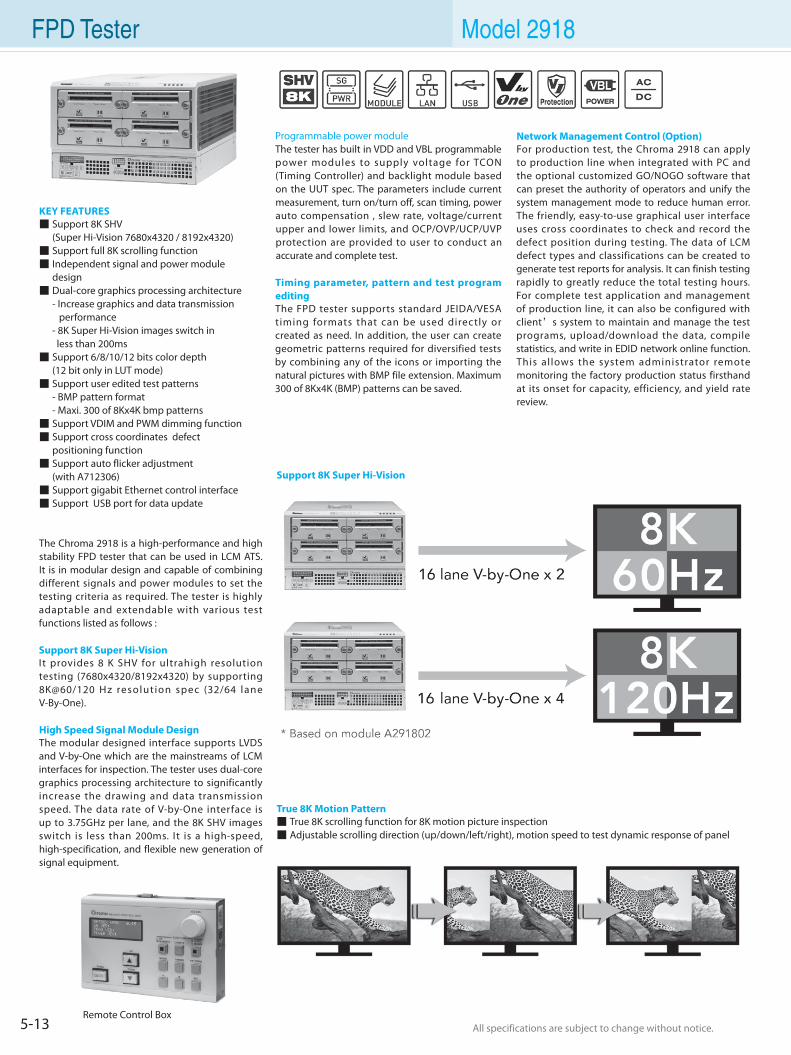
5-13 All specifications are subject to change without notice. All specifications are subject to change without notice.
FPD Tester Model 2918
KEY FEATURES Support 8K SHV (Super Hi-Vision 7680x4320 / 8192x4320) Support full 8K scrolling function Independent signal and power module design Dual-core graphics processing architecture - Increase graphics and data transmission performance - 8K Super Hi-Vision images switch in less than 200ms Support 6/8/10/12 bits color depth (12 bit only in LUT mode) Support user edited test patterns - BMP pattern format - Maxi. 300 of 8Kx4K bmp patterns Support VDIM and PWM dimming function Support cross coordinates defect positioning function Support auto flicker adjustment (with A712306) Support gigabit Ethernet control interface Support USB port for data update
The Chroma 2918 is a high-performance and high stability FPD tester that can be used in LCM ATS. It is in modular design and capable of combining different signals and power modules to set the testing criteria as required. The tester is highly adaptable and extendable with various test functions listed as follows :
Support 8K Super Hi-VisionI t provides 8 K SHV for ultrahigh resolution testing (7680x4320/8192x4320) by supporting 8K@60/120 H z resolut ion spec (32/64 lane V-By-One).
High Speed Signal Module DesignThe modular designed interface supports LVDS and V-by-One which are the mainstreams of LCM interfaces for inspection. The tester uses dual-core graphics processing architecture to significantly increase the drawing and data transmission speed. The data rate of V-by-One interface is up to 3.75GHz per lane, and the 8K SHV images switch is less than 200ms. It is a high-speed, high-specification, and flexible new generation of signal equipment.
Programmable power module The tester has built in VDD and VBL programmable power modules to supply voltage for TCON (Timing Controller) and backlight module based on the UUT spec. The parameters include current measurement, turn on/turn off, scan timing, power auto compensation , slew rate, voltage/current upper and lower limits, and OCP/OVP/UCP/UVP protection are provided to user to conduct an accurate and complete test.
Timing parameter, pattern and test program editing The FPD tester supports standard JEIDA/VESA timing formats that can be used directly or created as need. In addition, the user can create geometric patterns required for diversified tests by combining any of the icons or importing the natural pictures with BMP file extension. Maximum 300 of 8Kx4K (BMP) patterns can be saved.
Network Management Control (Option) For production test, the Chroma 2918 can apply to production line when integrated with PC and the optional customized GO/NOGO software that can preset the authority of operators and unify the system management mode to reduce human error. The friendly, easy-to-use graphical user interface uses cross coordinates to check and record the defect position during testing. The data of LCM defect types and classifications can be created to generate test reports for analysis. It can finish testing rapidly to greatly reduce the total testing hours. For complete test application and management of production line, it can also be configured with client’s system to maintain and manage the test programs, upload/download the data, compile statistics, and write in EDID network online function. This allows the system administrator remote monitoring the factory production status firsthand at its onset for capacity, efficiency, and yield rate review.
Support 8K Super Hi-Vision
True 8K Motion Pattern True 8K scrolling function for 8K motion picture inspection Adjustable scrolling direction (up/down/left/right), motion speed to test dynamic response of panel
Remote Control Box
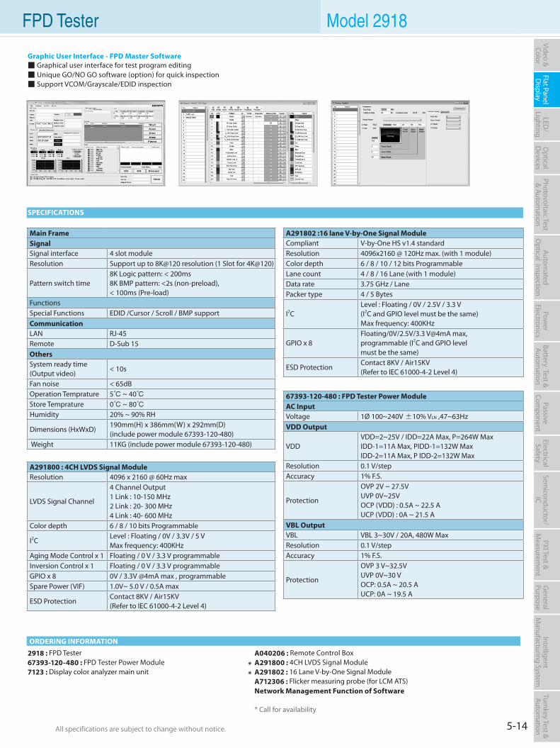
5-14All specifications are subject to change without notice. All specifications are subject to change without notice.
Flat PanelD
isplayPow
er Electronics
Electrical Safety
General
PurposePassive
Component
Semiconductor/
ICBattery Test & Autom
ationAutom
atedO
ptical Inspection Photovoltaic Test
& Automation
PXI Test &
Measurem
ent Video & Color
LED/
LightingO
ptical D
evicesIntelligent
Manufacturing System
Turnkey Test & Autom
ation FPD Tester Model 2918
2918 : FPD Tester67393-120-480 : FPD Tester Power Module7123 : Display color analyzer main unit
A040206 : Remote Control BoxA291800 : 4CH LVDS Signal ModuleA291802 : 16 Lane V-by-One Signal ModuleA712306 : Flicker measuring probe (for LCM ATS)Network Management Function of Software
* Call for availability
ORDERING INFORMATION
SPECIFICATIONS
Main Frame Signal Signal interface 4 slot moduleResolution Support up to 8K@120 resolution (1 Slot for 4K@120)
Pattern switch time8K Logic pattern: < 200ms8K BMP pattern: <2s (non-preload),< 100ms (Pre-load)
FunctionsSpecial Functions EDID /Cursor / Scroll / BMP supportCommunicationLAN RJ-45Remote D-Sub 15Others System ready time(Output video)
< 10s
Fan noise < 65dBOperation Temprature 5 ~ 40Store Temprature 0 ~ 80Humidity 20% ~ 90% RH
Dimensions (HxWxD)190mm(H) x 386mm(W) x 292mm(D)(include power module 67393-120-480)
Weight 11KG (include power module 67393-120-480)
67393-120-480 : FPD Tester Power ModuleAC InputVoltage 1Ø 100~240V ±10% VLN ,47~63HzVDD Output
VDDVDD=2~25V / IDD=22A Max, P=264W MaxIDD-1=11A Max, PIDD-1=132W MaxIDD-2=11A Max, P IDD-2=132W Max
Resolution 0.1 V/stepAccuracy 1% F.S.
Protection
OVP 2V ~ 27.5V UVP 0V~25V OCP (VDD) : 0.5A ~ 22.5 A UCP (VDD) : 0A ~ 21.5 A
VBL OutputVBL VBL 3~30V / 20A, 480W Max Resolution 0.1 V/stepAccuracy 1% F.S.
Protection
OVP 3 V~32.5V UVP 0V~30 V OCP: 0.5A ~ 20.5 A UCP: 0A ~ 19.5 A
A291800 : 4CH LVDS Signal ModuleResolution 4096 x 2160 @ 60Hz max
LVDS Signal Channel
4 Channel Output1 Link : 10-150 MHz2 Link : 20- 300 MHz4 Link : 40- 600 MHz
Color depth 6 / 8 / 10 bits Programmable
I2CLevel : Floating / 0V / 3.3V / 5 VMax frequency: 400KHz
Aging Mode Control x 1 Floating / 0 V / 3.3 V programmableInversion Control x 1 Floating / 0 V / 3.3 V programmableGPIO x 8 0V / 3.3V @4mA max , programmableSpare Power (VIF) 1.0V~ 5.0 V / 0.5A max
ESD ProtectionContact 8KV / Air15KV(Refer to IEC 61000-4-2 Level 4)
A291802 :16 lane V-by-One Signal ModuleCompliant V-by-One HS v1.4 standardResolution 4096x2160 @ 120Hz max. (with 1 module)Color depth 6 / 8 / 10 / 12 bits ProgrammableLane count 4 / 8 / 16 Lane (with 1 module)Data rate 3.75 GHz / LanePacker type 4 / 5 Bytes
I2CLevel : Floating / 0V / 2.5V / 3.3 V (I2C and GPIO level must be the same)Max frequency: 400KHz
GPIO x 8Floating/0V/2.5V/3.3 V@4mA max,programmable (I2C and GPIO level must be the same)
ESD ProtectionContact 8KV / Air15KV(Refer to IEC 61000-4-2 Level 4)
Graphic User Interface - FPD Master Software Graphical user interface for test program editing Unique GO/NO GO software (option) for quick inspection Support VCOM/Grayscale/EDID inspection
**
5-15 All specifications are subject to change without notice. All specifications are subject to change without notice.
LCM ATS Model 29133/29135
KEY FEATURES For full HD measurement True Color computer base LCM Testing LVDS/TTL(OPT)/TMDS signals support (29130 LVDS 8 bit only) Display Up to WUXGA @ 60Hz Precise programmable DC source Extension Power control (option) Power protection OVP/OCP/UVP/UCP Voltage/Current measurement GO/NOGO fast measurement Easy for Timing/Pattern/Program editing Unlimited Timing/Pattern/Program storage EDID read/write/compare LCM failure code editing & record Cross Mark for cell checking JPG/BMP/AVI/MPEG file support Keypad operation Special I/O Network management function (option) Production line process control and data
collection
The Chroma 29133/29135 LCM Automatic Test System (ATS) which is structured in computer based system with powerful on-line network function and easy-to-use interface is designed to fulfill the key requirements of LCM tests and the production line management theory from factory. By integrating the video generator, multi-channel precision power supply and process control unit, the LCM ATS is capable of providing complete test solutions for LCM signals, patterns and electricity.
The test programs performed by LCM ATS tasks can be edited by the embedded test editor. The mouse and remote keypads used by the test program editor give the production line a most complete and convenient test mode to expedite the productivity. The test functions Chroma 29133/29135 LCM ATS have are:
Test Program EditorIt contains the parameters settings of power Turn On/ Turn Off, scanning timing, pattern, over and under voltage/current protection (OCP/OVP/UCP/UVP), and real-time voltage Ramp Up/Ramp Down based on the LCM electricity specifications for accurate and comprehensive tests.
Screen Quality TestBesides the built-in standard patterns, users can define the geometry patterns that composed of various ICONs; moreover, the natural picture file with BMP/JPG filename extension can be imported. In addition the animation function is available for the LCD Response time test. All patterns can be scaled automatically according to the LCM resolution to facilitate the pattern editing preview function.
Timing Setting and Pattern EditingI t p r o v i d e s V E S A t i m i n g s a n d p a t t e r n s ; furthermore, the user-defined test timings and patterns can be created as per request. The LVDS / TMDS / TTL (OPTION) signals required by LCM are offered as well.
Output voltage, current measurement and judgmentThe system has 3 programmable DC power outputs 15V/4A, 16V/1A, 25V/3A to provide the power source required by LCM control chip, driver chip and backlight module through the RS-232 interface.
Test MethodsMouse and keypad are used to control the cross mark for cell checking and log during test, also the LCM defect types can be built by the test patterns that minimize the test time intensely. Thus the test can be done rapidly no matter it is applied in R&D or production line.
Network Management Control (Option)The system administrator is able to perform the test program maintenance and management, hardware configuration, data upload/download, computing and EDID read/write/compare network on-line function via the network interface for production status control at the first time as well as analysis of production, efficiency and yield rate.
The Chroma 29133/29135 LCM ATS utilizes the computer based system to integrate the signal source /power source for LCM patterns and electricity specification tests, also equips with easy-to-use system program for Timing/Pattern/Power/Program editing, mouse or keypad for LCM defect log, system self test for electricity judgment and rapid selection for defect types greatly reduce the test time in production line.
Main Test Screen Model and Test Program Mapping Setting System layout and on-line status for factory production line Visualization management in factory to show
real time information Real time production line fail rate display,
warning appears when the failure rate is too high VDD/VBL voltage/current setting, real time
reading for 2D display, and high speed auto voltage/current maximum/minimum judgment and warning Display all of the information required
including, model, test date and time, detected date, production area, fail status, and etc.
Pattern Edit Screen More than 23 types of ICON for patterns
creation Various ICON composition for logic computing Support BMP / JPG file format Various resolution auto scaling Support animation Real time preview function
Timing Edit Screen H / V Display, Sync, Back-Porch, Front-Porch,setting H / V Sync Polarity ± setting LVDS / TMDS / TTL output setting Pixel rate setting 1 / 2 Clock Mode, 6 / 8 / 10 bit link setting Bit Rotate setting
LCM Master II Software
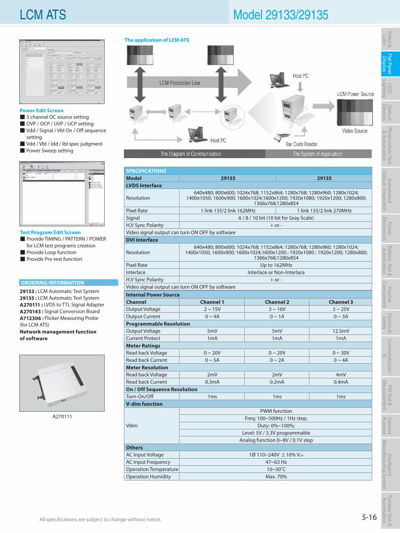
5-16All specifications are subject to change without notice. All specifications are subject to change without notice.
Flat PanelD
isplayPow
er Electronics
Electrical Safety
General
PurposePassive
Component
Semiconductor/
ICBattery Test & Autom
ationAutom
atedO
ptical Inspection Photovoltaic Test
& Automation
PXI Test &
Measurem
ent Video & Color
LED/
LightingO
ptical D
evicesIntelligent
Manufacturing System
Turnkey Test & Autom
ation LCM ATS Model 29133/29135
Test Program Edit Screen Provide TIMING / PATTERN / POWER for LCM test programs creation Provide Loop function Provide Pre-test function
29133 : LCM Automatic Test System29135 : LCM Automatic Test SystemA270111 : LVDS to TTL Signal AdapterA270143 : Signal Conversion BoardA712306 : Flicker Measuring Probe(for LCM ATS)Network management functionof software
Power Edit Screen 3 channel DC source setting OVP / OCP / UVP / UCP setting Vdd / Signal / Vbl On / Off sequence setting Vdd / Vbl / Idd / Ibl spec judgment Power Sweep setting
SPECIFICATIONSModel 29133 29135LVDS Interface
Resolution640x480; 800x600; 1024x768; 1152x864; 1280x768; 1280x960; 1280x1024;
1400x1050; 1600x900; 1600x1024;1600x1200; 1920x1080; 1920x1200; 1280x800; 1366x768;1280x854
Pixel Rate 1 link 135/2 link 162MHz 1 link 135/2 link 270MHzSignal 6 / 8 / 10 bit (10 bit for Gray Scale)H,V Sync Polarity + or -Video signal output can turn ON OFF by softwareDVI Interface
Resolution640x480; 800x600; 1024x768; 1152x864; 1280x768; 1280x960; 1280x1024;
1400x1050; 1600x900; 1600x1024;1600x1200 ; 1920x1080 ; 1920x1200; 1280x800; 1366x768;1280x854
Pixel Rate Up to 162MHzInterlace Interlace or Non-InterlaceH,V Sync Polarity + or -Video signal output can turn ON OFF by software
The application of LCM ATS
A270111
Internal Power SourceChannel Channel 1 Channel 2 Channel 3Output Voltage 2 ~ 15V 3 ~ 16V 3 ~ 25VOutput Current 0 ~ 4A 0 ~ 1A 0 ~ 3AProgrammable ResolutionOutput Voltage 5mV 5mV 12.5mVCurrent Protect 1mA 1mA 1mAMeter RatingsRead back Voltage 0 ~ 20V 0 ~ 20V 0 ~ 30VRead back Current 0 ~ 5A 0 ~ 2A 0 ~ 4AMeter ResolutionRead back Voltage 2mV 2mV 4mVRead back Current 0.3mA 0.2mA 0.4mAOn / Off Sequence ResolutionTurn-On/Off 1ms 1ms 1msV-dim function
Vdim
PWM functionFreq: 100~500Hz / 1Hz step;
Duty: 0%~100%;Level: 5V / 3.3V programmable
Analog function 0~8V / 0.1V stepOthersAC Input Voltage 1Ø 110~240V ±10% VLH
AC Input Frequency 47~63 HzOperation Temperature 10~30˚COperation Humidity Max. 70%
ORDERING INFORMATION
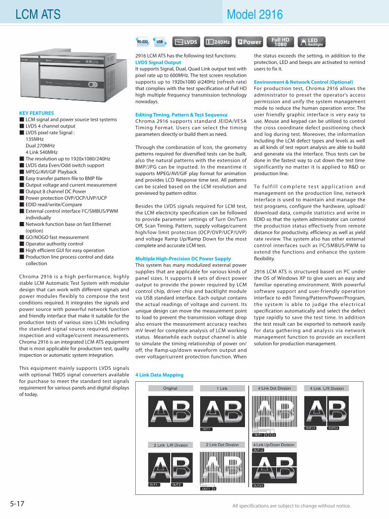
5-17 All specifications are subject to change without notice. All specifications are subject to change without notice.
LCM ATS Model 2916
KEY FEATURES LCM signal and power source test systems LVDS 4 channel output LVDS pixel rate Signal : 135MHz Dual 270MHz 4 Link 540MHz The resolution up to 1920x1080/240Hz LVDS data Even/Odd switch support MPEG/AVI/GIF Playback Easy transfer pattern file to BMP file Output voltage and current measurement Output 8 channel DC Power Power protection OVP/OCP/UVP/UCP EDID read/write/Compare External control interface I2C/SMBUS/PWM individually Network function base on fast Ethernet (option) GO/NOGO fast measurement Operator authority control High efficient GUI for easy operation Production line process control and data collection
Chroma 2916 is a high per formance, highly stable LCM Automatic Test System with modular design that can work with different signals and power modules flexibly to compose the test conditions required. It integrates the signals and power source with powerful network function and friendly interface that make it suitable for the production tests of various sizes LCMs including the standard signal source required, pattern inspection and voltage/current measurements. Chroma 2916 is an integrated LCM ATS equipment that is most applicable for production test, quality inspection or automatic system integration.
This equipment mainly supports LVDS signals with optional TMDS signal converters available for purchase to meet the standard test signals requirement for various panels and digital displays of today.
2916 LCM ATS has the following test functions:LVDS Signal OutputIt supports Signal, Dual, Quad Link output test with pixel rate up to 600MHz. The test screen resolution supports up to 1920x1080 @240Hz (refresh rate) that complies with the test specification of Full HD high multiple frequency transmission technology nowadays.
Editing Timing, Pattern & Test SequenceChroma 2916 supports standard JEIDA/VESA Timing Format. Users can select the timing parameters directly or build them as need.
Through the combination of Icon, the geometry patterns required for diversified tests can be built, also the natural patterns with the extension of BMP/JPG can be inputted. In the meantime it supports MPEG/AVI/GIF play format for animation and provides LCD Response time test. All patterns can be scaled based on the LCM resolution and previewed by pattern editor.
Besides the LVDS signals required for LCM test, the LCM electricity specification can be followed to provide parameter settings of Turn On/Turn Off, Scan Timing, Pattern, supply voltage/current high/low limit protection (OCP/OVP/UCP/UVP) and voltage Ramp Up/Ramp Down for the most complete and accurate LCM test.
Multiple High-Precision DC Power SupplyThis system has many modulized external power supplies that are applicable for various kinds of panel sizes. It supports 8 sets of direct power output to provide the power required by LCM control chip, driver chip and backlight module via USB standard interface. Each output contains the actual readings of voltage and current. Its unique design can move the measurement point to load to prevent the transmission voltage drop also ensure the measurement accuracy reaches mV level for complete analysis of LCM working status. Meanwhile each output channel is able to simulate the timing relationship of power on/off, the Ramp-up/down waveform output and over voltage/current protection function. When
the status exceeds the setting, in addition to the protection, LED and beeps are activated to remind users to fix it.
Environment & Network Control (Optional)For production test, Chroma 2916 allows the administrator to preset the operator's access permission and unify the system management mode to reduce the human operation error. The user friendly graphic interface is very easy to use. Mouse and keypad can be utilized to control the cross coordinate defect positioning check and log during test. Moreover, the information including the LCM defect types and levels as well as all kinds of test report analysis are able to build and generate via the interface. Thus tests can be done in the fastest way to cut down the test time significantly no matter it is applied to R&D or production line.
To f u l f i l l c o m p l e t e t e s t a p p l i c a t i o n a n d management on the production line, network interface is used to maintain and manage the test programs, configure the hardware, upload/download data, compile statistics and write in EDID so that the system administrator can control the production status effectively from remote distance for productivity, efficiency as well as yield rate review. The system also has other external control interfaces such as I2C/SMBUS/PWM to extend the functions and enhance the system flexibility.
2916 LCM ATS is structured based on PC under the OS of Windows XP to give users an easy and familiar operating environment. With powerful software support and user-friendly operation interface to edit Timing/Pattern/Power/Program, the system is able to judge the e lec tr ica l specification automatically and select the defect type rapidly to save the test time. In addition the test result can be exported to network easily for data gathering and analysis via network management function to provide an excellent solution for production management.
4 Link Data Mapping
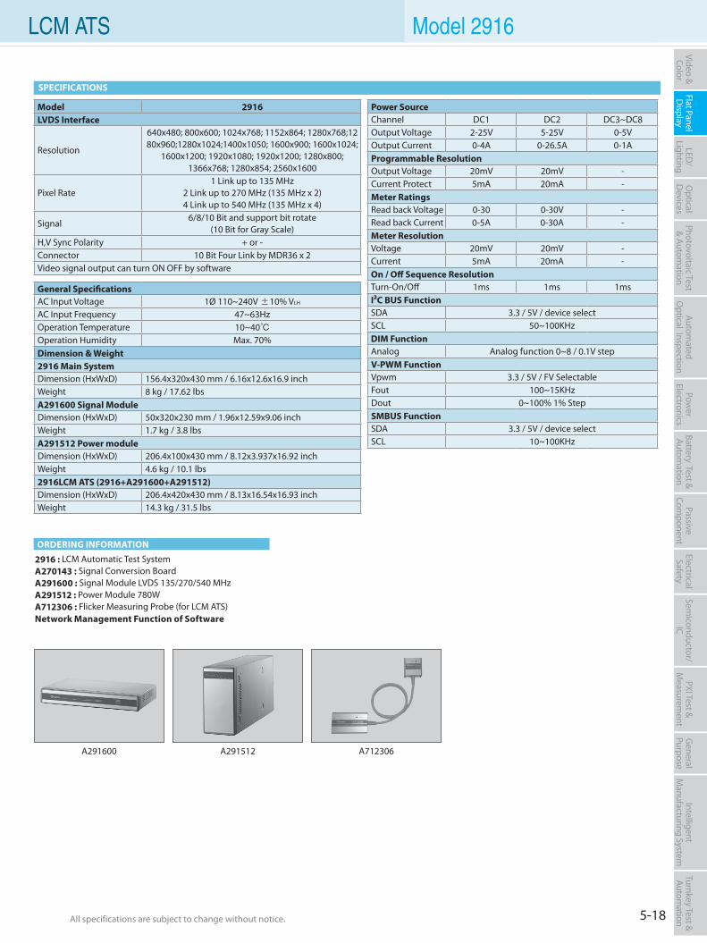
5-18All specifications are subject to change without notice. All specifications are subject to change without notice.
Flat PanelD
isplayPow
er Electronics
Electrical Safety
General
PurposePassive
Component
Semiconductor/
ICBattery Test & Autom
ationAutom
atedO
ptical Inspection Photovoltaic Test
& Automation
PXI Test &
Measurem
ent Video & Color
LED/
LightingO
ptical D
evicesIntelligent
Manufacturing System
Turnkey Test & Autom
ation LCM ATS Model 2916
2916 : LCM Automatic Test SystemA270143 : Signal Conversion BoardA291600 : Signal Module LVDS 135/270/540 MHzA291512 : Power Module 780WA712306 : Flicker Measuring Probe (for LCM ATS)Network Management Function of Software
SPECIFICATIONS
ORDERING INFORMATION
A291600 A291512 A712306
Model 2916LVDS Interface
Resolution
640x480; 800x600; 1024x768; 1152x864; 1280x768;1280x960;1280x1024;1400x1050; 1600x900; 1600x1024;
1600x1200; 1920x1080; 1920x1200; 1280x800; 1366x768; 1280x854; 2560x1600
Pixel Rate1 Link up to 135 MHz
2 Link up to 270 MHz (135 MHz x 2)4 Link up to 540 MHz (135 MHz x 4)
Signal 6/8/10 Bit and support bit rotate
(10 Bit for Gray Scale)H,V Sync Polarity + or -Connector 10 Bit Four Link by MDR36 x 2Video signal output can turn ON OFF by software
General SpecificationsAC Input Voltage 1Ø 110~240V ±10% VLH
AC Input Frequency 47~63HzOperation Temperature 10~40Operation Humidity Max. 70%Dimension & Weight2916 Main SystemDimension (HxWxD) 156.4x320x430 mm / 6.16x12.6x16.9 inchWeight 8 kg / 17.62 lbsA291600 Signal ModuleDimension (HxWxD) 50x320x230 mm / 1.96x12.59x9.06 inchWeight 1.7 kg / 3.8 lbsA291512 Power moduleDimension (HxWxD) 206.4x100x430 mm / 8.12x3.937x16.92 inchWeight 4.6 kg / 10.1 lbs2916LCM ATS (2916+A291600+A291512)Dimension (HxWxD) 206.4x420x430 mm / 8.13x16.54x16.93 inchWeight 14.3 kg / 31.5 lbs
Power SourceChannel DC1 DC2 DC3~DC8Output Voltage 2-25V 5-25V 0-5VOutput Current 0-4A 0-26.5A 0-1AProgrammable ResolutionOutput Voltage 20mV 20mV -Current Protect 5mA 20mA -Meter RatingsRead back Voltage 0-30 0-30V -Read back Current 0-5A 0-30A -Meter ResolutionVoltage 20mV 20mV -Current 5mA 20mA -On / Off Sequence ResolutionTurn-On/Off 1ms 1ms 1msI²C BUS FunctionSDA 3.3 / 5V / device selectSCL 50~100KHzDIM FunctionAnalog Analog function 0~8 / 0.1V stepV-PWM FunctionVpwm 3.3 / 5V / FV SelectableFout 100~15KHzDout 0~100% 1% StepSMBUS FunctionSDA 3.3 / 5V / device selectSCL 10~100KHz
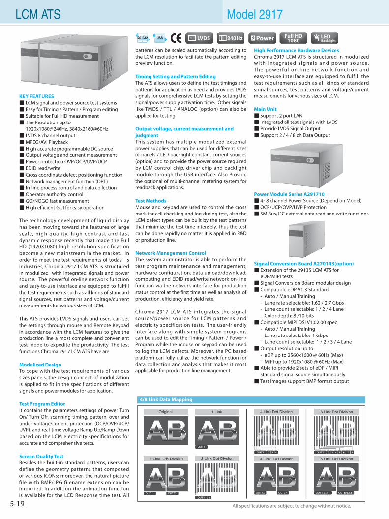
5-19 All specifications are subject to change without notice. All specifications are subject to change without notice.
LCM ATS Model 2917
KEY FEATURES LCM signal and power source test systems Easy for Timing / Pattern / Program editing Suitable for Full HD measurement The Resolution up to 1920x1080@240Hz, 3840x2160@60Hz LVDS 8 channel output MPEG/AVI Playback High accurate programmable DC source Output voltage and current measurement Power protection OVP/OCP/UVP/UCP EDID read/write Cross coordinate defect positioning function Network management function (OPT) In-line process control and data collection Operator authority control GO/NOGO fast measurement High efficient GUI for easy operation
The technology development of liquid display has been moving toward the features of large scale, high qual ity, high contrast and fast dynamic response recently that made the Full HD (1920X1080) high resolution specification become a new mainstream in the market. In order to meet the test requirements of today’s industries, Chroma 2917 LCM ATS is structured in modulized with integrated signals and power source. The powerful on-line network function and easy-to-use interface are equipped to fulfill the test requirements such as all kinds of standard signal sources, test patterns and voltage/current measurements for various sizes of LCM.
This ATS provides LVDS signals and users can set the settings through mouse and Remote Keypad in accordance with the LCM features to give the production line a most complete and convenient test mode to expedite the productivity. The test functions Chroma 2917 LCM ATS have are:
Modulized DesignTo cope with the test requirements of various sizes panels, the design concept of modulization is applied to fit in the specifications of different signals and power modules for application.
Test Program EditorIt contains the parameters settings of power Turn On/ Turn Off, scanning timing, pattern, over and under voltage/current protection (OCP/OVP/UCP/UVP), and real-time voltage Ramp Up/Ramp Down based on the LCM electricity specifications for accurate and comprehensive tests.
Screen Quality TestBesides the built-in standard patterns, users can define the geometry patterns that composed of various ICONs; moreover, the natural picture file with BMP/JPG filename extension can be imported. In addition the animation function is available for the LCD Response time test. All
patterns can be scaled automatically according to the LCM resolution to facilitate the pattern editing preview function.
Timing Setting and Pattern Editing The ATS allows users to define the test timings and patterns for application as need and provides LVDS signals for comprehensive LCM tests by setting the signal/power supply activation time. Other signals like TMDS / TTL / ANALOG (option) can also be applied for testing.
Output voltage, current measurement and judgmentThis system has multiple modulized external power supplies that can be used for different sizes of panels / LED backlight constant current sources (option) and to provide the power source required by LCM control chip, driver chip and backlight module through the USB interface. Also Provide the optional of multi-channel metering system for readback applications.
Test MethodsMouse and keypad are used to control the cross mark for cell checking and log during test, also the LCM defect types can be built by the test patterns that minimize the test time intensely. Thus the test can be done rapidly no matter it is applied in R&D or production line.
Network Management Control The system administrator is able to perform the test program maintenance and management, hardware configuration, data upload/download, computing and EDID read/write network on-line function via the network interface for production status control at the first time as well as analysis of production, efficiency and yield rate.
Chroma 2917 LCM ATS integrates the signal source/power source for LCM patterns and electricity specification tests. The user-friendly interface along with simple system programs can be used to edit the Timing / Pattern / Power / Program while the mouse or keypad can be used to log the LCM defects. Moreover, the PC based platform can fully utilize the network function for data collection and analysis that makes it most applicable for production line management.
High Performance Hardware DevicesChroma 2917 LCM ATS is structured in modulized w i t h i n te gra te d s i gn a l s a n d p owe r s o u rce. The power ful on-l ine net work func t ion and easy-to-use interface are equipped to fulfill the test requirements such as all kinds of standard signal sources, test patterns and voltage/current measurements for various sizes of LCM.
Main Unit Support 2 port LAN Integrated all test signals with LVDS Provide LVDS Signal Output Support 2 / 4 / 8 ch Data Output
Power Module Series A291710 4~8 channel Power Source (Depend on Model) OCP/UCP/OVP/UVP Protection SM Bus, I2 C external data read and write functions
Signal Conversion Board A270143(option) Extension of the 29135 LCM ATS for eDP/MIPI tests Signal Conversion Board modular design Compatible eDP V1.3 Standard - Auto / Manual Training - Lane rate selectable: 1.62 / 2.7 Gbps - Lane count selectable: 1 / 2 / 4 Lane - Color depth: 8 /10 bits Compatible MIPI DSI V1.02.00 spec - Auto / Manual Training - Lane rate selectable: 1 Gbps - Lane count selectable: 1 / 2 / 3 / 4 Lane Output resolution up to - eDP up to 2560x1600 @ 60Hz (Max) - MIPI up to 1920x1080 @ 60Hz (Max) Able to provide 2 sets of eDP / MIPI standard signal source simultaneously Test images support BMP format output
4/8 Link Data Mapping
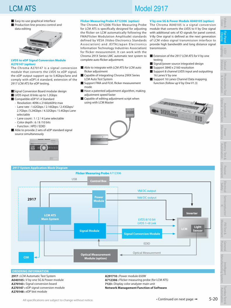
5-20All specifications are subject to change without notice. All specifications are subject to change without notice.
Flat PanelD
isplayPow
er Electronics
Electrical Safety
General
PurposePassive
Component
Semiconductor/
ICBattery Test & Autom
ationAutom
atedO
ptical Inspection Photovoltaic Test
& Automation
PXI Test &
Measurem
ent Video & Color
LED/
LightingO
ptical D
evicesIntelligent
Manufacturing System
Turnkey Test & Autom
ation LCM ATS Model 2917
• Continued on next page
2917 System Application Block Diagram
2917 : LCM Automatic Test SystemA040105 : V by one SG & Power moduleA270143 : Signal conversion boardA270147 : eDP signal conversion moduleA270148 : eDP bist module
A291710 : Power module 650WA712306 : Flicker measuring probe (for LCM ATS)7123 : Display color analyzer main unitNetwork Management Function of Software
ORDERING INFORMATION
CIMOptical Measurement
Module (option)
Inverter
Vbl DC output
Vdd DC output
EDID
LVDS 8/10 bitLVDS 1~8 Link
LCM ATSMain System
Power Module
Signal Module
USB
Optical Measurement
2917
Control Box
Flicker Measuring Probe A712306
LightSensorLCM
Signal Conversion Module
Easy-to-use graphical interface Production line process control and data editing
V by one SG & Power Module A040105 (option)The Chroma A040105 is a signal conversion module that converts the LVDS to V by One signal with additional sets of IO signals for panel control. V-By One signal is defined as the next generation of LCM video signal transmission interface to provide high bandwidth and long distance signal transmission.
Extension of the 2917 LCM ATS for V by one testing Signal/power source integrated design Support 3840 x 2160 resolution Support 8 channel LVDS input and outputting 16 Lanes V by one Support 16 Lanes Channel Data mapping function (follow up V by One V1.3)
Flicker Measuring Probe A712306 (option)The Chroma A712306 Flicker Measuring Probe for LCM ATS is specifically designed for adjusting the flicker on LCM automatically following the FMA(Flicker Modulation Amplitude) standards defined by VESA (Video Electronics Standards A s s o c i a t i o n) a n d J E I TA(J a p a n E l e c t ro n i c s Information Technology Industries Association) for flicker measurement. It can work with the Chroma 291X Series LMC automatic test system to complete auto flicker adjustment.
Able to integrate with LCM ATS for LCM auto flicker adjustment Capable of integrating Chroma 29XX Series LCM Auto Test System Support FMA and FLVL flicker measurement mode Have a patented adjustment algorithm, making adjustment speed faster Capable of editing adjustment script when using with LCM Master
LVDS to eDP Signal Conversion ModuleA270147 (option)The Chroma A270147 is a signal conversion module that converts the LVDS to eDP signal, the eDP output support up to 5.4Gbps/lane and comply with eDP1.4 standard, extension of the 2917 LCM ATS for eDP testing.
Signal Conversion Board modular design LVDS input: 8 links up to 1.2Gbps Compatible eDP V1.4 Standard - Resolution: 4096 x 2160@60Hz max - Lane rate : 1.62Gbps / 2.16Gbps / 2.43Gbps/ 2.7Gbps /3.24Gbps / 4.32Gbps / 5.4Gbps Lane selectable - Lane count : 1 / 2 / 4 Lane selectable - Color depth : 6 / 8 /10 bits - Function : HPD / EDID Able to provide 2 sets of eDP standard signal source simultaneously
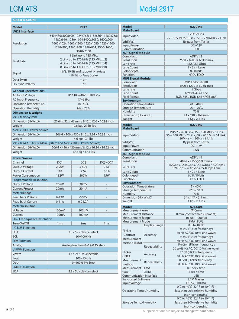
5-21 All specifications are subject to change without notice. All specifications are subject to change without notice.
LCM ATS Model 2917SPECIFICATIONS
Power SourceChannel DC1 DC2 DC3~DC4Output Voltage 2-20V 5-50V 0-5VOutput Current 10A 22A 0-1APower Consumption 132W 500W 15WProgrammable ResolutionOutput Voltage 20mV 20mV -Current Protect 20mA 20mA -Meter RatingsRead back Voltage 0-22V 0-55V -Read back Current 0-11A 0-24.2A -Meter ResolutionVoltage 100mV 100mV -Current 100mA 100mA -On / Off Sequence ResolutionTurn-On/Off 1ms 1ms 1msI2C BUS FunctionSDA 3.3 / 5V / device selectSCL 50~100KHzDIM FunctionAnalog Analog function 0~12/0.1V stepV-PWM FunctionVpwm 3.3 / 5V / FV SelectableFout 100~15KHzDout 0~100% 1% StepSMBUS FunctionSDA 3.3 / 5V / device select
Model A270147Main Board
Input VideoLVDS 2 / 4 / 8 Link, 15 ~ 150 MHz / 1 Link,
30 ~ 300 MHz / 2 Link, 60 ~ 600 MHz / 4 Link, 20MHz ~ 1.2GHz / 8 Link
Vdd(Vcc) By pass from Tester Input Power DC +12VCommunication LANeDP Signal ModuleCompliant eDP V1.4Resolution 4096 x 2160@60Hz max
Lane rate 1.62Gbps / 2.16Gbps / 2.43Gbps / 2.7Gbps / 3.24Gbps / 4.32Gbps / 5.4Gbps Lane
Lane Count 1 / 2 / 4 LaneColor depth 6 / 8 /10 bitsFunction HPD / EDIDEnvironmentOperation Temperature 5~ 40 Storage Temperature -20 ~ 60Humidity 70%Dimension (H x W x D) 34 x 147 x 211 mmWeight 1 Kg / 2.2 lbs
Model A270143Main Board
Input VideoLVDS 2 Link
25 ~ 135 MHz / 1 Link ; 50 ~ 270 MHz / 2 LinkVdd(Vcc) By pass from TesterInput Power DC +12VCommunication USBeDP Signal ModuleCompliant eDP V1.3Resolution 2560 x 1600 @ 60 Hz maxLane rate 1.62 / 2.7 GbpsLane Count 1 / 2 / 4 LaneColor depth 8 /10 bitsFunction HPD / EDIDMIPI Signal ModuleCompliant MIPI DSI V1.02.00Resolution 1920 x 1200 @ 60 Hz maxLane rate 1 GbpsLane Count 1/2/3/4/4+4 LanePixel format RGB-565 / RGB-666 / RGB-888EnvironmentOperation Temperature 20 ~ 40Storage Temperature -20 ~ 70Humidity 70%Dimension (H x W x D) 43 x 190 x 164 mmWeight 1 Kg / 2.2 lbs
Model 2917LVDS Interface
Resolution
640x480; 800x600; 1024x768; 1152x864; 1280x768;1280x960; 1280x1024;1400x1050; 1600x900;
1600x1024; 1600x1200; 1920x1080; 1920x1200; 1280x800; 1366x768; 1280x854; 2560x1600;
3840x2160
Pixel Rate
1 Link up to 135 MHz2 Link up to 270 MHz (135 MHz x 2)4 Link up to 540 MHz (135 MHz x 4)8 Link up to 1.08GHz ( 135 Mhz x 8)
Signal 6/8/10 Bit and support bit rotate (10 Bit for Gray Scale)
Data Swap + or -H,V Sync Polarity + or -
General SpecificationsAC Input Voltage 1Ø 110~240V ±10% VLH
AC Input Frequency 47~63HzOperation Temperature 10~40Operation Humidity Max. 70%Dimension & Weight2917 Main SystemDimension (HxWxD) 20.64 x 32 x 43 mm / 8.12 x 12.6 x 16.92 inchWeight 12.6 kg / 27lbs lbsA291710 DC Power SourceDimension (HxWxD) 206.4 x 100 x 430 / 8.12 x 3.94 x 16.92 inchWeight 4.6 kg/10.1 lbs2917 LCM ATS (2917 Main System and A291710 DC Power Source)Dimension (HxWxD) 206.4 x 420 x 430 mm / 8.12 x 16.54 x 16.92 inchWeight 17.2 kg / 37.1 lbs
Model A712306Measurement Area Ø10mmMeasurement Distance 0 mm (contact measurement)Measurement Range 10 lux ~1000luxMeasurement Mode FMA , FLVL
Flicker-ContrastMeasurementmethod (FMA)
Display Range 0.0 to 100%
Accuracy
±2% (Flicker frequency : 30 Hz AC/DC 10 % sine wave)±3% (Flicker frequency :
60 Hz AC/DC 10 % sine wave)
Repeatability1% (2σ) (Flicker frequency :
20 to 65 Hz AC/DC 10 % sine wave)Flicker-JEITAMeasurementmethod
Accuracy ±1dB (Flicker frequency : 30 Hz AC/DC 10 % sine wave)
Repeatability0.5dB (Flicker frequency :
30 Hz AC/DC 10 % sine wave)Measurement time
FMA 0.5 sec / timeJEITA 2 sec / time
Communication Interface USBSupported Software LCM MasterInput Voltage DC 5V, 500 mA
Operating Temp./Humidity 0˚C to 40˚C (32°F to 104°F) ;
less than 90% relative humidity(non-condensing)
Storage Temp./Humidity0˚C to 40˚C (32°F to 104°F) ;
less then 90% relative humidity(non-condensing)
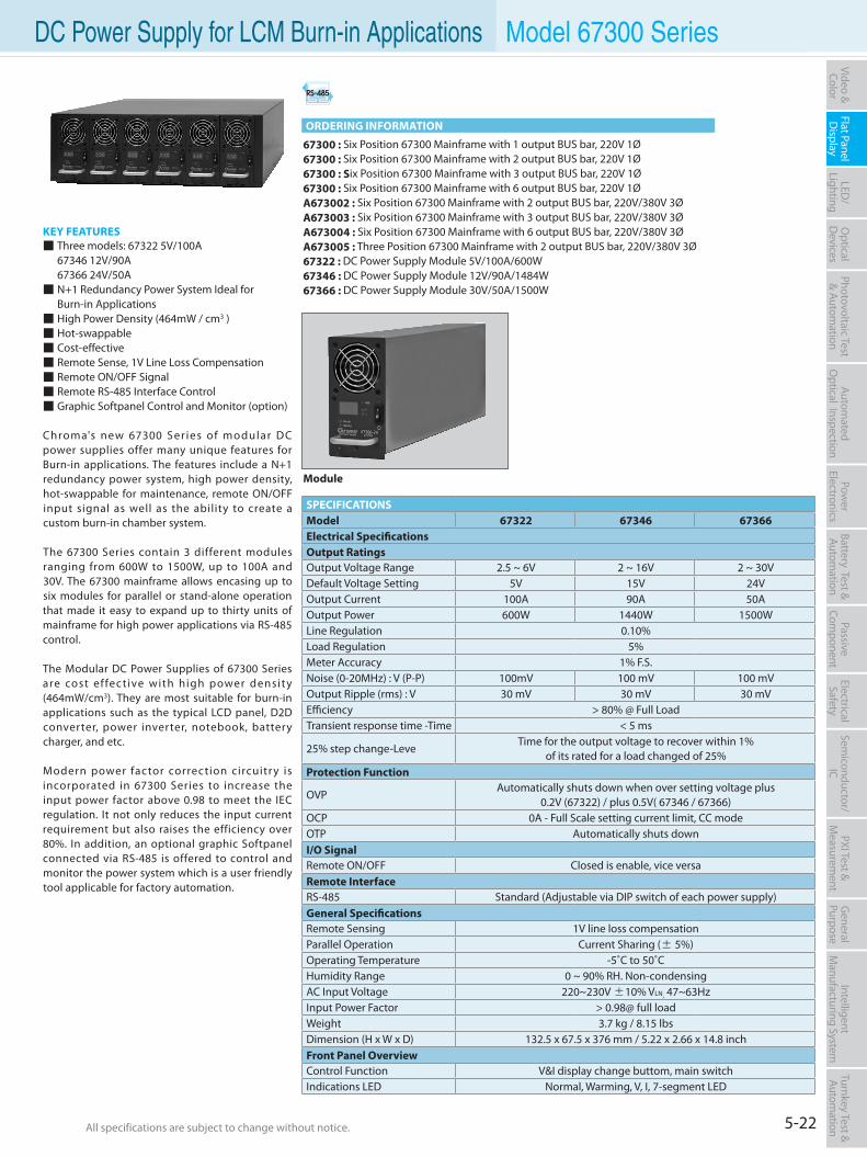
5-22All specifications are subject to change without notice. All specifications are subject to change without notice.
Flat PanelD
isplayPow
er Electronics
Electrical Safety
General
PurposePassive
Component
Semiconductor/
ICBattery Test & Autom
ationAutom
atedO
ptical Inspection Photovoltaic Test
& Automation
PXI Test &
Measurem
ent Video & Color
LED/
LightingO
ptical D
evicesIntelligent
Manufacturing System
Turnkey Test & Autom
ation DC Power Supply for LCM Burn-in Applications Model 67300 Series
KEY FEATURES Three models: 67322 5V/100A 67346 12V/90A 67366 24V/50A N+1 Redundancy Power System Ideal for Burn-in Applications High Power Density (464mW / cm3 ) Hot-swappable Cost-effective Remote Sense, 1V Line Loss Compensation Remote ON/OFF Signal Remote RS-485 Interface Control Graphic Softpanel Control and Monitor (option)
Chroma's new 67300 Ser ies of modular DC power supplies offer many unique features for Burn-in applications. The features include a N+1 redundancy power system, high power density, hot-swappable for maintenance, remote ON/OFF input signal as well as the ability to create a custom burn-in chamber system.
The 67300 Series contain 3 different modules ranging from 600W to 1500W, up to 100A and 30V. The 67300 mainframe allows encasing up to six modules for parallel or stand-alone operation that made it easy to expand up to thirty units of mainframe for high power applications via RS-485 control.
The Modular DC Power Supplies of 67300 Series are cost effective with high power density (464mW/cm3). They are most suitable for burn-in applications such as the typical LCD panel, D2D converter, power inverter, notebook, battery charger, and etc.
Modern power factor correction circuitry is incorporated in 67300 Series to increase the input power factor above 0.98 to meet the IEC regulation. It not only reduces the input current requirement but also raises the efficiency over 80%. In addition, an optional graphic Softpanel connected via RS-485 is offered to control and monitor the power system which is a user friendly tool applicable for factory automation.
67300 : Six Position 67300 Mainframe with 1 output BUS bar, 220V 1Ø67300 : Six Position 67300 Mainframe with 2 output BUS bar, 220V 1Ø67300 : Six Position 67300 Mainframe with 3 output BUS bar, 220V 1Ø67300 : Six Position 67300 Mainframe with 6 output BUS bar, 220V 1ØA673002 : Six Position 67300 Mainframe with 2 output BUS bar, 220V/380V 3ØA673003 : Six Position 67300 Mainframe with 3 output BUS bar, 220V/380V 3ØA673004 : Six Position 67300 Mainframe with 6 output BUS bar, 220V/380V 3ØA673005 : Three Position 67300 Mainframe with 2 output BUS bar, 220V/380V 3Ø67322 : DC Power Supply Module 5V/100A/600W67346 : DC Power Supply Module 12V/90A/1484W67366 : DC Power Supply Module 30V/50A/1500W
SPECIFICATIONSModel 67322 67346 67366Electrical SpecificationsOutput RatingsOutput Voltage Range 2.5 ~ 6V 2 ~ 16V 2 ~ 30VDefault Voltage Setting 5V 15V 24VOutput Current 100A 90A 50AOutput Power 600W 1440W 1500WLine Regulation 0.10%Load Regulation 5%Meter Accuracy 1% F.S.Noise (0-20MHz) : V (P-P) 100mV 100 mV 100 mVOutput Ripple (rms) : V 30 mV 30 mV 30 mVEfficiency > 80% @ Full LoadTransient response time -Time < 5 ms
25% step change-Leve Time for the output voltage to recover within 1%
of its rated for a load changed of 25%Protection Function
OVP Automatically shuts down when over setting voltage plus
0.2V (67322) / plus 0.5V( 67346 / 67366)OCP 0A - Full Scale setting current limit, CC modeOTP Automatically shuts downI/O SignalRemote ON/OFF Closed is enable, vice versaRemote InterfaceRS-485 Standard (Adjustable via DIP switch of each power supply)General SpecificationsRemote Sensing 1V line loss compensationParallel Operation Current Sharing (± 5%)Operating Temperature -5˚C to 50˚CHumidity Range 0 ~ 90% RH. Non-condensingAC Input Voltage 220~230V ±10% VLN, 47~63HzInput Power Factor > 0.98@ full loadWeight 3.7 kg / 8.15 lbsDimension (H x W x D) 132.5 x 67.5 x 376 mm / 5.22 x 2.66 x 14.8 inchFront Panel OverviewControl Function V&I display change buttom, main switchIndications LED Normal, Warming, V, I, 7-segment LED
Module
ORDERING INFORMATION
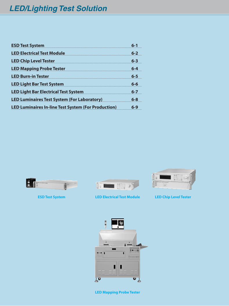
LED/Lighting Test Solution
ESD Test System
LED Mapping Probe Tester
LED Electrical Test Module LED Chip Level Tester
ESD Test System 6-1
LED Electrical Test Module 6-2
LED Chip Level Tester 6-3
LED Mapping Probe Tester 6-4
LED Burn-in Tester 6-5
LED Light Bar Test System 6-6
LED Light Bar Electrical Test System 6-7
LED Luminaires Test System (For Laboratory) 6-8
LED Luminaires In-line Test System (For Production) 6-9
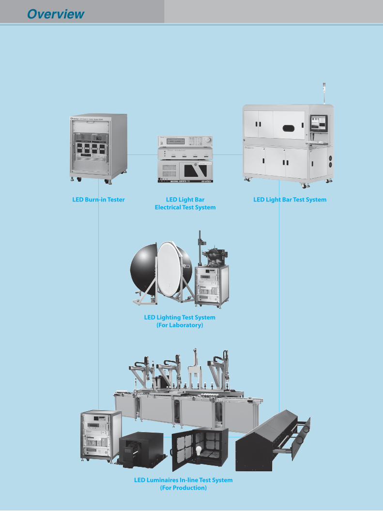
Overview
LED Light Bar Test SystemLED Light BarElectrical Test System
LED Lighting Test System(For Laboratory)
LED Burn-in Tester
LED Luminaires In-line Test System(For Production)
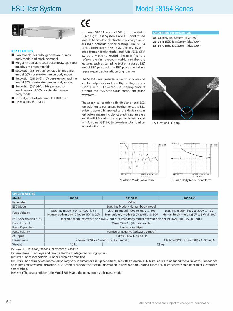
6-1 All specifications are subject to change without notice. All specifications are subject to change without notice.
ESD Test System Model 58154 Series
C h ro m a 58154 s e r i e s E S D (E l e c t ro s t a t i c Discharge) Test Systems are PCI controlled module to simulate electrostatic discharge pulse during electronic device testing. The 58154 series offer both ANSI/ESDA/JEDEC JS-001-2014-Human Body Model and ANSI/ESD STM 5.2-2012-Machine Model. The user friendly software offers programmable and flexible features, such as sampling test on a wafer, ESD model, ESD pulse polarity, ESD pulse interval in a sequence, and automatic testing function.
The 58154 series includes a control module and a pulse output external box. High voltage power supply unit (PSU) and pulse shaping circuits provide the ESD standards compliant pulse waveform.
The 58154 series offer a flexible and total ESD test solution to customers. Furthermore, the ESD pulse is generally applied to the device under test before measuring device electric parameters and the 58154 series can be perfectly integrated with Chroma 58212-C to provide a total solution in production line.
KEY FEATURES Two models ESD pulse generation : human
body model and machine model Programmable auto test : pulse delay, cycle and
polarity are programmable Resolution (58154) : 5V per-step for machine
model, 20V per-step for human body model Resolution (58154-B) : 10V per-step for machine
model, 30V per-step for human body model Resolution (58154-C) : 10V per-step for
machine model, 30V per-step for human body model Diversity control interface : PCI DIO card Up to 8000V (58154-C)
58154 : ESD Test System (4kV/400V)58154-B : ESD Test System (6kV/800V)58154-C : ESD Test System (8kV/800V)
ESD Test on LED chip
ORDERING INFORMATION
Machine Model waveform Human Body Model waveform
SPECIFICATIONSModel 58154 58154-B 58154-CParameter ValueESD Mode Machine Model / Human body model
Pulse VoltageMachine model: 50V to 400V ± 5V
Human body model: 250V to 4KV ± 20VMachine model: 100V to 800V ± 10V
Human body model: 250V to 6KV ± 30VMachine model: 100V to 800V ± 10V
Human body model: 250V to 8KV ± 30VESD Specification *1 *2 Machine model reference on STM5.2-2012 ; Human body model reference on ANSI/ESDA/JEDEC JS-001-2014Pulse Interval 20 ms *3 to 1 s (User definable)Pulse Repetition Single or multiplePulse Polarity Positive or negative (software control)AC Input 100 to 240V, 47 to 63 HzDimensions 434.6mm(W) x 97.7mm(H) x 306.8mm(D) 434.6mm(W) x 97.7mm(H) x 450mm(D)Weight 10 kg 12 kg
Pattern No. : I311648, I398655, ZL 2009 2 0148342.2Pattern Name : Discharge and remote feedback integrated testing systemNote*1 : The test condition is under Chroma's probe tipsNote*2 : The accuracy of Chroma 58154 may vary in customer's setup conditions. To fix this problem, ESD tester needs to be tuned the value of the impedance to minimized waveform distortion, or customers provide their setup information in advance and Chroma tunes ESD testers before shipment to fit customer's test method.Note*3 : The test condition is for Model 58154 and the operation is at fix pulse mode.
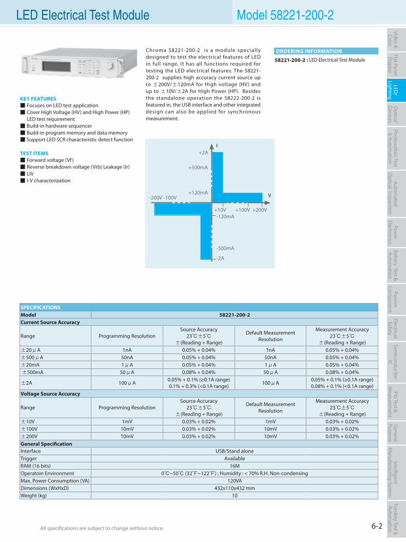
6-2All specifications are subject to change without notice. All specifications are subject to change without notice.
Flat PanelD
isplayPow
er Electronics
Electrical Safety
General
PurposePassive
Component
Semiconductor/
ICBattery Test & Autom
ationAutom
atedO
ptical Inspection Photovoltaic Test
& Automation
PXI Test &
Measurem
ent Video & Color
LED/
LightingO
ptical D
evicesIntelligent
Manufacturing System
Turnkey Test & Autom
ation LED Electrical Test Module Model 58221-200-2
58221-200-2 : LED Electrical Test Module
ORDERING INFORMATION
KEY FEATURES Focuses on LED test application Cover High Voltage (HV) and High Power (HP) LED test requirement Build-in hardware sequencer Build-in program memory and data memory Support LED SCR characteristic detect function
TEST ITEMS Forward voltage (Vf ) Reverse breakdown voltage (Vrb) Leakage (Ir) LIV I-V characterization
Chroma 58221-200-2 is a module specially designed to test the electrical features of LED in full range. It has all functions required for testing the LED electrical features. The 58221-200-2 supplies high accuracy current source up to ±200V/±120mA for High voltage (HV) and up to ±10V/±2A for High Power (HP). Besides the standalone operation the 58222-200-2 is featured in, the USB interface and other integrated design can also be applied for synchronous measurement.
+2A
+10V +100V +200V-10V
+500mA
+120mA
-500mA
-2A
-120mA
-200V -100V V
I
SPECIFICATIONSModel 58221-200-2Current Source Accuracy
Range Programming ResolutionSource Accuracy
23±5 ±(Reading + Range)
Default Measurement Resolution
Measurement Accuracy23±5
±(Reading + Range)±20μA 1nA 0.05% + 0.04% 1nA 0.05% + 0.04%±500μA 50nA 0.05% + 0.04% 50nA 0.05% + 0.04%±20mA 1μA 0.05% + 0.04% 1μA 0.05% + 0.04% ±500mA 50μA 0.08% + 0.04% 50μA 0.08% + 0.04%
±2A 100μA 0.05% + 0.1% (≥0.1A range)0.1% + 0.3% (<0.1A range) 100μA 0.05% + 0.1% (≥0.1A range)
0.08% + 0.1% (<0.1A range)Voltage Source Accuracy
Range Programming ResolutionSource Accuracy
23±5±(Reading + Range)
Default Measurement Resolution
Measurement Accuracy23±5
±(Reading + Range)±10V 1mV 0.03% + 0.02% 1mV 0.03% + 0.02%±100V 10mV 0.03% + 0.02% 10mV 0.03% + 0.02%±200V 10mV 0.03% + 0.02% 10mV 0.03% + 0.02%General SpecificationInterface USB/Stand aloneTrigger AvailableRAM (16 bits) 16MOperatoin Environment 0~50 (32~122) ; Humidity : < 70% R.H. Non-condensingMax. Power Consumption (VA) 120VADimensions (WxHxD) 432x110x432 mmWeight (kg) 10
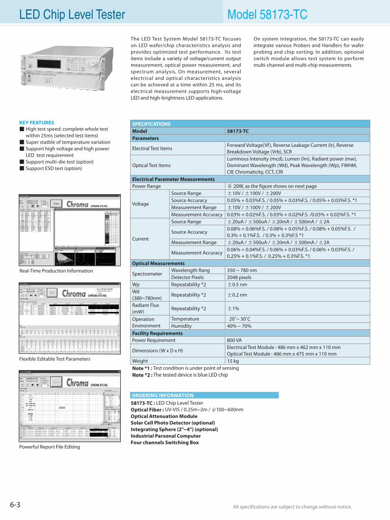
6-3 All specifications are subject to change without notice. All specifications are subject to change without notice.
LED Chip Level Tester Model 58173-TC
58173-TC : LED Chip Level TesterOptical Fiber : UV-VIS / 0.25m~2m / ψ100~600nmOptical Attenuation ModuleSolar Cell Photo Detector (optional)Integrating Sphere (2"~4") (optional)Industrial Personal ComputerFour channels Switching Box
ORDERING INFORMATION
The LED Test System Model 58173-TC focuses on LED wafer/chip characteristics analysis and provides optimized test performance. Its test items include a variety of voltage/current output measurement, optical power measurement, and spectrum analysis. On measurement, several electrical and optical characteristics analysis can be achieved at a time within 25 ms, and its electrical measurement supports high-voltage LED and high-brightness LED applications.
On system integration, the 58173-TC can easily integrate various Probers and Handlers for wafer probing and chip sorting. In addition, optional switch module allows test system to perform multi-channel and multi-chip measurements.
Real-Time Production Information
Flexible Editable Test Parameters
Powerful Report File Editing
KEY FEATURES High test speed: complete whole test within 25ms (selected test items) Super statble of temperature variation Support high voltage and high power LED test requirement Support multi-die test (option) Support ESD test (option)
SPECIFICATIONSModel 58173-TCParameters
Electiral Test ItemsForward Voltage(Vf ), Reverse Leakage Current (Ir), Reverse Breakdown Voltage (Vrb), SCR
Optical Test ItemsLuminous Intensity (mcd), Lumen (lm), Radiant power (mw), Dominant Wavelength (Wd), Peak Wavelength (Wp), FWHM,CIE Chromaticity, CCT, CRI
Electrical Parameter Measurements Power Range ≦ 20W, as the figure shows on next page
Voltage
Source Range ±10V / ±100V / ±200VSource Accuracy 0.05% + 0.03%F.S. / 0.05% + 0.03%F.S. / 0.05% + 0.03%F.S. *1Measurement Range ±10V / ±100V / ±200VMeasurement Accuracy 0.03% + 0.02%F.S. / 0.03% + 0.02%F.S. /0.03% + 0.02%F.S. *1
Current
Source Range ±20uA / ±500uA / ±20mA / ±500mA / ±2A
Source Accuracy0.08% + 0.06%F.S. / 0.08% + 0.05%F.S. / 0.08% + 0.05%F.S. / 0.3% + 0.1%F.S. / 0.3% + 0.3%F.S *1
Measurement Range ±20uA / ±500uA / ±20mA / ±500mA / ±2A
Measurement Accuracy0.06% + 0.04%F.S. / 0.06% + 0.03%F.S. / 0.06% + 0.03%F.S. / 0.25% + 0.1%F.S. / 0.25% + 0.3%F.S. *1
Optical Measurements
SpectrometerWavelength Rang 350 ~ 780 nmDetector Pixels 2048 pixels
Wp Repeatability *2 ±0.5 nmWd (380~780nm)
Repeatability *2 ±0.2 nm
Radiant Flux (mW)
Repeatability *2 ±1%
Operation Environment
Temperature 20˚~ 30˚CHumidity 40% ~ 70%
Facility Requirements Power Requirement 800 VA
Dimensions (W x D x H)Electrical Test Module : 486 mm x 462 mm x 110 mmOptical Test Module : 486 mm x 475 mm x 110 mm
Weight 15 kgNote *1 : Test condition is under point of sensingNote *2 : The tested device is blue LED chip
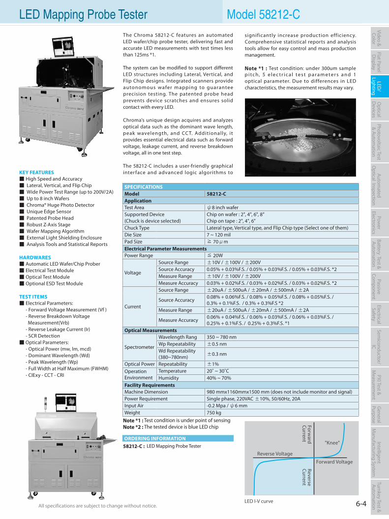
6-4All specifications are subject to change without notice. All specifications are subject to change without notice.
Flat PanelD
isplayPow
er Electronics
Electrical Safety
General
PurposePassive
Component
Semiconductor/
ICBattery Test & Autom
ationAutom
atedO
ptical Inspection Photovoltaic Test
& Automation
PXI Test &
Measurem
ent Video & Color
LED/
LightingO
ptical D
evicesIntelligent
Manufacturing System
Turnkey Test & Autom
ation
58212-C : LED Mapping Probe TesterORDERING INFORMATION
LED Mapping Probe Tester Model 58212-CThe Chroma 58212-C features an automated LED wafer/chip probe tester, delivering fast and accurate LED measurements with test times less than 125ms *1.
The system can be modified to support different LED structures including Lateral, Vertical, and Flip Chip designs. Integrated scanners provide autonomous wafer mapping to guarantee precision testing. The patented probe head prevents device scratches and ensures solid contact with every LED.
Chroma's unique design acquires and analyzes optical data such as the dominant wave length, peak wavelength, and CC T. Additionally, it provides essential electrical data such as forward voltage, leakage current, and reverse breakdown voltage, all in one test step.
The 58212-C includes a user-friendly graphical inter face and advanced logic algorithms to KEY FEATURES
High Speed and Accuracy Lateral, Vertical, and Flip Chip Wide Power Test Range (up to 200V/2A) Up to 8 inch Wafers Chroma® Huge Photo Detector Unique Edge Sensor Patented Probe Head Robust Z-Axis Stage Wafer Mapping Algorithm External Light Shielding Enclosure Analysis Tools and Statistical Reports
HARDWARES Automatic LED Wafer/Chip Prober Electrical Test Module Optical Test Module Optional ESD Test Module
TEST ITEMS Electrical Parameters: - Forward Voltage Measurement (Vf ) - Reverse Breakdown Voltage Measurement(Vrb) - Reverse Leakage Current (Ir) - SCR Detection Optical Parameters: - Optical Power (mw, lm, mcd) - Dominant Wavelength (Wd) - Peak Wavelength (Wp) - Full Width at Half Maximum (FWHM) - CIExy - CCT - CRI
significantly increase production efficiency. Comprehensive statistical reports and analysis tools allow for easy control and mass production management.
Note *1 : Test condition: under 300um sample p i t c h, 5 e l e c t r i c a l t e s t p a r a m e t e r s a n d 1 optical parameter. Due to differences in LED characteristics, the measurement results may vary.
LED I-V curve
Reverse Voltage
Forward Voltage
"Knee"
Forward
CurrentReverse Current
Note *1 : Test condition is under point of sensingNote *2 : The tested device is blue LED chip
SPECIFICATIONSModel 58212-CApplicationTest Area ψ8 inch waferSupported Device (Chuck is device selected)
Chip on wafer : 2", 4", 6", 8"Chip on tape : 2", 4", 6"
Chuck Type Lateral type, Vertical type, and Flip Chip type (Select one of them) Die Size 7 ~ 120 milPad Size ≧ 70μmElectrical Parameter Measurements Power Range ≦ 20W
Voltage
Source Range ±10V / ±100V / ±200VSource Accuracy 0.05% + 0.03%F.S. / 0.05% + 0.03%F.S. / 0.05% + 0.03%F.S. *2Measure Range ±10V / ±100V / ±200VMeasure Accuracy 0.03% + 0.02%F.S. / 0.03% + 0.02%F.S. / 0.03% + 0.02%F.S. *2
Current
Source Range ±20uA / ±500uA / ±20mA / ±500mA / ±2A
Source Accuracy 0.08% + 0.06%F.S. / 0.08% + 0.05%F.S. / 0.08% + 0.05%F.S. / 0.3% + 0.1%F.S. / 0.3% + 0.3%F.S *2
Measure Range ±20uA / ±500uA / ±20mA / ±500mA / ±2A
Measure Accuracy 0.06% + 0.04%F.S. / 0.06% + 0.03%F.S. / 0.06% + 0.03%F.S. / 0.25% + 0.1%F.S. / 0.25% + 0.3%F.S. *1
Optical Measurements
Spectrometer
Wavelength Rang 350 ~ 780 nmWp Repeatability ±0.5 nmWd Repeatability (380~780nm) ±0.3 nm
Optical Power Repeatability ±1%Operation Environment
Temperature 20˚ ~ 30˚CHumidity 40% ~ 70%
Facility Requirements Machine Dimension 980 mmx1160mmx1500 mm (does not include monitor and signal)Power Requirement Single phase, 220VAC ±10%, 50/60Hz, 20AInput Air -0.2 Mpa / ψ6 mmWeight 750 kg
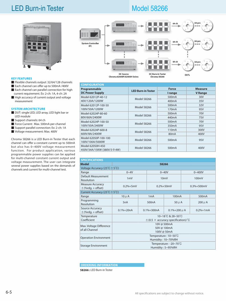
6-5 All specifications are subject to change without notice. All specifications are subject to change without notice.
LED Burn-in Tester Model 58266
KEY FEATURES Flexible channels output: 32/64/128 channels Each channel can offer up to 500mA /400V Each channel can parallel connection for high
current requirement. Ex: 2-ch: 1A, 4-ch: 2A High accuracy of current output and voltage
measurement
SYSTEM ARCHITECTURE DUT: single LED, LED array, LED light bar or LED module Support channels: 64 ch Force Current: Max. 500mA per-channel Support parallel connection: Ex: 2-ch: 1A Voltage measurement: Max. 400V
Chroma 58266 is a LED Burn-in Tester that each channel can offer a constant current up to 500mA but also has 0~400V voltage measurement function. For product application, various programmable power supplies can be applied for multi-channel constant current output and voltage measurement. The user can integrate several power supplies based on the demands of channels and current for multi-channel test.
58266 : LED Burn-in Tester
ORDERING INFORMATION
CONFIGURATIONProgrammableDC Power Supply
LED Burn-in TesterForce Measure
I range V RangeModel 62012P-40-1240V/120A/1200W
Model 58266500mA 30V400mA 35V
Model 62012P-100-50100V/50A/1200W
Model 58266500mA 32V170mA 95V
Model 62024P-80-6080V/60A/2400W
Model 58266500mA 70V440mA 75V
Model 62024P-100-50100V/50A/2400W
Model 58266500mA 70V350mA 95V
Model 62024P-600-8600V/8A/2400W
Model 58266110mA 300V80mA 400V
Model 62050P-100-100100V/100A/5000W
Model 58266 500mA 95V
Model 62050H-450450V/34A/15KW (380V/3Φ4W)
Model 58266 500mA 400V
SPECIFICATIONSModel 58266Voltage Accuracy (23±5)Range 0~4V 0~40V 0~400VDefault Measurement Resolution
1mV 10mV 100mV
Measure Accuracy ±(%rdg. + offset)
0.2%+5mV 0.2%+50mV 0.3%+500mV
Current Accuracy (23±5)Range 10μA 1mA 100mA 500mAProgrammingResolution
5nA 500nA 50μA 200μA
Source Accuracy ±(%rdg. + offset)
0.1%+20nA 0.1%+300nA 0.1%+200μA 0.2%+1mA
TemperatureCoefficient
10~18 & 28~50 ±(0.5 × accuracy specification)/
Max. Voltage Difference of all Channel
10V @ 500mA50V @ 100mA100V @ 50mA
Operation Environment Temperature : 10~50Humidity : 10~70%RH
Storage Environment Temperature : -20~70
Humidity : 5~95%RH
0~4V 0~40V 0~400V
1mV 10mV 100mV
0.2%+5mV 0.2%+50mV 0.3%+500mV
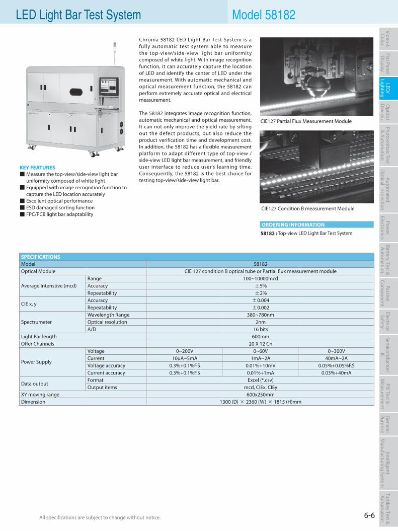
6-6All specifications are subject to change without notice. All specifications are subject to change without notice.
Flat PanelD
isplayPow
er Electronics
Electrical Safety
General
PurposePassive
Component
Semiconductor/
ICBattery Test & Autom
ationAutom
atedO
ptical Inspection Photovoltaic Test
& Automation
PXI Test &
Measurem
ent Video & Color
LED/
LightingO
ptical D
evicesIntelligent
Manufacturing System
Turnkey Test & Autom
ation LED Light Bar Test System Model 58182
KEY FEATURES Measure the top-view/side-view light bar uniformity composed of white light Equipped with image recognition function to capture the LED location accurately Excellent optical performance ESD damaged sorting function FPC/PCB light bar adaptability
58182 : Top-view LED Light Bar Test System
ORDERING INFORMATION
SPECIFICATIONSModel 58182Optical Module CIE 127 condition B optical tube or Partial flux measurement module
Average Intenstive (mcd)Range 100~10000mcdAccuracy ±5%Repeatability ±2%
CIE x, yAccuracy ±0.004Repeatability ±0.002
SpectrumeterWavelength Range 380~780nmOptical resolution 2nmA/D 16 bits
Light Bar length 600mmOffer Channels 20 X 12 Ch
Power Supply
Voltage 0~200V 0~60V 0~300VCurrent 10uA~5mA 1mA~2A 40mA~2AVoltage accuracy 0.3%+0.1%F.S 0.01%+10mV 0.05%+0.05%F.SCurrent accuracy 0.3%+0.1%F.S 0.01%+1mA 0.03%+40mA
Data outputFormat Excel (*.csv)Output items mcd, CIEx, CIEy
XY moving range 600x250mmDimension 1300 (D) × 2360 (W) × 1815 (H)mm
CIE127 Condition B measurement Module
CIE127 Partial Flux Measurement Module
Chroma 58182 LED Light Bar Test System is a fully automatic test system able to measure the top-view/side-view light bar uniformity composed of white light. With image recognition function, it can accurately capture the location of LED and identify the center of LED under the measurement. With automatic mechanical and optical measurement function, the 58182 can perform extremely accurate optical and electrical measurement.
The 58182 integrates image recognition function, automatic mechanical and optical measurement. It can not only improve the yield rate by sifting out the defect products, but also reduce the product verification time and development cost. In addition, the 58182 has a flexible measurement platform to adapt different type of top-view / side-view LED light bar measurement, and friendly user interface to reduce user's learning time. Consequently, the 58182 is the best choice for testing top-view/side-view light bar.
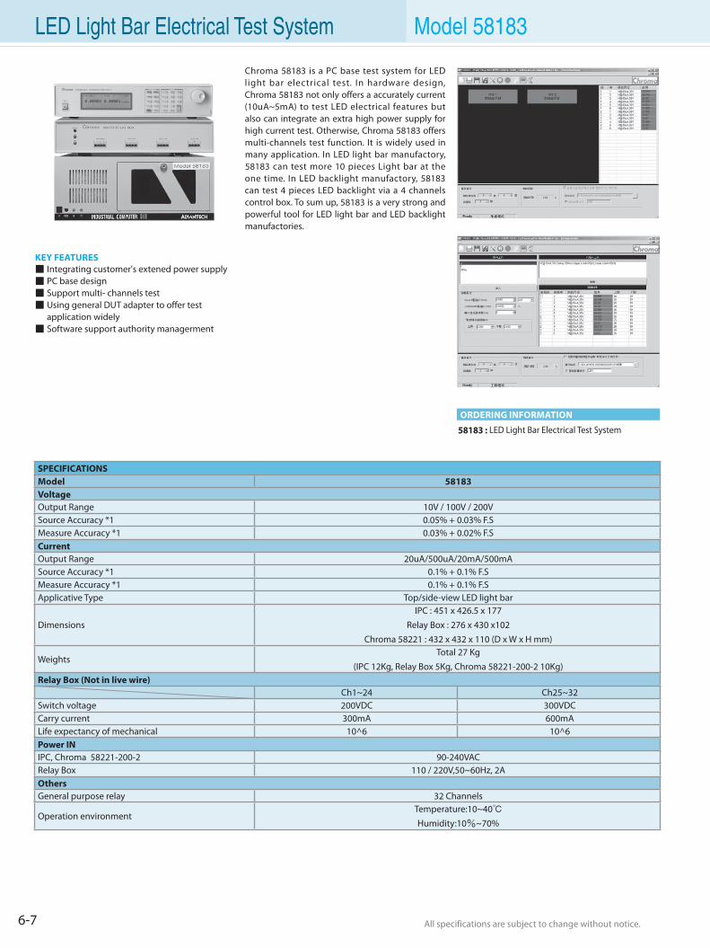
6-7 All specifications are subject to change without notice. All specifications are subject to change without notice.
LED Light Bar Electrical Test System Model 58183
KEY FEATURES Integrating customer's extened power supply PC base design Support multi- channels test Using general DUT adapter to offer test application widely Software support authority managerment
58183 : LED Light Bar Electrical Test System
ORDERING INFORMATION
Chroma 58183 is a PC base test system for LED light bar electrical test. In hardware design, Chroma 58183 not only offers a accurately current (10uA~5mA) to test LED electrical features but also can integrate an extra high power supply for high current test. Otherwise, Chroma 58183 offers multi-channels test function. It is widely used in many application. In LED light bar manufactory, 58183 can test more 10 pieces Light bar at the one time. In LED backlight manufactory, 58183 can test 4 pieces LED backlight via a 4 channels control box. To sum up, 58183 is a very strong and powerful tool for LED light bar and LED backlight manufactories.
SPECIFICATIONSModel 58183VoltageOutput Range 10V / 100V / 200VSource Accuracy *1 0.05% + 0.03% F.SMeasure Accuracy *1 0.03% + 0.02% F.SCurrentOutput Range 20uA/500uA/20mA/500mASource Accuracy *1 0.1% + 0.1% F.SMeasure Accuracy *1 0.1% + 0.1% F.SApplicative Type Top/side-view LED light bar
DimensionsIPC : 451 x 426.5 x 177
Relay Box : 276 x 430 x102Chroma 58221 : 432 x 432 x 110 (D x W x H mm)
WeightsTotal 27 Kg
(IPC 12Kg, Relay Box 5Kg, Chroma 58221-200-2 10Kg)Relay Box (Not in live wire)
Ch1~24 Ch25~32Switch voltage 200VDC 300VDCCarry current 300mA 600mALife expectancy of mechanical 10^6 10^6Power INIPC, Chroma 58221-200-2 90-240VACRelay Box 110 / 220V,50~60Hz, 2AOthersGeneral purpose relay 32 Channels
Operation environmentTemperature:10~40Humidity:10%~70%
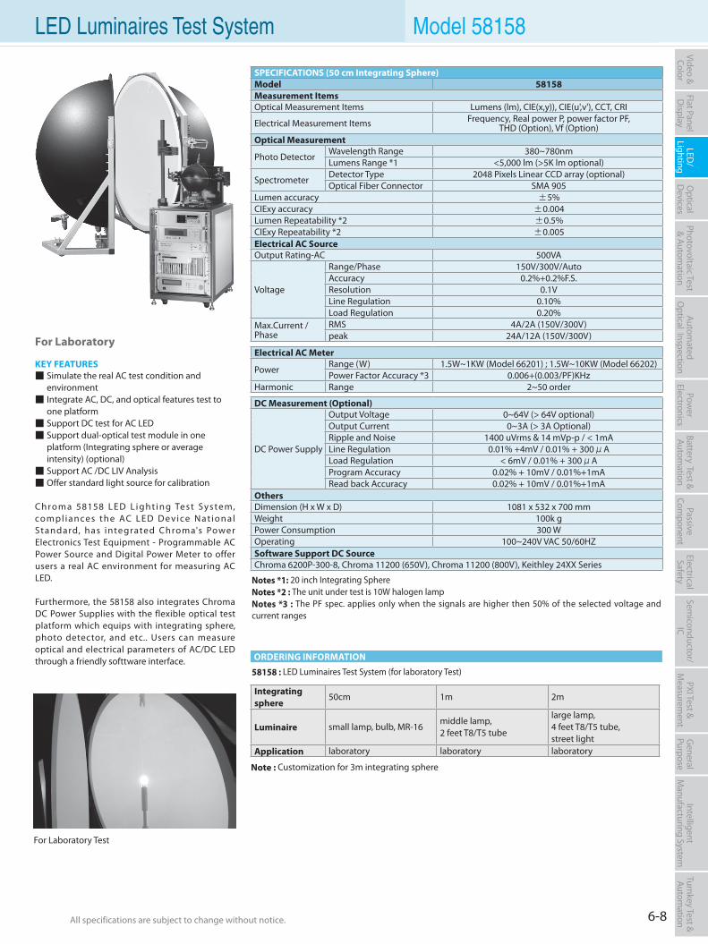
6-8All specifications are subject to change without notice. All specifications are subject to change without notice.
Flat PanelD
isplayPow
er Electronics
Electrical Safety
General
PurposePassive
Component
Semiconductor/
ICBattery Test & Autom
ationAutom
atedO
ptical Inspection Photovoltaic Test
& Automation
PXI Test &
Measurem
ent Video & Color
LED/
LightingO
ptical D
evicesIntelligent
Manufacturing System
Turnkey Test & Autom
ation LED Luminaires Test System Model 58158
For Laboratory
KEY FEATURES Simulate the real AC test condition and
environment Integrate AC, DC, and optical features test to
one platform Support DC test for AC LED Support dual-optical test module in one
platform (Integrating sphere or average intensity) (optional) Support AC /DC LIV Analysis Offer standard light source for calibration
C h ro m a 58158 L E D L i g ht i n g Te s t Sys te m, co m pl i a n ce s t h e AC L E D D e v i ce N at i o n a l Standard, has integrated Chroma's Power Electronics Test Equipment - Programmable AC Power Source and Digital Power Meter to offer users a real AC environment for measuring AC LED.
Furthermore, the 58158 also integrates Chroma DC Power Supplies with the flexible optical test platform which equips with integrating sphere, photo detector, and etc.. Users can measure optical and electrical parameters of AC/DC LED through a friendly softtware interface.
58158 : LED Luminaires Test System (for laboratory Test)
Notes *1: 20 inch Integrating SphereNotes *2 : The unit under test is 10W halogen lampNotes *3 : The PF spec. applies only when the signals are higher then 50% of the selected voltage and current ranges
ORDERING INFORMATION
SPECIFICATIONS (50 cm Integrating Sphere)Model 58158 Measurement ItemsOptical Measurement Items Lumens (lm), CIE(x,y)), CIE(u',v'), CCT, CRI
Electrical Measurement Items Frequency, Real power P, power factor PF, THD (Option), Vf (Option)
Optical Measurement
Photo DetectorWavelength Range 380~780nmLumens Range *1 <5,000 lm (>5K lm optional)
SpectrometerDetector Type 2048 Pixels Linear CCD array (optional)Optical Fiber Connector SMA 905
Lumen accuracy ±5%CIExy accuracy ±0.004Lumen Repeatability *2 ±0.5%CIExy Repeatability *2 ±0.005Electrical AC SourceOutput Rating-AC 500VA
Voltage
Range/Phase 150V/300V/AutoAccuracy 0.2%+0.2%F.S.Resolution 0.1VLine Regulation 0.10%Load Regulation 0.20%
Max.Current / Phase
RMS 4A/2A (150V/300V)peak 24A/12A (150V/300V)
DC Measurement (Optional)
DC Power Supply
Output Voltage 0~64V (> 64V optional)Output Current 0~3A (> 3A Optional)Ripple and Noise 1400 uVrms & 14 mVp-p / < 1mALine Regulation 0.01% +4mV / 0.01% + 300μALoad Regulation < 6mV / 0.01% + 300μAProgram Accuracy 0.02% + 10mV / 0.01%+1mARead back Accuracy 0.02% + 10mV / 0.01%+1mA
OthersDimension (H x W x D) 1081 x 532 x 700 mmWeight 100k gPower Consumption 300 WOperating 100~240V VAC 50/60HZSoftware Support DC SourceChroma 6200P-300-8, Chroma 11200 (650V), Chroma 11200 (800V), Keithley 24XX Series
Electrical AC Meter
PowerRange (W) 1.5W~1KW (Model 66201) ; 1.5W~10KW (Model 66202)Power Factor Accuracy *3 0.006+(0.003/PF)KHz
Harmonic Range 2~50 order
For Laboratory Test
Integrating sphere
50cm 1m 2m
Luminaire small lamp, bulb, MR-16middle lamp, 2 feet T8/T5 tube
large lamp, 4 feet T8/T5 tube, street light
Application laboratory laboratory laboratory
Note : Customization for 3m integrating sphere
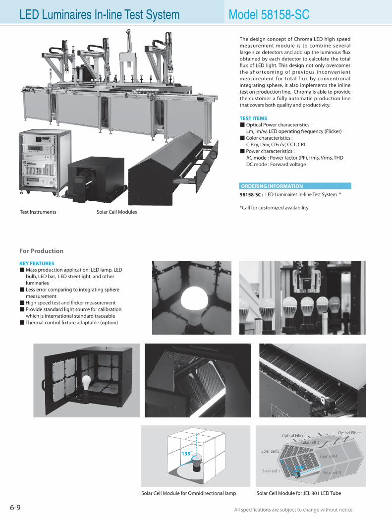
6-9 All specifications are subject to change without notice. All specifications are subject to change without notice.
58158-SC : LED Luminaires In-line Test System *
*Call for customized availability
ORDERING INFORMATION
LED Luminaires In-line Test System
The design concept of Chroma LED high speed measurement module is to combine several large size detectors and add up the luminous flux obtained by each detector to calculate the total flux of LED light. This design not only overcomes the shor tcoming of previous inconvenient measurement for total flux by conventional integrating sphere, it also implements the inline test on production line. Chroma is able to provide the customer a fully automatic production line that covers both quality and productivity.
TEST ITEMS Optical Power characteristics : Lm, lm/w, LED operating frequency (Flicker) Color characteristics : CIExy, Duv, CIEu'v', CCT, CRI Power characteristics : AC mode : Power factor (PF), Irms, Vrms, THD DC mode : Forward voltage
For Production
KEY FEATURES Mass production application: LED lamp, LED bulb, LED bar, LED streetlight, and other luminaries Less error comparing to integrating sphere measurement High speed test and flicker measurement Provide standard light source for calibration which is international standard traceable Thermal control fixture adaptable (option)
120°
135°
Test Instruments Solar Cell Modules
Model 58158-SC
Solar Cell Module for JEL 801 LED Tube Solar Cell Module for Omnidirectional lamp
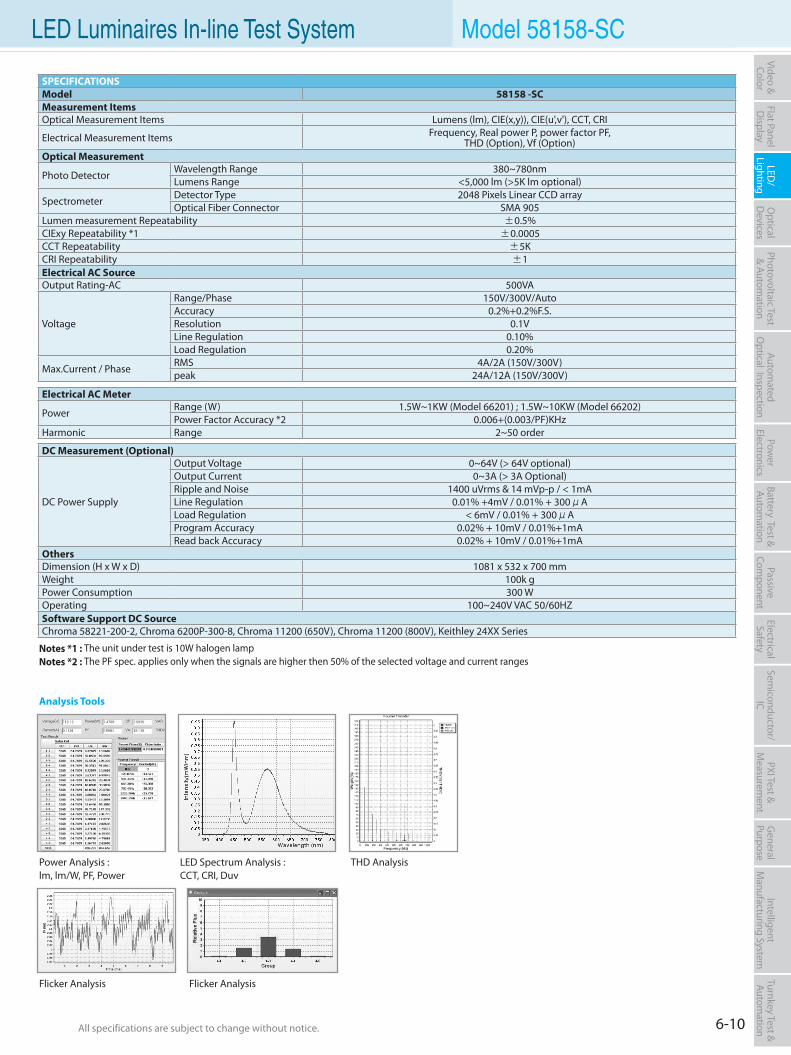
6-10All specifications are subject to change without notice. All specifications are subject to change without notice.
Flat PanelD
isplayPow
er Electronics
Electrical Safety
General
PurposePassive
Component
Semiconductor/
ICBattery Test & Autom
ationAutom
atedO
ptical Inspection Photovoltaic Test
& Automation
PXI Test &
Measurem
ent Video & Color
LED/
LightingO
ptical D
evicesIntelligent
Manufacturing System
Turnkey Test & Autom
ation LED Luminaires In-line Test System Model 58158-SC
Power Analysis :lm, lm/W, PF, Power
LED Spectrum Analysis :CCT, CRI, Duv
THD Analysis
Flicker Analysis Flicker Analysis
Analysis Tools
Notes *1 : The unit under test is 10W halogen lampNotes *2 : The PF spec. applies only when the signals are higher then 50% of the selected voltage and current ranges
SPECIFICATIONS Model 58158 -SCMeasurement ItemsOptical Measurement Items Lumens (lm), CIE(x,y)), CIE(u',v'), CCT, CRI
Electrical Measurement Items Frequency, Real power P, power factor PF, THD (Option), Vf (Option)
Optical Measurement
Photo DetectorWavelength Range 380~780nmLumens Range <5,000 lm (>5K lm optional)
SpectrometerDetector Type 2048 Pixels Linear CCD arrayOptical Fiber Connector SMA 905
Lumen measurement Repeatability ±0.5%CIExy Repeatability *1 ±0.0005CCT Repeatability ±5KCRI Repeatability ±1Electrical AC SourceOutput Rating-AC 500VA
Voltage
Range/Phase 150V/300V/AutoAccuracy 0.2%+0.2%F.S.Resolution 0.1VLine Regulation 0.10%Load Regulation 0.20%
Max.Current / PhaseRMS 4A/2A (150V/300V)peak 24A/12A (150V/300V)
DC Measurement (Optional)
DC Power Supply
Output Voltage 0~64V (> 64V optional)Output Current 0~3A (> 3A Optional)Ripple and Noise 1400 uVrms & 14 mVp-p / < 1mALine Regulation 0.01% +4mV / 0.01% + 300μALoad Regulation < 6mV / 0.01% + 300μAProgram Accuracy 0.02% + 10mV / 0.01%+1mARead back Accuracy 0.02% + 10mV / 0.01%+1mA
OthersDimension (H x W x D) 1081 x 532 x 700 mmWeight 100k gPower Consumption 300 WOperating 100~240V VAC 50/60HZSoftware Support DC SourceChroma 58221-200-2, Chroma 6200P-300-8, Chroma 11200 (650V), Chroma 11200 (800V), Keithley 24XX Series
Electrical AC Meter
PowerRange (W) 1.5W~1KW (Model 66201) ; 1.5W~10KW (Model 66202)Power Factor Accuracy *2 0.006+(0.003/PF)KHz
Harmonic Range 2~50 order

Optical Devices Test Solution
TO-CAN/CoC Burn In System 7-1
Laser Diode Characterization System 7-5
TOSA/BOSA Temperature Control System 7-7
TO-CAN Package Inspection System 7-9
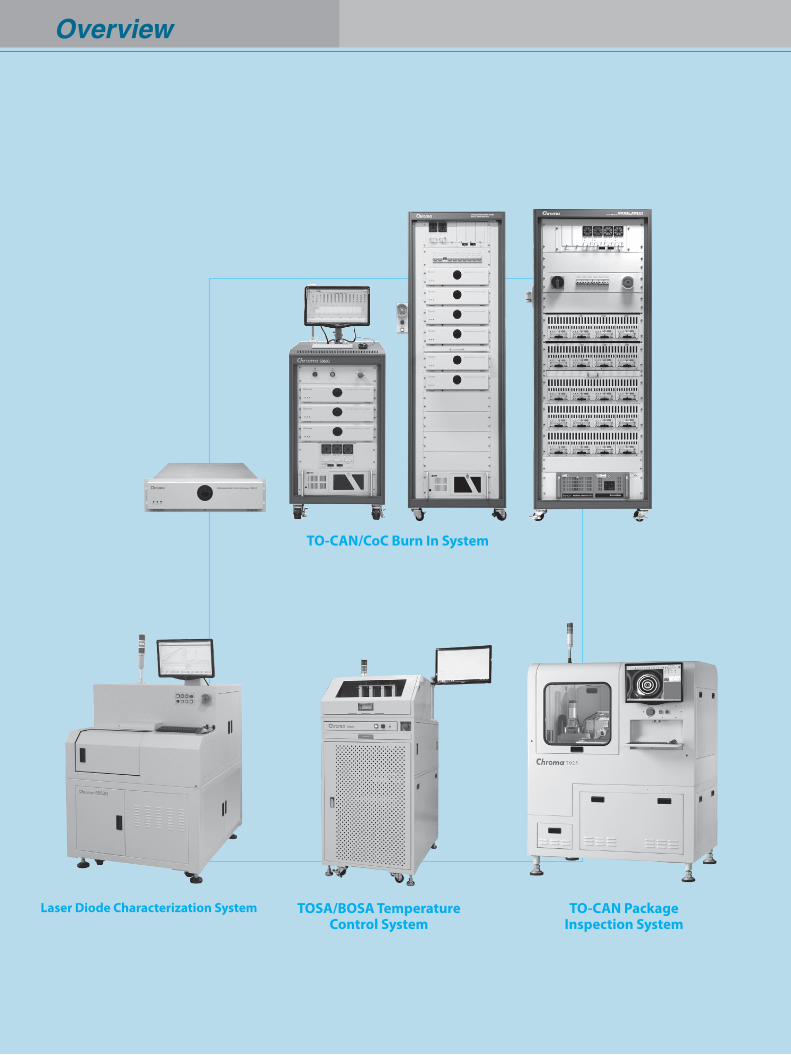
Overview
TOSA/BOSA TemperatureControl System
TO-CAN Package Inspection System
TO-CAN/CoC Burn In System
Laser Diode Characterization System
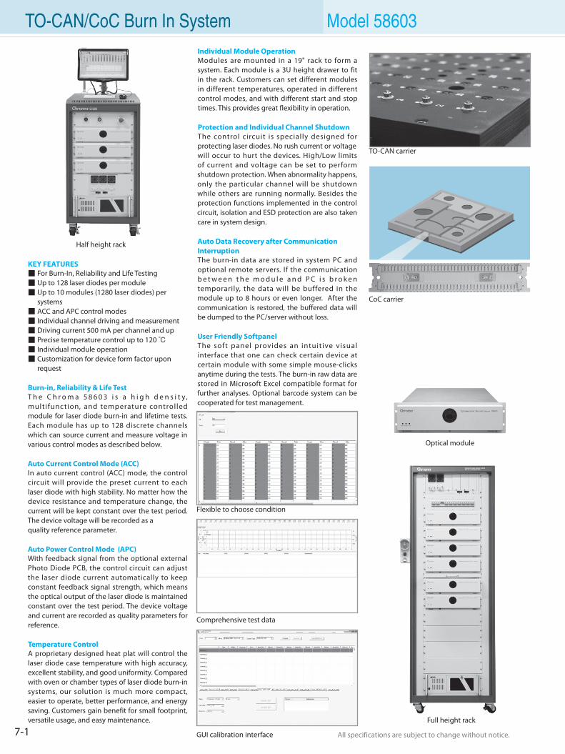
7-1 All specifications are subject to change without notice. All specifications are subject to change without notice.
Optical module
TO-CAN/CoC Burn In System Model 58603Individual Module OperationModules are mounted in a 19" rack to form a system. Each module is a 3U height drawer to fit in the rack. Customers can set different modules in different temperatures, operated in different control modes, and with different start and stop times. This provides great flexibility in operation.
Protection and Individual Channel ShutdownThe control circuit is specially designed for protecting laser diodes. No rush current or voltagewill occur to hurt the devices. High/Low limits of current and voltage can be set to perform shutdown protection. When abnormality happens, only the particular channel will be shutdown while others are running normally. Besides the protection functions implemented in the control circuit, isolation and ESD protection are also taken care in system design.
Auto Data Recovery after Communication InterruptionThe burn-in data are stored in system PC and optional remote servers. If the communication b e t w e e n t h e m o d u l e a n d P C i s b r o k e n temporarily, the data will be buffered in the module up to 8 hours or even longer. After the communication is restored, the buffered data will be dumped to the PC/server without loss.
User Friendly SoftpanelThe soft panel provides an intuitive visual interface that one can check certain device at certain module with some simple mouse-clicks anytime during the tests. The burn-in raw data are stored in Microsoft Excel compatible format for further analyses. Optional barcode system can be cooperated for test management.
KEY FEATURES For Burn-In, Reliability and Life Testing Up to 128 laser diodes per module Up to 10 modules (1280 laser diodes) per systems ACC and APC control modes Individual channel driving and measurement Driving current 500 mA per channel and up Precise temperature control up to 120 Individual module operation Customization for device form factor upon request
Burn-in, Reliability & Life TestT h e C h r o m a 5 8 6 0 3 i s a h i g h d e n s i t y , multifunction, and temperature controlled module for laser diode burn-in and lifetime tests. Each module has up to 128 discrete channels which can source current and measure voltage in various control modes as described below.
Auto Current Control Mode (ACC)In auto current control (ACC) mode, the control circuit will provide the preset current to each laser diode with high stability. No matter how the device resistance and temperature change, the current will be kept constant over the test period. The device voltage will be recorded as aquality reference parameter.
Auto Power Control Mode (APC)With feedback signal from the optional external Photo Diode PCB, the control circuit can adjust the laser diode current automatically to keep constant feedback signal strength, which means the optical output of the laser diode is maintained constant over the test period. The device voltage and current are recorded as quality parameters for reference.
Temperature ControlA proprietary designed heat plat will control the laser diode case temperature with high accuracy, excellent stability, and good uniformity. Compared with oven or chamber types of laser diode burn-in systems, our solution is much more compact, easier to operate, better performance, and energy saving. Customers gain benefit for small footprint, versatile usage, and easy maintenance.
Flexible to choose condition
TO-CAN carrier
Comprehensive test data
CoC carrier
GUI calibration interface
Half height rack
Full height rack
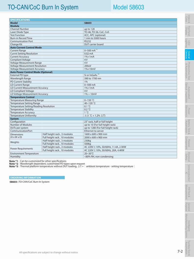
7-2All specifications are subject to change without notice. All specifications are subject to change without notice.
Flat PanelD
isplayPow
er Electronics
Electrical Safety
General
PurposePassive
Component
Semiconductor/
ICBattery Test & Autom
ationAutom
atedO
ptical Inspection Photovoltaic Test
& Automation
PXI Test &
Measurem
ent Video & Color
LED/
LightingO
ptical D
evicesIntelligent
Manufacturing System
Turnkey Test & Autom
ation TO-CAN/CoC Burn In System Model 58603
ORDERING INFORMATION
58603 : TO-CAN/CoC Burn In System
SPECIFICATIONSModel 58603ModuleChannel Number up to 128Laser Diode Type TO-46, TO-56, CoC, CoSTest Function ACC, APC (optional)Burn-in Record Time 1 min to 5000 hoursCommunication Port RS232Change Kit DUT carrier boardAuto Current Control ModeCurrent Range 0~500 mA *1
Currnt Setting Resolution 0.02 mACurrent Accuracy 1%+1mACompliant Voltage 4 VVoltage Measurement Range 4 VVoltage Measurement Resolution 200uVVoltage Measurement Accuracy 1%+10mVAuto Power Control Mode (Optional)External PD type Si or InGaAs *2
Wavelength Range 390 to 1700 nmPD Current Stability 1%LD Current Range 0~500 mALD Current Measurement Accuracy 1%+1mALD Compliant Voltage 4 VLD Voltage Measurement Accuracy 1% + 10mVTemperature ControlTemperature Measuring Range 0~150 Temperature Setting Range 40~120 Temperature Setting/Reading Resolution 0.1 Temperature Stability 0.2 Temperature Accuracy 1 Temperature Uniformity ±(1 + 1.2% ΔT)SystemConfiguration 23" rack, half or full heightNumber of Modules up to 10 (For full height rack)DUTs per system up to 1280 (For full height rack)CommunicationPort Ethernet to serverDimensions(H x W x D)
Half height rack , 3 modules 1600 x 600 x 900 mmFull height rack , 10 modules 2000 x 600 x 900 mm
Weights Half height rack , 3 modules 230kgFull height rack , 10 modules 500kg
Power RequirementsHalf height rack , 3 modules AC 220V±10%, 50/60Hz, 11.4A, 2.5KW Full height rack , 10 modules AC 220V±10%, 50/60Hz, 20A, 4.4KW
Environment Temperature 20~30Humidity <80% RH, non-condensing
Note *1 : Can be customized for other specificationsNote *2 : Wavelength dependent, customized PD types upon requestNote *3 : Thermal platform temperature without DUT loading, ΔT =ambient temperature - setting temperature
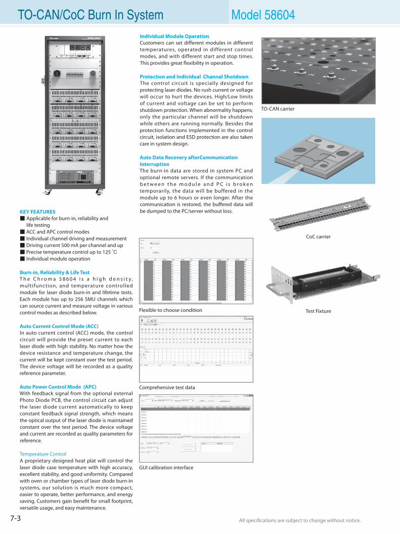
7-3 All specifications are subject to change without notice. All specifications are subject to change without notice.
TO-CAN/CoC Burn In System Model 58604Individual Module OperationCustomers can set different modules in different temperatures, operated in different control modes, and with different start and stop times. This provides great flexibility in operation.
Protection and Individual Channel ShotdownThe control circuit is specially designed for protecting laser diodes. No rush current or voltage will occur to hurt the devices. High/Low limits of current and voltage can be set to perform shutdown protection. When abnormality happens, only the particular channel will be shutdown while others are running normally. Besides the protection functions implemented in the control circuit, isolation and ESD protection are also taken care in system design.
Auto Data Recovery afterCommunication InterruptionThe burn-in data are stored in system PC and optional remote servers. If the communication b e t w e e n t h e m o d u l e a n d P C i s b r o k e n temporarily, the data will be buffered in the module up to 6 hours or even longer. After the communication is restored, the buffered data will be dumped to the PC/server without loss.KEY FEATURES
Applicable for burn-in, reliability and life testing ACC and APC control modes Individual channel driving and measurement Driving current 500 mA per channel and up Precise temperature control up to 125 Individual module operation
Burn-in, Reliability & Life TestT h e C h r o m a 5 8 6 0 4 i s a h i g h d e n s i t y , multifunction, and temperature controlled module for laser diode burn-in and lifetime tests. Each module has up to 256 SMU channels which can source current and measure voltage in various control modes as described below.
Auto Current Control Mode (ACC)In auto current control (ACC) mode, the control circuit will provide the preset current to each laser diode with high stability. No matter how the device resistance and temperature change, the current will be kept constant over the test period. The device voltage will be recorded as a quality reference parameter.
Auto Power Control Mode (APC)With feedback signal from the optional external Photo Diode PCB, the control circuit can adjust the laser diode current automatically to keep constant feedback signal strength, which means the optical output of the laser diode is maintained constant over the test period. The device voltage and current are recorded as quality parameters for reference.
Temperature ControlA proprietary designed heat plat will control the laser diode case temperature with high accuracy, excellent stability, and good uniformity. Compared with oven or chamber types of laser diode burn-in systems, our solution is much more compact, easier to operate, better performance, and energy saving. Customers gain benefit for small footprint, versatile usage, and easy maintenance.
Flexible to choose condition
TO-CAN carrier
Comprehensive test data
CoC carrier
Test Fixture
GUI calibration interface
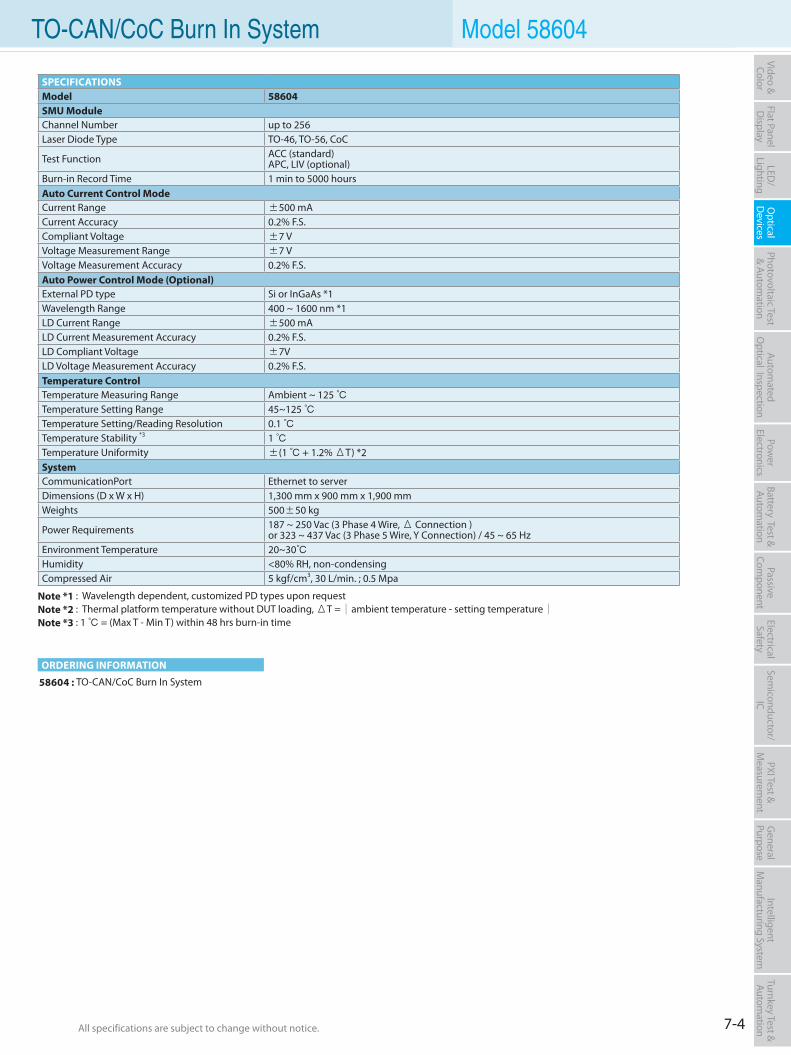
7-4All specifications are subject to change without notice. All specifications are subject to change without notice.
Flat PanelD
isplayPow
er Electronics
Electrical Safety
General
PurposePassive
Component
Semiconductor/
ICBattery Test & Autom
ationAutom
atedO
ptical Inspection Photovoltaic Test
& Automation
PXI Test &
Measurem
ent Video & Color
LED/
LightingO
ptical D
evicesIntelligent
Manufacturing System
Turnkey Test & Autom
ation TO-CAN/CoC Burn In System Model 58604
ORDERING INFORMATION
58604 : TO-CAN/CoC Burn In System
SPECIFICATIONSModel 58604SMU ModuleChannel Number up to 256Laser Diode Type TO-46, TO-56, CoC
Test Function ACC (standard)APC, LIV (optional)
Burn-in Record Time 1 min to 5000 hoursAuto Current Control ModeCurrent Range ±500 mACurrent Accuracy 0.2% F.S.Compliant Voltage ±7 VVoltage Measurement Range ±7 VVoltage Measurement Accuracy 0.2% F.S.Auto Power Control Mode (Optional)External PD type Si or InGaAs *1Wavelength Range 400 ~ 1600 nm *1LD Current Range ±500 mALD Current Measurement Accuracy 0.2% F.S.LD Compliant Voltage ±7VLD Voltage Measurement Accuracy 0.2% F.S.Temperature ControlTemperature Measuring Range Ambient ~ 125 Temperature Setting Range 45~125 Temperature Setting/Reading Resolution 0.1 Temperature Stability *3 1 Temperature Uniformity ±(1 + 1.2% ΔT) *2SystemCommunicationPort Ethernet to serverDimensions (D x W x H) 1,300 mm x 900 mm x 1,900 mmWeights 500±50 kg
Power Requirements 187 ~ 250 Vac (3 Phase 4 Wire, Δ Connection ) or 323 ~ 437 Vac (3 Phase 5 Wire, Y Connection) / 45 ~ 65 Hz
Environment Temperature 20~30Humidity <80% RH, non-condensingCompressed Air 5 kgf/cm3, 30 L/min. ; 0.5 Mpa
Note *1 : Wavelength dependent, customized PD types upon requestNote *2 : Thermal platform temperature without DUT loading, ΔT =ambient temperature - setting temperatureNote *3 : 1 = (Max T - Min T) within 48 hrs burn-in time
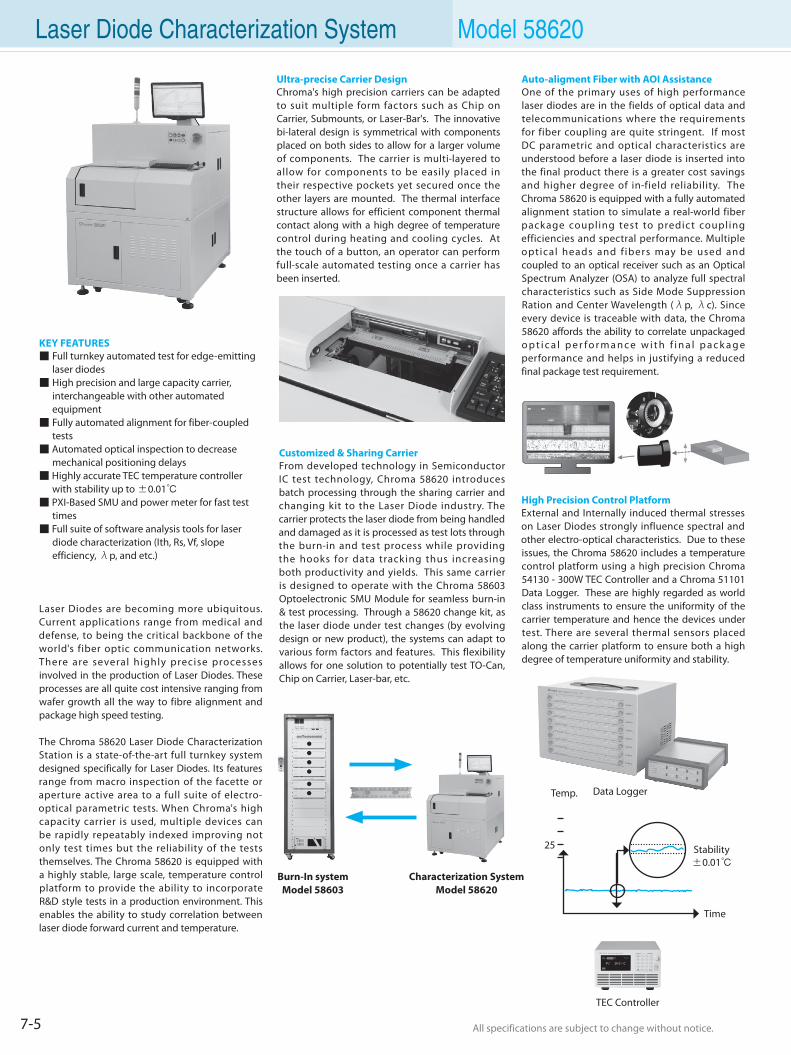
7-5 All specifications are subject to change without notice. All specifications are subject to change without notice.
TEC Controller
Data Logger
Characterization System Model 58620
Burn-In systemModel 58603
Laser Diode Characterization System Model 58620
KEY FEATURES Full turnkey automated test for edge-emitting laser diodes High precision and large capacity carrier, interchangeable with other automated equipment Fully automated alignment for fiber-coupled tests Automated optical inspection to decrease mechanical positioning delays Highly accurate TEC temperature controller with stability up to ±0.01 PXI-Based SMU and power meter for fast test times Full suite of software analysis tools for laser diode characterization (Ith, Rs, Vf, slope efficiency, λp, and etc.)
Laser Diodes are becoming more ubiquitous. Current applications range from medical and defense, to being the critical backbone of the world's fiber optic communication networks. There are several highly precise processes involved in the production of Laser Diodes. These processes are all quite cost intensive ranging from wafer growth all the way to fibre alignment and package high speed testing.
The Chroma 58620 Laser Diode Characterization Station is a state-of-the-art full turnkey system designed specifically for Laser Diodes. Its features range from macro inspection of the facette or aperture active area to a full suite of electro-optical parametric tests. When Chroma's high capacity carrier is used, multiple devices can be rapidly repeatably indexed improving not only test times but the reliability of the tests themselves. The Chroma 58620 is equipped with a highly stable, large scale, temperature control platform to provide the ability to incorporate R&D style tests in a production environment. This enables the ability to study correlation between laser diode forward current and temperature.
Ultra-precise Carrier DesignChroma's high precision carriers can be adapted to suit multiple form factors such as Chip on Carrier, Submounts, or Laser-Bar's. The innovative bi-lateral design is symmetrical with components placed on both sides to allow for a larger volume of components. The carrier is multi-layered to allow for components to be easily placed in their respective pockets yet secured once the other layers are mounted. The thermal interface structure allows for efficient component thermal contact along with a high degree of temperature control during heating and cooling cycles. At the touch of a button, an operator can perform full-scale automated testing once a carrier has been inserted.
Auto-aligment Fiber with AOI AssistanceOne of the primary uses of high performance laser diodes are in the fields of optical data and telecommunications where the requirements for fiber coupling are quite stringent. If most DC parametric and optical characteristics are understood before a laser diode is inserted into the final product there is a greater cost savings and higher degree of in-field reliability. The Chroma 58620 is equipped with a fully automated alignment station to simulate a real-world fiber package coupling test to predict coupling efficiencies and spectral performance. Multiple optical heads and f ibers may be used and coupled to an optical receiver such as an Optical Spectrum Analyzer (OSA) to analyze full spectral characteristics such as Side Mode Suppression Ration and Center Wavelength (λp, λc). Since every device is traceable with data, the Chroma 58620 affords the ability to correlate unpackaged o p t i c a l p e r f o r m a n c e w i t h f i n a l p a c k a g e performance and helps in justifying a reduced final package test requirement.
High Precision Control PlatformExternal and Internally induced thermal stresses on Laser Diodes strongly influence spectral and other electro-optical characteristics. Due to these issues, the Chroma 58620 includes a temperature control platform using a high precision Chroma 54130 - 300W TEC Controller and a Chroma 51101 Data Logger. These are highly regarded as world class instruments to ensure the uniformity of the carrier temperature and hence the devices under test. There are several thermal sensors placed along the carrier platform to ensure both a high degree of temperature uniformity and stability.
Customized & Sharing CarrierFrom developed technology in Semiconductor IC test technology, Chroma 58620 introduces batch processing through the sharing carrier and changing kit to the Laser Diode industry. The carrier protects the laser diode from being handled and damaged as it is processed as test lots through the burn-in and test process while providing the hooks for data tracking thus increasing both productivity and yields. This same carrier is designed to operate with the Chroma 58603 Optoelectronic SMU Module for seamless burn-in & test processing. Through a 58620 change kit, as the laser diode under test changes (by evolving design or new product), the systems can adapt to various form factors and features. This flexibility allows for one solution to potentially test TO-Can, Chip on Carrier, Laser-bar, etc.
Time
Temp.
25 Stability±0.01
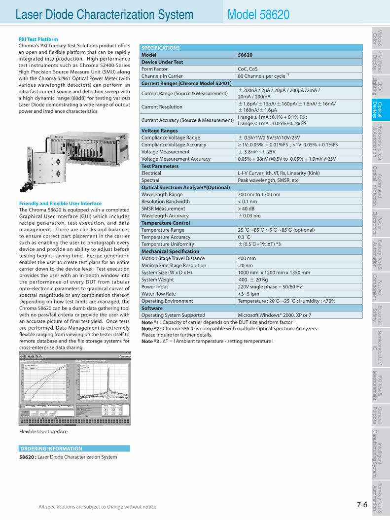
7-6All specifications are subject to change without notice. All specifications are subject to change without notice.
Flat PanelD
isplayPow
er Electronics
Electrical Safety
General
PurposePassive
Component
Semiconductor/
ICBattery Test & Autom
ationAutom
atedO
ptical Inspection Photovoltaic Test
& Automation
PXI Test &
Measurem
ent Video & Color
LED/
LightingO
ptical D
evicesIntelligent
Manufacturing System
Turnkey Test & Autom
ation Laser Diode Characterization System Model 58620
ORDERING INFORMATION
58620 : Laser Diode Characterization System
Flexible User Interface
Friendly and Flexible User InterfaceThe Chroma 58620 is equipped with a completed Graphical User Interface (GUI) which includes recipe generation, test execution, and data management. There are checks and balances to ensure correct part placement in the carrier such as enabling the user to photograph every device and provide an ability to adjust before testing begins, saving time. Recipe generation enables the user to create test plans for an entire carrier down to the device level. Test execution provides the user with an in-depth window into the performance of every DUT from tabular opto-electronic parameters to graphical curves of spectral magnitude or any combination thereof. Depending on how test limits are managed, the Chroma 58620 can be a dumb data gathering tool with no pass/fail criteria or provide the user with an accurate picture of final test yield. Once tests are performed, Data Management is extremely flexible ranging from viewing on the tester itself to remote database and the file storage systems for cross-enterprise data sharing.
PXI Test PlatformChroma's PXI Turnkey Test Solutions product offers an open and flexible platform that can be rapidly integrated into production. High performance test instruments such as Chroma 52400-Series High Precision Source Measure Unit (SMU) along with the Chroma 52961 Optical Power Meter (with various wavelength detectors) can perform an ultra-fast current source and detection sweep with a high dynamic range (80dB) for testing various Laser Diode demonstrating a wide range of output power and irradiance characteristics.
SPECIFICATIONSModel 58620Device Under TestForm Factor CoC, CoSChannels in Carrier 80 Channels per cycle *1
Current Ranges (Chroma Model 52401)
Current Range (Source & Measurement) ±200nA / 2µA / 20µA / 200µA /2mA / 20mA / 200mA
Current Resolution ±1.6pA/±16pA/±160pA/±1.6nA/±16nA/±160nA/±1.6µA
Current Accuracy (Source & Measurement) I range ≥ 1mA : 0.1% + 0.1% FS ;I range < 1mA : 0.05%+0.2% FS
Voltage RangesCompliance Voltage Range ± 0.5V/1V/2.5V/5V/10V/25VCompliance Voltage Accuracy ≥ 1V: 0.05% + 0.01%FS ; <1V: 0.05% + 0.1%FSVoltage Measurement ± 3.8nV~ ± 25VVoltage Measurement Accuracy 0.05% + 38nV @0.5V to 0.05% + 1.9mV @25VTest ParametersElectrical L-I-V Curves, Ith, Vf, Rs, Linearity (Kink)Spectral Peak wavelength, SMSR, etc.Optical Spectrum Analyzer*(Optional)Wavelength Range 700 nm to 1700 nmResolution Bandwidth < 0.1 nmSMSR Measurement > 40 dBWavelength Accuracy ±0.03 nmTemperature ControlTemperature Range 25 ~85 ; -5 ~85 (optional)Temperature Accuracy 0.3 Temperature Uniformity ±(0.5+1% ∆T) *3Mechanical SpecificationMotion Stage Travel Distance 400 mmMinima Fine Stage Resolution 20 nmSystem Size (W x D x H) 1000 mm x 1200 mm x 1350 mmSystem Weight 400 ± 20 KgPower Input 220V single phase,50/60 HzWater flow Rate <3~5 lpmOperating Environment Temperature : 20 ~25 ; Humidity : <70%SoftwareOperating System Supported Microsoft Windows® 2000, XP or 7Note *1 : Capacity of carrier depends on the DUT size and form factorNote *2 : Chroma 58620 is compatible with multiple Optical Spectrum Analyzers. Please inquire for further details.Note *3 : ∆T = l Ambient temperature - setting temperature l
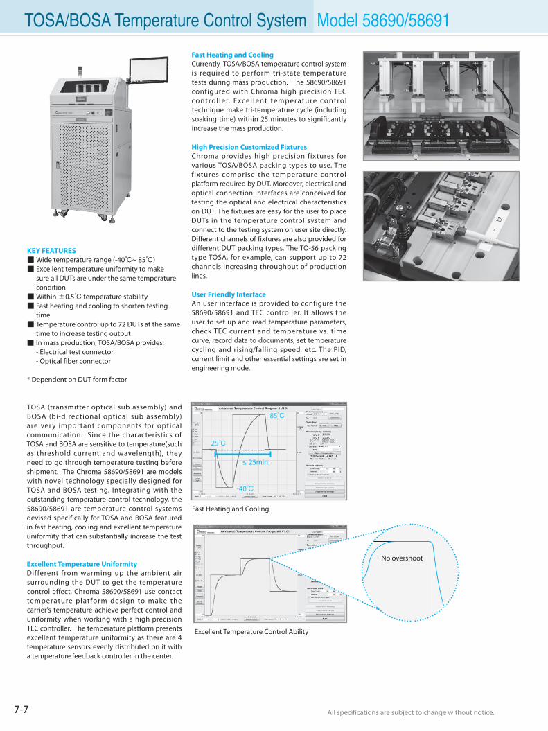
7-7 All specifications are subject to change without notice. All specifications are subject to change without notice.
TOSA/BOSA Temperature Control System Model 58690/58691
KEY FEATURES Wide temperature range (-40~ 85) Excellent temperature uniformity to make sure all DUTs are under the same temperature condition Within ±0.5 temperature stability Fast heating and cooling to shorten testing time Temperature control up to 72 DUTs at the same time to increase testing output In mass production, TOSA/BOSA provides: - Electrical test connector - Optical fiber connector
* Dependent on DUT form factor
TOSA (transmitter optical sub assembly) and BOSA (bi-directional optical sub assembly) are very important components for optical communication. Since the characteristics of TOSA and BOSA are sensitive to temperature(such as threshold current and wavelength), they need to go through temperature testing before shipment. The Chroma 58690/58691 are models with novel technology specially designed for TOSA and BOSA testing. Integrating with the outstanding temperature control technology, the 58690/58691 are temperature control systems devised specifically for TOSA and BOSA featured in fast heating, cooling and excellent temperature uniformity that can substantially increase the test throughput.
Excellent Temperature UniformityDifferent from warming up the ambient air surrounding the DUT to get the temperature control effect, Chroma 58690/58691 use contact temperature platform design to make the carrier's temperature achieve perfect control and uniformity when working with a high precision TEC controller. The temperature platform presents excellent temperature uniformity as there are 4 temperature sensors evenly distributed on it with a temperature feedback controller in the center.
Fast Heating and CoolingCurrently TOSA/BOSA temperature control system is required to perform tri-state temperature tests during mass production. The 58690/58691 configured with Chroma high precision TEC control ler. Excel lent temperature control technique make tri-temperature cycle (including soaking time) within 25 minutes to significantly increase the mass production.
High Precision Customized FixturesChroma provides high precision fixtures for various TOSA/BOSA packing types to use. The f ixtures comprise the temperature control platform required by DUT. Moreover, electrical and optical connection interfaces are conceived for testing the optical and electrical characteristics on DUT. The fixtures are easy for the user to place DUTs in the temperature control system and connect to the testing system on user site directly. Different channels of fixtures are also provided for different DUT packing types. The TO-56 packing type TOSA, for example, can support up to 72 channels increasing throughput of production lines.
User Friendly InterfaceAn user interface is provided to configure the 58690/58691 and TEC controller. It allows the user to set up and read temperature parameters, check TEC current and temperature vs. time curve, record data to documents, set temperature cycling and rising/falling speed, etc. The PID, current limit and other essential settings are set in engineering mode.
Fast Heating and Cooling
Excellent Temperature Control Ability
25
-40
≤ 25min.
85
No overshoot
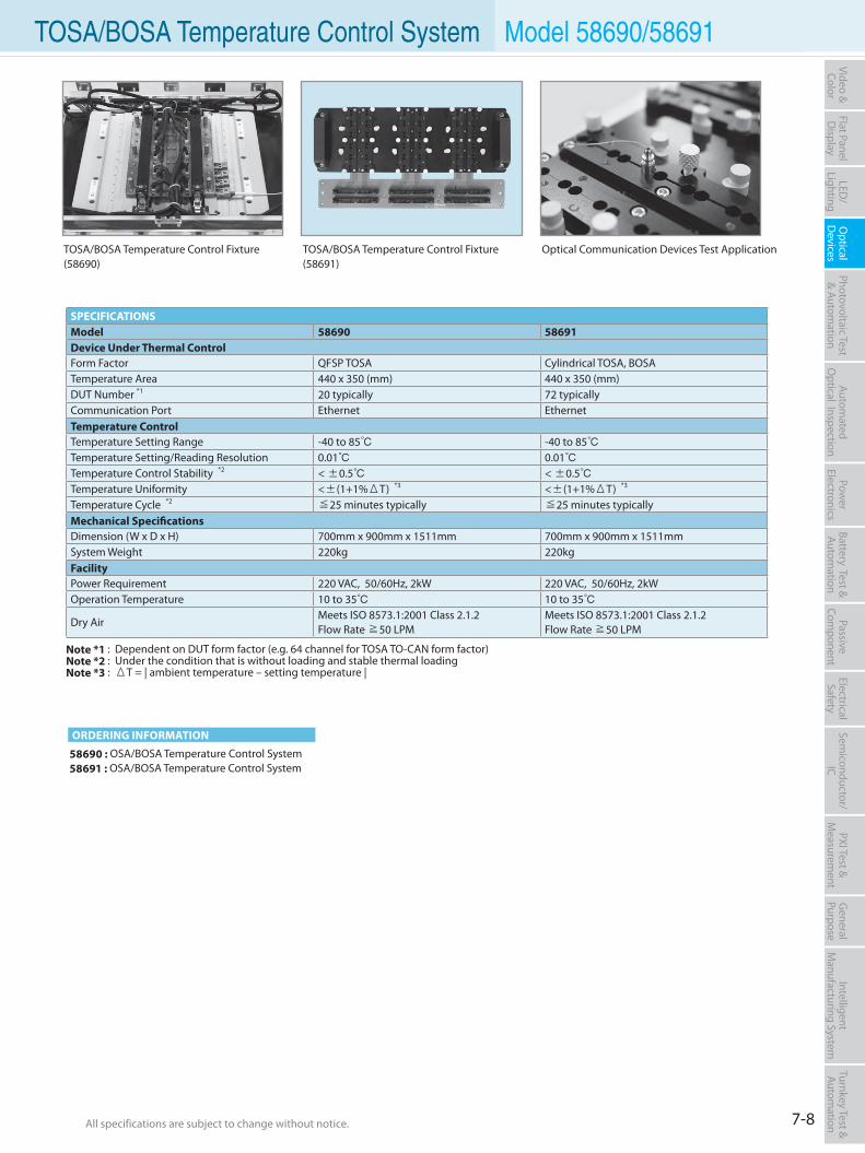
7-8All specifications are subject to change without notice. All specifications are subject to change without notice.
Flat PanelD
isplayPow
er Electronics
Electrical Safety
General
PurposePassive
Component
Semiconductor/
ICBattery Test & Autom
ationAutom
atedO
ptical Inspection Photovoltaic Test
& Automation
PXI Test &
Measurem
ent Video & Color
LED/
LightingO
ptical D
evicesIntelligent
Manufacturing System
Turnkey Test & Autom
ation TOSA/BOSA Temperature Control System Model 58690/58691
SPECIFICATIONSModel 58690 58691Device Under Thermal ControlForm Factor QFSP TOSA Cylindrical TOSA, BOSATemperature Area 440 x 350 (mm) 440 x 350 (mm)DUT Number *1 20 typically 72 typicallyCommunication Port Ethernet EthernetTemperature ControlTemperature Setting Range -40 to 85 -40 to 85Temperature Setting/Reading Resolution 0.01 0.01Temperature Control Stability *2 < ±0.5 < ±0.5Temperature Uniformity <±(1+1%ΔT) *3 <±(1+1%ΔT) *3
Temperature Cycle *2 ≦25 minutes typically ≦25 minutes typicallyMechanical SpecificationsDimension (W x D x H) 700mm x 900mm x 1511mm 700mm x 900mm x 1511mmSystem Weight 220kg 220kgFacilityPower Requirement 220 VAC, 50/60Hz, 2kW 220 VAC, 50/60Hz, 2kWOperation Temperature 10 to 35 10 to 35
Dry AirMeets ISO 8573.1:2001 Class 2.1.2Flow Rate ≧50 LPM
Meets ISO 8573.1:2001 Class 2.1.2Flow Rate ≧50 LPM
Note *1 : Dependent on DUT form factor (e.g. 64 channel for TOSA TO-CAN form factor)Note *2 : Under the condition that is without loading and stable thermal loadingNote *3 : ΔT = | ambient temperature – setting temperature |
TOSA/BOSA Temperature Control Fixture (58690)
TOSA/BOSA Temperature Control Fixture (58691)
Optical Communication Devices Test Application
ORDERING INFORMATION
58690 : OSA/BOSA Temperature Control System58691 : OSA/BOSA Temperature Control System
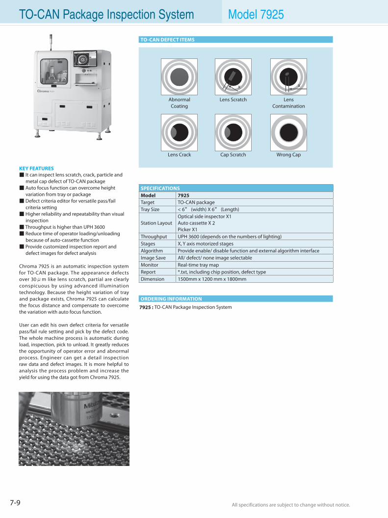
7-9 All specifications are subject to change without notice. All specifications are subject to change without notice.
ORDERING INFORMATION
TO-CAN DEFECT ITEMS
7925 : TO-CAN Package Inspection System
KEY FEATURES It can inspect lens scratch, crack, particle and metal cap defect of TO-CAN package Auto focus function can overcome height variation from tray or package Defect criteria editor for versatile pass/fail criteria setting Higher reliability and repeatability than visual inspection Throughput is higher than UPH 3600 Reduce time of operator loading/unloading because of auto-cassette function Provide customized inspection report and defect images for defect analysis
Chroma 7925 is an automatic inspection system for TO-CAN package. The appearance defects over 30μm like lens scratch, partial are clearly conspicuous by using advanced illumination technology. Because the height variation of tray and package exists, Chroma 7925 can calculate the focus distance and compensate to overcome the variation with auto focus function.
User can edit his own defect criteria for versatile pass/fail rule setting and pick by the defect code. The whole machine process is automatic during load, inspection, pick to unload. It greatly reduces the opportunity of operator error and abnormal process. Engineer can get a detail inspection raw data and defect images. It is more helpful to analysis the process problem and increase the yield for using the data got from Chroma 7925.
Abnormal Coating
Lens Scratch Lens Contamination
Lens Crack Cap Scratch Wrong Cap
SPECIFICATIONSModel 7925Target TO-CAN packageTray Size < 6” (width) X 6” (Length)
Station LayoutOptical side inspector X1Auto cassette X 2Picker X1
Throughput UPH 3600 (depends on the numbers of lighting)Stages X, Y axis motorized stagesAlgorithm Provide enable/ disable function and external algorithm interfaceImage Save All/ defect/ none image selectableMonitor Real-time tray mapReport *.txt, including chip position, defect typeDimension 1500mm x 1200 mm x 1800mm
TO-CAN Package Inspection System Model 7925
7-10All specifications are subject to change without notice. All specifications are subject to change without notice.
Flat PanelD
isplayPow
er Electronics
Electrical Safety
General
PurposePassive
Component
Semiconductor/
ICBattery Test & Autom
ationAutom
atedO
ptical Inspection Photovoltaic Test
& Automation
PXI Test &
Measurem
ent Video & Color
LED/
LightingO
ptical D
evicesIntelligent
Manufacturing System
Turnkey Test & Autom
ation TO-CAN Package Inspection System Model 7925
Solar Wafer Inspection System 8-1
Solar Cell Inspection Test/Sorting System 8-2
Solar Wafer Automatic Unloader 8-5
Solar Wafer/Cell Diffusion Loader/Unloader 8-6
Automatic Optical Solar Wafer/Cell Inspection System 8-7
c-Si Solar Cell Tester 8-11
Photovoltaic Test & Automation Solution
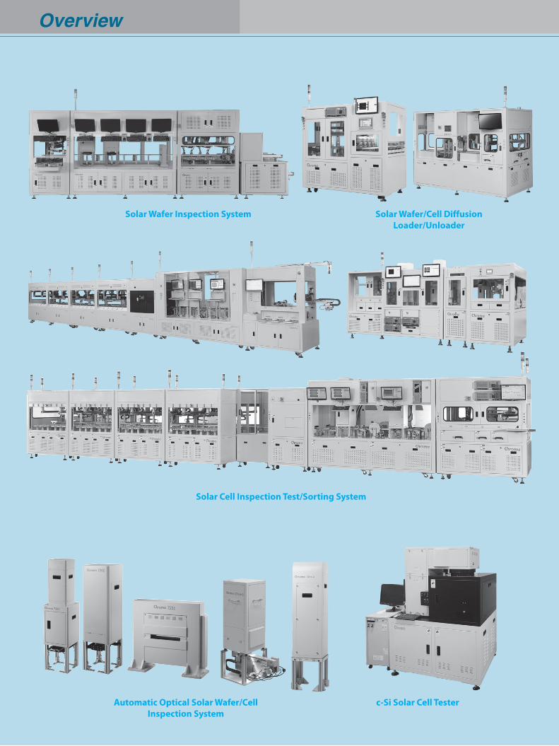
Overview
Solar Cell Inspection Test/Sorting System
Solar Wafer/Cell DiffusionLoader/Unloader
Automatic Optical Solar Wafer/Cell Inspection System
c-Si Solar Cell Tester
Solar Wafer Inspection System
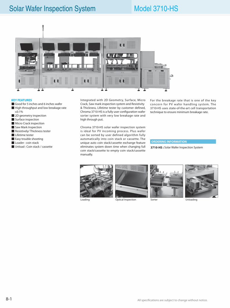
All specifications are subject to change without notice. All specifications are subject to change without notice.8-1
Solar Wafer Inspection System Model 3710-HS
KEY FEATURES Good for 5 inches and 6 inches wafer High throughput and low breakage rate ≤0.1% 2D geometry inspection Surface inspection Micro Crack inspection Saw Mark Inspection Resistively/ Thickness tester Lifetime tester Easy trouble shooting Loader : coin stack Unload : Coin stack / cassette 3710-HS : Solar Wafer Inspection System
Integrated with 2D Geometry, Surface, Micro Crack, Saw mark inspection system and Resistivity& Thickness, Lifetime tester by customer defined, Chroma 3710-HS is a fully user configuration wafersorter system with very low breakage rate and high through put.
Chroma 3710-HS solar wafer inspection system is ideal for PV incoming process. Plus wafer can be sorted by user defined algorithm fully automatically into coin stack or cassette. The unique auto coin stack/cassette exchange feature eliminates system down time when changing full coin stack/cassette to empty coin stack/cassette manually.
Loading SorterOptical Inspection Unloading
ORDERING INFORMATION
For the breakage rate that is one of the key concern for PV wafer handling system. The 3710-HS uses state-of-the-art cell transportation technique to ensure minimum breakage rate.
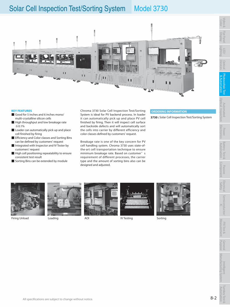
All specifications are subject to change without notice. All specifications are subject to change without notice. 8-2
Flat PanelD
isplayPow
er Electronics
Electrical Safety
General
PurposePassive
Component
Semiconductor/
ICBattery Test & Autom
ationAutom
atedO
ptical Inspection Photovoltaic Test
& Automation
PXI Test &
Measurem
ent Video & Color
LED/
LightingO
ptical D
evicesIntelligent
Manufacturing System
Turnkey Test & Autom
ation
KEY FEATURES Good for 5 inches and 6 inches mono/ multi-crystalline silicon cells High throughput and low breakage rate ≦0.1% Loader can automatically pick up and place cell finished by firing Efficiency and Color classes and Sorting Bins can be defined by customers' request Integrated with Inspector and IV Tester by customers' request High cell positioning repeatability to ensure consistent test result Sorting Bins can be extended by module
3730 : Solar Cell Inspection Test/Sorting System
Chroma 3730 Solar Cell Inspection Test/Sorting System is ideal for PV backend process. In loader it can automatically pick up and place PV cell finished by firing. Then it will inspect cell surface and backside defects and will automatically sort the cells into carrier by different efficiency and color classes defined by customers' request.
Breakage rate is one of the key concern for PV cell handling system. Chroma 3730 uses state-of-the-art cell transportation technique to ensure minimum breakage rate. Based on customer’s requirement of different processes, the carrier type and the amount of sorting bins also can be designed and adjusted.
ORDERING INFORMATION
Firing Unload Loading IV Testing SortingAOI
Solar Cell Inspection Test/Sorting System Model 3730
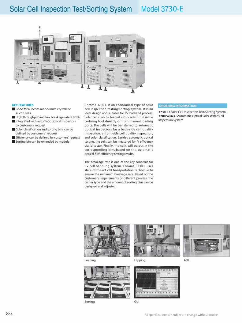
All specifications are subject to change without notice. All specifications are subject to change without notice.8-3
Solar Cell Inspection Test/Sorting System Model 3730-E
KEY FEATURES Good for 6 inches mono/multi crystalline
silicon cells High throughput and low breakage rate ≤ 0.1% Integrated with automatic optical inspectors by customers' request Color classification and sorting bins can be
defined by customers' request Efficiency can be defined by customers' request Sorting bin can be extended by module
3730-E : Solar Cell Inspection Test/Sorting System7200 Series : Automatic Optical Solar Wafer/CellInspection System
Chroma 3730-E is an economical type of solar cell inspection testing/sorting system. It is an ideal design and suitable for PV backend process. Solar cells can be loaded into loader from inline co-firing tool directly or from manual loading ports. The cells will be transferred to automatic optical inspectors for a back-side cell quality inspection, a front-side cell quality inspection, and color classification. Besides automatic optical testing, the cells can be measured for IV efficiency via IV tester. Finally, the cells will be put in the corresponding bins based on the automatic optical & IV efficiency testing results.
The breakage rate is one of the key concerns for PV cell handling system. Chroma 3730-E uses state-of-the-art cell transportation technique to ensure the minimum breakage rate. Based on the customer's requirements of different process, the carrier type and the amount of sorting bins can be designed and adjusted.
ORDERING INFORMATION
Loading
Sorting
Flipping
GUI
AOI
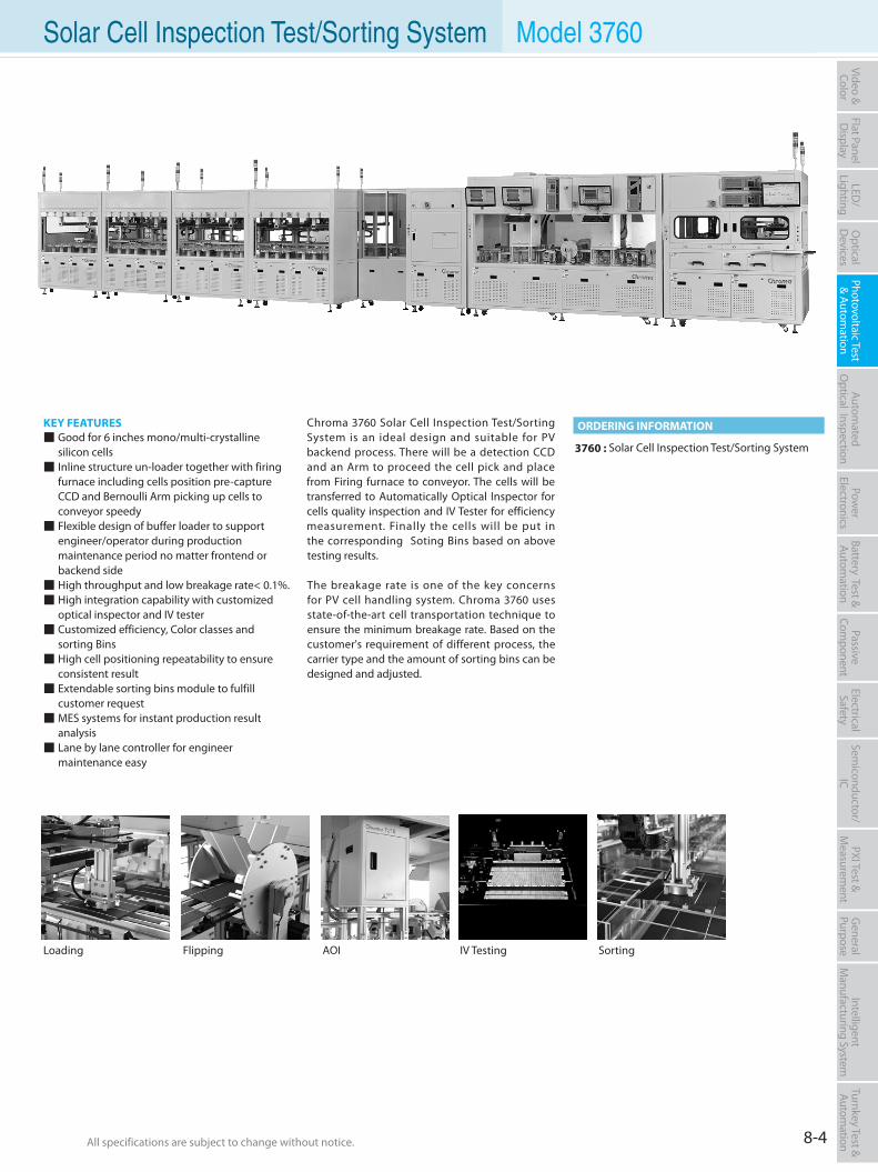
All specifications are subject to change without notice. All specifications are subject to change without notice. 8-4
Flat PanelD
isplayPow
er Electronics
Electrical Safety
General
PurposePassive
Component
Semiconductor/
ICBattery Test & Autom
ationAutom
atedO
ptical Inspection Photovoltaic Test
& Automation
PXI Test &
Measurem
ent Video & Color
LED/
LightingO
ptical D
evicesIntelligent
Manufacturing System
Turnkey Test & Autom
ation
KEY FEATURES Good for 6 inches mono/multi-crystalline silicon cells Inline structure un-loader together with firing furnace including cells position pre-capture CCD and Bernoulli Arm picking up cells to conveyor speedy Flexible design of buffer loader to support engineer/operator during production maintenance period no matter frontend or backend side High throughput and low breakage rate< 0.1%. High integration capability with customized optical inspector and IV tester Customized efficiency, Color classes and sorting Bins High cell positioning repeatability to ensure consistent result Extendable sorting bins module to fulfill customer request MES systems for instant production result analysis Lane by lane controller for engineer maintenance easy
3760 : Solar Cell Inspection Test/Sorting System
Chroma 3760 Solar Cell Inspection Test/Sorting System is an ideal design and suitable for PV backend process. There will be a detection CCD and an Arm to proceed the cell pick and place from Firing furnace to conveyor. The cells will be transferred to Automatically Optical Inspector for cells quality inspection and IV Tester for efficiency measurement. Finally the cells will be put in the corresponding Soting Bins based on above testing results.
The breakage rate is one of the key concerns for PV cell handling system. Chroma 3760 uses state-of-the-art cell transportation technique to ensure the minimum breakage rate. Based on the customer's requirement of different process, the carrier type and the amount of sorting bins can be designed and adjusted.
ORDERING INFORMATION
Loading Flipping IV Testing SortingAOI
Model 3760Solar Cell Inspection Test/Sorting System
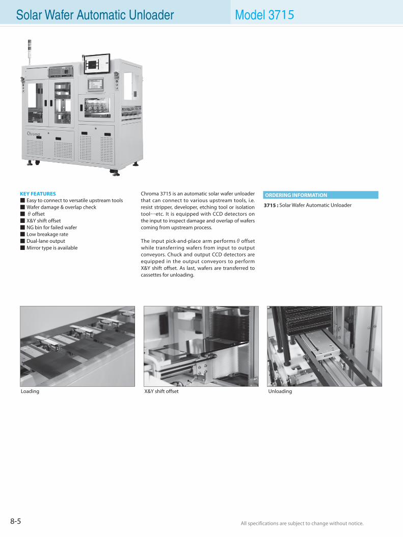
All specifications are subject to change without notice. All specifications are subject to change without notice.8-5
Solar Wafer Automatic Unloader Model 3715
KEY FEATURES Easy to connect to versatile upstream tools Wafer damage & overlap check θoffset X&Y shift offset NG bin for failed wafer Low breakage rate Dual-lane output Mirror type is available
3715 : Solar Wafer Automatic Unloader
Chroma 3715 is an automatic solar wafer unloader that can connect to various upstream tools, i.e. resist stripper, developer, etching tool or isolation tool⋯etc. It is equipped with CCD detectors on the input to inspect damage and overlap of wafers coming from upstream process.
The input pick-and-place arm performsθoffset while transferring wafers from input to output conveyors. Chuck and output CCD detectors are equipped in the output conveyors to perform X&Y shift offset. As last, wafers are transferred to cassettes for unloading.
ORDERING INFORMATION
Loading X&Y shift offset Unloading
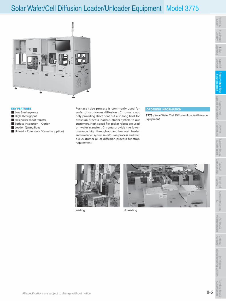
All specifications are subject to change without notice. All specifications are subject to change without notice. 8-6
Flat PanelD
isplayPow
er Electronics
Electrical Safety
General
PurposePassive
Component
Semiconductor/
ICBattery Test & Autom
ationAutom
atedO
ptical Inspection Photovoltaic Test
& Automation
PXI Test &
Measurem
ent Video & Color
LED/
LightingO
ptical D
evicesIntelligent
Manufacturing System
Turnkey Test & Autom
ation Model 3775
KEY FEATURES Low Breakage rate High Throughput Flex picker robot transfer Surface Inspection:Option Loader: Quartz Boat Unload:Coin stack / Cassette (option)
Furnace tube process is commonly used for wafer phosphorous diffusion . Chroma is not only providing short boat but also long boat for diffusion process loader/Unloder system to our customers. High speed flex picker robots are used on wafer transfer . Chroma provide the lower breakage, high throughout and low cost loader and unloader system in diffusion process and met our customer all of diffusion process function requirement.
3775 : Solar Wafer/Cell Diffusion Loader/Unloader Equipment
Loading Unloading
ORDERING INFORMATION
Solar Wafer/Cell Diffusion Loader/Unloader Equipment
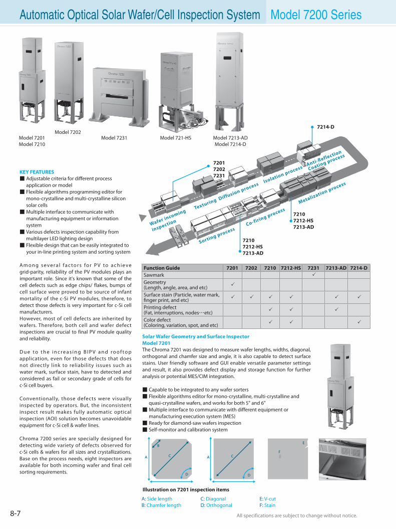
All specifications are subject to change without notice. All specifications are subject to change without notice.8-7
KEY FEATURES Adjustable criteria for different process application or model Flexible algorithms programming editor for mono-crystalline and multi-crystalline silicon solar cells Multiple interface to communicate with manufacturing equipment or information system Various defects inspection capability from multilayer LED lighting design Flexible design that can be easily integrated to your in-line printing system and sorting system
A m o n g s e ve r a l f a c t o r s fo r P V t o a c h i e ve grid-parity, reliability of the PV modules plays an important role. Since it's known that some of the cell defects such as edge chips/ flakes, bumps of cell surface were proved to be source of infant mortality of the c-Si PV modules, therefore, to detect those defects is very important for c-Si cell manufacturers.However, most of cell defects are inherited by wafers. Therefore, both cell and wafer defect inspections are crucial to final PV module quality and reliability.
D u e t o t h e i n c r e a s i n g B I P V a n d r o o f t o p application, even for those defects that does not directly link to reliability issues such as water mark, surface stain, have to detected and considered as fail or secondary grade of cells for c-Si cell buyers.
Conventionally, those defects were visually inspected by operators. But, the inconsistent inspect result makes fully automatic optical inspection (AOI) solution becomes unavoidable equipment for c-Si cell & wafer lines.
Chroma 7200 series are specially designed for detecting wide variety of defects observed for c-Si cells & wafers for all sizes and crystallizations. Base on the process needs, eight inspectors are available for both incoming wafer and final cell sorting requirements.
720172027231
Wafer incoming
inspection
Sorting processCo-firing process
Metalization process
Texturing Diffusion process Isolation process Anti-Reflection
Coating process
7214-D
72107212-HS7213-AD
72107212-HS7213-AD
Function Guide 7201 7202 7210 7212-HS 7231 7213-AD 7214-DSawmark
Geometry(Length, angle, area, and etc)
Surface stain (Particle, water mark, finger print, and etc)
Printing defect(Fat, interruptions, nodes⋯etc)
Color defect(Coloring, variation, spot, and etc)
Solar Wafer Geometry and Surface InspectorModel 7201The Chroma 7201 was designed to measure wafer lengths, widths, diagonal, orthogonal and chamfer size and angle, it is also capable to detect surface stains. User friendly software and GUI enable versatile parameter settings and result, it also provides defect display and storage function for further analysis or potential MES/CIM integration.
Capable to be integrated to any wafer sorters Flexible algorithms editor for mono-crystalline, multi-crystalline and quasi-crystalline wafers, and works for both 5" and 6" Multiple interface to communicate with different equipment or manufacturing execution system (MES) Ready for diamond-saw wafers inspection Self-monitor and calibration system
A: Side length B: Chamfer length
C: DiagonalD: Orthogonal
E: V-cutF: Stain
Illustration on 7201 inspection items
A C
D
B
A C
D
F
E
Automatic Optical Solar Wafer/Cell Inspection System Model 7200 Series
Model 7202Model 7231 Model 7213-AD
Model 7214-DModel 721-HSModel 7201
Model 7210
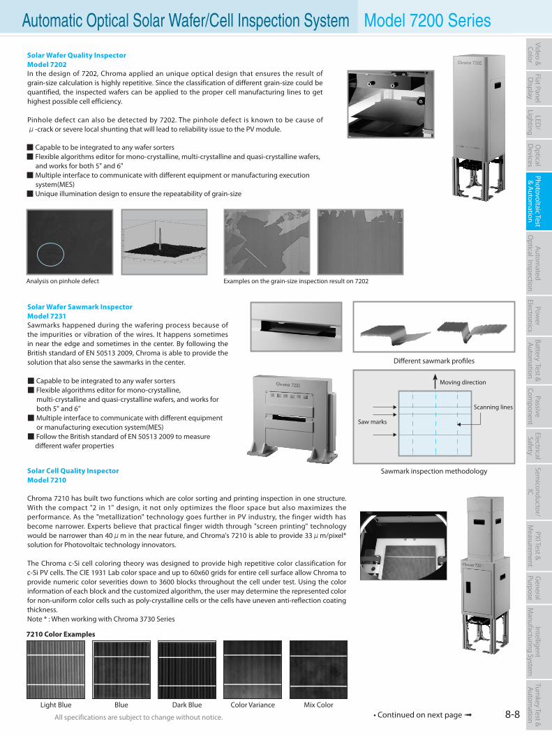
All specifications are subject to change without notice. All specifications are subject to change without notice. 8-8
Flat PanelD
isplayPow
er Electronics
Electrical Safety
General
PurposePassive
Component
Semiconductor/
ICBattery Test & Autom
ationAutom
atedO
ptical Inspection Photovoltaic Test
& Automation
PXI Test &
Measurem
ent Video & Color
LED/
LightingO
ptical D
evicesIntelligent
Manufacturing System
Turnkey Test & Autom
ation
Solar Cell Quality InspectorModel 7210
Chroma 7210 has built two functions which are color sorting and printing inspection in one structure. With the compact "2 in 1" design, it not only optimizes the floor space but also maximizes the performance. As the "metallization" technology goes further in PV industry, the finger width has become narrower. Experts believe that practical finger width through "screen printing" technology would be narrower than 40μm in the near future, and Chroma's 7210 is able to provide 33μm/pixel* solution for Photovoltaic technology innovators.
The Chroma c-Si cell coloring theory was designed to provide high repetitive color classification for c-Si PV cells. The CIE 1931 Lab color space and up to 60x60 grids for entire cell surface allow Chroma to provide numeric color severities down to 3600 blocks throughout the cell under test. Using the color information of each block and the customized algorithm, the user may determine the represented color for non-uniform color cells such as poly-crystalline cells or the cells have uneven anti-reflection coating thickness.Note * : When working with Chroma 3730 Series
Solar Wafer Quality InspectorModel 7202In the design of 7202, Chroma applied an unique optical design that ensures the result of grain-size calculation is highly repetitive. Since the classification of different grain-size could be quantified, the inspected wafers can be applied to the proper cell manufacturing lines to get highest possible cell efficiency.
Pinhole defect can also be detected by 7202. The pinhole defect is known to be cause of μ-crack or severe local shunting that will lead to reliability issue to the PV module.
Solar Wafer Sawmark InspectorModel 7231Sawmarks happened during the wafering process because of the impurities or vibration of the wires. It happens sometimes in near the edge and sometimes in the center. By following the British standard of EN 50513 2009, Chroma is able to provide the solution that also sense the sawmarks in the center.
Capable to be integrated to any wafer sorters Flexible algorithms editor for mono-crystalline, multi-crystalline and quasi-crystalline wafers, and works for both 5" and 6" Multiple interface to communicate with different equipment or manufacturing execution system(MES) Follow the British standard of EN 50513 2009 to measure different wafer properties
BlueLight Blue Dark Blue Color Variance Mix Color
Examples on the grain-size inspection result on 7202Analysis on pinhole defect
Different sawmark profiles
Sawmark inspection methodology
7210 Color Examples
Scanning lines
Moving direction
Saw marks
Automatic Optical Solar Wafer/Cell Inspection System Model 7200 Series
Capable to be integrated to any wafer sorters Flexible algorithms editor for mono-crystalline, multi-crystalline and quasi-crystalline wafers, and works for both 5" and 6" Multiple interface to communicate with different equipment or manufacturing execution system(MES) Unique illumination design to ensure the repeatability of grain-size
• Continued on next page
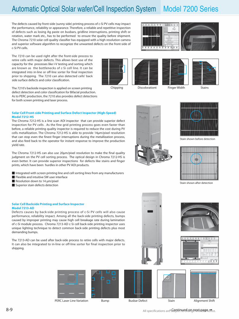
All specifications are subject to change without notice. All specifications are subject to change without notice.8-9
Automatic Optical Solar wafer/Cell Inspection System Model 7200 Series
The defects caused by front-side (sunny side) printing process of c-Si PV cells may impact the performance, reliability or appearance. Therefore, a reliable and repetitive inspection of defects such as losing Ag paste on busbars, gridline interruptions, printing shift or rotation, water mark etc., has to be performed to ensure the quality before shipment. The Chroma 7210 solar cell quality classifier has equipped with a high resolution camera and superior software algorithm to recognize the unwanted defects on the front-side of c-Si PV cells.
The 7210 can be used right after the front-side process to retire cells with major defects. This allows best use of the capacity for the processes like I-V testing and sorting which are known as the bottlenecks of c-Si cell line. It can be integrated into in-line or off-line sorter for final inspection prior to shipping. The 7210 can also detected cells' back side surface defects and color classification.
The 7210's backside inspection is applied on screen printing defect detection and color classification for Bifacial production. As to PERC production, the 7210 also provides defect detections for both screen printing and laser process.
Solar Cell Front-side Printing and Surface Defect Inspector (High-Speed)Model 7212-HSThe Chroma 7212-HS is a line scan AOI inspector that can provide superior defect inspection for PV cells . As the fine grid printing process goes even faster than before, a reliable printing quality inspector is required to reduce the cost during PV cells metallization. The Chroma 7212-HS is able to provide 14µm/pixel resolution that can stop even the finest finger interruptions during the metallization process, and also feed back to the operator for instant response to improve the production yield rate.
The Chroma 7212-HS can also use 20µm/pixel resolution to make the final quality judgment on the PV cell sorting process. The optical design in Chroma 7212-HS is even better. It can provide superior inspections for defects like stains and finger prints, which have been hurdles in other PV AOI products.
Integrated with screen printing line and cell sorting lines from any manufacturers Flexible and intuitive SW user interface Resolution down to 14 µm/pixel Superior stain defects detection
Chipping Discolorationt Finger Width Stains
Stain shown before detection
Stain shown after detection
• Continued on next page
Solar Cell Backside Printing and Surface InspectorModel 7213-ADDefects causes by back-side printing process of c-Si PV cells will also cause performance, reliability impact. Among all the back-side printing defects, bumps caused by improper printing may cause high cell breakage rate during lamination of c-Si module process. Chroma 7213-AD c-Si cell back-side printing inspector uses unique lighting technique to detect common back-side printing defects plus most demanding bumps. The 7213-AD can be used after back-side process to retire cells with major defects. It can also be integrated to in-line or off-line sorter for final inspection prior to shipping.
BumpPERC Laser Line Variation Busbar Defect Stain Alignment Shift
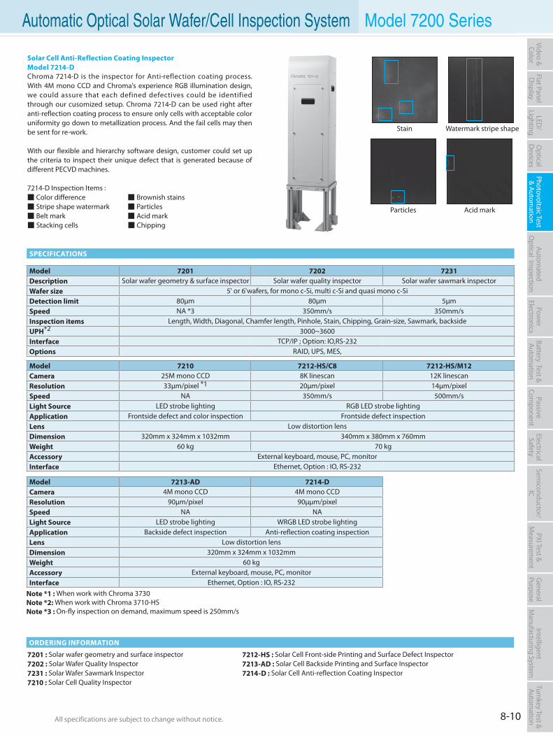
All specifications are subject to change without notice. All specifications are subject to change without notice. 8-10
Flat PanelD
isplayPow
er Electronics
Electrical Safety
General
PurposePassive
Component
Semiconductor/
ICBattery Test & Autom
ationAutom
atedO
ptical Inspection Photovoltaic Test
& Automation
PXI Test &
Measurem
ent Video & Color
LED/
LightingO
ptical D
evicesIntelligent
Manufacturing System
Turnkey Test & Autom
ation Automatic Optical Solar Wafer/Cell Inspection System Model 7200 Series
7201 : Solar wafer geometry and surface inspector7202 : Solar Wafer Quality Inspector7231 : Solar Wafer Sawmark Inspector7210 : Solar Cell Quality Inspector
7212-HS : Solar Cell Front-side Printing and Surface Defect Inspector 7213-AD : Solar Cell Backside Printing and Surface Inspector7214-D : Solar Cell Anti-reflection Coating Inspector
SPECIFICATIONS
ORDERING INFORMATION
Solar Cell Anti-Reflection Coating InspectorModel 7214-DChroma 7214-D is the inspector for Anti-reflection coating process. With 4M mono CCD and Chroma's experience RGB illumination design, we could assure that each defined defectives could be identified through our cusomized setup. Chroma 7214-D can be used right after anti-reflection coating process to ensure only cells with acceptable color uniformity go down to metallization process. And the fail cells may then be sent for re-work.
With our flexible and hierarchy software design, customer could set up the criteria to inspect their unique defect that is generated because of different PECVD machines.
7214-D Inspection Items : Color difference Brownish stains Stripe shape watermark Particles Belt mark Acid mark Stacking cells Chipping
Stain Watermark stripe shape
Particles Acid mark
Model 7201 7202 7231Description Solar wafer geometry & surface inspector Solar wafer quality inspector Solar wafer sawmark inspectorWafer size 5' or 6'wafers, for mono c-Si, multi c-Si and quasi mono c-SiDetection limit 80µm 80µm 5µmSpeed NA *3 350mm/s 350mm/sInspection items Length, Width, Diagonal, Chamfer length, Pinhole, Stain, Chipping, Grain-size, Sawmark, backsideUPH*2 3000~3600Interface TCP/IP ; Option: IO,RS-232Options RAID, UPS, MES,
Model 7210 7212-HS/C8 7212-HS/M12Camera 25M mono CCD 8K linescan 12K linescanResolution 33µm/pixel *1 20µm/pixel 14µm/pixelSpeed NA 350mm/s 500mm/sLight Source LED strobe lighting RGB LED strobe lightingApplication Frontside defect and color inspection Frontside defect inspectionLens Low distortion lensDimension 320mm x 324mm x 1032mm 340mm x 380mm x 760mmWeight 60 kg 70 kgAccessory External keyboard, mouse, PC, monitorInterface Ethernet, Option : IO, RS-232
Model 7213-AD 7214-DCamera 4M mono CCD 4M mono CCDResolution 90µm/pixel 90µµm/pixelSpeed NA NALight Source LED strobe lighting WRGB LED strobe lightingApplication Backside defect inspection Anti-reflection coating inspectionLens Low distortion lensDimension 320mm x 324mm x 1032mm Weight 60 kgAccessory External keyboard, mouse, PC, monitorInterface Ethernet, Option : IO, RS-232
Note *1 : When work with Chroma 3730Note *2: When work with Chroma 3710-HSNote *3 : On-fly inspection on demand, maximum speed is 250mm/s
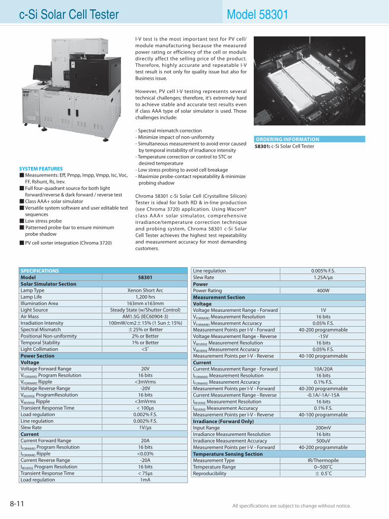
All specifications are subject to change without notice. All specifications are subject to change without notice.8-11
SYSTEM FEATURES Measurements: Eff, Pmpp, Impp, Vmpp, Isc, Voc,
FF, Rshunt, Rs, Irev. Full four-quadrant source for both light
forward/reverse & dark forward / reverse test Class AAA+ solar simulator Versatile system software and user editable test
sequences Low stress probe Patterned probe-bar to ensure minimum probe shadow
PV cell sorter integration (Chroma 3720)
58301: c-Si Solar Cell TesterORDERING INFORMATION
I-V test is the most important test for PV cell/module manufacturing because the measured power rating or efficiency of the cell or module directly affect the selling price of the product. Therefore, highly accurate and repeatable I-V test result is not only for quality issue but also for Business issue.
However, PV cell I-V testing represents several technical challenges; therefore, it's extremely hard to achieve stable and accurate test results even if class AAA type of solar simulator is used. Those challenges include:
- Spectral mismatch correction- Minimize impact of non-uniformity- Simultaneous measurement to avoid error caused by temporal instability of irradiance intensity- Temperature correction or control to STC or desired temperature- Low stress probing to avoid cell breakage- Maximize probe-contact repeatability & minimize probing shadow
Chroma 58301 c-Si Solar Cell (Crystalline Silicon) Tester is ideal for both RD & in-line production (see Chroma 3720) application. Using Wacom® class AAA+ solar simulator, comprehensive irradiance/temperature correction technique and probing system, Chroma 58301 c-Si Solar Cell Tester achieves the highest test repeatability and measurement accuracy for most demanding customers.
SPECIFICATIONSModel 58301Solar Simulator SectionLamp Type Xenon Short ArcLamp Life 1,200 hrsIllumination Area 163mm x163mmLight Source Steady State (w/Shutter Control)Air Mass AM1.5G (IEC60904-3)Irradiation Intensity 100mW/cm2±15% (1 Sun±15%)Spectral Mismatch ±25% or BetterPositional Non-uniformity 2% or BetterTemporal Stability 1% or BetterLight Collimation <5˚Power SectionVoltageVoltage Forward Range 20VVFORWARD Program Resolution 16 bitsVFORWARD Ripple <3mVrmsVoltage Reverse Range -20VVREVERSE ProgramResolution 16 bitsVREVERSE Ripple <3mVrmsTransient Response Time < 100µsLoad regulation 0.002% F.S.Line regulation 0.002% F.S.Slew Rate 1V/µsCurrentCurrent Forward Range 20AIFORWARD Program Resolution 16 bitsIFORWARD Ripple <0.03%Current Reverse Range -20AIREVERSE Program Resolution 16 bitsTransient Response Time < 75µsLoad regulation 1mA
Line regulation 0.005% F.S. Slew Rate 1.25A/µsPowerPower Rating 400WMeasurement SectionVoltageVoltage Measurement Range - Forward 1VVFORWARD Measurement Resolution 16 bitsVFORWARD Measurement Accuracy 0.05% F.S.Measurement Points per I-V - Forward 40-200 programmableVoltage Measurement Range - Reverse -15VVREVERSE Measurement Resolution 16 bitsVREVERSE Measurement Accuracy 0.05% F.S. Measurement Points per I-V - Reverse 40-100 programmableCurrentCurrent Measurement Range - Forward 10A/20AIFORWARD Measurement Resolution 16 bitsIFORWARD Measurement Accuracy 0.1% F.S.Measurement Points per I-V - Forward 40-200 programmableCurrent Measurement Range - Reverse -0.1A/-1A/-15AIREVERSE Measurement Resolution 16 bitsIREVERSE Measurement Accuracy 0.1% F.S. Measurement Points per I-V - Reverse 40-100 programmableIrradiance (Forward Only)Input Range 200mVIrradiance Measurement Resolution 16 bitsIrradiance Measurement Accuracy 500uVMeasurement Points per I-V - Forward 40-200 programmableTemperature Sensing SectionMeasurement Type IR/ThermopileTemperature Range 0~500˚CReproducibility ± 0.5˚C
c-Si Solar Cell Tester Model 58301
All specifications are subject to change without notice. All specifications are subject to change without notice. 8-12
Flat PanelD
isplayPow
er Electronics
Electrical Safety
General
PurposePassive
Component
Semiconductor/
ICBattery Test & Autom
ationAutom
atedO
ptical Inspection Photovoltaic Test
& Automation
PXI Test &
Measurem
ent Video & Color
LED/
LightingO
ptical D
evicesIntelligent
Manufacturing System
Turnkey Test & Autom
ation
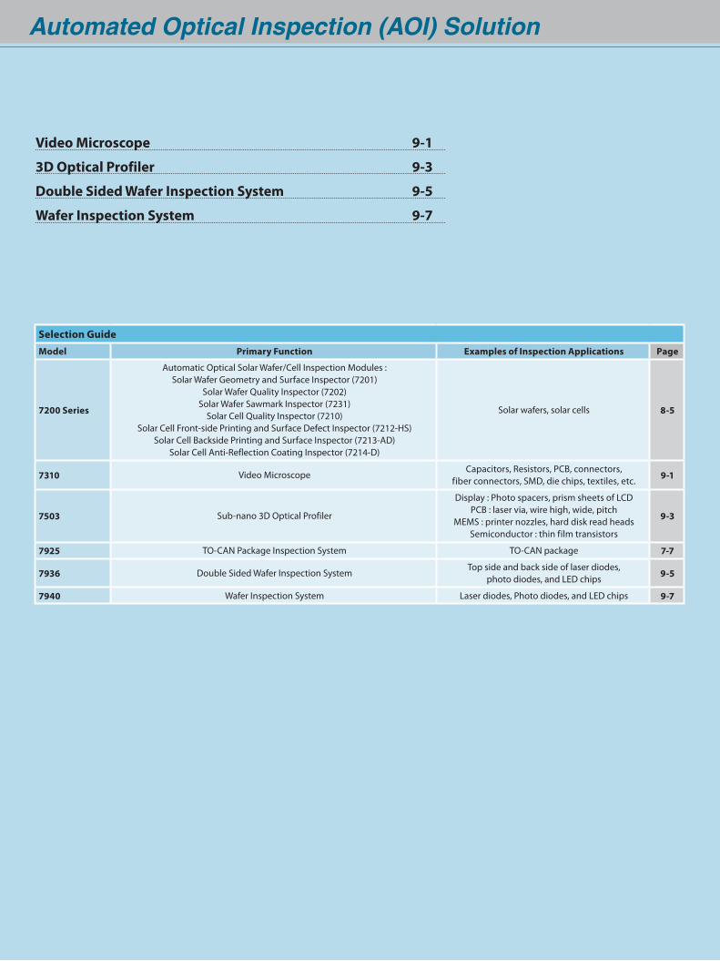
Video Microscope 9-1
3D Optical Profiler 9-3
Double Sided Wafer Inspection System 9-5
Wafer Inspection System 9-7
Automated Optical Inspection (AOI) Solution
Selection GuideModel Primary Function Examples of Inspection Applications Page
7200 Series
Automatic Optical Solar Wafer/Cell Inspection Modules : Solar Wafer Geometry and Surface Inspector (7201)
Solar Wafer Quality Inspector (7202)Solar Wafer Sawmark Inspector (7231)
Solar Cell Quality Inspector (7210)Solar Cell Front-side Printing and Surface Defect Inspector (7212-HS)
Solar Cell Backside Printing and Surface Inspector (7213-AD)Solar Cell Anti-Reflection Coating Inspector (7214-D)
Solar wafers, solar cells 8-5
7310 Video MicroscopeCapacitors, Resistors, PCB, connectors,
fiber connectors, SMD, die chips, textiles, etc. 9-1
7503 Sub-nano 3D Optical Profiler
Display : Photo spacers, prism sheets of LCDPCB : laser via, wire high, wide, pitch
MEMS : printer nozzles, hard disk read headsSemiconductor : thin film transistors
9-3
7925 TO-CAN Package Inspection System TO-CAN package 7-7
7936 Double Sided Wafer Inspection System Top side and back side of laser diodes,
photo diodes, and LED chips 9-5
7940 Wafer Inspection System Laser diodes, Photo diodes, and LED chips 9-7
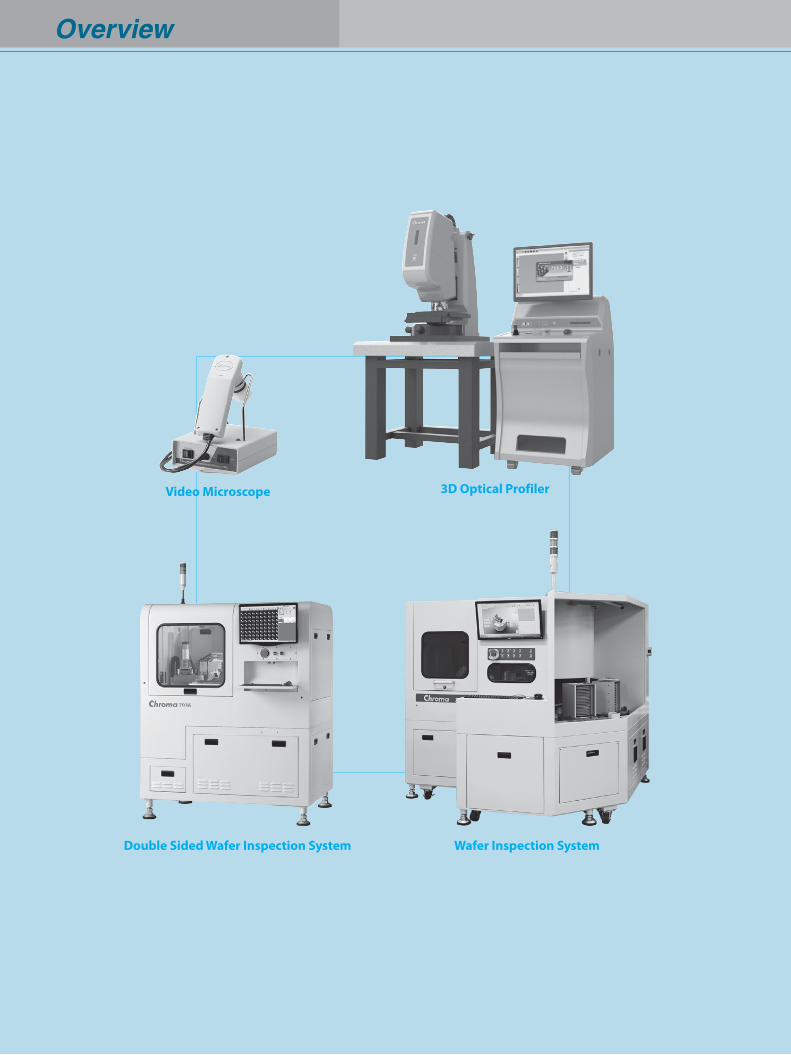
Video Microscope
Overview
Wafer Inspection SystemDouble Sided Wafer Inspection System
3D Optical Profiler
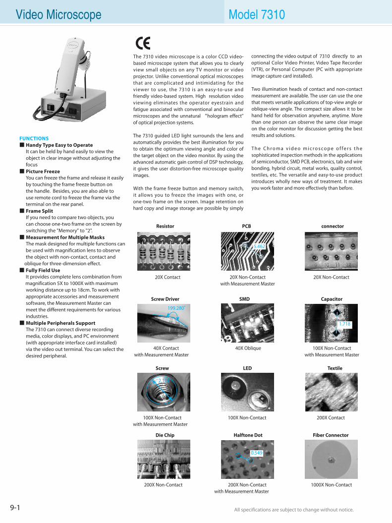
9-1 All specifications are subject to change without notice. All specifications are subject to change without notice.
FUNCTIONS Handy Type Easy to Operate It can be held by hand easily to view the
object in clear image without adjusting the focus Picture Freeze You can freeze the frame and release it easily
by touching the frame freeze button on the handle. Besides, you are also able to use remote cord to freeze the frame via the terminal on the rear panel. Frame Split If you need to compare two objects, you
can choose one-two frame on the screen by switching the "Memory" to "2". Measurement for Multiple Masks The mask designed for multiple functions can
be used with magnification lens to observe the object with non-contact, contact and oblique for three-dimension effect. Fully Field Use It provides complete lens combination from
magnification 5X to 1000X with maximum working distance up to 18cm. To work with appropriate accessories and measurement software, the Measurement Master can meet the different requirements for various industries. Multiple Peripherals Support The 7310 can connect diverse recording
media, color displays, and PC environment (with appropriate interface card installed) via the video out terminal. You can select the desired peripheral.
The 7310 video microscope is a color CCD video-based microscope system that allows you to clearly view small objects on any TV monitor or video projector. Unlike conventional optical microscopes that are complicated and intimidating for the viewer to use, the 7310 is an easy-to-use and friendly video-based system. High resolution video viewing eliminates the operator eyestrain and fatigue associated with conventional and binocular microscopes and the unnatural “hologram effect" of optical projection systems.
The 7310 guided LED light surrounds the lens and automatically provides the best illumination for you to obtain the optimum viewing angle and color of the target object on the video monitor. By using the advanced automatic gain control of DSP technology, it gives the user distortion-free microscope quality images.
With the frame freeze button and memory switch, it allows you to freeze the images with one, or one-two frame on the screen. Image retention on hard copy and image storage are possible by simply
connecting the video output of 7310 directly to an optional Color Video Printer, Video Tape Recorder (VTR), or Personal Computer (PC with appropriate image capture card installed).
Two illumination heads of contact and non-contact measurement are available. The user can use the one that meets versatile applications of top-view angle or oblique-view angle. The compact size allows it to be hand held for observation anywhere, anytime. More than one person can observe the same clear image on the color monitor for discussion getting the best results and solutions.
T h e C h r o m a v i d e o m i c r o s c o p e o f f e r s t h e sophisticated inspection methods in the applications of semiconductor, SMD PCB, electronics, tab and wire bonding, hybrid circuit, metal works, quality control, textiles, etc. The versatile and easy-to-use product introduces wholly new ways of treatment. It makes you work faster and more effectively than before.
Resistor PCB connector
Screw Driver SMD Capacitor
Screw LED Textile
Die Chip Halftone Dot Fiber Connector
20X Contact 20X Non-Contactwith Measurement Master
20X Non-Contact
40X Contactwith Measurement Master
40X Oblique 100X Non-Contactwith Measurement Master
100X Non-Contactwith Measurement Master
100X Non-Contact 200X Contact
5.462
199.280˚
2.118
0.549
1.718
200X Non-Contact 200X Non-Contactwith Measurement Master
1000X Non-Contact
Video Microscope Model 7310
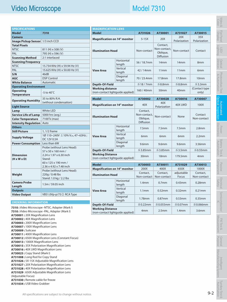
9-2All specifications are subject to change without notice. All specifications are subject to change without notice.
Flat PanelD
isplayPow
er Electronics
Electrical Safety
General
PurposePassive
Component
Semiconductor/
ICBattery Test & Autom
ationAutom
atedO
ptical Inspection Photovoltaic Test
& Automation
PXI Test &
Measurem
ent Video & Color
LED/
LightingO
ptical D
evicesIntelligent
Manufacturing System
Turnkey Test & Autom
ation
7310 : Video Microscope -NTSC, Adapter (Mark I)7310 : Video Microscope -PAL, Adapter (Mark I)A730001 : 20X Magnification LensA730002 : 40X Magnification LensA730003 : 200X Magnification LensA730007 : 100X Magnification LensA730009 : SuitcaseA730011 : 400X Magnification LensA730012 : 650X Magnification Lens (Constant Focus)A730013 : 1000X Magnification LensA730015 : 35X Polarization Magnification LensA730016 : 40X LWD Magnification LensA730025 : Copy Stand (Mark I)A731008 : Long Rod for Copy StandA731026 : 5X-15X Adjustable Magnification LensA731027 : 20X Polarization Magnification LensA731028 : 40X Polarization Magnification LensA731029 : 650X Adjustable Magnification Lens (Adjustable Focus)A731030 : Remote cable for freezeA731034 : USB Video Grabber
SPECIFICATIONSModel 7310CameraImage Pickup Sensor 1/3 inch CCDTotal PixelsNTSC 811 (H) x 508 (V)PAL 795 (H) x 596 (V)Scanning Method 2:1 interlacedScanning FrequencyNTSC 15.734 KHz (H) x 59.94 Hz (V)PAL 15.625 KHz (H) x 50.00 Hz (V)S/N 46dBAGC DSP ControlWhite Balance AutomaticOperating EnvironmentOperating Temperature
-5 to 40˚C
Operating Humidity 35 to 80% R.H. (without condensation)
Light SourceLamp White LEDService Life of Lamp 5000 hrs (avg.)Color Temperature 7100˚k (max)Intensity Regulation AutoOthersStill Picture 1, 1/2 frame
Supply Voltage 1Ø 110~240V ±10% VLN, 47~63Hz ; DC 12V 0.5A
Power Consumption Less than 6W
Dimension(H x W x D)
Probe (without Lens Head):57 x 50 x 160 mm / 2.24 x 1.97 x 6.30 inchStand:60 x 125 x 190 mm / 2.36 x 4.92 x 7.48 inch
Weight Probe (without Lens Head): 220g / 0.48 lbsStand: 1.0 kg / 2.2 lbs
Camera Probe Length
1.5m / 59.05 inch
OutputsVideo Output VBS1.0Vp-p/75Ω RCA Type
MAGNIFICATION LENSModel A731026 A730001 A731027 A730015
Magnification on 14" monitor 5-15X 20X20X
Polarization 35X
Polarization
Illumination Head Non-contact
Contact, Non-contact,
Oblique, Diffusion
Non-contact Contact
View Area
Horizontal length
56 / 18.7mm 14mm 14mm 8mm
Vertical length
42 / 14mm 11mm 11mm 6mm
Diagonal length
70 / 23.4mm 17.8mm 17.8mm 10mm
Depth-Of-Field ≦18 / 7mm ≦8.8mm ≦8.8mm ≦3.3mmWorking distance (non-contact lightguide applied)
160 / 40mm 50mm 40mm (Contact type
only)
Model A730002 A730028 A730016 A730007
Magnification on 14" monitor 40X 40X
Polarization40X LWD 100X
Illumination Head
Contact, Non-contact,
Oblique, Diffusion
Non-contact None Contact
Non-contact
View Area
Horizontal length
7.5mm 7.5mm 7.5mm 2.8mm
Vertical length
6mm 6mm 6mm 2.2mm
Diagonal length
9.6mm 9.6mm 9.6mm 3.56mm
Depth-Of-Field ≦3.85mm ≦3.85mm ≦3.5mm ≦0.55mmWorking Distance (non-contact lightguide applied)
30mm 18mm 179.5mm 4mm
Model A730003 A730011 A731029 A730013Magnification on 14" monitor 200X 400X 650X 1000X
Illumination Head Contact,
Non-contactContact,
Non-contactadjustable
FocusContact,
Non-contact
View Area
Horizontal length
1.4mm 0.7mm 0.43mm 0.28mm
Vertical length
1.1mm 0.52mm 0.32mm 0.21mm
Diagonal length
1.78mm 0.87mm 0.53mm 0.35mm
Depth-Of-Field ≦0.22mm ≦0.055mm ≦0.07mm ≦0.066mmWorking Distance(non-contact lightguide applied)
4mm 2.5mm 1.4mm 3.6mm
Video Microscope Model 7310
ORDERING INFORMATION
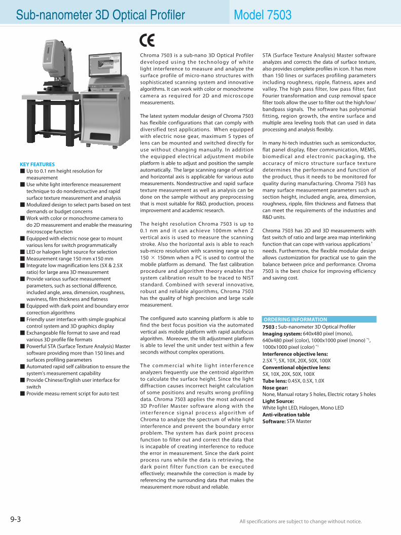
9-3 All specifications are subject to change without notice. All specifications are subject to change without notice.
Sub-nanometer 3D Optical Profiler Model 7503
7503 : Sub-nanometer 3D Optical Profiler Imaging system: 640x480 pixel (mono), 640x480 pixel (color), 1000x1000 pixel (mono) *1, 1000x1000 pixel (color) *1 Interference objective lens:2.5X *2, 5X, 10X, 20X, 50X, 100X Conventional objective lens:5X, 10X, 20X, 50X, 100X Tube lens: 0.45X, 0.5X, 1.0X Nose gear:None, Manual rotary 5 holes, Electric rotary 5 holes Light Source:White light LED, Halogen, Mono LED Anti-vibration table Software: STA Master
ORDERING INFORMATION
STA (Surface Texture Analysis) Master software analyzes and corrects the data of surface texture, also provides complete profiles in icon. It has more than 150 lines or surfaces profiling parameters including roughness, ripple, flatness, apex and valley. The high pass filter, low pass filter, fast Fourier transformation and cusp removal space filter tools allow the user to filter out the high/low/ bandpass signals. The software has polynomial fitting, region growth, the entire surface and multiple area leveling tools that can used in data processing and analysis flexibly.
In many hi-tech industries such as semiconductor, flat panel display, fiber communication, MEMS, biomedical and elec tronic pack aging, the accuracy of micro structure sur face texture determines the performance and function of the product, thus it needs to be monitored for quality during manufacturing. Chroma 7503 has many surface measurement parameters such as section height, included angle, area, dimension, roughness, ripple, film thickness and flatness that can meet the requirements of the industries and R&D units.
Chroma 7503 has 2D and 3D measurements with fast switch of ratio and large area map interlinking function that can cope with various applications’ needs. Furthermore, the flexible modular design allows customization for practical use to gain the balance between price and performance. Chroma 7503 is the best choice for improving efficiency and saving cost.
KEY FEATURES Up to 0.1 nm height resolution for measurement Use white light interference measurement technique to do nondestructive and rapid surface texture measurement and analysis Modulized design to select parts based on test demands or budget concerns Work with color or monochrome camera to do 2D measurement and enable the measuring microscope function Equipped with electric nose gear to mount various lens for switch programmatically LED or halogen light source for selection Measurement range 150 mm x150 mm Integrate low magnification lens (5X & 2.5X ratio) for large area 3D measurement Provide various surface measurement parameters, such as sectional difference, included angle, area, dimension, roughness, waviness, film thickness and flatness Equipped with dark point and boundary error correction algorithms Friendly user interface with simple graphical control system and 3D graphics display Exchangeable file format to save and read various 3D profile file formats Powerful STA (Surface Texture Analysis) Master software providing more than 150 lines and surfaces profiling parameters Automated rapid self calibration to ensure the system's measurement capability Provide Chinese/English user interface for switch Provide measu rement script for auto test
Chroma 7503 is a sub-nano 3D Optical Profiler developed using the technology of white light interference to measure and analyze the surface profile of micro-nano structures with sophisticated scanning system and innovative algorithms. It can work with color or monochrome camera as required for 2D and microscope measurements.
The latest system modular design of Chroma 7503 has flexible configurations that can comply with diversified test applications. When equipped with electric nose gear, maximum 5 types of lens can be mounted and switched directly for use without changing manually. In addition the equipped electrical adjustment mobile platform is able to adjust and position the sample automatically. The large scanning range of vertical and horizontal axis is applicable for various auto measurements. Nondestructive and rapid surface texture measurement as well as analysis can be done on the sample without any preprocessing that is most suitable for R&D, production, process improvement and academic research.
The height resolution Chroma 7503 is up to 0.1 nm and i t can achieve 100mm when Z vertical axis is used to measure the scanning stroke. Also the horizontal axis is able to reach sub-micro resolution with scanning range up to 150 × 150mm when a PC is used to control the mobile platform as demand. The fast calibration procedure and algorithm theory enables the system calibration result to be traced to NIST standard. Combined with several innovative, robust and reliable algorithms, Chroma 7503 has the quality of high precision and large scale measurement.
The configured auto scanning platform is able to find the best focus position via the automated vertical axis mobile platform with rapid autofocus algorithm. Moreover, the tilt adjustment platform is able to level the unit under test within a few seconds without complex operations.
Th e co m m e rc i a l w h i te l i g h t i n te r fe re n ce analyzers frequently use the centroid algorithm to calculate the surface height. Since the light diffraction causes incorrect height calculation of some positions and results wrong profiling data. Chroma 7503 applies the most advanced 3D Profiler Master software along with the i n te r fe re n ce s i g n a l p ro ce s s a l g o r i t h m o f Chroma to analyze the spectrum of white light interference and prevent the boundary error problem. The system has dark point process function to filter out and correct the data that is incapable of creating interference to reduce the error in measurement. Since the dark point process runs while the data is retrieving, the dark point f i lter function can be executed effectively; meanwhile the correction is made by referencing the surrounding data that makes the measurement more robust and reliable.
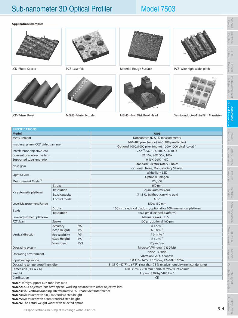
9-4All specifications are subject to change without notice. All specifications are subject to change without notice.
Flat PanelD
isplayPow
er Electronics
Electrical Safety
General
PurposePassive
Component
Semiconductor/
ICBattery Test & Autom
ationAutom
atedO
ptical Inspection Photovoltaic Test
& Automation
PXI Test &
Measurem
ent Video & Color
LED/
LightingO
ptical D
evicesIntelligent
Manufacturing System
Turnkey Test & Autom
ation Sub-nanometer 3D Optical Profiler Model 7503
LCD-Photo Spacer
SPECIFICATIONSModel 7503Measurement Noncontact 3D & 2D measurements
Imaging system (CCD video camera)640x480 pixel (mono), 640x480 pixel (color)
Optional 1000x1000 pixel (mono), 1000x1000 pixel (color) *1
Interference objective lens 2.5X *2, 5X, 10X, 20X, 50X, 100XConventional objective lens 5X, 10X, 20X, 50X, 100XSupported tube lens ratio 0.45X, 0.5X, 1.0X
Nose gearStandard : Electric rotary 5 holes
Optional : None, Manual rotary 5 holes
Light SourceWhite light LED
Optional HalogenMeasurement Mode *3 PSI, VSI
XY automatic platform
Stroke 150 mm Resolution 2 µm (auto version) Load capacity ≦1.1 Kg (without carrying tray) Control mode Auto
Level Measurement Range 150 x 150 mm
Z axis Stroke 100 mm electrical platform, optional for 100 mm manual platform Resolution < 0.5 µm (Electrical platform)
Level adjustment platform Manual 2 axes , ± 6°PZT Scan Stroke 100 µm, optional 400 µm
Vertical direction
Accuracy(Step Height)
VSI ≦1.5 % *4
PSI ≦5.0 % *5
Repeatability (Step Height)
VSI ≦0.14 % *4
PSI ≦1.7 % *5
Scan speed PZT 12 µm / secOperating system Microsoft Window® 7 (32-bit)
Operating environmentNoise : ≤ 60db
Vibration : VC-C or aboveInput voltage range 1Ø 110~240V ±10% VLN, 47~63Hz, 50VAOperating temperature/ humidity 15~35 (47 to 67) ; less than 75 % relative humidity (non condensing)Dimension (H x W x D) 1800 x 760 x 760 mm / 70.87 x 29.92 x 29.92 inchWeight Approx. 220 Kg / 485 lbs *6
Certification CE
Note*1: Only support 1.0X tube lens ratioNote*2: 2.5X objective lens have special working distance with other objective lensNote*3: VSI: Vertical Scanning Interferometry; PSI: Phase Shift InterferenceNote*4: Measured with 8.0μm standard step heightNote*5: Measured with 46nm standard step heightNote*6: The actual weight varies with selected option
Application Examples
LCD-Prism Sheet
PCB-Laser Via
MEMS-Printer Nozzle MEMS-Hard Disk Read Head Semiconductor-Thin Film Transistor
Material-Rough Surface PCB-Wire high, wide, pitch
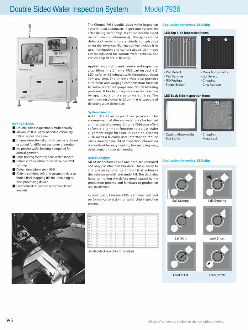
9-5 All specifications are subject to change without notice. All specifications are subject to change without notice.
Double Sided Wafer Inspection System Model 7936
KEY FEATURES Double-sided inspection simultaneously Maximum 8 in. wafer handling capability (10 in. inspection area) Unique detection algorithm can be replaced or added for different customer or product No precise wafer loading is required for auto alignment Edge finding to test various wafer shapes Defect criteria editor for versatile pass/fail settings Defect detection rate > 99% Able to combine AOI and upstream data to form a final mapping file for uploading to next processing device Customized inspection report for defect analysis
The Chroma 7936 double sided wafer inspection system is an automatic inspection system for after-dicing wafer chip. It can do double sided inspection simultaneously. The appearance defects of wafer chip are clearly conspicuous when the advanced illumination technology is in use. Illumination and camera acquisition mode can be adjusted for various wafer process, like vertical chip, VCSEL or flip chip.
Applied with high speed camera and inspection algorithms, the Chroma 7936 can inspect a 2" LED wafer in 4.5 minutes with throughput about 35msec/ chip. The Chroma 7936 also provides auto focus and warpage compensation function to solve wafer warpage and chuck leveling problems. It has two magnifications for selection by applicable chip size or defect s ize. The minimum resolution is 0.7um that is capable of detecting 2 um defect size.
System FunctionA f t e r t h e t a p e e x p a n s i o n p r o c e s s , t h e arrangement of dies on wafer may be formed an irregular alignment. Chroma 7936 also offers software alignment function to adjust wafer alignment angle for scan. In addition, Chroma 7936 owns a friendly user interface to reduce user's learning time. All of inspection information is visualized for easy reading, like mapping map, defect region, inspection results.
Defect AnalysisAll of inspection result raw data are recorded not only pass/fail and bin data. This is easily to analysis an optimal parameter that achieves the balance overkill and underkill. The data also helps to monitor the defect trend caused by the production process, and feedback to production unit in advance.
In conclusion, Chroma 7936 is an ideal cost and performance selection for wafer chip inspection process.
Detail defect raw data for analysis
Application for vertical LED chip
LED Top Side Inspection Items
LED Back Side Inspection Items
- Pad Defect- Pad Residue- ITO Peeling- Finger Broken
- Cutting Abnormality- Pad Bump
- Mesa Abnormality- Epi Defect- Chipping- Chip Residue
- Chipping- Metal Lack
Application for vertical LED chip
Ball Missing Ball Chipping
Ball Shift Lead Short
Lead oPEN Lead Notch
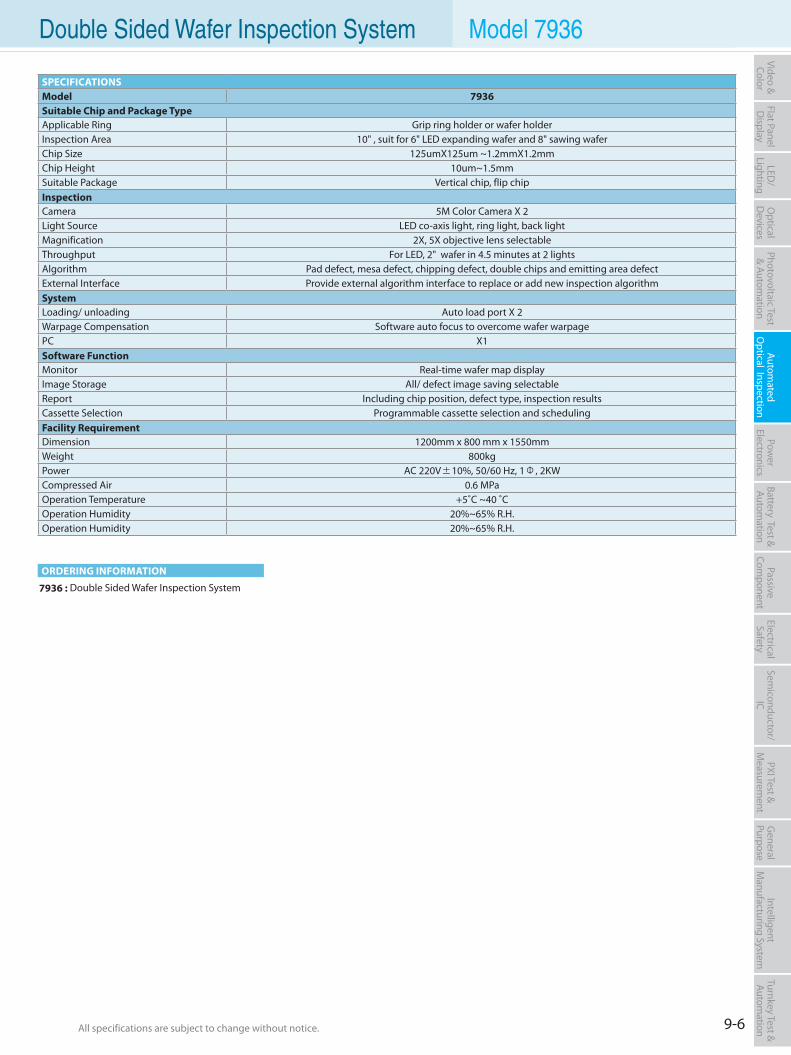
9-6All specifications are subject to change without notice. All specifications are subject to change without notice.
Flat PanelD
isplayPow
er Electronics
Electrical Safety
General
PurposePassive
Component
Semiconductor/
ICBattery Test & Autom
ationAutom
atedO
ptical Inspection Photovoltaic Test
& Automation
PXI Test &
Measurem
ent Video & Color
LED/
LightingO
ptical D
evicesIntelligent
Manufacturing System
Turnkey Test & Autom
ation Double Sided Wafer Inspection System Model 7936
7936 : Double Sided Wafer Inspection System
ORDERING INFORMATION
SPECIFICATIONSModel 7936Suitable Chip and Package TypeApplicable Ring Grip ring holder or wafer holderInspection Area 10" , suit for 6" LED expanding wafer and 8" sawing waferChip Size 125umX125um ~1.2mmX1.2mmChip Height 10um~1.5mmSuitable Package Vertical chip, flip chipInspectionCamera 5M Color Camera X 2Light Source LED co-axis light, ring light, back lightMagnification 2X, 5X objective lens selectableThroughput For LED, 2" wafer in 4.5 minutes at 2 lightsAlgorithm Pad defect, mesa defect, chipping defect, double chips and emitting area defectExternal Interface Provide external algorithm interface to replace or add new inspection algorithmSystemLoading/ unloading Auto load port X 2Warpage Compensation Software auto focus to overcome wafer warpagePC X1Software FunctionMonitor Real-time wafer map displayImage Storage All/ defect image saving selectableReport Including chip position, defect type, inspection resultsCassette Selection Programmable cassette selection and schedulingFacility RequirementDimension 1200mm x 800 mm x 1550mmWeight 800kgPower AC 220V±10%, 50/60 Hz, 1Φ, 2KWCompressed Air 0.6 MPaOperation Temperature +5˚C ~40 ˚COperation Humidity 20%~65% R.H.Operation Humidity 20%~65% R.H.
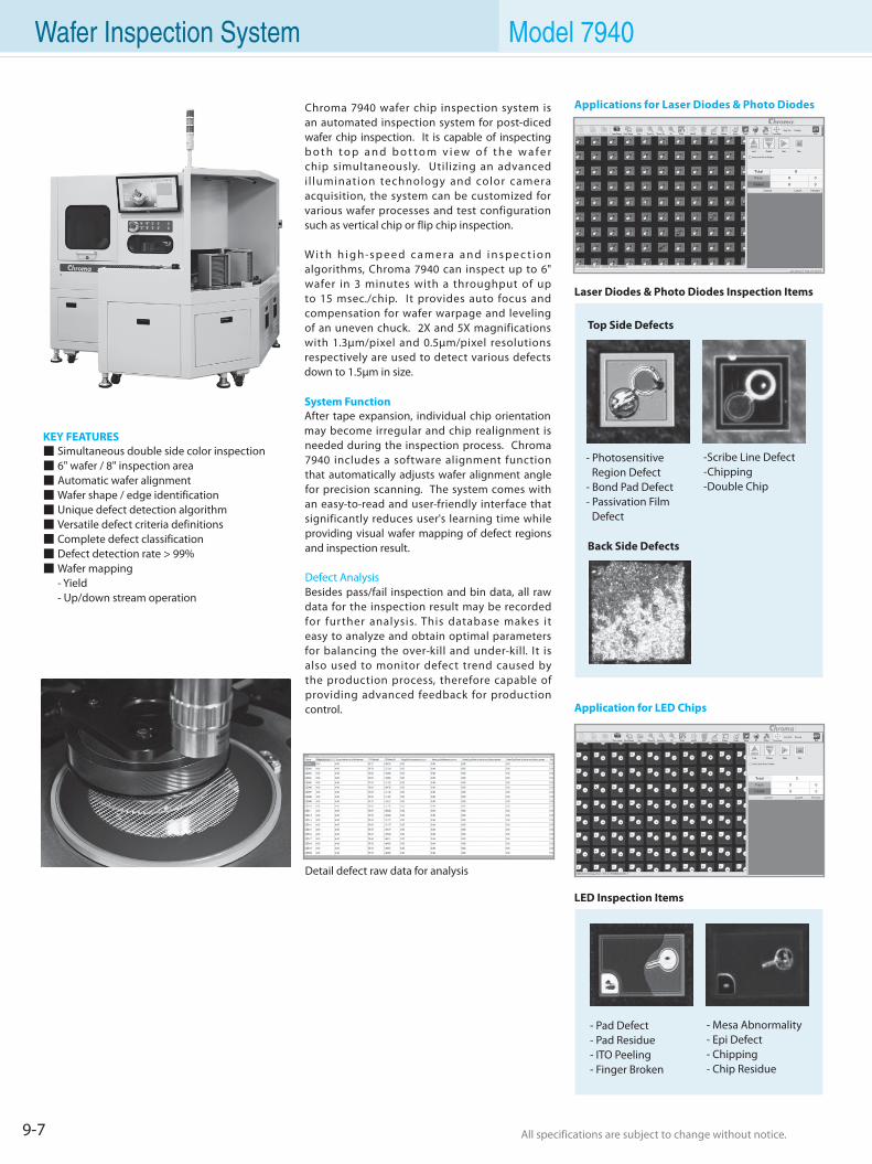
9-7 All specifications are subject to change without notice. All specifications are subject to change without notice.
Wafer Inspection System Model 7940
KEY FEATURES Simultaneous double side color inspection 6" wafer / 8" inspection area Automatic wafer alignment Wafer shape / edge identification Unique defect detection algorithm Versatile defect criteria definitions Complete defect classification Defect detection rate > 99% Wafer mapping - Yield - Up/down stream operation
Chroma 7940 wafer chip inspection system is an automated inspection system for post-diced wafer chip inspection. It is capable of inspecting b o t h t o p a n d b o t t o m v i e w o f t h e w a f e r chip simultaneously. Utilizing an advanced i l lumination technology and color camera acquisition, the system can be customized for various wafer processes and test configuration such as vertical chip or flip chip inspection.
Wi t h h i g h-s p e e d c a m e r a a n d i n s p e c t i o n algorithms, Chroma 7940 can inspect up to 6" wafer in 3 minutes with a throughput of up to 15 msec./chip. It provides auto focus and compensation for wafer warpage and leveling of an uneven chuck. 2X and 5X magnifications with 1.3µm/pixel and 0.5µm/pixel resolutions respectively are used to detect various defects down to 1.5µm in size.
System FunctionAfter tape expansion, individual chip orientation may become irregular and chip realignment is needed during the inspection process. Chroma 7940 includes a software alignment function that automatically adjusts wafer alignment angle for precision scanning. The system comes with an easy-to-read and user-friendly interface that significantly reduces user's learning time while providing visual wafer mapping of defect regions and inspection result.
Defect AnalysisBesides pass/fail inspection and bin data, all raw data for the inspection result may be recorded for further analysis. This database makes it easy to analyze and obtain optimal parameters for balancing the over-kill and under-kill. It is also used to monitor defect trend caused by the production process, therefore capable of providing advanced feedback for production control.
Detail defect raw data for analysis
-Scribe Line Defect-Chipping-Double Chip
- Photosensitive Region Defect- Bond Pad Defect- Passivation Film Defect
- Mesa Abnormality- Epi Defect- Chipping- Chip Residue
- Pad Defect- Pad Residue- ITO Peeling- Finger Broken
LED Inspection Items
Application for LED Chips
Applications for Laser Diodes & Photo Diodes
Laser Diodes & Photo Diodes Inspection Items
Top Side Defects
Back Side Defects
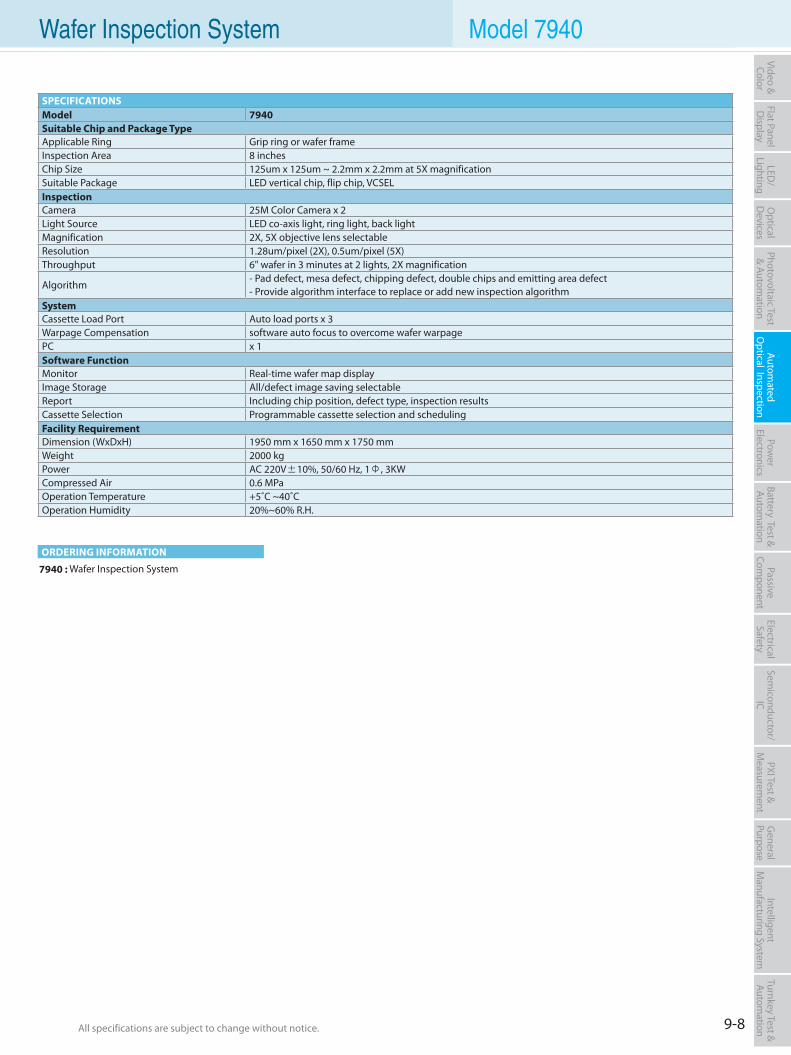
9-8All specifications are subject to change without notice. All specifications are subject to change without notice.
Flat PanelD
isplayPow
er Electronics
Electrical Safety
General
PurposePassive
Component
Semiconductor/
ICBattery Test & Autom
ationAutom
atedO
ptical Inspection Photovoltaic Test
& Automation
PXI Test &
Measurem
ent Video & Color
LED/
LightingO
ptical D
evicesIntelligent
Manufacturing System
Turnkey Test & Autom
ation Wafer Inspection System Model 7940
7940 : Wafer Inspection System
ORDERING INFORMATION
SPECIFICATIONSModel 7940Suitable Chip and Package TypeApplicable Ring Grip ring or wafer frameInspection Area 8 inchesChip Size 125um x 125um ~ 2.2mm x 2.2mm at 5X magnificationSuitable Package LED vertical chip, flip chip, VCSELInspectionCamera 25M Color Camera x 2Light Source LED co-axis light, ring light, back lightMagnification 2X, 5X objective lens selectableResolution 1.28um/pixel (2X), 0.5um/pixel (5X)Throughput 6" wafer in 3 minutes at 2 lights, 2X magnification
Algorithm- Pad defect, mesa defect, chipping defect, double chips and emitting area defect- Provide algorithm interface to replace or add new inspection algorithm
SystemCassette Load Port Auto load ports x 3Warpage Compensation software auto focus to overcome wafer warpagePC x 1Software FunctionMonitor Real-time wafer map displayImage Storage All/defect image saving selectableReport Including chip position, defect type, inspection resultsCassette Selection Programmable cassette selection and schedulingFacility RequirementDimension (WxDxH) 1950 mm x 1650 mm x 1750 mmWeight 2000 kgPower AC 220V±10%, 50/60 Hz, 1Φ, 3KWCompressed Air 0.6 MPaOperation Temperature +5˚C ~40˚COperation Humidity 20%~60% R.H.
Selection Guides 10-1
DC Electronic Load 10-5
AC Electronic Load 10-40
AC Power Source 10-42
Digital Power Meter 10-58
DC Power Supply 10-62
Automatic Test System 10-78
Power Electronics & Electric Vehicle Test Solution
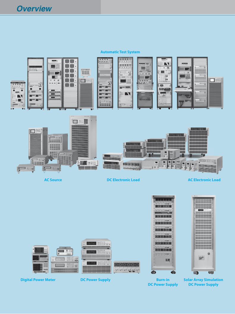
Overview
DC Power Supply
Automatic Test System
Burn-inDC Power Supply
AC Electronic LoadAC Source DC Electronic Load
Digital Power Meter Solar Array SimulationDC Power Supply
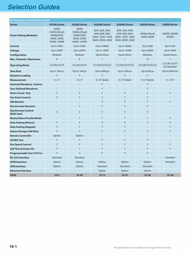
Selection Guides
All specifications are subject to change without notice. All specifications are subject to change without notice.10-1
DC Electronic Load Selection Guide
Series 6310A Series 6330A Series 63200A Series 63200E Series 63600 Series 63800 Series
Power Rating (Modular)
200W, 100Wx2(Dual),
30W&250W, 300W, 350W, 600W, 1200W
200W, 100Wx2(Dual)
30W&250W, 300W, 350W, 600W, 1200W
2kW, 3kW, 4kW, 5kW, 6kW, 8kW,
10kW, 12kW, 15kW, 18kW, 20kW, 24kW
2kW, 3kW, 4kW, 5kW, 6kW, 8kW,
10kW, 12kW, 15kW, 18kW, 20kW, 24kW
100Wx2(Dual),300W, 400W
1800W, 3600W, 4500W
Current Up to 240A Up to 240A Up to 2000A Up to 2000A Up to 80A Up to 45A
Voltage Up to 600V Up to 600V Up to 1200V Up to 1200V Up to 600V Up to 500V
Configuration Modular Modular Stand-Alone Stand-Alone Modular Stand-Alone
Max. Channel / Mainframe 8 8 1 1 10 1
Operating Mode CC/CR/CV/CP CC/CR/CV/CP CC/CR/CV/CP/CZ CC/CR/CV/CP/CZ CC/CR/CV/CP/CZCC/CR/CV/CP/DC Rectified
Slew Rate Up to 10A/µs Up to 10A/µs Up to 80A/µs Up to 20A/µs Up to 8A/µs Up to 600A/ms
Dynamic Loading Y Y Y Y Y -
Measurement V, I, P V, I, P V, I, P, Vpeak V, I, P, Vpeak V, I, P, Vpeak V, I, P, R
External Waveform Control - - Y - Y -
User Defined Waveform - - Y - Y -
Short Circuit Test Y Y Y Y Y Y
Von Point Control Y Y Y Y Y -
V&I Monitor - - Y Y Y Y
Synchronize Dynamic - Y Y Y Y -
Synchronize Control Multi-load
Y Y Y Y Y -
Master/Slave Parallel Mode - Y Y Y Y Y
Data Setting (Rotary) Y Y Y Y Y Y
Data Setting (Keypad) Y Y Y Y - Y
Status Storage (100 files) Y Y Y Y Y Y
Remote Controller Option Option - - - -
GO/NG Test Y Y Y Y Y -
Fan Speed Control Y Y Y Y Y Y
Self Test at Power On Y Y Y Y Y Y
Programmable Test (10 Pro.) Y Y Y Y Y -
RS-232 Interface Standard Standard - - - Standard
GPIB Interface Option Option Option Option Option Standard
USB Interface Option Option Standard Standard Standard -
Ethernet Interface - - Option Option Option -
PAGE 10-5 10-30 10-12 10-21 10-36 10-40
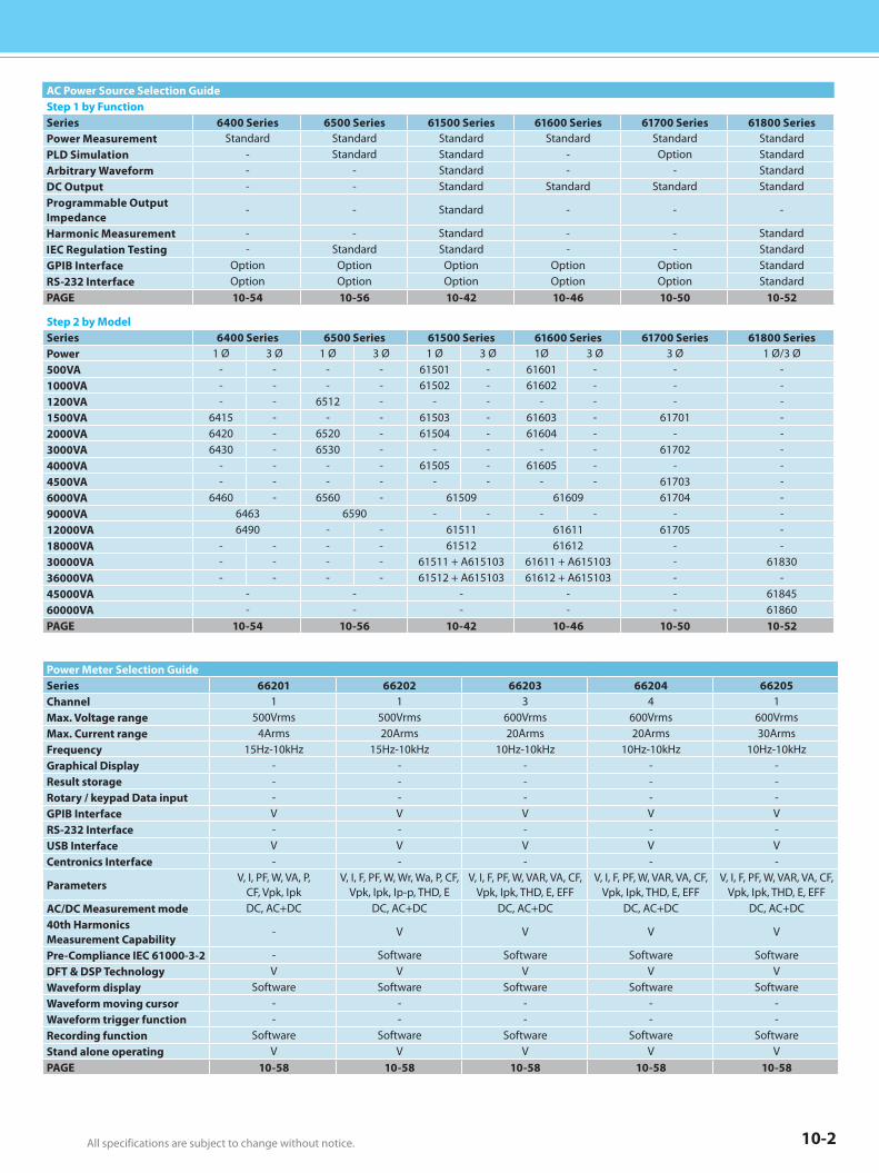
All specifications are subject to change without notice. All specifications are subject to change without notice. 10-2
Power Meter Selection GuideSeries 66201 66202 66203 66204 66205Channel 1 1 3 4 1Max. Voltage range 500Vrms 500Vrms 600Vrms 600Vrms 600VrmsMax. Current range 4Arms 20Arms 20Arms 20Arms 30ArmsFrequency 15Hz-10kHz 15Hz-10kHz 10Hz-10kHz 10Hz-10kHz 10Hz-10kHzGraphical Display - - - - -Result storage - - - - -Rotary / keypad Data input - - - - -GPIB Interface V V V V VRS-232 Interface - - - - -USB Interface V V V V VCentronics Interface - - - - -
ParametersV, I, PF, W, VA, P,
CF, Vpk, IpkV, I, F, PF, W, Wr, Wa, P, CF,
Vpk, Ipk, Ip-p, THD, EV, I, F, PF, W, VAR, VA, CF,
Vpk, Ipk, THD, E, EFFV, I, F, PF, W, VAR, VA, CF,
Vpk, Ipk, THD, E, EFFV, I, F, PF, W, VAR, VA, CF,
Vpk, Ipk, THD, E, EFFAC/DC Measurement mode DC, AC+DC DC, AC+DC DC, AC+DC DC, AC+DC DC, AC+DC40th HarmonicsMeasurement Capability
- V V V V
Pre-Compliance IEC 61000-3-2 - Software Software Software SoftwareDFT & DSP Technology V V V V VWaveform display Software Software Software Software SoftwareWaveform moving cursor - - - - -Waveform trigger function - - - - -Recording function Software Software Software Software SoftwareStand alone operating V V V V VPAGE 10-58 10-58 10-58 10-58 10-58
AC Power Source Selection GuideStep 1 by FunctionSeries 6400 Series 6500 Series 61500 Series 61600 Series 61700 Series 61800 SeriesPower Measurement Standard Standard Standard Standard Standard StandardPLD Simulation - Standard Standard - Option StandardArbitrary Waveform - - Standard - - StandardDC Output - - Standard Standard Standard StandardProgrammable Output Impedance
- - Standard - - -
Harmonic Measurement - - Standard - - StandardIEC Regulation Testing - Standard Standard - - StandardGPIB Interface Option Option Option Option Option StandardRS-232 Interface Option Option Option Option Option StandardPAGE 10-54 10-56 10-42 10-46 10-50 10-52
Step 2 by ModelSeries 6400 Series 6500 Series 61500 Series 61600 Series 61700 Series 61800 SeriesPower 1 Ø 3 Ø 1 Ø 3 Ø 1 Ø 3 Ø 1Ø 3 Ø 3 Ø 1 Ø/3 Ø500VA - - - - 61501 - 61601 - - -1000VA - - - - 61502 - 61602 - - -1200VA - - 6512 - - - - - - -1500VA 6415 - - - 61503 - 61603 - 61701 -2000VA 6420 - 6520 - 61504 - 61604 - - -3000VA 6430 - 6530 - - - - - 61702 -4000VA - - - - 61505 - 61605 - - -4500VA - - - - - - - - 61703 -6000VA 6460 - 6560 - 61509 61609 61704 -9000VA 6463 6590 - - - - - -12000VA 6490 - - 61511 61611 61705 -18000VA - - - - 61512 61612 - -30000VA - - - - 61511 + A615103 61611 + A615103 - 6183036000VA - - - - 61512 + A615103 61612 + A615103 - -45000VA - - - - - 6184560000VA - - - - - 61860PAGE 10-54 10-56 10-42 10-46 10-50 10-52
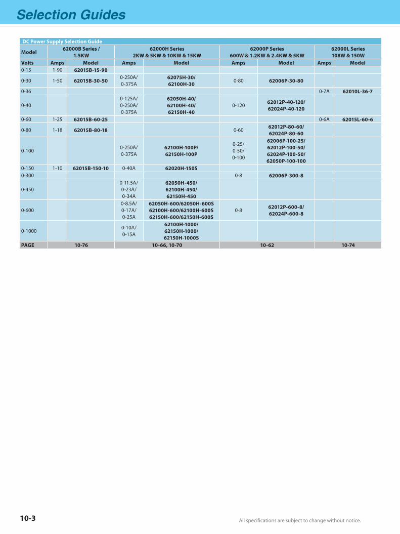
Selection Guides
All specifications are subject to change without notice. All specifications are subject to change without notice.10-3
DC Power Supply Selection Guide
Model62000B Series /
1.5KW62000H Series
2KW & 5KW & 10KW & 15KW62000P Series
600W & 1.2KW & 2.4KW & 5KW62000L Series108W & 150W
Volts Amps Model Amps Model Amps Model Amps Model0-15 1-90 62015B-15-90
0-30 1-50 62015B-30-500-250A/0-375A
62075H-30/62100H-30
0-80 62006P-30-80
0-36 0-7A 62010L-36-7
0-400-125A/0-250A/0-375A
62050H-40/62100H-40/62150H-40
0-120 62012P-40-120/62024P-40-120
0-60 1-25 62015B-60-25 0-6A 62015L-60-6
0-80 1-18 62015B-80-18 0-60 62012P-80-60/62024P-80-60
0-1000-250A/0-375A
62100H-100P/62150H-100P
0-25/0-50/0-100
62006P-100-25/62012P-100-50/62024P-100-50/62050P-100-100
0-150 1-10 62015B-150-10 0-40A 62020H-150S0-300 0-8 62006P-300-8
0-4500-11.5A/0-23A/0-34A
62050H-450/62100H-450/62150H-450
0-6000-8.5A/0-17A/0-25A
62050H-600/62050H-600S62100H-600/62100H-600S62150H-600/62150H-600S
0-8 62012P-600-8/62024P-600-8
0-10000-10A/0-15A
62100H-1000/62150H-1000/62150H-1000S
PAGE 10-76 10-66, 10-70 10-62 10-74
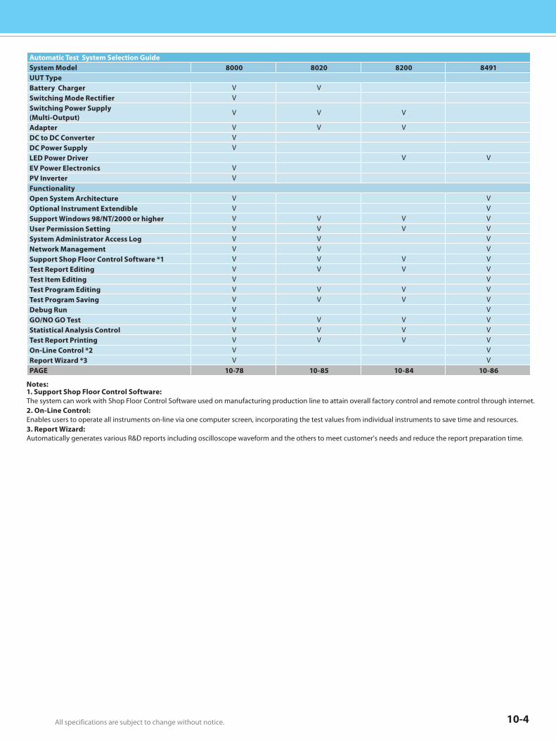
All specifications are subject to change without notice. All specifications are subject to change without notice. 10-4
Automatic Test System Selection GuideSystem Model 8000 8020 8200 8491UUT Type Battery Charger V VSwitching Mode Rectifier VSwitching Power Supply (Multi-Output)
V V V
Adapter V V VDC to DC Converter VDC Power Supply VLED Power Driver V VEV Power Electronics VPV Inverter VFunctionality Open System Architecture V VOptional Instrument Extendible V VSupport Windows 98/NT/2000 or higher V V V VUser Permission Setting V V V VSystem Administrator Access Log V V VNetwork Management V V VSupport Shop Floor Control Software *1 V V V VTest Report Editing V V V VTest Item Editing V VTest Program Editing V V V VTest Program Saving V V V VDebug Run V VGO/NO GO Test V V V VStatistical Analysis Control V V V VTest Report Printing V V V VOn-Line Control *2 V VReport Wizard *3 V VPAGE 10-78 10-85 10-84 10-86
Notes:1. Support Shop Floor Control Software: The system can work with Shop Floor Control Software used on manufacturing production line to attain overall factory control and remote control through internet.2. On-Line Control: Enables users to operate all instruments on-line via one computer screen, incorporating the test values from individual instruments to save time and resources.3. Report Wizard: Automatically generates various R&D reports including oscilloscope waveform and the others to meet customer's needs and reduce the report preparation time.
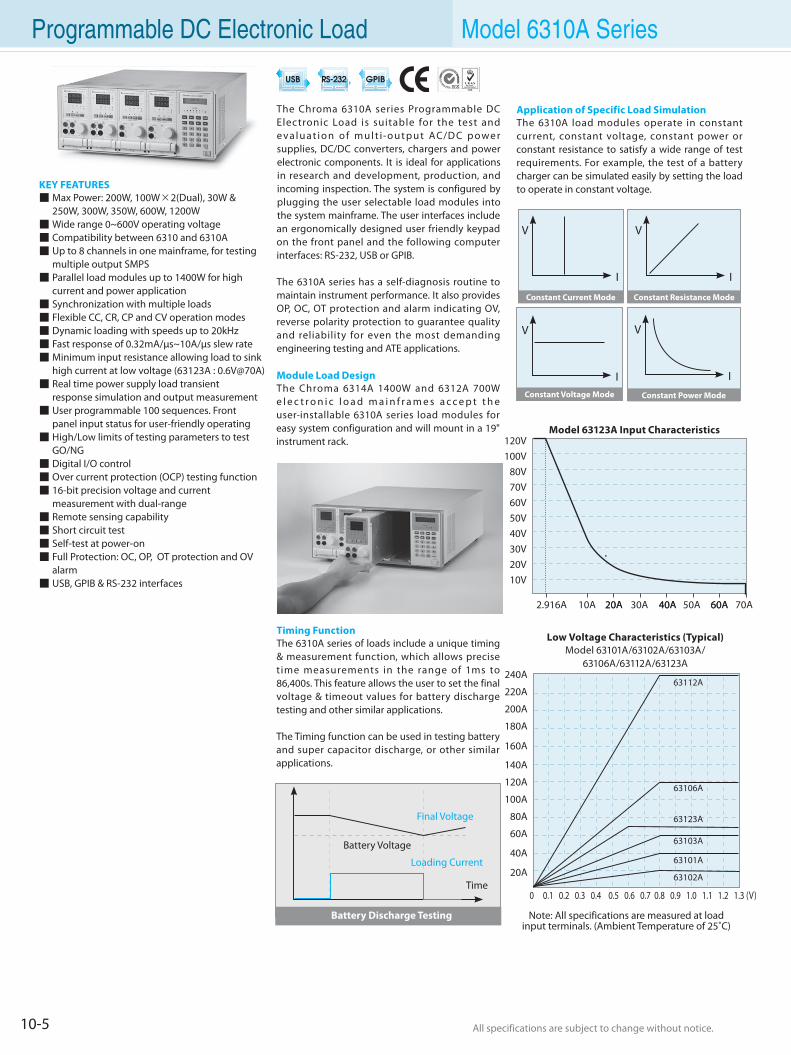
10-5 All specifications are subject to change without notice. All specifications are subject to change without notice.
Programmable DC Electronic Load Model 6310A Series
The Chroma 6310A series Programmable DC Electronic Load is suitable for the test and e va l u at i o n o f m u l t i-o u t p u t AC/D C p owe r supplies, DC/DC converters, chargers and power electronic components. It is ideal for applications in research and development, production, and incoming inspection. The system is configured by plugging the user selectable load modules into the system mainframe. The user interfaces include an ergonomically designed user friendly keypad on the front panel and the following computer interfaces: RS-232, USB or GPIB.
The 6310A series has a self-diagnosis routine to maintain instrument performance. It also provides OP, OC, OT protection and alarm indicating OV, reverse polarity protection to guarantee quality and reliability for even the most demanding engineering testing and ATE applications.
Module Load DesignThe Chroma 6314A 1400W and 6312A 700W e l e c t r o n i c l o a d m a i n f r a m e s a c c e p t t h e user-installable 6310A series load modules for easy system configuration and will mount in a 19" instrument rack.
Timing FunctionThe 6310A series of loads include a unique timing & measurement function, which allows precise time measurements in the range of 1ms to 86,400s. This feature allows the user to set the final voltage & timeout values for battery discharge testing and other similar applications.
The Timing function can be used in testing battery and super capacitor discharge, or other similar applications.
KEY FEATURES Max Power: 200W, 100W×2(Dual), 30W & 250W, 300W, 350W, 600W, 1200W Wide range 0~600V operating voltage Compatibility between 6310 and 6310A Up to 8 channels in one mainframe, for testing multiple output SMPS Parallel load modules up to 1400W for high current and power application Synchronization with multiple loads Flexible CC, CR, CP and CV operation modes Dynamic loading with speeds up to 20kHz Fast response of 0.32mA/µs~10A/µs slew rate Minimum input resistance allowing load to sink high current at low voltage (63123A : 0.6V@70A) Real time power supply load transient response simulation and output measurement User programmable 100 sequences. Front panel input status for user-friendly operating High/Low limits of testing parameters to test GO/NG Digital I/O control Over current protection (OCP) testing function 16-bit precision voltage and current measurement with dual-range Remote sensing capability Short circuit test Self-test at power-on Full Protection: OC, OP, OT protection and OV alarm USB, GPIB & RS-232 interfaces
Final Voltage
Time
Battery Discharge Testing
Battery Voltage
Loading Current
Constant Current Mode Constant Resistance Mode
Constant Voltage Mode Constant Power Mode
V
I
V
I
V
I
V
I
Model 63123A Input Characteristics
Low Voltage Characteristics (Typical)Model 63101A/63102A/63103A/
63106A/63112A/63123A240A
220A
200A
180A
160A
140A
120A
100A
80A
60A
40A
0 0.1 0.2 0.3 0.4 0.5 0.6 0.7 0.8 0.9 1.0 1.1 1.2 1.3 (V)
63112A
63106A
63103A
63101A
63102A
Note: All specifications are measured at loadinput terminals. (Ambient Temperature of 25˚C)
20A
Application of Specific Load SimulationThe 6310A load modules operate in constant current, constant voltage, constant power or constant resistance to satisfy a wide range of test requirements. For example, the test of a battery charger can be simulated easily by setting the load to operate in constant voltage.
63123A
80V100V120V
70V60V50V40V30V20V10V
2.916A 10A 20A 40A 60A30A 50A 70A20A 40A 60A
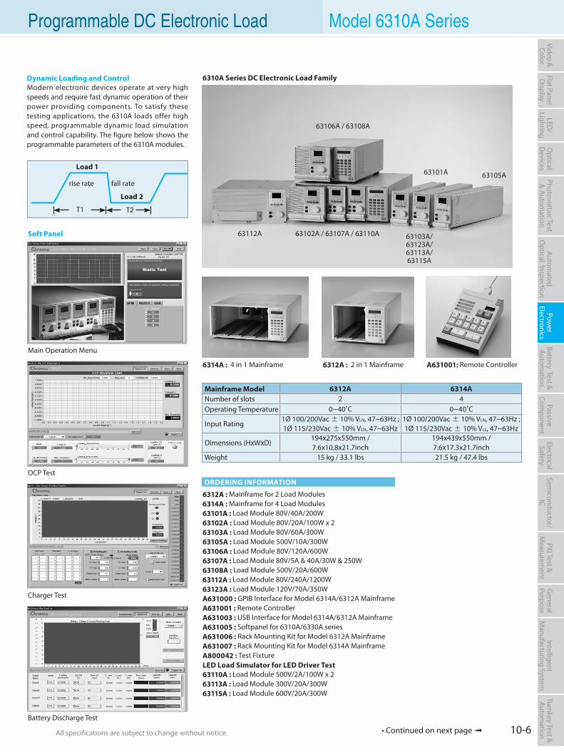
10-6All specifications are subject to change without notice. All specifications are subject to change without notice.
Flat PanelD
isplayPow
er Electronics
Electrical Safety
General
PurposePassive
Component
Semiconductor/
ICBattery Test & Autom
ationAutom
atedO
ptical Inspection Photovoltaic Test
& Automation
PXI Test &
Measurem
ent Video & Color
LED/
LightingO
ptical D
evicesIntelligent
Manufacturing System
Turnkey Test & Autom
ation Programmable DC Electronic Load Model 6310A Series
Load 1
Load 2
T1 T2
rise rate fall rate
Mainframe Model 6312A 6314ANumber of slots 2 4Operating Temperature 0~40˚C 0~40˚C
Input Rating1Ø 100/200Vac ± 10% VLN, 47~63Hz ; 1Ø 115/230Vac ± 10% VLN, 47~63Hz
1Ø 100/200Vac ± 10% VLN, 47~63Hz ; 1Ø 115/230Vac ± 10% VLL, 47~63Hz
Dimensions (HxWxD)194x275x550mm / 7.6x10.8x21.7inch
194x439x550mm / 7.6x17.3x21.7inch
Weight 15 kg / 33.1 lbs 21.5 kg / 47.4 lbs
ORDERING INFORMATION
6312A : Mainframe for 2 Load Modules6314A : Mainframe for 4 Load Modules63101A : Load Module 80V/40A/200W63102A : Load Module 80V/20A/100W x 263103A : Load Module 80V/60A/300W63105A : Load Module 500V/10A/300W63106A : Load Module 80V/120A/600W63107A : Load Module 80V/5A & 40A/30W & 250W63108A : Load Module 500V/20A/600W63112A : Load Module 80V/240A/1200W63123A : Load Module 120V/70A/350WA631000 : GPIB Interface for Model 6314A/6312A MainframeA631001 : Remote ControllerA631003 : USB Interface for Model 6314A/6312A MainframeA631005 : Softpanel for 6310A/6330A seriesA631006 : Rack Mounting Kit for Model 6312A MainframeA631007 : Rack Mounting Kit for Model 6314A MainframeA800042 : Test FixtureLED Load Simulator for LED Driver Test63110A : Load Module 500V/2A/100W x 263113A : Load Module 300V/20A/300W63115A : Load Module 600V/20A/300W
6310A Series DC Electronic Load Family
6312A : 2 in 1 Mainframe6314A : 4 in 1 Mainframe
63106A / 63108A
63102A / 63107A / 63110A
63101A 63105A
63112A 63103A/63123A/ 63113A/63115A
A631001: Remote Controller
• Continued on next page
Dynamic Loading and ControlModern electronic devices operate at very high speeds and require fast dynamic operation of their power providing components. To satisfy these testing applications, the 6310A loads offer high speed, programmable dynamic load simulation and control capability. The figure below shows the programmable parameters of the 6310A modules.
Main Operation Menu
OCP Test
Charger Test
Battery Discharge Test
Soft Panel
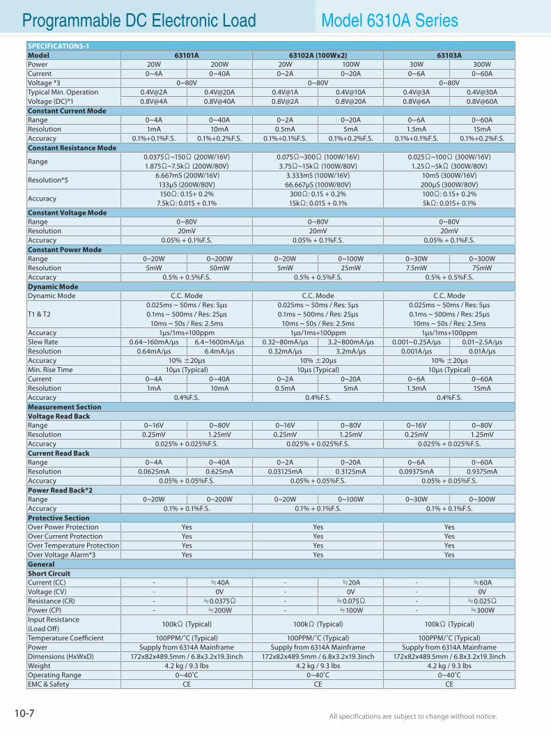
10-7 All specifications are subject to change without notice. All specifications are subject to change without notice.
Programmable DC Electronic Load Model 6310A SeriesSPECIFICATIONS-1Model 63101A 63102A (100Wx2) 63103APower 20W 200W 20W 100W 30W 300WCurrent 0~4A 0~40A 0~2A 0~20A 0~6A 0~60AVoltage *3 0~80V 0~80V 0~80VTypical Min. Operation Voltage (DC)*1
0.4V@2A 0.4V@20A 0.4V@1A 0.4V@10A 0.4V@3A [email protected]@4A 0.8V@40A 0.8V@2A 0.8V@20A 0.8V@6A 0.8V@60A
Constant Current ModeRange 0~4A 0~40A 0~2A 0~20A 0~6A 0~60AResolution 1mA 10mA 0.5mA 5mA 1.5mA 15mAAccuracy 0.1%+0.1%F.S. 0.1%+0.2%F.S. 0.1%+0.1%F.S. 0.1%+0.2%F.S. 0.1%+0.1%F.S. 0.1%+0.2%F.S.Constant Resistance Mode
Range0.0375Ω~150Ω (200W/16V)1.875Ω~7.5kΩ (200W/80V)
0.075Ω~300Ω (100W/16V)3.75Ω~15kΩ (100W/80V)
0.025Ω~100Ω (300W/16V)1.25Ω~5kΩ (300W/80V)
Resolution*5 6.667mS (200W/16V)
133µS (200W/80V)3.333mS (100W/16V)66.667µS (100W/80V)
10mS (300W/16V)200µS (300W/80V)
Accuracy150Ω: 0.1S+ 0.2%
7.5kΩ: 0.01S + 0.1% 300Ω: 0.1S + 0.2%15kΩ: 0.01S + 0.1%
100Ω: 0.1S+ 0.2%5kΩ: 0.01S+ 0.1%
Constant Voltage ModeRange 0~80V 0~80V 0~80VResolution 20mV 20mV 20mVAccuracy 0.05% + 0.1%F.S. 0.05% + 0.1%F.S. 0.05% + 0.1%F.S.Constant Power ModeRange 0~20W 0~200W 0~20W 0~100W 0~30W 0~300WResolution 5mW 50mW 5mW 25mW 7.5mW 75mWAccuracy 0.5% + 0.5%F.S. 0.5% + 0.5%F.S. 0.5% + 0.5%F.S.Dynamic ModeDynamic Mode C.C. Mode C.C. Mode C.C. Mode
T1 & T20.025ms ~ 50ms / Res: 5µs0.1ms ~ 500ms / Res: 25µs
10ms ~ 50s / Res: 2.5ms
0.025ms ~ 50ms / Res: 5µs0.1ms ~ 500ms / Res: 25µs
10ms ~ 50s / Res: 2.5ms
0.025ms ~ 50ms / Res: 5µs0.1ms ~ 500ms / Res: 25µs
10ms ~ 50s / Res: 2.5msAccuracy 1µs/1ms+100ppm 1µs/1ms+100ppm 1µs/1ms+100ppmSlew Rate 0.64~160mA/µs 6.4~1600mA/µs 0.32~80mA/µs 3.2~800mA/µs 0.001~0.25A/µs 0.01~2.5A/µsResolution 0.64mA/µs 6.4mA/µs 0.32mA/µs 3.2mA/µs 0.001A/µs 0.01A/µsAccuracy 10% ±20µs 10% ±20µs 10% ±20µsMin. Rise Time 10µs (Typical) 10µs (Typical) 10µs (Typical)Current 0~4A 0~40A 0~2A 0~20A 0~6A 0~60AResolution 1mA 10mA 0.5mA 5mA 1.5mA 15mAAccuracy 0.4%F.S. 0.4%F.S. 0.4%F.S.Measurement SectionVoltage Read Back Range 0~16V 0~80V 0~16V 0~80V 0~16V 0~80VResolution 0.25mV 1.25mV 0.25mV 1.25mV 0.25mV 1.25mVAccuracy 0.025% + 0.025%F.S. 0.025% + 0.025%F.S. 0.025% + 0.025%F.S.Current Read BackRange 0~4A 0~40A 0~2A 0~20A 0~6A 0~60AResolution 0.0625mA 0.625mA 0.03125mA 0.3125mA 0.09375mA 0.9375mAAccuracy 0.05% + 0.05%F.S. 0.05% + 0.05%F.S. 0.05% + 0.05%F.S.Power Read Back*2Range 0~20W 0~200W 0~20W 0~100W 0~30W 0~300WAccuracy 0.1% + 0.1%F.S. 0.1% + 0.1%F.S. 0.1% + 0.1%F.S.Protective SectionOver Power Protection Yes Yes YesOver Current Protection Yes Yes YesOver Temperature Protection Yes Yes YesOver Voltage Alarm*3 Yes Yes YesGeneralShort CircuitCurrent (CC) - ≒40A - ≒20A - ≒60AVoltage (CV) - 0V - 0V - 0VResistance (CR) - ≒0.0375Ω - ≒0.075Ω - ≒0.025ΩPower (CP) - ≒200W - ≒100W - ≒300WInput Resistance(Load Off)
100kΩ (Typical) 100kΩ (Typical) 100kΩ (Typical)
Temperature Coefficient 100PPM/˚C (Typical) 100PPM/˚C (Typical) 100PPM/˚C (Typical)Power Supply from 6314A Mainframe Supply from 6314A Mainframe Supply from 6314A MainframeDimensions (HxWxD) 172x82x489.5mm / 6.8x3.2x19.3inch 172x82x489.5mm / 6.8x3.2x19.3inch 172x82x489.5mm / 6.8x3.2x19.3inchWeight 4.2 kg / 9.3 lbs 4.2 kg / 9.3 lbs 4.2 kg / 9.3 lbsOperating Range 0~40˚C 0~40˚C 0~40˚CEMC & Safety CE CE CE
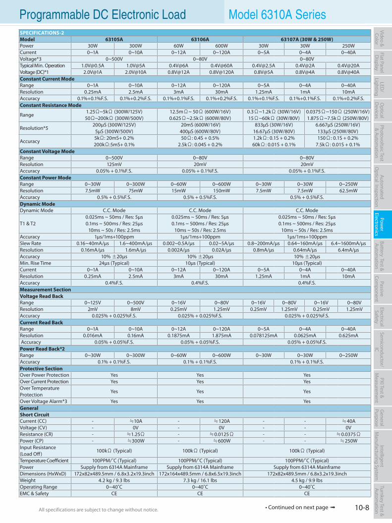
10-8All specifications are subject to change without notice. All specifications are subject to change without notice.
Flat PanelD
isplayPow
er Electronics
Electrical Safety
General
PurposePassive
Component
Semiconductor/
ICBattery Test & Autom
ationAutom
atedO
ptical Inspection Photovoltaic Test
& Automation
PXI Test &
Measurem
ent Video & Color
LED/
LightingO
ptical D
evicesIntelligent
Manufacturing System
Turnkey Test & Autom
ation Programmable DC Electronic Load Model 6310A SeriesSPECIFICATIONS-2Model 63105A 63106A 63107A (30W & 250W)Power 30W 300W 60W 600W 30W 30W 250WCurrent 0~1A 0~10A 0~12A 0~120A 0~5A 0~4A 0~40AVoltage*3 0~500V 0~80V 0~80VTypical Min. Operation Voltage (DC)*1
[email protected] 1.0V@5A 0.4V@6A 0.4V@60A [email protected] 0.4V@2A [email protected]@1A 2.0V@10A 0.8V@12A 0.8V@120A 0.8V@5A 0.8V@4A 0.8V@40A
Constant Current ModeRange 0~1A 0~10A 0~12A 0~120A 0~5A 0~4A 0~40AResolution 0.25mA 2.5mA 3mA 30mA 1.25mA 1mA 10mAAccuracy 0.1%+0.1%F.S. 0.1%+0.2%F.S. 0.1%+0.1%F.S. 0.1%+0.2%F.S. 0.1%+0.1%F.S. 0.1%+0.1%F.S. 0.1%+0.2%F.S.Constant Resistance Mode
Range1.25Ω~5kΩ (300W/125V)50Ω~200kΩ (300W/500V)
12.5mΩ~ 50Ω (600W/16V)0.625Ω~2.5kΩ (600W/80V)
0.3Ω~1.2kΩ (30W/16V)15Ω~60kΩ (30W/80V)
0.0375Ω~150Ω (250W/16V)1.875Ω~7.5kΩ (250W/80V)
Resolution*5200µS (300W/125V)
5µS (300W/500V) 20mS (600W/16V)400µS (600W/80V)
833µS (30W/16V)16.67µS (30W/80V)
6.667µS (250W/16V)133µS (250W/80V)
Accuracy5kΩ: 20mS+ 0.2%200kΩ:5mS+ 0.1%
50Ω: 0.4S + 0.5%2.5kΩ: 0.04S + 0.2%
1.2kΩ: 0.1S + 0.2%60kΩ: 0.01S + 0.1%
150Ω: 0.1S + 0.2%7.5kΩ: 0.01S + 0.1%
Constant Voltage ModeRange 0~500V 0~80V 0~80VResolution 125mV 20mV 20mVAccuracy 0.05% + 0.1%F.S. 0.05% + 0.1%F.S. 0.05% + 0.1%F.S.Constant Power ModeRange 0~30W 0~300W 0~60W 0~600W 0~30W 0~30W 0~250WResolution 7.5mW 75mW 15mW 150mW 7.5mW 7.5mW 62.5mWAccuracy 0.5% + 0.5%F.S. 0.5% + 0.5%F.S. 0.5% + 0.5%F.S.Dynamic ModeDynamic Mode C.C. Mode C.C. Mode C.C. Mode
T1 & T20.025ms ~ 50ms / Res: 5µs0.1ms ~ 500ms / Res: 25µs
10ms ~ 50s / Res: 2.5ms
0.025ms ~ 50ms / Res: 5µs0.1ms ~ 500ms / Res: 25µs
10ms ~ 50s / Res: 2.5ms
0.025ms ~ 50ms / Res: 5µs0.1ms ~ 500ms / Res: 25µs
10ms ~ 50s / Res: 2.5msAccuracy 1µs/1ms+100ppm 1µs/1ms+100ppm 1µs/1ms+100ppmSlew Rate 0.16~40mA/µs 1.6~400mA/µs 0.002~0.5A/µs 0.02~5A/µs 0.8~200mA/µs 0.64~160mA/µs 6.4~1600mA/µsResolution 0.16mA/µs 1.6mA/µs 0.002A/µs 0.02A/µs 0.8mA/µs 0.64mA/µs 6.4mA/µsAccuracy 10% ±20µs 10% ±20µs 10% ±20µsMin. Rise Time 24µs (Typical) 10µs (Typical) 10µs (Typical)Current 0~1A 0~10A 0~12A 0~120A 0~5A 0~4A 0~40AResolution 0.25mA 2.5mA 3mA 30mA 1.25mA 1mA 10mAAccuracy 0.4%F.S. 0.4%F.S. 0.4%F.S.Measurement SectionVoltage Read Back Range 0~125V 0~500V 0~16V 0~80V 0~16V 0~80V 0~16V 0~80VResolution 2mV 8mV 0.25mV 1.25mV 0.25mV 1.25mV 0.25mV 1.25mVAccuracy 0.025% + 0.025%F.S. 0.025% + 0.025%F.S. 0.025% + 0.025%F.S.Current Read BackRange 0~1A 0~10A 0~12A 0~120A 0~5A 0~4A 0~40AResolution 0.016mA 0.16mA 0.1875mA 1.875mA 0.078125mA 0.0625mA 0.625mA Accuracy 0.05% + 0.05%F.S. 0.05% + 0.05%F.S. 0.05% + 0.05%F.S.Power Read Back*2Range 0~30W 0~300W 0~60W 0~600W 0~30W 0~30W 0~250WAccuracy 0.1% + 0.1%F.S. 0.1% + 0.1%F.S. 0.1% + 0.1%F.S.Protective SectionOver Power Protection Yes Yes YesOver Current Protection Yes Yes YesOver TemperatureProtection
Yes Yes Yes
Over Voltage Alarm*3 Yes Yes YesGeneralShort CircuitCurrent (CC) - ≒10A - ≒120A - - ≒40AVoltage (CV) - 0V - 0V - - 0VResistance (CR) - ≒1.25Ω - ≒0.0125Ω - - ≒0.0375ΩPower (CP) - ≒300W - ≒600W - - ≒250WInput Resistance(Load Off)
100kΩ (Typical) 100kΩ (Typical) 100kΩ (Typical)
Temperature Coefficient 100PPM/˚C (Typical) 100PPM/˚C (Typical) 100PPM/˚C (Typical)Power Supply from 6314A Mainframe Supply from 6314A Mainframe Supply from 6314A MainframeDimensions (HxWxD) 172x82x489.5mm / 6.8x3.2x19.3inch 172x164x489.5mm / 6.8x6.5x19.3inch 172x82x489.5mm / 6.8x3.2x19.3inchWeight 4.2 kg / 9.3 lbs 7.3 kg / 16.1 lbs 4.5 kg / 9.9 lbsOperating Range 0~40˚C 0~40˚C 0~40˚CEMC & Safety CE CE CE
• Continued on next page
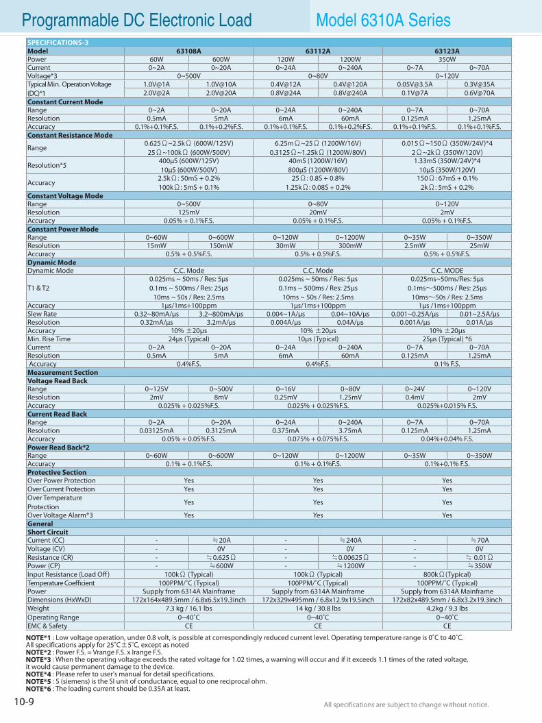
10-9 All specifications are subject to change without notice. All specifications are subject to change without notice.
Programmable DC Electronic Load Model 6310A SeriesSPECIFICATIONS-3Model 63108A 63112A 63123APower 60W 600W 120W 1200W 350WCurrent 0~2A 0~20A 0~24A 0~240A 0~7A 0~70AVoltage*3 0~500V 0~80V 0~120VTypical Min. Operation Voltage (DC)*1
1.0V@1A 1.0V@10A 0.4V@12A 0.4V@120A [email protected] [email protected]@2A 2.0V@20A 0.8V@24A 0.8V@240A 0.1V@7A 0.6V@70A
Constant Current ModeRange 0~2A 0~20A 0~24A 0~240A 0~7A 0~70AResolution 0.5mA 5mA 6mA 60mA 0.125mA 1.25mAAccuracy 0.1%+0.1%F.S. 0.1%+0.2%F.S. 0.1%+0.1%F.S. 0.1%+0.2%F.S. 0.1%+0.1%F.S. 0.1%+0.1%F.S.Constant Resistance Mode
Range0.625Ω~2.5kΩ (600W/125V)
25Ω~100kΩ (600W/500V) 6.25mΩ~25Ω (1200W/16V)
0.3125Ω~1.25kΩ (1200W/80V) 0.015Ω~150Ω (350W/24V)*4
2Ω~2kΩ (350W/120V)
Resolution*5400µS (600W/125V)10µS (600W/500V)
40mS (1200W/16V)800µS (1200W/80V)
1.33mS (350W/24V)*410µS (350W/120V)
Accuracy2.5kΩ: 50mS + 0.2%100kΩ: 5mS + 0.1%
25Ω: 0.8S + 0.8%1.25kΩ: 0.08S + 0.2%
150Ω: 67mS + 0.1%2kΩ: 5mS + 0.2%
Constant Voltage ModeRange 0~500V 0~80V 0~120VResolution 125mV 20mV 2mVAccuracy 0.05% + 0.1%F.S. 0.05% + 0.1%F.S. 0.05% + 0.1%F.S.Constant Power ModeRange 0~60W 0~600W 0~120W 0~1200W 0~35W 0~350WResolution 15mW 150mW 30mW 300mW 2.5mW 25mWAccuracy 0.5% + 0.5%F.S. 0.5% + 0.5%F.S. 0.5% + 0.5%F.S.Dynamic ModeDynamic Mode C.C. Mode C.C. Mode C.C. MODE
T1 & T20.025ms ~ 50ms / Res: 5µs0.1ms ~ 500ms / Res: 25µs
10ms ~ 50s / Res: 2.5ms
0.025ms ~ 50ms / Res: 5µs0.1ms ~ 500ms / Res: 25µs
10ms ~ 50s / Res: 2.5ms
0.025ms~50ms/Res: 5µs0.1ms∼500ms / Res: 25µs
10ms∼50s / Res: 2.5msAccuracy 1µs/1ms+100ppm 1µs/1ms+100ppm 1µs /1ms+100ppmSlew Rate 0.32~80mA/µs 3.2~800mA/µs 0.004~1A/µs 0.04~10A/µs 0.001~0.25A/µs 0.01~2.5A/µsResolution 0.32mA/µs 3.2mA/µs 0.004A/µs 0.04A/µs 0.001A/µs 0.01A/µsAccuracy 10% ±20µs 10% ±20µs 10% ±20µsMin. Rise Time 24µs (Typical) 10µs (Typical) 25µs (Typical) *6Current 0~2A 0~20A 0~24A 0~240A 0~7A 0~70AResolution 0.5mA 5mA 6mA 60mA 0.125mA 1.25mA Accuracy 0.4%F.S. 0.4%F.S. 0.1% F.S.Measurement SectionVoltage Read Back Range 0~125V 0~500V 0~16V 0~80V 0~24V 0~120VResolution 2mV 8mV 0.25mV 1.25mV 0.4mV 2mVAccuracy 0.025% + 0.025%F.S. 0.025% + 0.025%F.S. 0.025%+0.015% F.S.Current Read BackRange 0~2A 0~20A 0~24A 0~240A 0~7A 0~70AResolution 0.03125mA 0.3125mA 0.375mA 3.75mA 0.125mA 1.25mAAccuracy 0.05% + 0.05%F.S. 0.075% + 0.075%F.S. 0.04%+0.04% F.S.Power Read Back*2Range 0~60W 0~600W 0~120W 0~1200W 0~35W 0~350WAccuracy 0.1% + 0.1%F.S. 0.1% + 0.1%F.S. 0.1%+0.1% F.S.Protective SectionOver Power Protection Yes Yes YesOver Current Protection Yes Yes YesOver TemperatureProtection
Yes Yes Yes
Over Voltage Alarm*3 Yes Yes YesGeneralShort CircuitCurrent (CC) - ≒20A - ≒240A - ≒70AVoltage (CV) - 0V - 0V - 0VResistance (CR) - ≒0.625Ω - ≒0.00625Ω - ≒ 0.01ΩPower (CP) - ≒600W - ≒1200W - ≒350WInput Resistance (Load Off) 100kΩ (Typical) 100kΩ (Typical) 800kΩ(Typical)Temperature Coefficient 100PPM/˚C (Typical) 100PPM/˚C (Typical) 100PPM/˚C (Typical)Power Supply from 6314A Mainframe Supply from 6314A Mainframe Supply from 6314A MainframeDimensions (HxWxD) 172x164x489.5mm / 6.8x6.5x19.3inch 172x329x495mm / 6.8x12.9x19.5inch 172x82x489.5mm / 6.8x3.2x19.3inchWeight 7.3 kg / 16.1 lbs 14 kg / 30.8 lbs 4.2kg / 9.3 lbsOperating Range 0~40˚C 0~40˚C 0~40˚CEMC & Safety CE CE CE
NOTE*1 : Low voltage operation, under 0.8 volt, is possible at correspondingly reduced current level. Operating temperature range is 0˚C to 40˚C. All specifications apply for 25˚C±5˚C, except as notedNOTE*2 : Power F.S. = Vrange F.S. x Irange F.S.NOTE*3 : When the operating voltage exceeds the rated voltage for 1.02 times, a warning will occur and if it exceeds 1.1 times of the rated voltage, it would cause permanent damage to the device.NOTE*4 : Please refer to user's manual for detail specifications.NOTE*5 : S (siemens) is the SI unit of conductance, equal to one reciprocal ohm.NOTE*6 : The loading current should be 0.35A at least.
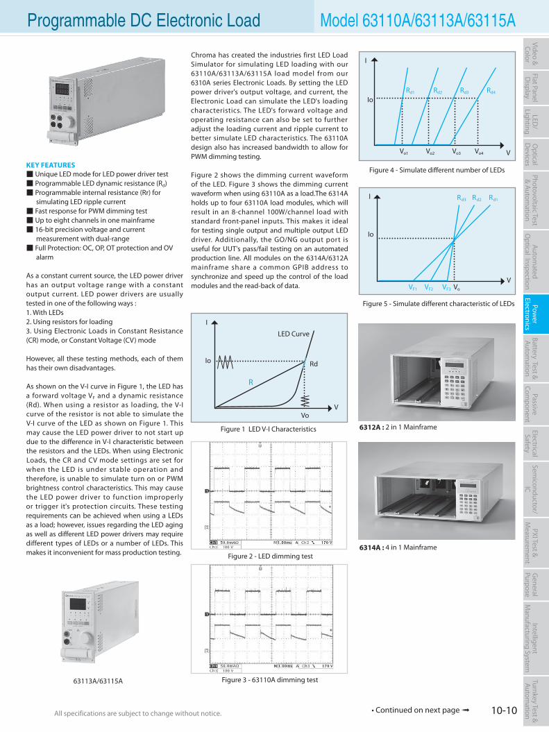
10-10All specifications are subject to change without notice. All specifications are subject to change without notice.
Flat PanelD
isplayPow
er Electronics
Electrical Safety
General
PurposePassive
Component
Semiconductor/
ICBattery Test & Autom
ationAutom
atedO
ptical Inspection Photovoltaic Test
& Automation
PXI Test &
Measurem
ent Video & Color
LED/
LightingO
ptical D
evicesIntelligent
Manufacturing System
Turnkey Test & Autom
ation Programmable DC Electronic Load Model 63110A/63113A/63115A
• Continued on next page
KEY FEATURES Unique LED mode for LED power driver test Programmable LED dynamic resistance (Rd) Programmable internal resistance (Rr) for simulating LED ripple current Fast response for PWM dimming test Up to eight channels in one mainframe 16-bit precision voltage and current measurement with dual-range Full Protection: OC, OP, OT protection and OV alarm
As a constant current source, the LED power driver has an output voltage range with a constant output current. LED power drivers are usually tested in one of the following ways :1. With LEDs 2. Using resistors for loading 3. Using Electronic Loads in Constant Resistance (CR) mode, or Constant Voltage (CV) mode
However, all these testing methods, each of them has their own disadvantages.
As shown on the V-I curve in Figure 1, the LED has a forward voltage VF and a dynamic resistance (Rd). When using a resistor as loading, the V-I curve of the resistor is not able to simulate the V-I curve of the LED as shown on Figure 1. This may cause the LED power driver to not start up due to the difference in V-I characteristic between the resistors and the LEDs. When using Electronic Loads, the CR and CV mode settings are set for when the LED is under stable operation and therefore, is unable to simulate turn on or PWM brightness control characteristics. This may cause the LED power driver to function improperly or trigger it's protection circuits. These testing requirements can be achieved when using a LEDs as a load; however, issues regarding the LED aging as well as different LED power drivers may require different types of LEDs or a number of LEDs. This makes it inconvenient for mass production testing.
Figure 3 - 63110A dimming test
I
Figure 5 - Simulate different characteristic of LEDs
VVF1 VF2 VF3 Vo
Io
Rd3 Rd2 Rd1
I
Io
Vo1 Vo2 Vo3 Vo4
Figure 4 - Simulate different number of LEDs
63113A/63115A
Rd1 Rd2 Rd3 Rd4
Figure 2 - LED dimming test
6312A : 2 in 1 Mainframe
6314A : 4 in 1 Mainframe
Chroma has created the industries first LED Load Simulator for simulating LED loading with our 63110A/63113A/63115A load model from our 6310A series Electronic Loads. By setting the LED power driver's output voltage, and current, the Electronic Load can simulate the LED's loading characteristics. The LED's forward voltage and operating resistance can also be set to further adjust the loading current and ripple current to better simulate LED characteristics. The 63110A design also has increased bandwidth to allow for PWM dimming testing.
Figure 2 shows the dimming current waveform of the LED. Figure 3 shows the dimming current waveform when using 63110A as a load.The 6314A holds up to four 63110A load modules, which will result in an 8-channel 100W/channel load with standard front-panel inputs. This makes it ideal for testing single output and multiple output LED driver. Additionally, the GO/NG output port is useful for UUT's pass/fail testing on an automated production line. All modules on the 6314A/6312A mainframe share a common GPIB address to synchronize and speed up the control of the load modules and the read-back of data.
I
V
LED Curve
Vo
Io Rd
Figure 1 LED V-I Characteristics
V
I
I
Io
R
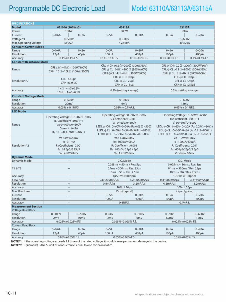
10-11 All specifications are subject to change without notice. All specifications are subject to change without notice.
Programmable DC Electronic Load Model 63110A/63113A/63115A
SPECIFICATIONSModel 63110A (100Wx2) 63113A 63115APower 100W 300W 300WCurrent 0~0.6A 0~2A 0~5A 0~20A 0~5A 0~20AVoltage *1 0~500V 0~300V 0~600VMin. Operating Voltage 6V@2A 4V@20A 4V@20AConstant Current Mode Range 0~0.6A 0~2A 0~5A 0~20A 0~5A 0~20AResolution 12µA 40µA 100µA 400µA 100µA 400µAAccuracy 0.1%+0.1% F.S. 0.1%+0.1% F.S. 0.1%+0.2% F.S. 0.1%+0.1% F.S. 0.1%+0.2% F.S.Constant Resistance Mode
RangeCRL : 3Ω~1kΩ (100W/100V)
CRH : 10Ω~10kΩ (100W/500V)
CRL @ CH : 0.2Ω~200Ω (300W/60V)CRL @ CL : 0.8Ω~800Ω (300W/60V)CRH @ CL : 4Ω~4kΩ (300W/300V)
CRL @ CH : 0.2Ω~200Ω (300W/60V)CRL @ CL : 0.8Ω~800Ω (300W/60V)CRH @ CL : 8Ω~8kΩ (300W/600V)
Resolution*2CRL : 62.5µSCRH : 6.25µS
CRL @ CH : 100µSCRL @ CL : 25µSCRH @ CL : 5µS
CRL @ CH :100µSCRL @ CL : 25µSCRH @ CL : 2.5µS
Accuracy1kΩ : 4mS+0.2%
10kΩ : 1mS+0.1%0.2% (setting + range) 0.2% (setting + range)
Constant Voltage Mode Range 0~500V 0~300V 0~600VResolution 20mV 6mV 12mVAccuracy 0.05% + 0.1%F.S. 0.05% + 0.1%F.S. 0.05% + 0.1%F.S.LED Mode
Range
Operating Voltage: 0~100V/0~500V Rd Coefficient : 0.001~1
VF: 0~100V/0~500VCurrent : 0~2A
Rd: 1Ω~1kΩ/10Ω~10kΩ
Operating Voltage : 0~60V/0~300VRd Coefficient : 0.001~1
VF : 0~60V/0~300VLEDL @ CH : 0~60V- 0~20A (Rd: 0.05Ω~50Ω)LEDL @ CL : 0~60V- 0~5A (Rd: 0.8Ω~800Ω)LEDH @ CL : 0~300V- 0~5A (Rd: 4Ω~4kΩ)
Operating Voltage : 0~60V/0~600VRd Coefficient : 0.001~1
VF : 0~60V/0~600VLEDL @ CH : 0~60V- 0~20A (Rd: 0.05Ω~50Ω)LEDL @ CL : 0~60V- 0~5A (Rd: 0.8Ω~800Ω)LEDH @ CL : 0~600V- 0~5A (Rd: 8Ω~8kΩ)
Resolution *2
Vo : 4mV/20mVIo : 0.1mA
Rd Coefficient : 0.001Rd : 62.5µS/6.25µS
VF : 4mV/20mV
Vo : 1.2mV/6mVIo : 100µA/400µA
Rd Coefficient : 0.001Rd : 400µS / 25µS / 5µS
VF : 1.2mV/ 6mV
Vo : 1.2mV/12mVIo : 100µA/400µA
Rd Coefficient : 0.001Rd : 400µS/25µS/2.5µS
VF : 6mV/ 60mVDynamic ModeDynamic Mode -- C.C. Mode C.C. Mode
T1 & T2 --0.025ms ~ 50ms / Res: 5µs0.1ms ~ 500ms / Res: 25µs
10ms ~ 50s / Res: 2.5ms
0.025ms ~ 50ms / Res: 5µs0.1ms ~ 500ms / Res: 25µs
10ms ~ 50s / Res: 2.5msAccuracy -- 1µs/1ms+100ppm 1µs/1ms+100ppmSlew Rate -- 0.8~200mA/µs 3.2~800mA/µs 0.8~200mA/µs 3.2~800mA/µsResolution -- 0.8mA/µs 3.2mA/µs 0.8mA/µs 3.2mA/µsAccuracy -- 10% ±20µs 10% ±20µsMin. Rise Time -- 25µs (Typical) 25µs (Typical)Current -- 0~5A 0~20A 0~5A 0~20AResolution -- 100µA 400µA 100µA 400µAAccuracy -- 0.4%F.S. 0.4%F.S.Measurement SectionVoltage Read BackRange 0~100V 0~500V 0~60V 0~300V 0~60V 0~600VResolution 2mV 10mV 1.2mV 6mV 1.2mV 12mVAccuracy 0.025%+0.025% F.S. 0.025%+0.025% F.S. 0.025%+0.025% F.S.Current Read BackRange 0~0.6A 0~2A 0~5A 0~20A 0~5A 0~20AResolution 12µA 40µA 100µA 400µA 100µA 400µAAccuracy 0.05%+0.05% F.S. 0.05%+0.05% F.S. 0.05%+0.05% F.S.
NOTE*1 : If the operating voltage exceeds 1.1 times of the rated voltage, it would cause permanent damage to the device.NOTE*2 : S (siemens) is the SI unit of conductance, equal to one reciprocal ohm.
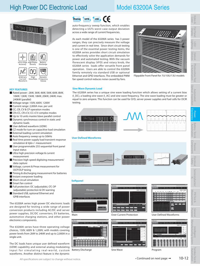
10-12All specifications are subject to change without notice. All specifications are subject to change without notice.
Flat PanelD
isplayPow
er Electronics
Electrical Safety
General
PurposePassive
Component
Semiconductor/
ICBattery Test & Autom
ationAutom
atedO
ptical Inspection Photovoltaic Test
& Automation
PXI Test &
Measurem
ent Video & Color
LED/
LightingO
ptical D
evicesIntelligent
Manufacturing System
Turnkey Test & Autom
ation High Power DC Electronic Load Model 63200A Series
KEY FEATURES Rated power : 2kW, 3kW, 4kW, 5kW, 6kW, 8kW, 10kW, 12kW, 15kW, 18kW, 20kW, 24kW, max. 240kW (parallel) Voltage range: 150V, 600V, 1200V Current range: 2,000A max. per unit CC, CR, CV & CP operation modes CR+CC, CR+CV, CC+CV complex modes Up to 10 units master/slave parallel control Dynamic synchronous control in static and dynamic loads User defined waveform (UDW) CZ mode for turn on capacitive load simulation External loading current simulation Auto frequency sweep up to 50kHz Real time power supply load transient response simulation & Vpk+/- measurement User programmable 255 sequential front panel input status Ultra high precision voltage & current measurement Precision high speed digitizing measurement/ data capture Voltage, current & Pmax measurement for OCP/OLP tesing Timing & discharging measurement for batteries Instant overpower loading Short circuit simulation Smart fan control Full protection: OC (adjustable), OT, OP (adjustable) protection & OV warning Standard USB, optional Ethernet and GPIB interfaces
The 63200A series high power DC electronic loads are designed for testing a wide range of power conversion products including AC/DC and server power supplies, DC/DC converters, EV batteries, automotive charging stations, and other power electronics components.
The 63200A series have three operating voltage choices, 150V, 600V & 1,200V, with models covering power levels from 2kW to 24kW and up to 2,000A in a single unit.
The DC loads have unique user defined waveform (UDW) capability and external analog modulating i n p u t f o r s i m u l a t i n g r e a l - w o r l d , c u s t o m waveforms. Another distinct feature is the dynamic
auto-frequency sweep function, which enables detecting a UUTs worst case output deviation across a wide range of current frequencies.
As each model of the 63200A series has 3 power ranges, they can precisely measure the voltage and current in real time. Since short circuit testing is one of the essential power testing items, the 63200A series provides short circuit simulation to effectively solve the application demands for power and automated testing. With the vacuum florescent display (VFD) and rotary knob, the 63200A series loads offer versatile front panel operation. Users are able to control the 63200A family remotely via standard USB or optional Ethernet and GPID interfaces. The embedded PWM fan speed control reduces noise caused by fans.
• Continued on next page
Softpanel
Main
Battery Discharge
Over Current Protection
Sine Wave
User Defined Waveforms
Program
User Defined Waveforms
Sine Wave Dynamic LoadThe 63200A series has a unique sine wave loading function which allows setting of a current bias (I_DC), a loading sine wave (I_AC) and sine wave frequency. The sine wave loading must be greater or equal to zero ampere. This function can be used for D/D, server power supplies and fuel cells for DCIR testing.
Flippable Front Panel for 7U/10U/13U models
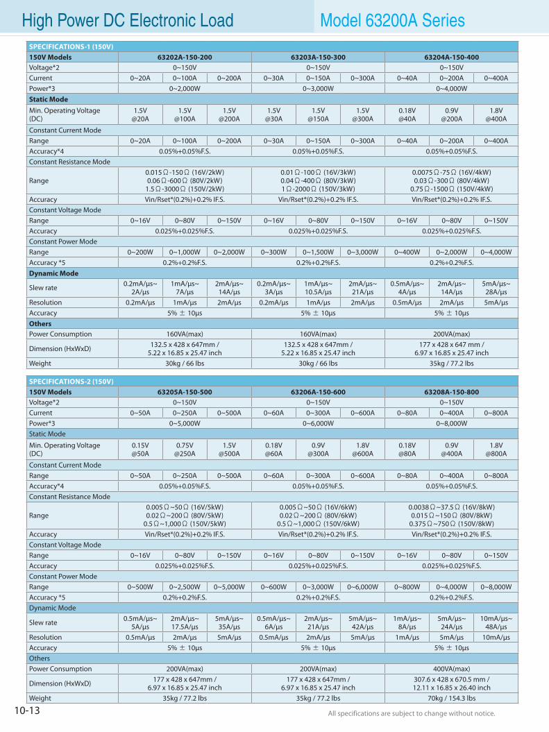
10-13 All specifications are subject to change without notice. All specifications are subject to change without notice.
High Power DC Electronic Load Model 63200A SeriesSPECIFICATIONS-1 (150V)150V Models 63202A-150-200 63203A-150-300 63204A-150-400Voltage*2 0~150V 0~150V 0~150VCurrent 0~20A 0~100A 0~200A 0~30A 0~150A 0~300A 0~40A 0~200A 0~400APower*3 0~2,000W 0~3,000W 0~4,000WStatic ModeMin. Operating Voltage(DC)
1.5V@20A
1.5V@100A
1.5V@200A
1.5V@30A
1.5V@150A
1.5V@300A
0.18V@40A
0.9V@200A
1.8V@400A
Constant Current ModeRange 0~20A 0~100A 0~200A 0~30A 0~150A 0~300A 0~40A 0~200A 0~400AAccuracy*4 0.05%+0.05%F.S. 0.05%+0.05%F.S. 0.05%+0.05%F.S.Constant Resistance Mode
Range0.015Ω-150Ω (16V/2kW)0.06Ω-600Ω (80V/2kW)
1.5Ω-3000Ω (150V/2kW)
0.01Ω-100Ω (16V/3kW)0.04Ω-400Ω (80V/3kW)1Ω-2000Ω (150V/3kW)
0.0075Ω-75Ω (16V/4kW)0.03Ω-300Ω (80V/4kW)
0.75Ω-1500Ω (150V/4kW)Accuracy Vin/Rset*(0.2%)+0.2% IF.S. Vin/Rset*(0.2%)+0.2% IF.S. Vin/Rset*(0.2%)+0.2% IF.S.Constant Voltage ModeRange 0~16V 0~80V 0~150V 0~16V 0~80V 0~150V 0~16V 0~80V 0~150VAccuracy 0.025%+0.025%F.S. 0.025%+0.025%F.S. 0.025%+0.025%F.S.Constant Power ModeRange 0~200W 0~1,000W 0~2,000W 0~300W 0~1,500W 0~3,000W 0~400W 0~2,000W 0~4,000WAccuracy *5 0.2%+0.2%F.S. 0.2%+0.2%F.S. 0.2%+0.2%F.S.Dynamic Mode
Slew rate 0.2mA/µs~2A/µs
1mA/µs~7A/µs
2mA/µs~14A/µs
0.2mA/µs~3A/µs
1mA/µs~10.5A/µs
2mA/µs~21A/µs
0.5mA/µs~4A/µs
2mA/µs~14A/µs
5mA/µs~28A/µs
Resolution 0.2mA/µs 1mA/µs 2mA/µs 0.2mA/µs 1mA/µs 2mA/µs 0.5mA/µs 2mA/µs 5mA/µsAccuracy 5% ± 10µs 5% ± 10µs 5% ± 10µsOthersPower Consumption 160VA(max) 160VA(max) 200VA(max)
Dimension (HxWxD) 132.5 x 428 x 647mm / 5.22 x 16.85 x 25.47 inch
132.5 x 428 x 647mm / 5.22 x 16.85 x 25.47 inch
177 x 428 x 647 mm / 6.97 x 16.85 x 25.47 inch
Weight 30kg / 66 lbs 30kg / 66 lbs 35kg / 77.2 lbs
SPECIFICATIONS-2 (150V)150V Models 63205A-150-500 63206A-150-600 63208A-150-800Voltage*2 0~150V 0~150V 0~150VCurrent 0~50A 0~250A 0~500A 0~60A 0~300A 0~600A 0~80A 0~400A 0~800APower*3 0~5,000W 0~6,000W 0~8,000WStatic Mode
Min. Operating Voltage(DC)
0.15V@50A
0.75V@250A
1.5V@500A
0.18V@60A
0.9V@300A
1.8V@600A
0.18V@80A
0.9V@400A
1.8V@800A
Constant Current ModeRange 0~50A 0~250A 0~500A 0~60A 0~300A 0~600A 0~80A 0~400A 0~800AAccuracy*4 0.05%+0.05%F.S. 0.05%+0.05%F.S. 0.05%+0.05%F.S.Constant Resistance Mode
Range0.005Ω~50Ω (16V/5kW)0.02Ω~200Ω (80V/5kW)
0.5Ω~1,000Ω (150V/5kW)
0.005Ω~50Ω (16V/6kW)0.02Ω~200Ω (80V/6kW)
0.5Ω~1,000Ω (150V/6kW)
0.0038Ω~37.5Ω (16V/8kW)0.015Ω~150Ω (80V/8kW)
0.375Ω~750Ω (150V/8kW)Accuracy Vin/Rset*(0.2%)+0.2% IF.S. Vin/Rset*(0.2%)+0.2% IF.S. Vin/Rset*(0.2%)+0.2% IF.S.Constant Voltage ModeRange 0~16V 0~80V 0~150V 0~16V 0~80V 0~150V 0~16V 0~80V 0~150VAccuracy 0.025%+0.025%F.S. 0.025%+0.025%F.S. 0.025%+0.025%F.S.Constant Power ModeRange 0~500W 0~2,500W 0~5,000W 0~600W 0~3,000W 0~6,000W 0~800W 0~4,000W 0~8,000WAccuracy *5 0.2%+0.2%F.S. 0.2%+0.2%F.S. 0.2%+0.2%F.S.Dynamic Mode
Slew rate 0.5mA/µs~5A/µs
2mA/µs~17.5A/µs
5mA/µs~35A/µs
0.5mA/µs~6A/µs
2mA/µs~21A/µs
5mA/µs~42A/µs
1mA/µs~8A/µs
5mA/µs~24A/µs
10mA/µs~48A/µs
Resolution 0.5mA/µs 2mA/µs 5mA/µs 0.5mA/µs 2mA/µs 5mA/µs 1mA/µs 5mA/µs 10mA/µsAccuracy 5% ± 10µs 5% ± 10µs 5% ± 10µsOthersPower Consumption 200VA(max) 200VA(max) 400VA(max)
Dimension (HxWxD) 177 x 428 x 647mm /6.97 x 16.85 x 25.47 inch
177 x 428 x 647mm /6.97 x 16.85 x 25.47 inch
307.6 x 428 x 670.5 mm /12.11 x 16.85 x 26.40 inch
Weight 35kg / 77.2 lbs 35kg / 77.2 lbs 70kg / 154.3 lbs
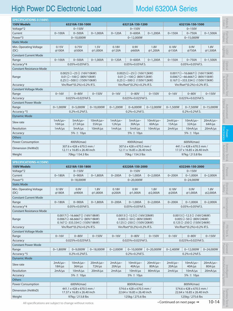
10-14All specifications are subject to change without notice. All specifications are subject to change without notice.
Flat PanelD
isplayPow
er Electronics
Electrical Safety
General
PurposePassive
Component
Semiconductor/
ICBattery Test & Autom
ationAutom
atedO
ptical Inspection Photovoltaic Test
& Automation
PXI Test &
Measurem
ent Video & Color
LED/
LightingO
ptical D
evicesIntelligent
Manufacturing System
Turnkey Test & Autom
ation High Power DC Electronic Load Model 63200A Series
• Continued on next page
SPECIFICATIONS-3 (150V)150V Models 63210A-150-1000 63212A-150-1200 63215A-150-1500Voltage*2 0~150V 0~150V 0~150VCurrent 0~100A 0~500A 0~1,000A 0~120A 0~600A 0~1,200A 0~150A 0~750A 0~1,500APower*3 0~10,000W 0~12,000W 0~15,000WStatic Mode
Min. Operating Voltage(DC)
0.15V@100A
0.75V@500A
1.5V@1,000A
0.18V@120A
0.9V@600A
1.8V@1,200A
0.18V@150A
0.9V@750A
1.8V@1,500A
Constant Current ModeRange 0~100A 0~500A 0~1,000A 0~120A 0~600A 0~1,200A 0~150A 0~750A 0~1,500AAccuracy*4 0.05%+0.05%F.S. 0.05%+0.05%F.S. 0.05%+0.05%F.S.Constant Resistance Mode
Range0.0025Ω~25Ω (16V/10kW)0.01Ω~100Ω (80V/10kW)
0.25Ω~500Ω (150V/10kW)
0.0025Ω~25Ω (16V/12kW)0.01Ω~100Ω (80V/12kW)
0.25Ω~500Ω (150V/12kW)
0.0017Ω~16.6667Ω (16V/15kW)0.0067Ω~66.6667Ω (80V/15kW)0.167Ω~333.334Ω (150V/15kW)
Accuracy Vin/Rset*(0.2%)+0.2% IF.S. Vin/Rset*(0.2%)+0.2% IF.S. Vin/Rset*(0.2%)+0.2% IF.S.Constant Voltage ModeRange 0~16V 0~80V 0~150V 0~16V 0~80V 0~150V 0~16V 0~80V 0~150VAccuracy 0.025%+0.025%F.S. 0.025%+0.025%F.S. 0.025%+0.025%F.S.Constant Power ModeRange 0~1,000W 0~5,000W 0~10,000W 0~1,200W 0~6,000W 0~12,000W 0~1,500W 0~7,500W 0~15,000WAccuracy *5 0.2%+0.2%F.S. 0.2%+0.2%F.S. 0.2%+0.2%F.S.Dynamic Mode
Slew rate 1mA/µs~10A/µs
5mA/µs~27.5A/µs
10mA/µs~55A/µs
1mA/µs~12A/µs
5mA/µs~30A/µs
10mA/µs~60A/µs
2mA/µs~15A/µs
10mA/µs~32A/µs
20mA/µs~64A/µs
Resolution 1mA/µs 5mA/µs 10mA/µs 1mA/µs 5mA/µs 10mA/µs 2mA/µs 10mA/µs 20mA/µsAccuracy 5% ± 10µs 5% ± 10µs 5% ± 10µsOthersPower Consumption 400VA(max) 400VA(max) 600VA(max)
Dimension (HxWxD) 307.6 x 428 x 670.5 mm /12.11 x 16.85 x 26.40 inch
307.6 x 428 x 670.5 mm /12.11 x 16.85 x 26.40 inch
441.1 x 428 x 670.5 mm /17.37 x 16.85 x 26.40 inch
Weight 70kg / 154.3 lbs 70kg / 154.3 lbs 97kg / 213.8 lbs
SPECIFICATIONS-4 (150V)150V Models 63218A-150-1800 63220A-150-2000 63224A-150-2000Voltage*2 0~150V 0~150V 0~150VCurrent 0~180A 0~900A 0~1,800A 0~200A 0~1,000A 0~2,000A 0~200A 0~1,000A 0~2,000APower*3 0~18,000W 0~20,000W 0~24,000WStatic Mode
Min. Operating Voltage(DC)
0.18V@180A
0.9V@900A
1.8V@1,800A
0.18V@200A
0.9V@1,000A
1.8V@2,000A
0.18V@200A
0.9V@1,000A
1.8V@2,000A
Constant Current ModeRange 0~180A 0~900A 0~1,800A 0~200A 0~1,000A 0~2,000A 0~200A 0~1,000A 0~2,000AAccuracy*4 0.05%+0.05%F.S. 0.05%+0.05%F.S. 0.05%+0.05%F.S.Constant Resistance Mode
Range0.0017Ω-16.6667Ω (16V/18kW)0.0067Ω-66.6667Ω (80V/18kW)0.167Ω-333.334Ω (150V/18kW)
0.0013Ω-12.5Ω (16V/20kW)0.005Ω-50Ω (80V/20kW)
0.125Ω-250Ω (150V/20kW)
0.0013Ω-12.5Ω (16V/24kW)0.005Ω-50Ω (80V/24kW)
0.125Ω-250Ω (150V/24kW)Accuracy Vin/Rset*(0.2%)+0.2% IF.S. Vin/Rset*(0.2%)+0.2% IF.S. Vin/Rset*(0.2%)+0.2% IF.S.Constant Voltage ModeRange 0~16V 0~80V 0~150V 0~16V 0~80V 0~150V 0~16V 0~80V 0~150VAccuracy 0.025%+0.025%F.S. 0.025%+0.025%F.S. 0.025%+0.025%F.S.Constant Power ModeRange 0~1,800W 0~9,000W 0~18,000W 0~2,000W 0~10,000W 0~20,000W 0~2,400W 0~12,000W 0~24,000WAccuracy *5 0.2%+0.2%F.S. 0.2%+0.2%F.S. 0.2%+0.2%F.S.Dynamic Mode
Slew rate 2mA/µs~18A/µs
10mA/µs~36A/µs
20mA/µs~72A/µs
2mA/µs~20A/µs
10mA/µs~40A/µs
20mA/µs~80A/µs
2mA/µs~20A/µs
10mA/µs~40A/µs
20mA/µs~80A/µs
Resolution 2mA/µs 10mA/µs 20mA/µs 2mA/µs 10mA/µs 80mA/µs 2mA/µs 10mA/µs 20mA/µsAccuracy 5% ± 10µs 5% ± 10µs 5% ± 10µsOthersPower Consumption 600VA(max) 800VA(max) 800VA(max)
Dimension (HxWxD) 441.1 x 428 x 670.5 mm /17.37 x 16.85 x 26.40 inch
574.6 x 428 x 670.5 mm /22.64 x 16.85 x 26.40 inch
574.6 x 428 x 670.5 mm /22.64 x 16.85 x 26.40 inch
Weight 97kg / 213.8 lbs 125kg / 275.6 lbs 125kg / 275.6 lbs
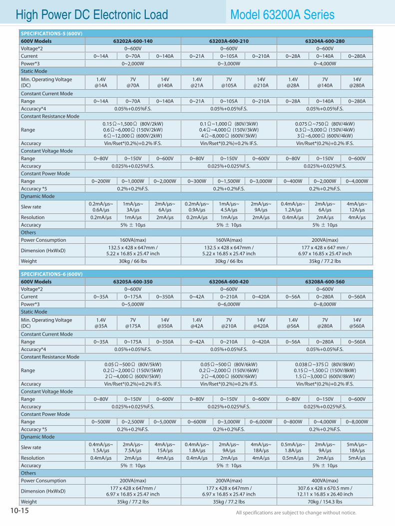
10-15 All specifications are subject to change without notice. All specifications are subject to change without notice.
High Power DC Electronic Load Model 63200A SeriesSPECIFICATIONS-5 (600V)600V Models 63202A-600-140 63203A-600-210 63204A-600-280Voltage*2 0~600V 0~600V 0~600VCurrent 0~14A 0~70A 0~140A 0~21A 0~105A 0~210A 0~28A 0~140A 0~280APower*3 0~2,000W 0~3,000W 0~4,000WStatic Mode
Min. Operating Voltage(DC)
1.4V@14A
7V@70A
14V@140A
1.4V@21A
7V@105A
14V@210A
1.4V@28A
7V@140A
14V@280A
Constant Current ModeRange 0~14A 0~70A 0~140A 0~21A 0~105A 0~210A 0~28A 0~140A 0~280AAccuracy*4 0.05%+0.05%F.S. 0.05%+0.05%F.S. 0.05%+0.05%F.S.Constant Resistance Mode
Range0.15Ω~1,500Ω (80V/2kW)0.6Ω~6,000Ω (150V/2kW)6Ω~12,000Ω (600V/2kW)
0.1Ω~1,000Ω (80V/3kW)0.4Ω~4,000Ω (150V/3kW)4Ω~8,000Ω (600V/3kW)
0.075Ω~750Ω (80V/4kW)0.3Ω~3,000Ω (150V/4kW)3Ω~6,000Ω (600V/4kW)
Accuracy Vin/Rset*(0.2%)+0.2% IF.S. Vin/Rset*(0.2%)+0.2% IF.S. Vin/Rset*(0.2%)+0.2% IF.S.Constant Voltage ModeRange 0~80V 0~150V 0~600V 0~80V 0~150V 0~600V 0~80V 0~150V 0~600VAccuracy 0.025%+0.025%F.S. 0.025%+0.025%F.S. 0.025%+0.025%F.S.Constant Power ModeRange 0~200W 0~1,000W 0~2,000W 0~300W 0~1,500W 0~3,000W 0~400W 0~2,000W 0~4,000WAccuracy *5 0.2%+0.2%F.S. 0.2%+0.2%F.S. 0.2%+0.2%F.S.Dynamic Mode
Slew rate 0.2mA/µs~0.6A/µs
1mA/µs~3A/µs
2mA/µs~6A/µs
0.2mA/µs~0.9A/µs
1mA/µs~4.5A/µs
2mA/µs~9A/µs
0.4mA/µs~1.2A/µs
2mA/µs~6A/µs
4mA/µs~12A/µs
Resolution 0.2mA/µs 1mA/µs 2mA/µs 0.2mA/µs 1mA/µs 2mA/µs 0.4mA/µs 2mA/µs 4mA/µsAccuracy 5% ± 10µs 5% ± 10µs 5% ± 10µsOthersPower Consumption 160VA(max) 160VA(max) 200VA(max)
Dimension (HxWxD) 132.5 x 428 x 647mm / 5.22 x 16.85 x 25.47 inch
132.5 x 428 x 647mm / 5.22 x 16.85 x 25.47 inch
177 x 428 x 647 mm / 6.97 x 16.85 x 25.47 inch
Weight 30kg / 66 lbs 30kg / 66 lbs 35kg / 77.2 lbs
SPECIFICATIONS-6 (600V)600V Models 63205A-600-350 63206A-600-420 63208A-600-560Voltage*2 0~600V 0~600V 0~600VCurrent 0~35A 0~175A 0~350A 0~42A 0~210A 0~420A 0~56A 0~280A 0~560APower*3 0~5,000W 0~6,000W 0~8,000WStatic Mode
Min. Operating Voltage(DC)
1.4V@35A
7V@175A
14V@350A
1.4V@42A
7V@210A
14V@420A
1.4V@56A
7V@280A
14V@560A
Constant Current ModeRange 0~35A 0~175A 0~350A 0~42A 0~210A 0~420A 0~56A 0~280A 0~560AAccuracy*4 0.05%+0.05%F.S. 0.05%+0.05%F.S. 0.05%+0.05%F.S.Constant Resistance Mode
Range0.05Ω~500Ω (80V/5kW)
0.2Ω~2,000Ω (150V/5kW)2Ω~4,000Ω (600V/5kW)
0.05Ω~500Ω (80V/6kW)0.2Ω~2,000Ω (150V/6kW)2Ω~4,000Ω (600V/6kW)
0.038Ω~375Ω (80V/8kW)0.15Ω~1,500Ω (150V/8kW)1.5Ω~3,000Ω (600V/8kW)
Accuracy Vin/Rset*(0.2%)+0.2% IF.S. Vin/Rset*(0.2%)+0.2% IF.S. Vin/Rset*(0.2%)+0.2% IF.S.Constant Voltage ModeRange 0~80V 0~150V 0~600V 0~80V 0~150V 0~600V 0~80V 0~150V 0~600VAccuracy 0.025%+0.025%F.S. 0.025%+0.025%F.S. 0.025%+0.025%F.S.Constant Power ModeRange 0~500W 0~2,500W 0~5,000W 0~600W 0~3,000W 0~6,000W 0~800W 0~4,000W 0~8,000WAccuracy *5 0.2%+0.2%F.S. 0.2%+0.2%F.S. 0.2%+0.2%F.S.Dynamic Mode
Slew rate 0.4mA/µs~1.5A/µs
2mA/µs~7.5A/µs
4mA/µs~15A/µs
0.4mA/µs~1.8A/µs
2mA/µs~9A/µs
4mA/µs~18A/µs
0.5mA/µs~1.8A/µs
2mA/µs~9A/µs
5mA/µs~18A/µs
Resolution 0.4mA/µs 2mA/µs 4mA/µs 0.4mA/µs 2mA/µs 4mA/µs 0.5mA/µs 2mA/µs 5mA/µsAccuracy 5% ± 10µs 5% ± 10µs 5% ± 10µsOthersPower Consumption 200VA(max) 200VA(max) 400VA(max)
Dimension (HxWxD) 177 x 428 x 647mm /6.97 x 16.85 x 25.47 inch
177 x 428 x 647mm /6.97 x 16.85 x 25.47 inch
307.6 x 428 x 670.5 mm /12.11 x 16.85 x 26.40 inch
Weight 35kg / 77.2 lbs 35kg / 77.2 lbs 70kg / 154.3 lbs
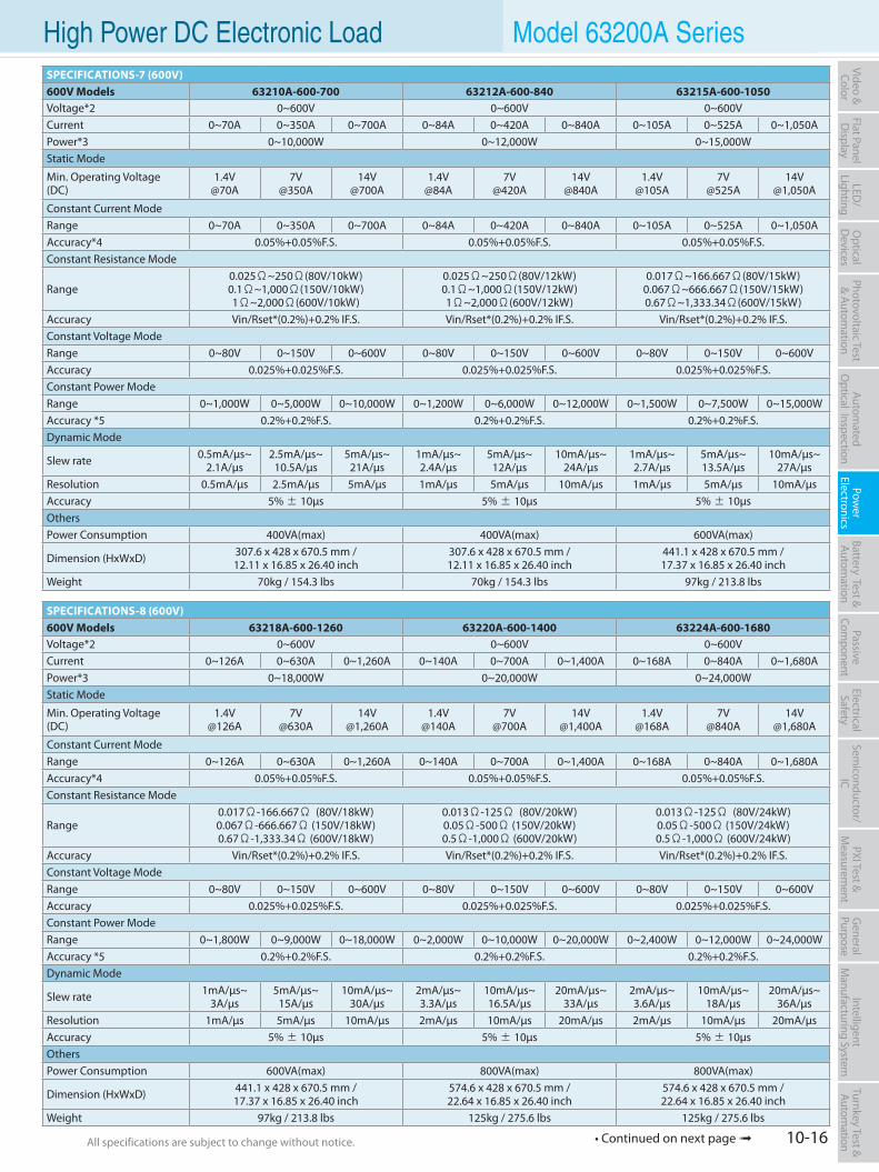
10-16All specifications are subject to change without notice. All specifications are subject to change without notice.
Flat PanelD
isplayPow
er Electronics
Electrical Safety
General
PurposePassive
Component
Semiconductor/
ICBattery Test & Autom
ationAutom
atedO
ptical Inspection Photovoltaic Test
& Automation
PXI Test &
Measurem
ent Video & Color
LED/
LightingO
ptical D
evicesIntelligent
Manufacturing System
Turnkey Test & Autom
ation High Power DC Electronic Load Model 63200A SeriesSPECIFICATIONS-7 (600V)600V Models 63210A-600-700 63212A-600-840 63215A-600-1050Voltage*2 0~600V 0~600V 0~600VCurrent 0~70A 0~350A 0~700A 0~84A 0~420A 0~840A 0~105A 0~525A 0~1,050APower*3 0~10,000W 0~12,000W 0~15,000WStatic Mode
Min. Operating Voltage(DC)
1.4V@70A
7V@350A
14V@700A
1.4V@84A
7V@420A
14V@840A
1.4V@105A
7V@525A
14V@1,050A
Constant Current ModeRange 0~70A 0~350A 0~700A 0~84A 0~420A 0~840A 0~105A 0~525A 0~1,050AAccuracy*4 0.05%+0.05%F.S. 0.05%+0.05%F.S. 0.05%+0.05%F.S.Constant Resistance Mode
Range0.025Ω~250Ω(80V/10kW)0.1Ω~1,000Ω(150V/10kW)1Ω~2,000Ω(600V/10kW)
0.025Ω~250Ω(80V/12kW)0.1Ω~1,000Ω(150V/12kW)1Ω~2,000Ω(600V/12kW)
0.017Ω~166.667Ω(80V/15kW)0.067Ω~666.667Ω(150V/15kW)0.67Ω~1,333.34Ω(600V/15kW)
Accuracy Vin/Rset*(0.2%)+0.2% IF.S. Vin/Rset*(0.2%)+0.2% IF.S. Vin/Rset*(0.2%)+0.2% IF.S.Constant Voltage ModeRange 0~80V 0~150V 0~600V 0~80V 0~150V 0~600V 0~80V 0~150V 0~600VAccuracy 0.025%+0.025%F.S. 0.025%+0.025%F.S. 0.025%+0.025%F.S.Constant Power ModeRange 0~1,000W 0~5,000W 0~10,000W 0~1,200W 0~6,000W 0~12,000W 0~1,500W 0~7,500W 0~15,000WAccuracy *5 0.2%+0.2%F.S. 0.2%+0.2%F.S. 0.2%+0.2%F.S.Dynamic Mode
Slew rate 0.5mA/µs~2.1A/µs
2.5mA/µs~10.5A/µs
5mA/µs~21A/µs
1mA/µs~2.4A/µs
5mA/µs~12A/µs
10mA/µs~24A/µs
1mA/µs~2.7A/µs
5mA/µs~13.5A/µs
10mA/µs~27A/µs
Resolution 0.5mA/µs 2.5mA/µs 5mA/µs 1mA/µs 5mA/µs 10mA/µs 1mA/µs 5mA/µs 10mA/µsAccuracy 5% ± 10µs 5% ± 10µs 5% ± 10µsOthersPower Consumption 400VA(max) 400VA(max) 600VA(max)
Dimension (HxWxD) 307.6 x 428 x 670.5 mm /12.11 x 16.85 x 26.40 inch
307.6 x 428 x 670.5 mm /12.11 x 16.85 x 26.40 inch
441.1 x 428 x 670.5 mm /17.37 x 16.85 x 26.40 inch
Weight 70kg / 154.3 lbs 70kg / 154.3 lbs 97kg / 213.8 lbs
SPECIFICATIONS-8 (600V)600V Models 63218A-600-1260 63220A-600-1400 63224A-600-1680Voltage*2 0~600V 0~600V 0~600VCurrent 0~126A 0~630A 0~1,260A 0~140A 0~700A 0~1,400A 0~168A 0~840A 0~1,680APower*3 0~18,000W 0~20,000W 0~24,000WStatic Mode
Min. Operating Voltage(DC)
1.4V@126A
7V@630A
14V@1,260A
1.4V@140A
7V@700A
14V@1,400A
1.4V@168A
7V@840A
14V@1,680A
Constant Current ModeRange 0~126A 0~630A 0~1,260A 0~140A 0~700A 0~1,400A 0~168A 0~840A 0~1,680AAccuracy*4 0.05%+0.05%F.S. 0.05%+0.05%F.S. 0.05%+0.05%F.S.Constant Resistance Mode
Range0.017Ω-166.667Ω (80V/18kW)0.067Ω-666.667Ω (150V/18kW)0.67Ω-1,333.34Ω (600V/18kW)
0.013Ω-125Ω (80V/20kW)0.05Ω-500Ω (150V/20kW)0.5Ω-1,000Ω (600V/20kW)
0.013Ω-125Ω (80V/24kW)0.05Ω-500Ω (150V/24kW)0.5Ω-1,000Ω (600V/24kW)
Accuracy Vin/Rset*(0.2%)+0.2% IF.S. Vin/Rset*(0.2%)+0.2% IF.S. Vin/Rset*(0.2%)+0.2% IF.S.Constant Voltage ModeRange 0~80V 0~150V 0~600V 0~80V 0~150V 0~600V 0~80V 0~150V 0~600VAccuracy 0.025%+0.025%F.S. 0.025%+0.025%F.S. 0.025%+0.025%F.S.Constant Power ModeRange 0~1,800W 0~9,000W 0~18,000W 0~2,000W 0~10,000W 0~20,000W 0~2,400W 0~12,000W 0~24,000WAccuracy *5 0.2%+0.2%F.S. 0.2%+0.2%F.S. 0.2%+0.2%F.S.Dynamic Mode
Slew rate 1mA/µs~3A/µs
5mA/µs~15A/µs
10mA/µs~30A/µs
2mA/µs~3.3A/µs
10mA/µs~16.5A/µs
20mA/µs~33A/µs
2mA/µs~3.6A/µs
10mA/µs~18A/µs
20mA/µs~36A/µs
Resolution 1mA/µs 5mA/µs 10mA/µs 2mA/µs 10mA/µs 20mA/µs 2mA/µs 10mA/µs 20mA/µsAccuracy 5% ± 10µs 5% ± 10µs 5% ± 10µsOthersPower Consumption 600VA(max) 800VA(max) 800VA(max)
Dimension (HxWxD) 441.1 x 428 x 670.5 mm /17.37 x 16.85 x 26.40 inch
574.6 x 428 x 670.5 mm /22.64 x 16.85 x 26.40 inch
574.6 x 428 x 670.5 mm /22.64 x 16.85 x 26.40 inch
Weight 97kg / 213.8 lbs 125kg / 275.6 lbs 125kg / 275.6 lbs
• Continued on next page
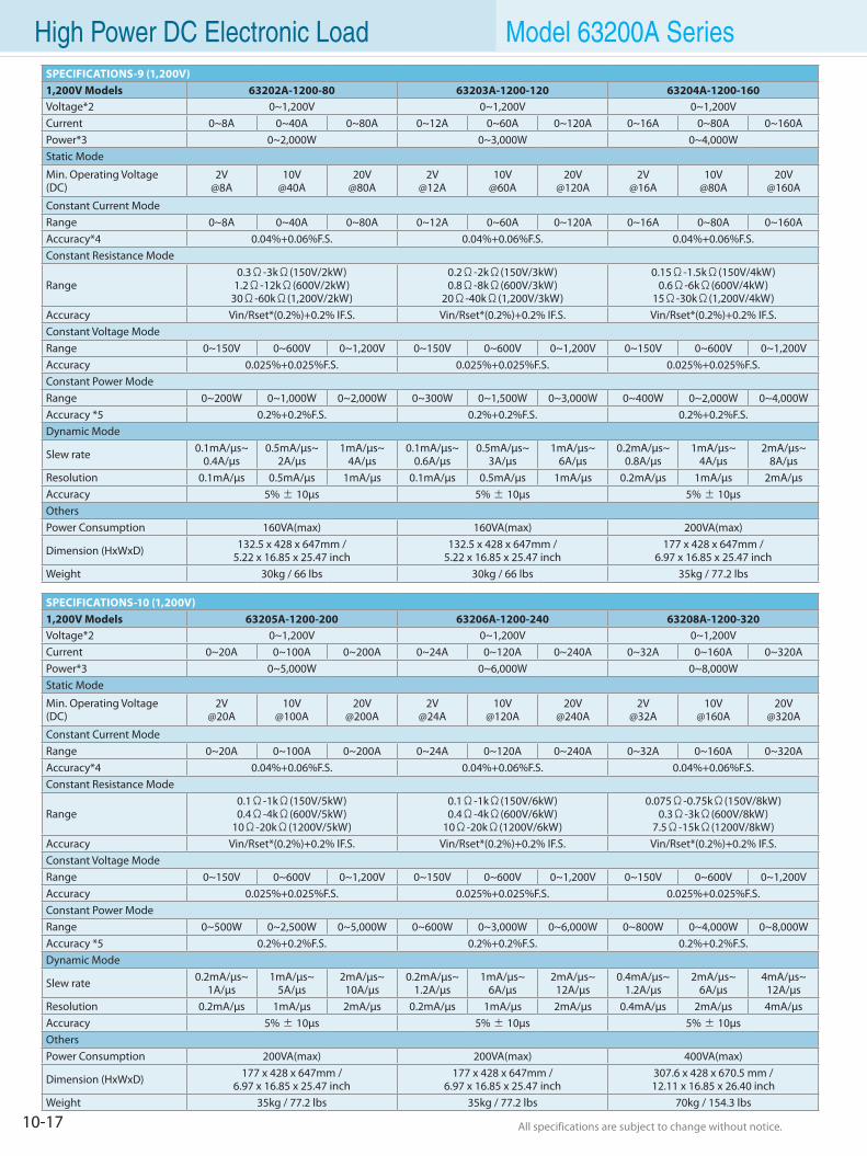
10-17 All specifications are subject to change without notice. All specifications are subject to change without notice.
High Power DC Electronic Load Model 63200A SeriesSPECIFICATIONS-9 (1,200V)1,200V Models 63202A-1200-80 63203A-1200-120 63204A-1200-160Voltage*2 0~1,200V 0~1,200V 0~1,200VCurrent 0~8A 0~40A 0~80A 0~12A 0~60A 0~120A 0~16A 0~80A 0~160APower*3 0~2,000W 0~3,000W 0~4,000WStatic Mode
Min. Operating Voltage(DC)
2V@8A
10V@40A
20V@80A
2V@12A
10V@60A
20V@120A
2V@16A
10V@80A
20V@160A
Constant Current ModeRange 0~8A 0~40A 0~80A 0~12A 0~60A 0~120A 0~16A 0~80A 0~160AAccuracy*4 0.04%+0.06%F.S. 0.04%+0.06%F.S. 0.04%+0.06%F.S.Constant Resistance Mode
Range0.3Ω-3kΩ(150V/2kW)
1.2Ω-12kΩ(600V/2kW)30Ω-60kΩ(1,200V/2kW)
0.2Ω-2kΩ(150V/3kW)0.8Ω-8kΩ(600V/3kW)
20Ω-40kΩ(1,200V/3kW)
0.15Ω-1.5kΩ(150V/4kW)0.6Ω-6kΩ(600V/4kW)
15Ω-30kΩ(1,200V/4kW)Accuracy Vin/Rset*(0.2%)+0.2% IF.S. Vin/Rset*(0.2%)+0.2% IF.S. Vin/Rset*(0.2%)+0.2% IF.S.Constant Voltage ModeRange 0~150V 0~600V 0~1,200V 0~150V 0~600V 0~1,200V 0~150V 0~600V 0~1,200VAccuracy 0.025%+0.025%F.S. 0.025%+0.025%F.S. 0.025%+0.025%F.S.Constant Power ModeRange 0~200W 0~1,000W 0~2,000W 0~300W 0~1,500W 0~3,000W 0~400W 0~2,000W 0~4,000WAccuracy *5 0.2%+0.2%F.S. 0.2%+0.2%F.S. 0.2%+0.2%F.S.Dynamic Mode
Slew rate 0.1mA/µs~0.4A/µs
0.5mA/µs~2A/µs
1mA/µs~4A/µs
0.1mA/µs~0.6A/µs
0.5mA/µs~3A/µs
1mA/µs~6A/µs
0.2mA/µs~0.8A/µs
1mA/µs~4A/µs
2mA/µs~8A/µs
Resolution 0.1mA/µs 0.5mA/µs 1mA/µs 0.1mA/µs 0.5mA/µs 1mA/µs 0.2mA/µs 1mA/µs 2mA/µsAccuracy 5% ± 10µs 5% ± 10µs 5% ± 10µsOthersPower Consumption 160VA(max) 160VA(max) 200VA(max)
Dimension (HxWxD) 132.5 x 428 x 647mm / 5.22 x 16.85 x 25.47 inch
132.5 x 428 x 647mm / 5.22 x 16.85 x 25.47 inch
177 x 428 x 647mm /6.97 x 16.85 x 25.47 inch
Weight 30kg / 66 lbs 30kg / 66 lbs 35kg / 77.2 lbs
SPECIFICATIONS-10 (1,200V)1,200V Models 63205A-1200-200 63206A-1200-240 63208A-1200-320Voltage*2 0~1,200V 0~1,200V 0~1,200VCurrent 0~20A 0~100A 0~200A 0~24A 0~120A 0~240A 0~32A 0~160A 0~320APower*3 0~5,000W 0~6,000W 0~8,000WStatic Mode
Min. Operating Voltage(DC)
2V@20A
10V@100A
20V@200A
2V@24A
10V@120A
20V@240A
2V@32A
10V@160A
20V@320A
Constant Current ModeRange 0~20A 0~100A 0~200A 0~24A 0~120A 0~240A 0~32A 0~160A 0~320AAccuracy*4 0.04%+0.06%F.S. 0.04%+0.06%F.S. 0.04%+0.06%F.S.Constant Resistance Mode
Range0.1Ω-1kΩ(150V/5kW)0.4Ω-4kΩ(600V/5kW)
10Ω-20kΩ(1200V/5kW)
0.1Ω-1kΩ(150V/6kW)0.4Ω-4kΩ(600V/6kW)
10Ω-20kΩ(1200V/6kW)
0.075Ω-0.75kΩ(150V/8kW)0.3Ω-3kΩ(600V/8kW)
7.5Ω-15kΩ(1200V/8kW)Accuracy Vin/Rset*(0.2%)+0.2% IF.S. Vin/Rset*(0.2%)+0.2% IF.S. Vin/Rset*(0.2%)+0.2% IF.S.Constant Voltage ModeRange 0~150V 0~600V 0~1,200V 0~150V 0~600V 0~1,200V 0~150V 0~600V 0~1,200VAccuracy 0.025%+0.025%F.S. 0.025%+0.025%F.S. 0.025%+0.025%F.S.Constant Power ModeRange 0~500W 0~2,500W 0~5,000W 0~600W 0~3,000W 0~6,000W 0~800W 0~4,000W 0~8,000WAccuracy *5 0.2%+0.2%F.S. 0.2%+0.2%F.S. 0.2%+0.2%F.S.Dynamic Mode
Slew rate 0.2mA/µs~1A/µs
1mA/µs~5A/µs
2mA/µs~10A/µs
0.2mA/µs~1.2A/µs
1mA/µs~6A/µs
2mA/µs~12A/µs
0.4mA/µs~1.2A/µs
2mA/µs~6A/µs
4mA/µs~12A/µs
Resolution 0.2mA/µs 1mA/µs 2mA/µs 0.2mA/µs 1mA/µs 2mA/µs 0.4mA/µs 2mA/µs 4mA/µsAccuracy 5% ± 10µs 5% ± 10µs 5% ± 10µsOthersPower Consumption 200VA(max) 200VA(max) 400VA(max)
Dimension (HxWxD) 177 x 428 x 647mm /6.97 x 16.85 x 25.47 inch
177 x 428 x 647mm /6.97 x 16.85 x 25.47 inch
307.6 x 428 x 670.5 mm /12.11 x 16.85 x 26.40 inch
Weight 35kg / 77.2 lbs 35kg / 77.2 lbs 70kg / 154.3 lbs

10-18All specifications are subject to change without notice. All specifications are subject to change without notice.
Flat PanelD
isplayPow
er Electronics
Electrical Safety
General
PurposePassive
Component
Semiconductor/
ICBattery Test & Autom
ationAutom
atedO
ptical Inspection Photovoltaic Test
& Automation
PXI Test &
Measurem
ent Video & Color
LED/
LightingO
ptical D
evicesIntelligent
Manufacturing System
Turnkey Test & Autom
ation High Power DC Electronic Load Model 63200A SeriesSPECIFICATIONS-11 (1,200V)1,200V Models 63210A-1200-400 63212A-1200-480 63215A-1200-600Voltage*2 0~1,200V 0~1,200V 0~1,200VCurrent 0~40A 0~200A 0~400A 0~48A 0~240A 0~480A 0~60A 0~300A 0~600APower*3 0~10,000W 0~12,000W 0~15,000WStatic Mode
Min. Operating Voltage(DC)
2V@40A
10V@200A
20V@400A
2V@48A
10V@240A
20V@480A
2V@60A
10V@300A
20V@600A
Constant Current ModeRange 0~40A 0~200A 0~400A 0~48A 0~240A 0~480A 0~60A 0~300A 0~600AAccuracy*4 0.04%+0.06%F.S. 0.04%+0.06%F.S. 0.04%+0.06%F.S.Constant Resistance Mode
Range0.05Ω~0.5kΩ(150V/10kW)
0.2Ω~2kΩ(600V/10kW)5Ω~10kΩ(1,200V/10kW)
0.05Ω~0.5kΩ(150V/12kW)0.2Ω~2kΩ(600V/12kW)
5Ω~10kΩ(1,200V/12kW)
0.034Ω~0.333334kΩ(150V/15kW)0.14Ω~1.33334kΩ(600V/15kW)
3.34Ω~6.66667kΩ(1,200V/15kW)Accuracy Vin/Rset*(0.2%)+0.2% IF.S. Vin/Rset*(0.2%)+0.2% IF.S. Vin/Rset*(0.2%)+0.2% IF.S.Constant Voltage ModeRange 0~150V 0~600V 0~1,200V 0~150V 0~600V 0~1,200V 0~150V 0~600V 0~1,200VAccuracy 0.025%+0.025%F.S. 0.025%+0.025%F.S. 0.025%+0.025%F.S.Constant Power ModeRange 0~1,000W 0~5,000W 0~10,000W 0~1,200W 0~6,000W 0~12,000W 0~1,500W 0~7,500W 0~15,000WAccuracy *5 0.2%+0.2%F.S. 0.2%+0.2%F.S. 0.2%+0.2%F.S.Dynamic Mode
Slew rate 0.4mA/µs~1.4A/µs
2mA/µs~7A/µs
4mA/µs~14A/µs
0.4mA/µs~1.6A/µs
2mA/µs~8A/µs
4mA/µs~16A/µs
0.5mA/µs~1.8A/µs
2mA/µs~9A/µs
5mA/µs~18A/µs
Resolution 0.4mA/µs 2mA/µs 4mA/µs 0.4mA/µs 2mA/µs 4mA/µs 0.5mA/µs 2mA/µs 5mA/µsAccuracy 5% ± 10µs 5% ± 10µs 5% ± 10µsOthersPower Consumption 400VA(max) 400VA(max) 600VA(max)
Dimension (HxWxD) 307.6 x 428 x 670.5 mm /12.11 x 16.85 x 26.40 inch
307.6 x 428 x 670.5 mm /12.11 x 16.85 x 26.40 inch
441.1 x 428 x 670.5 mm /17.37 x 16.85 x 26.40 inch
Weight 70kg / 154.3 lbs 70kg / 154.3 lbs 97kg / 213.8 lbs
SPECIFICATIONS-12 (1,200V)1,200V Models 63218A-1200-720 63220A-1200-800 63224A-1200-960Voltage*2 0~1,200V 0~1,200V 0~1,200VCurrent 0~72A 0~360A 0~720A 0~80A 0~400A 0~800A 0~96A 0~480A 0~960APower*3 0~18,000W 0~20,000W 0~24,000WStatic Mode
Min. Operating Voltage(DC)
2V@72A
10V@360A
20V@720A
2V@80A
10V@400A
20V@800A
2V@96A
10V@480A
20V@960A
Constant Current ModeRange 0~72A 0~360A 0~720A 0~80A 0~400A 0~800A 0~96A 0~480A 0~960AAccuracy*4 0.04%+0.06%F.S. 0.04%+0.06%F.S. 0.04%+0.06%F.S.Constant Resistance Mode
Range0.034Ω~0.333334kΩ(150V/18kW)
0.14Ω~1.33334kΩ(600V/18kW)3.34Ω~6.66667kΩ(1,200V/18kW)
0.025Ω~0.25kΩ(150V/20kW)0.1Ω~1kΩ(600V/20kW)
2.5Ω~5kΩ(1,200V/20kW)
0.025Ω~0.25kΩ(150V/24kW)0.1Ω~1kΩ(600V/24kW)
2.5Ω~5kΩ(1,200V/24kW)Accuracy Vin/Rset*(0.2%)+0.2% IF.S. Vin/Rset*(0.2%)+0.2% IF.S. Vin/Rset*(0.2%)+0.2% IF.S.Constant Voltage ModeRange 0~150V 0~600V 0~1,200V 0~150V 0~600V 0~1,200V 0~150V 0~600V 0~1,200VAccuracy 0.025%+0.025%F.S. 0.025%+0.025%F.S. 0.025%+0.025%F.S.Constant Power ModeRange 0~1,800W 0~9,000W 0~18,000W 0~2,000W 0~10,000W 0~20,000W 0~2,400W 0~12,000W 0~24,000WAccuracy *5 0.2%+0.2%F.S. 0.2%+0.2%F.S. 0.2%+0.2%F.S.Dynamic Mode
Slew rate 0.5mA/µs~2A/µs
2mA/µs~10A/µs
5mA/µs~20A/µs
1mA/µs~2.2A/µs
5mA/µs~11A/µs
10mA/µs~22A/µs
1mA/µs~2.4A/µs
5mA/µs~12A/µs
10mA/µs~24A/µs
Resolution 0.5mA/µs 2mA/µs 5mA/µs 1mA/µs 5mA/µs 10mA/µs 1mA/µs 5mA/µs 10mA/µsAccuracy 5% ± 10µs 5% ± 10µs 5% ± 10µsOthersPower Consumption 600VA(max) 800VA(max) 800VA(max)
Dimension (HxWxD) 441.1 x 428 x 670.5 mm /17.37 x 16.85 x 26.40 inch
574.6 x 428 x 670.5 mm /22.64 x 16.85 x 26.40 inch
574.6 x 428 x 670.5 mm /22.64 x 16.85 x 26.40 inch
Weight 97kg / 213.8 lbs 125kg / 275.6 lbs 125kg / 275.6 lbs
• Continued on next page
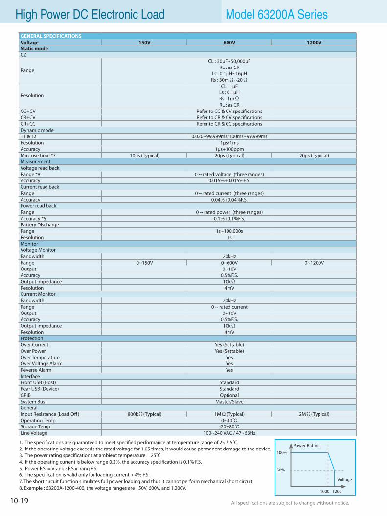
10-19 All specifications are subject to change without notice. All specifications are subject to change without notice.
High Power DC Electronic Load Model 63200A Series
1. The specifications are guaranteed to meet specified performance at temperature range of 25±5˚C.2. If the operating voltage exceeds the rated voltage for 1.05 times, it would cause permanent damage to the device.3. The power rating specifications at ambient temperature = 25˚C.4. If the operating current is below range 0.2%, the accuracy specification is 0.1% F.S.5. Power F.S. = Vrange F.S.x Irang F.S.6. The specification is valid only for loading current > 4% F.S.7. The short circuit function simulates full power loading and thus it cannot perform mechanical short circuit.8. Example : 63200A-1200-400, the voltage ranges are 150V, 600V, and 1,200V.
Power Rating
100%
50%
Voltage
1000 1200
GENERAL SPECIFICATIONSVoltage 150V 600V 1200VStatic modeCZ
Range
CL : 30µF~50,000µF RL : as CR
Ls : 0.1µH~16µH Rs : 30mΩ~20Ω
Resolution
CL : 1µFLs : 0.1µHRs : 1mΩRL : as CR
CC+CV Refer to CC & CV specificationsCR+CV Refer to CR & CV specificationsCR+CC Refer to CR & CC specificationsDynamic modeT1 & T2 0.020~99.999ms/100ms~99,999msResolution 1µs/1msAccuracy 1µs+100ppmMin. rise time *7 10µs (Typical) 20µs (Typical) 20µs (Typical)Measurement Voltage read backRange *8 0 ~ rated voltage (three ranges)Accuracy 0.015%+0.015%F.S.Current read backRange 0 ~ rated current (three ranges)Accuracy 0.04%+0.04%F.S.Power read backRange 0 ~ rated power (three ranges)Accuracy *5 0.1%+0.1%F.S.Battery Discharge Range 1s~100,000sResolution 1sMonitorVoltage MonitorBandwidth 20kHzRange 0~150V 0~600V 0~1200VOutput 0~10VAccuracy 0.5%F.S.Output impedance 10kΩResolution 4mVCurrent MonitorBandwidth 20kHzRange 0 ~ rated currentOutput 0~10VAccuracy 0.5%F.S.Output impedance 10kΩResolution 4mVProtectionOver Current Yes (Settable)Over Power Yes (Settable)Over Temperature YesOver Voltage Alarm YesReverse Alarm YesInterfaceFront USB (Host) StandardRear USB (Device) StandardGPIB OptionalSystem Bus Master/SlaveGeneralInput Resistance (Load Off) 800kΩ(Typical) 1MΩ(Typical) 2MΩ(Typical)Operating Temp 0~40Storage Temp -20~80Line Voltage 100~240 VAC / 47~63Hz
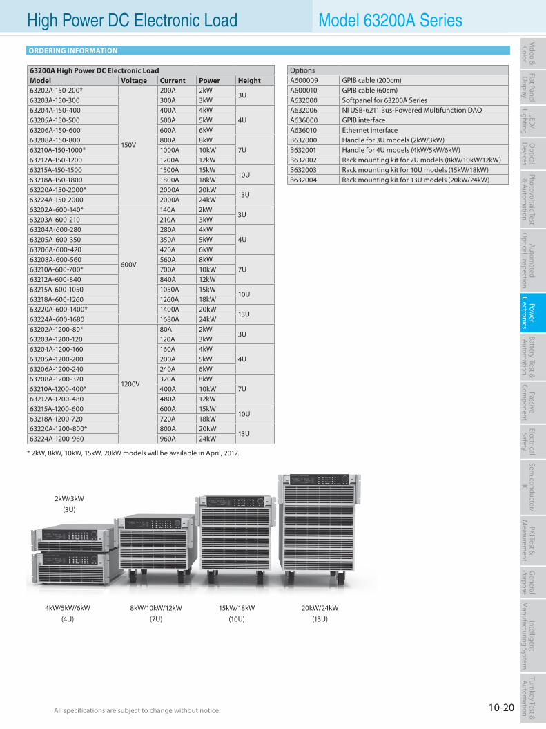
10-20All specifications are subject to change without notice. All specifications are subject to change without notice.
Flat PanelD
isplayPow
er Electronics
Electrical Safety
General
PurposePassive
Component
Semiconductor/
ICBattery Test & Autom
ationAutom
atedO
ptical Inspection Photovoltaic Test
& Automation
PXI Test &
Measurem
ent Video & Color
LED/
LightingO
ptical D
evicesIntelligent
Manufacturing System
Turnkey Test & Autom
ation High Power DC Electronic Load Model 63200A Series
ORDERING INFORMATION
OptionsA600009 GPIB cable (200cm)A600010 GPIB cable (60cm)A632000 Softpanel for 63200A SeriesA632006 NI USB-6211 Bus-Powered Multifunction DAQA636000 GPIB interfaceA636010 Ethernet interfaceB632000 Handle for 3U models (2kW/3kW)B632001 Handle for 4U models (4kW/5kW/6kW)B632002 Rack mounting kit for 7U models (8kW/10kW/12kW)B632003 Rack mounting kit for 10U models (15kW/18kW)B632004 Rack mounting kit for 13U models (20kW/24kW)
* 2kW, 8kW, 10kW, 15kW, 20kW models will be available in April, 2017.
63200A High Power DC Electronic Load Model Voltage Current Power Height63202A-150-200*
150V
200A 2kW3U
63203A-150-300 300A 3kW63204A-150-400 400A 4kW
4U63205A-150-500 500A 5kW63206A-150-600 600A 6kW63208A-150-800 800A 8kW
7U63210A-150-1000* 1000A 10kW63212A-150-1200 1200A 12kW63215A-150-1500 1500A 15kW
10U63218A-150-1800 1800A 18kW63220A-150-2000* 2000A 20kW
13U63224A-150-2000 2000A 24kW63202A-600-140*
600V
140A 2kW3U
63203A-600-210 210A 3kW63204A-600-280 280A 4kW
4U63205A-600-350 350A 5kW63206A-600-420 420A 6kW63208A-600-560 560A 8kW
7U63210A-600-700* 700A 10kW63212A-600-840 840A 12kW63215A-600-1050 1050A 15kW
10U63218A-600-1260 1260A 18kW63220A-600-1400* 1400A 20kW
13U63224A-600-1680 1680A 24kW63202A-1200-80*
1200V
80A 2kW3U
63203A-1200-120 120A 3kW63204A-1200-160 160A 4kW
4U63205A-1200-200 200A 5kW63206A-1200-240 240A 6kW63208A-1200-320 320A 8kW
7U63210A-1200-400* 400A 10kW63212A-1200-480 480A 12kW63215A-1200-600 600A 15kW
10U63218A-1200-720 720A 18kW63220A-1200-800* 800A 20kW
13U63224A-1200-960 960A 24kW
4kW/5kW/6kW(4U)
15kW/18kW(10U)
8kW/10kW/12kW(7U)
20kW/24kW(13U)
2kW/3kW(3U)
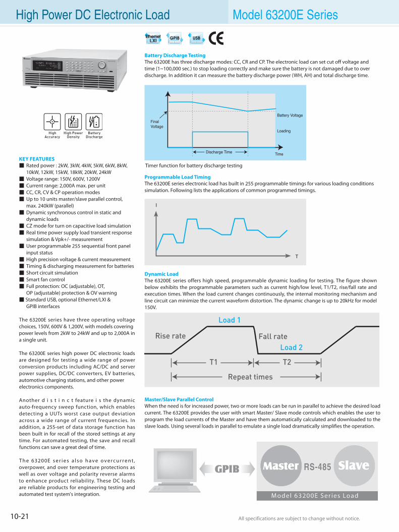
10-21 All specifications are subject to change without notice. All specifications are subject to change without notice.
High Power DC Electronic Load Model 63200E Series
KEY FEATURES Rated power : 2kW, 3kW, 4kW, 5kW, 6kW, 8kW, 10kW, 12kW, 15kW, 18kW, 20kW, 24kW Voltage range: 150V, 600V, 1200V Current range: 2,000A max. per unit CC, CR, CV & CP operation modes Up to 10 units master/slave parallel control, max. 240kW (parallel) Dynamic synchronous control in static and dynamic loads CZ mode for turn on capacitive load simulation Real time power supply load transient response simulation & Vpk+/- measurement User programmable 255 sequential front panel input status High precision voltage & current measurement Timing & discharging measurement for batteries Short circuit simulation Smart fan control Full protection: OC (adjustable), OT, OP (adjustable) protection & OV warning Standard USB, optional Ethernet/LXI & GPIB interfaces
The 63200E series have three operating voltage choices, 150V, 600V & 1,200V, with models coveringpower levels from 2kW to 24kW and up to 2,000A in a single unit.
The 63200E series high power DC electronic loads are designed for testing a wide range of power conversion products including AC/DC and server power supplies, DC/DC converters, EV batteries, automotive charging stations, and other powerelectronics components.
Another d i s t i n c t feature i s the dynamic auto-frequency sweep function, which enables detecting a UUTs worst case output deviation across a wide range of current frequencies. In addition, a 255-set of data storage function has been built in for recall of the stored settings at any time. For automated testing, the save and recall functions can save a great deal of time.
T h e 63200E s e r i e s a l s o h a v e o v e r c u r r e n t, overpower, and over temperature protections as well as over voltage and polarity reverse alarms to enhance product reliability. These DC loads are reliable products for engineering testing and automated test system's integration.
Battery Discharge TestingThe 63200E has three discharge modes: CC, CR and CP. The electronic load can set cut off voltage andtime (1~100,000 sec.) to stop loading correctly and make sure the battery is not damaged due to overdischarge. In addition it can measure the battery discharge power (WH, AH) and total discharge time.
Timer function for battery discharge testing
T
Master/Slave Parallel ControlWhen the need is for increased power, two or more loads can be run in parallel to achieve the desired load current. The 63200E provides the user with smart Master/ Slave mode controls which enables the user to program the load currents of the Master and have them automatically calculated and downloaded to the slave loads. Using several loads in parallel to emulate a single load dramatically simplifies the operation.
Programmable Load TimingThe 63200E series electronic load has built in 255 programmable timings for various loading conditionssimulation. Following lists the applications of common programmed timings.
Dynamic LoadThe 63200E series offers high speed, programmable dynamic loading for testing. The figure shown below exhibits the programmable parameters such as current high/low level, T1/T2, rise/fall rate and execution times. When the load current changes continuously, the internal monitoring mechanism and line circuit can minimize the current waveform distortion. The dynamic change is up to 20kHz for model 150V.
I
T1
Repeat times
T2
Load 1
Load 2Fall rateRise rate
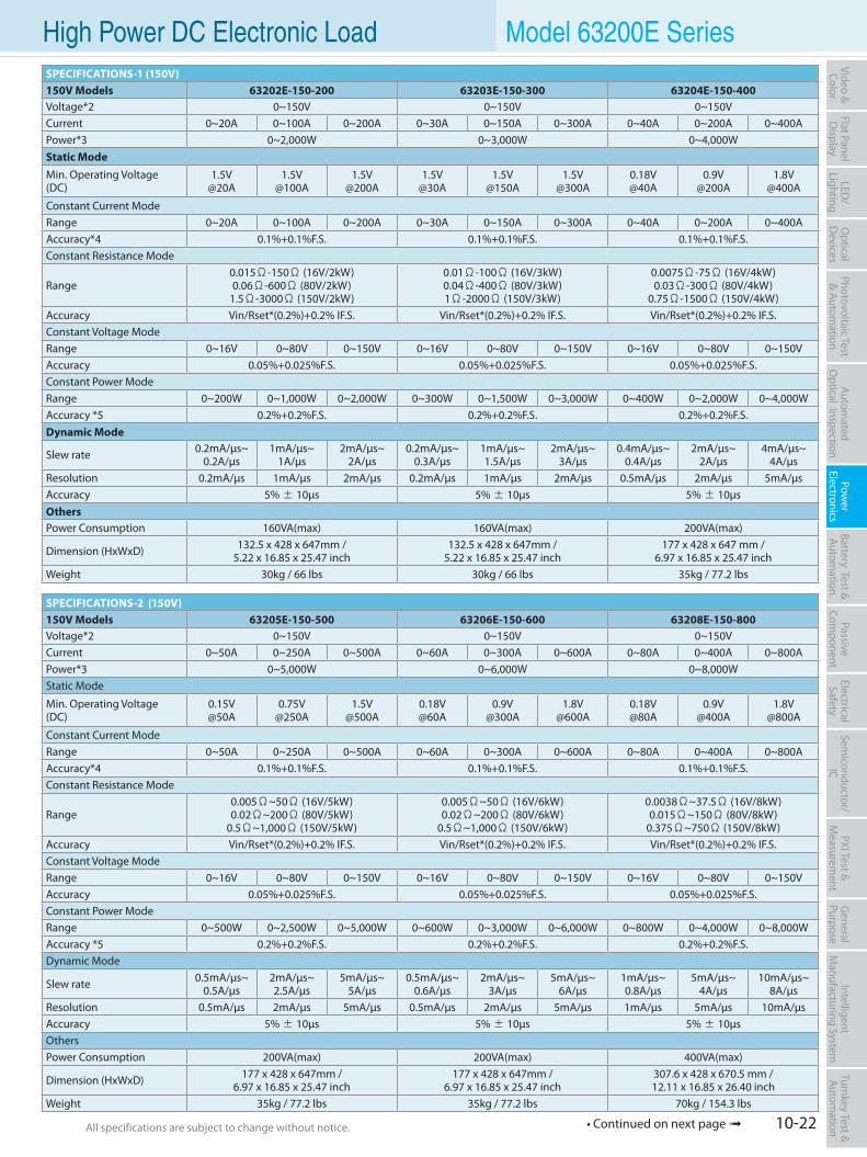
10-22All specifications are subject to change without notice. All specifications are subject to change without notice.
Flat PanelD
isplayPow
er Electronics
Electrical Safety
General
PurposePassive
Component
Semiconductor/
ICBattery Test & Autom
ationAutom
atedO
ptical Inspection Photovoltaic Test
& Automation
PXI Test &
Measurem
ent Video & Color
LED/
LightingO
ptical D
evicesIntelligent
Manufacturing System
Turnkey Test & Autom
ation High Power DC Electronic Load Model 63200E SeriesSPECIFICATIONS-1 (150V)150V Models 63202E-150-200 63203E-150-300 63204E-150-400Voltage*2 0~150V 0~150V 0~150VCurrent 0~20A 0~100A 0~200A 0~30A 0~150A 0~300A 0~40A 0~200A 0~400APower*3 0~2,000W 0~3,000W 0~4,000WStatic ModeMin. Operating Voltage(DC)
1.5V@20A
1.5V@100A
1.5V@200A
1.5V@30A
1.5V@150A
1.5V@300A
0.18V@40A
0.9V@200A
1.8V@400A
Constant Current ModeRange 0~20A 0~100A 0~200A 0~30A 0~150A 0~300A 0~40A 0~200A 0~400AAccuracy*4 0.1%+0.1%F.S. 0.1%+0.1%F.S. 0.1%+0.1%F.S.Constant Resistance Mode
Range0.015Ω-150Ω (16V/2kW)0.06Ω-600Ω (80V/2kW)
1.5Ω-3000Ω (150V/2kW)
0.01Ω-100Ω (16V/3kW)0.04Ω-400Ω (80V/3kW)1Ω-2000Ω (150V/3kW)
0.0075Ω-75Ω (16V/4kW)0.03Ω-300Ω (80V/4kW)
0.75Ω-1500Ω (150V/4kW)Accuracy Vin/Rset*(0.2%)+0.2% IF.S. Vin/Rset*(0.2%)+0.2% IF.S. Vin/Rset*(0.2%)+0.2% IF.S.Constant Voltage ModeRange 0~16V 0~80V 0~150V 0~16V 0~80V 0~150V 0~16V 0~80V 0~150VAccuracy 0.05%+0.025%F.S. 0.05%+0.025%F.S. 0.05%+0.025%F.S.Constant Power ModeRange 0~200W 0~1,000W 0~2,000W 0~300W 0~1,500W 0~3,000W 0~400W 0~2,000W 0~4,000WAccuracy *5 0.2%+0.2%F.S. 0.2%+0.2%F.S. 0.2%+0.2%F.S.Dynamic Mode
Slew rate 0.2mA/µs~0.2A/µs
1mA/µs~1A/µs
2mA/µs~2A/µs
0.2mA/µs~0.3A/µs
1mA/µs~1.5A/µs
2mA/µs~3A/µs
0.4mA/µs~0.4A/µs
2mA/µs~2A/µs
4mA/µs~4A/µs
Resolution 0.2mA/µs 1mA/µs 2mA/µs 0.2mA/µs 1mA/µs 2mA/µs 0.5mA/µs 2mA/µs 5mA/µsAccuracy 5% ± 10µs 5% ± 10µs 5% ± 10µsOthersPower Consumption 160VA(max) 160VA(max) 200VA(max)
Dimension (HxWxD) 132.5 x 428 x 647mm / 5.22 x 16.85 x 25.47 inch
132.5 x 428 x 647mm / 5.22 x 16.85 x 25.47 inch
177 x 428 x 647 mm / 6.97 x 16.85 x 25.47 inch
Weight 30kg / 66 lbs 30kg / 66 lbs 35kg / 77.2 lbs
SPECIFICATIONS-2 (150V)150V Models 63205E-150-500 63206E-150-600 63208E-150-800Voltage*2 0~150V 0~150V 0~150VCurrent 0~50A 0~250A 0~500A 0~60A 0~300A 0~600A 0~80A 0~400A 0~800APower*3 0~5,000W 0~6,000W 0~8,000WStatic Mode
Min. Operating Voltage(DC)
0.15V@50A
0.75V@250A
1.5V@500A
0.18V@60A
0.9V@300A
1.8V@600A
0.18V@80A
0.9V@400A
1.8V@800A
Constant Current ModeRange 0~50A 0~250A 0~500A 0~60A 0~300A 0~600A 0~80A 0~400A 0~800AAccuracy*4 0.1%+0.1%F.S. 0.1%+0.1%F.S. 0.1%+0.1%F.S.Constant Resistance Mode
Range0.005Ω~50Ω (16V/5kW)0.02Ω~200Ω (80V/5kW)
0.5Ω~1,000Ω (150V/5kW)
0.005Ω~50Ω (16V/6kW)0.02Ω~200Ω (80V/6kW)
0.5Ω~1,000Ω (150V/6kW)
0.0038Ω~37.5Ω (16V/8kW)0.015Ω~150Ω (80V/8kW)
0.375Ω~750Ω (150V/8kW)Accuracy Vin/Rset*(0.2%)+0.2% IF.S. Vin/Rset*(0.2%)+0.2% IF.S. Vin/Rset*(0.2%)+0.2% IF.S.Constant Voltage ModeRange 0~16V 0~80V 0~150V 0~16V 0~80V 0~150V 0~16V 0~80V 0~150VAccuracy 0.05%+0.025%F.S. 0.05%+0.025%F.S. 0.05%+0.025%F.S.Constant Power ModeRange 0~500W 0~2,500W 0~5,000W 0~600W 0~3,000W 0~6,000W 0~800W 0~4,000W 0~8,000WAccuracy *5 0.2%+0.2%F.S. 0.2%+0.2%F.S. 0.2%+0.2%F.S.Dynamic Mode
Slew rate 0.5mA/µs~0.5A/µs
2mA/µs~2.5A/µs
5mA/µs~5A/µs
0.5mA/µs~0.6A/µs
2mA/µs~3A/µs
5mA/µs~6A/µs
1mA/µs~0.8A/µs
5mA/µs~4A/µs
10mA/µs~8A/µs
Resolution 0.5mA/µs 2mA/µs 5mA/µs 0.5mA/µs 2mA/µs 5mA/µs 1mA/µs 5mA/µs 10mA/µsAccuracy 5% ± 10µs 5% ± 10µs 5% ± 10µsOthersPower Consumption 200VA(max) 200VA(max) 400VA(max)
Dimension (HxWxD) 177 x 428 x 647mm /6.97 x 16.85 x 25.47 inch
177 x 428 x 647mm /6.97 x 16.85 x 25.47 inch
307.6 x 428 x 670.5 mm /12.11 x 16.85 x 26.40 inch
Weight 35kg / 77.2 lbs 35kg / 77.2 lbs 70kg / 154.3 lbs
• Continued on next page
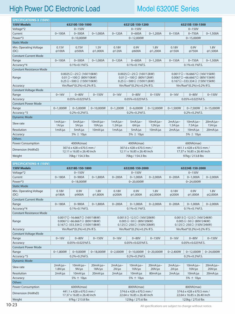
10-23 All specifications are subject to change without notice. All specifications are subject to change without notice.
High Power DC Electronic Load Model 63200E SeriesSPECIFICATIONS-3 (150V)150V Models 63210E-150-1000 63212E-150-1200 63215E-150-1500Voltage*2 0~150V 0~150V 0~150VCurrent 0~100A 0~500A 0~1,000A 0~120A 0~600A 0~1,200A 0~150A 0~750A 0~1,500APower*3 0~10,000W 0~12,000W 0~15,000WStatic Mode
Min. Operating Voltage(DC)
0.15V@100A
0.75V@500A
1.5V@1,000A
0.18V@120A
0.9V@600A
1.8V@1,200A
0.18V@150A
0.9V@750A
1.8V@1,500A
Constant Current ModeRange 0~100A 0~500A 0~1,000A 0~120A 0~600A 0~1,200A 0~150A 0~750A 0~1,500AAccuracy*4 0.1%+0.1%F.S. 0.1%+0.1%F.S. 0.1%+0.1%F.S.Constant Resistance Mode
Range0.0025Ω~25Ω (16V/10kW)0.01Ω~100Ω (80V/10kW)
0.25Ω~500Ω (150V/10kW)
0.0025Ω~25Ω (16V/12kW)0.01Ω~100Ω (80V/12kW)
0.25Ω~500Ω (150V/12kW)
0.0017Ω~16.6667Ω (16V/15kW)0.0067Ω~66.6667Ω (80V/15kW)0.167Ω~333.334Ω (150V/15kW)
Accuracy Vin/Rset*(0.2%)+0.2% IF.S. Vin/Rset*(0.2%)+0.2% IF.S. Vin/Rset*(0.2%)+0.2% IF.S.Constant Voltage ModeRange 0~16V 0~80V 0~150V 0~16V 0~80V 0~150V 0~16V 0~80V 0~150VAccuracy 0.05%+0.025%F.S. 0.05%+0.025%F.S. 0.05%+0.025%F.S.Constant Power ModeRange 0~1,000W 0~5,000W 0~10,000W 0~1,200W 0~6,000W 0~12,000W 0~1,500W 0~7,500W 0~15,000WAccuracy *5 0.2%+0.2%F.S. 0.2%+0.2%F.S. 0.2%+0.2%F.S.Dynamic Mode
Slew rate 1mA/µs~1A/µs
5mA/µs~5A/µs
10mA/µs~10A/µs
1mA/µs~1.2A/µs
5mA/µs~6A/µs
10mA/µs~12A/µs
2mA/µs~1.5A/µs
10mA/µs~7.5A/µs
20mA/µs~15A/µs
Resolution 1mA/µs 5mA/µs 10mA/µs 1mA/µs 5mA/µs 10mA/µs 2mA/µs 10mA/µs 20mA/µsAccuracy 5% ± 10µs 5% ± 10µs 5% ± 10µsOthersPower Consumption 400VA(max) 400VA(max) 600VA(max)
Dimension (HxWxD) 307.6 x 428 x 670.5 mm /12.11 x 16.85 x 26.40 inch
307.6 x 428 x 670.5 mm /12.11 x 16.85 x 26.40 inch
441.1 x 428 x 670.5 mm /17.37 x 16.85 x 26.40 inch
Weight 70kg / 154.3 lbs 70kg / 154.3 lbs 97kg / 213.8 lbs
SPECIFICATIONS-4 (150V)150V Models 63218E-150-1800 63220E-150-2000 63224E-150-2000Voltage*2 0~150V 0~150V 0~150VCurrent 0~180A 0~900A 0~1,800A 0~200A 0~1,000A 0~2,000A 0~200A 0~1,000A 0~2,000APower*3 0~18,000W 0~20,000W 0~24,000WStatic Mode
Min. Operating Voltage(DC)
0.18V@180A
0.9V@900A
1.8V@1,800A
0.18V@200A
0.9V@1,000A
1.8V@2,000A
0.18V@200A
0.9V@1,000A
1.8V@2,000A
Constant Current ModeRange 0~180A 0~900A 0~1,800A 0~200A 0~1,000A 0~2,000A 0~200A 0~1,000A 0~2,000AAccuracy*4 0.1%+0.1%F.S. 0.1%+0.1%F.S. 0.1%+0.1%F.S.Constant Resistance Mode
Range0.0017Ω-16.6667Ω (16V/18kW)0.0067Ω-66.6667Ω (80V/18kW)0.167Ω-333.334Ω (150V/18kW)
0.0013Ω-12.5Ω (16V/20kW)0.005Ω-50Ω (80V/20kW)
0.125Ω-250Ω (150V/20kW)
0.0013Ω-12.5Ω (16V/24kW)0.005Ω-50Ω (80V/24kW)
0.125Ω-250Ω (150V/24kW)Accuracy Vin/Rset*(0.2%)+0.2% IF.S. Vin/Rset*(0.2%)+0.2% IF.S. Vin/Rset*(0.2%)+0.2% IF.S.Constant Voltage ModeRange 0~16V 0~80V 0~150V 0~16V 0~80V 0~150V 0~16V 0~80V 0~150VAccuracy 0.05%+0.025%F.S. 0.05%+0.025%F.S. 0.05%+0.025%F.S.Constant Power ModeRange 0~1,800W 0~9,000W 0~18,000W 0~2,000W 0~10,000W 0~20,000W 0~2,400W 0~12,000W 0~24,000WAccuracy *5 0.2%+0.2%F.S. 0.2%+0.2%F.S. 0.2%+0.2%F.S.Dynamic Mode
Slew rate 2mA/µs~1.8A/µs
10mA/µs~9A/µs
20mA/µs~18A/µs
2mA/µs~2A/µs
10mA/µs~10A/µs
20mA/µs~20A/µs
2mA/µs~2A/µs
10mA/µs~10A/µs
20mA/µs~20A/µs
Resolution 2mA/µs 10mA/µs 20mA/µs 2mA/µs 10mA/µs 80mA/µs 2mA/µs 10mA/µs 20mA/µsAccuracy 5% ± 10µs 5% ± 10µs 5% ± 10µsOthersPower Consumption 600VA(max) 800VA(max) 800VA(max)
Dimension (HxWxD) 441.1 x 428 x 670.5 mm /17.37 x 16.85 x 26.40 inch
574.6 x 428 x 670.5 mm /22.64 x 16.85 x 26.40 inch
574.6 x 428 x 670.5 mm /22.64 x 16.85 x 26.40 inch
Weight 97kg / 213.8 lbs 125kg / 275.6 lbs 125kg / 275.6 lbs

10-24All specifications are subject to change without notice. All specifications are subject to change without notice.
Flat PanelD
isplayPow
er Electronics
Electrical Safety
General
PurposePassive
Component
Semiconductor/
ICBattery Test & Autom
ationAutom
atedO
ptical Inspection Photovoltaic Test
& Automation
PXI Test &
Measurem
ent Video & Color
LED/
LightingO
ptical D
evicesIntelligent
Manufacturing System
Turnkey Test & Autom
ation High Power DC Electronic Load Model 63200E SeriesSPECIFICATIONS-5 (600V)600V Models 63202E-600-140 63203E-600-210 63204E-600-280Voltage*2 0~600V 0~600V 0~600VCurrent 0~14A 0~70A 0~140A 0~21A 0~105A 0~210A 0~28A 0~140A 0~280APower*3 0~2,000W 0~3,000W 0~4,000WStatic Mode
Min. Operating Voltage(DC)
1.4V@14A
7V@70A
14V@140A
1.4V@21A
7V@105A
14V@210A
1.4V@28A
7V@140A
14V@280A
Constant Current ModeRange 0~14A 0~70A 0~140A 0~21A 0~105A 0~210A 0~28A 0~140A 0~280AAccuracy*4 0.1%+0.1%F.S. 0.1%+0.1%F.S. 0.1%+0.1%F.S.Constant Resistance Mode
Range0.15Ω~1,500Ω (80V/2kW)0.6Ω~6,000Ω (150V/2kW)6Ω~12,000Ω (600V/2kW)
0.1Ω~1,000Ω (80V/3kW)0.4Ω~4,000Ω (150V/3kW)4Ω~8,000Ω (600V/3kW)
0.075Ω~750Ω (80V/4kW)0.3Ω~3,000Ω (150V/4kW)3Ω~6,000Ω (600V/4kW)
Accuracy Vin/Rset*(0.2%)+0.2% IF.S. Vin/Rset*(0.2%)+0.2% IF.S. Vin/Rset*(0.2%)+0.2% IF.S.Constant Voltage ModeRange 0~80V 0~150V 0~600V 0~80V 0~150V 0~600V 0~80V 0~150V 0~600VAccuracy 0.05%+0.025%F.S. 0.05%+0.025%F.S. 0.05%+0.025%F.S.Constant Power ModeRange 0~200W 0~1,000W 0~2,000W 0~300W 0~1,500W 0~3,000W 0~400W 0~2,000W 0~4,000WAccuracy *5 0.2%+0.2%F.S. 0.2%+0.2%F.S. 0.2%+0.2%F.S.Dynamic Mode
Slew rate 0.2mA/µs~0.14A/µs
1mA/µs~0.7A/µs
2mA/µs~1.4A/µs
0.2mA/µs~0.21A/µs
1mA/µs~1.05A/µs
2mA/µs~2.1A/µs
0.4mA/µs~0.28A/µs
2mA/µs~1.4A/µs
4mA/µs~2.8A/µs
Resolution 0.2mA/µs 1mA/µs 2mA/µs 0.2mA/µs 1mA/µs 2mA/µs 0.4mA/µs 2mA/µs 4mA/µsAccuracy 5% ± 10µs 5% ± 10µs 5% ± 10µsOthersPower Consumption 160VA(max) 160VA(max) 200VA(max)
Dimension (HxWxD) 132.5 x 428 x 647mm / 5.22 x 16.85 x 25.47 inch
132.5 x 428 x 647mm / 5.22 x 16.85 x 25.47 inch
177 x 428 x 647 mm / 6.97 x 16.85 x 25.47 inch
Weight 30kg / 66 lbs 30kg / 66 lbs 35kg / 77.2 lbs
SPECIFICATIONS-6 (600V)600V Models 63205E-600-350 63206E-600-420 63208E-600-560Voltage*2 0~600V 0~600V 0~600VCurrent 0~35A 0~175A 0~350A 0~42A 0~210A 0~420A 0~56A 0~280A 0~560APower*3 0~5,000W 0~6,000W 0~8,000WStatic Mode
Min. Operating Voltage(DC)
1.4V@35A
7V@175A
14V@350A
1.4V@42A
7V@210A
14V@420A
1.4V@56A
7V@280A
14V@560A
Constant Current ModeRange 0~35A 0~175A 0~350A 0~42A 0~210A 0~420A 0~56A 0~280A 0~560AAccuracy*4 0.1%+0.1%F.S. 0.1%+0.1%F.S. 0.1%+0.1%F.S.Constant Resistance Mode
Range0.05Ω~500Ω (80V/5kW)
0.2Ω~2,000Ω (150V/5kW)2Ω~4,000Ω (600V/5kW)
0.05Ω~500Ω (80V/6kW)0.2Ω~2,000Ω (150V/6kW)2Ω~4,000Ω (600V/6kW)
0.038Ω~375Ω (80V/8kW)0.15Ω~1,500Ω (150V/8kW)1.5Ω~3,000Ω (600V/8kW)
Accuracy Vin/Rset*(0.2%)+0.2% IF.S. Vin/Rset*(0.2%)+0.2% IF.S. Vin/Rset*(0.2%)+0.2% IF.S.Constant Voltage ModeRange 0~80V 0~150V 0~600V 0~80V 0~150V 0~600V 0~80V 0~150V 0~600VAccuracy 0.05%+0.025%F.S. 0.05%+0.025%F.S. 0.05%+0.025%F.S.Constant Power ModeRange 0~500W 0~2,500W 0~5,000W 0~600W 0~3,000W 0~6,000W 0~800W 0~4,000W 0~8,000WAccuracy *5 0.2%+0.2%F.S. 0.2%+0.2%F.S. 0.2%+0.2%F.S.Dynamic Mode
Slew rate 0.4mA/µs~0.35A/µs
2mA/µs~1.75A/µs
4mA/µs~3.5A/µs
0.4mA/µs~0.42A/µs
2mA/µs~2.1A/µs
4mA/µs~4.2A/µs
0.5mA/µs~0.56A/µs
2mA/µs~2.8A/µs
5mA/µs~5.6A/µs
Resolution 0.4mA/µs 2mA/µs 4mA/µs 0.4mA/µs 2mA/µs 4mA/µs 0.5mA/µs 2mA/µs 5mA/µsAccuracy 5% ± 10µs 5% ± 10µs 5% ± 10µsOthersPower Consumption 200VA(max) 200VA(max) 400VA(max)
Dimension (HxWxD) 177 x 428 x 647mm /6.97 x 16.85 x 25.47 inch
177 x 428 x 647mm /6.97 x 16.85 x 25.47 inch
307.6 x 428 x 670.5 mm /12.11 x 16.85 x 26.40 inch
Weight 35kg / 77.2 lbs 35kg / 77.2 lbs 70kg / 154.3 lbs
• Continued on next page
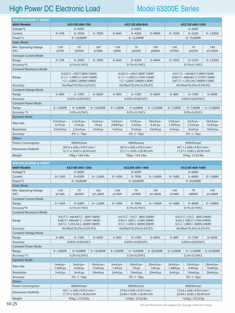
10-25 All specifications are subject to change without notice. All specifications are subject to change without notice.
High Power DC Electronic Load Model 63200E SeriesSPECIFICATIONS-7 (600V)600V Models 63210E-600-700 63212E-600-840 63215E-600-1050Voltage*2 0~600V 0~600V 0~600VCurrent 0~70A 0~350A 0~700A 0~84A 0~420A 0~840A 0~105A 0~525A 0~1,050APower*3 0~10,000W 0~12,000W 0~15,000WStatic Mode
Min. Operating Voltage(DC)
1.4V@70A
7V@350A
14V@700A
1.4V@84A
7V@420A
14V@840A
1.4V@105A
7V@525A
14V@1,050A
Constant Current ModeRange 0~70A 0~350A 0~700A 0~84A 0~420A 0~840A 0~105A 0~525A 0~1,050AAccuracy*4 0.1%+0.1%F.S. 0.1%+0.1%F.S. 0.1%+0.1%F.S.Constant Resistance Mode
Range0.025Ω~250Ω(80V/10kW)0.1Ω~1,000Ω(150V/10kW)1Ω~2,000Ω(600V/10kW)
0.025Ω~250Ω(80V/12kW)0.1Ω~1,000Ω(150V/12kW)1Ω~2,000Ω(600V/12kW)
0.017Ω~166.667Ω(80V/15kW)0.067Ω~666.667Ω(150V/15kW)0.67Ω~1,333.34Ω(600V/15kW)
Accuracy Vin/Rset*(0.2%)+0.2% IF.S. Vin/Rset*(0.2%)+0.2% IF.S. Vin/Rset*(0.2%)+0.2% IF.S.Constant Voltage ModeRange 0~80V 0~150V 0~600V 0~80V 0~150V 0~600V 0~80V 0~150V 0~600VAccuracy 0.05%+0.025%F.S. 0.05%+0.025%F.S. 0.05%+0.025%F.S.Constant Power ModeRange 0~1,000W 0~5,000W 0~10,000W 0~1,200W 0~6,000W 0~12,000W 0~1,500W 0~7,500W 0~15,000WAccuracy *5 0.2%+0.2%F.S. 0.2%+0.2%F.S. 0.2%+0.2%F.S.Dynamic Mode
Slew rate 0.5mA/µs~0.7A/µs
2.5mA/µs~3.5A/µs
5mA/µs~7A/µs
1mA/µs~0.84A/µs
5mA/µs~4.2A/µs
10mA/µs~8.4A/µs
1mA/µs~1.05A/µs
5mA/µs~5.25A/µs
10mA/µs~10.5A/µs
Resolution 0.5mA/µs 2.5mA/µs 5mA/µs 1mA/µs 5mA/µs 10mA/µs 1mA/µs 5mA/µs 10mA/µsAccuracy 5% ± 10µs 5% ± 10µs 5% ± 10µsOthersPower Consumption 400VA(max) 400VA(max) 600VA(max)
Dimension (HxWxD) 307.6 x 428 x 670.5 mm /12.11 x 16.85 x 26.40 inch
307.6 x 428 x 670.5 mm /12.11 x 16.85 x 26.40 inch
441.1 x 428 x 670.5 mm /17.37 x 16.85 x 26.40 inch
Weight 70kg / 154.3 lbs 70kg / 154.3 lbs 97kg / 213.8 lbs
SPECIFICATIONS-8 (600V)600V Models 63218E-600-1260 63220E-600-1400 63224E-600-1680Voltage*2 0~600V 0~600V 0~600VCurrent 0~126A 0~630A 0~1,260A 0~140A 0~700A 0~1,400A 0~168A 0~840A 0~1,680APower*3 0~18,000W 0~20,000W 0~24,000WStatic Mode
Min. Operating Voltage(DC)
1.4V@126A
7V@630A
14V@1,260A
1.4V@140A
7V@700A
14V@1,400A
1.4V@168A
7V@840A
14V@1,680A
Constant Current ModeRange 0~126A 0~630A 0~1,260A 0~140A 0~700A 0~1,400A 0~168A 0~840A 0~1,680AAccuracy*4 0.1%+0.1%F.S. 0.1%+0.1%F.S. 0.1%+0.1%F.S.Constant Resistance Mode
Range0.017Ω-166.667Ω (80V/18kW)0.067Ω-666.667Ω (150V/18kW)0.67Ω-1,333.34Ω (600V/18kW)
0.013Ω-125Ω (80V/20kW)0.05Ω-500Ω (150V/20kW)0.5Ω-1,000Ω (600V/20kW)
0.013Ω-125Ω (80V/24kW)0.05Ω-500Ω (150V/24kW)0.5Ω-1,000Ω (600V/24kW)
Accuracy Vin/Rset*(0.2%)+0.2% IF.S. Vin/Rset*(0.2%)+0.2% IF.S. Vin/Rset*(0.2%)+0.2% IF.S.Constant Voltage ModeRange 0~80V 0~150V 0~600V 0~80V 0~150V 0~600V 0~80V 0~150V 0~600VAccuracy 0.05%+0.025%F.S. 0.05%+0.025%F.S. 0.05%+0.025%F.S.Constant Power ModeRange 0~1,800W 0~9,000W 0~18,000W 0~2,000W 0~10,000W 0~20,000W 0~2,400W 0~12,000W 0~24,000WAccuracy *5 0.2%+0.2%F.S. 0.2%+0.2%F.S. 0.2%+0.2%F.S.Dynamic Mode
Slew rate 1mA/µs~1.26A/µs
5mA/µs~6.3A/µs
10mA/µs~12.6A/µs
2mA/µs~1.4A/µs
10mA/µs~7A/µs
20mA/µs~14A/µs
2mA/µs~1.68A/µs
10mA/µs~8.4A/µs
20mA/µs~16.8A/µs
Resolution 1mA/µs 5mA/µs 10mA/µs 2mA/µs 10mA/µs 20mA/µs 2mA/µs 10mA/µs 20mA/µsAccuracy 5% ± 10µs 5% ± 10µs 5% ± 10µsOthersPower Consumption 600VA(max) 800VA(max) 800VA(max)
Dimension (HxWxD) 441.1 x 428 x 670.5 mm /17.37 x 16.85 x 26.40 inch
574.6 x 428 x 670.5 mm /22.64 x 16.85 x 26.40 inch
574.6 x 428 x 670.5 mm /22.64 x 16.85 x 26.40 inch
Weight 97kg / 213.8 lbs 125kg / 275.6 lbs 125kg / 275.6 lbs
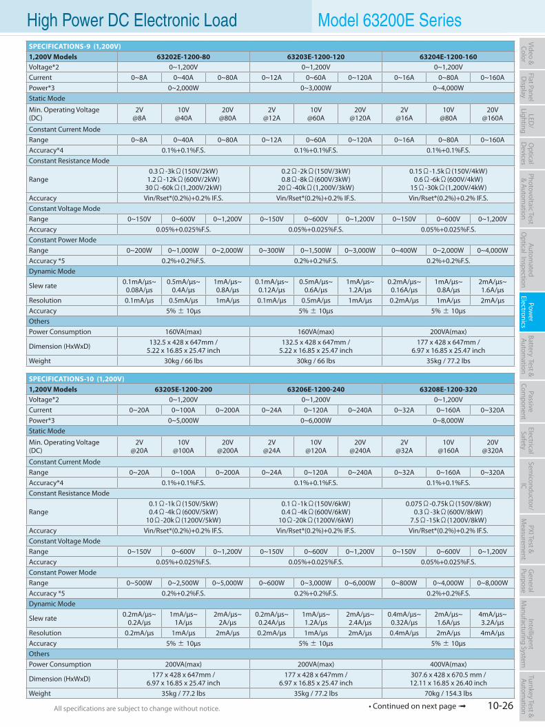
10-26All specifications are subject to change without notice. All specifications are subject to change without notice.
Flat PanelD
isplayPow
er Electronics
Electrical Safety
General
PurposePassive
Component
Semiconductor/
ICBattery Test & Autom
ationAutom
atedO
ptical Inspection Photovoltaic Test
& Automation
PXI Test &
Measurem
ent Video & Color
LED/
LightingO
ptical D
evicesIntelligent
Manufacturing System
Turnkey Test & Autom
ation High Power DC Electronic Load Model 63200E SeriesSPECIFICATIONS-9 (1,200V)1,200V Models 63202E-1200-80 63203E-1200-120 63204E-1200-160Voltage*2 0~1,200V 0~1,200V 0~1,200VCurrent 0~8A 0~40A 0~80A 0~12A 0~60A 0~120A 0~16A 0~80A 0~160APower*3 0~2,000W 0~3,000W 0~4,000WStatic Mode
Min. Operating Voltage(DC)
2V@8A
10V@40A
20V@80A
2V@12A
10V@60A
20V@120A
2V@16A
10V@80A
20V@160A
Constant Current ModeRange 0~8A 0~40A 0~80A 0~12A 0~60A 0~120A 0~16A 0~80A 0~160AAccuracy*4 0.1%+0.1%F.S. 0.1%+0.1%F.S. 0.1%+0.1%F.S.Constant Resistance Mode
Range0.3Ω-3kΩ(150V/2kW)
1.2Ω-12kΩ(600V/2kW)30Ω-60kΩ(1,200V/2kW)
0.2Ω-2kΩ(150V/3kW)0.8Ω-8kΩ(600V/3kW)
20Ω-40kΩ(1,200V/3kW)
0.15Ω-1.5kΩ(150V/4kW)0.6Ω-6kΩ(600V/4kW)
15Ω-30kΩ(1,200V/4kW)Accuracy Vin/Rset*(0.2%)+0.2% IF.S. Vin/Rset*(0.2%)+0.2% IF.S. Vin/Rset*(0.2%)+0.2% IF.S.Constant Voltage ModeRange 0~150V 0~600V 0~1,200V 0~150V 0~600V 0~1,200V 0~150V 0~600V 0~1,200VAccuracy 0.05%+0.025%F.S. 0.05%+0.025%F.S. 0.05%+0.025%F.S.Constant Power ModeRange 0~200W 0~1,000W 0~2,000W 0~300W 0~1,500W 0~3,000W 0~400W 0~2,000W 0~4,000WAccuracy *5 0.2%+0.2%F.S. 0.2%+0.2%F.S. 0.2%+0.2%F.S.Dynamic Mode
Slew rate 0.1mA/µs~0.08A/µs
0.5mA/µs~0.4A/µs
1mA/µs~0.8A/µs
0.1mA/µs~0.12A/µs
0.5mA/µs~0.6A/µs
1mA/µs~1.2A/µs
0.2mA/µs~0.16A/µs
1mA/µs~0.8A/µs
2mA/µs~1.6A/µs
Resolution 0.1mA/µs 0.5mA/µs 1mA/µs 0.1mA/µs 0.5mA/µs 1mA/µs 0.2mA/µs 1mA/µs 2mA/µsAccuracy 5% ± 10µs 5% ± 10µs 5% ± 10µsOthersPower Consumption 160VA(max) 160VA(max) 200VA(max)
Dimension (HxWxD) 132.5 x 428 x 647mm / 5.22 x 16.85 x 25.47 inch
132.5 x 428 x 647mm / 5.22 x 16.85 x 25.47 inch
177 x 428 x 647mm /6.97 x 16.85 x 25.47 inch
Weight 30kg / 66 lbs 30kg / 66 lbs 35kg / 77.2 lbs
SPECIFICATIONS-10 (1,200V)1,200V Models 63205E-1200-200 63206E-1200-240 63208E-1200-320Voltage*2 0~1,200V 0~1,200V 0~1,200VCurrent 0~20A 0~100A 0~200A 0~24A 0~120A 0~240A 0~32A 0~160A 0~320APower*3 0~5,000W 0~6,000W 0~8,000WStatic Mode
Min. Operating Voltage(DC)
2V@20A
10V@100A
20V@200A
2V@24A
10V@120A
20V@240A
2V@32A
10V@160A
20V@320A
Constant Current ModeRange 0~20A 0~100A 0~200A 0~24A 0~120A 0~240A 0~32A 0~160A 0~320AAccuracy*4 0.1%+0.1%F.S. 0.1%+0.1%F.S. 0.1%+0.1%F.S.Constant Resistance Mode
Range0.1Ω-1kΩ(150V/5kW)0.4Ω-4kΩ(600V/5kW)
10Ω-20kΩ(1200V/5kW)
0.1Ω-1kΩ(150V/6kW)0.4Ω-4kΩ(600V/6kW)
10Ω-20kΩ(1200V/6kW)
0.075Ω-0.75kΩ(150V/8kW)0.3Ω-3kΩ(600V/8kW)
7.5Ω-15kΩ(1200V/8kW)Accuracy Vin/Rset*(0.2%)+0.2% IF.S. Vin/Rset*(0.2%)+0.2% IF.S. Vin/Rset*(0.2%)+0.2% IF.S.Constant Voltage ModeRange 0~150V 0~600V 0~1,200V 0~150V 0~600V 0~1,200V 0~150V 0~600V 0~1,200VAccuracy 0.05%+0.025%F.S. 0.05%+0.025%F.S. 0.05%+0.025%F.S.Constant Power ModeRange 0~500W 0~2,500W 0~5,000W 0~600W 0~3,000W 0~6,000W 0~800W 0~4,000W 0~8,000WAccuracy *5 0.2%+0.2%F.S. 0.2%+0.2%F.S. 0.2%+0.2%F.S.Dynamic Mode
Slew rate 0.2mA/µs~0.2A/µs
1mA/µs~1A/µs
2mA/µs~2A/µs
0.2mA/µs~0.24A/µs
1mA/µs~1.2A/µs
2mA/µs~2.4A/µs
0.4mA/µs~0.32A/µs
2mA/µs~1.6A/µs
4mA/µs~3.2A/µs
Resolution 0.2mA/µs 1mA/µs 2mA/µs 0.2mA/µs 1mA/µs 2mA/µs 0.4mA/µs 2mA/µs 4mA/µsAccuracy 5% ± 10µs 5% ± 10µs 5% ± 10µsOthersPower Consumption 200VA(max) 200VA(max) 400VA(max)
Dimension (HxWxD) 177 x 428 x 647mm /6.97 x 16.85 x 25.47 inch
177 x 428 x 647mm /6.97 x 16.85 x 25.47 inch
307.6 x 428 x 670.5 mm /12.11 x 16.85 x 26.40 inch
Weight 35kg / 77.2 lbs 35kg / 77.2 lbs 70kg / 154.3 lbs
• Continued on next page
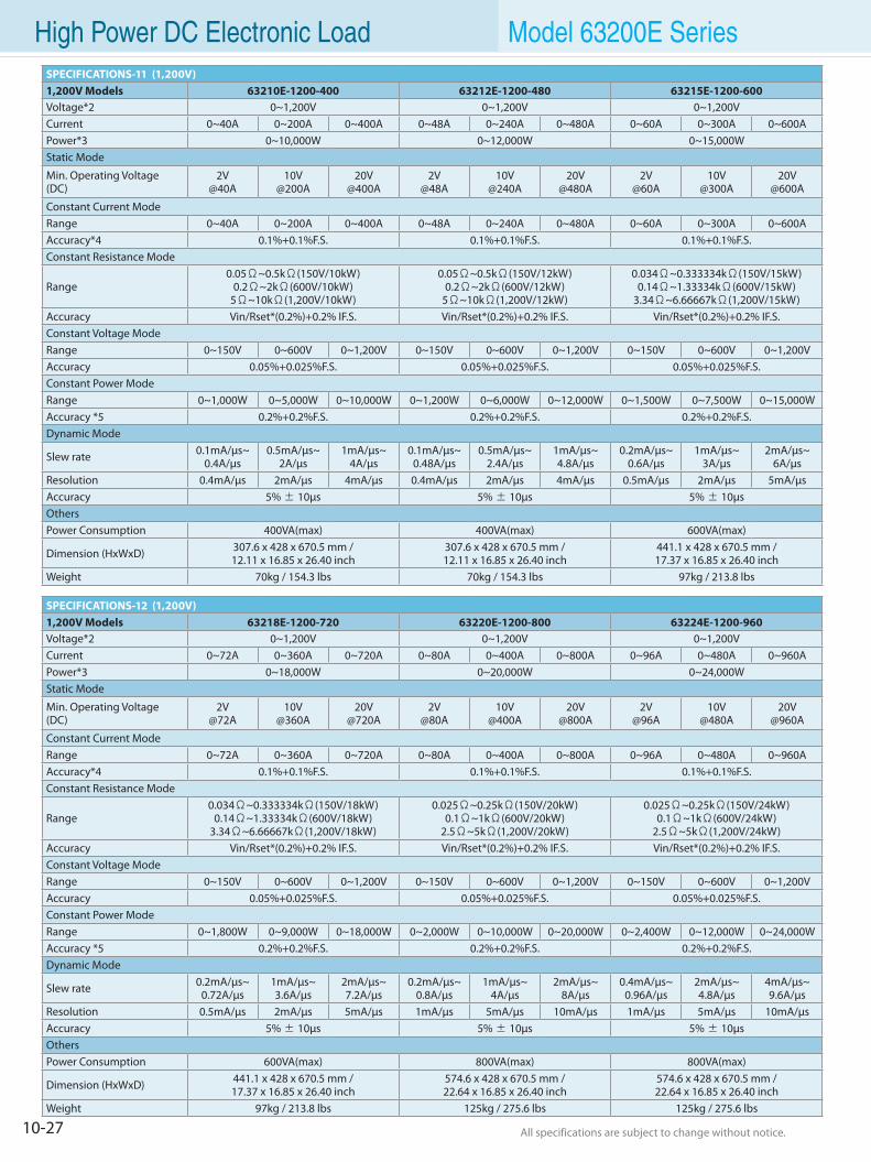
10-27 All specifications are subject to change without notice. All specifications are subject to change without notice.
High Power DC Electronic Load Model 63200E SeriesSPECIFICATIONS-11 (1,200V)1,200V Models 63210E-1200-400 63212E-1200-480 63215E-1200-600Voltage*2 0~1,200V 0~1,200V 0~1,200VCurrent 0~40A 0~200A 0~400A 0~48A 0~240A 0~480A 0~60A 0~300A 0~600APower*3 0~10,000W 0~12,000W 0~15,000WStatic Mode
Min. Operating Voltage(DC)
2V@40A
10V@200A
20V@400A
2V@48A
10V@240A
20V@480A
2V@60A
10V@300A
20V@600A
Constant Current ModeRange 0~40A 0~200A 0~400A 0~48A 0~240A 0~480A 0~60A 0~300A 0~600AAccuracy*4 0.1%+0.1%F.S. 0.1%+0.1%F.S. 0.1%+0.1%F.S.Constant Resistance Mode
Range0.05Ω~0.5kΩ(150V/10kW)
0.2Ω~2kΩ(600V/10kW)5Ω~10kΩ(1,200V/10kW)
0.05Ω~0.5kΩ(150V/12kW)0.2Ω~2kΩ(600V/12kW)
5Ω~10kΩ(1,200V/12kW)
0.034Ω~0.333334kΩ(150V/15kW)0.14Ω~1.33334kΩ(600V/15kW)
3.34Ω~6.66667kΩ(1,200V/15kW)Accuracy Vin/Rset*(0.2%)+0.2% IF.S. Vin/Rset*(0.2%)+0.2% IF.S. Vin/Rset*(0.2%)+0.2% IF.S.Constant Voltage ModeRange 0~150V 0~600V 0~1,200V 0~150V 0~600V 0~1,200V 0~150V 0~600V 0~1,200VAccuracy 0.05%+0.025%F.S. 0.05%+0.025%F.S. 0.05%+0.025%F.S.Constant Power ModeRange 0~1,000W 0~5,000W 0~10,000W 0~1,200W 0~6,000W 0~12,000W 0~1,500W 0~7,500W 0~15,000WAccuracy *5 0.2%+0.2%F.S. 0.2%+0.2%F.S. 0.2%+0.2%F.S.Dynamic Mode
Slew rate 0.1mA/µs~0.4A/µs
0.5mA/µs~2A/µs
1mA/µs~4A/µs
0.1mA/µs~0.48A/µs
0.5mA/µs~2.4A/µs
1mA/µs~4.8A/µs
0.2mA/µs~0.6A/µs
1mA/µs~3A/µs
2mA/µs~6A/µs
Resolution 0.4mA/µs 2mA/µs 4mA/µs 0.4mA/µs 2mA/µs 4mA/µs 0.5mA/µs 2mA/µs 5mA/µsAccuracy 5% ± 10µs 5% ± 10µs 5% ± 10µsOthersPower Consumption 400VA(max) 400VA(max) 600VA(max)
Dimension (HxWxD) 307.6 x 428 x 670.5 mm /12.11 x 16.85 x 26.40 inch
307.6 x 428 x 670.5 mm /12.11 x 16.85 x 26.40 inch
441.1 x 428 x 670.5 mm /17.37 x 16.85 x 26.40 inch
Weight 70kg / 154.3 lbs 70kg / 154.3 lbs 97kg / 213.8 lbs
SPECIFICATIONS-12 (1,200V)1,200V Models 63218E-1200-720 63220E-1200-800 63224E-1200-960Voltage*2 0~1,200V 0~1,200V 0~1,200VCurrent 0~72A 0~360A 0~720A 0~80A 0~400A 0~800A 0~96A 0~480A 0~960APower*3 0~18,000W 0~20,000W 0~24,000WStatic Mode
Min. Operating Voltage(DC)
2V@72A
10V@360A
20V@720A
2V@80A
10V@400A
20V@800A
2V@96A
10V@480A
20V@960A
Constant Current ModeRange 0~72A 0~360A 0~720A 0~80A 0~400A 0~800A 0~96A 0~480A 0~960AAccuracy*4 0.1%+0.1%F.S. 0.1%+0.1%F.S. 0.1%+0.1%F.S.Constant Resistance Mode
Range0.034Ω~0.333334kΩ(150V/18kW)
0.14Ω~1.33334kΩ(600V/18kW)3.34Ω~6.66667kΩ(1,200V/18kW)
0.025Ω~0.25kΩ(150V/20kW)0.1Ω~1kΩ(600V/20kW)
2.5Ω~5kΩ(1,200V/20kW)
0.025Ω~0.25kΩ(150V/24kW)0.1Ω~1kΩ(600V/24kW)
2.5Ω~5kΩ(1,200V/24kW)Accuracy Vin/Rset*(0.2%)+0.2% IF.S. Vin/Rset*(0.2%)+0.2% IF.S. Vin/Rset*(0.2%)+0.2% IF.S.Constant Voltage ModeRange 0~150V 0~600V 0~1,200V 0~150V 0~600V 0~1,200V 0~150V 0~600V 0~1,200VAccuracy 0.05%+0.025%F.S. 0.05%+0.025%F.S. 0.05%+0.025%F.S.Constant Power ModeRange 0~1,800W 0~9,000W 0~18,000W 0~2,000W 0~10,000W 0~20,000W 0~2,400W 0~12,000W 0~24,000WAccuracy *5 0.2%+0.2%F.S. 0.2%+0.2%F.S. 0.2%+0.2%F.S.Dynamic Mode
Slew rate 0.2mA/µs~0.72A/µs
1mA/µs~3.6A/µs
2mA/µs~7.2A/µs
0.2mA/µs~0.8A/µs
1mA/µs~4A/µs
2mA/µs~8A/µs
0.4mA/µs~0.96A/µs
2mA/µs~4.8A/µs
4mA/µs~9.6A/µs
Resolution 0.5mA/µs 2mA/µs 5mA/µs 1mA/µs 5mA/µs 10mA/µs 1mA/µs 5mA/µs 10mA/µsAccuracy 5% ± 10µs 5% ± 10µs 5% ± 10µsOthersPower Consumption 600VA(max) 800VA(max) 800VA(max)
Dimension (HxWxD) 441.1 x 428 x 670.5 mm /17.37 x 16.85 x 26.40 inch
574.6 x 428 x 670.5 mm /22.64 x 16.85 x 26.40 inch
574.6 x 428 x 670.5 mm /22.64 x 16.85 x 26.40 inch
Weight 97kg / 213.8 lbs 125kg / 275.6 lbs 125kg / 275.6 lbs
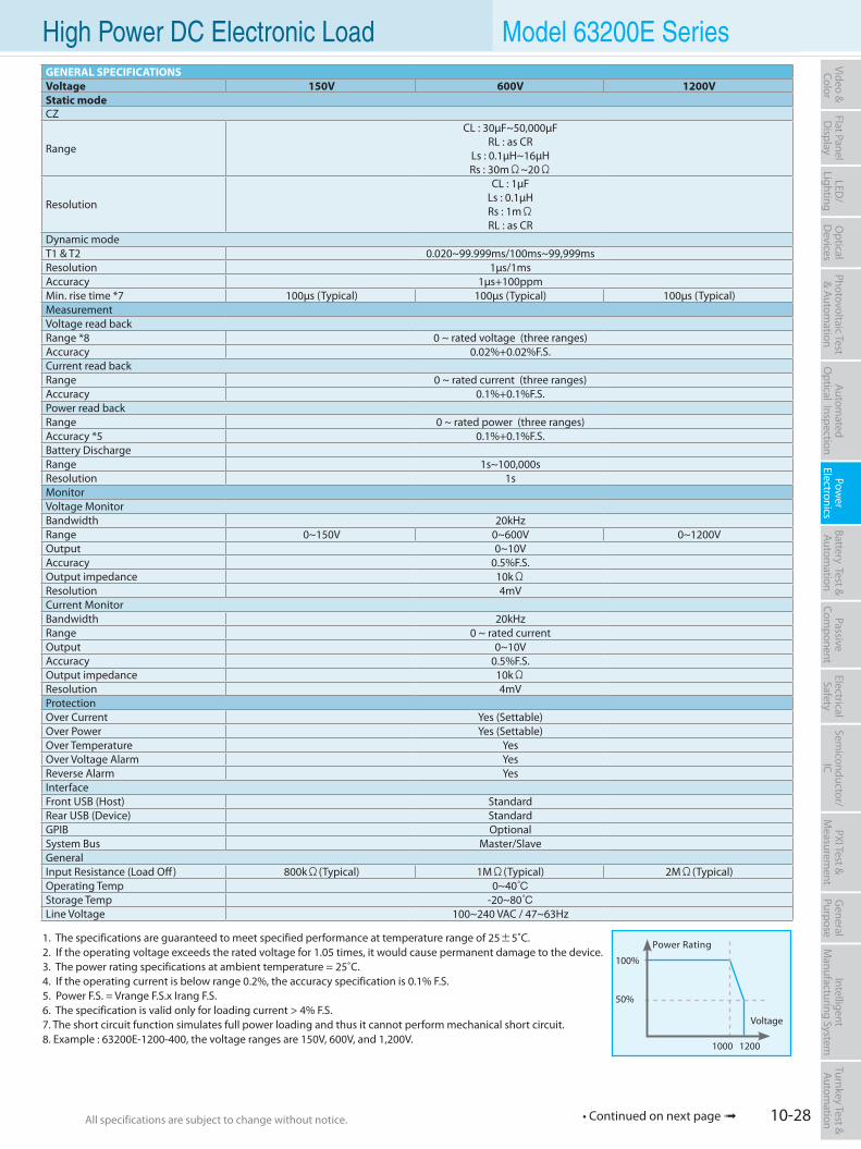
10-28All specifications are subject to change without notice. All specifications are subject to change without notice.
Flat PanelD
isplayPow
er Electronics
Electrical Safety
General
PurposePassive
Component
Semiconductor/
ICBattery Test & Autom
ationAutom
atedO
ptical Inspection Photovoltaic Test
& Automation
PXI Test &
Measurem
ent Video & Color
LED/
LightingO
ptical D
evicesIntelligent
Manufacturing System
Turnkey Test & Autom
ation High Power DC Electronic Load Model 63200E Series
1. The specifications are guaranteed to meet specified performance at temperature range of 25±5˚C.2. If the operating voltage exceeds the rated voltage for 1.05 times, it would cause permanent damage to the device.3. The power rating specifications at ambient temperature = 25˚C.4. If the operating current is below range 0.2%, the accuracy specification is 0.1% F.S.5. Power F.S. = Vrange F.S.x Irang F.S.6. The specification is valid only for loading current > 4% F.S.7. The short circuit function simulates full power loading and thus it cannot perform mechanical short circuit.8. Example : 63200E-1200-400, the voltage ranges are 150V, 600V, and 1,200V.
Power Rating
100%
50%
Voltage
1000 1200
GENERAL SPECIFICATIONSVoltage 150V 600V 1200VStatic modeCZ
Range
CL : 30µF~50,000µF RL : as CR
Ls : 0.1µH~16µH Rs : 30mΩ~20Ω
Resolution
CL : 1µFLs : 0.1µHRs : 1mΩRL : as CR
Dynamic modeT1 & T2 0.020~99.999ms/100ms~99,999msResolution 1µs/1msAccuracy 1µs+100ppmMin. rise time *7 100µs (Typical) 100µs (Typical) 100µs (Typical)Measurement Voltage read backRange *8 0 ~ rated voltage (three ranges)Accuracy 0.02%+0.02%F.S.Current read backRange 0 ~ rated current (three ranges)Accuracy 0.1%+0.1%F.S.Power read backRange 0 ~ rated power (three ranges)Accuracy *5 0.1%+0.1%F.S.Battery Discharge Range 1s~100,000sResolution 1sMonitorVoltage MonitorBandwidth 20kHzRange 0~150V 0~600V 0~1200VOutput 0~10VAccuracy 0.5%F.S.Output impedance 10kΩResolution 4mVCurrent MonitorBandwidth 20kHzRange 0 ~ rated currentOutput 0~10VAccuracy 0.5%F.S.Output impedance 10kΩResolution 4mVProtectionOver Current Yes (Settable)Over Power Yes (Settable)Over Temperature YesOver Voltage Alarm YesReverse Alarm YesInterfaceFront USB (Host) StandardRear USB (Device) StandardGPIB OptionalSystem Bus Master/SlaveGeneralInput Resistance (Load Off) 800kΩ(Typical) 1MΩ(Typical) 2MΩ(Typical)Operating Temp 0~40Storage Temp -20~80Line Voltage 100~240 VAC / 47~63Hz
• Continued on next page
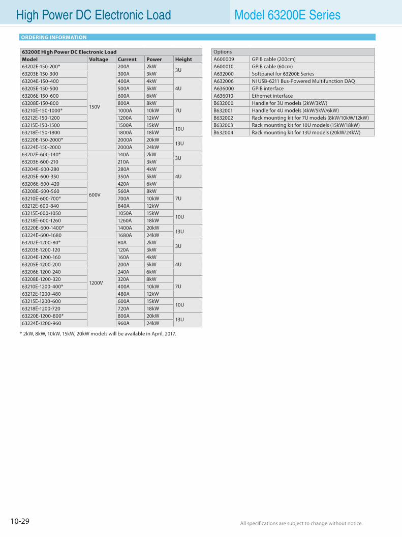
10-29 All specifications are subject to change without notice. All specifications are subject to change without notice.
High Power DC Electronic Load Model 63200E Series
ORDERING INFORMATION
OptionsA600009 GPIB cable (200cm)A600010 GPIB cable (60cm)A632000 Softpanel for 63200E SeriesA632006 NI USB-6211 Bus-Powered Multifunction DAQA636000 GPIB interfaceA636010 Ethernet interfaceB632000 Handle for 3U models (2kW/3kW)B632001 Handle for 4U models (4kW/5kW/6kW)B632002 Rack mounting kit for 7U models (8kW/10kW/12kW)B632003 Rack mounting kit for 10U models (15kW/18kW)B632004 Rack mounting kit for 13U models (20kW/24kW)
* 2kW, 8kW, 10kW, 15kW, 20kW models will be available in April, 2017.
63200E High Power DC Electronic Load Model Voltage Current Power Height63202E-150-200*
150V
200A 2kW3U
63203E-150-300 300A 3kW63204E-150-400 400A 4kW
4U63205E-150-500 500A 5kW63206E-150-600 600A 6kW63208E-150-800 800A 8kW
7U63210E-150-1000* 1000A 10kW63212E-150-1200 1200A 12kW63215E-150-1500 1500A 15kW
10U63218E-150-1800 1800A 18kW63220E-150-2000* 2000A 20kW
13U63224E-150-2000 2000A 24kW63202E-600-140*
600V
140A 2kW3U
63203E-600-210 210A 3kW63204E-600-280 280A 4kW
4U63205E-600-350 350A 5kW63206E-600-420 420A 6kW63208E-600-560 560A 8kW
7U63210E-600-700* 700A 10kW63212E-600-840 840A 12kW63215E-600-1050 1050A 15kW
10U63218E-600-1260 1260A 18kW63220E-600-1400* 1400A 20kW
13U63224E-600-1680 1680A 24kW63202E-1200-80*
1200V
80A 2kW3U
63203E-1200-120 120A 3kW63204E-1200-160 160A 4kW
4U63205E-1200-200 200A 5kW63206E-1200-240 240A 6kW63208E-1200-320 320A 8kW
7U63210E-1200-400* 400A 10kW63212E-1200-480 480A 12kW63215E-1200-600 600A 15kW
10U63218E-1200-720 720A 18kW63220E-1200-800* 800A 20kW
13U63224E-1200-960 960A 24kW
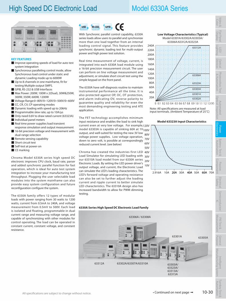
10-30All specifications are subject to change without notice. All specifications are subject to change without notice.
Flat PanelD
isplayPow
er Electronics
Electrical Safety
General
PurposePassive
Component
Semiconductor/
ICBattery Test & Autom
ationAutom
atedO
ptical Inspection Photovoltaic Test
& Automation
PXI Test &
Measurem
ent Video & Color
LED/
LightingO
ptical D
evicesIntelligent
Manufacturing System
Turnkey Test & Autom
ation
With Synchronic parallel control capability, 6330A series loads allow users to parallel and synchronize more than one load together from an internal loading control signal. This feature provides synchronic dynamic loading test for multi-output power and high power test solution.
Real time measurement of voltage, current, is integrated into each 6330A load module using a 16-bit precision measurement circuit. The user can perform on line voltage measurement and adjustment, or simulate short circuit test using the simple keypad on the front panel.
The 6330A have self-diagnosis routine to maintain instrumental performance all the time. It is also protected against OP, OC, OT protection, and alarm indicating OV, reverse polarity to guarantee quality and reliability for even the most demanding engineering testing and ATE application.
The FET technology accomplishes minimum input resistance and enables the load to sink high current even at very low voltage. For example, model 63303A is capable of sinking 60A at 1V output, and well-suited for testing the new 3V low voltage power supplies. Low voltage operation, down to zero volt, is possible at correspondingly reduced current level. (see below)
Chroma has created the industries first LED Load Simulator for simulating LED loading with our 63310A load model from our 6330A series Electronic Loads. By setting the LED power driver's output voltage, and current, the Electronic Load can simulate the LED's loading characteristics. The LED's forward voltage and operating resistance can also be set to further adjust the loading current and ripple current to better simulate LED characteristics. The 63310A design also has increased bandwidth to allow for PWM dimming testing.
KEY FEATURES Improve operating speeds of load for auto test system integration Synchronous paralleling control mode, allow Synchronous load control under static and dynamic Loading mode up to 6000W Up to 8 channels in one mainframe, fit for testing Multiple output SMPS. GPIB, RS-232 & USB Interfaces Max Power: 200W, 100W x 2(Dual), 30W&250W, 300W, 350W, 600W, 1200W Voltage Range:0~80V/0~120V/0~500V/0~600V CC, CR, CV, CP operating modes Dynamic loading with speed up to 20kHz Programmable slew rate, up to 10A/µs Only need 0.6V to draw rated current (63323A) Individual panel meters Real time power supplies load transient response simulation and output measurement 16-bit precision voltage and measurement with dual-range selection Remote sensing capability Short circuit test Self-test at power-on CE marking
Chroma Model 6330A series high speed DC electronic improves CPU clock, baud rate, parser and added synchronic parallel function for fast operation, which is ideal for auto test system integration to increase your manufacturing test throughput. Plugging the user selectable load modules into the system mainframe can also provide easy system configuration and future reconfiguration configure the system.
The 6330A family offers 12 types of modular loads with power ranging from 30 watts to 1200 watts, current from 0.5mA to 240A, and voltage measurement from 0.5mV to 500V. Each load is isolated and floating, programmable in dual current range and measuring voltage range, and capable of synchronizing with other modules for control operating. The load can be operated in constant current, constant voltage, and constant resistance.
High Speed DC Electronic Load Model 6330A Series
Low Voltage Characteristics (Typical)Model 63301A/63302A/63303A/
63306A/63312A/63323A240A220A200A180A
160A
140A120A100A
80A60A
40A
0 0.1 0.2 0.3 0.4 0.5 0.6 0.7 0.8 0.9 1.0 1.1 1.2 1.3 (V)
63312A
63306A
63303A
63301A
63302A
Note: All specifications are measured at loadinput terminals. (Ambient Temperature of 25˚C)
20A
6330A Series High Speed DC Electronic Load Family
63306A / 63308A
63302A/63307A/63310A
63301A 63305A
63312A 63303A/63323A/63313A/63315A
63323A
Model 63323A Input Characteristics
80V100V120V
70V60V50V40V30V20V10V
2.916A 10A 20A 40A 60A30A 50A 70A20A 40A 60A
• Continued on next page
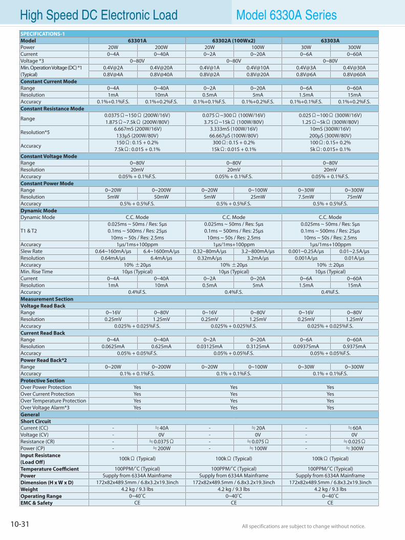
10-31 All specifications are subject to change without notice. All specifications are subject to change without notice.
High Speed DC Electronic Load Model 6330A SeriesSPECIFICATIONS-1Model 63301A 63302A (100Wx2) 63303APower 20W 200W 20W 100W 30W 300WCurrent 0~4A 0~40A 0~2A 0~20A 0~6A 0~60AVoltage *3 0~80V 0~80V 0~80VMin. Operation Voltage (DC) *1(Typical)
0.4V@2A 0.4V@20A 0.4V@1A 0.4V@10A 0.4V@3A [email protected]@4A 0.8V@40A 0.8V@2A 0.8V@20A 0.8V@6A 0.8V@60A
Constant Current ModeRange 0~4A 0~40A 0~2A 0~20A 0~6A 0~60AResolution 1mA 10mA 0.5mA 5mA 1.5mA 15mAAccuracy 0.1%+0.1%F.S. 0.1%+0.2%F.S. 0.1%+0.1%F.S. 0.1%+0.2%F.S. 0.1%+0.1%F.S. 0.1%+0.2%F.S.Constant Resistance Mode
Range0.0375Ω~150Ω (200W/16V)1.875Ω~7.5kΩ (200W/80V)
0.075Ω~300Ω (100W/16V)3.75Ω~15kΩ (100W/80V)
0.025Ω~100Ω (300W/16V)1.25Ω~5kΩ (300W/80V)
Resolution*5 6.667mS (200W/16V)
133µS (200W/80V)3.333mS (100W/16V)66.667µS (100W/80V)
10mS (300W/16V)200µS (300W/80V)
Accuracy150Ω: 0.1S + 0.2%
7.5kΩ: 0.01S + 0.1% 300Ω: 0.1S + 0.2%
15kΩ: 0.01S + 0.1%100Ω: 0.1S+ 0.2%5kΩ: 0.01S+ 0.1%
Constant Voltage ModeRange 0~80V 0~80V 0~80VResolution 20mV 20mV 20mVAccuracy 0.05% + 0.1%F.S. 0.05% + 0.1%F.S. 0.05% + 0.1%F.S.Constant Power ModeRange 0~20W 0~200W 0~20W 0~100W 0~30W 0~300WResolution 5mW 50mW 5mW 25mW 7.5mW 75mWAccuracy 0.5% + 0.5%F.S. 0.5% + 0.5%F.S. 0.5% + 0.5%F.S.Dynamic ModeDynamic Mode C.C. Mode C.C. Mode C.C. Mode
T1 & T20.025ms ~ 50ms / Res: 5µs0.1ms ~ 500ms / Res: 25µs
10ms ~ 50s / Res: 2.5ms
0.025ms ~ 50ms / Res: 5µs0.1ms ~ 500ms / Res: 25µs
10ms ~ 50s / Res: 2.5ms
0.025ms ~ 50ms / Res: 5µs0.1ms ~ 500ms / Res: 25µs
10ms ~ 50s / Res: 2.5msAccuracy 1µs/1ms+100ppm 1µs/1ms+100ppm 1µs/1ms+100ppmSlew Rate 0.64~160mA/µs 6.4~1600mA/µs 0.32~80mA/µs 3.2~800mA/µs 0.001~0.25A/µs 0.01~2.5A/µsResolution 0.64mA/µs 6.4mA/µs 0.32mA/µs 3.2mA/µs 0.001A/µs 0.01A/µsAccuracy 10% ±20µs 10% ±20µs 10% ±20µsMin. Rise Time 10µs (Typical) 10µs (Typical) 10µs (Typical)Current 0~4A 0~40A 0~2A 0~20A 0~6A 0~60AResolution 1mA 10mA 0.5mA 5mA 1.5mA 15mAAccuracy 0.4%F.S. 0.4%F.S. 0.4%F.S.Measurement SectionVoltage Read Back Range 0~16V 0~80V 0~16V 0~80V 0~16V 0~80VResolution 0.25mV 1.25mV 0.25mV 1.25mV 0.25mV 1.25mVAccuracy 0.025% + 0.025%F.S. 0.025% + 0.025%F.S. 0.025% + 0.025%F.S.Current Read BackRange 0~4A 0~40A 0~2A 0~20A 0~6A 0~60AResolution 0.0625mA 0.625mA 0.03125mA 0.3125mA 0.09375mA 0.9375mAAccuracy 0.05% + 0.05%F.S. 0.05% + 0.05%F.S. 0.05% + 0.05%F.S.Power Read Back*2Range 0~20W 0~200W 0~20W 0~100W 0~30W 0~300WAccuracy 0.1% + 0.1%F.S. 0.1% + 0.1%F.S. 0.1% + 0.1%F.S.Protective SectionOver Power Protection Yes Yes YesOver Current Protection Yes Yes YesOver Temperature Protection Yes Yes YesOver Voltage Alarm*3 Yes Yes YesGeneralShort CircuitCurrent (CC) - ≒40A - ≒20A - ≒60AVoltage (CV) - 0V - 0V - 0VResistance (CR) - ≒0.0375Ω - ≒0.075Ω - ≒0.025ΩPower (CP) - ≒200W - ≒100W - ≒300WInput Resistance(Load Off)
100kΩ (Typical) 100kΩ (Typical) 100kΩ (Typical)
Temperature Coefficient 100PPM/˚C (Typical) 100PPM/˚C (Typical) 100PPM/˚C (Typical)Power Supply from 6334A Mainframe Supply from 6334A Mainframe Supply from 6334A MainframeDimension (H x W x D) 172x82x489.5mm / 6.8x3.2x19.3inch 172x82x489.5mm / 6.8x3.2x19.3inch 172x82x489.5mm / 6.8x3.2x19.3inchWeight 4.2 kg / 9.3 lbs 4.2 kg / 9.3 lbs 4.2 kg / 9.3 lbsOperating Range 0~40˚C 0~40˚C 0~40˚CEMC & Safety CE CE CE
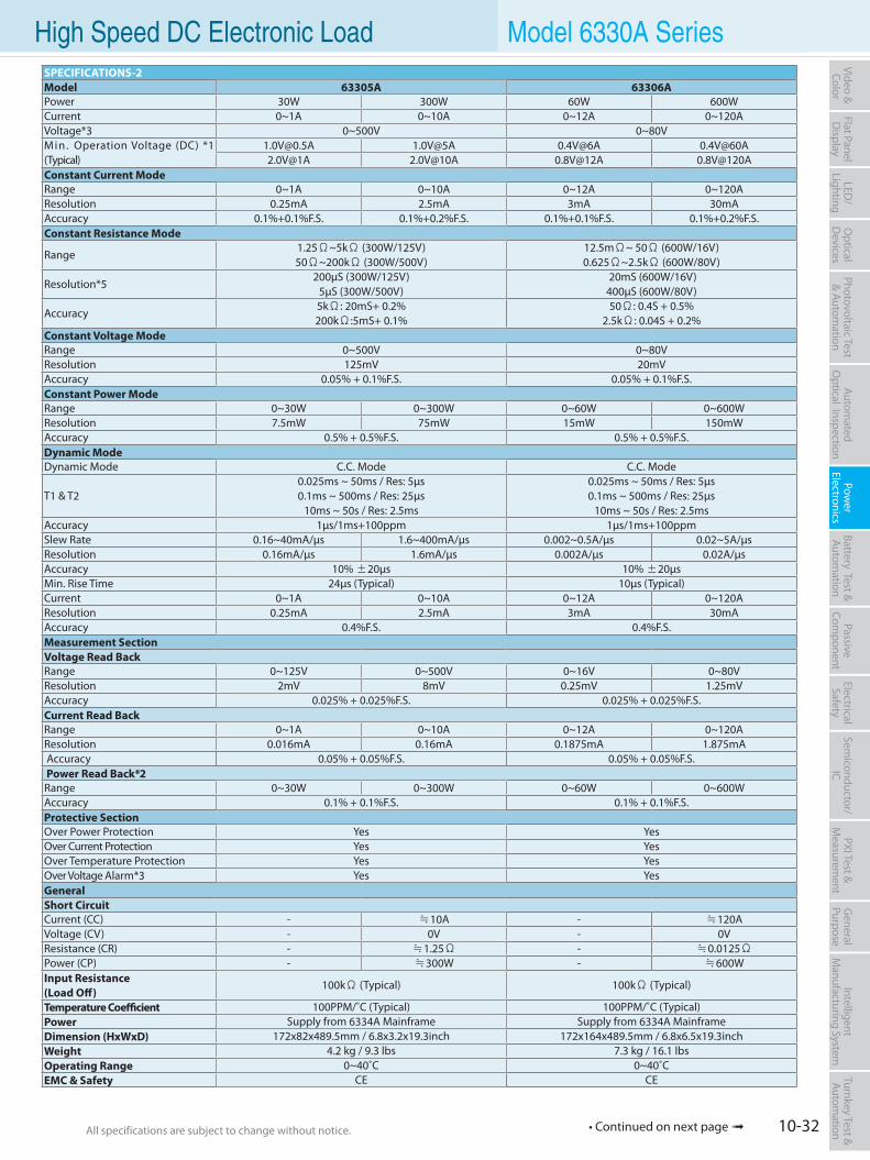
10-32All specifications are subject to change without notice. All specifications are subject to change without notice.
Flat PanelD
isplayPow
er Electronics
Electrical Safety
General
PurposePassive
Component
Semiconductor/
ICBattery Test & Autom
ationAutom
atedO
ptical Inspection Photovoltaic Test
& Automation
PXI Test &
Measurem
ent Video & Color
LED/
LightingO
ptical D
evicesIntelligent
Manufacturing System
Turnkey Test & Autom
ation
SPECIFICATIONS-2Model 63305A 63306APower 30W 300W 60W 600WCurrent 0~1A 0~10A 0~12A 0~120AVoltage*3 0~500V 0~80VMin. Operation Voltage (DC) *1 (Typical)
[email protected] 1.0V@5A 0.4V@6A [email protected]@1A 2.0V@10A 0.8V@12A 0.8V@120A
Constant Current ModeRange 0~1A 0~10A 0~12A 0~120AResolution 0.25mA 2.5mA 3mA 30mAAccuracy 0.1%+0.1%F.S. 0.1%+0.2%F.S. 0.1%+0.1%F.S. 0.1%+0.2%F.S.Constant Resistance Mode
Range1.25Ω~5kΩ (300W/125V)50Ω~200kΩ (300W/500V)
12.5mΩ~ 50Ω (600W/16V)0.625Ω~2.5kΩ (600W/80V)
Resolution*5200µS (300W/125V)
5µS (300W/500V) 20mS (600W/16V) 400µS (600W/80V)
Accuracy5kΩ: 20mS+ 0.2%200kΩ:5mS+ 0.1%
50Ω: 0.4S + 0.5%2.5kΩ: 0.04S + 0.2%
Constant Voltage ModeRange 0~500V 0~80VResolution 125mV 20mVAccuracy 0.05% + 0.1%F.S. 0.05% + 0.1%F.S.Constant Power ModeRange 0~30W 0~300W 0~60W 0~600WResolution 7.5mW 75mW 15mW 150mWAccuracy 0.5% + 0.5%F.S. 0.5% + 0.5%F.S.Dynamic ModeDynamic Mode C.C. Mode C.C. Mode
T1 & T20.025ms ~ 50ms / Res: 5µs0.1ms ~ 500ms / Res: 25µs
10ms ~ 50s / Res: 2.5ms
0.025ms ~ 50ms / Res: 5µs0.1ms ~ 500ms / Res: 25µs
10ms ~ 50s / Res: 2.5msAccuracy 1µs/1ms+100ppm 1µs/1ms+100ppmSlew Rate 0.16~40mA/µs 1.6~400mA/µs 0.002~0.5A/µs 0.02~5A/µsResolution 0.16mA/µs 1.6mA/µs 0.002A/µs 0.02A/µsAccuracy 10% ±20µs 10% ±20µsMin. Rise Time 24µs (Typical) 10µs (Typical)Current 0~1A 0~10A 0~12A 0~120AResolution 0.25mA 2.5mA 3mA 30mAAccuracy 0.4%F.S. 0.4%F.S.Measurement SectionVoltage Read Back Range 0~125V 0~500V 0~16V 0~80VResolution 2mV 8mV 0.25mV 1.25mVAccuracy 0.025% + 0.025%F.S. 0.025% + 0.025%F.S.Current Read BackRange 0~1A 0~10A 0~12A 0~120AResolution 0.016mA 0.16mA 0.1875mA 1.875mA Accuracy 0.05% + 0.05%F.S. 0.05% + 0.05%F.S. Power Read Back*2Range 0~30W 0~300W 0~60W 0~600WAccuracy 0.1% + 0.1%F.S. 0.1% + 0.1%F.S.Protective SectionOver Power Protection Yes YesOver Current Protection Yes YesOver Temperature Protection Yes YesOver Voltage Alarm*3 Yes YesGeneralShort CircuitCurrent (CC) - ≒10A - ≒120AVoltage (CV) - 0V - 0VResistance (CR) - ≒1.25Ω - ≒0.0125ΩPower (CP) - ≒300W - ≒600WInput Resistance(Load Off)
100kΩ (Typical) 100kΩ (Typical)
Temperature Coefficient 100PPM/˚C (Typical) 100PPM/˚C (Typical)Power Supply from 6334A Mainframe Supply from 6334A MainframeDimension (HxWxD) 172x82x489.5mm / 6.8x3.2x19.3inch 172x164x489.5mm / 6.8x6.5x19.3inchWeight 4.2 kg / 9.3 lbs 7.3 kg / 16.1 lbsOperating Range 0~40˚C 0~40˚CEMC & Safety CE CE
High Speed DC Electronic Load Model 6330A Series
• Continued on next page
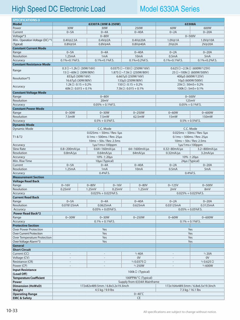
10-33 All specifications are subject to change without notice. All specifications are subject to change without notice.
High Speed DC Electronic Load Model 6330A SeriesSPECIFICATIONS-3Model 63307A (30W & 250W) 63308APower 30W 30W 250W 60W 600WCurrent 0~5A 0~4A 0~40A 0~2A 0~20AVoltage*3 0~80V 0~500VMin. Operation Voltage (DC) *1 (Typical)
[email protected] 0.4V@2A 0.4V@20A 1.0V@1A [email protected]@5A 0.8V@4A 0.8V@40A 2V@2A 2V@20A
Constant Current ModeRange 0~5A 0~4A 0~40A 0~2A 0~20AResolution 1.25mA 1mA 10mA 0.5mA 5mAAccuracy 0.1%+0.1%F.S. 0.1%+0.1%F.S. 0.1%+0.2%F.S. 0.1%+0.1%F.S. 0.1%+0.2%F.S.Constant Resistance Mode
Range0.3Ω~1.2kΩ (30W/16V) 15Ω~60kΩ (30W/80V)
0.0375Ω~150Ω (250W/16V)1.875Ω~7.5kΩ (250W/80V)
0.625Ω~2.5kΩ (600W/125V)25Ω~100kΩ (600W/500V)
Resolution*5833µS (30W/16V)
16.67µS (30W/80V)6.667µS (250W/16V)133µS (250W/80V)
400µS (600W/125V)10µS (600W/500V)
Accuracy1.2kΩ: 0.1S + 0.2%60kΩ: 0.01S + 0.1%
150Ω: 0.1S + 0.2%7.5kΩ: 0.01S + 0.1%
25kΩ: 50mS+ 0.2%100kΩ: 5mS+ 0.1%
Constant Voltage ModeRange 0~80V 0~500VResolution 20mV 125mVAccuracy 0.05% + 0.1%F.S. 0.05% + 0.1%F.S.Constant Power ModeRange 0~30W 0~30W 0~250W 0~60W 0~600WResolution 7.5mW 7.5mW 62.5mW 15mW 150mWAccuracy 0.5% + 0.5%F.S. 0.5% + 0.5%F.S.Dynamic ModeDynamic Mode C.C. Mode C.C. Mode
T1 & T20.025ms ~ 50ms / Res: 5µs0.1ms ~ 500ms / Res: 25µs
10ms ~ 50s / Res: 2.5ms
0.025ms ~ 50ms / Res: 5µs0.1ms ~ 500ms / Res: 25µs
10ms ~ 50s / Res: 2.5msAccuracy 1µs/1ms+100ppm 1µs/1ms+100ppmSlew Rate 0.8~200mA/µs 0.64~160mA/µs 64~1600mA/µs 0.32~80mA/µs 3.2~800mA/µsResolution 0.8mA/µs 0.64mA/µs 64mA/µs 0.32mA/µs 3.2mA/µsAccuracy 10% ±20µs 10% ±20µsMin. Rise Time 10µs (Typical) 24µs (Typical)Current 0~5A 0~4A 0~40A 0~2A 0~20AResolution 1.25mA 1mA 10mA 0.5mA 5mAAccuracy 0.4%F.S. 0.4%F.S.Measurement SectionVoltage Read Back Range 0~16V 0~80V 0~16V 0~80V 0~125V 0~500VResolution 0.25mV 1.25mV 0.25mV 1.25mV 2mV 8mVAccuracy 0.025% + 0.025%F.S. 0.025% + 0.025%F.S.Current Read BackRange 0~5A 0~4A 0~40A 0~2A 0~20AResolution 0.078125mA 0.0625mA 0.625mA 0.03125mA 0.3125mA Accuracy 0.05% + 0.05%F.S. 0.05% + 0.05%F.S. Power Read Back*2Range 0~30W 0~30W 0~250W 0~60W 0~600WAccuracy 0.1% + 0.1%F.S. 0.1% + 0.1%F.S.Protective SectionOver Power Protection Yes YesOver Current Protection Yes YesOver Temperature Protection Yes YesOver Voltage Alarm*3 Yes YesGeneralShort CircuitCurrent (CC) - - ≒40A - ≒20AVoltage (CV) - - 0V - 0VResistance (CR) - - ≒0.0375Ω - ≒0.625ΩPower (CP) - - ≒250W - ≒600WInput Resistance(Load Off)
100kΩ (Typical)
Temperature Coefficient 100PPM/˚C (Typical)Power Supply from 6334A MainframeDimension (HxWxD) 172x82x489.5mm / 6.8x3.2x19.3inch 172x164x489.5mm / 6.8x6.5x19.3inchWeight 4.5 kg / 9.9 lbs 7.3 kg / 16.1 lbsOperating Range 0~40˚CEMC & Safety CE
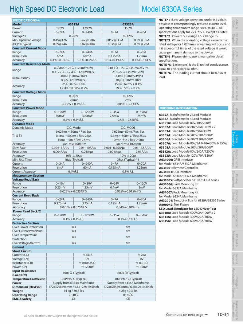
10-34All specifications are subject to change without notice. All specifications are subject to change without notice.
Flat PanelD
isplayPow
er Electronics
Electrical Safety
General
PurposePassive
Component
Semiconductor/
ICBattery Test & Autom
ationAutom
atedO
ptical Inspection Photovoltaic Test
& Automation
PXI Test &
Measurem
ent Video & Color
LED/
LightingO
ptical D
evicesIntelligent
Manufacturing System
Turnkey Test & Autom
ation High Speed DC Electronic Load Model 6330A Series
SPECIFICATIONS-4Model 63312A 63323APower 120W 1200W 350WCurrent 0~24A 0~240A 0~7A 0~70AVoltage*3 0~80V 0~120VMin. Operation Voltage (DC) *1 (Typical)
0.4V@12A 0.4V@120A 0.05V @ 3.5A 0.3V @ 35A 0.8V@24A 0.8V@240A 0.1V @ 7A 0.6V @ 70A
Constant Current ModeRange 0~24A 0~240A 0~7A 0~70AResolution 6mA 60mA 0.125mA 1.25mAAccuracy 0.1%+0.1%F.S. 0.1%+0.2%F.S. 0.1%+0.1%F.S. 0.1%+0.1%F.S.Constant Resistance Mode
Range6.25mΩ~25Ω (1200W/16V)
0.3125Ω~1.25kΩ (1200W/80V) 0.015Ω~150Ω (350W/24V)*4
2Ω~2kΩ (350W/120V)
Resolution*540mS (1200W/16V)80µS (1200W/80V)
1.33mS (350W/24V)*410µS (350W/120V)
Accuracy25Ω: 0.8S+ 0.8%
1.25kΩ: 0.08S+ 0.2% 150Ω: 67mS + 0.1%
2kΩ: 5mS + 0.2%Constant Voltage ModeRange 0~80V 0~120VResolution 20mV 2mVAccuracy 0.05% + 0.1%F.S. 0.05% + 0.1%F.S.Constant Power ModeRange 0~120W 0~1200W 0~35W 0~350WResolution 30mW 300mW 2.5mW 25mWAccuracy 0.5% + 0.5%F.S. 0.5% + 0.5%F.S.Dynamic ModeDynamic Mode C.C. Mode C.C. MODE
T1 & T20.025ms ~ 50ms / Res: 5µs0.1ms ~ 500ms / Res: 25µs
10ms ~ 50s / Res: 2.5ms
0.025ms~50ms/Res: 5µs0.1ms∼500ms / Res: 25µs
10ms∼50s / Res: 2.5msAccuracy 1µs/1ms+100ppm 1µs /1ms+100ppmSlew Rate 0.004~1A/µs 0.04~10A/µs 0.001~0.25A/µs 0.01~2.5A/µsResolution 0.004A/µs 0.04A/µs 0.001A/µs 0.01A/µsAccuracy 10% ±20µs 10% ±20µsMin. Rise Time 10µs (Typical) 25µs (Typical) *6Current 0~24A 0~240A 0~7A 0~70AResolution 6mA 60mA 0.125mA 1.25mACurrent Accuracy 0.4%F.S. 0.1% F.S.Measurement SectionVoltage Read Back Range 0~16V 0~80V 0~24V 0~120VResolution 0.25mV 1.25mV 0.4mV 2mVAccuracy 0.025% + 0.025%F.S. 0.025%+0.015% F.S.Current Read BackRange 0~24A 0~240A 0~7A 0~70AResolution 0.375mA 3.75mA 0.125mA 1.25mA Accuracy 0.075% + 0.075%F.S. 0.04%+0.04% F.S. Power Read Back*2Range 0~120W 0~1200W 0~35W 0~350WAccuracy 0.1% + 0.1%F.S. 0.1%+0.1% F.S.Protective SectionOver Power Protection Yes YesOver Current Protection Yes YesOver TemperatureProtection
Yes Yes
Over Voltage Alarm*3 Yes YesGeneralShort CircuitCurrent (CC) - ≒240A - ≒70AVoltage (CV) - 0V - 0VResistance (CR) - ≒0.00625Ω - ≒ 0.01ΩPower (CP) - ≒1200W - ≒ 350WInput Resistance(Load Off)
100kΩ (Typical) 800kΩ(Typical)
Temperature Coefficient 100PPM/˚C (Typical) 100PPM/˚C (Typical)Power Supply from 6334A Mainframe Supply from 6334A MainframeDimension (HxWxD) 172x329x495mm / 6.8x12.9x19.5inch 172x82x489.5mm / 6.8x3.2x19.3inchWeight 14 kg / 30.8 lbs 4.2kg / 9.3 lbsOperating Range 0~40˚C 0~40˚CEMC & Safety CE CE
NOTE*1 : Low voltage operation, under 0.8 volt, is possible at correspondingly reduced current level. Operating temperature range is 0ºC to 40˚C. All specifications apply for 25˚C±5˚C, except as notedNOTE*2 : Power F.S.=Vrange F.S. x Irange F.S.NOTE*3 : When the operating voltage exceeds the rated voltage for 1.02 times, a warning will occur and if it exceeds 1.1 times of the rated voltage, it would cause permanent damage to the device.NOTE*4 : Please refer to user's manual for detail specifications.NOTE *5 : S (siemens) is the SI unit of conductance, equal to one reciprocal ohm.NOTE *6 : The loading current should be 0.35A at least.
6332A: Mainframe for 2 Load Modules6334A: Mainframe for 4 Load Modules63301A: Load Module 80V/40A/200W63302A: Load Module 80V/20A/100W x 263303A: Load Module 80V/60A/300W63305A: Load Module 500V/10A/300W63306A: Load Module 80V/120A/600W63307A: Load Module 80V/5A & 40A/30W & 250W63308A: Load Module 500V/20A/600W63312A: Load Module 80V/240A/1200W63323A: Load Module 120V/70A/350WA631000: GPIB Interface for Model 6334A/6332A MainframeA631001: Remote ControllerA631003: USB Interface for Model 6334A/6332A MainframeA631005: Softpanel for 6310A/6330A seriesA631006: Rack Mounting Kit for Model 6332A MainframeA631007: Rack Mounting Kit for Model 6334A MainframeA632004: Sync. Link Box for 6330A/63200 SeriesA800042: Test FixtureLED Load Simulator for LED Driver Test63310A: Load Module 500V/2A/100W x 263313A: Load Module 300V/20A/300W63315A: Load Module 600V/20A/300W
ORDERING INFORMATION
• Continued on next page
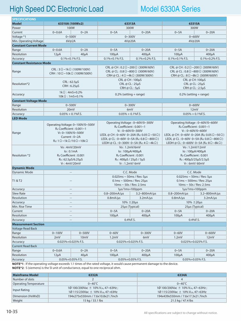
10-35 All specifications are subject to change without notice. All specifications are subject to change without notice.
High Speed DC Electronic Load Model 6330A Series
Mainframe Model 6332A 6334ANumber of slots 2 4Operating Temperature 0~40˚C 0~40˚C
Input Rating1Ø 100/200Vac ± 10% VLN, 47~63Hz ; 1Ø 115/230Vac ± 10% VLN, 47~63Hz
1Ø 100/200Vac ± 10% VLN, 47~63Hz ; 1Ø 115/230Vac ± 10% VLN, 47~63Hz
Dimension (HxWxD) 194x275x550mm / 7.6x10.8x21.7inch 194x439x550mm / 7.6x17.3x21.7inchWeight 15 kg / 33.1 lbs 21.5 kg / 47.4 lbs
SPECIFICATIONSModel 63310A (100Wx2) 63313A 63315APower 100W 300W 300WCurrent 0~0.6A 0~2A 0~5A 0~20A 0~5A 0~20AVoltage *1 0~500V 0~300V 0~600VMin. Operating Voltage 6V@2A 4V@20A 4V@20AConstant Current Mode Range 0~0.6A 0~2A 0~5A 0~20A 0~5A 0~20AResolution 12µA 40µA 100µA 400µA 100µA 400µAAccuracy 0.1%+0.1% F.S. 0.1%+0.1% F.S. 0.1%+0.2% F.S. 0.1%+0.1% F.S. 0.1%+0.2% F.S.Constant Resistance Mode
RangeCRL : 3Ω~1kΩ (100W/100V)
CRH : 10Ω~10kΩ (100W/500V)
CRL @ CH : 0.2Ω~200Ω (300W/60V)CRL @ CL : 0.8Ω~800Ω (300W/60V)CRH @ CL : 4Ω~4kΩ (300W/300V)
CRL @ CH : 0.2Ω~200Ω (300W/60V)CRL @ CL : 0.8Ω~800Ω (300W/60V)CRH @ CL : 8Ω~8kΩ (300W/600V)
Resolution*2CRL : 62.5µSCRH : 6.25µS
CRL @ CH : 100µSCRL @ CL : 25µSCRH @ CL : 5µS
CRL @ CH :100µSCRL @ CL : 25µSCRH @ CL : 2.5µS
Accuracy1kΩ : 4mS+0.2%
10kΩ : 1mS+0.1%0.2% (setting + range) 0.2% (setting + range)
Constant Voltage Mode Range 0~500V 0~300V 0~600VResolution 20mV 6mV 12mVAccuracy 0.05% + 0.1%F.S. 0.05% + 0.1%F.S. 0.05% + 0.1%F.S.LED Mode
Range
Operating Voltage: 0~100V/0~500V Rd Coefficient : 0.001~1
VF: 0~100V/0~500VCurrent : 0~2A
Rd: 1Ω~1kΩ/10Ω~10kΩ
Operating Voltage : 0~60V/0~300VRd Coefficient : 0.001~1
VF : 0~60V/0~300VLEDL @ CH : 0~60V- 0~20A (Rd: 0.05Ω~50Ω)LEDL @ CL : 0~60V- 0~5A (Rd: 0.8Ω~800Ω)LEDH @ CL : 0~300V- 0~5A (Rd: 4Ω~4kΩ)
Operating Voltage : 0~60V/0~600VRd Coefficient : 0.001~1
VF : 0~60V/0~600VLEDL @ CH : 0~60V- 0~20A (Rd: 0.05Ω~50Ω)LEDL @ CL : 0~60V- 0~5A (Rd: 0.8Ω~800Ω)LEDH @ CL : 0~600V- 0~5A (Rd: 8Ω~8kΩ)
Resolution *2
Vo : 4mV/20mVIo : 0.1mA
Rd Coefficient : 0.001Rd : 62.5µS/6.25µS
VF : 4mV/20mV
Vo : 1.2mV/6mVIo : 100µA/400µA
Rd Coefficient : 0.001Rd : 400µS / 25µS / 5µS
VF : 1.2mV/ 6mV
Vo : 1.2mV/12mVIo : 100µA/400µA
Rd Coefficient : 0.001Rd : 400µS/25µS/2.5µS
VF : 6mV/ 60mVDynamic ModeDynamic Mode -- C.C. Mode C.C. Mode
T1 & T2 --0.025ms ~ 50ms / Res: 5µs0.1ms ~ 500ms / Res: 25µs
10ms ~ 50s / Res: 2.5ms
0.025ms ~ 50ms / Res: 5µs0.1ms ~ 500ms / Res: 25µs
10ms ~ 50s / Res: 2.5msAccuracy -- 1µs/1ms+100ppm 1µs/1ms+100ppmSlew Rate -- 0.8~200mA/µs 3.2~800mA/µs 0.8~200mA/µs 3.2~800mA/µsResolution -- 0.8mA/µs 3.2mA/µs 0.8mA/µs 3.2mA/µsAccuracy -- 10% ±20µs 10% ±20µsMin. Rise Time -- 25µs (Typical) 25µs (Typical)Current -- 0~5A 0~20A 0~5A 0~20AResolution -- 100µA 400µA 100µA 400µAAccuracy -- 0.4%F.S. 0.4%F.S.Measurement SectionVoltage Read BackRange 0~100V 0~500V 0~60V 0~300V 0~60V 0~600VResolution 2mV 10mV 1.2mV 6mV 1.2mV 12mVAccuracy 0.025%+0.025% F.S. 0.025%+0.025% F.S. 0.025%+0.025% F.S.Current Read BackRange 0~0.6A 0~2A 0~5A 0~20A 0~5A 0~20AResolution 12µA 40µA 100µA 400µA 100µA 400µAAccuracy 0.05%+0.05% F.S. 0.05%+0.05% F.S. 0.05%+0.05% F.S.NOTE*1 : If the operating voltage exceeds 1.1 times of the rated voltage, it would cause permanent damage to the device.NOTE*2 : S (siemens) is the SI unit of conductance, equal to one reciprocal ohm.
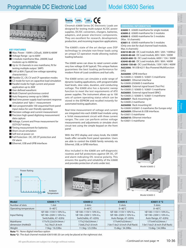
10-36All specifications are subject to change without notice. All specifications are subject to change without notice.
Flat PanelD
isplayPow
er Electronics
Electrical Safety
General
PurposePassive
Component
Semiconductor/
ICBattery Test & Autom
ationAutom
atedO
ptical Inspection Photovoltaic Test
& Automation
PXI Test &
Measurem
ent Video & Color
LED/
LightingO
ptical D
evicesIntelligent
Manufacturing System
Turnkey Test & Autom
ation
Chroma's 63600 Series DC Electronic Loads are designed for testing multi-output AC/DC power supplies, DC/DC converters, chargers, batteries, adapters, and power electronic components. They are excellent for research, development, production, and incoming inspection applications.
The 63600's state of the art design uses DSP technology to simulate non-linear loads using an unique CZ operation mode allowing realistic loading behavior.
The 63600 series can draw its rated current under very low voltage (0.4V typical). This unique feature guarantees the best loading performance for modern Point-of-Load conditions and fuel cells.
The 63600 series can simulate a wide range of dynamic loading applications, with programmable load levels, slew rates, duration, and conducting voltage. The 63600 also has a dynamic sweep function to meet the test requirements of ATX power supplies. The instrument allows up to 100 sets of system operating status which can be stored in the EEPROM and recalled instantly for automated testing application.
Real time measurement of voltage and current are integrated into each 63600 load module using a 16-bit measurement circuit with three current ranges. The user can perform online voltage measurements and adjustments or simulate short circuit test using the simple keypad on the front panel.
With the VFD display and rotary knob, the 63600 loads offer versatile front panel operation. Users are able to control the 63600 family remotely via Ethernet, USB, or GPIB interface.
Also included in the 63600 are self-diagnostic routines and full protections against OP, OC, OT and alarm indicating OV, reverse polarity. This ensures the quality and reliability of the 63600 and provides protection of units under test.
KEY FEATURES Max. Power : 100W x 2(Dual), 300W & 400W Voltage Range : up to 600V 5 module mainframe Max. 2000W, load modules up to 400W/ea Up to 10 channels in one mainframe, fit for testing multiple output SMPS 0.4V @ 80A (Typical) low voltage operating characteristics Flexible CC, CR, CV and CP operation modes CZ mode for turn on capacitive load simulation Parallel mode for high current and power application up to 2kW User defined waveformMulti Channel synchronous control Auto frequency sweep up to 50kHz Real time power supply load transient response simulation and Vpk+/- measurement User programmable 100 sequential front panel input status for user-friendly operating Precision voltage and current measurement Precision high speed digitizing measurement/ data capture Voltage, Current and Pmax measurement for OCP/OLP testing Timing measurement for batteries Short circuit simulation Self-test at power-on Full Protection : OC, OP, OT protection and OV alarm Ethernet, USB and GPIB interfaces
Programmable DC Electronic Load Model 63600 Series
ORDERING INFORMATION
63600-1 : 63600 mainframe for single module63600-2 : 63600 mainframe for 2 modules63600-5 : 63600 mainframe for 5 modules(Max. 10 channels)63601-5 : 63600 mainframe for 5 modules(Only one slot for dual channel load module, Max. 6 channels)63610-80-20 : DC Load module, 80V / 20A / 100Wx263630-80-60 : DC Load module, 80V / 60A / 300W63630-600-15 : DC Load module, 600V / 15A / 300W63640-80-80 : DC Load module, 80V / 80A / 400W63640-150-60 : DC Load Module, 150V / 60A / 400WA632006 : NI USB-6211 Bus-Powered Multifunction DAQA636000 : GPIB interface for 63600-2 / 63600-5 / 63601-5 mainframeA636001 : Ethernet interface for 63600-2/63600-5 mainframeA636003 : External signal board (Test Pin) for 63600-2 / 63600-5 / 63601-5 mainframeA636005 : External signal board (BNC) for 63600-2 / 63600-5 / 63601-5 mainframeA636007 : Rack mounting kit for 63600-2 mainframeA636008 : Rack mounting kit for 63600-5/63601-5 mainframe (for Europe only)A636009 : Ethernet & USB interfaces for 63601-5 mainframeA636010 : Ethernet interface for 63601-5 mainframe
Model 63600-1 *1 63600-2 63600-5 63601-5 *2Number of slots 1 slot 2 slots 5 slots 5 slotsOperating temperature 0~40˚C 0~40˚C 0~40˚C 0~40˚C
Input Rating1Ø 100~115V±10% VLN,1Ø 190~230V±10% VLN,
Switchable, 47~63Hz
1Ø 100~115V±10% VLN,1Ø 190~230V±10% VLN,
Switchable, 47~63Hz
1Ø 100~115V±10% VLN,1Ø 190~230V±10% VLN,
Auto Range, 47~63Hz
1Ø 100~115V±10% VLN,1Ø 190~230V±10% VLN,
Auto Range, 47~63Hz Mainframe dimension (HxWxD)
177x70.22x554.9mm / 7x2.76x21.8 inch
177x210x554mm / 7.0x8.27x21.8 inch
177x447x554mm / 7.0x17.6x21.8 inch (Full Rack)
177x447x554mm / 7.0x17.6x21.8 inch (Full Rack)
Weight 7.5kg / 16.53lbs 11.5kg / 23.35lbs 15.6kg / 34.39lbs 15.6kg / 34.39lbsNote *1 : None digital interface optionNote *2 : The dual channel module 63610-80-20 can only be placed at the rightmost slot.
Power Rating
Model 63600-2
Model 63600-5
100%
87.5%
˚C Ambient Temperature 35 40
• Continued on next page
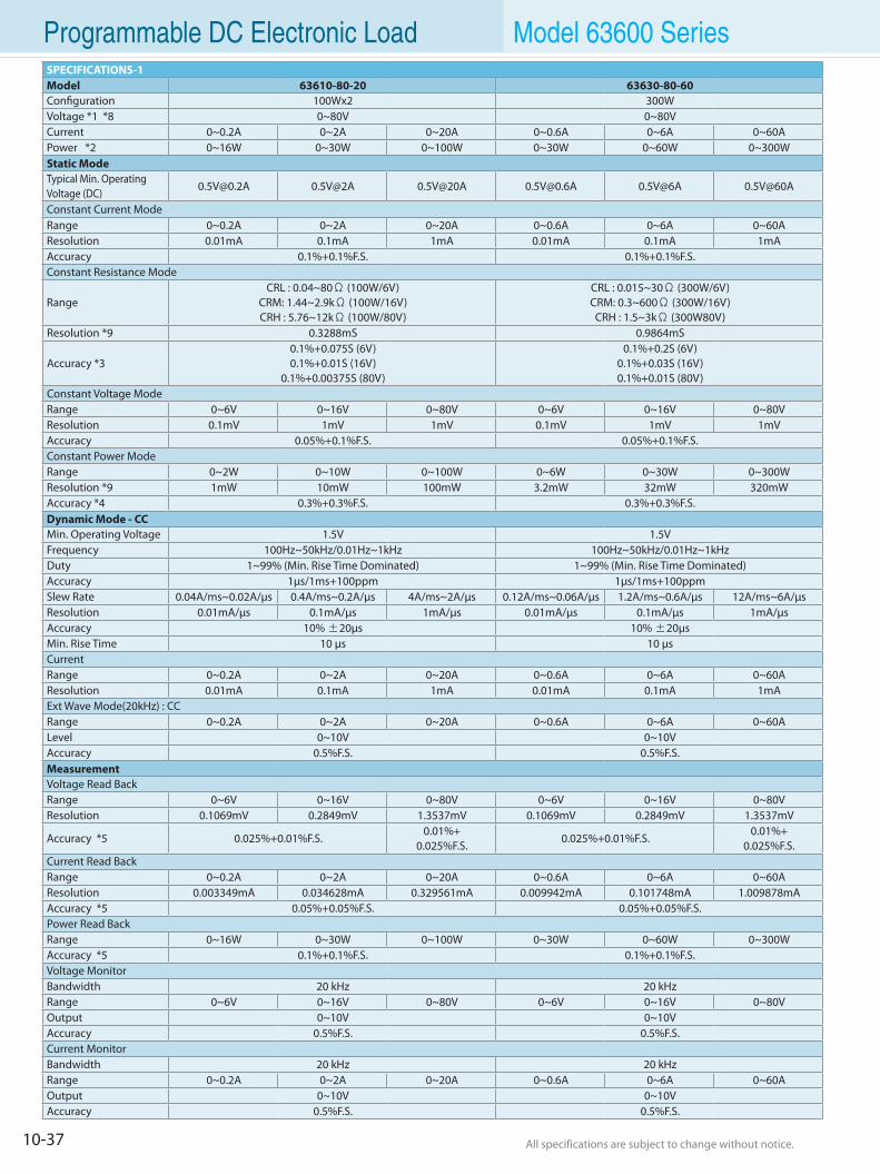
10-37 All specifications are subject to change without notice. All specifications are subject to change without notice.
Programmable DC Electronic Load Model 63600 SeriesSPECIFICATIONS-1Model 63610-80-20 63630-80-60Configuration 100Wx2 300WVoltage *1 *8 0~80V 0~80VCurrent 0~0.2A 0~2A 0~20A 0~0.6A 0~6A 0~60APower *2 0~16W 0~30W 0~100W 0~30W 0~60W 0~300WStatic ModeTypical Min. OperatingVoltage (DC)
[email protected] 0.5V@2A 0.5V@20A [email protected] 0.5V@6A 0.5V@60A
Constant Current ModeRange 0~0.2A 0~2A 0~20A 0~0.6A 0~6A 0~60AResolution 0.01mA 0.1mA 1mA 0.01mA 0.1mA 1mAAccuracy 0.1%+0.1%F.S. 0.1%+0.1%F.S.Constant Resistance Mode
RangeCRL : 0.04~80Ω (100W/6V)
CRM: 1.44~2.9kΩ (100W/16V)CRH : 5.76~12kΩ (100W/80V)
CRL : 0.015~30Ω (300W/6V) CRM: 0.3~600Ω (300W/16V) CRH : 1.5~3kΩ (300W80V)
Resolution *9 0.3288mS 0.9864mS
Accuracy *30.1%+0.075S (6V)0.1%+0.01S (16V)
0.1%+0.00375S (80V)
0.1%+0.2S (6V)0.1%+0.03S (16V)0.1%+0.01S (80V)
Constant Voltage Mode Range 0~6V 0~16V 0~80V 0~6V 0~16V 0~80VResolution 0.1mV 1mV 1mV 0.1mV 1mV 1mVAccuracy 0.05%+0.1%F.S. 0.05%+0.1%F.S.Constant Power Mode Range 0~2W 0~10W 0~100W 0~6W 0~30W 0~300WResolution *9 1mW 10mW 100mW 3.2mW 32mW 320mWAccuracy *4 0.3%+0.3%F.S. 0.3%+0.3%F.S.Dynamic Mode - CCMin. Operating Voltage 1.5V 1.5VFrequency 100Hz~50kHz/0.01Hz~1kHz 100Hz~50kHz/0.01Hz~1kHzDuty 1~99% (Min. Rise Time Dominated) 1~99% (Min. Rise Time Dominated)Accuracy 1µs/1ms+100ppm 1µs/1ms+100ppmSlew Rate 0.04A/ms~0.02A/µs 0.4A/ms~0.2A/µs 4A/ms~2A/µs 0.12A/ms~0.06A/µs 1.2A/ms~0.6A/µs 12A/ms~6A/µsResolution 0.01mA/µs 0.1mA/µs 1mA/µs 0.01mA/µs 0.1mA/µs 1mA/µsAccuracy 10% ±20µs 10% ±20µsMin. Rise Time 10 µs 10 µsCurrent Range 0~0.2A 0~2A 0~20A 0~0.6A 0~6A 0~60AResolution 0.01mA 0.1mA 1mA 0.01mA 0.1mA 1mAExt Wave Mode(20kHz) : CCRange 0~0.2A 0~2A 0~20A 0~0.6A 0~6A 0~60ALevel 0~10V 0~10VAccuracy 0.5%F.S. 0.5%F.S.Measurement Voltage Read BackRange 0~6V 0~16V 0~80V 0~6V 0~16V 0~80VResolution 0.1069mV 0.2849mV 1.3537mV 0.1069mV 0.2849mV 1.3537mV
Accuracy *5 0.025%+0.01%F.S.0.01%+
0.025%F.S.0.025%+0.01%F.S.
0.01%+0.025%F.S.
Current Read BackRange 0~0.2A 0~2A 0~20A 0~0.6A 0~6A 0~60AResolution 0.003349mA 0.034628mA 0.329561mA 0.009942mA 0.101748mA 1.009878mAAccuracy *5 0.05%+0.05%F.S. 0.05%+0.05%F.S. Power Read BackRange 0~16W 0~30W 0~100W 0~30W 0~60W 0~300WAccuracy *5 0.1%+0.1%F.S. 0.1%+0.1%F.S.Voltage MonitorBandwidth 20 kHz 20 kHzRange 0~6V 0~16V 0~80V 0~6V 0~16V 0~80VOutput 0~10V 0~10VAccuracy 0.5%F.S. 0.5%F.S.Current MonitorBandwidth 20 kHz 20 kHzRange 0~0.2A 0~2A 0~20A 0~0.6A 0~6A 0~60AOutput 0~10V 0~10VAccuracy 0.5%F.S. 0.5%F.S.
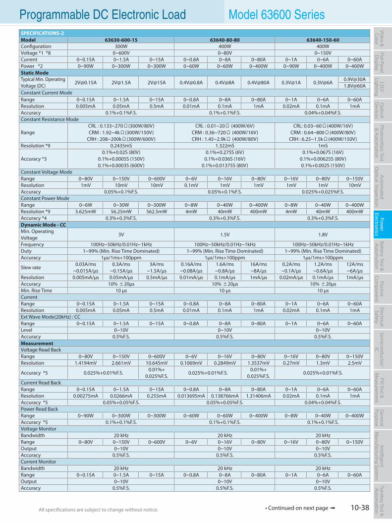
10-38All specifications are subject to change without notice. All specifications are subject to change without notice.
Flat PanelD
isplayPow
er Electronics
Electrical Safety
General
PurposePassive
Component
Semiconductor/
ICBattery Test & Autom
ationAutom
atedO
ptical Inspection Photovoltaic Test
& Automation
PXI Test &
Measurem
ent Video & Color
LED/
LightingO
ptical D
evicesIntelligent
Manufacturing System
Turnkey Test & Autom
ation Programmable DC Electronic Load Model 63600 SeriesSPECIFICATIONS-2Model 63630-600-15 63640-80-80 63640-150-60Configuration 300W 400W 400WVoltage *1 *8 0~600V 0~80V 0~150VCurrent 0~0.15A 0~1.5A 0~15A 0~0.8A 0~8A 0~80A 0~1A 0~6A 0~60APower *2 0~90W 0~300W 0~300W 0~60W 0~60W 0~400W 0~90W 0~400W 0~400WStatic ModeTypical Min. OperatingVoltage (DC)
[email protected] [email protected] 2V@15A [email protected] 0.4V@8A 0.4V@80A 0.3V@1A [email protected]@30A1.8V@60A
Constant Current ModeRange 0~0.15A 0~1.5A 0~15A 0~0.8A 0~8A 0~80A 0~1A 0~6A 0~60AResolution 0.005mA 0.05mA 0.5mA 0.01mA 0.1mA 1mA 0.02mA 0.1mA 1mAAccuracy 0.1%+0.1%F.S. 0.1%+0.1%F.S. 0.04%+0.04%F.S.Constant Resistance Mode
RangeCRL : 0.133~270Ω(300W/80V)CRM : 1.92~4kΩ(300W/150V)
CRH : 208~200kΩ(300W/600V)
CRL : 0.01~20Ω (400W/6V) CRM : 0.36~720Ω (400W/16V) CRH : 1.45~2.9kΩ (400W/80V)
CRL: 0.03~60Ω(400W/16V)CRM : 0.64~800Ω(400W/80V)
CRH : 6.25~1.5kΩ(400W/150V)Resolution *9 0.2435mS 1.322mS 1mS
Accuracy *30.1%+0.02S (80V)
0.1%+0.0005S (150V)0.1%+0.0003S (600V)
0.1%+0.275S (6V)0.1%+0.036S (16V)
0.1%+0.01375S (80V)
0.1%+0.067S (16V)0.1%+0.00625S (80V)0.1%+0.002S (150V)
Constant Voltage Mode Range 0~80V 0~150V 0~600V 0~6V 0~16V 0~80V 0~16V 0~80V 0~150VResolution 1mV 10mV 10mV 0.1mV 1mV 1mV 1mV 1mV 10mVAccuracy 0.05%+0.1%F.S. 0.05%+0.1%F.S. 0.025%+0.025%F.S.Constant Power Mode Range 0~6W 0~30W 0~300W 0~8W 0~40W 0~400W 0~8W 0~40W 0~400WResolution *9 5.625mW 56.25mW 562.5mW 4mW 40mW 400mW 4mW 40mW 400mWAccuracy *4 0.3%+0.3%F.S. 0.3%+0.3%F.S. 0.3%+0.3%F.S.Dynamic Mode - CCMin. Operating Voltage
3V 1.5V 1.8V
Frequency 100Hz~50kHz/0.01Hz~1kHz 100Hz~50kHz/0.01Hz~1kHz 100Hz~50kHz/0.01Hz~1kHzDuty 1~99% (Min. Rise Time Dominated) 1~99% (Min. Rise Time Dominated) 1~99% (Min. Rise Time Dominated)Accuracy 1µs/1ms+100ppm 1µs/1ms+100ppm 1µs/1ms+100ppm
Slew rate0.03A/ms
~0.015A/µs0.3A/ms
~0.15A/µs3A/ms
~1.5A/µs0.16A/ms ~0.08A/µs
1.6A/ms ~0.8A/µs
16A/ms~8A/µs
0.2A/ms ~0.1A/µs
1.2A/ms ~0.6A/µs
12A/ms~6A/µs
Resolution 0.005mA/µs 0.05mA/µs 0.5mA/µs 0.01mA/µs 0.1mA/µs 1mA/µs 0.02mA/µs 0.1mA/µs 1mA/µsAccuracy 10% ±20µs 10% ±20µs 10% ±20µsMin. Rise Time 10 µs 10 µs 10 µsCurrent Range 0~0.15A 0~1.5A 0~15A 0~0.8A 0~8A 0~80A 0~1A 0~6A 0~60AResolution 0.005mA 0.05mA 0.5mA 0.01mA 0.1mA 1mA 0.02mA 0.1mA 1mAExt Wave Mode(20kHz) : CCRange 0~0.15A 0~1.5A 0~15A 0~0.8A 0~8A 0~80A 0~1A 0~6A 0~60ALevel 0~10V 0~10V 0~10VAccuracy 0.5%F.S. 0.5%F.S. 0.5%F.S.Measurement Voltage Read BackRange 0~80V 0~150V 0~600V 0~6V 0~16V 0~80V 0~16V 0~80V 0~150VResolution 1.4194mV 2.661mV 10.645mV 0.1069mV 0.2849mV 1.3537mV 0.27mV 1.3mV 2.5mV
Accuracy *5 0.025%+0.01%F.S.0.01%+
0.025%F.S.0.025%+0.01%F.S.
0.01%+0.025%F.S.
0.025%+0.01%F.S.
Current Read BackRange 0~0.15A 0~1.5A 0~15A 0~0.8A 0~8A 0~80A 0~1A 0~6A 0~60AResolution 0.00275mA 0.0266mA 0.255mA 0.013695mA 0.138766mA 1.31406mA 0.02mA 0.1mA 1mAAccuracy *5 0.05%+0.05%F.S. 0.05%+0.05%F.S. 0.04%+0.04%F.S.Power Read BackRange 0~90W 0~300W 0~300W 0~60W 0~60W 0~400W 0~8W 0~40W 0~400WAccuracy *5 0.1%+0.1%F.S. 0.1%+0.1%F.S. 0.1%+0.1%F.S.Voltage MonitorBandwidth 20 kHz 20 kHz 20 kHzRange 0~80V 0~150V 0~600V 0~6V 0~16V 0~80V 0~16V 0~80V 0~150VOutput 0~10V 0~10V 0~10VAccuracy 0.5%F.S. 0.5%F.S. 0.5%F.S.Current MonitorBandwidth 20 kHz 20 kHz 20 kHzRange 0~0.15A 0~1.5A 0~15A 0~0.8A 0~8A 0~80A 0~1A 0~6A 0~60AOutput 0~10V 0~10V 0~10VAccuracy 0.5%F.S. 0.5%F.S. 0.5%F.S.
• Continued on next page
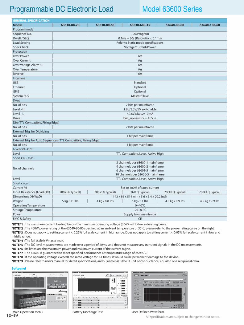
10-39 All specifications are subject to change without notice. All specifications are subject to change without notice.
Programmable DC Electronic Load Model 63600 SeriesGENERAL SPECIFICATIONModel 63610-80-20 63630-80-60 63630-600-15 63640-80-80 63640-150-60Program modeSequence No. 100/ProgramDwell / SEQ 0.1ms ~ 30s (Resolution : 0.1ms)Load Setting Refer to Static mode specificationsSpec Check Voltage/Current/PowerProtectionOver Power YesOver Current YesOver Voltage Alarm*8 YesOver Temperature YesReverse YesInterfaceUSB StandardEthernet OptionalGPIB OptionalSystem BUS Master/SlaveDoutNo. of bits 2 bits per mainframeLevel - H 1.8V/3.3V/5V switchableLevel - L <0.6V@Isink=10mADrive Pull_up resistor = 4.7kΩDin (TTL Compatible, Rising Edge)No. of bits 2 bits per mainframeExternal Trig. for Digitizing No. of bits 1 bit per mainframeExternal Trig. for Auto Sequences (TTL Compatible, Rising Edge)No. of bits 1 bit per mainframeLoad ON - O/P Level TTL Compatible, Level, Active HighShort ON - O/P
No. of channels
2 channels per 63600-1 mainframe4 channels per 63600-2 mainframe6 channels per 63601-5 mainframe
10 channels per 63600-5 mainframeLevel TTL Compatible, Level, Active HighShort circuitCurrent *6 Set to 100% of rated currentInput Resistance (Load Off) 700kΩ(Typical) 700kΩ(Typical) 2MΩ(Typical) 700kΩ(Typical) 700kΩ(Typical)Dimensions (HxWxD) 142 x 86 x 514 mm / 5.6 x 3.4 x 20.2 inchWeight 5 kg / 11 lbs 4 kg / 8.8 lbs 5 kg / 11 lbs 4.5 kg / 9.9 lbs 4.5 kg / 9.9 lbsOperating Temperature 0~40˚CStorage Temperature -20~80˚CPower Supply from mainframeEMC & Safety CE
NOTE*1 : The maximum current loading below the minimum operating voltage (0.5V) will follow a derating curve.NOTE*2 : The 400W power rating of the 63640-80-80 specified at an ambient temperature of 35˚C, please refer to the power rating curve on the right.NOTE*3 : Does not apply to setting current < 0.25% full scale current in high range. Does not apply to setting current < 0.05% full scale current in low andmiddle range.NOTE*4 : The full scale is Vmax x Imax. NOTE*5 : The DC level measurements are made over a period of 20ms, and does not measure any transient signals in the DC measurements.NOTE*6 : Its limits are the maximum power and maximum current of the current ragne. NOTE*7 : The 63600 is guaranteed to meet specified performance at temperature range of 25±5˚C.NOTE*8 : If the operating voltage exceeds the rated voltage for 1.1 times, it would cause permanent damage to the device.NOTE*9 : Please refer to user's manual for detail specifications, and S (siemens) is the SI unit of conductance, equal to one reciprocal ohm.
Main Operation Menu Battery Discharge Test User Defined Waveform
Softpanel
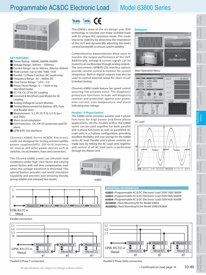
10-40All specifications are subject to change without notice. All specifications are subject to change without notice.
Flat PanelD
isplayPow
er Electronics
Electrical Safety
General
PurposePassive
Component
Semiconductor/
ICBattery Test & Autom
ationAutom
atedO
ptical Inspection Photovoltaic Test
& Automation
PXI Test &
Measurem
ent Video & Color
LED/
LightingO
ptical D
evicesIntelligent
Manufacturing System
Turnkey Test & Autom
ation Programmable AC&DC Electronic Load Model 63800 Series
KEY FEATURES Power Rating : 1800W, 3600W, 4500W Voltage Range : 50Vrms ~ 350Vrms Current Range : Up to 18Arms, 36Arms, 45Arms Peak Current : Up to 54A, 108A, 135A Parallel / 3-Phase Function (AC mode only) Frequency Range : 45 ~ 440Hz, DC Crest Factor Range : 1.414 ~ 5.0 Power Factor Range : 0 ~ 1 lead or lag (Rectified mode) CC, CR, CV, CP for DC Loading Constant & Rectified Load Modes for AC Loading Analog Voltage & Current Monitor Timing Measurement for Battery, UPS, Fuse and Breaker tests Measurement : V, I, PF, CF, P, Q, S, F, R, Ip+/- and THDv Short circuit simulation Full Protection : OC, OP, OT protection and OV alarm GPIB & RS-232 interfaces
C h r o m a's 63800 S e r i e s AC&D C E l e c t r o n i c Loads are designed for testing uninterruptible p o w e r s u p p l i e s(U P S), O f f- G r i d I nv e r t e r s , AC sources and other power devices such as switches, circuit breakers, fuses and connectors.
The Chroma 63800 Loads can simulate load conditions under high crest factor and varying power factors with real time compensation even when the voltage waveform is distorted. This special feature provides real world simulation capability and prevents over-stressing thereby giving reliable and unbiased test results.
63802 : Programmable AC & DC Electronic Load 350V/18A/1800W63803 : Programmable AC & DC Electronic Load 350V/36A/3600W63804 : Programmable AC & DC Electronic Load 350V/45A/4500WA638001 : Rack Mounting Kit for Model 63802A638002 : Rack Mounting Kit for Model 63803/63804
ORDERING INFORMATION
The 63800's state of the art design uses DSP technology to simulate non-linear rectified loads with its unique RLC operation mode. This mode improves stability by detecting the impedance of the UUT and dynamically adjusting the load's control bandwidth to ensure system stability.
Comprehensive measurements allow users to monitor the output performance of the UUT. Additionally, voltage & current signals can be routed to an oscilloscope through analog outputs. The instrument's GPIB/RS-232 interface options provide remote control & monitor for system integration. Built-in digital outputs may also be used to control external relays for short circuit (crowbar) testing.
Chroma's 63800 Loads feature fan speed control ensuring low acoustic noise. The diagnosis/protection functions include self-diagnosis routines and protection against over-power, over-current, over-temp erature and a larm indicating over-voltage.
Parallel / 3-Phase ControlThe 63800 series provides parallel and 3-phase func tions for high p ower and thre e phase applications. All the models within the 63800 series can be used together for both parallel and 3-phase functions as well as paralleled AC Load units in a 3-phase configuration, providing excellent flexibility and cost savings for the 63800 series AC load. Parallel and 3-phase controls are made easy by linking the AC Load units together and control of all AC load units is performed through the Master Unit.
Main Operation Menu
63802
Softpanel
AC Load
Parallel connection
Parallel/3-Phase Y connection Parallel/3-Phase Delta connection
• Continued on next page
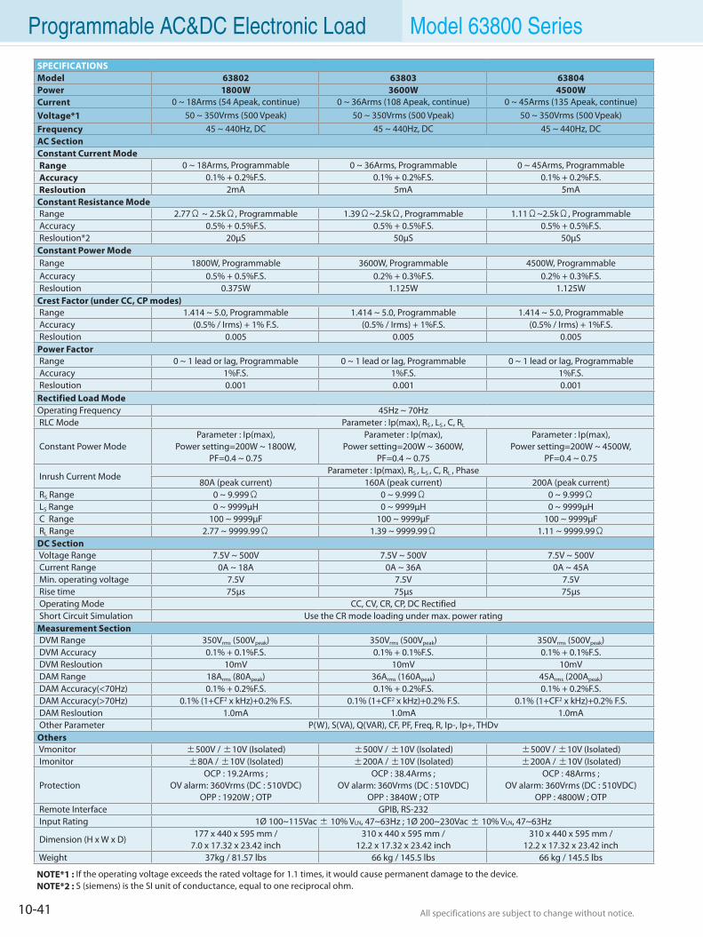
10-41 All specifications are subject to change without notice. All specifications are subject to change without notice.
Rectified Load ModeOperating Frequency 45Hz ~ 70Hz RLC Mode Parameter : Ip(max), RS , LS , C, RL
Constant Power ModeParameter : Ip(max),
Power setting=200W ~ 1800W, PF=0.4 ~ 0.75
Parameter : Ip(max), Power setting=200W ~ 3600W,
PF=0.4 ~ 0.75
Parameter : Ip(max), Power setting=200W ~ 4500W,
PF=0.4 ~ 0.75
Inrush Current ModeParameter : Ip(max), RS , LS , C, RL , Phase
80A (peak current) 160A (peak current) 200A (peak current) RS Range 0 ~ 9.999Ω 0 ~ 9.999Ω 0 ~ 9.999Ω LS Range 0 ~ 9999µH 0 ~ 9999µH 0 ~ 9999µH C Range 100 ~ 9999µF 100 ~ 9999µF 100 ~ 9999µF RL Range 2.77 ~ 9999.99Ω 1.39 ~ 9999.99Ω 1.11 ~ 9999.99ΩDC Section Voltage Range 7.5V ~ 500V 7.5V ~ 500V 7.5V ~ 500V Current Range 0A ~ 18A 0A ~ 36A 0A ~ 45A Min. operating voltage 7.5V 7.5V 7.5V Rise time 75µs 75µs 75µs Operating Mode CC, CV, CR, CP, DC Rectified Short Circuit Simulation Use the CR mode loading under max. power ratingMeasurement Section DVM Range 350Vrms (500Vpeak) 350Vrms (500Vpeak) 350Vrms (500Vpeak) DVM Accuracy 0.1% + 0.1%F.S. 0.1% + 0.1%F.S. 0.1% + 0.1%F.S. DVM Resloution 10mV 10mV 10mV DAM Range 18Arms (80Apeak) 36Arms (160Apeak) 45Arms (200Apeak) DAM Accuracy(<70Hz) 0.1% + 0.2%F.S. 0.1% + 0.2%F.S. 0.1% + 0.2%F.S. DAM Accuracy(>70Hz) 0.1% (1+CF2 x kHz)+0.2% F.S. 0.1% (1+CF2 x kHz)+0.2% F.S. 0.1% (1+CF2 x kHz)+0.2% F.S. DAM Resloution 1.0mA 1.0mA 1.0mA Other Parameter P(W), S(VA), Q(VAR), CF, PF, Freq, R, Ip-, Ip+, THDvOthers Vmonitor ±500V / ±10V (Isolated) ±500V / ±10V (Isolated) ±500V / ±10V (Isolated) Imonitor ±80A / ±10V (Isolated) ±200A / ±10V (Isolated) ±200A / ±10V (Isolated)
ProtectionOCP : 19.2Arms ;
OV alarm: 360Vrms (DC : 510VDC)OPP : 1920W ; OTP
OCP : 38.4Arms ; OV alarm: 360Vrms (DC : 510VDC)
OPP : 3840W ; OTP
OCP : 48Arms ; OV alarm: 360Vrms (DC : 510VDC)
OPP : 4800W ; OTP Remote Interface GPIB, RS-232 Input Rating 1Ø 100~115Vac ± 10% VLN, 47~63Hz ; 1Ø 200~230Vac ± 10% VLN, 47~63Hz
Dimension (H x W x D)177 x 440 x 595 mm /
7.0 x 17.32 x 23.42 inch310 x 440 x 595 mm /
12.2 x 17.32 x 23.42 inch310 x 440 x 595 mm /
12.2 x 17.32 x 23.42 inch Weight 37kg / 81.57 lbs 66 kg / 145.5 lbs 66 kg / 145.5 lbs
Programmable AC&DC Electronic Load Model 63800 Series
NOTE*1 : If the operating voltage exceeds the rated voltage for 1.1 times, it would cause permanent damage to the device.NOTE*2 : S (siemens) is the SI unit of conductance, equal to one reciprocal ohm.
SPECIFICATIONSModel 63802 63803 63804Power 1800W 3600W 4500WCurrent 0 ~ 18Arms (54 Apeak, continue) 0 ~ 36Arms (108 Apeak, continue) 0 ~ 45Arms (135 Apeak, continue)Voltage*1 50 ~ 350Vrms (500 Vpeak) 50 ~ 350Vrms (500 Vpeak) 50 ~ 350Vrms (500 Vpeak)Frequency 45 ~ 440Hz, DC 45 ~ 440Hz, DC 45 ~ 440Hz, DCAC SectionConstant Current Mode Range 0 ~ 18Arms, Programmable 0 ~ 36Arms, Programmable 0 ~ 45Arms, Programmable Accuracy 0.1% + 0.2%F.S. 0.1% + 0.2%F.S. 0.1% + 0.2%F.S. Resloution 2mA 5mA 5mAConstant Resistance Mode Range 2.77Ω ~ 2.5kΩ, Programmable 1.39Ω~2.5kΩ, Programmable 1.11Ω~2.5kΩ, Programmable Accuracy 0.5% + 0.5%F.S. 0.5% + 0.5%F.S. 0.5% + 0.5%F.S. Resloution*2 20µS 50µS 50µSConstant Power Mode Range 1800W, Programmable 3600W, Programmable 4500W, Programmable Accuracy 0.5% + 0.5%F.S. 0.2% + 0.3%F.S. 0.2% + 0.3%F.S. Resloution 0.375W 1.125W 1.125WCrest Factor (under CC, CP modes) Range 1.414 ~ 5.0, Programmable 1.414 ~ 5.0, Programmable 1.414 ~ 5.0, Programmable Accuracy (0.5% / Irms) + 1% F.S. (0.5% / Irms) + 1%F.S. (0.5% / Irms) + 1%F.S. Resloution 0.005 0.005 0.005Power Factor Range 0 ~ 1 lead or lag, Programmable 0 ~ 1 lead or lag, Programmable 0 ~ 1 lead or lag, Programmable Accuracy 1%F.S. 1%F.S. 1%F.S. Resloution 0.001 0.001 0.001
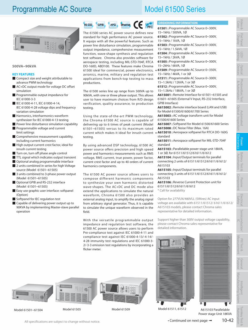
10-42All specifications are subject to change without notice. All specifications are subject to change without notice.
Flat PanelD
isplayPow
er Electronics
Electrical Safety
General
PurposePassive
Component
Semiconductor/
ICBattery Test & Autom
ationAutom
atedO
ptical Inspection Photovoltaic Test
& Automation
PXI Test &
Measurem
ent Video & Color
LED/
LightingO
ptical D
evicesIntelligent
Manufacturing System
Turnkey Test & Autom
ation Programmable AC Source Model 61500 Series
500VA~90kVA
KEY FEATURES Compact size and weight attributable to
advance PWM technology AC+DC output mode for voltage DC offset
simulation Programmable output impedance for IEC 61000-3-3 IEC 61000-4-11, IEC 61000-4-14, IEC 61000-4-28 voltage dips and frequency variation simulation Harmonics, interharmonics waveform
synthesizer for IEC 61000-4-13 testing Power line disturbance simulation capability Programmable voltage and current limit settings Comprehensive measurement capability,
including current harmonics High output current crest factor, ideal for
inrush current testing Turn on, turn off phase angle control TTL signal which indicates output transient Optional analog programmable interface 2 units combined in series for high Voltage
source (Model 61501~61505) 3 units combined to 3-phase power output (Model 61501~61505) Optional GPIB and RS-232 interface (Model 61501~61505) Easy use graphic user interface: softpanel
(Option) Softpanel for IEC regulation test Capable of delivering power output up to
90KVA by implementing Master-slave parallel operation
The 61500 series AC power source defines new standard for high performance AC power source. It equips with all the powerful features. Such as power line disturbance simulation, programmable output impedance, comprehensive measurement function, wave-shape synthesis and regulation test software. Chroma also provides software for aerospace testing, including MIL-STD-704F, RTCA DO-160D, ABD100. These features make Chroma 61500 ideal for commercial, power electronics, avionics, marine, military and regulation test applications from bench-top testing to mass productions.
The 61500 series line up range from 500VA up to 90kVA, with one or three phase output. This allows user to have maximum choices from R/D design verification, quality assurance, to production testing.
Using the state-of-the-art PWM technology, the Chroma 61500 AC source is capable of delivering up to 6 times of peak current (Model 61501~61505) versus to its maximum rated current which makes it ideal for inrush current testing.
By using advanced DSP technology, 61500 AC power source offers precision and high speed power and harmonics measurements such as RMS voltage, RMS current, true power, power factor, current crest factor and up to 40 orders of current harmonics components.
The 61500 AC power source allows users to compose di f ferent harmonic components to synthesize your own harmonic distorted wave-shapes. The AC+DC and DC mode also extend the applications to simulate the natural waveform, Chroma 61500 also provides an external analog input, to amplify the analog signal from arbitrary signal generator. Thus, it is capable to simulate the unique waveform observed in the field.
Wi t h t h e ve r s at i l e p ro gra m m a b l e o u t p u t impedance and regulation test software, the 61500 AC power source allows users to perform Pre-compliance test against IEC 61000-4-11 and compliance test against IEC 61000-4-13/-4-14/-4-28 immunity test regulations and IEC 61000-3-2/-3-3 emission test regulations by incorporating a flicker meter.
61501 : Programmable AC Source 0~300V, 15~1kHz / 500VA, 1Ø61502 : Programmable AC Source 0~300V, 15~1kHz / 1kVA, 1Ø61503 : Programmable AC Source 0~300V, 15~1kHz / 1.5kVA, 1Ø61504 : Programmable AC Source 0~300V, 15~1kHz / 2kVA, 1Ø61505 : Programmable AC Source 0~300V, 15~2kHz / 6kVA, 1Ø61509 : Programmable AC Source 0~350V, 15~1kHz / 4kVA, 1 or 3Ø61511 : Programmable AC Source 0~300V, 15~1.5kHz / 12kVA, 1 or 3Ø61512 : Programmable AC Source 0~300V, 15~1.5kHz / 18kVA, 1 or 3ØA615001 : Remote Interface for 61501~61505 and 61601~61605 (External V Input, RS-232 Interface, GPIB Interface)A615002 : Remote interface board (LAN and USB)for Model 61500/61600/61700 SeriesA615003 : AC voltage transform unit for Model 61500/61600 SeriesA615007 : Softpanel for Model 61500/61600 SeriesA615008 : DC Noise Filter (Max. 16A)A615010 : Aerospace softpanel for RTCA DO-160G standardA615011 : Aerospace softpanel for MIL-STD-704F standardA615103 : Parallelable power stage unit 18kVA, 1 or 3Ø, for 61511/61512/61611/61612A615104 : Input/Output terminals for parallel connecting 2 units of 61511/61512/61611/61612/ A615103A615105 : Input/Output terminals for parallel connecting 3 units of 61511/61512/61611/61612/ A615103A615106 : Reverse Current Protection unit for 61511/61512/61611/61612* Call for availability
Option for 277VLN/480VLL (5Wires) AC inputvoltage are available with 61511/61512/ 61611/61612/A615103 models, please contact Chroma sales representative for detailed information.
Support higher than 300V output voltage capability, please contact Chroma sales representative for detailed information.
ORDERING INFORMATION
A615103 ParallelablePower stage Unit 18KVA
*
*
• Continued on next page
Model 61511, 61512Model 61505 Model 61509Model 61501~61504
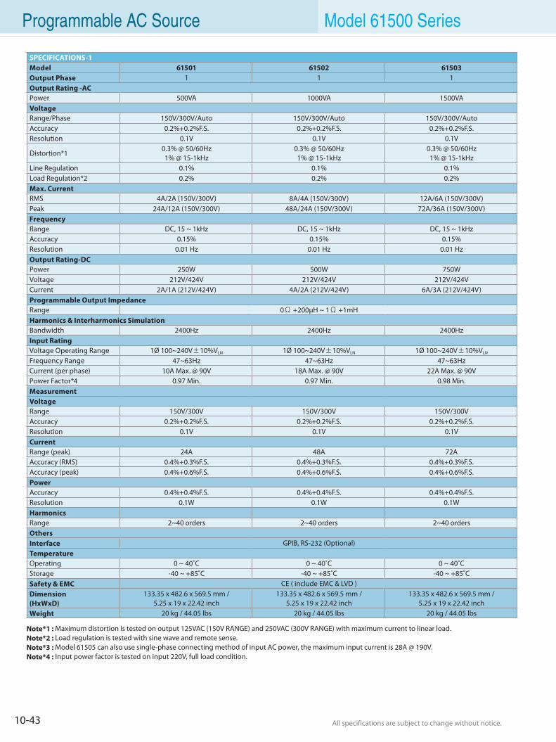
10-43 All specifications are subject to change without notice. All specifications are subject to change without notice.
Programmable AC Source Model 61500 Series
SPECIFICATIONS-1Model 61501 61502 61503Output Phase 1 1 1Output Rating -ACPower 500VA 1000VA 1500VAVoltageRange/Phase 150V/300V/Auto 150V/300V/Auto 150V/300V/AutoAccuracy 0.2%+0.2%F.S. 0.2%+0.2%F.S. 0.2%+0.2%F.S.Resolution 0.1V 0.1V 0.1V
Distortion*10.3% @ 50/60Hz1% @ 15-1kHz
0.3% @ 50/60Hz1% @ 15-1kHz
0.3% @ 50/60Hz1% @ 15-1kHz
Line Regulation 0.1% 0.1% 0.1%Load Regulation*2 0.2% 0.2% 0.2%Max. CurrentRMS 4A/2A (150V/300V) 8A/4A (150V/300V) 12A/6A (150V/300V)Peak 24A/12A (150V/300V) 48A/24A (150V/300V) 72A/36A (150V/300V)FrequencyRange DC, 15 ~ 1kHz DC, 15 ~ 1kHz DC, 15 ~ 1kHzAccuracy 0.15% 0.15% 0.15%Resolution 0.01 Hz 0.01 Hz 0.01 HzOutput Rating-DCPower 250W 500W 750WVoltage 212V/424V 212V/424V 212V/424VCurrent 2A/1A (212V/424V) 4A/2A (212V/424V) 6A/3A (212V/424V)Programmable Output ImpedanceRange 0Ω +200µH ~ 1Ω +1mHHarmonics & Interharmonics SimulationBandwidth 2400Hz 2400Hz 2400HzInput RatingVoltage Operating Range 1Ø 100~240V±10%VLN 1Ø 100~240V±10%VLN 1Ø 100~240V±10%VLN
Frequency Range 47~63Hz 47~63Hz 47~63HzCurrent (per phase) 10A Max. @ 90V 18A Max. @ 90V 22A Max. @ 90VPower Factor*4 0.97 Min. 0.97 Min. 0.98 Min.MeasurementVoltageRange 150V/300V 150V/300V 150V/300VAccuracy 0.2%+0.2%F.S. 0.2%+0.2%F.S. 0.2%+0.2%F.S.Resolution 0.1V 0.1V 0.1VCurrentRange (peak) 24A 48A 72AAccuracy (RMS) 0.4%+0.3%F.S. 0.4%+0.3%F.S. 0.4%+0.3%F.S.Accuracy (peak) 0.4%+0.6%F.S. 0.4%+0.6%F.S. 0.4%+0.6%F.S.PowerAccuracy 0.4%+0.4%F.S. 0.4%+0.4%F.S. 0.4%+0.4%F.S.Resolution 0.1W 0.1W 0.1WHarmonicsRange 2~40 orders 2~40 orders 2~40 ordersOthersInterface GPIB, RS-232 (Optional)TemperatureOperating 0 ~ 40˚C 0 ~ 40˚C 0 ~ 40˚CStorage -40 ~ +85˚C -40 ~ +85˚C -40 ~ +85˚CSafety & EMC CE ( include EMC & LVD )Dimension(HxWxD)
133.35 x 482.6 x 569.5 mm /5.25 x 19 x 22.42 inch
133.35 x 482.6 x 569.5 mm /5.25 x 19 x 22.42 inch
133.35 x 482.6 x 569.5 mm /5.25 x 19 x 22.42 inch
Weight 20 kg / 44.05 lbs 20 kg / 44.05 lbs 20 kg / 44.05 lbs
Note*1 : Maximum distortion is tested on output 125VAC (150V RANGE) and 250VAC (300V RANGE) with maximum current to linear load.Note*2 : Load regulation is tested with sine wave and remote sense.Note*3 : Model 61505 can also use single-phase connecting method of input AC power, the maximum input current is 28A @ 190V.Note*4 : Input power factor is tested on input 220V, full load condition.
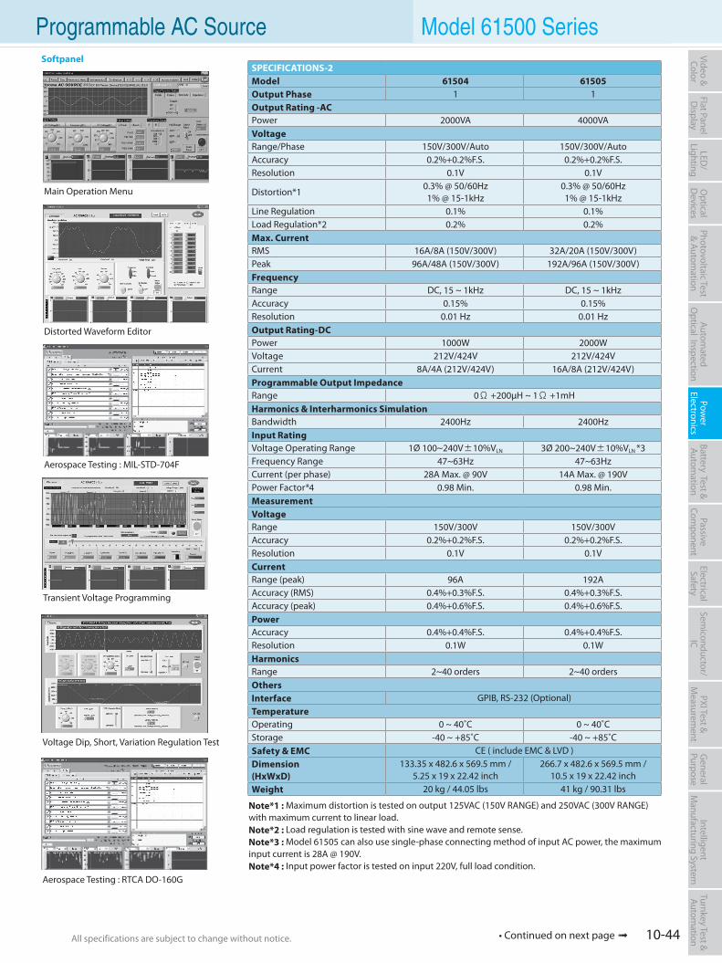
10-44All specifications are subject to change without notice. All specifications are subject to change without notice.
Flat PanelD
isplayPow
er Electronics
Electrical Safety
General
PurposePassive
Component
Semiconductor/
ICBattery Test & Autom
ationAutom
atedO
ptical Inspection Photovoltaic Test
& Automation
PXI Test &
Measurem
ent Video & Color
LED/
LightingO
ptical D
evicesIntelligent
Manufacturing System
Turnkey Test & Autom
ation
• Continued on next page
Programmable AC Source Model 61500 Series
SPECIFICATIONS-2Model 61504 61505Output Phase 1 1Output Rating -ACPower 2000VA 4000VAVoltageRange/Phase 150V/300V/Auto 150V/300V/AutoAccuracy 0.2%+0.2%F.S. 0.2%+0.2%F.S.Resolution 0.1V 0.1V
Distortion*10.3% @ 50/60Hz1% @ 15-1kHz
0.3% @ 50/60Hz1% @ 15-1kHz
Line Regulation 0.1% 0.1%Load Regulation*2 0.2% 0.2%Max. CurrentRMS 16A/8A (150V/300V) 32A/20A (150V/300V)Peak 96A/48A (150V/300V) 192A/96A (150V/300V)FrequencyRange DC, 15 ~ 1kHz DC, 15 ~ 1kHzAccuracy 0.15% 0.15%Resolution 0.01 Hz 0.01 HzOutput Rating-DCPower 1000W 2000WVoltage 212V/424V 212V/424VCurrent 8A/4A (212V/424V) 16A/8A (212V/424V)Programmable Output ImpedanceRange 0Ω +200µH ~ 1Ω +1mHHarmonics & Interharmonics SimulationBandwidth 2400Hz 2400HzInput RatingVoltage Operating Range 1Ø 100~240V±10%VLN 3Ø 200~240V±10%VLN *3Frequency Range 47~63Hz 47~63HzCurrent (per phase) 28A Max. @ 90V 14A Max. @ 190VPower Factor*4 0.98 Min. 0.98 Min.MeasurementVoltageRange 150V/300V 150V/300VAccuracy 0.2%+0.2%F.S. 0.2%+0.2%F.S.Resolution 0.1V 0.1VCurrentRange (peak) 96A 192AAccuracy (RMS) 0.4%+0.3%F.S. 0.4%+0.3%F.S.Accuracy (peak) 0.4%+0.6%F.S. 0.4%+0.6%F.S.PowerAccuracy 0.4%+0.4%F.S. 0.4%+0.4%F.S.Resolution 0.1W 0.1WHarmonicsRange 2~40 orders 2~40 ordersOthersInterface GPIB, RS-232 (Optional)TemperatureOperating 0 ~ 40˚C 0 ~ 40˚CStorage -40 ~ +85˚C -40 ~ +85˚CSafety & EMC CE ( include EMC & LVD )Dimension(HxWxD)
133.35 x 482.6 x 569.5 mm /5.25 x 19 x 22.42 inch
266.7 x 482.6 x 569.5 mm /10.5 x 19 x 22.42 inch
Weight 20 kg / 44.05 lbs 41 kg / 90.31 lbs
Transient Voltage Programming
Distorted Waveform Editor
Voltage Dip, Short, Variation Regulation Test
Main Operation Menu
Aerospace Testing : MIL-STD-704F
Aerospace Testing : RTCA DO-160G
Softpanel
Note*1 : Maximum distortion is tested on output 125VAC (150V RANGE) and 250VAC (300V RANGE) with maximum current to linear load.Note*2 : Load regulation is tested with sine wave and remote sense.Note*3 : Model 61505 can also use single-phase connecting method of input AC power, the maximum input current is 28A @ 190V.Note*4 : Input power factor is tested on input 220V, full load condition.
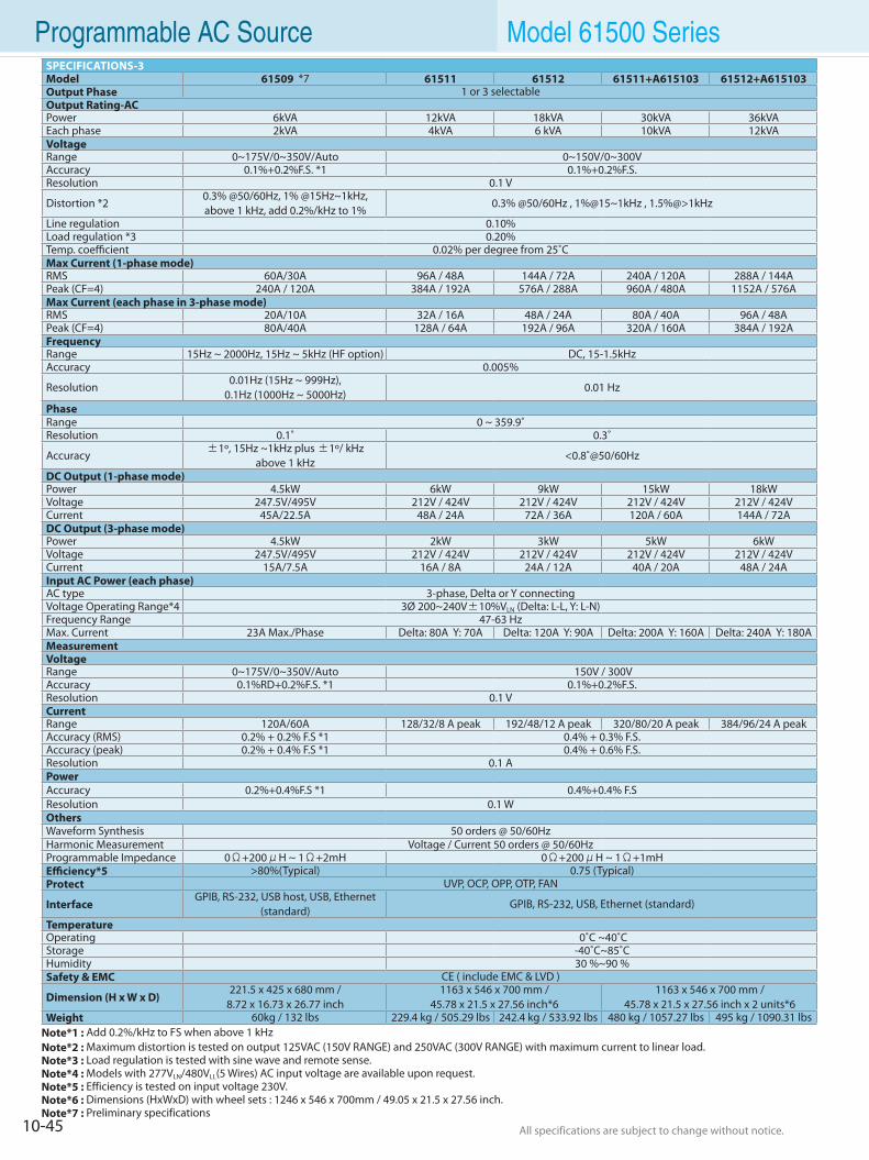
10-45 All specifications are subject to change without notice. All specifications are subject to change without notice.
Programmable AC Source Model 61500 SeriesSPECIFICATIONS-3Model 61509 *7 61511 61512 61511+A615103 61512+A615103Output Phase 1 or 3 selectableOutput Rating-ACPower 6kVA 12kVA 18kVA 30kVA 36kVAEach phase 2kVA 4kVA 6 kVA 10kVA 12kVAVoltageRange 0~175V/0~350V/Auto 0~150V/0~300VAccuracy 0.1%+0.2%F.S. *1 0.1%+0.2%F.S.Resolution 0.1 V
Distortion *20.3% @50/60Hz, 1% @15Hz~1kHz,above 1 kHz, add 0.2%/kHz to 1%
0.3% @50/60Hz , 1%@15~1kHz , 1.5%@>1kHz
Line regulation 0.10% Load regulation *3 0.20% Temp. coefficient 0.02% per degree from 25˚CMax Current (1-phase mode)RMS 60A/30A 96A / 48A 144A / 72A 240A / 120A 288A / 144APeak (CF=4) 240A / 120A 384A / 192A 576A / 288A 960A / 480A 1152A / 576AMax Current (each phase in 3-phase mode)RMS 20A/10A 32A / 16A 48A / 24A 80A / 40A 96A / 48APeak (CF=4) 80A/40A 128A / 64A 192A / 96A 320A / 160A 384A / 192AFrequencyRange 15Hz ~ 2000Hz, 15Hz ~ 5kHz (HF option) DC, 15-1.5kHzAccuracy 0.005%
Resolution0.01Hz (15Hz ~ 999Hz),
0.1Hz (1000Hz ~ 5000Hz)0.01 Hz
PhaseRange 0 ~ 359.9˚Resolution 0.1˚ 0.3˚
Accuracy ±1º, 15Hz ~1kHz plus ±1º/ kHz above 1 kHz
<0.8˚@50/60Hz
DC Output (1-phase mode)Power 4.5kW 6kW 9kW 15kW 18kWVoltage 247.5V/495V 212V / 424V 212V / 424V 212V / 424V 212V / 424VCurrent 45A/22.5A 48A / 24A 72A / 36A 120A / 60A 144A / 72ADC Output (3-phase mode)Power 4.5kW 2kW 3kW 5kW 6kWVoltage 247.5V/495V 212V / 424V 212V / 424V 212V / 424V 212V / 424VCurrent 15A/7.5A 16A / 8A 24A / 12A 40A / 20A 48A / 24AInput AC Power (each phase)AC type 3-phase, Delta or Y connectingVoltage Operating Range*4 3Ø 200~240V±10%VLN (Delta: L-L, Y: L-N)Frequency Range 47-63 HzMax. Current 23A Max./Phase Delta: 80A Y: 70A Delta: 120A Y: 90A Delta: 200A Y: 160A Delta: 240A Y: 180AMeasurementVoltageRange 0~175V/0~350V/Auto 150V / 300VAccuracy 0.1%RD+0.2%F.S. *1 0.1%+0.2%F.S.Resolution 0.1 VCurrentRange 120A/60A 128/32/8 A peak 192/48/12 A peak 320/80/20 A peak 384/96/24 A peakAccuracy (RMS) 0.2% + 0.2% F.S *1 0.4% + 0.3% F.S.Accuracy (peak) 0.2% + 0.4% F.S *1 0.4% + 0.6% F.S.Resolution 0.1 APowerAccuracy 0.2%+0.4%F.S *1 0.4%+0.4% F.SResolution 0.1 WOthersWaveform Synthesis 50 orders @ 50/60HzHarmonic Measurement Voltage / Current 50 orders @ 50/60HzProgrammable Impedance 0Ω+200μH ~ 1Ω+2mH 0Ω+200μH ~ 1Ω+1mHEfficiency*5 >80%(Typical) 0.75 (Typical)Protect UVP, OCP, OPP, OTP, FAN
InterfaceGPIB, RS-232, USB host, USB, Ethernet
(standard) GPIB, RS-232, USB, Ethernet (standard)
TemperatureOperating 0˚C ~40˚C Storage -40˚C~85˚C Humidity 30 %~90 %Safety & EMC CE ( include EMC & LVD )
Dimension (H x W x D)221.5 x 425 x 680 mm /
8.72 x 16.73 x 26.77 inch1163 x 546 x 700 mm /
45.78 x 21.5 x 27.56 inch*61163 x 546 x 700 mm /
45.78 x 21.5 x 27.56 inch x 2 units*6Weight 60kg / 132 lbs 229.4 kg / 505.29 lbs 242.4 kg / 533.92 lbs 480 kg / 1057.27 lbs 495 kg / 1090.31 lbs
Note*1 : Add 0.2%/kHz to FS when above 1 kHzNote*2 : Maximum distortion is tested on output 125VAC (150V RANGE) and 250VAC (300V RANGE) with maximum current to linear load.Note*3 : Load regulation is tested with sine wave and remote sense.Note*4 : Models with 277VLN/480VLL(5 Wires) AC input voltage are available upon request.Note*5 : Efficiency is tested on input voltage 230V.Note*6 : Dimensions (HxWxD) with wheel sets : 1246 x 546 x 700mm / 49.05 x 21.5 x 27.56 inch.Note*7 : Preliminary specifications
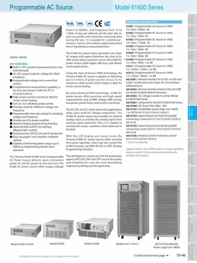
10-46All specifications are subject to change without notice. All specifications are subject to change without notice.
Flat PanelD
isplayPow
er Electronics
Electrical Safety
General
PurposePassive
Component
Semiconductor/
ICBattery Test & Autom
ationAutom
atedO
ptical Inspection Photovoltaic Test
& Automation
PXI Test &
Measurem
ent Video & Color
LED/
LightingO
ptical D
evicesIntelligent
Manufacturing System
Turnkey Test & Autom
ation Programmable AC Source Model 61600 Series
500VA~90kVA
KEY FEATURES Built-in PFC, provide input power factor over 0.98 (full load) AC+DC output mode for voltage DC offset
simulation Programmable voltage and current limit
setting Comprehensive measurement capability, V,
Hz, Irms, Ipk, Iinrush, P, VAR, VA, PF, CF of current and etc. High output current crest factor, ideal for
inrush current testing Turn on, turn off phase angle control One-key recall for 9 different voltage and
frequency Programmable slew rate setting for changing voltage and frequency Analog input for power amplifier Optional Analog programming interface Optional GPIB and RS-232 interface (Model 61601~61605) Full protection: OP, OC, OV and OT protection Easy use graphic user interface: softpanel
(option) Capable of delivering power output up to 90KVA by implementing Master-Slave
operation
The Chroma Model 61600 series Programmable AC Power Source delivers pure, instrument grade AC and DC power at very low cost. The 61600 AC power source offers output voltage
from 0 to 300VAC, and frequency from 15 to 1.5kHz. A easy-use software can let users edit an auto-run profile and record the measuring data during the test. It is suitable for commercial , avionics, marine, and military applications from bench-top testing to mass productions.
The 61600 AC power source generates very clean AC output with typical distortion less than 0.3%. With power factor correction circuit, the 61600 AC power source yields higher efficiency and deliver more output power .
Using the state-of-the-art PWM technology, the Chroma 61600 AC source is capable of delivering up to 6 t imes of peak current versus to its maximum rated current which makes it ideal for inrush current testing.
By using advanced DSP technology, 61600 AC power source offers precision and high speed measurements such as RMS voltage, RMS current, true power, power factor, and current crest factor.
The AC+DC and DC mode extend the applications when users need DC voltage component. The 61600 AC power source also provides an external analog input, to amplify the analog signal from arbitrary signal generator. Thus, it is capable to simulate the unique waveform which observed in the field.
With the LCD display and rotar y knob, the Chroma 61600 AC power source offers versatile front panel operation. Users may also control the 61600 remotely via GPIB, RS-232 or APG (Analog Programming) interface.
The self-diagnosis routine and the full protections against OPP, OCP, OVP and OTP ensure the quality and reliability for even the most demanding engineering testing and ATE application.
61601 : Programmable AC Source 0~300V, 15~1kHz / 500VA, 1Ø61602 : Programmable AC Source 0~300V, 15~1kHz / 1kVA, 1Ø61603 : Programmable AC Source 0~300V, 15~1kHz / 1.5kVA, 1Ø61604 : Programmable AC Source 0~300V, 15~1kHz / 2kVA, 1Ø61605 : Programmable AC Source 0~300V, 15~1kHz / 4kVA, 1Ø61609 : Programmable AC Source 0~350V, 15~1kHz / 4kVA, 1 or 3Ø61611 : Programmable AC Source 0~300V, 15~1.5kHz / 12kVA, 1 or 3Ø61612 : Programmable AC Source 0~300V, 15~1.5kHz / 18kVA, 1 or 3ØA615001 : Remote Interface for 61501~61505 and 61601~61605 (External V Input, RS-232 Interface, GPIB Interface)A615002 : Remote interface board (LAN and USB)for Model 61500/61600/61700 SeriesA615003 : AC voltage transform unit for Model 61500/61600 SeriesA615007 : Softpanel for Model 61500/61600 SeriesA615008 : DC Noise Filter (Max. 16A)A615103 : Parallelable power stage unit 18kVA, 1 or 3Ø, for 61511/61512/61611/61612A615104 : Input/Output terminals for parallel connecting 2 units of 61511/61512/61611/61612/ A615103A615105 : Input/Output terminals for parallel connecting 3 units of 61511/61512/61611/61612/ A615103A615106 : Reverse Current Protection unit for 61511/61512/61611/61612* Call for availability
Support higher than 300V output voltage capability, please contact Chroma sales representative for detailed information.
ORDERING INFORMATION
Model 61605 Model 61609Model 61605~61604 Model 61611, 61612 A615103 ParallelablePower stage Unit 18KVA
*
• Continued on next page
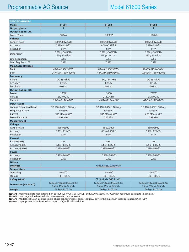
10-47 All specifications are subject to change without notice. All specifications are subject to change without notice.
Programmable AC Source Model 61600 Series
SPECIFICATIONS-1Model 61601 61602 61603Output phase 1 1 1 Output Rating - ACPower/Phase 500VA 1000VA 1500VA VoltageRange/Phase 150V/300V/Auto 150V/300V/Auto 150V/300V/AutoAccuracy 0.2%+0.2%F.S. 0.2%+0.2%F.S. 0.2%+0.2%F.S. Resolution 0.1V 0.1V 0.1V
Distortion *10.3% @ 50/60Hz 1% @ 15~1kHz
0.3% @ 50/60Hz 1% @ 15~1kHz
0.3% @ 50/60Hz 1% @ 15~1kHz
Line Regulation 0.1% 0.1% 0.1% Load Regulation *2 0.2% 0.2% 0.2%Max. Current/PhaseRMS 4A/2A (150V/300V) 8A/4A (150V/300V) 12A/6A (150V/300V) peak 24A/12A (150V/300V) 48A/24A (150V/300V) 72A/36A (150V/300V) FrequencyRange DC, 15~1kHz DC, 15~1kHz DC, 15~1kHz Accuracy 0.15% 0.15% 0.15% Resolution 0.01 Hz 0.01 Hz 0.01 HzOutput Rating - DCPower 250W 500W 750W Voltage 212V/424V 212V/424V 212V/424V Current 2A/1A (212V/424V) 4A/2A (212V/424V) 6A/3A (212V/424V) Input RatingVoltage Operating Range 1Ø 100~240V±10%VLN 1Ø 100~240V±10%VLN 1Ø 100~240V±10%VLN Frequency Range 47~63Hz 47~63Hz 47~63Hz Current 10A Max. @ 90V 18A Max. @ 90V 22A Max. @ 90V Power Factor *4 0.97 Min. 0.97 Min. 0.98 Min. Measurement VoltageRange/Phase 150V/300V 150V/300V 150V/300V Accuracy 0.2%+0.2%F.S. 0.2%+0.2%F.S. 0.2%+0.2%F.S. Resolution 0.1V 0.1V 0.1V CurrentRange (peak) 24A 48A 72A Accuracy (RMS) 0.4%+0.3%F.S. 0.4%+0.3%F.S. 0.4%+0.3%F.S. Accuracy (peak) 0.4%+0.6%F.S. 0.4%+0.6%F.S. 0.4%+0.6%F.S. PowerAccuracy 0.4%+0.4%F.S. 0.4%+0.4%F.S. 0.4%+0.4%F.S. Resolution 0.1W 0.1W 0.1W OthersInterface GPIB, RS-232 (Optional)TemperatureOperating 0~40˚C 0~40˚C 0~40˚C Storage -40 ~ +85˚C -40 ~ +85˚C -40 ~ +85˚CSafety & EMC CE ( include EMC & LVD )
Dimension (H x W x D)133.35 x 482.6 x 569.5 mm /
5.25 x 19 x 22.42 inch133.35 x 482.6 x 569.5 mm /
5.25 x 19 x 22.42 inch133.35 x 482.6 x 569.5 mm /
5.25 x 19 x 22.42 inchWeight 20 kg / 44.05 lbs 20 kg / 44.05 lbs 20 kg / 44.05 lbs
Note*1 : Maximum distortion is tested on output 125VAC (150V RANGE) and 250VAC (300V RANGE) with maximum current to linear load.Note*2 : Load regulation is tested with sinewave and remote sense.Note*3 : Model 61605 can also use single-phase connecting method of input AC power, the maximum input current is 28A @ 190V.Note*4 : Input power factor is tested on input 220V, full load condition.
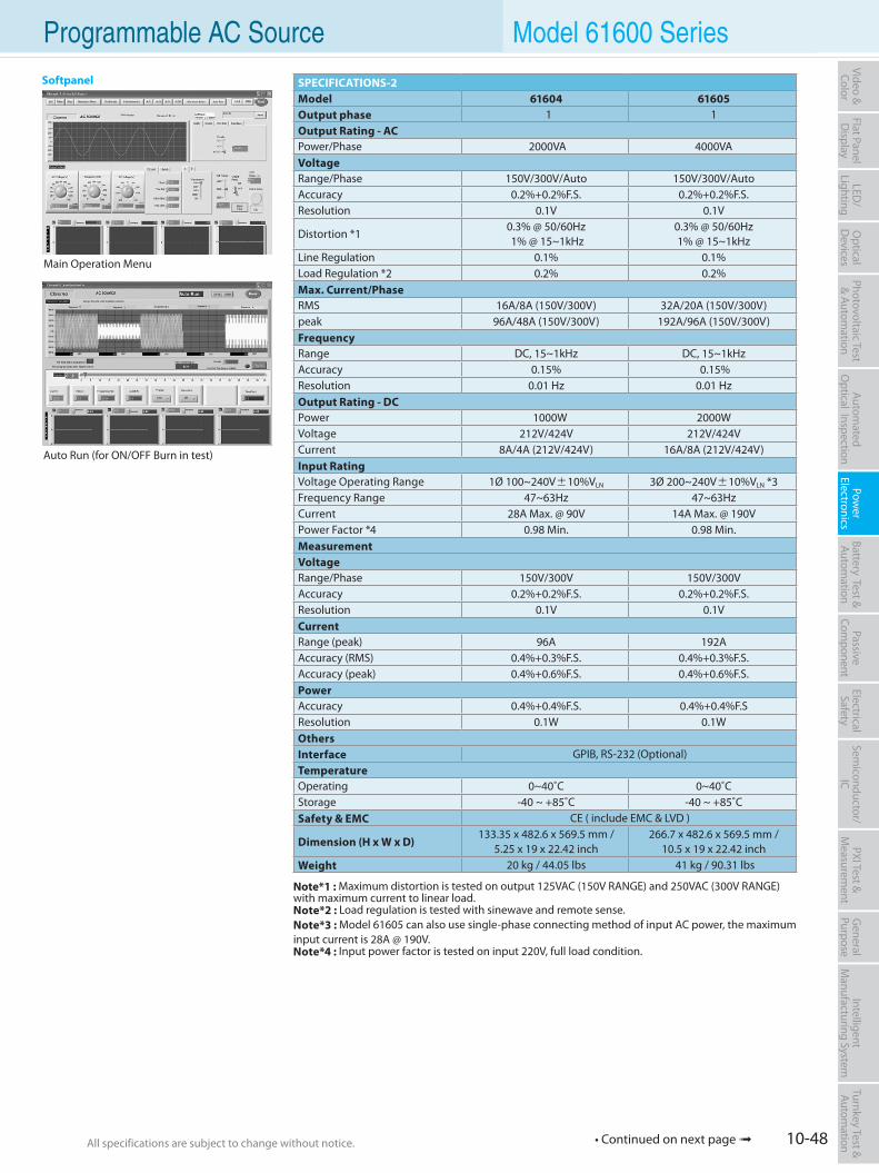
10-48All specifications are subject to change without notice. All specifications are subject to change without notice.
Flat PanelD
isplayPow
er Electronics
Electrical Safety
General
PurposePassive
Component
Semiconductor/
ICBattery Test & Autom
ationAutom
atedO
ptical Inspection Photovoltaic Test
& Automation
PXI Test &
Measurem
ent Video & Color
LED/
LightingO
ptical D
evicesIntelligent
Manufacturing System
Turnkey Test & Autom
ation Programmable AC Source Model 61600 Series
SPECIFICATIONS-2Model 61604 61605Output phase 1 1Output Rating - ACPower/Phase 2000VA 4000VA VoltageRange/Phase 150V/300V/Auto 150V/300V/Auto Accuracy 0.2%+0.2%F.S. 0.2%+0.2%F.S. Resolution 0.1V 0.1V
Distortion *10.3% @ 50/60Hz 1% @ 15~1kHz
0.3% @ 50/60Hz 1% @ 15~1kHz
Line Regulation 0.1% 0.1% Load Regulation *2 0.2% 0.2% Max. Current/PhaseRMS 16A/8A (150V/300V) 32A/20A (150V/300V)peak 96A/48A (150V/300V) 192A/96A (150V/300V) FrequencyRange DC, 15~1kHz DC, 15~1kHz Accuracy 0.15% 0.15% Resolution 0.01 Hz 0.01 HzOutput Rating - DCPower 1000W 2000W Voltage 212V/424V 212V/424VCurrent 8A/4A (212V/424V) 16A/8A (212V/424V) Input RatingVoltage Operating Range 1Ø 100~240V±10%VLN 3Ø 200~240V±10%VLN *3Frequency Range 47~63Hz 47~63Hz Current 28A Max. @ 90V 14A Max. @ 190V Power Factor *4 0.98 Min. 0.98 Min. Measurement VoltageRange/Phase 150V/300V 150V/300V Accuracy 0.2%+0.2%F.S. 0.2%+0.2%F.S. Resolution 0.1V 0.1V CurrentRange (peak) 96A 192A Accuracy (RMS) 0.4%+0.3%F.S. 0.4%+0.3%F.S. Accuracy (peak) 0.4%+0.6%F.S. 0.4%+0.6%F.S. PowerAccuracy 0.4%+0.4%F.S. 0.4%+0.4%F.S Resolution 0.1W 0.1W OthersInterface GPIB, RS-232 (Optional)TemperatureOperating 0~40˚C 0~40˚CStorage -40 ~ +85˚C -40 ~ +85˚CSafety & EMC CE ( include EMC & LVD )
Dimension (H x W x D)133.35 x 482.6 x 569.5 mm /
5.25 x 19 x 22.42 inch 266.7 x 482.6 x 569.5 mm /
10.5 x 19 x 22.42 inchWeight 20 kg / 44.05 lbs 41 kg / 90.31 lbs
Note*1 : Maximum distortion is tested on output 125VAC (150V RANGE) and 250VAC (300V RANGE) with maximum current to linear load.Note*2 : Load regulation is tested with sinewave and remote sense.Note*3 : Model 61605 can also use single-phase connecting method of input AC power, the maximum input current is 28A @ 190V.Note*4 : Input power factor is tested on input 220V, full load condition.
Main Operation Menu
Auto Run (for ON/OFF Burn in test)
Softpanel
• Continued on next page
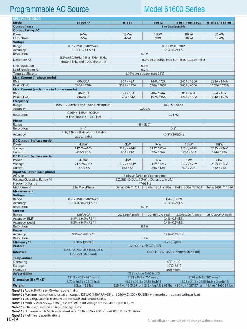
10-49 All specifications are subject to change without notice. All specifications are subject to change without notice.
Programmable AC Source Model 61600 SeriesSPECIFICATIONS-3Model 61609 *7 61611 61612 61611+A615103 61612+A615103Output Phase 1 or 3 selectableOutput Rating-ACPower 6kVA 12kVA 18kVA 30kVA 36kVAEach phase 2kVA 4kVA 6kVA 10kVA 12kVAVoltageRange 0~175V/0~350V/Auto 0~150V/0~300VAccuracy 0.1%+0.2%F.S. *1 0.1%+0.2%F.S.Resolution 0.1 V
Distortion *20.3% @50/60Hz, 1% @15Hz~1kHz,above 1 kHz, add 0.2%/kHz to 1%
0.3% @50/60Hz , 1%@15~1kHz , 1.5%@>1kHz
Line regulation 0.1% Load regulation *3 0.2% Temp. coefficient 0.02% per degree from 25˚CMax. Current (1-phase mode)RMS 60A/30A 96A / 48A 144A / 72A 240A / 120A 288A / 144APeak (CF=4) 240A / 120A 384A / 192A 576A / 288A 960A / 480A 1152A / 576AMax. Current (each phase in 3-phase mode)RMS 20A/10A 32A / 16A 48A / 24A 80A / 40A 96A / 48APeak (CF=4) 80A/40A 128A / 64A 192A / 96A 320A / 160A 384A / 192AFrequencyRange 15Hz ~ 2000Hz, 15Hz ~ 5kHz (HF option) DC, 15-1.5kHzAccuracy 0.005%
Resolution0.01Hz (15Hz ~ 999Hz),
0.1Hz (1000Hz ~ 5000Hz)0.01 Hz
PhaseRange 0 ~ 360˚Resolution 0.1˚ 0.3˚
Accuracy ±1º, 15Hz ~1kHz plus ±1º/ kHz above 1 kHz
<0.8˚@50/60Hz
DC Output (1-phase mode)Power 4.5kW 6kW 9kW 15kW 18kWVoltage 247.5V/495V 212V / 424V 212V / 424V 212V / 424V 212V / 424VCurrent 45A/22.5A 48A / 24A 72A / 36A 120A / 60A 144A / 72ADC Output (3-phase mode)Power 4.5kW 2kW 3kW 5kW 6kWVoltage 247.5V/495V 212V / 424V 212V / 424V 212V / 424V 212V / 424VCurrent 15A/7.5A 16A / 8A 24A / 12A 40A / 20A 48A / 24AInput AC Power (each phase)AC type 3-phase, Delta or Y connectingVoltage Operating Range *4 3Ø, 200~240V±10%VLN (Delta: L-L, Y: L-N)Frequency Range 47-63 HzMax. Current 23A Max./Phase Delta: 80A Y: 70A Delta: 120A Y: 90A Delta: 200A Y: 160A Delta: 240A Y: 180AMeasurementVoltageRange 0~175V/0~350V/Auto 150V / 300VAccuracy 0.1%RD+0.2%F.S. *1 0.1%+0.2%F.S.Resolution 0.1 VCurrentRange 120A/60A 128/32/8 A peak 192/48/12 A peak 320/80/20 A peak 384/96/24 A peakAccuracy (RMS) 0.2% + 0.2% F.S *1 0.4%+0.3%F.S.Accuracy (peak) 0.2% + 0.4% F.S *1 0.4%+0.6%F.S.Resolution 0.1 APowerAccuracy 0.2%+0.4%F.S *1 0.4%+0.4% F.SResolution 0.1 WEfficiency *5 >80%(Typical) 0.75 (Typical)Protect UVP, OCP, OPP, OTP, FAN
InterfaceGPIB, RS-232, USB host, USB,
Ethernet (standard) GPIB, RS-232, USB, Ethernet (Standard)
TemperatureOperating 0˚C~40˚C Storage -40˚C~85˚C Humidity 30%~90%Safety & EMC CE ( include EMC & LVD )
Dimension (H x W x D)221.5 x 425 x 680 mm /
8.72 x 16.73 x 26.77 inch1163 x 546 x 700 mm /
45.78 x 21.5 x 27.56 inch*51163 x 546 x 700 mm /
45.78 x 21.5 x 27.56 inch x 2 units*6Weight 60kg / 132 lbs 229.4 kg / 505.29 lbs 242.4 kg / 533.92 lbs 480 kg / 1057.27 lbs 495 kg / 1090.31 lbs
Note*1 : Add 0.2%/kHz to FS when above 1 kHzNote*2 : Maximum distortion is tested on output 125VAC (150V RANGE) and 250VAC (300V RANGE) with maximum current to linear load.Note*3 : Load regulation is tested with sine wave and remote sense.Note*4 : Models with 277VLN/480VLL(5 Wires) AC input voltage are available upon request.Note*5 : Efficiency is tested on input voltage 230V.Note*6 : Dimensions (HxWxD) with wheel sets : 1246 x 546 x 700mm / 49.05 x 21.5 x 27.56 inch.Note*7 : Preliminary specifications
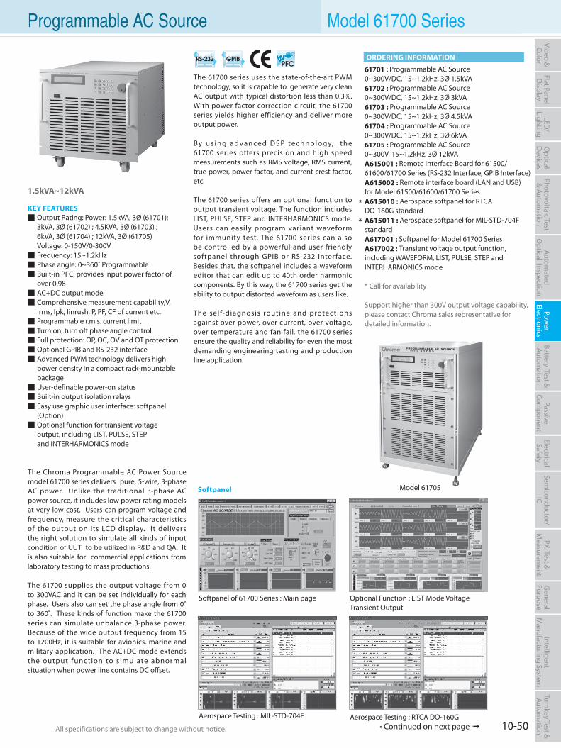
10-50All specifications are subject to change without notice. All specifications are subject to change without notice.
Flat PanelD
isplayPow
er Electronics
Electrical Safety
General
PurposePassive
Component
Semiconductor/
ICBattery Test & Autom
ationAutom
atedO
ptical Inspection Photovoltaic Test
& Automation
PXI Test &
Measurem
ent Video & Color
LED/
LightingO
ptical D
evicesIntelligent
Manufacturing System
Turnkey Test & Autom
ation Programmable AC Source Model 61700 Series
1.5kVA~12kVA
KEY FEATURES Output Rating: Power: 1.5kVA, 3Ø (61701);
3kVA, 3Ø (61702) ; 4.5KVA, 3Ø (61703) ; 6kVA, 3Ø (61704) ; 12kVA, 3Ø (61705) Voltage: 0-150V/0-300V Frequency: 15~1.2kHz Phase angle: 0~360˚ Programmable Built-in PFC, provides input power factor of
over 0.98 AC+DC output mode Comprehensive measurement capability,V,
Irms, Ipk, Iinrush, P, PF, CF of current etc. Programmable r.m.s. current limit Turn on, turn off phase angle control Full protection: OP, OC, OV and OT protection Optional GPIB and RS-232 interface Advanced PWM technology delivers high
power density in a compact rack-mountable package User-definable power-on status Built-in output isolation relays Easy use graphic user interface: softpanel
(Option) Optional function for transient voltage
output, including LIST, PULSE, STEP and INTERHARMONICS mode
The Chroma Programmable AC Power Source model 61700 series delivers pure, 5-wire, 3-phase AC power. Unlike the traditional 3-phase AC power source, it includes low power rating models at very low cost. Users can program voltage and frequency, measure the critical characteristics of the output on its LCD display. It delivers the right solution to simulate all kinds of input condition of UUT to be utilized in R&D and QA. It is also suitable for commercial applications from laboratory testing to mass productions.
The 61700 supplies the output voltage from 0 to 300VAC and it can be set individually for each phase. Users also can set the phase angle from 0˚ to 360˚. These kinds of function make the 61700 series can simulate unbalance 3-phase power. Because of the wide output frequency from 15 to 1200Hz, it is suitable for avionics, marine and military application. The AC+DC mode extends the output function to simulate abnormal situation when power line contains DC offset.
The 61700 series uses the state-of-the-art PWM technology, so it is capable to generate very clean AC output with typical distortion less than 0.3%. With power factor correction circuit, the 61700 series yields higher efficiency and deliver more output power.
B y u s i n g a d v a n ce d D S P te c h n o l o g y, t h e 61700 series offers precision and high speed measurements such as RMS voltage, RMS current, true power, power factor, and current crest factor, etc.
The 61700 series offers an optional function to output transient voltage. The function includes LIST, PULSE, STEP and INTERHARMONICS mode. Users can easily program variant waveform for immunity test. The 61700 series can also be controlled by a powerful and user friendly softpanel through GPIB or RS-232 interface. Besides that, the softpanel includes a waveform editor that can edit up to 40th order harmonic components. By this way, the 61700 series get the ability to output distorted waveform as users like.
The self-diagnosis routine and protections against over power, over current, over voltage, over temperature and fan fail, the 61700 series ensure the quality and reliability for even the most demanding engineering testing and production line application.
61701 : Programmable AC Source 0~300V/DC, 15~1.2kHz, 3Ø 1.5kVA61702 : Programmable AC Source 0~300V/DC, 15~1.2kHz, 3Ø 3kVA61703 : Programmable AC Source 0~300V/DC, 15~1.2kHz, 3Ø 4.5kVA61704 : Programmable AC Source 0~300V/DC, 15~1.2kHz, 3Ø 6kVA61705 : Programmable AC Source 0~300V, 15~1.2kHz, 3Ø 12kVAA615001 : Remote Interface Board for 61500/ 61600/61700 Series (RS-232 Interface, GPIB Interface)A615002 : Remote interface board (LAN and USB)for Model 61500/61600/61700 SeriesA615010 : Aerospace softpanel for RTCADO-160G standardA615011 : Aerospace softpanel for MIL-STD-704F standardA617001 : Softpanel for Model 61700 SeriesA617002 : Transient voltage output function, including WAVEFORM, LIST, PULSE, STEP and INTERHARMONICS mode
* Call for availability
Support higher than 300V output voltage capability, please contact Chroma sales representative for detailed information.
*
*
Softpanel of 61700 Series : Main page
Model 61705
Aerospace Testing : MIL-STD-704F Aerospace Testing : RTCA DO-160G
Optional Function : LIST Mode Voltage Transient Output
ORDERING INFORMATION
Softpanel
• Continued on next page
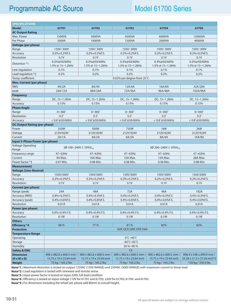
10-51 All specifications are subject to change without notice. All specifications are subject to change without notice.
Note*1 : Maximum distortion is tested on output 125VAC (150V RANGE) and 250VAC (300V RANGE) with maximum current to linear load.Note*2 : Load regulation is tested with sinewave and remote sense.Note*3 : Input power factor is tested on input 220V, full load conditionNote*4 : Efficiency is tested on input voltage 110V for 61701 and 61702, 220V for 61703, 61704 and 61705.Note*5 : For dimension including the wheel set, please add 80mm to overall height.
SPECIFICATIONSModel 61701 61702 61703 61704 61705AC Output Rating Max. Power 1500VA 3000VA 4500VA 6000VA 12000VAPer Phase 500VA 1000VA 1500VA 2000VA 4000VAVoltage (per phase)Range 150V/ 300V 150V/ 300V 150V/ 300V 150V/ 300V 150V/ 300VAccuracy 0.2%+0.2%F.S. 0.2%+0.2%F.S. 0.2%+0.2%F.S. 0.2%+0.2%F.S. 0.2%+0.2%F.S.Resolution 0.1V 0.1V 0.1V 0.1V 0.1V
Distortion *10.3%@50/60Hz
1.5% @ 15~1.2kHz0.3%@50/60Hz
1.5% @ 15~1.2kHz0.3%@50/60Hz
1.5% @ 15~1.2kHz0.3%@50/60Hz
1.5% @ 15~1.2kHz0.3%@50/60Hz
1.5% @ 15~1.2kHzLine regulation 0.1% 0.1% 0.1% 0.1% 0.1%Load regulation *2 0.2% 0.2% 0.2% 0.2% 0.2%Temp. coefficient 0.02% per degree from 25˚CMax. Current (per phase)RMS 4A/2A 8A/4A 12A/6A 16A/8A 32A/20Apeak 24A/12A 48A/24A 72A/36A 96A/48A 192A/96AFrequencyRange DC, 15~1.2kHz DC, 15~1.2kHz DC, 15~1.2kHz DC, 15~1.2kHz DC, 15~1.2kHzAccuracy 0.15% 0.15% 0.15% 0.15% 0.15%Phase AngleRange 0~360˚ 0~360˚ 0~360˚ 0~360˚ 0~360˚Resolution 0.3˚ 0.3˚ 0.3˚ 0.3˚ 0.3˚Accuracy < 0.8˚@50/60Hz < 0.8˚@50/60Hz < 0.8˚@50/60Hz < 0.8˚@50/60Hz < 0.8˚@50/60HzDC Output Rating (per phase)Power 250W 500W 750W 1kW 2kWVoltage 212V/424V 212V/424V 212V/424V 212V/424V 212V/424VCurrent 2A/1A 4A/2A 6A/3A 8A/4A 16A/8AInput 3-Phase Power (per phase)Voltage Operating Range
3Ø 100~240V±10%VLN 3Ø 200~240V±10%VLN
Frequency range 47~63Hz 47~63Hz 47~63Hz 47~63Hz 47~63HzCurrent 9A Max. 16A Max. 10A Max. 14A Max. 28A Max.Power factor *3 0.97 Min. 0.98 Min. 0.98 Min. 0.98 Min. 0.98 MinMeasurementVoltage (Line-Neutral)Range 150V/300V 150V/300V 150V/300V 150V/300V 150V/300VAccuracy 0.2%+0.2%F.S. 0.2%+0.2%F.S. 0.2%+0.2%F.S. 0.2%+0.2%F.S. 0.2%+0.2%F.S.Resolution 0.1V 0.1V 0.1V 0.1V 0.1VCurrent (per phase)Range (peak) 24A 48A 72A 96A 192AAccuracy (RMS) 0.4%+0.3%F.S. 0.4%+0.3%F.S. 0.4%+0.3%F.S. 0.4%+0.3%F.S. 0.4%+0.3%F.S.Accuracy (peak) 0.4%+0.6%F.S. 0.4%+0.6%F.S. 0.4%+0.6%F.S. 0.4%+0.6%F.S. 0.4%+0.6%F.S.Resolution 0.01A 0.01A 0.01A 0.01A 0.01APower (per phase)Accuracy 0.4%+0.4% F.S. 0.4%+0.4% F.S. 0.4%+0.4% F.S. 0.4%+0.4% F.S. 0.4%+0.4% F.S.Resolution 0.1W 0.1W 0.1W 0.1W 0.1WOthersEfficiency *4 68 % 77 % 81 % 82% 82%Protection UVP, OCP, OPP, OTP, FANTemperature RangeOperating 0˚C~40˚CStorage -40˚C~85˚CHumidity 30 %~90 %Safety & EMC CEDimension (H x W x D)
400 x 482.6 x 600.5 mm /15.75 x 19 x 23.64 inch
400 x 482.6 x 600.5 mm /15.75 x 19 x 23.64 inch
400 x 482.6 x 600.5 mm /15.75 x 19 x 23.64 inch
400 x 482.6 x 600.5 mm /15.75 x 19 x 23.64 inch
896.4 x 546 x 699.9 mm /35.28 x 21.5 x 27.56 inch*5
Weight 75 kg / 165.2 lbs 75 kg / 165.2 lbs 75 kg / 165.2 lbs 75 kg / 165.2 lbs 150 kg / 330.4 lbs
Programmable AC Source Model 61700 Series
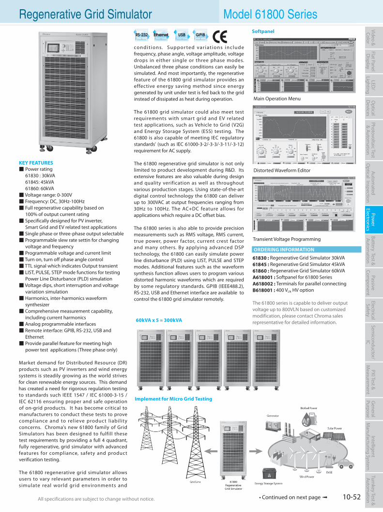
10-52All specifications are subject to change without notice. All specifications are subject to change without notice.
Flat PanelD
isplayPow
er Electronics
Electrical Safety
General
PurposePassive
Component
Semiconductor/
ICBattery Test & Autom
ationAutom
atedO
ptical Inspection Photovoltaic Test
& Automation
PXI Test &
Measurem
ent Video & Color
LED/
LightingO
ptical D
evicesIntelligent
Manufacturing System
Turnkey Test & Autom
ation Regenerative Grid Simulator Model 61800 Series
KEY FEATURES Power rating 61830 : 30kVA 61845: 45kVA 61860: 60kVA Voltage range: 0-300V Frequency: DC, 30Hz-100Hz Full regenerative capability based on 100% of output current rating Specifically designed for PV inverter, Smart Grid and EV related test applications Single phase or three-phase output selectable Programmable slew rate settin for changing
voltage and frequency Programmable voltage and current limit Turn on, turn off phase angle control TTL signal which indicates Output transient LIST, PULSE, STEP mode functions for testing
Power Line Disturbance (PLD) simulation Voltage dips, short interruption and voltage
variation simulation Harmonics, inter-harmonics waveform
synthesizer Comprehensive measurement capability,
including current harmonics Analog programmable interfaces Remote interface: GPIB, RS-232, USB and
Ethernet Provide parallel feature for meeting high power test applications (Three phase only)
Market demand for Distributed Resource (DR) products such as PV inverters and wind energy systems is steadily growing as the world strives for clean renewable energy sources. This demand has created a need for rigorous regulation testing to standards such IEEE 1547 / IEC 61000-3-15 / IEC 62116 ensuring proper and safe operation of on-grid products. It has become critical to manufacturers to conduct these tests to prove compliance and to relieve product l iability concerns. Chroma's new 61800 family of Grid Simulators has been designed to fulfill these test requirements by providing a full 4 quadrant, fully regenerative, grid simulator with advanced features for compliance, safety and product verification testing.
The 61800 regenerative grid simulator allows users to vary relevant parameters in order to simulate real world grid environments and
condit ions. Suppor ted var iat ions inc lude frequency, phase angle, voltage amplitude, voltage drops in either single or three phase modes. Unbalanced three phase conditions can easily be simulated. And most importantly, the regenerative feature of the 61800 grid simulator provides an effective energy saving method since energy generated by unit under test is fed back to the grid instead of dissipated as heat during operation.
The 61800 grid simulator could also meet test requirements with smart grid and EV related test applications, such as Vehicle to Grid (V2G) and Energy Storage System (ESS) testing. The 61800 is also capable of meeting IEC regulatory standards' (such as IEC 61000-3-2/-3-3/-3-11/-3-12)requirement for AC supply.
The 61800 regenerative grid simulator is not only limited to product development during R&D. Its extensive features are also valuable during design and quality verification as well as throughout various production stages. Using state-of-the-art digital control technology the 61800 can deliver up to 300VAC at output frequencies ranging from 30Hz to 100Hz. The AC+DC feature allows for applications which require a DC offset bias.
The 61800 series is also able to provide precision measurements such as RMS voltage, RMS current, true power, power factor, current crest factor and many others. By applying advanced DSP technology, the 61800 can easily simulate power line disturbance (PLD) using LIST, PULSE and STEP modes. Additional features such as the waveform synthesis function allows users to program various distorted harmonic waveforms which are required by some regulatory standards. GPIB (IEEE488.2), RS-232, USB and Ethernet interface are available to control the 61800 grid simulator remotely.
61830 : Regenerative Grid Simulator 30kVA61845 : Regenerative Grid Simulator 45kVA61860 : Regenerative Grid Simulator 60kVAA618001 : Softpanel for 61800 SeriesA618002 : Terminals for parallel connectingB618001 : 400 VLN HV option
The 61800 series is capable to deliver outputvoltage up to 800VLN based on customizedmodification, please contact Chroma salesrepresentative for detailed information.
Implement for Micro Grid Testing
60kVA x 5 = 300kVA
ORDERING INFORMATION
Transient Voltage Programming
Distorted Waveform Editor
Main Operation Menu
Softpanel
• Continued on next page
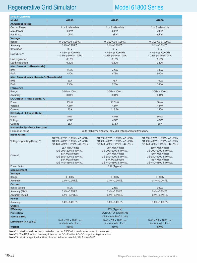
10-53 All specifications are subject to change without notice. All specifications are subject to change without notice.
Regenerative Grid Simulator Model 61800 Series
Note*1 : Maximum distortion is tested on output 250V with maximum current to linear loadNote*2 : The DC function is mainly intended as DC offset for AC+DC output voltage functionNote*3 : Must be specified at time of order. All inputs are L-L, 3Ø, 3 wire+GND
SPECIFICATIONSModel 61830 61845 61860AC Output Rating Output Phase 1 or 3 selectable 1 or 3 selectable 1 or 3 selectableMax. Power 30kVA 45kVA 60kVAPer Phase 10kVA 15kVA 20kVAVoltageRange 0~300VLN/0~520VLL 0~300VLN/0~520VLL 0~300VLN/0~520VLL
Accuracy 0.1%+0.2%F.S. 0.1%+0.2%F.S. 0.1%+0.2%F.S.Resolution 0.1V 0.1V 0.1V
Distortion *1 < 0.5% @ 50/60Hz< 0.8% @ 30Hz~100Hz
< 0.5% @ 50/60Hz< 0.8% @ 30Hz~100Hz
< 0.5% @ 50/60Hz< 0.8% @ 30Hz~100Hz
Line regulation 0.10% 0.10% 0.10%Load regulation 0.20% 0.20% 0.20%Max. Current (1-Phase Mode)RMS 150A 225A 300APeak 450A 675A 900AMax. Current (each phase in 3-Phase Mode)RMS 50A 75A 100APeak 150A 225A 300AFrequencyRange 30Hz ~ 100Hz 30Hz ~ 100Hz 30Hz ~ 100HzAccuracy 0.01% 0.01% 0.01%DC Output (1-Phase Mode) *2Power 15kW 22.5kW 30kWVoltage 424V 424V 424VCurrent 75A 112.5A 150ADC Output (3-Phase Mode)Power 5kW 7.5kW 10kWVoltage 424V 424V 424VCurrent 25A 37.5A 50AHarmonics Synthesis FunctionHarmonics range up to 50 harmonics order @ 50/60Hz fundamental frequencyInput Rating
Voltage Operating Range *33Ø 200~220V±10%VLL, 47~63Hz3Ø 380~400V±10%VLL, 47~63Hz 3Ø 440~480V±10%VLL, 47~63Hz
3Ø 200~220V±10%VLL, 47~63Hz3Ø 380~400V±10%VLL, 47~63Hz 3Ø 440~480V±10%VLL, 47~63Hz
3Ø 200~220V±10%VLL, 47~63Hz3Ø 380~400V±10%VLL, 47~63Hz 3Ø 440~480V±10%VLL, 47~63Hz
Current
125A Max./Phase (3Ø 200~220V±10%VLL)
65A Max./Phase (3Ø 380~400V±10%VLL)
58A Max./Phase (3Ø 440~480V±10%VLL)
190A Max./Phase (3Ø 200~220V±10%VLL)
100A Max./Phase (3Ø 380~400V±10%VLL)
87A Max./Phase (3Ø 440~480V±10%VLL)
250A Max./Phase (3Ø 200~220V±10%VLL)
130A Max./Phase (3Ø 380~400V±10%VLL)
115A Max./Phase (3Ø 440~480V±10%VLL)
Power factor 0.99 (Typical)MeasurementVoltageRange 0~300V 0~300V 0~300VAccuracy 0.1%+0.2%F.S. 0.1%+0.2%F.S. 0.1%+0.2%F.S.CurrentRange (peak) 150A 225A 300AAccuracy (RMS) 0.4%+0.3%F.S. 0.4%+0.3%F.S. 0.4%+0.3%F.S.Accuracy (peak) 0.4%+0.6%F.S. 0.4%+0.6%F.S. 0.4%+0.6%F.S.PowerAccuracy 0.4%+0.4% F.S. 0.4%+0.4% F.S. 0.4%+0.4% F.S.OthersEfficiency 80% (Typical)Protection OVP, OCP, OPP, OTP, FANSafety & EMC CE (include EMC & LVD)
Dimension (H x W x D) 1740 x 780 x 1000 mm (include wheel set)
1740 x 780 x 1000 mm (include wheel set)
1740 x 780 x 1000 mm (include wheel set)
Weight 850kg 850kg 870kg
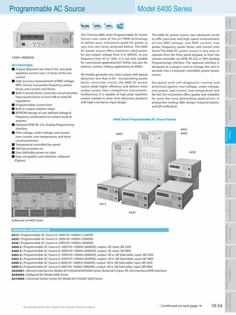
10-54All specifications are subject to change without notice. All specifications are subject to change without notice.
Flat PanelD
isplayPow
er Electronics
Electrical Safety
General
PurposePassive
Component
Semiconductor/
ICBattery Test & Autom
ationAutom
atedO
ptical Inspection Photovoltaic Test
& Automation
PXI Test &
Measurem
ent Video & Color
LED/
LightingO
ptical D
evicesIntelligent
Manufacturing System
Turnkey Test & Autom
ation
6415 : Programmable AC Source 0~300V/45-1000Hz (1500VA)6420 : Programmable AC Source 0~300V/45-1000Hz (2000VA)6430 : Programmable AC Source 0~300V/45-1000Hz (3000VA)6460-2 : Programmable AC Source 0~300V/45-1000Hz (6000VA), output 1Ø, input 3Ø 220V6460-3 : Programmable AC Source 0~300V/45-1000Hz (6000VA), output 1Ø, input 3Ø 380V6463-2 : Programmable AC Source 0~300V/45-1000Hz (6000VA), output 1Ø or 3Ø Selectable, input 3Ø 220V6463-3 : Programmable AC Source 0~300V/45-1000Hz (6000VA), output 1Ø or 3Ø Selectable, input 3Ø 380V6490-2 : Programmable AC Source 0-300V/45-1000Hz (9000VA), output 1Ø or 3Ø Selectable, input 3Ø 220V6490-3 : Programmable AC Source 0-300V/45-1000Hz (9000VA), output 1Ø or 3Ø Selectable, input 3Ø 380VA650001 : Remote Interface for Model 6415/6420/6430/6500 Series (External V Input, RS-232 Interface,GPIB Interface)A640004 : Softpanel for Model 6400 SeriesA610004 : Universal Socket Center for Model 6415/6420/ 6430 Series
6400 Series Programmable AC Source Family
1500~9000VA
KEY FEATURES Output distortion less than 0.3%, and peak repetitive current over 2.5 times of the rms current High accuracy measurement of RMS voltage, RMS current, true power, frequency, power factor, and current crest factor Built-in power factor correction circuit provides input power factor of over 0.98 to meet IEC regulations Programmable current limit Built-in output isolation relays EEPROM storage of user defined voltage & frequency combination for instant recall at anytime Optional GPIB, RS-232, Analog Programming interface Over-voltage, under-voltage, over-power, over-current, over-temperature, and short circuit protection Temperature controlled fan speed Self-test at power-on User-definable power-on state Easy use graphic user interface: softpanel
(Option)
The Chroma 6400 series Programmable AC Power Source uses state of the art PWM technology to deliver pure, instrument grade AC power at very low cost never achieved before. The 6400 AC power source offers maximum rated power for any output voltage from 0 to 300VAC, at any frequency from 45 to 1kHz. It is not only suitable for commercial applications(47-63Hz), but also for avionics, marine, military applications at 400Hz.
All models generate very clean output with typical distortion less than 0.3%. Incorporating power factor correction circuit, the 6400 AC power source yields higher efficiency and delivers more output power than competitive instruments. Furthermore, it is capable of high peak repetitive current needed to drive most electronic products with high crest factor input design.
Softpanel of 6400 Series
ORDERING INFORMATION
The 6400 AC power source uses advanced circuit to offer precision and high speed measurement of true RMS voltage, true RMS current, true power, frequency, power factor, and current crest factor.The 6400 AC power source is very easy to operate from the front panel keypad, or from the remote controller via GPIB, RS-232 or APG (Analog Programming) interface. The optional interface is designed as a plug-in card to change the unit in seconds into a computer controlled system power source.
Designed with self diagnostic routine and protected against over-voltage, under-voltage, over-power, over-current, over-temperature and fan fail, the instrument offers quality and reliability for even the most demanding applications in production testing, R&D design characterization, and QA verification.
Programmable AC Source Model 6400 Series
• Continued on next page
6430
6420
6415
646064636490
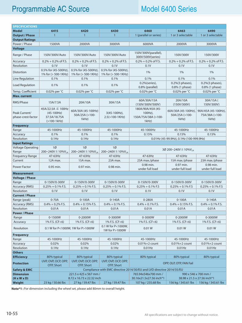
10-55 All specifications are subject to change without notice. All specifications are subject to change without notice.
Programmable AC Source Model 6400 Series
SPECIFICATIONSModel 6415 6420 6430 6460 6463 6490 Output / Phase 1 1 1 1 (parallel or series) 1 or 3 selectable 1 or 3 selectable Output RatingsPower / Phase 1500VA 2000VA 3000VA 6000VA 2000VA 3000VA Voltage
Range / Phase 150V/300V/Auto 150V/300V/Auto 150V/300V/Auto150V/300V(parallel),
300V/500V(series)150V/300V 150V/300V
Accuracy 0.2% + 0.2% of F.S. 0.2% + 0.2% of F.S. 0.2% + 0.2% of F.S. 0.2% + 0.2% of F.S. 0.2% + 0.2% of F.S. 0.2% + 0.2% of F.S.Resolution 0.1V 0.1V 0.1V 0.1V 0.1V 0.1V
Distortion0.5% for (45-500Hz), 1% for (> 500-1KHz)
0.5% for (45-500Hz), 1% for (> 500-1KHz)
0.5% for (45-500Hz), 1% for (> 500-1KHz)
1% 1% 1%
Line Regulation 0.1% 0.1% 0.1% 0.1% 0.1% 0.1%
Load Regulation 0.1% 0.1% 0.1%0.2%(series),
0.8% (parallel)0.2%(3 phases), 0.8% (1 phase)
0.2%(3 phases), 0.8% (1 phase)
Temp. Coefficient 0.02% per ˚C 0.02% per ˚C 0.02% per ˚C 0.02% per ˚C 0.02% per ˚C 0.02% per ˚CMax. current
RMS/Phase 15A/7.5A 20A/10A 30A/15A 60A/30A/15A
(150V/300V/500V)20A/10A
(150V/300V)30A/15A (
150V/300V)
Peak Current/phase-crest-factor
45A/22.5A ≦ 100Hz(45-100Hz)
37.5A/18.75A (>100-1kHz)
60A/30A (45-100Hz)50A/25A (>100-
1kHz)
3(45-100Hz), 2.5(>100-1KHz)
180A/90A/45A (45-100Hz),
150A/75A/38A (>100-1kHz)
60A/30A (45-100Hz),50A/25A (>100-
1kHz)
90A/45A (45-100Hz), 75A/38A (>100-
1kHz)
FrequencyRange 45-1000Hz 45-1000Hz 45-1000Hz 45-1000Hz 45-1000Hz 45-1000HzAccuracy 0.1% 0.1% 0.1% 0.15% 0.15% 0.15% Resolution 0.1Hz 0.1Hz 0.1Hz 0.01Hz (45-99.9Hz), 0.1Hz (100-999.9Hz)Input RatingsVoltage OperatingRange
1Ø 200~240V±10%VLN
1Ø 200~240V±10%VLN
1Ø 200~240V±10%VLN
3Ø 200~240V±10%VLN
Frequency Range 47-63Hz 47-63Hz 47-63Hz 47-63Hz 47-63Hz 47-63HzCurrent 12A max. 15A max. 23A max. 23A max./phase 15A max./phase 23A max./phase
Power Factor 0.95 min. 0.97 min. 0.98 min.0.98 min.
under full load0.97 min.
under full load0.98 min.
under full loadMeasurementVoltage / PhaseRange 0-150V/0-300V 0-150V/0-300V 0-150V/0-300V 0-150V/0-300V 0-150V/0-300V 0-150V/0-300V Accuracy (RMS) 0.25% + 0.1% F.S. 0.25% + 0.1% F.S. 0.25% + 0.1% F.S. 0.25% + 0.1% F.S 0.25% + 0.1% F.S 0.25% + 0.1% F.SResolution 0.1V 0.1V 0.1V 0.1V 0.1V 0.1VCurrent / PhaseRange (peak) 0-70A 0-100A 0-140A 0-280A 0-100A 0-140AAccuracy (RMS) 0.4% + 0.2% F.S. 0.4% + 0.15% F.S. 0.4% + 0.1% F.S. 0.4% + 0.1% F.S. 0.4% + 0.15% F.S. 0.4% + 0.1% F.S.Resolution 0.01A 0.01A 0.01A 0.01A 0.01A 0.01A Power / Phase Range 0-1500W 0-2000W 0-3000W 0-3000W 0-2000W 0-3000W Accuracy 1% F.S. (CF<6) 1% F.S. (CF<6) 1% F.S. (CF<6) 1% F.S. (CF<6) 1% F.S. (CF<6) 1% F.S. (CF<6)
Resolution 0.1 W for P<1000W, 1W for P>1000W0.1 W for P<1000W,
1W for P>1000W0.01 W 0.01 W 0.01 W
FrequencyRange 45-1000Hz 45-1000Hz 45-1000Hz 45-1000Hz 45-1000Hz 45-1000HzAccuracy 0.02% 0.02% 0.02% 0.01%+2 count 0.01%+2 count 0.01%+2 countResolution 0.1Hz 0.1Hz 0.1Hz 0.01Hz 0.01Hz 0.01HzOthersEfficiency 80% typical 80% typical 80% typical 80% typical 80% typical 80% typical
ProtectionUVP, OVP, OCP, OPP,
OTP, ShortUVP, OVP, OCP, OPP,
OTP, ShortUVP, OVP, OCP, OPP,
OTP, ShortOPP, OLP, OTP, FAN Fail
Safety & EMC Compliance with EMC directive 2014/30/EU and LVD directive 2014/35/EUDimension(H x W x D)
221.5 x 425 x 567 mm / 8.72 x 16.73 x 22.32 inch
765.94x546x700 mm /30.16x21.5x27.56 inch*1
990 x 546 x 700 mm /38.98 x 21.5 x 27.56 inch*1
Weight 23 kg / 50.66 lbs 27 kg / 59.47 lbs 27 kg / 59.47 lbs 107 kg / 235.68 lbs 156 kg / 343.61 lbs 156 kg / 343.61 lbs
Note*1 : For dimension including the wheel set, please add 80mm to overall height.
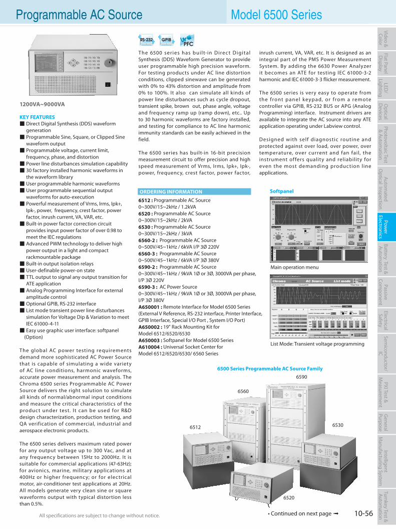
10-56All specifications are subject to change without notice. All specifications are subject to change without notice.
Flat PanelD
isplayPow
er Electronics
Electrical Safety
General
PurposePassive
Component
Semiconductor/
ICBattery Test & Autom
ationAutom
atedO
ptical Inspection Photovoltaic Test
& Automation
PXI Test &
Measurem
ent Video & Color
LED/
LightingO
ptical D
evicesIntelligent
Manufacturing System
Turnkey Test & Autom
ation Programmable AC Source Model 6500 Series
6512 : Programmable AC Source0~300V/15~2kHz / 1.2kVA6520 : Programmable AC Source0~300V/15~2kHz / 2kVA6530 : Programmable AC Source0~300V/15~2kHz / 3kVA6560-2 : Programmable AC Source0~500V/45~1kHz / 6kVA I/P 3Ø 220V6560-3 : Programmable AC Source0~500V/45~1kHz / 6kVA I/P 3Ø 380V6590-2 : Programmable AC Source0~300V/45~1kHz / 9kVA 1Ø or 3Ø, 3000VA per phase, I/P 3Ø 220V6590-3 : AC Power Source0~300V/45~1kHz / 9kVA 1Ø or 3Ø, 3000VA per phase, I/P 3Ø 380VA650001 : Remote Interface for Model 6500 Series (External V Reference, RS-232 interface, Printer Interface, GPIB Interface, Special I/O Port , System I/O Port)A650002 : 19" Rack Mounting Kit forModel 6512/6520/6530A650003 : Softpanel for Model 6500 SeriesA610004 : Universal Socket Center forModel 6512/6520/6530/ 6560 Series
The 6500 ser ies has bui l t-in Direc t Digital Synthesis (DDS) Waveform Generator to provide user programmable high precision waveform. For testing products under AC line distortion conditions, clipped sinewave can be generated with 0% to 43% distortion and amplitude from 0% to 100%. It also can simulate all kinds of power line disturbances such as cycle dropout, transient spike, brown out, phase angle, voltage and frequency ramp up (ramp down), etc.. Up to 30 harmonic waveforms are factory installed, and testing for compliance to AC line harmonic immunity standards can be easily achieved in the field.
The 6500 series has built-in 16-bit precision measurement circuit to offer precision and high speed measurement of Vrms, Irms, Ipk+, Ipk-, power, frequency, crest factor, power factor,
1200VA~9000VA
KEY FEATURES Direct Digital Synthesis (DDS) waveform generation Programmable Sine, Square, or Clipped Sine waveform output Programmable voltage, current limit, frequency, phase, and distortion Power line disturbances simulation capability 30 factory installed harmonic waveforms in the waveform library User programmable harmonic waveforms User programmable sequential output waveforms for auto-execution Powerful measurement of Vrms, Irms, Ipk+, Ipk-, power, frequency, crest factor, power factor, inrush current, VA, VAR, etc. Built-in power factor correction circuit provides input power factor of over 0.98 to meet the IEC regulations Advanced PWM technology to deliver high power output in a light and compact rackmountable package Built-in output isolation relays User-definable power-on state TTL output to signal any output transition for ATE application Analog Programming Interface for external amplitude control Optional GPIB, RS-232 interface List mode transient power line disturbances simulation for Voltage Dip & Variation to meet IEC 61000-4-11 Easy use graphic user interface: softpanel
(Option)
The global AC power testing requirements demand more sophisticated AC Power Source that is capable of simulating a wide variety of AC line conditions, harmonic waveforms, accurate power measurement and analysis. The Chroma 6500 series Programmable AC Power Source delivers the right solution to simulate all kinds of normal/abnormal input conditions and measure the critical characteristics of the product under test. It can be used for R&D design characterization, production testing, and QA verif ication of commercial, industrial and aerospace electronic products.
The 6500 series delivers maximum rated power for any output voltage up to 300 Vac, and at any frequency between 15Hz to 2000Hz. It is suitable for commercial applications (47-63Hz); for avionics, marine, military applications at 400Hz or higher frequency; or for e lectrical motor, air-conditioner test applications at 20Hz. All models generate very clean sine or square waveforms output with typical distortion less than 0.5%.
inrush current, VA, VAR, etc. It is designed as an integral part of the PMS Power Measurement System. By adding the 6630 Power Analyzer it becomes an ATE for testing IEC 61000-3-2 harmonic and IEC 61000-3-3 flicker measurement.
The 6500 series is very easy to operate from the f ront panel key pad, or f rom a remote controller via GPIB, RS-232 BUS or APG (Analog Programming) interface. Instrument drivers are available to integrate the AC source into any ATE application operating under Labview control.
Designed with self diagnostic routine and protected against over load, over power, over temperature, over current and fan fail, the instrument of fers quality and reliability for even the most demanding production l ine applications.
6500 Series Programmable AC Source Family
6520
65306512
6560
6590
Main operation menu
List Mode: Transient voltage programming
ORDERING INFORMATION Softpanel
• Continued on next page
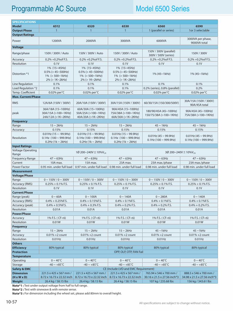
10-57 All specifications are subject to change without notice. All specifications are subject to change without notice.
Programmable AC Source Model 6500 Series
SPECIFICATIONSModel 6512 6520 6530 6560 6590Output Phase 1 1 1 1 (parallel or series) 1or 3 selectableOutput Ratings
Power 1200VA 2000VA 3000VA 6000VA3000VA per phase,
9000VA totalVoltage
Range/phase 150V / 300V / Auto 150V / 300V / Auto 150V / 300V / Auto150V / 300V (parallel)300V / 500V (series)
150V / 300V
Accuracy 0.2% +0.2%of F.S. 0.2% +0.2%of F.S. 0.2% +0.2%of F.S. 0.2% +0.2%of F.S. 0.2% +0.2%of F.S.Resolution 0.1V 0.1V 0.1V 0.1V 0.1V
Distortion *1
1% (15~45Hz)0.5% (> 45~500Hz)1% (> 500~1kHz)2% (> 1K~2kHz)
1% (15~45Hz)0.5% (> 45~500Hz)1% (> 500~1kHz)2% (> 1K~2kHz)
1% (15~45Hz)0.5% (> 45~500Hz)1% (> 500~1kHz)2% (> 1K~2kHz)
1% (45~1kHz) 1% (45~1kHz)
Line Regulation 0.1% 0.1% 0.1% 0.1% 0.1%Load Regulation *2 0.1% 0.1% 0.1% 0.2% (series), 0.8% (parallel) 0.2%Temp. Coefficient 0.02% per˚C 0.02% per˚C 0.02% per˚C 0.02% per˚C 0.02% per˚CMax. Current/Phase
RMS 12A/6A (150V / 300V) 20A/10A (150V / 300V) 30A/15A (150V / 300V) 60/30/15A (150/300/500V)30A/15A (150V / 300V)
90A/45A total
peak36A/18A (15~100Hz)
30A/15A (>100~1KHz)24A/12A (>1K~2KHz)
60A/30A (15~100Hz)50A/25A (>100~1KHz)40A/20A (>1K~2KHz)
90A/45A (15~100Hz)75A/38A (>100~1KHz)60A/30A (>1K~2KHz)
180/90/45A (45~100Hz)150/75/38A (>100~1KHz)
90A/45A (45~100Hz)75A/38A (>100~1KHz)
FrequencyRange 15 ~ 2kHz 15 ~ 2kHz 15 ~ 2kHz 45 ~ 1kHz 45 ~ 1kHzAccuracy 0.15% 0.15% 0.15% 0.15% 0.15%
Resolution0.01Hz (15 ~ -99.9Hz)0.1Hz (100 ~ 999.9Hz)
0.2Hz (1k ~ 2kHz)
0.01Hz (15 ~ 99.9Hz)0.1Hz (100 ~ 999.9Hz)
0.2Hz (1k ~ 2kHz)
0.01Hz (15 ~ 99.9Hz)0.1Hz (100 ~ 999.9Hz)
0.2Hz (1k ~ 2kHz)
0.01Hz (45 ~ 99.9Hz)0.1Hz (100 ~ 999.9Hz)
0.01Hz (45 ~ 99.9Hz)0.1Hz (100 ~ 999.9Hz)
Input RatingsVoltage Operating Range
1Ø 200~240V±10%VLN 3Ø 200~240V±10%VLN
Frequency Range 47 ~ 63Hz 47 ~ 63Hz 47 ~ 63Hz 47 ~ 63Hz 47 ~ 63HzCurrent 10A max. 15A max. 23A max. 23A max./phase 23A max./phasePower Factor 0.95 min. under full load 0.97 min. under full load 0.98 min. under full load 0.98 min. under full load 0.98 min. under full loadMeasurementVoltage/PhaseRange 0 ~ 150V / 0 ~ 300V 0 ~ 150V / 0 ~ 300V 0 ~ 150V / 0 ~ 300V 0 ~ 150V / 0 ~ 300V 0 ~ 150V / 0 ~ 300VAccuracy (RMS) 0.25% + 0.1% F.S. 0.25% + 0.1% F.S. 0.25% + 0.1% F.S. 0.25% + 0.1% F.S. 0.25% + 0.1% F.S.Resolution 0.1V 0.1V 0.1V 0.1V 0.1VCurrent/PhaseRange (peak) 0 ~ 60A 0 ~ 100A 0 ~ 140A 0 ~ 280A 0 ~ 140AAccuracy (RMS) 0.4% + 0.25%F.S. 0.4% + 0.15%F.S. 0.4% + 0.1%F.S. 0.4% + 0.1%F.S. 0.4% + 0.1%F.S.Accuracy (peak) 0.4% + 0.5%F.S. 0.4% + 0.3% F.S. 0.4% + 0.2% F.S. 0.4% + 0.2% F.S. 0.4% + 0.2% F.S.Resolution 0.01A 0.01A 0.01A 0.01A 0.01APower/PhaseAccuracy 1% F.S. ( CF<6) 1% F.S. ( CF<6) 1% F.S. ( CF<6) 1% F.S. ( CF<6) 1% F.S. ( CF<6)Resolution 0.01W 0.01W 0.01W 0.01W 0.01WFrequencyRange 15 ~ 2kHz 15 ~ 2kHz 15 ~ 2kHz 45 ~1kHz 45 ~1kHzAccuracy 0.01% +2 count 0.01% +2 count 0.01% +2 count 0.01% +2 count 0.01% +2 countResolution 0.01Hz 0.01Hz 0.01Hz 0.01Hz 0.01HzOthersEfficiency 80% typical 80% typical 80% typical 80% typical 80% typicalProtection OPP, OLP, OTP, FAN FailTemperatureOperating 0 ~ 40˚C 0 ~ 40˚C 0 ~ 40˚C 0 ~ 40˚C 0 ~ 40˚CStorage -40 ~ +85˚C -40 ~ +85˚C -40 ~ +85˚C -40 ~ +85˚C -40 ~ +85˚CSafety & EMC CE (Include LVD and EMC Requirement)Dimension(H x W x D)
221.5 x 425 x 567 mm /8.72 x 16.73 x 22.32 inch
221.5 x 425 x 567 mm /8.72 x 16.73 x 22.32 inch
221.5 x 425 x 567 mm /8.72 x 16.73 x 22.32 inch
765.94 x 546 x 700 mm /30.16 x 21.5 x 27.56 inch*3
888.5 x 546 x 700 mm /34.98 x 21.5 x 27.56 inch*3
Weight 26.4 kg / 58.15 lbs 26.4 kg / 58.15 lbs 26.4 kg / 58.15 lbs 107 kg / 235.68 lbs 156 kg / 343.61 lbsNote*1 : Test under output voltage from half to full range. Note*2 : Test with sinewave & with remote sense.Note*3 : For dimension including the wheel set, please add 80mm to overall height.
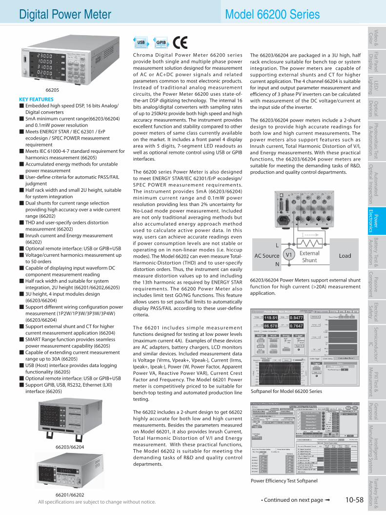
10-58All specifications are subject to change without notice. All specifications are subject to change without notice.
Flat PanelD
isplayPow
er Electronics
Electrical Safety
General
PurposePassive
Component
Semiconductor/
ICBattery Test & Autom
ationAutom
atedO
ptical Inspection Photovoltaic Test
& Automation
PXI Test &
Measurem
ent Video & Color
LED/
LightingO
ptical D
evicesIntelligent
Manufacturing System
Turnkey Test & Autom
ation Digital Power Meter Model 66200 Series
KEY FEATURES Embedded high speed DSP, 16 bits Analog/ Digital converters 5mA minimum current range(66203/66204) and 0.1mW power resolution Meets ENERGY STAR / IEC 62301 / ErP ecodesign / SPEC POWER measurement requirement Meets IEC 61000-4-7 standard requirement for harmonics measurement (66205) Accumulated energy methods for unstable power measurement User-define criteria for automatic PASS/FAIL judgment Half rack width and small 2U height, suitable for system integration Dual shunts for current range selection providing high accuracy over a wide current range (66202) THD and user-specify orders distortion measurement (66202) Inrush current and Energy measurement (66202) Optional remote interface: USB or GPIB+USB Voltage/current harmonics measurement up to 50 orders Capable of displaying input waveform DC component measurement reading Half rack width and suitable for system integration, 2U height (66201/66202,66205) 3U height, 4 input modules design (66203/66204) Support different wiring configuration power measurement (1P2W/1P3W/3P3W/3P4W) (66203/66204) Support external shunt and CT for higher current measurement application (66204) SMART Range function provides seamless power measurement capability (66205) Capable of extending current measurement range up to 30A (66205) USB (Host) interface provides data logging functionality (66205) Optional remote interface: USB or GPIB+USB Support GPIB, USB, RS232, Ethernet (LXI) interface (66205)
Chroma Digita l Power M eter 66200 ser ies provide both single and multiple phase power measurement solution designed for measurement of AC or AC+DC power signals and related parameters common to most electronic products. Instead of traditional analog measurement circuits, the Power Meter 66200 uses state-of-the-art DSP digitizing technology. The internal 16 bits analog/digital converters with sampling rates of up to 250kHz provide both high speed and high accuracy measurements. The instrument provides excellent function and stability compared to other power meters of same class currently available on the market. It includes a front panel 4 display area with 5 digits, 7-segment LED readouts as well as optional remote control using USB or GPIB interfaces.
The 66200 series Power Meter is also designed to meet ENERGY STAR/IEC 62301/ErP ecodesign/SPEC POWER measurement requirements. The instrument provides 5mA (66203/66204) minimum current range and 0.1mW power resolution providing less than 2% uncertainty for No-Load mode power measurement. Included are not only traditional averaging methods but also accumulated energy approach method used to calculate active power data. In this way, users can achieve accurate readings even if power consumption levels are not stable or operating on in non-linear modes (i.e. hiccup modes). The Model 66202 can even measure Total-Harmonic-Distortion (THD) and to user-specify distortion orders. Thus, the instrument can easily measure distortion values up to and including the 13th harmonic as required by ENERGY STAR requirements. The 66200 Power Meter also includes limit test GO/NG functions. This feature allows users to set pass/fail limits to automatically display PASS/FAIL according to these user-define criteria.
Th e 66201 i n c l u d e s s i m p l e m e a s u re m e nt functions designed for testing at low power levels (maximum current 4A). Examples of these devices are AC adapters, battery chargers, LCD monitors and similar devices. Included measurement data is Voltage (Vrms, Vpeak+, Vpeak-), Current (Irms, Ipeak+, Ipeak-), Power (W, Power Factor, Apparent Power VA, Reactive Power VAR), Current Crest Factor and Frequency. The Model 66201 Power meter is competitively priced to be suitable for bench-top testing and automated production line testing.
The 66202 includes a 2-shunt design to get 66202 highly accurate for both low and high current measurements. Besides the parameters measured on Model 66201, it also provides Inrush Current, Total Harmonic Distortion of V/I and Energy measurement. With these practical functions, The Model 66202 is suitable for meeting the demanding tasks of R&D and quality control departments.
Softpanel for Model 66200 Series
66205
66203/66204
66201/66202
Power Efficiency Test Softpanel
The 66203/66204 are packaged in a 3U high, half rack enclosure suitable for bench top or system integration. The power meters are capable of supporting external shunts and CT for higher current application. The 4 channel 66204 is suitable for input and output parameter measurement and efficiency of 3 phase PV inverters can be calculated with measurement of the DC voltage/current at the input side of the inverter.
The 66203/66204 power meters include a 2-shunt design to provide high accurate readings for both low and high current measurements. The power meters also support features such as Inrush current, Total Harmonic Distortion of V/I, and Energy measurements. With these practical functions, the 66203/66204 power meters are suitable for meeting the demanding tasks of R&D, production and quality control departments.
66203/66204 Power Meters support external shunt function for high current (>20A) measurement application.
• Continued on next page
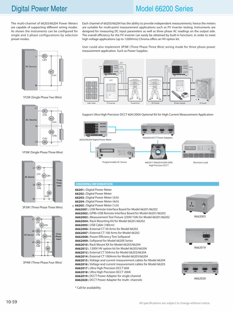
10-59 All specifications are subject to change without notice. All specifications are subject to change without notice.
66201 : Digital Power Meter 66202 : Digital Power Meter 66203 : Digital Power Meter (3ch)66204 : Digital Power Meter (4ch)66205 : Digital Power Meter (1ch)A662001 : USB Remote Interface Board for Model 66201/66202A662002 : GPIB+USB Remote Interface Board for Model 66201/66202A662003 : Measurement Test Fixture (250V/10A) for Model 66201/66202A662004 : Rack Mounting Kit for Model 66201/66202A662005 : USB Cable (180cm)A662006 : External CT 50 Arms for Model 66202A662007 : External CT 100 Arms for Model 66202A662008 : Power Efficiency Test SoftpanelA662009 : Softpanel for Model 66200 SeriesA662010 : Rack Mount Kit for Model 66203/66204A662012 : 1200V HV option kit for Model 66203/66204A662013 : External CT 50Arms for Model 66203/66204A662014 : External CT 100Arms for Model 66203/66204A662015 : Voltage and current measurement cables for Model 66204A662016 : Voltage and current measurement cables for Model 66203A662017 : Ultra High Precision DCCT 60AA662018 : Ultra High Precision DCCT 200AA662019 : DCCT Power Adapter for single channelA662020 : DCCT Power Adapter for multi- channels
* Call for availability
*
A662003
ORDERING INFORMATION
The multi-channel of 66203/66204 Power Meters are capable of supporting different wiring modes. As shown the instruments can be configured for single and 3 phase configurations by selection preset modes.
Each channel of 66203/66204 has the ability to provide independent measurements; hence the meters are suitable for multi-point measurement applications such as PV inverter testing. Instruments are designed for measuring DC input parameters as well as three phase AC readings on the output side. The overall efficiency for the PV inverter can easily be obtained by built-in functions. In order to meet high voltage applications (up to 1200Vrms) Chroma offers an HV option kit.
User could also implement 3P3W (Three Phase Three Wire) wiring mode for three phase power measurement application. Such as Power Supplies.
Support Ultra High Precision DCCT 60A/200A Optional Kit for High Current Measurement Application
Digital Power Meter Model 66200 Series
1P2W (Single Phase Two Wire)
3P3W (Three Phase Three Wire)
3P4W (Three Phase Four Wire)
1P3W (Single Phase Three Wire)
66203/66204 Digital Power MeterA662020 DCCT Power Adapters
Programmable AC Source A662017/A662018 60A/200A High Precision DCCT
Electronic Load
A662019
A662020
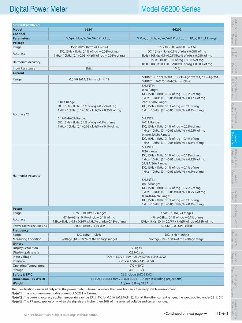
10-60All specifications are subject to change without notice. All specifications are subject to change without notice.
Flat PanelD
isplayPow
er Electronics
Electrical Safety
General
PurposePassive
Component
Semiconductor/
ICBattery Test & Autom
ationAutom
atedO
ptical Inspection Photovoltaic Test
& Automation
PXI Test &
Measurem
ent Video & Color
LED/
LightingO
ptical D
evicesIntelligent
Manufacturing System
Turnkey Test & Autom
ation Digital Power Meter Model 66200 Series
SPECIFICATIONS-1Model 66201 66202Channel 1 1Parameters V, Vpk, I, Ipk, W, VA, VAR, PF, CF_I, F V, Vpk, I, Ipk, Is, W, VA, VAR, PF, CF_I, F, THD_V, THD_I, EnergyVoltageRange 150/300/500Vrms (CF = 1.6) 150/300/500Vrms (CF = 1.6)
AccuracyDC, 15Hz - 1kHz: 0.1% of rdg + 0.08% of rng
1kHz - 10kHz: (0.1+0.05*KHz)% of rdg + 0.08% of rngDC, 15Hz - 1kHz: 0.1% of rdg + 0.08% of rng
1kHz - 10kHz: (0.1+0.05*KHz)% of rdg + 0.08% of rng
Harmonics Accuracy --15Hz - 1kHz: 0.1% of rdg + 0.08% of rng
1kHz - 10kHz: (0.1+0.05*KHz)% of rdg + 0.08% of rngInput Resistance 1MΩ 1MΩCurrent
Range 0.01/0.1/0.4/2 Arms (CF=4) *1SHUNT H : 0.2/2/8/20Arms ([email protected]/2/8A, CF = 4@ 20A)SHUNT L : 0.01/0.1/0.4/2Arms (CF=4)
Accuracy *2
0.01A Range:DC, 15Hz - 1kHz: 0.1% of rdg + 0.25% of rng1kHz - 10kHz: (0.1+0.05 x kHz)% + 0.25% of rng
0.1A/0.4A/2A Range:DC, 15Hz - 1kHz: 0.1% of rdg + 0.1% of rng1kHz - 10kHz: (0.1+0.05 x kHz)% + 0.1% of rng
SHUNT H:0.2A Range:DC, 15Hz - 1kHz: 0.1% of rdg + 0.12% of rng1kHz - 10kHz: (0.1+0.05 x kHz)% + 0.12% of rng2A/8A/20A Range:DC, 15Hz - 1kHz: 0.1% of rdg + 0.1% of rng1kHz - 10kHz: (0.1+0.05 x kHz)% + 0.1% of rng
SHUNT L:0.01A Range:DC, 15Hz - 1kHz: 0.1% of rdg + 0.25% of rng1kHz - 10kHz: (0.1+0.05 x kHz)% + 0.25% of rng0.1A/0.4A/2A Range:DC, 15Hz - 1kHz: 0.1% of rdg + 0.1% of rng1kHz - 10kHz: (0.1+0.05 x kHz)% + 0.1% of rng
Harmonics Accuracy --
SHUNT H:0.2A Range:DC, 15Hz - 1kHz: 0.1% of rdg + 0.12% of rng1kHz - 10kHz: (0.1+0.05 x kHz)% + 0.12% of rng2A/8A/20A Range:DC, 15Hz - 1kHz: 0.1% of rdg + 0.1% of rng1kHz - 10kHz: (0.1+0.05 x kHz)% + 0.1% of rng
SHUNT L:0.01A Range:DC, 15Hz - 1kHz: 0.1% of rdg + 0.25% of rng1kHz - 10kHz: (0.1+0.05 x kHz)% + 0.25% of rng0.1A/0.4A/2A Range:DC, 15Hz - 1kHz: 0.1% of rdg + 0.1% of rng1kHz - 10kHz: (0.1+0.05 x kHz)% + 0.1% of rng
PowerRange 1.5W ~ 1000W, 12 ranges 1.5W ~ 10kW, 24 ranges
Accuracy47Hz~63Hz : 0.1% of rdg + 0.1% of rng
15Hz~1kHz : (0.1+ 0.2/PF x kHz)% of rdg+0.18% of rng47Hz~63Hz : 0.1% of rdg + 0.1% of rng
15Hz~1kHz : (0.1+ 0.2/PF x kHz)% of rdg+0.18% of rngPower Factor accuracy *3 0.006+(0.003/PF) x kHz 0.006+(0.003/PF) x kHzFrequencyRange DC, 15Hz ~ 10kHz DC, 15Hz ~ 10kHzMeasuring Condition Voltage (10 ~ 100% of the voltage range) Voltage (10 ~ 100% of the voltage range)OthersDisplay Resolution 5 DigitsDisplay update rate 0.25~2 secInput Voltage 90V ~ 130V /180V ~ 250V, 50Hz/ 60Hz, 30VAInterface Option: USB or GPIB+USBOperating Temperature 0˚C ~ 40˚CStorage -40˚C ~ 85˚CSafety & EMC CE (include EMC & LVD)Dimension (H x W x D) 88 x 212 x 348.1 mm / 3.46 x 8.35 x 13.7 inch (excluding projections)Weight Approx. 3.8 kg / 8.37 lbs
The specifications are valid only after the power meter is turned on more than one hour in a thermally stable environment.Note*1 : The maximum measurable current of 66201 is 4 Arms.Note*2 : The current accuracy applies temperature range 23 ± 1˚C for 0.01A & 0.2A(CF=2). For all the other current ranges, the spec. applied under 23 ± 5˚C.Note*3 : The PF spec. applies only when the signals are higher then 50% of the selected voltage and current ranges.
• Continued on next page
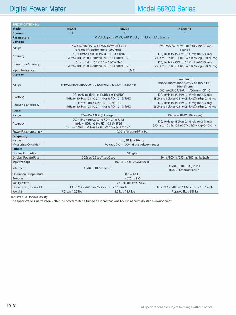
10-61 All specifications are subject to change without notice. All specifications are subject to change without notice.
Digital Power Meter Model 66200 Series
Note*1 : Call for availabilityThe specifications are valid only after the power meter is turned on more than one hour in a thermally stable environment.
SPECIFICATIONS-2Model 66203 66204 66205 *1Channel 3 4 1Parameters V, Vpk, I, Ipk, Is, W, VA, VAR, PF, CFi, F, THD V, THD I, EnergyVoltage
Range 15V/30V/60V/150V/300V/600Vrms (CF=2 ), 6 range HV option up to 1200Vrms
15V/30V/60V/150V/300V/600Vrms (CF=2 ), 6 range
AccuracyDC, 10Hz to 1kHz : 0.1% RD + 0.08% RNG
1kHz to 10kHz: (0.1+0.05*kHz)% RD + 0.08% RNGDC, 10Hz to 850Hz : 0.1% rdg+0.05% rng
850Hz to 10kHz: (0.1+0.05xkHz)% rdg+0.08% rng
Harmonics Accuracy 10Hz to 1kHz : 0.1% RD + 0.08% RNG1kHz to 10kHz: (0.1+0.05*kHz)% RD + 0.08% RNG
DC, 10Hz to 850Hz : 0.1% rdg+0.05% rng850Hz to 10kHz: (0.1+0.05xkHz)% rdg+0.08% rng
Input Resistance 2MΩCurrent
Range 5mA/20mA/50mA/200mA/500mA/2A/5A/20Arms (CF=4)
Low Shunt: 5mA/20mA/50mA/200mA/300mA (CF=4)
High Shunt: 500mA/2A/5A/20Arms/30Arms (CF=4)
Accuracy DC, 10Hz to 1kHz : 0.1% RD + 0.1% RNG1kHz to 10kHz : (0.1+0.05 x kHz)% RD + 0.1% RNG
DC, 10Hz to 850Hz : 0.1% rdg+0.05% rng850Hz to 10kHz: (0.1+0.05xkHz)% rdg+0.1% rng
Harmonics Accuracy 10Hz to 1kHz : 0.1% RD + 0.1% RNG1kHz to 10kHz : (0.1+0.05 x kHz)% RD + 0.1% RNG
DC, 10Hz to 850Hz : 0.1% rdg+0.05% rng850Hz to 10kHz: (0.1+0.05xkHz)% rdg+0.1% rng
PowerRange 75mW ~ 12kW (48 ranges) 75mW ~ 18kW (60 ranges)
AccuracyDC, 47Hz ~ 63Hz : 0.1% RD + 0.1% RNG
10Hz ~ 1KHz : 0.1% RD + 0.18% RNG1KHz ~ 10KHz : (0.1+0.1 x kHz)% RD + 0.18% RNG
DC, 10Hz to 850Hz : 0.1% rdg+0.05% rng850Hz to 10kHz: (0.1+0.07xkHz)% rdg+0.15% rng
Power Factor accuracy 0.001+(15ppm/PF) x Hz FrequencyRange DC, 10Hz ~ 10kHzMeasuring Condition Voltage (10 ~ 100% of the voltage range)OthersDisplay Resolution 5 DigitsDisplay Update Rate 0.25sec/0.5sec/1sec/2sec 50ms/100ms/250ms/500ms/1s/2s/5sInput Voltage 100~240V±10%, 50/60Hz
Interface USB+GPIB (Standard) USB+GPIB+USB (Host)+RS232+Ethernet (LXI) *1
Operation Temperature 0˚C ~ 40˚CStorage -40˚C ~ 85˚CSafety & EMC CE (include EMC & LVD)Dimension (H x W x D) 133 x 212 x 420 mm / 5.25 x 8.25 x 16.3 inch 88 x 212 x 348mm / 3.46 x 8.35 x 13.7 inch Weight 7.5 kg / 16.5 lbs 8.5 kg / 18.7 lbs Approx. 4kg / 8.8 lbs
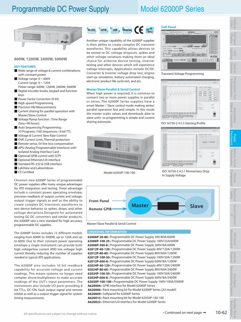
10-62All specifications are subject to change without notice. All specifications are subject to change without notice.
Flat PanelD
isplayPow
er Electronics
Electrical Safety
General
PurposePassive
Component
Semiconductor/
ICBattery Test & Autom
ationAutom
atedO
ptical Inspection Photovoltaic Test
& Automation
PXI Test &
Measurem
ent Video & Color
LED/
LightingO
ptical D
evicesIntelligent
Manufacturing System
Turnkey Test & Autom
ation Programmable DC Power Supply Model 62000P Series
600W, 1200W, 2400W, 5000W
KEY FEATURES Wide range of voltage & current combinations with constant power Voltage range: 0 ~ 600V Current range: 0 ~ 120A Power range: 600W, 1200W, 2400W, 5000W Digital encoder knobs, keypad and function keys Power Factor Correction (0.95) High-speed Programming Precision V&I Measurements Current sharing for parallel operation with Master/Slave Control Voltage Ramp function : Time Range (5ms~99 hours) Auto Sequencing Programming : 10 Programs /100 Sequences / 8 bit TTL Voltage & Current Slew Rate Control OVP, Current Limit, Thermal protection Remote sense, 5V line loss compensation APG (Analog Programmable Interface) with Isolated Analog Interface Card Optional GPIB control with SCPI Optional Ethernet/LXI interface Standard RS-232 & USB interface LabView and Labwindows CE Certified
Chroma's new 62000P Series of programmable DC power supplies offer many unique advantages for ATE integration and testing. These advantage include a constant power operating envelope, precision readback of output current and voltage, output trigger signals as well as the ability to create complex DC transients waveforms to test device behavior to spikes, drops, and other voltage deviations.Designed for automated testing DC-DC converters and similar products, the 62000P sets a new standard for high accuracy programmable DC supplies.
The 62000P Series includes 12 different models ranging from 600W to 5000W, up to 120A and up to 600V. Due to their constant power operating envelope a single instrument can provide both high voltage/low current AND low voltage/ high current thereby reducing the number of supplies needed in typical ATE applications.
The 62000P a lso includes 16 bit readback capability for accurate voltage and current readings. This means systems no longer need complex shunt/multiplexers to make accurate readings of the UUT's input parameters. The instruments also include I/O ports providing 8 bit TTLs, DC-ON, fault output signal and remote inhibit as well as a output trigger signal for system timing measurements.
62006P-30-80 : Programmable DC Power Supply 30V/80A/600W62006P-100-25 : Programmable DC Power Supply 100V/25A/600W62006P-300-8 : Programmable DC Power Supply 300V/8A/600W62012P-40-120 : Programmable DC Power Supply 40V/120A/1200W62012P-80-60 : Programmable DC Power Supply 80V/60A/1200W62012P-100-50 : Programmable DC Power Supply 100V/50A/1200W62012P-600-8 : Programmable DC Power Supply 600V/8A/1200W62024P-40-120 : Programmable DC Power Supply 40V/120A/2400W62024P-80-60 : Programmable DC Power Supply 80V/60A/2400W62024P-100-50 : Programmable DC Power Supply 100V/50A/2400W62024P-600-8 : Programmable DC Power Supply 600V/8A/2400W62050P-100-100 : Programmable DC Power Supply 100V/100A/5000WA620004 : GPIB Interface for Model 62000P SeriesA620006 : Rack mounting kit for Model 62000P Series (2U model)A620009 : Softpanel for 62000P SeriesA620015 : Rack mounting kit for Model 62050P-100-100A620023 : Ethernet/LXI Interface for Model 62000P Series
Another unique capability of the 62000P supplies is their ability to create complex DC transient waveforms. This capability allows devices to be tested to DC voltage dropouts, spikes and other voltage variations making them an ideal choice for airborne device testing, inverter testing and other devices which will experience voltage interrupts. Applications include DC/DC Converter & Inverter voltage drop test, engine start-up simulation, battery automated charging, electronic product life cycle test, and etc.
Master/Slave Parallel & Serial ControlWhen high power is required, it is common to connect two or more power supplies in parallel or series. The 62000P Series supplies have a smart Master / Slave control mode making series/parallel operation fast and simple. In this mode the master scales values and downloads data to slave units so programming is simple and current sharing automatic.
ORDERING INFORMATION
Model 62050P-100-100
Soft Panel
ISO 16750-2 4.5.3 Starting Profile
Transient Voltage Programming
ISO 16750-2 4.5.1 Momentary DropIn Supply Voltage
Master/Slave Parallel & Serial Control
• Continued on next page
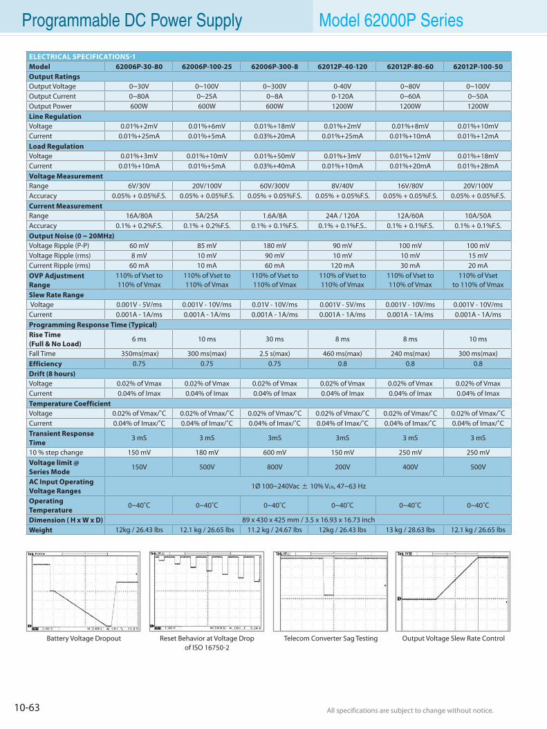
10-63 All specifications are subject to change without notice. All specifications are subject to change without notice.
Programmable DC Power Supply Model 62000P Series
ELECTRICAL SPECIFICATIONS-1Model 62006P-30-80 62006P-100-25 62006P-300-8 62012P-40-120 62012P-80-60 62012P-100-50Output RatingsOutput Voltage 0~30V 0~100V 0~300V 0-40V 0~80V 0~100VOutput Current 0~80A 0~25A 0~8A 0-120A 0~60A 0~50AOutput Power 600W 600W 600W 1200W 1200W 1200WLine Regulation Voltage 0.01%+2mV 0.01%+6mV 0.01%+18mV 0.01%+2mV 0.01%+8mV 0.01%+10mVCurrent 0.01%+25mA 0.01%+5mA 0.03%+20mA 0.01%+25mA 0.01%+10mA 0.01%+12mALoad RegulationVoltage 0.01%+3mV 0.01%+10mV 0.01%+50mV 0.01%+3mV 0.01%+12mV 0.01%+18mVCurrent 0.01%+10mA 0.01%+5mA 0.03%+40mA 0.01%+10mA 0.01%+20mA 0.01%+28mAVoltage MeasurementRange 6V/30V 20V/100V 60V/300V 8V/40V 16V/80V 20V/100VAccuracy 0.05% + 0.05%F.S. 0.05% + 0.05%F.S. 0.05% + 0.05%F.S. 0.05% + 0.05%F.S. 0.05% + 0.05%F.S. 0.05% + 0.05%F.S.Current MeasurementRange 16A/80A 5A/25A 1.6A/8A 24A / 120A 12A/60A 10A/50AAccuracy 0.1% + 0.2%F.S. 0.1% + 0.2%F.S. 0.1% + 0.1%F.S. 0.1% + 0.1%F.S.. 0.1% + 0.1%F.S. 0.1% + 0.1%F.S.Output Noise (0 ~ 20MHz) Voltage Ripple (P-P) 60 mV 85 mV 180 mV 90 mV 100 mV 100 mVVoltage Ripple (rms) 8 mV 10 mV 90 mV 10 mV 10 mV 15 mVCurrent Ripple (rms) 60 mA 10 mA 60 mA 120 mA 30 mA 20 mAOVP Adjustment Range
110% of Vset to 110% of Vmax
110% of Vset to 110% of Vmax
110% of Vset to 110% of Vmax
110% of Vset to 110% of Vmax
110% of Vset to 110% of Vmax
110% of Vset to 110% of Vmax
Slew Rate Range Voltage 0.001V - 5V/ms 0.001V - 10V/ms 0.01V - 10V/ms 0.001V - 5V/ms 0.001V - 10V/ms 0.001V - 10V/msCurrent 0.001A - 1A/ms 0.001A - 1A/ms 0.001A - 1A/ms 0.001A - 1A/ms 0.001A - 1A/ms 0.001A - 1A/msProgramming Response Time (Typical) Rise Time(Full & No Load)
6 ms 10 ms 30 ms 8 ms 8 ms 10 ms
Fall Time 350ms(max) 300 ms(max) 2.5 s(max) 460 ms(max) 240 ms(max) 300 ms(max)Efficiency 0.75 0.75 0.75 0.8 0.8 0.8Drift (8 hours)Voltage 0.02% of Vmax 0.02% of Vmax 0.02% of Vmax 0.02% of Vmax 0.02% of Vmax 0.02% of VmaxCurrent 0.04% of Imax 0.04% of Imax 0.04% of Imax 0.04% of Imax 0.04% of Imax 0.04% of ImaxTemperature CoefficientVoltage 0.02% of Vmax/˚C 0.02% of Vmax/˚C 0.02% of Vmax/˚C 0.02% of Vmax/˚C 0.02% of Vmax/˚C 0.02% of Vmax/˚CCurrent 0.04% of Imax/˚C 0.04% of Imax/˚C 0.04% of Imax/˚C 0.04% of Imax/˚C 0.04% of Imax/˚C 0.04% of Imax/˚CTransient Response Time
3 mS 3 mS 3mS 3mS 3 mS 3 mS
10 % step change 150 mV 180 mV 600 mV 150 mV 250 mV 250 mVVoltage limit @ Series Mode
150V 500V 800V 200V 400V 500V
AC Input OperatingVoltage Ranges
1Ø 100~240Vac ± 10% VLN, 47~63 Hz
Operating Temperature
0~40˚C 0~40˚C 0~40˚C 0~40˚C 0~40˚C 0~40˚C
Dimension ( H x W x D) 89 x 430 x 425 mm / 3.5 x 16.93 x 16.73 inchWeight 12kg / 26.43 lbs 12.1 kg / 26.65 lbs 11.2 kg / 24.67 lbs 12kg / 26.43 lbs 13 kg / 28.63 lbs 12.1 kg / 26.65 lbs
Reset Behavior at Voltage Dropof ISO 16750-2
Telecom Converter Sag Testing Output Voltage Slew Rate ControlBattery Voltage Dropout
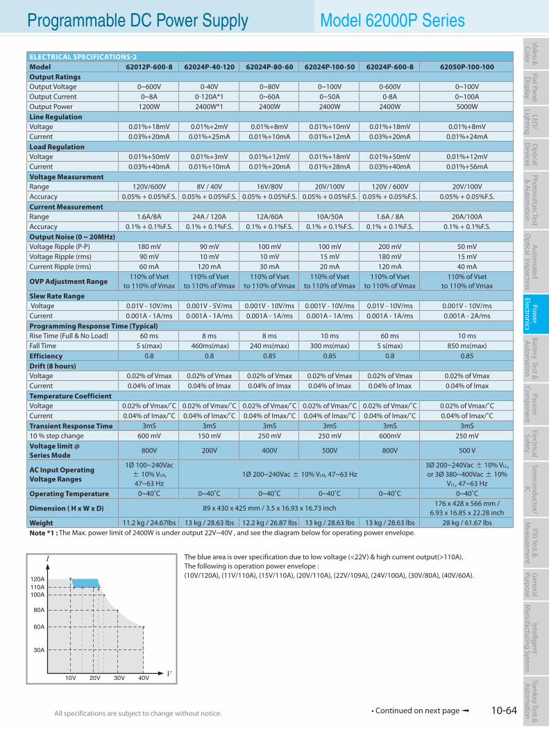
10-64All specifications are subject to change without notice. All specifications are subject to change without notice.
Flat PanelD
isplayPow
er Electronics
Electrical Safety
General
PurposePassive
Component
Semiconductor/
ICBattery Test & Autom
ationAutom
atedO
ptical Inspection Photovoltaic Test
& Automation
PXI Test &
Measurem
ent Video & Color
LED/
LightingO
ptical D
evicesIntelligent
Manufacturing System
Turnkey Test & Autom
ation Programmable DC Power Supply Model 62000P Series
ELECTRICAL SPECIFICATIONS-2Model 62012P-600-8 62024P-40-120 62024P-80-60 62024P-100-50 62024P-600-8 62050P-100-100Output RatingsOutput Voltage 0~600V 0-40V 0~80V 0~100V 0-600V 0~100VOutput Current 0~8A 0-120A*1 0~60A 0~50A 0-8A 0~100AOutput Power 1200W 2400W*1 2400W 2400W 2400W 5000WLine Regulation Voltage 0.01%+18mV 0.01%+2mV 0.01%+8mV 0.01%+10mV 0.01%+18mV 0.01%+8mV Current 0.03%+20mA 0.01%+25mA 0.01%+10mA 0.01%+12mA 0.03%+20mA 0.01%+24mALoad RegulationVoltage 0.01%+50mV 0.01%+3mV 0.01%+12mV 0.01%+18mV 0.01%+50mV 0.01%+12mVCurrent 0.03%+40mA 0.01%+10mA 0.01%+20mA 0.01%+28mA 0.03%+40mA 0.01%+56mAVoltage MeasurementRange 120V/600V 8V / 40V 16V/80V 20V/100V 120V / 600V 20V/100VAccuracy 0.05% + 0.05%F.S. 0.05% + 0.05%F.S. 0.05% + 0.05%F.S. 0.05% + 0.05%F.S. 0.05% + 0.05%F.S. 0.05% + 0.05%F.S.Current MeasurementRange 1.6A/8A 24A / 120A 12A/60A 10A/50A 1.6A / 8A 20A/100AAccuracy 0.1% + 0.1%F.S. 0.1% + 0.1%F.S. 0.1% + 0.1%F.S. 0.1% + 0.1%F.S. 0.1% + 0.1%F.S. 0.1% + 0.1%F.S.Output Noise (0 ~ 20MHz) Voltage Ripple (P-P) 180 mV 90 mV 100 mV 100 mV 200 mV 50 mVVoltage Ripple (rms) 90 mV 10 mV 10 mV 15 mV 180 mV 15 mVCurrent Ripple (rms) 60 mA 120 mA 30 mA 20 mA 120 mA 40 mA
OVP Adjustment Range110% of Vset
to 110% of Vmax110% of Vset
to 110% of Vmax110% of Vset
to 110% of Vmax110% of Vset
to 110% of Vmax110% of Vset
to 110% of Vmax110% of Vset
to 110% of VmaxSlew Rate Range Voltage 0.01V - 10V/ms 0.001V - 5V/ms 0.001V - 10V/ms 0.001V - 10V/ms 0.01V - 10V/ms 0.001V - 10V/msCurrent 0.001A - 1A/ms 0.001A - 1A/ms 0.001A - 1A/ms 0.001A - 1A/ms 0.001A - 1A/ms 0.001A - 2A/msProgramming Response Time (Typical) Rise Time (Full & No Load) 60 ms 8 ms 8 ms 10 ms 60 ms 10 msFall Time 5 s(max) 460ms(max) 240 ms(max) 300 ms(max) 5 s(max) 850 ms(max)Efficiency 0.8 0.8 0.85 0.85 0.8 0.85Drift (8 hours)Voltage 0.02% of Vmax 0.02% of Vmax 0.02% of Vmax 0.02% of Vmax 0.02% of Vmax 0.02% of VmaxCurrent 0.04% of Imax 0.04% of Imax 0.04% of Imax 0.04% of Imax 0.04% of Imax 0.04% of ImaxTemperature CoefficientVoltage 0.02% of Vmax/˚C 0.02% of Vmax/˚C 0.02% of Vmax/˚C 0.02% of Vmax/˚C 0.02% of Vmax/˚C 0.02% of Vmax/˚CCurrent 0.04% of Imax/˚C 0.04% of Imax/˚C 0.04% of Imax/˚C 0.04% of Imax/˚C 0.04% of Imax/˚C 0.04% of Imax/˚CTransient Response Time 3mS 3mS 3mS 3mS 3mS 3mS10 % step change 600 mV 150 mV 250 mV 250 mV 600mV 250 mVVoltage limit @Series Mode
800V 200V 400V 500V 800V 500 V
AC Input OperatingVoltage Ranges
1Ø 100~240Vac ± 10% VLN, 47~63 Hz
1Ø 200~240Vac ± 10% VLN, 47~63 Hz3Ø 200~240Vac ± 10% VLL, or 3Ø 380~400Vac ± 10%
VLL, 47~63 HzOperating Temperature 0~40˚C 0~40˚C 0~40˚C 0~40˚C 0~40˚C 0~40˚C
Dimension ( H x W x D) 89 x 430 x 425 mm / 3.5 x 16.93 x 16.73 inch176 x 428 x 566 mm /
6.93 x 16.85 x 22.28 inchWeight 11.2 kg / 24.67lbs 13 kg / 28.63 lbs 12.2 kg / 26.87 lbs 13 kg / 28.63 lbs 13 kg / 28.63 lbs 28 kg / 61.67 lbsNote *1 : The Max. power limit of 2400W is under output 22V~40V , and see the diagram below for operating power envelope.
The blue area is over specification due to low voltage (<22V) & high current output(>110A).The following is operation power envelope :(10V/120A), (11V/110A), (15V/110A), (20V/110A), (22V/109A), (24V/100A), (30V/80A), (40V/60A).
• Continued on next page
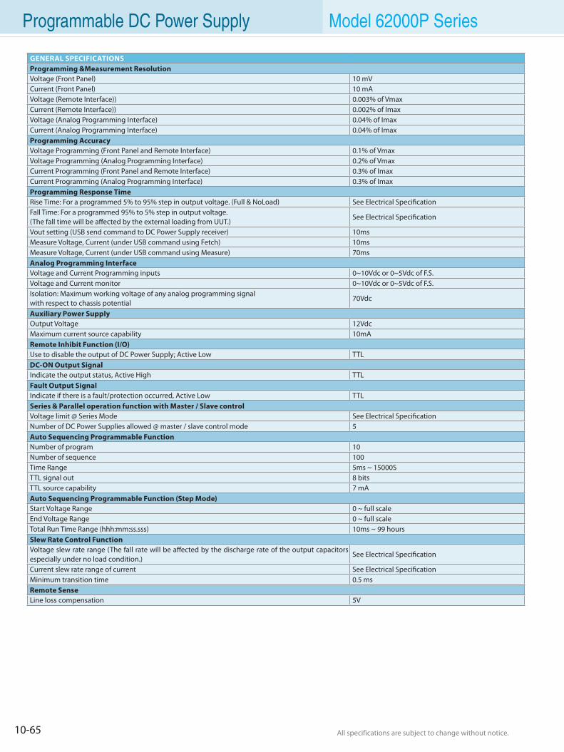
10-65 All specifications are subject to change without notice. All specifications are subject to change without notice.
Programmable DC Power Supply Model 62000P Series
GENERAL SPECIFICATIONSProgramming &Measurement ResolutionVoltage (Front Panel) 10 mVCurrent (Front Panel) 10 mAVoltage (Remote Interface)) 0.003% of VmaxCurrent (Remote Interface)) 0.002% of ImaxVoltage (Analog Programming Interface) 0.04% of ImaxCurrent (Analog Programming Interface) 0.04% of ImaxProgramming Accuracy Voltage Programming (Front Panel and Remote Interface) 0.1% of VmaxVoltage Programming (Analog Programming Interface) 0.2% of VmaxCurrent Programming (Front Panel and Remote Interface) 0.3% of ImaxCurrent Programming (Analog Programming Interface) 0.3% of ImaxProgramming Response TimeRise Time: For a programmed 5% to 95% step in output voltage. (Full & NoLoad) See Electrical SpecificationFall Time: For a programmed 95% to 5% step in output voltage.(The fall time will be affected by the external loading from UUT.)
See Electrical Specification
Vout setting (USB send command to DC Power Supply receiver) 10msMeasure Voltage, Current (under USB command using Fetch) 10msMeasure Voltage, Current (under USB command using Measure) 70msAnalog Programming Interface Voltage and Current Programming inputs 0~10Vdc or 0~5Vdc of F.S. Voltage and Current monitor 0~10Vdc or 0~5Vdc of F.S. Isolation: Maximum working voltage of any analog programming signalwith respect to chassis potential
70Vdc
Auxiliary Power SupplyOutput Voltage 12VdcMaximum current source capability 10mARemote Inhibit Function (I/O)Use to disable the output of DC Power Supply; Active Low TTLDC-ON Output SignalIndicate the output status, Active High TTLFault Output Signal Indicate if there is a fault/protection occurred, Active Low TTLSeries & Parallel operation function with Master / Slave controlVoltage limit @ Series Mode See Electrical SpecificationNumber of DC Power Supplies allowed @ master / slave control mode 5Auto Sequencing Programmable FunctionNumber of program 10Number of sequence 100Time Range 5ms ~ 15000STTL signal out 8 bitsTTL source capability 7 mAAuto Sequencing Programmable Function (Step Mode)Start Voltage Range 0 ~ full scaleEnd Voltage Range 0 ~ full scaleTotal Run Time Range (hhh:mm:ss.sss) 10ms ~ 99 hoursSlew Rate Control FunctionVoltage slew rate range (The fall rate will be affected by the discharge rate of the output capacitors especially under no load condition.)
See Electrical Specification
Current slew rate range of current See Electrical SpecificationMinimum transition time 0.5 msRemote SenseLine loss compensation 5V
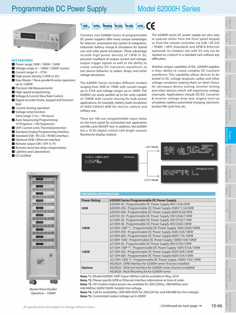
10-66All specifications are subject to change without notice. All specifications are subject to change without notice.
Flat PanelD
isplayPow
er Electronics
Electrical Safety
General
PurposePassive
Component
Semiconductor/
ICBattery Test & Autom
ationAutom
atedO
ptical Inspection Photovoltaic Test
& Automation
PXI Test &
Measurem
ent Video & Color
LED/
LightingO
ptical D
evicesIntelligent
Manufacturing System
Turnkey Test & Autom
ation Programmable DC Power Supply Model 62000H Series
KEY FEATURES Power range: 5KW / 10KW / 15KW Voltage range: 0 ~ 1000V / 2000V (series) Current range: 0 ~ 375A High power density (15KW in 3U) Easy Master / Slave parallel & series operation up to 150KW Precision V&I Measurements High-speed programming Voltage & Current Slew Rate Control Digital encoder knobs, keypad and function keys Current sharing operation Voltage ramp function (time range: 5 ms ~ 99 hours) Auto Sequencing Programming: 10 Programs / 100 Sequences OVP, Current Limit, Thermal protection Standard Analog Programming interface Standard USB / RS-232 / RS485 interface Optional GPIB / Ethernet interface Remote output ON / OFF (I / P) Remote sense line drop compensation LabView and Labwindows CE Certified
Chroma's new 62000H Series of programmable DC power supplies offer many unique advantages for telecom, automated test system & integration, industrial, battery charge & simulation for hybrid cars and solar panel simulation. These advantage include high power density of 15KW in 3U, precision readback of output current and voltage, output trigger signals as well as the ability to create complex DC t ransients waveforms to test device behavior to spikes, drops, and other voltage deviations.
The 62000H Series includes different models ranging from 5KW to 15KW, with current ranges up to 375A and voltage ranges up to 1000V. The 62000H can easily parallel up to ten units capable of 150KW with current sharing for bulk power applications, for example, battery bank simulation of 450V/150A/67.5KW for electric vehicle and military use.
There are 100 user programmable input status on the front panel for automated test application and life cycle ON/OFF test. In addition, the 62000H has a 16 bit digital control with bright vacuum fluorescent display readout.
The 62000H series DC power supply are very easy to operate either from the front panel keypad or from the remote controller via USB / RS-232 / RS485 / APG (Standard) and GPIB & Ethernet (optional). Its compact size with 3U only can be stacked on a bench in a standard rack without any difficulties.
Another unique capability of the 62000H supplies is their ability to create complex DC transient waveforms. This capability allows devices to be tested to DC voltage dropouts, spikes and other voltage variations making them an ideal choice for aerospace device testing, inverter testing and other devices which will experience voltage interrupts. Applications include DC/DC Converter & Inverter voltage drop test, engine start-up simulation, battery automated charging, electronic product life cycle test, etc.
Master/Slave ParallelOperation - 150kW
ORDERING INFORMATION
Power Rating 62000H Series Programmable DC Power Supply
5KW62050H-40 : Programmable DC Power Supply 40V/125A/5KW62050H-450 : Programmable DC Power Supply 450V/11.5A/5KW62050H-600 : Programmable DC Power Supply 600V/8.5A/5KW
10KW
62075H-30 : Programmable DC Power Supply 30V/250A/7.5KW62100H-30 : Programmable DC Power Supply 30V/375A/11KW62100H-40 : Programmable DC Power Supply 40V/250A/10KW62100H-100P *1 : Programmable DC Power Supply 100V/250A/10KW62100H-450 : Programmable DC Power Supply 450V/23A/10KW62100H-600 : Programmable DC Power Supply 600V/17A/10KW62100H-1000 : Programmable DC Power Supply 1000V/10A/10KW
15KW
62150H-40 : Programmable DC Power Supply 40V/375A/15KW62150H-100P *1 : Programmable DC Power Supply 100V/375A/15KW62150H-450 : Programmable DC Power Supply 450V/34A/15KW62150H-600 : Programmable DC Power Supply 600V/25A/15KW 62150H-1000 *5 : Programmable DC Power Supply 1000V/15A/15KW
OptionsA620024 : GPIB Interface for 62000H series (Factory installed)A620025 : Ethernet Interface for 62000H series (Factory installed)A620026 : Rack Mounting kit for 62000H series
Note *1 : Model 62000H-100P (input 380Vac) will be available in May, 2016Note *2 : Please specify GPIB or Ethernet Interface (alternative) at time of order.Note *3 : All models output power are available for 200/220Vac, 380/400Vac and 440/480Vac (600V/1000V models) line voltage.Note *4 : Call for availability. (30V/40V/450V for 200/220 Vac and 440/480 Vac line voltage)Note *5 : Customized output voltage up to 2000V
• Continued on next page
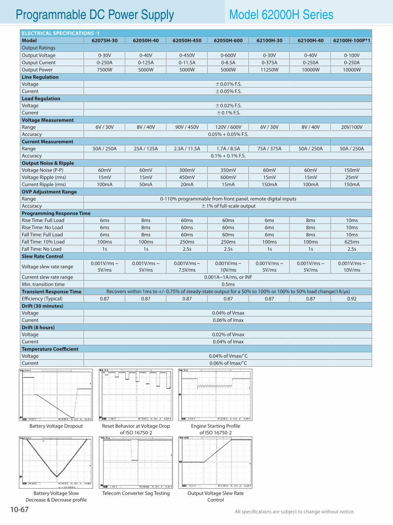
10-67 All specifications are subject to change without notice. All specifications are subject to change without notice.
Programmable DC Power Supply Model 62000H Series
Reset Behavior at Voltage Dropof ISO 16750-2
Engine Starting Profileof ISO 16750-2
Telecom Converter Sag Testing Output Voltage Slew Rate Control
Battery Voltage Dropout
Battery Voltage SlowDecrease & Decrease profile
ELECTRICAL SPECIFICATIONS -1Model 62075H-30 62050H-40 62050H-450 62050H-600 62100H-30 62100H-40 62100H-100P*1Output RatingsOutput Voltage 0-30V 0-40V 0-450V 0-600V 0-30V 0-40V 0-100VOutput Current 0-250A 0-125A 0-11.5A 0-8.5A 0-375A 0-250A 0-250AOutput Power 7500W 5000W 5000W 5000W 11250W 10000W 10000WLine RegulationVoltage ±0.01% F.S.Current ±0.05% F.S.Load RegulationVoltage ±0.02% F.S.Current ±0.1% F.S.Voltage MeasurementRange 6V / 30V 8V / 40V 90V / 450V 120V / 600V 6V / 30V 8V / 40V 20V/100VAccuracy 0.05% + 0.05% F.S.Current MeasurementRange 50A / 250A 25A / 125A 2.3A / 11.5A 1.7A / 8.5A 75A / 375A 50A / 250A 50A / 250AAccuracy 0.1% + 0.1% F.S.Output Noise & RippleVoltage Noise (P-P) 60mV 60mV 300mV 350mV 60mV 60mV 150mVVoltage Ripple (rms) 15mV 15mV 450mV 600mV 15mV 15mV 25mVCurrent Ripple (rms) 100mA 50mA 20mA 15mA 150mA 100mA 150mAOVP Adjustment RangeRange 0-110% programmable from front panel, remote digital inputsAccuracy ±1% of full-scale outputProgramming Response TimeRise Time: Full Load 6ms 8ms 60ms 60ms 6ms 8ms 10msRise Time: No Load 6ms 8ms 60ms 60ms 6ms 8ms 10msFall Time: Full Load 6ms 8ms 60ms 60ms 6ms 8ms 10ms Fall Time: 10% Load 100ms 100ms 250ms 250ms 100ms 100ms 625msFall Time: No Load 1s 1s 2.5s 2.5s 1s 1s 2.5sSlew Rate Control
Voltage slew rate range0.001V/ms ~
5V/ms0.001V/ms ~
5V/ms0.001V/ms ~
7.5V/ms0.001V/ms ~
10V/ms0.001V/ms ~
5V/ms0.001V/ms ~
5V/ms0.001V/ms ~
10V/msCurrent slew rate range 0.001A~1A/ms, or INFMin. transition time 0.5msTransient Response Time Recovers within 1ms to +/- 0.75% of steady-state output for a 50% to 100% or 100% to 50% load change(1A/µs)Efficiency (Typical) 0.87 0.87 0.87 0.87 0.87 0.87 0.92Drift (30 minutes)Voltage 0.04% of VmaxCurrent 0.06% of ImaxDrift (8 hours)Voltage 0.02% of VmaxCurrent 0.04% of ImaxTemperature CoefficientVoltage 0.04% of Vmax/˚CCurrent 0.06% of Imax/˚C
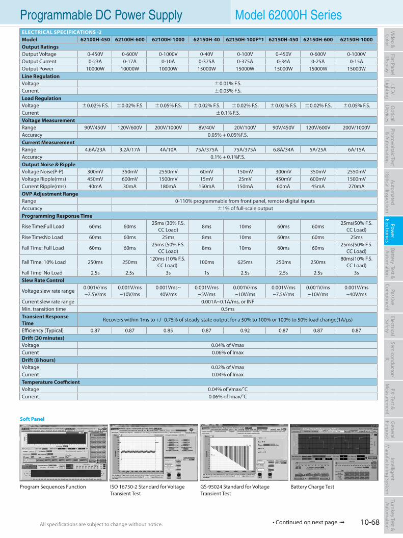
10-68All specifications are subject to change without notice. All specifications are subject to change without notice.
Flat PanelD
isplayPow
er Electronics
Electrical Safety
General
PurposePassive
Component
Semiconductor/
ICBattery Test & Autom
ationAutom
atedO
ptical Inspection Photovoltaic Test
& Automation
PXI Test &
Measurem
ent Video & Color
LED/
LightingO
ptical D
evicesIntelligent
Manufacturing System
Turnkey Test & Autom
ation Programmable DC Power Supply Model 62000H SeriesELECTRICAL SPECIFICATIONS -2Model 62100H-450 62100H-600 62100H-1000 62150H-40 62150H-100P*1 62150H-450 62150H-600 62150H-1000Output RatingsOutput Voltage 0-450V 0-600V 0-1000V 0-40V 0-100V 0-450V 0-600V 0-1000VOutput Current 0-23A 0-17A 0-10A 0-375A 0-375A 0-34A 0-25A 0-15AOutput Power 10000W 10000W 10000W 15000W 15000W 15000W 15000W 15000WLine RegulationVoltage ±0.01% F.S.Current ±0.05% F.S.Load RegulationVoltage ±0.02% F.S. ±0.02% F.S. ±0.05% F.S. ±0.02% F.S. ±0.02% F.S. ±0.02% F.S. ±0.02% F.S. ±0.05% F.S.Current ±0.1% F.S.Voltage MeasurementRange 90V/450V 120V/600V 200V/1000V 8V/40V 20V/100V 90V/450V 120V/600V 200V/1000VAccuracy 0.05% + 0.05%F.S.Current MeasurementRange 4.6A/23A 3.2A/17A 4A/10A 75A/375A 75A/375A 6.8A/34A 5A/25A 6A/15AAccuracy 0.1% + 0.1%F.S.Output Noise & RippleVoltage Noise(P-P) 300mV 350mV 2550mV 60mV 150mV 300mV 350mV 2550mVVoltage Ripple(rms) 450mV 600mV 1500mV 15mV 25mV 450mV 600mV 1500mVCurrent Ripple(rms) 40mA 30mA 180mA 150mA 150mA 60mA 45mA 270mAOVP Adjustment RangeRange 0-110% programmable from front panel, remote digital inputsAccuracy ±1% of full-scale outputProgramming Response Time
Rise Time:Full Load 60ms 60ms25ms (30% F.S.
CC Load)8ms 10ms 60ms 60ms
25ms(50% F.S. CC Load)
Rise Time:No Load 60ms 60ms 25ms 8ms 10ms 60ms 60ms 25ms
Fall Time: Full Load 60ms 60ms 25ms (50% F.S.
CC Load)8ms 10ms 60ms 60ms
25ms(50% F.S. CC Load)
Fall Time: 10% Load 250ms 250ms120ms (10% F.S.
CC Load)100ms 625ms 250ms 250ms
80ms(10% F.S. CC Load)
Fall Time: No Load 2.5s 2.5s 3s 1s 2.5s 2.5s 2.5s 3sSlew Rate Control
Voltage slew rate range0.001V/ms ~7.5V/ms
0.001V/ms~10V/ms
0.001Vms~40V/ms
0.001V/ms~5V/ms
0.001V/ms~10V/ms
0.001V/ms~7.5V/ms
0.001V/ms~10V/ms
0.001V/ms~40V/ms
Current slew rate range 0.001A~0.1A/ms, or INFMin. transition time 0.5msTransient Response Time
Recovers within 1ms to +/- 0.75% of steady-state output for a 50% to 100% or 100% to 50% load change(1A/µs)
Efficiency (Typical) 0.87 0.87 0.85 0.87 0.92 0.87 0.87 0.87Drift (30 minutes)Voltage 0.04% of VmaxCurrent 0.06% of ImaxDrift (8 hours)Voltage 0.02% of VmaxCurrent 0.04% of ImaxTemperature CoefficientVoltage 0.04% of Vmax/˚CCurrent 0.06% of Imax/˚C
Soft Panel
Program Sequences Function ISO 16750-2 Standard for Voltage Transient Test
GS-95024 Standard for Voltage Transient Test
Battery Charge Test
• Continued on next page
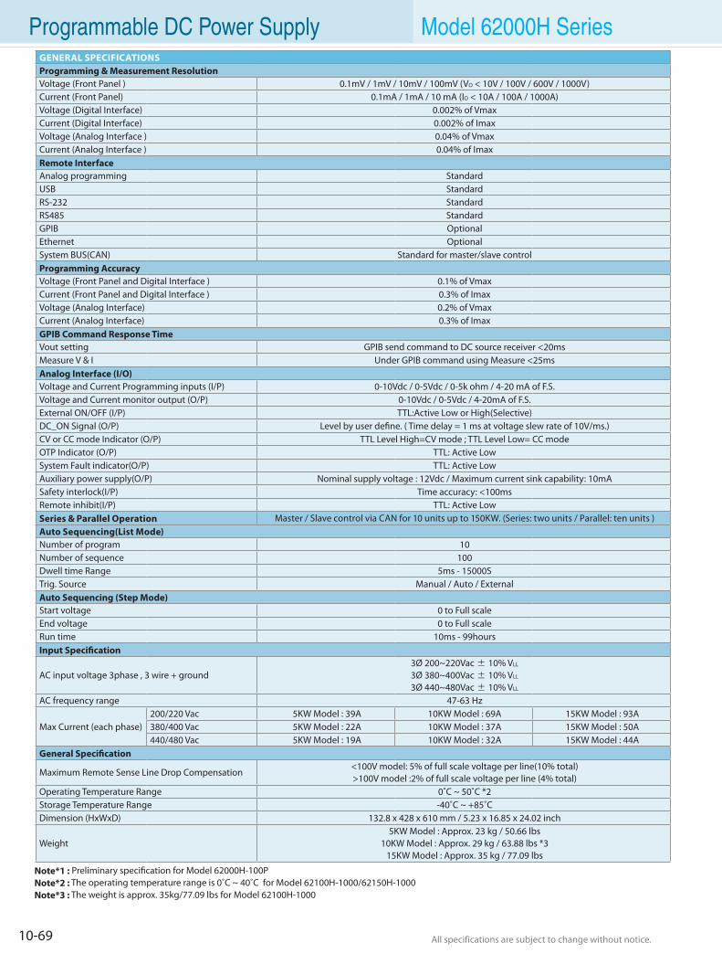
10-69 All specifications are subject to change without notice. All specifications are subject to change without notice.
Programmable DC Power Supply Model 62000H SeriesGENERAL SPECIFICATIONSProgramming & Measurement ResolutionVoltage (Front Panel ) 0.1mV / 1mV / 10mV / 100mV (VO < 10V / 100V / 600V / 1000V)Current (Front Panel) 0.1mA / 1mA / 10 mA (IO < 10A / 100A / 1000A)Voltage (Digital Interface) 0.002% of VmaxCurrent (Digital Interface) 0.002% of ImaxVoltage (Analog Interface ) 0.04% of VmaxCurrent (Analog Interface ) 0.04% of ImaxRemote InterfaceAnalog programming StandardUSB StandardRS-232 StandardRS485 StandardGPIB OptionalEthernet OptionalSystem BUS(CAN) Standard for master/slave controlProgramming AccuracyVoltage (Front Panel and Digital Interface ) 0.1% of VmaxCurrent (Front Panel and Digital Interface ) 0.3% of ImaxVoltage (Analog Interface) 0.2% of VmaxCurrent (Analog Interface) 0.3% of ImaxGPIB Command Response TimeVout setting GPIB send command to DC source receiver <20msMeasure V & I Under GPIB command using Measure <25msAnalog Interface (I/O)Voltage and Current Programming inputs (I/P) 0-10Vdc / 0-5Vdc / 0-5k ohm / 4-20 mA of F.S.Voltage and Current monitor output (O/P) 0-10Vdc / 0-5Vdc / 4-20mA of F.S.External ON/OFF (I/P) TTL:Active Low or High(Selective)DC_ON Signal (O/P) Level by user define. ( Time delay = 1 ms at voltage slew rate of 10V/ms.)CV or CC mode Indicator (O/P) TTL Level High=CV mode ; TTL Level Low= CC modeOTP Indicator (O/P) TTL: Active LowSystem Fault indicator(O/P) TTL: Active LowAuxiliary power supply(O/P) Nominal supply voltage : 12Vdc / Maximum current sink capability: 10mASafety interlock(I/P) Time accuracy: <100msRemote inhibit(I/P) TTL: Active LowSeries & Parallel Operation Master / Slave control via CAN for 10 units up to 150KW. (Series: two units / Parallel: ten units )Auto Sequencing(List Mode)Number of program 10Number of sequence 100Dwell time Range 5ms - 15000STrig. Source Manual / Auto / ExternalAuto Sequencing (Step Mode)Start voltage 0 to Full scaleEnd voltage 0 to Full scaleRun time 10ms - 99hoursInput Specification
AC input voltage 3phase , 3 wire + ground3Ø 200~220Vac ± 10% VLL
3Ø 380~400Vac ± 10% VLL
3Ø 440~480Vac ± 10% VLL
AC frequency range 47-63 Hz
Max Current (each phase)200/220 Vac 5KW Model : 39A 10KW Model : 69A 15KW Model : 93A380/400 Vac 5KW Model : 22A 10KW Model : 37A 15KW Model : 50A440/480 Vac 5KW Model : 19A 10KW Model : 32A 15KW Model : 44A
General Specification
Maximum Remote Sense Line Drop Compensation<100V model: 5% of full scale voltage per line(10% total)>100V model :2% of full scale voltage per line (4% total)
Operating Temperature Range 0˚C ~ 50˚C *2Storage Temperature Range -40˚C ~ +85˚CDimension (HxWxD) 132.8 x 428 x 610 mm / 5.23 x 16.85 x 24.02 inch
Weight5KW Model : Approx. 23 kg / 50.66 lbs
10KW Model : Approx. 29 kg / 63.88 lbs *315KW Model : Approx. 35 kg / 77.09 lbs
Note*1 : Preliminary specification for Model 62000H-100PNote*2 : The operating temperature range is 0˚C ~ 40˚C for Model 62100H-1000/62150H-1000Note*3 : The weight is approx. 35kg/77.09 lbs for Model 62100H-1000
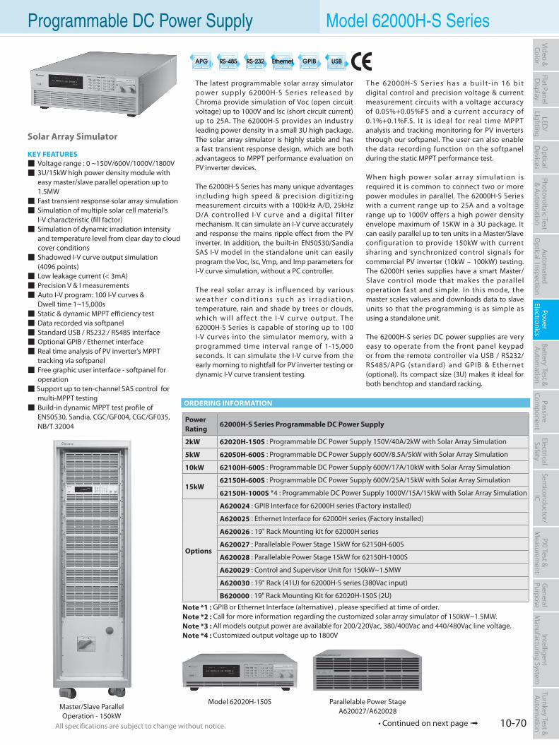
10-70All specifications are subject to change without notice. All specifications are subject to change without notice.
Flat PanelD
isplayPow
er Electronics
Electrical Safety
General
PurposePassive
Component
Semiconductor/
ICBattery Test & Autom
ationAutom
atedO
ptical Inspection Photovoltaic Test
& Automation
PXI Test &
Measurem
ent Video & Color
LED/
LightingO
ptical D
evicesIntelligent
Manufacturing System
Turnkey Test & Autom
ation Programmable DC Power Supply Model 62000H-S Series
Solar Array Simulator
KEY FEATURES Voltage range : 0 ~150V/600V/1000V/1800V 3U/15kW high power density module with easy master/slave parallel operation up to 1.5MW Fast transient response solar array simulation Simulation of multiple solar cell material's I-V characteristic (fill factor) Simulation of dynamic irradiation intensity and temperature level from clear day to cloud cover conditions Shadowed I-V curve output simulation (4096 points) Low leakage current (< 3mA) Precision V & I measurements Auto I-V program: 100 I-V curves & Dwell time 1~15,000s Static & dynamic MPPT efficiency test Data recorded via softpanel Standard USB / RS232 / RS485 interface Optional GPIB / Ethernet interface Real time analysis of PV inverter's MPPT tracking via softpanel Free graphic user interface - softpanel for operation Support up to ten-channel SAS control for multi-MPPT testing Build-in dynamic MPPT test profile of EN50530, Sandia, CGC/GF004, CGC/GF035, NB/T 32004
The latest programmable solar array simulator power supply 62000H-S Series released by Chroma provide simulation of Voc (open circuit voltage) up to 1000V and Isc (short circuit current) up to 25A. The 62000H-S provides an industry leading power density in a small 3U high package. The solar array simulator is highly stable and has a fast transient response design, which are both advantageos to MPPT performance evaluation on PV inverter devices.
The 62000H-S Series has many unique advantages including high speed & precision digitizing measurement circuits with a 100kHz A/D, 25kHz D/A controlled I-V curve and a digital fi lter mechanism. It can simulate an I-V curve accurately and response the mains ripple effect from the PV inverter. In addition, the built-in EN50530/Sandia SAS I-V model in the standalone unit can easily program the Voc, Isc, Vmp, and Imp parameters for I-V curve simulation, without a PC controller.
The real solar array is influenced by various w e a t h e r c o n d i t i o n s s u c h a s i r r a d i a t i o n, temperature, rain and shade by trees or clouds, which wil l affect the I-V cur ve output. The 62000H-S Series is capable of storing up to 100 I-V curves into the simulator memory, with a programmed time interval range of 1-15,000 seconds. It can simulate the I-V curve from the early morning to nightfall for PV inverter testing or dynamic I-V curve transient testing.
Th e 62000H-S S e r i e s h a s a b u i l t-i n 16 b i t digital control and precision voltage & current measurement circuits with a voltage accuracy of 0.05%+0.05%FS and a current accuracy of 0.1%+0.1%F.S. I t is ideal for real time MPPT analysis and tracking monitoring for PV inverters through our softpanel. The user can also enable the data recording function on the softpanel during the static MPPT performance test.
When high power solar array simulation is required it is common to connect two or more power modules in parallel. The 62000H-S Series with a current range up to 25A and a voltage range up to 1000V offers a high power density envelope maximum of 15KW in a 3U package. It can easily parallel up to ten units in a Master/Slave configuration to provide 150kW with current sharing and synchronized control signals for commercial PV inverter (10kW – 100kW) testing. The 62000H series supplies have a smart Master/Slave control mode that makes the parallel operation fast and simple. In this mode, the master scales values and downloads data to slave units so that the programming is as simple as using a standalone unit.
The 62000H-S series DC power supplies are very easy to operate from the front panel keypad or from the remote controller via USB / RS232/ RS485/APG (standard) and GPIB & Ethernet (optional). Its compact size (3U) makes it ideal for both benchtop and standard racking.
ORDERING INFORMATION
Note *1 : GPIB or Ethernet Interface (alternative) , please specified at time of order.Note *2 : Call for more information regarding the customized solar array simulator of 150kW~1.5MW.Note *3 : All models output power are available for 200/220Vac, 380/400Vac and 440/480Vac line voltage.Note *4 : Customized output voltage up to 1800V
Master/Slave ParallelOperation - 150kW
PowerRating
62000H-S Series Programmable DC Power Supply
2kW 62020H-150S : Programmable DC Power Supply 150V/40A/2kW with Solar Array Simulation
5kW 62050H-600S : Programmable DC Power Supply 600V/8.5A/5kW with Solar Array Simulation
10kW 62100H-600S : Programmable DC Power Supply 600V/17A/10kW with Solar Array Simulation
15kW62150H-600S : Programmable DC Power Supply 600V/25A/15kW with Solar Array Simulation
62150H-1000S *4 : Programmable DC Power Supply 1000V/15A/15kW with Solar Array Simulation
Options
A620024 : GPIB Interface for 62000H series (Factory installed)
A620025 : Ethernet Interface for 62000H series (Factory installed)
A620026 : 19" Rack Mounting kit for 62000H series
A620027 : Parallelable Power Stage 15kW for 62150H-600S
A620028 : Parallelable Power Stage 15kW for 62150H-1000S
A620029 : Control and Supervisor Unit for 150kW~1.5MW
A620030 : 19" Rack (41U) for 62000H-S series (380Vac input)
B620000 : 19" Rack Mounting Kit for 62020H-150S (2U)
Model 62020H-150S Parallelable Power StageA620027/A620028
• Continued on next page
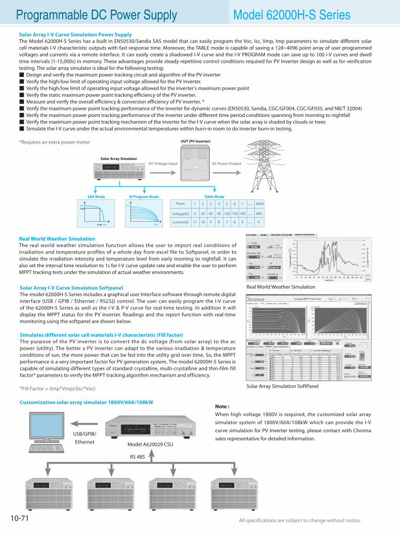
10-71 All specifications are subject to change without notice. All specifications are subject to change without notice.
Programmable DC Power Supply Model 62000H-S Series
Solar Array I-V Curve Simulation SoftpanelThe model 62000H-S Series includes a graphical user Interface software through remote digital interface (USB / GPIB / Ethernet / RS232) control. The user can easily program the I-V curve of the 62000H-S Series as well as the I-V & P-V curve for real-time testing. In addition it will display the MPPT status for the PV inverter. Readings and the report function with real-time monitoring using the softpanel are shown below.
Simulates different solar cell materials I-V characteristic (Fill factor)The purpose of the PV inverter is to convert the dc voltage (from solar array) to the ac power (utility). The better a PV inverter can adapt to the various irradiation & temperature conditions of sun, the more power that can be fed into the utility grid over time. So, the MPPT performance is a very important factor for PV generation system. The model 62000H-S Series is capable of simulating different types of standard crystalline, multi-crystalline and thin-film fill factor* parameters to verify the MPPT tracking algorithm mechanism and efficiency.
*Fill Factor = (Imp*Vmp)/(Isc*Voc)
Customization solar array simulator 1800V/60A/108kW
Solar Array Simulation SoftPanel
Solar Array Simulator
UUT (PV Inverter)
SAS Mode IV Program Mode Table Mode
DC Voltage Input AC Power Output
Isc
Vmp Voc
ImpIsc
Voc
Point 1
0
11
2
30
10
3
60
9
4
90
8
5
120
7
6
150
6
7
180
5
4096
600
0
.......
.......
.......
Voltage(V)
Current(A)
Solar Array I-V Curve Simulation Power SupplyThe Model 62000H-S Series has a built in EN50530/Sandia SAS model that can easily program the Voc, Isc, Vmp, Imp parameters to simulate different solar cell materials I-V characteristic outputs with fast response time. Moreover, the TABLE mode is capable of saving a 128~4096 point array of user programmed voltages and currents via a remote interface. It can easily create a shadowed I-V curve and the I-V PROGRAM mode can save up to 100 I-V curves and dwell time intervals (1-15,000s) in memory. These advantages provide steady repetitive control conditions required for PV Inverter design as well as for verification testing. The solar array simulator is ideal for the following testing: Design and verify the maximum power tracking circuit and algorithm of the PV inverter Verify the high/low limit of operating input voltage allowed for the PV inverter. Verify the high/low limit of operating input voltage allowed for the inverter's maximum power point Verify the static maximum power point tracking efficiency of the PV inverter. Measure and verify the overall efficiency & conversion efficiency of PV inverter. * Verify the maximum power point tracking performance of the inverter for dynamic curves (EN50530, Sandia, CGC/GF004, CGC/GF035, and NB/T 32004) Verify the maximum power point tracking performance of the inverter under different time period conditions spanning from morning to nightfall Verify the maximum power point tracking mechanism of the inverter for the I-V curve when the solar array is shaded by clouds or trees Simulate the I-V curve under the actual environmental temperatures within burn-in room to do inverter burn-in testing.
*Requires an extra power meter
Real World Waether SimulationThe real world weather simulation function allows the user to import real conditions of irradiation and temperature profiles of a whole day from excel file to Softpanel, in order to simulate the irradiation intensity and temperature level from early morning to nightfall. It can also set the interval time resolution to 1s for I-V curve update rate and enable the user to perform MPPT tracking tests under the simulation of actual weather environments.
Real World Weather Simulation
Model A620029 CSU
RS 485
USB/GPIB/Ethernet
Note : When high voltage 1800V is required, the customized solar array simulator system of 1800V/60A/108kW which can provide the I-V curve simulation for PV Inverter testing, please contact with Chroma sales representative for detailed information.
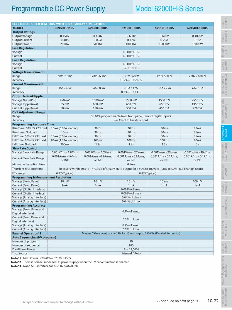
10-72All specifications are subject to change without notice. All specifications are subject to change without notice.
Flat PanelD
isplayPow
er Electronics
Electrical Safety
General
PurposePassive
Component
Semiconductor/
ICBattery Test & Autom
ationAutom
atedO
ptical Inspection Photovoltaic Test
& Automation
PXI Test &
Measurem
ent Video & Color
LED/
LightingO
ptical D
evicesIntelligent
Manufacturing System
Turnkey Test & Autom
ation Programmable DC Power Supply Model 62000H-S Series
ELECTRICAL SPECIFICATIONS-WITH SOLAR ARRAY SIMULATION MODEL 62020H-150S 62050H-600S 62100H-600S 62150H-600S 62150H-1000S Output RatingsOutput Voltage 0-150V 0-600V 0-600V 0-600V 0-1000VOutput Current 0-40A 0-8.5A 0-17A 0-25A 0-15AOutput Power 2000W 5000W 10000W 15000W 15000WLine RegulationVoltage +/- 0.01% F.S.Current +/- 0.05% F.S.Load RegulationVoltage +/- 0.05% F.S.Current +/- 0.1% F.S.Voltage MeasurementRange 60V / 150V 120V / 600V 120V / 600V 120V / 600V 200V / 1000VAccuracy 0.05% + 0.05%F.S.Current MeasurementRange 16A / 40A 3.4A / 8.5A 6.8A / 17A 10A / 25A 6A / 15AAccuracy 0.1% + 0.1%F.S.Output Noise&RippleVoltage Noise(P-P) 450 mV 1500 mV 1500 mV 1500 mV 2550 mVVoltage Ripple(rms) 65 mV 650 mV 650 mV 650 mV 1950 mVCurrent Ripple(rms) 80 mA 150 mA 300 mA 450 mA 270mAOVP Adjustment RangeRange 0-110% programmable from front panel, remote digital inputs. Accuracy +/- 1% of full-scale output Programming Response Time Rise Time: 50%F.S. CC Load 10ms (6.66A loading) 30ms 30ms 30ms 25msRise Time: No Load 10ms 30ms 30ms 30ms 25msFall Time: 50%F.S. CC Load 10ms (6.66A loading) 30ms 30ms 30ms 25msFall Time: 10%F.S. CC Load 83ms (1.33A loading) 100ms 100ms 100ms 80msFall Time: No Load 300ms 1.2s 1.2s 1.2s 3s Slew Rate Control Voltage Slew Rate Range 0.001V/ms - 15V/ms 0.001V/ms - 20V/ms 0.001V/ms - 20V/ms 0.001V/ms - 20V/ms 0.001V/ms - 40V/ms
Current Slew Rate Range0.001A/ms - 1A/ms,
or INF0.001A/ms - 0.1A/ms,
or INF0.001A/ms - 0.1A/ms,
or INF0.001A/ms - 0.1A/ms,
or INF0.001A/ms - 0.1A/ms,
or INFMinimum Transition Time 0.5msTransient response time Recovers within 1ms to +/- 0.75% of steady-state output for a 50% to 100% or 100% to 50% load change(1A/us)Efficiency 0.77 (Typical) 0.87 (Typical)Programming & Measurement ResolutionVoltage (Front Panel) 10 mV 10 mV 10 mV 10 mV 100mVCurrent (Front Panel) 1mA 1mA 1mA 1mA 1mAVoltage (Digital Interface) 0.002% of VmaxCurrent (Digital Interface) 0.002% of ImaxVoltage (Analog Interface) 0.04% of VmaxCurrent (Analog Interface) 0.04% of ImaxProgramming AccuracyVoltage (Front Panel and Digital Interface)
0.1% of Vmax
Current (Front Panel and Digital Interface)
0.3% of Imax
Voltage (Analog Interface) 0.2% of VmaxCurrent (Analog Interface) 0.3% of ImaxParallel Operation*1 Master / Slave control via CAN for 10 units up to 150KW. (Parallel: ten units )Auto Sequencing (I-V program)Number of program 10Number of sequence 100Dwell time Range 1s - 15,000STrig. Source Manual / Auto
Note*1 : Max. Power is 20kW for 62020H-150SNote*2 : There is parallel mode for DC power supply when the I-V curve function is enabledNote*3 : None APG interface for A620027/A620028
• Continued on next page
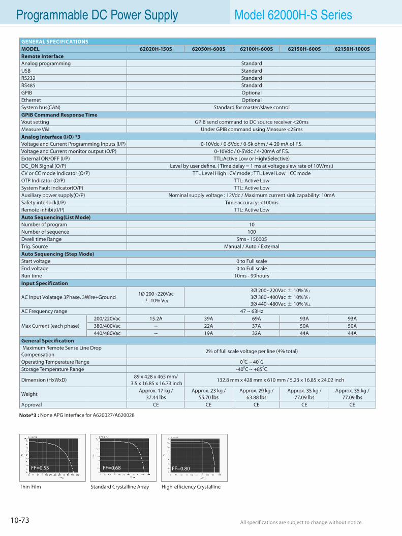
10-73 All specifications are subject to change without notice. All specifications are subject to change without notice.
Programmable DC Power Supply Model 62000H-S Series
GENERAL SPECIFICATIONSMODEL 62020H-150S 62050H-600S 62100H-600S 62150H-600S 62150H-1000SRemote InterfaceAnalog programming StandardUSB StandardRS232 StandardRS485 StandardGPIB OptionalEthernet OptionalSystem bus(CAN) Standard for master/slave controlGPIB Command Response TimeVout setting GPIB send command to DC source receiver <20msMeasure V&I Under GPIB command using Measure <25msAnalog Interface (I/O) *3Voltage and Current Programming Inputs (I/P) 0-10Vdc / 0-5Vdc / 0-5k ohm / 4-20 mA of F.S.Voltage and Current monitor output (O/P) 0-10Vdc / 0-5Vdc / 4-20mA of F.S.External ON/OFF (I/P) TTL:Active Low or High(Selective)DC_ON Signal (O/P) Level by user define. ( Time delay = 1 ms at voltage slew rate of 10V/ms.)CV or CC mode Indicator (O/P) TTL Level High=CV mode ; TTL Level Low= CC modeOTP Indicator (O/P) TTL: Active LowSystem Fault indicator(O/P) TTL: Active LowAuxiliary power supply(O/P) Nominal supply voltage : 12Vdc / Maximum current sink capability: 10mASafety interlock(I/P) Time accuracy: <100msRemote inhibit(I/P) TTL: Active LowAuto Sequencing(List Mode)Number of program 10Number of sequence 100Dwell time Range 5ms - 15000STrig. Source Manual / Auto / ExternalAuto Sequencing (Step Mode)Start voltage 0 to Full scaleEnd voltage 0 to Full scaleRun time 10ms - 99hoursInput Specification
AC Input Volatage 3Phase, 3Wire+Ground1Ø 200~220Vac± 10% VLN
3Ø 200~220Vac ± 10% VLL
3Ø 380~400Vac ± 10% VLL
3Ø 440~480Vac ± 10% VLL
AC Frequency range 47 ~ 63Hz
Max Current (each phase)200/220Vac 15.2A 39A 69A 93A 93A380/400Vac -- 22A 37A 50A 50A440/480Vac -- 19A 32A 44A 44A
General Specification Maximum Remote Sense Line Drop Compensation
2% of full scale voltage per line (4% total)
Operating Temperature Range 00C ~ 400CStorage Temperature Range -400C ~ +850C
Dimension (HxWxD)89 x 428 x 465 mm/
3.5 x 16.85 x 16.73 inch132.8 mm x 428 mm x 610 mm / 5.23 x 16.85 x 24.02 inch
WeightApprox. 17 kg /
37.44 lbsApprox. 23 kg /
55.70 lbsApprox. 29 kg /
63.88 lbs Approx. 35 kg /
77.09 lbs Approx. 35 kg /
77.09 lbs Approval CE CE CE CE CE
High-efficiency CrystallineStandard Crystalline ArrayThin-Film
FF=0.80FF=0.68FF=0.55
Note*3 : None APG interface for A620027/A620028
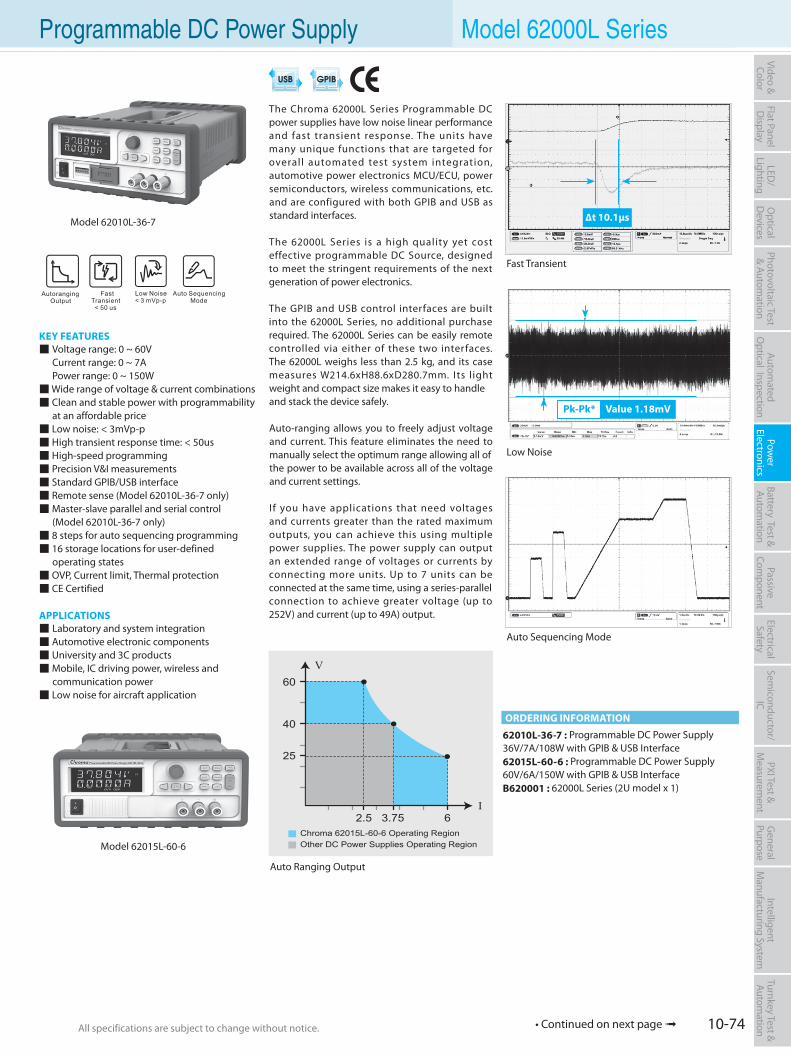
10-74All specifications are subject to change without notice. All specifications are subject to change without notice.
Flat PanelD
isplayPow
er Electronics
Electrical Safety
General
PurposePassive
Component
Semiconductor/
ICBattery Test & Autom
ationAutom
atedO
ptical Inspection Photovoltaic Test
& Automation
PXI Test &
Measurem
ent Video & Color
LED/
LightingO
ptical D
evicesIntelligent
Manufacturing System
Turnkey Test & Autom
ation
• Continued on next page
Programmable DC Power Supply Model 62000L Series
KEY FEATURES Voltage range: 0 ~ 60V Current range: 0 ~ 7A Power range: 0 ~ 150W Wide range of voltage & current combinations Clean and stable power with programmability at an affordable price Low noise: < 3mVp-p High transient response time: < 50us High-speed programming Precision V&I measurements Standard GPIB/USB interface Remote sense (Model 62010L-36-7 only) Master-slave parallel and serial control (Model 62010L-36-7 only) 8 steps for auto sequencing programming 16 storage locations for user-defined operating states OVP, Current limit, Thermal protection CE Certified
APPLICATIONS Laboratory and system integration Automotive electronic components University and 3C products Mobile, IC driving power, wireless and communication power Low noise for aircraft application
The Chroma 62000L Series Programmable DC power supplies have low noise linear performance and fast transient response. The units have many unique functions that are targeted for overall automated test system integration, automotive power electronics MCU/ECU, power semiconductors, wireless communications, etc. and are configured with both GPIB and USB as standard interfaces.
The 62000L Series is a high quality yet cost effective programmable DC Source, designed to meet the stringent requirements of the next generation of power electronics.
The GPIB and USB control interfaces are built into the 62000L Series, no additional purchase required. The 62000L Series can be easily remote controlled via either of these two interfaces. The 62000L weighs less than 2.5 kg, and its case measures W214.6xH88.6xD280.7mm. Its light weight and compact size makes it easy to handleand stack the device safely.
Auto-ranging allows you to freely adjust voltage and current. This feature eliminates the need to manually select the optimum range allowing all ofthe power to be available across all of the voltage and current settings.
If you have applications that need voltages and currents greater than the rated maximum outputs, you can achieve this using multiple power supplies. The power supply can output an extended range of voltages or currents by connecting more units. Up to 7 units can be connected at the same time, using a series-parallelconnection to achieve greater voltage (up to 252V) and current (up to 49A) output.
62010L-36-7 : Programmable DC Power Supply36V/7A/108W with GPIB & USB Interface62015L-60-6 : Programmable DC Power Supply60V/6A/150W with GPIB & USB InterfaceB620001 : 62000L Series (2U model x 1)
ORDERING INFORMATION
62.5
25
40
60
Other DC Power Supplies Operating RegionChroma 62015L-60-6 Operating Region
3.75I
V
Model 62015L-60-6
Fast Transient
Auto Sequencing Mode
Low Noise
∆t 10.1µs
Pk-Pk* Value 1.18mV
Auto Ranging Output
Model 62010L-36-7
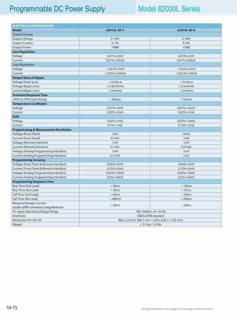
10-75 All specifications are subject to change without notice. All specifications are subject to change without notice.
Programmable DC Power Supply Model 62000L Series
ELECTRICAL SPECIFICATIONSModel 62010L-36-7 62015L-60-6Output RatingsOutput Voltage 0~36V 0~60VOutput Current 0~7A 0~6AOutput Power 108W 150WLine RegulationVoltage 0.01%+2mV 0.01%+2mVCurrent 0.01%+250uA 0.01%+250uALoad RegulationVoltage < 0.01%+2mV < 0.01%+2mVCurrent < 0.01%+250uA < 0.01%+250uAOutput Noise & RippleVoltage Noise (p-p) < 2mVp-p < 3mVp-pVoltage Ripple (rms) < 0.35mVrms < 0.5mVrmsCurrent Ripple (rms) < 2mArms < 2mArmsTransient Response Time100% to 50% load change < 30usec < 50usecTemperature CoefficientVoltage 0.01%+3mV 0.01%+10mVCurrent 0.02%+3mA 0.02%+3mADriftVoltage 0.02%+1mV 0.05%+10mVCurrent 0.1%+1mA 0.15%+2mAProgramming & Measurement ResolutionVoltage (Front Panel) 1mV 10mVCurrent (Front Panel) 0.1mA 1mAVoltage (Remote Interface) 1mV 1mVCurrent (Remote Interface) 0.1mA 0.21mAVoltage (Analog Programming Interface) 1mV 1mVCurrent (Analog Programming Interface) 0.21mA 1mAProgramming AccuracyVoltage (Front Panel & Remote Interface) 0.05%+5mV 0.05%+5mVCurrent (Front Panel & Remote Interface) 0.15%+5mA 0.15%+5mAVoltage (Analog Programming Interface) 0.05%+10mV 0.05%+10mVCurrent (Analog Programming Interface) 0.2%+10mA 0.2%+10mAProgramming Response TimeRise Time (Full Load) < 40ms < 100msRise Time (No Load) < 20ms < 35msFall Time (Full Load) < 40ms < 50msFall Time (No Load) < 400ms < 500msMeasure Voltage, Current (under GPIB command using Measure)
< 20ms < 20ms
AC Input Operating Voltage Range 100~240Vac, 47~63 HzInterfaces USB & GPIB standardDimension (H x W x D) 88.6 x 214.6 x 280.7 mm / 3.49 x 8.45 x 11.05 inchWeight < 2.5 kg / 5.5 lbs
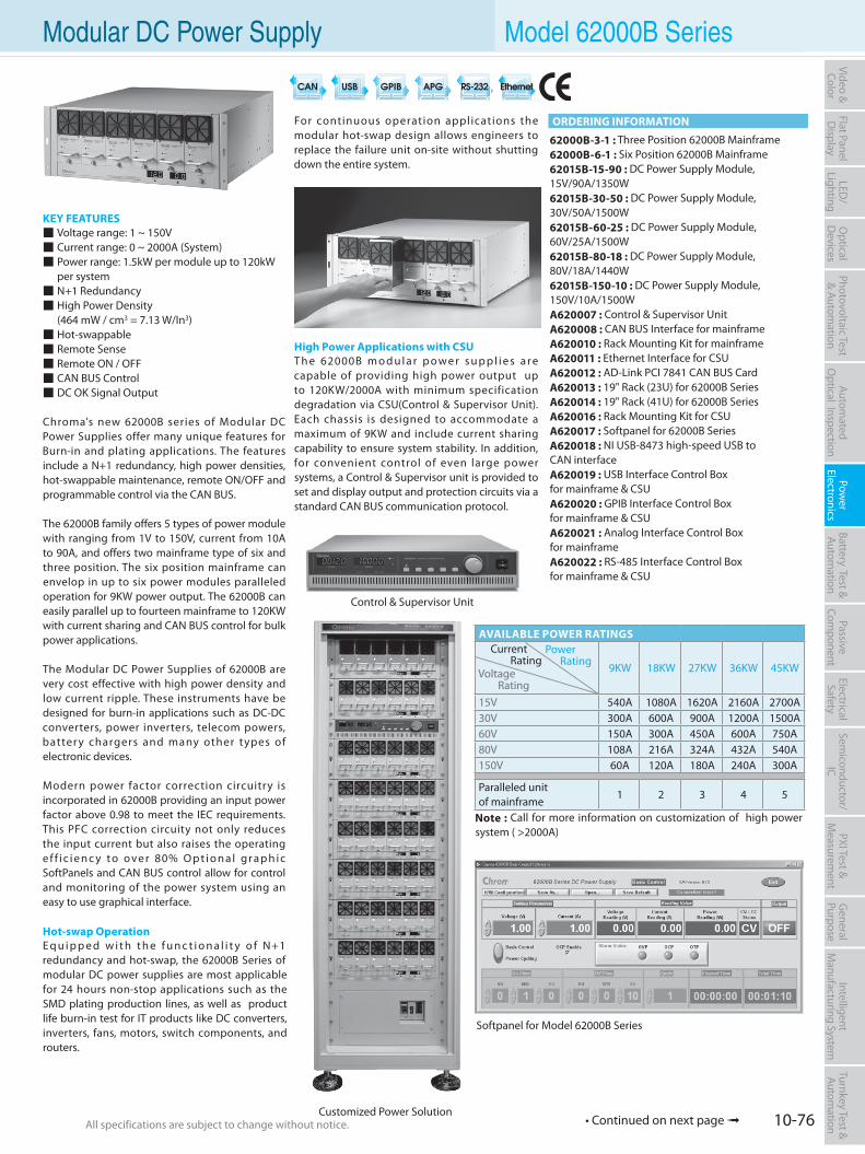
10-76All specifications are subject to change without notice. All specifications are subject to change without notice.
Flat PanelD
isplayPow
er Electronics
Electrical Safety
General
PurposePassive
Component
Semiconductor/
ICBattery Test & Autom
ationAutom
atedO
ptical Inspection Photovoltaic Test
& Automation
PXI Test &
Measurem
ent Video & Color
LED/
LightingO
ptical D
evicesIntelligent
Manufacturing System
Turnkey Test & Autom
ation Modular DC Power Supply Model 62000B Series
KEY FEATURES Voltage range: 1 ~ 150V Current range: 0 ~ 2000A (System) Power range: 1.5kW per module up to 120kW per system N+1 Redundancy High Power Density (464 mW / cm3 = 7.13 W/In3) Hot-swappable Remote Sense Remote ON / OFF CAN BUS Control DC OK Signal Output
Chroma's new 62000B series of Modular DC Power Supplies offer many unique features for Burn-in and plating applications. The features include a N+1 redundancy, high power densities, hot-swappable maintenance, remote ON/OFF and programmable control via the CAN BUS.
The 62000B family offers 5 types of power module with ranging from 1V to 150V, current from 10A to 90A, and offers two mainframe type of six and three position. The six position mainframe can envelop in up to six power modules paralleled operation for 9KW power output. The 62000B can easily parallel up to fourteen mainframe to 120KW with current sharing and CAN BUS control for bulk power applications.
The Modular DC Power Supplies of 62000B are very cost effective with high power density and low current ripple. These instruments have be designed for burn-in applications such as DC-DC converters, power inverters, telecom powers, batter y chargers and many other types of electronic devices.
Modern power factor correction circuitry is incorporated in 62000B providing an input power factor above 0.98 to meet the IEC requirements. This PFC correction circuity not only reduces the input current but also raises the operating e f f i c i e n c y t o o ve r 80% O p t i o n a l g r a p h i c SoftPanels and CAN BUS control allow for control and monitoring of the power system using an easy to use graphical interface.
Hot-swap OperationE q u i p p e d w i t h t h e f u n c t i o n a l i t y o f N+1 redundancy and hot-swap, the 62000B Series of modular DC power supplies are most applicable for 24 hours non-stop applications such as the SMD plating production lines, as well as product life burn-in test for IT products like DC converters, inverters, fans, motors, switch components, and routers.
For continuous operation applications the modular hot-swap design allows engineers to replace the failure unit on-site without shutting down the entire system.
High Power Applications with CSUT h e 62000B m o d u l a r p o w e r s u p p l i e s a r e capable of providing high power output up to 120KW/2000A with minimum specification degradation via CSU(Control & Supervisor Unit). Each chassis is designed to accommodate a maximum of 9KW and include current sharing capability to ensure system stability. In addition, for convenient control of even large power systems, a Control & Supervisor unit is provided to set and display output and protection circuits via a standard CAN BUS communication protocol.
AVAILABLE POWER RATINGS
9KW 18KW 27KW 36KW 45KW
15V 540A 1080A 1620A 2160A 2700A30V 300A 600A 900A 1200A 1500A60V 150A 300A 450A 600A 750A80V 108A 216A 324A 432A 540A150V 60A 120A 180A 240A 300A
Paralleled unit of mainframe
1 2 3 4 5
Note : Call for more information on customization of high power system ( >2000A)
Power Rating
Voltage Rating
Current Rating
Control & Supervisor Unit
62000B-3-1 : Three Position 62000B Mainframe62000B-6-1 : Six Position 62000B Mainframe62015B-15-90 : DC Power Supply Module, 15V/90A/1350W62015B-30-50 : DC Power Supply Module, 30V/50A/1500W62015B-60-25 : DC Power Supply Module, 60V/25A/1500W62015B-80-18 : DC Power Supply Module, 80V/18A/1440W62015B-150-10 : DC Power Supply Module, 150V/10A/1500WA620007 : Control & Supervisor UnitA620008 : CAN BUS Interface for mainframeA620010 : Rack Mounting Kit for mainframeA620011 : Ethernet Interface for CSUA620012 : AD-Link PCI 7841 CAN BUS CardA620013 : 19" Rack (23U) for 62000B SeriesA620014 : 19" Rack (41U) for 62000B SeriesA620016 : Rack Mounting Kit for CSUA620017 : Softpanel for 62000B SeriesA620018 : NI USB-8473 high-speed USB to CAN interfaceA620019 : USB Interface Control Box for mainframe & CSUA620020 : GPIB Interface Control Box for mainframe & CSUA620021 : Analog Interface Control Box for mainframeA620022 : RS-485 Interface Control Box for mainframe & CSU
Softpanel for Model 62000B Series
ORDERING INFORMATION
Customized Power Solution• Continued on next page
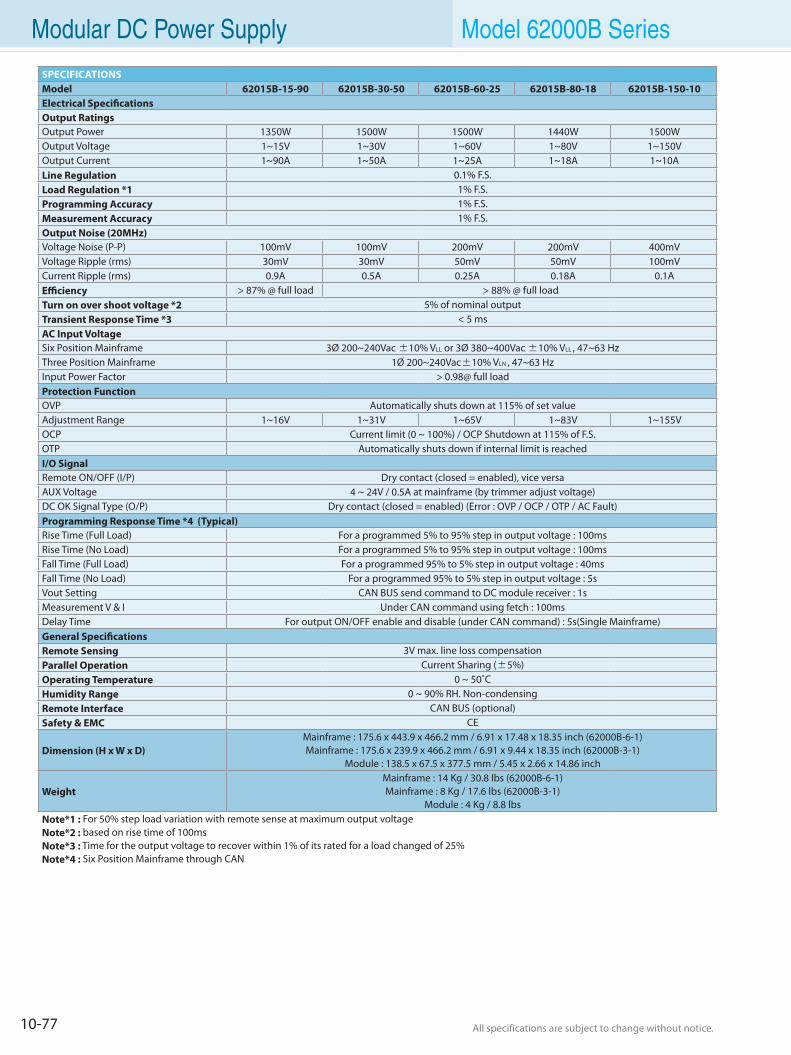
10-77 All specifications are subject to change without notice. All specifications are subject to change without notice.
Modular DC Power Supply Model 62000B Series
SPECIFICATIONSModel 62015B-15-90 62015B-30-50 62015B-60-25 62015B-80-18 62015B-150-10Electrical SpecificationsOutput RatingsOutput Power 1350W 1500W 1500W 1440W 1500WOutput Voltage 1~15V 1~30V 1~60V 1~80V 1~150VOutput Current 1~90A 1~50A 1~25A 1~18A 1~10ALine Regulation 0.1% F.S.Load Regulation *1 1% F.S.Programming Accuracy 1% F.S.Measurement Accuracy 1% F.S.Output Noise (20MHz)Voltage Noise (P-P) 100mV 100mV 200mV 200mV 400mVVoltage Ripple (rms) 30mV 30mV 50mV 50mV 100mVCurrent Ripple (rms) 0.9A 0.5A 0.25A 0.18A 0.1AEfficiency > 87% @ full load > 88% @ full loadTurn on over shoot voltage *2 5% of nominal outputTransient Response Time *3 < 5 msAC Input Voltage Six Position Mainframe 3Ø 200~240Vac ±10% VLL or 3Ø 380~400Vac ±10% VLL , 47~63 HzThree Position Mainframe 1Ø 200~240Vac±10% VLN , 47~63 HzInput Power Factor > 0.98@ full loadProtection FunctionOVP Automatically shuts down at 115% of set valueAdjustment Range 1~16V 1~31V 1~65V 1~83V 1~155VOCP Current limit (0 ~ 100%) / OCP Shutdown at 115% of F.S.OTP Automatically shuts down if internal limit is reachedI/O SignalRemote ON/OFF (I/P) Dry contact (closed = enabled), vice versaAUX Voltage 4 ~ 24V / 0.5A at mainframe (by trimmer adjust voltage)DC OK Signal Type (O/P) Dry contact (closed = enabled) (Error : OVP / OCP / OTP / AC Fault)Programming Response Time *4 (Typical)Rise Time (Full Load) For a programmed 5% to 95% step in output voltage : 100msRise Time (No Load) For a programmed 5% to 95% step in output voltage : 100msFall Time (Full Load) For a programmed 95% to 5% step in output voltage : 40msFall Time (No Load) For a programmed 95% to 5% step in output voltage : 5sVout Setting CAN BUS send command to DC module receiver : 1sMeasurement V & I Under CAN command using fetch : 100msDelay Time For output ON/OFF enable and disable (under CAN command) : 5s(Single Mainframe)General SpecificationsRemote Sensing 3V max. line loss compensationParallel Operation Current Sharing (±5%)Operating Temperature 0 ~ 50˚CHumidity Range 0 ~ 90% RH. Non-condensingRemote Interface CAN BUS (optional)Safety & EMC CE
Dimension (H x W x D)Mainframe : 175.6 x 443.9 x 466.2 mm / 6.91 x 17.48 x 18.35 inch (62000B-6-1)Mainframe : 175.6 x 239.9 x 466.2 mm / 6.91 x 9.44 x 18.35 inch (62000B-3-1)
Module : 138.5 x 67.5 x 377.5 mm / 5.45 x 2.66 x 14.86 inch
WeightMainframe : 14 Kg / 30.8 lbs (62000B-6-1)Mainframe : 8 Kg / 17.6 lbs (62000B-3-1)
Module : 4 Kg / 8.8 lbsNote*1 : For 50% step load variation with remote sense at maximum output voltageNote*2 : based on rise time of 100msNote*3 : Time for the output voltage to recover within 1% of its rated for a load changed of 25%Note*4 : Six Position Mainframe through CAN
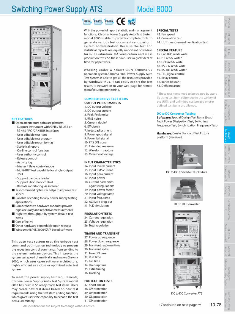
10-78All specifications are subject to change without notice. All specifications are subject to change without notice.
Flat PanelD
isplayPow
er Electronics
Electrical Safety
General
PurposePassive
Component
Semiconductor/
ICBattery Test & Autom
ationAutom
atedO
ptical Inspection Photovoltaic Test
& Automation
PXI Test &
Measurem
ent Video & Color
LED/
LightingO
ptical D
evicesIntelligent
Manufacturing System
Turnkey Test & Autom
ation Switching Power Supply ATS Model 8000
KEY FEATURES Open architecture software platform - Support instrument with GPIB / RS-232 or RS-485 / I2C /CAN BUS interfaces - User editable test item - User editable test program - User editable report format - Statistical report - On-line control function - User authority control - Release control - Activity log - Master / Slave control mode - Multi-UUT test capability for single-output
PSU - Support bar code reader - Support Shop-floor control - Remote monitoring via internet Test command optimizer helps to improve test
speed Capable of coding for any power supply testing
applications Comprehensive hardware modules provide
high accuracy and repetitive measurements High test throughput by system default test
items Cost effective Other hardware expandable upon request Windows 98/NT/2000/XP/7 based software
This auto test system uses the unique test command optimization technology to prevent the repeating control commands from sending to the system hardware devices. This improves the system test speed dramatically and makes Chroma 8000, which uses open software architecture, highly efficient as a close or optimized auto test system.
To meet the power supply test requirements, Chroma Power Supply Auto Test System model 8000 has built in 56 ready-made test items. Users may create new test items based on new test requirements using the test item editing function, which gives users the capability to expand the test items unlimitedly.
With the powerful report, statistic and management functions, Chroma Power Supply Auto Test System model 8000 is able to provide complete tools to generate various test documents and perform system administration. Because the test and statistical reports are equally important nowadays for R/D evaluation, QA verification and mass production tests. So these save users a great deal of time for paper work.
Wo r k i n g u n d e r Wi n d o w s 98/N T/2000/X P/7 operation system, Chroma 8000 Power Supply Auto Test System is able to get all the resources provided by Windows; thus, it can easily export the test results to network or to your web-page for remote manufacturing monitoring.
COMPREHENSIVE TEST ITEMSOUTPUT PERFORMANCES1. DC output voltage2. DC output current3. Peak-Peak noise4. RMS noise5. Current ripple*6. Efficiency7. In-test adjustment8. Power good signal9. Power fail signal10. P/ S ON signal11. Extended measure12. Waveform capture13. Overshoot voltage
INPUT CHARACTERISTICS14. Input Inrush current15. Input RMS current16. Input peak current17. Input power18. Current harmonics against regulations19. Input power factor20. Input voltage ramp21. Input freq. ramp22. AC cycle drop out23. PLD simulation
REGULATION TESTS24. Current regulation25. Voltage regulation26. Total regulation
TIMING AND TRANSIENT27. Power up sequence28. Power down sequence29. Transient response time30. Transient spike31. Turn ON time32. Rise time33. Fall time34. Hold-up time35. Extra timing36. Tracking
PROTECTION TESTS37. Short circuit38. OV protection39. UV protection40. OL protection41. OP protection
SPECIAL TESTS42. Fan speed43. Correlation test44. UUT measurement verification test
SPECIAL FEATURE45. Can BUS read/ write46. I2 C read/ write*47. GPIB read/ write48. RS-232 read/ write49. RS-485 read/ write*50. TTL signal control51. Relay control52. Bar code scan*53. DMM measure
* These test items need to be created by users by using test item editor due to the variety of the UUTs, and unlimited customized or user defined test items are allowed.
DC to DC Converter TestingSoftware: Special Design Test Items (Load Fault Power Dissipation Test, Switching Frequency Test, Synchnization Frequency Test)
Hardware: Create Standard Test Fixture platform (Receiver)
DC to DC Converter ATS
DC to DC Converter Test Fixture
DC to DC Converter
• Continued on next page
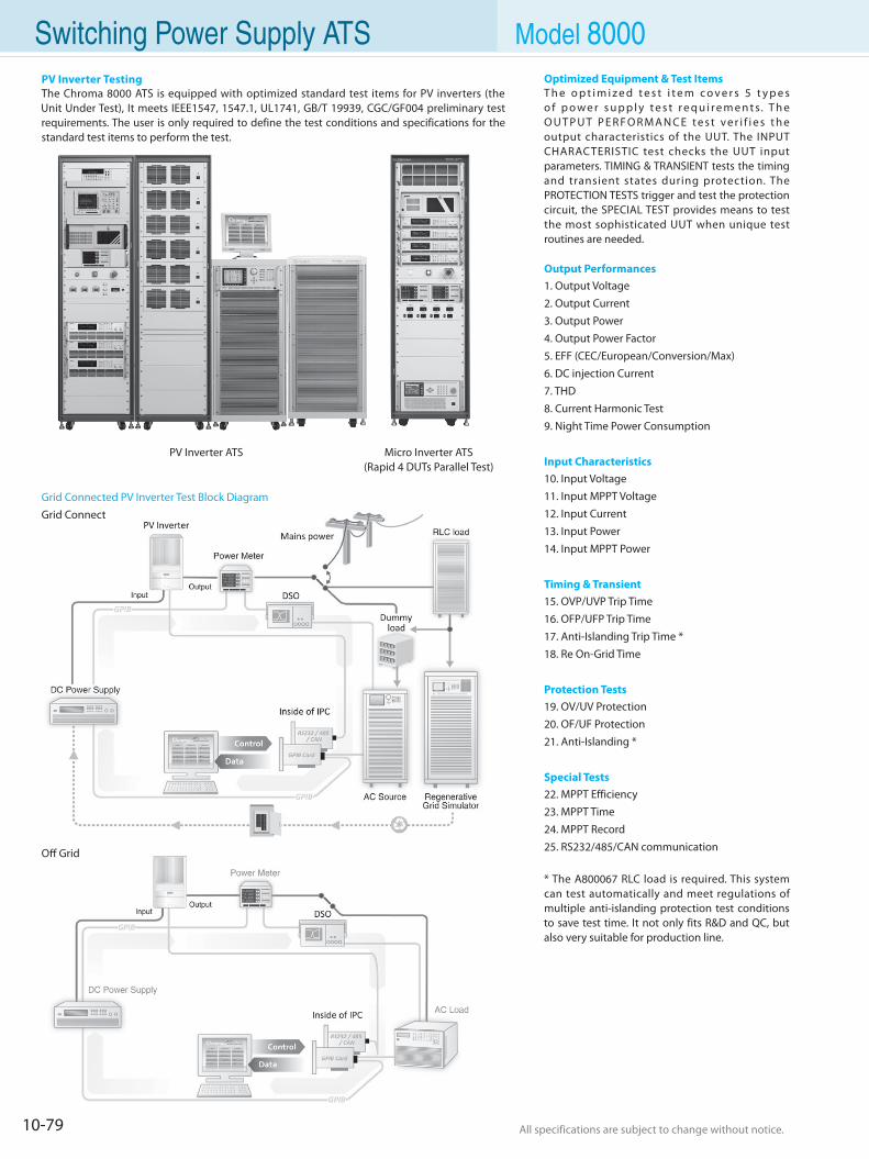
10-79 All specifications are subject to change without notice. All specifications are subject to change without notice.
Switching Power Supply ATS Model 8000
PV Inverter ATS Micro Inverter ATS(Rapid 4 DUTs Parallel Test)
Grid Connected PV Inverter Test Block DiagramGrid Connect
Off Grid
PV Inverter TestingThe Chroma 8000 ATS is equipped with optimized standard test items for PV inverters (the Unit Under Test), It meets IEEE1547, 1547.1, UL1741, GB/T 19939, CGC/GF004 preliminary test requirements. The user is only required to define the test conditions and specifications for the standard test items to perform the test.
Optimized Equipment & Test ItemsT h e o p t i m i z e d t e s t i t e m c o v e r s 5 t y p e s o f p o w e r s u p p l y t e s t r e q u i r e m e n t s. T h e O U T P U T P E R F O R M A N C E t e s t v e r i f i e s t h e output characteristics of the UUT. The INPUT CHARACTERISTIC test checks the UUT input parameters. TIMING & TRANSIENT tests the timing and transient states during protection. The PROTECTION TESTS trigger and test the protection circuit, the SPECIAL TEST provides means to test the most sophisticated UUT when unique test routines are needed.
Output Performances1. Output Voltage
2. Output Current
3. Output Power
4. Output Power Factor
5. EFF (CEC/European/Conversion/Max)
6. DC injection Current
7. THD
8. Current Harmonic Test
9. Night Time Power Consumption
Input Characteristics10. Input Voltage
11. Input MPPT Voltage
12. Input Current
13. Input Power
14. Input MPPT Power
Timing & Transient15. OVP/UVP Trip Time
16. OFP/UFP Trip Time
17. Anti-Islanding Trip Time *
18. Re On-Grid Time
Protection Tests19. OV/UV Protection
20. OF/UF Protection
21. Anti-Islanding *
Special Tests22. MPPT Efficiency
23. MPPT Time
24. MPPT Record
25. RS232/485/CAN communication
* The A800067 RLC load is required. This system can test automatically and meet regulations of multiple anti-islanding protection test conditions to save test time. It not only fits R&D and QC, but also very suitable for production line.
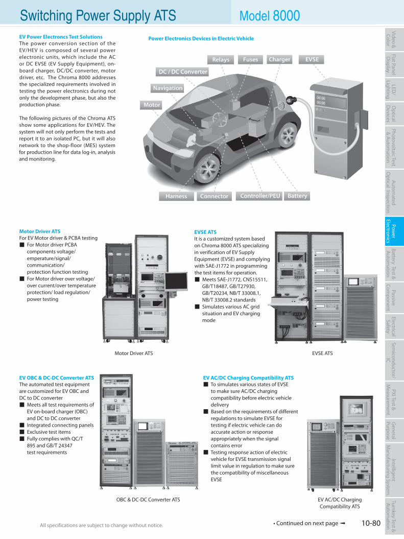
10-80All specifications are subject to change without notice. All specifications are subject to change without notice.
Flat PanelD
isplayPow
er Electronics
Electrical Safety
General
PurposePassive
Component
Semiconductor/
ICBattery Test & Autom
ationAutom
atedO
ptical Inspection Photovoltaic Test
& Automation
PXI Test &
Measurem
ent Video & Color
LED/
LightingO
ptical D
evicesIntelligent
Manufacturing System
Turnkey Test & Autom
ation Switching Power Supply ATS Model 8000EV Power Electroncs Test SolutionsThe power conversion section of the EV/HEV is composed of several power electronic units, which include the AC or DC EVSE (EV Supply Equipment), on-board charger, DC/DC converter, motor driver, etc. The Chroma 8000 addresses the specialized requirements involved in testing the power electronics during not only the development phase, but also the production phase.
The following pictures of the Chroma ATS show some applications for EV/HEV. The system will not only perform the tests and report it to an isolated PC, but it will also network to the shop-floor (MES) system for production line for data log-in, analysis and monitoring.
EVSE ATSIt is a customized system based on Chroma 8000 ATS specializing in verification of EV Supply Equipment (EVSE) and complying with SAE-J1772 in programming the test items for operation. Meets SAE-J1772, CNS15511, GB/T18487, GB/T27930, GB/T20234, NB/T 33008.1, NB/T 33008.2 standards Simulates various AC grid situation and EV charging mode
EV OBC & DC-DC Converter ATSThe automated test equipment are customized for EV OBC and DC to DC converter Meets all test requirements of EV on-board charger (OBC) and DC to DC converter Integrated connecting panels Exclusive test items Fully complies with QC/T 895 and GB/T 24347 test requirements
Motor Driver ATSFor EV Motor driver & PCBA testing For Motor driver PCBA components voltage/ emperature/signal/ communication/ protection function testing For Motor driver over voltage/ over current/over temperature protection/ load regulation/ power testing
EV AC/DC Charging Compatibility ATS To simulates various states of EVSE to make sure AC/DC charging compatibility before electric vehicle delivery Based on the requirements of different regulations to simulate EVSE for testing if electric vehicle can do accurate action or response appropriately when the signal contains error Testing response action of electric vehicle for EVSE transmission signal limit value in regulation to make sure the compatibility of miscellaneous EVSE
Power Electronics Devices in Electric Vehicle
OBC & DC-DC Converter ATS EV AC/DC ChargingCompatibility ATS
EVSE ATSMotor Driver ATS
• Continued on next page
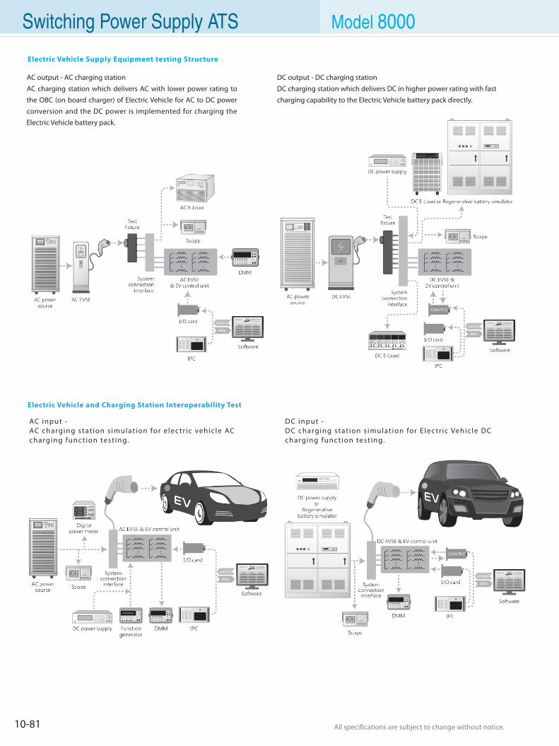
10-81 All specifications are subject to change without notice. All specifications are subject to change without notice.
Switching Power Supply ATS Model 8000
Electric Vehicle Supply Equipment testing Structure
AC output - AC charging stationAC charging station which delivers AC with lower power rating to the OBC (on board charger) of Electric Vehicle for AC to DC power conversion and the DC power is implemented for charging the Electric Vehicle battery pack.
DC output - DC charging stationDC charging station which delivers DC in higher power rating with fast charging capability to the Electric Vehicle battery pack directly.
AC input -AC charging stat ion s imulat ion for e lec tr ic vehic le AC charging func t ion test ing.
DC input -DC charging stat ion s imulat ion for E lec tr ic Vehic le DC charging func t ion test ing.
Electric Vehicle and Charging Station Interoperability Test
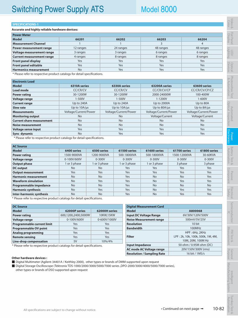
10-82All specifications are subject to change without notice. All specifications are subject to change without notice.
Flat PanelD
isplayPow
er Electronics
Electrical Safety
General
PurposePassive
Component
Semiconductor/
ICBattery Test & Autom
ationAutom
atedO
ptical Inspection Photovoltaic Test
& Automation
PXI Test &
Measurem
ent Video & Color
LED/
LightingO
ptical D
evicesIntelligent
Manufacturing System
Turnkey Test & Autom
ation Switching Power Supply ATS Model 8000
Accurate and highly reliable hardware devices:
SPECIFICATIONS-1
Digital Measurement CardModel A800068Input DC Voltage Range 6V/30V/120V/500VNoise Measurement range 500mV/5V/25VResolution 10 bitBandwidth 100MHz
FilterHPF : 6Hz, 2KHz
LPF : 2k, 10k, 100k, 500k, 1M, 4M, 10M, 20M, 100M Hz
Input Impedance 50 ohm / 0.95M ohm (DC)AC mode AC Voltage range 20V/150V/300V (rms)Resolution / Sampling Rate 16 bit / 1MS/s
Power MeterModel 66201 66202 66203 66204Measurement Channel 1 1 3 4Power measurement range 12 ranges 24 ranges 48 ranges 48 rangesVoltage measurement range 3 ranges 3 ranges 6 ranges 6 rangesCurrent measurement range 4 ranges 8 ranges 8 ranges 8 rangesFront panel display Yes Yes Yes YesFront panel editable Yes Yes Yes YesHarmonics measurement No Yes Yes Yes* Please refer to respective product catalogs for detail specifications.
Other hardware devices : Digital Multimeter (Agilent-34401A / Keithley 2000), other types or brands of DMM supported upon request Digital Storage Oscilloscope (Tektronix TDS-1000/2000/3000/5000/7000 series ,DPO-2000/3000/4000/5000/7000 series), other types or brands of DSO supported upon request
DC SourceModel 62000P series 62000H seriesPower rating 600,1200,2400,5000W 10KW,15KWVoltage range 0-100V/600V 0-600V/1000VProgrammable current limit Yes YesProgrammable OV point Yes YesAnalog programming Yes YesRemote sensing Yes YesLine-drop compensation 5V 10%/4%* Please refer to respective product catalogs for detail specifications.
AC SourceModel 6400 series 6500 series 61500 series 61600 series 61700 series 61800 seriesPower rating 1500-9000VA 1200-9000VA 500-18000VA 500-18000VA 1500-12000VA 30-60KVAVoltage range 0-100V/600V 0-300V 0-300V 0-300V 0-300V 0-300VOutput phase 1 or 3 phase 1 or 3 phase 1 or 3 phase 1 or 3 phase 3 phase 3 phaseDC output No No Yes Yes Yes YesOutput measurement Yes Yes Yes Yes Yes YesHarmonic measurement No No Yes No No YesWaveform simulation No Yes Yes No Yes YesProgrammable impedance No No Yes No No NoHarmonic synthesis No Yes Yes No Yes YesInter-harmonic synthesis No No Yes No Yes Yes* Please refer to respective product catalogs for detail specifications.
Electronic LoadModel 6310A series 6330A series 63200A series 63600 seriesLoad mode CC/CR/CV CC/CR/CV CC/CR/CV/CP CC/CR/CV/CP/CZPower rating 30-1200W 30-1200W 2000-24000W 100-400WVoltage range 1-500V 1-500V 1-1200V 1-600VCurrent range Up to 240A Up to 240A Up to 2000A Up to 80ASlew rate Up to 10A/µs Up to 10A/µs Up to 80A/µs Up to 8A/µsMeasurements Voltage/Current/Power Voltage/Current/Power Voltage/Current/Power Voltage/Current/PowerMonitoring output No No Voltage/Current Voltage/CurrentCurrent share measurement No No No NoNoise measurement No No No NoVoltage sense input Yes Yes Yes YesSync dynamic No Yes Yes Yes* Please refer to respective product catalogs for detail specifications.
• Continued on next page
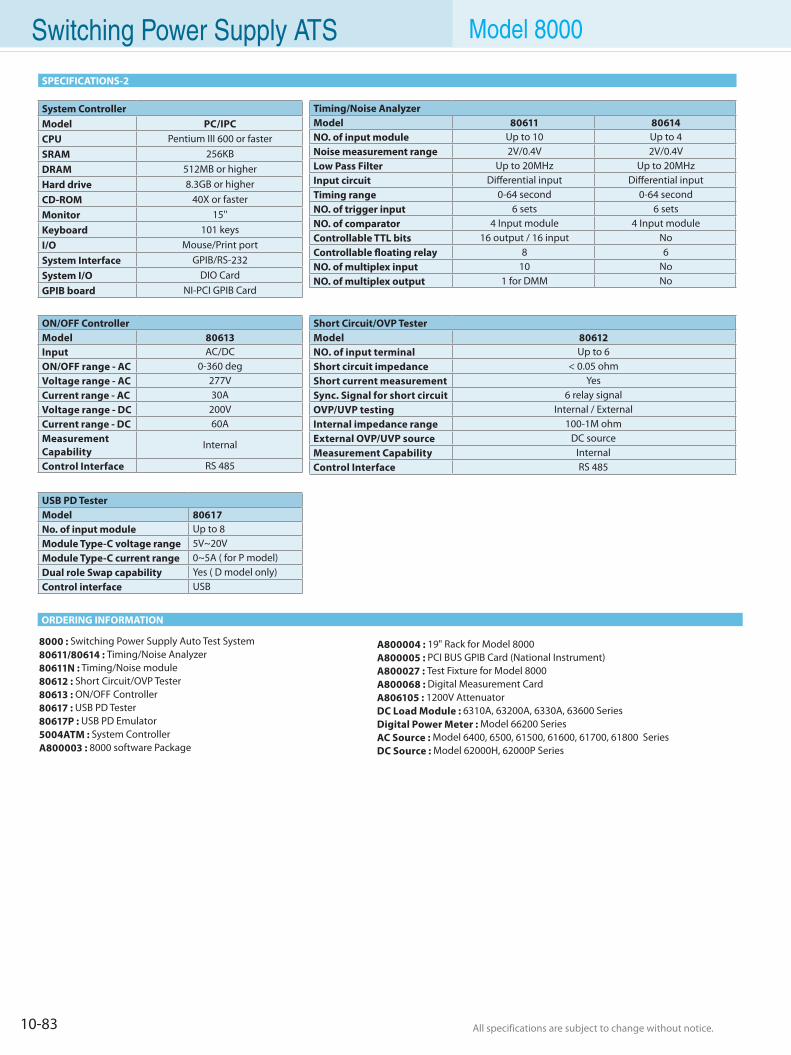
10-83 All specifications are subject to change without notice. All specifications are subject to change without notice.
SPECIFICATIONS-2
Switching Power Supply ATS Model 8000
ORDERING INFORMATION
System ControllerModel PC/IPCCPU Pentium III 600 or fasterSRAM 256KB DRAM 512MB or higherHard drive 8.3GB or higherCD-ROM 40X or fasterMonitor 15''Keyboard 101 keysI/O Mouse/Print portSystem Interface GPIB/RS-232System I/O DIO CardGPIB board NI-PCI GPIB Card
Timing/Noise AnalyzerModel 80611 80614NO. of input module Up to 10 Up to 4Noise measurement range 2V/0.4V 2V/0.4VLow Pass Filter Up to 20MHz Up to 20MHzInput circuit Differential input Differential inputTiming range 0-64 second 0-64 secondNO. of trigger input 6 sets 6 setsNO. of comparator 4 Input module 4 Input moduleControllable TTL bits 16 output / 16 input NoControllable floating relay 8 6NO. of multiplex input 10 NoNO. of multiplex output 1 for DMM No
Short Circuit/OVP TesterModel 80612NO. of input terminal Up to 6Short circuit impedance < 0.05 ohmShort current measurement YesSync. Signal for short circuit 6 relay signalOVP/UVP testing Internal / ExternalInternal impedance range 100-1M ohmExternal OVP/UVP source DC sourceMeasurement Capability InternalControl Interface RS 485
ON/OFF ControllerModel 80613Input AC/DCON/OFF range - AC 0-360 degVoltage range - AC 277VCurrent range - AC 30AVoltage range - DC 200VCurrent range - DC 60AMeasurementCapability
Internal
Control Interface RS 485
USB PD TesterModel 80617No. of input module Up to 8Module Type-C voltage range 5V~20VModule Type-C current range 0~5A ( for P model)Dual role Swap capability Yes ( D model only)Control interface USB
8000 : Switching Power Supply Auto Test System80611/80614 : Timing/Noise Analyzer80611N : Timing/Noise module80612 : Short Circuit/OVP Tester80613 : ON/OFF Controller80617 : USB PD Tester80617P : USB PD Emulator5004ATM : System ControllerA800003 : 8000 software Package
A800004 : 19" Rack for Model 8000A800005 : PCI BUS GPIB Card (National Instrument)A800027 : Test Fixture for Model 8000A800068 : Digital Measurement CardA806105 : 1200V AttenuatorDC Load Module : 6310A, 63200A, 6330A, 63600 SeriesDigital Power Meter : Model 66200 SeriesAC Source : Model 6400, 6500, 61500, 61600, 61700, 61800 SeriesDC Source : Model 62000H, 62000P Series
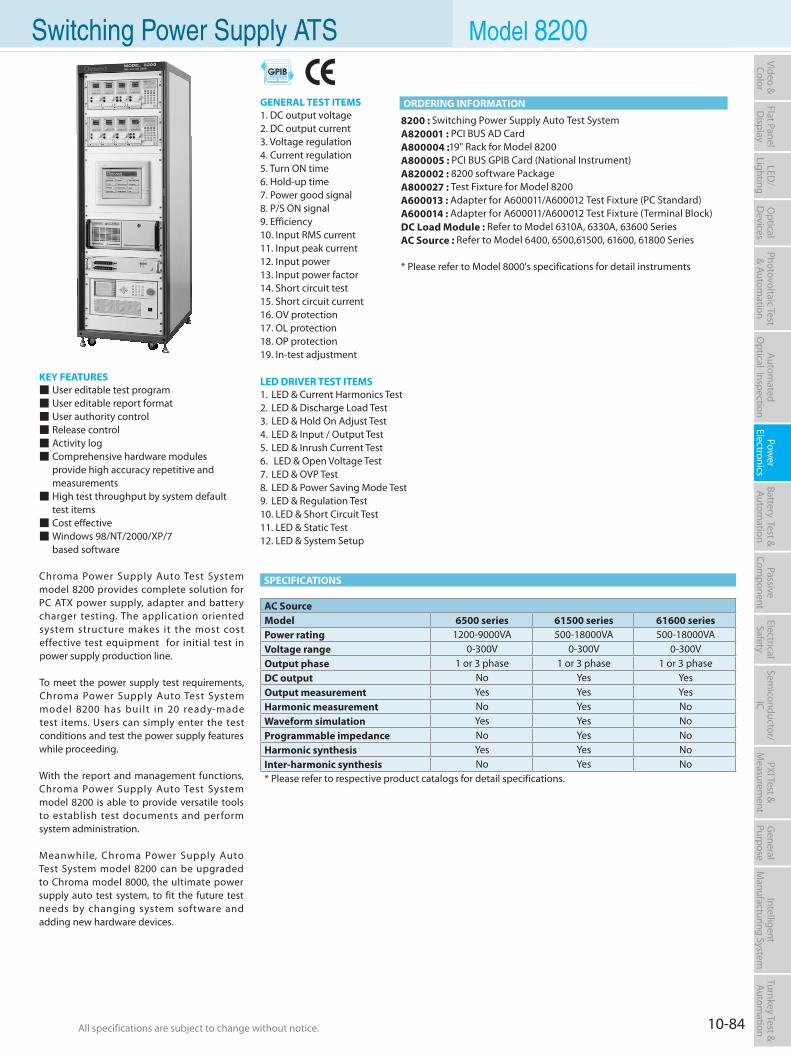
10-84All specifications are subject to change without notice. All specifications are subject to change without notice.
Flat PanelD
isplayPow
er Electronics
Electrical Safety
General
PurposePassive
Component
Semiconductor/
ICBattery Test & Autom
ationAutom
atedO
ptical Inspection Photovoltaic Test
& Automation
PXI Test &
Measurem
ent Video & Color
LED/
LightingO
ptical D
evicesIntelligent
Manufacturing System
Turnkey Test & Autom
ation Switching Power Supply ATS Model 8200
KEY FEATURES User editable test program User editable report format User authority control Release control Activity log Comprehensive hardware modules provide high accuracy repetitive and measurements High test throughput by system default test items Cost effective Windows 98/NT/2000/XP/7 based software
Chroma Power Supply Auto Test System model 8200 provides complete solution for PC ATX power supply, adapter and battery charger testing. The application oriented system structure makes it the most cost effective test equipment for initial test in power supply production line.
To meet the power supply test requirements, Chroma Power Supply Auto Test System model 8200 has built in 20 ready-made test items. Users can simply enter the test conditions and test the power supply features while proceeding.
With the report and management functions, Chroma Power Supply Auto Test System model 8200 is able to provide versatile tools to establish test documents and perform system administration.
Meanwhile, Chroma Power Supply Auto Test System model 8200 can be upgraded to Chroma model 8000, the ultimate power supply auto test system, to fit the future test needs by changing system software and adding new hardware devices.
8200 : Switching Power Supply Auto Test SystemA820001 : PCI BUS AD Card A800004 :19" Rack for Model 8200A800005 : PCI BUS GPIB Card (National Instrument)A820002 : 8200 software PackageA800027 : Test Fixture for Model 8200A600013 : Adapter for A600011/A600012 Test Fixture (PC Standard)A600014 : Adapter for A600011/A600012 Test Fixture (Terminal Block)DC Load Module : Refer to Model 6310A, 6330A, 63600 SeriesAC Source : Refer to Model 6400, 6500,61500, 61600, 61800 Series
* Please refer to Model 8000's specifications for detail instruments
SPECIFICATIONS
AC SourceModel 6500 series 61500 series 61600 seriesPower rating 1200-9000VA 500-18000VA 500-18000VAVoltage range 0-300V 0-300V 0-300VOutput phase 1 or 3 phase 1 or 3 phase 1 or 3 phaseDC output No Yes YesOutput measurement Yes Yes YesHarmonic measurement No Yes NoWaveform simulation Yes Yes NoProgrammable impedance No Yes NoHarmonic synthesis Yes Yes NoInter-harmonic synthesis No Yes No* Please refer to respective product catalogs for detail specifications.
ORDERING INFORMATIONGENERAL TEST ITEMS1. DC output voltage2. DC output current3. Voltage regulation4. Current regulation 5. Turn ON time6. Hold-up time7. Power good signal8. P/S ON signal9. Efficiency10. Input RMS current11. Input peak current12. Input power13. Input power factor14. Short circuit test15. Short circuit current16. OV protection17. OL protection18. OP protection19. In-test adjustment
LED DRIVER TEST ITEMS1. LED & Current Harmonics Test 2. LED & Discharge Load Test3. LED & Hold On Adjust Test4. LED & Input / Output Test5. LED & Inrush Current Test 6. LED & Open Voltage Test7. LED & OVP Test8. LED & Power Saving Mode Test9. LED & Regulation Test10. LED & Short Circuit Test11. LED & Static Test12. LED & System Setup
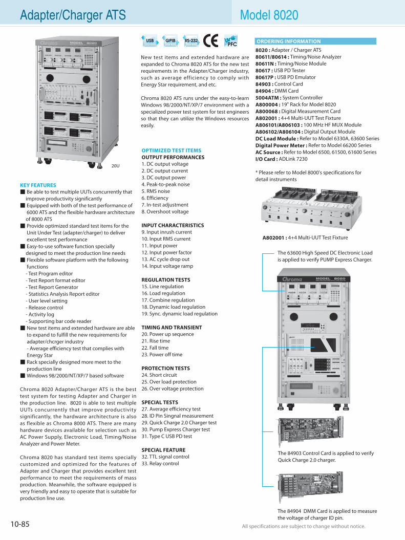
10-85 All specifications are subject to change without notice. All specifications are subject to change without notice.
Adapter/Charger ATS Model 8020
KEY FEATURES Be able to test multiple UUTs concurrently that improve productivity significantly Equipped with both of the test performance of 6000 ATS and the flexible hardware architecture of 8000 ATS Provide optimized standard test items for the Unit Under Test (adapter/charger) to deliver excellent test performance Easy-to-use software function specially designed to meet the production line needs Flexible software platform with the following functions - Test Program editor - Test Report format editor - Test Report Generator - Statistics Analysis Report editor - User level setting - Release control - Activity log - Supporting bar code reader New test items and extended hardware are able to expand to fulfill the new requirements for adapter/chcrger industry - Average efficiency test that complies with Energy Star Rack specially designed more meet to the production line Windows 98/2000/NT/XP/7 based software
Chroma 8020 Adapter/Charger ATS is the best test system for testing Adapter and Charger in the production line. 8020 is able to test multiple UUTs concurrently that improve productivity significantly, the hardware architecture is also as flexible as Chroma 8000 ATS. There are many hardware devices available for selection such as AC Power Supply, Electronic Load, Timing/Noise Analyzer and Power Meter.
Chroma 8020 has standard test items specially customized and optimized for the features of Adapter and Charger that provides excellent test performance to meet the requirements of mass production. Meanwhile, the software equipped is very friendly and easy to operate that is suitable for production line use.
8020 : Adapter / Charger ATS80611/80614 : Timing/Noise Analyzer80611N : Timing/Noise Module80617 : USB PD Tester80617P : USB PD Emulator84903 : Control Card84904 : DMM Card5004ATM : System ControllerA800004 : 19" Rack for Model 8020A800068 : Digital Measurement CardA802001 : 4+4 Multi-UUT Test FixtureA806101/A806103 : 100 MHz HF MUX ModuleA806102/A806104 : Digital Output ModuleDC Load Module : Refer to Model 6330A, 63600 SeriesDigital Power Meter : Refer to Model 66200 SeriesAC Source : Refer to Model 6500, 61500, 61600 SeriesI/O Card : ADLink 7230
* Please refer to Model 8000's specifications fordetail instruments
OPTIMIZED TEST ITEMSOUTPUT PERFORMANCES1. DC output voltage2. DC output current3. DC output power4. Peak-to-peak noise5. RMS noise6. Efficiency7. In-test adjustment8. Overshoot voltage
INPUT CHARACTERISTICS9. Input inrush current10. Input RMS current11. Input power12. Input power factor13. AC cycle drop out14. Input voltage ramp
REGULATION TESTS15. Line regulation16. Load regulation17. Combine regulation18. Dynamic load regulation19. Sync. dynamic load regulation
TIMING AND TRANSIENT20. Power up sequence21. Rise time22. Fall time23. Power off time
PROTECTION TESTS24. Short circuit25. Over load protection26. Over voltage protection
SPECIAL TESTS27. Average efficiency test28. ID Pin Singnal measurement29. Quick Charge 2.0 Charger test30. Pump Express Charger test31. Type C USB PD test
SPECIAL FEATURE32. TTL signal control33. Relay control
ORDERING INFORMATION
20U
New test items and extended hardware are expanded to Chroma 8020 ATS for the new test requirements in the Adapter/Charger industry, such as average efficiency to comply with Energy Star requirement, and etc.
Chroma 8020 ATS runs under the easy-to-learn Windows 98/2000/NT/XP/7 environment with a specialized power test system for test engineers so that they can utilize the Windows resources easily.
A802001 : 4+4 Multi-UUT Test Fixture
The 84903 Control Card is applied to verify Quick Charge 2.0 charger.
The 84904 DMM Card is applied to measure the voltage of charger ID pin.
The 63600 High Speed DC Electronic Loadis applied to verify PUMP Express Charger.
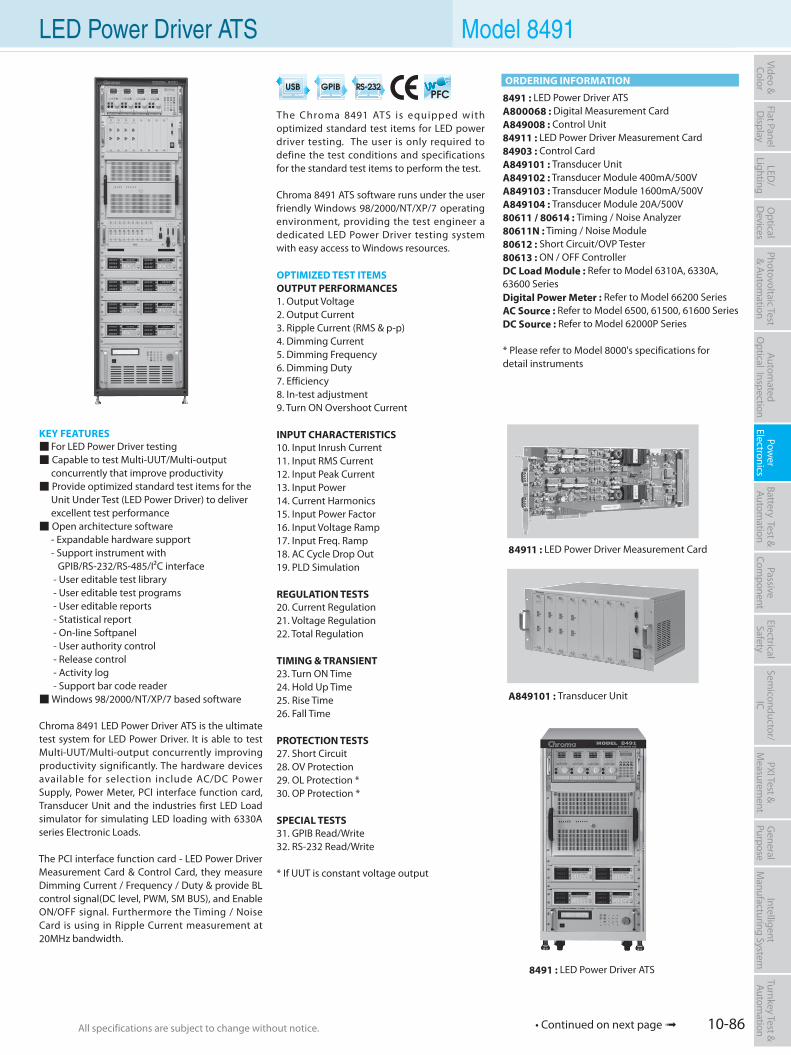
10-86All specifications are subject to change without notice. All specifications are subject to change without notice.
Flat PanelD
isplayPow
er Electronics
Electrical Safety
General
PurposePassive
Component
Semiconductor/
ICBattery Test & Autom
ationAutom
atedO
ptical Inspection Photovoltaic Test
& Automation
PXI Test &
Measurem
ent Video & Color
LED/
LightingO
ptical D
evicesIntelligent
Manufacturing System
Turnkey Test & Autom
ation LED Power Driver ATS Model 8491
KEY FEATURES For LED Power Driver testing Capable to test Multi-UUT/Multi-output concurrently that improve productivity Provide optimized standard test items for the Unit Under Test (LED Power Driver) to deliver excellent test performance Open architecture software - Expandable hardware support - Support instrument with GPIB/RS-232/RS-485/I²C interface - User editable test library - User editable test programs - User editable reports - Statistical report - On-line Softpanel - User authority control - Release control - Activity log - Support bar code reader Windows 98/2000/NT/XP/7 based software
Chroma 8491 LED Power Driver ATS is the ultimate test system for LED Power Driver. It is able to test Multi-UUT/Multi-output concurrently improving productivity significantly. The hardware devices available for selection include AC/DC Power Supply, Power Meter, PCI interface function card, Transducer Unit and the industries first LED Load simulator for simulating LED loading with 6330A series Electronic Loads.
The PCI interface function card - LED Power Driver Measurement Card & Control Card, they measure Dimming Current / Frequency / Duty & provide BL control signal(DC level, PWM, SM BUS), and Enable ON/OFF signal. Furthermore the Timing / Noise Card is using in Ripple Current measurement at 20MHz bandwidth.
The Chroma 8491 ATS is equipped with optimized standard test items for LED power driver testing. The user is only required to define the test conditions and specifications for the standard test items to perform the test.
Chroma 8491 ATS software runs under the user friendly Windows 98/2000/NT/XP/7 operating environment, providing the test engineer a dedicated LED Power Driver testing system with easy access to Windows resources.
OPTIMIZED TEST ITEMSOUTPUT PERFORMANCES1. Output Voltage2. Output Current3. Ripple Current (RMS & p-p)4. Dimming Current5. Dimming Frequency6. Dimming Duty7. Efficiency8. In-test adjustment9. Turn ON Overshoot Current
INPUT CHARACTERISTICS10. Input Inrush Current11. Input RMS Current12. Input Peak Current13. Input Power14. Current Harmonics15. Input Power Factor16. Input Voltage Ramp17. Input Freq. Ramp18. AC Cycle Drop Out19. PLD Simulation
REGULATION TESTS20. Current Regulation 21. Voltage Regulation 22. Total Regulation
TIMING & TRANSIENT23. Turn ON Time 24. Hold Up Time25. Rise Time26. Fall Time
PROTECTION TESTS27. Short Circuit28. OV Protection29. OL Protection *30. OP Protection *
SPECIAL TESTS31. GPIB Read/Write32. RS-232 Read/Write
* If UUT is constant voltage output
84911 : LED Power Driver Measurement Card
A849101 : Transducer Unit
8491 : LED Power Driver ATSA800068 : Digital Measurement CardA849008 : Control Unit84911 : LED Power Driver Measurement Card84903 : Control CardA849101 : Transducer UnitA849102 : Transducer Module 400mA/500VA849103 : Transducer Module 1600mA/500VA849104 : Transducer Module 20A/500V80611 / 80614 : Timing / Noise Analyzer80611N : Timing / Noise Module80612 : Short Circuit/OVP Tester80613 : ON / OFF ControllerDC Load Module : Refer to Model 6310A, 6330A, 63600 SeriesDigital Power Meter : Refer to Model 66200 SeriesAC Source : Refer to Model 6500, 61500, 61600 SeriesDC Source : Refer to Model 62000P Series
* Please refer to Model 8000's specifications fordetail instruments
ORDERING INFORMATION
8491 : LED Power Driver ATS
• Continued on next page
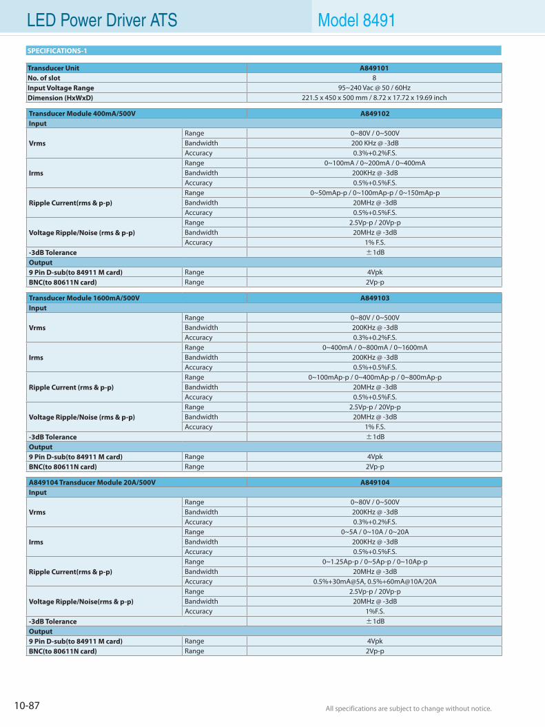
10-87 All specifications are subject to change without notice. All specifications are subject to change without notice.
LED Power Driver ATS Model 8491
SPECIFICATIONS-1
Transducer Unit A849101No. of slot 8Input Voltage Range 95~240 Vac @ 50 / 60HzDimension (HxWxD) 221.5 x 450 x 500 mm / 8.72 x 17.72 x 19.69 inch
Transducer Module 400mA/500V A849102Input
VrmsRange 0~80V / 0~500VBandwidth 200 KHz @ -3dBAccuracy 0.3%+0.2%F.S.
IrmsRange 0~100mA / 0~200mA / 0~400mABandwidth 200KHz @ -3dBAccuracy 0.5%+0.5%F.S.
Ripple Current(rms & p-p)Range 0~50mAp-p / 0~100mAp-p / 0~150mAp-pBandwidth 20MHz @ -3dBAccuracy 0.5%+0.5%F.S.
Voltage Ripple/Noise (rms & p-p)Range 2.5Vp-p / 20Vp-pBandwidth 20MHz @ -3dBAccuracy 1% F.S.
-3dB Tolerance ±1dBOutput9 Pin D-sub(to 84911 M card) Range 4VpkBNC(to 80611N card) Range 2Vp-p
Transducer Module 1600mA/500V A849103Input
VrmsRange 0~80V / 0~500VBandwidth 200KHz @ -3dBAccuracy 0.3%+0.2%F.S.
IrmsRange 0~400mA / 0~800mA / 0~1600mABandwidth 200KHz @ -3dBAccuracy 0.5%+0.5%F.S.
Ripple Current (rms & p-p)Range 0~100mAp-p / 0~400mAp-p / 0~800mAp-pBandwidth 20MHz @ -3dBAccuracy 0.5%+0.5%F.S.
Voltage Ripple/Noise (rms & p-p)Range 2.5Vp-p / 20Vp-pBandwidth 20MHz @ -3dBAccuracy 1% F.S.
-3dB Tolerance ±1dBOutput9 Pin D-sub(to 84911 M card) Range 4VpkBNC(to 80611N card) Range 2Vp-p
A849104 Transducer Module 20A/500V A849104Input
VrmsRange 0~80V / 0~500VBandwidth 200KHz @ -3dBAccuracy 0.3%+0.2%F.S.
IrmsRange 0~5A / 0~10A / 0~20ABandwidth 200KHz @ -3dBAccuracy 0.5%+0.5%F.S.
Ripple Current(rms & p-p)Range 0~1.25Ap-p / 0~5Ap-p / 0~10Ap-pBandwidth 20MHz @ -3dBAccuracy 0.5%+30mA@5A, 0.5%+60mA@10A/20A
Voltage Ripple/Noise(rms & p-p)Range 2.5Vp-p / 20Vp-pBandwidth 20MHz @ -3dBAccuracy 1%F.S.
-3dB Tolerance ±1dBOutput9 Pin D-sub(to 84911 M card) Range 4VpkBNC(to 80611N card) Range 2Vp-p
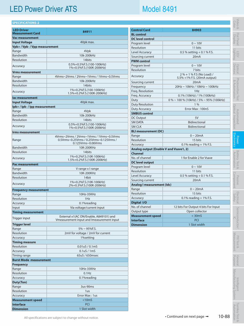
10-88All specifications are subject to change without notice. All specifications are subject to change without notice.
Flat PanelD
isplayPow
er Electronics
Electrical Safety
General
PurposePassive
Component
Semiconductor/
ICBattery Test & Autom
ationAutom
atedO
ptical Inspection Photovoltaic Test
& Automation
PXI Test &
Measurem
ent Video & Color
LED/
LightingO
ptical D
evicesIntelligent
Manufacturing System
Turnkey Test & Autom
ation LED Power Driver ATS Model 8491
SPECIFICATIONS-2
LED Driver Measurement Card 84911
Vac measurementInput Voltage 4Vpk max.Vpk+ / Vpk- / Vpp measurementRange 4VpkBandwidth 10k-200kHzResolution 14bits
Accuracy 0.5%+0.5%F.S.(100-100kHz) 1%+0.5%F.S.(100K-200kHz)
Vrms measurementRange 4Vrms~2Vrms / 2Vrms~1Vrms / 1Vrms~0.5VrmsBandwidth 10k-200kHzResolution 14bits
Accuracy 1%+0.2%F.S.(100-100kHz) 1.5%+0.2%F.S.(100K-200kHz)
Iac measurementInput Voltage 4Vpk max.Ipk+ / Ipk- / Ipp measurementRange 4VpkBandwidth 10k-200kHzResolution 14bits
Accuracy 0.5%+0.5%F.S.(100-100kHz)1%+0.5%F.S.(100K-200kHz)
Irms measurement
Range4Vrms~2Vrms / 2Vrms~1Vrms / 1Vrms~0.5Vrms
0.5Vrms~0.25Vrms / 0.25Vrms~0.125Vrms / 0.125Vrms~0.06Vrms
Bandwidth 10K-200KHzResolution 14bits
Accuracy 1%+0.2%F.S.(10K-100kHz) 1.5%+0.2%F.S.(100K-200kHz)
Pac measurementRange V range x I rangeBandwidth 10K-200KHzResolution 14bit
Accuracy 1%+0.2%F.S.(10K-100kHz) 2%+0.3%F.S.(100K-200kHz)
Frequency measurementRange 10Hz-35KHzResolution 1HzAccuracy 0.1%readingInput Via voltage/current inputTiming measurement
Trigger input External x1(AC ON/Enable, A849101) and Vmeasurement input and Imeasurement input
Trigger levelRange 5% ~ 95%F.S.Resolution 2mV for voltage / 2mV for currentAccuracy 1%settingTiming measureResolution 0.01uS / 0.1mSAccuracy 0.1uS / 1mSTiming range 65uS / 650msecBurst Mode measurementFrequencyRange 10Hz-35KHzResolution 0.1HzAccuracy 0.1%readingDuty(Ton)Range 3us-90msResolution 1usAccuracy Error Max : 1usMeasurement speed <10mSInterface PCIDimension 1 Slot width
Control Card 84903BL controlDC level controlProgram level 0 ~ 10VResolution 11 bitsLevel Accuracy 0.5 % setting + 0.1 % F.S.Sourcing current 20mAPWM controlProgram level 0 ~ 10VResolution 7 bits
Accuracy 2 % + 1 % F.S (No Load) / 5.5% +1% F.S. (20mA output)
Sourcing current 20mAFrequency 20Hz ~ 10kHz / 10kHz ~ 100kHzFreq. Resolution 1HzFreq. Accuracy 0.1% (10kHz) / 1% (100kHz)Duty 0 % ~ 100 % (10kHz) / 5% ~ 95% (100kHz)Duty Resolution 1 %Duty Accuracy Error Max : 100nSSMBUS controlDC Output 5VSM DATA BidirectionalSM CLK BidirectionalBLI measurement (DC)Range 0 ~ 20mAResolution 15 bitsAccuracy 0.1% reading + 1% F.S.Analog output (Enable V and Vsave1, 2)ChannelNo. of channel 1 for Enable 2 for VsaveDC level outputProgram level 0 ~ 10VResolution 11 bitsLevel Accuracy 0.5 % setting + 0.1 % F.S.Sourcing current 20mAAnalog I measurement (Idc)Range 0 ~ 20mAResolution 15 bitsAccuracy 0.1% reading + 1% F.S.Digital I/ONo. of channel 12 bits For Output 4 bits For InputOutput type Open collectorMeasurement speed < 30mSInterface PCIDimension 1 Slot width
• Continued on next page

Battery Test & Automation Solution
Battery Cell Test and Formation System 11-1
Battery Cell Charge & Discharge Test System 11-3
Regenerative Battery Pack Test System 11-5
Battery Pack ATS 11-17
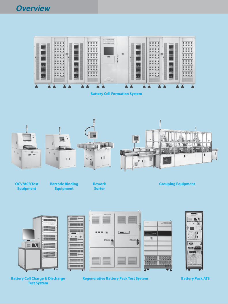
Overview
Regenerative Battery Pack Test System Battery Pack ATS
Grouping Equipment
Battery Cell Formation System
OCV/ACR TestEquipment
ReworkSorter
Battery Cell Charge & Discharge Test System
Barcode BindingEquipment
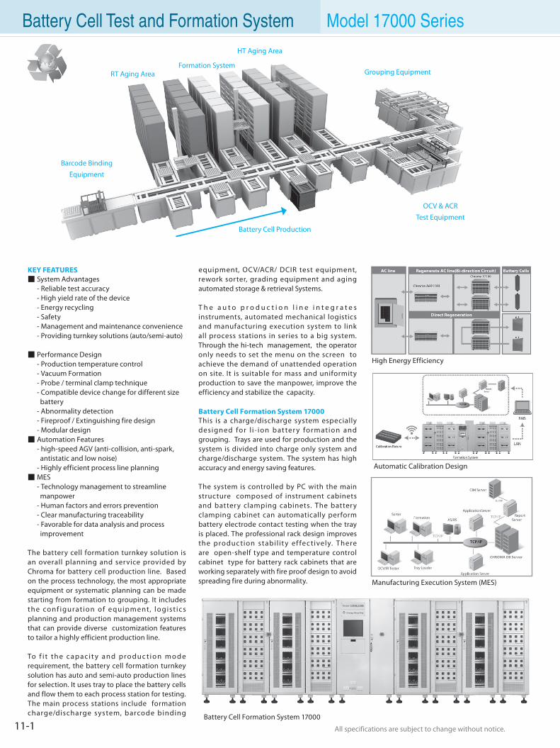
All specifications are subject to change without notice. All specifications are subject to change without notice.11-1
Battery Cell Test and Formation System Model 17000 Series
Barcode BindingEquipment
RT Aging AreaFormation System
HT Aging Area
OCV & ACRTest Equipment
Grouping Equipment
Battery Cell Production
KEY FEATURES System Advantages - Reliable test accuracy - High yield rate of the device - Energy recycling - Safety - Management and maintenance convenience - Providing turnkey solutions (auto/semi-auto)
Performance Design - Production temperature control - Vacuum Formation - Probe / terminal clamp technique - Compatible device change for different size battery - Abnormality detection - Fireproof / Extinguishing fire design - Modular design Automation Features - high-speed AGV (anti-collision, anti-spark, antistatic and low noise) - Highly efficient process line planning MES - Technology management to streamline manpower - Human factors and errors prevention - Clear manufacturing traceability - Favorable for data analysis and process improvement
The battery cell formation turnkey solution is an overall planning and service provided by Chroma for battery cell production line. Based on the process technology, the most appropriate equipment or systematic planning can be made starting from formation to grouping. It includes the conf igurat ion of e quipment, logist ic s planning and production management systems that can provide diverse customization features to tailor a highly efficient production line.
To f i t th e c ap a ci t y an d p ro du c t i o n m o d e requirement, the battery cell formation turnkey solution has auto and semi-auto production lines for selection. It uses tray to place the battery cells and flow them to each process station for testing. The main process stations include formation charge/discharge system, barcode binding
equipment, OCV/ACR/ DCIR test equipment, rework sorter, grading equipment and aging automated storage & retrieval Systems.
T h e a u t o p r o d u c t i o n l i n e i n t e g r a t e s instruments, automated mechanical logistics and manufacturing execution system to link all process stations in series to a big system. Through the hi-tech management, the operator only needs to set the menu on the screen to achieve the demand of unattended operation on site. It is suitable for mass and uniformity production to save the manpower, improve the efficiency and stabilize the capacity.
Battery Cell Formation System 17000This is a charge/discharge system especially designed for l i - ion bat ter y formation and grouping. Trays are used for production and the system is divided into charge only system and charge/discharge system. The system has high accuracy and energy saving features.
The system is controlled by PC with the main structure composed of instrument cabinets and battery clamping cabinets. The battery clamping cabinet can automatically perform battery electrode contact testing when the tray is placed. The professional rack design improves the produc tion stabil it y ef fec tively. There are open-shelf type and temperature control cabinet type for battery rack cabinets that are working separately with fire proof design to avoid spreading fire during abnormality.
High Energy Efficiency
Battery Cell Formation System 17000
Automatic Calibration Design
Manufacturing Execution System (MES)
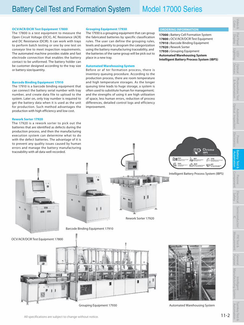
All specifications are subject to change without notice. All specifications are subject to change without notice. 11-2
Flat PanelD
isplayPow
er Electronics
Electrical Safety
General
PurposePassive
Component
Semiconductor/
ICBattery Test & Autom
ationAutom
atedO
ptical Inspection Photovoltaic Test
& Automation
PXI Test &
Measurem
ent Video & Color
LED/
LightingO
ptical D
evicesIntelligent
Manufacturing System
Turnkey Test & Autom
ation Battery Cell Test and Formation System Model 17000 Series
Barcode Binding Equipment 17910
OCV/ACR/DCIR Test Equipment 17800The 17800 is a test equipment to measure the Open Circuit Voltage (OCV), AC Resistance (ACR) and DC Resistance (DCIR). It can work with trays to perform batch testing or one by one test on conveyor line to meet inspection requirements. The automated machine provides stable and fast electrode connection that enables the battery contact to be uniformed. The battery holder can be customer designed according to the tray size or battery size/quantity.
Barcode Binding Equipment 17910The 17910 is a barcode binding equipment that can connect the battery serial number with tray number, and create data file to upload to the system. Later on, only tray number is required to get the battery data when it is used as the unit for production. Such method advantages the production with high efficiency and low cost.
Rework Sorter 17920The 17920 is a rework sorter to pick out the batteries that are identified as defects during the production process, and then the manufacturing execution system can determine what to do with the defect batteries. The advantage of it is to prevent any quality issues caused by human errors and manage the battery manufacturing traceability with all data well recorded.
Grouping Equipment 17930The 17930 is a grouping equipment that can group the fabricated batteries by specific classification rules. The user can define the grouping rules, levels and quantity to program the categorization using the battery manufacturing traceability, andthe batteries of the same group will be pick out toplace in a new tray.
Automated Warehousing SystemBefore or af ter formation process, there is inventory queuing procedure. According to the production process, there are room temperature and high temperature storages. As the longer queuing time leads to huge storage, a system is often used to substitute human for management;and the strengths of using it are high utilization of space, less human errors, reduction of process differences, detailed control logs and efficiency improvement.
17000 : Battery Cell Formation System17800 : OCV/ACR/DCIR Test Equipment17910 : Barcode Binding Equipment17920 : Rework Sorter17930 : Grouping Equipment Automated Warehousing SystemIntelligent Battery Process System (IBPS)
ORDERING INFORMATION
Automated Warehousing SystemGrouping Equipment 17930
Rework Sorter 17920
Intelligent Battery Process System (IBPS)
OCV/ACR/DCIR Test Equipment 17800
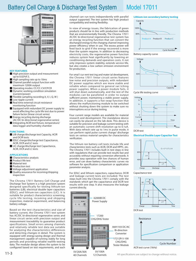
All specifications are subject to change without notice. All specifications are subject to change without notice.11-3
KEY FEATURES High precision output and measurement up to 0.02%F.S. High sampling rate up to 10ms Channel parallel output function with maximum 1200A output Operating modes: CC/CC-CV/CP/CR Dynamic working condition simulation (current/power) Flexible sampling recording (t, V, I, Q, W ) Low ripple current Real time external circuit resistance monitoring function Equipped with redundant DC power supply to avoid affecting the cycle life test due to power failure factor (linear circuit series) Energy recycling during discharge (AC/DC bi-directional regenerative series) Integrating ACIR test fixture, temperature/ data logger and humidity chamber
FUNCTIONS LIB charge/discharge test Capacity, ACIR and DCIR tests EDLC charge/discharge test Capacitance, ACIR, DCR and LC tests LIC charge/discharge test Capacitance, ACIR, DCR and LC tests APPLICATIONS Characteristics analysis Product life test Material test Production test Voltage adjustment application Quality assurance for incoming/shipping inspection
The Chroma 17011 Battery Cell Charge and Discharge Test System is a high precision system designed specifically for testing lithium-ion batteries (LIB), electrical double layer capacitors (EDLC), and lithium-ion capacitors (LIC). It is suitable for product characteristics screening, c yc le l i fe test ing, incoming and shipping inspection, material experiment, and balancing battery voltage.
Based on the test characteristics and size of battery current, the Chroma 17011 test system has AC/DC bi-directional regenerative series and linear circuit series with precision output and measurement traceability to guarantee product specifications. Small errors among channels and relatively reliable test data are suitable for analyzing the characteristics differences and detecting changes in detail. The system is equipped with energy-saving design and thermal management capable of running stably for long periods and providing reliable reallife testing data. The modular design allows the system to be configured based on test requirements, and each
channel can run tests independently with parallel output supported. The test system has high product compatibility and testing flexibility.
In view of energy issues, the fabrication of green products should be in line with production methods that are environmentally friendly. The Chroma 17011 AC/DC bi-directional regenerative test system has an energy recycling function that can convert the discharged energy to the charging channel improving power efficiency when in use. The excess power will feed back to grid if the energy recovered is more than the system requires. In addition to decreasing electricity costs, the regenerative power function reduces system heat significantly by lowering air conditioning demands and operation costs. It not only improves system stability, extends service life, but also creates a low carbon emission environment for production.
For smal l cur rent test ing and mater ial development, the Chroma 17011 linear circuit series features low noise and precision outputs, with redundant DC power supplies which are more stable and reliable when compared to general swi tching power supplies. When a power module fails, it will shut down automatically, and the rest of the modules can be paralleled in order to output sufficient power, maintaining a stable power supply. In addition, it supports a hot swap function that allows the malfunctioning module to be switched without shutting down the system to make sure no interruptions occur during testing.
Four current range models are available for material research and development. The standalone device can easily be placed on the lab desk. This device is suitable for precision and leakage current testing with an automatic current shift resolution up to 0.1uA. With data refresh rate up to 1ms in pulse mode, it can perform rapid pulse current charge/ discharge tests on various material samples for characteristics verification.
The lithium ion battery cell tests include life and characteristics tests such as ACIR, DCIR and HPPC, etc. The Chroma 17011 includes built in test steps in line with regulations that can provide test results fast and accurately without requiring conversion afterwards. It provides easy operation with low chances of human error, and can draw battery characteristic curves via software for specification comparison or application parameter analysis.
For EDLC and lithium capacitors, capacitance, DCIR and leakage current tests are included. The test steps built into the Chroma 17011 comply with the standards which get the capacitance and DCIR test results with one step. It also measures the leakage current directly.
Electrical Double Layer Capacitor Test
Capacitance test
DCR test
ACR test curve (1kHz)
Resistance
Cycle Number
Cycle life testing curve
DCIR test
Battery capacity curve
Time
0
Time0
Current
V0
V1
I1
t1 t2
I2
VR02
V2
Lithium-ion secondary battery testing
62000B DCPower Supply
17200 CHG/DHG Tester
5V/20A/30A40 Channels
5V/100A12 Channels
17212R-5-100CHG/DHG
Tester Module
A691103 DC/ACBi-directionConverter
Battery Cell Charge & Discharge Test System Model 17011
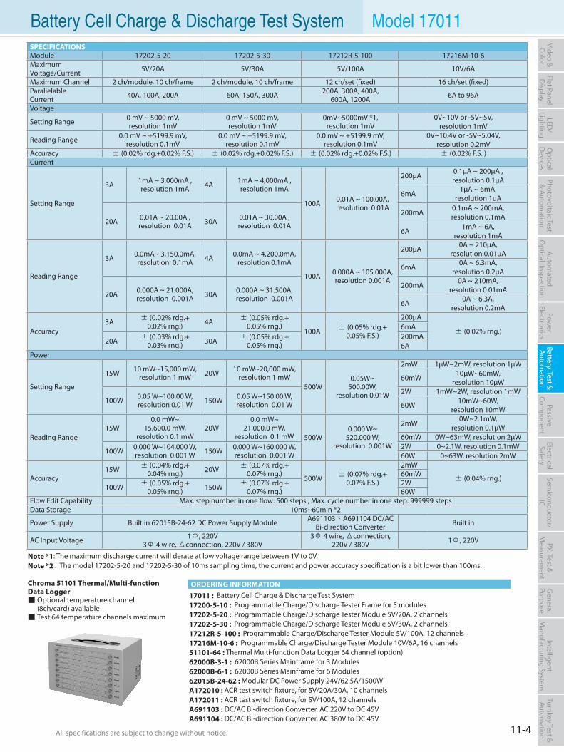
All specifications are subject to change without notice. All specifications are subject to change without notice. 11-4
Flat PanelD
isplayPow
er Electronics
Electrical Safety
General
PurposePassive
Component
Semiconductor/
ICBattery Test & Autom
ationAutom
atedO
ptical Inspection Photovoltaic Test
& Automation
PXI Test &
Measurem
ent Video & Color
LED/
LightingO
ptical D
evicesIntelligent
Manufacturing System
Turnkey Test & Autom
ation
17011 : Battery Cell Charge & Discharge Test System17200-5-10 : Programmable Charge/Discharge Tester Frame for 5 modules17202-5-20 : Programmable Charge/Discharge Tester Module 5V/20A, 2 channels 17202-5-30 : Programmable Charge/Discharge Tester Module 5V/30A, 2 channels 17212R-5-100 : Programmable Charge/Discharge Tester Module 5V/100A, 12 channels 17216M-10-6 : Programmable Charge/Discharge Tester Module 10V/6A, 16 channels 51101-64 : Thermal Multi-function Data Logger 64 channel (option)62000B-3-1 : 62000B Series Mainframe for 3 Modules 62000B-6-1 : 62000B Series Mainframe for 6 Modules 62015B-24-62 : Modular DC Power Supply 24V/62.5A/1500W A172010 : ACR test switch fixture, for 5V/20A/30A, 10 channelsA172011 : ACR test switch fixture, for 5V/100A, 12 channelsA691103 : DC/AC Bi-direction Converter, AC 220V to DC 45VA691104 : DC/AC Bi-direction Converter, AC 380V to DC 45V
ORDERING INFORMATIONChroma 51101 Thermal/Multi-functionData Logger Optional temperature channel (8ch/card) available Test 64 temperature channels maximum
Battery Cell Charge & Discharge Test System Model 17011
Note *1: The maximum discharge current will derate at low voltage range between 1V to 0V.Note *2 : The model 17202-5-20 and 17202-5-30 of 10ms sampling time, the current and power accuracy specification is a bit lower than 100ms.
SPECIFICATIONSModule 17202-5-20 17202-5-30 17212R-5-100 17216M-10-6Maximum Voltage/Current 5V/20A 5V/30A 5V/100A 10V/6A
Maximum Channel 2 ch/module, 10 ch/frame 2 ch/module, 10 ch/frame 12 ch/set (fixed) 16 ch/set (fixed)ParallelableCurrent 40A, 100A, 200A 60A, 150A, 300A 200A, 300A, 400A,
600A, 1200A 6A to 96A
Voltage
Setting Range 0 mV ~ 5000 mV, resolution 1mV
0 mV ~ 5000 mV, resolution 1mV
0mV~5000mV *1,resolution 1mV
0V~10V or -5V~5V,resolution 1mV
Reading Range 0.0 mV ~ +5199.9 mV, resolution 0.1mV
0.0 mV ~ +5199.9 mV, resolution 0.1mV
0.0 mV ~ +5199.9 mV, resolution 0.1mV
0V~10.4V or -5V~5.04V, resolution 0.2mV
Accuracy ± (0.02% rdg.+0.02% F.S.) ± (0.02% rdg.+0.02% F.S.) ± (0.02% rdg.+0.02% F.S.) ± (0.02% F.S. )Current
Setting Range
3A 1mA ~ 3,000mA ,resolution 1mA 4A 1mA ~ 4,000mA ,
resolution 1mA
100A 0.01A ~ 100.00A,resolution 0.01A
200µA 0.1µA ~ 200µA , resolution 0.1µA
6mA 1µA ~ 6mA,resolution 1uA
20A 0.01A ~ 20.00A , resolution 0.01A 30A 0.01A ~ 30.00A ,
resolution 0.01A
200mA 0.1mA ~ 200mA, resolution 0.1mA
6A 1mA ~ 6A,resolution 1mA
Reading Range
3A 0.0mA~ 3,150.0mA, resolution 0.1mA 4A 0.0mA ~ 4,200.0mA,
resolution 0.1mA
100A 0.000A ~ 105.000A,resolution 0.001A
200µA 0A ~ 210µA,resolution 0.01µA
6mA 0A ~ 6.3mA,resolution 0.2µA
20A 0.000A ~ 21.000A,resolution 0.001A 30A 0.000A ~ 31.500A,
resolution 0.001A
200mA 0A ~ 210mA,resolution 0.01mA
6A 0A ~ 6.3A,resolution 0.2mA
Accuracy3A ± (0.02% rdg.+
0.02% rng.) 4A ± (0.05% rdg.+0.05% rng.)
100A ± (0.05% rdg.+0.05% F.S.)
200µA
± (0.02% rng.)6mA
20A ± (0.03% rdg.+0.03% rng.) 30A ± (0.05% rdg.+
0.05% rng.)200mA6A
Power
Setting Range
15W 10 mW~15,000 mW, resolution 1 mW 20W 10 mW~20,000 mW,
resolution 1 mW 500W
0.05W~500.00W,
resolution 0.01W
2mW 1µW~2mW, resolution 1µW
60mW 10µW~60mW, resolution 10µW
100W 0.05 W~100.00 W,resolution 0.01 W 150W 0.05 W~150.00 W,
resolution 0.01 W
2W 1mW~2W, resolution 1mW
60W 10mW~60W, resolution 10mW
Reading Range 15W
0.0 mW~15,600.0 mW,
resolution 0.1 mW20W
0.0 mW~21,000.0 mW,
resolution 0.1 mW 500W0.000 W~
520.000 W, resolution 0.001W
2mW 0W~2.1mW, resolution 0.1µW
60mW 0W~63mW, resolution 2µW
100W 0.000 W~104.000 W, resolution 0.001 W 150W 0.000 W~160.000 W,
resolution 0.001 W2W 0~2.1W, resolution 0.1mW60W 0~63W, resolution 2mW
Accuracy15W ± (0.04% rdg.+
0.04% rng.) 20W ± (0.07% rdg.+0.07% rng.)
500W ± (0.07% rdg.+0.07% F.S.)
2mW
± (0.04% rng.)60mW
100W ± (0.05% rdg.+0.05% rng.) 150W ± (0.07% rdg.+
0.07% rng.)2W60W
Flow Edit Capability Max. step number in one flow: 500 steps ; Max. cycle number in one step: 999999 stepsData Storage 10ms~60min *2
Power Supply Built in 62015B-24-62 DC Power Supply Module A691103、A691104 DC/AC Bi-direction Converter Built in
AC Input Voltage 1Φ, 220V3Φ 4 wire, Δconnection, 220V / 380V
3Φ 4 wire, Δconnection,220V / 380V 1Φ, 220V
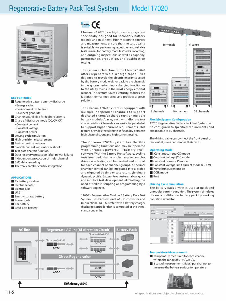
All specifications are subject to change without notice. All specifications are subject to change without notice.11-5
Regenerative Battery Pack Test System Model 17020
KEY FEATURES Regenerative battery energy discharge - Energy saving - Environment protection - Low heat generate Channels paralleled for higher currents Charge / discharge mode (CC, CV, CP) - Constant current - Constant voltage - Constant power Driving cycle simulation High precision measurement Fast current conversion Smooth current without over shoot Test data analysis function Data recovery protection (after power failure) Independent protection of multi-channel BMS data recording Thermal chamber control integration
APPLICATIONS EV battery module Electric scooter Electric bike UPS Energy storage battery Power tools Car battery Lead-acid battery
Chroma's 17020 is a high precision system specifically designed for secondary battery module and pack tests. Highly accurate sources and measurements ensure that the test quality is suitable for performing repetitive and reliable tests crucial for battery modules/packs, incoming, and outgoing inspections as well as capacity, per formance, production, and qualification testing.
The system architecture of the Chroma 17020 offers regenerat ive discharge capabi l i t ies designed to recycle the electric energy sourced by the battery module either back to the channels in the system performing a charging function or to the utility mains in the most energy efficient manner. This feature saves electricity, reduces the facilities thermal foot print, and provides a green solution.
The Chroma 17020 system is equipped with multiple independent channels to support dedicated charge/discharge tests on multiple battery modules/packs, each with discrete test characteristics. Channels can easily be paralleled to support higher current requirements. This feature provides the ultimate in flexibility between high channel count and high current testing.
T h e C h r o m a 1 7 0 2 0 s y s t e m h a s f l e x i b l e programming functions and may be operated w i t h C h r o m a's p o w e r f u l “B a t t e r y Pr o” software. With the Battery Pro software, cycling tests from basic charge or discharge to complex drive cycle testing can be created and utilized for each channel or channel groups. A thermal chamber control can be integrated into a profile and triggered by time or test results yielding a dynamic profile. Battery Pro's features allow quick and intuitive test development, eliminating the need of tedious scripting or programming by a software engineer.
17020's Regenerative Module / Battery Pack Test System uses bi-directional AC-DC converter and bi-directional DC-DC tester with a battery charge/ discharge controller that is composed of the threestandalone units.
8 channels 16 channels 32 channels
Terminals V-sense
Flexible System Configuration17020 Regenerative Battery Pack Test System canbe configured to specified requirements and expandable to 60 channels.
The driving cable can connect the front panel orrear outlet, users can choose their own.
Operating Mode Constant current (CC) mode Constant voltage (CV) mode Constant power (CP) mode Constant voltage-limit current mode (CC-CV) Waveform current mode DCIR mode Rest
Driving Cycle SimulationThe battery pack always is used at quick and unregular current condition. The system simulatesthe real condition on battery pack by working condition simulator.
Temperature Measurement Temperature measured for each channel within the range of 0~90±2 4 sets of measurements (Max) per channel to measure the battery surface temperature
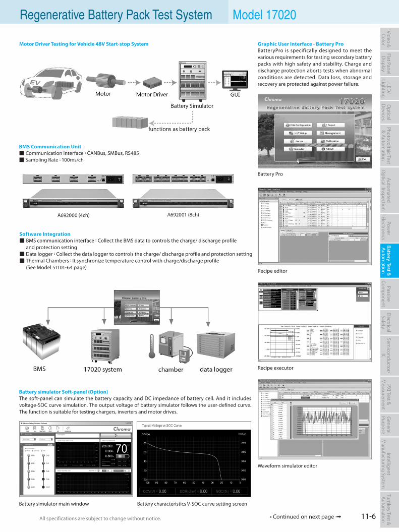
All specifications are subject to change without notice. All specifications are subject to change without notice. 11-6
Flat PanelD
isplayPow
er Electronics
Electrical Safety
General
PurposePassive
Component
Semiconductor/
ICBattery Test & Autom
ationAutom
atedO
ptical Inspection Photovoltaic Test
& Automation
PXI Test &
Measurem
ent Video & Color
LED/
LightingO
ptical D
evicesIntelligent
Manufacturing System
Turnkey Test & Autom
ation Regenerative Battery Pack Test System Model 17020
• Continued on next page
Battery Pro
Graphic User Interface - Battery ProBatteryPro is specifically designed to meet the various requirements for testing secondary battery packs with high safety and stability. Charge and discharge protection aborts tests when abnormal conditions are detected. Data loss, storage and recovery are protected against power failure.
Recipe editor
Recipe executor
Waveform simulator editor
A692001 (8ch)A692000 (4ch)
Software Integration BMS communication interface:Collect the BMS data to controls the charge/ discharge profile and protection setting Data logger:Collect the data logger to controls the charge/ discharge profile and protection setting Thermal Chambers:It synchronize temperature control with charge/discharge profile (See Model 51101-64 page)
Battery simulator main window
Battery simulator Soft-panel (Option)The soft-panel can simulate the battery capacity and DC impedance of battery cell. And it includes voltage-SOC curve simulation. The output voltage of battery simulator follows the user-defined curve. The function is suitable for testing chargers, inverters and motor drives.
Motor Driver Testing for Vehicle 48V Start-stop System
Battery characteristics V-SOC curve setting screen
BMS Communication Unit Communication interface:CANBus, SMBus, RS485 Sampling Rate:100ms/ch
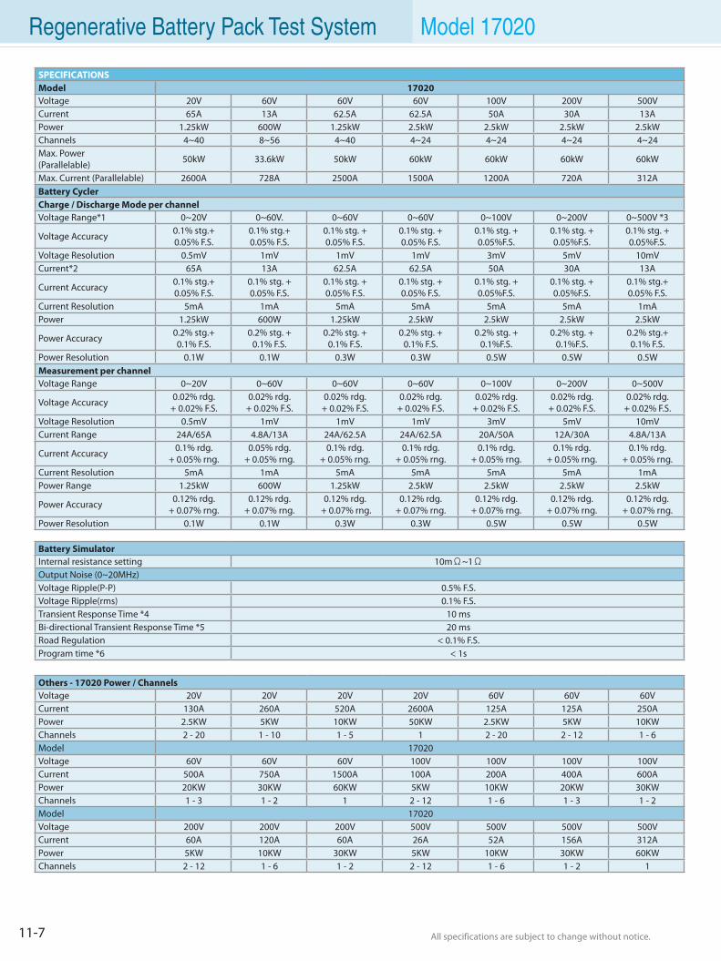
All specifications are subject to change without notice. All specifications are subject to change without notice.11-7
Regenerative Battery Pack Test System Model 17020
SPECIFICATIONSModel 17020Voltage 20V 60V 60V 60V 100V 200V 500VCurrent 65A 13A 62.5A 62.5A 50A 30A 13APower 1.25kW 600W 1.25kW 2.5kW 2.5kW 2.5kW 2.5kWChannels 4~40 8~56 4~40 4~24 4~24 4~24 4~24Max. Power(Parallelable) 50kW 33.6kW 50kW 60kW 60kW 60kW 60kW
Max. Current (Parallelable) 2600A 728A 2500A 1500A 1200A 720A 312ABattery CyclerCharge / Discharge Mode per channelVoltage Range*1 0~20V 0~60V. 0~60V 0~60V 0~100V 0~200V 0~500V *3
Voltage Accuracy 0.1% stg.+0.05% F.S.
0.1% stg.+0.05% F.S.
0.1% stg. +0.05% F.S.
0.1% stg. +0.05% F.S.
0.1% stg. +0.05%F.S.
0.1% stg. +0.05%F.S.
0.1% stg. +0.05%F.S.
Voltage Resolution 0.5mV 1mV 1mV 1mV 3mV 5mV 10mVCurrent*2 65A 13A 62.5A 62.5A 50A 30A 13A
Current Accuracy 0.1% stg.+0.05% F.S.
0.1% stg. +0.05% F.S.
0.1% stg. +0.05% F.S.
0.1% stg. +0.05% F.S.
0.1% stg. +0.05%F.S.
0.1% stg. +0.05%F.S.
0.1% stg.+0.05% F.S.
Current Resolution 5mA 1mA 5mA 5mA 5mA 5mA 1mAPower 1.25kW 600W 1.25kW 2.5kW 2.5kW 2.5kW 2.5kW
Power Accuracy 0.2% stg.+0.1% F.S.
0.2% stg. +0.1% F.S.
0.2% stg. +0.1% F.S.
0.2% stg. +0.1% F.S.
0.2% stg. +0.1%F.S.
0.2% stg. +0.1%F.S.
0.2% stg.+0.1% F.S.
Power Resolution 0.1W 0.1W 0.3W 0.3W 0.5W 0.5W 0.5WMeasurement per channelVoltage Range 0~20V 0~60V 0~60V 0~60V 0~100V 0~200V 0~500V
Voltage Accuracy 0.02% rdg. + 0.02% F.S.
0.02% rdg. + 0.02% F.S.
0.02% rdg. + 0.02% F.S.
0.02% rdg. + 0.02% F.S.
0.02% rdg. + 0.02% F.S.
0.02% rdg. + 0.02% F.S.
0.02% rdg. + 0.02% F.S.
Voltage Resolution 0.5mV 1mV 1mV 1mV 3mV 5mV 10mVCurrent Range 24A/65A 4.8A/13A 24A/62.5A 24A/62.5A 20A/50A 12A/30A 4.8A/13A
Current Accuracy 0.1% rdg. + 0.05% rng.
0.05% rdg. + 0.05% rng.
0.1% rdg. + 0.05% rng.
0.1% rdg. + 0.05% rng.
0.1% rdg. + 0.05% rng.
0.1% rdg. + 0.05% rng.
0.1% rdg. + 0.05% rng.
Current Resolution 5mA 1mA 5mA 5mA 5mA 5mA 1mAPower Range 1.25kW 600W 1.25kW 2.5kW 2.5kW 2.5kW 2.5kW
Power Accuracy 0.12% rdg. + 0.07% rng.
0.12% rdg. + 0.07% rng.
0.12% rdg. + 0.07% rng.
0.12% rdg. + 0.07% rng.
0.12% rdg. + 0.07% rng.
0.12% rdg. + 0.07% rng.
0.12% rdg. + 0.07% rng.
Power Resolution 0.1W 0.1W 0.3W 0.3W 0.5W 0.5W 0.5W
Others - 17020 Power / ChannelsVoltage 20V 20V 20V 20V 60V 60V 60VCurrent 130A 260A 520A 2600A 125A 125A 250APower 2.5KW 5KW 10KW 50KW 2.5KW 5KW 10KWChannels 2 - 20 1 - 10 1 - 5 1 2 - 20 2 - 12 1 - 6Model 17020Voltage 60V 60V 60V 100V 100V 100V 100VCurrent 500A 750A 1500A 100A 200A 400A 600APower 20KW 30KW 60KW 5KW 10KW 20KW 30KWChannels 1 - 3 1 - 2 1 2 - 12 1 - 6 1 - 3 1 - 2Model 17020Voltage 200V 200V 200V 500V 500V 500V 500VCurrent 60A 120A 60A 26A 52A 156A 312APower 5KW 10KW 30KW 5KW 10KW 30KW 60KWChannels 2 - 12 1 - 6 1 - 2 2 - 12 1 - 6 1 - 2 1
Battery SimulatorInternal resistance setting 10mΩ~1ΩOutput Noise (0~20MHz)Voltage Ripple(P-P) 0.5% F.S.Voltage Ripple(rms) 0.1% F.S.Transient Response Time *4 10 msBi-directional Transient Response Time *5 20 msRoad Regulation < 0.1% F.S.Program time *6 < 1s
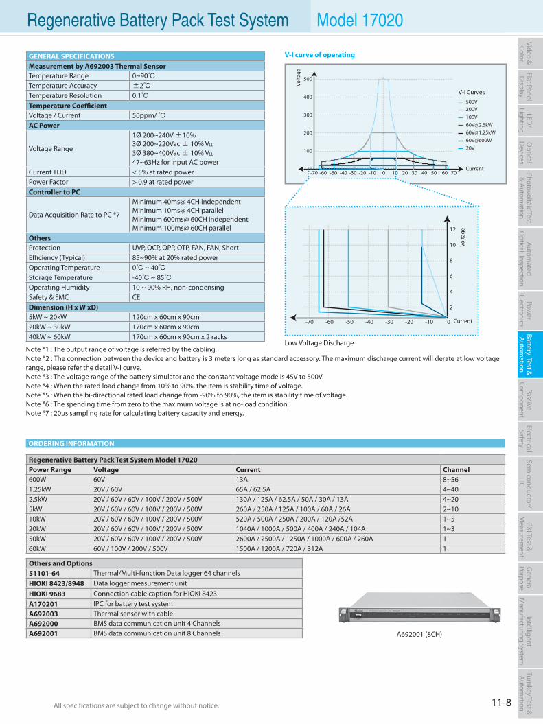
All specifications are subject to change without notice. All specifications are subject to change without notice. 11-8
Flat PanelD
isplayPow
er Electronics
Electrical Safety
General
PurposePassive
Component
Semiconductor/
ICBattery Test & Autom
ationAutom
atedO
ptical Inspection Photovoltaic Test
& Automation
PXI Test &
Measurem
ent Video & Color
LED/
LightingO
ptical D
evicesIntelligent
Manufacturing System
Turnkey Test & Autom
ation Regenerative Battery Pack Test System Model 17020
ORDERING INFORMATION
100
200
300
400
500
-70 -60 -50 -40 -30 -20 -10 0 10 20 30 40 50 60 70
Volta
ge
Current
V-I Curves
[email protected]@1.25kW60V@600W20V
500V
2
4
6
8
10
12
-70 -60 -50 -40 -30 -20 -10 0
Volta
ge
Current
Low Voltage Discharge
GENERAL SPECIFICATIONSMeasurement by A692003 Thermal SensorTemperature Range 0~90 Temperature Accuracy ±2 Temperature Resolution 0.1 Temperature CoefficientVoltage / Current 50ppm/ AC Power
Voltage Range
1Ø 200~240V ±10%3Ø 200~220Vac ± 10% VLL
3Ø 380~400Vac ± 10% VLL
47~63Hz for input AC powerCurrent THD < 5% at rated powerPower Factor > 0.9 at rated powerController to PC
Data Acquisition Rate to PC *7
Minimum 40ms@ 4CH independentMinimum 10ms@ 4CH parallelMinimum 600ms@ 60CH independentMinimum 100ms@ 60CH parallel
OthersProtection UVP, OCP, OPP, OTP, FAN, FAN, ShortEfficiency (Typical) 85~90% at 20% rated powerOperating Temperature 0 ~ 40Storage Temperature -40 ~ 85Operating Humidity 10 ~ 90% RH, non-condensingSafety & EMC CEDimension (H x W xD)5kW ~ 20kW 120cm x 60cm x 90cm20kW ~ 30kW 170cm x 60cm x 90cm40kW ~ 60kW 170cm x 60cm x 90cm x 2 racks
Regenerative Battery Pack Test System Model 17020Power Range Voltage Current Channel600W 60V 13A 8~561.25kW 20V / 60V 65A / 62.5A 4~402.5kW 20V / 60V / 60V / 100V / 200V / 500V 130A / 125A / 62.5A / 50A / 30A / 13A 4~205kW 20V / 60V / 60V / 100V / 200V / 500V 260A / 250A / 125A / 100A / 60A / 26A 2~1010kW 20V / 60V / 60V / 100V / 200V / 500V 520A / 500A / 250A / 200A / 120A /52A 1~520kW 20V / 60V / 60V / 100V / 200V / 500V 1040A / 1000A / 500A / 400A / 240A / 104A 1~350kW 20V / 60V / 60V / 100V / 200V / 500V 2600A / 2500A / 1250A / 1000A / 600A / 260A 160kW 60V / 100V / 200V / 500V 1500A / 1200A / 720A / 312A 1
Others and Options51101-64 Thermal/Multi-function Data logger 64 channelsHIOKI 8423/8948 Data logger measurement unitHIOKI 9683 Connection cable caption for HIOKI 8423A170201 IPC for battery test systemA692003 Thermal sensor with cable A692000 BMS data communication unit 4 ChannelsA692001 BMS data communication unit 8 Channels A692001 (8CH)
V-I curve of operating
Note *1 : The output range of voltage is referred by the cabling. Note *2 : The connection between the device and battery is 3 meters long as standard accessory. The maximum discharge current will derate at low voltage range, please refer the detail V-I curve.Note *3 : The voltage range of the battery simulator and the constant voltage mode is 45V to 500V.Note *4 : When the rated load change from 10% to 90%, the item is stability time of voltage.Note *5 : When the bi-directional rated load change from -90% to 90%, the item is stability time of voltage.Note *6 : The spending time from zero to the maximum voltage is at no-load condition.Note *7 : 20µs sampling rate for calculating battery capacity and energy.
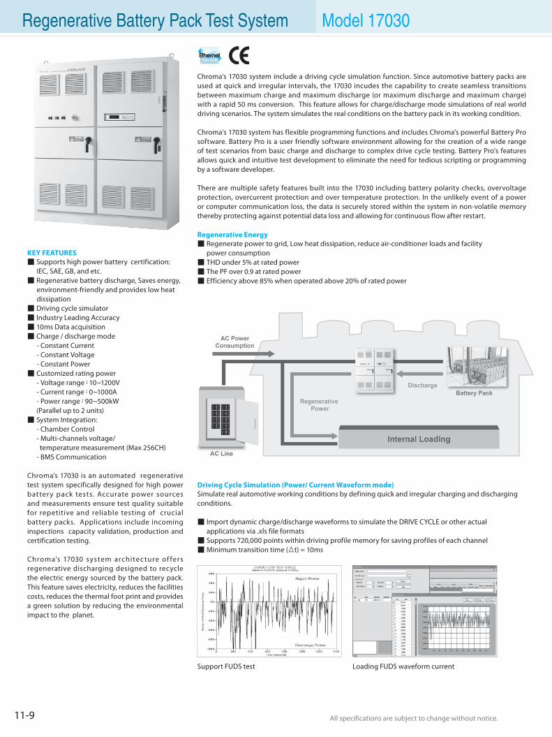
All specifications are subject to change without notice. All specifications are subject to change without notice.11-9
Regenerative Battery Pack Test System Model 17030
Driving Cycle Simulation (Power/ Current Waveform mode)Simulate real automotive working conditions by defining quick and irregular charging and discharging conditions.
Import dynamic charge/discharge waveforms to simulate the DRIVE CYCLE or other actual applications via .xls file formats Supports 720,000 points within driving profile memory for saving profiles of each channel Minimum transition time (Δt) = 10ms
Support FUDS test Loading FUDS waveform current
KEY FEATURES Supports high power battery certification: IEC, SAE, GB, and etc. Regenerative battery discharge, Saves energy, environment-friendly and provides low heat dissipation Driving cycle simulator Industry Leading Accuracy 10ms Data acquisition Charge / discharge mode - Constant Current - Constant Voltage - Constant Power Customized rating power - Voltage range:10~1200V - Current range:0~1000A - Power range:90~500kW (Parallel up to 2 units) System Integration: - Chamber Control - Multi-channels voltage/ temperature measurement (Max 256CH) - BMS Communication
Chroma's 17030 is an automated regenerative test system specifically designed for high power batter y pack tests. Accurate power sources and measurements ensure test quality suitable for repetitive and reliable testing of crucial battery packs. Applications include incoming inspections capacity validation, production and certification testing.
Chroma's 17030 system architec ture of fers regenerative discharging designed to recycle the electric energy sourced by the battery pack. This feature saves electricity, reduces the facilities costs, reduces the thermal foot print and provides a green solution by reducing the environmental impact to the planet.
Chroma's 17030 system include a driving cycle simulation function. Since automotive battery packs are used at quick and irregular intervals, the 17030 incudes the capability to create seamless transitions between maximum charge and maximum discharge (or maximum discharge and maximum charge) with a rapid 50 ms conversion. This feature allows for charge/discharge mode simulations of real world driving scenarios. The system simulates the real conditions on the battery pack in its working condition.
Chroma's 17030 system has flexible programming functions and includes Chroma's powerful Battery Pro software. Battery Pro is a user friendly software environment allowing for the creation of a wide range of test scenarios from basic charge and discharge to complex drive cycle testing. Battery Pro's features allows quick and intuitive test development to eliminate the need for tedious scripting or programming by a software developer.
There are multiple safety features built into the 17030 including battery polarity checks, overvoltage protection, overcurrent protection and over temperature protection. In the unlikely event of a power or computer communication loss, the data is securely stored within the system in non-volatile memory thereby protecting against potential data loss and allowing for continuous flow after restart.
Regenerative Energy Regenerate power to grid, Low heat dissipation, reduce air-conditioner loads and facility power consumption THD under 5% at rated power The PF over 0.9 at rated power Efficiency above 85% when operated above 20% of rated power
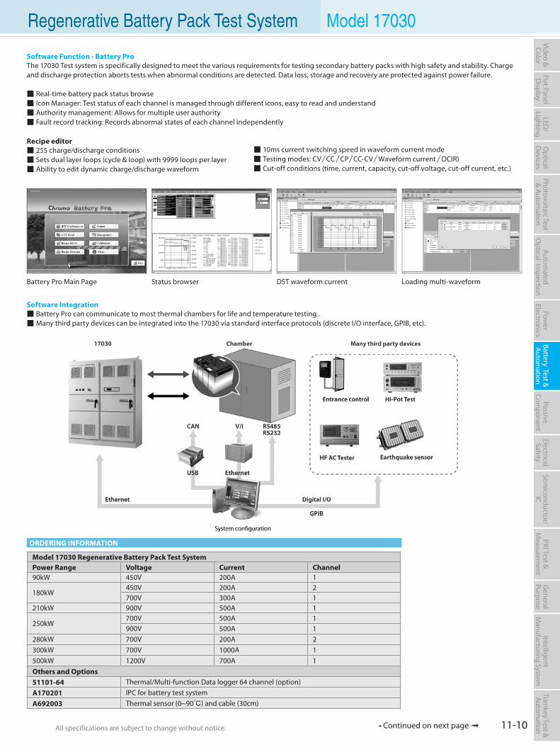
All specifications are subject to change without notice. All specifications are subject to change without notice. 11-10
Flat PanelD
isplayPow
er Electronics
Electrical Safety
General
PurposePassive
Component
Semiconductor/
ICBattery Test & Autom
ationAutom
atedO
ptical Inspection Photovoltaic Test
& Automation
PXI Test &
Measurem
ent Video & Color
LED/
LightingO
ptical D
evicesIntelligent
Manufacturing System
Turnkey Test & Autom
ation
Software Function - Battery ProThe 17030 Test system is specifically designed to meet the various requirements for testing secondary battery packs with high safety and stability. Charge and discharge protection aborts tests when abnormal conditions are detected. Data loss, storage and recovery are protected against power failure.
Real-time battery pack status browse Icon Manager: Test status of each channel is managed through different icons, easy to read and understand Authority management: Allows for multiple user authority Fault record tracking: Records abnormal states of each channel independently
Recipe editor 255 charge/discharge conditions Sets dual layer loops (cycle & loop) with 9999 loops per layer Ability to edit dynamic charge/discharge waveform
Battery Pro Main Page Status browser DST waveform current Loading multi-waveform
Software Integration Battery Pro can communicate to most thermal chambers for life and temperature testing . Many third party devices can be integrated into the 17030 via standard interface protocols (discrete I/O interface, GPIB, etc).
Regenerative Battery Pack Test System Model 17030
ORDERING INFORMATION
Model 17030 Regenerative Battery Pack Test System Power Range Voltage Current Channel90kW 450V 200A 1
180kW450V 200A 2700V 300A 1
210kW 900V 500A 1
250kW700V 500A 1900V 500A 1
280kW 700V 200A 2300kW 700V 1000A 1500kW 1200V 700A 1Others and Options51101-64 Thermal/Multi-function Data logger 64 channel (option)A170201 IPC for battery test systemA692003 Thermal sensor (0~90) and cable (30cm)
• Continued on next page
10ms current switching speed in waveform current mode Testing modes: CV/CC/CP/CC-CV/Waveform current/DCIR) Cut-off conditions (time, current, capacity, cut-off voltage, cut-off current, etc.)
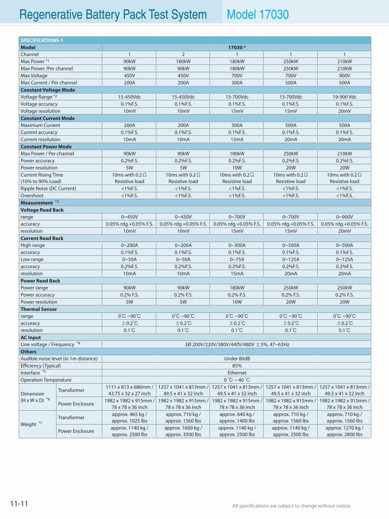
All specifications are subject to change without notice. All specifications are subject to change without notice.11-11
Regenerative Battery Pack Test System Model 17030
SPECIFICATIONS-1Model 17030 *Channel 1 2 1 1 1 Max Power *1 90kW 180kW 180kW 250kW 210kW Max Power /Per channel 90kW 90kW 180kW 250kW 210kW Max Voltage 450V 450V 700V 700V 900V Max Current / Per channel 200A 200A 300A 500A 500A Constant Voltage Mode Voltage Range *2 15-450Vdc 15-450Vdc 15-700Vdc 15-700Vdc 19-900 Vdc Voltage accuracy 0.1%F.S. 0.1%F.S. 0.1%F.S. 0.1%F.S. 0.1%F.S. Voltage resolution 10mV 10mV 15mV 15mV 20mV Constant Current Mode Maximum Current 200A 200A 300A 500A 500A Current accuracy 0.1%F.S. 0.1%F.S. 0.1%F.S. 0.1%F.S. 0.1%F.S. Current resolution 10mA 10mA 15mA 20mA 20mA Constant Power Mode Max Power / Per channel 90kW 90kW 180kW 250kW 210kW Power accuracy 0.2%F.S. 0.2%F.S. 0.2%F.S. 0.2%F.S. 0.2%F.S. Power resolution 5W 5W 10W 20W 20W Current Rising Time (10% to 90% Load)
10ms with 0.2ΩResistive load
10ms with 0.2ΩResistive load
10ms with 0.2ΩResistive load
10ms with 0.2ΩResistive load
10ms with 0.2ΩResistive load
Ripple Noise (DC Current) <1%F.S. <1%F.S. <1%F.S. <1%F.S. <1%F.S. Overshoot <1%F.S. <1%F.S. <1%F.S. <1%F.S. <1%F.S. Measurement *3
Voltage Read Back range 0~450V 0~450V 0~700V 0~700V 0~900V accuracy 0.05% rdg.+0.05% F.S. 0.05% rdg.+0.05% F.S. 0.05% rdg.+0.05% F.S. 0.05% rdg.+0.05% F.S. 0.05% rdg.+0.05% F.S. resolution 10mV 10mV 15mV 15mV 20mV Current Read Back High range 0~200A 0~200A 0~300A 0~500A 0~500A accuracy 0.1%F.S. 0.1%F.S. 0.1%F.S. 0.1%F.S. 0.1%F.S. Low range 0~50A 0~50A 0~75A 0~125A 0~125A accuracy 0.2%F.S. 0.2%F.S. 0.2%F.S. 0.2%F.S. 0.2%F.S. resolution 10mA 10mA 15mA 20mA 20mA Power Read Back Power range 90kW 90kW 180kW 250kW 250kW Power accuracy 0.2% F.S. 0.2% F.S. 0.2% F.S. 0.2% F.S. 0.2% F.S. Power resolution 5W 5W 10W 20W 20W Thermal Sensor range 0 ~90 0 ~90 0 ~90 0 ~90 0 ~90accuracy ±0.2 ±0.2 ±0.2 ±0.2 ±0.2resolution 0.1 0.1 0.1 0.1 0.1AC Input Line voltage / Frequency *4 3Ø 200V/220V/380V/440V/480V ±5%, 47~63Hz Others Audible noise level (in 1m distance) Under 80dB Efficiency (Typical) 85% Interface *5 Ethernet Operation Temperature 0 ~ 40
Dimension (H x W x D) *6
Transformer1111 x 813 x 686mm /
43.75 x 32 x 27 inch1257 x 1041 x 813mm /
49.5 x 41 x 32 inch1257 x 1041 x 813mm /
49.5 x 41 x 32 inch1257 x 1041 x 813mm /
49.5 x 41 x 32 inch1257 x 1041 x 813mm /
49.5 x 41 x 32 inch
Power Enclosure1982 x 1982 x 915mm /
78 x 78 x 36 inch1982 x 1982 x 915mm /
78 x 78 x 36 inch1982 x 1982 x 915mm /
78 x 78 x 36 inch1982 x 1982 x 915mm /
78 x 78 x 36 inch1982 x 1982 x 915mm /
78 x 78 x 36 inch
Weight *7Transformer
approx. 465 kg /approx. 1025 lbs
approx. 710 kg /approx. 1560 lbs
approx. 640 kg /approx. 1400 lbs
approx. 710 kg /approx. 1560 lbs
approx. 710 kg /approx. 1560 lbs
Power Enclosureapprox. 1140 kg /approx. 2500 lbs
approx. 1600 kg /approx. 3500 lbs
approx. 1140 kg /approx. 2500 lbs
approx. 1140 kg /approx. 2500 lbs
approx. 1270 kg /approx. 2800 lbs
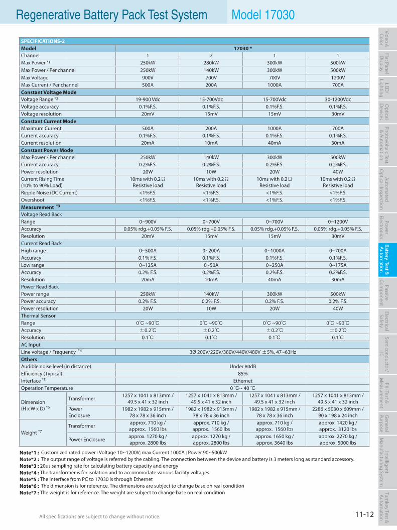
All specifications are subject to change without notice. All specifications are subject to change without notice. 11-12
Flat PanelD
isplayPow
er Electronics
Electrical Safety
General
PurposePassive
Component
Semiconductor/
ICBattery Test & Autom
ationAutom
atedO
ptical Inspection Photovoltaic Test
& Automation
PXI Test &
Measurem
ent Video & Color
LED/
LightingO
ptical D
evicesIntelligent
Manufacturing System
Turnkey Test & Autom
ation Regenerative Battery Pack Test System Model 17030
SPECIFICATIONS-2Model 17030 *Channel 1 2 1 1 Max Power *1 250kW 280kW 300kW 500kW Max Power / Per channel 250kW 140kW 300kW 500kW Max Voltage 900V 700V 700V 1200V Max Current / Per channel 500A 200A 1000A 700A Constant Voltage Mode Voltage Range *2 19-900 Vdc 15-700Vdc 15-700Vdc 30-1200Vdc Voltage accuracy 0.1%F.S. 0.1%F.S. 0.1%F.S. 0.1%F.S. Voltage resolution 20mV 15mV 15mV 30mV Constant Current Mode Maximum Current 500A 200A 1000A 700A Current accuracy 0.1%F.S. 0.1%F.S. 0.1%F.S. 0.1%F.S. Current resolution 20mA 10mA 40mA 30mA Constant Power Mode Max Power / Per channel 250kW 140kW 300kW 500kW Current accuracy 0.2%F.S. 0.2%F.S. 0.2%F.S. 0.2%F.S. Power resolution 20W 10W 20W 40W Current Rising Time(10% to 90% Load)
10ms with 0.2ΩResistive load
10ms with 0.2ΩResistive load
10ms with 0.2ΩResistive load
10ms with 0.2ΩResistive load
Ripple Noise (DC Current) <1%F.S. <1%F.S. <1%F.S. <1%F.S. Overshoot <1%F.S. <1%F.S. <1%F.S. <1%F.S. Measurement *3
Voltage Read Back Range 0~900V 0~700V 0~700V 0~1200V Accuracy 0.05% rdg.+0.05% F.S. 0.05% rdg.+0.05% F.S. 0.05% rdg.+0.05% F.S. 0.05% rdg.+0.05% F.S. Resolution 20mV 15mV 15mV 30mV Current Read Back High range 0~500A 0~200A 0~1000A 0~700A Accuracy 0.1% F.S. 0.1%F.S. 0.1%F.S. 0.1%F.S. Low range 0~125A 0~50A 0~250A 0~175A Accuracy 0.2% F.S. 0.2%F.S. 0.2%F.S. 0.2%F.S. Resolution 20mA 10mA 40mA 30mA Power Read Back Power range 250kW 140kW 300kW 500kW Power accuracy 0.2% F.S. 0.2% F.S. 0.2% F.S. 0.2% F.S. Power resolution 20W 10W 20W 40W Thermal Sensor Range 0 ~90 0 ~90 0 ~90 0 ~90Accuracy ±0.2 ±0.2 ±0.2 ±0.2Resolution 0.1 0.1 0.1 0.1 AC Input Line voltage / Frequency *4 3Ø 200V/220V/380V/440V/480V ±5%, 47~63Hz Others Audible noise level (in distance) Under 80dB Efficiency (Typical) 85% Interface *5 Ethernet Operation Temperature 0 ~ 40
Dimension(H x W x D) *6
Transformer 1257 x 1041 x 813mm / 49.5 x 41 x 32 inch
1257 x 1041 x 813mm / 49.5 x 41 x 32 inch
1257 x 1041 x 813mm / 49.5 x 41 x 32 inch
1257 x 1041 x 813mm / 49.5 x 41 x 32 inch
PowerEnclosure
1982 x 1982 x 915mm / 78 x 78 x 36 inch
1982 x 1982 x 915mm / 78 x 78 x 36 inch
1982 x 1982 x 915mm / 78 x 78 x 36 inch
2286 x 5030 x 609mm / 90 x 198 x 24 inch
Weight *7Transformer approx. 710 kg /
approx. 1560 lbsapprox. 710 kg /approx. 1560 lbs
approx. 710 kg /approx. 1560 lbs
approx. 1420 kg /approx. 3120 lbs
Power Enclosure approx. 1270 kg /approx. 2800 lbs
approx. 1270 kg /approx. 2800 lbs
approx. 1650 kg /approx. 3640 lbs
approx. 2270 kg /approx. 5000 lbs
Note*1 : Customized rated power : Voltage 10~1200V; max Current 1000A ; Power 90~500kWNote*2 : The output range of voltage is referred by the cabling. The connection between the device and battery is 3 meters long as standard accessory.Note*3 : 20us sampling rate for calculating battery capacity and energyNote*4 : The transformer is for isolation and to accommodate various facility voltagesNote*5 : The interface from PC to 17030 is through EthernetNote*6 : The dimension is for reference. The dimensions are subject to change base on real conditionNote*7 : The weight is for reference. The weight are subject to change base on real condition
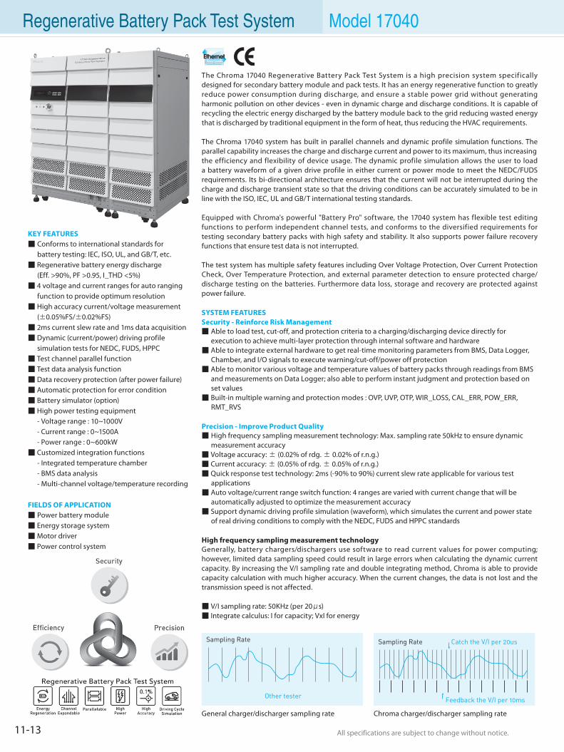
All specifications are subject to change without notice. All specifications are subject to change without notice.11-13
Regenerative Battery Pack Test System Model 17040
General charger/discharger sampling rate Chroma charger/discharger sampling rate
KEY FEATURES Conforms to international standards for battery testing: IEC, ISO, UL, and GB/T, etc. Regenerative battery energy discharge (Eff. >90%, PF >0.95, I_THD <5%) 4 voltage and current ranges for auto ranging function to provide optimum resolution High accuracy current/voltage measurement (±0.05%FS/±0.02%FS) 2ms current slew rate and 1ms data acquisition Dynamic (current/power) driving profile simulation tests for NEDC, FUDS, HPPC Test channel parallel function Test data analysis function Data recovery protection (after power failure) Automatic protection for error condition Battery simulator (option) High power testing equipment - Voltage range : 10~1000V - Current range : 0~1500A - Power range : 0~600kW Customized integration functions - Integrated temperature chamber - BMS data analysis - Multi-channel voltage/temperature recording
FIELDS OF APPLICATION Power battery module Energy storage system Motor driver Power control system
The Chroma 17040 Regenerative Battery Pack Test System is a high precision system specifically designed for secondary battery module and pack tests. It has an energy regenerative function to greatly reduce power consumption during discharge, and ensure a stable power grid without generating harmonic pollution on other devices - even in dynamic charge and discharge conditions. It is capable of recycling the electric energy discharged by the battery module back to the grid reducing wasted energy that is discharged by traditional equipment in the form of heat, thus reducing the HVAC requirements.
The Chroma 17040 system has built in parallel channels and dynamic profile simulation functions. The parallel capability increases the charge and discharge current and power to its maximum, thus increasingthe efficiency and flexibility of device usage. The dynamic profile simulation allows the user to load a battery waveform of a given drive profile in either current or power mode to meet the NEDC/FUDS requirements. Its bi-directional architecture ensures that the current will not be interrupted during the charge and discharge transient state so that the driving conditions can be accurately simulated to be in line with the ISO, IEC, UL and GB/T international testing standards.
Equipped with Chroma's powerful "Battery Pro" software, the 17040 system has flexible test editing functions to perform independent channel tests, and conforms to the diversified requirements for testing secondary battery packs with high safety and stability. It also supports power failure recovery functions that ensure test data is not interrupted.
The test system has multiple safety features including Over Voltage Protection, Over Current Protection Check, Over Temperature Protection, and external parameter detection to ensure protected charge/ discharge testing on the batteries. Furthermore data loss, storage and recovery are protected against power failure.
SYSTEM FEATURESSecurity - Reinforce Risk Management Able to load test, cut-off, and protection criteria to a charging/discharging device directly for execution to achieve multi-layer protection through internal software and hardware Able to integrate external hardware to get real-time monitoring parameters from BMS, Data Logger, Chamber, and I/O signals to execute warning/cut-off/power off protection Able to monitor various voltage and temperature values of battery packs through readings from BMS and measurements on Data Logger; also able to perform instant judgment and protection based on set values Built-in multiple warning and protection modes : OVP, UVP, OTP, WIR_LOSS, CAL_ERR, POW_ERR, RMT_RVS
Precision - Improve Product Quality High frequency sampling measurement technology: Max. sampling rate 50kHz to ensure dynamic measurement accuracy Voltage accuracy: ± (0.02% of rdg. ± 0.02% of r.n.g.) Current accuracy: ± (0.05% of rdg. ± 0.05% of r.n.g.) Quick response test technology: 2ms (-90% to 90%) current slew rate applicable for various test applications Auto voltage/current range switch function: 4 ranges are varied with current change that will be automatically adjusted to optimize the measurement accuracy Support dynamic driving profile simulation (waveform), which simulates the current and power state of real driving conditions to comply with the NEDC, FUDS and HPPC standards
High frequency sampling measurement technologyGenerally, battery chargers/dischargers use software to read current values for power computing; however, limited data sampling speed could result in large errors when calculating the dynamic current capacity. By increasing the V/I sampling rate and double integrating method, Chroma is able to provide capacity calculation with much higher accuracy. When the current changes, the data is not lost and the transmission speed is not affected.
V/I sampling rate: 50KHz (per 20μs) Integrate calculus: I for capacity; VxI for energy
Sampling Rate
Other tester
Catch the V/I per 20usSampling Rate
Feedback the V/I per 10ms
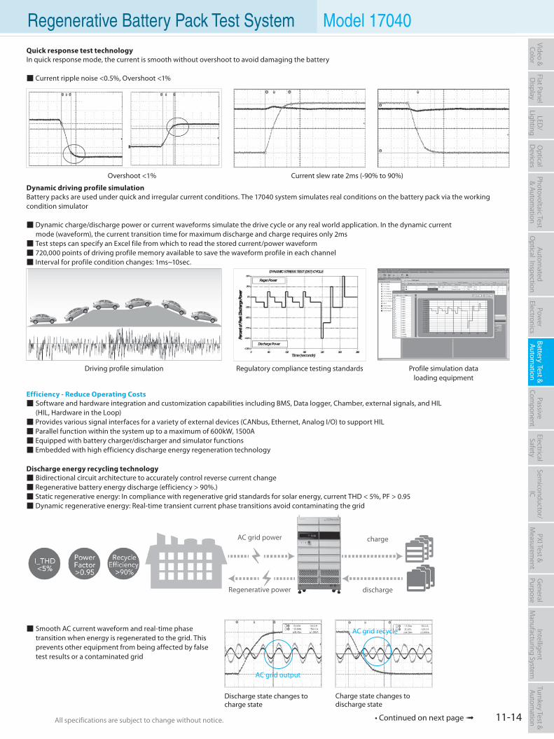
All specifications are subject to change without notice. All specifications are subject to change without notice. 11-14
Flat PanelD
isplayPow
er Electronics
Electrical Safety
General
PurposePassive
Component
Semiconductor/
ICBattery Test & Autom
ationAutom
atedO
ptical Inspection Photovoltaic Test
& Automation
PXI Test &
Measurem
ent Video & Color
LED/
LightingO
ptical D
evicesIntelligent
Manufacturing System
Turnkey Test & Autom
ation Regenerative Battery Pack Test System Model 17040Quick response test technologyIn quick response mode, the current is smooth without overshoot to avoid damaging the battery
Current ripple noise <0.5%, Overshoot <1%
Dynamic driving profile simulationBattery packs are used under quick and irregular current conditions. The 17040 system simulates real conditions on the battery pack via the working condition simulator
Dynamic charge/discharge power or current waveforms simulate the drive cycle or any real world application. In the dynamic current mode (waveform), the current transition time for maximum discharge and charge requires only 2ms Test steps can specify an Excel file from which to read the stored current/power waveform 720,000 points of driving profile memory available to save the waveform profile in each channel Interval for profile condition changes: 1ms~10sec.
Efficiency - Reduce Operating Costs Software and hardware integration and customization capabilities including BMS, Data logger, Chamber, external signals, and HIL (HIL, Hardware in the Loop) Provides various signal interfaces for a variety of external devices (CANbus, Ethernet, Analog I/O) to support HIL Parallel function within the system up to a maximum of 600kW, 1500A Equipped with battery charger/discharger and simulator functions Embedded with high efficiency discharge energy regeneration technology
Discharge energy recycling technology Bidirectional circuit architecture to accurately control reverse current change Regenerative battery energy discharge (efficiency > 90%.) Static regenerative energy: In compliance with regenerative grid standards for solar energy, current THD < 5%, PF > 0.95 Dynamic regenerative energy: Real-time transient current phase transitions avoid contaminating the grid
Smooth AC current waveform and real-time phase transition when energy is regenerated to the grid. This prevents other equipment from being affected by false test results or a contaminated grid
Current slew rate 2ms (-90% to 90%)Overshoot <1%
Driving profile simulation Regulatory compliance testing standards Profile simulation dataloading equipment
Discharge state changes tocharge state
Charge state changes todischarge state
AC grid output
AC grid recycle
charge
dischargeRegenerative power
AC grid power
• Continued on next page
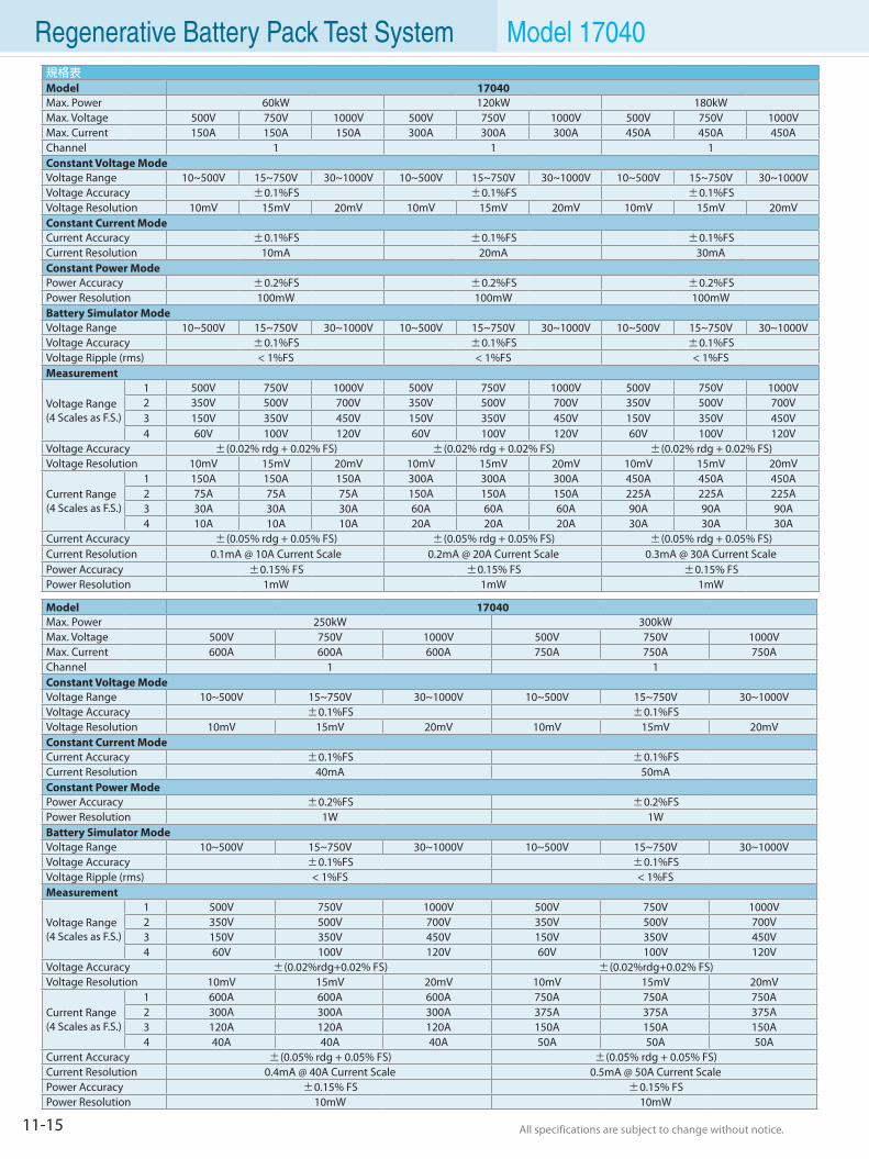
All specifications are subject to change without notice. All specifications are subject to change without notice.11-15
Regenerative Battery Pack Test System Model 17040規格表
Model 17040Max. Power 60kW 120kW 180kWMax. Voltage 500V 750V 1000V 500V 750V 1000V 500V 750V 1000VMax. Current 150A 150A 150A 300A 300A 300A 450A 450A 450AChannel 1 1 1Constant Voltage ModeVoltage Range 10~500V 15~750V 30~1000V 10~500V 15~750V 30~1000V 10~500V 15~750V 30~1000VVoltage Accuracy ±0.1%FS ±0.1%FS ±0.1%FSVoltage Resolution 10mV 15mV 20mV 10mV 15mV 20mV 10mV 15mV 20mVConstant Current ModeCurrent Accuracy ±0.1%FS ±0.1%FS ±0.1%FSCurrent Resolution 10mA 20mA 30mAConstant Power ModePower Accuracy ±0.2%FS ±0.2%FS ±0.2%FSPower Resolution 100mW 100mW 100mWBattery Simulator ModeVoltage Range 10~500V 15~750V 30~1000V 10~500V 15~750V 30~1000V 10~500V 15~750V 30~1000VVoltage Accuracy ±0.1%FS ±0.1%FS ±0.1%FSVoltage Ripple (rms) < 1%FS < 1%FS < 1%FSMeasurement
Voltage Range(4 Scales as F.S.)
1 500V 750V 1000V 500V 750V 1000V 500V 750V 1000V2 350V 500V 700V 350V 500V 700V 350V 500V 700V3 150V 350V 450V 150V 350V 450V 150V 350V 450V4 60V 100V 120V 60V 100V 120V 60V 100V 120V
Voltage Accuracy ±(0.02% rdg + 0.02% FS) ±(0.02% rdg + 0.02% FS) ±(0.02% rdg + 0.02% FS)Voltage Resolution 10mV 15mV 20mV 10mV 15mV 20mV 10mV 15mV 20mV
Current Range(4 Scales as F.S.)
1 150A 150A 150A 300A 300A 300A 450A 450A 450A2 75A 75A 75A 150A 150A 150A 225A 225A 225A3 30A 30A 30A 60A 60A 60A 90A 90A 90A4 10A 10A 10A 20A 20A 20A 30A 30A 30A
Current Accuracy ±(0.05% rdg + 0.05% FS) ±(0.05% rdg + 0.05% FS) ±(0.05% rdg + 0.05% FS)Current Resolution 0.1mA @ 10A Current Scale 0.2mA @ 20A Current Scale 0.3mA @ 30A Current ScalePower Accuracy ±0.15% FS ±0.15% FS ±0.15% FSPower Resolution 1mW 1mW 1mW
Model 17040Max. Power 250kW 300kWMax. Voltage 500V 750V 1000V 500V 750V 1000VMax. Current 600A 600A 600A 750A 750A 750AChannel 1 1Constant Voltage ModeVoltage Range 10~500V 15~750V 30~1000V 10~500V 15~750V 30~1000VVoltage Accuracy ±0.1%FS ±0.1%FSVoltage Resolution 10mV 15mV 20mV 10mV 15mV 20mVConstant Current ModeCurrent Accuracy ±0.1%FS ±0.1%FSCurrent Resolution 40mA 50mAConstant Power ModePower Accuracy ±0.2%FS ±0.2%FSPower Resolution 1W 1WBattery Simulator ModeVoltage Range 10~500V 15~750V 30~1000V 10~500V 15~750V 30~1000VVoltage Accuracy ±0.1%FS ±0.1%FSVoltage Ripple (rms) < 1%FS < 1%FSMeasurement
Voltage Range(4 Scales as F.S.)
1 500V 750V 1000V 500V 750V 1000V2 350V 500V 700V 350V 500V 700V3 150V 350V 450V 150V 350V 450V4 60V 100V 120V 60V 100V 120V
Voltage Accuracy ±(0.02%rdg+0.02% FS) ±(0.02%rdg+0.02% FS)Voltage Resolution 10mV 15mV 20mV 10mV 15mV 20mV
Current Range(4 Scales as F.S.)
1 600A 600A 600A 750A 750A 750A2 300A 300A 300A 375A 375A 375A3 120A 120A 120A 150A 150A 150A4 40A 40A 40A 50A 50A 50A
Current Accuracy ±(0.05% rdg + 0.05% FS) ±(0.05% rdg + 0.05% FS)Current Resolution 0.4mA @ 40A Current Scale 0.5mA @ 50A Current ScalePower Accuracy ±0.15% FS ±0.15% FSPower Resolution 10mW 10mW
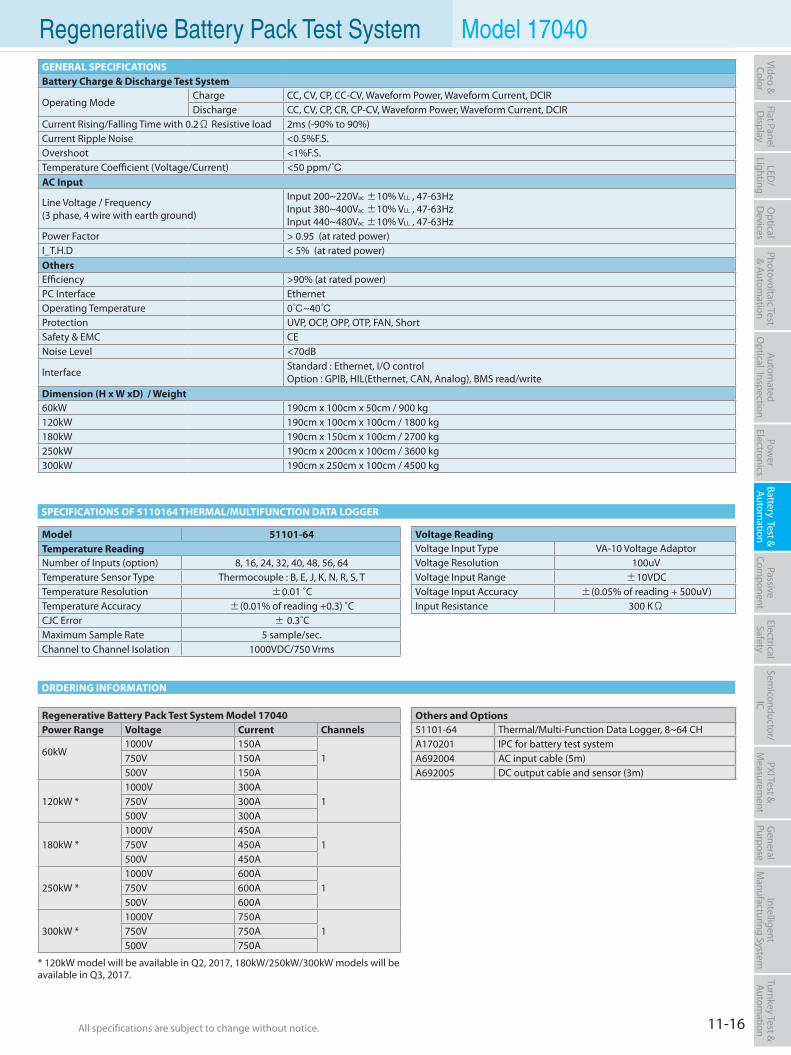
All specifications are subject to change without notice. All specifications are subject to change without notice. 11-16
Flat PanelD
isplayPow
er Electronics
Electrical Safety
General
PurposePassive
Component
Semiconductor/
ICBattery Test & Autom
ationAutom
atedO
ptical Inspection Photovoltaic Test
& Automation
PXI Test &
Measurem
ent Video & Color
LED/
LightingO
ptical D
evicesIntelligent
Manufacturing System
Turnkey Test & Autom
ation Regenerative Battery Pack Test System Model 17040GENERAL SPECIFICATIONSBattery Charge & Discharge Test System
Operating ModeCharge CC, CV, CP, CC-CV, Waveform Power, Waveform Current, DCIRDischarge CC, CV, CP, CR, CP-CV, Waveform Power, Waveform Current, DCIR
Current Rising/Falling Time with 0.2Ω Resistive load 2ms (-90% to 90%)Current Ripple Noise <0.5%F.S.Overshoot <1%F.S.Temperature Coefficient (Voltage/Current) <50 ppm/AC Input
Line Voltage / Frequency(3 phase, 4 wire with earth ground)
Input 200~220Vac ±10% VLL , 47-63HzInput 380~400Vac ±10% VLL , 47-63Hz Input 440~480Vac ±10% VLL , 47-63Hz
Power Factor > 0.95 (at rated power)I_T.H.D < 5% (at rated power)OthersEfficiency >90% (at rated power)PC Interface EthernetOperating Temperature 0~40Protection UVP, OCP, OPP, OTP, FAN, ShortSafety & EMC CENoise Level <70dB
lnterface Standard : Ethernet, I/O controlOption : GPIB, HIL(Ethernet, CAN, Analog), BMS read/write
Dimension (H x W xD) / Weight60kW 190cm x 100cm x 50cm / 900 kg120kW 190cm x 100cm x 100cm / 1800 kg180kW 190cm x 150cm x 100cm / 2700 kg250kW 190cm x 200cm x 100cm / 3600 kg300kW 190cm x 250cm x 100cm / 4500 kg
SPECIFICATIONS OF 5110164 THERMAL/MULTIFUNCTION DATA LOGGER
Voltage ReadingVoltage Input Type VA-10 Voltage AdaptorVoltage Resolution 100uVVoltage Input Range ±10VDCVoltage Input Accuracy ±(0.05% of reading + 500uV)Input Resistance 300 KΩ
Model 51101-64Temperature ReadingNumber of Inputs (option) 8, 16, 24, 32, 40, 48, 56, 64Temperature Sensor Type Thermocouple : B, E, J, K, N, R, S, TTemperature Resolution ±0.01 ˚CTemperature Accuracy ±(0.01% of reading +0.3) ˚CCJC Error ± 0.3˚CMaximum Sample Rate 5 sample/sec.Channel to Channel Isolation 1000VDC/750 Vrms
ORDERING INFORMATION
Regenerative Battery Pack Test System Model 17040Power Range Voltage Current Channels
60kW1000V 150A
1750V 150A500V 150A
120kW *1000V 300A
1750V 300A500V 300A
180kW *1000V 450A
1750V 450A500V 450A
250kW *1000V 600A
1750V 600A500V 600A
300kW *1000V 750A
1750V 750A500V 750A
Others and Options51101-64 Thermal/Multi-Function Data Logger, 8~64 CHA170201 IPC for battery test systemA692004 AC input cable (5m)A692005 DC output cable and sensor (3m)
* 120kW model will be available in Q2, 2017, 180kW/250kW/300kW models will be available in Q3, 2017.
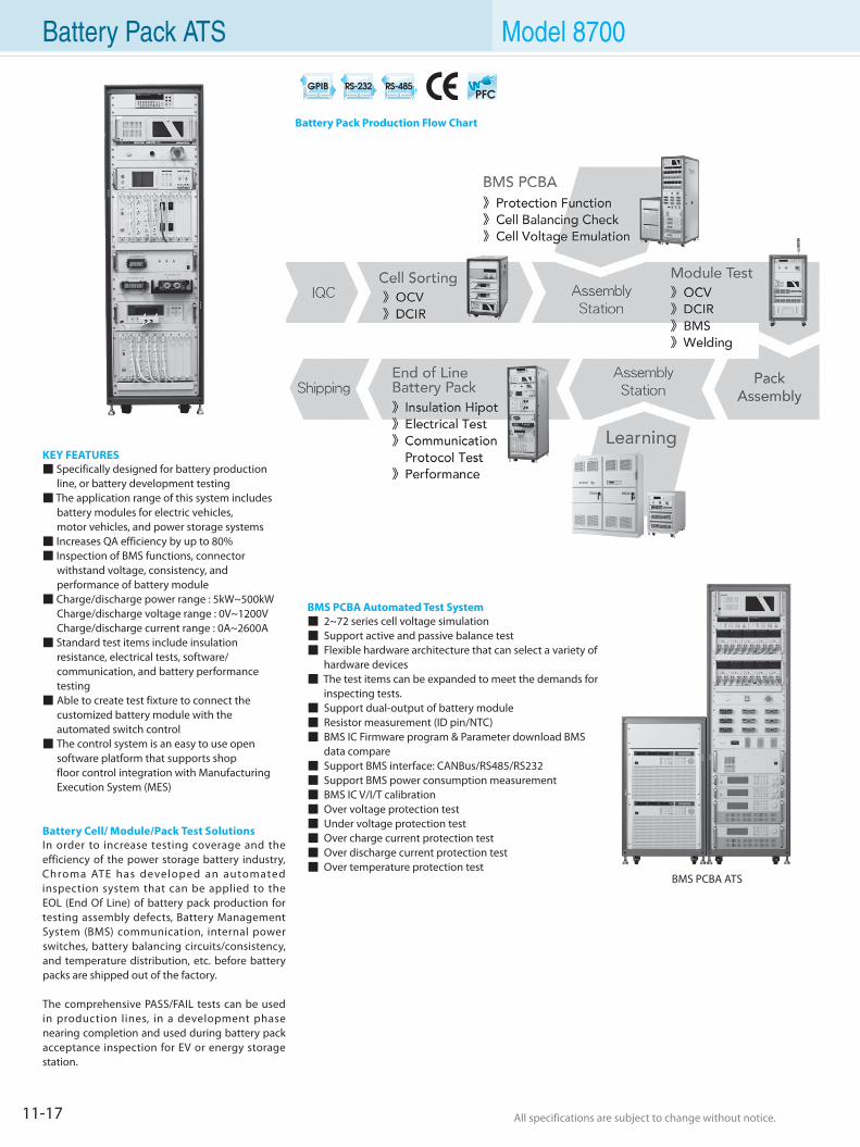
All specifications are subject to change without notice. All specifications are subject to change without notice.11-17
Battery Pack ATS Model 8700
KEY FEATURES Specifically designed for battery production
line, or battery development testing The application range of this system includes battery modules for electric vehicles, motor vehicles, and power storage systems Increases QA efficiency by up to 80% Inspection of BMS functions, connector withstand voltage, consistency, and
performance of battery module Charge/discharge power range : 5kW~500kW Charge/discharge voltage range : 0V~1200V Charge/discharge current range : 0A~2600A Standard test items include insulation
resistance, electrical tests, software/ communication, and battery performance testing Able to create test fixture to connect the customized battery module with the
automated switch control The control system is an easy to use open
software platform that supports shop floor control integration with Manufacturing Execution System (MES)
Battery Cell/ Module/Pack Test SolutionsIn order to increase testing coverage and the efficiency of the power storage battery industry, Chroma ATE has developed an automated inspection system that can be applied to the EOL (End Of Line) of battery pack production for testing assembly defects, Battery Management System (BMS) communication, internal power switches, battery balancing circuits/consistency, and temperature distribution, etc. before battery packs are shipped out of the factory.
The comprehensive PASS/FAIL tests can be used in production lines, in a development phase nearing completion and used during battery pack acceptance inspection for EV or energy storage station.
BMS PCBA ATS
BMS PCBA Automated Test System 2~72 series cell voltage simulation Support active and passive balance test Flexible hardware architecture that can select a variety of hardware devices The test items can be expanded to meet the demands for inspecting tests. Support dual-output of battery module Resistor measurement (ID pin/NTC) BMS IC Firmware program & Parameter download BMS data compare Support BMS interface: CANBus/RS485/RS232 Support BMS power consumption measurement BMS IC V/I/T calibration Over voltage protection test Under voltage protection test Over charge current protection test Over discharge current protection test Over temperature protection test
Battery Pack Production Flow Chart
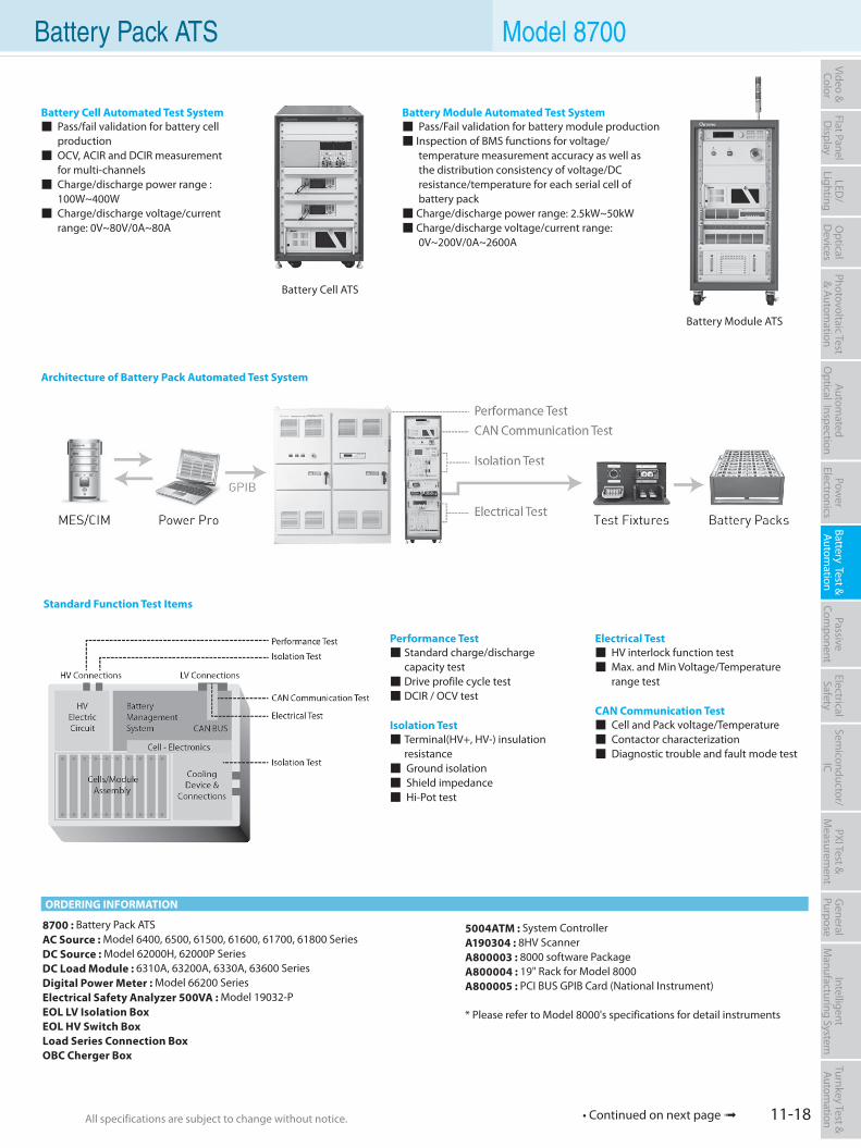
All specifications are subject to change without notice. All specifications are subject to change without notice. 11-18
Flat PanelD
isplayPow
er Electronics
Electrical Safety
General
PurposePassive
Component
Semiconductor/
ICBattery Test & Autom
ationAutom
atedO
ptical Inspection Photovoltaic Test
& Automation
PXI Test &
Measurem
ent Video & Color
LED/
LightingO
ptical D
evicesIntelligent
Manufacturing System
Turnkey Test & Autom
ation Battery Pack ATS Model 8700
Battery Module ATS
Battery Cell ATS
Battery Cell Automated Test System Pass/fail validation for battery cell production OCV, ACIR and DCIR measurement for multi-channels Charge/discharge power range : 100W~400W Charge/discharge voltage/current range: 0V~80V/0A~80A
Battery Module Automated Test System Pass/Fail validation for battery module production Inspection of BMS functions for voltage/ temperature measurement accuracy as well as the distribution consistency of voltage/DC resistance/temperature for each serial cell of battery pack Charge/discharge power range: 2.5kW~50kW Charge/discharge voltage/current range: 0V~200V/0A~2600A
• Continued on next page
Architecture of Battery Pack Automated Test System
Standard Function Test Items
Performance Test Standard charge/discharge capacity test Drive profile cycle test DCIR / OCV test
Isolation Test Terminal(HV+, HV-) insulation resistance Ground isolation Shield impedance Hi-Pot test
Electrical Test HV interlock function test Max. and Min Voltage/Temperature range test
CAN Communication Test Cell and Pack voltage/Temperature Contactor characterization Diagnostic trouble and fault mode test
ORDERING INFORMATION
8700 : Battery Pack ATSAC Source : Model 6400, 6500, 61500, 61600, 61700, 61800 SeriesDC Source : Model 62000H, 62000P SeriesDC Load Module : 6310A, 63200A, 6330A, 63600 SeriesDigital Power Meter : Model 66200 SeriesElectrical Safety Analyzer 500VA : Model 19032-PEOL LV Isolation BoxEOL HV Switch BoxLoad Series Connection BoxOBC Cherger Box
5004ATM : System ControllerA190304 : 8HV ScannerA800003 : 8000 software PackageA800004 : 19" Rack for Model 8000A800005 : PCI BUS GPIB Card (National Instrument)
* Please refer to Model 8000's specifications for detail instruments
Selection Guides 12-1
LCR Meter/Automatic Transformer Test System 12-3
Electrolytic Capacitor Analyzer 12-15
Programmable HF AC Tester 12-19
Milliohm Meter 12-21
Component Test Scanner 12-22
Automatic Test System 12-23
Options of Passive Component Test Instruments 12-35
Passive Component Test Solution
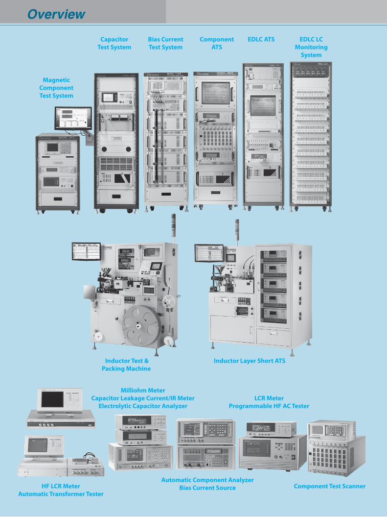
Overview
Inductor Test & Packing Machine
Inductor Layer Short ATS
MagneticComponentTest System
HF LCR MeterAutomatic Transformer Tester
EDLC ATSBias CurrentTest System
Milliohm MeterCapacitor Leakage Current/IR Meter
Electrolytic Capacitor Analyzer
Automatic Component AnalyzerBias Current Source Component Test Scanner
LCR MeterProgrammable HF AC Tester
EDLC LCMonitoring
System
ComponentATS
CapacitorTest System
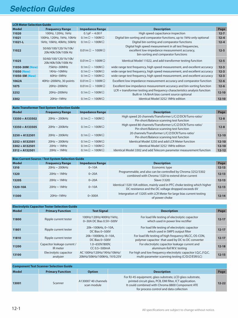
Selection Guides
All specifications are subject to change without notice. All specifications are subject to change without notice.
Electrolytic Capacitor Tester Selection GuideModel Primary Function Test Signal Description Page
11800 Ripple current tester100Hz/120Hz/400Hz/1kHz, 0~30A DC Bias 0.5V~500V
For load life testing of electrolytic capacitor which used in power line rectifier 12-17
11801 Ripple current tester20k~100kHz, 0~10A,
DC Bias 0~500VFor load life testing of electrolytic capacitor
which used in SMPS output filter 12-17
11810 Ripple current tester20k~1000kHz, 0~10A,
DC Bias 0~500VFor load life testing of high frequency MLCC, OS-CON, polymer capacitor that used by DC to DC converter 12-17
11200Capacitor leakage current /
IR meter1.0~650V/800V, CC 0.5~500mA
For electrolytic capacitor leakage current and aluminum-foil W.V. testing 12-18
13100Electrolytic capacitor
analyzerAC 100Hz/120Hz/1KHz/10kHz/20kHz/50kHz/100kHz, 1V/0.25V
For high and low frequency electrolytic capacitor I.Q.C.,F.Q.C. multi-parameter scanning testing (C/D/Z/ESR/LC) 12-15
Component Test Scanner Selection Guide
Model Primary Function Option Description Page
13001 ScannerA130007 40 channels
scan module
For RJ-45 equipment, glass substrate, LCD glass substrate, printed circuit glass, PCB, EMI filter, ICT application.
It could combined with Chroma 8800 Component ATE for process control and data collection
12-22
12-1
LCR Meter Selection GuideModel Frequency Range Impedance Range Description Page11020 100Hz, 120Hz, 1kHz 0.1pF ~ 4.00 F High speed capacitance inspection 12-711021 100Hz, 120Hz, 1kHz, 10kHz 0.1mΩ ~ 100MΩ Digital bin-sorting and comparator functions, up to 1kHz only optional 12-411021-L 1kHz, 10kHz, 40kHz, 50kHz 0.1mΩ ~ 100MΩ Digital bin-sorting and comparator functions 12-4
1102250/60/100/120/1k/10k/20k/40k/50k/100k Hz
0.01mΩ ~ 100MΩDigital high speed measurement in all test frequencies,
excellent low-impedance measurement accuracy, bin-sorting and comparator functions
12-5
1102550/60/100/120/1k/10k/20k/40k/50k/100k Hz
0.01mΩ ~ 100MΩ Identical Model 11022, and add transformer testing function 12-5
11050-30M (New) 75kHz~30MHz 0.1mΩ ~ 100MΩ wide range test frequency, high speed measurement, and excellent accuracy 12-311050 (New) 1KHz~10MHz 0.1mΩ ~ 100MΩ wide range test frequency, high speed measurement, and excellent accuracy 12-311050-5M (New) 60Hz~5MHz 0.1mΩ ~ 100MΩ wide range test frequency, high speed measurement, and excellent accuracy 12-3
1062A 40Hz~200kHz, 30 points 0.01mΩ ~ 100MΩ Excellent low impedance measurement accuracy and comparator function 12-6
1075 20Hz~200kHz 0.01mΩ ~ 100MΩ Excellent low impedance measurement accuracy and bin-sorting function 12-6
3252 20Hz~200kHz 0.1mΩ ~ 100MΩLCR + transformer testing and frequency characteristics analysis function
Built-in 1A/8mA bias current source optional 12-10
3302 20Hz~1MHz 0.1mΩ ~ 100MΩ Identical Model 3252 1MHz edition 12-10
Auto Transformer Test System Selection GuideModel Frequency Range Impedance Range Description Page
13350 + A133502 20Hz ~ 200kHz 0.1mΩ ~ 100MΩHigh speed 20 channels/Transformer L/C/Z/DCR/Turns-ratio/
Pin-short/Balance scanning test function 12-8
13350 + A133505 20Hz ~ 200kHz 0.1mΩ ~ 100MΩHigh speed 80 channels/Transformer L/C/Z/DCR/Turns-ratio/
Pin-short/Balance scanning test function 12-8
3250 + A132501 20Hz ~ 200kHz 0.1mΩ ~ 100MΩ20 channels/Transformer L/C/Z/DCR/Turns-ratio/
Pin-short/Balance scanning test function 12-10
3252 + A132501 20Hz ~ 200kHz 0.1mΩ ~ 100MΩ Identical Model 3250 and add LCR Meter function 12-103302 + A132501 20Hz ~ 1MHz 0.1mΩ ~ 100MΩ Identical Model 3252 1MHz edition 12-103312 + A132501 20Hz ~ 1MHz 0.1mΩ ~ 100MΩ Identical Model 3302 and add Telecom parameter measurement function 12-12
Bias Current Source / Test System Selection GuideModel Frequency Range Impedance Range Description Page1310 20Hz ~ 200kHz 0~10A Economic type 12-13
1320 20Hz ~ 1MHz 0~20AProgrammable, and also can be controlled by Chroma 3252/3302
combined with Chroma 1320 to extend drive current 12-13
1320S 20Hz ~ 1MHz 0~20A Slave (1320) 12-13
1320-10A 20Hz ~ 1MHz 0~10AIdentical 1320 10A edition, mainly used in PFC choke testing which higher
DC resistance and the DC voltage dropped exceeds 6V 12-13
11300 20Hz~1MHz 0~300AIntergration of 1320S with LCR Meter for large bias current testing
of power choke 12-14
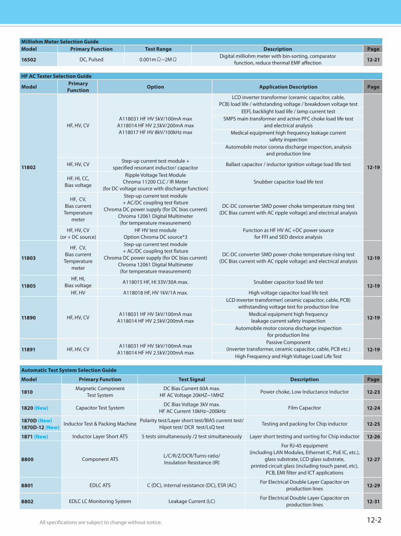
All specifications are subject to change without notice. All specifications are subject to change without notice. 12-2
HF AC Tester Selection Guide
ModelPrimary
FunctionOption Application Description Page
11802
HF, HV, CVA118031 HF HV 5kV/100mA max
A118014 HF HV 2.5kV/200mA maxA118017 HF HV 8kV/100kHz max
LCD inverter transformer (ceramic capacitor, cable, PCB) load life / withstanding voltage / breakdown voltage test
12-19
EEFl, backlight load life / lamp current testSMPS main transformer and active PFC choke load life test
and electrical analysisMedical equipment high frequency leakage current
safety inspectionAutomobile motor corona discharge inspection, analysis
and production line
HF, HV, CVStep-up current test module +
specified resonant inductor/ capacitorBallast capacitor / inductor ignition voltage load life test
HF, HI, CC,Bias voltage
Ripple Voltage Test ModuleChroma 11200 CLC / IR Meter
(for DC voltage source with discharge function)Snubber capacitor load life test
HF, CV,Bias current
Temperature meter
Step-up current test module+ AC/DC coupling test fixture
Chroma DC power supply (for DC bias current)Chroma 12061 Digital Multimeter(for temperature measurement)
DC-DC converter SMD power choke temperature rising test (DC Bias current with AC ripple voltage) and electrical analysis
HF, HV, CV(or + DC source)
HF HV test moduleOption Chroma DC source*3
Function as HF HV AC +DC power source for FFl and SED device analysis
11803
HF, CV,Bias current
Temperature meter
Step-up current test module+ AC/DC coupling test fixture
Chroma DC power supply (for DC bias current)Chroma 12061 Digital Multimeter(for temperature measurement)
DC-DC converter SMD power choke temperature rising test (DC Bias current with AC ripple voltage) and electrical analysis 12-19
11805HF, HI,
Bias voltageA118015 HF, HI 33V/30A max. Snubber capacitor load life test
12-19HF, HV A118018 HF, HV 1kV/1A max. High voltage capacitor load life test
11890 HF, HV, CVA118031 HF HV 5kV/100mA max
A118014 HF HV 2.5kV/200mA max
LCD inverter transformer( ceramic capacitor, cable, PCB) withstanding voltage test for production line
12-19Medical equipment high frequency
leakage current safety inspectionAutomobile motor corona discharge inspection
for production line
11891 HF, HV, CVA118031 HF HV 5kV/100mA max
A118014 HF HV 2.5kV/200mA max
Passive Component (inverter transformer, ceramic capacitor, cable, PCB etc.) 12-19
High Frequency and High Voltage Load Life Test
Automatic Test System Selection Guide
Model Primary Function Test Signal Description Page
1810Magnetic Component
Test SystemDC Bias Current 60A max.
HF AC Voltage 20kHZ~1MHZPower choke, Low Inductance Inductor 12-23
1820 (New) Capacitor Test SystemDC Bias Voltage 3kV max.
HF AC Current 10kHz~200kHzFilm Capacitor 12-24
1870D (New)1870D-12 (New)
Inductor Test & Packing MachinePolarity test/Layer short test/BIAS current test/
Hipot test/ DCR test/LsQ testTesting and packing for Chip inductor 12-25
1871 (New) Inductor Layer Short ATS 5 tests simultaneously /2 test simultaneously Layer short testing and sorting for Chip inductor 12-26
8800 Component ATSL/C/R/Z/DCR/Turns-ratio/Insulation Resistance (IR)
For RJ-45 equipment (including LAN Modules, Ethernet IC, PoE IC, etc.),
glass substrate, LCD glass substrate, printed circuit glass (including touch panel, etc),
PCB, EMI filter and ICT applications
12-27
8801 EDLC ATS C (DC), internal resistance (DC), ESR (AC)For Electrical Double Layer Capacitor on
production lines 12-29
8802 EDLC LC Monitoring System Leakage Current (LC)For Electrical Double Layer Capacitor on
production lines 12-31
Milliohm Meter Selection GuideModel Primary Function Test Range Description Page
16502 DC, Pulsed 0.001mΩ~2MΩDigital milliohm meter with bin-sorting, comparator
function, reduce thermal EMF affection 12-21
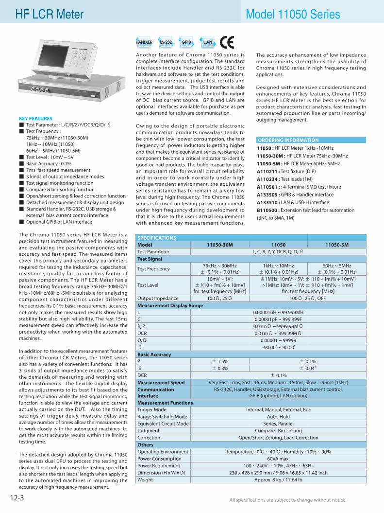
12-3 All specifications are subject to change without notice. All specifications are subject to change without notice.
Model 11050 Series
KEY FEATURES Test Parameter : L/C/R/Z/Y/DCR/Q/D/ θ Test Frequency : 75kHz ~ 30MHz (11050-30M) 1kHz ~ 10MHz (11050) 60Hz ~ 5MHz (11050-5M) Test Level : 10mV ~ 5V Basic Accuracy : 0.1% 7ms fast speed measurement 3 kinds of output impedance modes Test signal monitoring function Compare & bin-sorting function Open/short zeroing & load correction function Detached measurement & display unit design Standard Handler, RS-232C, USB storage & external bias current control interface Optional GPIB or LAN interface
The Chroma 11050 series HF LCR Meter is a precision test instrument featured in measuring and evaluating the passive components with accuracy and fast speed. The measured items cover the primary and secondary parameters required for testing the inductance, capacitance, resistance, quality factor and loss factor of passive components. The HF LCR Meter has a broad testing frequency range 75kHz~30MHz/1kHz~10MHz/60Hz~5MHz suitable for analyzing component characteristics under different frequencies. Its 0.1% basic measurement accuracy not only makes the measured results show high stability but also high reliability. The fast 15ms measurement speed can effectively increase the productivity when working with the automated machines.
In addition to the excellent measurement features of other Chroma LCR Meters, the 11050 series also has a variety of convenient functions. It has 3 kinds of output impedance modes to satisfy the demands of measuring and working with other instruments. The flexible digital display allows adjustments to its best fit based on the testing resolution while the test signal monitoring function is able to view the voltage and current actually carried on the DUT. Also the timing settings of trigger delay, measure delay and average number of times allow the measurements to work closely with the automated machines to get the most accurate results within the limited testing time.
The detached design adopted by Chroma 11050 series uses dual CPU to process the testing and display. It not only increases the testing speed but also shortens the test leads' length when applying to the automated machines in improving the accuracy of high frequency measurement.
11050 : HF LCR Meter 1kHz~10MHz
11050-30M : HF LCR Meter 75kHz~30MHz
11050-5M : HF LCR Meter 60Hz~5MHz
A110211 : Test fixture (DIP)
A110234 : Test leads (1M)
A110501 : : 4-Terminal SMD test fixture
A133509 : GPIB & Handler interface
A133510 : LAN & USB-H interface
B110500 : Extension test lead for automation (BNC to SMA, 1M)
Another feature of Chroma 11050 series is complete interface configuration. The standard inter faces include Handler and RS-232C for hardware and software to set the test conditions, trigger measurement, judge test results and collect measured data. The USB interface is able to save the device settings and control the output of DC bias current source. GPIB and LAN are optional interfaces available for purchase as per user's demand for software communication.
Owing to the design of portable electronic communication products nowadays tends to be thin with low power consumption, the test frequency of power inductors is getting higher and that makes the equivalent series resistance of component become a critical indicator to identify good or bad products. The buffer capacitor plays an important role for overall circuit reliability and in order to work normally under high voltage transient environment, the equivalent series resistance has to remain at a very low level during high frequency. The Chroma 11050 series is focused on testing passive components under high frequency during development so that it is close to the user's actual requirements with enhanced key measurement functions.
ORDERING INFORMATION
The accuracy enhancement of low impedance measurements strengthens the usabil ity of Chroma 11050 series in high frequency testing applications.
Designed with extensive considerations and enhancements of key features, Chroma 11050 series HF LCR Meter is the best selection for product characteristics analysis, fast testing in automated production line or parts incoming/outgoing management.
SPECIFICATIONSModel 11050-30M 11050 11050-5MTest Parameter L, C, R, Z, Y, DCR, Q, D, θ Test Signal
Test Frequency 75kHz ~ 30MHz± (0.1% + 0.01Hz)
1kHz ~ 10MHz ± (0.1% + 0.01Hz)
60Hz ~ 5MHz ± (0.1% + 0.01Hz)
Test Level10mV ~ 1V ;
± [(10 + fm)% + 10mV]fm: test frequency [MHz]
≦1MHz: 10mV ~ 5V; ± [(10 + fm)% + 10mV]>1MHz: 10mV ~ 1V; ± [(10 + fm)% + 1mV]
fm: test frequency [MHz]Output Impedance 100Ω, 25Ω 100Ω, 25Ω, OFFMeasurement Display RangeL 0.00001uH ~ 99.999MHC 0.00001pF ~ 999.999FR, Z 0.01mΩ ~ 9999.99MΩ DCR 0.01mΩ ~ 999.99MΩ Q, D 0.00001 ~ 99999θ -90.00˚ ~ 90.00˚ Basic AccuracyZ ± 1.5% ± 0.1%θ ± 0.3% ± 0.04˚ DCR ± 0.1% Measurement Speed Very Fast : 7ms, Fast : 15ms, Medium : 150ms, Slow : 295ms (1kHz)Communication Interface
RS-232C, Handler, USB storage, External bias current control, GPIB (option), LAN (option)
Measurement FunctionsTrigger Mode Internal, Manual, External, BusRange Switching Mode Auto, HoldEquivalent Circuit Mode Series, ParallelJudgment Compare, Bin-sortingCorrection Open/Short Zeroing, Load CorrectionOthersOperating Environment Temperature : 0 ~ 40 ; Humidity : 10% ~ 90%Power Consumption 60VA max.Power Requirement 100 ~ 240V ±10% , 47Hz ~ 63HzDimension (H x W x D) 230 x 428 x 290 mm / 9.06 x 16.85 x 11.42 inch Weight Approx. 8 kg / 17.64 lb
HF LCR Meter
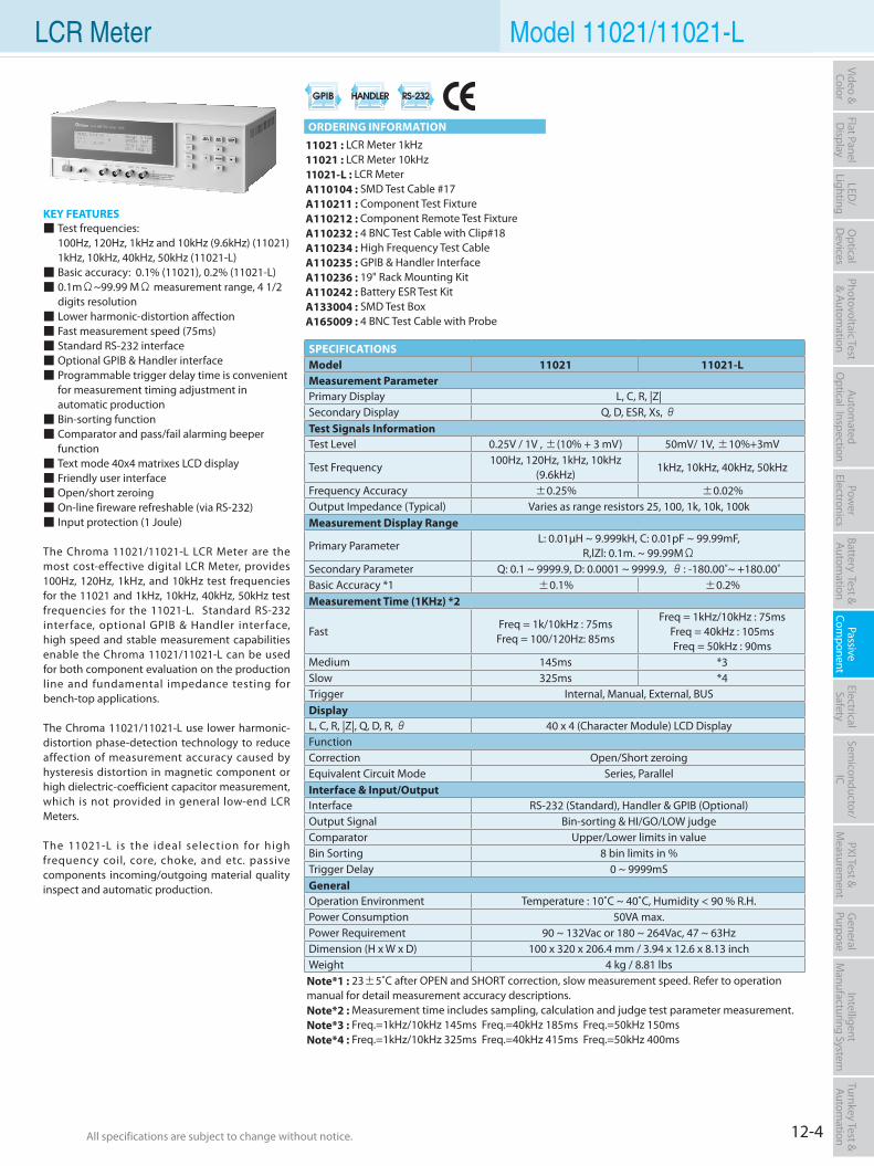
12-4All specifications are subject to change without notice. All specifications are subject to change without notice.
Flat PanelD
isplayPow
er Electronics
Electrical Safety
General
PurposePassive
Component
Semiconductor/
ICBattery Test & Autom
ationAutom
atedO
ptical Inspection Photovoltaic Test
& Automation
PXI Test &
Measurem
ent Video & Color
LED/
LightingO
ptical D
evicesIntelligent
Manufacturing System
Turnkey Test & Autom
ation
KEY FEATURES Test frequencies: 100Hz, 120Hz, 1kHz and 10kHz (9.6kHz) (11021) 1kHz, 10kHz, 40kHz, 50kHz (11021-L) Basic accuracy: 0.1% (11021), 0.2% (11021-L) 0.1mΩ~99.99 MΩ measurement range, 4 1/2
digits resolution Lower harmonic-distortion affection Fast measurement speed (75ms) Standard RS-232 interface Optional GPIB & Handler interface Programmable trigger delay time is convenient
for measurement timing adjustment in automatic production Bin-sorting function Comparator and pass/fail alarming beeper
function Text mode 40x4 matrixes LCD display Friendly user interface Open/short zeroing On-line fireware refreshable (via RS-232) Input protection (1 Joule)
The Chroma 11021/11021-L LCR Meter are the most cost-effective digital LCR Meter, provides 100Hz, 120Hz, 1kHz, and 10kHz test frequencies for the 11021 and 1kHz, 10kHz, 40kHz, 50kHz test frequencies for the 11021-L. Standard RS-232 interface, optional GPIB & Handler interface, high speed and stable measurement capabilities enable the Chroma 11021/11021-L can be used for both component evaluation on the production line and fundamental impedance testing for bench-top applications.
The Chroma 11021/11021-L use lower harmonic-distortion phase-detection technology to reduce affection of measurement accuracy caused by hysteresis distortion in magnetic component or high dielectric-coefficient capacitor measurement, which is not provided in general low-end LCR Meters.
The 11021-L is the ideal selection for high frequency coil, core, choke, and etc. passive components incoming/outgoing material quality inspect and automatic production.
11021 : LCR Meter 1kHz11021 : LCR Meter 10kHz11021-L : LCR MeterA110104 : SMD Test Cable #17A110211 : Component Test FixtureA110212 : Component Remote Test FixtureA110232 : 4 BNC Test Cable with Clip#18A110234 : High Frequency Test CableA110235 : GPIB & Handler InterfaceA110236 : 19" Rack Mounting KitA110242 : Battery ESR Test KitA133004 : SMD Test BoxA165009 : 4 BNC Test Cable with Probe
LCR Meter Model 11021/11021-L
ORDERING INFORMATION
SPECIFICATIONSModel 11021 11021-LMeasurement ParameterPrimary Display L, C, R, |Z|Secondary Display Q, D, ESR, Xs, θTest Signals InformationTest Level 0.25V / 1V , ±(10% + 3 mV) 50mV/ 1V, ±10%+3mV
Test Frequency 100Hz, 120Hz, 1kHz, 10kHz
(9.6kHz)1kHz, 10kHz, 40kHz, 50kHz
Frequency Accuracy ±0.25% ±0.02%Output Impedance (Typical) Varies as range resistors 25, 100, 1k, 10k, 100kMeasurement Display Range
Primary Parameter L: 0.01µH ~ 9.999kH, C: 0.01pF ~ 99.99mF,
R,lZl: 0.1m. ~ 99.99MΩSecondary Parameter Q: 0.1 ~ 9999.9, D: 0.0001 ~ 9999.9, θ: -180.00˚~ +180.00˚Basic Accuracy *1 ±0.1% ±0.2%Measurement Time (1KHz) *22)
FastFreq = 1k/10kHz : 75msFreq = 100/120Hz: 85ms
Freq = 1kHz/10kHz : 75msFreq = 40kHz : 105msFreq = 50kHz : 90ms
Medium 145ms *3Slow 325ms *4Trigger Internal, Manual, External, BUSDisplayL, C, R, |Z|, Q, D, R, θ 40 x 4 (Character Module) LCD DisplayFunctionCorrection Open/Short zeroingEquivalent Circuit Mode Series, ParallelInterface & Input/OutputInterface RS-232 (Standard), Handler & GPIB (Optional)Output Signal Bin-sorting & HI/GO/LOW judgeComparator Upper/Lower limits in valueBin Sorting 8 bin limits in %Trigger Delay 0 ~ 9999mSGeneralOperation Environment Temperature : 10˚C ~ 40˚C, Humidity < 90 % R.H.Power Consumption 50VA max.Power Requirement 90 ~ 132Vac or 180 ~ 264Vac, 47 ~ 63HzDimension (H x W x D) 100 x 320 x 206.4 mm / 3.94 x 12.6 x 8.13 inchWeight 4 kg / 8.81 lbsNote*1 : 23±5˚C after OPEN and SHORT correction, slow measurement speed. Refer to operation manual for detail measurement accuracy descriptions.Note*2 : Measurement time includes sampling, calculation and judge test parameter measurement.Note*3 : Freq.=1kHz/10kHz 145ms Freq.=40kHz 185ms Freq.=50kHz 150ms Note*4 : Freq.=1kHz/10kHz 325ms Freq.=40kHz 415ms Freq.=50kHz 400ms
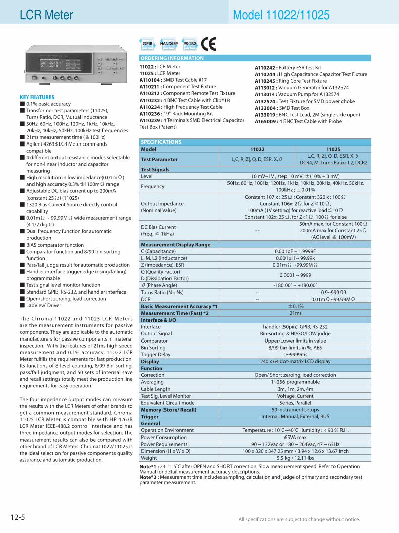
12-5 All specifications are subject to change without notice. All specifications are subject to change without notice.
11022 : LCR Meter11025 : LCR MeterA110104 : SMD Test Cable #17A110211 : Component Test FixtureA110212 : Component Remote Test FixtureA110232 : 4 BNC Test Cable with Clip#18A110234 : High Frequency Test CableA110236 : 19" Rack Mounting KitA110239 : 4 Terminals SMD Electrical Capacitor Test Box (Patent)
KEY FEATURES 0.1% basic accuracy Transformer test parameters (11025), Turns Ratio, DCR, Mutual Inductance 50Hz, 60Hz, 100Hz, 120Hz, 1kHz, 10kHz, 20kHz, 40kHz, 50kHz, 100kHz test frequencies 21ms measurement time (≧100Hz) Agilent 4263B LCR Meter commands compatible 4 different output resistance modes selectable for non-linear inductor and capacitor measuring High resolution in low impedance(0.01mΩ) and high accuracy 0.3% till 100mΩ range Adjustable DC bias current up to 200mA (constant 25Ω) (11025) 1320 Bias Current Source directly control capability 0.01mΩ ~ 99.99MΩ wide measurement range (4 1/2 digits) Dual frequency function for automatic production BIAS comparator function Comparator function and 8/99 bin-sorting function Pass/fail judge result for automatic production Handler interface trigger edge (rising/falling) programmable Test signal level monitor function Standard GPIB, RS-232, and handler interface Open/short zeroing, load correction LabView® Driver
The Chroma 11022 and 11025 LCR M eters are the measurement instruments for passive components. They are applicable to the automatic manufacturers for passive components in material inspection. With the features of 21ms high-speed measurement and 0.1% accuracy, 11022 LCR Meter fulfills the requirements for fast production. Its functions of 8-level counting, 8/99 Bin-sorting, pass/fail judgment, and 50 sets of internal save and recall settings totally meet the production line requirements for easy operation.
The four impedance output modes can measure the results with the LCR Meters of other brands to get a common measurement standard. Chroma 11025 LCR Meter is compatible with HP 4263B LCR Meter IEEE-488.2 control interface and has three impedance output modes for selection. The measurement results can also be compared with other brand of LCR Meters. Chroma11022/11025 is the ideal selection for passive components quality assurance and automatic production.
LCR Meter Model 11022/11025
Note*1 : 23 ± 5˚C after OPEN and SHORT correction. Slow measurement speed. Refer to Operation Manual for detail measurement accuracy descriptions. Note*2 : Measurement time includes sampling, calculation and judge of primary and secondary test parameter measurement.
SPECIFICATIONSModel 11022 11025
Test Parameter L,C, R,|Z|, Q, D, ESR, X,θL,C, R,|Z|, Q, D, ESR, X,θ
DCR4, M, Turns Ratio, L2, DCR2 Test SignalsLevel 10 mV~1V , step 10 mV; ±(10% + 3 mV)
Frequency50Hz, 60Hz, 100Hz, 120Hz, 1kHz, 10kHz, 20kHz, 40kHz, 50kHz,
100kHz ; ±0.01%
Output Impedance (Nominal Value)
Constant 107 x : 25Ω ; Constant 320 x : 100ΩConstant 106x: 2Ω,for Z≧10Ω,
100mA (1V setting) for reactive load≦10ΩConstant 102x: 25Ω, for Z<1Ω, 100Ω for else
DC Bias Current(Freq. ≧ 1kHz)
- -50mA max. for Constant 100Ω200mA max for Constant 25Ω
(AC level ≦ 100mV) Measurement Display RangeC (Capacitance) 0.001pF ~ 1.9999FL, M, L2 (Inductance) 0.001µH ~ 99.99k Z (Impedance), ESR 0.01mΩ ~99.99MΩQ (Quality Factor)D (Dissipation Factor)
0.0001 ~ 9999
θ(Phase Angle) -180.00˚ ~ +180.00˚Turns Ratio (Np:Ns) -- 0.9~999.99DCR -- 0.01mΩ~99.99MΩBasic Measurement Accuracy *1 ±0.1%Measurement Time (Fast) *2 21msInterface & I/OInterface handler (50pin), GPIB, RS-232Output Signal Bin-sorting & HI/GO/LOW judgeComparator Upper/Lower limits in valueBin Sorting 8/99 bin limits in %, ABSTrigger Delay 0~9999msDisplay 240 x 64 dot-matrix LCD displayFunctionCorrection Open/ Short zeroing, load correctionAveraging 1~256 programmableCable Length 0m, 1m, 2m, 4mTest Sig. Level Monitor Voltage, CurrentEquivalent Circuit mode Series, ParallelMemory (Store/ Recall) 50 instrument setupsTrigger Internal, Manual, External, BUSGeneralOperation Environment Temperature : 10˚C~40˚C Humidity : < 90 % R.H.Power Consumption 65VA maxPower Requirements 90 ~ 132Vac or 180 ~ 264Vac, 47 ~ 63HzDimension (H x W x D) 100 x 320 x 347.25 mm / 3.94 x 12.6 x 13.67 inchWeight 5.5 kg / 12.11 lbs
A110242 : Battery ESR Test KitA110244 : High Capacitance Capacitor Test FixtureA110245 : Ring Core Test FixtureA113012 : Vacuum Generator for A132574A113014 : Vacuum Pump for A132574A132574 : Test Fixture for SMD power chokeA133004 : SMD Test BoxA133019 : BNC Test Lead, 2M (single side open)A165009 : 4 BNC Test Cable with Probe
ORDERING INFORMATION
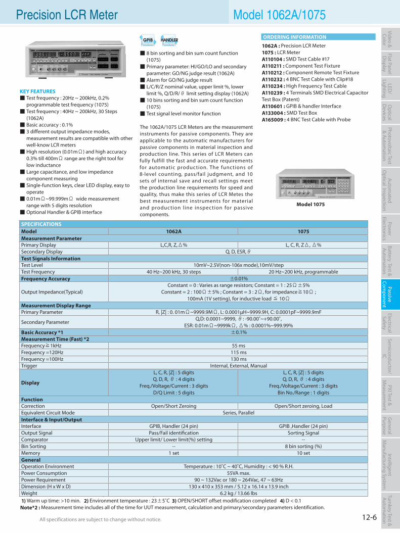
12-6All specifications are subject to change without notice. All specifications are subject to change without notice.
Flat PanelD
isplayPow
er Electronics
Electrical Safety
General
PurposePassive
Component
Semiconductor/
ICBattery Test & Autom
ationAutom
atedO
ptical Inspection Photovoltaic Test
& Automation
PXI Test &
Measurem
ent Video & Color
LED/
LightingO
ptical D
evicesIntelligent
Manufacturing System
Turnkey Test & Autom
ation
8 bin sorting and bin sum count function (1075) Primary parameter: HI/GO/LO and secondary parameter: GO/NG judge result (1062A) Alarm for GO/NG judge result L/C/R/Z nominal value, upper limit %, lower limit %, Q/D/R/θ limit setting display (1062A) 10 bins sorting and bin sum count function (1075) Test signal level monitor function
The 1062A/1075 LCR Meters are the measurement instruments for passive components. They are applicable to the automatic manufacturers for passive components in material inspection and production line. This series of LCR Meters can fully fulfill the fast and accurate requirements for automatic production. The functions of 8-level counting, pass/fail judgment, and 10 sets of internal save and recall settings meet the production line requirements for speed and quality, thus make this series of LCR Metes the best measurement instruments for material and production l ine inspection for passive components.
KEY FEATURES Test frequency : 20Hz ~ 200kHz, 0.2% programmable test frequency (1075) Test frequency : 40Hz ~ 200kHz, 30 Steps (1062A) Basic accuracy : 0.1% 3 different output impedance modes, measurement results are compatible with other well-know LCR meters High resolution (0.01mΩ) and high accuracy 0.3% till 400mΩ range are the right tool for low inductance Large capacitance, and low impedance component measuring Single-function keys, clear LED display, easy to operate 0.01mΩ~99.999mΩ wide measurement range with 5 digits resolution Optional Handler & GPIB interface
1062A : Precision LCR Meter1075 : LCR MeterA110104 : SMD Test Cable #17A110211 : Component Test FixtureA110212 : Component Remote Test FixtureA110232 : 4 BNC Test Cable with Clip#18A110234 : High Frequency Test CableA110239 : 4 Terminals SMD Electrical Capacitor Test Box (Patent)A110601 : GPIB & handler InterfaceA133004 : SMD Test BoxA165009 : 4 BNC Test Cable with Probe
Model 1075
Precision LCR Meter Model 1062A/1075
Note*1 : The specification of accuracy is under the following conditions: 1) Warm up time: >10 min. 2) Environment temperature : 23±5˚C 3) OPEN/SHORT offset modification completed 4) D < 0.1Note*2 : Measurement time includes all of the time for UUT measurement, calculation and primary/secondary parameters identification.
SPECIFICATIONSModel 1062A 1075Measurement ParameterPrimary Display L,C,R, Z,Δ% L, C, R, ZΔ, Δ%Secondary Display Q, D, ESR,θTest Signals InformationTest Level 10mV~2.5V(non-106x mode),10mV/stepTest Frequency 40 Hz~200 kHz, 30 steps 20 Hz~200 kHz, programmableFrequency Accuracy ±0.01%
Output Impedance(Typical)Constant = 0 : Varies as range resistors; Constant = 1 : 25Ω±5%
Constant = 2 : 100Ω±5% ; Constant = 3 : 2Ω, for impedance≧10Ω ; 100mA (1V setting), for inductive load ≦ 10Ω
Measurement Display RangePrimary Parameter R, |Z| : 0. 01mΩ~9999.9MΩ, L: 0.0001µH~9999.9H, C: 0.0001pF~9999.9mF
Secondary ParameterQ,D: 0.0001~9999, θ: -90.00˚~+90.00˚,
ESR: 0.01mΩ~9999kΩ, Δ% : 0.0001%~999.99%Basic Accuracy *1 ±0.1%Measurement Time (Fast) *2Frequency≧1kHz 55 msFrequency =120Hz 115 msFrequency =100Hz 130 msTrigger Internal, External, Manual
Display
L, C, R, |Z| : 5 digitsQ, D, R, θ : 4 digits
Freq./Voltage/Current : 3 digitsD/Q Limit : 5 digits
L, C, R, |Z| : 5 digitsQ, D, R, θ : 4 digits
Freq./Voltage/Current : 3 digitsBin No./Range : 1 digits
FunctionCorrection Open/Short Zeroing Open/Short zeroing, LoadEquivalent Circuit Mode Series, ParallelInterface & Input/OutputInterface GPIB, Handler (24 pin) GPIB ,Handler (24 pin)Output Signal Pass/Fail identification Sorting SignalComparator Upper limit/ Lower limit(%) setting --Bin Sorting -- 8 bin sorting (%)Memory 1 set 10 setGeneralOperation Environment Temperature : 10˚C ~ 40˚C, Humidity : < 90 % R.H.Power Consumption 55VA max.Power Requirement 90 ~ 132Vac or 180 ~ 264Vac, 47 ~ 63HzDimension (H x W x D) 130 x 410 x 353 mm / 5.12 x 16.14 x 13.9 inchWeight 6.2 kg / 13.66 lbs
ORDERING INFORMATION
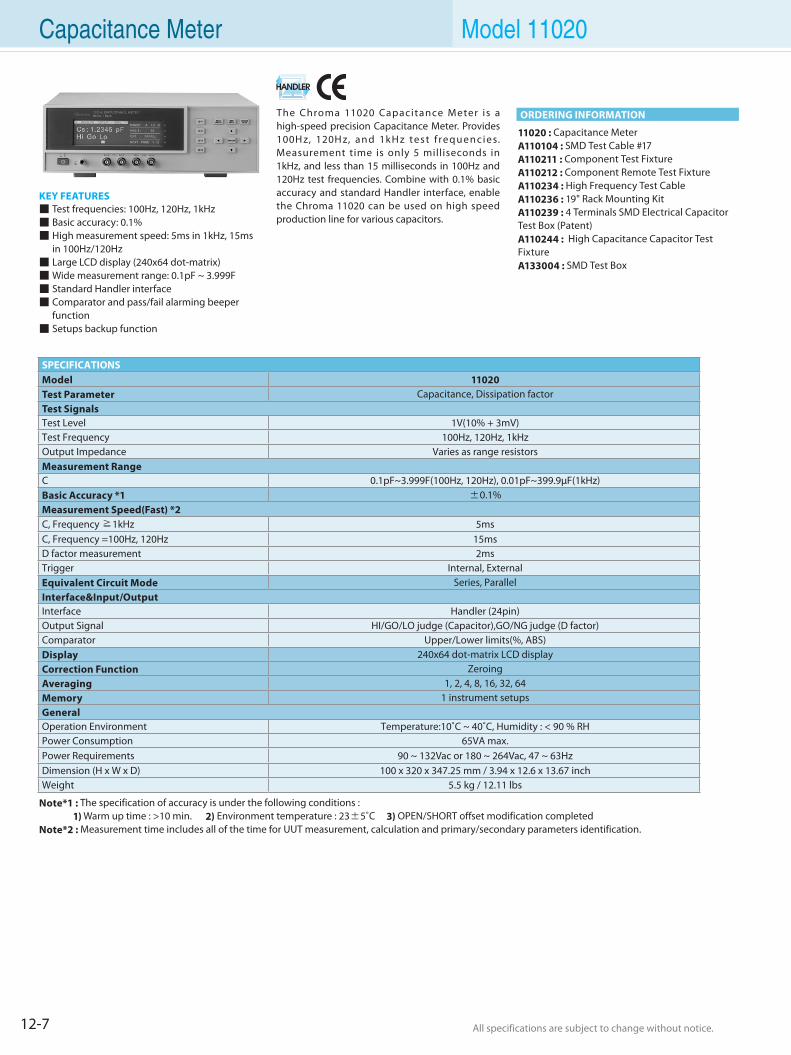
12-7 All specifications are subject to change without notice. All specifications are subject to change without notice.
The Chroma 11020 Capacitance Meter is a high-speed precision Capacitance Meter. Provides 100H z, 120H z, and 1kH z test f requencies. Measurement time is only 5 milliseconds in 1kHz, and less than 15 milliseconds in 100Hz and 120Hz test frequencies. Combine with 0.1% basic accuracy and standard Handler interface, enable the Chroma 11020 can be used on high speed production line for various capacitors.
KEY FEATURES Test frequencies: 100Hz, 120Hz, 1kHz Basic accuracy: 0.1% High measurement speed: 5ms in 1kHz, 15ms in 100Hz/120Hz Large LCD display (240x64 dot-matrix) Wide measurement range: 0.1pF ~ 3.999F Standard Handler interface Comparator and pass/fail alarming beeper function Setups backup function
11020 : Capacitance MeterA110104 : SMD Test Cable #17A110211 : Component Test FixtureA110212 : Component Remote Test FixtureA110234 : High Frequency Test CableA110236 : 19" Rack Mounting KitA110239 : 4 Terminals SMD Electrical Capacitor Test Box (Patent)A110244 : High Capacitance Capacitor Test FixtureA133004 : SMD Test Box
Capacitance Meter Model 11020
Note*1 : The specification of accuracy is under the following conditions : 1) Warm up time : >10 min. 2) Environment temperature : 23±5˚C 3) OPEN/SHORT offset modification completedNote*2 : Measurement time includes all of the time for UUT measurement, calculation and primary/secondary parameters identification.
SPECIFICATIONSModel 11020Test Parameter Capacitance, Dissipation factorTest SignalsTest Level 1V(10% + 3mV)Test Frequency 100Hz, 120Hz, 1kHzOutput Impedance Varies as range resistorsMeasurement RangeC 0.1pF~3.999F(100Hz, 120Hz), 0.01pF~399.9µF(1kHz)Basic Accuracy *1 ±0.1%Measurement Speed(Fast) *2C, Frequency ≧1kHz 5msC, Frequency =100Hz, 120Hz 15msD factor measurement 2msTrigger Internal, ExternalEquivalent Circuit Mode Series, ParallelInterface&Input/OutputInterface Handler (24pin)Output Signal HI/GO/LO judge (Capacitor),GO/NG judge (D factor)Comparator Upper/Lower limits(%, ABS)Display 240x64 dot-matrix LCD displayCorrection Function ZeroingAveraging 1, 2, 4, 8, 16, 32, 64Memory 1 instrument setupsGeneralOperation Environment Temperature:10˚C ~ 40˚C, Humidity : < 90 % RHPower Consumption 65VA max.Power Requirements 90 ~ 132Vac or 180 ~ 264Vac, 47 ~ 63HzDimension (H x W x D) 100 x 320 x 347.25 mm / 3.94 x 12.6 x 13.67 inchWeight 5.5 kg / 12.11 lbs
ORDERING INFORMATION
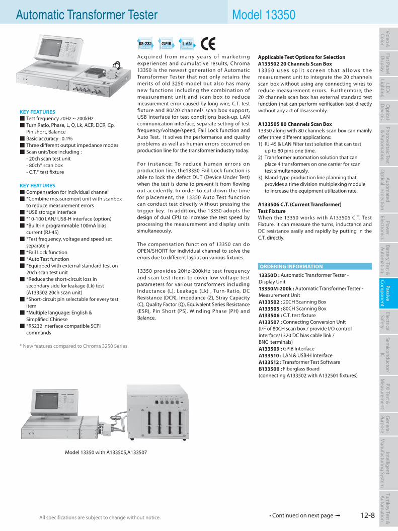
12-8All specifications are subject to change without notice. All specifications are subject to change without notice.
Flat PanelD
isplayPow
er Electronics
Electrical Safety
General
PurposePassive
Component
Semiconductor/
ICBattery Test & Autom
ationAutom
atedO
ptical Inspection Photovoltaic Test
& Automation
PXI Test &
Measurem
ent Video & Color
LED/
LightingO
ptical D
evicesIntelligent
Manufacturing System
Turnkey Test & Autom
ation
A c q u i r e d f r o m m a n y y e a r s o f m a r k e t i n g experiences and cumulative results, Chroma 13350 is the newest generation of Automatic Transformer Tester that not only retains the merits of old 3250 model but also has many new functions including the combination of measurement unit and scan box to reduce measurement error caused by long wire, C.T. test fixture and 80/20 channels scan box support, USB interface for test conditions back-up, LAN communication interface, separate setting of test frequency/voltage/speed, Fail Lock function and Auto Test. It solves the performance and quality problems as well as human errors occurred on production line for the transformer industry today.
Fo r i n s t a n ce: To re d u ce h u m a n e r ro r s o n production line, the13350 Fail Lock function is able to lock the defect DUT (Device Under Test) when the test is done to prevent it from flowing out accidently. In order to cut down the time for placement, the 13350 Auto Test function can conduct test directly without pressing the trigger key. In addition, the 13350 adopts the design of dual CPU to increase the test speed by processing the measurement and display units simultaneously.
The compensation function of 13350 can do OPEN/SHORT for individual channel to solve the errors due to different layout on various fixtures.
13350 provides 20Hz-200kHz test frequency and scan test items to cover low voltage test parameters for various transformers including Inductance (L), Leakage (Lk) , Turn-Ratio, DC Resistance (DCR), Impedance (Z), Stray Capacity (C), Quality Factor (Q), Equivalent Series Resistance (ESR), Pin Short (PS), Winding Phase (PH) and Balance.
KEY FEATURES Test frequency 20Hz ~ 200kHz Turn Ratio, Phase, L, Q, Lk, ACR, DCR, Cp, Pin short, Balance Basic accuracy : 0.1% Three different output impedance modes Scan unit/box including : - 20ch scan test unit - 80ch* scan box - C.T.* test fixture
KEY FEATURES Compensation for individual channel *Combine measurement unit with scanbox to reduce measurement errors *USB storage interface *10-100 LAN/ USB-H interface (option) *Built-in programmable 100mA bias current (RJ-45) *Test frequency, voltage and speed set separately *Fail Lock function *Auto Test function *Equipped with external standard test on 20ch scan test unit *Reduce the short-circuit loss in secondary side for leakage (Lk) test (A133502 20ch scan unit) *Short-circuit pin selectable for every test item *Multiple language: English & Simplified Chinese *RS232 interface compatible SCPI commands
* New features compared to Chroma 3250 Series
13350D : Automatic Transformer Tester - Display Unit13350M-200k : Automatic Transformer Tester - Measurement UnitA133502 : 20CH Scanning BoxA133505 : 80CH Scanning BoxA133506 : C.T. test fixtureA133507 : Connecting Conversion Unit (I/F of 80CH scan box / provide I/O control interface/1320 DC bias cable link /BNC terminals) A133509 : GPIB InterfaceA133510 : LAN & USB-H InterfaceA133512 : Transformer Test SoftwareB133500 : Fiberglass Board(connecting A133502 with A132501 fixtures)
Model 13350 with A133505,A133507
Automatic Transformer Tester Model 13350
ORDERING INFORMATION
Applicable Test Options for SelectionA133502 20 Channels Scan Box1 3 3 5 0 u s e s s p l i t s c r e e n t h a t a l l o w s t h e measurement unit to integrate the 20 channels scan box without using any connecting wires to reduce measurement errors. Furthermore, the 20 channels scan box has external standard test function that can perform verification test directly without any act of disassembly.
A133505 80 Channels Scan Box 13350 along with 80 channels scan box can mainly offer three different applications:1) RJ-45 & LAN Filter test solution that can test up to 80 pins one time. 2) Transformer automation solution that can place 4 transformers on one carrier for scan test simultaneously. 3) Island-type production line planning that provides a time division multiplexing module to increase the equipment utilization rate.
A133506 C.T. (Current Transformer)Test FixtureWhen the 13350 works with A133506 C.T. Test Fixture, it can measure the turns, inductance and DC resistance easily and rapidly by putting in the C.T. directly.
• Continued on next page
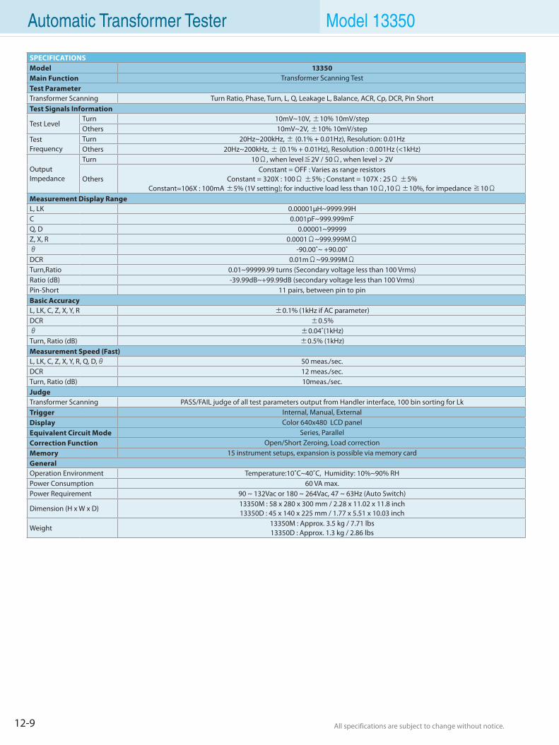
12-9 All specifications are subject to change without notice. All specifications are subject to change without notice.
Automatic Transformer Tester Model 13350
SPECIFICATIONSModel 13350Main Function Transformer Scanning TestTest ParameterTransformer Scanning Turn Ratio, Phase, Turn, L, Q, Leakage L, Balance, ACR, Cp, DCR, Pin ShortTest Signals Information
Test LevelTurn 10mV~10V, ±10% 10mV/stepOthers 10mV~2V, ±10% 10mV/step
TestFrequency
Turn 20Hz~200kHz, ± (0.1% + 0.01Hz), Resolution: 0.01HzOthers 20Hz~200kHz, ± (0.1% + 0.01Hz), Resolution : 0.001Hz (<1kHz)
Output Impedance
Turn 10Ω, when level≦2V / 50Ω, when level > 2V
OthersConstant = OFF : Varies as range resistors
Constant = 320X : 100Ω ±5% ; Constant = 107X : 25Ω ±5%Constant=106X : 100mA ±5% (1V setting); for inductive load less than 10Ω,10Ω±10%, for impedance ≧10Ω
Measurement Display RangeL, LK 0.00001µH~9999.99HC 0.001pF~999.999mFQ, D 0.00001~99999Z, X, R 0.0001Ω~999.999MΩθ -90.00˚~ +90.00˚DCR 0.01mΩ~99.999MΩTurn,Ratio 0.01~99999.99 turns (Secondary voltage less than 100 Vrms)Ratio (dB) -39.99dB~+99.99dB (secondary voltage less than 100 Vrms)Pin-Short 11 pairs, between pin to pinBasic AccuracyL, LK, C, Z, X, Y, R ±0.1% (1kHz if AC parameter)DCR ±0.5%θ ±0.04˚(1kHz)Turn, Ratio (dB) ±0.5% (1kHz)Measurement Speed (Fast)L, LK, C, Z, X, Y, R, Q, D,θ 50 meas./sec.DCR 12 meas./sec.Turn, Ratio (dB) 10meas./sec.JudgeTransformer Scanning PASS/FAIL judge of all test parameters output from Handler interface, 100 bin sorting for LkTrigger Internal, Manual, ExternalDisplay Color 640x480 LCD panelEquivalent Circuit Mode Series, ParallelCorrection Function Open/Short Zeroing, Load correctionMemory 15 instrument setups, expansion is possible via memory cardGeneralOperation Environment Temperature:10˚C~40˚C, Humidity: 10%~90% RHPower Consumption 60 VA max.Power Requirement 90 ~ 132Vac or 180 ~ 264Vac, 47 ~ 63Hz (Auto Switch)
Dimension (H x W x D)13350M : 58 x 280 x 300 mm / 2.28 x 11.02 x 11.8 inch13350D : 45 x 140 x 225 mm / 1.77 x 5.51 x 10.03 inch
Weight13350M : Approx. 3.5 kg / 7.71 lbs13350D : Approx. 1.3 kg / 2.86 lbs
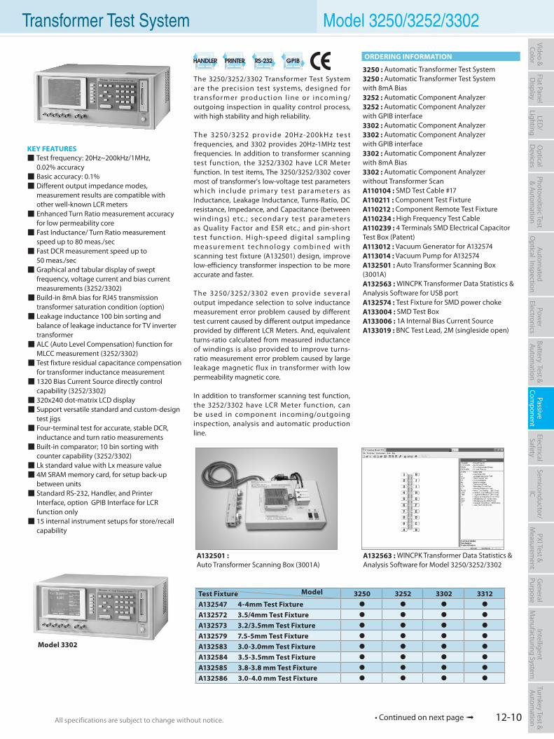
12-10All specifications are subject to change without notice. All specifications are subject to change without notice.
Flat PanelD
isplayPow
er Electronics
Electrical Safety
General
PurposePassive
Component
Semiconductor/
ICBattery Test & Autom
ationAutom
atedO
ptical Inspection Photovoltaic Test
& Automation
PXI Test &
Measurem
ent Video & Color
LED/
LightingO
ptical D
evicesIntelligent
Manufacturing System
Turnkey Test & Autom
ation
The 3250/3252/3302 Transformer Test System are the precision test systems, designed for transformer produc tion l ine or incoming/outgoing inspection in quality control process, with high stability and high reliability.
Th e 3250/3252 p rov i d e 20H z-200k H z t e s t frequencies, and 3302 provides 20Hz-1MHz test frequencies. In addition to transformer scanning test function, the 3252/3302 have LCR Meter function. In test items, The 3250/3252/3302 cover most of transformer's low-voltage test parameters which include pr imar y test parameters as Inductance, Leakage Inductance, Turns-Ratio, DC resistance, Impedance, and Capacitance (between windings) etc.; secondar y test parameters as Quality Factor and ESR etc.; and pin-short test function. High-speed digital sampling measurement technology combined with scanning test fixture (A132501) design, improve low-efficiency transformer inspection to be more accurate and faster.
The 3250/3252/3302 even provide severa l output impedance selection to solve inductance measurement error problem caused by different test current caused by different output impedance provided by different LCR Meters. And, equivalent turns-ratio calculated from measured inductance of windings is also provided to improve turns-ratio measurement error problem caused by large leakage magnetic flux in transformer with low permeability magnetic core.
In addition to transformer scanning test function, the 3252/3302 have LCR Meter function, can be used in component incoming/outgoing inspection, analysis and automatic production line.
KEY FEATURES Test frequency: 20Hz~200kHz/1MHz, 0.02% accuracy Basic accuracy: 0.1% Different output impedance modes, measurement results are compatible with other well-known LCR meters Enhanced Turn Ratio measurement accuracy for low permeability core Fast Inductance/ Turn Ratio measurement speed up to 80 meas./sec Fast DCR measurement speed up to 50 meas./sec Graphical and tabular display of swept frequency, voltage current and bias current measurements (3252/3302) Build-in 8mA bias for RJ45 transmission transformer saturation condition (option) Leakage inductance 100 bin sorting and balance of leakage inductance for TV inverter transformer ALC (Auto Level Compensation) function for MLCC measurement (3252/3302) Test fixture residual capacitance compensation for transformer inductance measurement 1320 Bias Current Source directly control capability (3252/3302) 320x240 dot-matrix LCD display Support versatile standard and custom-design test jigs Four-terminal test for accurate, stable DCR, inductance and turn ratio measurements Built-in comparator; 10 bin sorting with counter capability (3252/3302) Lk standard value with Lx measure value 4M SRAM memory card, for setup back-up between units Standard RS-232, Handler, and Printer Interface, option GPIB Interface for LCR function only 15 internal instrument setups for store/recall capability
3250 : Automatic Transformer Test System3250 : Automatic Transformer Test Systemwith 8mA Bias3252 : Automatic Component Analyzer3252 : Automatic Component Analyzerwith GPIB interface3302 : Automatic Component Analyzer3302 : Automatic Component Analyzerwith GPIB interface3302 : Automatic Component Analyzerwith 8mA Bias3302 : Automatic Component Analyzerwithout Transformer ScanA110104 : SMD Test Cable #17A110211 : Component Test FixtureA110212 : Component Remote Test FixtureA110234 : High Frequency Test CableA110239 : 4 Terminals SMD Electrical Capacitor Test Box (Patent)A113012 : Vacuum Generator for A132574A113014 : Vacuum Pump for A132574A132501 : Auto Transformer Scanning Box(3001A)A132563 : WINCPK Transformer Data Statistics & Analysis Software for USB portA132574 : Test Fixture for SMD power chokeA133004 : SMD Test BoxA133006 : 1A Internal Bias Current SourceA133019 : BNC Test Lead, 2M (singleside open)
Model 3302
A132501 : Auto Transformer Scanning Box (3001A)
Transformer Test System Model 3250/3252/3302
A132563 : WINCPK Transformer Data Statistics & Analysis Software for Model 3250/3252/3302
ORDERING INFORMATION
Test Fixture Model 3250 3252 3302 3312A132547 4-4mm Test Fixture
A132572 3.5/4mm Test Fixture
A132573 3.2/3.5mm Test Fixture
A132579 7.5-5mm Test Fixture
A132583 3.0-3.0mm Test Fixture
A132584 3.5-3.5mm Test Fixture
A132585 3.8-3.8 mm Test Fixture
A132586 3.0-4.0 mm Test Fixture
• Continued on next page
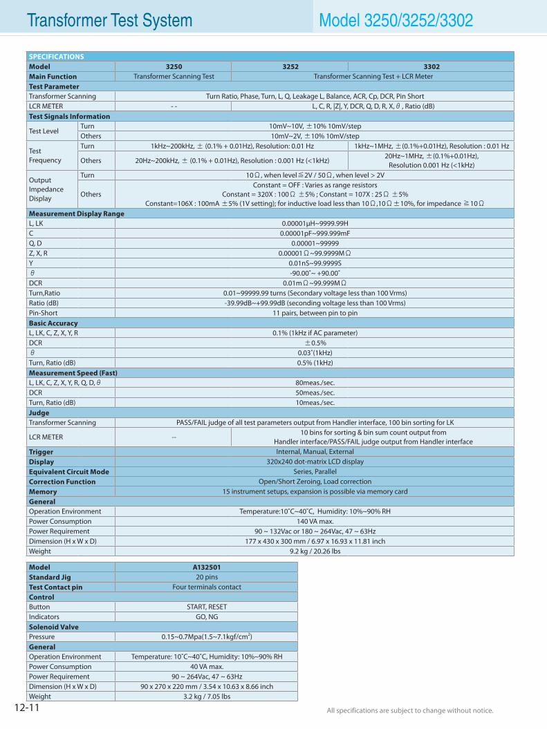
12-11 All specifications are subject to change without notice. All specifications are subject to change without notice.
Transformer Test System Model 3250/3252/3302
SPECIFICATIONSModel 3250 3252 3302Main Function Transformer Scanning Test Transformer Scanning Test + LCR MeterTest ParameterTransformer Scanning Turn Ratio, Phase, Turn, L, Q, Leakage L, Balance, ACR, Cp, DCR, Pin ShortLCR METER - - L, C, R, |Z|, Y, DCR, Q, D, R, X,θ, Ratio (dB)Test Signals Information
Test LevelTurn 10mV~10V, ±10% 10mV/stepOthers 10mV~2V, ±10% 10mV/step
TestFrequency
Turn 1kHz~200kHz, ± (0.1% + 0.01Hz), Resolution: 0.01 Hz 1kHz~1MHz, ±(0.1%+0.01Hz), Resolution : 0.01 Hz
Others 20Hz~200kHz, ± (0.1% + 0.01Hz), Resolution : 0.001 Hz (<1kHz)20Hz~1MHz, ±(0.1%+0.01Hz),
Resolution 0.001 Hz (<1kHz)
Output ImpedanceDisplay
Turn 10Ω, when level≦2V / 50Ω, when level > 2V
OthersConstant = OFF : Varies as range resistors
Constant = 320X : 100Ω ±5% ; Constant = 107X : 25Ω ±5%Constant=106X : 100mA ±5% (1V setting); for inductive load less than 10Ω,10Ω±10%, for impedance ≧10Ω
Measurement Display RangeL, LK 0.00001µH~9999.99HC 0.00001pF~999.999mFQ, D 0.00001~99999Z, X, R 0.00001Ω~99.9999MΩY 0.01nS~99.9999Sθ -90.00˚~ +90.00˚DCR 0.01mΩ~99.999MΩTurn,Ratio 0.01~99999.99 turns (Secondary voltage less than 100 Vrms)Ratio (dB) -39.99dB~+99.99dB (seconding voltage less than 100 Vrms)Pin-Short 11 pairs, between pin to pinBasic AccuracyL, LK, C, Z, X, Y, R 0.1% (1kHz if AC parameter)DCR ±0.5%θ 0.03˚(1kHz)Turn, Ratio (dB) 0.5% (1kHz)Measurement Speed (Fast)L, LK, C, Z, X, Y, R, Q, D,θ 80meas./sec.DCR 50meas./sec.Turn, Ratio (dB) 10meas./sec.JudgeTransformer Scanning PASS/FAIL judge of all test parameters output from Handler interface, 100 bin sorting for LK
LCR METER --10 bins for sorting & bin sum count output from
Handler interface/PASS/FAIL judge output from Handler interfaceTrigger Internal, Manual, ExternalDisplay 320x240 dot-matrix LCD displayEquivalent Circuit Mode Series, ParallelCorrection Function Open/Short Zeroing, Load correctionMemory 15 instrument setups, expansion is possible via memory cardGeneralOperation Environment Temperature:10˚C~40˚C, Humidity: 10%~90% RHPower Consumption 140 VA max.Power Requirement 90 ~ 132Vac or 180 ~ 264Vac, 47 ~ 63HzDimension (H x W x D) 177 x 430 x 300 mm / 6.97 x 16.93 x 11.81 inchWeight 9.2 kg / 20.26 lbs
Model A132501Standard Jig 20 pinsTest Contact pin Four terminals contactControlButton START, RESETIndicators GO, NGSolenoid ValvePressure 0.15~0.7Mpa(1.5~7.1kgf/cm2)GeneralOperation Environment Temperature: 10˚C~40˚C, Humidity: 10%~90% RHPower Consumption 40 VA max.Power Requirement 90 ~ 264Vac, 47 ~ 63HzDimension (H x W x D) 90 x 270 x 220 mm / 3.54 x 10.63 x 8.66 inchWeight 3.2 kg / 7.05 lbs
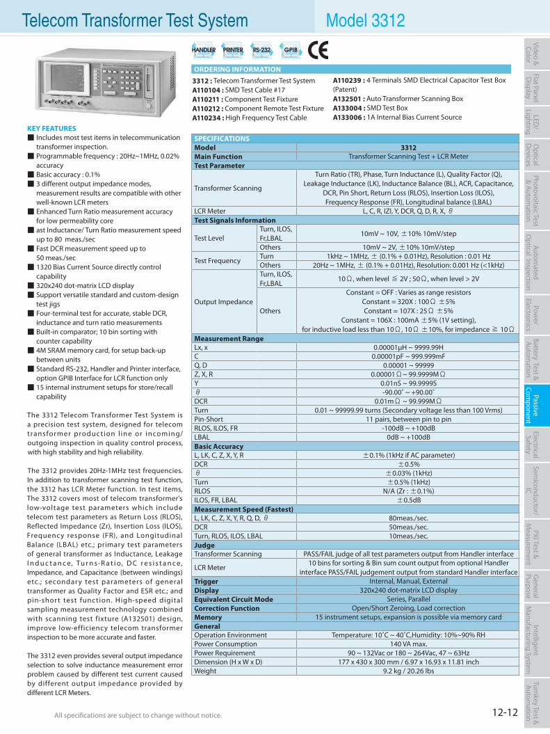
12-12All specifications are subject to change without notice. All specifications are subject to change without notice.
Flat PanelD
isplayPow
er Electronics
Electrical Safety
General
PurposePassive
Component
Semiconductor/
ICBattery Test & Autom
ationAutom
atedO
ptical Inspection Photovoltaic Test
& Automation
PXI Test &
Measurem
ent Video & Color
LED/
LightingO
ptical D
evicesIntelligent
Manufacturing System
Turnkey Test & Autom
ation
KEY FEATURES Includes most test items in telecommunication transformer inspection. Programmable frequency : 20Hz~1MHz, 0.02% accuracy Basic accuracy : 0.1% 3 different output impedance modes, measurement results are compatible with other well-known LCR meters Enhanced Turn Ratio measurement accuracy for low permeability core ast Inductance/ Turn Ratio measurement speed up to 80 meas./sec Fast DCR measurement speed up to 50 meas./sec 1320 Bias Current Source directly control capability 320x240 dot-matrix LCD display Support versatile standard and custom-design test jigs Four-terminal test for accurate, stable DCR, inductance and turn ratio measurements Built-in comparator; 10 bin sorting with counter capability 4M SRAM memory card, for setup back-up between units Standard RS-232, Handler and Printer interface, option GPIB Interface for LCR function only 15 internal instrument setups for store/recall capability
The 3312 Telecom Transformer Test System is a precision test system, designed for telecom transformer produc tion l ine or incoming/outgoing inspection in quality control process, with high stability and high reliability.
The 3312 provides 20Hz-1MHz test frequencies. In addition to transformer scanning test function, the 3312 has LCR Meter function. In test items, The 3312 covers most of telecom transformer's low-voltage test parameters which include telecom test parameters as Return Loss (RLOS), Reflected Impedance (Zr), Insertion Loss (ILOS), Frequency response (FR), and Longitudinal Balance (LBAL) etc.; primary test parameters of general transformer as Inductance, Leakage I n d u c t a n c e, Tu r n s-R a t i o, D C r e s i s t a n c e, Impedance, and Capacitance (between windings) etc.; secondar y test parameters of general transformer as Quality Factor and ESR etc.; and pin-shor t test function. High-speed digital sampling measurement technology combined with scanning test fixture (A132501) design, improve low-efficiency telecom transformer inspection to be more accurate and faster.
The 3312 even provides several output impedance selection to solve inductance measurement error problem caused by different test current caused by different output impedance provided by different LCR Meters.
3312 : Telecom Transformer Test SystemA110104 : SMD Test Cable #17A110211 : Component Test FixtureA110212 : Component Remote Test FixtureA110234 : High Frequency Test Cable
Telecom Transformer Test System Model 3312
A110239 : 4 Terminals SMD Electrical Capacitor Test Box (Patent)A132501 : Auto Transformer Scanning Box A133004 : SMD Test BoxA133006 : 1A Internal Bias Current Source
ORDERING INFORMATION
SPECIFICATIONSModel 3312Main Function Transformer Scanning Test + LCR MeterTest Parameter
Transformer Scanning
Turn Ratio (TR), Phase, Turn Inductance (L), Quality Factor (Q),Leakage Inductance (LK), Inductance Balance (BL), ACR, Capacitance,
DCR, Pin Short, Return Loss (RLOS), Insertion Loss (ILOS),Frequency Response (FR), Longitudinal balance (LBAL)
LCR Meter L, C, R, IZI, Y, DCR, Q, D, R, X, θTest Signals Information
Test LevelTurn, ILOS, Fr,LBAL
10mV ~ 10V, ±10% 10mV/step
Others 10mV ~ 2V, ±10% 10mV/step
Test FrequencyTurn 1kHz ~ 1MHz, ± (0.1% + 0.01Hz), Resolution : 0.01 HzOthers 20Hz ~ 1MHz, ± (0.1% + 0.01Hz), Resolution: 0.001 Hz (<1kHz)
Output Impedance
Turn, ILOS, Fr,LBAL
10Ω, when level ≦ 2V ; 50Ω, when level > 2V
Others
Constant = OFF : Varies as range resistorsConstant = 320X : 100Ω ±5%Constant = 107X : 25Ω ±5%
Constant = 106X : 100mA ±5% (1V setting),for inductive load less than 10Ω, 10Ω ±10%, for impedance ≧ 10Ω
Measurement RangeLx, x 0.00001µH ~ 9999.99HC 0.00001pF ~ 999.999mFQ, D 0.00001 ~ 99999Z, X, R 0.00001Ω~ 99.9999MΩY 0.01nS ~ 99.9999Sθ -90.00˚ ~ +90.00˚DCR 0.01mΩ ~ 99.999MΩTurn 0.01 ~ 99999.99 turns (Secondary voltage less than 100 Vrms)Pin-Short 11 pairs, between pin to pinRLOS, ILOS, FR -100dB ~ +100dBLBAL 0dB ~ +100dBBasic AccuracyL, LK, C, Z, X, Y, R ±0.1% (1kHz if AC parameter)DCR ±0.5%θ ±0.03% (1kHz)Turn ±0.5% (1kHz)RLOS N/A (Zr : ±0.1%)ILOS, FR, LBAL ±0.5dBMeasurement Speed (Fastest)L, LK, C, Z, X, Y, R, Q, D, θ 80meas./sec.DCR 50meas./sec.Turn, RLOS, ILOS, LBAL 10meas./sec.JudgeTransformer Scanning PASS/FAIL judge of all test parameters output from Handler interface
LCR Meter10 bins for sorting & Bin sum count output from optional Handler
interface PASS/FAIL judgement output from standard Handler interfaceTrigger Internal, Manual, ExternalDisplay 320x240 dot-matrix LCD displayEquivalent Circuit Mode Series, ParallelCorrection Function Open/Short Zeroing, Load correctionMemory 15 instrument setups, expansion is possible via memory cardGeneralOperation Environment Temperature: 10˚C ~ 40˚C,Humidity: 10%~90% RHPower Consumption 140 VA max.Power Requirement 90 ~ 132Vac or 180 ~ 264Vac, 47 ~ 63HzDimension (H x W x D) 177 x 430 x 300 mm / 6.97 x 16.93 x 11.81 inchWeight 9.2 kg / 20.26 lbs
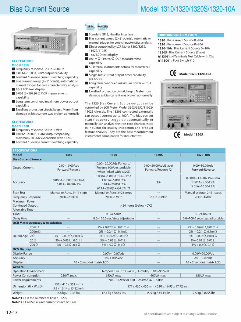
12-13 All specifications are subject to change without notice. All specifications are subject to change without notice.
Standard GPIB, Handler interface Bias current sweep (2~21points), automatic or manual trigger, for core characteristics analysis Direct controlled by LCR Meter 3302/3252/ 11022/11025 16x2 LCD text display 0.01mΩ~199.99Ω DCR measurement capability 50 internal instruments setups for store/recall capability Single bias current output timer capability (24 hours) Long term continued maximum power output capability Excellent protection circuit, keep L Meter from damage as bias current was broken abnormally
The 1320 Bias Current Source output can be controlled by LCR Meter Model 3302/3252/11022/ 11025 directly. The 1320S connected externally can output current up to 100A. The bias current scan frequency tr iggered automatical ly or manually can analyze the iron core characteristics in inductor for quality inspection and product feature analysis. They are the best measurement instruments combination for inductor test.
KEY FEATURESModel 1310 Frequency response : 20Hz~200kHz 0.001A~10.00A, 90W output capability Forward / Reverse current switching capability Bias current sweep (2~11points), automatic or manual trigger, for core characteristics analysis 16x2 LCD text display 0.001Ω~199.99Ω DCR measurement capability Long term continued maximum power output capability Excellent protection circuit, keep L Meter from damage as bias current was broken abnormally
KEY FEATURESModel 1320 Frequency response : 20Hz~1MHz 0.001A~20.00A, 150W output capability, maximum 100Adc extendable with 1320S Forward / Reverse current switching capability
1310 : Bias Current Source 0~10A1320 : Bias Current Source 0~20A1320-10A : Bias Current Source 0~10A1320S : Bias Current Source (Slave)A113011 : 4 Terminals Test Cable with ClipA115001 : Foot Switch #10
Model 1320/1320-10A
Model 1320S
Note*1 : X is the number of linked 1320SNote*2 : 1320S is a slave current source of 1320
Bias Current Source Model 1310/1320/1320S/1320-10A
ORDERING INFORMATION
SPECIFICATIONSModel 1310 1320 1320S 1320-10ABias Current Source
Output Current0.00~10.00Adc
Forward/Reverse
0.00~ 20.00Adc Forward/Reverse 100A extendablewhen linked with 1320S
0.00~20.00Adc(Slave)Forward/Reverse *2
0.00~10.00AdcForward/Reverse
Accuracy0.000A~1.000:1%+3mA
1.01A~10.00A:2%
0.000A~1.000A : 1% +3mA1.001A~5.00A:2%5.01A~20.00A:2%
20.1A~20.0(1+X)A:3% *1
3%0.000A~1.000A:1%+3mA
1.001A~5.00A:2%5.01A~10.00A:2%
Scan Test Manual or Auto, 2~11 steps Manual or Auto, 2~21 steps --- Manual or Auto, 2~21 stepsFrequency Response 20Hz~200kHz 20Hz~1MHz 20Hz~1MHz 20Hz~1MHzMaximum PowerContinued OutputAllowable Time
> 24 hours (below 40˚C)
Timer --- 0~24 hours --- 0~24 hoursDelay time --- 0.0~100.0 sec/step, adjustable --- 0.0~100.0 sec/step, adjustableDCR Meter Accuracy & Resolution
DCR Range
20mΩ --- 2% + 0.07mΩ, 0.01mΩ --- 2%+ 0.07mΩ,0.01mΩ200mΩ --- 2% + 0.2mΩ, 0.1mΩ --- 2% + 0.2mΩ,0.1mΩ2Ω 3% + 0.002Ω,0.001Ω 3% + 0.002Ω,0.001Ω --- 3%+ 0.002Ω,0.001Ω20Ω 3% + 0.03Ω, 0.01Ω 3% + 0.02Ω, 0.01Ω --- 3%+0.02Ω, 0.01Ω200Ω 3% + 0.3Ω, 0.1Ω 3% + 0.2Ω, 0.1Ω --- 3% + 0.2Ω, 0.1Ω
DCV DisplayDisplay Range --- 0.00V~10.00Vdc --- 0.00V~20.00VdcAccuracy --- 2% + 0.05Vdc --- 2% + 0.05VdcDisplay 16 x 2 text dot matrix LCD --- 16 x 2 text dot matrix LCDGeneralOperation Environment Temperature : 10˚C~40˚C, Humidity : 10%~90 % RHPower Consumption 250VA max. 650VA max. 600VA max. 650VA maxPower Requirements 90 ~ 132Vac or 180 ~ 264Vac, 47 ~ 63Hz
Dimension (H x W x D)132 x 410 x 351 mm /
5.2 x 16.14 x 13.82 inch177 x 430 x 450 mm / 6.97 x 16.93 x 17.72 inch
Weight 8.8 kg / 19.38 lbs 17.5 kg / 38.55 lbs 15.5 kg / 34.14 lbs 17.5 kg / 38.55 lbs
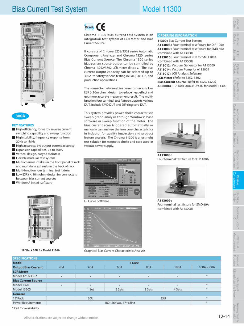
12-14All specifications are subject to change without notice. All specifications are subject to change without notice.
Flat PanelD
isplayPow
er Electronics
Electrical Safety
General
PurposePassive
Component
Semiconductor/
ICBattery Test & Autom
ationAutom
atedO
ptical Inspection Photovoltaic Test
& Automation
PXI Test &
Measurem
ent Video & Color
LED/
LightingO
ptical D
evicesIntelligent
Manufacturing System
Turnkey Test & Autom
ation
Chroma 11300 bias current test system is an integration test system of LCR Meter and Bias Current Source.
It consists of Chroma 3252/3302 series Automatic Component Analyzer and Chroma 1320 series Bias Current Source. The Chroma 1320 series bias current source output can be controlled by Chroma 3252/3302 LCR meter directly. The bias current output capacity can be selected up to 300A to satisfy various testing in R&D, QC, QA, and production applications.
The connector between bias current sources is low ESR (<10m ohm ) design to reduce heat effect and get more accurate measurement result. The multi-function four terminal test fixture supports various DUT, include SMD DUT and DIP ring core DUT.
This system provides power choke characteristic sweep graph analysis through Windows® base software or sweep function of the meter. The bias current scan triggered automatically or manually can analyze the iron core characteristics in inductor for quality inspection and product feature analysis. The Chroma 11300 is a just right test solution for magnetic choke and core used in various power supply.
KEY FEATURES High efficiency, forward / reverse current
switching capability and sweep function High stability, frequency response from 20Hz to 1MHz High accuracy, 3% output current accuracy Expansion capabilities, up to 300A Vertical design, easy to maintain Flexible modular test system Multi-channel intakes in the front panel of rack
and multi-fans exhausts in the back of rack Multi-function four terminal test fixture Low ESR ( < 10m ohm) design for connecters
between bias current sources Windows® based software
11300 : Bias Current Test SystemA113008 : Four terminal test fixture for DIP 100AA113009 : Four terminal test fixture for SMD 60A (combined with A113008)A113010 : Four terminal PCB for SMD 100A(combined with A113008)A113012 : Vacuum Generator for A113009A113014 : Vacuum Pump for A113009A113017 : LCR Analysis SoftwareLCR Meter : Refer to 3252, 3302Bias Current Source : Refer to 1320, 1320SA800004 : 19" rack 20U/35U/41U for Model 11300
L-I Curve Software
*Please refer to respective product catalogs for detail specifications
19" Rack 20U for Model 11300 Graphical Bias Current Characteristic Analysis
A113009 :Four terminal test fixture for SMD 60A (combined with A113008)
A113008 :Four terminal test fixture for DIP 100A
Bias Current Test System Model 11300
SPECIFICATIONSModel 11300Output Bias Current 20A 40A 60A 80A 100A 100A~300ALCR MeterModel 3252/3302 • • • • • *Bias Current SourceModel 1320 • • • • • *Model 1320S 1 Set 2 Sets 3 Sets 4 Sets *General19"Rack 20U 35U *Power Requirements 180~264Vac, 47~63Hz *
Model 1310/1320/1320S/1320-10A
ORDERING INFORMATION
* Call for availability
300A
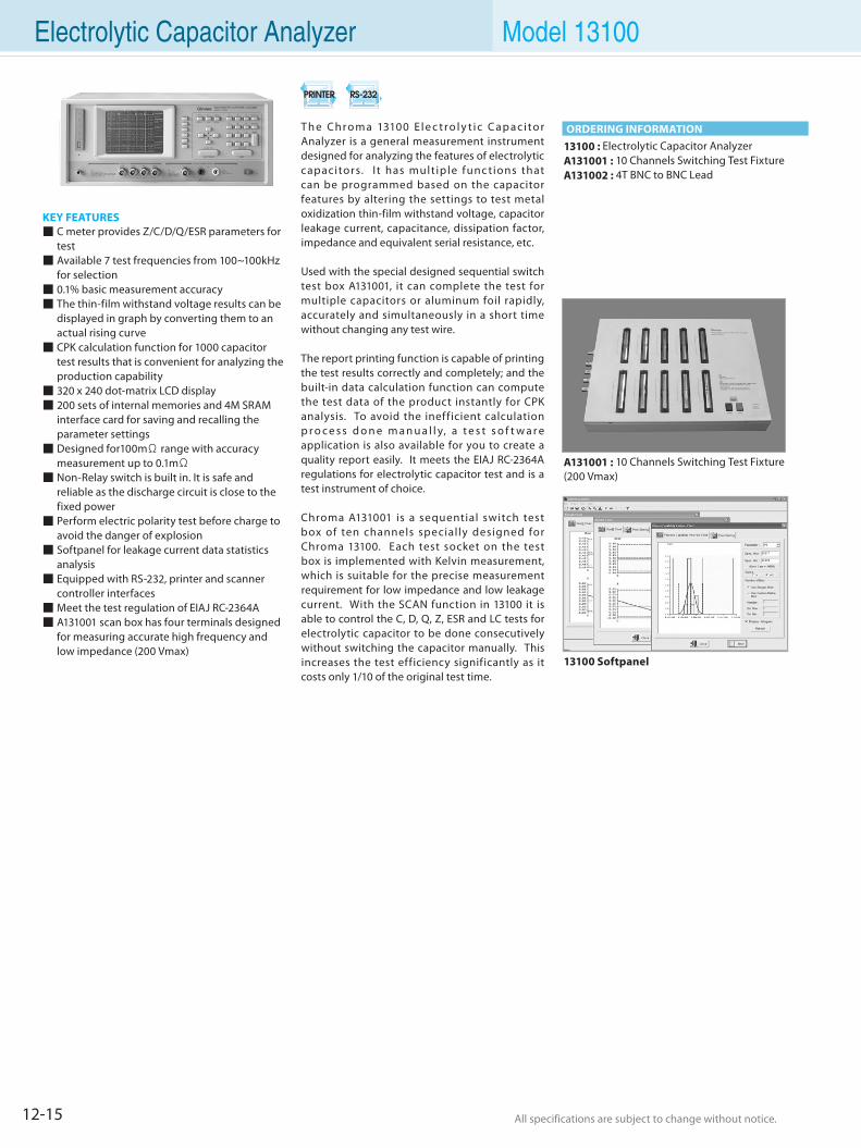
12-15 All specifications are subject to change without notice. All specifications are subject to change without notice.
KEY FEATURES C meter provides Z/C/D/Q/ESR parameters for
test Available 7 test frequencies from 100~100kHz
for selection 0.1% basic measurement accuracy The thin-film withstand voltage results can be
displayed in graph by converting them to an actual rising curve
CPK calculation function for 1000 capacitor test results that is convenient for analyzing the production capability
320 x 240 dot-matrix LCD display 200 sets of internal memories and 4M SRAM
interface card for saving and recalling the parameter settings
Designed for100mΩ range with accuracy measurement up to 0.1mΩ
Non-Relay switch is built in. It is safe and reliable as the discharge circuit is close to the fixed power
Perform electric polarity test before charge to avoid the danger of explosion
Softpanel for leakage current data statistics analysis
Equipped with RS-232, printer and scanner controller interfaces
Meet the test regulation of EIAJ RC-2364A A131001 scan box has four terminals designed
for measuring accurate high frequency and low impedance (200 Vmax)
Electrolytic Capacitor Analyzer Model 13100
A131001 : 10 Channels Switching Test Fixture(200 Vmax)
13100 Softpanel
13100 : Electrolytic Capacitor AnalyzerA131001 : 10 Channels Switching Test FixtureA131002 : 4T BNC to BNC Lead
ORDERING INFORMATIONT h e Ch r o m a 13100 E l e c t r o l y t i c C a p a c i to r Analyzer is a general measurement instrument designed for analyzing the features of electrolytic capacitors. I t has mult iple func tions that can be programmed based on the capacitor features by altering the settings to test metal oxidization thin-film withstand voltage, capacitor leakage current, capacitance, dissipation factor, impedance and equivalent serial resistance, etc.
Used with the special designed sequential switch test box A131001, it can complete the test for multiple capacitors or aluminum foil rapidly, accurately and simultaneously in a short time without changing any test wire.
The report printing function is capable of printing the test results correctly and completely; and the built-in data calculation function can compute the test data of the product instantly for CPK analysis. To avoid the inefficient calculation p r o c e s s d o n e m a n u a l l y, a t e s t s o f t w a r e application is also available for you to create a quality report easily. It meets the EIAJ RC-2364A regulations for electrolytic capacitor test and is a test instrument of choice.
Chroma A131001 is a sequential switch test box of ten channels specially designed for Chroma 13100. Each test socket on the test box is implemented with Kelvin measurement, which is suitable for the precise measurement requirement for low impedance and low leakage current. With the SCAN function in 13100 it is able to control the C, D, Q, Z, ESR and LC tests for electrolytic capacitor to be done consecutively without switching the capacitor manually. This increases the test efficiency significantly as it costs only 1/10 of the original test time.
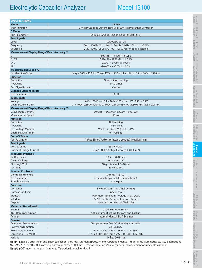
12-16All specifications are subject to change without notice. All specifications are subject to change without notice.
Flat PanelD
isplayPow
er Electronics
Electrical Safety
General
PurposePassive
Component
Semiconductor/
ICBattery Test & Autom
ationAutom
atedO
ptical Inspection Photovoltaic Test
& Automation
PXI Test &
Measurem
ent Video & Color
LED/
LightingO
ptical D
evicesIntelligent
Manufacturing System
Turnkey Test & Autom
ation Electrolytic Capacitor Analyzer Model 13100
Note*1 : 23±5˚C after Open and Short correction, slow measurement speed, refer to Operation Manual for detail measurement accuracy descriptionsNote*2 : 23±5˚C after Null correction, average exceeds 10 times, refer to Operation Manual for detail measurement accuracy descriptionsNote*3 : C/D meter in range >1Ω, refer to Operation Manual for detail
SPECIFICATIONSModel 13100Main Function C Meter/Leakage Current Tester/Foil WV Tester/Scanner ControllerC MeterTest Parameter Cs-D, Cs-Q, Cs-ESR, Cp-D, Cp-Q, |Z|-ESR, |Z|-θTest SignalsLevel 1.0V/0.25V, ±10%Frequency 100Hz, 120Hz, 1kHz, 10kHz, 20kHz, 50kHz, 100kHz; ±0.01%Source Ro 25Ω, 100Ω, 25Ω/C.C, 100Ω/25Ω four mode selectableMeasurement Display Range/ Basic Accuracy *1C 0.001pF ~ 1.9999F / ±0.1%Z, ESR 0.01mΩ~ 99.99MΩ/ ±0.1%D, Q 0.0001 ~ 9999 / ±0.0005θ -90.00˚ ~ +90.00˚ / ±0.03˚Measurement Speed *2Fast/Medium/Slow Freq. = 100Hz 120Hz : 55ms / 120ms/ 750ms; Freq 1kHz : 35ms / 60ms / 370msFunctionCorrection Open / Short zeroingAveraging 1~99 timesTest Signal Monitor Vm, ImLeakage Current TesterTest Parameter LC, IRTest SignalsVoltage 1.0 V ~ 100 V, step 0.1 V;101V~650 V, step 1V; (0.5% + 0.2V)Charge Current Limit V ≦ 100V: 0.5mA~500mA; V>100V: 0.5mA~150mA; step 0.5mA; (3% + 0.05mA)Measurement Display Range/ Basic Accuracy *3LC (Leakage Current) 0.001µA ~ 99.9mA/ ±(0.3% +0.005µA)Measurement Speed 45msFunctionCorrection Null zeroingAveraging 1 ~ 99 timesTest Voltage Monitor Vm: 0.0 V ~ 660.0V; (0.2%+0.1V)Charge/ Dwell Timer 0 ~ 999 sec.Foil WV TesterTest Parameter Tr (Rise Time), Vt (Foil Withstand Voltage), Plot [logT, Vm]Test SignalsVoltage Limit 650 V typicalConstant Charge Current 0.5mA~100mA, step 0.5mA; (3% +0.05mA)Test Display RangeTr (Rise Time) 0.05 ~ 120.00 sec.Charge Voltage 0.1V ~ 660.0VPlot [logT, Vm] 220 plots; Vm: 1.5~10 x VfTest Time 30 ~ 600 sec.Scanner ControllerControllable Fixture Chroma A131001Test Parameter C parameter pair x 2, LC parameter x 1Sample Number 1~1000 pcs.FunctionCorrection Fixture Open/ Short/ Null zeroingComparison Limit Upper, LowerStatistics Maximum, Minimum, Average (X bar), CpkInterface RS-232, Printer, Scanner Control InterfaceDisplay 320 x 240 dot-matrix LCD displayMemory (Store/Recall)Internal 200 instrument setups4M SRAM card (Option) 200 instrument setups (for copy and backup)Trigger Internal, Manual, BUS, ScannerGeneralOperation Environment Temperature 0˚C~40˚C, Humidity < 90 % RHPower Consumption 400 VA max.Power Requirement 90 ~ 132Vac or 180 ~ 264Vac, 47 ~ 63HzDimension (H x W x D) 177 x 430 x 301.4 mm / 6.97 x 16.93 x 11.87 inchWeight 14 kg / 30.84 lbs
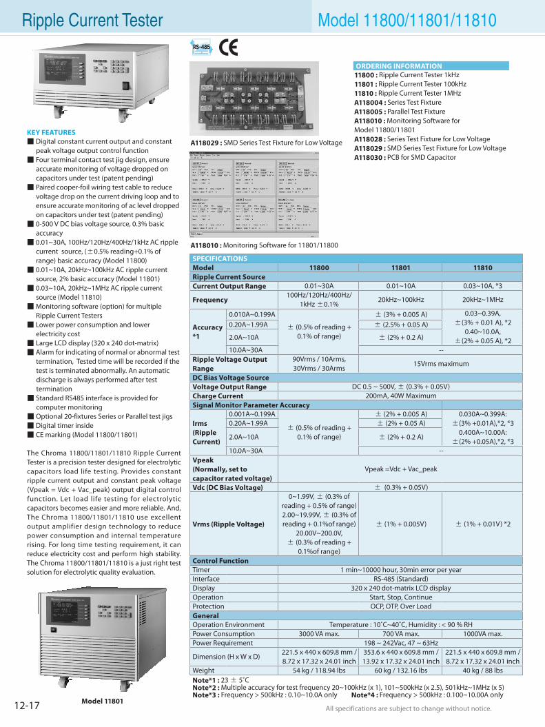
12-17 All specifications are subject to change without notice. All specifications are subject to change without notice.
Ripple Current Tester Model 11800/11801/11810
KEY FEATURES Digital constant current output and constant peak voltage output control function Four terminal contact test jig design, ensure accurate monitoring of voltage dropped on capacitors under test (patent pending) Paired cooper-foil wiring test cable to reduce voltage drop on the current driving loop and to ensure accurate monitoring of ac level dropped on capacitors under test (patent pending) 0-500 V DC bias voltage source, 0.3% basic accuracy 0.01~30A, 100Hz/120Hz/400Hz/1kHz AC ripple current source, (±0.5% reading+0.1% of range) basic accuracy (Model 11800) 0.01~10A, 20kHz~100kHz AC ripple current source, 2% basic accuracy (Model 11801) 0.03~10A, 20kHz~1MHz AC ripple current source (Model 11810) Monitoring software (option) for multiple Ripple Current Testers Lower power consumption and lower electricity cost Large LCD display (320 x 240 dot-matrix) Alarm for indicating of normal or abnormal test termination, Tested time will be recorded if the test is terminated abnormally. An automatic discharge is always performed after test termination Standard RS485 interface is provided for computer monitoring Optional 20-fixtures Series or Parallel test jigs Digital timer inside CE marking (Model 11800/11801)
The Chroma 11800/11801/11810 Ripple Current Tester is a precision tester designed for electrolytic capacitors load life testing. Provides constant ripple current output and constant peak voltage (Vpeak = Vdc + Vac_peak) output digital control function. Let load life testing for electrolytic capacitors becomes easier and more reliable. And, The Chroma 11800/11801/11810 use excellent output amplifier design technology to reduce power consumption and internal temperature rising. For long time testing requirement, it can reduce electricity cost and perform high stability. The Chroma 11800/11801/11810 is a just right test solution for electrolytic quality evaluation.
11800 : Ripple Current Tester 1kHz11801 : Ripple Current Tester 100kHz11810 : Ripple Current Tester 1MHzA118004 : Series Test FixtureA118005 : Parallel Test FixtureA118010 : Monitoring Software forModel 11800/11801A118028 : Series Test Fixture for Low VoltageA118029 : SMD Series Test Fixture for Low Voltage A118030 : PCB for SMD Capacitor
Model 11801
A118010 : Monitoring Software for 11801/11800
ORDERING INFORMATION
A118029 : SMD Series Test Fixture for Low Voltage
SPECIFICATIONSModel 11800 11801 11810Ripple Current SourceCurrent Output Range 0.01~30A 0.01~10A 0.03~10A, *3
Frequency100Hz/120Hz/400Hz/
1kHz ±0.1%20kHz~100kHz 20kHz~1MHz
Accuracy*1
0.010A~0.199A
± (0.5% of reading + 0.1% of range)
± (3% + 0.005 A) 0.03~0.39A, ±(3% + 0.01 A), *2
0.40~10.0A, ±(2% + 0.05 A), *2
0.20A~1.99A ± (2.5% + 0.05 A)
2.0A~10A ± (2% + 0.2 A)
10.0A~30A --Ripple Voltage Output Range
90Vrms / 10Arms, 30Vrms / 30Arms
15Vrms maximum
DC Bias Voltage SourceVoltage Output Range DC 0.5 ~ 500V, ± (0.3% + 0.05V)Charge Current 200mA, 40W MaximumSignal Monitor Parameter Accuracy
Irms (RippleCurrent)
0.001A~0.199A
± (0.5% of reading + 0.1% of range)
± (2% + 0.005 A) 0.030A~0.399A: ±(3% +0.01A),*2, *3
0.400A~10.00A: ±(2% +0.05A),*2, *3
0.20A~1.99A ± (2% + 0.05 A)
2.0A~10A ± (2% + 0.2 A)
10.0A~30A --Vpeak (Normally, set to capacitor rated voltage)
Vpeak =Vdc + Vac_peak
Vdc (DC Bias Voltage) ± (0.3% + 0.05V)
Vrms (Ripple Voltage)
0~1.99V, ± (0.3% of reading + 0.5% of range)2.00~19.99V, ± (0.3% of reading + 0.1%of range)
20.00V~200.0V, ± (0.3% of reading +
0.1%of range)
± (1% + 0.005V) ± (1% + 0.01V) *2
Control FunctionTimer 1 min~10000 hour, 30min error per yearInterface RS-485 (Standard)Display 320 x 240 dot-matrix LCD displayOperation Start, Stop, ContinueProtection OCP, OTP, Over LoadGeneralOperation Environment Temperature : 10˚C~40˚C, Humidity : < 90 % RHPower Consumption 3000 VA max. 700 VA max. 1000VA max.Power Requirement 198 ~ 242Vac, 47 ~ 63Hz
Dimension (H x W x D)221.5 x 440 x 609.8 mm /8.72 x 17.32 x 24.01 inch
353.6 x 440 x 609.8 mm /13.92 x 17.32 x 24.01 inch
221.5 x 440 x 609.8 mm /8.72 x 17.32 x 24.01 inch
Weight 54 kg / 118.94 lbs 60 kg / 132.16 lbs 40 kg / 88 lbsNote*1 : 23 ± 5˚CNote*2 : Multiple accuracy for test frequency 20~100kHz (x 1), 101~500kHz (x 2.5), 501kHz~1MHz (x 5)Note*3 : Frequency > 500kHz : 0.10~10.0A only Note*4 : Frequency > 500kHz : 0.100~10.00A only
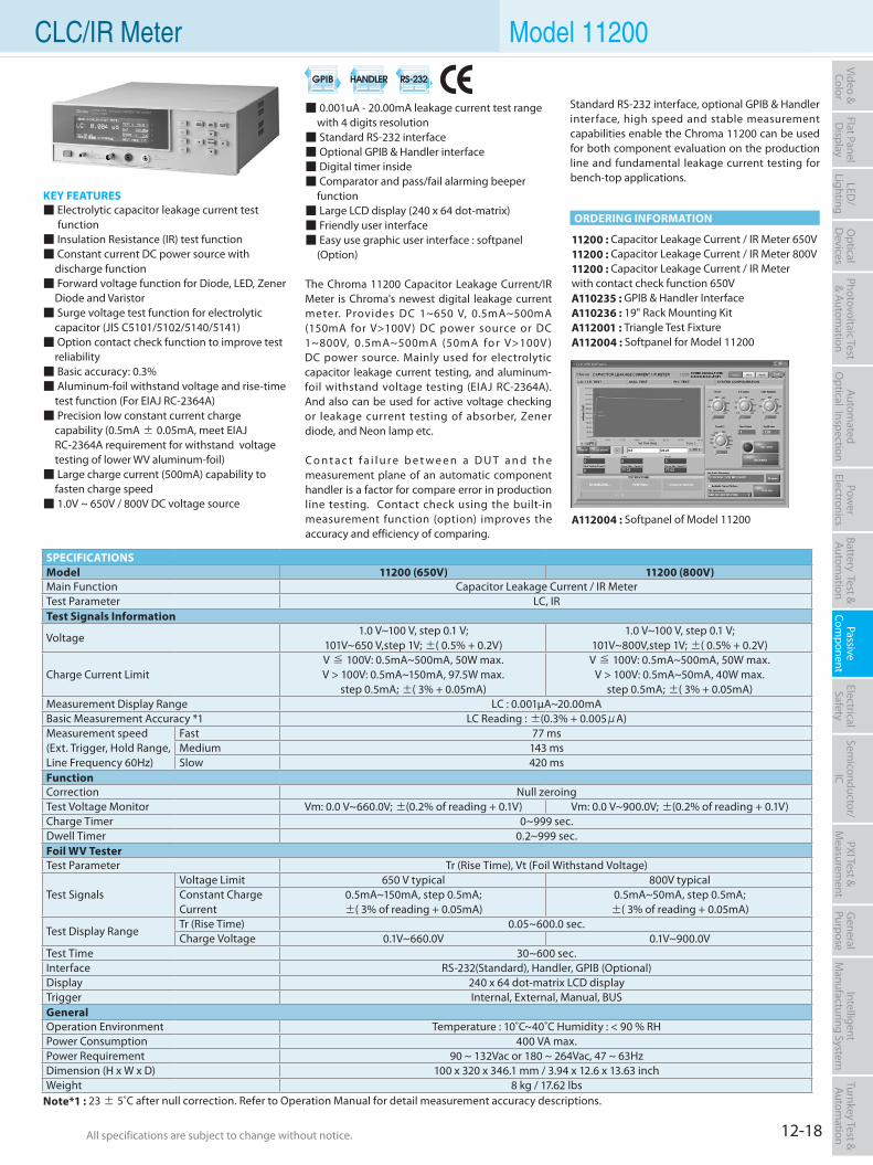
12-18All specifications are subject to change without notice. All specifications are subject to change without notice.
Flat PanelD
isplayPow
er Electronics
Electrical Safety
General
PurposePassive
Component
Semiconductor/
ICBattery Test & Autom
ationAutom
atedO
ptical Inspection Photovoltaic Test
& Automation
PXI Test &
Measurem
ent Video & Color
LED/
LightingO
ptical D
evicesIntelligent
Manufacturing System
Turnkey Test & Autom
ation CLC/IR Meter Model 11200
KEY FEATURES Electrolytic capacitor leakage current test function Insulation Resistance (IR) test function Constant current DC power source with discharge function Forward voltage function for Diode, LED, Zener Diode and Varistor Surge voltage test function for electrolytic capacitor (JIS C5101/5102/5140/5141) Option contact check function to improve test reliability Basic accuracy: 0.3% Aluminum-foil withstand voltage and rise-time test function (For EIAJ RC-2364A) Precision low constant current charge capability (0.5mA ± 0.05mA, meet EIAJ RC-2364A requirement for withstand voltage testing of lower WV aluminum-foil) Large charge current (500mA) capability to fasten charge speed 1.0V ~ 650V / 800V DC voltage source
11200 : Capacitor Leakage Current / IR Meter 650V11200 : Capacitor Leakage Current / IR Meter 800V11200 : Capacitor Leakage Current / IR Meter with contact check function 650VA110235 : GPIB & Handler InterfaceA110236 : 19" Rack Mounting KitA112001 : Triangle Test FixtureA112004 : Softpanel for Model 11200
0.001uA - 20.00mA leakage current test range with 4 digits resolution Standard RS-232 interface Optional GPIB & Handler interface Digital timer inside Comparator and pass/fail alarming beeper function Large LCD display (240 x 64 dot-matrix) Friendly user interface Easy use graphic user interface : softpanel (Option)
The Chroma 11200 Capacitor Leakage Current/IR Meter is Chroma's newest digital leakage current meter. Provides DC 1~650 V, 0.5mA~500mA (150mA for V>100V) DC power source or DC 1~800V, 0.5mA~500mA (50mA for V>100V ) DC power source. Mainly used for electrolytic capacitor leakage current testing, and aluminum-foil withstand voltage testing (EIAJ RC-2364A). And also can be used for active voltage checking or leakage current testing of absorber, Zener diode, and Neon lamp etc.
C o n t a c t f a i l u r e b e t w e e n a D U T a n d t h e measurement plane of an automatic component handler is a factor for compare error in production line testing. Contact check using the built-in measurement function (option) improves the accuracy and efficiency of comparing.
A112004 : Softpanel of Model 11200
Note*1 : 23 ± 5˚C after null correction. Refer to Operation Manual for detail measurement accuracy descriptions.
ORDERING INFORMATION
Standard RS-232 interface, optional GPIB & Handler interface, high speed and stable measurement capabilities enable the Chroma 11200 can be used for both component evaluation on the production line and fundamental leakage current testing for bench-top applications.
SPECIFICATIONSModel 11200 (650V) 11200 (800V)Main Function Capacitor Leakage Current / IR MeterTest Parameter LC, IRTest Signals Information
Voltage1.0 V~100 V, step 0.1 V;
101V~650 V,step 1V; ±( 0.5% + 0.2V)1.0 V~100 V, step 0.1 V;
101V~800V,step 1V; ±( 0.5% + 0.2V)
Charge Current LimitV ≦ 100V: 0.5mA~500mA, 50W max.V > 100V: 0.5mA~150mA, 97.5W max.
step 0.5mA; ±( 3% + 0.05mA)
V ≦ 100V: 0.5mA~500mA, 50W max.V > 100V: 0.5mA~50mA, 40W max.
step 0.5mA; ±( 3% + 0.05mA)Measurement Display Range LC : 0.001µA~20.00mABasic Measurement Accuracy *1 LC Reading : ±(0.3% + 0.005μA)Measurement speed (Ext. Trigger, Hold Range, Line Frequency 60Hz)
Fast 77 msMedium 143 msSlow 420 ms
FunctionCorrection Null zeroingTest Voltage Monitor Vm: 0.0 V~660.0V; ±(0.2% of reading + 0.1V) Vm: 0.0 V~900.0V; ±(0.2% of reading + 0.1V)Charge Timer 0~999 sec.Dwell Timer 0.2~999 sec.Foil WV TesterTest Parameter Tr (Rise Time), Vt (Foil Withstand Voltage)
Test SignalsVoltage Limit 650 V typical 800V typicalConstant Charge Current
0.5mA~150mA, step 0.5mA; ±( 3% of reading + 0.05mA)
0.5mA~50mA, step 0.5mA; ±( 3% of reading + 0.05mA)
Test Display RangeTr (Rise Time) 0.05~600.0 sec.Charge Voltage 0.1V~660.0V 0.1V~900.0V
Test Time 30~600 sec.Interface RS-232(Standard), Handler, GPIB (Optional)Display 240 x 64 dot-matrix LCD displayTrigger Internal, External, Manual, BUSGeneralOperation Environment Temperature : 10˚C~40˚C Humidity : < 90 % RHPower Consumption 400 VA max.Power Requirement 90 ~ 132Vac or 180 ~ 264Vac, 47 ~ 63HzDimension (H x W x D) 100 x 320 x 346.1 mm / 3.94 x 12.6 x 13.63 inchWeight 8 kg / 17.62 lbs
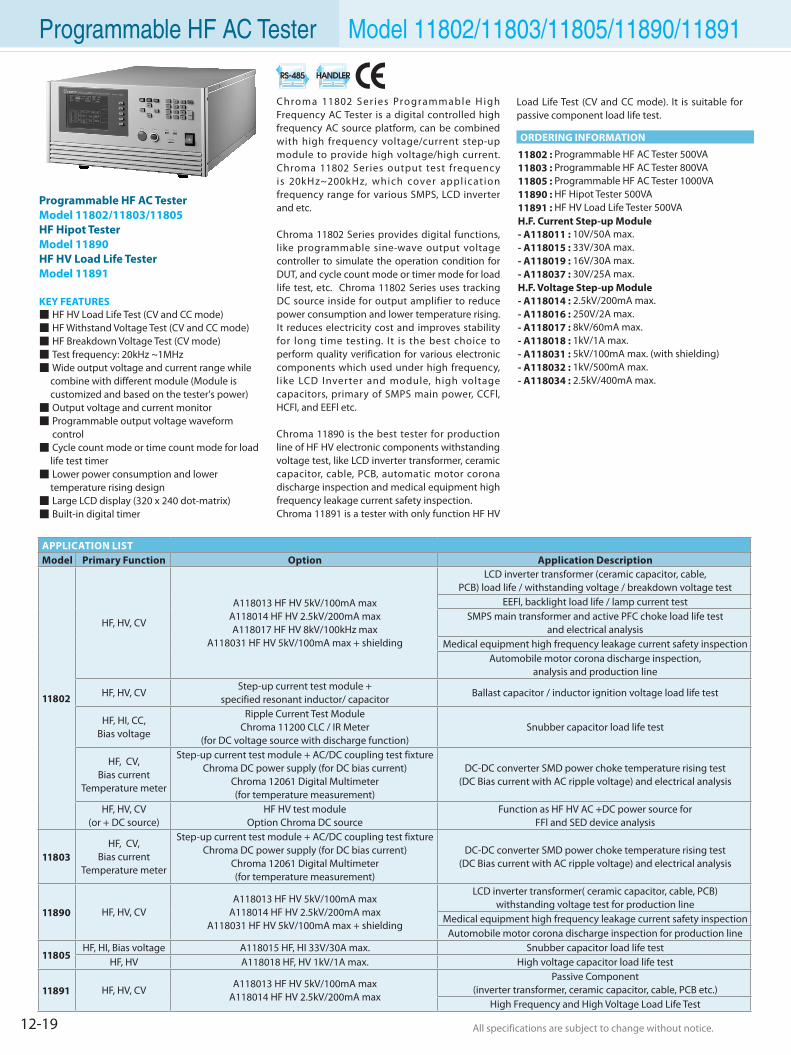
12-19 All specifications are subject to change without notice. All specifications are subject to change without notice.
Programmable HF AC Tester Model 11802/11803/11805/11890/11891
11802 : Programmable HF AC Tester 500VA11803 : Programmable HF AC Tester 800VA11805 : Programmable HF AC Tester 1000VA11890 : HF Hipot Tester 500VA11891 : HF HV Load Life Tester 500VAH.F. Current Step-up Module- A118011 : 10V/50A max.- A118015 : 33V/30A max.- A118019 : 16V/30A max.- A118037 : 30V/25A max. H.F. Voltage Step-up Module- A118014 : 2.5kV/200mA max.- A118016 : 250V/2A max.- A118017 : 8kV/60mA max.- A118018 : 1kV/1A max. - A118031 : 5kV/100mA max. (with shielding) - A118032 : 1kV/500mA max.- A118034 : 2.5kV/400mA max.
ORDERING INFORMATION
Programmable HF AC TesterModel 11802/11803/11805HF Hipot TesterModel 11890HF HV Load Life TesterModel 11891
KEY FEATURES HF HV Load Life Test (CV and CC mode) HF Withstand Voltage Test (CV and CC mode) HF Breakdown Voltage Test (CV mode) Test frequency: 20kHz ~1MHz Wide output voltage and current range while combine with different module (Module is customized and based on the tester's power) Output voltage and current monitor Programmable output voltage waveform control Cycle count mode or time count mode for load life test timer Lower power consumption and lower temperature rising design Large LCD display (320 x 240 dot-matrix) Built-in digital timer
Chroma 11802 Ser ies Programmable H igh Frequency AC Tester is a digital controlled high frequency AC source platform, can be combined with high frequency voltage/current step-up module to provide high voltage/high current. Chroma 11802 Series output test frequency is 20kHz~200kHz, which cover appl icat ion frequency range for various SMPS, LCD inverter and etc.
Chroma 11802 Series provides digital functions, like programmable sine-wave output voltage controller to simulate the operation condition for DUT, and cycle count mode or timer mode for load life test, etc. Chroma 11802 Series uses tracking DC source inside for output amplifier to reduce power consumption and lower temperature rising. It reduces electricity cost and improves stability for long time testing. It is the best choice to perform quality verification for various electronic components which used under high frequency, l ike LCD Inverter and module, high voltage capacitors, primary of SMPS main power, CCFl, HCFl, and EEFl etc.
Chroma 11890 is the best tester for production line of HF HV electronic components withstanding voltage test, like LCD inverter transformer, ceramic capacitor, cable, PCB, automatic motor corona discharge inspection and medical equipment high frequency leakage current safety inspection.Chroma 11891 is a tester with only function HF HV
APPLICATION LISTModel Primary Function Option Application Description
11802
HF, HV, CV
A118013 HF HV 5kV/100mA maxA118014 HF HV 2.5kV/200mA maxA118017 HF HV 8kV/100kHz max
A118031 HF HV 5kV/100mA max + shielding
LCD inverter transformer (ceramic capacitor, cable, PCB) load life / withstanding voltage / breakdown voltage test
EEFl, backlight load life / lamp current testSMPS main transformer and active PFC choke load life test
and electrical analysisMedical equipment high frequency leakage current safety inspection
Automobile motor corona discharge inspection, analysis and production line
HF, HV, CVStep-up current test module +
specified resonant inductor/ capacitorBallast capacitor / inductor ignition voltage load life test
HF, HI, CC,Bias voltage
Ripple Current Test ModuleChroma 11200 CLC / IR Meter
(for DC voltage source with discharge function)Snubber capacitor load life test
HF, CV,Bias current
Temperature meter
Step-up current test module + AC/DC coupling test fixture Chroma DC power supply (for DC bias current)
Chroma 12061 Digital Multimeter(for temperature measurement)
DC-DC converter SMD power choke temperature rising test (DC Bias current with AC ripple voltage) and electrical analysis
HF, HV, CV(or + DC source)
HF HV test moduleOption Chroma DC source
Function as HF HV AC +DC power source forFFl and SED device analysis
11803HF, CV,
Bias currentTemperature meter
Step-up current test module + AC/DC coupling test fixture Chroma DC power supply (for DC bias current)
Chroma 12061 Digital Multimeter(for temperature measurement)
DC-DC converter SMD power choke temperature rising test (DC Bias current with AC ripple voltage) and electrical analysis
11890 HF, HV, CVA118013 HF HV 5kV/100mA max
A118014 HF HV 2.5kV/200mA maxA118031 HF HV 5kV/100mA max + shielding
LCD inverter transformer( ceramic capacitor, cable, PCB) withstanding voltage test for production line
Medical equipment high frequency leakage current safety inspectionAutomobile motor corona discharge inspection for production line
11805HF, HI, Bias voltage A118015 HF, HI 33V/30A max. Snubber capacitor load life test
HF, HV A118018 HF, HV 1kV/1A max. High voltage capacitor load life test
11891 HF, HV, CVA118013 HF HV 5kV/100mA max
A118014 HF HV 2.5kV/200mA max
Passive Component(inverter transformer, ceramic capacitor, cable, PCB etc.)
High Frequency and High Voltage Load Life Test
Load Life Test (CV and CC mode). It is suitable for passive component load life test.
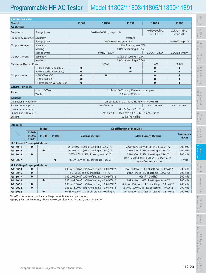
12-20All specifications are subject to change without notice. All specifications are subject to change without notice.
Flat PanelD
isplayPow
er Electronics
Electrical Safety
General
PurposePassive
Component
Semiconductor/
ICBattery Test & Autom
ationAutom
atedO
ptical Inspection Photovoltaic Test
& Automation
PXI Test &
Measurem
ent Video & Color
LED/
LightingO
ptical D
evicesIntelligent
Manufacturing System
Turnkey Test & Autom
ation Programmable HF AC Tester Model 11802/11803/11805/11890/11891
SPECIFICATIONSModel 11802 11890 11891 11805 11803AC Output
Frequency Range (rms) 20kHz~200kHz, step 1kHz10kHz~200kHz,
step 1kHz20kHz~1MHz,
step 1kHzFrequency accuracy accuracy ±0.02%
Output Voltage Range (rms) 165V maximum, step 1 V 1~143V, step 1 Vaccuracy ±(5% of setting + 0. 5V)reading ±(4% of reading + 0. 5V)
Output Current Range (rms) 0.01A ~ 3.10A 0.05A ~ 6.20A 5.6A maximumaccuracy ±(5% of setting + 0.5A) reading ±(4% of reading + 0.5A)
Maximum Output Power 500VA 1kVA 800VA
Output mode
HF HV Load Life Test (CV)
HF HV Load Life Test (CC)
HF WV Test (CV)
HF WV Test (CC)
HF Breakdown Voltage Test
Control Function
TimerLoad Life Test 1 min ~ 10000 hour, 30min error per yearWV Test 0.1 sec ~ 999.9 sec
GeneralOperation Environment Temperature : 10˚C~ 40˚C, Humidity : < 90% RHPower Consumption 2700 VA max. 3000 VA max. 2700 VA max.Power Requirement 198 ~ 242Vac, 47 ~ 63HzDimension (H x W x D) 241.5 x 440 x 609.8 mm / 8.72 x 17.32 x 24.01 inchWeight 32 kg /70.48 lbs
ModulesTester Specification of Modules
11802/11890/11891
11805 11803 Voltage Output Max. Current OutputFrequency
(kHz)
H.F. Current Step-up ModulesA118011 0.1V~10V, ±(5% of setting + 0.05V) *2 2.5A~50A, ±(4% of setting + 0.05A) *2 200 kHzA118015 0.5V~33V, ±(5% of setting + 0.15V) *2 0.2A~30A, ±(4% of setting + 0.1A) *2 200 kHzA118019 0.2V~16V, ±(5% of setting + 0.1V) *2 0.2A~30A, ±(4% of setting + 0.1A) *2 200 kHz
A118037 0.50V~30V, ±(4% of reading + 0.3V)0.5A~25.0A (500kHz), 0.5A~15.0A (1MHz),
±(3% of setting + 0.2A)1 MHz
H.F. Voltage Step-up ModulesA118014 0.05kV~2.50kV, ±(5% of setting + 0.01kV) *2 1mA~200mA, ±(4% of setting + 0.3mA) *2 200 kHzA118016 5V~250V, ±(5% of setting + 1V) *2 0.01A~2A, ±(4% of setting + 5mA) *2 200 kHzA118017 0.05kV~8.00kV, ±(5% of setting + 0.02kV) *2 60mA (100kHz) 200 kHzA118018 0.05kV~1.00kV, ±(5% of setting + 0.01kV) *2 0.01A~1A, ±(4% of setting + 3mA) *2 200 kHzA118031 0.05kV~5.00kV, ±(5% of setting + 0.01kV) *2 0.5mA~100mA, ±(4% of setting + 0.3mA) *2 200 kHzA118032 0.05kV~1.00kV, ±(5% of setting + 0.01kV) *2 2.5mA~500mA, ±(4% of setting + 1mA) *2 200 kHzA118034 0.01kV~2.5kV, ±(5% of setting + 0.01kV) *2 1.5mA~400mA, ±(4% of setting + 0.2mA) *2 200 kHz
Note*1 : Under rated load and voltage correction is well performedNote*2 : For test frequency above 100kHz, multiply the accuracy error by 2 times
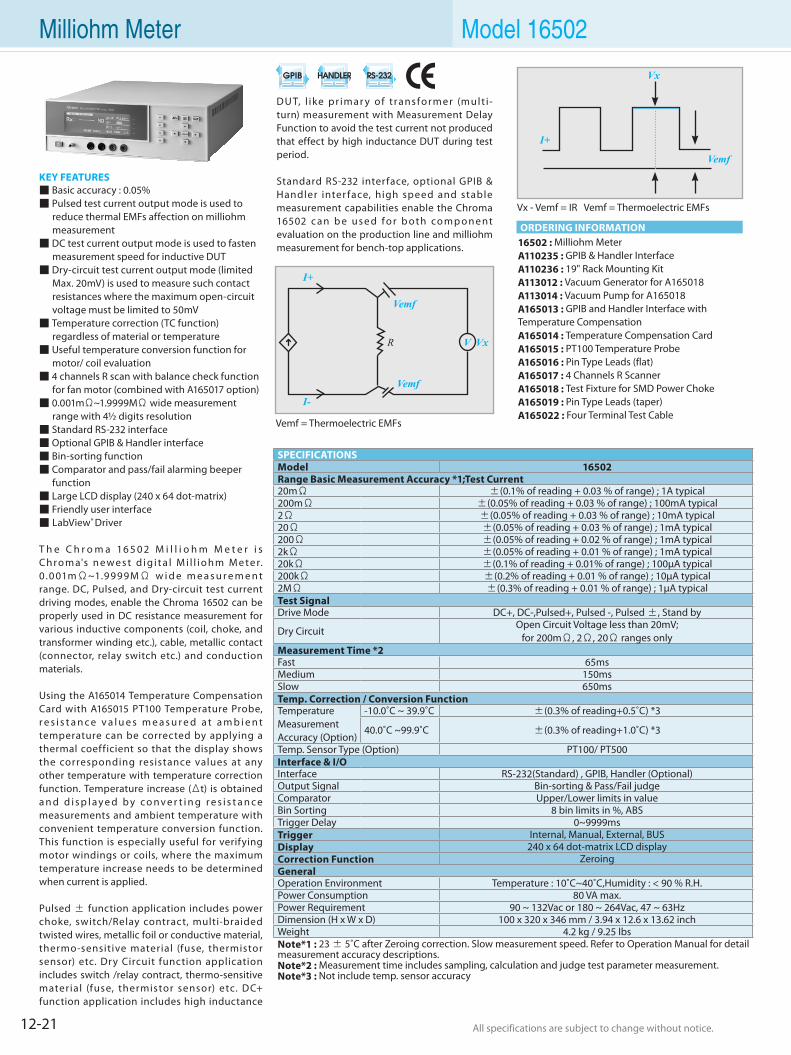
12-21 All specifications are subject to change without notice. All specifications are subject to change without notice.
KEY FEATURES Basic accuracy : 0.05% Pulsed test current output mode is used to reduce thermal EMFs affection on milliohm measurement DC test current output mode is used to fasten measurement speed for inductive DUT Dry-circuit test current output mode (limited Max. 20mV) is used to measure such contact resistances where the maximum open-circuit voltage must be limited to 50mV Temperature correction (TC function) regardless of material or temperature Useful temperature conversion function for motor/ coil evaluation 4 channels R scan with balance check function for fan motor (combined with A165017 option) 0.001mΩ~1.9999MΩ wide measurement range with 4½ digits resolution Standard RS-232 interface Optional GPIB & Handler interface Bin-sorting function Comparator and pass/fail alarming beeper function Large LCD display (240 x 64 dot-matrix) Friendly user interface LabView® Driver
T h e C h r o m a 16 5 0 2 M i l l i o h m M e t e r i s C h r o m a's n e w e s t d i g i t a l M i l l i o h m M e te r. 0 .0 01mΩ~1.9 99 9MΩ w i d e m e a s u r e m e n t range. DC, Pulsed, and Dry-circuit test current driving modes, enable the Chroma 16502 can be properly used in DC resistance measurement for various inductive components (coil, choke, and transformer winding etc.), cable, metallic contact (connector, relay switch etc.) and conduction materials.
Using the A165014 Temperature Compensation Card with A165015 PT100 Temperature Probe, r e s i s t a n c e v a l u e s m e a s u r e d a t a m b i e n t temperature can be corrected by applying a thermal coefficient so that the display shows the corresponding resistance values at any other temperature with temperature correction function. Temperature increase (Δt) is obtained a n d d i s p l a y e d b y c o n v e r t i n g r e s i s t a n c e measurements and ambient temperature with convenient temperature conversion function. This function is especially useful for verifying motor windings or coils, where the maximum temperature increase needs to be determined when current is applied.
Pulsed ± function application includes power choke, switch/Relay contract, multi-braided twisted wires, metallic foil or conductive material, thermo-sensitive material (fuse, thermistor sensor) etc. Dry Circuit function application includes switch /relay contract, thermo-sensitive material (fuse, thermistor sensor) etc. DC+ function application includes high inductance
16502 : Milliohm MeterA110235 : GPIB & Handler InterfaceA110236 : 19" Rack Mounting KitA113012 : Vacuum Generator for A165018A113014 : Vacuum Pump for A165018A165013 : GPIB and Handler Interface with Temperature CompensationA165014 : Temperature Compensation CardA165015 : PT100 Temperature ProbeA165016 : Pin Type Leads (flat)A165017 : 4 Channels R ScannerA165018 : Test Fixture for SMD Power ChokeA165019 : Pin Type Leads (taper)A165022 : Four Terminal Test Cable
DU T, l ike pr imar y of t r ans for m er (mult i-turn) measurement with Measurement Delay Function to avoid the test current not produced that effect by high inductance DUT during test period.
Standard RS-232 interface, optional GPIB & Handler inter face, high speed and stable measurement capabilities enable the Chroma 16502 c a n b e us e d f o r b o t h co m p o n e nt evaluation on the production line and milliohm measurement for bench-top applications.
SPECIFICATIONSModel 16502Range Basic Measurement Accuracy *1;Test Current20mΩ ±(0.1% of reading + 0.03 % of range) ; 1A typical200mΩ ±(0.05% of reading + 0.03 % of range) ; 100mA typical2Ω ±(0.05% of reading + 0.03 % of range) ; 10mA typical20Ω ±(0.05% of reading + 0.03 % of range) ; 1mA typical200Ω ±(0.05% of reading + 0.02 % of range) ; 1mA typical2kΩ ±(0.05% of reading + 0.01 % of range) ; 1mA typical20kΩ ±(0.1% of reading + 0.01% of range) ; 100µA typical200kΩ ±(0.2% of reading + 0.01 % of range) ; 10µA typical2MΩ ±(0.3% of reading + 0.01 % of range) ; 1µA typicalTest SignalDrive Mode DC+, DC-,Pulsed+, Pulsed -, Pulsed ±, Stand by
Dry CircuitOpen Circuit Voltage less than 20mV;
for 200mΩ, 2Ω, 20Ω ranges onlyMeasurement Time *2Fast 65msMedium 150msSlow 650msTemp. Correction / Conversion FunctionTemperatureMeasurementAccuracy (Option)
-10.0˚C ~ 39.9˚C ±(0.3% of reading+0.5˚C) *3
40.0˚C ~99.9˚C ±(0.3% of reading+1.0˚C) *3
Temp. Sensor Type (Option) PT100/ PT500Interface & I/OInterface RS-232(Standard) , GPIB, Handler (Optional)Output Signal Bin-sorting & Pass/Fail judgeComparator Upper/Lower limits in valueBin Sorting 8 bin limits in %, ABSTrigger Delay 0~9999msTrigger Internal, Manual, External, BUSDisplay 240 x 64 dot-matrix LCD displayCorrection Function ZeroingGeneralOperation Environment Temperature : 10˚C~40˚C,Humidity : < 90 % R.H.Power Consumption 80 VA max.Power Requirement 90 ~ 132Vac or 180 ~ 264Vac, 47 ~ 63HzDimension (H x W x D) 100 x 320 x 346 mm / 3.94 x 12.6 x 13.62 inchWeight 4.2 kg / 9.25 lbsNote*1 : 23 ± 5˚C after Zeroing correction. Slow measurement speed. Refer to Operation Manual for detail measurement accuracy descriptions. Note*2 : Measurement time includes sampling, calculation and judge test parameter measurement.Note*3 : Not include temp. sensor accuracy
Milliohm Meter Model 16502
ORDERING INFORMATION
Vemf = Thermoelectric EMFs
Vx - Vemf = IR Vemf = Thermoelectric EMFs
Vx
Vemf
I+
I+
I-
Vemf
Vemf
V VxR
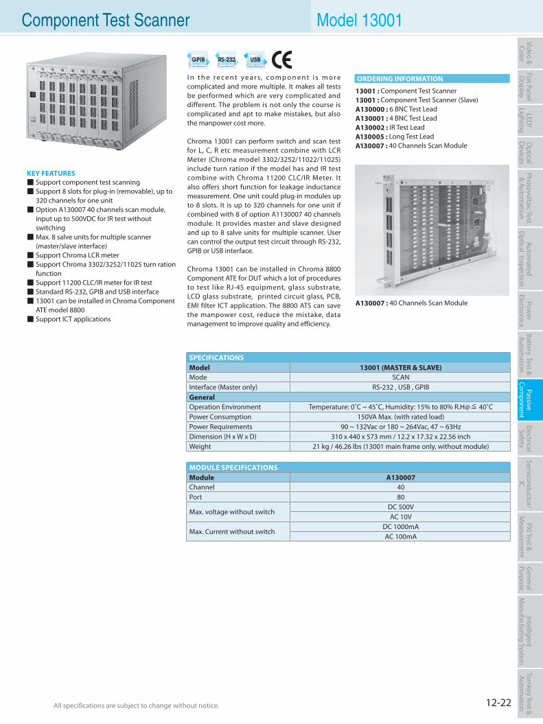
12-22All specifications are subject to change without notice. All specifications are subject to change without notice.
Flat PanelD
isplayPow
er Electronics
Electrical Safety
General
PurposePassive
Component
Semiconductor/
ICBattery Test & Autom
ationAutom
atedO
ptical Inspection Photovoltaic Test
& Automation
PXI Test &
Measurem
ent Video & Color
LED/
LightingO
ptical D
evicesIntelligent
Manufacturing System
Turnkey Test & Autom
ation
KEY FEATURES Support component test scanning Support 8 slots for plug-in (removable), up to 320 channels for one unit Option A130007 40 channels scan module, input up to 500VDC for IR test without switching Max. 8 salve units for multiple scanner (master/slave interface) Support Chroma LCR meter Support Chroma 3302/3252/11025 turn ration function Support 11200 CLC/IR meter for IR test Standard RS-232, GPIB and USB interface 13001 can be installed in Chroma Component ATE model 8800 Support ICT applications
13001 : Component Test Scanner13001 : Component Test Scanner (Slave)A130000 : 6 BNC Test LeadA130001 : 4 BNC Test LeadA130002 : IR Test LeadA130005 : Long Test LeadA130007 : 40 Channels Scan Module
I n t h e r e c e n t y e a r s, c o m p o n e n t i s m o r e complicated and more multiple. It makes all tests be performed which are very complicated and different. The problem is not only the course is complicated and apt to make mistakes, but also the manpower cost more.
Chroma 13001 can perform switch and scan test for L, C, R etc measurement combine with LCR Meter (Chroma model 3302/3252/11022/11025) include turn ration if the model has and IR test combine with Chroma 11200 CLC/IR Meter. It also offers short function for leakage inductance measurement. One unit could plug-in modules up to 8 slots. It is up to 320 channels for one unit if combined with 8 of option A1130007 40 channels module. It provides master and slave designed and up to 8 salve units for multiple scanner. User can control the output test circuit through RS-232, GPIB or USB interface.
Chroma 13001 can be installed in Chroma 8800 Component ATE for DUT which a lot of procedures to test like RJ-45 equipment, glass substrate, LCD glass substrate, printed circuit glass, PCB, EMI filter ICT application. The 8800 ATS can save the manpower cost, reduce the mistake, data management to improve quality and efficiency.
A130007 : 40 Channels Scan Module
SPECIFICATIONSModel 13001 (MASTER & SLAVE)Mode SCANInterface (Master only) RS-232 , USB , GPIB GeneralOperation Environment Temperature: 0˚C ~ 45˚C, Humidity: 15% to 80% R.H@≦ 40˚CPower Consumption 150VA Max. (with rated load)Power Requirements 90 ~ 132Vac or 180 ~ 264Vac, 47 ~ 63HzDimension (H x W x D) 310 x 440 x 573 mm / 12.2 x 17.32 x 22.56 inchWeight 21 kg / 46.26 lbs (13001 main frame only, without module)
MODULE SPECIFICATIONSModule A130007Channel 40Port 80
Max. voltage without switchDC 500VAC 10V
Max. Current without switchDC 1000mAAC 100mA
Component Test Scanner Model 13001
ORDERING INFORMATION
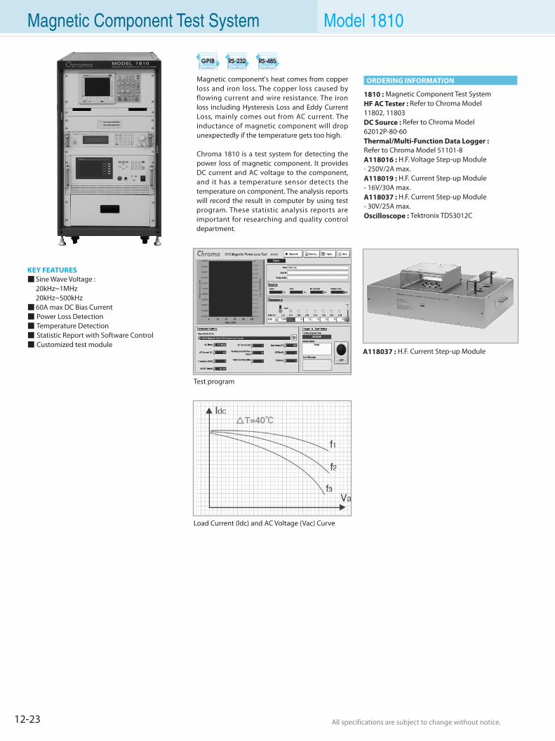
12-23 All specifications are subject to change without notice. All specifications are subject to change without notice.
Magnetic Component Test System Model 1810
KEY FEATURES Sine Wave Voltage : 20kHz~1MHz 20kHz~500kHz 60A max DC Bias Current Power Loss Detection Temperature Detection Statistic Report with Software Control Customized test module
Magnetic component's heat comes from copper loss and iron loss. The copper loss caused by flowing current and wire resistance. The iron loss including Hysteresis Loss and Eddy Current Loss, mainly comes out from AC current. The inductance of magnetic component will drop unexpectedly if the temperature gets too high.
Chroma 1810 is a test system for detecting the power loss of magnetic component. It provides DC current and AC voltage to the component, and it has a temperature sensor detects the temperature on component. The analysis reports will record the result in computer by using test program. These statistic analysis reports are important for researching and quality control department.
1810 : Magnetic Component Test SystemHF AC Tester : Refer to Chroma Model 11802, 11803DC Source : Refer to Chroma Model 62012P-80-60Thermal/Multi-Function Data Logger : Refer to Chroma Model 51101-8A118016 : H.F. Voltage Step-up Module- 250V/2A max.A118019 : H.F. Current Step-up Module- 16V/30A max.A118037 : H.F. Current Step-up Module - 30V/25A max. Oscilloscope : Tektronix TDS3012C
ORDERING INFORMATION
Test program
A118037 : H.F. Current Step-up Module
Load Current (ldc) and AC Voltage (Vac) Curve
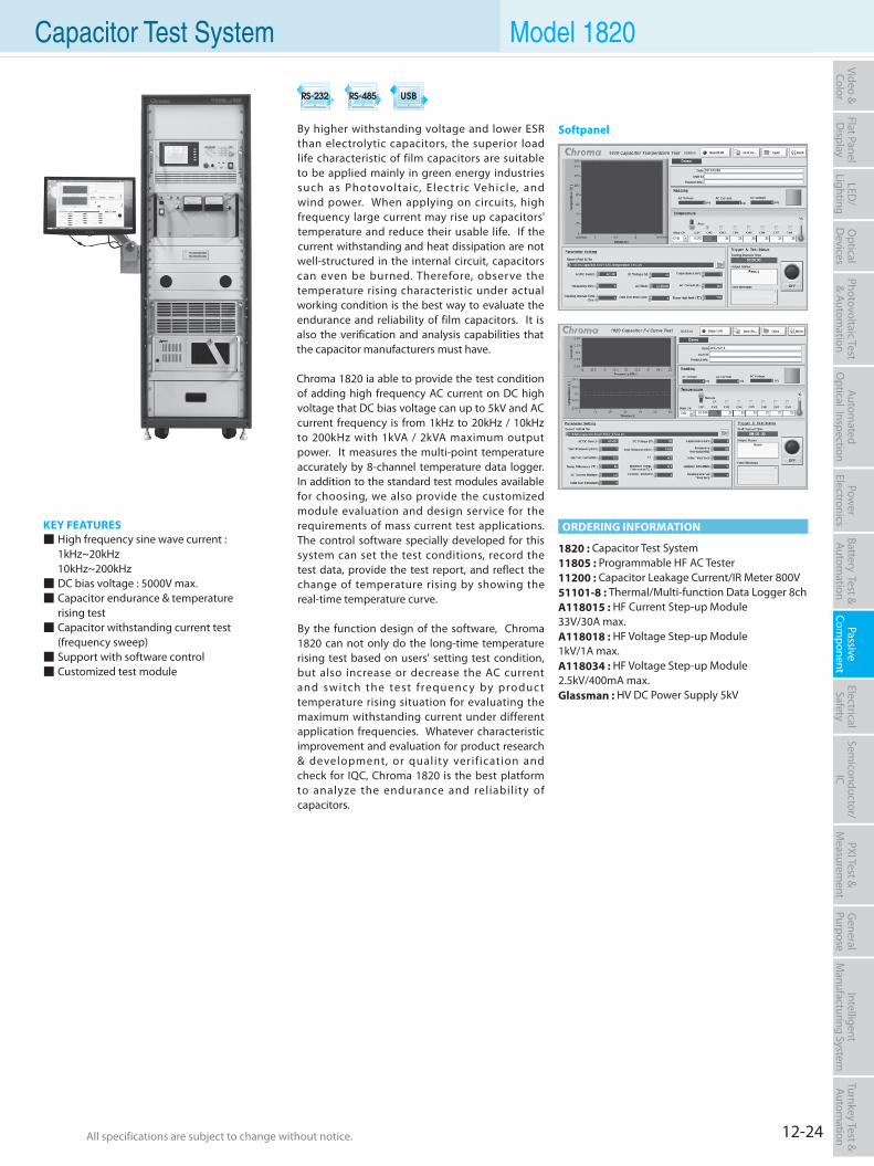
12-24All specifications are subject to change without notice. All specifications are subject to change without notice.
Flat PanelD
isplayPow
er Electronics
Electrical Safety
General
PurposePassive
Component
Semiconductor/
ICBattery Test & Autom
ationAutom
atedO
ptical Inspection Photovoltaic Test
& Automation
PXI Test &
Measurem
ent Video & Color
LED/
LightingO
ptical D
evicesIntelligent
Manufacturing System
Turnkey Test & Autom
ation Capacitor Test System Model 1820
KEY FEATURES High frequency sine wave current : 1kHz~20kHz 10kHz~200kHz DC bias voltage : 5000V max. Capacitor endurance & temperature rising test Capacitor withstanding current test (frequency sweep) Support with software control Customized test module
By higher withstanding voltage and lower ESR than electrolytic capacitors, the superior load life characteristic of film capacitors are suitable to be applied mainly in green energy industries such as Photovoltaic, Electr ic Vehicle, and wind power. When applying on circuits, high frequency large current may rise up capacitors' temperature and reduce their usable life. If the current withstanding and heat dissipation are not well-structured in the internal circuit, capacitors can even be burned. Therefore, observe the temperature rising characteristic under actual working condition is the best way to evaluate the endurance and reliability of film capacitors. It is also the verification and analysis capabilities that the capacitor manufacturers must have.
Chroma 1820 ia able to provide the test condition of adding high frequency AC current on DC high voltage that DC bias voltage can up to 5kV and AC current frequency is from 1kHz to 20kHz / 10kHz to 200kHz with 1kVA / 2kVA maximum output power. It measures the multi-point temperature accurately by 8-channel temperature data logger. In addition to the standard test modules available for choosing, we also provide the customized module evaluation and design service for the requirements of mass current test applications. The control software specially developed for this system can set the test conditions, record the test data, provide the test report, and reflect the change of temperature rising by showing the real-time temperature curve.
By the function design of the software, Chroma 1820 can not only do the long-time temperature rising test based on users' setting test condition, but also increase or decrease the AC current and switch the test f requenc y by produc t temperature rising situation for evaluating the maximum withstanding current under different application frequencies. Whatever characteristic improvement and evaluation for product research & development, or quality verif ication and check for IQC, Chroma 1820 is the best platform to analyze the endurance and reliability of capacitors.
1820 : Capacitor Test System11805 : Programmable HF AC Tester11200 : Capacitor Leakage Current/IR Meter 800V51101-8 : Thermal/Multi-function Data Logger 8chA118015 : HF Current Step-up Module33V/30A max.A118018 : HF Voltage Step-up Module1kV/1A max.A118034 : HF Voltage Step-up Module2.5kV/400mA max.Glassman : HV DC Power Supply 5kV
ORDERING INFORMATION
Softpanel
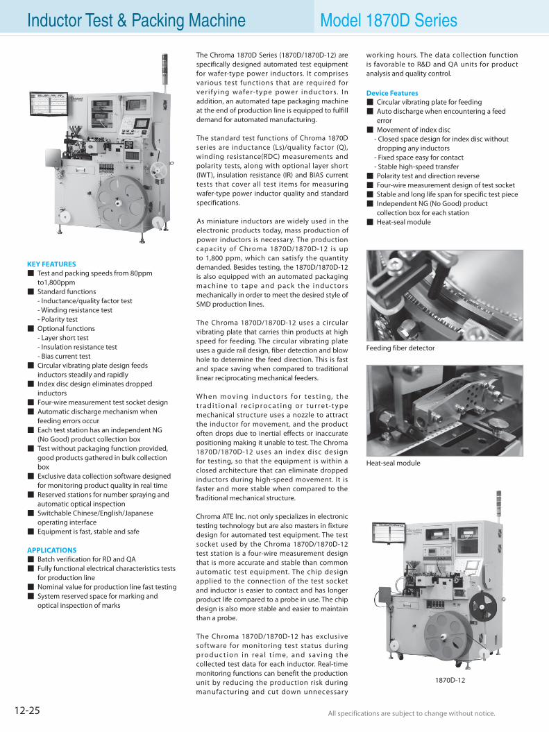
12-25 All specifications are subject to change without notice. All specifications are subject to change without notice.
Inductor Test & Packing Machine Model 1870D Series
KEY FEATURES Test and packing speeds from 80ppm to1,800ppm Standard functions - Inductance/quality factor test - Winding resistance test - Polarity test Optional functions - Layer short test - Insulation resistance test - Bias current test Circular vibrating plate design feeds inductors steadily and rapidly Index disc design eliminates dropped inductors Four-wire measurement test socket design Automatic discharge mechanism when feeding errors occur Each test station has an independent NG (No Good) product collection box Test without packaging function provided, good products gathered in bulk collection box Exclusive data collection software designed for monitoring product quality in real time Reserved stations for number spraying and automatic optical inspection Switchable Chinese/English/Japanese operating interface Equipment is fast, stable and safe
APPLICATIONS Batch verification for RD and QA Fully functional electrical characteristics tests for production line Nominal value for production line fast testing System reserved space for marking and optical inspection of marks
1870D-12
Heat-seal module
Feeding fiber detector
*
The Chroma 1870D Series (1870D/1870D-12) are specifically designed automated test equipment for wafer-type power inductors. It comprises various test functions that are required for ver i fy ing wafer-t ype power induc tors. I n addition, an automated tape packaging machine at the end of production line is equipped to fulfill demand for automated manufacturing.
The standard test functions of Chroma 1870D series are inductance (Ls)/quality factor (Q), winding resistance(RDC) measurements and polarity tests, along with optional layer short (IWT), insulation resistance (IR) and BIAS current tests that cover all test items for measuring wafer-type power inductor quality and standard specifications.
As miniature inductors are widely used in the electronic products today, mass production of power inductors is necessary. The production capacity of Chroma 1870D/1870D-12 is up to 1,800 ppm, which can satisfy the quantity demanded. Besides testing, the 1870D/1870D-12 is also equipped with an automated packaging machine to tape and pack the induc tors mechanically in order to meet the desired style of SMD production lines.
The Chroma 1870D/1870D-12 uses a circular vibrating plate that carries thin products at high speed for feeding. The circular vibrating plate uses a guide rail design, fiber detection and blow hole to determine the feed direction. This is fast and space saving when compared to traditional linear reciprocating mechanical feeders.
Wh e n m ov i n g i n d u c to r s fo r te s t i n g, t h e t r a d i t i o n a l r e c i p r o c a t i n g o r t u r r e t-t y p e mechanical structure uses a nozzle to attract the inductor for movement, and the product often drops due to inertial effects or inaccurate positioning making it unable to test. The Chroma 1870D/1870D-12 uses an index disc design for testing, so that the equipment is within a closed architecture that can eliminate dropped inductors during high-speed movement. It is faster and more stable when compared to the traditional mechanical structure.
Chroma ATE Inc. not only specializes in electronic testing technology but are also masters in fixture design for automated test equipment. The test socket used by the Chroma 1870D/1870D-12 test station is a four-wire measurement design that is more accurate and stable than common automatic test equipment. The chip design applied to the connection of the test socket and inductor is easier to contact and has longer product life compared to a probe in use. The chip design is also more stable and easier to maintain than a probe.
The Chroma 1870D/1870D-12 has exclusive software for monitoring test status during p ro d u c t i o n i n re a l t i m e, a n d s av i n g t h e collected test data for each inductor. Real-time monitoring functions can benefit the production unit by reducing the production risk during manufacturing and cut down unnecessary
working hours. The data collection function is favorable to R&D and QA units for product analysis and quality control.
Device Features Circular vibrating plate for feeding Auto discharge when encountering a feed error Movement of index disc - Closed space design for index disc without dropping any inductors - Fixed space easy for contact - Stable high-speed transfer Polarity test and direction reverse Four-wire measurement design of test socket Stable and long life span for specific test piece Independent NG (No Good) product collection box for each station Heat-seal module
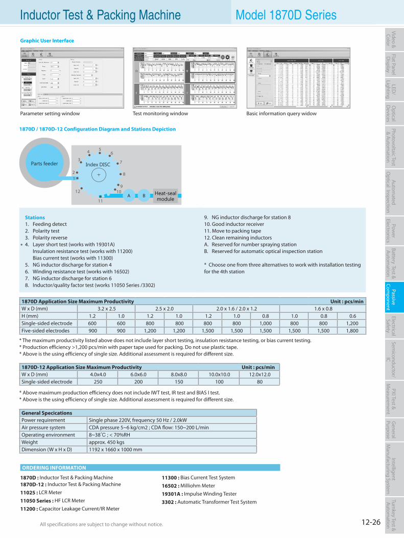
12-26All specifications are subject to change without notice. All specifications are subject to change without notice.
Flat PanelD
isplayPow
er Electronics
Electrical Safety
General
PurposePassive
Component
Semiconductor/
ICBattery Test & Autom
ationAutom
atedO
ptical Inspection Photovoltaic Test
& Automation
PXI Test &
Measurem
ent Video & Color
LED/
LightingO
ptical D
evicesIntelligent
Manufacturing System
Turnkey Test & Autom
ation Inductor Test & Packing Machine Model 1870D Series
1870D : Inductor Test & Packing Machine1870D-12 : Inductor Test & Packing Machine
11025 : LCR Meter
11050 Series : HF LCR Meter
11200 : Capacitor Leakage Current/IR Meter
11300 : Bias Current Test System
16502 : Milliohm Meter
19301A : Impulse Winding Tester
3302 : Automatic Transformer Test System
1870D / 1870D-12 Configuration Diagram and Stations Depiction
Stations1. Feeding detect2. Polarity test3. Polarity reverse4. Layer short test (works with 19301A) Insulation resistance test (works with 11200) Bias current test (works with 11300)5. NG inductor discharge for station 46. Winding resistance test (works with 16502)7. NG inductor discharge for station 68. Inductor/quality factor test (works 11050 Series /3302)
9. NG inductor discharge for station 810. Good inductor receiver11. Move to packing tape12. Clean remaining inductorsA. Reserved for number spraying stationB. Reserved for automatic optical inspection station
* Choose one from three alternatives to work with installation testingfor the 4th station
Parameter setting window Test monitoring window Basic information query widow
ORDERING INFORMATION
Graphic User Interface
Parts feeder
Heat-sealmodule
A B10
12
3
54 6
7
8
9
11
12
Index DISC
* The maximum productivity listed above does not include layer short testing, insulation resistance testing, or bias current testing.* Production efficiency >1,200 pcs/min with paper tape used for packing. Do not use plastic tape.* Above is the using efficiency of single size. Additional assessment is required for different size.
* Above maximum production efficiency does not include IWT test, IR test and BIAS I test.* Above is the using efficiency of single size. Additional assessment is required for different size.
1870D Application Size Maximum Productivity Unit : pcs/minW x D (mm) 3.2 x 2.5 2.5 x 2.0 2.0 x 1.6 / 2.0 x 1.2 1.6 x 0.8 H (mm) 1.2 1.0 1.2 1.0 1.2 1.0 0.8 1.0 0.8 0.6Single-sided electrode 600 600 800 800 800 800 1,000 800 800 1,200 Five-sided electrodes 900 900 1,200 1,200 1,500 1,500 1,500 1,500 1,500 1,800
1870D-12 Application Size Maximum Productivity Unit : pcs/min W x D (mm) 4.0x4.0 6.0x6.0 8.0x8.0 10.0x10.0 12.0x12.0Single-sided electrode 250 200 150 100 80
*
General SpecicationsPower requirement Single phase 220V, frequency 50 Hz / 2.0kWAir pressure system CDA pressure 5~6 kg/cm2 ; CDA flow: 150~200 L/minOperating environment 8~38 ; < 70%RHWeight approx. 450 kgsDimension (W x H x D) 1192 x 1660 x 1000 mm
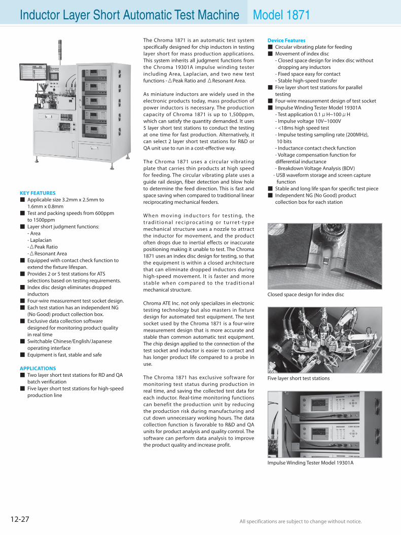
12-27 All specifications are subject to change without notice. All specifications are subject to change without notice.
Inductor Layer Short Automatic Test Machine Model 1871
KEY FEATURES Applicable size 3.2mm x 2.5mm to 1.6mm x 0.8mm Test and packing speeds from 600ppm to 1500ppm Layer short judgment functions: - Area - Laplacian -ΔPeak Ratio -ΔResonant Area Equipped with contact check function to
extend the fixture lifespan. Provides 2 or 5 test stations for ATS
selections based on testing requirements. Index disc design eliminates dropped
inductors Four-wire measurement test socket design. Each test station has an independent NG
(No Good) product collection box. Exclusive data collection software
designed for monitoring product quality in real time Switchable Chinese/English/Japanese
operating interface Equipment is fast, stable and safe
APPLICATIONS Two layer short test stations for RD and QA batch verification Five layer short test stations for high-speed production line
Five layer short test stations
Impulse Winding Tester Model 19301A
Closed space design for index disc
The Chroma 1871 is an automatic test system specifically designed for chip inductors in testing layer short for mass production applications. This system inherits all judgment functions from the Chroma 19301A impulse winding tester including Area, Laplacian, and two new test functions -ΔPeak Ratio and ΔResonant Area.
As miniature inductors are widely used in the electronic products today, mass production of power inductors is necessary. The production capacity of Chroma 1871 is up to 1,500ppm, which can satisfy the quantity demanded. It uses 5 layer short test stations to conduct the testing at one time for fast production. Alternatively, it can select 2 layer short test stations for R&D or QA unit use to run in a cost-effective way.
The Chroma 1871 uses a circular vibrating plate that carries thin products at high speed for feeding. The circular vibrating plate uses a guide rail design, fiber detection and blow hole to determine the feed direction. This is fast and space saving when compared to traditional linear reciprocating mechanical feeders.
Wh e n m ov i n g i n d u c to r s fo r te s t i n g, t h e t r a d i t i o n a l r e c i p r o c a t i n g o r t u r r e t-t y p e mechanical structure uses a nozzle to attract the inductor for movement, and the product often drops due to inertial effects or inaccurate positioning making it unable to test. The Chroma 1871 uses an index disc design for testing, so that the equipment is within a closed architecture that can eliminate dropped inductors during high-speed movement. It is faster and more stable when compared to the tradit ional mechanical structure.
Chroma ATE Inc. not only specializes in electronic testing technology but also masters in fixture design for automated test equipment. The test socket used by the Chroma 1871 is a four-wire measurement design that is more accurate and stable than common automatic test equipment. The chip design applied to the connection of the test socket and inductor is easier to contact and has longer product life compared to a probe in use.
The Chroma 1871 has exclusive software for monitoring test status during production in real time, and saving the collected test data for each inductor. Real-time monitoring functions can benefit the production unit by reducing the production risk during manufacturing and cut down unnecessary working hours. The data collection function is favorable to R&D and QA units for product analysis and quality control. The software can perform data analysis to improve the product quality and increase profit.
Device Features Circular vibrating plate for feeding Movement of index disc - Closed space design for index disc without dropping any inductors - Fixed space easy for contact - Stable high-speed transfer Five layer short test stations for parallel testing Four-wire measurement design of test socket Impulse Winding Tester Model 19301A - Test application 0.1μH~100μH - Impulse voltage 10V~1000V - <18ms high speed test - Impulse testing sampling rate (200MHz), 10 bits - Inductance contact check function - Voltage compensation function for differential inductance - Breakdown Voltage Analysis (BDV) - USB waveform storage and screen capture function Stable and long life span for specific test piece Independent NG (No Good) product collection box for each station
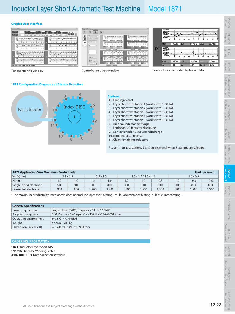
12-28All specifications are subject to change without notice. All specifications are subject to change without notice.
Flat PanelD
isplayPow
er Electronics
Electrical Safety
General
PurposePassive
Component
Semiconductor/
ICBattery Test & Autom
ationAutom
atedO
ptical Inspection Photovoltaic Test
& Automation
PXI Test &
Measurem
ent Video & Color
LED/
LightingO
ptical D
evicesIntelligent
Manufacturing System
Turnkey Test & Autom
ation Inductor Layer Short Automatic Test Machine Model 1871
1871 : Inductor Layer Short ATS19301A : Impulse Winding TesterA187100 : 1871 Data collection software
1871 Configuration Diagram and Station Depiction
Stations1. Feeding detect2. Layer short test station 1 (works with 19301A)3. Layer short test station 2 (works with 19301A)4. Layer short test station 3 (works with 19301A)5. Layer short test station 4 (works with 19301A)6. Layer short test station 5 (works with 19301A)7. Area NG inductor discharge8. Laplacian NG inductor discharge9. Contact check NG inductor discharge10. Good inductor receiver11. Clean remaining inductors
* Layer short test stations 3 to 5 are reserved when 2 stations are selected.
Test monitoring window Control limits calculated by tested dataControl chart query window
ORDERING INFORMATION
Graphic User Interface
10
1
2
4
5
3
6
789
11
Parts feeder Index DISC
General SpecificationsPower requirement Single phase 220V ; frequency 60 Hz / 2.0kWAir pressure system CDA Pressure 5~6 kg/cm2,CDA Flow150~200 L/minOperating environment 8~38,< 70%RHWeight Approx. 500 kgDimension (W x H x D) W 1280 x H 1495 x D 900 mm
* The maximum productivity listed above does not include layer short testing, insulation resistance testing, or bias current testing.
1871 Application Size Maximum Productivity Unit : pcs/min WxD(mm) 3.2 x 2.5 2.5 x 2.0 2.0 x 1.6 / 2.0 x 1.2 1.6 x 0.8H(mm) 1.2 1.0 1.2 1.0 1.2 1.0 0.8 1.0 0.8 0.6Single-sided electrode 600 600 800 800 800 800 800 800 800 800 Five-sided electrodes 900 900 1,200 1,200 1,500 1,500 1,500 1,500 1,500 1,500
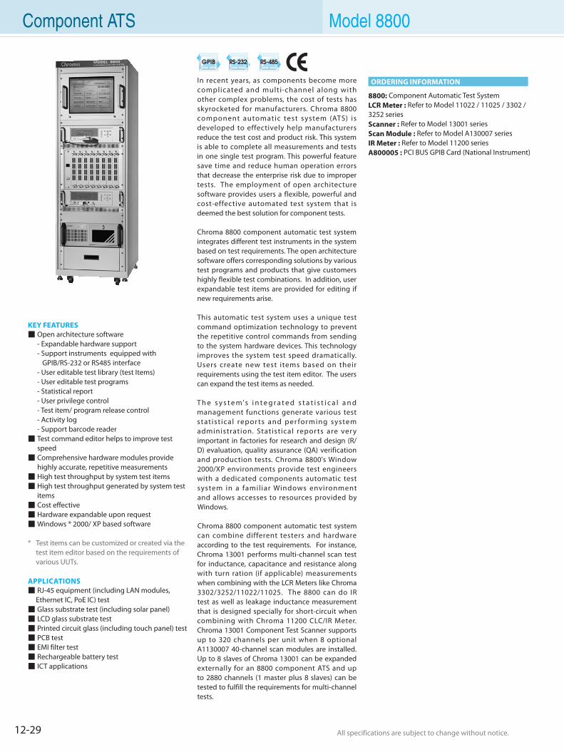
12-29 All specifications are subject to change without notice. All specifications are subject to change without notice.
Component ATS Model 8800
KEY FEATURES Open architecture software - Expandable hardware support - Support instruments equipped with GPIB/RS-232 or RS485 interface - User editable test library (test Items) - User editable test programs - Statistical report - User privilege control - Test item/ program release control - Activity log - Support barcode reader Test command editor helps to improve test
speed Comprehensive hardware modules provide
highly accurate, repetitive measurements High test throughput by system test items High test throughput generated by system test
items Cost effective Hardware expandable upon request Windows ® 2000/ XP based software
* Test items can be customized or created via the test item editor based on the requirements of various UUTs.
APPLICATIONS RJ-45 equipment (including LAN modules,
Ethernet IC, PoE IC) test Glass substrate test (including solar panel) LCD glass substrate test Printed circuit glass (including touch panel) test PCB test EMI filter test Rechargeable battery test ICT applications
In recent years, as components become more complicated and multi-channel along with other complex problems, the cost of tests has skyrocketed for manufacturers. Chroma 8800 component automatic test system (ATS) is developed to effectively help manufacturers reduce the test cost and product risk. This system is able to complete all measurements and tests in one single test program. This powerful feature save time and reduce human operation errors that decrease the enterprise risk due to improper tests. The employment of open architecture software provides users a flexible, powerful and cost-effective automated test system that is deemed the best solution for component tests. Chroma 8800 component automatic test system integrates different test instruments in the system based on test requirements. The open architecture software offers corresponding solutions by various test programs and products that give customers highly flexible test combinations. In addition, user expandable test items are provided for editing if new requirements arise.
This automatic test system uses a unique test command optimization technology to prevent the repetitive control commands from sending to the system hardware devices. This technology improves the system test speed dramatically. Users create new test items based on their requirements using the test item editor. The users can expand the test items as needed.
T h e s y s t e m's i n t e g r a t e d s t a t i s t i c a l a n d management functions generate various test stat ist ical repor ts and per forming system administration. Statistical repor ts are ver y important in factories for research and design (R/D) evaluation, quality assurance (QA) verification and production tests. Chroma 8800's Window 2000/XP environments provide test engineers with a dedicated components automatic test system in a familiar Windows environment and allows accesses to resources provided by Windows.
Chroma 8800 component automatic test system can combine different testers and hardware according to the test requirements. For instance, Chroma 13001 performs multi-channel scan test for inductance, capacitance and resistance along with turn ration (if applicable) measurements when combining with the LCR Meters like Chroma 3302/3252/11022/11025. The 8800 can do IR test as well as leakage inductance measurement that is designed specially for short-circuit when combining with Chroma 11200 CLC/IR Meter. Chroma 13001 Component Test Scanner supports up to 320 channels per unit when 8 optional A1130007 40-channel scan modules are installed. Up to 8 slaves of Chroma 13001 can be expanded externally for an 8800 component ATS and up to 2880 channels (1 master plus 8 slaves) can be tested to fulfill the requirements for multi-channel tests.
8800: Component Automatic Test SystemLCR Meter : Refer to Model 11022 / 11025 / 3302 / 3252 seriesScanner : Refer to Model 13001 seriesScan Module : Refer to Model A130007 seriesIR Meter : Refer to Model 11200 seriesA800005 : PCI BUS GPIB Card (National Instrument)
ORDERING INFORMATION
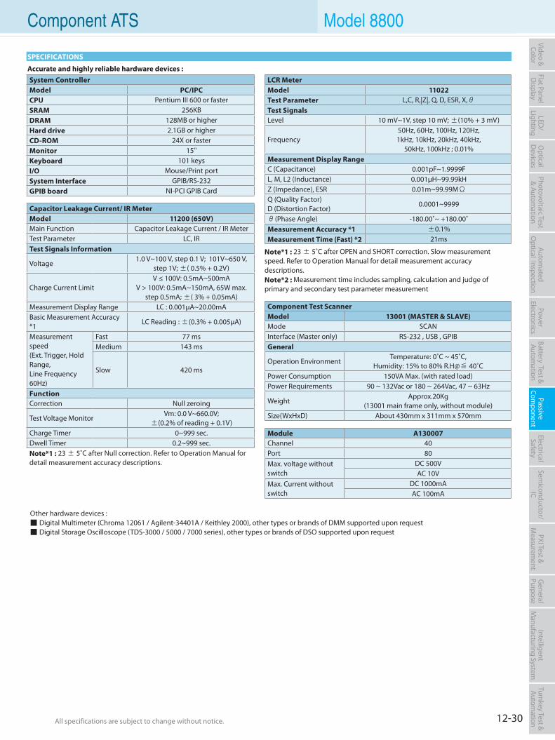
12-30All specifications are subject to change without notice. All specifications are subject to change without notice.
Flat PanelD
isplayPow
er Electronics
Electrical Safety
General
PurposePassive
Component
Semiconductor/
ICBattery Test & Autom
ationAutom
atedO
ptical Inspection Photovoltaic Test
& Automation
PXI Test &
Measurem
ent Video & Color
LED/
LightingO
ptical D
evicesIntelligent
Manufacturing System
Turnkey Test & Autom
ation Component ATS Model 8800
SPECIFICATIONS
Other hardware devices : Digital Multimeter (Chroma 12061 / Agilent-34401A / Keithley 2000), other types or brands of DMM supported upon request Digital Storage Oscilloscope (TDS-3000 / 5000 / 7000 series), other types or brands of DSO supported upon request
Accurate and highly reliable hardware devices :System ControllerModel PC/IPCCPU Pentium III 600 or fasterSRAM 256KB DRAM 128MB or higherHard drive 2.1GB or higherCD-ROM 24X or fasterMonitor 15''Keyboard 101 keysI/O Mouse/Print portSystem Interface GPIB/RS-232GPIB board NI-PCI GPIB Card
LCR MeterModel 11022Test Parameter L,C, R,|Z|, Q, D, ESR, X,θTest SignalsLevel 10 mV~1V, step 10 mV; ±(10% + 3 mV)
Frequency50Hz, 60Hz, 100Hz, 120Hz,1kHz, 10kHz, 20kHz, 40kHz,
50kHz, 100kHz ; 0.01%Measurement Display RangeC (Capacitance) 0.001pF~1.9999FL, M, L2 (Inductance) 0.001µH~99.99kHZ (Impedance), ESR 0.01m~99.99MΩQ (Quality Factor)D (Distortion Factor)
0.0001~9999
θ(Phase Angle) -180.00˚~ +180.00˚Measurement Accuracy *1 ±0.1%Measurement Time (Fast) *2 21ms
Note*1 : 23 ± 5˚C after OPEN and SHORT correction. Slow measurement speed. Refer to Operation Manual for detail measurement accuracy descriptions. Note*2 : Measurement time includes sampling, calculation and judge of primary and secondary test parameter measurement
Capacitor Leakage Current/ IR MeterModel 11200 (650V)Main Function Capacitor Leakage Current / IR MeterTest Parameter LC, IRTest Signals Information
Voltage1.0 V~100 V, step 0.1 V; 101V~650 V,
step 1V; ±( 0.5% + 0.2V)
Charge Current LimitV ≤ 100V: 0.5mA~500mA
V > 100V: 0.5mA~150mA, 65W max.step 0.5mA; ±( 3% + 0.05mA)
Measurement Display Range LC : 0.001µA~20.00mABasic Measurement Accuracy *1
LC Reading : ±(0.3% + 0.005µA)
Measurement speed (Ext. Trigger, Hold Range, Line Frequency 60Hz)
Fast 77 msMedium 143 ms
Slow 420 ms
FunctionCorrection Null zeroing
Test Voltage MonitorVm: 0.0 V~660.0V;
±(0.2% of reading + 0.1V)Charge Timer 0~999 sec.Dwell Timer 0.2~999 sec.Note*1 : 23 ± 5˚C after Null correction. Refer to Operation Manual for detail measurement accuracy descriptions.
Component Test ScannerModel 13001 (MASTER & SLAVE)Mode SCANInterface (Master only) RS-232 , USB , GPIB General
Operation EnvironmentTemperature: 0˚C ~ 45˚C,
Humidity: 15% to 80% R.H@≦ 40˚CPower Consumption 150VA Max. (with rated load)Power Requirements 90 ~ 132Vac or 180 ~ 264Vac, 47 ~ 63Hz
WeightApprox.20Kg
(13001 main frame only, without module)Size(WxHxD) About 430mm x 311mm x 570mm
Module A130007Channel 40Port 80Max. voltage without switch
DC 500VAC 10V
Max. Current without switch
DC 1000mAAC 100mA
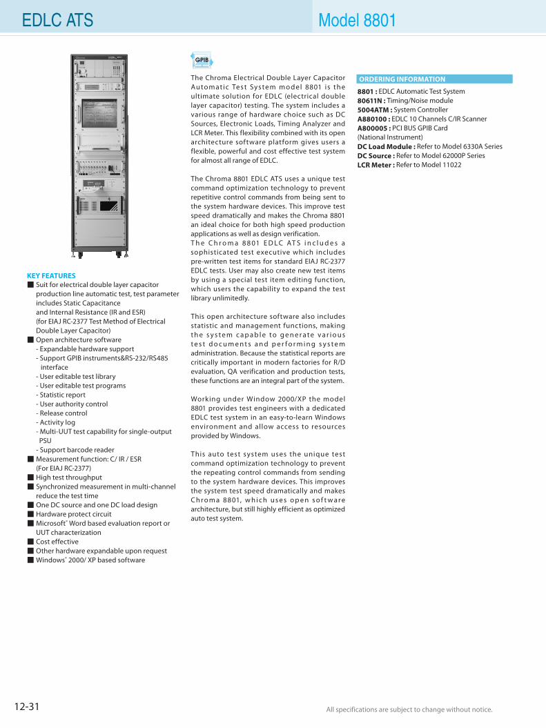
12-31 All specifications are subject to change without notice. All specifications are subject to change without notice.
EDLC ATS Model 8801
KEY FEATURES Suit for electrical double layer capacitor
production line automatic test, test parameter includes Static Capacitance
and Internal Resistance (IR and ESR) (for EIAJ RC-2377 Test Method of Electrical
Double Layer Capacitor) Open architecture software - Expandable hardware support - Support GPIB instruments&RS-232/RS485
interface - User editable test library - User editable test programs - Statistic report - User authority control - Release control - Activity log - Multi-UUT test capability for single-output
PSU - Support barcode reader Measurement function: C/ IR / ESR (For EIAJ RC-2377) High test throughput Synchronized measurement in multi-channel
reduce the test time One DC source and one DC load design Hardware protect circuit Microsoft® Word based evaluation report or
UUT characterization Cost effective Other hardware expandable upon request Windows® 2000/ XP based software
8801 : EDLC Automatic Test System80611N : Timing/Noise module5004ATM : System ControllerA880100 : EDLC 10 Channels C/IR ScannerA800005 : PCI BUS GPIB Card (National Instrument)DC Load Module : Refer to Model 6330A SeriesDC Source : Refer to Model 62000P SeriesLCR Meter : Refer to Model 11022
The Chroma Electrical Double Layer Capacitor Automatic Tes t Sys tem m o de l 8801 is th e ultimate solution for EDLC (electrical double layer capacitor) testing. The system includes a various range of hardware choice such as DC Sources, Electronic Loads, Timing Analyzer and LCR Meter. This flexibility combined with its open architecture software platform gives users a flexible, powerful and cost effective test system for almost all range of EDLC.
The Chroma 8801 EDLC ATS uses a unique test command optimization technology to prevent repetitive control commands from being sent to the system hardware devices. This improve test speed dramatically and makes the Chroma 8801 an ideal choice for both high speed production applications as well as design verification.T h e C h r o m a 8 8 01 E D L C AT S i n c l u d e s a sophisticated test executive which includes pre-written test items for standard EIAJ RC-2377 EDLC tests. User may also create new test items by using a special test item editing function, which users the capability to expand the test library unlimitedly.
This open architecture software also includes statistic and management functions, making t h e s y s t e m c a p a b l e t o g e n e r a t e v a r i o u s t e s t d o c u m e n t s a n d p e r f o r m i n g s y s t e m administration. Because the statistical reports are critically important in modern factories for R/D evaluation, QA verification and production tests, these functions are an integral part of the system.
Working under Window 2000/XP the model 8801 provides test engineers with a dedicated EDLC test system in an easy-to-learn Windows environment and allow access to resources provided by Windows.
This auto test system uses the unique test command optimization technology to prevent the repeating control commands from sending to the system hardware devices. This improves the system test speed dramatically and makes C h r o m a 8801, w h i c h u s e s o p e n s o f t w a r e architecture, but still highly efficient as optimized auto test system.
ORDERING INFORMATION
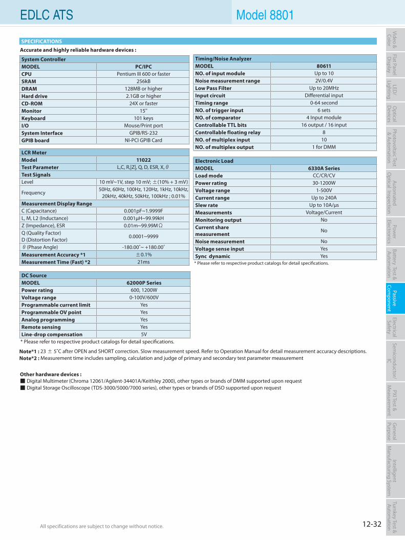
12-32All specifications are subject to change without notice. All specifications are subject to change without notice.
Flat PanelD
isplayPow
er Electronics
Electrical Safety
General
PurposePassive
Component
Semiconductor/
ICBattery Test & Autom
ationAutom
atedO
ptical Inspection Photovoltaic Test
& Automation
PXI Test &
Measurem
ent Video & Color
LED/
LightingO
ptical D
evicesIntelligent
Manufacturing System
Turnkey Test & Autom
ation EDLC ATS Model 8801
SPECIFICATIONS
Accurate and highly reliable hardware devices :
Other hardware devices : Digital Multimeter (Chroma 12061/Agilent-34401A/Keithley 2000), other types or brands of DMM supported upon request Digital Storage Oscilloscope (TDS-3000/5000/7000 series), other types or brands of DSO supported upon request
System ControllerMODEL PC/IPCCPU Pentium III 600 or fasterSRAM 256kB DRAM 128MB or higherHard drive 2.1GB or higherCD-ROM 24X or fasterMonitor 15''Keyboard 101 keysI/O Mouse/Print portSystem Interface GPIB/RS-232GPIB board NI-PCI GPIB Card
Timing/Noise AnalyzerMODEL 80611NO. of input module Up to 10Noise measurement range 2V/0.4VLow Pass Filter Up to 20MHzInput circuit Differential inputTiming range 0-64 secondNO. of trigger input 6 setsNO. of comparator 4 Input moduleControllable TTL bits 16 output / 16 inputControllable floating relay 8NO. of multiplex input 10NO. of multiplex output 1 for DMM
DC SourceMODEL 62000P SeriesPower rating 600, 1200WVoltage range 0-100V/600VProgrammable current limit YesProgrammable OV point YesAnalog programming YesRemote sensing YesLine-drop compensation 5V* Please refer to respective product catalogs for detail specifications.
LCR MeterModel 11022Test Parameter L,C, R,|Z|, Q, D, ESR, X,θTest SignalsLevel 10 mV~1V, step 10 mV; ±(10% + 3 mV)
Frequency50Hz, 60Hz, 100Hz, 120Hz, 1kHz, 10kHz,
20kHz, 40kHz, 50kHz, 100kHz ; 0.01%Measurement Display RangeC (Capacitance) 0.001pF~1.9999FL, M, L2 (Inductance) 0.001µH~99.99kHZ (Impedance), ESR 0.01m~99.99MΩQ (Quality Factor)D (Distortion Factor)
0.0001~9999
θ(Phase Angle) -180.00˚~ +180.00˚Measurement Accuracy *1 ±0.1%Measurement Time (Fast) *2 21ms
Electronic LoadMODEL 6330A SeriesLoad mode CC/CR/CVPower rating 30-1200WVoltage range 1-500VCurrent range Up to 240ASlew rate Up to 10A/µsMeasurements Voltage/CurrentMonitoring output NoCurrent sharemeasurement
No
Noise measurement NoVoltage sense input YesSync dynamic Yes* Please refer to respective product catalogs for detail specifications.
Note*1 : 23 ± 5˚C after OPEN and SHORT correction. Slow measurement speed. Refer to Operation Manual for detail measurement accuracy descriptions. Note*2 : Measurement time includes sampling, calculation and judge of primary and secondary test parameter measurement
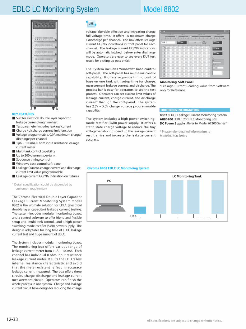
12-33 All specifications are subject to change without notice. All specifications are subject to change without notice.
EDLC LC Monitoring System Model 8802
KEY FEATURES Suit for electrical double layer capacitor
leakage current long time test Test parameter includes leakage current Charge / discharge current limit function Voltage programmable, 0.9A maximum charge/
discharge per-channel 1µA ~ 100mA, 0 ohm input resistance leakage
current meter Multi-tank control capability Up to 200 channels per-tank Sequence timing control Windows base control soft-panel Leakage Current, charge current and discharge
current limit value programmable Leakage current GO/NG indication on fixtures
* Detail specification could be depended by customer requirement
The Chroma Electrical Double Layer Capacitor Leakage Current Monitoring System model 8802 is the ultimate solution for EDLC (electrical double layer capacitor) leakage current testing. The system includes modular monitoring boxes, and a control software to offer friend and flexible setup and multi-tank control, and a high power switching-mode rectifier (SMR) power supply. The design is adaptable for long time of EDLC leakage current test and huge amount of EDLC.
The System includes modular monitoring boxes. The monitoring box offers various range of leakage current meter from 1µA – 100mA. Each channel has individual 0 ohm input resistance leakage current meter. It suits the EDLC's low internal resistance characteristic and avoid that the meter existent effect inaccuracy leakage current measured. The box offers three circuits, charge, discharge and leakage current measurement circuit. Operators can finish the whole process in one system. Charge and leakage current circuit have design for reducing the charge
voltage alterable affection and increasing charge full voltage time. It offers 1A maximum charge / discharge per channel. The box offers leakage current GO/NG indications in front panel for each channel. The leakage current GO/NG indications will be automatic latched before enter discharge mode. Operators are easy to see every DUT test result for picking up pass or fail.
The System includes Windows® base control soft-panel. The soft-panel has multi-tank control capability. It offers sequence timing control base on one tank with setup time for charge, measurement leakage current, and discharge. The process bar is easy for operators to see the test process. Operators can set current limit values of leakage current, charge current, and discharge current through the soft-panel. The system has 2.5V – 5.0V charge voltage programmable capability.
The system includes a high power switching-mode rectifier (SMR) power supply. It offers a static state charge voltage to reduce the tiny voltage variation to speed up the leakage current result arrive and increate the leakage current accuracy.
Monitoring Soft-Panel*Leakage Current Reading Value from Software only for Reference
Chroma 8802 EDLC LC Monitoring System
LC Monitoring TankPC
USB
8802 : EDLC Leakage Current Monitoring SystemA880200 : EDLC 20CH LC Monitoring BoxDC Power Supply : Refer to Model 67300 Series*
* Please refer detailed information toModel 67300 Series
ORDERING INFORMATION
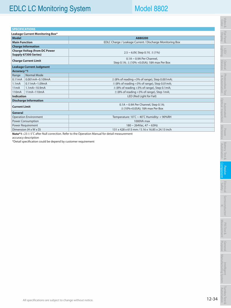
12-34All specifications are subject to change without notice. All specifications are subject to change without notice.
Flat PanelD
isplayPow
er Electronics
Electrical Safety
General
PurposePassive
Component
Semiconductor/
ICBattery Test & Autom
ationAutom
atedO
ptical Inspection Photovoltaic Test
& Automation
PXI Test &
Measurem
ent Video & Color
LED/
LightingO
ptical D
evicesIntelligent
Manufacturing System
Turnkey Test & Autom
ation
Leakage Current Monitoring Box*Model A880200Main Function EDLC Charge / Leakage Current / Discharge Monitoring BoxCharge InformationCharge Voltag (from DC PowerSupply 67300 Series)
2.5 ~ 6.0V, Step 0.1V, ±(1%)
Charge Current Limit0.1A ~ 0.9A Per Channel,
Step 0.1A; ±(10% +0.05A); 18A max Per BoxLeakage Current JudgmentAccuracy *1Range Normal Mode0.11mA 0.001mA~0.109mA ±(8% of reading +3% of range), Step 0.001mA;1.1mA 0.11mA~1.09mA ±(8% of reading +3% of range), Step 0.01mA;11mA 1.1mA~10.9mA ±(8% of reading +3% of range), Step 0.1mA;110mA 11mA~110mA ±(8% of reading +3% of range), Step 1mA;Indication LED (Red Light for Fail)Discharge Information
Current Limit0.1A ~ 0.9A Per Channel, Step 0.1A; ±(10%+0.05A); 18A max Per Box
GeneralOperation Environment Temperature: 10˚C ~ 40˚C Humidity: < 90%RHPower Consumption 1000VA maxPower Requirement 180 ~ 264Vac, 47 ~ 63HzDimension (H x W x D) 131 x 428 x 613 mm / 5.16 x 16.85 x 24.13 inchNote*1 : 23±5˚C after Null correction. Refer to the Operation Manual for detail measurement accuracy description*Detail specification could be depend by customer requirement
SPECIFICATIONS
EDLC LC Monitoring System Model 8802
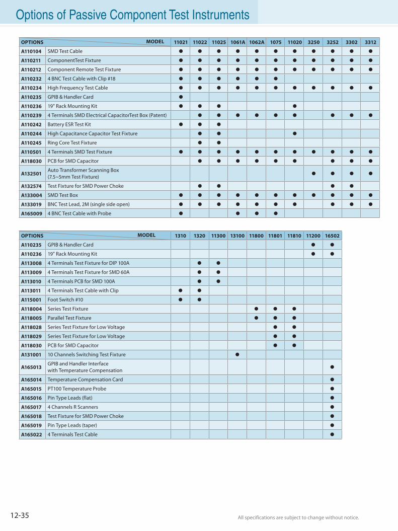
12-35 All specifications are subject to change without notice. All specifications are subject to change without notice.
Options of Passive Component Test Instruments
OPTIONS MODEL 11021 11022 11025 1061A 1062A 1075 11020 3250 3252 3302 3312
A110104 SMD Test Cable
A110211 ComponentTest Fixture
A110212 Component Remote Test Fixture
A110232 4 BNC Test Cable with Clip #18
A110234 High Frequency Test Cable
A110235 GPIB & Handler Card
A110236 19" Rack Mounting Kit
A110239 4 Terminals SMD Electrical CapacitorTest Box (Patent)
A110242 Battery ESR Test Kit
A110244 High Capacitance Capacitor Test Fixture
A110245 Ring Core Test Fixture
A110501 4 Terminals SMD Test Fixture
A118030 PCB for SMD Capacitor
A132501 Auto Transformer Scanning Box(7.5~5mm Test Fixture)
A132574 Test Fixture for SMD Power Choke
A133004 SMD Test Box
A133019 BNC Test Lead, 2M (single side open)
A165009 4 BNC Test Cable with Probe
OPTIONS MODEL 1310 1320 11300 13100 11800 11801 11810 11200 16502
A110235 GPIB & Handler Card
A110236 19" Rack Mounting Kit
A113008 4 Terminals Test Fixture for DIP 100A
A113009 4 Terminals Test Fixture for SMD 60A
A113010 4 Terminals PCB for SMD 100A
A113011 4 Terminals Test Cable with Clip
A115001 Foot Switch #10
A118004 Series Test Fixture
A118005 Parallel Test Fixture
A118028 Series Test Fixture for Low Voltage
A118029 Series Test Fixture for Low Voltage
A118030 PCB for SMD Capacitor
A131001 10 Channels Switching Test Fixture
A165013 GPIB and Handler Interfacewith Temperature Compensation
A165014 Temperature Compensation Card
A165015 PT100 Temperature Probe
A165016 Pin Type Leads (flat)
A165017 4 Channels R Scanners
A165018 Test Fixture for SMD Power Choke
A165019 Pin Type Leads (taper)
A165022 4 Terminals Test Cable
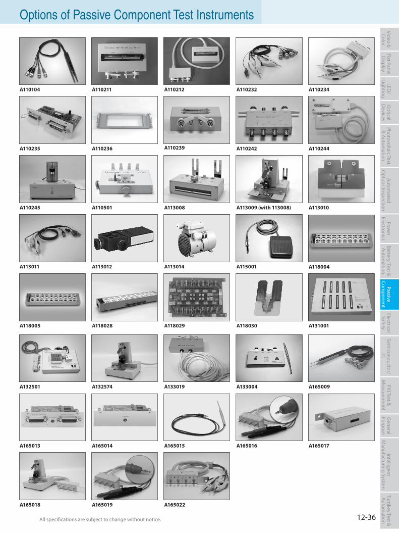
12-36All specifications are subject to change without notice. All specifications are subject to change without notice.
Flat PanelD
isplayPow
er Electronics
Electrical Safety
General
PurposePassive
Component
Semiconductor/
ICBattery Test & Autom
ationAutom
atedO
ptical Inspection Photovoltaic Test
& Automation
PXI Test &
Measurem
ent Video & Color
LED/
LightingO
ptical D
evicesIntelligent
Manufacturing System
Turnkey Test & Autom
ation Options of Passive Component Test Instruments
A110211 A110212 A110234A110104
A113010A113008
A115001 A118004
A118005
A113009 (with 113008)
A110232
A110235 A110236 A110242A110239
A133004
A110244
A110245
A165009
A165013 A165015A165014
A131001
A113011
A165016
A113012
A165022
A165017
A165019A165018
A113014
A118030A118028
A132501 A133019A132574
A118029
A110501
Selection Guides 13-1
Multi-function Electrical Analyzer 13-3
Hipot Tester 13-9
Impulse Winding Tester 13-14
Electrical Safety Test Scanner 13-17
Ground Bond Tester 13-19
Calibrator 13-20
Automatic Test System 13-21
Options of Electrical Safety Test Instruments 13-24
Electrical Safety Test Solution
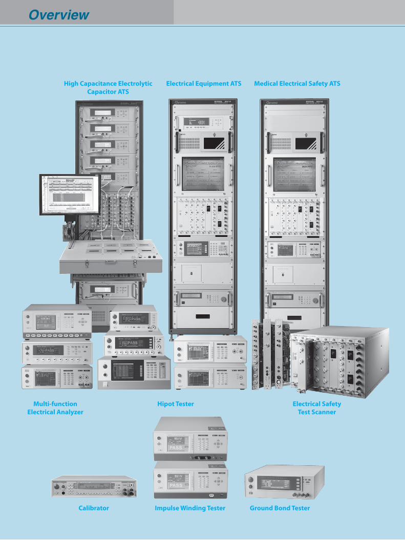
Overview
Multi-function Electrical Analyzer
Calibrator Ground Bond TesterImpulse Winding Tester
Hipot Tester Electrical SafetyTest Scanner
Electrical Equipment ATS Medical Electrical Safety ATSHigh Capacitance ElectrolyticCapacitor ATS
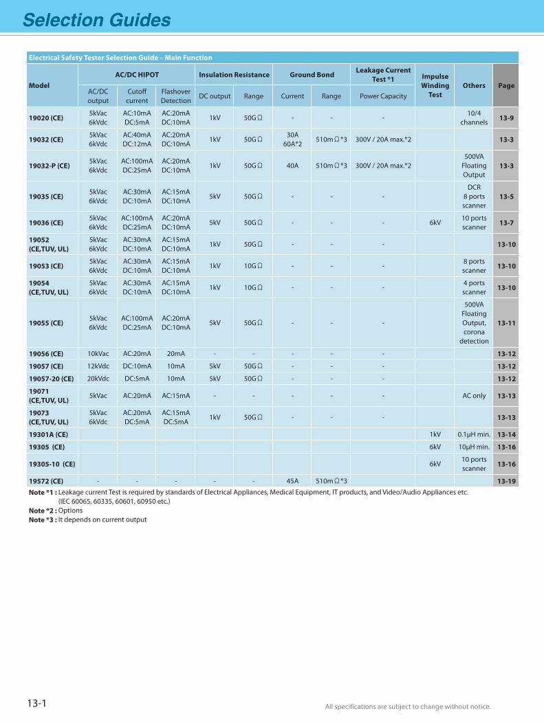
Selection Guides
All specifications are subject to change without notice. All specifications are subject to change without notice.13-1
Electrical Safety Tester Selection Guide – Main Function
ModelAC/DC HIPOT Insulation Resistance Ground Bond
Leakage Current Test *1 Impulse
Winding Test
Others PageAC/DC output
Cutoff current
Flashover Detection
DC output Range Current Range Power Capacity
19020 (CE)5kVac6kVdc
AC:10mADC:5mA
AC:20mADC:10mA
1kV 50GΩ - - -10/4
channels 13-9
19032 (CE)5kVac 6kVdc
AC:40mADC:12mA
AC:20mADC:10mA
1kV 50GΩ30A
60A*2510mΩ*3 300V / 20A max.*2 13-3
19032-P (CE)5kVac 6kVdc
AC:100mADC:25mA
AC:20mADC:10mA
1kV 50GΩ 40A 510mΩ*3 300V / 20A max.*2500VA
Floating Output
13-3
19035 (CE)5kVac 6kVdc
AC:30mADC:10mA
AC:15mADC:10mA
5kV 50GΩ - - -DCR
8 ports scanner
13-5
19036 (CE)5kVac 6kVdc
AC:100mADC:25mA
AC:20mADC:10mA
5kV 50GΩ - - - 6kV10 portsscanner 13-7
19052(CE,TUV, UL)
5kVac 6kVdc
AC:30mADC:10mA
AC:15mADC:10mA
1kV 50GΩ - - - 13-10
19053 (CE)5kVac 6kVdc
AC:30mADC:10mA
AC:15mADC:10mA
1kV 10GΩ - - -8 ports scanner 13-10
19054(CE,TUV, UL)
5kVac 6kVdc
AC:30mADC:10mA
AC:15mADC:10mA
1kV 10GΩ - - -4 ports scanner 13-10
19055 (CE)5kVac6kVdc
AC:100mADC:25mA
AC:20mADC:10mA
5kV 50GΩ - - -
500VAFloating Output,corona
detection
13-11
19056 (CE) 10kVac AC:20mA 20mA - - - - - 13-12
19057 (CE) 12kVdc DC:10mA 10mA 5kV 50GΩ - - - 13-12
19057-20 (CE) 20kVdc DC:5mA 10mA 5kV 50GΩ - - - 13-12
19071(CE,TUV, UL)
5kVac AC:20mA AC:15mA - - - - - AC only 13-13
19073(CE,TUV, UL)
5kVac6kVdc
AC:20mADC:5mA
AC:15mADC:5mA
1kV 50GΩ - - - 13-13
19301A (CE) 1kV 0.1µH min. 13-14
19305 (CE) 6kV 10µH min. 13-16
19305-10 (CE) 6kV10 ports scanner 13-16
19572 (CE) - - - - - 45A 510mΩ*3 13-19Note *1 : Leakage current Test is required by standards of Electrical Appliances, Medical Equipment, IT products, and Video/Audio Appliances etc. (IEC 60065, 60335, 60601, 60950 etc.)Note *2 : OptionsNote *3 : It depends on current output
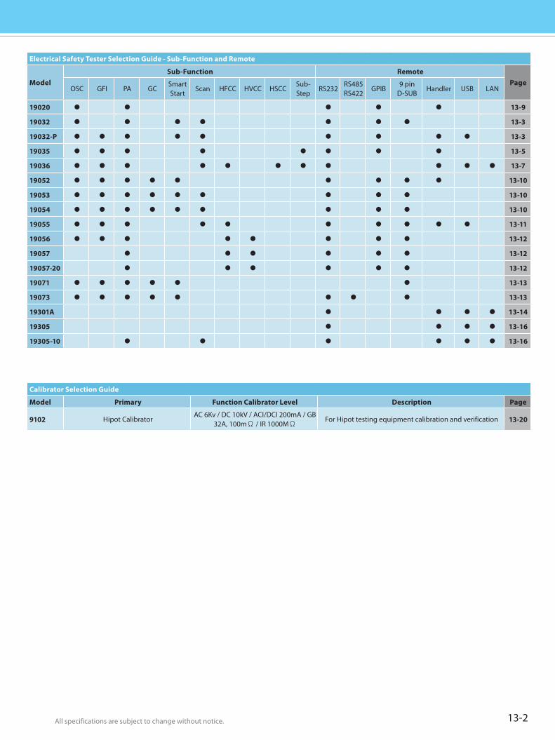
All specifications are subject to change without notice. All specifications are subject to change without notice. 13-2
Calibrator Selection Guide
Model Primary Function Calibrator Level Description Page
9102 Hipot CalibratorAC 6Kv / DC 10kV / ACI/DCI 200mA / GB
32A, 100mΩ / IR 1000MΩFor Hipot testing equipment calibration and verification 13-20
Electrical Safety Tester Selection Guide - Sub-Function and Remote
ModelSub-Function Remote
PageOSC GFI PA GC
SmartStart
Scan HFCC HVCC HSCCSub-Step
RS232RS485RS422
GPIB9 pin
D-SUBHandler USB LAN
19020 13-9
19032 13-3
19032-P 13-3
19035 13-5
19036 13-7
19052 13-10
19053 13-10
19054 13-10
19055 13-11
19056 13-12
19057 13-12
19057-20 13-12
19071 13-13
19073 13-13
19301A 13-14
19305 13-16
19305-10 13-16
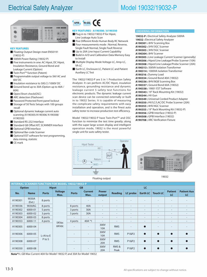
13-3 All specifications are subject to change without notice. All specifications are subject to change without notice.
KEY FEATURES Floating Output Design meet EN50191
(19032-P) 500VA Power Rating (19032-P) Five instruments in one: AC Hipot, DC Hipot,
Insulation Resistance, Ground Bond and Leakage Current (Option)
Twin-PortTM function (Patent) Programmable output voltage to 5kV AC and
6kV DC Insulation resistance to 50GΩ/1000V DC Ground bond up to 30A (Option up to 40A /
60A) Open/Short check(OSC) ARC detection (Flashover) Password Protected front panel lockout Storage of 50 Tests Setups with 100 groups
recall Optional dynamic leakage current auto
scanning (A190305/A190306/ A190308/A190350)
Standard RS-232 Interface Standard GB Offset KIT, SCANNER Interface Optional GPIB Interface Optional Bar-code Scanner Optional EST software for test programming, data mining, statistic CE mark
19032-P : Electrical Safety Analyzer 500VA19032 : Electrical Safety AnalyzerA190301 : 8HV Scanning BoxA190302 : 5HV/3GC ScannerA190303 : 3HV/5GC ScannerA190304 : 8HV ScannerA190305 : Line Leakage Current Scanner (generally)A190306 : Hipot/Line Leakage/Probe Scanner (10A)A190308 : Hipot/Line Leakage/Probe Scanner (20A)A190313 : 500VA Isolation TransformerA190314 : 1000VA Isolation TransformerA190316 : Dummy LoadA190334 : Ground Bond 40A (19032)A190336 : 8HV/8GB Scanning BoxA190337 : Ground Bond 60A (19032)A190338 : 19001 EST SoftwareA190343 : 19" Rack Mounting Kit (19032)A190344 : HV GunA190349 : Universal Corded Product AdapterA190350 : HV/LC/LAC/DC Probe Scanner (20A)A190353 : 4HV/4GC ScannerA190355 : 19" Rack Mounting Kit (19032-P)A190356 : GPIB Interface (19032-P)A190508 : GPIB Interface (19032)A190708 : ARC Verification Fixture
KEY FEATURES - A190308 / A190350 Plug in to 19032/19032-P for Hipot, Line Leakage Auto Scan Five Different Kinds Human Body RC Network Four measurements mode : Normal, Reverse,
Single Fault Normal, Single Fault Reverse Up to 20A Line Input Current Capability Build in A/D and Calibration Data Memory Easy
to Install Multiple Display Mode Voltage-LC, Amp-LC,
VA-LC Earth LC, Enclosure LC, Patient LC and Patient
Auxiliary LC Test
The 19032/19032-P are 5 in 1 Production Safety Analyzer. It can perform AC/DC Hipot, insulation resistance, grounding resistance and dynamic leakage current 5 safety test functions for electronic products. The dynamic leakage current scan device can be connected externally or built in to 19032 Series. It is capable of measuring the complicate safety requirements with easy installation and operation, and is the finest auto safety tester to increase production test efficiency.
Model 19032/19032-P have Twin-PortTM and OSC function to minimize the test time greatly; along with the super large screen display and intelligent operation mode, 19032 is the most powerful single unit for auto safety tester.
Electrical Safety Analyzer Model 19032/19032-P
INTERNAL SCANNER FUNCTION FOR MODEL 19032/19032-POption Hipot GB LC
No. Name PortsVoltage
Max.Ports
Current Max.
Power output
Reading LC probe Earth LC Touch LCPatient
LCPatient Aux
LC
A1903019030A (Ext.)
8 ports
5KVac6KVdc
- - - - - - - - -
A190336 9030AG 8 ports 8 ports 40A - - - - - - -A190302 6000-01 5 ports 3 ports 30A - - - - - - -A190303 6000-02 3 ports 5 ports 30A - - - - - - -A190304 6000-03 8 ports - - - - - - - - -A190353 6000-11 4 ports 4 ports 40A *1 - - - - - - -
A190305 6000-04
L+N to EP to S
- -300V10A
RMS - - - -
A190306 6000-05 - -300V10A
RMS P1&P2
A190308 6000-07 - -300V20A
RMS P1&P2
A190350 6000-08 - -300V20A
RMS & Peak
P1&P2
Note*1 : GB Max Current 40A for Model 19032-P, and 30A for Model 19032
ORDERING INFORMATION
19032Floating output
AHi-Z
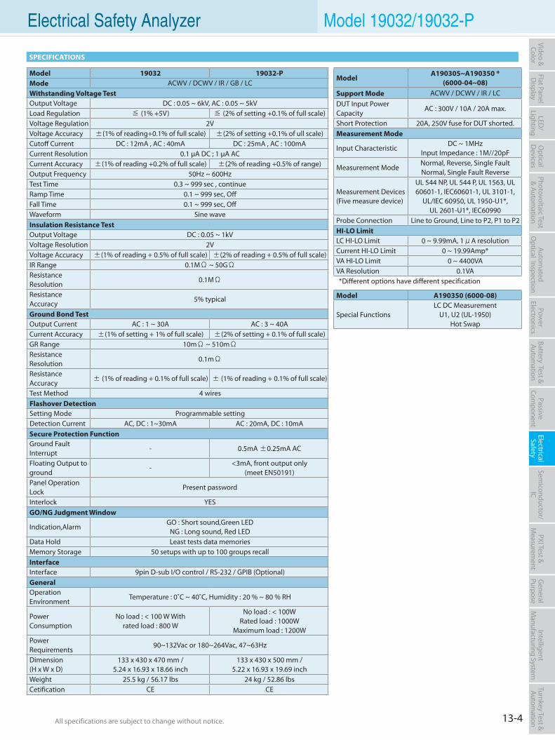
13-4All specifications are subject to change without notice. All specifications are subject to change without notice.
Flat PanelD
isplayPow
er Electronics
Electrical Safety
General
PurposePassive
Component
Semiconductor/
ICBattery Test & Autom
ationAutom
atedO
ptical Inspection Photovoltaic Test
& Automation
PXI Test &
Measurem
ent Video & Color
LED/
LightingO
ptical D
evicesIntelligent
Manufacturing System
Turnkey Test & Autom
ation Electrical Safety Analyzer Model 19032/19032-P
ModelA190305~A190350 *
(6000-04~08)Support Mode ACWV / DCWV / IR / LCDUT Input Power Capacity
AC : 300V / 10A / 20A max.
Short Protection 20A, 250V fuse for DUT shorted.Measurement Mode
Input CharacteristicDC ~ 1MHz
Input Impedance : 1M//20pF
Measurement ModeNormal, Reverse, Single Fault Normal, Single Fault Reverse
Measurement Devices(Five measure device)
UL 544 NP, UL 544 P, UL 1563, UL 60601-1, IEC60601-1, UL 3101-1,
UL/IEC 60950, UL 1950-U1*, UL 2601-U1*, IEC60990
Probe Connection Line to Ground, Line to P2, P1 to P2HI-LO LimitLC HI-LO Limit 0 ~ 9.99mA, 1μA resolutionCurrent HI-LO Limit 0 ~ 19.99Amp*VA HI-LO Limit 0 ~ 4400VAVA Resolution 0.1VA*Different options have different specification
Model A190350 (6000-08)
Special FunctionsLC DC Measurement
U1, U2 (UL-1950)Hot Swap
SPECIFICATIONS
Model 19032 19032-PMode ACWV / DCWV / IR / GB / LCWithstanding Voltage TestOutput Voltage DC : 0.05 ~ 6kV, AC : 0.05 ~ 5kVLoad Regulation ≦ (1% +5V) ≦ (2% of setting +0.1% of full scale)Voltage Regulation 2VVoltage Accuracy ±(1% of reading+0.1% of full scale) ±(2% of setting +0.1% of ull scale)Cutoff Current DC : 12mA , AC : 40mA DC : 25mA , AC : 100mACurrent Resolution 0.1 µA DC ; 1 µA ACCurrent Accuracy ±(1% of reading +0.2% of full scale) ±(2% of reading +0.5% of range)Output Frequency 50Hz ~ 600HzTest Time 0.3 ~ 999 sec , continueRamp Time 0.1 ~ 999 sec, OffFall Time 0.1 ~ 999 sec, OffWaveform Sine waveInsulation Resistance TestOutput Voltage DC : 0.05 ~ 1kVVoltage Resolution 2VVoltage Accuracy ±(1% of reading + 0.5% of full scale) ±(2% of reading + 0.5% of full scale)IR Range 0.1MΩ ~ 50GΩResistance Resolution
0.1MΩ
Resistance Accuracy
5% typical
Ground Bond TestOutput Current AC : 1 ~ 30A AC : 3 ~ 40ACurrent Accuracy ±(1% of setting + 1% of full scale) ±(2% of setting + 0.1% of full scale)GR Range 10mΩ ~ 510mΩResistance Resolution
0.1mΩ
Resistance Accuracy ± (1% of reading + 0.1% of full scale) ± (1% of reading + 0.1% of full scale)
Test Method 4 wiresFlashover DetectionSetting Mode Programmable settingDetection Current AC, DC : 1~30mA AC : 20mA, DC : 10mASecure Protection FunctionGround Fault Interrupt
- 0.5mA ±0.25mA AC
Floating Output to ground
-<3mA, front output only
(meet EN50191)Panel Operation Lock
Present password
Interlock YESGO/NG Judgment Window
Indication,AlarmGO : Short sound,Green LED
NG : Long sound, Red LEDData Hold Least tests data memoriesMemory Storage 50 setups with up to 100 groups recallInterfaceInterface 9pin D-sub I/O control / RS-232 / GPIB (Optional)GeneralOperation Environment
Temperature : 0˚C ~ 40˚C, Humidity : 20 % ~ 80 % RH
Power Consumption
No load : < 100 W Withrated load : 800 W
No load : < 100WRated load : 1000W
Maximum load : 1200WPower Requirements
90~132Vac or 180~264Vac, 47~63Hz
Dimension(H x W x D)
133 x 430 x 470 mm /5.24 x 16.93 x 18.66 inch
133 x 430 x 500 mm /5.22 x 16.93 x 19.69 inch
Weight 25.5 kg / 56.17 lbs 24 kg / 52.86 lbsCetification CE CE
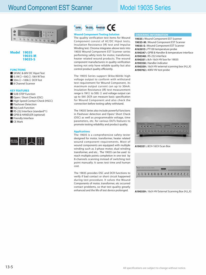
13-5 All specifications are subject to change without notice. All specifications are subject to change without notice.
Wound Component EST Scanner Model 19035 Series
Model 19035 19035-M 19035-S
FUNCTIONS 5KVAC & 6KV DC Hipot Test 0.1MΩ~50GΩ /5kV IR Test 50mΩ~100kΩ DCR Test 8 Channel Scanner
KEY FEATURES SUB-STEP Function Open / Short Check (OSC) High Speed Contact Check (HSCC) Flashover Detection Key Lock Function RS-232 Interface (standard*1) GPIB & HANDLER (optional) Friendly Interface CE Mark
Wound Component Testing Solution The quality verification test items for Wound Component consist of AC/DC Hipot tests, Insulation Resistance (IR) test and Impulse Winding test. Chroma integrates above tests into 19035 Wound Component EST Scanner series performing safety tests for motor, transformer, heater related wound products. The wound component manufacturers in quality verification testing not only have reliable quality but also control product quality efficiently.
The 19035 Series support 5kVac/6kVdc high voltage output to conform with withstand test requirement for Wound Component, its maximum output current can up to 30mA. Insulation Resistance (IR) test measurement range is 1MΩ to 50G Ω and voltage output can up to 5kV. DCR can measure basic specification for Wound Component and also check the connection before testing safety withstand.
The 19035 Series also include powerful functions in Flashover detection and Open/ Short Check (OSC) as well as programmable voltage, time parameters, etc. for various DUTs features to promote testing reliability and product quality.
ApplicationsThe 19035 is a comprehensive safety tester designed for motor, transformer, heater related wound component requirements. Most of wound components are equipped with multiple winding such as 3-phase motor, dual winding transformer, and etc.. The 19035 can be used to reach multiple points completion in one test by 8-channels scanning instead of switching test point manually. It saves test time and human cost.
The 19035 provides OSC and DCR functions to verify if bad contact or short circuit happened during test procedure. It solves the Wound Components of motor, transformer, etc occurred contact problems, so that test quality greatly enhanced and the life of test device prolonged.
ORDERING INFORMATION
A190351 : 8CH-16CH Scan Box
19035 : Wound Component EST Scanner19035-M : Wound Component EST Scanner19035-S : Wound Component EST ScannerA165015 : PT100 temperature probeA190347 : GPIB & Handler & temperature interfaceA190348 : RS-232 interfaceA190351 : 8ch-16ch HV box for 19035A190358 : Handler indicatorA190359 : 16ch HV external scanning box (H,L,X)A190702 : 40KV HV test probe
A190359 : 16ch HV External Scanning Box (H,L,X)
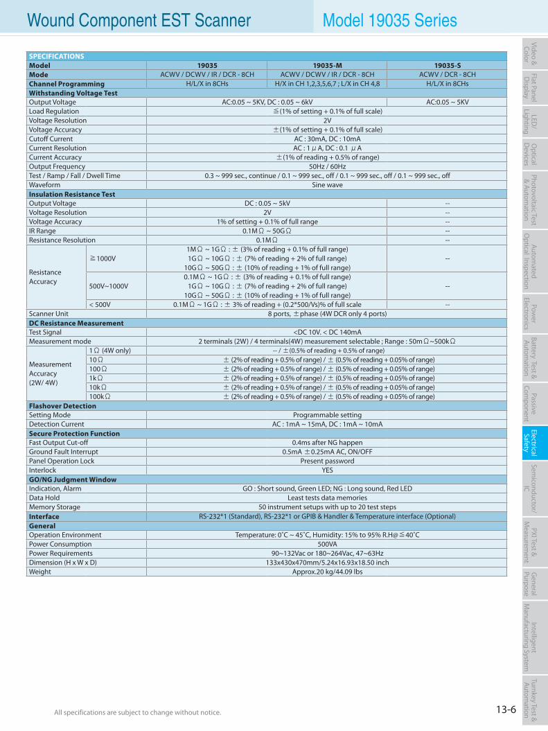
13-6All specifications are subject to change without notice. All specifications are subject to change without notice.
Flat PanelD
isplayPow
er Electronics
Electrical Safety
General
PurposePassive
Component
Semiconductor/
ICBattery Test & Autom
ationAutom
atedO
ptical Inspection Photovoltaic Test
& Automation
PXI Test &
Measurem
ent Video & Color
LED/
LightingO
ptical D
evicesIntelligent
Manufacturing System
Turnkey Test & Autom
ation Wound Component EST Scanner Model 19035 Series
SPECIFICATIONSModel 19035 19035-M 19035-SMode ACWV / DCWV / IR / DCR - 8CH ACWV / DCWV / IR / DCR - 8CH ACWV / DCR - 8CHChannel Programming H/L/X in 8CHs H/X in CH 1,2,3,5,6,7 ; L/X in CH 4,8 H/L/X in 8CHsWithstanding Voltage TestOutput Voltage AC:0.05 ~ 5KV, DC : 0.05 ~ 6kV AC:0.05 ~ 5KVLoad Regulation ≦(1% of setting + 0.1% of full scale)Voltage Resolution 2VVoltage Accuracy ±(1% of setting + 0.1% of full scale)Cutoff Current AC : 30mA, DC : 10mACurrent Resolution AC : 1μA, DC : 0.1 μACurrent Accuracy ±(1% of reading + 0.5% of range)Output Frequency 50Hz / 60HzTest / Ramp / Fall / Dwell Time 0.3 ~ 999 sec., continue / 0.1 ~ 999 sec., off / 0.1 ~ 999 sec., off / 0.1 ~ 999 sec., offWaveform Sine waveInsulation Resistance TestOutput Voltage DC : 0.05 ~ 5kV --Voltage Resolution 2V --Voltage Accuracy 1% of setting + 0.1% of full range --IR Range 0.1MΩ ~ 50GΩ --Resistance Resolution 0.1MΩ --
Resistance Accuracy
≧1000V1MΩ ~ 1GΩ : ± (3% of reading + 0.1% of full range)1GΩ ~ 10GΩ : ± (7% of reading + 2% of full range)
10GΩ ~ 50GΩ : ± (10% of reading + 1% of full range) --
500V~1000V0.1MΩ ~ 1GΩ : ± (3% of reading + 0.1% of full range)
1GΩ ~ 10GΩ : ± (7% of reading + 2% of full range) 10GΩ ~ 50GΩ : ± (10% of reading + 1% of full range)
--
< 500V 0.1MΩ ~ 1GΩ : ± 3% of reading + (0.2*500/Vs)% of full scale --Scanner Unit 8 ports, ±phase (4W DCR only 4 ports)DC Resistance MeasurementTest Signal <DC 10V. < DC 140mAMeasurement mode 2 terminals (2W) / 4 terminals(4W) measurement selectable ; Range : 50mΩ~500kΩ
Measurement Accuracy(2W/ 4W)
1Ω (4W only) -- / ±(0.5% of reading + 0.5% of range)10Ω ± (2% of reading + 0.5% of range) / ± (0.5% of reading + 0.05% of range)100Ω ± (2% of reading + 0.5% of range) / ± (0.5% of reading + 0.05% of range)1kΩ ± (2% of reading + 0.5% of range) / ± (0.5% of reading + 0.05% of range)10kΩ ± (2% of reading + 0.5% of range) / ± (0.5% of reading + 0.05% of range)100kΩ ± (2% of reading + 0.5% of range) / ± (0.5% of reading + 0.05% of range)
Flashover DetectionSetting Mode Programmable settingDetection Current AC : 1mA ~ 15mA, DC : 1mA ~ 10mASecure Protection FunctionFast Output Cut-off 0.4ms after NG happenGround Fault Interrupt 0.5mA ±0.25mA AC, ON/OFFPanel Operation Lock Present passwordInterlock YESGO/NG Judgment WindowIndication, Alarm GO : Short sound, Green LED; NG : Long sound, Red LEDData Hold Least tests data memoriesMemory Storage 50 instrument setups with up to 20 test stepsInterface RS-232*1 (Standard), RS-232*1 or GPIB & Handler & Temperature interface (Optional)GeneralOperation Environment Temperature: 0˚C ~ 45˚C, Humidity: 15% to 95% R.H@≦40˚CPower Consumption 500VAPower Requirements 90~132Vac or 180~264Vac, 47~63HzDimension (H x W x D) 133x430x470mm/5.24x16.93x18.50 inchWeight Approx.20 kg/44.09 lbs
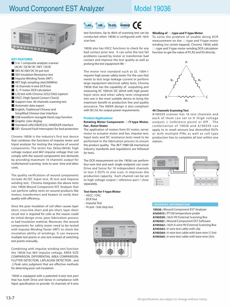
13-7 All specifications are subject to change without notice. All specifications are subject to change without notice.
Wound Component EST Analyzer Model 19036
KEY FEATURES 5 in 1 composite analyzer scanner (ACW / DCW/ IR / IWT / DCR) 5kV AC/6kV DC Hi-pot test 5kV Insulation Resistance test Impulse Winding Tester (IWT) IWT high sampling rate(200MHz) 10 channels 4-wire DCR test Δ /Y motor DCR calculation L/Q test with Chroma 3252/3302 (option) HSCC (High Speed Contact Check) Support max. 40 channels scanning test Automatic data export English, Traditional Chinese and Simplified Chinese User Interface USB waveform storage& Hand copy function Graphic color display Standard LAN,USB,RS232, HANDLER interface GFI (Ground Fault Interrupter) for bod protection
Chroma 19036 is the industry's first test device that combines the functions of impulse tester and hipot analyzer for testing the impulse of wound components. The tester has 5kVac/6kVdc high voltage output and 6kV impulse voltage that can comply with the wound components test demands by providing maximum 10 channels output for multichannel scanning tests to save time and labor costs.
The quality verifications of wound components include AC/DC hipot test, IR test and impulse winding test. Chroma integrates the above tests into 19036 Wound Component EST Analyzer that can perform safety tests on wound products like motors, transformers and heaters to verify their quality with efficiency.
Since the poor insulation of coil often causes layer short, cross-line short and pin short, layer short circuit test is required for coils as the reason could be initial design error, poor fabrication process or bad insulation material. Moreover, the wound components for safety tester need to be tested with Impulse Winding Tester (IWT) to check the insulation ability of windings. It can measure multiple test points in one test instead of switching test points manually.
Combining with impulse winding test function the 19036 has 6kV impulse voltage, AREA SIZE COMPARISON, DIFFERENTIAL AREA COMPARISON, FLUTTER DETECTION, LAPLACIAN DETECTION , and ΔPeak ratio judgment that are effective methods for detecting poor coil insulation.
19036 is equipped with a patented 4-wire test port that has both Drive and Sense in compliance with hipot specification to provide 10 channels of 4-wire
test functions. Up to 40ch of scanning test can be conducted when 19036 is configured with 16ch scan box.
19036 also has HSCC functions to check for any bad contact prior test. It can solve the test fail problems caused by motor or transformer bad contact and improve the test quality as well as prolong the test equipment life。
The motor test standard such as UL 1004-1 requires high power safety tester. For the user that needs to test large leakage current or perform large equipment electrical safety tests, Chroma 19036 that has the capability of outputting and measuring AC 100mA/ DC 20mA with high power hipot tests and other safety tests integrated into one is the most suitable device to bring the maximum benefit to production line and quality assurance. The 500VA design is also compliant with IEC/UL for output power requirements.
Product ApplicationsRotating Motor Component: /Y-type Motor, Fan , Rotor/Stator The application of motors from EV motor, server motor to actuator motor and fan, impulse test, hipot tests and DC resistance tests need to be performed in the fabrication process to ensure the product quality. The JB/T 7080 GB mechanical industry standards and regulations are followed for tests.
The DCR measurement on the 19036 can perform four-wire test and each single endpoint can cover Drive and Sense for 10 independent channels to test 3 DUTs in one scan. I t improves the production capacity. Each channel can be set to high voltage output / reference port / close separately.
Test Items for Y-type Motor- HSCC / OSC- DCR Test- Impulse Test - Hi-pot –Sub step test
ORDERING INFORMATION
19036 : Wound Component EST Analyzer A165015 : PT100 temperature probeA190359 : 16ch HV External Scanning BoxA190361 : Wound Component EST SoftwareA190362 : 16ch 4-wire HV External Scanning BoxA190363 : 4-wire test cable with clipA190364 : 4-wire test cable with bare wire (1.5m)A190365 : 4-wire test cable with bare wire (3m)
Winding of -type and Y-type MotorTo solve the problem of unable doing DCR measurement on the -type and Y-type motor winding (no center-tapped), Chroma 19036 adds -type and Y-type motor winding DCR calculation function to get the value of R1,R2 and R3 directly.
40 Channels Scanning TestA190359 scanner has 16 test channels and e a c h o f t h e m c a n s e t t o H (h i g h v o l t a g e o u t p u t) , L (r e fe r e n c e p o i n t) o r O f f . T h e c o m b i n a t i o n o f 19036 a n d A190359 c a n apply to in small amount but diversified DUTs o r w i t h m u l t i p l e P I N s a s we l l a s ce l l t y p e production line to complete all test within one station.
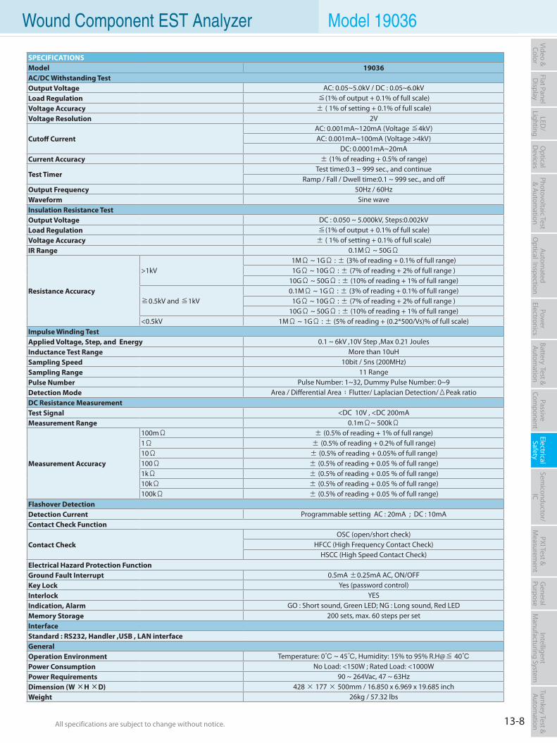
13-8All specifications are subject to change without notice. All specifications are subject to change without notice.
Flat PanelD
isplayPow
er Electronics
Electrical Safety
General
PurposePassive
Component
Semiconductor/
ICBattery Test & Autom
ationAutom
atedO
ptical Inspection Photovoltaic Test
& Automation
PXI Test &
Measurem
ent Video & Color
LED/
LightingO
ptical D
evicesIntelligent
Manufacturing System
Turnkey Test & Autom
ation Wound Component EST Analyzer Model 19036
SPECIFICATIONSModel 19036 AC/DC Withstanding Test Output Voltage AC: 0.05~5.0kV / DC : 0.05~6.0kV Load Regulation ≦(1% of output + 0.1% of full scale)Voltage Accuracy ± ( 1% of setting + 0.1% of full scale)Voltage Resolution 2V
Cutoff CurrentAC: 0.001mA~120mA (Voltage ≦4kV)AC: 0.001mA~100mA (Voltage >4kV)
DC: 0.0001mA~20mACurrent Accuracy ± (1% of reading + 0.5% of range)
Test Timer Test time:0.3 ~ 999 sec., and continue
Ramp / Fall / Dwell time:0.1 ~ 999 sec., and off Output Frequency 50Hz / 60HzWaveform Sine waveInsulation Resistance TestOutput Voltage DC : 0.050 ~ 5.000kV, Steps:0.002kVLoad Regulation ≦(1% of output + 0.1% of full scale)Voltage Accuracy ± ( 1% of setting + 0.1% of full scale)IR Range 0.1MΩ ~ 50GΩ
Resistance Accuracy
>1kV 1MΩ ~ 1GΩ : ± (3% of reading + 0.1% of full range) 1GΩ ~ 10GΩ : ± (7% of reading + 2% of full range )
10GΩ ~ 50GΩ : ± (10% of reading + 1% of full range)
≧0.5kV and ≦1kV 0.1MΩ ~ 1GΩ : ± (3% of reading + 0.1% of full range)
1GΩ ~ 10GΩ : ± (7% of reading + 2% of full range )10GΩ ~ 50GΩ : ± (10% of reading + 1% of full range)
<0.5kV 1MΩ ~ 1GΩ : ± (5% of reading + (0.2*500/Vs)% of full scale) Impulse Winding Test Applied Voltage, Step, and Energy 0.1 ~ 6kV ,10V Step ,Max 0.21 Joules Inductance Test Range More than 10uH Sampling Speed 10bit / 5ns (200MHz)Sampling Range 11 RangePulse Number Pulse Number: 1~32, Dummy Pulse Number: 0~9 Detection Mode Area / Differential Area;Flutter/ Laplacian Detection/ΔPeak ratioDC Resistance Measurement Test Signal <DC 10V , <DC 200mAMeasurement Range 0.1mΩ~ 500kΩ
Measurement Accuracy
100mΩ ± (0.5% of reading + 1% of full range) 1Ω ± (0.5% of reading + 0.2% of full range) 10Ω ± (0.5% of reading + 0.05% of full range) 100Ω ± (0.5% of reading + 0.05 % of full range) 1kΩ ± (0.5% of reading + 0.05 % of full range) 10kΩ ± (0.5% of reading + 0.05 % of full range) 100kΩ ± (0.5% of reading + 0.05 % of full range)
Flashover Detection Detection Current Programmable setting AC : 20mA ; DC : 10mA Contact Check Function
Contact Check OSC (open/short check)
HFCC (High Frequency Contact Check)HSCC (High Speed Contact Check)
Electrical Hazard Protection Function Ground Fault Interrupt 0.5mA ±0.25mA AC, ON/OFFKey Lock Yes (password control)Interlock YESIndication, Alarm GO : Short sound, Green LED; NG : Long sound, Red LEDMemory Storage 200 sets, max. 60 steps per setInterface Standard : RS232, Handler ,USB , LAN interfaceGeneralOperation Environment Temperature: 0 ~ 45, Humidity: 15% to 95% R.H@≦ 40Power Consumption No Load: <150W ; Rated Load: <1000WPower Requirements 90 ~ 264Vac, 47 ~ 63HzDimension (W ×H ×D) 428 × 177 × 500mm / 16.850 x 6.969 x 19.685 inchWeight 26kg / 57.32 lbs
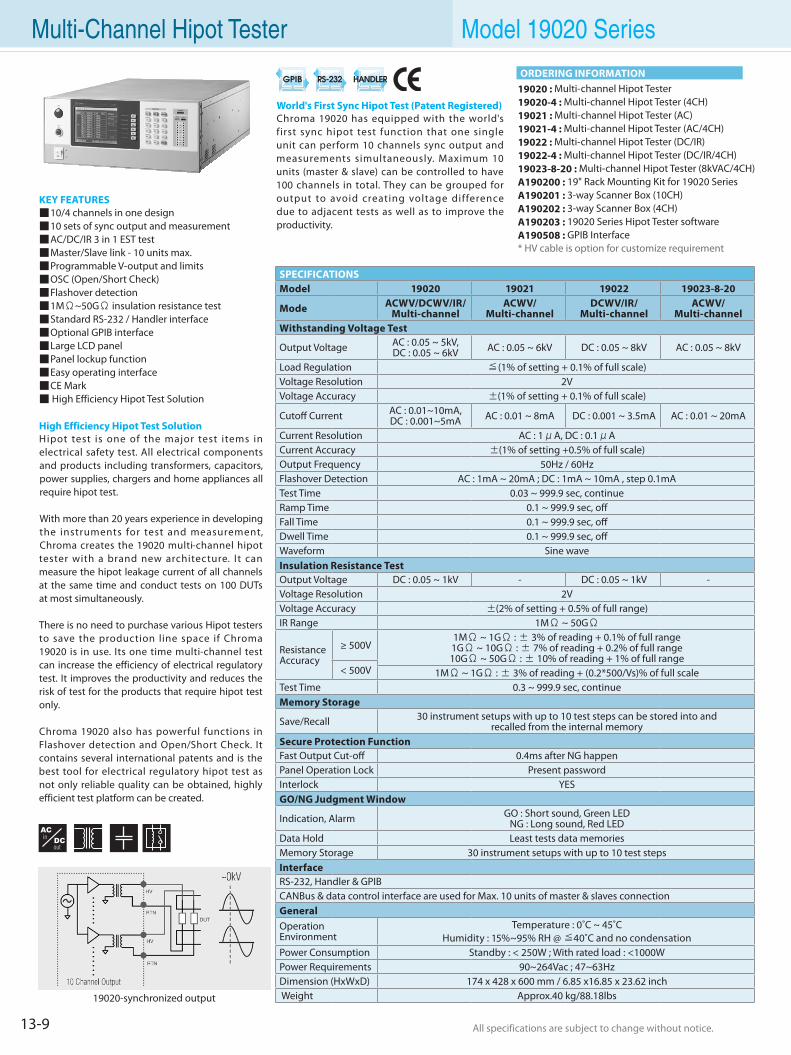
13-9 All specifications are subject to change without notice. All specifications are subject to change without notice.
KEY FEATURES 10/4 channels in one design 10 sets of sync output and measurement AC/DC/IR 3 in 1 EST test Master/Slave link - 10 units max. Programmable V-output and limits OSC (Open/Short Check) Flashover detection 1MΩ~50GΩ insulation resistance test Standard RS-232 / Handler interface Optional GPIB interface Large LCD panel Panel lockup function Easy operating interface CE Mark High Efficiency Hipot Test Solution
High Efficiency Hipot Test SolutionHipot test is one of the major test items in electrical safety test. All electrical components and products including transformers, capacitors, power supplies, chargers and home appliances all require hipot test.
With more than 20 years experience in developing the instruments for test and measurement, Chroma creates the 19020 multi-channel hipot tester with a brand new architecture. It can measure the hipot leakage current of all channels at the same time and conduct tests on 100 DUTs at most simultaneously.
There is no need to purchase various Hipot testers to save the production line space if Chroma 19020 is in use. Its one time multi-channel test can increase the efficiency of electrical regulatory test. It improves the productivity and reduces the risk of test for the products that require hipot test only.
Chroma 19020 also has powerful functions in Flashover detection and Open/Short Check. It contains several international patents and is the best tool for electrical regulatory hipot test as not only reliable quality can be obtained, highly efficient test platform can be created.
19020 : Multi-channel Hipot Tester19020-4 : Multi-channel Hipot Tester (4CH)19021 : Multi-channel Hipot Tester (AC)19021-4 : Multi-channel Hipot Tester (AC/4CH)19022 : Multi-channel Hipot Tester (DC/IR)19022-4 : Multi-channel Hipot Tester (DC/IR/4CH)19023-8-20 : Multi-channel Hipot Tester (8kVAC/4CH)A190200 : 19" Rack Mounting Kit for 19020 SeriesA190201 : 3-way Scanner Box (10CH)A190202 : 3-way Scanner Box (4CH)A190203 : 19020 Series Hipot Tester softwareA190508 : GPIB Interface* HV cable is option for customize requirement
World's First Sync Hipot Test (Patent Registered)Chroma 19020 has equipped with the world's first sync hipot test function that one single unit can perform 10 channels sync output and measurements simultaneously. Maximum 10 units (master & slave) can be controlled to have 100 channels in total. They can be grouped for output to avoid creating voltage difference due to adjacent tests as well as to improve the productivity.
Multi-Channel Hipot Tester Model 19020 Series
ORDERING INFORMATION
19020-synchronized output
SPECIFICATIONSModel 19020 19021 19022 19023-8-20
Mode ACWV/DCWV/IR/Multi-channel
ACWV/Multi-channel
DCWV/IR/Multi-channel
ACWV/Multi-channel
Withstanding Voltage Test
Output Voltage AC : 0.05 ~ 5kV,DC : 0.05 ~ 6kV AC : 0.05 ~ 6kV DC : 0.05 ~ 8kV AC : 0.05 ~ 8kV
Load Regulation ≦(1% of setting + 0.1% of full scale)Voltage Resolution 2V Voltage Accuracy ±(1% of setting + 0.1% of full scale)
Cutoff Current AC : 0.01~10mA, DC : 0.001~5mA AC : 0.01 ~ 8mA DC : 0.001 ~ 3.5mA AC : 0.01 ~ 20mA
Current Resolution AC : 1μA, DC : 0.1μACurrent Accuracy ±(1% of setting +0.5% of full scale)Output Frequency 50Hz / 60HzFlashover Detection AC : 1mA ~ 20mA ; DC : 1mA ~ 10mA , step 0.1mATest Time 0.03 ~ 999.9 sec, continueRamp Time 0.1 ~ 999.9 sec, offFall Time 0.1 ~ 999.9 sec, offDwell Time 0.1 ~ 999.9 sec, offWaveform Sine wave Insulation Resistance TestOutput Voltage DC : 0.05 ~ 1kV - DC : 0.05 ~ 1kV -Voltage Resolution 2VVoltage Accuracy ±(2% of setting + 0.5% of full range)IR Range 1MΩ ~ 50GΩ
ResistanceAccuracy
≥ 500V1MΩ ~ 1GΩ : ± 3% of reading + 0.1% of full range 1GΩ ~ 10GΩ : ± 7% of reading + 0.2% of full range 10GΩ ~ 50GΩ : ± 10% of reading + 1% of full range
< 500V 1MΩ ~ 1GΩ : ± 3% of reading + (0.2*500/Vs)% of full scaleTest Time 0.3 ~ 999.9 sec, continueMemory Storage
Save/Recall 30 instrument setups with up to 10 test steps can be stored into andrecalled from the internal memory
Secure Protection FunctionFast Output Cut-off 0.4ms after NG happenPanel Operation Lock Present passwordInterlock YESGO/NG Judgment Window
Indication, Alarm GO : Short sound, Green LEDNG : Long sound, Red LED
Data Hold Least tests data memoriesMemory Storage 30 instrument setups with up to 10 test stepsInterfaceRS-232, Handler & GPIBCANBus & data control interface are used for Max. 10 units of master & slaves connectionGeneralOperation Environment
Temperature : 0˚C ~ 45˚CHumidity : 15%~95% RH @ ≦40˚C and no condensation
Power Consumption Standby : < 250W ; With rated load : <1000WPower Requirements 90~264Vac ; 47~63HzDimension (HxWxD) 174 x 428 x 600 mm / 6.85 x16.85 x 23.62 inch Weight Approx.40 kg/88.18lbs
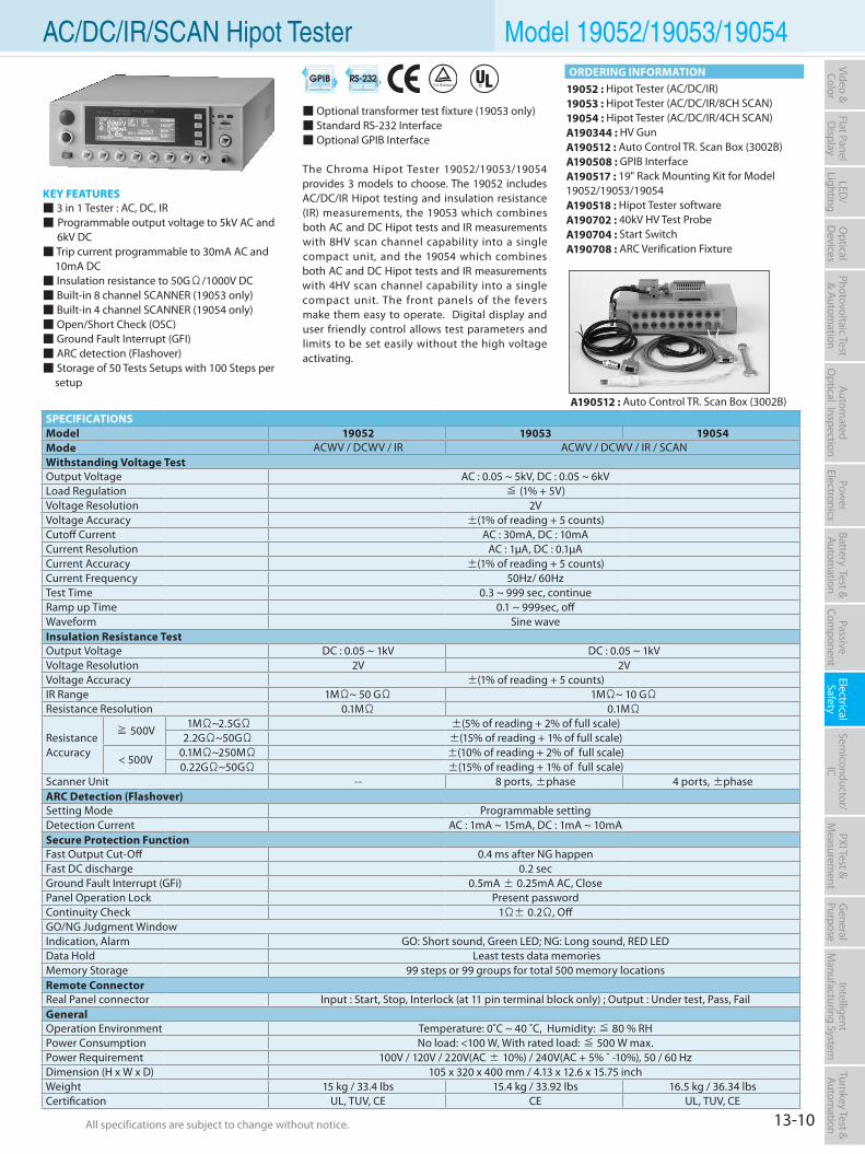
13-10All specifications are subject to change without notice. All specifications are subject to change without notice.
Flat PanelD
isplayPow
er Electronics
Electrical Safety
General
PurposePassive
Component
Semiconductor/
ICBattery Test & Autom
ationAutom
atedO
ptical Inspection Photovoltaic Test
& Automation
PXI Test &
Measurem
ent Video & Color
LED/
LightingO
ptical D
evicesIntelligent
Manufacturing System
Turnkey Test & Autom
ation AC/DC/IR/SCAN Hipot Tester Model 19052/19053/19054
KEY FEATURES 3 in 1 Tester : AC, DC, IR Programmable output voltage to 5kV AC and
6kV DC Trip current programmable to 30mA AC and
10mA DC Insulation resistance to 50GΩ/1000V DC Built-in 8 channel SCANNER (19053 only) Built-in 4 channel SCANNER (19054 only) Open/Short Check (OSC) Ground Fault Interrupt (GFI) ARC detection (Flashover) Storage of 50 Tests Setups with 100 Steps per
setup
19052 : Hipot Tester (AC/DC/IR)19053 : Hipot Tester (AC/DC/IR/8CH SCAN)19054 : Hipot Tester (AC/DC/IR/4CH SCAN)A190344 : HV GunA190512 : Auto Control TR. Scan Box (3002B)A190508 : GPIB InterfaceA190517 : 19" Rack Mounting Kit for Model 19052/19053/19054A190518 : Hipot Tester softwareA190702 : 40kV HV Test ProbeA190704 : Start SwitchA190708 : ARC Verification Fixture
Optional transformer test fixture (19053 only) Standard RS-232 Interface Optional GPIB Interface
The Chroma Hipot Tester 19052/19053/19054 provides 3 models to choose. The 19052 includes AC/DC/IR Hipot testing and insulation resistance (IR) measurements, the 19053 which combines both AC and DC Hipot tests and IR measurements with 8HV scan channel capability into a single compact unit, and the 19054 which combines both AC and DC Hipot tests and IR measurements with 4HV scan channel capability into a single compact unit. The front panels of the fevers make them easy to operate. Digital display and user friendly control allows test parameters and limits to be set easily without the high voltage activating.
A190512 : Auto Control TR. Scan Box (3002B)SPECIFICATIONSModel 19052 19053 19054Mode ACWV / DCWV / IR ACWV / DCWV / IR / SCANWithstanding Voltage Test Output Voltage AC : 0.05 ~ 5kV, DC : 0.05 ~ 6kV Load Regulation ≦ (1% + 5V)Voltage Resolution 2V Voltage Accuracy ±(1% of reading + 5 counts) Cutoff Current AC : 30mA, DC : 10mACurrent Resolution AC : 1µA, DC : 0.1µACurrent Accuracy ±(1% of reading + 5 counts) Current Frequency 50Hz/ 60Hz Test Time 0.3 ~ 999 sec, continueRamp up Time 0.1 ~ 999sec, offWaveform Sine waveInsulation Resistance TestOutput Voltage DC : 0.05 ~ 1kV DC : 0.05 ~ 1kVVoltage Resolution 2V 2VVoltage Accuracy ±(1% of reading + 5 counts) IR Range 1MΩ~ 50 GΩ 1MΩ~ 10 GΩ Resistance Resolution 0.1MΩ 0.1MΩ
ResistanceAccuracy
≧ 500V 1MΩ~2.5GΩ ±(5% of reading + 2% of full scale) 2.2GΩ~50GΩ ±(15% of reading + 1% of full scale)
< 500V 0.1MΩ~250MΩ ±(10% of reading + 2% of full scale) 0.22GΩ~50GΩ ±(15% of reading + 1% of full scale)
Scanner Unit -- 8 ports, ±phase 4 ports, ±phaseARC Detection (Flashover)Setting Mode Programmable settingDetection Current AC : 1mA ~ 15mA, DC : 1mA ~ 10mASecure Protection Function Fast Output Cut-Off 0.4 ms after NG happenFast DC discharge 0.2 sec Ground Fault Interrupt (GFi) 0.5mA ± 0.25mA AC, ClosePanel Operation Lock Present passwordContinuity Check 1Ω± 0.2Ω, OffGO/NG Judgment WindowIndication, Alarm GO: Short sound, Green LED; NG: Long sound, RED LEDData Hold Least tests data memories Memory Storage 99 steps or 99 groups for total 500 memory locationsRemote ConnectorReal Panel connector Input : Start, Stop, Interlock (at 11 pin terminal block only) ; Output : Under test, Pass, FailGeneralOperation Environment Temperature: 0˚C ~ 40 ˚C, Humidity: ≦ 80 % RH Power Consumption No load: <100 W, With rated load: ≦ 500 W max.Power Requirement 100V / 120V / 220V(AC ± 10%) / 240V(AC + 5% ˜ -10%), 50 / 60 Hz Dimension (H x W x D) 105 x 320 x 400 mm / 4.13 x 12.6 x 15.75 inchWeight 15 kg / 33.4 lbs 15.4 kg / 33.92 lbs 16.5 kg / 36.34 lbsCertification UL, TUV, CE CE UL, TUV, CE
ORDERING INFORMATION
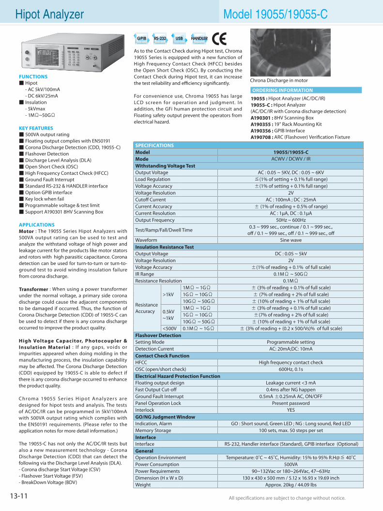
13-11 All specifications are subject to change without notice. All specifications are subject to change without notice.
Hipot Analyzer Model 19055/19055-C
As to the Contact Check during Hipot test, Chroma 19055 Series is equipped with a new function of High Frequency Contact Check (HFCC) besides the Open Short Check (OSC). By conducting the Contact Check during Hipot test, it can increase the test reliability and efficiency significantly.
For convenience use, Chroma 19055 has large LCD screen for operation and judgment. In addition, the GFi human protection circuit and Floating safety output prevent the operators from electrical hazard.
SPECIFICATIONSModel 19055/19055-CMode ACWV / DCWV / IRWithstanding Voltage TestOutput Voltage AC : 0.05 ~ 5KV, DC : 0.05 ~ 6KVLoad Regulation ≦(1% of setting + 0.1% full range)Voltage Accuracy ±(1% of setting + 0.1% full range)Voltage Resolution 2VCutoff Current AC : 100mA ; DC : 25mACurrent Accuracy ± (1% of reading + 0.5% of range)Current Resolution AC : 1µA, DC : 0.1µAOutput Frequency 50Hz ~ 600Hz
Test/Ramp/Fall/Dwell Time0.3 ~ 999 sec., continue / 0.1 ~ 999 sec.,
off / 0.1 ~ 999 sec., off / 0.1 ~ 999 sec., offWaveform Sine waveInsulation Resistance TestOutput Voltage DC : 0.05 ~ 5kVVoltage Resolution 2VVoltage Accuracy ±(1% of reading + 0.1% of full scale)IR Range 0.1MΩ ~ 50GΩResistance Resolution 0.1MΩ
Resistance Accuracy
>1kV1MΩ ~ 1GΩ ± (3% of reading + 0.1% of full scale)1GΩ ~ 10GΩ ± (7% of reading + 2% of full scale)10GΩ ~ 50GΩ ± (10% of reading + 1% of full scale)
0.5kV~1kV
1MΩ ~ 1GΩ ± (3% of reading + 0.1% of full scale)1GΩ ~ 10GΩ ±(7% of reading + 2% of full scale)10GΩ ~ 50GΩ ± (10% of reading + 1% of full scale)
<500V 0.1MΩ ~ 1GΩ ± (3% of reading + (0.2 x 500/Vs)% of full scale)Flashover DetectionSetting Mode Programmable settingDetection Current AC: 20mA;DC: 10mAContact Check FunctionHFCC High frequency contact checkOSC (open/short check) 600Hz, 0.1sElectrical Hazard Protection FunctionFloating output design Leakage current <3 mAFast Output Cut-off 0.4ms after NG happenGround Fault Interrupt 0.5mA ±0.25mA AC, ON/OFFPanel Operation Lock Present passwordInterlock YESGO/NG Judgment WindowIndication, Alarm GO : Short sound, Green LED ; NG : Long sound, Red LEDMemory Storage 100 sets, max. 50 steps per setInterfaceInterface RS-232, Handler interface (Standard), GPIB interface (Optional)GeneralOperation Environment Temperature: 0˚C ~ 45˚C, Humidity: 15% to 95% R.H@≦ 40˚CPower Consumption 500VAPower Requirements 90~132Vac or 180~264Vac, 47~63HzDimension (H x W x D) 130 x 430 x 500 mm / 5.12 x 16.93 x 19.69 inchWeight Approx. 20kg / 44.09 lbs
FUNCTIONS Hipot - AC 5kV/100mA - DC 6kV/25mA Insulation - 5kVmax - 1MΩ~50GΩ
KEY FEATURES 500VA output rating Floating output complies with EN50191 Corona Discharge Detection (CDD, 19055-C) Flashover Detection Discharge Level Analysis (DLA) Open Short Check (OSC) High Frequency Contact Check (HFCC) Ground Fault Interrupt Standard RS-232 & HANDLER interface Option GPIB interface Key lock when fail Programmable voltage & test limit Support A190301 8HV Scanning Box
APPLICATIONSMotor : The 19055 Series Hipot Analyzers with 500VA output rating can be used to test and analyze the withstand voltage of high power and leakage current for the products like motor stators and rotors with high parasitic capacitance. Corona detection can be used for turn-to-turn or turn-to-ground test to avoid winding insulation failure from corona discharge.
Transformer : When using a power transformer under the normal voltage, a primary side corona discharge could cause the adjacent components to be damaged if occurred. Thus, the function of Corona Discharge Detection (CDD) of 19055-C can be used to detect if there is any corona discharge occurred to improve the product quality.
High Voltage Capacitor, Photocoupler & Insulation Material : I f any gaps, voids or impurities appeared when doing molding in the manufacturing process, the insulation capability may be affected. The Corona Discharge Detection (CDD) equipped by 19055-C is able to defect if there is any corona discharge occurred to enhance the product quality.
Chroma 19055 S er ies H ipot Analyzers are designed for hipot tests and analysis. The tests of AC/DC/IR can be programmed in 5kV/100mA with 500VA output rating which complies with the EN50191 requirements. (Please refer to the application notes for more detail information.)
The 19055-C has not only the AC/DC/IR tests but also a new measurement technology - Corona Discharge Detection (CDD) that can detect the following via the Discharge Level Analysis (DLA).- Corona discharge Start Voltage (CSV)- Flashover Start Voltage (FSV)- BreakDown Voltage (BDV)
19055 : Hipot Analyzer (AC/DC/IR)19055-C : Hipot Analyzer(AC/DC/IR with Corona discharge detection)A190301 : 8HV Scanning BoxA190355 : 19" Rack Mounting Kit A190356 : GPIB InterfaceA190708 : ARC (Flashover) Verification Fixture
ORDERING INFORMATION
Chrona Discharge in motor
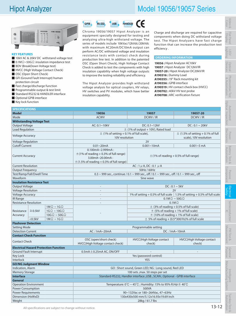
13-12All specifications are subject to change without notice. All specifications are subject to change without notice.
Flat PanelD
isplayPow
er Electronics
Electrical Safety
General
PurposePassive
Component
Semiconductor/
ICBattery Test & Autom
ationAutom
atedO
ptical Inspection Photovoltaic Test
& Automation
PXI Test &
Measurem
ent Video & Color
LED/
LightingO
ptical D
evicesIntelligent
Manufacturing System
Turnkey Test & Autom
ation
KEY FEATURES 10kV AC & 20kV DC withstand voltage test 0.1MΩ~50GΩ insulation impedance test BDV (BreakDown Voltage test) HVCC (High Voltage Contact Check) OSC (Open Short Check) GFI (Ground Fault Interrupt) human protection circuit Fast charge/discharge function Programmable output & test limit Standard RS232 & HANDLER interface Optional GPIB interface Key lock function
19056 : Hipot Analyzer AC10kV19057 : Hipot Analyzer DC12kV/IR19057-20 : Hipot Analyzer DC20kV/IR A190316 : Dummy LoadA190355 : 19" Rack mounting kitA190356 : GPIB interfaceA190519 : HV contact check box (HVCC)A190702 : 40kV HV test probeA190708 : ARC verification fixture
Chroma 19056/19057 Hip ot Analy zer is an equipment specially designed for testing and analyzing ultra-high withstand voltage. The series of models include 10kVac/12kVdc/20kVdc with maximum AC20mA/DC10mA output can perform AC/DC withstand voltage and insulation resistance tests with contact check during production line test. In addition to the patented OSC (Open Short Check), High Voltage Contact Check is added to test the components with high insulation capability when high voltage outputs to improve the testing reliability and efficiency.
The Hipot Analyzer provides high withstand voltage analysis for optical couplers, HV relays, HV switches and PV modules, which have better insulation capability.
Hipot Analyzer Model 19056/19057 Series
ORDERING INFORMATION
SPECIFICATIONSModel 19056 19057 19057-20Mode ACWV DCWV / IR DCWV / IRWithstanding Voltage TestOutput Voltage AC: 0.1~10kV DC: 0.1~12kV DC : 0.1 ~ 20kVLoad Regulation ± (1% of output + 10V), Rated load
Voltage Accuracy ± (1% of setting + 0.1% of full scale), 10V resolution
± (1.5% of setting + 0.1% of full scale), 10V resolution
Voltage Regulation 2VCutoff Current 0.01~20mA 0.001~10mA 0.001~5 mA
Current Accuracy
0.100mA~2.999mA :±(1% of reading + 0.3% of full range)
3.00mA~20.00mA :±(1.5% of reading + 0.3% of full range)
±(1% of reading + 0.5% of full range)
Current Resolution AC : 1μA, DC : 0.1 μAOutput Frequency 50Hz / 60HzTest/Ramp/Fall/Dwell Time 0.3 ~ 999 sec., continue / 0.1 ~ 999 sec., off / 0.1 ~ 999 sec., off / 0.1 ~ 999 sec., offWaveform Sine waveInsulation Resistance TestOutput Voltage - DC : 0.1 ~ 5kVVoltage Resolution - 2VVoltage Accuracy - 1% of setting + 0.5% of full scale 1.5% of setting + 0.5% of full scaleIR Range - 0.1MΩ ~ 50GΩResistance Resolution - 0.1MΩ
Resistance Accuracy
≧0.5kV1MΩ ~ 1GΩ
-
± (3% of reading + 0.5% of full scale)1GΩ ~ 10GΩ ± (5% of reading + 1% of full scale)10GΩ ~ 50GΩ ± (10% of reading + 1% of full scale)
<0.5kV 1MΩ ~ 1GΩ ± 5% of reading + (0.5*300/Vs)% of full scaleFlashover DetectionSetting Mode Programmable settingDetection Current AC : 1mA~20mA DC : 1mA~10mAContact Check Function
Contact CheckOSC (open/short check)
HVCC(High Voltage contact check)HVCC(High Voltage contact
check)HVCC(High Voltage contact
check)Electrical Hazard Protection FunctionGround Fault Interrupt 0.5mA±0.25mA AC, ON/OFF - -Key Lock Yes (password control)Interlock YESGO/NG Judgment WindowIndication, Alarm GO : Short sound, Green LED; NG : Long sound, Red LEDMemory Storage 100 sets ,max. 50 steps per setInterface Standard-RS232, Handler interface ,USB , SCAN ; Optional - GPIB interfaceGeneralOperation Environment Temperature: 0 ~ 45 ; Humidity: 15% to 95% R.H@≦ 40Power Consumption 500VAPower Requirements 90~132Vac or 180~264Vac, 47~63HzDimension (HxWxD) 130x430x500 mm/5.12x16.93x19.69 inchWeight 28kg / 61.7 lbs
Charge and discharge are required for capacitive components when doing DC withstand voltage test. The Hipot Analy zers have fast charge function that can increase the production test efficiency .
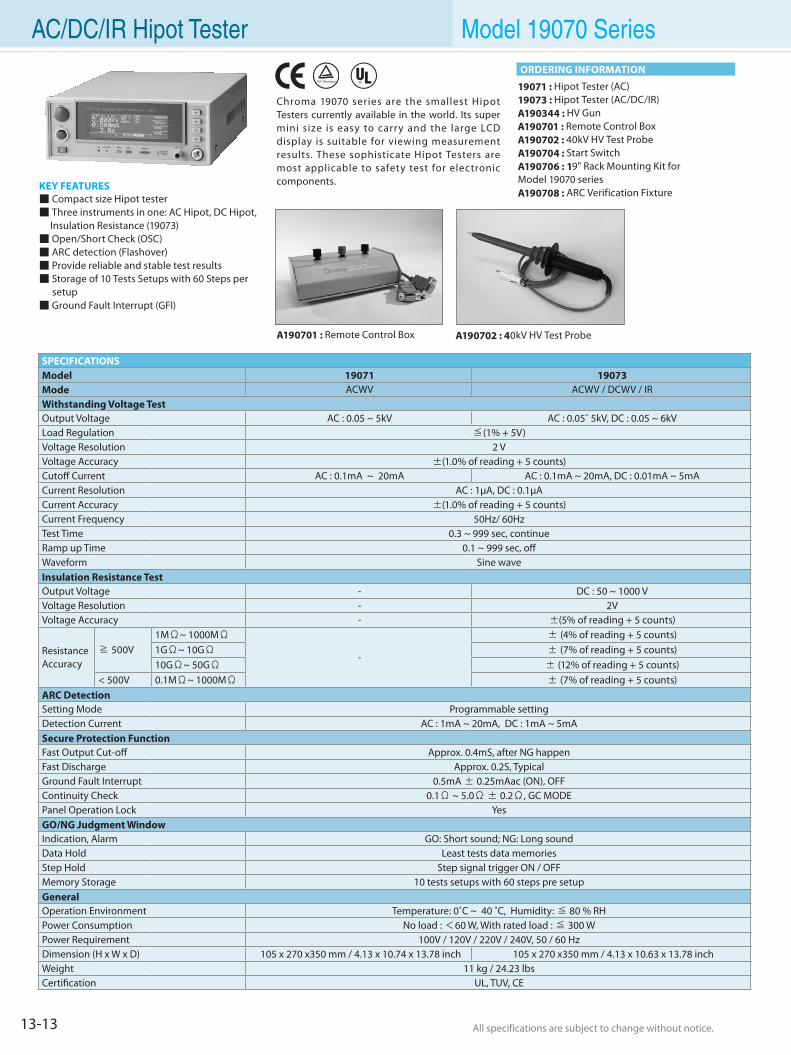
13-13 All specifications are subject to change without notice. All specifications are subject to change without notice.
AC/DC/IR Hipot Tester Model 19070 Series
KEY FEATURES Compact size Hipot tester Three instruments in one: AC Hipot, DC Hipot,
Insulation Resistance (19073) Open/Short Check (OSC) ARC detection (Flashover) Provide reliable and stable test results Storage of 10 Tests Setups with 60 Steps per
setup Ground Fault Interrupt (GFI)
19071 : Hipot Tester (AC)19073 : Hipot Tester (AC/DC/IR)A190344 : HV GunA190701 : Remote Control BoxA190702 : 40kV HV Test ProbeA190704 : Start SwitchA190706 : 19" Rack Mounting Kit forModel 19070 seriesA190708 : ARC Verification Fixture
Chroma 19070 series are the smallest Hipot Testers currently available in the world. Its super mini size is easy to carr y and the large LCD display is suitable for viewing measurement results. These sophisticate Hipot Testers are most applicable to safety test for electronic components.
A190701 : Remote Control Box A190702 : 40kV HV Test Probe
SPECIFICATIONSModel 19071 19073Mode ACWV ACWV / DCWV / IRWithstanding Voltage Test Output Voltage AC : 0.05 ~ 5kV AC : 0.05˜ 5kV, DC : 0.05 ~ 6kVLoad Regulation ≦(1% + 5V)Voltage Resolution 2 VVoltage Accuracy ±(1.0% of reading + 5 counts) Cutoff Current AC : 0.1mA ~ 20mA AC : 0.1mA ~ 20mA, DC : 0.01mA ~ 5mACurrent Resolution AC : 1µA, DC : 0.1µACurrent Accuracy ±(1.0% of reading + 5 counts) Current Frequency 50Hz/ 60HzTest Time 0.3 ~ 999 sec, continueRamp up Time 0.1 ~ 999 sec, offWaveform Sine waveInsulation Resistance TestOutput Voltage - DC : 50 ~ 1000 VVoltage Resolution - 2VVoltage Accuracy - ±(5% of reading + 5 counts)
Resistance Accuracy
≧ 500V1MΩ~ 1000MΩ
-
± (4% of reading + 5 counts)1GΩ~ 10GΩ ± (7% of reading + 5 counts)10GΩ~ 50GΩ ± (12% of reading + 5 counts)
< 500V 0.1MΩ~ 1000MΩ ± (7% of reading + 5 counts)ARC Detection Setting Mode Programmable setting Detection Current AC : 1mA ~ 20mA, DC : 1mA ~ 5mASecure Protection Function Fast Output Cut-off Approx. 0.4mS, after NG happenFast Discharge Approx. 0.2S, TypicalGround Fault Interrupt 0.5mA ± 0.25mAac (ON), OFFContinuity Check 0.1Ω ~ 5.0Ω ± 0.2Ω, GC MODEPanel Operation Lock YesGO/NG Judgment WindowIndication, Alarm GO: Short sound; NG: Long soundData Hold Least tests data memories Step Hold Step signal trigger ON / OFFMemory Storage 10 tests setups with 60 steps pre setupGeneralOperation Environment Temperature: 0˚C ~ 40 ˚C, Humidity: ≦ 80 % RH Power Consumption No load : <60 W, With rated load : ≦ 300 WPower Requirement 100V / 120V / 220V / 240V, 50 / 60 Hz Dimension (H x W x D) 105 x 270 x350 mm / 4.13 x 10.74 x 13.78 inch 105 x 270 x350 mm / 4.13 x 10.63 x 13.78 inchWeight 11 kg / 24.23 lbsCertification UL, TUV, CE
ORDERING INFORMATION
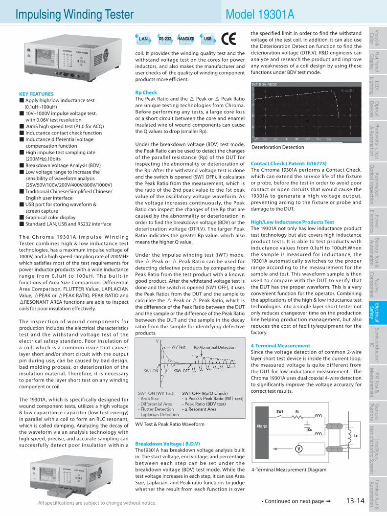
13-14All specifications are subject to change without notice. All specifications are subject to change without notice.
Flat PanelD
isplayPow
er Electronics
Electrical Safety
General
PurposePassive
Component
Semiconductor/
ICBattery Test & Autom
ationAutom
atedO
ptical Inspection Photovoltaic Test
& Automation
PXI Test &
Measurem
ent Video & Color
LED/
LightingO
ptical D
evicesIntelligent
Manufacturing System
Turnkey Test & Autom
ation
KEY FEATURES Apply high/low inductance test (0.1uH~100uH) 10V~1000V impulse voltage test, with 0.06V test resolution 20mS high speed test (P1.0 for ACQ) Inductance contact check function Inductance differential voltage compensation function High impulse test sampling rate (200MHz),10bits Breakdown Voltage Analysis (BDV) Low voltage range to increase the sensibility of waveform analysis (25V/50V/100V/200V/400V/800V/1000V) Traditional Chinese/Simplified Chinese/ English user interface USB port for storing waveform & screen capture Graphical color display Standard LAN, USB and RS232 interface
T h e C h r o m a 19 3 01A i m p u l s e W i n d i n g Tester combines high & low inductance test technologies, has a maximum impulse voltage of 1000V, and a high speed sampling rate of 200MHz which satisfies most of the test requirements for power inductor products with a wide inductance r a n g e f r o m 0.1u H t o 10 0u H. T h e b u i l t- i n functions of Area Size Comparison, Differential Area Comparison, FLUTTER Value, LAPLACIAN Value, ΔPEAK or ΔPEAK RATIO, PEAK RATIO and ΔRESONANT AREA functions are able to inspect coils for poor insulation effectively.
The insp ec tion of wound comp onent s for production includes the electrical characteristics test and the withstand voltage test of the electrical safety standard. Poor insulation of a coil, which is a common issue that causes layer short and/or short circuit with the output pin during use, can be caused by bad design, bad molding process, or deterioration of the insulation material. Therefore, it is necessary to perform the layer short test on any winding component or coil.
The 19301A, which is specifically designed for wound component tests, utilizes a high voltage & low capacitance capacitor (low test energy) in parallel with a coil to form an RLC resonant, which is called damping. Analyzing the decay of the waveform via an analysis technology with high speed, precise, and accurate sampling can successfully detect poor insulation within a
coil. It provides the winding quality test and the withstand voltage test on the cores for power inductors, and also makes the manufacturer and user checks of the quality of winding component products more efficient.
Rp CheckThe Peak Ratio and the Δ Peak or Δ Peak Ratio are unique testing technologies from Chroma. Before performing any tests, a large core loss or a short circuit between the core and enamel insulated wire of wound components can cause the Q values to drop (smaller Rp).
Under the breakdown voltage (BDV) test mode, the Peak Ratio can be used to detect the changes of the parallel resistance (Rp) of the DUT for inspecting the abnormality or deterioration of the Rp. After the withstand voltage test is done and the switch is opened (SW1 OFF), it calculates the Peak Ratio from the measurement, which is the ratio of the 2nd peak value to the 1st peak value of the oscillatory voltage waveform. As the voltage increases continuously, the Peak Ratio can inspect the changes of the Rp that are caused by the abnormality or deterioration in order to find the breakdown voltage (BDV) or the deterioration voltage (DTR.V). The larger Peak Ratio indicates the greater Rp value, which also means the higher Q value.
Under the impulse winding test (IWT) mode, the Δ Peak or Δ Peak Ratio can be used for detecting defective products by comparing the Peak Ratio from the test product with a known good product. After the withstand voltage test is done and the switch is opened (SW1 OFF), it uses the Peak Ratios from the DUT and the sample to calculate the Δ Peak or Δ Peak Ratio, which is the difference of the Peak Ratio between the DUT and the sample or the difference of the Peak Ratio between the DUT and the sample in the decay ratio from the sample for identifying defective products.
Breakdown Voltage ( B.D.V)The19301A has breakdown voltage analysis built in. The start voltage, end voltage, and percentage b e t we e n e a c h s te p c a n b e s e t u n d e r t h e breakdown voltage (BDV) test mode. While the test voltage increases in each step, it can use Area Size, Laplacian, and Peak ratio functions to judge whether the result from each function is over
the specified limit in order to find the withstand voltage of the test coil. In addition, it can also use the Deterioration Detection function to find the deterioration voltage (DTR.V). R&D engineers can analyze and research the product and improve any weaknesses of a coil design by using these functions under BDV test mode.
Contact Check ( Patent: I516773)The Chroma 19301A performs a Contact Check, which can extend the service life of the fixture or probe, before the test in order to avoid poor contact or open circuits that would cause the 19301A to generate a high voltage output, preventing arcing to the fixture or probe and damage to the DUT.
High/Low Inductance Products TestThe 19301A not only has low inductance product test technology but also covers high inductance product tests. It is able to test products with inductance values from 0.1uH to 100uH.When the sample is measured for inductance, the 19301A automatically switches to the proper range according to the measurement for the sample and test. This waveform sample is then used to compare with the DUT to verify that the DUT has the proper waveform. This is a very convenient function for the operator. Combining the applications of the high & low inductance test technologies into a single layer short tester not only reduces changeover time on the production line helping production management, but also reduces the cost of facility/equipment for the factory.
4-Terminal MeasurementSince the voltage detection of common 2-wire layer short test device is inside the current loop, the measured voltage is quite dif ferent from the DUT for low inductance measurement. The Chroma 19301A uses dual coaxial 4-wire detection to significantly improve the voltage accuracy for correct test results.
• Continued on next page
Impulsing Winding Tester Model 19301A
WV Test & Peak Ratio Waveform
4-Terminal Measurement Diagram
Deterioration Detection
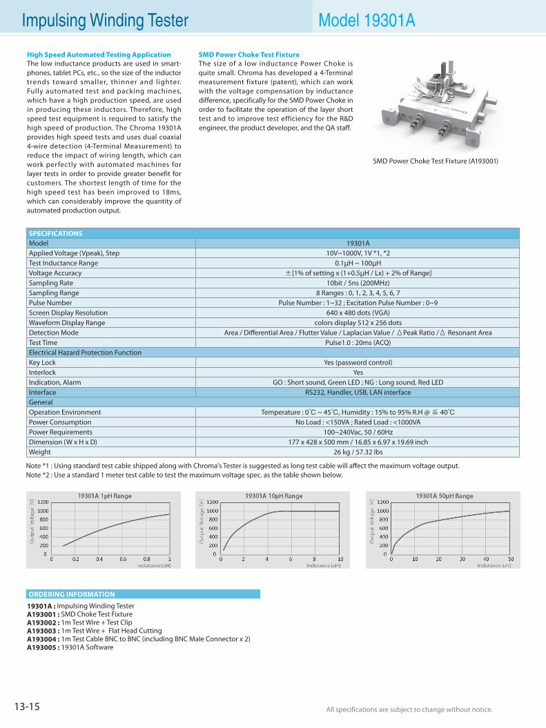
13-15 All specifications are subject to change without notice. All specifications are subject to change without notice.
Impulsing Winding Tester Model 19301A
19301A : Impulsing Winding TesterA193001 : SMD Choke Test Fixture A193002 : 1m Test Wire + Test ClipA193003 : 1m Test Wire + Flat Head CuttingA193004 : 1m Test Cable BNC to BNC (including BNC Male Connector x 2)A193005 : 19301A Software
High Speed Automated Testing ApplicationThe low inductance products are used in smart-phones, tablet PCs, etc., so the size of the inductor trends toward smaller, thinner and l ighter. Fully automated test and packing machines, which have a high production speed, are used in producing these inductors. Therefore, high speed test equipment is required to satisfy the high speed of production. The Chroma 19301A provides high speed tests and uses dual coaxial 4-wire detection (4-Terminal Measurement) to reduce the impact of wiring length, which can work perfectly with automated machines for layer tests in order to provide greater benefit for customers. The shortest length of time for the high speed test has been improved to 18ms, which can considerably improve the quantity of automated production output.
SMD Power Choke Test FixtureThe size of a low inductance Power Choke is quite small. Chroma has developed a 4-Terminal measurement fixture (patent), which can work with the voltage compensation by inductance difference, specifically for the SMD Power Choke in order to facilitate the operation of the layer short test and to improve test efficiency for the R&D engineer, the product developer, and the QA staff.
ORDERING INFORMATION
Note *1 : Using standard test cable shipped along with Chroma's Tester is suggested as long test cable will affect the maximum voltage output.Note *2 : Use a standard 1 meter test cable to test the maximum voltage spec. as the table shown below.
SPECIFICATIONSModel 19301AApplied Voltage (Vpeak), Step 10V~1000V, 1V *1, *2Test Inductance Range 0.1µH ~ 100µHVoltage Accuracy ±[1% of setting x (1+0.5µH / Lx) + 2% of Range]Sampling Rate 10bit / 5ns (200MHz)Sampling Range 8 Ranges : 0, 1, 2, 3, 4, 5, 6, 7Pulse Number Pulse Number : 1~32 ; Excitation Pulse Number : 0~9Screen Display Resolution 640 x 480 dots (VGA)Waveform Display Range colors display 512 x 256 dotsDetection Mode Area / Differential Area / Flutter Value / Laplacian Value / ΔPeak Ratio /Δ Resonant Area Test Time Pulse1.0 : 20ms (ACQ)Electrical Hazard Protection Function Key Lock Yes (password control)Interlock YesIndication, Alarm GO : Short sound, Green LED ; NG : Long sound, Red LEDInterface RS232, Handler, USB, LAN interfaceGeneralOperation Environment Temperature : 0 ~ 45, Humidity : 15% to 95% R.H @ ≦ 40Power Consumption No Load : <150VA ; Rated Load : <1000VAPower Requirements 100~240Vac, 50 / 60HzDimension (W x H x D) 177 x 428 x 500 mm / 16.85 x 6.97 x 19.69 inch Weight 26 kg / 57.32 lbs
SMD Power Choke Test Fixture (A193001)
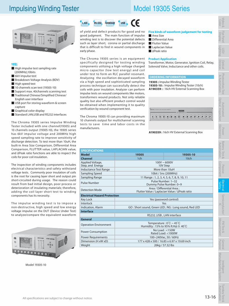
13-16All specifications are subject to change without notice. All specifications are subject to change without notice.
Flat PanelD
isplayPow
er Electronics
Electrical Safety
General
PurposePassive
Component
Semiconductor/
ICBattery Test & Autom
ationAutom
atedO
ptical Inspection Photovoltaic Test
& Automation
PXI Test &
Measurem
ent Video & Color
LED/
LightingO
ptical D
evicesIntelligent
Manufacturing System
Turnkey Test & Autom
ation
19305 : Impulse Winding Tester19305-10 : Impulse Winding Tester (10ch)A190359 : : 16ch HV External Scanning Box
ORDERING INFORMATION
特點 High impulse test sampling rate
(200MHz),10bits 6kV impulse test Breakdown Voltage Analysis (BDV) High speed test 10 channels scan test (19305-10) Support max. 40channels scanning test Traditional Chinese/Simplified Chinese/ English user interface USB port for storing waveform & screen
capture Graphical color display Standard LAN,USB and RS232 interfaces
The Chroma 19305 series Impulse Winding Tester included with one channel(19305) and 10 channels output (19305-10), the 19305 series has 6kV impulse voltage and 200MHz high speed sampling rate to improve sensitivity of discharge detection. To test more than 10uH, the built-in Area Size Comparison, Differential Area Comparison, FLUTTER value, LAPLACIAN value, and ∆Peak ratio functions are able to inspect the coils for poor coil insulation.
The inspection of winding components includes electrical characteristics and safety withstand voltage tests. Commonly poor insulation of coils is the root for causing layer short and output pin short-circuited during usage. The reason could result from bad initial design, poor process or deterioration of insulating materials; therefore, adding the coil layer shor t test to winding components has its necessity.
T h e i m p u l s e w i n d i n g t e s t i s t o i m p o s e a non-destructive, high speed and low energy voltage impulse on the DUT (Device Under Test) to analyze/compare the equivalent waveform
of yield and defect products for good and no good judgment. The main function of impulse winding test is to discover the potential defects such as layer short, corona or partial discharge that is difficult to find in wound components in early phase.
The Chroma 19305 ser ies is an equipment sp e ci f ic a l ly designe d for tes t ing winding components utilizing a high voltage charged micro capacitor (low test energy) and coi l under test to form an RLC parallel resonant. Analyzing the oscillation decayed waveform via a high speed and sophisticated sampling process technique can successfully detect the coils with poor insulation. Analyzer can perform impulse tests on wound components like motors, transformers wound products. Not only reliable quality but also efficient product control would be obtained when implementing it to quality verification by wound component test.
The Chroma 19305-10 can providing maximum 10 channels output for multichannel scanning tes t s to s ave t im e and lab or cos t s in the manufacturers.
Five kinds of waveform judgement for testing Area Size Differential Area Flutter Value Laplacian Value ∆Peak ratio
Product ApplicationTransformer, Motor, Generator, Ignition Coil, Relay, Solenoid Valve, Inductance and other coils.
Model 19305-10
SPECIFICATIONSModel 19305 19305-10 Channel 1ch 10chApplied Voltage,Step, and Energy
100V ~ 6000V10V Step
Inductance Test Range More than 10uH Sampling Speed 10bit / 5ns (200MHz)Sampling Range 11 Range : 1, 2, 3, 4, 5, 6, 7, 8, 9, 10, 11
Pulse Number Pulse Number: 1~32Dummy Pulse Number: 0~9
Detection Mode Area / Differential Area ;Flutter Value / Laplacian Value / ∆Peak ratio
Electrical Hazard ProtectionKey Lock Yes (password control)Interlock YesIndication, Alarm GO : Short sound, Green LED ; NG : Long sound, Red LEDInterface
RS232 ,USB , LAN interfaceGeneral
Operation Environment Temperature : 0 ~ 45Humidity : 15% to 95% R.H@≦ 40
Power Consumption No Load : <150WRated Load: <1000W
Power Requirements 100~240Vac, 50 / 60HzDimension (H xW xD) 177 x 428 x 500 / 16.85 x 6.97 x 19.69 inch Weight 26kg / 57.32 lbs
A190359 : 16ch HV External Scanning Box
Impulsing Winding Tester Model 19305 Series
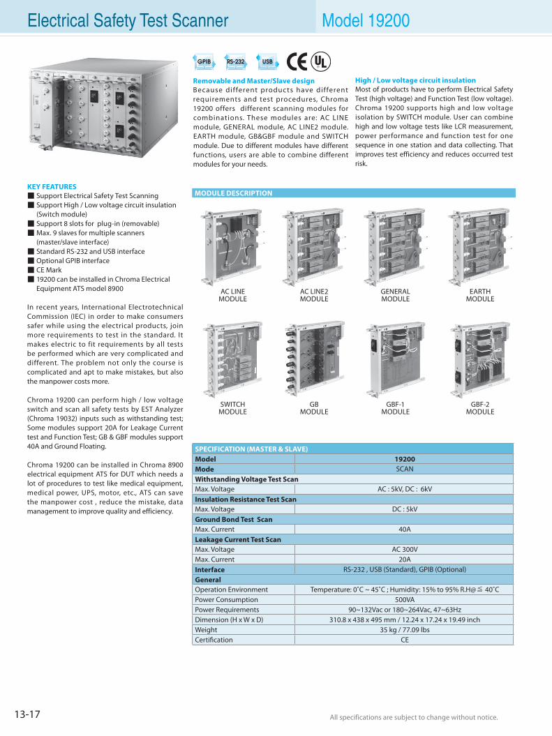
13-17 All specifications are subject to change without notice. All specifications are subject to change without notice.
Electrical Safety Test Scanner Model 19200
SPECIFICATION (MASTER & SLAVE)Model 19200Mode SCANWithstanding Voltage Test ScanMax. Voltage AC : 5kV, DC : 6kVInsulation Resistance Test ScanMax. Voltage DC : 5kVGround Bond Test ScanMax. Current 40ALeakage Current Test ScanMax. Voltage AC 300VMax. Current 20AInterface RS-232 , USB (Standard), GPIB (Optional)GeneralOperation Environment Temperature: 0˚C ~ 45˚C ; Humidity: 15% to 95% R.H@≦ 40˚CPower Consumption 500VAPower Requirements 90~132Vac or 180~264Vac, 47~63HzDimension (H x W x D) 310.8 x 438 x 495 mm / 12.24 x 17.24 x 19.49 inchWeight 35 kg / 77.09 lbsCertification CE
KEY FEATURES Support Electrical Safety Test Scanning Support High / Low voltage circuit insulation (Switch module) Support 8 slots for plug-in (removable) Max. 9 slaves for multiple scanners (master/slave interface) Standard RS-232 and USB interface Optional GPIB interface CE Mark 19200 can be installed in Chroma Electrical Equipment ATS model 8900
In recent years, International Electrotechnical Commission (IEC) in order to make consumers safer while using the electrical products, join more requirements to test in the standard. It makes electric to fit requirements by all tests be performed which are very complicated and different. The problem not only the course is complicated and apt to make mistakes, but also the manpower costs more.
Chroma 19200 can perform high / low voltage switch and scan all safety tests by EST Analyzer (Chroma 19032) inputs such as withstanding test; Some modules support 20A for Leakage Current test and Function Test; GB & GBF modules support 40A and Ground Floating.
Chroma 19200 can be installed in Chroma 8900 electrical equipment ATS for DUT which needs a lot of procedures to test like medical equipment, medical power, UPS, motor, etc., ATS can save the manpower cost , reduce the mistake, data management to improve quality and efficiency.
Removable and Master/Slave designBecause different products have different requirements and test procedures, Chroma 19200 offers different scanning modules for combinations. These modules are: AC LINE module, GENERAL module, AC LINE2 module. EARTH module, GB&GBF module and SWITCH module. Due to different modules have different functions, users are able to combine different modules for your needs.
AC LINEMODULE
AC LINE2MODULE
GENERALMODULE
EARTHMODULE
GBF-1MODULE
SWITCHMODULE
High / Low voltage circuit insulationMost of products have to perform Electrical Safety Test (high voltage) and Function Test (low voltage). Chroma 19200 supports high and low voltage isolation by SWITCH module. User can combine high and low voltage tests like LCR measurement, power performance and function test for one sequence in one station and data collecting. That improves test efficiency and reduces occurred test risk.
GBMODULE
GBF-2MODULE
MODULE DESCRIPTION
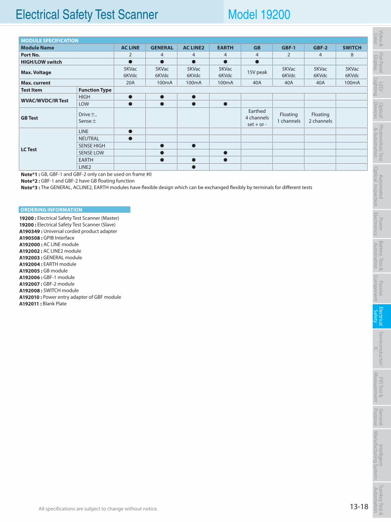
13-18All specifications are subject to change without notice. All specifications are subject to change without notice.
Flat PanelD
isplayPow
er Electronics
Electrical Safety
General
PurposePassive
Component
Semiconductor/
ICBattery Test & Autom
ationAutom
atedO
ptical Inspection Photovoltaic Test
& Automation
PXI Test &
Measurem
ent Video & Color
LED/
LightingO
ptical D
evicesIntelligent
Manufacturing System
Turnkey Test & Autom
ation Electrical Safety Test Scanner Model 19200
19200 : Electrical Safety Test Scanner (Master)19200 : Electrical Safety Test Scanner (Slave)A190349 : Universal corded product adapterA190508 : GPIB InterfaceA192000 : AC LINE moduleA192002 : AC LINE2 moduleA192003 : GENERAL moduleA192004 : EARTH moduleA192005 : GB moduleA192006 : GBF-1 moduleA192007 : GBF-2 moduleA192008 : SWITCH moduleA192010 : Power entry adapter of GBF moduleA192011 : Blank Plate
MODULE SPECIFICATIONModule Name AC LINE GENERAL AC LINE2 EARTH GB GBF-1 GBF-2 SWITCHPort No. 2 4 4 4 4 2 4 8HIGH/LOW switch
Max. Voltage5KVac6KVdc
5KVac6KVdc
5KVac6KVdc
5KVac6KVdc
15V peak5KVac6KVdc
5KVac6KVdc
5KVac6KVdc
Max. current 20A 100mA 100mA 100mA 40A 40A 40A 100mATest Item Function Type
WVAC/WVDC/IR TestHIGH
LOW
GB TestDrive±,Sense±
Earthed4 channelsset + or -
Floating1 channels
Floating2 channels
LC Test
LINE
NEUTRAL
SENSE HIGH
SENSE LOW
EARTH
LINE2
Note*1 : GB, GBF-1 and GBF-2 only can be used on frame #0Note*2 : GBF-1 and GBF-2 have GB floating functionNote*3 : The GENERAL, ACLINE2, EARTH modules have flexible design which can be exchanged flexibly by terminals for different tests
ORDERING INFORMATION
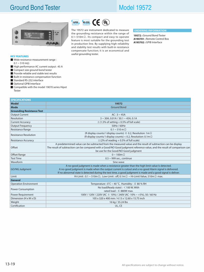
13-19 All specifications are subject to change without notice. All specifications are subject to change without notice.
Ground Bond Tester Model 19572
KEY FEATURES Wide resistance measurement range : 0.1 ~ 510 mΩ High performance AC current output : 45 A Compact size ground bond tester Provide reliable and stable test results Built-in resistance compensation function Standard RS-232 interface Optional GPIB Interface Compatible with the model 19070 series Hipot Tester
19572 : Ground Bond TesterA190701 : Remote Control BoxA195702 : GPIB Interface
The 19572 are instrument dedicated to measure the grounding resistance within the range of 0.1~510mΩ. Its compact and easy to operate feature is most suitable for the grounding test in production line. By supplying high reliability and stability test results with built-in resistance compensate function; it is an economical and useful grounding tester.
SPECIFICATIONSModel 19572Mode Ground BondGrounding Resistance TestOutput Current AC : 3 ~ 45AResolution 3 ~ 30A, 0.01A / 30.1 ~ 45A, 0.1ACurrent Accuracy ±(1.5% of setting + 0.5% of full scale)Output Frequency 50Hz / 60HzResistance Range 0.1 ~ 510 mΩ
Resistance Resolution(R display counts/ I display counts) ≧ 0.2, Resolution: 1mΩ(R display counts/ I display counts) < 0.2, Resolution: 0.1mΩ
Resistance Accuracy ±(2% of reading + 0.5% of full scale)
OffsetA predetermined value can be subtracted from the measured value and the result of subtraction can be display
The result of subtraction can be compared with a Good/NO Good judgment reference value, and the result of comparison can be use for the Good/NO Good judgment
Offset Range 0 ~ 100mΩTest Time 0.5 ~ 999 sec., continueWaveform Sine wave
GO/NG JudgmentA no-good judgment is made when a resistance greater than the high limit value Is detected.
A no-good judgment is made when the output current is cutout and a no-good Alarm signal is delivered. If no abnormal state is detected during the test time, a good judgment is made and a good signal is deliver.
Limit Hi-Limit : 0.1 ~ 510mΩ; Low-Limit : off, 0.1mΩ ~ Hi-Limit Value, 510mΩ max.GeneralOperation Environment Temperature : 0˚C ~ 40 ˚C, Humidity : ≦ 80 % RH
Power ConsumptionNo load(Ready state) : <100 W, With
rated load : ≦ 880W max.Power Requirement 100V / 120V / 220V (AC ± 10%) / 240V (AC -10% ~ +5%), 50 / 60 HzDimension (H x W x D) 105 x 320 x 400 mm / 4.13 x 12.60 x 15.75 inchWeight 16 kg / 35.24 lbsCertification UL, CE
ORDERING INFORMATION
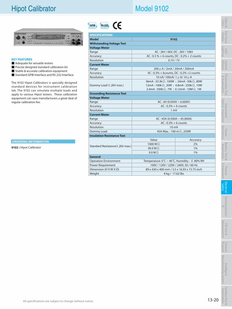
13-20All specifications are subject to change without notice. All specifications are subject to change without notice.
Flat PanelD
isplayPow
er Electronics
Electrical Safety
General
PurposePassive
Component
Semiconductor/
ICBattery Test & Autom
ationAutom
atedO
ptical Inspection Photovoltaic Test
& Automation
PXI Test &
Measurem
ent Video & Color
LED/
LightingO
ptical D
evicesIntelligent
Manufacturing System
Turnkey Test & Autom
ation Hipot Calibrator Model 9102
KEY FEATURES Adequate for versatile testers Precise designed standard calibration kit Stable & accurate calibration equipment Standard GPIB Interface and RS-232 Interface
The 9102 Hipot Calibrators is specially designed standard devices for instrument calibration lab. The 9102 can simulate multiple loads and apply to various Hipot testers. These calibration equipment can save manufacturers a great deal of regular calibration fee.
9102 : Hipot Calibrator
SPECIFICATIONSModel 9102 Withstanding Voltage TestVoltage Meter Range AC : 2kV / 6kV, DC : 2kV / 10kVAccuracy AC : 0.3 % + 6 counts, DC : 0.2% + 2 countsResolution 0.1V / 1VCurrent Meter Range 200μA / 2mA / 20mA / 200mAAccuracy AC : 0.3% + 6counts, DC : 0.2% +2 countsResolution 10 nA/ 100nA/ 1μA/ 10μA
Dummy Load (1.2kV max.)36mA : 33.3kΩ, 100W ; 24mA : 50kΩ, 80W 12mA : 100kΩ, 30W ; 4.8mA : 250kΩ, 10W 2.4mA : 500kΩ, 7W ; 0.12mA : 10MΩ, 1W
Grounding Resistance TestVoltage Meter Range AC : 6V (0.050V ~ 6.000V)Accuracy AC : 0.3% + 6 countsResolution 1 mVCurrent Meter Range AC : 45A (0.500A ~ 45.000A)Accuracy AC : 0.3% + 6 countsResolution 10 mADummy Load 45A Max. : 100 mΩ, 250W Insulation Resistance Test
Standard Resistance(1.2kV max.)
Value Accuracy 1000 MΩ 2% 90.9 MΩ 1% 9.9 MΩ 1%
General Operation Environment Temperature: 0˚C ~ 40˚C, Humidity : ≦ 80% RHPower Requirement 100V / 120V / 220V / 240V, 50 / 60 Hz Dimension (H X W X D) 89 x 430 x 400 mm / 3.5 x 16.93 x 15.75 inchWeight 8 kg / 17.62 lbs
ORDERING INFORMATION
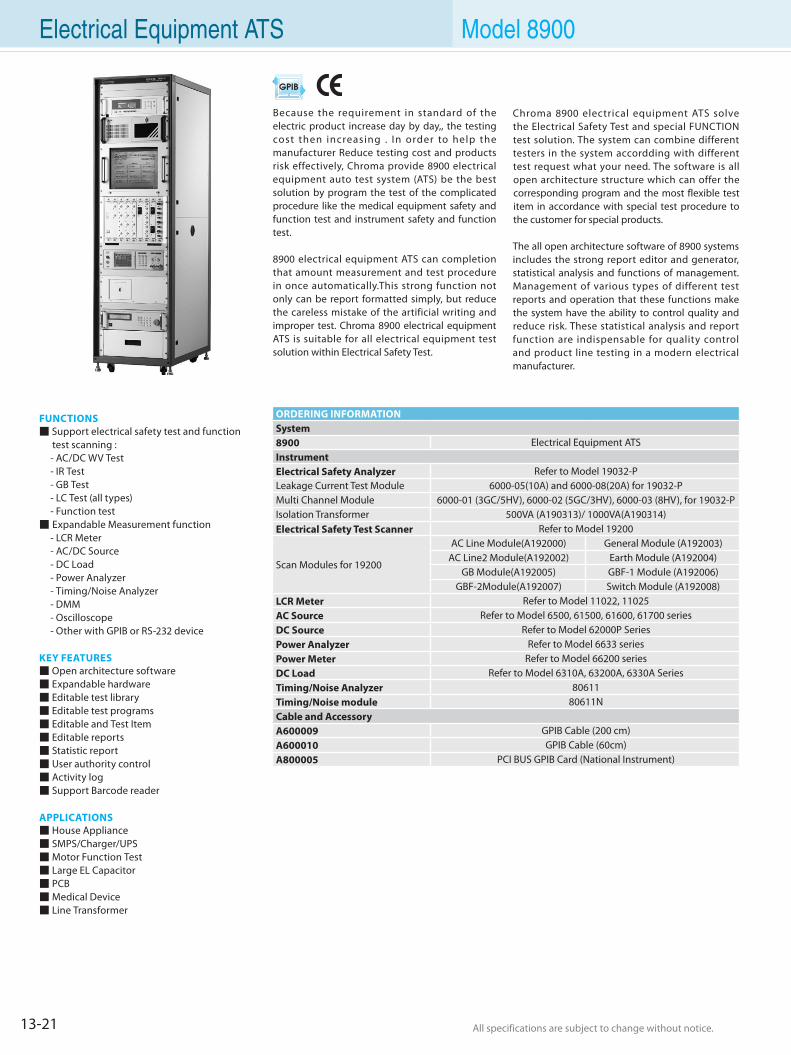
13-21 All specifications are subject to change without notice. All specifications are subject to change without notice.
Electrical Equipment ATS Model 8900
FUNCTIONS Support electrical safety test and function
test scanning : - AC/DC WV Test - IR Test - GB Test - LC Test (all types) - Function test Expandable Measurement function - LCR Meter - AC/DC Source - DC Load - Power Analyzer - Timing/Noise Analyzer - DMM - Oscilloscope - Other with GPIB or RS-232 device
KEY FEATURES Open architecture software Expandable hardware Editable test library Editable test programs Editable and Test Item Editable reports Statistic report User authority control Activity log Support Barcode reader
APPLICATIONS House Appliance SMPS/Charger/UPS Motor Function Test Large EL Capacitor PCB Medical Device Line Transformer
Because the requirement in standard of the electric product increase day by day,, the testing cost then increasing . In order to help the manufacturer Reduce testing cost and products risk effectively, Chroma provide 8900 electrical equipment auto test system (ATS) be the best solution by program the test of the complicated procedure like the medical equipment safety and function test and instrument safety and function test.
8900 electrical equipment ATS can completion that amount measurement and test procedure in once automatically.This strong function not only can be report formatted simply, but reduce the careless mistake of the artificial writing and improper test. Chroma 8900 electrical equipment ATS is suitable for all electrical equipment test solution within Electrical Safety Test.
ORDERING INFORMATIONSystem8900 Electrical Equipment ATSInstrumentElectrical Safety Analyzer Refer to Model 19032-PLeakage Current Test Module 6000-05(10A) and 6000-08(20A) for 19032-PMulti Channel Module 6000-01 (3GC/5HV), 6000-02 (5GC/3HV), 6000-03 (8HV), for 19032-PIsolation Transformer 500VA (A190313)/ 1000VA(A190314)Electrical Safety Test Scanner Refer to Model 19200
Scan Modules for 19200
AC Line Module(A192000) General Module (A192003)AC Line2 Module(A192002) Earth Module (A192004)
GB Module(A192005) GBF-1 Module (A192006)GBF-2Module(A192007) Switch Module (A192008)
LCR Meter Refer to Model 11022, 11025AC Source Refer to Model 6500, 61500, 61600, 61700 seriesDC Source Refer to Model 62000P SeriesPower Analyzer Refer to Model 6633 seriesPower Meter Refer to Model 66200 seriesDC Load Refer to Model 6310A, 63200A, 6330A SeriesTiming/Noise Analyzer 80611Timing/Noise module 80611NCable and AccessoryA600009 GPIB Cable (200 cm)A600010 GPIB Cable (60cm)A800005 PCI BUS GPIB Card (National Instrument)
Chroma 8900 electrical equipment ATS solve the Electrical Safety Test and special FUNCTION test solution. The system can combine different testers in the system accordding with different test request what your need. The software is all open architecture structure which can offer the corresponding program and the most flexible test item in accordance with special test procedure to the customer for special products.
The all open architecture software of 8900 systems includes the strong report editor and generator, statistical analysis and functions of management. Management of various types of different test reports and operation that these functions make the system have the ability to control quality and reduce risk. These statistical analysis and report function are indispensable for quality control and product line testing in a modern electrical manufacturer.
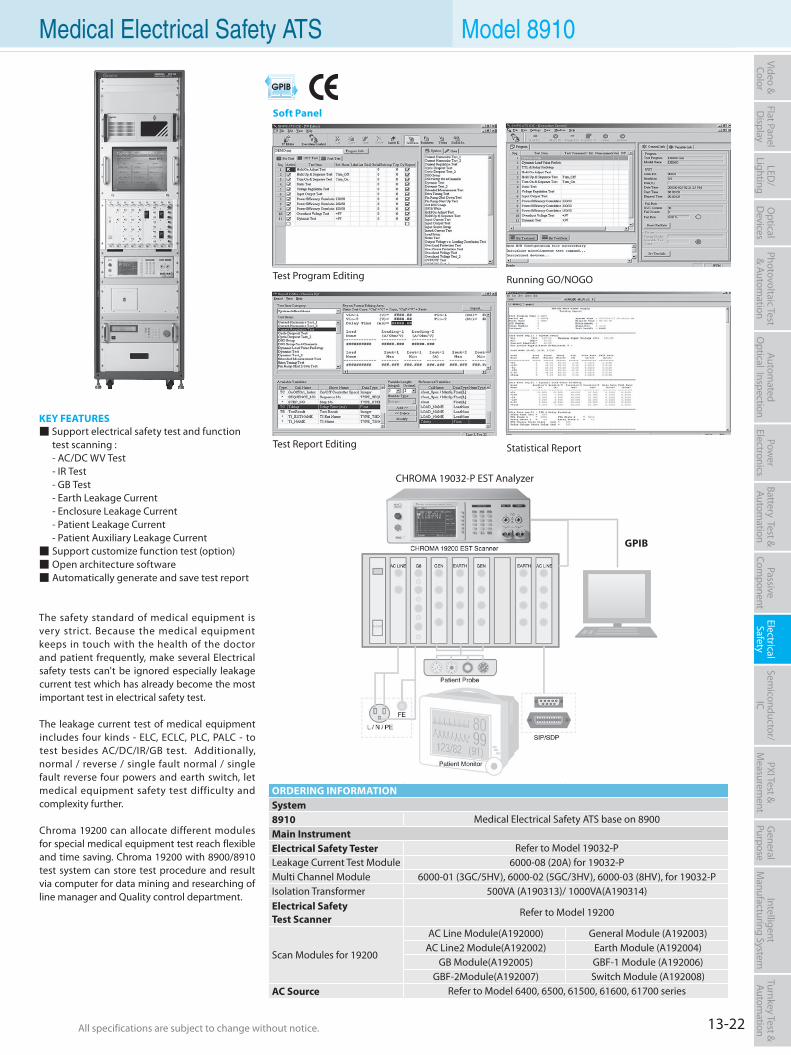
13-22All specifications are subject to change without notice. All specifications are subject to change without notice.
Flat PanelD
isplayPow
er Electronics
Electrical Safety
General
PurposePassive
Component
Semiconductor/
ICBattery Test & Autom
ationAutom
atedO
ptical Inspection Photovoltaic Test
& Automation
PXI Test &
Measurem
ent Video & Color
LED/
LightingO
ptical D
evicesIntelligent
Manufacturing System
Turnkey Test & Autom
ation Medical Electrical Safety ATS Model 8910
KEY FEATURES Support electrical safety test and function test scanning : - AC/DC WV Test - IR Test - GB Test - Earth Leakage Current - Enclosure Leakage Current - Patient Leakage Current - Patient Auxiliary Leakage Current Support customize function test (option) Open architecture software Automatically generate and save test report
The safety standard of medical equipment is very strict. Because the medical equipment keeps in touch with the health of the doctor and patient frequently, make several Electrical safety tests can't be ignored especially leakage current test which has already become the most important test in electrical safety test.
The leakage current test of medical equipment includes four kinds - ELC, ECLC, PLC, PALC - to test besides AC/DC/IR/GB test. Additionally, normal / reverse / single fault normal / single fault reverse four powers and earth switch, let medical equipment safety test difficulty and complexity further.
Chroma 19200 can allocate different modules for special medical equipment test reach flexible and time saving. Chroma 19200 with 8900/8910 test system can store test procedure and result via computer for data mining and researching of line manager and Quality control department.
ORDERING INFORMATIONSystem8910 Medical Electrical Safety ATS base on 8900Main InstrumentElectrical Safety Tester Refer to Model 19032-PLeakage Current Test Module 6000-08 (20A) for 19032-PMulti Channel Module 6000-01 (3GC/5HV), 6000-02 (5GC/3HV), 6000-03 (8HV), for 19032-PIsolation Transformer 500VA (A190313)/ 1000VA(A190314)Electrical SafetyTest Scanner
Refer to Model 19200
Scan Modules for 19200
AC Line Module(A192000) General Module (A192003)AC Line2 Module(A192002) Earth Module (A192004)
GB Module(A192005) GBF-1 Module (A192006)GBF-2Module(A192007) Switch Module (A192008)
AC Source Refer to Model 6400, 6500, 61500, 61600, 61700 series
GPIB
CHROMA 19032-P EST Analyzer
Test Program Editing
Test Report Editing
Running GO/NOGO
Statistical Report
Soft Panel
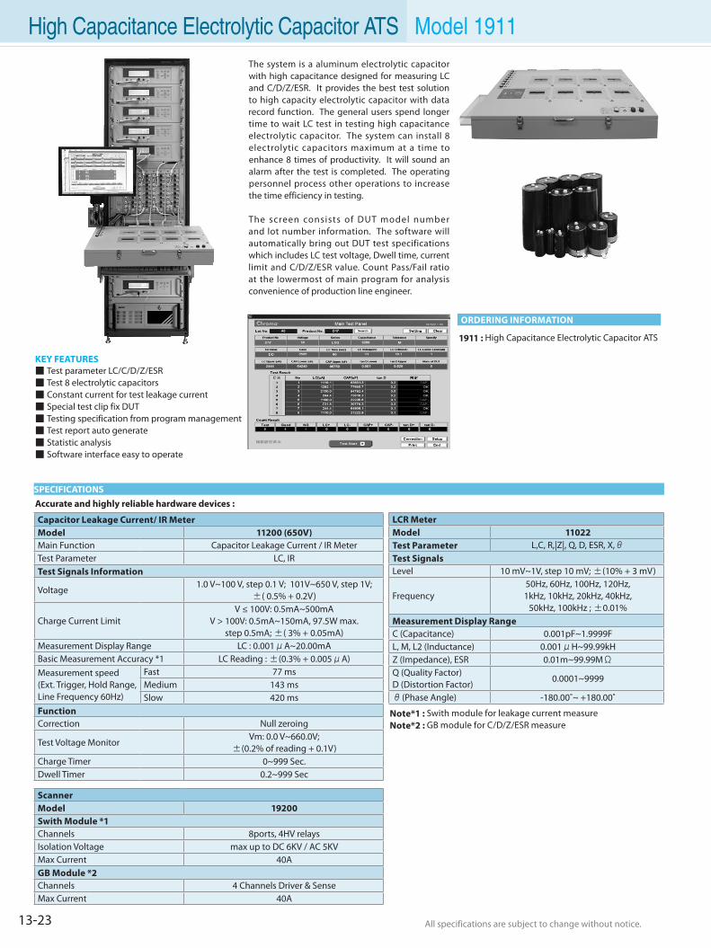
13-23 All specifications are subject to change without notice. All specifications are subject to change without notice.
KEY FEATURES Test parameter LC/C/D/Z/ESR Test 8 electrolytic capacitors Constant current for test leakage current Special test clip fix DUT Testing specification from program management Test report auto generate Statistic analysis Software interface easy to operate
The system is a aluminum electrolytic capacitor with high capacitance designed for measuring LC and C/D/Z/ESR. It provides the best test solution to high capacity electrolytic capacitor with data record function. The general users spend longer time to wait LC test in testing high capacitance electrolytic capacitor. The system can install 8 electrolytic capacitors maximum at a time to enhance 8 times of productivity. It will sound an alarm after the test is completed. The operating personnel process other operations to increase the time efficiency in testing.
The screen consists of DUT model number and lot number information. The software will automatically bring out DUT test specifications which includes LC test voltage, Dwell time, current limit and C/D/Z/ESR value. Count Pass/Fail ratio at the lowermost of main program for analysis convenience of production line engineer.
SPECIFICATIONSAccurate and highly reliable hardware devices :
LCR MeterModel 11022Test Parameter L,C, R,|Z|, Q, D, ESR, X,θTest SignalsLevel 10 mV~1V, step 10 mV; ±(10% + 3 mV)
Frequency50Hz, 60Hz, 100Hz, 120Hz, 1kHz, 10kHz, 20kHz, 40kHz,
50kHz, 100kHz ; ±0.01%Measurement Display RangeC (Capacitance) 0.001pF~1.9999FL, M, L2 (Inductance) 0.001μH~99.99kHZ (Impedance), ESR 0.01m~99.99MΩQ (Quality Factor)D (Distortion Factor)
0.0001~9999
θ(Phase Angle) -180.00˚~ +180.00˚
Capacitor Leakage Current/ IR MeterModel 11200 (650V)Main Function Capacitor Leakage Current / IR MeterTest Parameter LC, IRTest Signals Information
Voltage1.0 V~100 V, step 0.1 V; 101V~650 V, step 1V;
±( 0.5% + 0.2V)
Charge Current LimitV ≤ 100V: 0.5mA~500mA
V > 100V: 0.5mA~150mA, 97.5W max.step 0.5mA; ±( 3% + 0.05mA)
Measurement Display Range LC : 0.001μA~20.00mABasic Measurement Accuracy *1 LC Reading : ±(0.3% + 0.005μA)Measurement speed(Ext. Trigger, Hold Range, Line Frequency 60Hz)
Fast 77 msMedium 143 msSlow 420 ms
FunctionCorrection Null zeroing
Test Voltage MonitorVm: 0.0 V~660.0V;
±(0.2% of reading + 0.1V)Charge Timer 0~999 Sec.Dwell Timer 0.2~999 Sec
Scanner Model 19200Swith Module *1Channels 8ports, 4HV relaysIsolation Voltage max up to DC 6KV / AC 5KVMax Current 40AGB Module *2Channels 4 Channels Driver & SenseMax Current 40A
Note*1 : Swith module for leakage current measureNote*2 : GB module for C/D/Z/ESR measure
1911 : High Capacitance Electrolytic Capacitor ATS
ORDERING INFORMATION
High Capacitance Electrolytic Capacitor ATS Model 1911
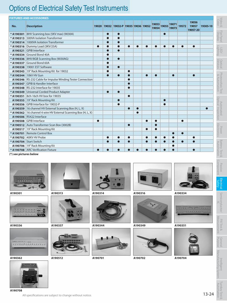
13-24All specifications are subject to change without notice. All specifications are subject to change without notice.
Flat PanelD
isplayPow
er Electronics
Electrical Safety
General
PurposePassive
Component
Semiconductor/
ICBattery Test & Autom
ationAutom
atedO
ptical Inspection Photovoltaic Test
& Automation
PXI Test &
Measurem
ent Video & Color
LED/
LightingO
ptical D
evicesIntelligent
Manufacturing System
Turnkey Test & Autom
ation Options of Electrical Safety Test InstrumentsFIXTURES AND ACCESSORIES
No. Description 19020 19032 19032-P 19035 19036 190521905319054
190551907119073
195721905619057
19057-2019305-10
* A190301 8HV Scanning box (5KV max) (9030A)
* A190313 500VA Isolation Transformer
* A190314 1000VA Isolation Transformer
* A190316 Dummy Load (3KV/25A)
A190321 GPIB Interface
* A190334 Ground Bond 40A
* A190336 8HV/8GB Scanning Box (9030AG)
* A190337 Ground Bond 60A
A190338 19001 EST Software
A190343 19" Rack Mounting Kit for 19032
* A190344 10kV HV Gun
A190346 RS-232 Cable for Impulse Winding Tester Connection
A190347 GPIB & Handler Interface
A190348 RS-232 Interface for 19035
* A190349 Universal Corded Product Adapter
* A190351 8ch-16ch HV box for 19035
A190355 19" Rack Mounting Kit
A190356 GPIB Interface for 19032-P
A190359 16 channel HV External Scanning Box (H, L, X)
* A190362 16 channel 4 wire HV External Scanning Box (H, L, X)
A190506 RS422 InterfaceA190508 GPIB Interface
* A190512 Auto Transformer Scan Box (3002B)
A190517 19" Rack Mounting Kit
* A190701 Remote Control Box
* A190702 40KV HV Probe
* A190704 Start Switch
A190706 19" Rack Mounting Kit
* A190708 ARC Verification Fixture
(*) see pictures below
A190313 A190314A190301
A190702A190512A190362 A190704A190701
A190316
A190337A190336 A190344
A190708
A190334
A190351A190349Note*1 : Swith module for leakage current measureNote*2 : GB module for C/D/Z/ESR measure
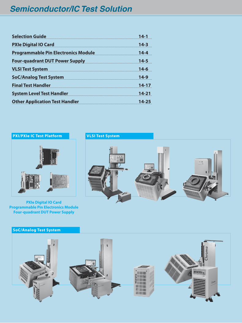
Semiconductor/IC Test Solution
PXIe Digital IO CardProgrammable Pin Electronics Module
Four-quadrant DUT Power Supply
VLSI Test SystemPXI/PXIe IC Test Platform
SoC/Analog Test System
Selection Guide 14-1
PXIe Digital IO Card 14-3
Programmable Pin Electronics Module 14-4
Four-quadrant DUT Power Supply 14-5
VLSI Test System 14-6
SoC/Analog Test System 14-9
Final Test Handler 14-17
System Level Test Handler 14-21
Other Application Test Handler 14-25
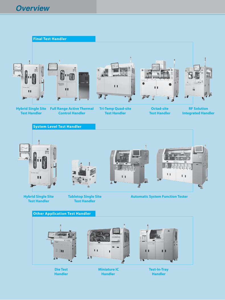
Overview
Final Test Handler
System Level Test Handler
Other Application Test Handler
Automatic System Function Tester
Miniature ICHandler
Test-In-TrayHandler
Hybrid Single SiteTest Handler
Hybrid Single SiteTest Handler
Tri-Temp Quad-siteTest Handler
Octad-siteTest Handler
RF SolutionIntegrated Handler
Full Range Active Thermal Control Handler
Tabletop Single Site Test Handler
Die TestHandler
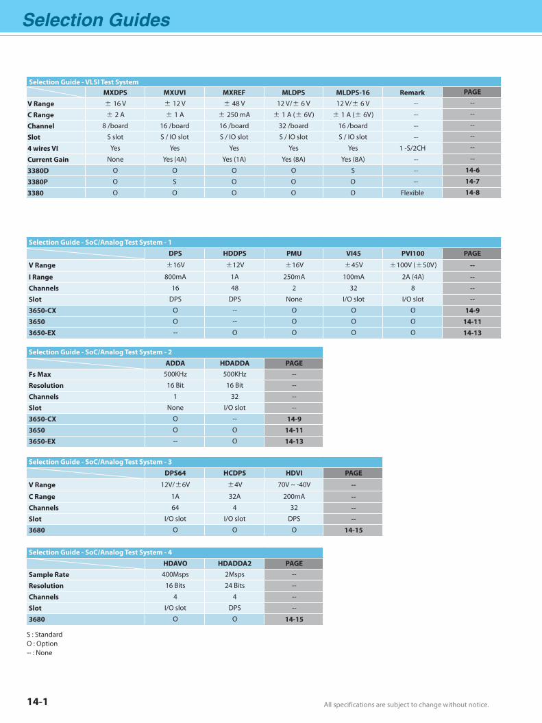
Selection Guides
All specifications are subject to change without notice. All specifications are subject to change without notice.14-1
Selection Guide - VLSI Test SystemMXDPS MXUVI MXREF MLDPS MLDPS-16 Remark PAGE
V Range ± 16 V ± 12 V ± 48 V 12 V/± 6 V 12 V/± 6 V -- --
C Range ± 2 A ± 1 A ± 250 mA ± 1 A (± 6V) ± 1 A (± 6V) -- --
Channel 8 /board 16 /board 16 /board 32 /board 16 /board -- --
Slot S slot S / IO slot S / IO slot S / IO slot S / IO slot -- --
4 wires VI Yes Yes Yes Yes Yes 1 -S/2CH --
Current Gain None Yes (4A) Yes (1A) Yes (8A) Yes (8A) -- --
3380D O O O O S -- 14-6
3380P O S O O O -- 14-7
3380 O O O O O Flexible 14-8
Selection Guide - SoC/Analog Test System - 2 ADDA HDADDA PAGEFs Max 500KHz 500KHz --
Resolution 16 Bit 16 Bit --
Channels 1 32 --
Slot None I/O slot --
3650-CX O -- 14-93650 O O 14-113650-EX -- O 14-13
Selection Guide - SoC/Analog Test System - 4 HDAVO HDADDA2 PAGESample Rate 400Msps 2Msps --
Resolution 16 Bits 24 Bits --
Channels 4 4 --
Slot I/O slot DPS --
3680 O O 14-15
Selection Guide - SoC/Analog Test System - 1 DPS HDDPS PMU VI45 PVI100 PAGE
V Range ±16V ±12V ±16V ±45V ±100V (±50V) --
I Range 800mA 1A 250mA 100mA 2A (4A) --Channels 16 48 2 32 8 --Slot DPS DPS None I/O slot I/O slot --3650-CX O -- O O O 14-93650 O -- O O O 14-113650-EX -- O O O O 14-13
Selection Guide - SoC/Analog Test System - 3 DPS64 HCDPS HDVI PAGE
V Range 12V/±6V ±4V 70V ~ -40V --
C Range 1A 32A 200mA --Channels 64 4 32 --Slot I/O slot I/O slot DPS --3680 O O O 14-15
S : Standard O : Option-- : None
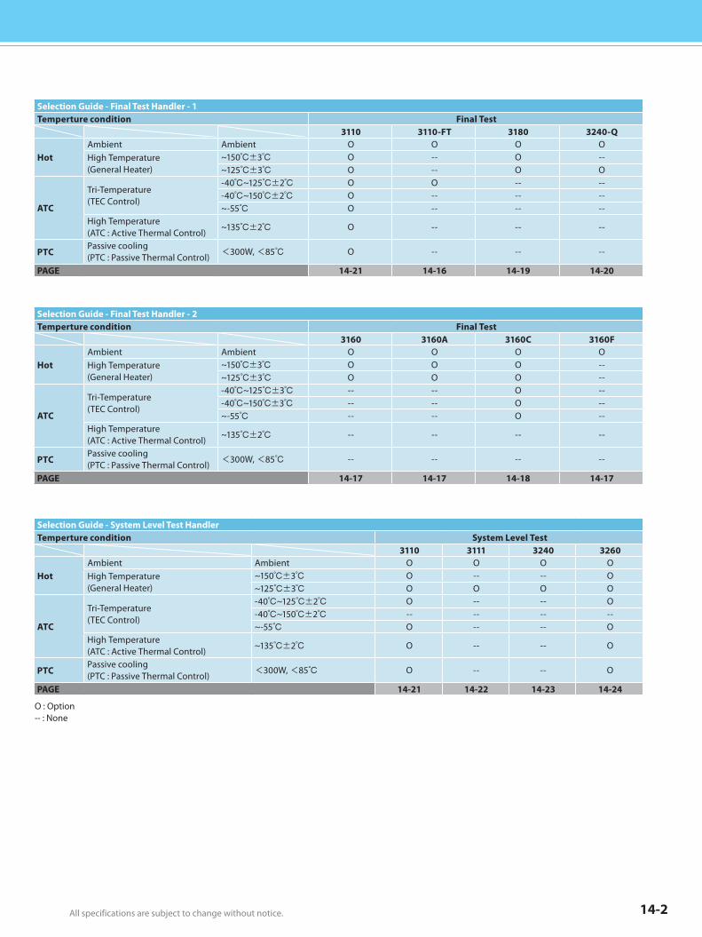
All specifications are subject to change without notice. All specifications are subject to change without notice. 14-2
O : Option-- : None
Selection Guide - Final Test Handler - 1Temperture condition Final Test
3110 3110-FT 3180 3240-Q
HotAmbient Ambient O O O OHigh Temperature(General Heater)
~150±3 O -- O --~125±3 O -- O O
ATC
Tri-Temperature (TEC Control)
-40~125±2 O O -- ---40~150±2 O -- -- --~-55 O -- -- --
High Temperature (ATC : Active Thermal Control)
~135±2 O -- -- --
PTCPassive cooling (PTC : Passive Thermal Control) <300W, <85 O -- -- --
PAGE 14-21 14-16 14-19 14-20
Selection Guide - System Level Test HandlerTemperture condition System Level Test
3110 3111 3240 3260
HotAmbient Ambient O O O OHigh Temperature(General Heater)
~150±3 O -- -- O~125±3 O O O O
ATC
Tri-Temperature (TEC Control)
-40~125±2 O -- -- O-40~150±2 -- -- -- --~-55 O -- -- O
High Temperature (ATC : Active Thermal Control)
~135±2 O -- -- O
PTCPassive cooling (PTC : Passive Thermal Control) <300W, <85 O -- -- O
PAGE 14-21 14-22 14-23 14-24
Selection Guide - Final Test Handler - 2Temperture condition Final Test
3160 3160A 3160C 3160F
HotAmbient Ambient O O O OHigh Temperature(General Heater)
~150±3 O O O --~125±3 O O O --
ATC
Tri-Temperature (TEC Control)
-40~125±3 -- -- O ---40~150±3 -- -- O --~-55 -- -- O --
High Temperature (ATC : Active Thermal Control)
~135±2 -- -- -- --
PTCPassive cooling (PTC : Passive Thermal Control) <300W, <85 -- -- -- --
PAGE 14-17 14-17 14-18 14-17
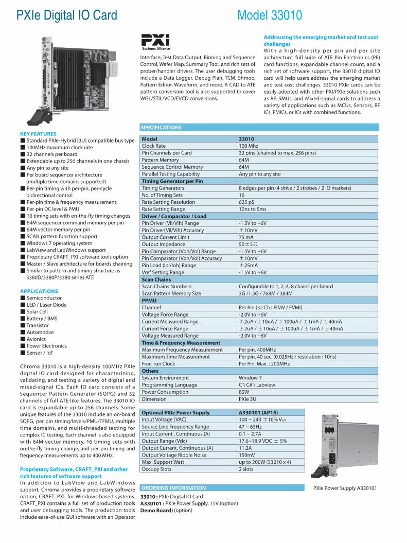
PXIe Digital IO Card Model 33010
KEY FEATURES Standard PXIe-Hybrid [3U] compatible bus type 100MHz maximum clock rate 32 channels per board Extendable up to 256 channels in one chassis Any pin to any site Per board sequencer architecture (multiple time domains supported) Per-pin timing with per-pin, per-cycle bidirectional control Per-pin time & frequency measurement Per-pin DC level & PMU 16 timing sets with on-the-fly timing changes 64M sequencer command memory per pin 64M vector memory per pin SCAN pattern function support Windows 7 operating system LabView and LabWindows support Proprietary CRAFT_PXI software tools option Master / Slave architecture for boards chaining Similar to pattern and timing structure as 3380D/3380P/3380 series ATE
APPLICATIONS Semiconductor LED / Laser Diode Solar Cell Battery / BMS Transistor Automotive Avionics Power Electronics Sensor / IoT
Chroma 33010 is a high-density 100MHz PXIe digital IO card designed for characterizing, validating, and testing a variety of digital and mixed-signal ICs. Each IO card consists of a Sequencer Pattern Generator (SQPG) and 32 channels of full ATE-like features. The 33010 IO card is expandable up to 256 channels. Some unique features of the 33010 include an on-board SQPG, per pin timing/levels/PMU/TFMU, multiple time domains, and multi-threaded testing for complex IC testing. Each channel is also equipped with 64M vector memory, 16 timing sets with on-the-fly timing change, and per pin timing and frequency measurements up to 400 MHz.
Proprietary Software, CRAFT_PXI and other rich features of software supportI n a d d i t i o n to L a b Vi e w a n d L a b Wi n d ows support, Chroma provides a proprietary software option, CRAFT_PXI, for Windows-based systems. CRAFT_PXI contains a full set of production tools and user debugging tools. The production tools include ease-of-use GUI software with an Operator
Interface, Test Data Output, Binning and Sequence Control, Wafer Map, Summary Tool, and rich sets of prober/handler drivers. The user debugging tools include a Data Logger, Debug Plan, TCM, Shmoo, Pattern Editor, Waveform, and more. A CAD to ATE pattern conversion tool is also supported to cover WGL/STIL/VCD/EVCD conversions.
ORDERING INFORMATION
33010 : PXIe Digital IO CardA330101 : PXIe Power Supply, 15V (option)Demo Board) (option)
Addressing the emerging market and test costchallengesWi t h a h i g h-d e n s i t y p e r p i n a n d p e r s i t e architecture, full suite of ATE Pin Electronics (PE) card functions, expandable channel count, and a rich set of software support, the 33010 digital IO card will help users address the emerging market and test cost challenges. 33010 PXIe cards can be easily adopted with other PXI/PXIe solutions such as RF, SMUs, and Mixed-signal cards to address a variety of applications such as MCUs, Sensors, RF ICs, PMICs, or ICs with combined functions.
Systems Alliance
SPECIFICATIONS
PXIe Power Supply A330101
Model 33010Clock Rate 100 MhzPin Channels per Card 32 pins (chained to max. 256 pins)Pattern Memory 64MSequence Control Memory 64MParallel Testing Capability Any pin to any siteTiming Generator per PinTiming Generators 8 edges per pin (4 drive / 2 strobes / 2 IO markers)No. of Timing Sets 16Rate Setting Resolution 625 pSRate Setting Range 10ns to 5ms Driver / Comparator / LoadPin Driver (Vil/Vih) Range -1.5V to +6VPin Driver(Vil/Vih) Accuracy ±10mVOutput Current Limit 75 mAOutput Impedance 50±5ΩPin Comparator (Voh/Vol) Range -1.5V to +6VPin Comparator (Voh/Vol) Accuracy ±10mVPin Load (Iol/Ioh) Range ±25mAVref Setting Range -1.5V to +6VScan ChainsScan Chains Numbers Configurable to 1, 2, 4, 8 chains per boardScan Pattern Memory Size 3G /1.5G / 768M / 384MPPMUChannel Per Pin (32 Chs FIMV / FVMI)Voltage Force Range -2.0V to +6VCurrent Measured Range ±2uA /±10uA / ±100uA / ±1mA / ±40mACurrent Force Range ±2uA / ±10uA / ±100uA / ±1mA / ±40mAVoltage Measured Range -2.0V to +6VTime & Frequency MeasurementMaximum Frequency Measurement Per pin, 400MHzMaximum Time Measurement Per pin, 40 sec. (0.025Hz / resolution : 10ns)Free-run Clock Per Pin, Max. : 200MHzOthersSystem Environment Window 7Programming Language C \ C# \ LabviewPower Consumption 80WDimension PXIe 3U
Optional PXIe Power Supply A330101 (AP15)Input Voltage (VAC) 100 ~ 240 ±10% VLN
Source Line Frequency Range 47 ~ 63HzInput Current , Continuous (A) 0.1 ~ 2.7AOutput Range (Vdc) 17.6~18.9 VDC ± 5%Output Current, Continuous (A) 11.2AOutput Voltage Ripple Noise 150mVMax. Support Watt up to 200W (33010 x 4)Occupy Slots 2 slots
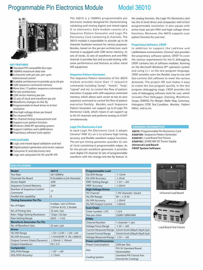
Programmable Pin Electronics Module Model 36010
KEY FEATURES Standard PXI compatible Bus type 100MHz maximum data rate 8 channels with per-pin, per-cycle bidirectional control Scalable architecture to provide up to 64-pin 32M sequence command memory More than 17 pattern sequence commands Per-pin architecture 32M vector memory per pin 32 sets of clock and waveform per pin Waveforms changes on-the-fly Programmable tri-level driver in 610uV resolution One high voltage driver per board Per-channel PMU Per-channel timing measurement unit Support scan pattern function Windows 2000/XP operating system Support LabView and LabWindows Proprietary software tools option
APPLICATIONS Logic and mixed signal validation and test Digital pattern generator and vector capture Consumer IC and electronics test Logic test subsystem for DC and RF ATE
The 36010 is a 100MHz programmable pin electronic module designed for characterizing, validating and testing digital and mixed signal IC or electronics. Each module consists of a Sequence Pattern Generator and Logic Pin Electronics Card containing 8 channels. The 36010 module is expandable to provide up to 64 channels hardware resource for various purposes. Besides, based on the per-pin architecture, each channel is equipped with 32M vector memory, 32 sets of clocks, 32 sets of waveforms and one PMU channel. It provides fast and accurate testing, with same performance and features as other stand ATE equipment.
Sequence Pattern Generator The Sequence Pattern Generator of the 36010 module provides more than 17 sequence commands including "jump", "match", "loop", "repeat" and etc. to control the flow of pattern execution. It equips with 32M sequence command memory, which allows each vector to has its own sequence command to control the flow of pattern execution flexibly. Besides, each Sequence Pattern Generator can support up to 8 Logic Pin Electronics Cards, which means it can support up to 64 I/O channels and performs testing on 8 DUT simultaneously.
Logic Pin Electronics CardIn each Logic Pin Electronics Card, it adopts Chroma® PINF ICs on it to achieve high timing accuracy and flexible waveform output functions. The per-pin timing generator provides 32 sets of clock containing 6 programmable edges. As for the per-pin waveform generator, it provides each digital I/O channel 32 sets of programmable waveform with the change-one-the-fly feature. In
ORDERING INFORMATION
36010 : Programmable Pin Electronics CardA360100 : Sequence Pattern GeneratorA360101 : Load Board Test FixtureA360102 : 250W/48V DC Power SupplyUniversal Load BoardCRISP System Software
Load Board Test Fixture
Universal Load Board
Model 36010Test Rate 50/100MHzChannels Per Board 8 (Scalable to 64 channels)Vector Depth 32MSequence Control Memory 32MNumber of Sequence ControlCommand
17
Parallel test capability 8Timing Generator Per Pin
No. of Edges6 edges / pin (2 Driver, 2 Driver & I/O, 2 Strobe)
No. of Timing Sets 32 sets / pinRate / Edge Setting Resolution 125ps / 62.5psRate Setting Range 20nS → 1mSWaveform Generator Per PinNo. of Waveform Sets 32 sets / pinDriverVIL/VIH Range -1.5V~+5.9V / -1.4V~+6VVIL/VIH Accuracy ±5mV@VIH ≧ VIL+200mVOutput Current (Static/Dynamic) ±50mA/±100mAOutput Impedance 50±5ΩComparatorVOL/VOH Range -1.5V ~ +6VVOL/VOH Accuracy ±15mV
Programmable LoadIOL/IOH Range ±12mAIOL/IOH Accuracy ±25uAVREF Setting Range -1.5V ~ +6VVREF Accuracy ±50mVHigh Voltage DriverHV Channel 1 HV channels / boardVIL/VIH Range 0V ~ +13.5VVIL/VIH Accuracy ±20mVVIL/VIH Output Current ±60mAScan ChainChain number / LPC 1/2/4Size per chain 256M/128M/64MPPMUChannel Number 1 channel / 1 pinVoltage Force Range -1.5V ~ +6VCurrent Measured Range 32mA/2mA/200µA/20µA/2µACurrent Forced Range 32mA/2mA/200µA/20µA/2µAVoltage Measured Range -1.5V ~ +6VPower and DimensionsPower Consumption 25W per Slot
SizePXI 3U Standard Board(Extendable)
Cooling SystemStandard PXI Chassis Fan (Forced Air Cooling)
SPECIFICATIONS
the analog function, the Logic Pin Electronics card has the tri-level driver and comparator with 610uV programmable resolution. It also equips with active load, per-pin PMU and high voltage driver functions. Moreover, the 36010 supports scan pattern function for scan test.
Proprietary Software, CRISPI n a d d i t i o n t o s u p p o r t t h e L a b V i e w a n d LabWindows environments, Chroma® also provides the proprietary software option, CRISP. To cover the various requirements for the IC debugging, CRISP contains lots of software modules. Running on the Microsoft Windows XP® operation system and using C++ as the test program language, CRISP provides users the flexible, easy-to-use and fast-runtime GUI software to meet the various demands. The project IDE tool makes it easy to create the test program quickly. In the test program debugging stage, CRISP provides the suite of debugging software tools for user, which includes Plan Debugger, Datalog, Waveform, Scope, SHMOO, Pin Margin, Wafer Map, Summary, Histogram, STDF, Test Condition Monitor, Pattern Editor, and so on.
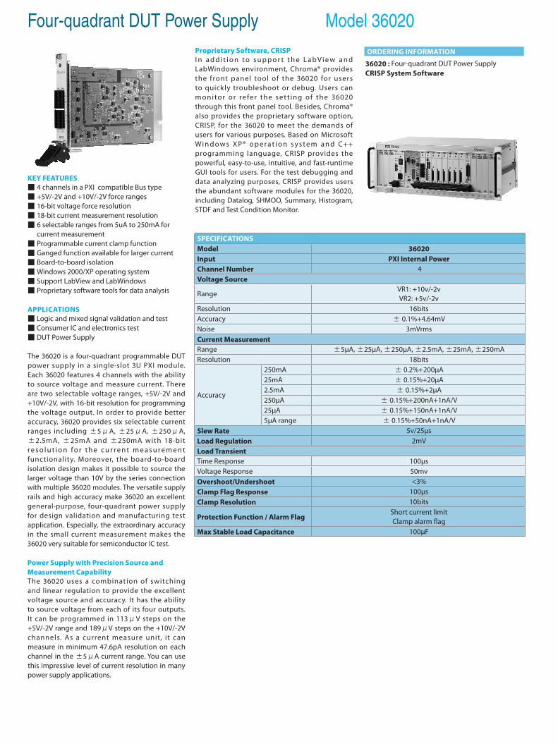
Four-quadrant DUT Power Supply Model 36020
SPECIFICATIONSModel 36020Input PXI Internal PowerChannel Number 4Voltage Source
Range VR1: +10v/-2vVR2: +5v/-2v
Resolution 16bitsAccuracy ± 0.1%+4.64mVNoise 3mVrmsCurrent MeasurementRange ±5µA, ±25µA, ±250µA, ±2.5mA, ±25mA, ±250mAResolution 18bits
Accuracy
250mA ± 0.2%+200µA25mA ± 0.15%+20µA2.5mA ± 0.15%+2µA250µA ± 0.15%+200nA+1nA/V25µA ± 0.15%+150nA+1nA/V5µA range ± 0.15%+50nA+1nA/V
Slew Rate 5v/25µsLoad Regulation 2mVLoad TransientTime Response 100µsVoltage Response 50mvOvershoot/Undershoot <3%Clamp Flag Response 100µsClamp Resolution 10bits
Protection Function / Alarm FlagShort current limitClamp alarm flag
Max Stable Load Capacitance 100µF
KEY FEATURES 4 channels in a PXI compatible Bus type +5V/-2V and +10V/-2V force ranges 16-bit voltage force resolution 18-bit current measurement resolution 6 selectable ranges from 5uA to 250mA for
current measurement Programmable current clamp function Ganged function available for larger current Board-to-board isolation Windows 2000/XP operating system Support LabView and LabWindows Proprietary software tools for data analysis
APPLICATIONS Logic and mixed signal validation and test Consumer IC and electronics test DUT Power Supply
The 36020 is a four-quadrant programmable DUT power supply in a single-slot 3U PXI module. Each 36020 features 4 channels with the ability to source voltage and measure current. There are two selectable voltage ranges, +5V/-2V and +10V/-2V, with 16-bit resolution for programming the voltage output. In order to provide better accuracy, 36020 provides six selectable current ranges including ±5μA, ±25μA, ±250μA, ±2.5mA, ±25mA and ±250mA with 18-bit r e s o l u t i o n fo r t h e c u r r e n t m e a s u r e m e n t functionality. Moreover, the board-to-board isolation design makes it possible to source the larger voltage than 10V by the series connection with multiple 36020 modules. The versatile supply rails and high accuracy make 36020 an excellent general-purpose, four-quadrant power supply for design validation and manufacturing test application. Especially, the extraordinary accuracy in the small current measurement makes the 36020 very suitable for semiconductor IC test.
Power Supply with Precision Source and Measurement CapabilityThe 36020 uses a combinat ion of switching and linear regulation to provide the excellent voltage source and accuracy. It has the ability to source voltage from each of its four outputs. It can be programmed in 113μV steps on the +5V/-2V range and 189μV steps on the +10V/-2V channels. As a current measure unit, it can measure in minimum 47.6pA resolution on each channel in the ±5μA current range. You can use this impressive level of current resolution in many power supply applications.
Proprietary Software, CRISPI n a d d i t i o n t o s u p p o r t t h e L a b Vi e w a n d LabWindows environment, Chroma® provides the front panel tool of the 36020 for users to quickly troubleshoot or debug. Users can monitor or refer the sett ing of the 36020 through this front panel tool. Besides, Chroma® also provides the proprietary software option, CRISP, for the 36020 to meet the demands of users for various purposes. Based on Microsoft Wi n d o w s X P® o p e r a t i o n s y s t e m a n d C++ programming language, CRISP provides the powerful, easy-to-use, intuitive, and fast-runtime GUI tools for users. For the test debugging and data analyzing purposes, CRISP provides users the abundant software modules for the 36020, including Datalog, SHMOO, Summary, Histogram, STDF and Test Condition Monitor.
ORDERING INFORMATION
36020 : Four-quadrant DUT Power SupplyCRISP System Software
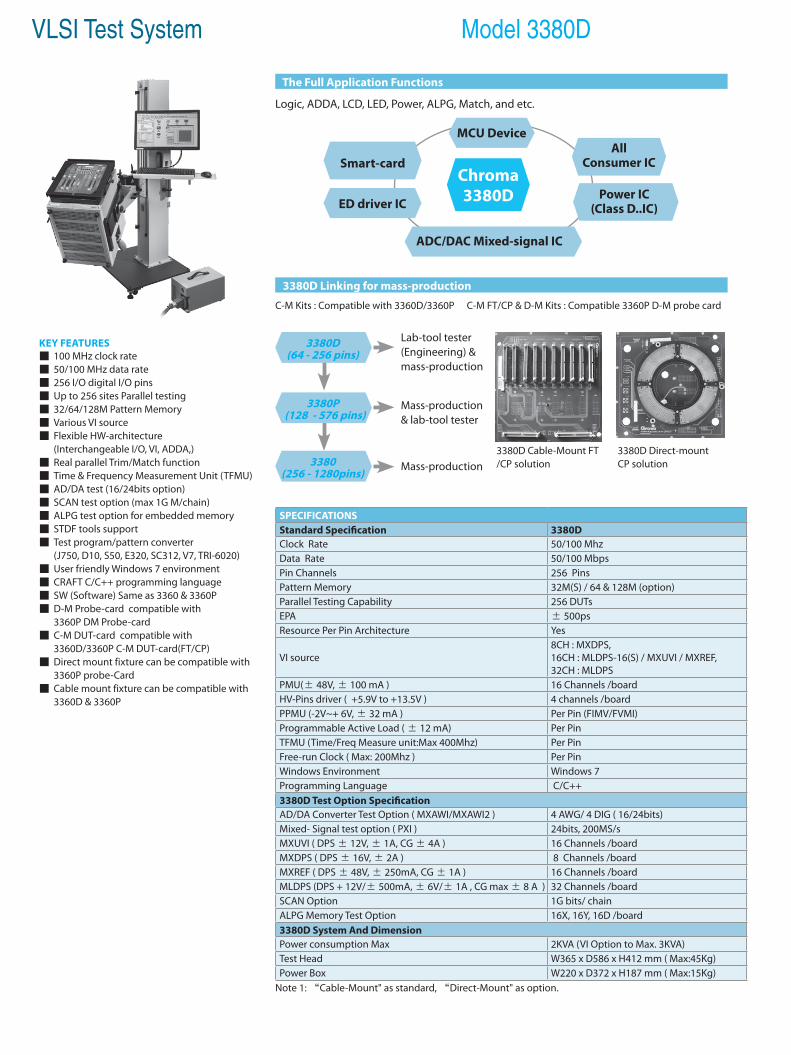
VLSI Test System Model 3380D
3380D Cable-Mount FT/CP solution
3380D Direct-mountCP solution
KEY FEATURES 100 MHz clock rate 50/100 MHz data rate 256 I/O digital I/O pins Up to 256 sites Parallel testing 32/64/128M Pattern Memory Various VI source Flexible HW-architecture (Interchangeable I/O, VI, ADDA,) Real parallel Trim/Match function Time & Frequency Measurement Unit (TFMU) AD/DA test (16/24bits option) SCAN test option (max 1G M/chain) ALPG test option for embedded memory STDF tools support Test program/pattern converter (J750, D10, S50, E320, SC312, V7, TRI-6020) User friendly Windows 7 environment CRAFT C/C++ programming language SW (Software) Same as 3360 & 3360P D-M Probe-card compatible with 3360P DM Probe-card C-M DUT-card compatible with 3360D/3360P C-M DUT-card(FT/CP) Direct mount fixture can be compatible with 3360P probe-Card Cable mount fixture can be compatible with 3360D & 3360P
MCU Device
Chroma 3380D
ADC/DAC Mixed-signal IC
ED driver IC
Smart-cardAll
Consumer IC
Power IC(Class D..IC)
The Full Application Functions
3380D Linking for mass-production
Logic, ADDA, LCD, LED, Power, ALPG, Match, and etc.
C-M Kits : Compatible with 3360D/3360P C-M FT/CP & D-M Kits : Compatible 3360P D-M probe card
Note 1: “Cable-Mount" as standard, “Direct-Mount" as option.
SPECIFICATIONSStandard Specification 3380D Clock Rate 50/100 Mhz Data Rate 50/100 MbpsPin Channels 256 Pins Pattern Memory 32M(S) / 64 & 128M (option) Parallel Testing Capability 256 DUTs EPA ± 500ps Resource Per Pin Architecture Yes
VI source 8CH : MXDPS, 16CH : MLDPS-16(S) / MXUVI / MXREF, 32CH : MLDPS
PMU(± 48V, ± 100 mA ) 16 Channels /board HV-Pins driver ( +5.9V to +13.5V ) 4 channels /board PPMU (-2V~+ 6V, ± 32 mA ) Per Pin (FIMV/FVMI) Programmable Active Load ( ± 12 mA) Per Pin TFMU (Time/Freq Measure unit:Max 400Mhz) Per Pin Free-run Clock ( Max: 200Mhz ) Per Pin Windows Environment Windows 7 Programming Language C/C++ 3380D Test Option Specification AD/DA Converter Test Option ( MXAWI/MXAWI2 ) 4 AWG/ 4 DIG ( 16/24bits) Mixed- Signal test option ( PXI ) 24bits, 200MS/s MXUVI ( DPS ± 12V, ± 1A, CG ± 4A ) 16 Channels /board MXDPS ( DPS ± 16V, ± 2A ) 8 Channels /board MXREF ( DPS ± 48V, ± 250mA, CG ± 1A ) 16 Channels /board MLDPS (DPS + 12V/± 500mA, ± 6V/± 1A , CG max ± 8 A ) 32 Channels /boardSCAN Option 1G bits/ chain ALPG Memory Test Option 16X, 16Y, 16D /board 3380D System And Dimension Power consumption Max 2KVA (VI Option to Max. 3KVA)Test Head W365 x D586 x H412 mm ( Max:45Kg) Power Box W220 x D372 x H187 mm ( Max:15Kg)
3380D (64 - 256 pins)
Lab-tool tester (Engineering) & mass-production
3380P (128 - 576 pins)
Mass-production& lab-tool tester
3380 (256 - 1280pins) Mass-production
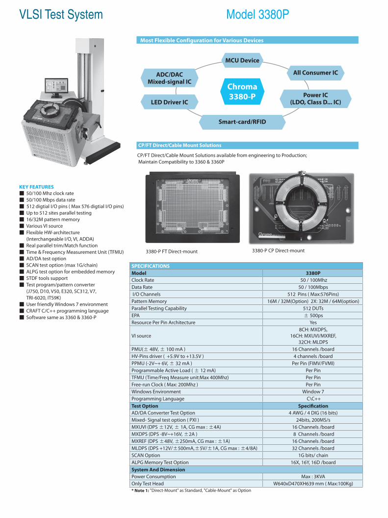
KEY FEATURES 50/100 Mhz clock rate 50/100 Mbps data rate 512 digtial I/O pins ( Max 576 digtial I/O pins) Up to 512 sites parallel testing 16/32M pattern memory Various VI source Flexible HW-architecture (Interchangeable I/O, VI, ADDA) Real parallel trim/Match function Time & Frequency Measurement Unit (TFMU) AD/DA test option SCAN test option (max 1G/chain) ALPG test option for embedded memory STDF tools support Test program/pattern converter (J750, D10, V50, E320, SC312, V7, TRI-6020, ITS9K) User friendly Windows 7 environment CRAFT C/C++ programming language Software same as 3360 & 3360-P
VLSI Test System Model 3380P
3380-P FT Direct-mount
MCU Device
Chroma 3380-P
ADC/DAC Mixed-signal IC
LED Driver IC
Smart-card/RFID
All Consumer IC
Power IC(LDO, Class D... IC)
Most Flexible Configuration for Various Devices
CP/FT Direct/Cable Mount Solutions
3380-P CP Direct-mount
CP/FT Direct/Cable Mount Solutions available from engineering to Production; Maintain Compatibility to 3360 & 3360P
SPECIFICATIONSModel 3380PClock Rate 50 / 100MhzData Rate 50 / 100Mbps I/O Channels 512 Pins ( Max:576Pins)Pattern Memory 16M / 32M(Option) 2X: 32M / 64M(option)Parallel Testing Capability 512 DUTsEPA ± 500psResource Per Pin Architecture Yes
VI source 8CH: MXDPS,
16CH: MXUVI/MXREF, 32CH: MLDPS
PMU(± 48V, ± 100 mA ) 16 Channels /boardHV-Pins driver ( +5.9V to +13.5V ) 4 channels /boardPPMU (-2V~+ 6V, ± 32 mA ) Per Pin (FIMV/FVMI)Programmable Active Load ( ± 12 mA) Per PinTFMU (Time/Freq Measure unit:Max 400Mhz) Per PinFree-run Clock ( Max: 200Mhz ) Per PinWindows Environment Window 7Programming Language C\C++Test Option SpecificationAD/DA Converter Test Option 4 AWG / 4 DIG (16 bits)Mixed- Signal test option ( PXI ) 24bits, 200MS/s MXUVI (DPS ±12V, ± 1A, CG max : ±4A) 16 Channels /boardMXDPS (DPS -8V~+16V, ±2A ) 8 Channels /boardMXREF (DPS ±48V, ±250mA, CG max : ±1A) 16 Channels /boardMLDPS (DPS +12V/±500mA,±5V/±1A, CG max : ±4/8A) 32 Channels /boardSCAN Option 1G bits/ chainALPG Memory Test Option 16X, 16Y, 16D /boardSystem And DimensionPower Consumption Max : 3KVAOnly Test Head W640xD470XH639 mm ( Max:100Kg)* Note 1: "Direct-Mount" as Standard, "Cable-Mount" as Option
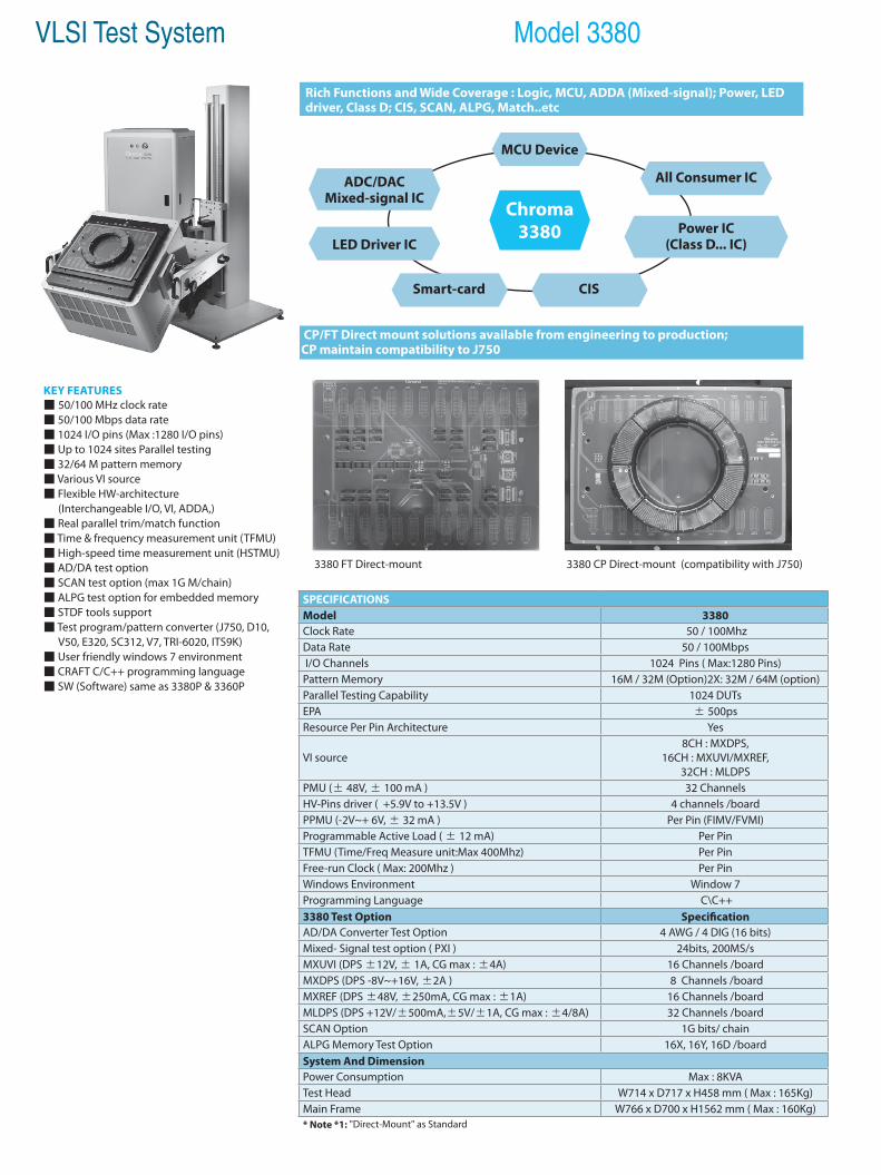
VLSI Test System Model 3380
KEY FEATURES 50/100 MHz clock rate 50/100 Mbps data rate 1024 I/O pins (Max :1280 I/O pins) Up to 1024 sites Parallel testing 32/64 M pattern memory Various VI source Flexible HW-architecture (Interchangeable I/O, VI, ADDA,) Real parallel trim/match function Time & frequency measurement unit (TFMU) High-speed time measurement unit (HSTMU) AD/DA test option SCAN test option (max 1G M/chain) ALPG test option for embedded memory STDF tools support Test program/pattern converter (J750, D10, V50, E320, SC312, V7, TRI-6020, ITS9K) User friendly windows 7 environment CRAFT C/C++ programming language SW (Software) same as 3380P & 3360P
3380 FT Direct-mount
MCU Device
Chroma 3380
ADC/DAC Mixed-signal IC
LED Driver IC
Smart-card CIS
All Consumer IC
Power IC(Class D... IC)
Rich Functions and Wide Coverage : Logic, MCU, ADDA (Mixed-signal); Power, LED driver, Class D; CIS, SCAN, ALPG, Match..etc
CP/FT Direct mount solutions available from engineering to production;CP maintain compatibility to J750
3380 CP Direct-mount (compatibility with J750)
SPECIFICATIONSModel 3380Clock Rate 50 / 100MhzData Rate 50 / 100Mbps I/O Channels 1024 Pins ( Max:1280 Pins) Pattern Memory 16M / 32M (Option)2X: 32M / 64M (option)Parallel Testing Capability 1024 DUTsEPA ± 500psResource Per Pin Architecture Yes
VI source 8CH : MXDPS,
16CH : MXUVI/MXREF, 32CH : MLDPS
PMU (± 48V, ± 100 mA ) 32 ChannelsHV-Pins driver ( +5.9V to +13.5V ) 4 channels /boardPPMU (-2V~+ 6V, ± 32 mA ) Per Pin (FIMV/FVMI)Programmable Active Load ( ± 12 mA) Per PinTFMU (Time/Freq Measure unit:Max 400Mhz) Per PinFree-run Clock ( Max: 200Mhz ) Per PinWindows Environment Window 7Programming Language C\C++3380 Test Option SpecificationAD/DA Converter Test Option 4 AWG / 4 DIG (16 bits)Mixed- Signal test option ( PXI ) 24bits, 200MS/s MXUVI (DPS ±12V, ± 1A, CG max : ±4A) 16 Channels /boardMXDPS (DPS -8V~+16V, ±2A ) 8 Channels /boardMXREF (DPS ±48V, ±250mA, CG max : ±1A) 16 Channels /boardMLDPS (DPS +12V/±500mA,±5V/±1A, CG max : ±4/8A) 32 Channels /boardSCAN Option 1G bits/ chainALPG Memory Test Option 16X, 16Y, 16D /boardSystem And DimensionPower Consumption Max : 8KVATest Head W714 x D717 x H458 mm ( Max : 165Kg) Main Frame W766 x D700 x H1562 mm ( Max : 160Kg) * Note *1: "Direct-Mount" as Standard
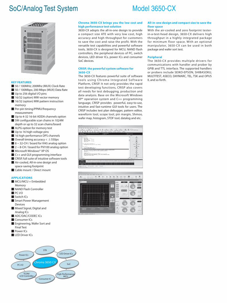
SoC/Analog Test System Model 3650-CX
KEY FEATURES 50 / 100MHz; 200Mhz (MUX) Clock Rate 50 / 100Mbps; 200 Mbps (MUX) Data Rate Up to 256 digital I/O pins 16/32 (option) MW vector memory 16/32 (option) MW pattern instruction memory Per-pin timing/PPMU/frequency measurement Up to 4-32 16-bit ADDA channels option SW configurable scan chains in 1024M depth or up to 32 scan chains/board ALPG option for memory test Up to 16 high-voltage pins 16 high-performance DPS channels Overall timing accuracy < ±550ps 8 ~ 32-CH / board for VI45 analog option 2 ~ 8-CH / board for PVI100 analog option Microsoft Windows® XP OS C++ and GUI programming interface CRISP, full suite of intuitive software tools Air-cooled, All-in-one design and space-saving footprint Cable mount / Direct mount
APPLICATIONS MCU/MCU + Embedded Memory NAND Flash Controller PC I/O Switch ICs Smart Power Management Devices Mixed Signal, Digital and Analog ICs ADC/DAC/CODEC ICs Consumer ICs Engineering, Wafer Sort and Final Test Power ICs LED Driver ICs
Chroma 3650-CX brings you the low cost and high performance test solution 3650-CX adopts the all-in-one design to provide a compact size ATE with very low cost, high accuracy and high throughput for customers to save the cost and raise the profit. With the versatile test capabilities and powerful software tools, 3650-CX is designed for MCU, NAND flash controllers, the peripheral devices of PC, switch devices, LED driver ICs, power ICs and consumer SoC devices.
CRISP, the powerful system software for 3650-CXThe 3650-CX features powerful suite of software t o o l s u s i n g C h ro m a I n t e g r a t e d S o f t w a re Platform, CRISP. It not only provides the rapid test developing functions, CRISP also covers all needs for test debugging, production and data analysis. Base on the Microsoft Windows XP® operation system and C++ programming language, CRISP provides powerful, easy-to-use, intuitive and fast-runtime GUI tools for users. The CRISP includes test plan debugger, pattern editor, waveform tool, scope tool, pin margin, Shmoo, wafer map, histogram, STDF tool, datalog and etc.
All-in-one design and compact size to save the floor spaceWith the air-cooled and zero footprint tester-in-a-test-head design, 3650-CX delivers high throughput in a highly integrated package for minimum floor space. With an optional manipulator, 3650-CX can be used in both package and wafer sort test.
PeripheralThe 3650-CX provides mult iple dr ivers for communications with handler and prober by GPIB and TTL interface. The supported handlers or probers include SEIKO-EPSON, SHIBASOKU, MULTITEST, ASECO, DAYMARC, TEL, TSK and OPUS II, and so forth.
Chroma 3650-CXPC I/O
TCON/LCD Controller
SoC
STB
Consumer IC
High Performance MCU
Power ICs LED Driver ICs
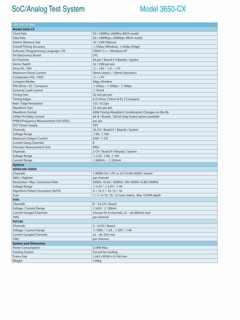
SoC/Analog Test System Model 3650-CX
SPECIFICATIONSModel 3650-CXClock Rate 50 / 100Mhz; 200Mhz (MUX mode)Data Rate 50 / 100Mbps; 200Mbps (MUX mode)Pattern Memory Size 16 / 32M (Option)Overall Timing Accuracy ±550ps (Window), ±450ps (Edge)Software /Programming Language / OS CRISP/ C++ / Windows XPPin Electronics Board LPCIO Channels 64-pin / Board X 4 Boards / SystemVector Depth 16 / 32M per pinDrive VIL / VIH -2 ~ +6V / -1.9 ~ +7VMaximum Driver Current 50mA (static) / 100mA (dynamic)Comparator VOL / VOH -2 ~ +7VCompare Modes Edge, WindowEPA (Drive / IO / Compare) ±300ps / ±300ps / ±300psDynamic Load Current ±35mATiming Sets 32 sets per pinTiming Edges 6 (2 Drive, 2 Drive & IO, 2 Compare)Rate / Edge Resolution 125 / 62.5psWaveform Sets 32 sets per pinWaveform Format 4096 Timing-Waveform Combination Changes on-the-flyUtility Pin Relay Control 64 (8 / Board), 128 bit relay board option availablePPMU/Frequency Measurement Unit (OSC) per pinDUT Power Supply DPSChannels 16-CH / Board X 1 Boards / SystemVoltage Range ±8V, ±16VMaximum Output Current 0.8A / 1-CHCurrent Gang Channels 8Precision Measurement Unit PMUChannels 2-CH / Board X 4 Boards / SystemVoltage Range ±2.5V, ±8V, ±16VCurrent Range ±800nA ~ ±250mAOptionsADDA/HD-ADDAChannels 1 ADDA CH / LPC or 32 CH HD-ADDA / boardAWG / Digitizer per channelResolution / Max. Conversion Rate ADDA: 16-bit / 500KHz ; HD-ADDA: 16 Bit 500KHzVoltage Range ±2.5V / ±4.5V / ±9VAlgorithm Pattern Generator (ALPG) X = 16, Y = 16 / D = 16Scan 1 / 2 / 4 / 8 / 16 / 32 scan chains, Max 1024M depthVI45Channels 8 ~ 32-CH / BoardVoltage / Current Range ±45V / ±100mACurrent Ganged Channels 4 buses for 8 channels, x2 – x8, 800mA maxTMU per channelPVI100Channels 2 ~ 8-CH / BoardVoltage / Current Range ±100V / ±2A , ±50V / ±4ACurrent Ganged Channels x2 – x8, 32A maxTMU per channelSystem and DimensionPower Consumption 3.5KW MaxCooling System Forced Air CoolingFrame Size L 643 x W369 x H 760 mmWeight 130Kg
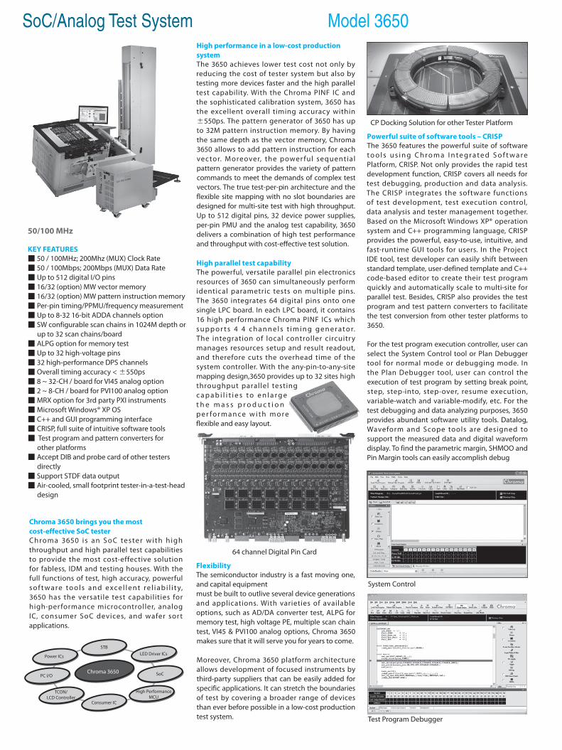
Chroma 3650 brings you the most cost-effective SoC testerChroma 3650 is an S oC tester with h igh throughput and high parallel test capabilities to provide the most cost-effective solution for fabless, IDM and testing houses. With the full functions of test, high accuracy, powerful s o f t wa re to o l s a n d exce l l e nt re l i a b i l i t y, 3650 has the versatile test capabilities for high-performance microcontroller, analog IC, consumer SoC devices, and wafer sort applications.
Chroma 3650PC I/O
TCON/LCD Controller
SoC
STB
Consumer IC
High Performance MCU
Power ICs LED Driver ICs
50/100 MHz
KEY FEATURES 50 / 100MHz; 200Mhz (MUX) Clock Rate 50 / 100Mbps; 200Mbps (MUX) Data Rate Up to 512 digital I/O pins 16/32 (option) MW vector memory 16/32 (option) MW pattern instruction memory Per-pin timing/PPMU/frequency measurement Up to 8-32 16-bit ADDA channels option SW configurable scan chains in 1024M depth or up to 32 scan chains/board ALPG option for memory test Up to 32 high-voltage pins 32 high-performance DPS channels Overall timing accuracy < ±550ps 8 ~ 32-CH / board for VI45 analog option 2 ~ 8-CH / board for PVI100 analog option MRX option for 3rd party PXI instruments Microsoft Windows® XP OS C++ and GUI programming interface CRISP, full suite of intuitive software tools Test program and pattern converters for other platforms Accept DIB and probe card of other testers directly Support STDF data output Air-cooled, small footprint tester-in-a-test-head design
High performance in a low-cost production systemThe 3650 achieves lower test cost not only by reducing the cost of tester system but also by testing more devices faster and the high parallel test capability. With the Chroma PINF IC and the sophisticated calibration system, 3650 has the excellent overall timing accuracy within ±550ps. The pattern generator of 3650 has up to 32M pattern instruction memory. By having the same depth as the vector memory, Chroma 3650 allows to add pattern instruction for each vector. Moreover, the power ful sequential pattern generator provides the variety of pattern commands to meet the demands of complex test vectors. The true test-per-pin architecture and the flexible site mapping with no slot boundaries are designed for multi-site test with high throughput. Up to 512 digital pins, 32 device power supplies, per-pin PMU and the analog test capability, 3650 delivers a combination of high test performance and throughput with cost-effective test solution.
High parallel test capabilityThe powerful, versatile parallel pin electronics resources of 3650 can simultaneously perform identical parametric tests on multiple pins. The 3650 integrates 64 digital pins onto one single LPC board. In each LPC board, it contains 16 high performance Chroma PINF ICs which s u p p o r t s 4 4 c h a n n e l s t i m i n g g e n e r a t o r. The integration of local controller circuitry manages resources setup and result readout, and therefore cuts the overhead time of the system controller. With the any-pin-to-any-site mapping design,3650 provides up to 32 sites high throughput parallel testing c a p a b i l i t i e s t o e n l a r g e t h e m a s s p r o d u c t i o n p e r fo r m a n c e w i t h m o re flexible and easy layout.
FlexibilityThe semiconductor industry is a fast moving one, and capital equipmentmust be built to outlive several device generations and applications. With varieties of available options, such as AD/DA converter test, ALPG for memory test, high voltage PE, multiple scan chain test, VI45 & PVI100 analog options, Chroma 3650 makes sure that it will serve you for years to come.
Moreover, Chroma 3650 platform architecture allows development of focused instruments by third-party suppliers that can be easily added for specific applications. It can stretch the boundaries of test by covering a broader range of devices than ever before possible in a low-cost production test system.
System Control
64 channel Digital Pin Card
SoC/Analog Test System Model 3650
Powerful suite of software tools – CRISPThe 3650 features the powerful suite of software t o o l s u s i n g C h r o m a I n t e g r a t e d S o f t w a r e Platform, CRISP. Not only provides the rapid test development function, CRISP covers all needs for test debugging, production and data analysis. The CRISP integrates the software functions of test development, test execution control, data analysis and tester management together. Based on the Microsoft Windows XP® operation system and C++ programming language, CRISP provides the powerful, easy-to-use, intuitive, and fast-runtime GUI tools for users. In the Project IDE tool, test developer can easily shift between standard template, user-defined template and C++ code-based editor to create their test program quickly and automatically scale to multi-site for parallel test. Besides, CRISP also provides the test program and test pattern converters to facilitate the test conversion from other tester platforms to 3650.
For the test program execution controller, user can select the System Control tool or Plan Debugger tool for normal mode or debugging mode. In the Plan Debugger tool, user can control the execution of test program by setting break point, step, step-into, step-over, resume execution, variable-watch and variable-modify, etc. For the test debugging and data analyzing purposes, 3650 provides abundant software utility tools. Datalog, Waveform and Scope tools are designed to support the measured data and digital waveform display. To find the parametric margin, SHMOO and Pin Margin tools can easily accomplish debug
Test Program Debugger
CP Docking Solution for other Tester Platform

SoC/Analog Test System Model 3650
by auto-mode or manual-mode execution. Besides, the Wafer Map, Summary, Histogram and STDF tools are very helpful and powerful for collecting the test results and analyzing the parametric characterization. As for the Test Condition Monitor and Pattern Editor tools, they provide the superior functions for run-time debugging to change the test conditions or pattern data without breaking the test or modifying the source files. Besides, CRISP also prepares the ADDA tool and Bit Map tool for the analog and ALPG option. Using the ADDA tool, user can not only see the AD/DA test result by graphic tool, user can also create the ADC pattern easily.The full suite of powerful GUI tools will definitely meet the various purposes for test debugging and test report.
The OCI tool i s the solut ion of CRISP for mass production.Easy-and-correct operation is the most important request for production run. Programmer can customize the setup of OCI tool by the Production Setup tool to meet the production environment requirement in advance. Then, what an operator has to do is just to select the planned process to start the mass production.
PeripheralThe 3650 provides multiple drivers for communications with handler and prober by GPIB and TTL interface. The supported handlers or probers include SEIKO-EPSON, SHIBASOKU, MULTITEST, ASECO, DAYMARC, TEL, TSK and OPUS II, and so forth. In addition to provide the convenient converter tools for test platform migration, 3650 provides the adaptor board solution for existed tester platform to save the cost of users. Through theadaptor board solution, Chroma 3650 can accept the DIB and probe card of other testers directly to save the cost for making the new load boards and probe cards.
Small footprintWith the air-cooled and small footprint tester-in-a-test-head design, 3650 delivers high throughput in a highly integrated package for minimum floor space. A mainframe cabinet contains the power distribution units and the space for third-party instruments. With an optional manipulator, 3650 can be used in both package and wafer test.
Scope Tool
Channel Debugger
Application supportChroma offers the application support solutions to its new and established customers to accurately meet user needs. On request Chroma can provide customized support designed around your specific needs. Whether you need ramp up production, want to capitalize on emerging market opportunities, enhance productivity, lower testing costs with innovative strategies, Chroma worldwide customer support staff is committed to generate timely and efficient solution for you.
SPECIFICATIONSModel 3650Clock Rate 50 / 100Mhz; 200Mhz (MUX mode)Data Rate 50 / 100Mbps; 200Mbps (MUX mode)Pattern Memory Size 16 / 32M (Option)Overall Timing Accuracy ±550ps (Window), ±450ps (Edge)Software /Programming Language / OS CRISP/ C++ / Windows XPPin Electronics Board LPCIO Channels 64-pin / Board X 8 Boards / SystemVector Depth 16 / 32M per pinDrive VIL / VIH -2 ~ +6V / -1.9 ~ +7VMaximum Driver Current 50mA (static) / 100mA (dynamic)Comparator VOL / VOH -2 ~ +7VCompare Modes Edge, WindowEPA (Drive / IO / Compare) ±300ps / ±300ps / ±300psDynamic Load Current ±35mATiming Sets 32 sets per pinTiming Edges 6 (2 Drive, 2 Drive & IO, 2 Compare)Rate / Edge Resolution 125 / 62.5psWaveform Sets 32 sets per pinWaveform Format 4096 Timing-Waveform Combination Changes on-the-flyUtility Pin Relay Control 64 (8 / Board), 128 bit relay board option availablePPMU/Frequency Measurement Unit (OSC)
per pin
DUT Power Supply DPSChannels 16-CH / Board X 2 Boards / SystemVoltage Range ±8V, ±16VMaximum Output Current 0.8A / 1-CHCurrent Gang Channels 8Precision Measurement Unit PMUChannels 2-CH / Board X 8 Boards / SystemVoltage Range ±2.5V, ±8V, ±16VCurrent Range ±800nA ~ ±250mAOptionsADDAChannels 1 ADDA CH / LPC or 32 CH HD-ADDA / boardAWG / Digitizer per channelResolution / Max. Conversion Rate ADDA: 16-bit / 500KHz ; HD-ADDA: 16 Bit 500KHzVoltage Range ±2.5V / ±4.5V / ±9VAlgorithm Pattern Generator (ALPG) X = 16, Y = 16 / D = 16
Scan1 / 2 / 4 / 8 / 16 / 32 scan chains / LPC maximum 1024 / 2048M scan depth
VI45Channels 8 ~ 32-CH / BoardVoltage / Current Range ±45V / ±100mACurrent Ganged Channels 4 buses for 8 channels, x2 – x8, 800mA maxTMU per channelPVI100Channels 2 ~ 8-CH / BoardVoltage / Current Range ±100V / ±2A , ±50V / ±4ACurrent Ganged Channels x2 – x8, 32A maxTMU per channelMRX Mixed Resource BoXNo of slots 10 slots per chassis (max 2 chassis)Instruments PXI-based instrumentsSystem and DimensionPower Consumption 5.5KW / forced air coolingTest Head Dimension (L X W X H) 800 X 744 X 612 mmMainframe Dimension (L X W X H) 850 X 850 X 1680 mm
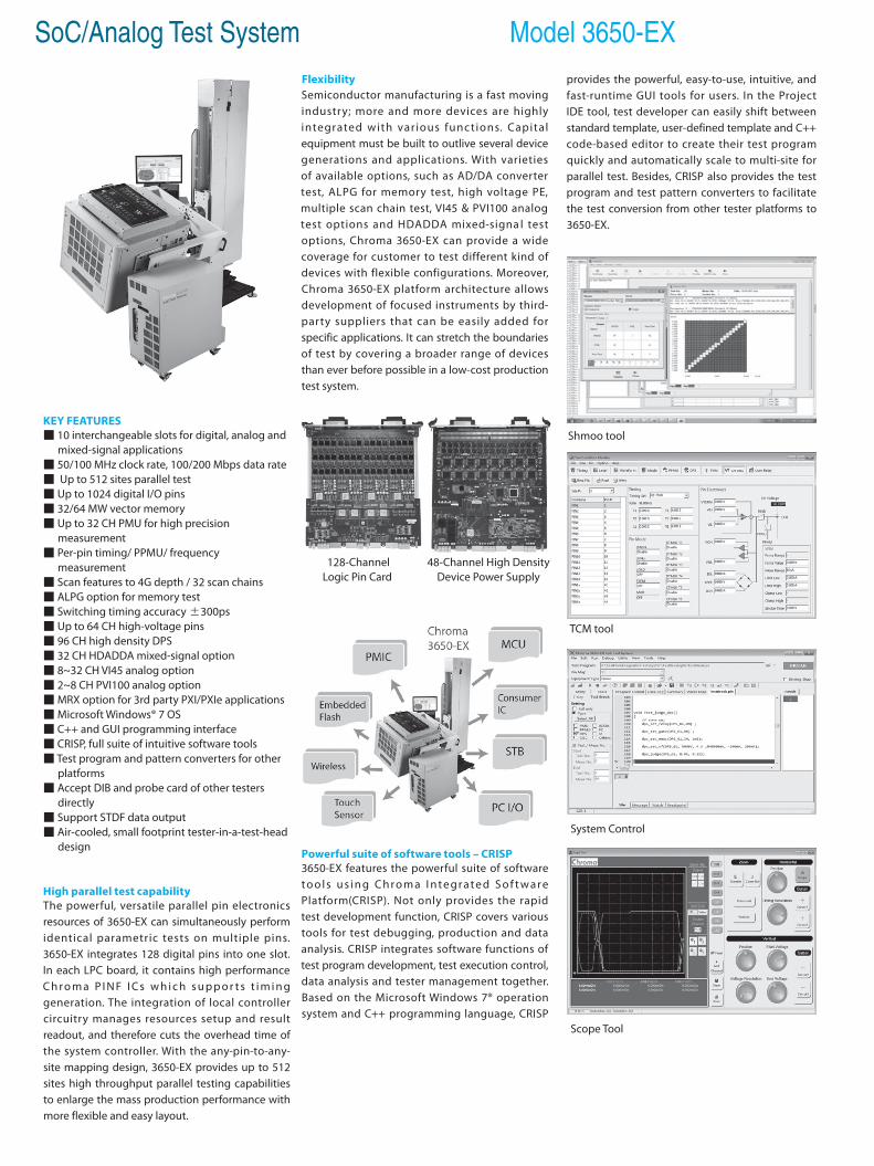
SoC/Analog Test System Model 3650-EX
KEY FEATURES 10 interchangeable slots for digital, analog and mixed-signal applications 50/100 MHz clock rate, 100/200 Mbps data rate Up to 512 sites parallel test Up to 1024 digital I/O pins 32/64 MW vector memory Up to 32 CH PMU for high precision measurement Per-pin timing/ PPMU/ frequency measurement Scan features to 4G depth / 32 scan chains ALPG option for memory test Switching timing accuracy ±300ps Up to 64 CH high-voltage pins 96 CH high density DPS 32 CH HDADDA mixed-signal option 8~32 CH VI45 analog option 2~8 CH PVI100 analog option MRX option for 3rd party PXI/PXIe applications Microsoft Windows® 7 OS C++ and GUI programming interface CRISP, full suite of intuitive software tools Test program and pattern converters for other platforms Accept DIB and probe card of other testers directly Support STDF data output Air-cooled, small footprint tester-in-a-test-head design
High parallel test capabilityThe powerful, versatile parallel pin electronics resources of 3650-EX can simultaneously perform identical parametric tests on multiple pins. 3650-EX integrates 128 digital pins into one slot. In each LPC board, it contains high performance C h r o m a P I N F I C s w h i c h s u p p o r t s t i m i n g generation. The integration of local controller circuitry manages resources setup and result readout, and therefore cuts the overhead time of the system controller. With the any-pin-to-any-site mapping design, 3650-EX provides up to 512 sites high throughput parallel testing capabilities to enlarge the mass production performance with more flexible and easy layout.
FlexibilitySemiconductor manufacturing is a fast moving industry; more and more devices are highly integrated with var ious functions. Capital equipment must be built to outlive several device generations and applications. With varieties of available options, such as AD/DA converter test, ALPG for memory test, high voltage PE, multiple scan chain test, VI45 & PVI100 analog test options and HDADDA mixed-signa l test options, Chroma 3650-EX can provide a wide coverage for customer to test different kind of devices with flexible configurations. Moreover, Chroma 3650-EX platform architecture allows development of focused instruments by third-party suppliers that can be easily added for specific applications. It can stretch the boundaries of test by covering a broader range of devices than ever before possible in a low-cost production test system.
Powerful suite of software tools – CRISP3650-EX features the powerful suite of software t o o l s u s i n g C h ro m a I n t e g r a t e d S o f t w a re Platform(CRISP). Not only provides the rapid test development function, CRISP covers various tools for test debugging, production and data analysis. CRISP integrates software functions of test program development, test execution control, data analysis and tester management together. Based on the Microsoft Windows 7® operation system and C++ programming language, CRISP
128-ChannelLogic Pin Card
48-Channel High Density Device Power Supply
provides the powerful, easy-to-use, intuitive, and fast-runtime GUI tools for users. In the Project IDE tool, test developer can easily shift between standard template, user-defined template and C++ code-based editor to create their test program quickly and automatically scale to multi-site for parallel test. Besides, CRISP also provides the test program and test pattern converters to facilitate the test conversion from other tester platforms to 3650-EX.
System Control
Scope Tool
Shmoo tool
TCM tool
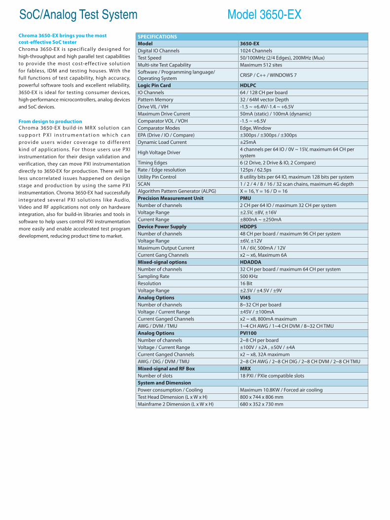
SoC/Analog Test System Model 3650-EXChroma 3650-EX brings you the most cost-effective SoC testerChroma 3650-EX is specifically designed for high-throughput and high parallel test capabilities to provide the most cost-effective solution for fabless, IDM and testing houses. With the full functions of test capability, high accuracy, powerful software tools and excellent reliability, 3650-EX is ideal for testing consumer devices, high-performance microcontrollers, analog devices and SoC devices.
From design to productionChroma 3650-EX build-in MRX solution can s u p p o r t P X I i n s t r u m e n t a t i o n w h i c h c a n provide users wider coverage to di f ferent kind of applications. For those users use PXI instrumentation for their design validation and verification, they can move PXI instrumentation directly to 3650-EX for production. There will be less uncorrelated issues happened on design stage and production by using the same PXI instrumentation. Chroma 3650-EX had successfully integrated several PXI solutions l ike Audio, Video and RF applications not only on hardware integration, also for build-in libraries and tools in software to help users control PXI instrumentation more easily and enable accelerated test program development, reducing product time to market.
SPECIFICATIONSModel 3650-EXDigital IO Channels 1024 ChannelsTest Speed 50/100MHz (2/4 Edges), 200MHz (Mux)Multi-site Test Capability Maximum 512 sitesSoftware / Programming language/ Operating System CRISP / C++ / WINDOWS 7
Logic Pin Card HDLPCIO Channels 64 / 128 CH per boardPattern Memory 32 / 64M vector DepthDrive VIL / VIH -1.5 ~ +6.4V/-1.4 ~ +6.5VMaximum Drive Current 50mA (static) / 100mA (dynamic)Comparator VOL / VOH -1.5 ~ +6.5VComparator Modes Edge, WindowEPA (Drive / IO / Compare) ±300ps / ±300ps / ±300psDynamic Load Current ±25mA
High Voltage Driver 4 channels per 64 IO / 0V ~ 15V, maximum 64 CH per system
Timing Edges 6 (2 Drive, 2 Drive & IO, 2 Compare)Rate / Edge resolution 125ps / 62.5psUtility Pin Control 8 utility bits per 64 IO, maximum 128 bits per systemSCAN 1 / 2 / 4 / 8 / 16 / 32 scan chains, maximum 4G depthAlgorithm Pattern Generator (ALPG) X = 16, Y = 16 / D = 16Precision Measurement Unit PMUNumber of channels 2 CH per 64 IO / maximum 32 CH per systemVoltage Range ±2.5V, ±8V, ±16VCurrent Range ±800nA ~ ±250mADevice Power Supply HDDPSNumber of channels 48 CH per board / maximum 96 CH per systemVoltage Range ±6V, ±12VMaximum Output Current 1A / 6V, 500mA / 12VCurrent Gang Channels x2 ~ x6, Maximum 6AMixed-signal options HDADDANumber of channels 32 CH per board / maximum 64 CH per systemSampling Rate 500 KHzResolution 16 BitVoltage Range ±2.5V / ±4.5V / ±9VAnalog Options VI45Number of channels 8~32 CH per boardVoltage / Current Range ±45V / ±100mACurrent Ganged Channels x2 ~ x8, 800mA maximumAWG / DVM / TMU 1~4 CH AWG / 1~4 CH DVM / 8~32 CH TMUAnalog Options PVI100Number of channels 2~8 CH per boardVoltage / Current Range ±100V / ±2A , ±50V / ±4ACurrent Ganged Channels x2 ~ x8, 32A maximumAWG / DIG / DVM / TMU 2~8 CH AWG / 2~8 CH DIG / 2~8 CH DVM / 2~8 CH TMUMixed-signal and RF Box MRXNumber of slots 18 PXI / PXIe compatible slotsSystem and DimensionPower consumption / Cooling Maximum 10.8KW / Forced air coolingTest Head Dimension (L x W x H) 800 x 744 x 806 mm Mainframe 2 Dimension (L x W x H) 680 x 352 x 730 mm
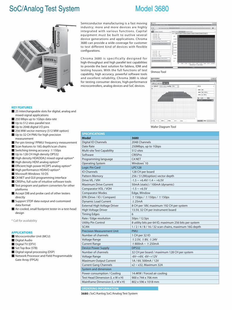
SoC/Analog Test System Model 3680
ORDERING INFORMATION
Shmoo Tool
Wafer Diagram Tool
3680 : SoC/Aanlog SoC/Analog Test System
KEY FEATURES 25 interchangeable slots for digital, analog and mixed-signal applications 250 Mbps up to 1Gbps data rate Up to 512 sites parallel test Up to 2048 digital I/O pins 256 MW vector memory (512 MW option) Up to 32 CH PMU for high precision measurement Per-pin timing/ PPMU/ frequency measurement Scan features to 16G depth/scan chains Switching timing accuracy ±150ps Up to 128 CH High density DPS32 High density HDADDA2 mixed-signal option* High density HDVI analog option* Efficient high power HCDPS analog option* High performance HDAVO option* Microsoft Windows 10 OS C#.NET and GUI programming interface CRISPro, full suite of intuitive software tools Test program and pattern converters for other platforms Accept DIB and probe card of other testers directly Support STDF data output and customized data format Air-cooled, small footprint tester-in-a-test-head design
* Call for availability
APPLICATIONS Microcontroller Unit (MCU) Digital Audio Digital TV (DTV) Set Top Box (STB) Digital signal processing (DSP) Network Processor and Field Programmable Gate Array (FPGA)
SPECIFICATIONSModel 3680Digital IO Channels 2048 ChannelsDate Rate 250Mbps, up to 1GbpsMulti-site Test Capability 512 sitesSoftware CRISProProgramming language C#.NETOperating System Windows® 10Logic Pin Card LPC128IO Channels 128 CH per boardPattern Memory 256 / 512M(option) vector depthDrive VIL / VIH -1.5 ~ +6.4V/-1.4 ~ +6.5VMaximum Drive Current 50mA (static) / 100mA (dynamic)Comparator VOL / VOH -1.5 ~ +6.5VComparator Modes Edge, WindowEPA (Drive / IO / Compare) ±150ps / ±150ps / ±150psDynamic Load Current ±25mAExternal High Voltage Driver 8 CH per 18V, maximum 192 CH per systemHigh Voltage Driver 13.5V, 32 CH per instrument boardTiming Edges 6Rate / Edge resolution 50ps / 12.5psUtility Pin Control 8 utility bits per 64 IO, maximum 256 bits per systemSCAN 1 / 2 / 4 / 8 / 16 / 32 scan chains, maximum 16G depthPrecision Measurement Unit PMUNumber of channels 1 CH per 32 IOVoltage Range ±2.5V, ±8V, ±24VCurrent Range ±800nA ~ ±250mADevice Power Supply DPS32Number of channels 32 CH per board / maximum 128 CH per systemVoltage Range -6V~+6V, -6V~+12VMaximum Output Current 1A / 6V, 500mA / 12VCurrent Gang Channels x2 ~ x32, Maximum 32ASystem and dimensionPower consumption / Cooling 14.4KW / Forced air coolingTest Head Dimension (L x W x H) 900 x 744 x 706 mmMainframe Dimension (L x W x H) 802 x 596 x 1018 mm
Semiconductor manufacturing is a fast moving industry; more and more devices are highly integrated with var ious func t ions. Capita l equipment must be built to outlive several device generations and applications. Chroma 3680 can provide a wide coverage for customer to test different kind of devices with flexible configurations.
C h ro m a 3680 i s s p e c i f i c a l l y d e s i g n e d fo r high-throughput and high parallel test capabilities to provide the best solution for fabless, IDM and testing houses. With the full functions of test capability, high accuracy, powerful software tools and excellent reliability, Chroma 3680 is ideal for testing consumer devices, high-performance microcontrollers, analog devices and SoC devices.
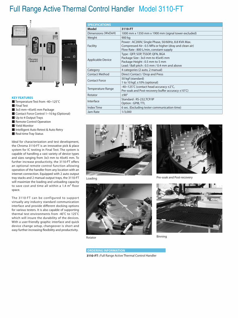
Full Range Active Thermal Control Handler Model 3110-FT
KEY FEATURES Temperature Test from -40~125˚C Final Test 3x3 mm~45x45 mm Package Contact Force Control 1~10 kg (Optional) Up to 4 Output Trays Remote Control Operation Yield Monitor Intelligent Auto Retest & Auto Retry Real-time Tray Status
Ideal for characterization and test development, the Chroma 3110-FT is an innovative pick & place system for IC testing in Final Test. The system is capable of handling a vast variety of device types and sizes ranging from 3x3 mm to 45x45 mm. To further increase productivity, the 3110-FT offers an optional remote control function allowing operation of the handler from any location with an internet connection. Equipped with 2 auto output tray stacks and 2 manual output trays, the 3110-FT will maximize the loading and unloading capacity to save cost and time all within a 1.4 m² floor space.
The 3110-FT can be configured to suppor t virtually any industry standard communication interface and provide different docking options for various testers. It is also capable of supporting thermal test environments from -40˚C to 125˚C which will insure the durability of the devices. With a user-friendly graphic interface and quick device change setup, changeover is short and easy further increasing flexibility and productivity.
ORDERING INFORMATION
3110-FT : Full Range Active Thermal Control Handler
Loading
Binning
Pre-soak and Post-recovery
Rotator
SPECIFICATIONSModel 3110-FTDimensions (WxDxH) 1000 mm x 1350 mm x 1900 mm (signal tower excluded) Weight 900 kg
Facility Power : AC200V, Single Phase, 50/60Hz, 8.8 KVA Max.Compressed Air : 0.5 MPa or higher (dray and clean air)Flow Rate : 800 L/min, constant supply
Applicable Device
Type : QFP, SOP, TSSOP, QFN, BGA Package Size : 3x3 mm to 45x45 mm Package Height : 0.5 mm to 5 mm Lead / Ball pitch : 0.5 mm / 0.4 mm and above
Category 4 categories (2 auto, 2 manual) Contact Method Direct Contact / Drop and Press
Contact Force 50 kgf (standard)1 to 10 kgf, ±10% (optional)
Temperature Range -40~125˚C (contact head accuracy ±2˚C, Pre-soak and Post-recovery buffer accuracy ±10˚C)
Rotator ±90°
Interface Standard : RS-232,TCP/IPOption : GPIB, TTL
Index Time 6 sec. (Excluding tester communication time)Jam Rate 1/3,000
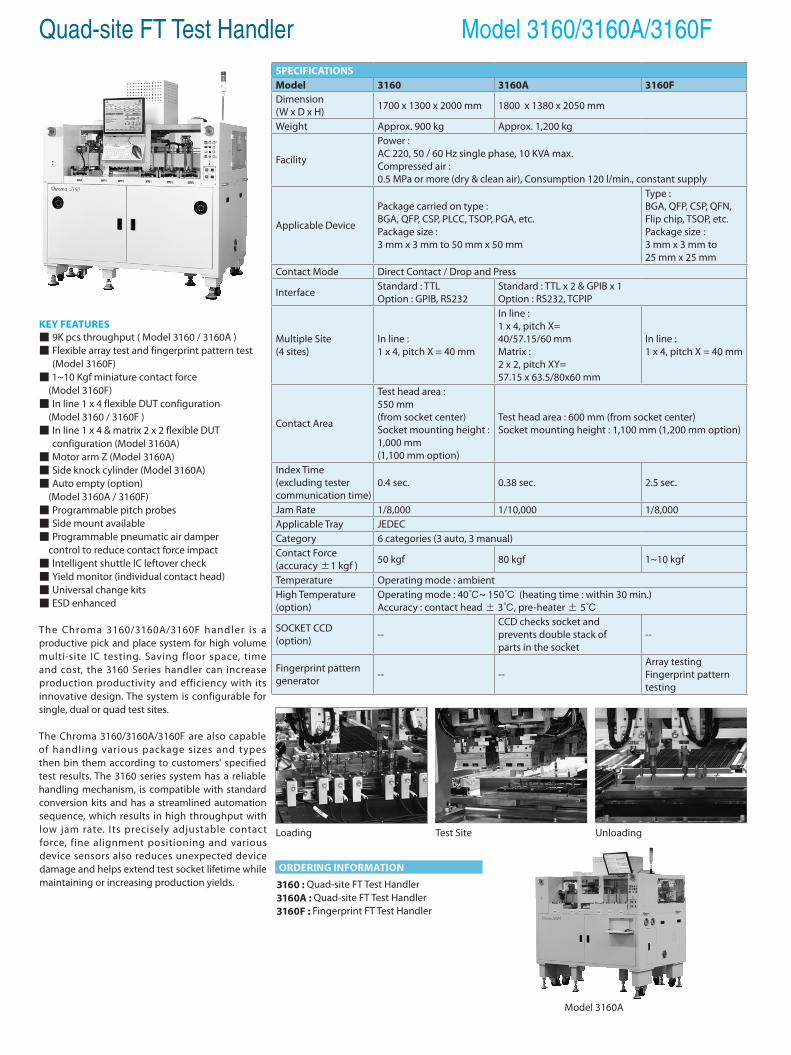
Quad-site FT Test Handler Model 3160/3160A/3160F
KEY FEATURES 9K pcs throughput ( Model 3160 / 3160A ) Flexible array test and fingerprint pattern test
(Model 3160F) 1~10 Kgf miniature contact force (Model 3160F) In line 1 x 4 flexible DUT configuration (Model 3160 / 3160F ) In line 1 x 4 & matrix 2 x 2 flexible DUT
configuration (Model 3160A) Motor arm Z (Model 3160A) Side knock cylinder (Model 3160A) Auto empty (option) (Model 3160A / 3160F) Programmable pitch probes Side mount available Programmable pneumatic air damper control to reduce contact force impact Intelligent shuttle IC leftover check Yield monitor (individual contact head) Universal change kits ESD enhanced
The Chroma 3160/3160A/3160F handler is a productive pick and place system for high volume multi-site IC testing. Saving floor space, time and cost, the 3160 Series handler can increase production productivity and efficiency with its innovative design. The system is configurable for single, dual or quad test sites.
The Chroma 3160/3160A/3160F are also capable of handling various package sizes and types then bin them according to customers' specified test results. The 3160 series system has a reliable handling mechanism, is compatible with standard conversion kits and has a streamlined automation sequence, which results in high throughput with low jam rate. Its precisely adjustable contact force, fine alignment positioning and various device sensors also reduces unexpected device damage and helps extend test socket lifetime while maintaining or increasing production yields.
ORDERING INFORMATION
3160 : Quad-site FT Test Handler3160A : Quad-site FT Test Handler3160F : Fingerprint FT Test Handler
Model 3160A
SPECIFICATIONSModel 3160 3160A 3160FDimension(W x D x H) 1700 x 1300 x 2000 mm 1800 x 1380 x 2050 mm
Weight Approx. 900 kg Approx. 1,200 kg
Facility
Power : AC 220, 50 / 60 Hz single phase, 10 KVA max.Compressed air : 0.5 MPa or more (dry & clean air), Consumption 120 l/min., constant supply
Applicable Device
Package carried on type : BGA, QFP, CSP, PLCC, TSOP, PGA, etc.Package size : 3 mm x 3 mm to 50 mm x 50 mm
Type : BGA, QFP, CSP, QFN, Flip chip, TSOP, etc.Package size : 3 mm x 3 mm to 25 mm x 25 mm
Contact Mode Direct Contact / Drop and Press
Interface Standard : TTLOption : GPIB, RS232
Standard : TTL x 2 & GPIB x 1Option : RS232, TCPIP
Multiple Site(4 sites)
In line : 1 x 4, pitch X = 40 mm
In line : 1 x 4, pitch X=40/57.15/60 mm Matrix : 2 x 2, pitch XY=57.15 x 63.5/80x60 mm
In line : 1 x 4, pitch X = 40 mm
Contact Area
Test head area : 550 mm(from socket center)Socket mounting height : 1,000 mm (1,100 mm option)
Test head area : 600 mm (from socket center)Socket mounting height : 1,100 mm (1,200 mm option)
Index Time (excluding tester communication time)
0.4 sec. 0.38 sec. 2.5 sec.
Jam Rate 1/8,000 1/10,000 1/8,000Applicable Tray JEDECCategory 6 categories (3 auto, 3 manual)Contact Force(accuracy ±1 kgf ) 50 kgf 80 kgf 1~10 kgf
Temperature Operating mode : ambientHigh Temperature (option)
Operating mode : 40~ 150 (heating time : within 30 min.)Accuracy : contact head ± 3, pre-heater ± 5
SOCKET CCD(option) --
CCD checks socket andprevents double stack of parts in the socket
--
Fingerprint pattern generator -- --
Array testingFingerprint pattern testing
Loading UnloadingTest Site
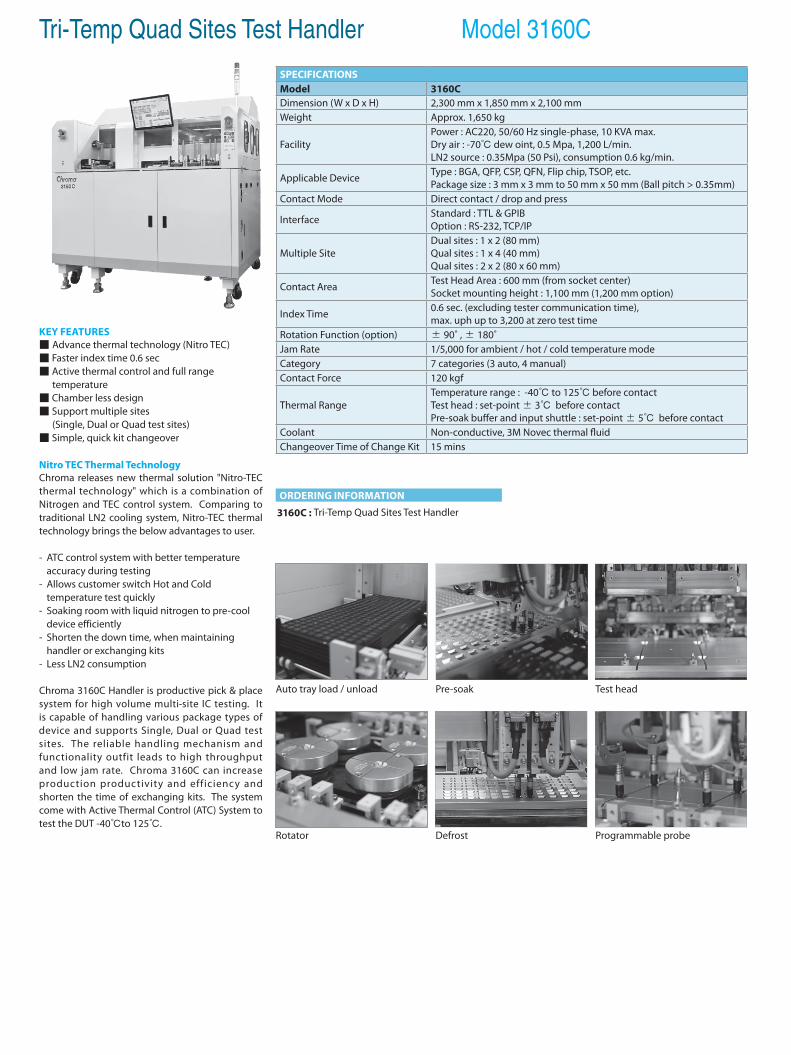
Tri-Temp Quad Sites Test Handler Model 3160C
KEY FEATURES Advance thermal technology (Nitro TEC) Faster index time 0.6 sec Active thermal control and full range temperature Chamber less design Support multiple sites (Single, Dual or Quad test sites) Simple, quick kit changeover
Nitro TEC Thermal TechnologyChroma releases new thermal solution "Nitro-TEC thermal technology" which is a combination of Nitrogen and TEC control system. Comparing to traditional LN2 cooling system, Nitro-TEC thermal technology brings the below advantages to user.
- ATC control system with better temperature accuracy during testing- Allows customer switch Hot and Cold temperature test quickly- Soaking room with liquid nitrogen to pre-cool device efficiently- Shorten the down time, when maintaining handler or exchanging kits- Less LN2 consumption
Chroma 3160C Handler is productive pick & place system for high volume multi-site IC testing. It is capable of handling various package types of device and supports Single, Dual or Quad test sites. The reliable handling mechanism and functionality outfit leads to high throughput and low jam rate. Chroma 3160C can increase production productivity and efficiency and shorten the time of exchanging kits. The system come with Active Thermal Control (ATC) System to test the DUT -40to 125.
SPECIFICATIONSModel 3160CDimension (W x D x H) 2,300 mm x 1,850 mm x 2,100 mm Weight Approx. 1,650 kg
FacilityPower : AC220, 50/60 Hz single-phase, 10 KVA max.Dry air : -70 dew oint, 0.5 Mpa, 1,200 L/min.LN2 source : 0.35Mpa (50 Psi), consumption 0.6 kg/min.
Applicable Device Type : BGA, QFP, CSP, QFN, Flip chip, TSOP, etc.Package size : 3 mm x 3 mm to 50 mm x 50 mm (Ball pitch > 0.35mm)
Contact Mode Direct contact / drop and press
Interface Standard : TTL & GPIBOption : RS-232, TCP/IP
Multiple SiteDual sites : 1 x 2 (80 mm)Qual sites : 1 x 4 (40 mm)Qual sites : 2 x 2 (80 x 60 mm)
Contact Area Test Head Area : 600 mm (from socket center) Socket mounting height : 1,100 mm (1,200 mm option)
Index Time 0.6 sec. (excluding tester communication time), max. uph up to 3,200 at zero test time
Rotation Function (option) ± 90˚ , ± 180˚Jam Rate 1/5,000 for ambient / hot / cold temperature modeCategory 7 categories (3 auto, 4 manual)Contact Force 120 kgf
Thermal RangeTemperature range : -40 to 125 before contactTest head : set-point ± 3 before contact Pre-soak buffer and input shuttle : set-point ± 5 before contact
Coolant Non-conductive, 3M Novec thermal fluidChangeover Time of Change Kit 15 mins
Rotator
Auto tray load / unload
Programmable probe
Test head
Defrost
Pre-soak
ORDERING INFORMATION
3160C : Tri-Temp Quad Sites Test Handler
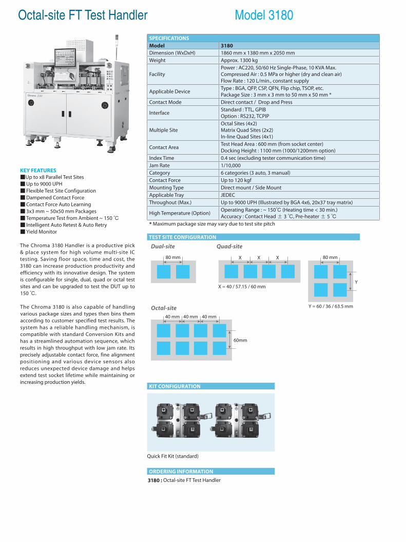
Octal-site FT Test Handler Model 3180
KEY FEATURESUp to x8 Parallel Test Sites Up to 9000 UPH Flexible Test Site Configuration Dampened Contact Force Contact Force Auto Learning 3x3 mm ~ 50x50 mm Packages Temperature Test from Ambient ~ 150 Intelligent Auto Retest & Auto Retry Yield Monitor
The Chroma 3180 Handler is a productive pick & place system for high volume multi-site IC testing. Saving floor space, time and cost, the 3180 can increase production productivity and efficiency with its innovative design. The system is configurable for single, dual, quad or octal test sites and can be upgraded to test the DUT up to 150 .
The Chroma 3180 is also capable of handling various package sizes and types then bins them according to customer specified test results. The system has a reliable handling mechanism, is compatible with standard Conversion Kits and has a streamlined automation sequence, which results in high throughput with low jam rate. Its precisely adjustable contact force, fine alignment positioning and various device sensors also reduces unexpected device damage and helps extend test socket lifetime while maintaining or increasing production yields.
ORDERING INFORMATION
TEST SITE CONFIGURATION
KIT CONFIGURATION
3180 : Octal-site FT Test Handler
SPECIFICATIONSModel 3180Dimension (WxDxH) 1860 mm x 1380 mm x 2050 mmWeight Approx. 1300 kg
FacilityPower : AC220, 50/60 Hz Single-Phase, 10 KVA Max.Compressed Air : 0.5 MPa or higher (dry and clean air)Flow Rate : 120 L/min., constant supply
Applicable Device Type : BGA, QFP, CSP, QFN, Flip chip, TSOP, etc.Package Size : 3 mm x 3 mm to 50 mm x 50 mm *
Contact Mode Direct contact / Drop and Press
Interface Standard : TTL, GPIBOption : RS232, TCPIP
Multiple SiteOctal Sites (4x2)Matrix Quad Sites (2x2) In-line Quad Sites (4x1)
Contact Area Test Head Area : 600 mm (from socket center) Docking Height : 1100 mm (1000/1200mm option)
Index Time 0.4 sec (excluding tester communication time)Jam Rate 1/10,000Category 6 categories (3 auto, 3 manual) Contact Force Up to 120 kgf Mounting Type Direct mount / Side MountApplicable Tray JEDEC Throughout (Max.) Up to 9000 UPH (Illustrated by BGA 4x6, 20x37 tray matrix)
High Temperature (Option) Operating Range : ~ 150 (Heating time < 30 min.)Accuracy : Contact Head ± 3 , Pre-heater ± 5
* Maximum package size may vary due to test site pitch
80 mm
Dual-site Quad-site
Octal-site
X = 40 / 57.15 / 60 mm
Y = 60 / 36 / 63.5 mm
X X X
Y
80 mm
40 mm 40 mm 40 mm
60mm
Quick Fit Kit (standard)
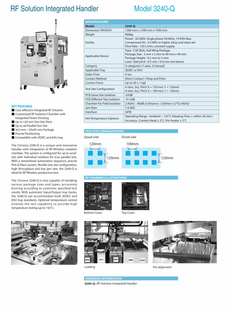
RF Solution Integrated Handler Model 3240-Q
KEY FEATURES Cost-effective Integrated RF Solution Customized RF Isolation Chamber with Integrated Tester Docking Up to 120 mm Test Site Pitch Up to x8 Parallel Test Site 3x3 mm ~ 45x45 mm Package Precise Positioning Compatible with JEDEC and EIAJ tray
The Chroma 3240-Q is a unique and innovative handler with integration of RF/Wireless isolation chamber. The system is configured for up to octal-site with individual isolation for true parallel test. With a streamlined automation sequence, precise Pick & Place system, flexible test site configuration, high throughput and low jam rate, the 3240-Q is ideal for RF/Wireless production test.
The Chroma 3240-Q is also capable of handling various package sizes and types, accurately binning according to customer specified test results. With automatic Input/Output tray stacks, the 3240-Q can accommodate both JEDEC and EIAJ tray standards. Optional temperature control extends the test capability to provide high temperature testing up to 150.
ORDERING INFORMATION
TEST SITE CONFIGURATION
RF CHAMBER ILLUSTRATIONS
3240-Q : RF Solution Integrated Handler
Loading Pre-alignment
SPECIFICATIONSModel 3240-QDimension (WxDxH) 1360 mm x 1390 mm x 1930 mmWeight 900kg
FacilityPower : AC200V, Single phase 50/60Hz, 10 KVA Max.Compressed Air : 0.5 MPa or higher (dray and clean air)Flow Rate : 150 L/min, constant supply
Applicable Device
Type : CSP, BGA, Gull Wing PackagePackage Size : 3 mm x 3 mm to 40 mm x 40 mm Package Height : 0.5 mm to 5 mm Lead / Ball pitch : 0.5 mm / 0.4 mm and above
Category 3 categories (1 auto, 2 manual) Applicable Tray JEDEC or EIAJIndex Time 4 sec.Contact Method Direct Contact / Drop and PressContact Force Up to 50 ± 1 kgf
Test Site Configuration 4 sites, 2x2, Pitch X = 120 mm, Y = 120mm8 sites, 4x2, Pitch X = 100 mm, Y = 120mm
PCB Same Site Isolation -63dBPCB Different Site Isolation -91.5dBChamber Far Field Isolation 2.4GHz : -80dB @ Distance >250mm (=2*λ2.4GHz)Jam Rate 1/5,000 Interface GPIB
Hot Temperature (Option)Operating Range : Ambient ~ 125˚C (Heating Time < within 30 min.)Accuracy : Contact Head ± 3˚C, Pre-heater ± 5˚C
Bottom Cover Top Cover
Quad-site Octal-site
120mm
120mm
100mm
120mm
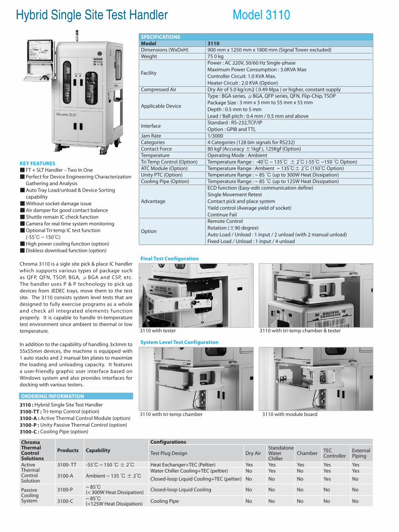
Hybrid Single Site Test Handler Model 3110
KEY FEATURES FT + SLT Handler – Two In One Perfect for Device Engineering Characterization
Gathering and Analysis Auto Tray Load/unload & Device Sorting
capability Without socket damage issue Air damper for good contact balance Shuttle remain IC check function Camera for real time system monitoring Optional Tri-temp IC test function (-55 ~ 150) High power cooling function (option) Diskless download function (option)
Chroma 3110 is a sigle site pick & place IC handler which supports various types of package such as QFP, QFN, TSOP, BGA, μBGA and CSP, etc. The handler uses P & P technology to pick up devices from JEDEC trays, move them to the test site. The 3110 consists system level tests that are designed to fully exercise programs as a whole and check all integrated elements function properly. It is capable to handle tri-temperature test environment since ambient to thermal or low temperature.
In addition to the capability of handling 3x3mm to 55x55mm devices, the machine is equipped with 1 auto stacks and 2 manual bin plates to maximize the loading and unloading capacity. It features a user-friendly graphic user interface based on Windows system and also provides interfaces for docking with various testers.
Final Test Configuration
3110 with tester 3110 with tri-temp chamber & tester
SPECIFICATIONSModel 3110Dimensions (WxDxH) 900 mm x 1250 mm x 1800 mm (Signal Tower excluded)Weight 75 0 kg
Facility
Power : AC 220V, 50/60 Hz Single-phaseMaximum Power Consumption : 3.0KVA MaxController Circuit: 1.0 KVA Max.Heater Circuit : 2.0 KVA (Option)
Compressed Air Dry Air of 5.0 kg/cm2 ( 0.49 Mpa ) or higher, constant supply
Applicable Device
Type : BGA series, μBGA, QFP series, QFN, Flip-Chip, TSOPPackage Size : 3 mm x 3 mm to 55 mm x 55 mmDepth : 0.5 mm to 5 mmLead / Ball pitch : 0.4 mm / 0.5 mm and above
Interface Standard : RS-232,TCP/IPOption : GPIB and TTL
Jam Rate 1/3000 Categories 4 Categories (128 bin signals for RS232)Contact Force 80 kgf (Accuracy ±1kgf ), 125Kgf (Option)Temperature Operating Mode : AmbientTri Temp Control (Option) Temperature Range : -40 ~ 135 ± 2 (-55 ~150 Option)ATC Module (Option) Temperature Range : Ambient ~ 135± 2 (150 Option)Unity PTC (Option) Temperature Range : ~ 85 (up to 300W Heat Dissipation)Cooling Pipe (Option) Temperature Range : ~ 85 (up to 125W Heat Dissipation)
Advantage
ECD function (Easy-edit communication define)Single Movement RetestContact pick and place systemYield control (Average yield of socket)Continue Fail
Option
Remote ControlRotation (±90 degree)Auto Load / Unload : 1 input / 2 unload (with 2 manual unload)Fixed Load / Unload : 1 input / 4 unload
3110 with tri-temp chamber 3110 with module board
System Level Test Configuration
ORDERING INFORMATION
3110 : Hybrid Single Site Test Handler3100-TT : Tri-temp Control (option)3100-A : Active Thermal Control Module (option)3100-P : Unity Passive Thermal Control (option)3100-C : Cooling Pipe (option)
Chroma ThermalControlSolutions
Products Capability
Configurations
Test Plug Design Dry AirStandalone Water Chiller
Chamber TEC Controller
External Piping
Active Thermal Control Solution
3100- TT -55 ~ 150 ± 2 Heat Exchanger+TEC (Peltier) Yes Yes Yes Yes Yes
3100-A Ambient ~ 135 ± 2Water Chiller Cooling+TEC (peltier) No Yes No Yes YesClosed-loop Liquid Cooling+TEC (peltier) No No No Yes No
Passive Cooling System
3100-P ~ 85(< 300W Heat Dissipation) Closed-loop Liquid Cooling No No No No No
3100-C ~ 85(<125W Heat Dissipation) Cooling Pipe No No No No No
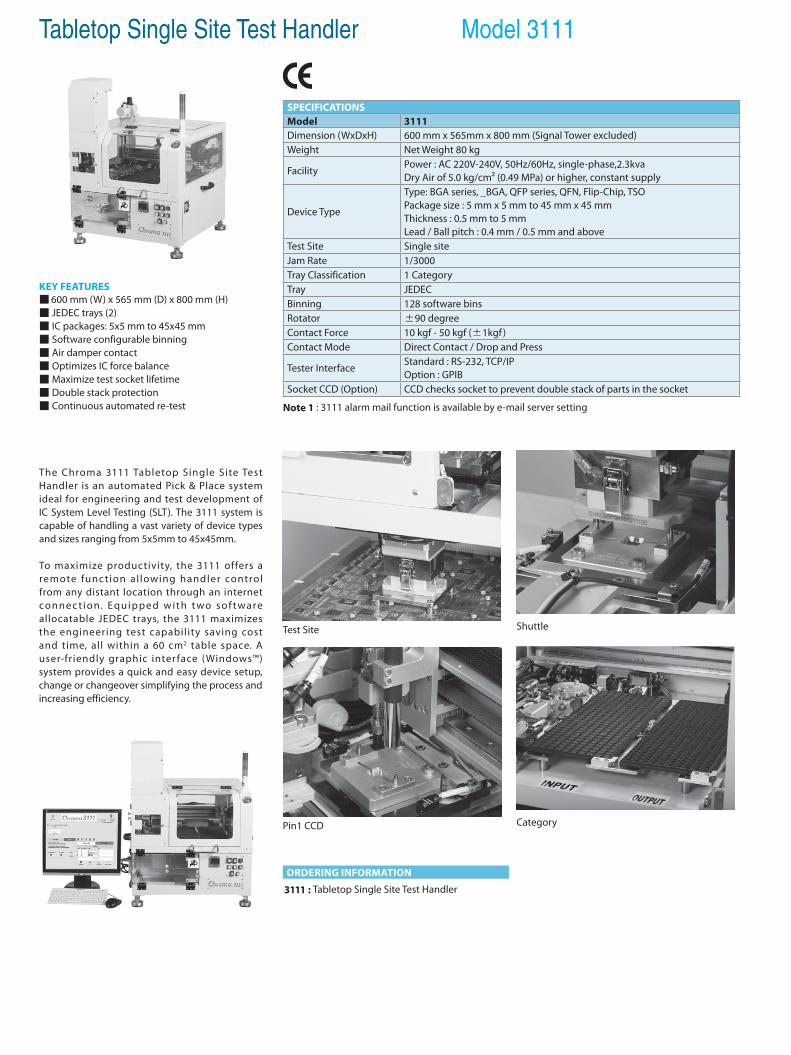
Tabletop Single Site Test Handler Model 3111
KEY FEATURES 600 mm (W) x 565 mm (D) x 800 mm (H) JEDEC trays (2) IC packages: 5x5 mm to 45x45 mm Software configurable binning Air damper contact Optimizes IC force balance Maximize test socket lifetime Double stack protection Continuous automated re-test
The Chroma 3111 Tabletop Single Site Test Handler is an automated Pick & Place system ideal for engineering and test development of IC System Level Testing (SLT). The 3111 system is capable of handling a vast variety of device types and sizes ranging from 5x5mm to 45x45mm.
To maximize productivity, the 3111 offers a remote func tion al lowing handler control from any distant location through an internet co n n e c t i o n. Eq u i p p e d w i t h t wo s o f t wa re allocatable JEDEC trays, the 3111 maximizes the engineering test capability saving cost and time, all within a 60 cm2 table space. A user-friendly graphic inter face (Windows™) system provides a quick and easy device setup, change or changeover simplifying the process and increasing efficiency.
ORDERING INFORMATION
3111 : Tabletop Single Site Test Handler
Test Site
Category
Shuttle
Pin1 CCD
SPECIFICATIONSModel 3111Dimension (WxDxH) 600 mm x 565mm x 800 mm (Signal Tower excluded)Weight Net Weight 80 kg
FacilityPower : AC 220V-240V, 50Hz/60Hz, single-phase,2.3kva Dry Air of 5.0 kg/cm² (0.49 MPa) or higher, constant supply
Device Type
Type: BGA series, _BGA, QFP series, QFN, Flip-Chip, TSOPackage size : 5 mm x 5 mm to 45 mm x 45 mmThickness : 0.5 mm to 5 mmLead / Ball pitch : 0.4 mm / 0.5 mm and above
Test Site Single siteJam Rate 1/3000Tray Classification 1 CategoryTray JEDECBinning 128 software binsRotator ±90 degreeContact Force 10 kgf - 50 kgf (±1kgf)Contact Mode Direct Contact / Drop and Press
Tester InterfaceStandard : RS-232, TCP/IPOption : GPIB
Socket CCD (Option) CCD checks socket to prevent double stack of parts in the socket
Note 1 : 3111 alarm mail function is available by e-mail server setting
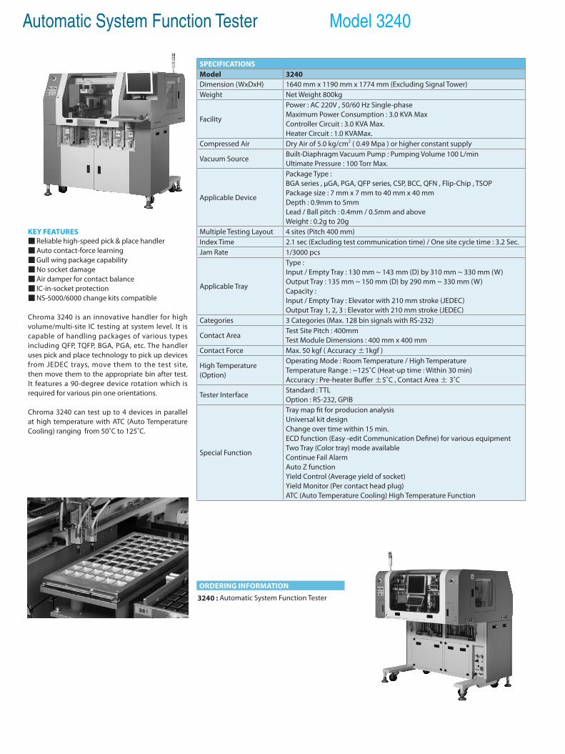
Automatic System Function Tester Model 3240
KEY FEATURES Reliable high-speed pick & place handler Auto contact-force learning Gull wing package capability No socket damage Air damper for contact balance IC-in-socket protection NS-5000/6000 change kits compatible
Chroma 3240 is an innovative handler for high volume/multi-site IC testing at system level. It is capable of handling packages of various types including QFP, TQFP, BGA, PGA, etc. The handler uses pick and place technology to pick up devices from JEDEC trays, move them to the test site, then move them to the appropriate bin after test. It features a 90-degree device rotation which is required for various pin one orientations.
Chroma 3240 can test up to 4 devices in parallel at high temperature with ATC (Auto Temperature Cooling) ranging from 50˚C to 125˚C.
SPECIFICATIONSModel 3240Dimension (WxDxH) 1640 mm x 1190 mm x 1774 mm (Excluding Signal Tower)Weight Net Weight 800kg
Facility
Power : AC 220V , 50/60 Hz Single-phaseMaximum Power Consumption : 3.0 KVA MaxController Circuit : 3.0 KVA Max.Heater Circuit : 1.0 KVAMax.
Compressed Air Dry Air of 5.0 kg/cm2 ( 0.49 Mpa ) or higher constant supply
Vacuum SourceBuilt-Diaphragm Vacuum Pump : Pumping Volume 100 L/minUltimate Pressure : 100 Torr Max.
Applicable Device
Package Type : BGA series , µGA, PGA, QFP series, CSP, BCC, QFN , Flip-Chip , TSOPPackage size : 7 mm x 7 mm to 40 mm x 40 mmDepth : 0.9mm to 5mmLead / Ball pitch : 0.4mm / 0.5mm and aboveWeight : 0.2g to 20g
Multiple Testing Layout 4 sites (Pitch 400 mm)Index Time 2.1 sec (Excluding test communication time) / One site cycle time : 3.2 Sec.Jam Rate 1/3000 pcs
Applicable Tray
Type : Input / Empty Tray : 130 mm ~ 143 mm (D) by 310 mm ~ 330 mm (W)Output Tray : 135 mm ~ 150 mm (D) by 290 mm ~ 330 mm (W)Capacity : Input / Empty Tray : Elevator with 210 mm stroke (JEDEC)Output Tray 1, 2, 3 : Elevator with 210 mm stroke (JEDEC)
Categories 3 Categories (Max. 128 bin signals with RS-232)
Contact AreaTest Site Pitch : 400mmTest Module Dimensions : 400 mm x 400 mm
Contact Force Max. 50 kgf ( Accuracy ±1kgf )
High Temperature (Option)
Operating Mode : Room Temperature / High TemperatureTemperature Range : ~125˚C (Heat-up time : Within 30 min)Accuracy : Pre-heater Buffer ±5˚C , Contact Area ± 3˚C
Tester InterfaceStandard : TTLOption : RS-232, GPIB
Special Function
Tray map fit for producion analysisUniversal kit designChange over time within 15 min.ECD function (Easy -edit Communication Define) for various equipmentTwo Tray (Color tray) mode availableContinue Fail AlarmAuto Z functionYield Control (Average yield of socket)Yield Monitor (Per contact head plug)ATC (Auto Temperature Cooling) High Temperature Function
ORDERING INFORMATION
3240 : Automatic System Function Tester
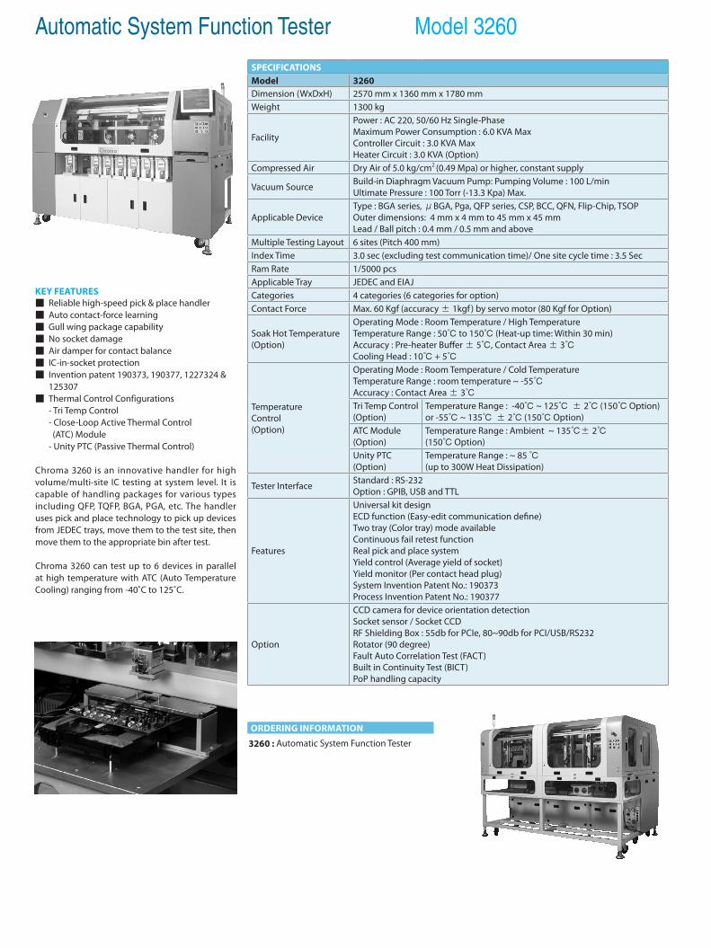
Automatic System Function Tester Model 3260
KEY FEATURES Reliable high-speed pick & place handler Auto contact-force learning Gull wing package capability No socket damage Air damper for contact balance IC-in-socket protection Invention patent 190373, 190377, 1227324 & 125307 Thermal Control Configurations - Tri Temp Control - Close-Loop Active Thermal Control (ATC) Module - Unity PTC (Passive Thermal Control)
Chroma 3260 is an innovative handler for high volume/multi-site IC testing at system level. It is capable of handling packages for various types including QFP, TQFP, BGA, PGA, etc. The handler uses pick and place technology to pick up devices from JEDEC trays, move them to the test site, then move them to the appropriate bin after test.
Chroma 3260 can test up to 6 devices in parallel at high temperature with ATC (Auto Temperature Cooling) ranging from -40˚C to 125˚C.
ORDERING INFORMATION
3260 : Automatic System Function Tester
SPECIFICATIONSModel 3260Dimension (WxDxH) 2570 mm x 1360 mm x 1780 mmWeight 1300 kg
Facility
Power : AC 220, 50/60 Hz Single-PhaseMaximum Power Consumption : 6.0 KVA MaxController Circuit : 3.0 KVA MaxHeater Circuit : 3.0 KVA (Option)
Compressed Air Dry Air of 5.0 kg/cm2 (0.49 Mpa) or higher, constant supply
Vacuum Source Build-in Diaphragm Vacuum Pump: Pumping Volume : 100 L/minUltimate Pressure : 100 Torr (-13.3 Kpa) Max.
Applicable DeviceType : BGA series, μBGA, Pga, QFP series, CSP, BCC, QFN, Flip-Chip, TSOPOuter dimensions: 4 mm x 4 mm to 45 mm x 45 mmLead / Ball pitch : 0.4 mm / 0.5 mm and above
Multiple Testing Layout 6 sites (Pitch 400 mm)Index Time 3.0 sec (excluding test communication time)/ One site cycle time : 3.5 SecRam Rate 1/5000 pcsApplicable Tray JEDEC and EIAJCategories 4 categories (6 categories for option)Contact Force Max. 60 Kgf (accuracy ± 1kgf ) by servo motor (80 Kgf for Option)
Soak Hot Temperature(Option)
Operating Mode : Room Temperature / High TemperatureTemperature Range : 50 to 150 (Heat-up time: Within 30 min)Accuracy : Pre-heater Buffer ± 5, Contact Area ± 3Cooling Head : 10 + 5
TemperatureControl(Option)
Operating Mode : Room Temperature / Cold TemperatureTemperature Range : room temperature ~ -55Accuracy : Contact Area ± 3Tri Temp Control(Option)
Temperature Range : -40 ~ 125 ± 2 (150 Option) or -55 ~ 135 ± 2 (150 Option)
ATC Module (Option)
Temperature Range : Ambient ~ 135± 2 (150 Option)
Unity PTC (Option)
Temperature Range : ~ 85 (up to 300W Heat Dissipation)
Tester Interface Standard : RS-232Option : GPIB, USB and TTL
Features
Universal kit designECD function (Easy-edit communication define)Two tray (Color tray) mode availableContinuous fail retest functionReal pick and place systemYield control (Average yield of socket)Yield monitor (Per contact head plug)System Invention Patent No.: 190373Process Invention Patent No.: 190377
Option
CCD camera for device orientation detectionSocket sensor / Socket CCDRF Shielding Box : 55db for PCIe, 80~90db for PCI/USB/RS232Rotator (90 degree)Fault Auto Correlation Test (FACT)Built in Continuity Test (BICT)PoP handling capacity
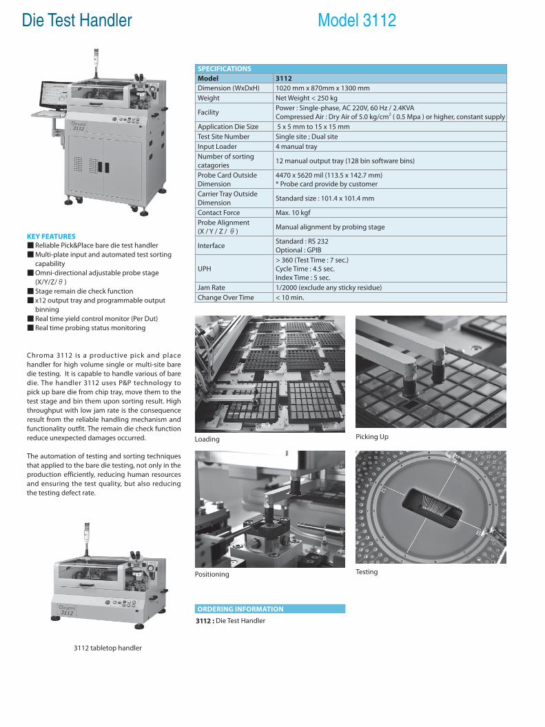
Die Test Handler Model 3112
KEY FEATURES Reliable Pick&Place bare die test handler Multi-plate input and automated test sorting
capability Omni-directional adjustable probe stage (X/Y/Z/θ) Stage remain die check function x12 output tray and programmable output
binning Real time yield control monitor (Per Dut) Real time probing status monitoring
Chroma 3112 is a productive pick and place handler for high volume single or multi-site bare die testing. It is capable to handle various of bare die. The handler 3112 uses P&P technology to pick up bare die from chip tray, move them to the test stage and bin them upon sorting result. High throughput with low jam rate is the consequence result from the reliable handling mechanism and functionality outfit. The remain die check function reduce unexpected damages occurred.
The automation of testing and sorting techniques that applied to the bare die testing, not only in the production efficiently, reducing human resources and ensuring the test quality, but also reducing the testing defect rate.
ORDERING INFORMATION
3112 : Die Test Handler
3112 tabletop handler
Loading
Testing
Picking Up
Positioning
SPECIFICATIONSModel 3112Dimension (WxDxH) 1020 mm x 870mm x 1300 mmWeight Net Weight < 250 kg
Facility Power : Single-phase, AC 220V, 60 Hz / 2.4KVACompressed Air : Dry Air of 5.0 kg/cm2 ( 0.5 Mpa ) or higher, constant supply
Application Die Size 5 x 5 mm to 15 x 15 mmTest Site Number Single site ; Dual siteInput Loader 4 manual trayNumber of sortingcatagories 12 manual output tray (128 bin software bins)
Probe Card OutsideDimension
4470 x 5620 mil (113.5 x 142.7 mm) * Probe card provide by customer
Carrier Tray OutsideDimension Standard size : 101.4 x 101.4 mm
Contact Force Max. 10 kgfProbe Alignment(X / Y / Z / θ) Manual alignment by probing stage
Interface Standard : RS 232Optional : GPIB
UPH> 360 (Test Time : 7 sec.) Cycle Time : 4.5 sec.Index Time : 5 sec.
Jam Rate 1/2000 (exclude any sticky residue)Change Over Time < 10 min.
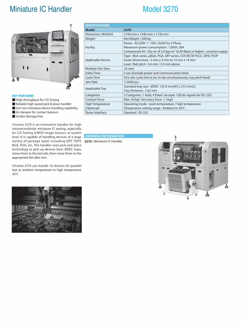
Miniature IC Handler Model 3270
KEY FEATURES High throughput for CIS Testing Reliable high-speed pick & place handler 3x3 mm miniature device handling capability Air damper for contact balance Socket damage free
Chroma 3270 is an innovative handler for high volume/multisite miniature IC testing, especially for CIS Testing (CMOS Image Sensor), at system level. It is capable of handling devices of a large variety of package types including QFP, TQFP, BGA, PGA, etc. The handler uses pick and place technology to pick up devices from JEDEC trays, move them to the test site, then move them to the appropriate bin after test.
Chroma 3270 can handle 16 devices for parallel test at ambient temperature to high temperature 50˚C
SPECIFICATIONSModel 3270Dimension (WxDxH) 2100 mm x 1540 mm x 1720 mmWeight Net Weight 1300 kg
FacilityPower : AC220V ± 10%, 50/60 Hz 3-PhaseMaximum power consumption : 12KVA, 20A Compressed Air : Dry air of 5.0 kg/cm2 (0.49 Mpa) or higher, constant supply
Applicable DeviceType : BGA series, µBGA, PGA, QFP series, CSP, WCSP, PLCC, QFN, TSOPOuter dimensions : 3 mm x 3 mm to 14 mm x 14 mm Lead / Ball pitch : 0.4 mm / 0.5 mm above
Multiple Test Sites 16 sitesIndex Time 5 sec (Exclude power and communication time)Cycle Time One site cycle time 6 sec (4 site simultaneously, tray pitch fixed)Jam Rate 1/2000 pcs
Applicable TrayStandard tray size : JEDEC 135.9 mm(W) x 315 mm(L)Tray thickness : 7.62 mm
Categories 5 Categories, 1 Auto, 4 Fixed (accepts 128 bin signals for RS-232) Contact Force Max. 50 kgf (Accuracy force ±1kgf)High Temperature (Optional)
Operating mode : room temperature / high temperatureTemperature setting range : Ambient to 50˚C
Tester Interface Standard : RS-232
ORDERING INFORMATION
3270 : Miniature IC Handler
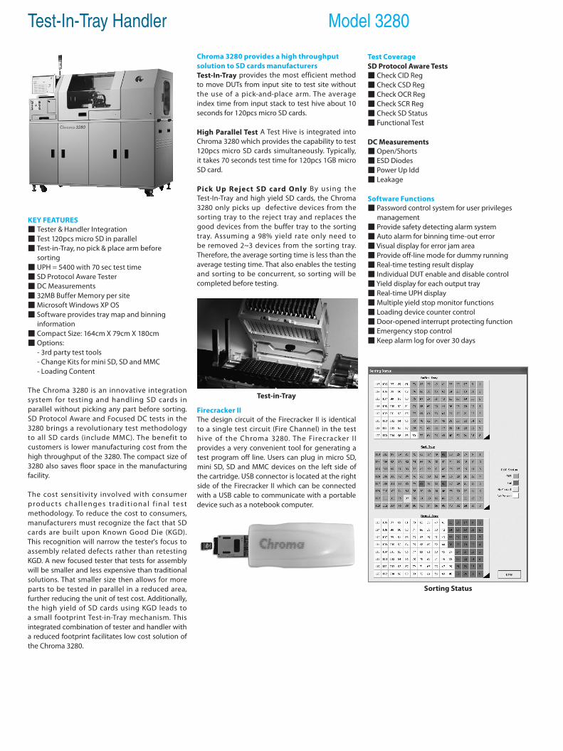
Test-In-Tray Handler Model 3280
KEY FEATURES Tester & Handler Integration Test 120pcs micro SD in parallel Test-in-Tray, no pick & place arm before sorting UPH = 5400 with 70 sec test time SD Protocol Aware Tester DC Measurements 32MB Buffer Memory per site Microsoft Windows XP OS Software provides tray map and binning information Compact Size: 164cm X 79cm X 180cm Options: - 3rd party test tools - Change Kits for mini SD, SD and MMC - Loading Content
The Chroma 3280 is an innovative integration system for testing and handling SD cards in parallel without picking any part before sorting. SD Protocol Aware and Focused DC tests in the 3280 brings a revolutionary test methodology to all SD cards (include MMC). The benefit to customers is lower manufacturing cost from the high throughput of the 3280. The compact size of 3280 also saves floor space in the manufacturing facility.
The cost sensitivity involved with consumer produc ts chal lenges t radit ional f inal test methodology. To reduce the cost to consumers, manufacturers must recognize the fact that SD cards are built upon Known Good Die (KGD). This recognition will narrow the tester's focus to assembly related defects rather than retesting KGD. A new focused tester that tests for assembly will be smaller and less expensive than traditional solutions. That smaller size then allows for more parts to be tested in parallel in a reduced area, further reducing the unit of test cost. Additionally, the high yield of SD cards using KGD leads to a small footprint Test-in-Tray mechanism. This integrated combination of tester and handler with a reduced footprint facilitates low cost solution of the Chroma 3280.
Chroma 3280 provides a high throughput solution to SD cards manufacturersTest-In-Tray provides the most efficient method to move DUTs from input site to test site without the use of a pick-and-place arm. The average index time from input stack to test hive about 10 seconds for 120pcs micro SD cards.
High Parallel Test A Test Hive is integrated into Chroma 3280 which provides the capability to test 120pcs micro SD cards simultaneously. Typically, it takes 70 seconds test time for 120pcs 1GB micro SD card.
Pick Up Reject SD card Only By using the Test-In-Tray and high yield SD cards, the Chroma 3280 only picks up defective devices from the sorting tray to the reject tray and replaces the good devices from the buffer tray to the sorting tray. Assuming a 98% yield rate only need to be removed 2~3 devices from the sorting tray. Therefore, the average sorting time is less than the average testing time. That also enables the testing and sorting to be concurrent, so sorting will be completed before testing.
Firecracker IIThe design circuit of the Firecracker II is identical to a single test circuit (Fire Channel) in the test hive of the Chroma 3280. The Firecracker I I provides a very convenient tool for generating a test program off line. Users can plug in micro SD, mini SD, SD and MMC devices on the left side of the cartridge. USB connector is located at the right side of the Firecracker II which can be connected with a USB cable to communicate with a portable device such as a notebook computer.
Test-in-Tray
Sorting Status
Test CoverageSD Protocol Aware Tests Check CID Reg Check CSD Reg Check OCR Reg Check SCR Reg Check SD Status Functional Test
DC Measurements Open/Shorts ESD Diodes Power Up Idd Leakage
Software Functions Password control system for user privileges management Provide safety detecting alarm system Auto alarm for binning time-out error Visual display for error jam area Provide off-line mode for dummy running Real-time testing result display Individual DUT enable and disable control Yield display for each output tray Real-time UPH display Multiple yield stop monitor functions Loading device counter control Door-opened interrupt protecting function Emergency stop control Keep alarm log for over 30 days
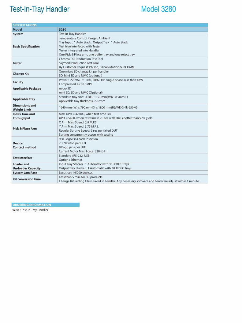
Test-In-Tray Handler Model 3280
SPECIFICATIONSModel 3280System Test-In-Tray Handler
Basic Specification
Temperature Control Range : Ambient Tray Input: 1 Auto Stack. Output Tray : 1 Auto StackTest hive interfaced with TesterTester integrated into HandlerOne Pick & Place arm, one buffer tray and one reject tray
TesterChroma TnT Production Test ToolSkymedi Production Test ToolBy Customer Request: Phison, Silicon Motion & InCOMM
Change Kit One micro SD change kit per handlerSD, Mini SD and MMC (optional)
FacilityPower : 220VAC ± 10%, 50/60 Hz, single phase, less than 4KWCompressed Air : 0.5MPa
Applicable Package
micro SDmini SD, SD and MMC (Optional)
Applicable TrayStandard tray size: JEDEC 135.9mm(W)x 315mm(L) Applicable tray thickness: 7.62mm
Dimensions andWeight Limit
1640 mm (W) x 790 mm(D) x 1800 mm(H); WEIGHT: 650KG
Index Time and Throughput
Max. UPH = 42,000, when test time is 0UPH = 5400, when test time is 70 sec with DUTs better than 97% yield
Pick & Place Arm
X Arm Max. Speed: 2.9 M.P.S.Y Arm Max. Speed: 3.75 M.P.S.Regular Sorting Speed: 6 sec per failed DUTSorting concurrently occurs with testing
Device Contact method
960 Pogo Pins each insertion7.1 Newton per DUT8 Pogo pins per DUTCurrent Motor Max. Force: 320KG F
Test InterfaceStandard : RS-232, USB Option : Ethernet
Loader and Un-loader Capacity
Input Tray Stacker : 1 Automatic with 30 JEDEC Trays Output Tray Stacker : 1 Automatic with 30 JEDEC Trays
System Jam Rate Less than 1/5000 devices
Kit conversion time Less than 5 min. for SD productsChange Kit Setting File is saved in handler. Any necessary software and hardware adjust within 1 minute
ORDERING INFORMATION
3280 : Test-In-Tray Handler

General-purpose Chassis & Backplane 15-1High Precision Source Measure Unit 15-2Device Power Supply 15-5Programmable DC Power Supply 15-6Extension Card 15-7
PXI Test & Measurement Solution
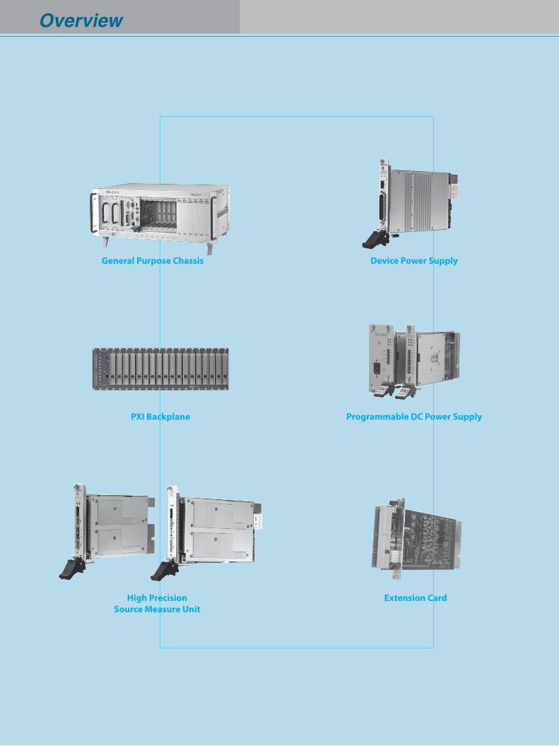
Overview
General Purpose Chassis
PXI Backplane
Extension Card
Programmable DC Power Supply
Device Power Supply
High Precision Source Measure Unit
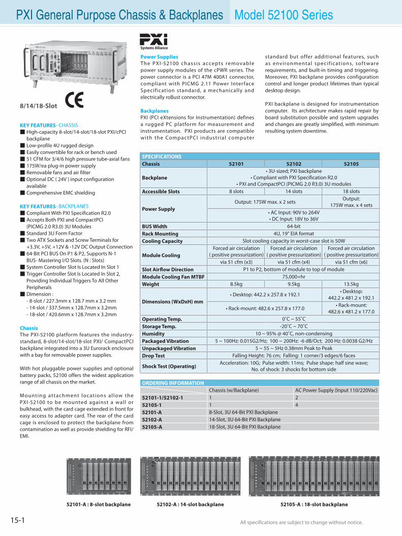
15-1 All specifications are subject to change without notice. All specifications are subject to change without notice.
PXI General Purpose Chassis & Backplanes Model 52100 Series
Power SuppliesThe PXI-52100 chass is accepts removable power supply modules of the cPWR series. The power connector is a PCI 47M 400A1 connector, compliant with PICMG 2.11 Power Inter face Specification standard, a mechanically and electrically roBust connector.
BackplanesPXI (PCI eXtensions for Instrumentation) defines a rugged PC platform for measurement and instrumentation. PXI products are compatible with the Compac tPCI industr ia l computer
8/14/18-Slot
KEY FEATURES- CHASSIS High-capacity 8-slot/14-slot/18-slot PXI/cPCI backplane Low-profile 4U rugged design Easily convertible for rack or bench used 51 CFM for 3/4/6 high pressure tube-axial fans 175W/ea plug-in power supply Removable fans and air filter Optional DC ( 24V ) input configuration
available Comprehensive EMC shielding
KEY FEATURES- BACKPLANES Compliant With PXI Specification R2.0 Accepts Both PXI and CompactPCI (PICMG 2.0 R3.0) 3U Modules Standard 3U Form Factor Two ATX Sockets and Screw Terminals for +3.3V, +5V, +12V & -12V DC Output Connection 64-Bit PCI BUS On P1 & P2, Supports N-1 BUS- Mastering I/O Slots. (N : Slots) System Controller Slot Is Located In Slot 1 Trigger Controller Slot Is Located In Slot 2, Providing Individual Triggers To All Other Peripherals Dimension : - 8-slot / 227.3mm x 128.7 mm x 3.2 mm - 14-slot / 337.5mm x 128.7mm x 3.2mm - 18-slot / 420.6mm x 128.7mm x 3.2mm
ChassisThe PXI-52100 platform features the industry- standard, 8-slot/14-slot/18-slot PXI/ CompactPCI backplane integrated into a 3U Eurorack enclosure with a bay for removable power supplies.
With hot pluggable power supplies and optional battery packs, 52100 offers the widest application range of all chassis on the market.
Mounting attachment locat ions al low the PXI-52100 to be mounted against a wall or bulkhead, with the card cage extended in front for easy access to adapter card. The rear of the card cage is enclosed to protect the backplane from contamination as well as provide shielding for RFI/EMI.
standard but offer additional features, such as environmental specif icat ions, sof tware requirements, and built-in timing and triggering. Moreover, PXI backplane provides configuration control and longer product lifetimes than typical desktop design.
PXI backplane is designed for instrumentation computer. Its architecture makes rapid repair by board substitution possible and system upgrades and changes are greatly simplified, with minimum resulting system downtime.
SPECIFICATIONSChassis 52101 52102 52105
Backplane• 3U-sized; PXI backplane
• Compliant with PXI Specification R2.0 • PXI and CompactPCI (PICMG 2.0 R3.0) 3U modules
Accessible Slots 8 slots 14 slots 18 slots
Power SupplyOutput: 175W max. x 2 sets Output:
175W max. x 4 sets• AC Input: 90V to 264V • DC Input: 18V to 36V
BUS Width 64-bitRack Mounting 4U, 19" EIA formatCooling Capacity Slot cooling capacity in worst-case slot is 50W
Module CoolingForced air circulation
( positive pressurization) Forced air circulation
( positive pressurization) Forced air circulation
( positive pressurization) via 51 cfm (x3) via 51 cfm (x4) via 51 cfm (x6)
Slot Airflow Direction P1 to P2, bottom of module to top of moduleModule Cooling Fan MTBF 75,000+hrWeight 8.5kg 9.5kg 13.5kg
Dimensions (WxDxH) mm• Desktop: 442.2 x 257.8 x 192.1
• Desktop: 442.2 x 481.2 x 192.1
• Rack-mount: 482.6 x 257.8 x 177.0• Rack-mount:
482.6 x 481.2 x 177.0Operating Temp. 0˚C ~ 55˚CStorage Temp. -20˚C ~ 70˚CHumidity 10 ~ 95% @ 40˚C, non-condensingPackaged Vibration 5 ~ 100Hz: 0.015G2/Hz; 100 ~ 200Hz: -6 dB/Oct; 200 Hz: 0.0038 G2/HzUnpackaged Vibration 5 ~ 55 ~ 5Hz 0.38mm Peak to PeakDrop Test Falling Height: 76 cm; Falling: 1 corner/3 edges/6 faces
Shock Test (Operating)Acceleration: 10G; Pulse width: 11ms; Pulse shape: half sine wave;
No. of shock: 3 shocks for bottom side
ORDERING INFORMATIONChassis (w/Backplane) AC Power Supply (Input 110/220Vac)
52101-1/52102-1 1 252105-1 1 452101-A 8-Slot, 3U 64-Bit PXI Backplane52102-A 14-Slot, 3U 64-Bit PXI Backplane52105-A 18-Slot, 3U 64-Bit PXI Backplane
Systems Alliance
52101-A : 8-slot backplane 52105-A : 18-slot backplane52102-A : 14-slot backplane
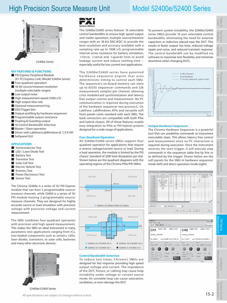
15-2All specifications are subject to change without notice. All specifications are subject to change without notice.
Flat PanelD
isplayPow
er Electronics
Electrical Safety
General
PurposePassive
Component
Semiconductor/
ICBattery Test & Autom
ationAutom
atedO
ptical Inspection Photovoltaic Test
& Automation
PXI Test &
Measurem
ent Video & Color
LED/
LightingO
ptical D
evicesIntelligent
Manufacturing System
Turnkey Test & Autom
ation High Precision Source Measure Unit Model 52400e/52400 Series
The 52400e/52400 series feature: 16 selectable control bandwidths to ensure high speed output and stable operation; multiple source/measure ranges with an 18-bit DAC/ADC to provide the best resolution and accuracy available with a sampling rate up to 100K s/S; programmable internal series resistance for battery simulation; ±force, ±sense and ±guards lines to avoid leakage current and reduce settling time -- especially useful for low current test applications.
T h e 524 0 0 e/524 0 0 s e r i e s h a v e p a t e n t e d h a r d w a r e s e q u e n c e e n g i n e t h a t u s e s determinist ic t iming to control each SMU. The sequencer's on-board memory can store up to 65535 sequencer commands and 32k measurement samples per channel, allowing cross module/card synchronization and latency free output control and measurement. No PC communication is required during execution of the hardware sequencer test process.C, C#, LabView, LabWindows APIs and versatile soft front panels come standard with each SMU. The back connectors are compatible with both PXIe and hybrid chassis. All of these features enable easy integration to PXIe or PXI-hybrid systems designed for a wide range of applications.
Four Quadrant OperationAll 52400e/52400 series SMUs suppor t four quadrant operation for applications that require a reverse voltage/current source or load. During a load operation, the module is limited by the PXI chassis' standard of 20W heat dissipation per slot. Shown below are the quadrant diagrams with the operating regions of the Chroma PXIe/PXI SMUs.
Control Bandwidth SelectionTo r e d u ce te s t t i m e s, Ch r o m a's SM Us a r e designed for fast response providing high speed output voltage and current. The impedance of the DUT, fixture, or cabling may cause loop instabilit y under voltage or current source mode. An unstable loop can cause saturation, oscillation, or even damage the DUT.
KEY FEATURES & FUNCTIONS PXI Express Peripheral Module (X1 PCI Express Link) (Model 52400e Series) Four quadrant operation 18-bit source/measure resolution (multiple selectable ranges) Low output noise High measurement speed (100k s/S) High output slew rate Optional measurement log DIO/Trigger bits Output profiling by hardware sequencer Programmable output resistance Floating & Guarding output 16 Control Bandwidth Selection Master / Slave operation Driver with LabView/LabWindows & C/C# API Softpanel GUI
APPLICATIONS Semiconductor Test LED / Laser Diode Test Battery Test Transistor Test Solar Cell Test Electric Vehicle Test Avionics Test Power Electronics Test Sensor Test
The Chroma 52400e is a series of 3U PXI Express module that can host 2 programmable source/measure channels, while 52400 is a series of 3U PXI module hosting 2 programmable source/measure channels. They are designed for highly accurate source or load simulation with precision voltage with precision voltage and current measurement.
The SMU combines four-quadrant operation with precision and high speed measurement. This makes the SMU an ideal instrument in many parametric test applications ranging from ICs, two-leaded components such as sensors, LEDs, laser diodes, transistors, to solar cells, batteries and many other electronic devices.
Systems Alliance
To prevent system instability, the 52400e/52400 series SMUs provide 16 user selectable control bandwidths, eliminating the need for external capacitors or inductors placed near the DUT. This results in faster output rise time, reduced voltage ripple and noise, and reduced transient response. The control bandwidth can be modif ied via software to maximize test flexibility and minimize downtime when changing DUTs.
Unique Hardware SequencerThe Chroma Hardware Sequencer is a powerful tool that can predefine commands as instrument executable steps. This allows latency free control and measurement since no PC interaction is required during execution. Once the instrument receives the start trigger, it will execute step commands in the sequencer table line by line or as defined by the trigger. Shown below are the soft panels for the SMU in hardware sequencer mode (left) and direct operation mode (right).
I
V
5W Load
5W Load
5W Source
5W Source
200 mA
-25V
25V
52401e-25-200m/52401-25-200m
-200 mA
10W Load
10W Load
25W Source
25W Source
1A
-25V25V
52405e-10-2/52405-10-252405e-25-3/52405-25-3
52405e-25-1/52405-25-1 52405e-5-3/52405-5-3
3.5A
2.5A
-3.5A
-2.5A
-10V -5V5V 10V
-1A
I
V
52400e Series
52400e/52400 Series
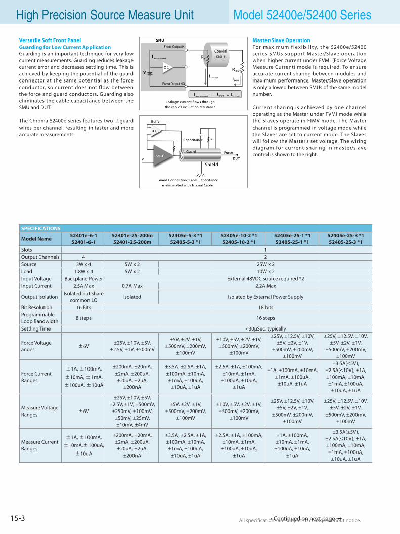
15-3 All specifications are subject to change without notice. All specifications are subject to change without notice.• Continued on next page
Versatile Soft Front PanelGuarding for Low Current ApplicationGuarding is an important technique for very-low current measurements. Guarding reduces leakage current error and decreases settling time. This is achieved by keeping the potential of the guard connector at the same potential as the force conductor, so current does not f low between the force and guard conductors. Guarding also eliminates the cable capacitance between the SMU and DUT.
The Chroma 52400e series features two ±guard wires per channel, resulting in faster and more accurate measurements.
High Precision Source Measure Unit Model 52400e/52400 Series
Master/Slave OperationFor maximum f lexibi l i t y, the 52400e/52400 series SMUs support Master/Slave operation when higher current under FVMI (Force Voltage Measure Current) mode is required. To ensure accurate current sharing between modules and maximum performance, Master/Slave operation is only allowed between SMUs of the same model number.
Current sharing is achieved by one channel operating as the Master under FVMI mode while the Slaves operate in FIMV mode. The Master channel is programmed in voltage mode while the Slaves are set to current mode. The Slaves will follow the Master's set voltage. The wiring diagram for current sharing in master/slave control is shown to the right.
SPECIFICATIONS
Model Name52401e-6-152401-6-1
52401e-25-200m52401-25-200m
52405e-5-3 *152405-5-3 *1
52405e-10-2 *152405-10-2 *1
52405e-25-1 *152405-25-1 *1
52405e-25-3 *152405-25-3 *1
Slots 1Output Channels 4 2Source 3W x 4 5W x 2 25W x 2Load 1.8W x 4 5W x 2 10W x 2Input Voltage Backplane Power External 48VDC source required *2Input Current 2.5A Max 0.7A Max 2.2A Max
Output IsolationIsolated but share
common LOIsolated Isolated by External Power Supply
Bit Resolution 16 Bits 18 bitsProgrammableLoop Bandwidth
8 steps 16 steps
Settling Time <30µSec, typically
Force Voltage anges ±6V
±25V, ±10V, ±5V, ±2.5V, ±1V, ±500mV
±5V, ±2V, ±1V, ±500mV, ±200mV,
±100mV
±10V, ±5V, ±2V, ±1V, ±500mV, ±200mV,
±100mV
±25V, ±12.5V, ±10V, ±5V, ±2V, ±1V,
±500mV, ±200mV, ±100mV
±25V, ±12.5V, ±10V, ±5V, ±2V, ±1V,
±500mV, ±200mV, ±100mV
Force Current Ranges
±1A, ±100mA,
±10mA, ±1mA,
±100uA, ±10uA
±200mA, ±20mA, ±2mA, ±200uA, ±20uA, ±2uA,
±200nA
±3.5A, ±2.5A, ±1A, ±100mA, ±10mA, ±1mA, ±100uA,
±10uA, ±1uA
±2.5A, ±1A, ±100mA, ±10mA, ±1mA,
±100uA, ±10uA, ±1uA
±1A, ±100mA, ±10mA, ±1mA, ±100uA,
±10uA, ±1uA
±3.5A(≤5V), ±2.5A(≤10V), ±1A, ±100mA, ±10mA, ±1mA, ±100uA,
±10uA, ±1uA
Measure Voltage Ranges ±6V
±25V, ±10V, ±5V, ±2.5V, ±1V, ±500mV,
±250mV, ±100mV, ±50mV, ±25mV, ±10mV, ±4mV
±5V, ±2V, ±1V, ±500mV, ±200mV,
±100mV
±10V, ±5V, ±2V, ±1V, ±500mV, ±200mV,
±100mV
±25V, ±12.5V, ±10V, ±5V, ±2V, ±1V,
±500mV, ±200mV, ±100mV
±25V, ±12.5V, ±10V, ±5V, ±2V, ±1V,
±500mV, ±200mV, ±100mV
Measure Current Ranges
±1A, ±100mA,
±10mA,±100uA,
±10uA
±200mA, ±20mA, ±2mA, ±200uA, ±20uA, ±2uA,
±200nA
±3.5A, ±2.5A, ±1A, ±100mA, ±10mA, ±1mA, ±100uA,
±10uA, ±1uA
±2.5A, ±1A, ±100mA, ±10mA, ±1mA,
±100uA, ±10uA,±1uA
±1A, ±100mA, ±10mA, ±1mA,
±100uA, ±10uA, ±1uA
±3.5A(≤5V), ±2.5A(≤10V), ±1A, ±100mA, ±10mA, ±1mA, ±100uA,
±10uA, ±1uA
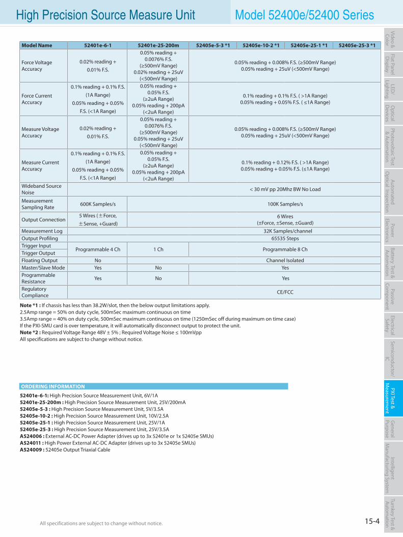
15-4All specifications are subject to change without notice. All specifications are subject to change without notice.
Flat PanelD
isplayPow
er Electronics
Electrical Safety
General
PurposePassive
Component
Semiconductor/
ICBattery Test & Autom
ationAutom
atedO
ptical Inspection Photovoltaic Test
& Automation
PXI Test &
Measurem
ent Video & Color
LED/
LightingO
ptical D
evicesIntelligent
Manufacturing System
Turnkey Test & Autom
ation
ORDERING INFORMATION
High Precision Source Measure Unit Model 52400e/52400 Series
52401e-6-1: High Precision Source Measurement Unit, 6V/1A52401e-25-200m : High Precision Source Measurement Unit, 25V/200mA52405e-5-3 : High Precision Source Measurement Unit, 5V/3.5A52405e-10-2 : High Precision Source Measurement Unit, 10V/2.5A52405e-25-1 : High Precision Source Measurement Unit, 25V/1A52405e-25-3 : High Precision Source Measurement Unit, 25V/3.5AA524006 : External AC-DC Power Adapter (drives up to 3x 52401e or 1x 52405e SMUs)A524011 : High Power External AC-DC Adapter (drives up to 3x 52405e SMUs)A524009 : 52405e Output Triaxial Cable
Model Name 52401e-6-1 52401e-25-200m 52405e-5-3 *1 52405e-10-2 *1 52405e-25-1 *1 52405e-25-3 *1
Force Voltage Accuracy
0.02% reading +
0.01% F.S.
0.05% reading + 0.0076% F.S.
(≥500mV Range)0.02% reading + 25uV
(<500mV Range)
0.05% reading + 0.008% F.S. (≥500mV Range)0.05% reading + 25uV (<500mV Range)
Force Current Accuracy
0.1% reading + 0.1% F.S.(1A Range)
0.05% reading + 0.05% F.S. (<1A Range)
0.05% reading +0.05% F.S.
(≥2uA Range)0.05% reading + 200pA
(<2uA Range)
0.1% reading + 0.1% F.S. ( >1A Range)0.05% reading + 0.05% F.S. ( ≤1A Range)
Measure Voltage Accuracy
0.02% reading +
0.01% F.S.
0.05% reading + 0.0076% F.S.
(≥500mV Range)0.05% reading + 25uV
(<500mV Range)
0.05% reading + 0.008% F.S. (≥500mV Range)0.05% reading + 25uV (<500mV Range)
Measure Current Accuracy
0.1% reading + 0.1% F.S.(1A Range)
0.05% reading + 0.05% F.S. (<1A Range)
0.05% reading + 0.05% F.S.
(≥2uA Range)0.05% reading + 200pA
(<2uA Range)
0.1% reading + 0.12% F.S. ( >1A Range)0.05% reading + 0.05% F.S. (≤1A Range)
Wideband Source Noise < 30 mV pp 20Mhz BW No Load
Measurement Sampling Rate 600K Samples/s 100K Samples/s
Output Connection5 Wires (±Force,
±Sense, +Guard)6 Wires
(±Force, ±Sense, ±Guard)
Measurement Log 32K Samples/channelOutput Profiling 65535 StepsTrigger Input
Programmable 4 Ch 1 Ch Programmable 8 ChTrigger OutputFloating Output No Channel IsolatedMaster/Slave Mode Yes No YesProgrammable Resistance Yes No Yes
Regulatory Compliance CE/FCC
Note *1 : If chassis has less than 38.2W/slot, then the below output limitations apply.2.5Amp range = 50% on duty cycle, 500mSec maximum continuous on time3.5Amp range = 40% on duty cycle, 500mSec maximum continuous on time (1250mSec off during maximum on time case)If the PXI-SMU card is over temperature, it will automatically disconnect output to protect the unit.Note *2 : Required Voltage Range 48V ± 5% ; Required Voltage Noise ≤ 100mVppAll specifications are subject to change without notice.
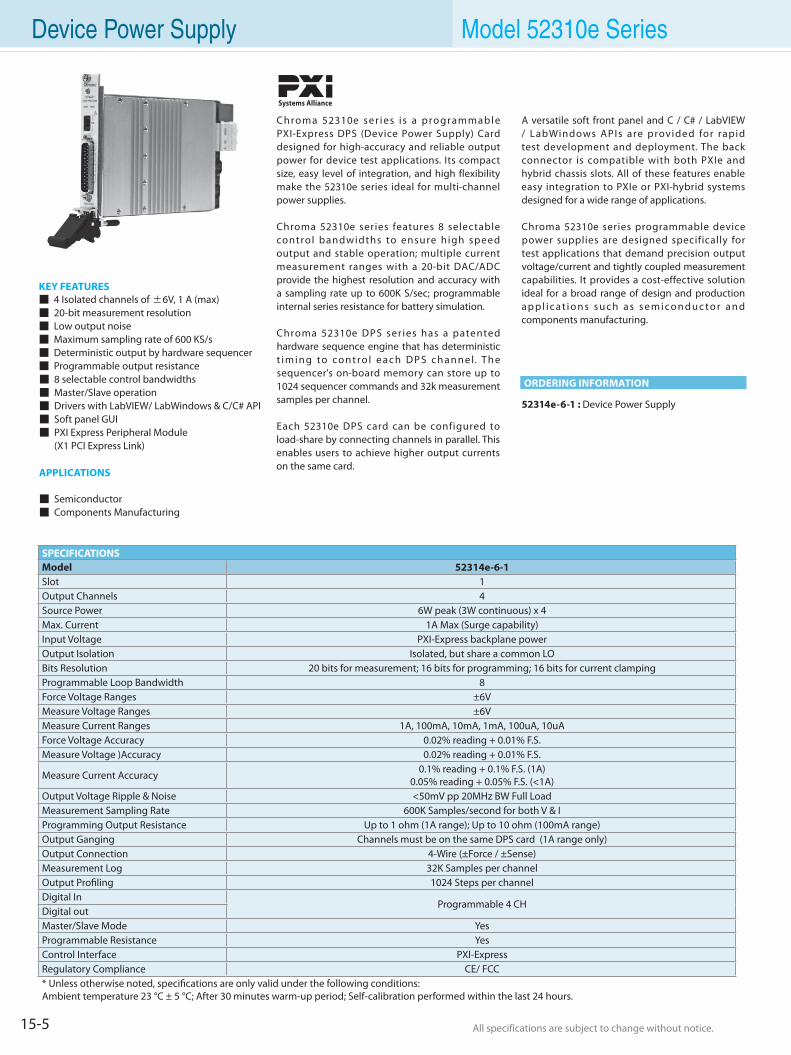
15-5 All specifications are subject to change without notice. All specifications are subject to change without notice.
Device Power Supply Model 52310e Series
Chroma 52310e ser ies i s a programmable PXI-Express DPS (Device Power Supply) Card designed for high-accuracy and reliable output power for device test applications. Its compact size, easy level of integration, and high flexibility make the 52310e series ideal for multi-channel power supplies.
Chroma 52310e series features 8 selectable control bandwidths to ensure high speed output and stable operation; multiple current measurement ranges with a 20-bit DAC/ADC provide the highest resolution and accuracy with a sampling rate up to 600K S/sec; programmable internal series resistance for battery simulation.
Chroma 52310e DPS ser ies has a patented hardware sequence engine that has deterministic t i m i n g to co n t ro l e a c h D P S c h a n n e l. Th e sequencer's on-board memory can store up to 1024 sequencer commands and 32k measurement samples per channel.
Each 52310e DPS card can be configured to load-share by connecting channels in parallel. This enables users to achieve higher output currents on the same card.
KEY FEATURES 4 Isolated channels of ±6V, 1 A (max) 20-bit measurement resolution Low output noise Maximum sampling rate of 600 KS/s Deterministic output by hardware sequencer Programmable output resistance 8 selectable control bandwidths Master/Slave operation Drivers with LabVIEW/ LabWindows & C/C# API Soft panel GUI PXI Express Peripheral Module (X1 PCI Express Link)
APPLICATIONS
Semiconductor Components Manufacturing
A versatile soft front panel and C / C# / LabVIEW / LabWindows APIs are provided for rapid test development and deployment. The back connector is compatible with both PXIe and hybrid chassis slots. All of these features enable easy integration to PXIe or PXI-hybrid systems designed for a wide range of applications.
Chroma 52310e series programmable device power supplies are designed specifically for test applications that demand precision output voltage/current and tightly coupled measurement capabilities. It provides a cost-effective solution ideal for a broad range of design and production a p p l i c a t i o n s s u c h a s s e m i c o n d u c t o r a n d components manufacturing.
Systems Alliance
SPECIFICATIONSModel 52314e-6-1Slot 1Output Channels 4Source Power 6W peak (3W continuous) x 4Max. Current 1A Max (Surge capability)Input Voltage PXI-Express backplane powerOutput Isolation Isolated, but share a common LOBits Resolution 20 bits for measurement; 16 bits for programming; 16 bits for current clampingProgrammable Loop Bandwidth 8Force Voltage Ranges ±6VMeasure Voltage Ranges ±6VMeasure Current Ranges 1A, 100mA, 10mA, 1mA, 100uA, 10uAForce Voltage Accuracy 0.02% reading + 0.01% F.S. Measure Voltage )Accuracy 0.02% reading + 0.01% F.S.
Measure Current Accuracy 0.1% reading + 0.1% F.S. (1A)0.05% reading + 0.05% F.S. (<1A)
Output Voltage Ripple & Noise <50mV pp 20MHz BW Full LoadMeasurement Sampling Rate 600K Samples/second for both V & IProgramming Output Resistance Up to 1 ohm (1A range); Up to 10 ohm (100mA range)Output Ganging Channels must be on the same DPS card (1A range only)Output Connection 4-Wire (±Force / ±Sense)Measurement Log 32K Samples per channelOutput Profiling 1024 Steps per channelDigital In
Programmable 4 CHDigital outMaster/Slave Mode YesProgrammable Resistance YesControl Interface PXI-ExpressRegulatory Compliance CE/ FCC* Unless otherwise noted, specifications are only valid under the following conditions:Ambient temperature 23 °C ± 5 °C; After 30 minutes warm-up period; Self-calibration performed within the last 24 hours.
52314e-6-1 : Device Power Supply
ORDERING INFORMATION
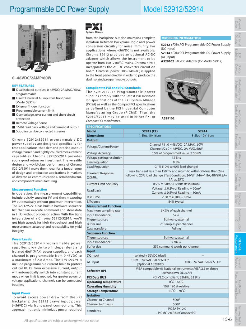
15-6All specifications are subject to change without notice. All specifications are subject to change without notice.
Flat PanelD
isplayPow
er Electronics
Electrical Safety
General
PurposePassive
Component
Semiconductor/
ICBattery Test & Autom
ationAutom
atedO
ptical Inspection Photovoltaic Test
& Automation
PXI Test &
Measurem
ent Video & Color
LED/
LightingO
ptical D
evicesIntelligent
Manufacturing System
Turnkey Test & Autom
ation Programmable DC Power Supply Model 52912/52914
0~48VDC/2AMP/60W
KEY FEATURES Dual Isolated outputs; 0-48VDC/ 2A MAX./ 60W, programmable Direct Universal AC input via front panel (Model 52914) External Trigger function Programmable current limit Over voltage, over current and short circuit protection Remote Voltage Sense 16 Bit read back voltage and current at output Supplies can be connected in series
C h r o m a 52912/52914 p r o g r a m m a b l e D C power supplies are designed specifically for test applications that demand precise output voltage/current and tightly coupled measurement capabil it ies. Chroma 52912/52914 provides you a good return on investment. The versatile design and world-class performance of Chroma 52912/52914 make them ideal for a broad range of design and production applications in markets as diverse as communications, semiconductor, and components manufacturing.
Measurement Function In operation, the measurement capabilities include quickly sourcing I/V and then measuring I/V automatically without processor intervention. The 52912/52914 has built-in hardware sequence list that can execute command and store data in FIFO without processor action. With the tight integration of a Chroma 52912/52914, you'll get high speeds for high throughput and high measurement accuracy and repeatability for yield integrity.
Power LevelsT h e 5 2 9 1 2 / 5 2 9 1 4 P r o g r a m m a b l e p o w e r s u p p l i e s p r o v i d e t w o i n d e p e n d e n t a n d isolated 60W (MAX) power supplies, and each channel is programmable from 0-48VDC to a maximum of 2.0 Amps. The 52912/52914 include programmable current limit to protect critical UUT's from excessive current, output will automatically switch into constant current mode when limit is reached. For greater power or voltage applications, channels can be connected in series.
Input PowerTo avoid excess power draw from the PXI b a c k p l a n e, t h e 52912 d raws i n p u t p owe r (+56VDC) via front panel connections. This approach not only minimizes power required
52912 : PXI/cPCI Programmable DC Power Supply (DC Input)52914 : PXI/cPCI Programmable DC Power Supply (AC Input)A529102 : AC/DC Adapter (for Model 52912)
A529102
from the backplane but also maintains complete isolation between backplane logic and power conversion circuitry for noise immunity. For applications where +56VDC is not available, Chroma 52912 provides an optional AC-DC adapter which allows the instrument to be operate from 100~240VAC mains. Chroma 52914 incorporates the AC-DC converter circuit on board. Universal power (100~240VAC) is applied to the front panel directly in order to produce the dual isolated programmable outputs.
Compliant to PXI and cPCI StandardsT h e 5 2 9 1 2 / 5 2 9 1 4 P r o g r a m m a b l e p o w e r supplies comply with the latest PXI Revision 2.0 specifications of the PXI System Alliance (PXISA) as well as the CompactPCI specifications as defined by the PCI Industrial Computer M a n u f a c t u r i n g G ro u p (P I C M G). Th u s, t h e 52912/52914 may be used in either PXI or CompactPCI mainframes.
SPECIFICATIONSModel 52912 (CE) 52914Dimensions 1-Slot, 10x16cm 3-Slot, 10x16cmOutput
Voltage/Current/PowerChannel #1 : 0 ~ 48VDC, 2A MAX., 60WChannel #2 : 0 ~ 48VDC, 2A MAX, 60W
Voltage Accuracy 0.5% of programmed value ±50mVVoltage setting resolution 12 BitsLine Regulation 0.1%Load Regulation 0.1% (10% to 90% load change)
Transient Response (20MHz)
Peak transient less than 150mV and return to within 5% less than 2ms following 20% load change. (Test Condition: [email protected]~1.8A, [email protected]~
1A) at 25˚CCurrent Limit Accuracy 0.5% ± 50mA (12 Bits Resolution)
Read backVoltage: ±0.2% of Reading + 60mV Current: ±0.5% of Reading + 10mA
Rise Time < 50 ms (10% ~ 90%)Efficiency 84% typicalMeasurement FunctionMaximum sampling rate 5K S/s of each channelInput Impedance 5kΩTrigger sources Software, externalBuffer size 2K samples per channelData transfers PollingSequence FunctionTrigger sources Software, externalInput Impedance 3.78kΩBuffer size 256 command words per channelInputDC Input Isolated + 56VDC (dual) --
AC Input100V ~ 240VAC, 50 or 60 Hz
(Optional A529102)100 ~ 240VAC, 50 or 60 Hz
Software API• VISA compatible via National Instrument's VISA 2.5 or above
• 20 Windows DLL's APIPCI Data BUS PCI V2.2 compliant, 33MHz, 32 BitsOperating Temperature 0˚C ~ 55˚COperating Humidity 10% ˜ 90 % relativeStorage Temperature -30˚C ~ 70˚CIsolationChannel to Channel 500VChannel to Chassis 500V
Standards• PXISA PXI 2.0
• PICMG 2.0 R3.0 CompactPCI
ORDERING INFORMATION
Systems Alliance
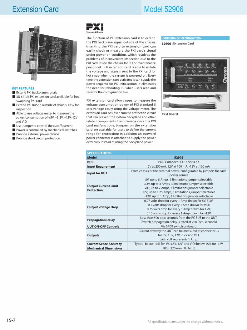
15-7 All specifications are subject to change without notice. All specifications are subject to change without notice.
The function of PXI extension card is to extend the PXI backplane signal outside of the chassis. Inserting the PXI card to extension card can easily check or measure the PXI card's signal under power on condition, which resolves the problems of inconvenient inspection due to the PXI card inside the chassis for RD or maintenance personnel. PXI extension card is able to isolate the voltage and signals sent to the PXI card for hot swap when the system is powered on. Every time the extension card activates it can supply the power required for PXI initialization. It eliminates the need for rebooting PC when users read and re-write the configuration files.
PXI extension card allows users to measure the voltage consumption power of PXI standard 5 sets voltage easily using the voltage meter. The extension card has over current protection circuit that can prevent the system backplane and other related components from damage once the PXI card malfunctions. Jumpers on the extension card are available for users to define the current range for protection; in addition an outward power connector is attached to supply the power externally instead of using the backplane power.
KEY FEATURES Extend PXI backplane signals 3U 64-bit PXI extension card available for hot
swapping PXI card Extend PXI BUS to outside of chassis, easy for
inspection Able to use voltage meter to measure the
power consumption of +5V, +3.3V, +12V,-12V and VIO Use Jumper to control the cutoff current Power is controlled by mechanical switches Provide external power device Provide short circuit protection
52906 : Extension Card
SPECIFICATIONSModel 52906BUS PXI / Compact PCI 32 or 64 bitInput Requirement 5V at 250 mA, 12V at 100 mA, -12V at 100 mA
Input for UUT From chassis or the external power, configurable by jumpers for each
power source
Output Current Limit Protection
5V, up to 5 Amps, 3 limitations jumper selectable 3.3V, up to 3 Amps, 3 limitations jumper selectable VIO, up to 2 Amps, 3 limitations jumper selectable
12V, up to 1.25 Amps, 3 limitations jumper selectable -12V, up to 1 Amp, 3 limitations jumper selectable
Output Voltage Drop
0.07 volts drop for every 1 Amp drawn for 5V, 3.3V;0.1 volts drop for every 1 Amp drawn for VIO;
0.25 volts drop for every 1 Amp drawn for 12V; 0.15 volts drop for every 1 Amp drawn for -12V
Propagation Delay Less than 500 pico-seconds from the PC BUS to the UUT. (Switch propagation delay is rated at 250 Pico-seconds)
UUT ON-OFF Controls Via SPDT switch on-board
Outputs Current draw by the UUT can be measured at connector J5
for 5V, 3.3V, 12V, -12V and VIO. Each volt represents 1 Amp.
Current Sense Accuracy Typical below 10% for 5V, 3.3V, 12V, and VIO; below 15% for -12VMechanical Dimensions 100 x 220 mm (3U high)
Test Board
ORDERING INFORMATION
Extension Card Model 52906
Systems Alliance
15-8All specifications are subject to change without notice. All specifications are subject to change without notice.
Flat PanelD
isplayPow
er Electronics
Electrical Safety
General
PurposePassive
Component
Semiconductor/
ICBattery Test & Autom
ationAutom
atedO
ptical Inspection Photovoltaic Test
& Automation
PXI Test &
Measurem
ent Video & Color
LED/
LightingO
ptical D
evicesIntelligent
Manufacturing System
Turnkey Test & Autom
ation
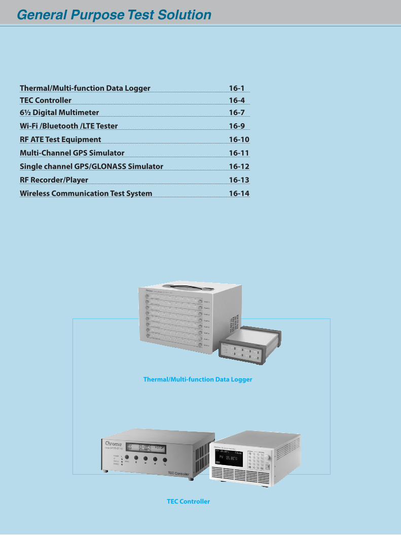
General Purpose Test Solution
Thermal/Multi-function Data Logger
TEC Controller
Thermal/Multi-function Data Logger 16-1TEC Controller 16-46½ Digital Multimeter 16-7
Wi-Fi /Bluetooth /LTE Tester 16-9
RF ATE Test Equipment 16-10
Multi-Channel GPS Simulator 16-11
Single channel GPS/GLONASS Simulator 16-12
RF Recorder/Player 16-13
Wireless Communication Test System 16-14
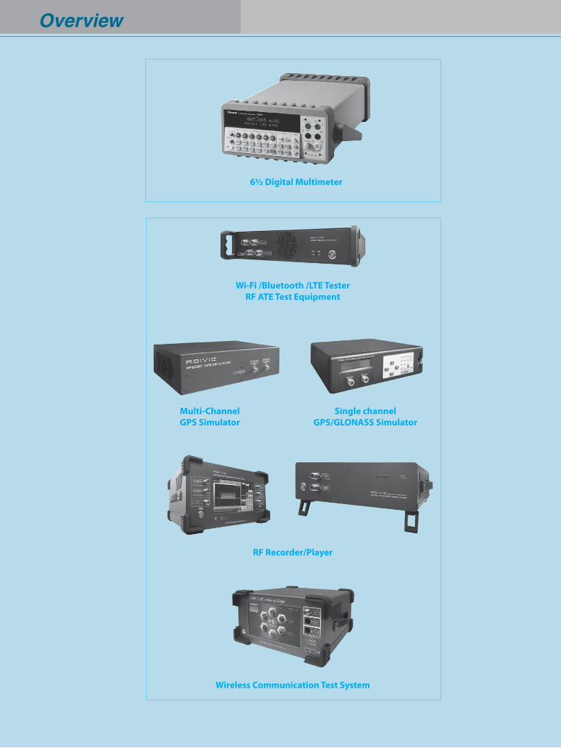
Overview
Wi-Fi /Bluetooth /LTE TesterRF ATE Test Equipment
Multi-ChannelGPS Simulator
Single channelGPS/GLONASS Simulator
RF Recorder/Player
Wireless Communication Test System
6½ Digital Multimeter
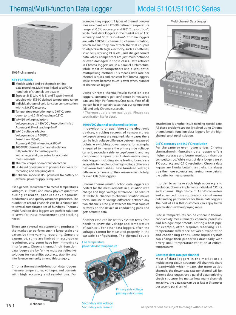
16-1 All specifications are subject to change without notice. All specifications are subject to change without notice.
Thermal/Multi-function Data Logger Model 51101/51101C Seriesexample, they support 8 types of thermal couples measurement with ITS-90 defined temperature range at 0.5˚C accuracy and 0.01˚C resolution*, while most data loggers in the market are at 1 ˚C accuracy and 0.1˚C resolution*. Chroma loggers are with 1000VDC channel to channel isolation, which means they can attach thermal couples to objects with high electricity, such as batteries, solar cells, working PCB, etc., and still get correct data. Many competitors are just malfunctioned or even damaged in those cases. Data retrieve in Chroma loggers are in a parallel architecture, while most of competitors use a sequential multiplexing method. This means data rate per channel is quick and constant for Chroma loggers, while others become much slower when number of channels is bigger.
Using Chroma thermal/multi-function data loggers, customers get confidence in measured data and high Performance/Cost ratio. Most of all, we can help in certain cases that our competitors fail, and only Chroma succeeds.* Thermocouple error excluded. Please see specification list for detail.
1000VDC channel to channel isolationIn developing or qualifying some electronic devices, tracking records of temperatures/voltages/currents are required. Many cases there can be high voltage difference between measured points. A switching power supply, for example, is required to measure the primary side voltage/current, secondary side voltage/current, and key component temperatures. Unfortunately, many data loggers including some leading brands are incapable to handle such a high voltage difference between both sid es. Few hundred voltage difference can mess up their measurement totally, or even kills their loggers.
Chroma thermal/multifunction data loggers are perfect for the measurements in a situation with charge and high voltage difference. The feature of 1000VDC channel to channel isolation makes them immune to voltage difference between any two channels. One just attaches thermal couples or wires on the device or conducting pads and gets accurate data.
Another case can be battery system tests. One needs to know the voltage and temperature of each cell. For other data loggers, often the voltages cannot be measured properly in the cascade configuration. The thermal couple
8/64 channels
KEY FEATURES Models with 8 and 64 channels on-line data recording. Multi-sets linked to a PC for hundreds of channels are doable Support B, E, J, K, N, R, S, and T type thermal couples with ITS-90 defined temperature range Individual channel cold junction compensation with <±0.3˚C accuracy Temperature resolution up to 0.01˚C, error down to ±(0.01% of reading+0.3˚C) VA-480 voltage adaptor : Voltage range ±480VDC ; Resolution 1mV ; Accuracy 0.1% of reading+1mV VA-10 voltage adaptor : Voltage range ±10VDC ; Resolution 100uV ; Accuracy 0.05% of reading+500uV 1000VDC channel to channel isolation, full protection for testing points with charge and guarantee for accurate measurements Thermal couple open circuit detection PC-based operation with powerful software for recording and analyzing data 8 channel model is USB powered. No battery or external power supply is required
It is a general requirement to record temperatures, voltages, currents, and many physics quantities d u r i n g r e s e a r c h, p r o d u c t d e v e l o p m e n t, productions, and quality assurance processes. The number of record channels can be a simple one to several complicated set of hundreds. Thermal/multi-function data loggers are prefect solutions to serve for these measurement and tracking needs.
There are several measurement products in the market to perform such a large-scale and extensive time varying recording. Some are expensive, some are l imited in accuracy or resolution, and some have low immunity to interference. Chroma thermal/multi-function data loggers are by far the most cost-effective solutions for versatility, accuracy, stability, and interference immunity among this category.
Chroma thermal/multi-function data loggers measure temperatures, voltages, and currents with h igh accurac y and resolut ions. For
attachment is another issue needing special care. All these problems are easily solved using Chroma thermal/multi-function data loggers for the high channel to channel isolation.
0.5˚C accuracy and 0.01˚C resolutionFor the same or even lower prices, Chroma thermal/mult i-func tion data logger offers higher accuracy and better resolution than our competitors do. While most of data loggers are at 1˚C accuracy and 0.1˚C resolution, Chroma data loggers are 1 order better than theirs. It is always true the more accurate and seeing more details, the better for measurements.
In order to achieve such high accuracy and resolution, Chroma implements individual CJC for each channel. High bit-count A-to-D converters and advanced noise suppression circuit makes outstanding performance for these data loggers. The best of all is that customers can enjoy better specifications without paying more.
Precise temperatures can be critical in thermal conductivity measurements, chemical processes, and biologic experiments. Testing a heat pipe, for example, often requires resolving <1˚C temperature difference between evaporation and condensing zones. Some liquid crystals can change their properties drastically with a very small temperature variation at critical temperatures.
Constant data rate per channelM ost of data loggers in the mar ket use a multiplexing circuit structure. All channels share a bandwidth which means the more active channels, the slower data rate per channel will be. Chroma data loggers use a parallel data retrieving circuit structure. No matter how many channels are active, the data rate can be as fast as 5 samples per second per channel.
8 channels
Coil temperaturepower device temparature
Primary side voltageprimary side current
Secondary side voltageSecondary side current
Multi-channel Data Logger
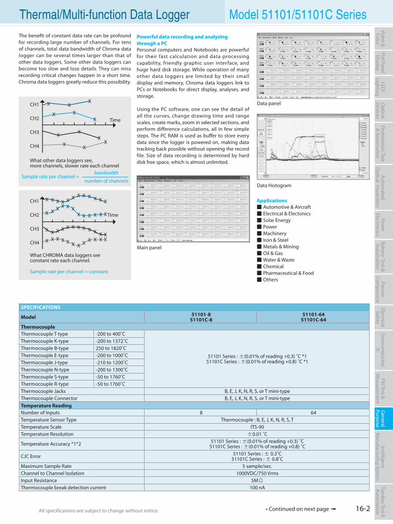
16-2All specifications are subject to change without notice. All specifications are subject to change without notice.
Flat PanelD
isplayPow
er Electronics
Electrical Safety
General
PurposePassive
Component
Semiconductor/
ICBattery Test & Autom
ationAutom
atedO
ptical Inspection Photovoltaic Test
& Automation
PXI Test &
Measurem
ent Intelligent
Manufacturing System
Video & Color
Turnkey Test & Autom
ation LED
/Lighting
Optical
Devices
Thermal/Multi-function Data Logger Model 51101/51101C SeriesThe benefit of constant data rate can be profound for recording large number of channels. For tens of channels, total data bandwidth of Chroma data logger can be several times larger than that of other data loggers. Some other data loggers can become too slow and lose details. They can miss recording critical changes happen in a short time. Chroma data loggers greatly reduce this possibility.
Main panel
Data panel
Time
X XX
X XX
X XX
XXX
CH1
CH2
CH3
CH4
What other data loggers see,more channels, slower rate each channel
Time
CH1
CH2
CH3
CH4
X X X X X X X X X X X X
XXXXXXXXXXXX
X X X X X X X X X X X XXXXXXXXXXXX
What CHROMA data loggers seeconstant rate each channel.
Data Histogram
SPECIFICATIONS
Model 51101-851101C-8
51101-6451101C-64
ThermocoupleThermocouple T-type -200 to 400˚C
51101 Series : ±(0.01% of reading +0.3) ˚C *151101C Series : ±(0.01% of reading +0.8) ˚C *1
Thermocouple K-type -200 to 1372˚CThermocouple B-type 250 to 1820˚CThermocouple E-type -200 to 1000˚CThermocouple J-type -210 to 1200˚CThermocouple N-type -200 to 1300˚CThermocouple S-type -50 to 1760˚CThermocouple R-type -50 to 1760˚CThermocouple Jacks B, E, J, K, N, R, S, or T mini-typeThermocouple Connector B, E, J, K, N, R, S, or T mini-typeTemperature ReadingNumber of Inputs 8 64Temperature Sensor Type Thermocouple : B, E, J, K, N, R, S, TTemperature Scale ITS-90Temperature Resolution ±0.01 ˚C
Temperature Accuracy *1*2 51101 Series : ±(0.01% of reading +0.3) ˚C51101C Series : ±(0.01% of reading +0.8) ˚C
CJC Error 51101 Series : ± 0.3˚C51101C Series : ± 0.8˚C
Maximum Sample Rate 5 sample/sec.Channel to Channel Isolation 1000VDC/750 VrmsInput Resistance 5MΩThermocouple break detection current 100 nA
• Continued on next page
X
number of channels
bandwidth
Sample rate per channel = constant
Sample rate per channel =
Applications Automotive & Aircraft Electrical & Electonics Solar Energy Power Machinery Iron & Steel Metals & Mining Oil & Gas Water & Waste Chemical Pharmaceutical & Food Others
Powerful data recording and analyzingthrough a PCPersonal computers and Notebooks are powerful for their fast calculation and data processing capability, friendly graphic user interface, and huge hard disk storage. While operation of many other data loggers are limited by their small display and memory, Chroma data loggers link to PCs or Notebooks for direct display, analyses, and storage.
Using the PC software, one can see the detail of all the curves, change drawing time and range scales, create marks, zoom in selected sections, and perform difference calculations, all in few simple steps. The PC RAM is used as buffer to store every data since the logger is powered on, making data tracking back possible without opening the record file. Size of data recording is determined by hard disk free space, which is almost unlimited.
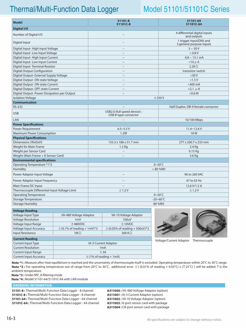
16-3 All specifications are subject to change without notice. All specifications are subject to change without notice.
Thermal/Multi-Function Data Logger Model 51101/51101C SeriesModel 51101-8
51101C-851101-64
51101C-64Digital I/O
Number of Digital I/O -- 4 differential digital inputsand outputs
Digital Input -- 1 trigger input(DI0) and 3 general purpose inputs
Digital Input- High Input Voltage -- 3 ~ 30 VDigital Input- Low Input Voltage -- < 0.8 VDigital Input- High Input Current -- 0.8 ~ 13.1 mADigital Input- Low Input Current -- <10μADigital Input- Terminal Resistor -- 2.2KΩDigital Output Configuration -- transistor switchDigital Output- External Supply Voltage -- <30 VDigital Output- ON-state Voltage -- <1.5 VDigital Output- ON-state Current -- <400 mADigital Output- OFF-state Current -- <2.1 μADigital Output- Power Dissipation per Output -- <0.6 WIsolation Voltage ±250 VCommunicationRS-232 -- Half Duplex, DB-9 female connector
USB USB2.0 (full speed device) ;USB B-type connector
LAN -- 10/100 MbpsPower SpecificationsPower Requirement 4.5~5.5 V 11.4~12.6 VMaximum Power Consumption 1.2W 18 WPhysical SpecificationsDimensions (WxDxH) 135.3 x 186 x 51.7 mm 277 x 200.7 x 233 mmWeight for Main Frame 1.2 Kg 2.4 KgWeight per Sensor Card -- 0.15 KgWeight (Main Frame + 8 Sensor Card) -- 3.6 KgEnvironmental specificationsOperating Temperature *1*2 0~50˚CHumidity < 80 %RH
Power Adaptor Input Voltage -- 90 to 260 VAC
Power Adaptor Input Frequency -- 47 to 63 Hz
Main Frame DC Input -- 12.6 V/1.5 AThermocouple Differential Input Voltage Limit ±1.2 V ±1.2 VOperating Temperature 0~50˚CStorage Temperature -20~60˚CStorage Humidity 80 %RH
Note *1 : Measure after heat equilibrium is reached and the uncertainty of thermocouple itself is excluded. Operating temperature within 20˚C to 30˚C range.Note *2 : For operating temperature out of range from 20˚C to 30˚C, additional error ±[ (0.01% of reading + 0.03˚C) x (T-25˚C) ] will be added. T is the ambient temperature.Note *3 : Under MV_8 filtering modeNote *4 : Model 51101-64/51101C-64 with LAN module
51101-8 : Thermal/Multi-Function Data Logger - 8 channel51101C-8 : Thermal/Multi-Function Data Logger - 8 channel51101-64 : Thermal/Multi-Function Data Logger - 64 channel51101C-64 : Thermal/Multi-Function Data Logger - 64 channel
A511000 : VA-480 Voltage Adaptor (option)A511001 : IA-3 Current Adaptor (option)A511002 : VA-10 Voltage Adaptor (option)A511003 : 8-port sensor card with packageA511004 : C8-port sensor card with package
ORDERING INFORMATION
Voltage/Current Adaptor Thermocouple
Voltage ReadingVoltage Input Type VA-480 Voltage Adaptor VA-10 Voltage AdaptorVoltage Resolution 1mV 100uVVoltage Input Range ±480VDC ±10VDCVoltage Input Accuracy ±(0.1% of reading + 1mV)*3 ±(0.05% of reading + 500uV)*3Input Resistance 1MΩ 300 KΩ
Current ReadingCurrent Input Type IA-3 Current AdaptorCurrent Resolution 1mACurrent Input Range ±3ACurrent Input Accuracy ±(1% of reading + 1mA)
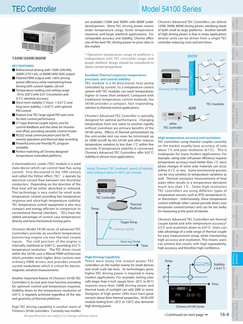
16-4All specifications are subject to change without notice. All specifications are subject to change without notice.
Flat PanelD
isplayPow
er Electronics
Electrical Safety
General
PurposePassive
Component
Semiconductor/
ICBattery Test & Autom
ationAutom
atedO
ptical Inspection Photovoltaic Test
& Automation
PXI Test &
Measurem
ent Intelligent
Manufacturing System
Video & Color
Turnkey Test & Autom
ation LED
/Lighting
Optical
Devices
TEC Controller Model 54100 Seriesare available (150W and 300W) with 800W under development. More TEC driving power means wider temperature range, faster temperature response, and larger platform applications. For comparable accuracy and stability, Chroma offers one of the best TEC driving power-to-price ratio in the market.
* Operation temperature range of platform is independent with TEC controller range, and proper platform design should be considered to obtain certain temperature.
Excellent Thermal response, temperature precision, and control stabilityTEC module is a bi-direc t ional heat pump controlled by current. So a temperature control system with TEC modules can reach temperatures higher or lower than ambient. Compared with traditional temperature control methods, the 54100 provides a compact, fast responding, solution to thermal control applications.
Chroma's Advanced TEC Controller is specially designed for optimal performance. Changing temperature from one value to another rapidly without overshoot are primary benefits of the 54100 series. Effects of thermal perturbations by the unit-under-test can even be minimized up to 100W on/off, by the 54100 and often reduces temperature variation to less than 1 within few seconds. If temperature stability is concerned, Chroma's Advanced TEC Controllers offer 0.01 stability in almost most applications.
150W/300W/800W
KEY FEATURES Bidirectional driving with 150W (24V/8A), 300W (27V/12A), or 800W (40V/20A) output Filtered PWM output with >90% driving
power efficiency while maintaining linear driving with current ripples<20 mA Temperature reading and setting range
-70 to 250with 0.01resolution and 0.3 absolute accuracy Short term stability (1 hour) ±0.01 and
long term stability ±0.05 with optimal PID control Feature true TEC large signal PID auto tune
for best control performance 2 T-type thermal couple inputs, one for
control feedback and the other for monitor and offset, providing versatile control modes RS232 serial communication port for PC
remote operation and thermal data recording Powerful and user-friendly PC program
available Perfect matching all Chroma designed
temperature controlled platforms
A thermoelectric cooler (TEC) module is a solid state device which can control heat flux using current. First discovered in the 19th century and called the Peltier effect, TEC’s operate by electrical current flow between two dissimilar conductors. Depending on the direction of the flow heat will be either absorbed or released. This technology is very useful for small scale temperature control; providing fast temperature response and ultra-high temperature stability. TEC temperature control equipment is also very compact and energy efficient in comparison to conventional thermal chambers. TECs have the added advantage of control case temperatures directly and have mechanical moving parts.
Chroma's Model 54100 series of advanced TEC Controllers provide an excellent temperature monitoring engine via two thermal couple inputs. The cold junction of the engine is internally stabilized to 0.001, providing 0.01 temperature resolution. The TEC driver circuit within the 54100 uses a filtered PWM architecture which provides much higher drive currents over ordinary PWM drivers and provides smooth current modulation which is critical for electro-magnetic sensitive measurements.
Another important feature of Chroma's 54100 TEC Controllers is its true auto tune function providing for optimum control and temperature response. Stability down to the temperature resolution of 0.01 is regularly achieved regardless of the size and geometry of thermal platforms.
High TEC driving capability is another merit of Chroma's 54100 controllers. Currently two modles
• Continued on next page
Time
Using Chroma's TEC methord, speed of heating and cooling is about 5~60 per minute.
Temp.
Start ing Temp.
Target Temp.
change rapidly
TEC Controller
Thermal Platform
High Driving CapabilityT h e r e w e r e m a ny l o w o u t p u t p o w e r T E C controllers on the market mainly for small devices and small scale lab tests. As technologies grow, higher TEC driving power is required in many modern applications. For example, testing solar cells larger than 4 inch square from -20 to 85 requires more than 100W driving power and thermal loads of sunlight can add 30W or more. Designers of high power LEDs must have great concern about their thermal properties. 30 W-LED module testing from -20 to 150 also demands high driving power.
Chroma's Advanced TEC Controllers can deliver 150W, 300W, 800W driving power, satisfying needs of both small to large platforms. Another benefit of high driving power is that in many applications several units can be driven from a single TEC controller reducing costs and test times.
High temperature accuracy and resolutionTEC controllers using thermal couples currently on the market usually have accuracy of only about 1 and poor resolution (0.1). This is inadequate for many modern applications. For example, rating solar cell power efficiency requires temperature accuracy much better than 1 since phase changes of some solar materials can occur within 0.1 or less. Some biochemical process can be very sensitive to temperature variations as well. Thermal resistance measurements of heat pipes often results in a temperature deviation much less than 1. Some high resolution TEC controllers are using different types of temperature sensors, such as RTD, temperature IC, or thermistors. Unfortunately, these temperature control methods often cannot provide direct case temperate control/contact and can be too bulky for measuring at the point of interest.
Chroma's Advanced TEC Controllers are thermal couple based and with temperature accuracy* 0.3 and resolution down to 0.01. Users can take advantage of a wide range of thermal couple for easy measurement setup, while maintaining high accuracy and resolution. This means users can achieve test results with high repeatability, high accuracy, and therefore high confidence.
Chroma 54100 Series
Time
Temp.
25
Stability±0.01
otherTEC controller
Chroma 54100 Series
60W
800W
TEC modules
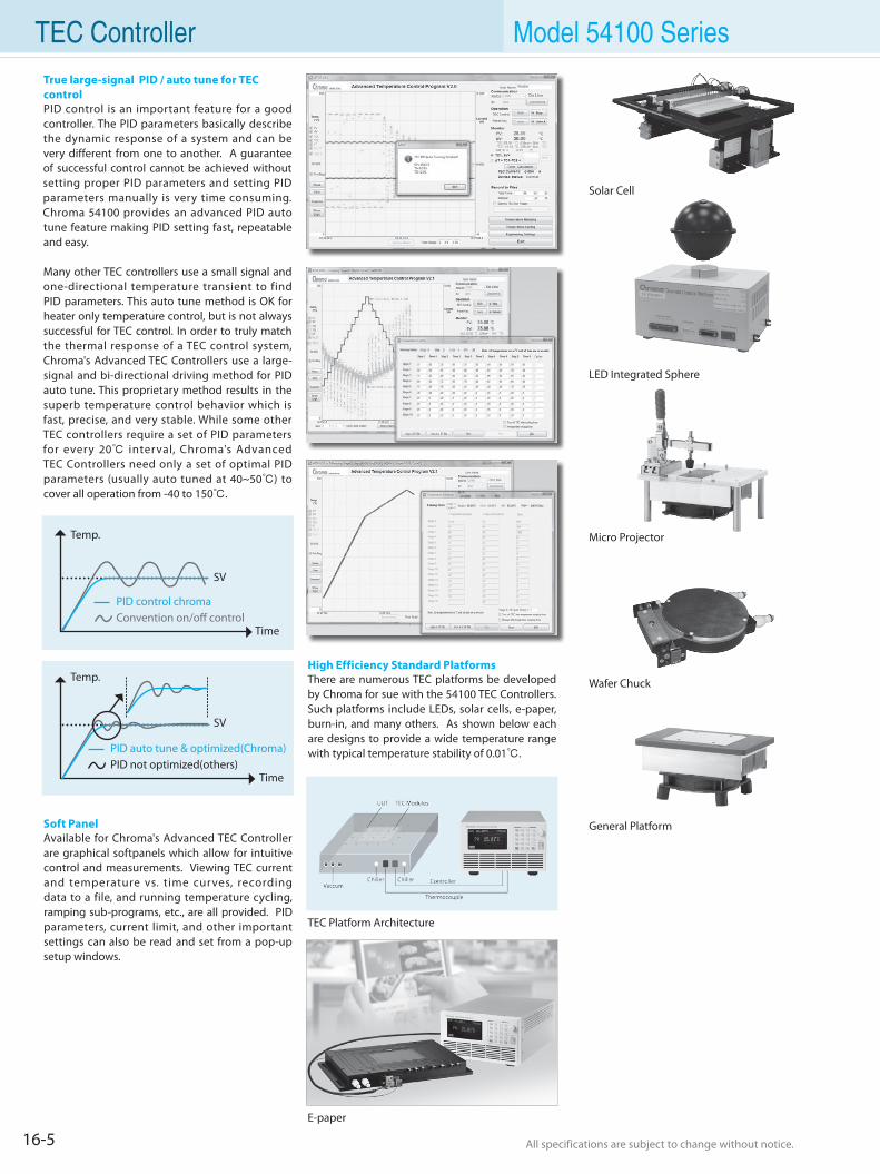
16-5 All specifications are subject to change without notice. All specifications are subject to change without notice.
TEC Controller Model 54100 SeriesTrue large-signal PID / auto tune for TEC controlPID control is an important feature for a good controller. The PID parameters basically describe the dynamic response of a system and can be very different from one to another. A guarantee of successful control cannot be achieved without setting proper PID parameters and setting PID parameters manually is very time consuming. Chroma 54100 provides an advanced PID auto tune feature making PID setting fast, repeatable and easy.
Many other TEC controllers use a small signal and one-directional temperature transient to find PID parameters. This auto tune method is OK for heater only temperature control, but is not always successful for TEC control. In order to truly match the thermal response of a TEC control system, Chroma's Advanced TEC Controllers use a large-signal and bi-directional driving method for PID auto tune. This proprietary method results in the superb temperature control behavior which is fast, precise, and very stable. While some other TEC controllers require a set of PID parameters for every 20 interval, Chroma's Advanced TEC Controllers need only a set of optimal PID parameters (usually auto tuned at 40~50) to cover all operation from -40 to 150.
Time
Temp.
SV
Convention on/off controlPID control chroma
Soft PanelAvailable for Chroma's Advanced TEC Controller are graphical softpanels which allow for intuitive control and measurements. Viewing TEC current and temperature vs. time curves, recording data to a file, and running temperature cycling, ramping sub-programs, etc., are all provided. PID parameters, current limit, and other important settings can also be read and set from a pop-up setup windows.
High Efficiency Standard PlatformsThere are numerous TEC platforms be developed by Chroma for sue with the 54100 TEC Controllers. Such platforms include LEDs, solar cells, e-paper, burn-in, and many others. As shown below each are designs to provide a wide temperature range with typical temperature stability of 0.01.
Solar Cell
Wafer Chuck
General Platform
LED Integrated Sphere
Micro Projector
Time
Temp.
SV
PID auto tune & optimized(Chroma)PID not optimized(others)
TEC Platform Architecture
E-paper
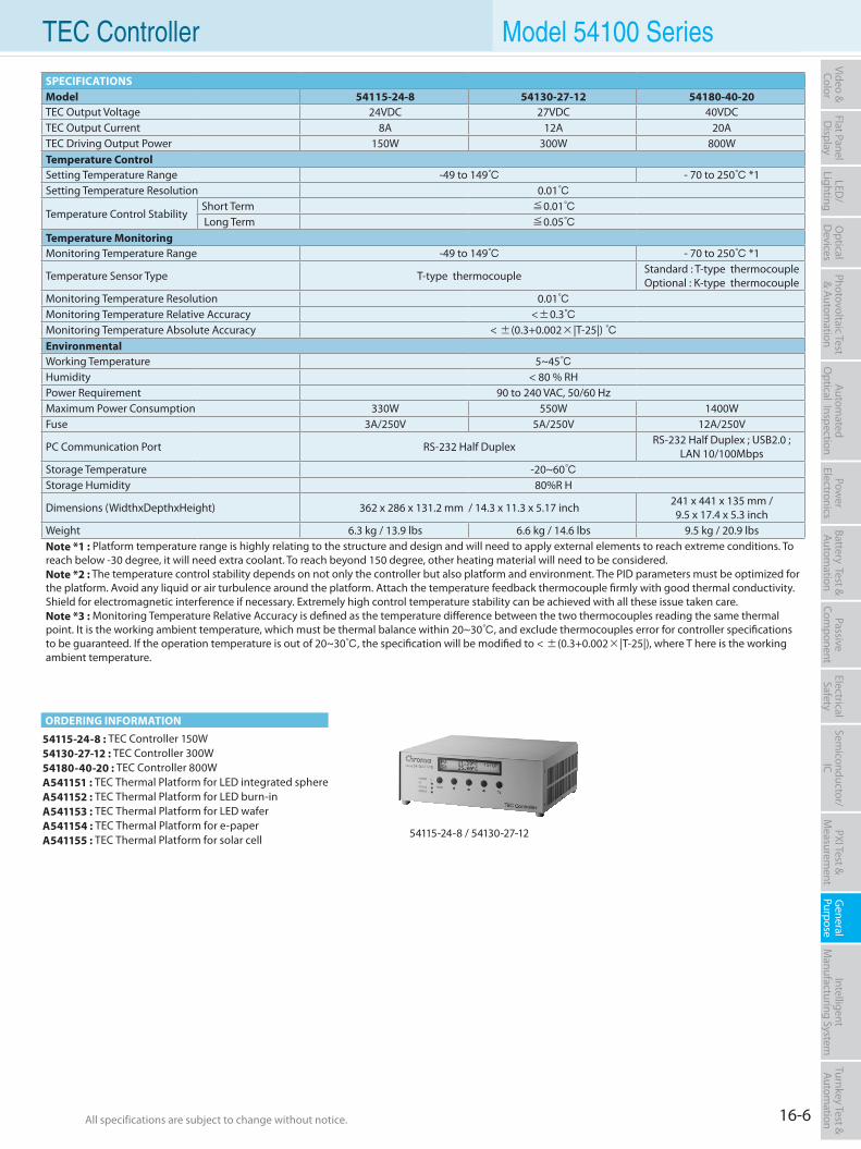
16-6All specifications are subject to change without notice. All specifications are subject to change without notice.
Flat PanelD
isplayPow
er Electronics
Electrical Safety
General
PurposePassive
Component
Semiconductor/
ICBattery Test & Autom
ationAutom
atedO
ptical Inspection Photovoltaic Test
& Automation
PXI Test &
Measurem
ent Intelligent
Manufacturing System
Video & Color
Turnkey Test & Autom
ation LED
/Lighting
Optical
Devices
TEC Controller Model 54100 Series
54115-24-8 : TEC Controller 150W54130-27-12 : TEC Controller 300W54180-40-20 : TEC Controller 800WA541151 : TEC Thermal Platform for LED integrated sphereA541152 : TEC Thermal Platform for LED burn-inA541153 : TEC Thermal Platform for LED waferA541154 : TEC Thermal Platform for e-paperA541155 : TEC Thermal Platform for solar cell 54115-24-8 / 54130-27-12
ORDERING INFORMATION
SPECIFICATIONSModel 54115-24-8 54130-27-12 54180-40-20TEC Output Voltage 24VDC 27VDC 40VDCTEC Output Current 8A 12A 20ATEC Driving Output Power 150W 300W 800WTemperature ControlSetting Temperature Range -49 to 149 - 70 to 250 *1Setting Temperature Resolution 0.01
Temperature Control StabilityShort Term ≦0.01 Long Term ≦0.05
Temperature MonitoringMonitoring Temperature Range -49 to 149 - 70 to 250 *1
Temperature Sensor Type T-type thermocouple Standard : T-type thermocoupleOptional : K-type thermocouple
Monitoring Temperature Resolution 0.01Monitoring Temperature Relative Accuracy <±0.3Monitoring Temperature Absolute Accuracy < ±(0.3+0.002×|T-25|) EnvironmentalWorking Temperature 5~45Humidity < 80 % RHPower Requirement 90 to 240 VAC, 50/60 HzMaximum Power Consumption 330W 550W 1400WFuse 3A/250V 5A/250V 12A/250V
PC Communication Port RS-232 Half Duplex RS-232 Half Duplex ; USB2.0 ; LAN 10/100Mbps
Storage Temperature -20~60Storage Humidity 80%R H
Dimensions (WidthxDepthxHeight) 362 x 286 x 131.2 mm / 14.3 x 11.3 x 5.17 inch 241 x 441 x 135 mm /9.5 x 17.4 x 5.3 inch
Weight 6.3 kg / 13.9 lbs 6.6 kg / 14.6 lbs 9.5 kg / 20.9 lbsNote *1 : Platform temperature range is highly relating to the structure and design and will need to apply external elements to reach extreme conditions. To reach below -30 degree, it will need extra coolant. To reach beyond 150 degree, other heating material will need to be considered.Note *2 : The temperature control stability depends on not only the controller but also platform and environment. The PID parameters must be optimized for the platform. Avoid any liquid or air turbulence around the platform. Attach the temperature feedback thermocouple firmly with good thermal conductivity. Shield for electromagnetic interference if necessary. Extremely high control temperature stability can be achieved with all these issue taken care.Note *3 : Monitoring Temperature Relative Accuracy is defined as the temperature difference between the two thermocouples reading the same thermal point. It is the working ambient temperature, which must be thermal balance within 20~30, and exclude thermocouples error for controller specifications to be guaranteed. If the operation temperature is out of 20~30, the specification will be modified to < ±(0.3+0.002×|T-25|), where T here is the working ambient temperature.
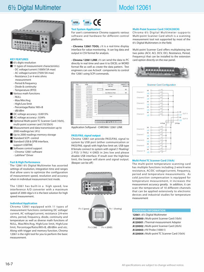
16-7 All specifications are subject to change without notice. All specifications are subject to change without notice.
12061 : 6½ Digital MultimeterA120000 : Multi-point Scanner Card (10ch)A120001 : Thermal-measurement AdapterA120002 : Multi-point Scanner Card (20ch)A120003 : HV Probe (1000:1)A120004 : Multi-point TC Scanner Card (10ch)
6½ Digital Multimeter Model 12061
KEY FEATURES 6½ digits resolution 11 types of measurement characteristics - DC voltage/current (1000V/3A max) - AC voltage/current (750V/3A max) - Resistance 2 or 4-wire ohms measurement - Period & frequency - Diode & continuity - Temperature (RTD) Various math functions - NULL - Max/Min/Avg - High/Low limit - Percentage/Ratio/ MX+B - dB/dBm DC voltage accuracy : 0.0015% AC voltage accuracy : 0.04% Optional Multi-point TC Scanner Card (10ch), multi-point scanner card (10/20ch) Measurement and data transmission up to 2000 readings/sec (4½) Up to 2000 readings memory storage Standard SCPI control Standard USB & GPIB interface, support USBTMC Software control support - Chroma 12061 software - LabView® Driver
Fast & High PerformanceThe 12061 6½ Digital Multimeter has assorted settings of resolution, integration time and ranges that allow users to optimize the configuration of measurement speed, resolution and accuracy when in individual measurement test mode.
The 12061 has bui l t-in a h igh speed, low interference A/D converter with a maximum speed of 2000 rdgs/s it is the best solution for high speed measurement.
Individual ApplicationChroma 12061 equipped with 11 t ypes of measurement functions containing DC voltage/current, AC voltage/current, resistance 2/4-wire ohms, period, frequency, diode, continuity and temperature as well as diverse math functions of NULL, Max/Min/Avg, High/Low limit, High/Low limit, Percentage/Ratio/MX+B, dB/dBm and etc. Along with trigger and memory function, Chroma 12061 is the right tool for you to perform the basic measurement.
Test System ApplicationFor user's convenience Chroma supports various software and hardware for different control platforms.
- Chroma 12061 TOOL : It is a real-time display interface for value monitoring. It can log data and output in CSV format for analysis.
- Chroma 12061 LINK : It can send the data to PC directly in real time and save it to EXCEL or WORD format file as well as create the data pattern. Test engineers can use ActiveX components to control the 12061 using SCPI commands.
PASS/FAIL signal outputChroma 12061 can provide PASS/FAIL signal to system by USB port (either communication or PASS/FAIL signal) with high/low limit set. USB type B female connect to system with signal (1 floating/ 2 PSS/ 3 FAIL/ 4 GND) in 2ms low and please disable USB interface. If result over the high/low limit, the beeper will alarm and signal output. (Beeper can be off )
Multi-Point Scanner Card (10CH/20CH)C h r o m a 6½ D i g i t a l M u l t i m e t e r s u p p o r t s Multi-point Scanner Card which is a scanning measurement tool not supported by most of the 6½ Digital Multimeters in the field.
Multi-point Scanner Card offers multiplexing ten two poles (ACV, ACI, DCV, DCI, Resistance, Period, Frequency) that can be installed to the extension card option directly on the rear panel.
HIChannel 1
Scanner Card Configuration
LOHI
Channel 2LO
HILOHILO
HIChannel 3
LOHI
Channel 4
OUT A
OUT B
LOHI
Channel 5
4-Pole 2-Pole
LO
HIChannel 6
LOHI
Channel 7LO
HIChannel 8
LOHI
Channel 9LOHI
Channel 10LO
ORDERING INFORMATION
Application Softpanel - CHROMA 12061 LINK
Multi-Point TC Scanner Card (10ch)The multi-point temperature scanning card has multiple functions including 2-wire/4-wire resistance, AC/DC voltage/current, frequency, period and temperature measurements. As cold junction compensation is equipped for temperature measurement, it increases the measurement accuracy greatly. In addition, it can scan the temperature of 10 different channels that can be applied extensively to electronic devices and industrial studies for temperature measurement
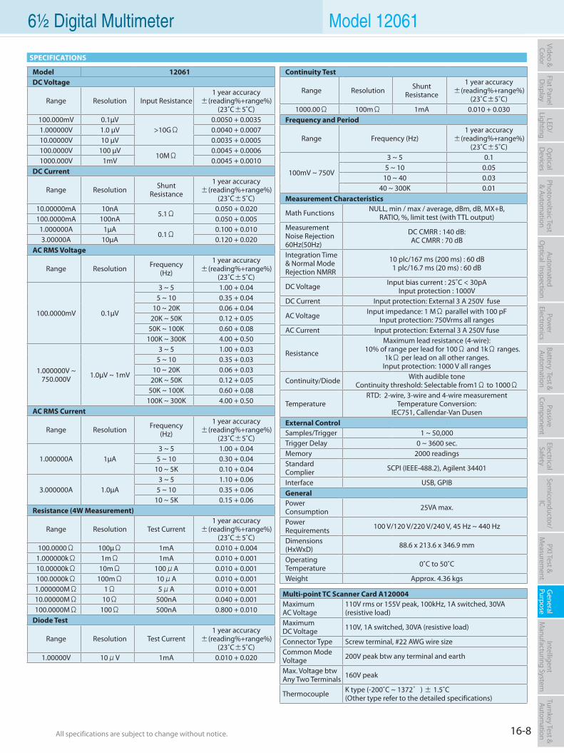
16-8All specifications are subject to change without notice. All specifications are subject to change without notice.
Flat PanelD
isplayPow
er Electronics
Electrical Safety
General
PurposePassive
Component
Semiconductor/
ICBattery Test & Autom
ationAutom
atedO
ptical Inspection Photovoltaic Test
& Automation
PXI Test &
Measurem
ent Intelligent
Manufacturing System
Video & Color
Turnkey Test & Autom
ation LED
/Lighting
Optical
Devices
6½ Digital Multimeter Model 12061
Model 12061DC Voltage
Range Resolution Input Resistance1 year accuracy
±(reading%+range%)(23˚C±5˚C)
100.000mV 0.1µV>10GΩ
0.0050 + 0.00351.000000V 1.0 µV 0.0040 + 0.000710.00000V 10 µV 0.0035 + 0.0005100.0000V 100 µV
10MΩ0.0045 + 0.0006
1000.000V 1mV 0.0045 + 0.0010DC Current
Range Resolution Shunt Resistance
1 year accuracy±(reading%+range%)
(23˚C±5˚C)10.00000mA 10nA
5.1Ω0.050 + 0.020
100.0000mA 100nA 0.050 + 0.0051.000000A 1µA
0.1Ω0.100 + 0.010
3.00000A 10µA 0.120 + 0.020AC RMS Voltage
Range Resolution Frequency(Hz)
1 year accuracy±(reading%+range%)
(23˚C±5˚C)
100.0000mV 0.1µV
3 ~ 5 1.00 + 0.045 ~ 10 0.35 + 0.04
10 ~ 20K 0.06 + 0.0420K ~ 50K 0.12 + 0.05
50K ~ 100K 0.60 + 0.08100K ~ 300K 4.00 + 0.50
1.000000V ~ 750.000V 1.0µV ~ 1mV
3 ~ 5 1.00 + 0.035 ~ 10 0.35 + 0.03
10 ~ 20K 0.06 + 0.0320K ~ 50K 0.12 + 0.05
50K ~ 100K 0.60 + 0.08100K ~ 300K 4.00 + 0.50
AC RMS Current
Range Resolution Frequency(Hz)
1 year accuracy±(reading%+range%)
(23˚C±5˚C)
1.000000A 1µA3 ~ 5 1.00 + 0.04
5 ~ 10 0.30 + 0.0410 ~ 5K 0.10 + 0.04
3.000000A 1.0µA3 ~ 5 1.10 + 0.06
5 ~ 10 0.35 + 0.0610 ~ 5K 0.15 + 0.06
Resistance (4W Measurement)
Range Resolution Test Current1 year accuracy
±(reading%+range%)(23˚C±5˚C)
100.0000Ω 100µΩ 1mA 0.010 + 0.0041.000000kΩ 1mΩ 1mA 0.010 + 0.00110.00000kΩ 10mΩ 100μA 0.010 + 0.001100.0000kΩ 100mΩ 10μA 0.010 + 0.0011.000000MΩ 1Ω 5μA 0.010 + 0.00110.00000MΩ 10Ω 500nA 0.040 + 0.001100.0000MΩ 100Ω 500nA 0.800 + 0.010
Diode Test
Range Resolution Test Current1 year accuracy
±(reading%+range%)(23˚C±5˚C)
1.00000V 10μV 1mA 0.010 + 0.020
Continuity Test
Range Resolution Shunt Resistance
1 year accuracy±(reading%+range%)
(23˚C±5˚C)1000.00Ω 100mΩ 1mA 0.010 + 0.030
Frequency and Period
Range Frequency (Hz)1 year accuracy
±(reading%+range%)(23˚C±5˚C)
100mV ~ 750V
3 ~ 5 0.15 ~ 10 0.05
10 ~ 40 0.0340 ~ 300K 0.01
Measurement Characteristics
Math Functions NULL, min / max / average, dBm, dB, MX+B, RATIO, %, limit test (with TTL output)
Measurement Noise Rejection 60Hz(50Hz)
DC CMRR : 140 dB:AC CMRR : 70 dB
Integration Time & Normal Mode Rejection NMRR
10 plc/167 ms (200 ms) : 60 dB1 plc/16.7 ms (20 ms) : 60 dB
DC Voltage Input bias current : 25˚C < 30pAInput protection : 1000V
DC Current Input protection: External 3 A 250V fuse
AC Voltage Input impedance: 1 MΩ parallel with 100 pFInput protection: 750Vrms all ranges
AC Current Input protection: External 3 A 250V fuse
Resistance
Maximum lead resistance (4-wire): 10% of range per lead for 100Ω and 1kΩ ranges.
1kΩ per lead on all other ranges. Input protection: 1000 V all ranges
Continuity/Diode With audible toneContinuity threshold: Selectable from1Ω to 1000Ω
TemperatureRTD: 2-wire, 3-wire and 4-wire measurement
Temperature Conversion: IEC751, Callendar-Van Dusen
External ControlSamples/Trigger 1 ~ 50,000Trigger Delay 0 ~ 3600 sec.Memory 2000 readingsStandard Complier SCPI (IEEE-488.2), Agilent 34401
Interface USB, GPIBGeneralPower Consumption 25VA max.
Power Requirements 100 V/120 V/220 V/240 V, 45 Hz ~ 440 Hz
Dimensions (HxWxD) 88.6 x 213.6 x 346.9 mm
Operating Temperature 0˚C to 50˚C
Weight Approx. 4.36 kgs
SPECIFICATIONS
Multi-point TC Scanner Card A120004MaximumAC Voltage
110V rms or 155V peak, 100kHz, 1A switched, 30VA (resistive load)
MaximumDC Voltage 110V, 1A switched, 30VA (resistive load)
Connector Type Screw terminal, #22 AWG wire sizeCommon Mode Voltage 200V peak btw any terminal and earth
Max. Voltage btw Any Two Terminals 160V peak
Thermocouple K type (-200˚C ~ 1372°) ± 1.5˚C(Other type refer to the detailed specifications)
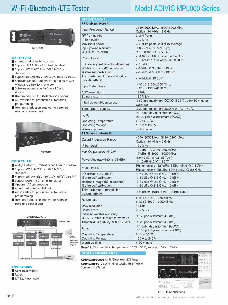
16-9 All specifications are subject to change without notice. All specifications are subject to change without notice.
Wi-Fi /Bluetooth /LTE Tester Model ADIVIC MP5000 Series
KEY FEATURES 4-port, parallel, high speed test Supports FDD LTE cellular test standard Supports Wi-Fi 802.11ac, 802.11a/b/g/n standards Supports Bluetooth V1.x/V2.x/V3.x EDR/V4.x BLE Software Defined Radio(SDR) architecture with Wideband VSG/VSA in one box Software upgradable for future RF test standards User friendly GUI for R&D/QA applications API available for production automation programming Turn-key production automation software support upon request
ADIVIC MP5000 : Wi-Fi /Bluetooth /LTE TesterADIVIC MP5010 : Wi-Fi /Bluetooth / GPS Mobile Connectivity Tester
Note *1 : Test condition Temperature : 15 ~ 35, Voltage : 100 V to 240 V
ORDERING INFORMATION
SPECIFICATIONSRF Analyzer (Note *1)
Input Frequency Range2150~2600 MHz, 4900~6000 MHzOption : 10 MHz ~ 6 GHz
RF Port number 2 or 4 PortsIF bandwidth 120 MHzMax input power +30 dBm peak, +20 dBm averageInput power accuracy @(+20 to -75 dBm)
±0.75 dB (±0.5 dB Typ)±1.0 dB@ 0 ~ 50
Phase Noise< -100dBc: 1 KHz offset @2.4 GHz< -9 5dBc: 1 KHz offset @5.8 GHz
LO Leakage (after self-c alibration) <-50 dBcsideband image (IQ-imbalance)@after self-calibration
<-50dBc @ 2.4GHz, -10dBm<-50dBc @ 5.8GHz, -10dBm
Third order input inter-modulationdistortion(IMD3)
< -70dBc@-10 dBm
Input Return loss> 10 dB 2150~2600 MH z> 12 dB 4900~6000 MH z
ADC resolution 16 BitsSample rate 160 MS/s
Initial achievable accuracy±50 ppb maximum (OCXO)@25 , after 60 minutes warm up
Temperature stability ±20 ppb maximum(OCXO) @0 ~ 50
Aging±1 ppb / day maximum (OCXO)±100 ppb / yr maximum (OCXO)
Operating Temperature 0 to 50 Operating Voltage 100 V to 240 VWarm - up time > 30 minuteRF Generator (Note *1)
Output Frequency Range4900~6000 MHz , 2150~2600 MHzOption : 10 MHz ~ 6 GHz
IF bandwidth 120 MHz
Max Output power@ CW+10 dBm @ 2150~2600 MHz+7 dBm @ 4900 ~ 6000 MHz
Power Accuracy@(0 to -95 dBm)±0.75 dB (± 0.5 dB Typ )±1.0 dB @ 0 ~ 50
Phase NoisePhase noise < -100 dBc: 1 KHz offset @ 2.4 GHzPhase noise < -95 dBc: 1 KHz offset @ 5.8 GHz
LO leakage(DC offset) @after self-calibration
< -50 dBc @ 2.4 GHz, -10 dB m< -50 dBc @ 5.8 GHz, -10 dB m
sideband image (IQ-imbalance)@after self-calibration
< -50 dBc @ 2.4 GHz, -10 dB m< -50 dBc @ 5.8 GHz, -10 dB m
Third order inter -modulationdistortion(IMD3)
<-60dBc@-10dBm(two -13dBm Tone)
Return loss> 10 dB 2150 ~ 2600 M Hz> 12 dB 4900 ~ 6000 M Hz
DAC resolution 16 BitsSample rate 960 MS/sInitial achievable accuracy@ 25 , after 60 minutes warm up
± 50 ppb maximum (OCXO)
Temperature stability @ 0 ~ 50 ± 20 ppb maximum (OCXO)
Aging±1 ppb / day maximum (OCXO)±100 ppb / yr maximum (OCXO)
Operating Temperature 0 to 50 Operating Voltage 100 V to 240 VWarm-up time > 30 minute
MP5000
R&D, QA applications
KEY FEATURES Wi-Fi, Bluetooth, GPS test capabilities in one box Supports Wi-Fi 802.11ac, 802.11a/b/g/n standards Supports Bluetooth V1.x/V2.x/V3.x EDR/V4.x BLE Supports GPS 1-8 Channel simulator Optional LTE test package 4-port multi-site parallel test API available for production automation programming Turn-key production automation software support upon request
APPLICATIONS Consumer Mobile Tablet IoT (i.e. Automotive)
MP5010
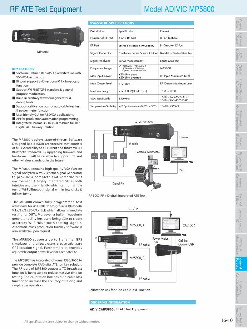
16-10All specifications are subject to change without notice. All specifications are subject to change without notice.
Flat PanelD
isplayPow
er Electronics
Electrical Safety
General
PurposePassive
Component
Semiconductor/
ICBattery Test & Autom
ationAutom
atedO
ptical Inspection Photovoltaic Test
& Automation
PXI Test &
Measurem
ent Intelligent
Manufacturing System
Video & Color
Turnkey Test & Autom
ation LED
/Lighting
Optical
Devices
RF ATE Test Equipment Model ADIVIC MP5800
VSA/VSG RF SPECIFICATIONS
ADIVIC MP5800 : RF ATE Test Equipment
ORDERING INFORMATION
MP5800
RF SOC (RF + Digital) Integrated ATE Test
Calibration Box for Auto Cable loss Function
KEY FEATURES Software Defined Radio(SDR) architecture with VSG/VSA in one Box RF port support Bi-Directional & TX broadcast function Support Wi-Fi/BT/GPS standard & general purpose modulation Build-in arbitrary waveform generator & debug tools Support calibration box for auto cable loss test & power meter function User friendly GUI for R&D/QA applications API for production automation programming Integrated Chroma 3380/3650 to build full RF/ Digital ATE turnkey solution
The MP5800 deploys state-of-the-art Software Designed Radio (SDR) architecture that consists of full extendibility to all current and future Wi-Fi /Bluetooth standards. By upgrading firmware and hardware, it will be capable to support LTE and other wireless standards in the future.
The MP5800 contains high quality VSA (Vector Signal Analyzer) & VSG (Vector Signal Generator) to p rov i d e a co m p l e te a n d ve r s a t i l e te s t environment. A highly integrated GUI is both intuitive and user-friendly which can run simple test of Wi-Fi/Bluetooth signal within few clicks & full test items.
The MP5800 comes ful ly programmed test waveforms for Wi-Fi 802.11a/b/g/n/ac & Bluetooth V.1.x/2.x/3.xEDR/4.x BLE which allows immediate testing for DUTs. Moreover, a built-in waveform generator utility lets users being able to create a r b i t ra r y Wi-Fi/B l u e to o t h te s t i n g s i gn a l s. Automatic mass production turnkey software is also available upon request.
The MP5800 suppor ts up to 8 channel GPS simulator and allows users create arbitrary GPS location signal. Furthermore, it provides adjustable output power level for each satellite.
The MP5800 has integrated Chroma 3380/3650 to provide complete RF/Digital ATE turnkey solution. The RF port of MP5800 supports TX broadcast function is being able to reduce massive time on testing. The calibration box has auto cable loss function to increase the accuracy of testing and simplify the operation.
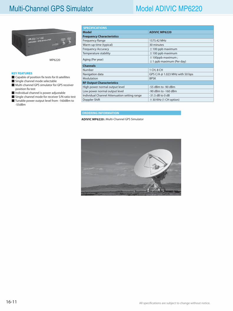
16-11 All specifications are subject to change without notice. All specifications are subject to change without notice.
Multi-Channel GPS Simulator Model ADIVIC MP6220
KEY FEATURES Capable of position fix tests for 8 satellites Single channel mode selectable Multi-channel GPS simulator for GPS receiver position fix test Individual channel is power adjustable Single channel mode for receiver S/N ratio test Tunable power output level from -160dBm to -55dBm
ADIVIC MP6220 : Multi-Channel GPS Simulator
ORDERING INFORMATION
MP6220
SPECIFICATIONSModel ADIVIC MP6220Frequency CharacteristicsFrequency Range 1575.42 MHzWarm-up time (typical) 30 minutesFrequency Accuracy ±100 ppb maximumTemperature stability ±100 ppb maximum
Aging (Per year) ±100ppb maximum ; ±1 ppb maximum (Per day)
ChannelsNumber 1 CH, 8 CHNavigation data GPS C/A @ 1.023 MHz with 50 bpsModulation BPSKRF Output CharacteristicsHigh power normal output level -55 dBm to -90 dBmLow power normal output level -90 dBm to -160 dBmIndividual Channel Attenuation setting range -31.5 dB to 0 dBDoppler Shift ±30 KHz (1 CH option)
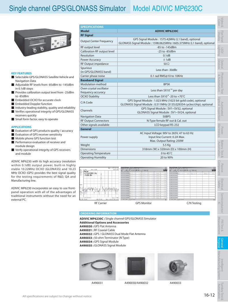
16-12All specifications are subject to change without notice. All specifications are subject to change without notice.
Flat PanelD
isplayPow
er Electronics
Electrical Safety
General
PurposePassive
Component
Semiconductor/
ICBattery Test & Autom
ationAutom
atedO
ptical Inspection Photovoltaic Test
& Automation
PXI Test &
Measurem
ent Intelligent
Manufacturing System
Video & Color
Turnkey Test & Autom
ation LED
/Lighting
Optical
Devices
Single channel GPS/GLONASS Simulator Model ADIVIC MP6230C
KEY FEATURES Selectable GPS/GLONASS Satellite Vehicle and
Navigation Data Adjustable RF levels from -85dBm to -145dBm
in 0.1dB steps Provides calibration output level from -25dBm
to -85dBm Embedded OCXO for accurate clock Embedded Doppler function Industry-leading stability, quality and reliability Verifies operational integrity of GPS/GLONASS
receivers quickly Small form factor, easy to operate
APPLICATIONS Evaluation of GPS products quality / accuracy Evaluation of GPS receiver sensitivity Mobile phone GPS function test Performance evaluation of receiver and
module design Verify operational integrity of GPS receivers and module
ADIVIC MP6230 with its high accuracy (resolution within 0.1dB) output power, built-in highly stable 10.22MHz OCXO (GLONASS) and 10.23 MHz OCXO (GPS) provides the best signal quality for the testing requirements of R&D, QA and Manufacturing line.
ADIVIC MP6230 incorporates an easy to use front-panel operation with all of the advantages of traditional instruments without the need for an external PC.
ADIVIC MP6230C : Single channel GPS/GLONASS SimulatorAdditional Options and Accessories A490030 : GPS Flat AntennaA490031 : RF Coaxial CableA490032 : GPS / GLONASS Dual Mode Flat AntennaA490033 : 50 ohm Terminator (N Type)A490034 : GPS Signal Module A490035 : GLONASS Signal Module
ORDERING INFORMATION
A490031 A490030/A490032 A490033
SPECIFICATIONSModel ADIVIC MP6230CRF Signal
Output Center FrequencyGPS Signal Module : 1575.42MHz (L1 band), optional
GLONASS Signal Module : 1598.0625MHz-1605.375MHz (L1 band), optional RF output level -85 to -145dBmCalibration RF output level -25 to -85dBmResolution 0.1dBPower Accuracy ±1dBRF Output impedance 50ΩSpurious(in GPS/GLONASS band)
Less than -30dBc
Carrier phase noise 0.1 rad RMS@10 to 10KHzBaseband SignalModulation method BPSKOven crystal oscillatorfrequency accuracy
Less than 5X10⁻¹⁰ per day
OCXO Stability Less than 5X10⁻⁹ -20 to +70˚C
C/A CodeGPS Signal Module : 1.023 MHz (1023 bit gold code), optional
GLONASS Signal Module : 0.511MHz (3135.029354 cycles/chip), optional
Channels GPS Signal Module : SV1~SV32, optional
GLONASS Signal Module : SV1~SV24, optional Navigation Data 50BPSRF Output Connectors N-Type female RF out & Cal. outOther signals available LCD keypad RS-232General
Power supplyAC Input Voltage: 90V to 265V, 47 to 63 Hz
Input line Current: 0.2A Max.Max. Output Rating: 250W
Weight 5.5 KgDimensions 318mm (W) x 320mm (D) x 100mm (H)Operating Temperature 0 to 45˚COperating Humidity 20 to 90%
RF Carrier GPS Monitor C/N Testing
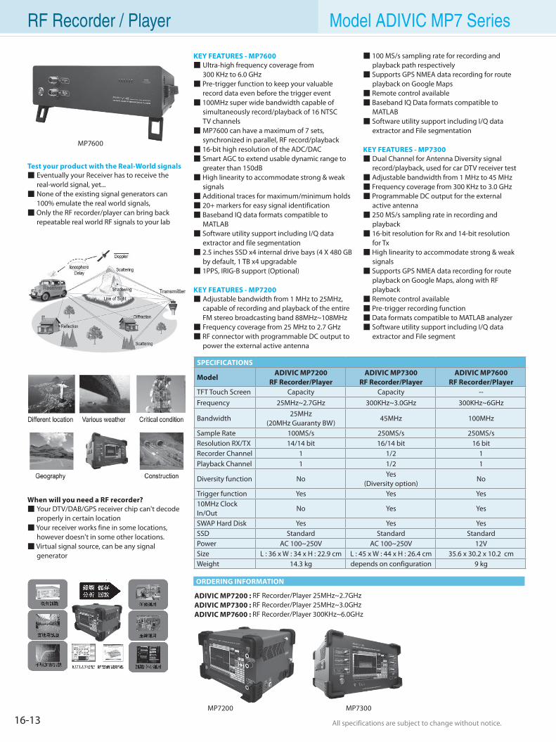
16-13 All specifications are subject to change without notice. All specifications are subject to change without notice.
RF Recorder / Player Model ADIVIC MP7 Series
ADIVIC MP7200 : RF Recorder/Player 25MHz~2.7GHzADIVIC MP7300 : RF Recorder/Player 25MHz~3.0GHzADIVIC MP7600 : RF Recorder/Player 300KHz~6.0GHz
Test your product with the Real-World signals Eventually your Receiver has to receive the real-world signal, yet... None of the existing signal generators can 100% emulate the real world signals, Only the RF recorder/player can bring back repeatable real world RF signals to your lab
When will you need a RF recorder? Your DTV/DAB/GPS receiver chip can't decode properly in certain location Your receiver works fine in some locations, however doesn't in some other locations. Virtual signal source, can be any signal generator
MP7600
ORDERING INFORMATION
KEY FEATURES - MP7600 Ultra-high frequency coverage from 300 KHz to 6.0 GHz Pre-trigger function to keep your valuable record data even before the trigger event 100MHz super wide bandwidth capable of simultaneously record/playback of 16 NTSC TV channels MP7600 can have a maximum of 7 sets, synchronized in parallel, RF record/playback 16-bit high resolution of the ADC/DAC Smart AGC to extend usable dynamic range to greater than 150dB High linearity to accommodate strong & weak signals Additional traces for maximum/minimum holds 20+ markers for easy signal identification Baseband IQ data formats compatible to MATLAB Software utility support including I/Q data extractor and file segmentation 2.5 inches SSD x4 internal drive bays (4 X 480 GB by default, 1 TB x4 upgradable 1PPS, IRIG-B support (Optional)
KEY FEATURES - MP7200 Adjustable bandwidth from 1 MHz to 25MHz, capable of recording and playback of the entire FM stereo broadcasting band 88MHz~108MHz Frequency coverage from 25 MHz to 2.7 GHz RF connector with programmable DC output to power the external active antenna
100 MS/s sampling rate for recording and playback path respectively Supports GPS NMEA data recording for route playback on Google Maps Remote control available Baseband IQ Data formats compatible to MATLAB Software utility support including I/Q data extractor and File segmentation
KEY FEATURES - MP7300 Dual Channel for Antenna Diversity signal record/playback, used for car DTV receiver test Adjustable bandwidth from 1 MHz to 45 MHz Frequency coverage from 300 KHz to 3.0 GHz Programmable DC output for the external active antenna 250 MS/s sampling rate in recording and playback 16-bit resolution for Rx and 14-bit resolution for Tx High linearity to accommodate strong & weak signals Supports GPS NMEA data recording for route playback on Google Maps, along with RF playback Remote control available Pre-trigger recording function Data formats compatible to MATLAB analyzer Software utility support including I/Q data extractor and File segment
MP7300MP7200
SPECIFICATIONS
Model ADIVIC MP7200
RF Recorder/PlayerADIVIC MP7300
RF Recorder/PlayerADIVIC MP7600
RF Recorder/PlayerTFT Touch Screen Capacity Capacity --Frequency 25MHz~2.7GHz 300KHz~3.0GHz 300KHz~6GHz
Bandwidth25MHz
(20MHz Guaranty BW)45MHz 100MHz
Sample Rate 100MS/s 250MS/s 250MS/sResolution RX/TX 14/14 bit 16/14 bit 16 bit Recorder Channel 1 1/2 1 Playback Channel 1 1/2 1
Diversity function No Yes
(Diversity option)No
Trigger function Yes Yes Yes 10MHz ClockIn/Out
No Yes Yes
SWAP Hard Disk Yes Yes Yes SSD Standard Standard StandardPower AC 100~250V AC 100~250V 12VSize L : 36 x W : 34 x H : 22.9 cm L : 45 x W : 44 x H : 26.4 cm 35.6 x 30.2 x 10.2 cmWeight 14.3 kg depends on configuration 9 kg
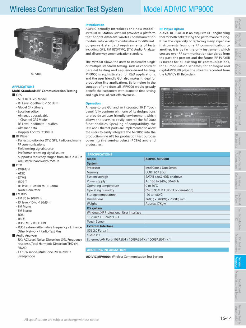
16-14All specifications are subject to change without notice. All specifications are subject to change without notice.
Flat PanelD
isplayPow
er Electronics
Electrical Safety
General
PurposePassive
Component
Semiconductor/
ICBattery Test & Autom
ationAutom
atedO
ptical Inspection Photovoltaic Test
& Automation
PXI Test &
Measurem
ent Intelligent
Manufacturing System
Video & Color
Turnkey Test & Autom
ation LED
/Lighting
Optical
Devices
Wireless Communication Test System Model ADIVIC MP9000
APPLICATIONSMulti-Standards RF Communication Testing GPS - 6CH, 8CH GPS Model - RF Level -55dBm to -160 dBm - Global City Library - Location editor - Almanac upgradeable - 1 Channel GPS Model - RF Level -55dBm to -160dBm - Almanac data - Doppler Control ±30KHz RF Player - Perfect solution for DTV, GPS, Radio and many RF communications - Field testing signal source - Performance testing signal source - Supports Frequency ranged from 300K-2.7GHz - Adjustable bandwidth 25MHz DTV - DVB-T/H - ATSC - DTMB - ISDB-T - RF level +10dBm to -110dBm - Noise Generator FM RDS - FM 76 to 108MHz - RF level -10 to -120dBm - FM Mono - FM Stereo - RDS - RBDS - RDS TMC / RBDS TMC - RDS Feature - Alternative Frequency / Enhance Other Network / Radio Text Plus Audio Analyzer - RX : AC Level, Noise, Distortion, S/N, Frequency response, Total Harmonic Distortion THD+N, SINAD - TX : CW mode, Multi Tone, 20Hz-20KHz Sweepmode ADIVIC MP9000 : Wireless Communication Test System
ORDERING INFORMATION
IntroductionADIVIC proudly introduces the new model - MP9000 RF Station. MP9000 provides a platform that adopts different wireless communication modules into variety of combinations for differentpurposes & standard require-ments of tests including GPS, FM RDS/TMC, DTV, Audio Analyzer and all one way communication standard.
The MP9000 allows the users to implement single or multiple standards testing, such as concurrent paral-lel testing and sequence-based testing. MP9000 is sophisticated for R&D applications, and the user friendly GUI also makes it ideal for production line applications. By bringing in the concept of one does all, MP9000 would greatly benefit the customers with dramatic time saving and high-level of cost-effectiveness.
OperationAn easy-to use GUI and an integrated 10.2" Touch panel fully conform with one of its designations to provide an user-friendly environment which allows the users to easily control the MP9000 functionalities. Speaking of compatibility, the USB and Ethernet ports are implemented to allow the users to easily integrate the MP9000 into the production-line ATE for production test purpose covering the semi-product (PCBA) and end product test.
RF Player OptionADIVIC RF PLAYER is an exquisite RF- engineering tool for both field testing and performance testing. It has the capability of replacing many expensive instruments from one RF communication to another. It is by far the only instrument which crosses over RF communication standards from the past, the present and the future. RF PLAYER is meant for all existing RF communications, for all modulation schemes, for analogue and digital.MP9000 plays the streams recorded from the ADIVIC's RF Recorders.
SPECIFICATIONSModel ADIVIC MP9000System Processor Intel Core 2 Duo SeriesMemory DDRII 667 2GBSystem storage SATAII 320G HDD or abovePower supply AC 100 to 240V, 50/60HzOperating temperature 0 to 50Operating humidity 0% to 95% RH (Non Condensation)Storage temperature -20 to +80Dimensions 360(L) x 340(W) x 200(H) mmWeight Approx.17KgwOS systemWindows XP Professional User interface10.2 inch TFT color LCDTouch ScreenExternal InterfaceUSB 2.0 Port x 4eSATA x 1Ethernet LAN Port (10BASE-T / 100BASE-TX / 1000BASE-T) x 1
MP9000

Intelligent Manufacturing System (IMS) Solution
Manufacturing Execution System (MES) 17-1Hemodialysis Management System (HDMS) 17-3Fast Easy Player 17-4
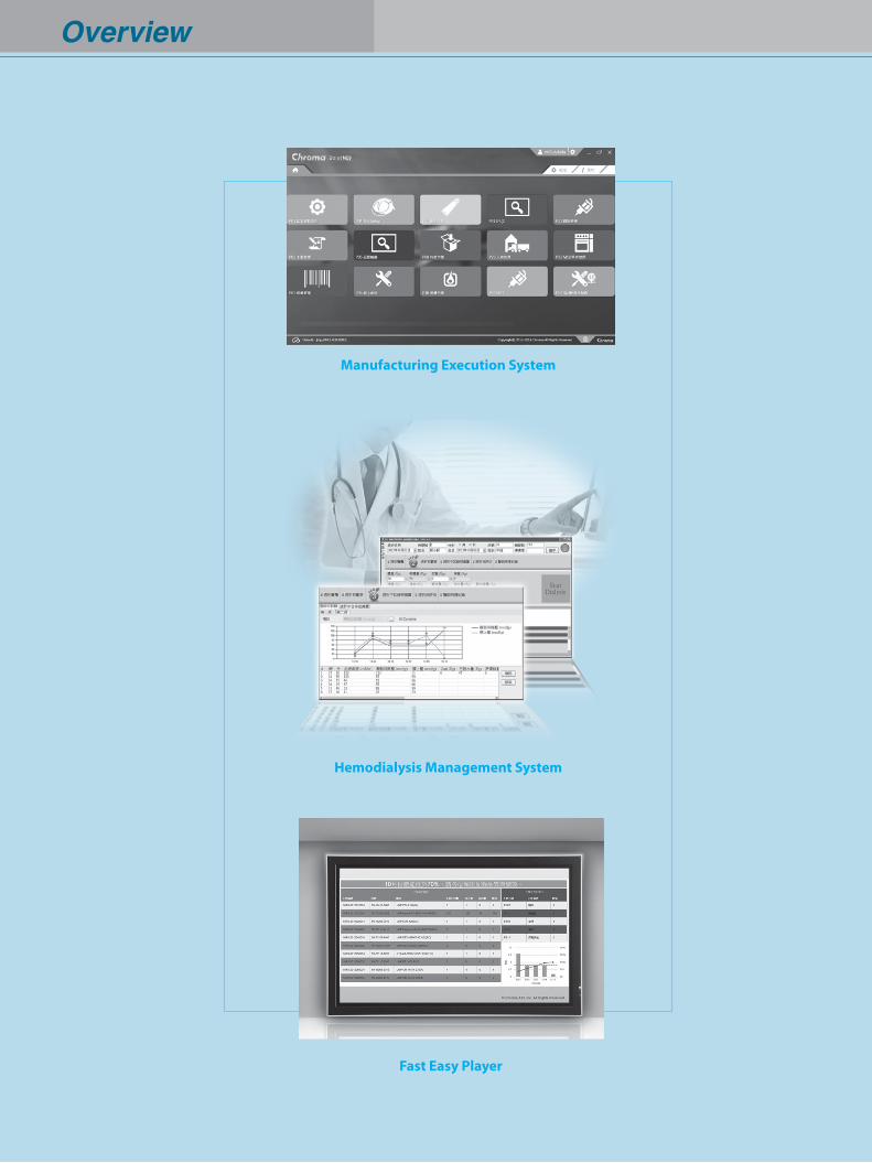
Overview
Manufacturing Execution System
Hemodialysis Management System
Fast Easy Player
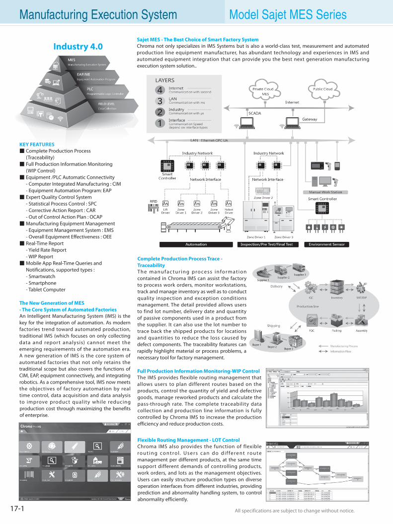
17-1 All specifications are subject to change without notice. All specifications are subject to change without notice.
Manufacturing Execution System Model Sajet MES Series
Complete Production Process Trace - TraceabilityTh e m a n u f a c t u r i n g p ro ce s s i n fo r m a t i o n contained in Chroma IMS can assist the factory to process work orders, monitor workstations, track and manage inventory as well as to conduct quality inspection and exception conditions management. The detail provided allows users to find lot number, delivery date and quantity of passive components used in a product from the supplier. It can also use the lot number to trace back the shipped products for locations and quantities to reduce the loss caused by defect components. The traceability features can rapidly highlight material or process problems, a necessary tool for factory management.
Full Production Information Monitoring-WIP ControlThe IMS provides flexible routing management that allows users to plan different routes based on the products, control the quantity of yield and defective goods, manage reworked products and calculate the pass-through rate. The complete traceability data collection and production line information is fully controlled by Chroma IMS to increase the production efficiency and reduce production costs.
Flexible Routing Management - LOT ControlChroma IMS also provides the function of flexible ro u t i n g c o n t ro l. U s e r s c a n d o d i f fe re n t ro u t e management per different products, at the same time support different demands of controlling products, work orders, and lots as the management objectives. Users can easily structure production types on diverse operation interfaces from different industries, providing prediction and abnormality handling system, to control abnormality efficiently.
KEY FEATURES Complete Production Process (Traceability) Full Production Information Monitoring (WIP Control) Equipment /PLC Automatic Connectivity - Computer Integrated Manufacturing : CIM - Equipment Automation Program: EAP Expert Quality Control System - Statistical Process Control : SPC - Corrective Action Report : CAR - Out of Control Action Plan : OCAP Manufacturing Equipment Management - Equipment Management System : EMS - Overall Equipment Effectiveness : OEE Real-Time Report - Yield Rate Report - WIP Report Mobile App Real-Time Queries and
Notifications, supported types : - Smartwatch - Smartphone - Tablet Computer
The New Generation of MES- The Core System of Automated FactoriesAn Intelligent Manufacturing System (IMS) is the key for the integration of automation. As modern factories trend toward automated production, traditional IMS (which focuses on only collecting data and repor t analysis) cannot meet the emerging requirements of the automation era. A new generation of IMS is the core system of automated factories that not only retains the traditional scope but also covers the functions of CIM, EAP, equipment connectively, and integrating robotics. As a comprehensive tool, IMS now meets the objectives of factory automation by real time control, data acquisition and data analysis to improve product quality while reducing production cost through maximizing the benefits of enterprise.
Sajet MES - The Best Choice of Smart Factory SystemChroma not only specializes in IMS Systems but is also a world-class test, measurement and automated production line equipment manufacturer, has abundant technology and experiences in IMS and automated equipment integration that can provide you the best next generation manufacturing execution system solution..
Industry 4.0
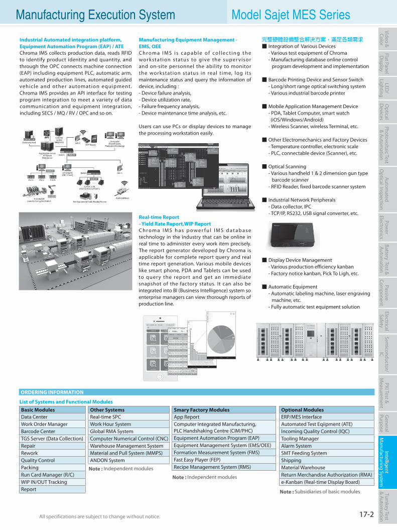
17-2All specifications are subject to change without notice. All specifications are subject to change without notice.
Flat PanelD
isplayPow
er Electronics
Electrical Safety
General
PurposePassive
Component
Semiconductor/
ICBattery Test & Autom
ationAutom
atedO
ptical Inspection Photovoltaic Test
& Automation
PXI Test &
Measurem
ent Intelligent
Manufacturing System
Video & Color
Turnkey Test & Autom
ation LED
/Lighting
Optical
Devices
Industrial Automated integration platform,Equipment Automation Program (EAP) / ATEChroma IMS collects production data, reads RFID to identify product identity and quantity, and through the OPC connects machine connection (EAP) including equipment PLC, automatic arm, automated production lines, automated guided vehicle and other automation equipment. Chroma IMS provides an API interface for testing program integration to meet a variety of data communication and equipment integration, including SECS / MQ / RV / OPC and so on.
Manufacturing Equipment Management -EMS, OEEC h ro m a I M S i s c a p a b l e o f c o l l e c t i n g t h e workstat ion status to give the super visor and on-site personnel the ability to monitor the workstation status in real t ime, log its maintenance status and query the information of device, including :- Device failure analysis,- Device utilization rate,- Failure frequency analysis,- Device maintenance time analysis, etc.
Users can use PCs or display devices to manage the processing workstation easily.
Real-time Report - Yield Rate Report,WIP ReportC h r o m a I M S h a s p o w e r f u l I M S d a t a b a s e technology in the industry that can be online in real time to administer every work item precisely. The report generator developed by Chroma is applicable for complete report query and real time report generation. Various mobile devices like smart phone, PDA and Tablets can be used to quer y the repor t and get an immediate snapshot of the factory status. It can also be integrated into BI (Business Intelligence) system so enterprise managers can view thorough reports of production line.
List of Systems and Functional Modules
ORDERING INFORMATION
Manufacturing Execution System Model Sajet MES Series
Note : Subsidiaries of basic modules
Note : Independent modules
Note : Independent modules
Basic ModulesData CenterWork Order ManagerBarcode CenterTGS Server (Data Collection)RepairReworkQuality ControlPackingRun Card Manager (R/C)WIP IN/OUT TrackingReport
Other SystemsReal-time SPCWork Hour SystemGlobal RMA SystemComputer Numerical Control (CNC)Warehouse Management SystemMaterial and Pull System (MMPS)ANDON System
Smary Factory ModulesApp ReportComputer Integrated Manufacturing,PLC Handshaking Centre (CIM/PHC)Equipment Automation Program (EAP)Equipment Management System (EMS/OEE)Formation Measurement System (FMS)Fast Easy Player (FEP)Recipe Management System (RMS)
Optional ModulesERP/MES InterfaceAutomated Test Eqiipment (ATE)Incoming Quality Control (IQC)Tooling ManagerAlarm SystemSMT Feeding SystemShippingMaterial WarehouseReturn Merchandise Authorization (RMA)e-Kanban (Real-time Display Board)
完整硬體設備整合解決方案,滿足各類需求 Integration of Various Devices - Various test equipment of Chroma - Manufacturing database online control program development and implementation
Barcode Printing Device and Sensor Switch - Long/short range optical switching system - Various industrial barcode printer
Mobile Application Management Device - PDA, Tablet Computer, smart watch (iOS/Windows/Android) - Wireless Scanner, wireless Terminal, etc.
Other Electromechanics and Factory Devices - Temperature controller, electronic scale - PLC, connectable device (Scanner), etc.
Optical Scanning - Various handheld 1 & 2 dimension gun type barcode scanner - RFID Reader, fixed barcode scanner system
Industrial Network Peripherals - Data collector, IPC - TCP/IP, RS232, USB signal converter, etc.
Display Device Management - Various production efficiency kanban - Factory notice kanban, Pick To Ligh, etc.
Automatic Equipment - Automatic labeling machine, laser engraving machine, etc. - Fully automatic test equipment solution
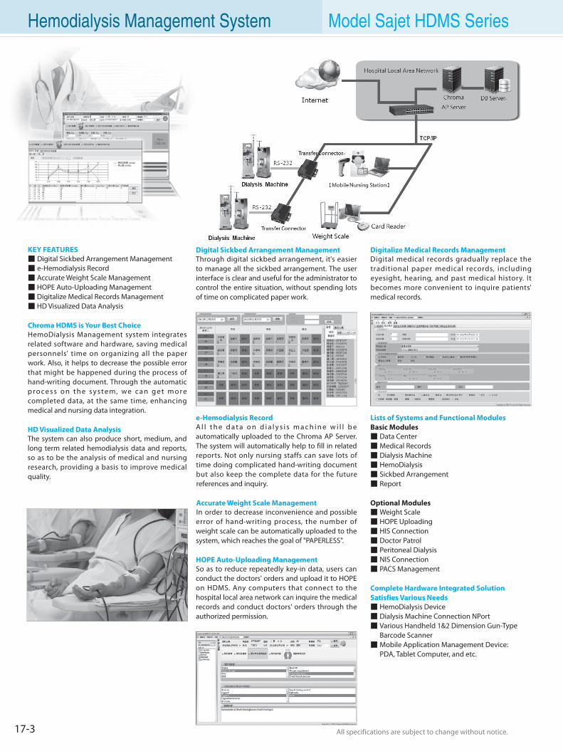
17-3 All specifications are subject to change without notice. All specifications are subject to change without notice.
Hemodialysis Management System Model Sajet HDMS Series
KEY FEATURES Digital Sickbed Arrangement Management e-Hemodialysis Record Accurate Weight Scale Management HOPE Auto-Uploading Management Digitalize Medical Records Management HD Visualized Data Analysis
Chroma HDMS is Your Best ChoiceHemoDialysis Management system integrates related software and hardware, saving medical personnels' time on organizing all the paper work. Also, it helps to decrease the possible error that might be happened during the process of hand-writing document. Through the automatic p ro c e s s o n t h e s y s t e m, we c a n g e t m o re completed data, at the same time, enhancing medical and nursing data integration.
HD Visualized Data Analysis The system can also produce short, medium, and long term related hemodialysis data and reports, so as to be the analysis of medical and nursing research, providing a basis to improve medical quality.
Digital Sickbed Arrangement ManagementThrough digital sickbed arrangement, it's easier to manage all the sickbed arrangement. The user interface is clear and useful for the administrator to control the entire situation, without spending lots of time on complicated paper work.
e-Hemodialysis RecordA l l t h e d a t a o n d i a l y s i s m a c h i n e w i l l b e automatically uploaded to the Chroma AP Server. The system will automatically help to fill in related reports. Not only nursing staffs can save lots of time doing complicated hand-writing document but also keep the complete data for the future references and inquiry.
Accurate Weight Scale ManagementIn order to decrease inconvenience and possible error of hand-writing process, the number of weight scale can be automatically uploaded to the system, which reaches the goal of "PAPERLESS".
HOPE Auto-Uploading ManagementSo as to reduce repeatedly key-in data, users can conduct the doctors' orders and upload it to HOPE on HDMS. Any computers that connect to the hospital local area network can inquire the medical records and conduct doctors' orders through the authorized permission.
Digitalize Medical Records ManagementDigital medical records gradually replace the traditional paper medical records, including eyesight, hearing, and past medical history. It becomes more convenient to inquire patients' medical records.
Lists of Systems and Functional ModulesBasic Modules Data Center Medical Records Dialysis Machine HemoDialysis Sickbed Arrangement Report
Optional Modules Weight Scale HOPE Uploading HIS Connection Doctor Patrol Peritoneal Dialysis NIS Connection PACS Management
Complete Hardware Integrated Solution Satisfies Various Needs HemoDialysis Device Dialysis Machine Connection NPort Various Handheld 1&2 Dimension Gun-Type
Barcode Scanner Mobile Application Management Device: PDA, Tablet Computer, and etc.
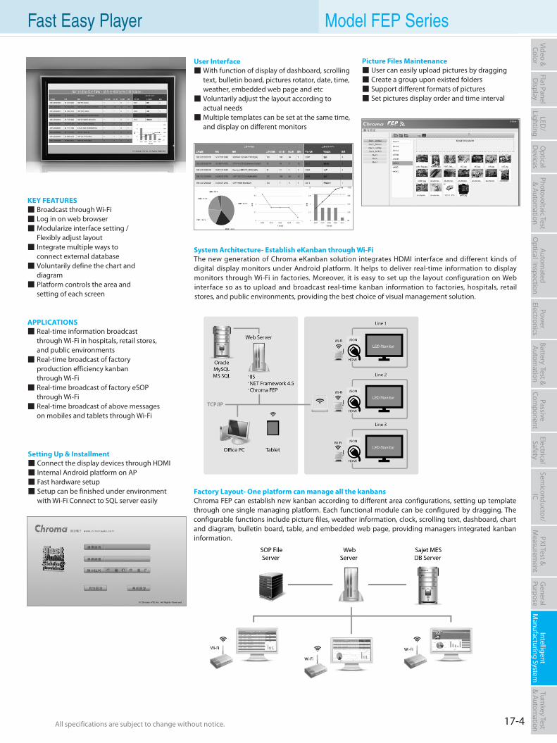
17-4All specifications are subject to change without notice. All specifications are subject to change without notice.
Flat PanelD
isplayPow
er Electronics
Electrical Safety
General
PurposePassive
Component
Semiconductor/
ICBattery Test & Autom
ationAutom
atedO
ptical Inspection Photovoltaic Test
& Automation
PXI Test &
Measurem
ent Intelligent
Manufacturing System
Video & Color
Turnkey Test & Autom
ation LED
/Lighting
Optical
Devices
Fast Easy Player Model FEP Series
Setting Up & Installment Connect the display devices through HDMI Internal Android platform on AP Fast hardware setup Setup can be finished under environment with Wi-Fi Connect to SQL server easily
Picture Files Maintenance User can easily upload pictures by dragging Create a group upon existed folders Support different formats of pictures Set pictures display order and time interval
KEY FEATURES Broadcast through Wi-Fi Log in on web browser Modularize interface setting / Flexibly adjust layout Integrate multiple ways to connect external database Voluntarily define the chart and diagram Platform controls the area and setting of each screen
APPLICATIONS Real-time information broadcast through Wi-Fi in hospitals, retail stores, and public environments Real-time broadcast of factory production efficiency kanban through Wi-Fi Real-time broadcast of factory eSOP through Wi-Fi Real-time broadcast of above messages on mobiles and tablets through Wi-Fi
User Interface With function of display of dashboard, scrolling text, bulletin board, pictures rotator, date, time, weather, embedded web page and etc Voluntarily adjust the layout according to actual needs Multiple templates can be set at the same time, and display on different monitors
System Architecture- Establish eKanban through Wi-FiThe new generation of Chroma eKanban solution integrates HDMI interface and different kinds of digital display monitors under Android platform. It helps to deliver real-time information to display monitors through Wi-Fi in factories. Moreover, it is easy to set up the layout configuration on Web interface so as to upload and broadcast real-time kanban information to factories, hospitals, retail stores, and public environments, providing the best choice of visual management solution.
Factory Layout- One platform can manage all the kanbansChroma FEP can establish new kanban according to different area configurations, setting up template through one single managing platform. Each functional module can be configured by dragging. The configurable functions include picture files, weather information, clock, scrolling text, dashboard, chart and diagram, bulletin board, table, and embedded web page, providing managers integrated kanban information.
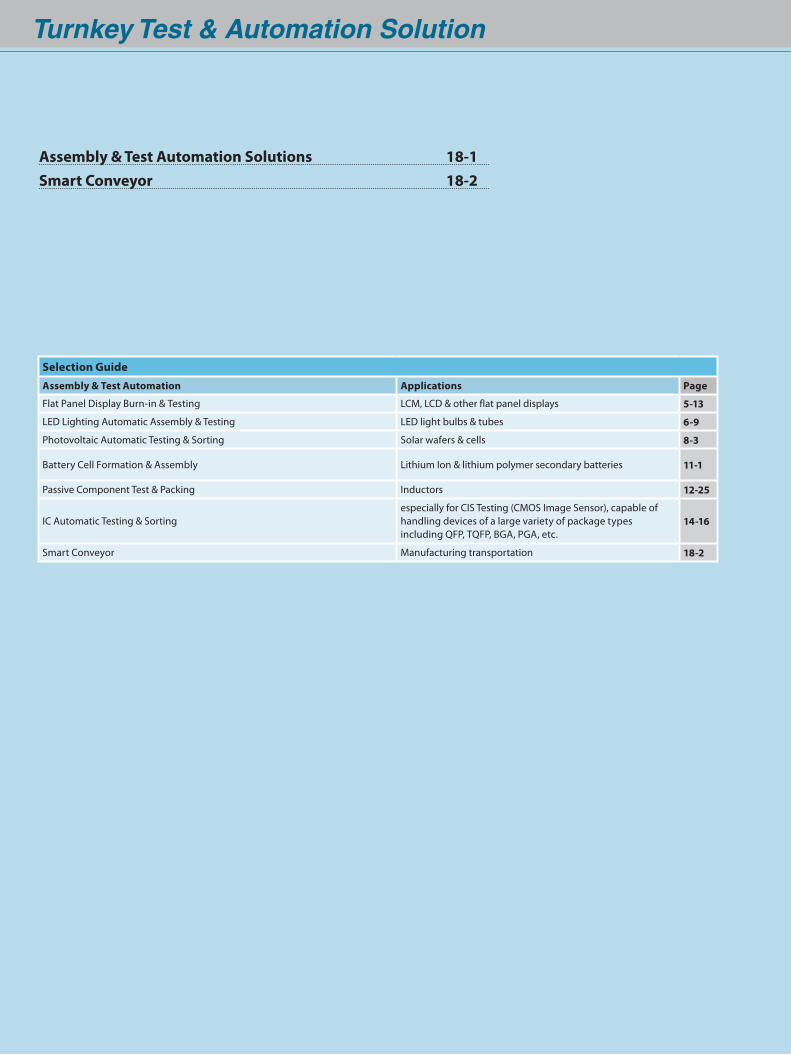
Turnkey Test & Automation Solution
Selection GuideAssembly & Test Automation Applications Page
Flat Panel Display Burn-in & Testing LCM, LCD & other flat panel displays 5-13
LED Lighting Automatic Assembly & Testing LED light bulbs & tubes 6-9
Photovoltaic Automatic Testing & Sorting Solar wafers & cells 8-3
Battery Cell Formation & Assembly Lithium Ion & lithium polymer secondary batteries 11-1
Passive Component Test & Packing Inductors 12-25
IC Automatic Testing & Sortingespecially for CIS Testing (CMOS Image Sensor), capable of handling devices of a large variety of package typesincluding QFP, TQFP, BGA, PGA, etc.
14-16
Smart Conveyor Manufacturing transportation 18-2
Assembly & Test Automation Solutions 18-1Smart Conveyor 18-2
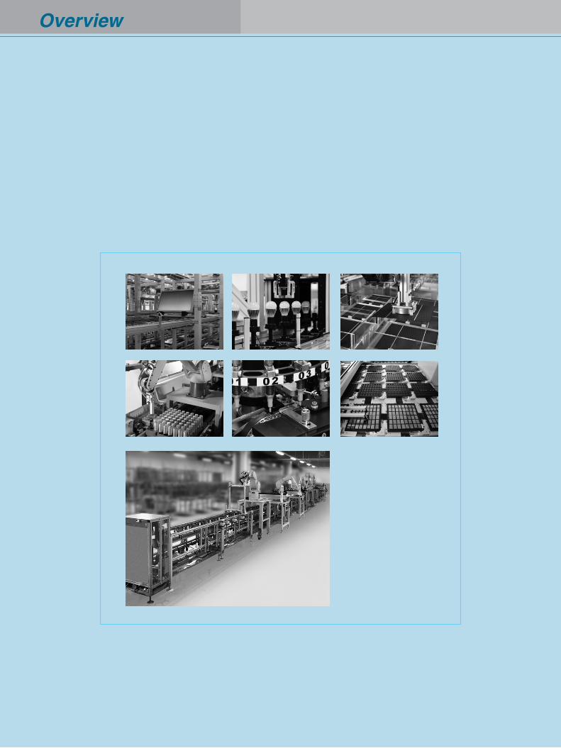
Overview
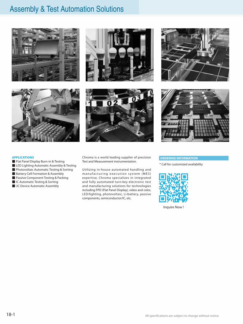
18-1 All specifications are subject to change without notice. All specifications are subject to change without notice.
Assembly & Test Automation Solutions
APPLICATIONS Flat Panel Display Burn-in & Testing LED Lighting Automatic Assembly & Testing Photovoltaic Automatic Testing & Sorting Battery Cell Formation & Assembly Passive Component Testing & Packing IC Automatic Testing & Sorting 3C Device Automatic Assembly
Chroma is a world leading supplier of precision Test and Measurement instrumentation.
Utilizing in-house automated handling and m a n u f a c t u r i n g e x e c u t i o n s y s t e m (M E S) expertise, Chroma specializes in integrated and fully automated turn-key electronic test and manufacturing solutions for technologies including FPD (Flat Panel Display), video and color, LED/lighting, photovoltaic, Li-battery, passive components, semiconductor/IC, etc.
* Call for customized availability
ORDERING INFORMATION
Inquire Now !
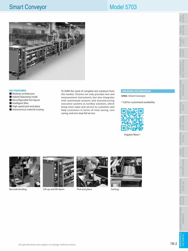
18-2All specifications are subject to change without notice. All specifications are subject to change without notice.
Flat PanelD
isplayPow
er Electronics
Electrical Safety
General
PurposePassive
Component
Semiconductor/
ICBattery Test & Autom
ationAutom
atedO
ptical Inspection Photovoltaic Test
& Automation
PXI Test &
Measurem
ent Intelligent
Manufacturing System
Video & Color
Turnkey Test & Autom
ation LED
/Lighting
Optical
Devices
Smart Conveyor
KEY FEATURES Modular architecture Hybrid Operating mode Reconfigurable line layout Intelligent lifter High speed pick and place Autonomous material routing
5703 : Smart Conveyor
* Call for customized availability
To fulfill the need of complete test solutions from the market, Chroma not only provides test and measurement instruments, but also integrates with automated systems and manufacturing execution systems as turnkey solutions, which bring more value and service to customers and help customers in terms of time saving, cost saving, and one-stop full service.
ORDERING INFORMATION
Barcode binding Lift up and lift down Sorting
Model 5703
Inquire Now !
Pick and place

For detail customer support services, please visit our website at www.chromaate.com For detail customer support services, please visit our website at www.chromaate.com
WARRANTY SERVICEC H R O M A AT E I N C . w a r r a n t s i t s i n s t r u m e nt s a g a i n s t a l l d e fe c t s i n work manship and mater ia l. I f you should experience a problem with your instrument, our technicians are available to help you over the phone, or find the nearest service support for timely repair.
CALIBRATION AND REPAIR SERVICEWhatever your test and measurement hardware support needs, Chroma can provide a reliable, cost-effective support selection that you can trust to reduce downtime and get you back to Business swiftly.
• Instrument CalibrationKeep your equipment operating with maximum precision: Chroma's calibration services are all traceable to national and international standards.
- On-site Calibration for All Major Instrument Brands - Service Center Instrument Calibration
• Instrument RepairChroma offers a var iet y of f lexible choices to maximize instrument uptime, with just the coverage you need for repair.
- Instrument Repair Agreements - Instrument Standard Repair
• Test System Calibration and RepairMaximize test system uptime. Chroma has flexible, custom-configurable service and support package, available on select solutions for your specific needs.- On-site System Calibration - On-site System Repair
Chroma offers total solutions in selling
the highest quality instrumentation
available and service. That begins
with the first call to Chroma and
cont inues af ter the sale through
long-term product support. Our sales
and service personnel work closely to
help you make the best selections for
your applications. Then we help you
maximize your investment by ensuring
optimum equipment performance.
All this is accomplished through
customer support programs ranging
from training to product installations
and a variety of maintenance plans.
19-1
HALT & HASS System
Radiation Test
Conduction Test
ESD Test
Optical Laboratory
Programmable Temperature & Humidity Chamber
Customer Support & Service
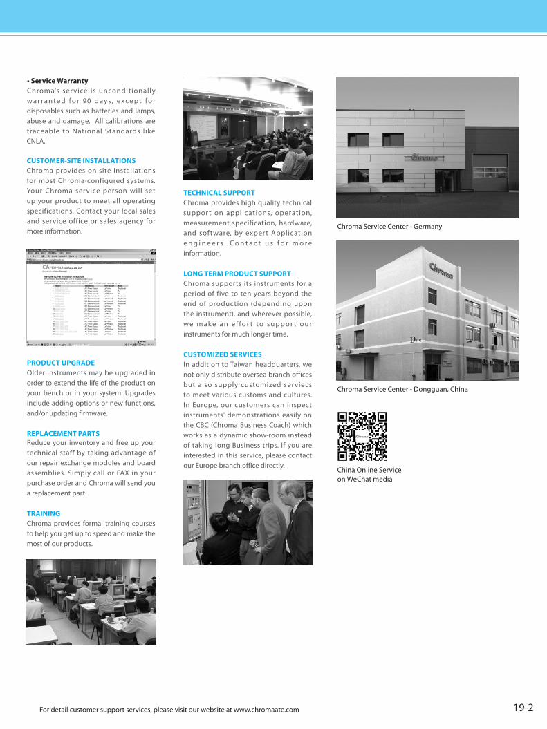
• Service WarrantyChroma's ser vice is unconditionally w a r r a n t e d fo r 90 d a y s, e xc e p t fo r disposables such as batteries and lamps, abuse and damage. All calibrations are traceable to National Standards like CNLA.
CUSTOMER-SITE INSTALLATIONSChroma provides on-site installations for most Chroma-configured systems. Your Chroma service person will set up your product to meet all operating specifications. Contact your local sales and service office or sales agency for more information.
PRODUCT UPGRADEOlder instruments may be upgraded in order to extend the life of the product on your bench or in your system. Upgrades include adding options or new functions, and/or updating firmware.
REPLACEMENT PARTSReduce your inventory and free up your technical staff by taking advantage of our repair exchange modules and board assemblies. Simply call or FAX in your purchase order and Chroma will send you a replacement part.
TRAININGChroma provides formal training courses to help you get up to speed and make the most of our products.
TECHNICAL SUPPORTChroma provides high quality technical support on applications, operation, measurement specification, hardware, and software, by expert Application e n g i n e e r s . C o n t a c t u s f o r m o r e information.
LONG TERM PRODUCT SUPPORTChroma supports its instruments for a period of five to ten years beyond the end of production (depending upon the instrument), and wherever possible, we m a k e a n e f fo r t to s u p p o r t o u r instruments for much longer time.
CUSTOMIZED SERVICESIn addition to Taiwan headquarters, we not only distribute oversea branch offices but also supply customized serviecs to meet various customs and cultures. In Europe, our customers can inspect instruments' demonstrations easily on the CBC (Chroma Business Coach) which works as a dynamic show-room instead of taking long Business trips. If you are interested in this service, please contact our Europe branch office directly.
For detail customer support services, please visit our website at www.chromaate.com For detail customer support services, please visit our website at www.chromaate.com 19-2
Chroma Service Center - Germany
Chroma Service Center - Dongguan, China
China Online Serviceon WeChat media

20-1
Global Service NetworkHEADQUARTERSChroma ATE Inc.66 Huaya 1st Road, Guishan, Taoyuan 33383, TaiwanTel: +886-3-327-9999Fax: +886-3-327-8898E-mail: [email protected]
HSINCHUChroma ATE Inc.Hsinchu Branch Office6F, No. 5, Technology Rd.,Science Park, Hsinchu City
30078, TaiwanTel: +886-3-563-5788Fax: +886-3-563-5758
KAOHSIUNGChroma ATE Inc.Kaohsiung Branch OfficeNo.1, Beineihuan E. Rd., Nanzi Dist., Kaohsiung City
81170, TaiwanTel:+886-7-365-6188Fax:+886-7-364-9500
OVERSEAS BRANCH OFFICESU.S.A.Chroma ATE, Inc. (U.S.A.)7 Chrysler, Irvine, CA 92618Tel: +1-949-421-0355Fax: +1-949-421-0353Toll Free: +1-800-478-2026E-mail: [email protected]
Chroma Systems Solutions, Inc.19772 Pauling, Foothill Ranch, CA 92610 Tel: +1-949-600-6400Fax: +1-949-600-6401E-mail: [email protected]
EUROPEChroma ATE Europe B.V. Morsestraat 32, 6716 AH Ede,The NetherlandsTel: +31-318-648282Fax: +31-318-648288E-mail: [email protected]
Chroma ATE GermanySüdtiroler Str. 9, 86165Augsburg, GermanyTel: +49-821-790967-0Fax: +49-821-790967-600E-mail: [email protected]
JAPAN 日本Chroma Japan Corp.888 Nippa-cho, Kouhoku-ku, Yokohama-shi, Kanagawa,
223-0057 JapanTel: +81-45-542-1118 Fax: +81-45-542-1080E-mail: [email protected]
SOUTHEAST ASIAQuantel Pte Ltd.(A Company of Chroma Group)46 Lorong 17 Geylang # 05-02 Enterprise Industrial Building, Singapore 388568 Tel: +65-6745-3200 Fax: +65-6745-9764 E-mail: [email protected]
HONG KONGNeworld Electronics Ltd.Unit 6, 6F, Shui Hing Centre, No. 13, Sheung Yuet Rd., Kowloon Bay,Kowloon, Hong KongTel: +852-2331-9350Fax: +852-2331-9406E-mail: [email protected]
CHINABEIJINGChroma Electronics (Shenzhen) Co., Ltd. Beijing Branch Office8F, Building 7, No.18 Feng ChuangTechnology Park, 13th Ke Chuang Street,Economic Technological Development Area, Yizhuang, Beijing, ChinaTel: +86-10-5764-9600, 5764-9601Fax: +86-10-5764-9609E-mail: [email protected]
SHANGHAIChroma Electronics (Shanghai) Co., Ltd.3F Building 40, No. 333, Qin Jiang Rd.,Shanghai, ChinaTel: +86-21-6495-9900Fax: +86-21-6495-3964E-mail: [email protected]
SUZHOUChroma ATE (Suzhou) Co., Ltd.Building 7, Shi Shan Industrial Gallery,No. 855, Zhu Jiang Rd., SuzhouNew District, Jiang Su, ChinaTel: +86-512-6824-5425Fax: +86-512-6824-0732E-mail: [email protected]
Chroma System Technology(Suzhou) Co., Ltd.503-1, 4th Floor Genway LOHASTOWN,
88 Building, 999 Xinghu Road,SIP Suzhou Tel: +86-512-6807-1889Fax: +86-512-6807-1886E-mail: [email protected]
CHONGQINGChroma Electronics (Shenzhen) Co., Ltd.Chongqing Branch OfficeBuilding 4 Longfor MOCO, No. 13-8,No.166, XinNan Rd, YuBei District,Chongqing, China Tel: +86-23-6703-4924 / 6764-4839Fax: +86-23-6311-5376E-mail: [email protected]
XIAMENChroma ATE (Suzhou) Co., Ltd.Xiamen Branch OfficeUnit 705-706, No.55 Building B,Wanghai Road, Software Park,Xiamen, Fujian, ChinaTel: +86-592-8262-055Fax: +86-592-5182-152E-mail: [email protected]
SHENZHENChroma Electronics (Shenzhen) Co., Ltd.8F, No.4, Nanyou Tian An Industrial Estate,Shenzhen, ChinaTel: +86-755-2664-4598Fax: +86-755-2641-9620E-mail: [email protected]
DONGGUAN Chroma Electronics (Shenzhen) Co., Ltd.Dongguan Branch Office3F,Building YD3-4, GuanchengTechnology Park,Shi Long Road,Guancheng District, Dongguan City,Guangdong, ChinaTel: +86-769-8663-9376Fax: +86-769-8631-0896E-mail: [email protected]
DISTRIBUTORSAUSTRALIAPower Parameters Pty Ltd.(Test & Measurement Instruments)
83 Northern Road, Heidelberg West 3081 Victoria, AustraliaTel: +61-3-9450-1500Fax: +61-3-9457-6327E-mail: [email protected]
AUSTRIADataTec GmbH(Test & Measurement Instruments)Ferdinand-Lassalle-Str. 52 D-72770 Reutlingen, GermanyTel: +49-7121 / 51 50 50E-mail: [email protected]
Universal Elektronik Import GmbH(Test & Measurement Instruments)Anton-Freunschlaggasse
49 AT-1230 Wien, AustriaTel: +43-1-5451-588 Fax: +43-1-5451-464 E-mail: [email protected]
BAHRAINDidactic Systems & Technology(Test & Measurement Instruments)M:03, Bldng No:P/09, Etihad, Muroor Road, Abu Dhab, P.O.Box NO: 73260Tel: +971-2-4918981 Fax: +971-2-4918982E-mail: [email protected]
BALKANS(Montenegro/Serbia/Croatia/Slovenia)ALL DATA EE d.o.o. (Test & Measurement Instruments)C. Zore Perello Godina 2 SI-6000 KoperTel: +386-5-9072606 Fax: +386-5-9072601 E-mail: [email protected]
BELARUSProfcon(Test & Measurement Instruments)Kropotkina Str. 91 A/ 4, Office 3A,
220002 Minsk, BelarusTel: +375-17 237 4211Fax: +375-17 283 1799E-mail: [email protected]
20-2
The areas and distributors are listed in alphabetical order.
BENELUXC.N. Rood N.V./S.A.(Test & Measurement/PXI Instruments, Semiconductor ATE)Z.1. Researchpark 40, B-1731 Zellik, BelgiumTel: +32-2-467-03-50 Email: [email protected]
TT&MS BV.(Test & Measurement Instruments)Frankweg 25, 2153 PDNieuw - Vennep, The NetherlandsTel: +31-252-621080Fax: +31-252-620702E-mail: [email protected]
BRAZILT&M Instruments Repres. Ltda (Test & Measurement Instruments)Rua Princesa Isabel,
1750-Brooklin-CEP, 04601-003, Sao Paulo-SP-BrazilTel: +55-11-5092-5229Fax: +55-11-5044-2414 E-mail: [email protected]
BULGARIAGIGA ELECTRONICS EOOD(Test & Measurement Instruments)
17, Manastirska Street 1111 Sofia, BulgariaTel: +359 2971 4919Fax: +359 2971 4919 E-mail: [email protected]
CZECH REPUBLICH TEST a.s.(Test & Measurement Instruments)Šafránkova 3, 15500 Praha 5.Czech republicTel: +420-2-3536-5207E-mail: [email protected]
Meatest s.r.o (Test & Measurement Instruments)Ksirova 118A, CZ-619 00 Brno,Czech Republic Tel: +420-5-4325-0886 Fax: +420-5-4325-0890 E-mail: [email protected]
DENMARKAtimco AS(Test & Measurement Instruments)BØgekildevej 7B DK-8361Hasselager, DenmarkTel: +45-86-258899Fax: +45-86-255889E-mail: [email protected]
Nortelco Electronics Danmark (Test & Measurement Instruments)Værkstedsgården 14, 1 DK-2620 Albertslund, Denmark Tel: +45-48 17 75 00 Fax: +45-48 17 75 10 E-mail: [email protected] www.nortelcoelectronics.dk
EGYPTTechnical Solution Engineering Co. (Test & Measurement Instruments)
57 Hosny Ahmed Khalaf St., Aprt. 3, Nasr City, EgyptTel: +202-670-6599Fax: +202-670-6183E-mail: [email protected]
FINLANDYE International(Test & Measurement Instruments)Luomannotko 6, FIN 02200 Espoo, FinlandTel: +35 810 289 1200Fax: +35 810 289 1270E-mail: [email protected]
FRANCEACQUISYS(PXI Instruments)
30 av Robert Surcouf 78960 Voisins le Bretonneux, FranceTel: +33-1-3452-4090 Email: [email protected]
MB Electronique(Test & Measurement Instruments)
106, rue des frères Farman ZI - BP 31F-78533 Buc Cedex, France Tel: +33-139-676-767Fax:+33-139-565-344E-mail: [email protected]
QUALITYSOURCE Groupe Spherea(Test & Measurement Instruments)Parc de I'Envol-2 rue du Marechal delattre de Tassigny-78990 elancourt, FranceTel: +33-130-489-966Fax: +33-130-432-846E-mail: [email protected]
GERMANYCompuMess Elektronik GmbH(Test & Measurement Instruments)Lise-Meitner-Strasse 4 D-85716 Unterschleißheim, GermanyTel: +49-89 321 50 10Fax: +49-89 321 50 11E-mail: [email protected]
DataTec GmbH(Test & Measurement Instruments)Ferdinand-Lassalle-Str. 52 D-72770 Reutlingen, GermanyTel: +49-7121 / 51 50 50E-mail: [email protected]
StanTronic Instruments GmbH(PXI Instruments)Keuper Weg 6, D-71083Herrenberg, GermanyTel: +49-7031-4100-8914 Fax: +49-7031-4100-8918 www.stantronic.deE-Mail: [email protected]
Schubert Technologies(Semiconductor ATE & Handler)Saentisstrasse 43, D-81825 Munich, GermanyTel: +49 89-4513-9633Fax: +49 89-4513-9628E-mail: [email protected] www.schubert-technologies.eu
GREECENetScope Solutions S.A. (Test & Measurement Instruments)
4, Lachana St., New Filadelfia 143 42 Athens, GreeceTel: +30-210-272-4107Fax: +30-210-271-1999E-mail: [email protected]
Vector Technologies LTD(Test & Measurement Instruments)Diogenous 40 Str. 152 34 Chalandri, Athens, GreeceTel: +30-210-6858-008Fax: +30-210-6858-118E-mail: [email protected]
HUNGARYEltest Ltd.(Test & Measurement Instruments)H-1015 Budapest, Hattyu u. 16, HungaryTel: +36-1-202-1873Fax: +36-1-225-0031E-mail: [email protected]
H TEST Hungary Kft.(Test & Measurement Instruments)Gyori Nemzetkozi Ipari Park,Gesztenyefa u. 4, H-9027 Gyor,HungaryTel: +36-96 999 262E-mail: [email protected]
Kora BT.(Test & Measurement Instruments)Torokor st. 31 H-1145 Budapest, HungaryTel: +36-1-223-1045Fax: +36-1-221-2541E-mail: [email protected]
INDIAQuantel Technologies India Private Limited (New Delhi)(Test & Measurement Instruments)K-13 Ground Floor, Lajpat Nagar-ll,New Delhi-110024Tel: +91-11-4132-5052Fax: +91-22-4015-6221E-mail: [email protected]
Quantel Technologies India Private Limited (Mumbai)(Test & Measurement Instruments)Unit No. 3134/3135, D Wing, 3rd Floor,Oberoi Garden Estate, Off Chandivali Farms Rd., Chandivali, Andheri(East), Mumbai-400072Tel: +91-22-4229-1008/4229-1002Fax: +91-22-4015-6221E-mail: [email protected]

20-3
Global Service NetworkQuantel Technologies India Private Limited (Bangalore)(Test & Measurement Instruments)No. 301, #130 Prestige Infantry Court Infantry Rd., Bangalore-560001Tel: +91-80-4094-1520/1507Fax: +91-80-4093-6673E-mail: [email protected]
MEL Systems & Services Ltd.(Head Office)(Test & Measurement Instruments)Plot # 173, Developed Plots Estate for Electrical, Electronic & Instrument Industries, Perungudi, Chennai - 600 096, IndiaTel: +91-44-2496-1903/04 Fax: +91-44-2496-0488 E-mail: [email protected]
MELSS Branch Office (Bangalore) (Test & Measurement Instruments)
203, 2nd Floor, 'MOTA CHAMBERS', No.9, Millers Road, Bangalore - 560 052 Tel : +91-8-2226-6546Fax : +91-8-2226-8205 E-mail: [email protected], [email protected]
MELSS Branch Office (Mumbai) (Test & Measurement Instruments)C/216A, Kailash Industrial Complex, Behind Godrej Residential Colony,Park Site,Vikhroli (West), Mumbai - 400079 Tel: +91-22-2518-0915/16 Telefax: +91-22-2518-0915 E-mail: [email protected], [email protected]
MELSS Branch Office (New Delhi) (Test & Measurement Instruments)C-52. 1st Floor, Shashi Garden(Opp, Dena Bank) Mayur Vihar Phase-I, Delhi-110091 Tel: +91-11-2275-8261 Telefax: +91-11-2275-8254/61 E-mail: [email protected],[email protected]
INDONESIAPT Quantel(Test & Measurement Instruments)Ruko Easton Blok D No. 10, Lippo Cikarang, Kelurahan Cibatu, Kecamatan Cikarang Selatan, Kabupaten Bekasi, IndonesiaTel: +62 813 2529 7885 [email protected]
IRANArvin Afzar Co.(Test & Measurement Instruments)No. 22 Sarmad St., North Sohrevardi Ave., Tehran 15539 IranTel: +98-21-8852-9254~5Fax: +98-21-8874-5984E-mail: [email protected]
Didactic Systems & Technology (Test & Measurement Instruments)M:03, Bldng No:P/09, Etihad, Muroor Road, Abu Dhab, P.O.Box NO: 73260Tel: +971-2-4918981 Fax: +971-2-4918982E-mail: [email protected]
IRAQDidactic Systems & Technology (Test & Measurement Instruments)M:03, Bldng No:P/09, Etihad, Muroor Road, Abu Dhab, P.O.Box NO: 73260Tel: +971-2-4918981 Fax: +971-2-4918982E-mail: [email protected]
IRELANDMDL Technologies Ltd.(Test & Measurement Instruments)Unit 11 Devonshire Business CentreWorks Road Letchworth Herts SG61GJ,United KingdomTel: +44-146-243-1981Fax: +44-560-315-2515E-mail: [email protected]
ISRAELMeltronics(Test & Measurement Instruments)
132 Menachem Begin Road St.
1 Azrieli Center Round Tower,
34th Floor Tel Aviv, IsraelTel: +972-03-644-4492 Fax: +972-77-345-0470 E-mail: [email protected]
ITALYAll Data S.r.l.(Test & Measurement Instruments)Via Volontari dle Sangue 1120092 Cinisello Balsamo (MI), ItalyTel: +39-0266 0155 66Fax: +39-0266 0155 77E-mail: [email protected]
Barletta Apparecchi Scientifici(Test & Measurement Instruments)VIA Prestinari 2-20158 Milano,ItalyTel: +39-02-3931-2000Fax: +39-02-3931-1616E-mail: [email protected]
JAPANCombex Co.,Ltd(Test & Measurement Instruments)
5-12,Kiyohara-cho,Ohta-shi,
373-8567 GunmaTel: +81-276-37-8521Fax: +81-276-37-8507www.combex.co.jp
Hodaka Denshi Co.,Ltd.(Test & Measurement Instruments)
834-2, Bukko-cho,Hodogaya-ku,Yokohama 240-0044Tel: +81-45-331-9302Fax: +81-45-333-9257www.hodaka.co.jp
KOKKA ELECTRIC CO., LTD.(Test & Measurement Instruments)
6-14,Tenman 1-chome, Kitaku,Osaka, 530-0043JapanTel: +81-6-6353-5551Fax: +81-6-6354-0173www.kokka-e.co.jp
Kyoritsu Electric Corporation(Test & Measurement Instruments)
61-1, Nakadahoncho,Suruga-ku, Shizuoka-shi, 422-8686 JapanTel: +81-54-288-8888Fax: +81-54-285-1105www.kdwan.co.jp
MAC SYSTEMS CORPORATION(Test & Measurement Instruments)Kusumoto 15 Building 6F,1-7-2, Nishiki, Naka-ku, Nagoya-shi, 460-0003, JapanTel: +81-52-223-2811Fax: +81-52-223-2810www.macsystems.co,jp
MEIJI ELECTRIC INDUSTRIES CO, LTD.(Test & Measurement Instruments)
13-8,Kameshima2-chome, Nakamura-ku, Nagoya,
453-8580 JapanTel: +81-52-451-7661Fax: +81-52-451-7659www.meijidenki.co.jp
Miwa Electric Industrial Corporation(Test & Measurement Instruments)Shinjuku Seven Bldg, 8-1, Shinjyuku
2-chome, Shinjyuku-ku, 160-0022,TokyoTel: +81-3-3341-2101Fax: +81-3-3341-4426www.miwadenki.co.jp
Nihon Denkei Co., Ltd. (Test & Measurement Instruments)Seikoukai kanda Building 5-12,
3-chome, sotokanda, chiyoda-ku, Tokyo, 101-0021 JapanTel: +81-3-3251-5731Fax: +81-3-3251-5730www.n-denkei.co.jp
SANYU ELECTRONIC INDUSTRIAL CO., LTD(Test & Measurement Instruments)
2F,ALPS LOGISTIC #1 BUILD 1756NIPPA-CHO,KOHOKU-KU, YOKOHAMA, KANAGAWA 223-0057 JapanTel: +81-45-545-7771Fax: +81-45-545-7778www.sanyu-ele.co.jp
TOKYO DENKI SANGYO CO., LTD.(Test & Measurement Instruments)
1-18-12, Hatagaya, Shibuya-ku,Tokyo,151-0072 JapanTel: +81-3-3481-1111Fax: +81-3-3481-1125www.tokyo-densan.co.jp
TOYO Corporation(Power Testing Equipment)
1-6, Yaesu 1-chome, Chuo-ku, Tokyo, 103-8284, JapanTel: +81-3-3279-0771Fax: +81-3-3246-0645E-mail: [email protected]

20-4
The areas and distributors are listed in alphabetical order.
KOREABRIDGE Corporation(Semiconductor ATE)
901 ho, Byucksan Technopia, 434-6, Sangdaewon-dong,Jungwon-gu, Sungnam-si, Kyoungki-do, KoreaTel: +82-31-747-4011 Fax: +82-31-747-4022E-mail: [email protected]
JEILMI Co., Ltd.(Test & Measurement Instruments)
9th FL, 401, Simin-daero,Dongan-gu, Anyang-si, Gyeonggi-do, Korea, Zip:14057Tel: +82-31-463-3700Fax: +82-31-463-3701E-mail: [email protected], [email protected]
LEEBESTECH(Test & Measurement Instruments)Room #520, Shinhan Deview Officetel
1132-19, Guwol-dong, Namdong-gu, Incheon, South Korea #405-220Tel: +82-32-437-0367Fax: +82-32-437-0368E-mail: [email protected]@hanafos.com
NOISE Technology Co., Ltd.(AC Source, Load, Power Analyzer)Science Bldg, 3, Pangyo-ro 715 beon-gil, Bundang-gu, Seongnam-si, Gyeonggi-do, KoreaTel: +82-31-781-7816Fax: +82-31-703-7175E-mail: [email protected]
TF EastPost Technologies Inc.(Semiconductor Handler)Science Bldg, #149-9, Yatap-dong, Bundang-gu, Seongnam-si, Kyunggi-do,
463-816, KoreaTel: +82-31-206-0541Fax: +82-31-206-0543E-mail: [email protected]
WE Corporation(Test & Measurement Instruments)
2F, 85 Nambusunhwanno315gil, Seocho-gu, Seoul, KoreaTel: +82-2-585-8253Fax: +82-2-585-8254E-mail: [email protected]
KUWAITDidactic Systems & Technology (Test & Measurement Instruments)M:03, Bldng No:P/09, Etihad, Muroor Road, Abu Dhab, P.O.Box NO: 73260Tel: +971-2-4918981 Fax: +971-2-4918982E-mail: [email protected]
MALAYSIAQuantel Global Sdn Bhd. (Kuala Lumpur)(Test & Measurement Instruments)Unit 802, 8F, Blk A Damansara Intan, No. 1, Jalan SS20/27, 47400 Petaling Jaya, Selangor, MalaysiaTel: +60-3-7726-7435Fax: +60-3-7726-1961E-mail: [email protected]
Quantel Global Sdn Bhd. (Penang)(Test & Measurement Instruments)
2-3-9 One Square, Tingkat Mahsuri 1Bayan Lepas, 11950 Penang MalaysiaTel: +60-4-646-5110/0780Fax: +60-4-644-2878E-mail: [email protected]
QTEC Technologies Sdn Bhd.(Head Office)(PV/LED/Semiconductor ATE & Handler)
3637, Jalan Angkasa Nuri 1, Taman Angkasa Nuri, 76100 Durian Tunggal, Melaka, MalaysiaTel: +60-6-334-2918/2919Fax: +60-6-334-2920E-mail: [email protected] [email protected]
NEW ZEALANDElectrotest Ltd.(Test & Measurement Instruments)PO Box 300 475 , 12A Te Kea PlaceAlbany, Auckland, New ZealandTel: +64-9-448-2600Fax: +64-9-448-2611E-mail: [email protected]
NORWAYIKM Instrutek AS(Test & Measurement Instruments)Elveveien 28, N-3262 Larvik, NorwayTel: +47-33-165700Fax: +47-33-165701E-mail: [email protected]
Nortelco Electronics AS(Test & Measurement Instruments)Johan Scharffenbergs vei 95,
0694 Oslo, Norway Tel: +47 2257 6100 Fax: +47 2257 6130 E-mail: [email protected] www.nortelcoelectronics.no
OMANDidactic Systems & Technology (Test & Measurement Instruments)Wadi Al Udhaiba St., Azaiba- Muscat., Sultanate of OmanTel: +968-24615120 Fax: +968-24615117 E-mail: [email protected]
PHILIPPINESQuantel Global Philippines Corporation (Manila & Cebu)(Test & Measurement Instruments)Units 2401 and 2402 The Orient Square, F. Ortigas Jr. Road, Ortigas Center, Psig City, PhilippinesTel: +63-2638-6942/6918 (Manila)Fax: +63-2638-6946 (Manila)Tel: +63-32-495-9210 (Cebu)Fax: +63-32-511-0071 (Cebu)E-mail: [email protected]
POLANDNDN Test & Measurement instruments(Test & Measurement Instruments)Janowskiego Str. 15 PL 02-784Warsaw, PolandTel: +48-22-641-1547Fax: +48-22-644-4250E-mail: [email protected]
PORTUGALInstrumentos de Medida, S.L.(Test & Measurement Instruments)Septiembre 31, E28022 MadridTel: +34-91-300-0191Fax: +34-91-388-5433E-mail: [email protected]
Lenave Lda(Test & Measurement Instruments)R. de S. Paulo 228-2321200-430 Lisboa, PortugalTel: +351-213-223-190Fax: +351-213-420-968E-mail: [email protected]
QATARDidactic Systems & Technology(Test & Measurement Instruments)M:03, Bldng No:P/09, Etihad, Muroor Road, Abu Dhab, P.O.Box NO: 73260Tel: +971-2-4918981 Fax: +971-2-4918982E-mail: [email protected]
ROMANIAEE TEST S.A.(Test & Measurement Instruments)Blvd. Industriilor no. 4 ROM-300 714 Timisoara, RomaniaTel: +40-256-491-154Fax: +40-256-493-468E-mail:[email protected]
TECHNO VOLT s.r.l.(Test & Measurement Instruments)Bd. Constructorilor 20A, sector 6,
060512 Bucharest, Romania Tel: +40-21-220-1302Fax: +40-21-221-0925 E-mail: [email protected] www.test-expert.ru/en
RUSSIATESTPRIBOR, JSC(Test & Measurement Instruments)Office 718 24 Geroev Panfilovtsev Street, Moscow 125480, Russian Federation Tel: +7-495-225-67-37 Fax: +7-495-496-95-55 E-mail: [email protected] www.test-expert.ru/en

20-5
Global Service NetworkYE International(Test & Measurement Instruments)Pr. Obukhovskoy Oborony, Block 70, Building 3A, 192029, Saint-Petersburg, Russia Tel: +78-123 133 440 Fax: +78-123 133 441 E-mail: [email protected] www.yeint.ru
SAUDI ARABIADidactic Systems & Technology(Test & Measurement Instruments)M:03, Bldng No:P/09, Etihad, Muroor Road, Abu Dhab, P.O.Box NO: 73260Tel: +971-2-4918981 Fax: +971-2-4918982E-mail: [email protected]
SINGAPOREQuantel Pte Ltd. (Head Office)(Test & Measurement Instruments,PV/LED/Semiconductor ATE & Handler)
46 Lorong 17 Geylang # 05-02 Enterprise Industrial Building, Singapore 388568 Tel: +65-6745-3200 Fax: +65-6745-9764 E-mail: [email protected]
SLOVAKIAH TEST Slovakia spol. s r.o.(Test & Measurement Instruments)Zvolenská cesta 20, 97405 Banska Bystrica, SlovenskoTel: +421-905-785550E-mail: [email protected]
SOUTH AFRICAIntercal cc(Test & Measurement Instruments)Labotec Park 21 Bavaria RoadRandjespark Midrand,South AfricaTel: +27-11-315-4321 Fax: +27-11-312-1322 E-mail: [email protected]
SPAINEnelec S.L.(Test & Measurement Instruments)Avda. Francesc Macià, 39, 6˚ 2a
08206 Sabadell (Barcelona), SpainTel: +34-93-723-0270Fax: +34-93-723-4717E-mail: [email protected]
Instrumentos de Medida, S.L.(Test & Measurement Instruments)Septiembre 31, E28022 Madrid, SpainTel: +34-91-300-0191Fax: +34-91-388-5433E-mail: [email protected]
SWEDENCombinova AB(Test & Measurement Instruments)Domkraftsv. 1, SE-197 40 Bro, SwedenTel: +46-8-627-9310Fax: +46-8-295-985E-mail: [email protected]
Nortelco Electronics(Test & Measurement Instruments)Sverige, Kanalvägen 1A, SE-194 61, Upplands Väsby, Sweden Tel: +46 8 446 0100 Fax: +47 2257 6130 E-mail: [email protected] www.nortelcoelectronics.se
SWITZERLANDMESATEC technische Produkte AG (Test & Measurement Instruments)Sumpfstrasse 3, CH-6300 Zug, SwitzerlandTel: +41-41-740-5833Fax: +41-41-740-5834E-mail: [email protected]
THAILANDQuantel Global Co., Ltd(Test & Measurement Instruments)
2170 Bangkok Tower, 5th Floor, Room No. 502, New Petchaburi Road, Bangkapi, Huay Kwang Bangkok,
10310, ThailandTel: +66-2-308-0881-3Fax:+66-2-308-0884 E-mail: [email protected]
TUNESIAResonance Automation(Test & Measurement Instruments)
08 Rue El Aghlab, Borj El Ouzir, Ariana, TunisiaTel: +216-507-903-37E-mail: [email protected]
TURKEYYıldırım Elektronik Tic. Ve San. Ltd. Sti(Test & Measurement Instruments)Maresal Fevzi Cakmak Caddesi No:29
06500 Besevler Cankaya/ANKARATel: +90-312-221-1000Fax: +90-312-212-3535E-mail: [email protected] www.yildirimelektronik.com
UNITED ARAB EMIRATESDidactic Systems & Technology (Abudhabi)(Test & Measurement Instruments)M:03, Bldng No:P/09, Etihad, Muroor Road, Abu Dhab, P.O.Box NO: 73260Tel: +971-2-4918981 Fax: +971-2-4918982E-mail: [email protected]
Didactic Systems & Technology(Al Ain)(Test & Measurement Instruments)Hele, RumailaTel: +971-3-7662230 Fax: +971-3-7631047 E-mail: [email protected]
Didactic Systems & Technology(Dubai)(Test & Measurement Instruments)
114,Saleh Bin Lahej (Chilis Building), Al Garhoud, Dubai, P.O Box:233658Tel: +971-4-2525160 Fax: +971-4-2525161E-mail: [email protected]
UNITED KINGDOMMDL Technologies Ltd.(Test & Measurement Instruments)Unit 11 Devonshire Business Centre Works Road Letchworth Herts SG61GJ,United KingdomTel: +44-146-243-1981Fax: +44-560-315-2515E-mail: [email protected]
UKRAINESEA Electronics Ukraine LLC(Test & Measurement Instruments)Building 2, 13-B, Krakovskaya Str. 02094 Kyiv, UkraineTel: +38-44-291-00-41Fax: +38-44-291-00-41www.sea.com.ua
VIETNAMQuantel Global Vietnam Co. Ltd. (Hanoi)(Test & Measurement Instruments)Floor 6th, HL Tower, Lot A2B, Lane 82, Duy Tan Road, Dich Vong Hau Ward, Cau Giay district, Hanoi, VietnamTel: +84 4 3226 2510Fax: +84 4 3226 2511E-mail: [email protected]
Quantel Global Vietnam Co. Ltd. (HCM)(Test & Measurement Instruments)
4.14-4.15, The Prince Residence,
17-19-21 Nguyen Van Troi, Phu Nhuan, Ho Chi Minh, VietnamTel: +84-4-3226-2510Fax: +84-4-3226-2511E-mail: [email protected]
Global Service Network

20-6
The areas and distributors are listed in alphabetical order.
The areas and distributors are listed in alphabetical order.

w w w . c h r o m a a t e . c o m
TM
Distributed by:
Worldwide Distribution and Service Network201703-3570
CH
RO
MA
AT
E IN
C. Te
st & M
easu
rem
en
t Pro
du
ct Catalo
g 2
01
7
Test & Measurement2017 Product Catalog